Embed Size (px)
Citation preview
Victor BB Comprehensive Guide
Preliminary
Revision 1.4
Victor BB Comprehensive Guide
vexrobotics.com
Copyright 2016, VEX Robotics Inc. 2016-10-21 2
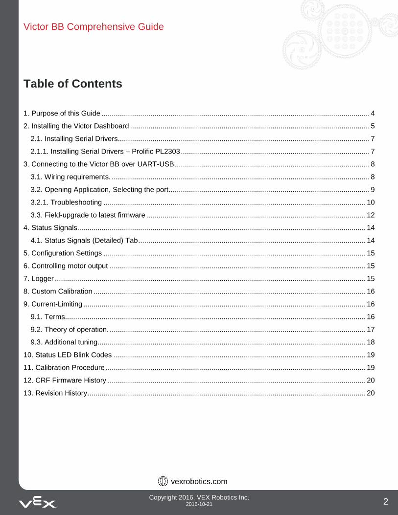
Table of Contents
1. Purpose of this Guide .................................................................................................................................... 4
2. Installing the Victor Dashboard ...................................................................................................................... 5
2.1. Installing Serial Drivers ............................................................................................................................ 7
2.1.1. Installing Serial Drivers – Prolific PL2303 ............................................................................................. 7
3. Connecting to the Victor BB over UART-USB ................................................................................................ 8
3.1. Wiring requirements. ............................................................................................................................... 8
3.2. Opening Application, Selecting the port ................................................................................................... 9
3.2.1. Troubleshooting ................................................................................................................................. 10
3.3. Field-upgrade to latest firmware ............................................................................................................ 12
4. Status Signals.............................................................................................................................................. 14
4.1. Status Signals (Detailed) Tab ................................................................................................................ 14
5. Configuration Settings ................................................................................................................................. 15
6. Controlling motor output .............................................................................................................................. 15
7. Logger ......................................................................................................................................................... 15
8. Custom Calibration ...................................................................................................................................... 16
9. Current-Limiting ........................................................................................................................................... 16
9.1. Terms .................................................................................................................................................... 16
9.2. Theory of operation. .............................................................................................................................. 17
9.3. Additional tuning.................................................................................................................................... 18
10. Status LED Blink Codes ............................................................................................................................ 19
11. Calibration Procedure ................................................................................................................................ 19
12. CRF Firmware History ............................................................................................................................... 20
13. Revision History ......................................................................................................................................... 20
Victor BB Comprehensive Guide
vexrobotics.com
Copyright 2016, VEX Robotics Inc. 2016-10-21 3
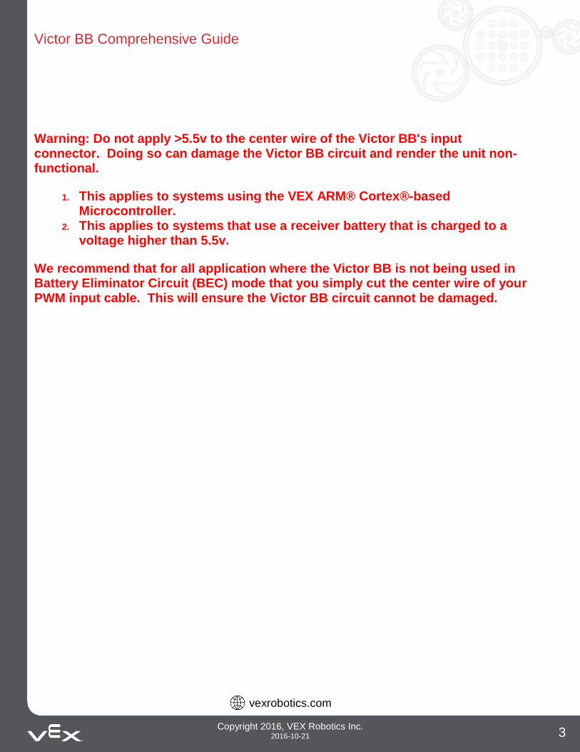
Warning: Do not apply >5.5v to the center wire of the Victor BB's input connector. Doing so can damage the Victor BB circuit and render the unit non-functional.
1. This applies to systems using the VEX ARM® Cortex®-based Microcontroller.
2. This applies to systems that use a receiver battery that is charged to a voltage higher than 5.5v.
We recommend that for all application where the Victor BB is not being used in Battery Eliminator Circuit (BEC) mode that you simply cut the center wire of your PWM input cable. This will ensure the Victor BB circuit cannot be damaged.
Victor BB Comprehensive Guide
vexrobotics.com
Copyright 2016, VEX Robotics Inc. 2016-10-21 4
1. Purpose of this Guide The purpose of this guide is to document the functionality of the Victor BB Motor Controller.
Victor BB Comprehensive Guide
vexrobotics.com
Copyright 2016, VEX Robotics Inc. 2016-10-21 5
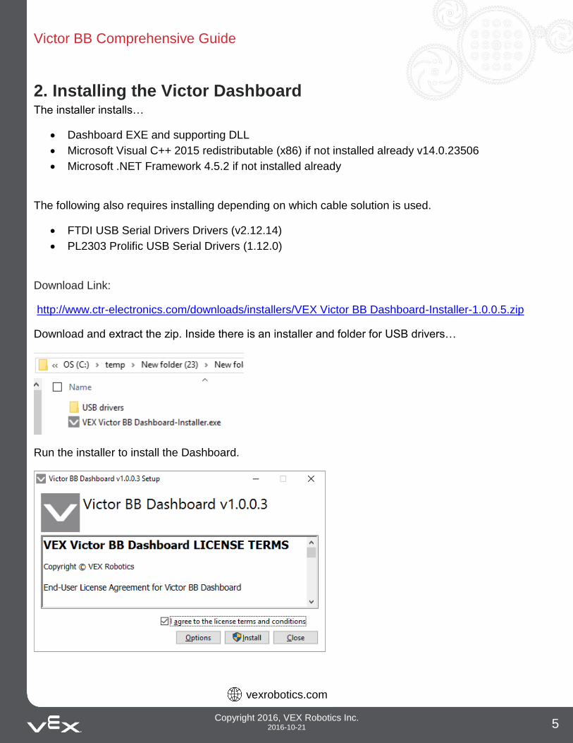
2. Installing the Victor Dashboard The installer installs…
Dashboard EXE and supporting DLL
Microsoft Visual C++ 2015 redistributable (x86) if not installed already v14.0.23506
Microsoft .NET Framework 4.5.2 if not installed already
The following also requires installing depending on which cable solution is used.
FTDI USB Serial Drivers Drivers (v2.12.14)
PL2303 Prolific USB Serial Drivers (1.12.0)
Download Link:
http://www.ctr-electronics.com/downloads/installers/VEX Victor BB Dashboard-Installer-1.0.0.5.zip
Download and extract the zip. Inside there is an installer and folder for USB drivers…
Run the installer to install the Dashboard.
Victor BB Comprehensive Guide
vexrobotics.com
Copyright 2016, VEX Robotics Inc. 2016-10-21 6
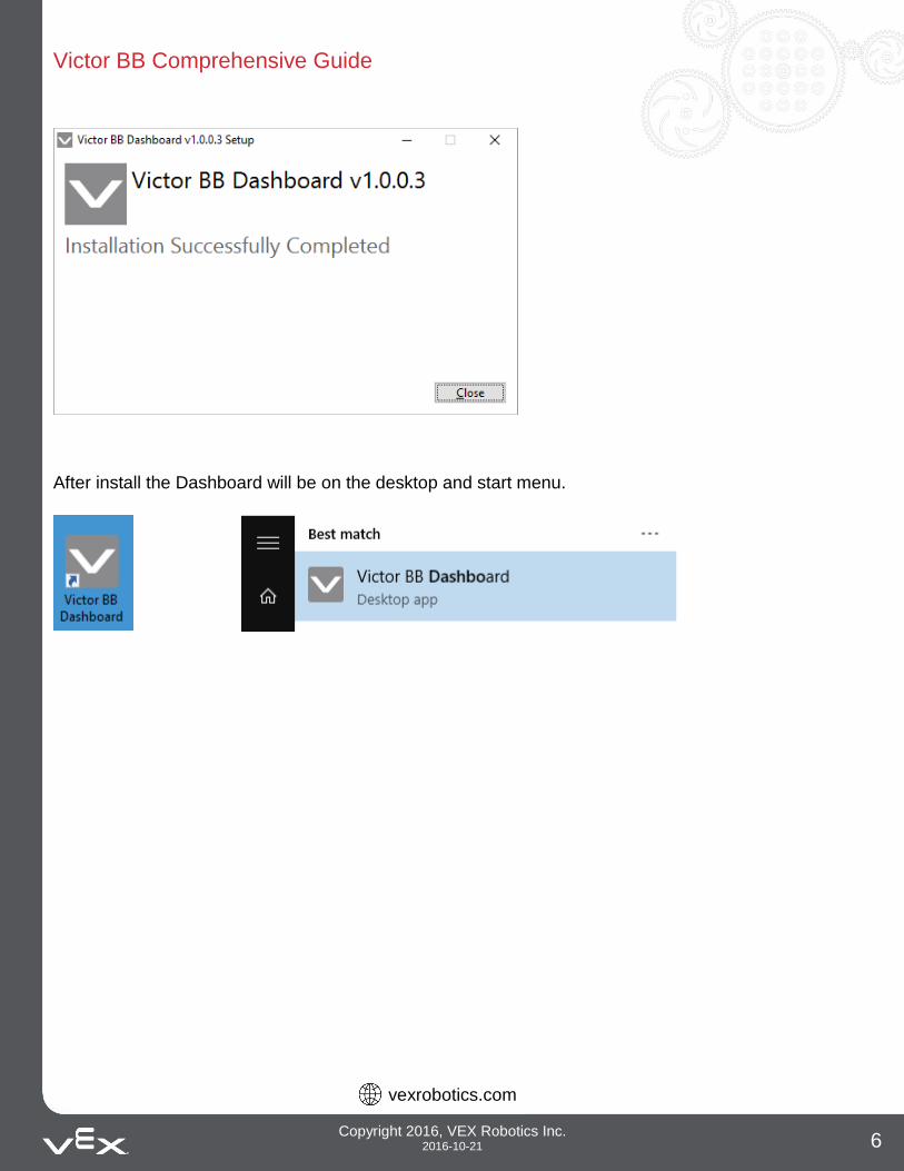
After install the Dashboard will be on the desktop and start menu.
Victor BB Comprehensive Guide
vexrobotics.com
Copyright 2016, VEX Robotics Inc. 2016-10-21 7
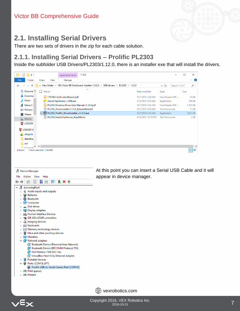
2.1. Installing Serial Drivers There are two sets of drivers in the zip for each cable solution.
2.1.1. Installing Serial Drivers – Prolific PL2303 Inside the subfolder USB Drivers/PL2303/1.12.0, there is an installer exe that will install the drivers.
At this point you can insert a Serial USB Cable and it will
appear in device manager.
Victor BB Comprehensive Guide
vexrobotics.com
Copyright 2016, VEX Robotics Inc. 2016-10-21 8
3. Connecting to the Victor BB over UART-USB
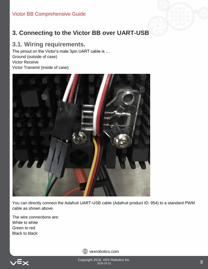
3.1. Wiring requirements. The pinout on the Victor’s male 3pin UART cable is …
Ground (outside of case)
Victor Receive
Victor Transmit (inside of case)
You can directly connect the Adafruit UART-USB cable (Adafruit product ID: 954) to a standard PWM
cable as shown above.
The wire connections are:
White to white
Green to red
Black to black
Victor BB Comprehensive Guide
vexrobotics.com
Copyright 2016, VEX Robotics Inc. 2016-10-21 9
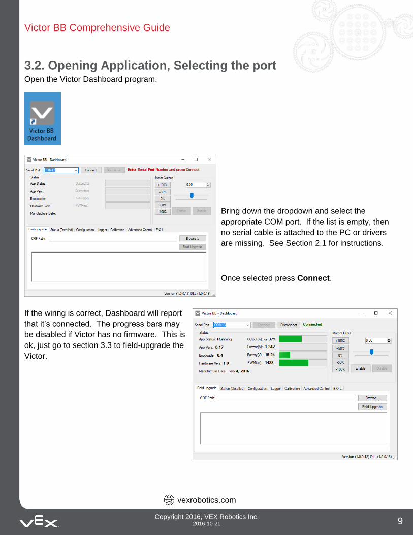
3.2. Opening Application, Selecting the port Open the Victor Dashboard program.
Bring down the dropdown and select the
appropriate COM port. If the list is empty, then
no serial cable is attached to the PC or drivers
are missing. See Section 2.1 for instructions.
Once selected press Connect.
If the wiring is correct, Dashboard will report
that it’s connected. The progress bars may
be disabled if Victor has no firmware. This is
ok, just go to section 3.3 to field-upgrade the
Victor.
Victor BB Comprehensive Guide
vexrobotics.com
Copyright 2016, VEX Robotics Inc. 2016-10-21 10
3.2.1. Troubleshooting
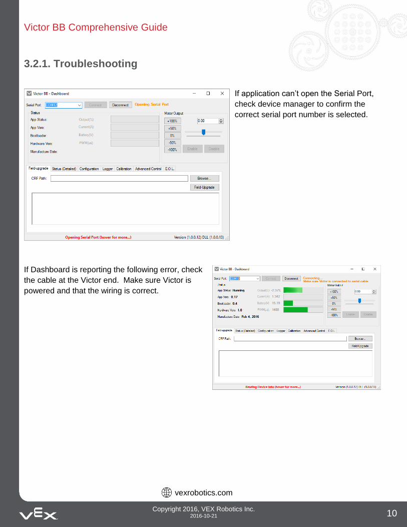
If application can’t open the Serial Port,
check device manager to confirm the
correct serial port number is selected.
If Dashboard is reporting the following error, check
the cable at the Victor end. Make sure Victor is
powered and that the wiring is correct.
Victor BB Comprehensive Guide
vexrobotics.com
Copyright 2016, VEX Robotics Inc. 2016-10-21 11
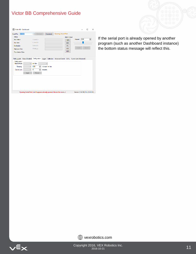
If the serial port is already opened by another
program (such as another Dashboard instance)
the bottom status message will reflect this.
Victor BB Comprehensive Guide
vexrobotics.com
Copyright 2016, VEX Robotics Inc. 2016-10-21 12
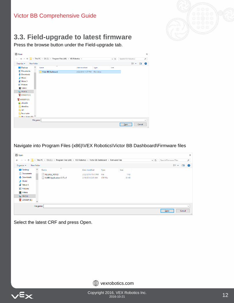
3.3. Field-upgrade to latest firmware Press the browse button under the Field-upgrade tab.
Navigate into Program Files (x86)\VEX Robotics\Victor BB Dashboard\Firmware files
Select the latest CRF and press Open.
Victor BB Comprehensive Guide
vexrobotics.com
Copyright 2016, VEX Robotics Inc. 2016-10-21 13
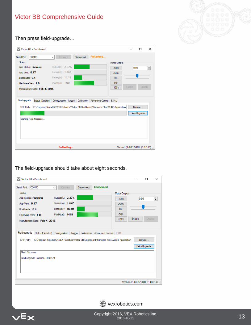
Then press field-upgrade…
The field-upgrade should take about eight seconds.
Victor BB Comprehensive Guide
vexrobotics.com
Copyright 2016, VEX Robotics Inc. 2016-10-21 14
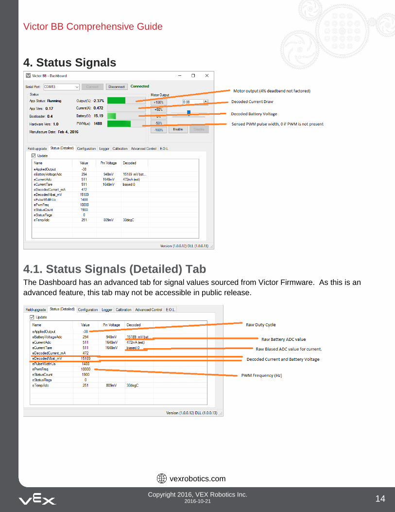
4. Status Signals
4.1. Status Signals (Detailed) Tab The Dashboard has an advanced tab for signal values sourced from Victor Firmware. As this is an
advanced feature, this tab may not be accessible in public release.
Victor BB Comprehensive Guide
vexrobotics.com
Copyright 2016, VEX Robotics Inc. 2016-10-21 15
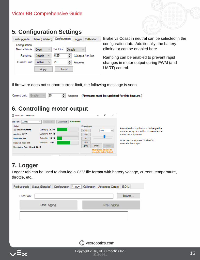
5. Configuration Settings Brake vs Coast in neutral can be selected in the
configuration tab. Additionally, the battery
eliminator can be enabled here.
Ramping can be enabled to prevent rapid
changes in motor output during PWM (and
UART) control.
If firmware does not support current-limit, the following message is seen.
6. Controlling motor output
7. Logger Logger tab can be used to data log a CSV file format with battery voltage, current, temperature,
throttle, etc...
Victor BB Comprehensive Guide
vexrobotics.com
Copyright 2016, VEX Robotics Inc. 2016-10-21 16
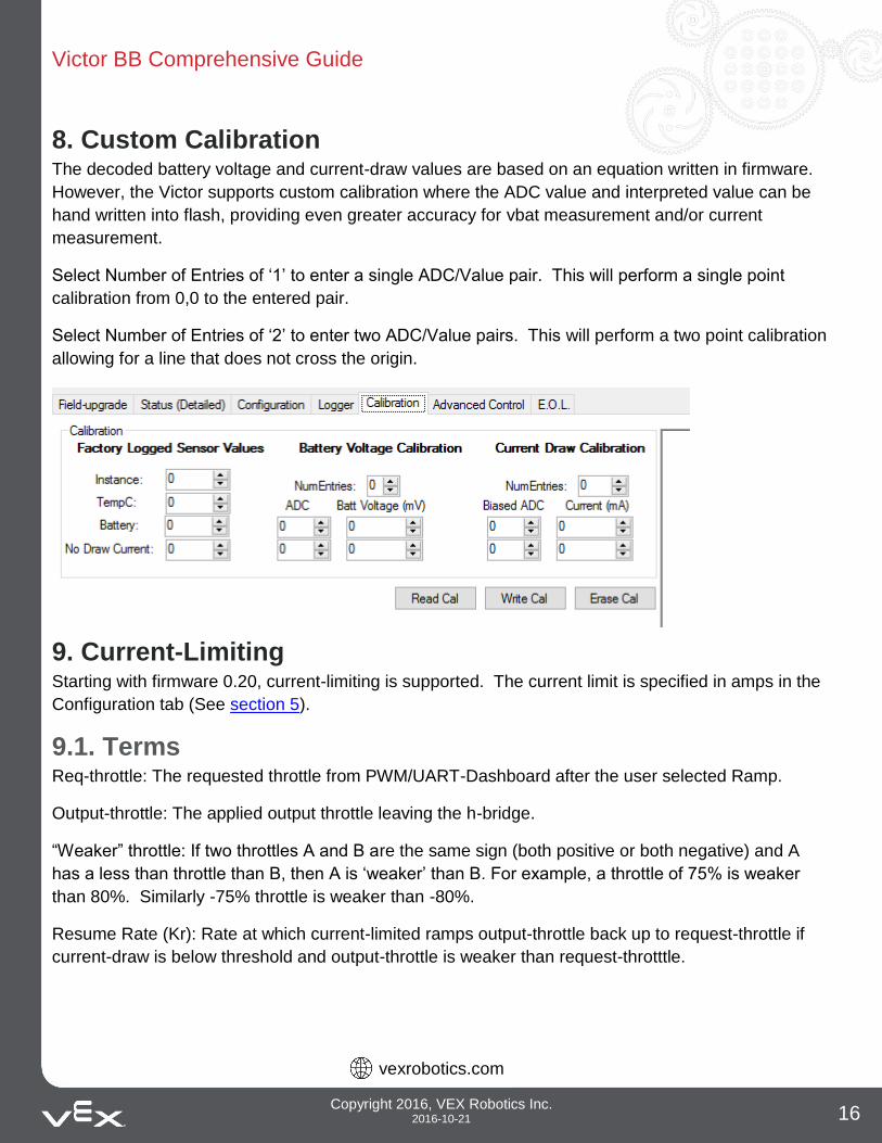
8. Custom Calibration The decoded battery voltage and current-draw values are based on an equation written in firmware.
However, the Victor supports custom calibration where the ADC value and interpreted value can be
hand written into flash, providing even greater accuracy for vbat measurement and/or current
measurement.
Select Number of Entries of ‘1’ to enter a single ADC/Value pair. This will perform a single point
calibration from 0,0 to the entered pair.
Select Number of Entries of ‘2’ to enter two ADC/Value pairs. This will perform a two point calibration
allowing for a line that does not cross the origin.
9. Current-Limiting Starting with firmware 0.20, current-limiting is supported. The current limit is specified in amps in the
Configuration tab (See section 5).
9.1. Terms Req-throttle: The requested throttle from PWM/UART-Dashboard after the user selected Ramp.
Output-throttle: The applied output throttle leaving the h-bridge.
“Weaker” throttle: If two throttles A and B are the same sign (both positive or both negative) and A
has a less than throttle than B, then A is ‘weaker’ than B. For example, a throttle of 75% is weaker
than 80%. Similarly -75% throttle is weaker than -80%.
Resume Rate (Kr): Rate at which current-limited ramps output-throttle back up to request-throttle if
current-draw is below threshold and output-throttle is weaker than request-throtttle.
Victor BB Comprehensive Guide
vexrobotics.com
Copyright 2016, VEX Robotics Inc. 2016-10-21 17
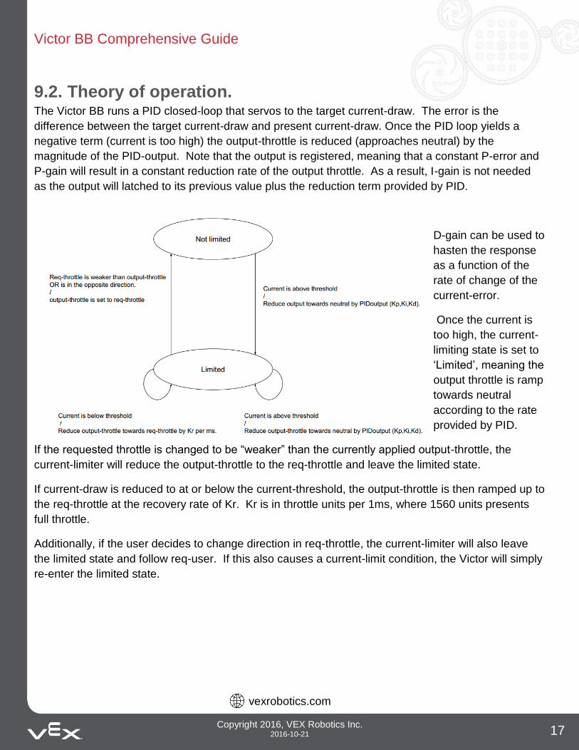
9.2. Theory of operation. The Victor BB runs a PID closed-loop that servos to the target current-draw. The error is the
difference between the target current-draw and present current-draw. Once the PID loop yields a
negative term (current is too high) the output-throttle is reduced (approaches neutral) by the
magnitude of the PID-output. Note that the output is registered, meaning that a constant P-error and
P-gain will result in a constant reduction rate of the output throttle. As a result, I-gain is not needed
as the output will latched to its previous value plus the reduction term provided by PID.
D-gain can be used to
hasten the response
as a function of the
rate of change of the
current-error.
Once the current is
too high, the current-
limiting state is set to
‘Limited’, meaning the
output throttle is ramp
towards neutral
according to the rate
provided by PID.
If the requested throttle is changed to be “weaker” than the currently applied output-throttle, the
current-limiter will reduce the output-throttle to the req-throttle and leave the limited state.
If current-draw is reduced to at or below the current-threshold, the output-throttle is then ramped up to
the req-throttle at the recovery rate of Kr. Kr is in throttle units per 1ms, where 1560 units presents
full throttle.
Additionally, if the user decides to change direction in req-throttle, the current-limiter will also leave
the limited state and follow req-user. If this also causes a current-limit condition, the Victor will simply
re-enter the limited state.
Victor BB Comprehensive Guide
vexrobotics.com
Copyright 2016, VEX Robotics Inc. 2016-10-21 18
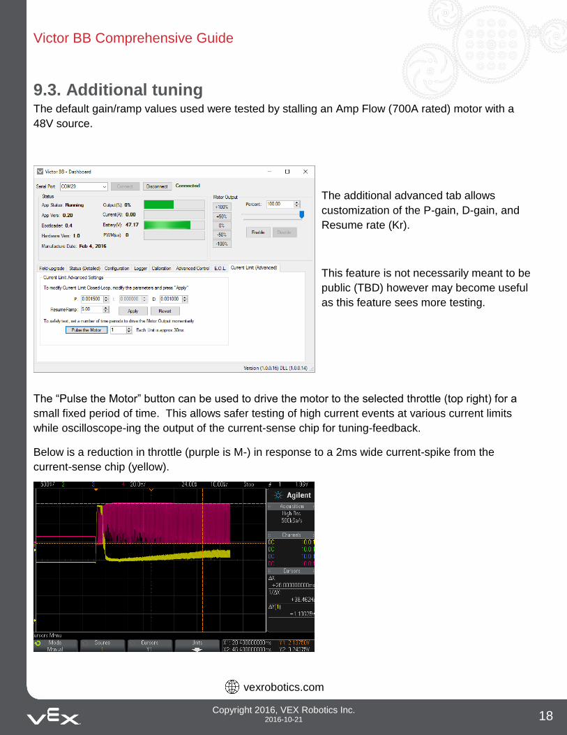
9.3. Additional tuning The default gain/ramp values used were tested by stalling an Amp Flow (700A rated) motor with a
48V source.
The additional advanced tab allows
customization of the P-gain, D-gain, and
Resume rate (Kr).
This feature is not necessarily meant to be
public (TBD) however may become useful
as this feature sees more testing.
The “Pulse the Motor” button can be used to drive the motor to the selected throttle (top right) for a
small fixed period of time. This allows safer testing of high current events at various current limits
while oscilloscope-ing the output of the current-sense chip for tuning-feedback.
Below is a reduction in throttle (purple is M-) in response to a 2ms wide current-spike from the
current-sense chip (yellow).
Victor BB Comprehensive Guide
vexrobotics.com
Copyright 2016, VEX Robotics Inc. 2016-10-21 19
10. Status LED Blink Codes
Blink Codes During Calibration
Status LED Blink Code Victor BB State Flashing Red/Green Calibration Mode
Blinking Green Successful Calibration
Blinking Red Failed Calibration
Blink Codes During Normal Operation
Status LED Blink Code Victor BB State Solid Orange PWM signal is within 4% of deadband
Blinking Red Reverse PWM is applied – Blink speed is proportional to input
Solid Red Full Reverse PWM is applied
Blinking Green Forward PWM is applied – Blink speed is proportional to input
Solid Green Full Forward PWM is applied
Blinking Orange No PWM Signal
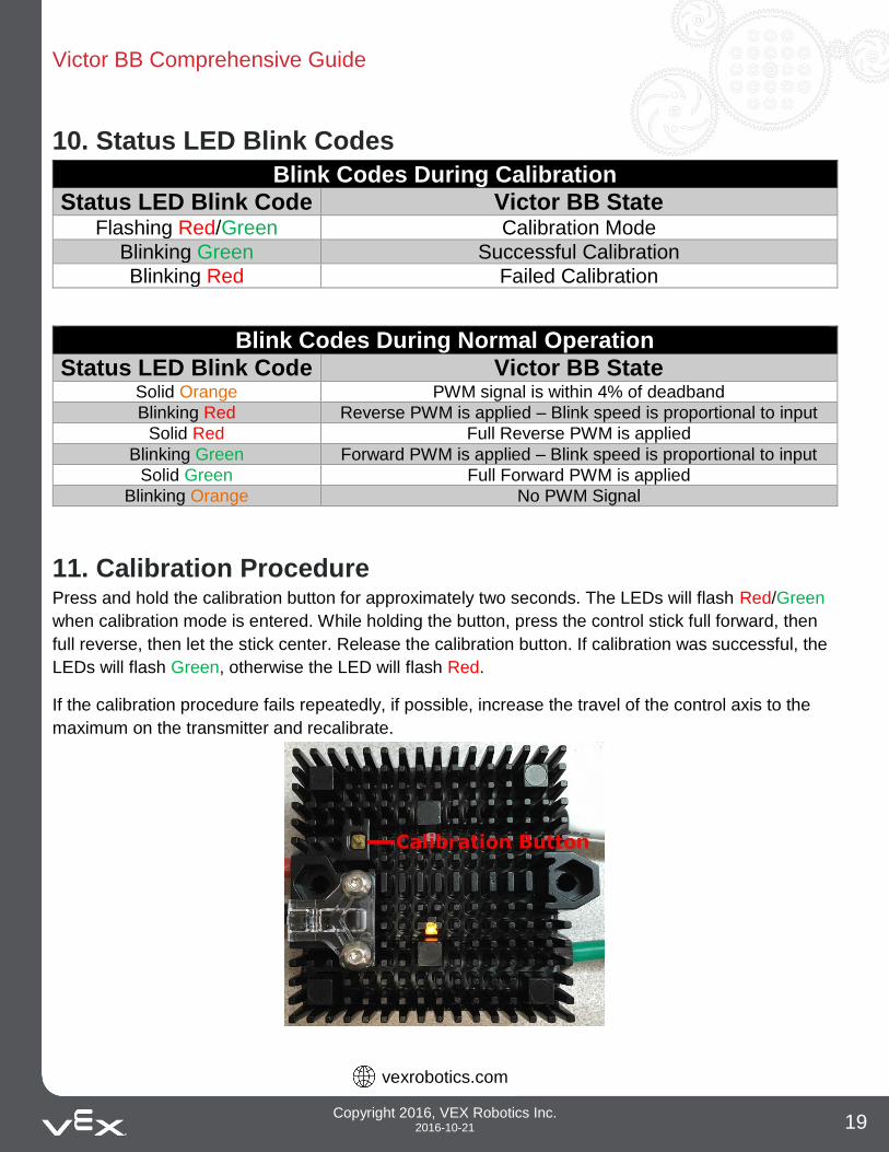
11. Calibration Procedure Press and hold the calibration button for approximately two seconds. The LEDs will flash Red/Green
when calibration mode is entered. While holding the button, press the control stick full forward, then
full reverse, then let the stick center. Release the calibration button. If calibration was successful, the
LEDs will flash Green, otherwise the LED will flash Red.
If the calibration procedure fails repeatedly, if possible, increase the travel of the control axis to the
maximum on the transmitter and recalibrate.
Victor BB Comprehensive Guide
vexrobotics.com
Copyright 2016, VEX Robotics Inc. 2016-10-21 20
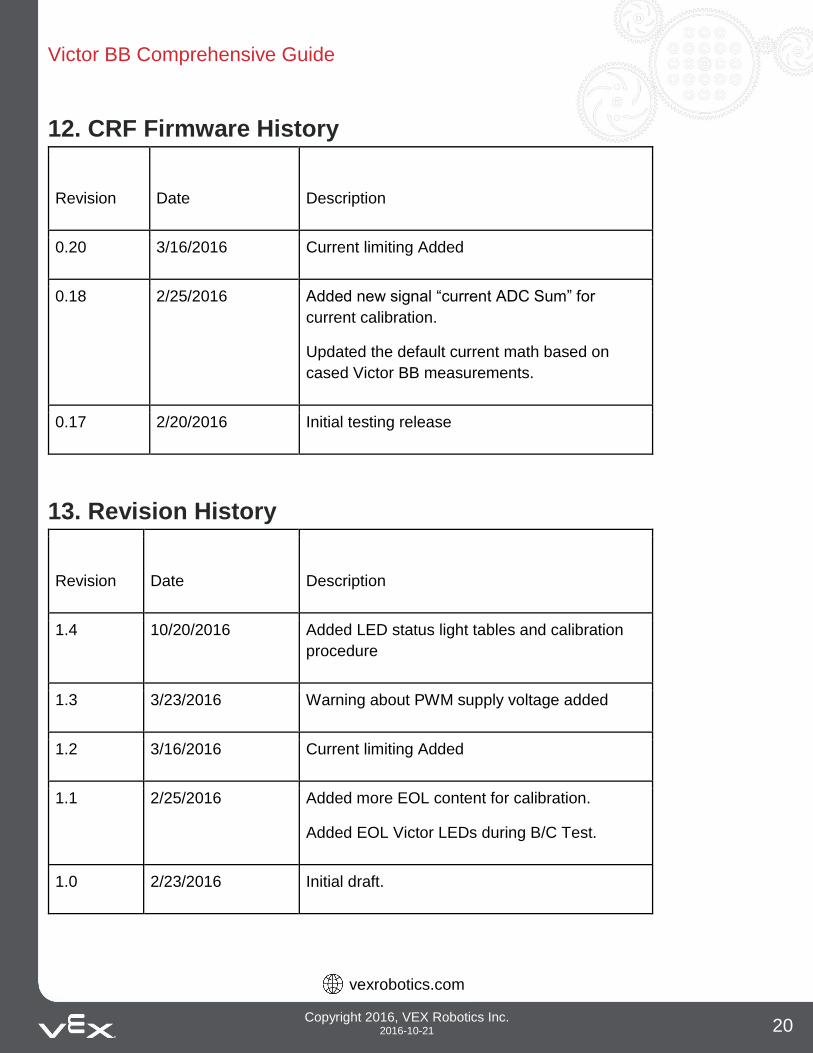
12. CRF Firmware History
Revision
Date
Description
0.20 3/16/2016 Current limiting Added
0.18 2/25/2016 Added new signal “current ADC Sum” for
current calibration.
Updated the default current math based on
cased Victor BB measurements.
0.17 2/20/2016 Initial testing release
13. Revision History
Revision
Date
Description
1.4 10/20/2016 Added LED status light tables and calibration
procedure
1.3 3/23/2016 Warning about PWM supply voltage added
1.2 3/16/2016 Current limiting Added
1.1 2/25/2016 Added more EOL content for calibration.
Added EOL Victor LEDs during B/C Test.
1.0 2/23/2016 Initial draft.