Embed Size (px)
Citation preview
5127.02/EN/0999/A
Fixed & variable displacement high pressure piston pumps350 bar (5000 psi)PF, PV – 20 Design, Open Loop Pumps066 cm3/r (4.03 in3/r) to 250 cm3/r (15.2 in3/r)
Vickers®
Piston Pumps
2
Contents
Introduction 3. . . . . . . . . . . . . . . . . . . . . . . . . . . . . . . . . . . . . . . . . . . . . . . . . . . . . . . . . . . . . . . . . . . . . . . . . . . . . . . . . . . . . General Description 3. . . . . . . . . . . . . . . . . . . . . . . . . . . . . . . . . . . . . . . . . . . . . . . . . . . . . . . . . . . . . . . . . . . . . . . . . . . . Features and Benefits 3. . . . . . . . . . . . . . . . . . . . . . . . . . . . . . . . . . . . . . . . . . . . . . . . . . . . . . . . . . . . . . . . . . . . . . . . . . . Performance 3. . . . . . . . . . . . . . . . . . . . . . . . . . . . . . . . . . . . . . . . . . . . . . . . . . . . . . . . . . . . . . . . . . . . . . . . . . . . . . . . . . Application 3. . . . . . . . . . . . . . . . . . . . . . . . . . . . . . . . . . . . . . . . . . . . . . . . . . . . . . . . . . . . . . . . . . . . . . . . . . . . . . . . . . . .
Pump Model Codes 4. . . . . . . . . . . . . . . . . . . . . . . . . . . . . . . . . . . . . . . . . . . . . . . . . . . . . . . . . . . . . . . . . . . . . . . . . . . . . . . Control Model Codes 6. . . . . . . . . . . . . . . . . . . . . . . . . . . . . . . . . . . . . . . . . . . . . . . . . . . . . . . . . . . . . . . . . . . . . . . . . . . . . . Specifications 7. . . . . . . . . . . . . . . . . . . . . . . . . . . . . . . . . . . . . . . . . . . . . . . . . . . . . . . . . . . . . . . . . . . . . . . . . . . . . . . . . . . .
General 7. . . . . . . . . . . . . . . . . . . . . . . . . . . . . . . . . . . . . . . . . . . . . . . . . . . . . . . . . . . . . . . . . . . . . . . . . . . . . . . . . . . . . . Hydraulic characteristics 7. . . . . . . . . . . . . . . . . . . . . . . . . . . . . . . . . . . . . . . . . . . . . . . . . . . . . . . . . . . . . . . . . . . . . . . . . Drive 7. . . . . . . . . . . . . . . . . . . . . . . . . . . . . . . . . . . . . . . . . . . . . . . . . . . . . . . . . . . . . . . . . . . . . . . . . . . . . . . . . . . . . . . .
Functional Symbol & Control Schematics 8. . . . . . . . . . . . . . . . . . . . . . . . . . . . . . . . . . . . . . . . . . . . . . . . . . . . . . . . . . . . . Performance Characteristics 8. . . . . . . . . . . . . . . . . . . . . . . . . . . . . . . . . . . . . . . . . . . . . . . . . . . . . . . . . . . . . . . . . . . . . . . Shaft Input Power 8. . . . . . . . . . . . . . . . . . . . . . . . . . . . . . . . . . . . . . . . . . . . . . . . . . . . . . . . . . . . . . . . . . . . . . . . . . . . . . . . . Operating Data 14. . . . . . . . . . . . . . . . . . . . . . . . . . . . . . . . . . . . . . . . . . . . . . . . . . . . . . . . . . . . . . . . . . . . . . . . . . . . . . . . . . .
Theoretical Bearing Life 14. . . . . . . . . . . . . . . . . . . . . . . . . . . . . . . . . . . . . . . . . . . . . . . . . . . . . . . . . . . . . . . . . . . . . . . . . Performance characteristics of variable displacement pumps 15. . . . . . . . . . . . . . . . . . . . . . . . . . . . . . . . . . . . . . . . . . . . LR controls; characteristics and calculations 16. . . . . . . . . . . . . . . . . . . . . . . . . . . . . . . . . . . . . . . . . . . . . . . . . . . . . . . . . Performance Calculations 16. . . . . . . . . . . . . . . . . . . . . . . . . . . . . . . . . . . . . . . . . . . . . . . . . . . . . . . . . . . . . . . . . . . . . . . . Typical drain flow from an open-loop pump 17. . . . . . . . . . . . . . . . . . . . . . . . . . . . . . . . . . . . . . . . . . . . . . . . . . . . . . . . . .
Installation Dimensions
PF 066 18. . . . . . . . . . . . . . . . . . . . . . . . . . . . . . . . . . . . . . . . . . . . . . . . . . . . . . . . . . . . . . . . . . . . . . . . . . . . . . . . . . . . . . PF 090 19. . . . . . . . . . . . . . . . . . . . . . . . . . . . . . . . . . . . . . . . . . . . . . . . . . . . . . . . . . . . . . . . . . . . . . . . . . . . . . . . . . . . . . . PF 130 – 180 20. . . . . . . . . . . . . . . . . . . . . . . . . . . . . . . . . . . . . . . . . . . . . . . . . . . . . . . . . . . . . . . . . . . . . . . . . . . . . . . . . . PF 250 21. . . . . . . . . . . . . . . . . . . . . . . . . . . . . . . . . . . . . . . . . . . . . . . . . . . . . . . . . . . . . . . . . . . . . . . . . . . . . . . . . . . . . . . PV 066 – 250 Rear Ports 22. . . . . . . . . . . . . . . . . . . . . . . . . . . . . . . . . . . . . . . . . . . . . . . . . . . . . . . . . . . . . . . . . . . . . . . . PV 066 – 250 Side Ports 26. . . . . . . . . . . . . . . . . . . . . . . . . . . . . . . . . . . . . . . . . . . . . . . . . . . . . . . . . . . . . . . . . . . . . . . .
Thru-Drive Mounting Dimensions 42. . . . . . . . . . . . . . . . . . . . . . . . . . . . . . . . . . . . . . . . . . . . . . . . . . . . . . . . . . . . . . . . . . . . SAE 4-Bolt Mounting Pads 43. . . . . . . . . . . . . . . . . . . . . . . . . . . . . . . . . . . . . . . . . . . . . . . . . . . . . . . . . . . . . . . . . . . . . . . . . Thru-drive Shaft Output Torque 43. . . . . . . . . . . . . . . . . . . . . . . . . . . . . . . . . . . . . . . . . . . . . . . . . . . . . . . . . . . . . . . . . . . . . Installation data 43. . . . . . . . . . . . . . . . . . . . . . . . . . . . . . . . . . . . . . . . . . . . . . . . . . . . . . . . . . . . . . . . . . . . . . . . . . . . . . . . . . Application Data
Case flushing requirements 44. . . . . . . . . . . . . . . . . . . . . . . . . . . . . . . . . . . . . . . . . . . . . . . . . . . . . . . . . . . . . . . . . . . . . .
Flushing flow 44. . . . . . . . . . . . . . . . . . . . . . . . . . . . . . . . . . . . . . . . . . . . . . . . . . . . . . . . . . . . . . . . . . . . . . . . . . Special fluids 44. . . . . . . . . . . . . . . . . . . . . . . . . . . . . . . . . . . . . . . . . . . . . . . . . . . . . . . . . . . . . . . . . . . . . . . . . . . . . . . . . . Fluid Cleanliness 44. . . . . . . . . . . . . . . . . . . . . . . . . . . . . . . . . . . . . . . . . . . . . . . . . . . . . . . . . . . . . . . . . . . . . . . . . . . . . . . Ordering Procedure 44. . . . . . . . . . . . . . . . . . . . . . . . . . . . . . . . . . . . . . . . . . . . . . . . . . . . . . . . . . . . . . . . . . . . . . . . . . . . .
� Vickers, Incorporated 1999
All Rights Reserved
3
Introduction
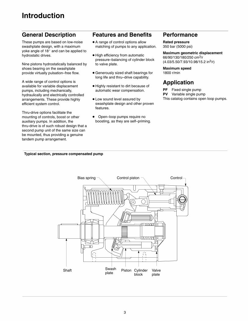
General DescriptionThese pumps are based on low-noiseswashplate design, with a maximumyoke angle of 18� and can be applied tohydrostatic drives.
Nine pistons hydrostatically balanced byshoes bearing on the swashplateprovide virtually pulsation–free flow.
A wide range of control options isavailable for variable displacementpumps, including mechanically,hydraulically and electrically controlledarrangements. These provide highlyefficient system control.
Thru-drive options facilitate themounting of controls, boost or otherauxiliary pumps. In addition, thethru-drive is of such robust design that asecond pump unit of the same size canbe mounted, thus providing a genuinetandem pump arrangement.
Features and Benefits� A range of control options allow
matching of pumps to any application.
� High efficiency from automaticpressure–balancing of cylinder blockto valve plate.
� Generously sized shaft bearings forlong life and thru–drive capability.
� Highly resistant to dirt because ofautomatic wear compensation.
� Low sound level assured byswashplate design and other provenfeatures.
� Open–loop pumps require noboosting, as they are self–priming.
PerformanceRated pressure350 bar (5000 psi)
Maximum geometric displacement66/90/130/180/250 cm3/r(4.03/5.50/7.93/10.98/15.2 in3/r)
Maximum speed1800 r/min
ApplicationPF Fixed single pumpPV Variable single pumpThis catalog contains open loop pumps.
Typical section, pressure compensated pump
Bias spring Control piston Control
Shaft Piston Cylinderblock
Valveplate
Swashplate
4
Model Codes
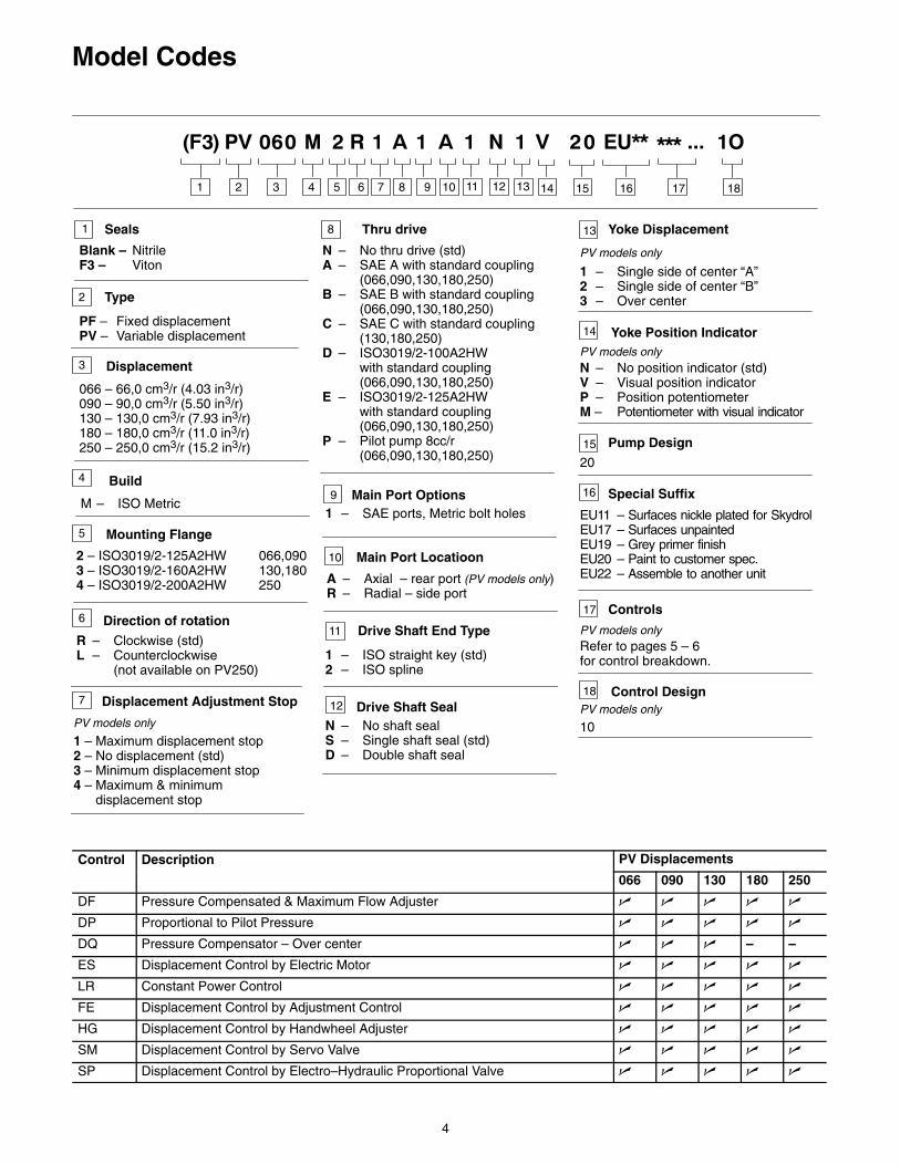
PF – Fixed displacementPV – Variable displacement
1 2 3 4 5 6 7 8 9 10
1
Type2
Displacement
066 – 66,0 cm3/r (4.03 in3/r)090 – 90,0 cm3/r (5.50 in3/r)130 – 130,0 cm3/r (7.93 in3/r)180 – 180,0 cm3/r (11.0 in3/r)250 – 250,0 cm3/r (15.2 in3/r)
3
Build
M – ISO Metric
4
Direction of rotation
R – Clockwise (std)L – Counterclockwise
(not available on PV250)
5
6
Thru drive
N – No thru drive (std)A – SAE A with standard coupling
(066,090,130,180,250)B – SAE B with standard coupling
(066,090,130,180,250)C – SAE C with standard coupling
(130,180,250)D – ISO3019/2-100A2HW
with standard coupling(066,090,130,180,250)
E – ISO3019/2-125A2HWwith standard coupling(066,090,130,180,250)
P – Pilot pump 8cc/r(066,090,130,180,250)
9 Main Port Options1 – SAE ports, Metric bolt holes
Controls
11 12 13 14 15 16 17
Seals
Blank – NitrileF3 – Viton
Mounting Flange
2 – ISO3019/2-125A2HW3 – ISO3019/2-160A2HW4 – ISO3019/2-200A2HW
066,090130,180250
Displacement Adjustment Stop
1 – Maximum displacement stop2 – No displacement (std)3 – Minimum displacement stop4 – Maximum & minimum displacement stop
7
8
10
A – Axial – rear port (PV models only)R – Radial – side port
Main Port Locatioon
11
1 – ISO straight key (std)2 – ISO spline
Drive Shaft End Type
12
N – No shaft sealS – Single shaft seal (std)D – Double shaft seal
Drive Shaft Seal
16
17
10
Control Design
...
18
EU11 – Surfaces nickle plated for SkydrolEU17 – Surfaces unpaintedEU19 – Grey primer finishEU20 – Paint to customer spec.EU22 – Assemble to another unit
Special Suffix
18
Refer to pages 5 – 6for control breakdown.
Yoke Position Indicator
N – No position indicator (std)V – Visual position indicatorP – Position potentiometerM – Potentiometer with visual indicator
15
20
Pump Design
13
1 – Single side of center “A”2 – Single side of center “B”3 – Over center
Yoke Displacement
14
PV models only
PV models only
PV models only
PV models only
PV models only
Control Description PV Displacementsp
066 090 130 180 250
DF Pressure Compensated & Maximum Flow Adjuster � � � � �
DP Proportional to Pilot Pressure � � � � �
DQ Pressure Compensator – Over center � � � – –
ES Displacement Control by Electric Motor � � � � �
LR Constant Power Control � � � � �
FE Displacement Control by Adjustment Control � � � � �
HG Displacement Control by Handwheel Adjuster � � � � �
SM Displacement Control by Servo Valve � � � � �
SP Displacement Control by Electro–Hydraulic Proportional Valve � � � � �

5
Model Codes
DF ControlPressure Compensator & Maximum Flow Adjuster
1 – Direct operated (std)2 – Pilot operated
Maximum Flow AdjustmentF – Screw adjuster (std)H – Handwheel
Compensator Pressure Setting
090 – Std setting 90 bar (1300 psi)xxx – Customer requested setting
Compensator ControlR – Remote connection port only
(std)F – Screw adjuster on compensator
(std)K – Electro-proportional relief valve
Pressure Limiting Valve Operator1 – No solenoid valve (std)2 – Solenoid unloading valve
Solenoid Control VoltageN – No solenoidA – 110VAC50HzB – 110VAC50Hz / 120 VAC60 HzC – 220VAC50HzD – 220VAC50Hz / 240VAC60HzG – 12VDCH – 24VDC
Load Sensing1 – No load sensing (std)2 – Load sensing
DF 1 F 090 R 1 N 1 10Example of DF model:
DP Control Displacement ControlProportional to pilot pressure
Power ControlN – No power control
1 – Mounting interface only (std)2 – Pilot relief & remote port3 – Pilot relief, remote port &
proportional relief (1-S/S)4 – Pilot relief, remote port &
proportional relief (2-S/S)
Power ControlN – No power control
Pressure Limiter1 – Without pressure limiter (std)2 – With pressure limiter
Pressure Limiting Valve OperationA – Single side of center (std)B – Over center
Solenoid Control VoltageN – No solenoidA – 110VAC50HzB – 110VAC50Hz / 120 VAC60 HzC – 220VAC50HzD – 220VAC50Hz / 240VAC60HzG – 12VDCH – 24VDC
DQ ControlPressure Compensator Over Center
A – Mounted on controlB – Remote connection only (std)
Method of Operation1 – Direct operated (std)2 – Pilot operated
Solenoid Unloading Valve
N – No solenoid unloading valve (std)V – Solenoid unloading valve
Compensator Pressure Setting090 – Std setting 90 bar (1300 psi)xxx – Customer requested setting
Solenoid Control VoltageN – No solenoidA – 110VAC50HzB – 110VAC50Hz / 120 VAC60 HzC – 220VAC50HzD – 220VAC50Hz / 240VAC60HzG – 12VDCH – 24VDC
DP 1 N 1 A N 10Example of DP model:
DQ B 1 N 090 N 10Example of DQ model:
17 17 17
1 2 3 4 5 6 7 8 9 10 11 12 13 14 15 16 17
...
18
6
Model Codes
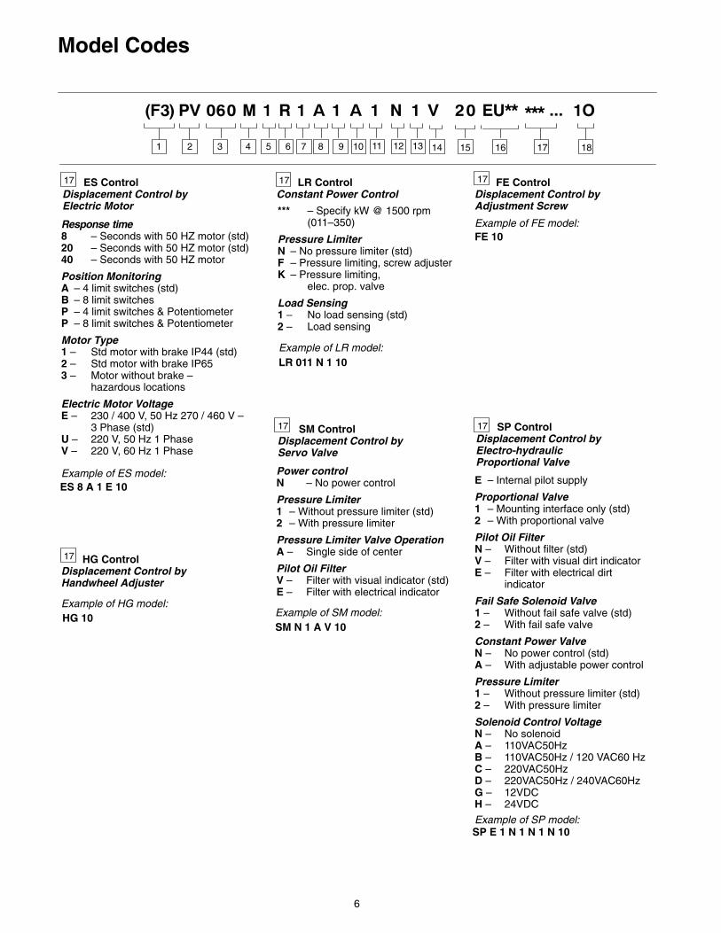
ES ControlDisplacement Control byElectric Motor
Response time8 – Seconds with 50 HZ motor (std)20 – Seconds with 50 HZ motor (std)40 – Seconds with 50 HZ motor
Position MonitoringA – 4 limit switches (std)B – 8 limit switchesP – 4 limit switches & PotentiometerP – 8 limit switches & Potentiometer
Motor Type1 – Std motor with brake IP44 (std)2 – Std motor with brake IP653 – Motor without brake –
hazardous locations
Electric Motor VoltageE – 230 / 400 V, 50 Hz 270 / 460 V –
3 Phase (std)U – 220 V, 50 Hz 1 PhaseV – 220 V, 60 Hz 1 Phase
SM N 1 A V 10Example of SM model:
LR ControlConstant Power Control
*** – Specify kW @ 1500 rpm (011–350)
Pressure LimiterN – No pressure limiter (std)F – Pressure limiting, screw adjusterK – Pressure limiting,
elec. prop. valve
Load Sensing1 – No load sensing (std)2 – Load sensing
HG ControlDisplacement Control byHandwheel Adjuster
FE ControlDisplacement Control byAdjustment Screw
SM Control Displacement Control byServo Valve
Power controlN – No power control
Pressure Limiter1 – Without pressure limiter (std)2 – With pressure limiter
Pressure Limiter Valve OperationA – Single side of center
Pilot Oil FilterV – Filter with visual indicator (std)E – Filter with electrical indicator
E – Internal pilot supply
Proportional Valve1 – Mounting interface only (std)2 – With proportional valve
Pilot Oil FilterN – Without filter (std)V – Filter with visual dirt indicatorE – Filter with electrical dirt
indicator
Fail Safe Solenoid Valve1 – Without fail safe valve (std)2 – With fail safe valve
Constant Power ValveN – No power control (std)A – With adjustable power control
Pressure Limiter1 – Without pressure limiter (std)2 – With pressure limiter
Solenoid Control VoltageN – No solenoidA – 110VAC50HzB – 110VAC50Hz / 120 VAC60 HzC – 220VAC50HzD – 220VAC50Hz / 240VAC60HzG – 12VDCH – 24VDC
SP Control Displacement Control byElectro-hydraulicProportional Valve
ES 8 A 1 E 10Example of ES model:
LR 011 N 1 10Example of LR model:
FE 10Example of FE model:
HG 10Example of HG model:
SP E 1 N 1 N 1 N 10Example of SP model:
17 17 17
1717
17
1 2 3 4 5 6 7 8 9 10 11 12 13 14 15 16 17
...
18
7
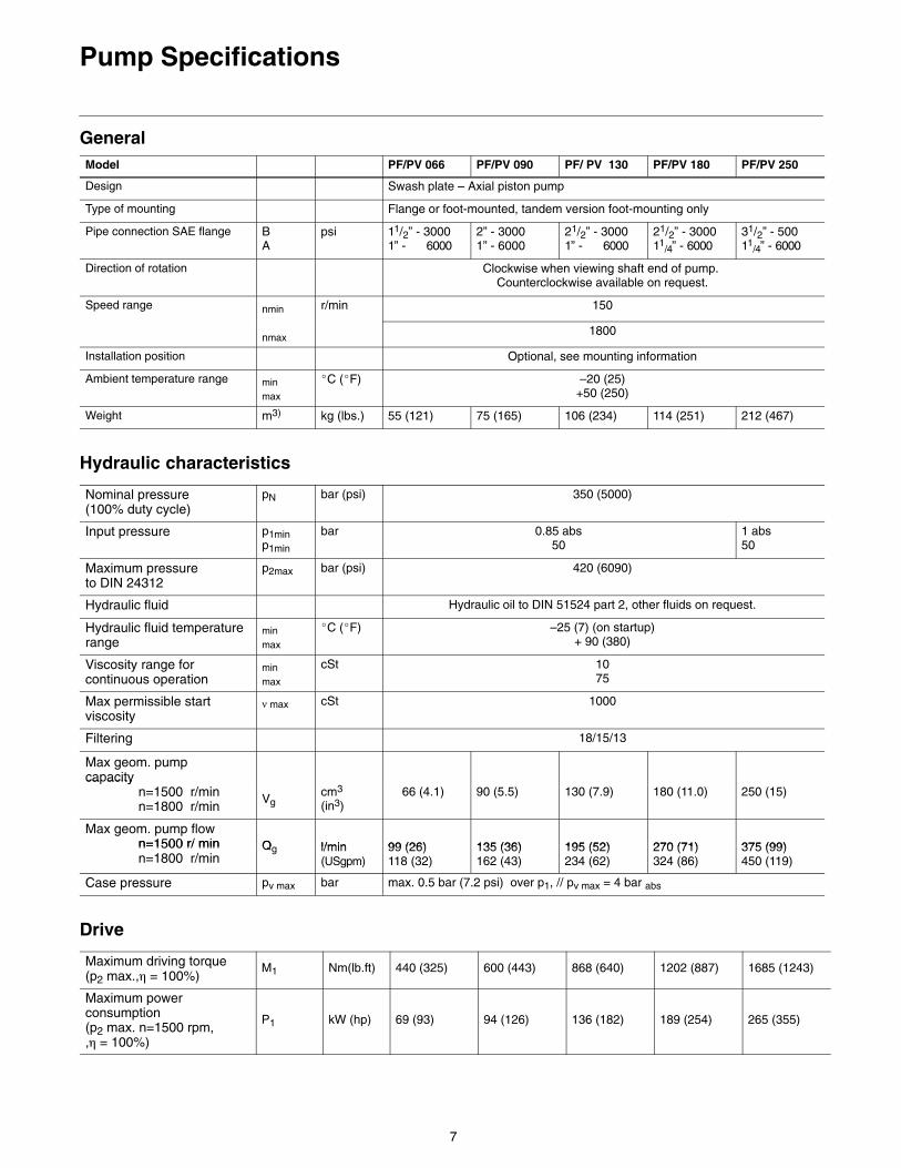
Pump Specifications
General Model PF/PV 066 PF/PV 090 PF/ PV 130 PF/PV 180 PF/PV 250
Design Swash plate – Axial piston pump
Type of mounting Flange or foot-mounted, tandem version foot-mounting only
Pipe connection SAE flange BA
psi 11/2” - 30001” - 6000
2” - 30001” - 6000
21/2” - 30001” - 6000
21/2” - 300011
/4” - 600031/2” - 50011
/4” - 6000
Direction of rotation Clockwise when viewing shaft end of pump. Counterclockwise available on request.
Speed range nmin r/min 150
nmax1800
Installation position Optional, see mounting information
Ambient temperature range minmax
�C (�F) –20 (25)+50 (250)
Weight m3) kg (lbs.) 55 (121) 75 (165) 106 (234) 114 (251) 212 (467)
Hydraulic characteristics
Nominal pressure (100% duty cycle)
pN bar (psi) 350 (5000)
Input pressure p1minp1min
bar 0.85 abs50
1 abs50
Maximum pressure to DIN 24312
p2max bar (psi) 420 (6090)
Hydraulic fluid Hydraulic oil to DIN 51524 part 2, other fluids on request.
Hydraulic fluid temperaturerange
minmax
�C (�F) –25 (7) (on startup)+ 90 (380)
Viscosity range forcontinuous operation
minmax
cSt 1075
Max permissible startviscosity
ν max cSt 1000
Filtering 18/15/13
Max geom. pumpcapacity
3ca acity
n=1500 r/minn=1800 r/min
Vgcm3
(in3)66 (4.1) 90 (5.5) 130 (7.9) 180 (11.0) 250 (15)
Max geom. pump flown=1500 r/ min Q l/min 99 (26) 135 (36) 195 (52) 270 (71) 375 (99)n=1500 r/ minn=1800 r/min
Qg l/min(USgpm)
99 (26)118 (32)
135 (36)162 (43)
195 (52)234 (62)
270 (71)324 (86)
375 (99)450 (119)
Case pressure pv max bar max. 0.5 bar (7.2 psi) over p1, // pv max = 4 bar abs
Drive
Maximum driving torque(p2 max.,� = 100%)
M1 Nm(lb.ft) 440 (325) 600 (443) 868 (640) 1202 (887) 1685 (1243)
Maximum powerconsumption(p2 max. n=1500 rpm, ,� = 100%)
P1 kW (hp) 69 (93) 94 (126) 136 (182) 189 (254) 265 (355)
8
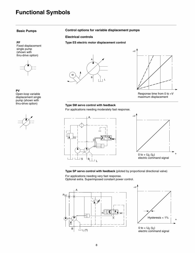
Functional Symbols
Basic Pumps
PFFixed displacementsingle pump(shown withthru-drive option)
PVOpen-loop variabledisplacement singlepump (shown withthru-drive option)
Control options for variable displacement pumps
Electrical controls
Type ES electric motor displacement control
M
Response time from 0 to +V maximum displacement
+V
A
BL
+
+V
0 to + UE (IE) electric command signalS B
L
A
For applications needing moderately fast response.
Type SM servo control with feedback
+
+V
0 to + UE (IE)electric command signal
Hysteresis < 1%
PST
BL
A
Type SP servo control with feedback (piloted by proportional directional valve)
For applications needing very fast response. Optional extra. Superimposed constant power control.
(T)
9
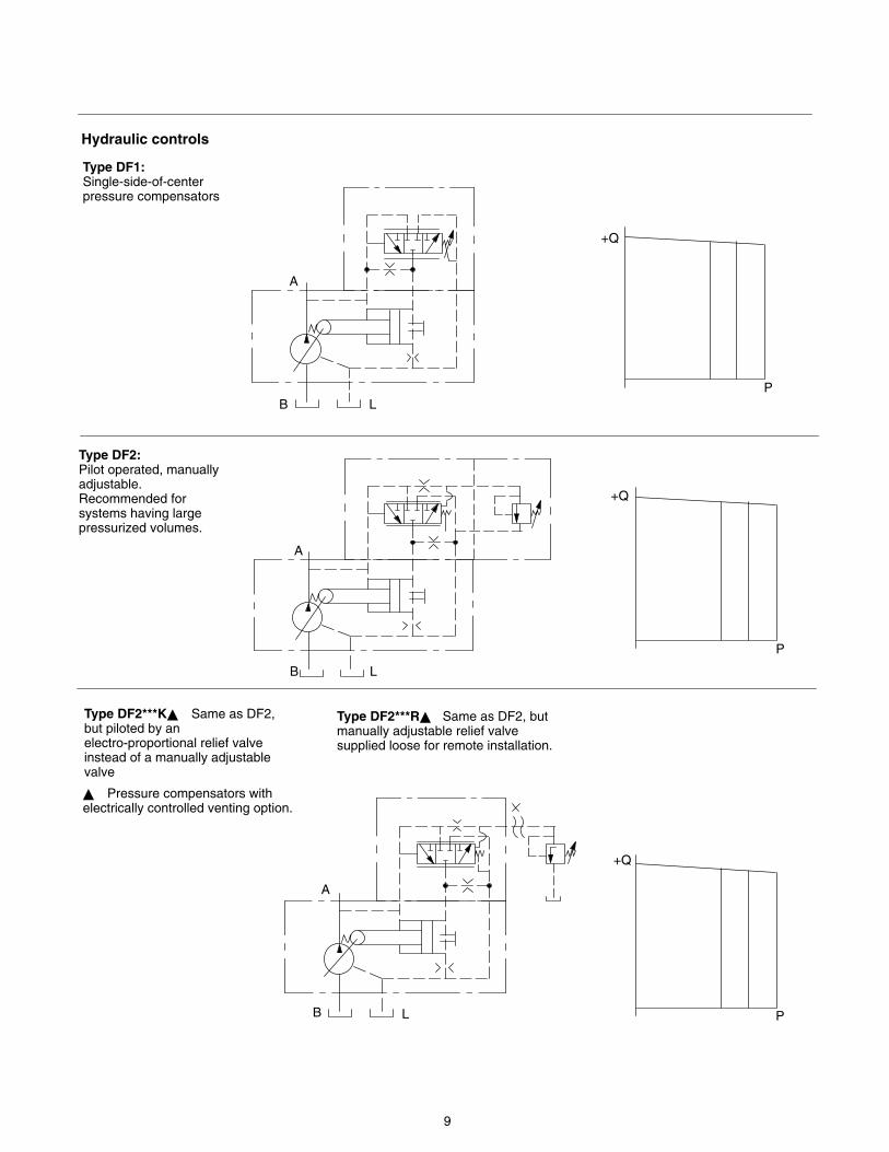
Type DF1:Single-side-of-centerpressure compensators
A
B L
+Q
P
Type DF2:Pilot operated, manuallyadjustable.Recommended forsystems having largepressurized volumes.
A
B L
+Q
P
Type DF2***K� Same as DF2,but piloted by anelectro-proportional relief valveinstead of a manually adjustablevalve
A
B L
+Q
P
Type DF2***R� Same as DF2, butmanually adjustable relief valvesupplied loose for remote installation.
� Pressure compensators withelectrically controlled venting option.
Hydraulic controls
10
Functional Symbols
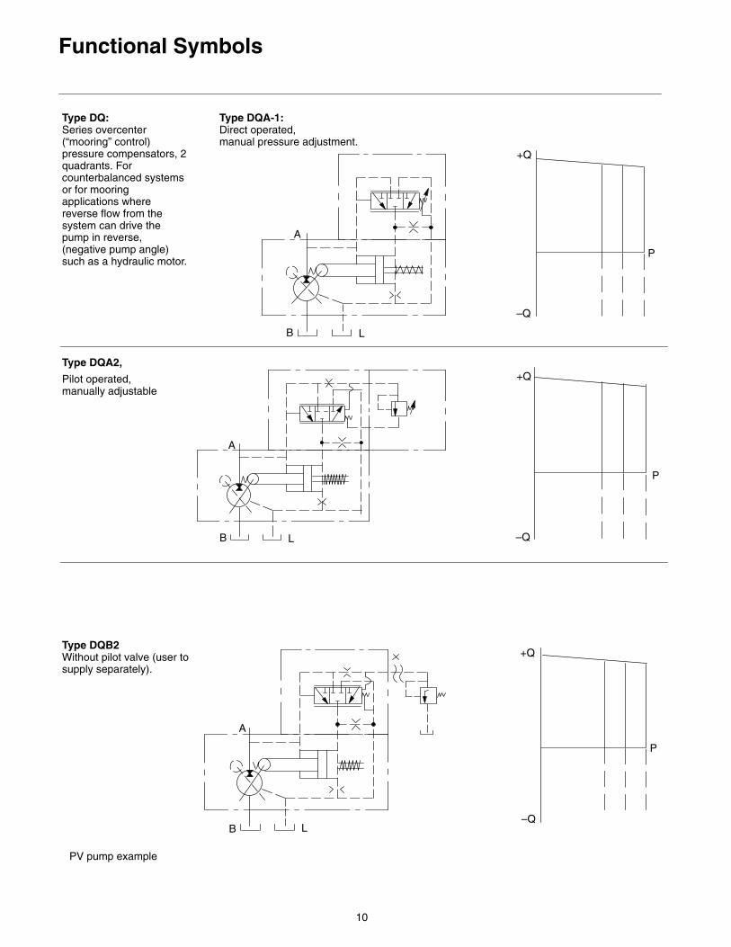
Type DQ:Series overcenter(“mooring” control)pressure compensators, 2quadrants. Forcounterbalanced systemsor for mooringapplications wherereverse flow from thesystem can drive thepump in reverse,(negative pump angle)such as a hydraulic motor.
A
B L
+Q
P
PV pump example
Type DQA-1:Direct operated, manual pressure adjustment.
–Q
Type DQA2,
Pilot operated,manually adjustable
A
B L
+Q
P
–Q
+Q
P
–Q
Type DQB2Without pilot valve (user tosupply separately).
A
B L
11
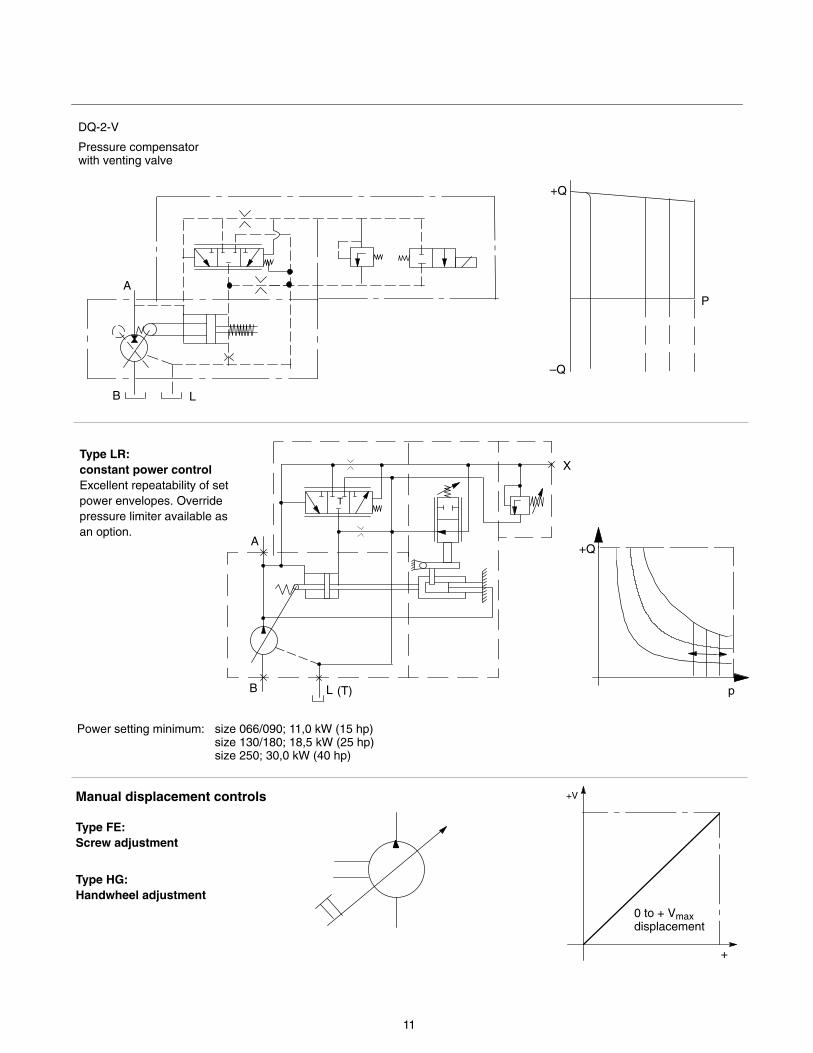
DQ-2-V
+Q
p
Type LR:constant power controlExcellent repeatability of setpower envelopes. Overridepressure limiter available asan option.
A
B L
T
X
Power setting minimum: size 066/090; 11,0 kW (15 hp)size 130/180; 18,5 kW (25 hp)size 250; 30,0 kW (40 hp)
Pressure compensatorwith venting valve
Manual displacement controls
Type FE:Screw adjustment
Type HG:Handwheel adjustment
+
+V
0 to + Vmaxdisplacement
(T)
A
B L
+Q
P
–Q
12
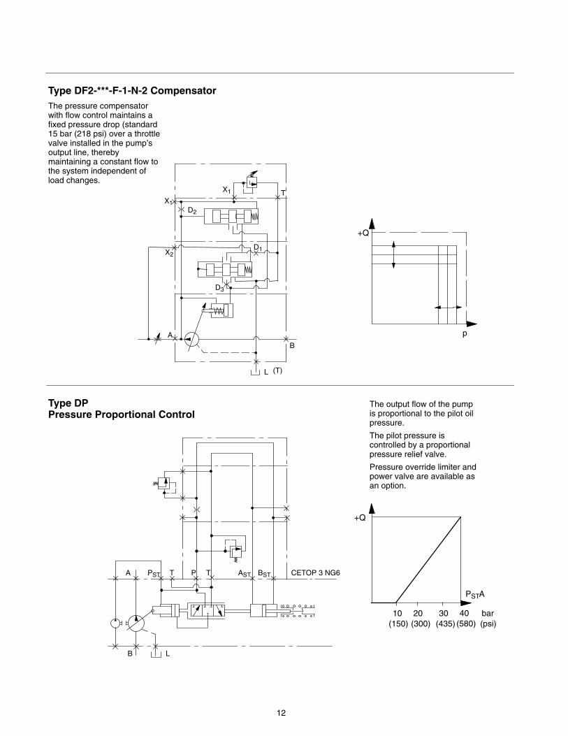
Type DF2-***-F-1-N-2 Compensator
B
L
TX1
A
The pressure compensatorwith flow control maintains afixed pressure drop (standard15 bar (218 psi) over a throttlevalve installed in the pump’soutput line, therebymaintaining a constant flow tothe system independent ofload changes.
X1D2
D1X2
D3
+Q
p
Type DP Pressure Proportional Control
The output flow of the pumpis proportional to the pilot oilpressure.
The pilot pressure iscontrolled by a proportionalpressure relief valve.
Pressure override limiter andpower valve are available asan option.
B L
A PST T P T AST BST CETOP 3 NG6
+Q
PSTA
10 20 30 bar(150) (300) (435) (psi)
(T)
40(580)
13
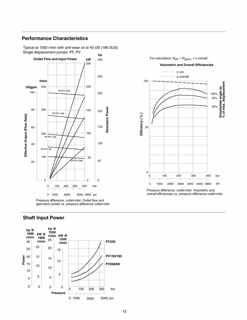
Performance Characteristics
Typical at 1500 r/min with anti-wear oil at 40 cSt (186 SUS)Single displacement pumps: PF, PV
Outlet Flow and Input Power
100 200 300 4000
Eff
ecti
ve O
utp
ut
(Flo
w R
ate)
Geo
met
ric
Po
wer
kW250
200
150
100
50
0
100
200
300
USgpm
l/min
hp
Eff
icie
ncy
( %
)
300
250
200
150
100
50
0
350
η vol.η overall
100
50
0100 200 300 400
1000
0
0 2000 3000 4000 5000 5800
bar
psi
25%
50%
100%
0
20
40
60
80
400
Volumetric and Overall Efficiencies
0 1000 3000 5000 5800
bar
psi
100 PF/PV 250
Sw
ash
pla
te a
ng
le a
s%
of
max
. dis
pla
cem
ent
PF/PV 066
PF/PV 130
PF/PV 90
Pressure difference, outlet-inlet. Volumetric andoverall efficiencies vs. pressure difference outlet-inlet.
Pressure difference, outlet-inlet. Outlet flow andgeometric power vs. pressure difference outlet-inlet.
For calculation: Neff. = Ngeom. � η overall
PF/PV 180
Po
wer
bar
psi
0 100 200 300
1000 3000 5000
0 0 0 0
5
10
15
20
25
30
5
10
15
20
5
10
15
20
25
5
10
15
PV250
PV130/180
PV066/90
0
Pressure
hp @1800r/min
kW @1800r/min
hp @1500r/min kW @
1500r/min
Shaft Input Power
14
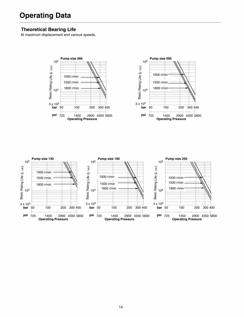
Operating Data
Theoretical Bearing Life
Pump size 066
At maximum displacement and various speeds.
50 100 200 300 400
725 1450 2900 4350 5800Operating Pressure
bar
psi
104
105
1000 r/min
1500 r/min
1800 r/min
Pump size 090
50 100 200 300 400
725 1450 2900 4350 5800Operating Pressure
bar
psi
104
105
1000 r/min
1500 r/min
1800 r/min
Pump size 130
50 100 200 300 400
725 1450 2900 4350 5800Operating Pressure
bar
psi
104
105
1000 r/min
1500 r/min
1800 r/min
Pump size 180
50 100 200 300 400
725 1450 2900 4350 5800Operating Pressure
bar
psi
104
105
1000 r/min
1500 r/min1800 r/min
Pump size 250
50 100 200 300 400
725 1450 2900 4350 5800Operating Pressure
bar
psi
104
105
1000 r/min
1500 r/min
1800 r/min
3 x 10³ 3 x 10³
3 x 10³ 3 x 10³ 3 x 10³
15
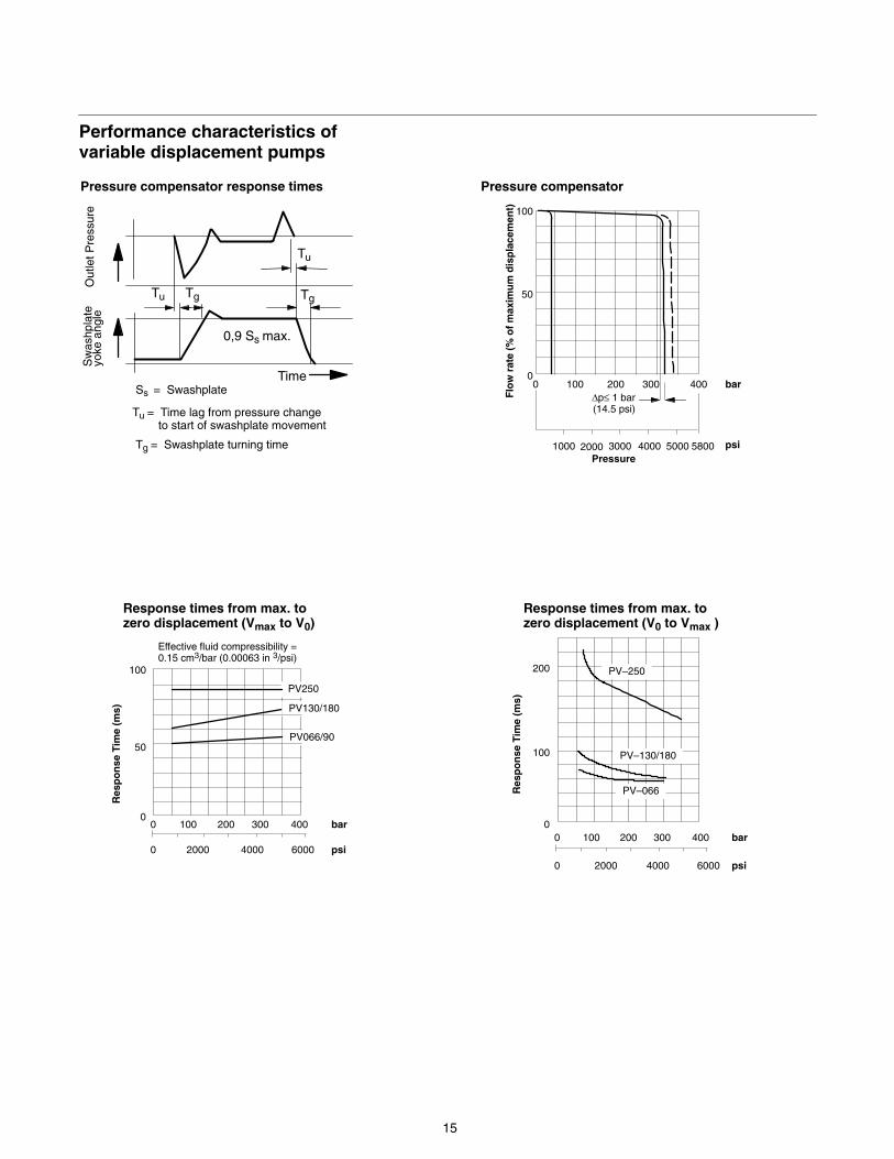
Performance characteristics ofvariable displacement pumps
100
50
00 100 200 400300
1000 3000 4000 5000 5800
bar
psi
∆p≤ 1 bar(14.5 psi)
Flo
w r
ate
(% o
f m
axim
um
dis
pla
cem
ent)
Pressure compensator
Pressure
Response times from max. tozero displacement (Vmax to V0)
Effective fluid compressibility =0.15 cm3/bar (0.00063 in 3/psi)
0 100 200 300 400
2000 4000 6000
bar
psi
50
0
100
PV130/180
PV066/90
00 100 200 300 400
2000 4000 6000
bar
psi0
0
100
200
Res
po
nse
Tim
e (m
s)
Res
po
nse
Tim
e (m
s)
Response times from max. tozero displacement (V0 to Vmax )
PV–250
PV–130/180
PV–066
PV250
Pressure compensator response times
Sw
ashp
late
yoke
ang
leO
utle
t Pre
ssur
e
Tu Tg
Tu
Tg
Time
0,9 Ss max.
Ss = Swashplate
Tu = Time lag from pressure change to start of swashplate movement
Tg = Swashplate turning time 2000
16
0
5
10
15
20
25
30
0 100 200 3000
5
10
15
20
25
30
35
40hp kW
22
18.5
11
1000 2000 3000 4000 5000 psi
Example
∆P
7.5
bar
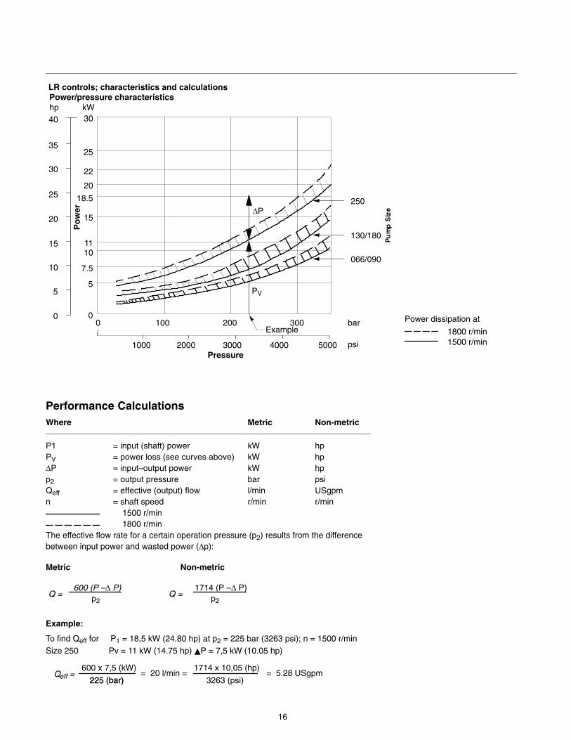
LR controls; characteristics and calculations Power/pressure characteristics
250
130/180
066/090
Power dissipation at
1800 r/min1500 r/min
Pressure
Po
wer
PV
Performance Calculations Where Metric Non-metric
P1 = input (shaft) power kW hpPV = power loss (see curves above) kW hp∆P = input–output power kW hpp2 = output pressure bar psiQeff = effective (output) flow l/min USgpmn = shaft speed r/min r/min
1500 r/min 1800 r/min
The effective flow rate for a certain operation pressure (p2) results from the difference between input power and wasted power (∆p):
Metric Non-metric
600 (P –∆ P)p2
1714 (P –∆ P)p2
Q =Q =
Example:
To find Qeff for P1 = 18,5 kW (24.80 hp) at p2 = 225 bar (3263 psi); n = 1500 r/minSize 250 Pv = 11 kW (14.75 hp) �P = 7,5 kW (10.05 hp)
600 x 7,5 (kW)Qeff = 225 (bar)
= 20 l/min =1714 x 10,05 (hp)
225 (bar) 3263 (psi)= 5.28 USgpm
17
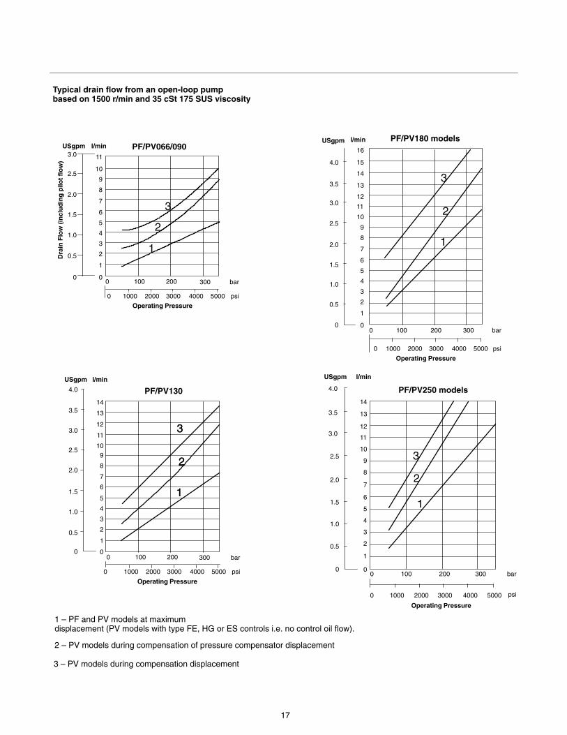
Typical drain flow from an open-loop pumpbased on 1500 r/min and 35 cSt 175 SUS viscosity
Dra
in F
low
(in
clu
din
g p
ilot
flo
w)
PF/PV066/090USgpm l/min
0
1
2
3
4
5
6
7
8
9
10
11
0
0.5
1.0
1.5
2.0
2.5
3.0
1
0 100 200 300
1000 2000 3000 4000 5000
bar
psi
0
1
2
3
4
5
6
7
8
9
10
11
12
13
14
0
0.5
1.0
1.5
2.0
2.5
3.0
3.5
4.0
USgpm l/min
0 100 200 300
1000 2000 3000 4000 5000
bar
psi
Operating Pressure
0
3 – PV models during compensation displacement
Operating Pressure
1 – PF and PV models at maximum displacement (PV models with type FE, HG or ES controls i.e. no control oil flow).
PF/PV130
0 100 200 300
1000 2000 3000 4000 50000
bar
psi
0
1
2
3
4
5
6
7
8
9
10
11
12
13
14
0
0.5
1.0
1.5
2.0
2.5
3.0
3.5
4.0
Operating Pressure
USgpm l/min
15
16
PF/PV180 models
0 100 200 300
1000 2000 3000 4000 50000
bar
psi
0
1
2
3
4
5
6
7
8
9
10
11
12
13
14
0
0.5
1.0
1.5
2.0
2.5
3.0
3.5
4.0
Operating Pressure
PF/PV250 models
USgpm l/min
2 – PV models during compensation of pressure compensator displacement
0
2
3
1
2
3
1
2
3
1
2
3
1
2
3
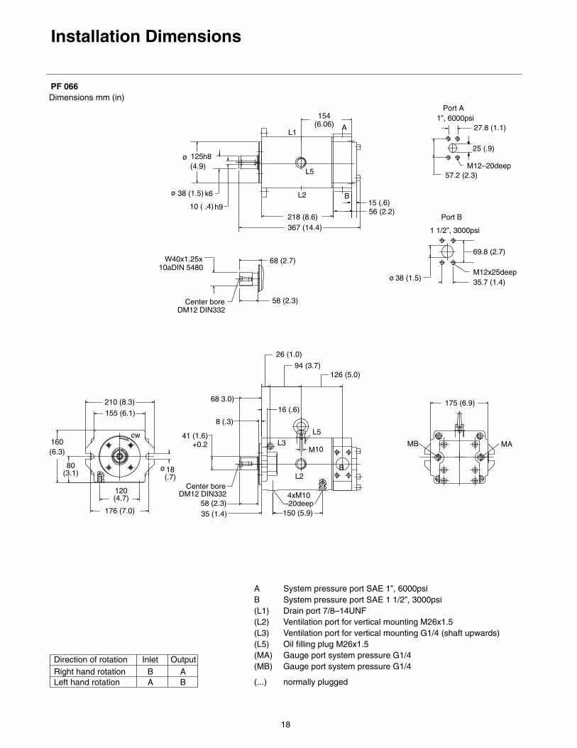
18
Installation Dimensions
Dimensions mm (in)PF 066
+0.2
56 (2.2)
367 (14.4)218 (8.6)
M10
150 (5.9)
4xM10–20deep
L2
System pressure port SAE 1”, 6000psiSystem pressure port SAE 1 1/2”, 3000psiDrain port 7/8–14UNFVentilation port for vertical mounting M26x1.5Ventilation port for vertical mounting G1/4 (shaft upwards)Oil filling plug M26x1.5Gauge port system pressure G1/4Gauge port system pressure G1/4
Right hand rotationDirection of rotation
Left hand rotation
AB(L1)(L2)(L3)(L5)(MA)(MB)
BA
InletAB
Output
normally plugged(...)
ø 125 (4.9)
ø 38 (1.5)
h8
k6
10 ( .4)h9
L1
175 (6.9)
MB
16 (.6)
8 (.3)
68 3.0)
MA
35 (1.4)
68 (2.7)
58 (2.3)
W40x1.25x
DM12 DIN332Center bore
10aDIN 5480
58 (2.3)DM12 DIN332
Center bore
41 (1.6)
L2
L3
27.8 (1.1)
25 (.9)
1 1/2”, 3000psi
Port B
35.7 (1.4)
15 (.6)B
L5
A
ø 38 (1.5)
57.2 (2.3)
69.8 (2.7)
M12x25deep
M12–20deep
210 (8.3)
155 (6.1)
176 (7.0)
120(4.7)
Port A1”, 6000psi
L5
B
160(6.3)
80(3.1)
ø18(.7)
cw
154(6.06)
26 (1.0)
94 (3.7)126 (5.0)
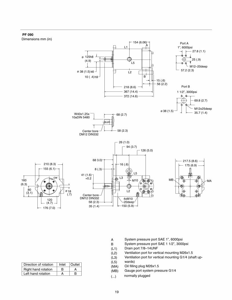
19
Dimensions mm (in)PF 090
+0.2
56 (2.2)
372 (14.6)
218 (8.6)
M10
150 (5.9)
4xM10–20deep
L2
System pressure port SAE 1”, 6000psiSystem pressure port SAE 1 1/2”, 3000psiDrain port 7/8–14UNFVentilation port for vertical mounting M26x1.5Ventilation port for vertical mounting G1/4 (shaft up-wards)Oil filling plug M26x1.5Gauge port system pressure G1/4Right hand rotation
Direction of rotation
Left hand rotation
AB(L1)(L2)(L3)(L5)(MA)(MB)
BA
InletAB
Outlet
normally plugged(...)
ø 125 (4.9)
ø 38 (1.5)
h8
k6
10 ( .4)h9
L1
MB
16 (.6)
8 (.3)
68 3.0)
MA
35 (1.4)
68 (2.7)
58 (2.3)
W40x1.25x
DM12 DIN332Center bore
10aDIN 5480
58 (2.3)DM12 DIN332
Center bore
41 (1.6)
L2
L3
27.8 (1.1)
25 (.9)
1 1/2”, 3000psi
Port B
35.7 (1.4)
15 (.6)B
L5
A
ø 38 (1.5)
57.2 (2.3)
69.8 (2.7)
M12x25deep
M12–20deep
210 (8.3)
155 (6.1)
176 (7.0)
120(4.7)
Port A1”, 6000psi
L5
160(6.3)
80(3.1)
ø18(.7)
cw
154 (6.06)
26 (1.0)
94 (3.7)126 (5.0)
B
367 (14.4)
175 (6.9)217.5 (8.6)
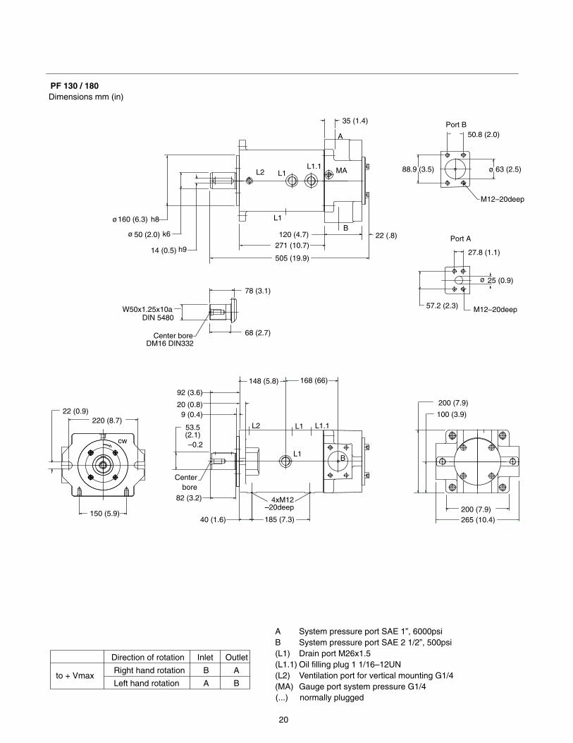
20
Dimensions mm (in)PF 130 / 180
14 (0.5) h9505 (19.9)
271 (10.7)
185 (7.3)
DM16 DIN332
ø 50 (2.0)
ø160 (6.3) h8
k6
L1
L2 L1
265 (10.4)200 (7.9)
200 (7.9)
100 (3.9)
92 (3.6)
20 (0.8)
Center bore
53.5(2.1)
DIN 5480W50x1.25x10a
Centerbore
40 (1.6)
78 (3.1)
68 (2.7)
82 (3.2)
–0.2
4xM12–20deep
9 (0.4)
L2
35 (1.4)
88.9 (3.5) ø 63 (2.5)
Port A
ø 25 (0.9)
27.8 (1.1)
22 (.8)120 (4.7)B
MAL1.1
A
57.2 (2.3) M12–20deep
M12–20deep
cw
Port B50.8 (2.0)
150 (5.9)
220 (8.7)
L1 B
22 (0.9)
L1.1L1
System pressure port SAE 1”, 6000psiSystem pressure port SAE 2 1/2”, 500psiDrain port M26x1.5Oil filling plug 1 1/16–12UNVentilation port for vertical mounting G1/4Gauge port system pressure G1/4
Direction of rotation
Right hand rotation
Left hand rotationto + Vmax
AB(L1)(L1.1)(L2)(MA)
Outlet
A
Inlet
B
B
A
(...) normally plugged
148 (5.8) 168 (66)
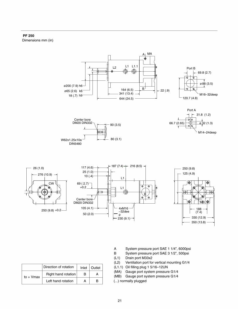
21
Dimensions mm (in)PF 250
L1
230 (9.1)
4xM16–32deep
341 (13.4)
System pressure port SAE 1 1/4”, 6000psiSystem pressure port SAE 3 1/2”, 500psiDrain port M33x2Ventilation port for vertical mounting G1/4Oil filling plug 1 5/16–12UNGauge port system pressure G1/4Gauge port system pressure G1/4
644 (24.5)
OutletDirection of rotation
Right hand rotation
Left hand rotationto + Vmax
A
Inlet
B
AB(L1)(L2)(L1.1)(MA)(MB)
B
A
(...) normally plugged
ø65 (2.6)
ø200 (7.9) h6
18 (.7) h9k6
L2
350 (13.8)
330 (12.9)
188(7.4)
250 (9.8)
125 (4.9)
117 (4.6)
W62x1.25x10a
DM20 DIN332
Center boreDM20 DIN332 MB
90 (3.5)
80 (3.1)
DIN5480
Center bore
105 (4.1)
69 ( 2.7)+0.2
50 (2.0)
L1
10 (.4)25 (1.0)
L1
69.8 (2.7)
ø88 (3.5)
31.8 (1.2)
ø 32 (1.3)
22 (.9)164 (6.5) B
L1.1
MAA
66.7 (2.65)
120.7 (4.8)
Port A
M14–24deep
M16–32deep
Port B
276 (10.9)
B
26 (1.0)
250 (9.8) +0.2
CW
187 (7.4) 216 (8.5)
22
M18x1,5–12deep
+0.2
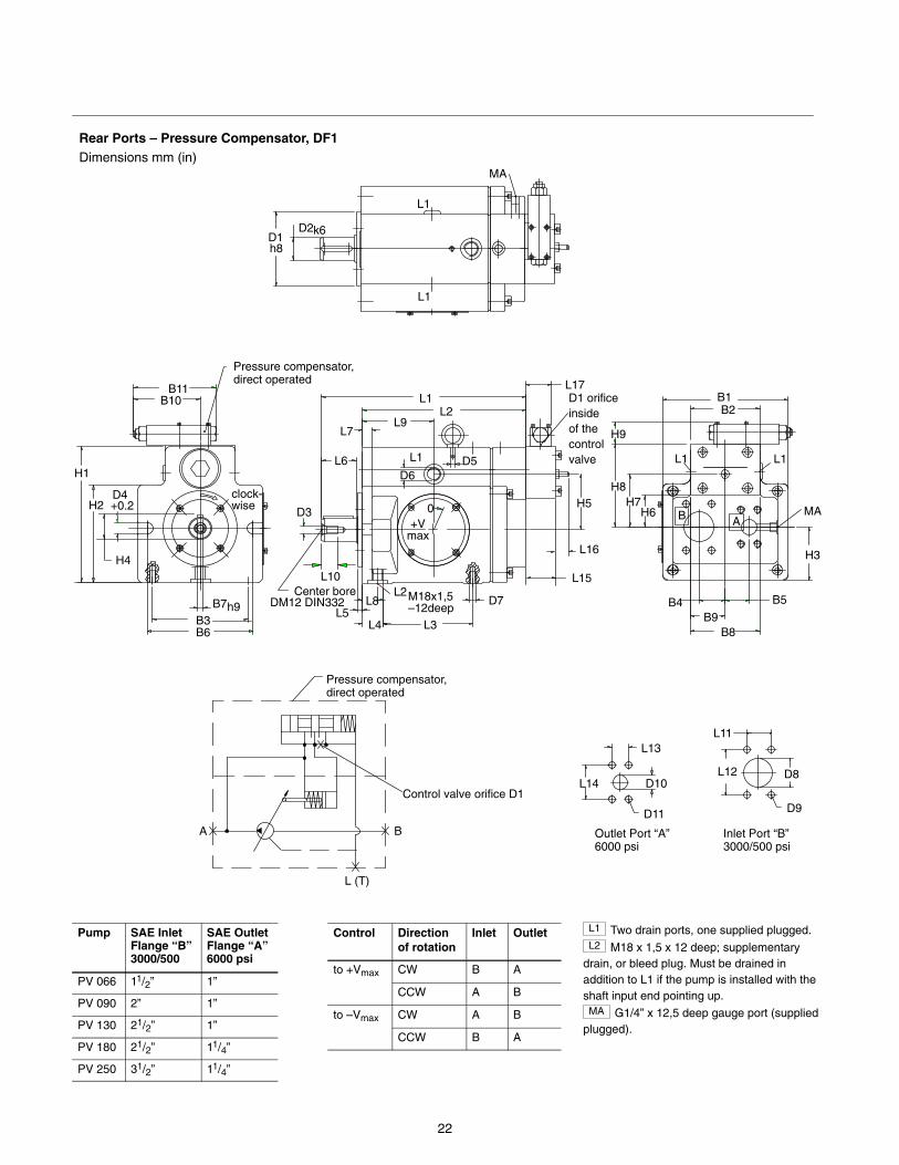
Rear Ports – Pressure Compensator, DF1Dimensions mm (in)
Inlet Port “B” 3000/500 psi
Outlet Port “A” 6000 psi
L12
L11
D9
L (T)
BA
Control valve orifice D1
Pressure compensator,direct operated
D8
L10
L6
D1
L1
H1
B1
k6
h8
D2
H2B
H3
B4 B5Center bore
DM12 DIN332
AD3 MA
L1 L1
B2
B7
B6
D6
L7
H5
B3
L1
L1
L3
L8
L4L5
L2D7
0+V
max
MA
D4
H4
clock-wise
L9L2
L1 D5
h9
L17
L15
L16
B10B11
H6H7
H8
H9
B8B9
D1 orificeinside of thecontrolvalve
Pressure compensator,direct operated
L13
D10L14
D11
Pump SAE InletFlange “B”3000/500
SAE OutletFlange “A”6000 psi
PV 066 11/2” 1”
PV 090 2” 1”
PV 130 21/2” 1”
PV 180 21/2” 11/4”
PV 250 31/2” 11/4”
Control Directionof rotation
Inlet Outlet
to +Vmax CW B A
CCW A B
to –Vmax CW A B
CCW B A
L1 Two drain ports, one supplied plugged.L2 M18 x 1,5 x 12 deep; supplementary
drain, or bleed plug. Must be drained inaddition to L1 if the pump is installed with theshaft input end pointing up.MA G1/4” x 12,5 deep gauge port (supplied
plugged).
23
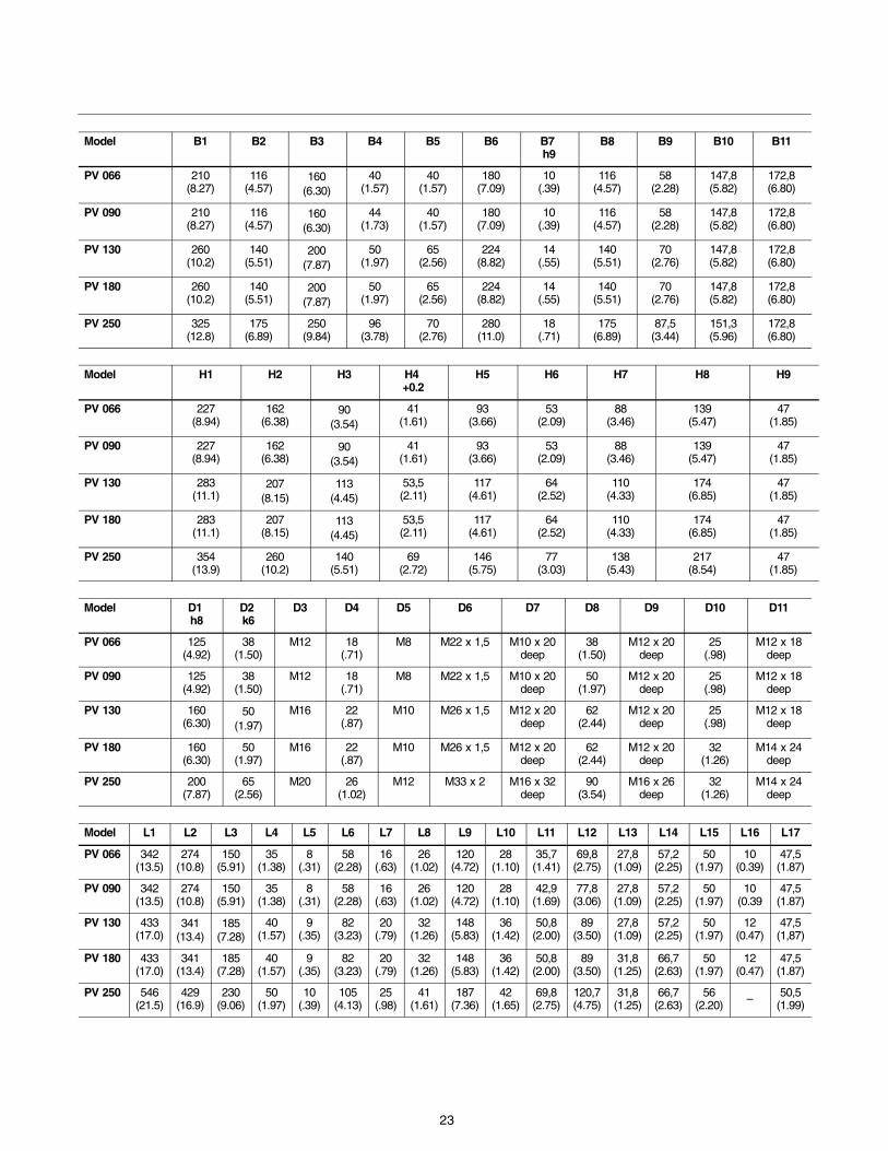
Model B1 B2 B3 B4 B5 B6 B7 h9
B8 B9 B10 B11
PV 066 210(8.27)
116(4.57)
160(6.30)
40(1.57)
40(1.57)
180(7.09)
10(.39)
116(4.57)
58(2.28)
147,8(5.82)
172,8(6.80)
PV 090 210(8.27)
116(4.57)
160(6.30)
44(1.73)
40(1.57)
180(7.09)
10(.39)
116(4.57)
58(2.28)
147,8(5.82)
172,8(6.80)
PV 130 260(10.2)
140(5.51)
200(7.87)
50(1.97)
65(2.56)
224(8.82)
14(.55)
140(5.51)
70(2.76)
147,8(5.82)
172,8(6.80)
PV 180 260(10.2)
140(5.51)
200(7.87)
50(1.97)
65(2.56)
224(8.82)
14(.55)
140(5.51)
70(2.76)
147,8(5.82)
172,8(6.80)
PV 250 325(12.8)
175(6.89)
250(9.84)
96(3.78)
70(2.76)
280(11.0)
18(.71)
175(6.89)
87,5(3.44)
151,3(5.96)
172,8(6.80)
Model H1 H2 H3 H4 +0.2
H5 H6 H7 H8 H9
PV 066 227(8.94)
162(6.38)
90(3.54)
41(1.61)
93(3.66)
53(2.09)
88(3.46)
139(5.47)
47(1.85)
PV 090 227(8.94)
162(6.38)
90(3.54)
41(1.61)
93(3.66)
53(2.09)
88(3.46)
139(5.47)
47(1.85)
PV 130 283(11.1)
207(8.15)
113(4.45)
53,5(2.11)
117(4.61)
64(2.52)
110(4.33)
174(6.85)
47(1.85)
PV 180 283(11.1)
207(8.15)
113(4.45)
53,5(2.11)
117(4.61)
64(2.52)
110(4.33)
174(6.85)
47(1.85)
PV 250 354(13.9)
260(10.2)
140(5.51)
69(2.72)
146(5.75)
77(3.03)
138(5.43)
217(8.54)
47(1.85)
Model D1 h8
D2 k6
D3 D4 D5 D6 D7 D8 D9 D10 D11
PV 066 125(4.92)
38(1.50)
M12 18(.71)
M8 M22 x 1,5 M10 x 20deep
38(1.50)
M12 x 20deep
25(.98)
M12 x 18deep
PV 090 125(4.92)
38(1.50)
M12 18(.71)
M8 M22 x 1,5 M10 x 20deep
50(1.97)
M12 x 20deep
25(.98)
M12 x 18deep
PV 130 160(6.30)
50(1.97)
M16 22(.87)
M10 M26 x 1,5 M12 x 20deep
62(2.44)
M12 x 20deep
25(.98)
M12 x 18deep
PV 180 160(6.30)
50(1.97)
M16 22(.87)
M10 M26 x 1,5 M12 x 20deep
62(2.44)
M12 x 20deep
32(1.26)
M14 x 24deep
PV 250 200(7.87)
65(2.56)
M20 26(1.02)
M12 M33 x 2 M16 x 32deep
90(3.54)
M16 x 26deep
32(1.26)
M14 x 24deep
Model L1 L2 L3 L4 L5 L6 L7 L8 L9 L10 L11 L12 L13 L14 L15 L16 L17
PV 066 342(13.5)
274(10.8)
150(5.91)
35(1.38)
8(.31)
58(2.28)
16(.63)
26(1.02)
120(4.72)
28(1.10)
35,7(1.41)
69,8(2.75)
27,8(1.09)
57,2(2.25)
50(1.97)
10(0.39)
47,5(1.87)
PV 090 342(13.5)
274(10.8)
150(5.91)
35(1.38)
8(.31)
58(2.28)
16(.63)
26(1.02)
120(4.72)
28(1.10)
42,9(1.69)
77,8(3.06)
27,8(1.09)
57,2(2.25)
50(1.97)
10(0.39
47,5(1.87)
PV 130 433(17.0)
341(13.4)
185(7.28)
40(1.57)
9(.35)
82(3.23)
20(.79)
32(1.26)
148(5.83)
36(1.42)
50,8(2.00)
89(3.50)
27,8(1.09)
57,2(2.25)
50(1.97)
12(0.47)
47,5(1,87)
PV 180 433(17.0)
341(13.4)
185(7.28)
40(1.57)
9(.35)
82(3.23)
20(.79)
32(1.26)
148(5.83)
36(1.42)
50,8(2.00)
89(3.50)
31,8(1.25)
66,7(2.63)
50(1.97)
12(0.47)
47,5(1.87)
PV 250 546(21.5)
429(16.9)
230(9.06)
50(1.97)
10(.39)
105(4.13)
25(.98)
41(1.61)
187(7.36)
42(1.65)
69,8(2.75)
120,7(4.75)
31,8(1.25)
66,7(2.63)
56(2.20) – 50,5
(1.99)
24
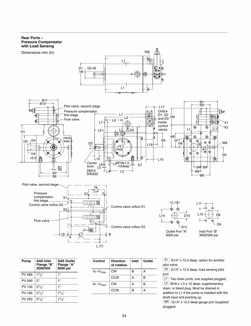
Rear Ports –Pressure Compensatorwith Load Sensing
Dimensions mm (in)
Inlet Port “B” 3000/500 psi
Outlet Port “A” 6000 psi
L12
L11
D9
D8
OrificeD1, D2and D3insidecontrolvalves
Pressure compensator,first stage
Pilot valve, second stage
Control valve orifice D1
L (T)
BA
T
Pilot valve, second stage
Pressure compensator, first stage
X1
X2
Control valve orifice D3
Flow valve
Control valve orifice D2
X1
Flow valve
H8
B1
H7MA
H3
B9B4
B8
H6 B
B5
A
H9
B2
L1 L1
X1X2
D1 D2h8
k6
L1
L1
MA
L9L2
L3
M18x1,5–12deep
D6
L1
L7
L6
L10
D3
L4L5L8 L2
0
L1
H5
D7
+Vmax
L15
L16
D5
L17
CenterboreDM12DIN332
H1
H4
B6B3
H2 D4
B7h9
clockwise
+0.2
B11B10
L14
L13
D10
D11
Pump SAE InletFlange “B”3000/500
SAE OutletFlange “A”6000 psi
PV 066 11/2” 1”
PV 090 2” 1”
PV 130 21/2” 1”
PV 180 21/2” 11/4”
PV 250 31/2” 11/4”
Control Directionof rotation
Inlet Outlet
to +Vmax CW B A
CCW A B
to –Vmax CW A B
CCW B A
X1 G1/4” x 12,5 deep; option for anotherpilot valve.X2 G1/4” x 12,5 deep; load sensing pilot
port.L1 Two drain ports, one supplied plugged.L2 M18 x 1,5 x 12 deep; supplementary
drain, or bleed plug. Must be drained inaddition to L1 if the pump is installed with theshaft input end pointing up.MA G1/4” x 12,5 deep gauge port (supplied
plugged).
25
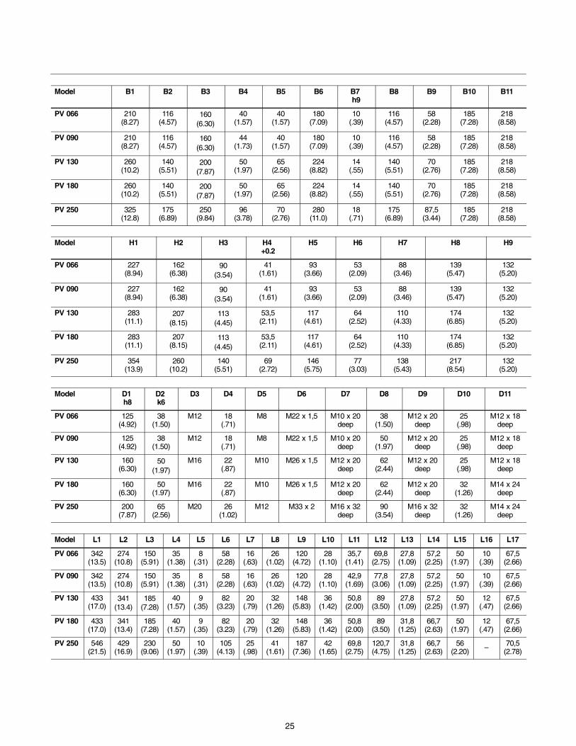
Model B1 B2 B3 B4 B5 B6 B7 h9
B8 B9 B10 B11
PV 066 210(8.27)
116(4.57)
160(6.30)
40(1.57)
40(1.57)
180(7.09)
10(.39)
116(4.57)
58(2.28)
185(7.28)
218(8.58)
PV 090 210(8.27)
116(4.57)
160(6.30)
44(1.73)
40(1.57)
180(7.09)
10(.39)
116(4.57)
58(2.28)
185(7.28)
218(8.58)
PV 130 260(10.2)
140(5.51)
200(7.87)
50(1.97)
65(2.56)
224(8.82)
14(.55)
140(5.51)
70(2.76)
185(7.28)
218(8.58)
PV 180 260(10.2)
140(5.51)
200(7.87)
50(1.97)
65(2.56)
224(8.82)
14(.55)
140(5.51)
70(2.76)
185(7.28)
218(8.58)
PV 250 325(12.8)
175(6.89)
250(9.84)
96(3.78)
70(2.76)
280(11.0)
18(.71)
175(6.89)
87,5(3.44)
185(7.28)
218(8.58)
Model H1 H2 H3 H4 +0.2
H5 H6 H7 H8 H9
PV 066 227(8.94)
162(6.38)
90(3.54)
41(1.61)
93(3.66)
53(2.09)
88(3.46)
139(5.47)
132(5.20)
PV 090 227(8.94)
162(6.38)
90(3.54)
41(1.61)
93(3.66)
53(2.09)
88(3.46)
139(5.47)
132(5.20)
PV 130 283(11.1)
207(8.15)
113(4.45)
53,5(2.11)
117(4.61)
64(2.52)
110(4.33)
174(6.85)
132(5.20)
PV 180 283(11.1)
207(8.15)
113(4.45)
53,5(2.11)
117(4.61)
64(2.52)
110(4.33)
174(6.85)
132(5.20)
PV 250 354(13.9)
260(10.2)
140(5.51)
69(2.72)
146(5.75)
77(3.03)
138(5.43)
217(8.54)
132(5.20)
Model D1 h8
D2 k6
D3 D4 D5 D6 D7 D8 D9 D10 D11
PV 066 125(4.92)
38(1.50)
M12 18(.71)
M8 M22 x 1,5 M10 x 20deep
38(1.50)
M12 x 20deep
25(.98)
M12 x 18deep
PV 090 125(4.92)
38(1.50)
M12 18(.71)
M8 M22 x 1,5 M10 x 20deep
50(1.97)
M12 x 20deep
25(.98)
M12 x 18deep
PV 130 160(6.30)
50(1.97)
M16 22(.87)
M10 M26 x 1,5 M12 x 20deep
62(2.44)
M12 x 20deep
25(.98)
M12 x 18deep
PV 180 160(6.30)
50(1.97)
M16 22(.87)
M10 M26 x 1,5 M12 x 20deep
62(2.44)
M12 x 20deep
32(1.26)
M14 x 24deep
PV 250 200(7.87)
65(2.56)
M20 26(1.02)
M12 M33 x 2 M16 x 32deep
90(3.54)
M16 x 32deep
32(1.26)
M14 x 24deep
Model L1 L2 L3 L4 L5 L6 L7 L8 L9 L10 L11 L12 L13 L14 L15 L16 L17
PV 066 342(13.5)
274(10.8)
150(5.91)
35(1.38)
8(.31)
58(2.28)
16(.63)
26(1.02)
120(4.72)
28(1.10)
35,7(1.41)
69,8(2.75)
27,8(1.09)
57,2(2.25)
50(1.97)
10(.39)
67,5(2.66)
PV 090 342(13.5)
274(10.8)
150(5.91)
35(1.38)
8(.31)
58(2.28)
16(.63)
26(1.02)
120(4.72)
28(1.10)
42,9(1.69)
77,8(3.06)
27,8(1.09)
57,2(2.25)
50(1.97)
10(.39)
67,5(2.66)
PV 130 433(17.0)
341(13.4)
185(7.28)
40(1.57)
9(.35)
82(3.23)
20(.79)
32(1.26)
148(5.83)
36(1.42)
50,8(2.00)
89(3.50)
27,8(1.09)
57,2(2.25)
50(1.97)
12(.47)
67,5(2.66)
PV 180 433(17.0)
341(13.4)
185(7.28)
40(1.57)
9(.35)
82(3.23)
20(.79)
32(1.26)
148(5.83)
36(1.42)
50,8(2.00)
89(3.50)
31,8(1.25)
66,7(2.63)
50(1.97)
12(.47)
67,5(2.66)
PV 250 546(21.5)
429(16.9)
230(9.06)
50(1.97)
10(.39)
105(4.13)
25(.98)
41(1.61)
187(7.36)
42(1.65)
69,8(2.75)
120,7(4.75)
31,8(1.25)
66,7(2.63)
56(2.20) – 70,5
(2.78)
26
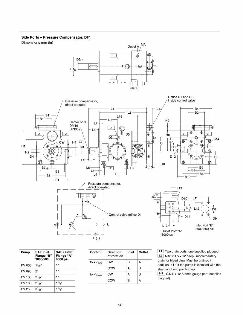
Side Ports – Pressure Compensator, DF1Dimensions mm (in)
D1h8
D2k6
MA
L1
L1
H1
H2
H4 +0,2
D4
B6B3
B7h9
H8
H9
H3
Inlet Port “B” 3000/500 psi
Outlet Port “A” 6000 psi
L12
L11
D9
L (T)
BA
B11B10
Orifice D1 and D2 inside control valve
Control valve orifice D1
Pressure compensator,direct operated
D8
B1
L1
L2
D3
Center bore DM16DIN332
L10
D6D5
D7
L3
L8L5
L4
L15L16
B
Outlet A
L6
L7L9
L18L2
L1 L17
H5 H7
H6
B12B5
B8B9
MA
B4B2
L1 L1
D12
Inlet B
L1
L1
L13
D11
D10
L14
L19
Pressure compensator,direct operated
CW
Pump SAE InletFlange “B”3000/500
SAE OutletFlange “A”6000 psi
PV 066 11/2” 1”
PV 090 2” 1”
PV 130 21/2” 1”
PV 180 21/2” 11/4”
PV 250 31/2” 11/4”
Control Directionof rotation
Inlet Outlet
to +Vmax CW B A
CCW A B
to –Vmax CW A B
CCW B A
L1 Two drain ports, one supplied plugged.L2 M18 x 1,5 x 12 deep; supplementary
drain, or bleed plug. Must be drained inaddition to L1 if the pump is installed with theshaft input end pointing up.MA G1/4” x 12,5 deep gauge port (supplied
plugged).
27
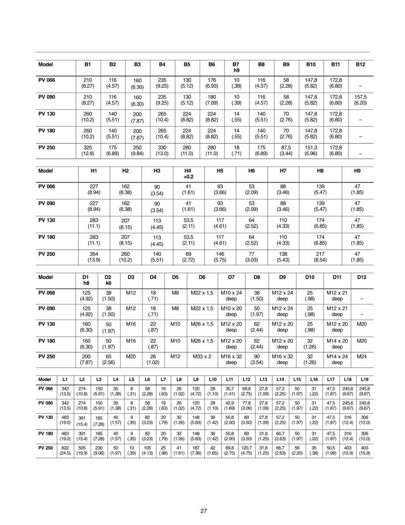
Model B1 B2 B3 B4 B5 B6 B7 h9
B8 B9 B10 B11 B12
PV 066 210(8.27)
116(4.57)
160(6.30)
235(9.25)
130(5.12)
176(6.93)
10(.39)
116(4.57)
58(2.28)
147,8(5.82)
172,8(6.80) –
PV 090 210(8.27)
116(4.57)
160(6.30)
235(9.25)
130(5.12)
180(7.09)
10(.39)
116(4.57)
58(2.28)
147,8(5.82)
172,8(6.80)
157,5(6.20)
PV 130 260(10.2)
140(5.51)
200(7.87)
265(10.4)
224(8.82)
224(8.82)
14(.55)
140(5.51)
70(2.76)
147,8(5.82)
172,8(6.80) –
PV 180 260(10.2)
140(5.51)
200(7.87)
265(10.4)
224(8.82)
224(8.82)
14(.55)
140(5.51)
70(2.76)
147,8(5.82)
172,8(6.80) –
PV 250 325(12.8)
175(6.89)
250(9.84)
330(13.0)
280(11.0)
280(11.0)
18(.71)
175(6.89)
87,5(3.44)
151,3(5.96)
172,8(6.80) –
Model H1 H2 H3 H4 +0.2
H5 H6 H7 H8 H9
PV 066 227(8.94)
162(6.38)
90(3.54)
41(1.61)
93(3.66)
53(2.09)
88(3.46)
139(5.47)
47(1.85)
PV 090 227(8.94)
162(6.38)
90(3.54)
41(1.61)
93(3.66)
53(2.09)
88(3.46)
139(5.47)
47(1.85)
PV 130 283(11.1)
207(8.15)
113(4.45)
53,5(2.11)
117(4.61)
64(2.52)
110(4.33)
174(6.85)
47(1.85)
PV 180 283(11.1)
207(8.15)
113(4.45)
53,5(2.11)
117(4.61)
64(2.52)
110(4.33)
174(6.85)
47(1.85)
PV 250 354(13.9)
260(10.2)
140(5.51)
69(2.72)
146(5.75)
77(3.03)
138(5.43)
217(8.54)
47(1.85)
Model D1 h8
D2 k6
D3 D4 D5 D6 D7 D8 D9 D10 D11 D12
PV 066 125(4.92)
38(1.50)
M12 18(.71)
M8 M22 x 1,5 M10 x 24deep
38(1.50)
M12 x 24deep
25(.98)
M12 x 21deep –
PV 090 125(4.92)
38(1.50)
M12 18(.71)
M8 M22 x 1,5 M10 x 20deep
50(1.97)
M12 x 24deep
25(.98)
M12 x 21deep –
PV 130 160(6.30)
50(1.97)
M16 22(.87)
M10 M26 x 1,5 M12 x 20deep
62(2.44)
M12 x 20deep
25(.98)
M12 x 20deep
M20
PV 180 160(6.30)
50(1.97)
M16 22(.87)
M10 M26 x 1,5 M12 x 20deep
62(2.44)
M12 x 20deep
32(1.26)
M14 x 20deep
M20
PV 250 200(7.87)
65(2.56)
M20 26(1.02)
M12 M33 x 2 M16 x 32deep
90(3.54)
M16 x 32deep
32(1.26)
M14 x 24deep
M24
Model L1 L2 L3 L4 L5 L6 L7 L8 L9 L10 L11 L12 L13 L14 L15 L16 L17 L18 L19
PV 066 342(13.5)
274(10.8)
150(5.91)
35(1.38)
8(.31)
58(2.28)
16(.63)
26(1.02)
120(4.72)
28(1.10)
35,7(1.41)
69,8(2.75)
27,8(1.09)
57,2(2.25)
50(1.97)
31(.22)
47,5(1.87)
245,6(9.67)
245,6(9.67)
PV 090 342(13.5)
274(10.8)
150(5.91)
35(1.38)
8(.31)
58(2.28)
16(.63)
26(1.02)
120(4.72)
28(1.10)
42,9(1.69)
77,8(3.06)
27,8(1.09)
57,2(2.25)
50(1.97)
31(.22)
47,5(1.87)
245,6(9.67)
245,6(9.67)
PV 130 483(19.0)
391(15.4)
185(7.28)
40(1.57)
9(.35)
82(3.23)
20(.79)
32(1.26)
148(5.83)
36(1.42)
50,8(2.00)
89(3.50)
27,8(1.09)
57,2(2.25)
50(1.97)
31(.22)
47,5(1,87)
316(12.4)
306(12.0)
PV 180 483(19.0)
391(15.4)
185(7.28)
40(1.57)
9(.35)
82(3.23)
20(.79)
32(1.26)
148(5.83)
36(1.42)
50,8(2.00)
89(3.50)
31,8(1.25)
66,7(2.63)
50(1.97)
31(.22)
47,5(1.87)
316(12.4)
306(12.0)
PV 250 622(24.5)
505(19.9)
230(9.06)
50(1.97)
10(.39)
105(4.13)
25(.98)
41(1.61)
187(7.36)
42(1.65)
69,8(2.75)
120,7(4.75)
31,8(1.25)
66,7(2.63)
56(2.20)
35(.38)
50,5(1.99)
403(15.9)
403(15.9)
28
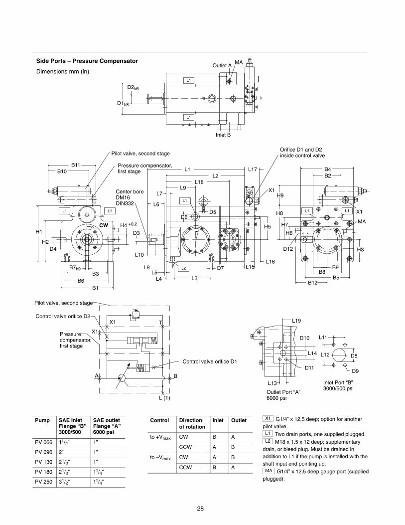
Side Ports – Pressure Compensator
Dimensions mm (in)
Control valve orifice D1
L (T)
BA
TControl valve orifice D2
Pilot valve, second stage
Pressure compensator, first stage
X1
X1
Inlet Port “B” 3000/500 psi
Outlet Port “A” 6000 psi
L12
L11
D9
D8
L13
D11
D10
L14
L19
D1h8
D2k6
MA
L1
L1
H1
H2
H4 +0,2
D4
B6B3
B7h9
H8
H9
H3
B11B10
Orifice D1 and D2 inside control valve
B1
L1
L2
D3
Center bore DM16DIN332
L10
D6D5
D7
L3
L8L5
L4
L15L16
B
Outlet A
L6
L7L9
L18L2
L1 L17
H5 H7
H6
B12B5
B8B9
MA
B4B2
L1 L1
D12
Inlet B
L1
L1
Pressure compensator,first stage
Pilot valve, second stage
X1
X1
CW
Pump SAE InletFlange “B”3000/500
SAE outletFlange “A”6000 psi
PV 066 11/2” 1”
PV 090 2” 1”
PV 130 21/2” 1”
PV 180 21/2” 11/4”
PV 250 31/2” 11/4”
Control Directionof rotation
Inlet Outlet
to +Vmax CW B A
CCW A B
to –Vmax CW A B
CCW B A
X1 G1/4” x 12,5 deep; option for anotherpilot valve.L1 Two drain ports, one supplied plugged.L2 M18 x 1,5 x 12 deep; supplementary
drain, or bleed plug. Must be drained inaddition to L1 if the pump is installed with theshaft input end pointing up.MA G1/4” x 12,5 deep gauge port (supplied
plugged).
29
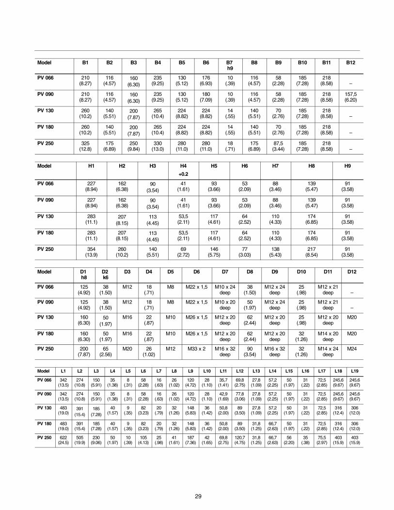
Model B1 B2 B3 B4 B5 B6 B7 h9
B8 B9 B10 B11 B12
PV 066 210(8.27)
116(4.57)
160(6.30)
235(9.25)
130(5.12)
176(6.93)
10(.39)
116(4.57)
58(2.28)
185(7.28)
218(8.58) –
PV 090 210(8.27)
116(4.57)
160(6.30)
235(9.25)
130(5.12)
180(7.09)
10(.39)
116(4.57)
58(2.28)
185(7.28)
218(8.58)
157,5(6.20)
PV 130 260(10.2)
140(5.51)
200(7.87)
265(10.4)
224(8.82)
224(8.82)
14(.55)
140(5.51)
70(2.76)
185(7.28)
218(8.58) –
PV 180 260(10.2)
140(5.51)
200(7.87)
265(10.4)
224(8.82)
224(8.82)
14(.55)
140(5.51)
70(2.76)
185(7.28)
218(8.58) –
PV 250 325(12.8)
175(6.89)
250(9.84)
330(13.0)
280(11.0)
280(11.0)
18(.71)
175(6.89)
87,5(3.44)
185(7.28)
218(8.58) –
Model H1 H2 H3 H4
+0.2
H5 H6 H7 H8 H9
PV 066 227(8.94)
162(6.38)
90(3.54)
41(1.61)
93(3.66)
53(2.09)
88(3.46)
139(5.47)
91(3.58)
PV 090 227(8.94)
162(6.38)
90(3.54)
41(1.61)
93(3.66)
53(2.09)
88(3.46)
139(5.47)
91(3.58)
PV 130 283(11.1)
207(8.15)
113(4.45)
53,5(2.11)
117(4.61)
64(2.52)
110(4.33)
174(6.85)
91(3.58)
PV 180 283(11.1)
207(8.15)
113(4.45)
53,5(2.11)
117(4.61)
64(2.52)
110(4.33)
174(6.85)
91(3.58)
PV 250 354(13.9)
260(10.2)
140(5.51)
69(2.72)
146(5.75)
77(3.03)
138(5.43)
217(8.54)
91(3.58)
Model D1 h8
D2 k6
D3 D4 D5 D6 D7 D8 D9 D10 D11 D12
PV 066 125(4.92)
38(1.50)
M12 18(.71)
M8 M22 x 1,5 M10 x 24deep
38(1.50)
M12 x 24deep
25(.98)
M12 x 21deep –
PV 090 125(4.92)
38(1.50)
M12 18(.71)
M8 M22 x 1,5 M10 x 20deep
50(1.97)
M12 x 24deep
25(.98)
M12 x 21deep –
PV 130 160(6.30)
50(1.97)
M16 22(.87)
M10 M26 x 1,5 M12 x 20deep
62(2.44)
M12 x 20deep
25(.98)
M12 x 20deep
M20
PV 180 160(6.30)
50(1.97)
M16 22(.87)
M10 M26 x 1,5 M12 x 20deep
62(2.44)
M12 x 20deep
32(1.26)
M14 x 20deep
M20
PV 250 200(7.87)
65(2.56)
M20 26(1.02)
M12 M33 x 2 M16 x 32deep
90(3.54)
M16 x 32deep
32(1.26)
M14 x 24deep
M24
Model L1 L2 L3 L4 L5 L6 L7 L8 L9 L10 L11 L12 L13 L14 L15 L16 L17 L18 L19
PV 066 342(13.5)
274(10.8)
150(5.91)
35(1.38)
8(.31)
58(2.28)
16(.63)
26(1.02)
120(4.72)
28(1.10)
35,7(1.41)
69,8(2.75)
27,8(1.09)
57,2(2.25)
50(1.97)
31(.22)
72,5(2.85)
245,6(9.67)
245,6(9.67)
PV 090 342(13.5)
274(10.8)
150(5.91)
35(1.38)
8(.31)
58(2.28)
16(.63)
26(1.02)
120(4.72)
28(1.10)
42,9(1.69)
77,8(3.06)
27,8(1.09)
57,2(2.25)
50(1.97)
31(.22)
72,5(2.85)
245,6(9.67)
245,6(9.67)
PV 130 483(19.0)
391(15.4)
185(7.28)
40(1.57)
9(.35)
82(3.23)
20(.79)
32(1.26)
148(5.83)
36(1.42)
50,8(2.00)
89(3.50)
27,8(1.09)
57,2(2.25)
50(1.97)
31(.22)
72,5(2.85)
316(12.4)
306(12.0)
PV 180 483(19.0)
391(15.4)
185(7.28)
40(1.57)
9(.35)
82(3.23)
20(.79)
32(1.26)
148(5.83)
36(1.42)
50,8(2.00)
89(3.50)
31,8(1.25)
66,7(2.63)
50(1.97)
31(.22)
72,5(2.85)
316(12.4)
306(12.0)
PV 250 622(24.5)
505(19.9)
230(9.06)
50(1.97)
10(.39)
105(4.13)
25(.98)
41(1.61)
187(7.36)
42(1.65)
69,8(2.75)
120,7(4.75)
31,8(1.25)
66,7(2.63)
56(2.20)
35(.38)
75,5(2.97)
403(15.9)
403(15.9)
30
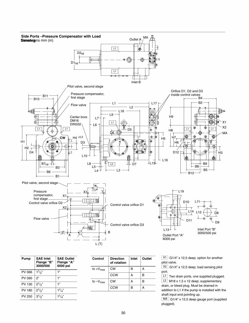
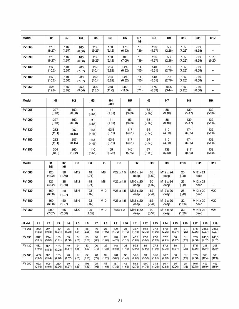
Side Ports –Pressure Compensator with LoadSensingDimensions mm (in)
Inlet Port “B” 3000/500 psi
Outlet Port “A” 6000 psi
L12
L11
D9
D8
L13
D11
D10
L14
L19
D1h8
D2k6
MA
L1
L1
H1
H2
H4 +0,2
D4
B6B3
B7h9
H8
H9
H3
B11B10
Orifice D1, D2 and D3inside control valves
B1
L1
L2
D3
Center bore DM16DIN332
L10
D6D5
D7
L3
L8L5
L4
L15L16
B
Outlet A
L6
L7L9
L18L2
L1 L17
H5 H7
H6
B12B5
B8B9
MA
B4B2
L1 L1
D12
Inlet B
L1
L1
Pressure compensator,first stage
Pilot valve, second stage
X1
Control valve orifice D1
L (T)
BA
T
Pilot valve, second stage
Pressure compensator, first stage
X1
X2
Control valve orifice D3
Flow valve
Control valve orifice D2
X1
Flow valve
X2
CW
Pump SAE InletFlange “B”3000/500
SAE OutletFlange “A”6000 psi
PV 066 11/2” 1”
PV 090 2” 1”
PV 130 21/2” 1”
PV 180 21/2” 11/4”
PV 250 31/2” 11/4”
Control Directionof rotation
Inlet Outlet
to +Vmax CW B A
CCW A B
to –Vmax CW A B
CCW B A
X1 G1/4” x 12,5 deep; option for anotherpilot valve.X2 G1/4” x 12,5 deep; load sensing pilot
port.L1 Two drain ports, one supplied plugged.L2 M18 x 1,5 x 12 deep; supplementary
drain, or bleed plug. Must be drained inaddition to L1 if the pump is installed with theshaft input end pointing up.MA G1/4” x 12,5 deep gauge port (supplied
plugged).
31
Model B1 B2 B3 B4 B5 B6 B7 h9
B8 B9 B10 B11 B12
PV 066 210(8.27)
116(4.57)
160(6.30)
235(9.25)
130(5.12)
176(6.93)
10(.39)
116(4.57)
58(2.28)
185(7.28)
218(8.58) –
PV 090 210(8.27)
116(4.57)
160(6.30)
235(9.25)
130(5.12)
180(7.09)
10(.39)
116(4.57)
58(2.28)
185(7.28)
218(8.58)
157,5(6.20)
PV 130 260(10.2)
140(5.51)
200(7.87)
265(10.4)
224(8.82)
224(8.82)
14(.55)
140(5.51)
70(2.76)
185(7.28)
218(8.58) –
PV 180 260(10.2)
140(5.51)
200(7.87)
265(10.4)
224(8.82)
224(8.82)
14(.55)
140(5.51)
70(2.76)
185(7.28)
218(8.58) –
PV 250 325(12.8)
175(6.89)
250(9.84)
330(13.0)
280(11.0)
280(11.0)
18(.71)
175(6.89)
87,5(3.44)
185(7.28)
218(8.58) –
Model H1 H2 H3 H4 +0.2
H5 H6 H7 H8 H9
PV 066 227(8.94)
162(6.38)
90(3.54)
41(1.61)
93(3.66)
53(2.09)
88(3.46)
139(5.47)
132(5.20)
PV 090 227(8.94)
162(6.38)
90(3.54)
41(1.61)
93(3.66)
53(2.09)
88(3.46)
139(5.47)
132(5.20)
PV 130 283(11.1)
207(8.15)
113(4.45)
53,5(2.11)
117(4.61)
64(2.52)
110(4.33)
174(6.85)
132(5.20)
PV 180 283(11.1)
207(8.15)
113(4.45)
53,5(2.11)
117(4.61)
64(2.52)
110(4.33)
174(6.85)
132(5.20)
PV 250 354(13.9)
260(10.2)
140(5.51)
69(2.72)
146(5.75)
77(3.03)
138(5.43)
217(8.54)
132(5.20)
Model D1 h8
D2 k6
D3 D4 D5 D6 D7 D8 D9 D10 D11 D12
PV 066 125(4.92)
38(1.50)
M12 18(.71)
M8 M22 x 1,5 M10 x 24deep
38(1.50)
M12 x 24deep
25(.98)
M12 x 21deep –
PV 090 125(4.92)
38(1.50)
M12 18(.71)
M8 M22 x 1,5 M10 x 20deep
50(1.97)
M12 x 24deep
25(.98)
M12 x 21deep –
PV 130 160(6.30)
50(1.97)
M16 22(.87)
M10 M26 x 1,5 M12 x 20deep
62(2.44)
M12 x 20deep
25(.98)
M12 x 20deep
M20
PV 180 160(6.30)
50(1.97)
M16 22(.87)
M10 M26 x 1,5 M12 x 20deep
62(2.44)
M12 x 20deep
32(1.26)
M14 x 20deep
M20
PV 250 200(7.87)
65(2.56)
M20 26(1.02)
M12 M33 x 2 M16 x 32deep
90(3.54)
M16 x 32deep
32(1.26)
M14 x 24deep
M24
Model L1 L2 L3 L4 L5 L6 L7 L8 L9 L10 L11 L12 L13 L14 L15 L16 L17 L18 L19
PV 066 342(13.5)
274(10.8)
150(5.91)
35(1.38)
8(.31)
58(2.28)
16(.63)
26(1.02)
120(4.72)
28(1.10)
35,7(1.41)
69,8(2.75)
27,8(1.09)
57,2(2.25)
50(1.97)
31(.22)
67,5(2.66)
245,6(9.67)
245,6(9.67)
PV 090 342(13.5)
274(10.8)
150(5.91)
35(1.38)
8(.31)
58(2.28)
16(.63)
26(1.02)
120(4.72)
28(1.10)
42,9(1.69)
77,8(3.06)
27,8(1.09)
57,2(2.25)
50(1.97)
31(.22)
67,5(2.66)
245,6(9.67)
245,6(9.67)
PV 130 483(19.0)
391(15.4)
185(7.28)
40(1.57)
9(.35)
82(3.23)
20(.79)
32(1.26)
148(5.83)
36(1.42)
50,8(2.00)
89(3.50)
27,8(1.09)
57,2(2.25)
50(1.97)
31(.22)
67,5(2.66)
316(12.4)
306(12.0)
PV 180 483(19.0)
391(15.4)
185(7.28)
40(1.57)
9(.35)
82(3.23)
20(.79)
32(1.26)
148(5.83)
36(1.42)
50,8(2.00)
89(3.50)
31,8(1.25)
66,7(2.63)
50(1.97)
31(.22)
67,5(2.66)
316(12.4)
306(12.0)
PV 250 622(24.5)
505(19.9)
230(9.06)
50(1.97)
10(.39)
105(4.13)
25(.98)
41(1.61)
187(7.36)
42(1.65)
69,8(2.75)
120,7(4.75)
31,8(1.25)
66,7(2.63)
56(2.20)
35(.38)
70,5(2.78)
403(15.9)
403(15.9)
32
Dimensions mm (in)
Inlet Port “B” 3000/500 psi
Outlet Port “A” 6000 psi
L12
L11
D9
D8
L13
D11
D10
L14
L19
D1h8
D2k6
MA
L1
L1
H1
H2
H4 +0,2
D4
B6B3
B7h9
H8
H9
H3
B11B10
Orifice D1 and D2 inside control valve
B1
L1
L2
D3
Center bore DM16DIN332
L10
D6D5
D7
L3
L8L5
L4
L15L16
B
Outlet A
L6
L7L9
L18L2
L1 L17
H5 H7
H6
B12B5
B8B9
MA
B4B2
L1
D12
Inlet B
L1
L1
Pressure compensator,first stage
Pilot valve, second stage
X1
X1
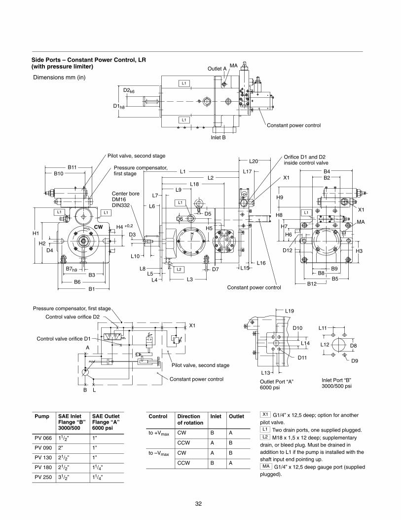
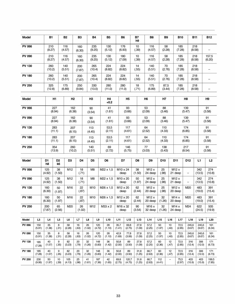
Side Ports – Constant Power Control, LR(with pressure limiter)
LB
A
Control valve orifice D1
Pilot valve, second stage
Pressure compensator, first stage
X1
Constant power control
Control valve orifice D2
L20
Constant power control
Constant power control
CW
Pump SAE InletFlange “B”3000/500
SAE OutletFlange “A”6000 psi
PV 066 11/2” 1”
PV 090 2” 1”
PV 130 21/2” 1”
PV 180 21/2” 11/4”
PV 250 31/2” 11/4”
Control Directionof rotation
Inlet Outlet
to +Vmax CW B A
CCW A B
to –Vmax CW A B
CCW B A
X1 G1/4” x 12,5 deep; option for anotherpilot valve.L1 Two drain ports, one supplied plugged.L2 M18 x 1,5 x 12 deep; supplementary
drain, or bleed plug. Must be drained inaddition to L1 if the pump is installed with theshaft input end pointing up.MA G1/4” x 12,5 deep gauge port (supplied
plugged).
33
Model B1 B2 B3 B4 B5 B6 B7 h9
B8 B9 B10 B11 B12
PV 066 210(8.27)
116(4.57)
160(6.30)
235(9.25)
130(5.12)
176(6.93)
10(.39)
116(4.57)
58(2.28)
185(7.28)
218(8.58) –
PV 090 210(8.27)
116(4.57)
160(6.30)
235(9.25)
130(5.12)
180(7.09)
10(.39)
116(4.57)
58(2.28)
185(7.28)
218(8.58)
157,5(6.20)
PV 130 260(10.2)
140(5.51)
200(7.87)
265(10.4)
224(8.82)
224(8.82)
14(.55)
140(5.51)
70(2.76)
185(7.28)
218(8.58) –
PV 180 260(10.2)
140(5.51)
200(7.87)
265(10.4)
224(8.82)
224(8.82)
14(.55)
140(5.51)
70(2.76)
185(7.28)
218(8.58) –
PV 250 325(12.8)
175(6.89)
250(9.84)
330(13.0)
280(11.0)
280(11.0)
18(.71)
175(6.89)
87,5(3.44)
185(7.28)
218(8.58) –
Model H1 H2 H3 H4 +0.2
H5 H6 H7 H8 H9
PV 066 227(8.94)
162(6.38)
90(3.54)
41(1.61)
93(3.66)
53(2.09)
88(3.46)
139(5.47)
91(3.58)
PV 090 227(8.94)
162(6.38)
90(3.54)
41(1.61)
93(3.66)
53(2.09)
88(3.46)
139(5.47)
91(3.58)
PV 130 283(11.1)
207(8.15)
113(4.45)
53,5(2.11)
117(4.61)
64(2.52)
110(4.33)
174(6.85)
91(3.58)
PV 180 283(11.1)
207(8.15)
113(4.45)
53,5(2.11)
117(4.61)
64(2.52)
110(4.33)
174(6.85)
91(3.58)
PV 250 354(13.9)
260(10.2)
140(5.51)
69(2.72)
146(5.75)
77(3.03)
138(5.43)
217(8.54)
91(3.58)
Model D1 h8
D2 k6
D3 D4 D5 D6 D7 D8 D9 D10 D11 D12 L1 L2
PV 066 125(4.92)
38(1.50)
M12 18(.71)
M8 M22 x 1,5 M10 x 24deep
38(1.50)
M12 x24 deep
25(.98)
M12 x21 deep –
342(13.5)
274(10.8)
PV 090 125(4.92)
38(1.50)
M12 18(.71)
M8 M22 x 1,5 M10 x 20deep
50(1.97)
M12 x24 deep
25(.98)
M12 x21 deep –
342(13.5)
274(10.8)
PV 130 160(6.30)
50(1.97)
M16 22(.87)
M10 M26 x 1,5 M12 x 20deep
62(2.44)
M12 x20 deep
25(.98)
M12 x20 deep
M20 483(19.0)
391(15.4)
PV 180 160(6.30)
50(1.97)
M16 22(.87)
M10 M26 x 1,5 M12 x 20deep
62(2.44)
M12 x20 deep
32(1.26)
M14 x20 deep
M20 483(19.0)
391(15.4)
PV 250 200(7.87)
65(2.56)
M20 26(1.02)
M12 M33 x 2 M16 x 32deep
90(3.54)
M16 x32 deep
32(1.26)
M14 x24 deep
M24 622(24.5)
505(19.9)
Model L3 L4 L5 L6 L7 L8 L9 L10 L11 L12 L13 L14 L15 L16 L17 L18 L19 L20
PV 066 150(5.91)
35(1.38)
8(.31)
58(2.28)
16(.63)
26(1.02)
120(4.72)
28(1.10)
35,7(1.41)
69,8(2.75)
27,8(1.09)
57,2(2.25)
50(1.97)
10(.40)
72,5(2.85)
245,6(9.67)
245,6(9.67)
161(6.34)
PV 090 150(5.91)
35(1.38)
8(.31)
58(2.28)
16(.63)
26(1.02)
120(4.72)
28(1.10)
42,9(1.69)
77,8(3.06)
27,8(1.09)
57,2(2.25)
50(1.97)
10(.40)
72,5(2.85)
245,6(9.67)
245,6(9.67)
161(6.34)
PV 130 185(7.28)
40(1.57)
9(.35)
82(3.23)
20(.79)
32(1.26)
148(5.83)
36(1.42)
50,8(2.00)
89(3.50)
27,8(1.09)
57,2(2.25)
60(2.36)
12(.47)
72,5(2.85)
316(12.4)
306(12.0)
171(6.73)
PV 180 185(7.28)
40(1.57)
9(.35)
82(3.23)
20(.79)
32(1.26)
148(5.83)
36(1.42)
50,8(2.00)
89(3.50)
31,8(1.25)
66,7(2.63)
60(2.36)
12(.47)
72,5(2.85)
316(12.4)
306(12.0)
171(6.73)
PV 250 230(9.06)
50(1.97)
10(.39)
105(4.13)
25(.98)
41(1.61)
187(7.36)
42(1.65)
69,8(2.75)
120,7(4.75)
31,8(1.25)
66,7(2.63)
112(4.41)
– 75,5(2.97)
403(15.9)
403(15.9)
199,5(7.85)
34
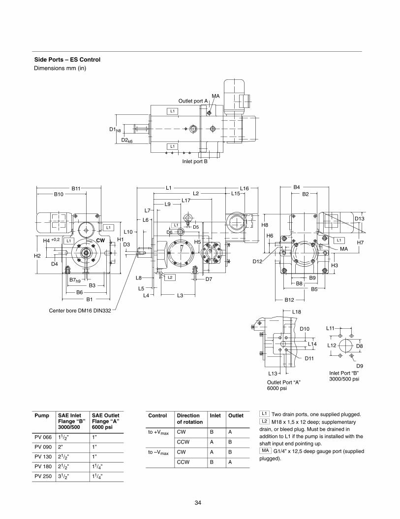
Side Ports – ES ControlDimensions mm (in)
D1h8
D2k6
MA
H1
H2
H4 +0,2
D4
B6B3
B7h9
Center bore DM16 DIN332
H3
MA
B11B10
L2
L1
B1
Outlet Port “A” 6000 psi
L12
L11
D9
D8
L13
D11
D10
L14
L18
Inlet Port “B” 3000/500 psi
Outlet port A
Inlet port B
L1
L1 L16L15L2
L17L9
L7
L6
D3
L10
L8
L5L4 L3
D7
D6
H5
D5
L1
L1
D12
B12
B5B8
B9
H8
H6
B4B2
D13
H7L1
L1
B
CW
Pump SAE InletFlange “B”3000/500
SAE OutletFlange “A”6000 psi
PV 066 11/2” 1”
PV 090 2” 1”
PV 130 21/2” 1”
PV 180 21/2” 11/4”
PV 250 31/2” 11/4”
Control Directionof rotation
Inlet Outlet
to +Vmax CW B A
CCW A B
to –Vmax CW A B
CCW B A
L1 Two drain ports, one supplied plugged.L2 M18 x 1,5 x 12 deep; supplementary
drain, or bleed plug. Must be drained inaddition to L1 if the pump is installed with theshaft input end pointing up.MA G1/4” x 12,5 deep gauge port (supplied
plugged).
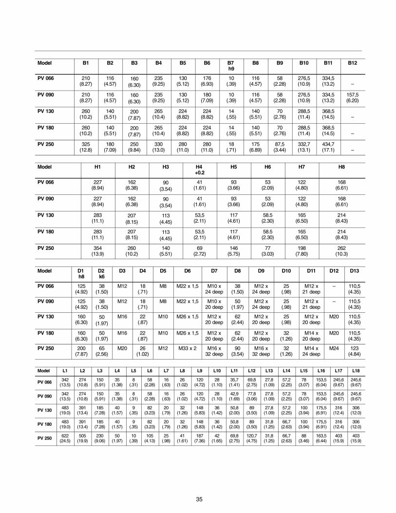
35
Model B1 B2 B3 B4 B5 B6 B7 h9
B8 B9 B10 B11 B12
PV 066 210(8.27)
116(4.57)
160(6.30)
235(9.25)
130(5.12)
176(6.93)
10(.39)
116(4.57)
58(2.28)
276,5(10.9)
334,5(13.2) –
PV 090 210(8.27)
116(4.57)
160(6.30)
235(9.25)
130(5.12)
180(7.09)
10(.39)
116(4.57)
58(2.28)
276,5(10.9)
334,5(13.2)
157,5(6.20)
PV 130 260(10.2)
140(5.51)
200(7.87)
265(10.4)
224(8.82)
224(8.82)
14(.55)
140(5.51)
70(2.76)
288,5(11.4)
368,5(14.5) –
PV 180 260(10.2)
140(5.51)
200(7.87)
265(10.4)
224(8.82)
224(8.82)
14(.55)
140(5.51)
70(2.76)
288,5(11.4)
368,5(14.5) –
PV 250 325(12.8)
180(7.09)
250(9.84)
330(13.0)
280(11.0)
280(11.0)
18(.71)
175(6.89)
87,5(3.44)
332,7(13.1)
434,7(17.1) –
Model H1 H2 H3 H4 +0.2
H5 H6 H7 H8
PV 066 227(8.94)
162(6.38)
90(3.54)
41(1.61)
93(3.66)
53(2.09)
122(4.80)
168(6.61)
PV 090 227(8.94)
162(6.38)
90(3.54)
41(1.61)
93(3.66)
53(2.09)
122(4.80)
168(6.61)
PV 130 283(11.1)
207(8.15)
113(4.45)
53,5(2.11)
117(4.61)
58.5(2.30)
165(6.50)
214(8.43)
PV 180 283(11.1)
207(8.15)
113(4.45)
53,5(2.11)
117(4.61)
58.5(2.30)
165(6.50)
214(8.43)
PV 250 354(13.9)
260(10.2)
140(5.51)
69(2.72)
146(5.75)
77(3.03)
198(7.80)
262(10.3)
Model D1 h8
D2 k6
D3 D4 D5 D6 D7 D8 D9 D10 D11 D12 D13
PV 066 125(4.92)
38(1.50)
M12 18(.71)
M8 M22 x 1,5 M10 x24 deep
38(1.50)
M12 x24 deep
25(.98)
M12 x21 deep
– 110,5(4.35)
PV 090 125(4.92)
38(1.50)
M12 18(.71)
M8 M22 x 1,5 M10 x20 deep
50(1.97)
M12 x24 deep
25(.98)
M12 x21 deep
– 110,5(4.35)
PV 130 160(6.30)
50(1.97)
M16 22(.87)
M10 M26 x 1,5 M12 x20 deep
62(2.44)
M12 x20 deep
25(.98)
M12 x20 deep
M20 110,5(4.35)
PV 180 160(6.30)
50(1.97)
M16 22(.87)
M10 M26 x 1,5 M12 x20 deep
62(2.44)
M12 x20 deep
32(1.26)
M14 x20 deep
M20 110,5(4.35)
PV 250 200(7.87)
65(2.56)
M20 26(1.02)
M12 M33 x 2 M16 x32 deep
90(3.54)
M16 x32 deep
32(1.26)
M14 x24 deep
M24 123(4.84)
Model L1 L2 L3 L4 L5 L6 L7 L8 L9 L10 L11 L12 L13 L14 L15 L16 L17 L18
PV 066 342(13.5)
274(10.8)
150(5.91)
35(1.38)
8(.31)
58(2.28)
16(.63)
26(1.02)
120(4.72)
28(1.10)
35,7(1.41)
69,8(2.75)
27,8(1.09)
57,2(2.25)
78(3.07)
153,5(6.04)
245,6(9.67)
245,6(9.67)
PV 090 342(13.5)
274(10.8)
150(5.91)
35(1.38)
8(.31)
58(2.28)
16(.63)
26(1.02)
120(4.72)
28(1.10)
42,9(1.69)
77,8(3.06)
27,8(1.09)
57,2(2.25)
78(3.07)
153,5(6.04)
245,6(9.67)
245,6(9.67)
PV 130 483(19.0)
391(13.4)
185(7.28)
40(1.57)
9(.35)
82(3.23)
20(.79)
32(1.26)
148(5.83)
36(1.42)
50,8(2.00)
89(3.50)
27,8(1.09)
57,2(2.25)
100(3.94)
175,5(6.91)
316(12.4)
306(12.0)
PV 180 483(19.0)
391(13.4)
185(7.28)
40(1.57)
9(.35)
82(3.23)
20(.79)
32(1.26)
148(5.83)
36(1.42)
50,8(2.00)
89(3.50)
31,8(1.25)
66,7(2.63)
100(3.94)
175,5(6.91)
316(12.4)
306(12.0)
PV 250 622(24.5)
505(19.9)
230(9.06)
50(1.97)
10(.39)
105(4.13)
25(.98)
41(1.61)
187(7.36)
42(1.65)
69,8(2.75)
120,7(4.75)
31,8(1.25)
66,7(2.63)
88(3.46)
163,5(6.44)
403(15.9)
403(15.9)
36
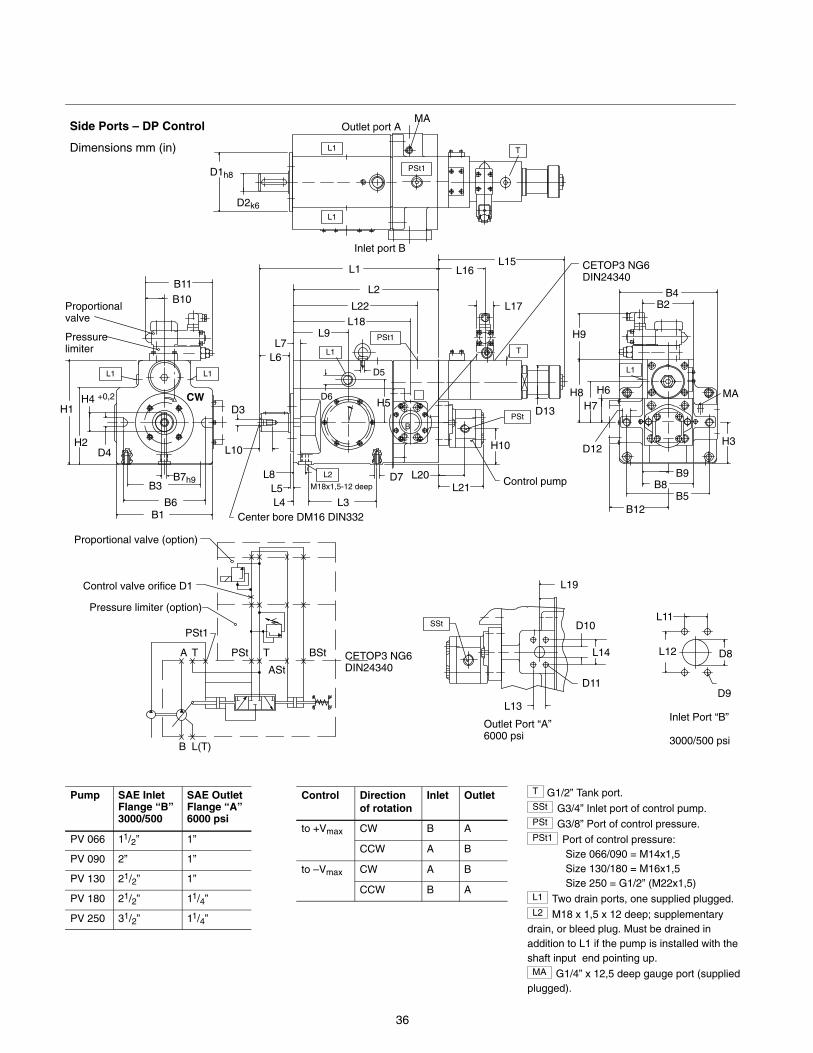
Side Ports – DP Control
Dimensions mm (in)
D1h8
D2k6
MA
H1
H2
H4 +0,2
D4
B6
B3B7h9
Center bore DM16 DIN332
H3
MA
B11B10
L2
PSt1
B1
Outlet Port “A” 6000 psi
L12
L11
D9
D8
L13
D11
D10
L14
Inlet Port “B”
3000/500 psi
L1
L10
L8L5L4 L3
D7
D6H5
D5L1
L1
D12
B12B5
B8B9
H8 H6
B4B2
D13 H7
L1
Outlet port A
Inlet port B
T
Proportional valve
Pressure limiter
L1
D3
M18x1,5-12 deep
PSt1
T
PSt
Control pump
L1L6L7
L9L18
L22
L2
L1L15
L16
L17
H10
L20L21
B
H9
CETOP3 NG6 DIN24340
Proportional valve (option)
Control valve orifice D1
Pressure limiter (option)
CETOP3 NG6 DIN24340
B L(T)
A T
PSt1
PSt T
ASt
BSt
SSt
L19
CW
Pump SAE InletFlange “B”3000/500
SAE OutletFlange “A”6000 psi
PV 066 11/2” 1”
PV 090 2” 1”
PV 130 21/2” 1”
PV 180 21/2” 11/4”
PV 250 31/2” 11/4”
Control Directionof rotation
Inlet Outlet
to +Vmax CW B A
CCW A B
to –Vmax CW A B
CCW B A
T G1/2” Tank port.SSt G3/4” Inlet port of control pump.PSt G3/8” Port of control pressure.PSt1 Port of control pressure:
Size 066/090 = M14x1,5 Size 130/180 = M16x1,5 Size 250 = G1/2” (M22x1,5)L1 Two drain ports, one supplied plugged.L2 M18 x 1,5 x 12 deep; supplementary
drain, or bleed plug. Must be drained inaddition to L1 if the pump is installed with theshaft input end pointing up.MA G1/4” x 12,5 deep gauge port (supplied
plugged).
37
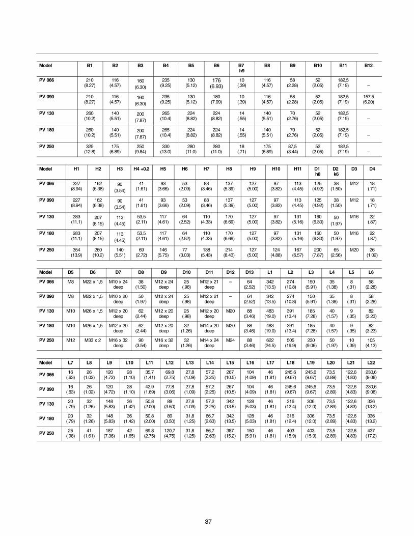
Model B1 B2 B3 B4 B5 B6 B7 h9
B8 B9 B10 B11 B12
PV 066 210(8.27)
116(4.57)
160(6.30)
235(9.25)
130(5.12)
176(6.93)
10(.39)
116(4.57)
58(2.28)
52(2.05)
182,5(7.19) –
PV 090 210(8.27)
116(4.57)
160(6.30)
235(9.25)
130(5.12)
180(7.09)
10(.39)
116(4.57)
58(2.28)
52(2.05)
182,5(7.19)
157,5(6.20)
PV 130 260(10.2)
140(5.51)
200(7.87)
265(10.4)
224(8.82)
224(8.82)
14(.55)
140(5.51)
70(2.76)
52(2.05)
182,5(7.19) –
PV 180 260(10.2)
140(5.51)
200(7.87)
265(10.4)
224(8.82)
224(8.82)
14(.55)
140(5.51)
70(2.76)
52(2.05)
182,5(7.19) –
PV 250 325(12.8)
175(6.89)
250(9.84)
330(13.0)
280(11.0)
280(11.0)
18(.71)
175(6.89)
87,5(3.44)
52(2.05)
182,5(7.19) –
Model H1 H2 H3 H4 +0.2 H5 H6 H7 H8 H9 H10 H11 D1 h8
D2 k6
D3 D4
PV 066 227(8.94)
162(6.38)
90(3.54)
41(1.61)
93(3.66)
53(2.09)
88(3.46)
137(5.39)
127(5.00)
97(3.82)
113(4.45)
125(4.92)
38(1.50)
M12 18(.71)
PV 090 227(8.94)
162(6.38)
90(3.54)
41(1.61)
93(3.66)
53(2.09)
88(3.46)
137(5.39)
127(5.00)
97(3.82)
113(4.45)
125(4.92)
38(1.50)
M12 18(.71)
PV 130 283(11.1)
207(8.15)
113(4.45)
53,5(2.11)
117(4.61)
64(2.52)
110(4.33)
170(6.69)
127(5.00)
97(3.82)
131(5.16)
160(6.30)
50(1.97)
M16 22(.87)
PV 180 283(11.1)
207(8.15)
113(4.45)
53,5(2.11)
117(4.61)
64(2.52)
110(4.33)
170(6.69)
127(5.00)
97(3.82)
131(5.16)
160(6.30)
50(1.97)
M16 22(.87)
PV 250 354(13.9)
260(10.2)
140(5.51)
69(2.72)
146(5.75)
77(3.03)
138(5.43)
214(8.43)
127(5.00)
124(4.88)
167(6.57)
200(7.87)
65(2.56)
M20 26(1.02)
Model D5 D6 D7 D8 D9 D10 D11 D12 D13 L1 L2 L3 L4 L5 L6
PV 066 M8 M22 x 1,5 M10 x 24deep
38(1.50)
M12 x 24deep
25(.98)
M12 x 21deep
– 64(2.52)
342(13.5)
274(10.8)
150(5.91)
35(1.38)
8(.31)
58(2.28)
PV 090 M8 M22 x 1,5 M10 x 20deep
50(1.97)
M12 x 24deep
25(.98)
M12 x 21deep
– 64(2.52)
342(13.5)
274(10.8)
150(5.91)
35(1.38)
8(.31)
58(2.28)
PV 130 M10 M26 x 1,5 M12 x 20deep
62(2.44)
M12 x 20deep
25(.98)
M12 x 20deep
M20 88(3.46)
483(19.0)
391(13.4)
185(7.28)
40(1.57)
9(.35)
82(3.23)
PV 180 M10 M26 x 1,5 M12 x 20deep
62(2.44)
M12 x 20deep
32(1.26)
M14 x 20deep
M20 88(3.46)
483(19.0)
391(13.4)
185(7.28)
40(1.57)
9(.35)
82(3.23)
PV 250 M12 M33 x 2 M16 x 32deep
90(3.54)
M16 x 32deep
32(1.26)
M14 x 24deep
M24 88(3.46)
622(24.5)
505(19.9)
230(9.06)
50(1.97)
10(.39)
105(4.13)
Model L7 L8 L9 L10 L11 L12 L13 L14 L15 L16 L17 L18 L19 L20 L21 L22
PV 066 16(.63)
26(1.02)
120(4.72)
28(1.10)
35,7(1.41)
69,8(2.75)
27,8(1.09)
57,2(2.25)
267(10.5)
104(4.09)
46(1.81)
245,6(9.67)
245,6(9.67)
73,5(2.89)
122,6(4.83)
230,6(9.08)
PV 090 16(.63)
26(1.02)
120(4.72)
28(1.10)
42,9(1.69)
77,8(3.06)
27,8(1.09)
57,2(2.25)
267(10.5)
104(4.09)
46(1.81)
245,6(9.67)
245,6(9.67)
73,5(2.89)
122,6(4.83)
230,6(9.08)
PV 130 20(.79)
32(1.26)
148(5.83)
36(1.42)
50,8(2.00)
89(3.50)
27,8(1.09)
57,2(2.25)
342(13.5)
128(5.03)
46(1.81)
316(12.4)
306(12.0)
73,5(2.89)
122,6(4.83)
336(13.2)
PV 180 20(.79)
32(1.26)
148(5.83)
36(1.42)
50,8(2.00)
89(3.50)
31,8(1.25)
66,7(2.63)
342(13.5)
128(5.03)
46(1.81)
316(12.4)
306(12.0)
73,5(2.89)
122,6(4.83)
336(13.2)
PV 250 25(.98)
41(1.61)
187(7.36)
42(1.65)
69,8(2.75)
120,7(4.75)
31,8(1.25)
66,7(2.63)
387(15.2)
150(5.91)
46(1.81)
403(15.9)
403(15.9)
73,5(2.89)
122,6(4.83)
437(17.2)
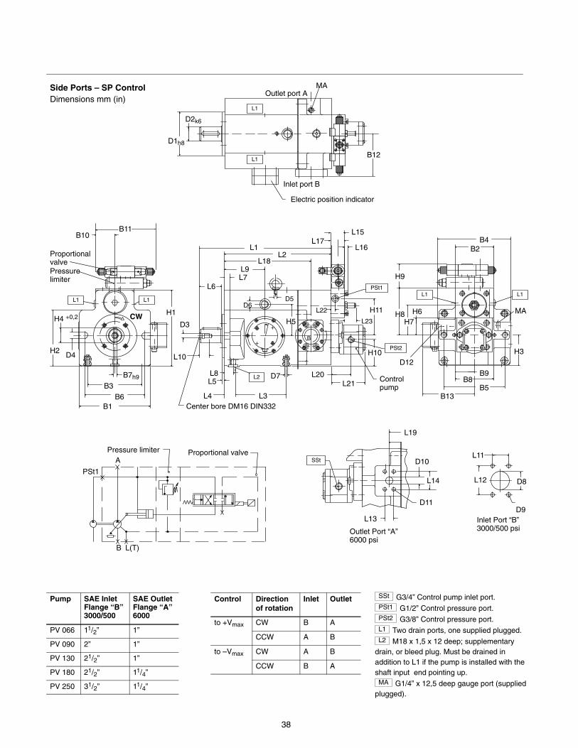
38
Side Ports – SP ControlDimensions mm (in)
D1h8
D2k6
MA
H1
H2
H4 +0,2
D4
B6
B3B7h9
Center bore DM16 DIN332
H3
MA
B11B10
L2
PSt2
B1
Outlet Port “A” 6000 psi
L12
L11
D9
D8
L13
D11
D10
L14
Inlet Port “B” 3000/500 psi
L1
L10
L8L5
L4 L3
D7
D6
H5
D5L1
L1
D12
B12
B5B8
B9
H8 H6
B4B2
H7
L1
Outlet port A
Inlet port B
Proportional valvePressure limiter
L1
D3
PSt1
Control pump
L1
L6L7L9
L18L2
L1
L15
L16L17
H10
L20L21
B
H9
Proportional valvePressure limiter
B L(T)
A
PSt1
SSt
L19
Electric position indicator
H11L23
L22
B13
CW
Pump SAE InletFlange “B”3000/500
SAE OutletFlange “A”6000
PV 066 11/2” 1”
PV 090 2” 1”
PV 130 21/2” 1”
PV 180 21/2” 11/4”
PV 250 31/2” 11/4”
Control Directionof rotation
Inlet Outlet
to +Vmax CW B A
CCW A B
to –Vmax CW A B
CCW B A
SSt G3/4” Control pump inlet port.PSt1 G1/2” Control pressure port.PSt2 G3/8” Control pressure port.L1 Two drain ports, one supplied plugged.L2 M18 x 1,5 x 12 deep; supplementary
drain, or bleed plug. Must be drained inaddition to L1 if the pump is installed with theshaft input end pointing up.MA G1/4” x 12,5 deep gauge port (supplied
plugged).
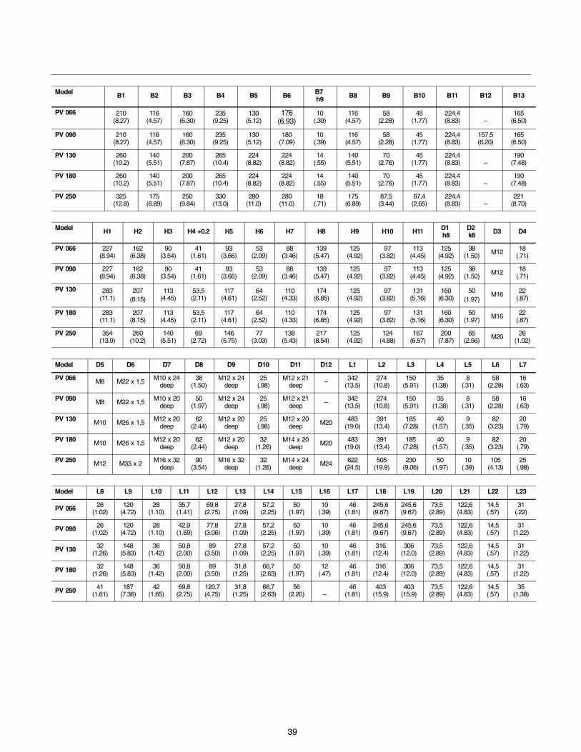
39
Model B1 B2 B3 B4 B5 B6 B7 h9 B8 B9 B10 B11 B12 B13
PV 066 210(8.27)
116(4.57)
160(6.30)
235(9.25)
130(5.12)
176(6.93)
10(.39)
116(4.57)
58(2.28)
45(1.77)
224,4(8.83) –
165(6.50)
PV 090 210(8.27)
116(4.57)
160(6.30)
235(9.25)
130(5.12)
180(7.09)
10(.39)
116(4.57)
58(2.28)
45(1.77)
224,4(8.83)
157,5(6.20)
165(6.50)
PV 130 260(10.2)
140(5.51)
200(7.87)
265(10.4)
224(8.82)
224(8.82)
14(.55)
140(5.51)
70(2.76)
45(1.77)
224,4(8.83) –
190(7.48)
PV 180 260(10.2)
140(5.51)
200(7.87)
265(10.4)
224(8.82)
224(8.82)
14(.55)
140(5.51)
70(2.76)
45(1.77)
224,4(8.83) –
190(7.48)
PV 250 325(12.8)
175(6.89)
250(9.84)
330(13.0)
280(11.0)
280(11.0)
18(.71)
175(6.89)
87,5(3.44)
67,4(2.65)
224,4(8.83) –
221(8.70)
Model H1 H2 H3 H4 +0.2 H5 H6 H7 H8 H9 H10 H11 D1 h8
D2 k6 D3 D4
PV 066 227(8.94)
162(6.38)
90(3.54)
41(1.61)
93(3.66)
53(2.09)
88(3.46)
139(5.47)
125(4.92)
97(3.82)
113(4.45)
125(4.92)
38(1.50) M12 18
(.71)
PV 090 227(8.94)
162(6.38)
90(3.54)
41(1.61)
93(3.66)
53(2.09)
88(3.46)
139(5.47)
125(4.92)
97(3.82)
113(4.45)
125(4.92)
38(1.50) M12 18
(.71)
PV 130 283(11.1)
207(8.15)
113(4.45)
53,5(2.11)
117(4.61)
64(2.52)
110(4.33)
174(6.85)
125(4.92)
97(3.82)
131(5.16)
160(6.30)
50(1.97)
M16 22(.87)
PV 180 283(11.1)
207(8.15)
113(4.45)
53,5(2.11)
117(4.61)
64(2.52)
110(4.33)
174(6.85)
125(4.92)
97(3.82)
131(5.16)
160(6.30)
50(1.97) M16 22
(.87)
PV 250 354(13.9)
260(10.2)
140(5.51)
69(2.72)
146(5.75)
77(3.03)
138(5.43)
217(8.54)
125(4.92)
124(4.88)
167(6.57)
200(7.87)
65(2.56) M20 26
(1.02)
Model D5 D6 D7 D8 D9 D10 D11 D12 L1 L2 L3 L4 L5 L6 L7
PV 066 M8 M22 x 1,5 M10 x 24deep
38(1.50)
M12 x 24deep
25(.98)
M12 x 21deep – 342
(13.5)274
(10.8)150
(5.91)35
(1.38)8
(.31)58
(2.28)16
(.63)
PV 090 M8 M22 x 1,5 M10 x 20deep
50(1.97)
M12 x 24deep
25(.98)
M12 x 21deep – 342
(13.5)274
(10.8)150
(5.91)35
(1.38)8
(.31)58
(2.28)16
(.63)
PV 130 M10 M26 x 1,5 M12 x 20deep
62(2.44)
M12 x 20deep
25(.98)
M12 x 20deep M20 483
(19.0)391
(13.4)185
(7.28)40
(1.57)9
(.35)82
(3.23)20
(.79)
PV 180 M10 M26 x 1,5 M12 x 20deep
62(2.44)
M12 x 20deep
32(1.26)
M14 x 20deep M20 483
(19.0)391
(13.4)185
(7.28)40
(1.57)9
(.35)82
(3.23)20
(.79)
PV 250 M12 M33 x 2 M16 x 32deep
90(3.54)
M16 x 32deep
32(1.26)
M14 x 24deep M24 622
(24.5)505
(19.9)230
(9.06)50
(1.97)10
(.39)105
(4.13)25
(.98)
Model L8 L9 L10 L11 L12 L13 L14 L15 L16 L17 L18 L19 L20 L21 L22 L23
PV 066 26(1.02)
120(4.72)
28(1.10)
35,7(1.41)
69,8(2.75)
27,8(1.09)
57,2(2.25)
50(1.97)
10(.39)
46(1.81)
245,6(9.67)
245,6(9.67)
73,5(2.89)
122,6(4.83)
14,5(.57)
31(.22)
PV 090 26(1.02)
120(4.72)
28(1.10)
42,9(1.69)
77,8(3.06)
27,8(1.09)
57,2(2.25)
50(1.97)
10(.39)
46(1.81)
245,6(9.67)
245,6(9.67)
73,5(2.89)
122,6(4.83)
14,5(.57)
31(1.22)
PV 130 32(1.26)
148(5.83)
36(1.42)
50,8(2.00)
89(3.50)
27,8(1.09)
57,2(2.25)
50(1.97)
10(.39)
46(1.81)
316(12.4)
306(12.0)
73,5(2.89)
122,6(4.83)
14,5(.57)
31(1.22)
PV 180 32(1.26)
148(5.83)
36(1.42)
50,8(2.00)
89(3.50)
31,8(1.25)
66,7(2.63)
50(1.97)
12(.47)
46(1.81)
316(12.4)
306(12.0)
73,5(2.89)
122,6(4.83)
14,5(.57)
31(1.22)
PV 250 41(1.61)
187(7.36)
42(1.65)
69,8(2.75)
120,7(4.75)
31,8(1.25)
66,7(2.63)
56(2.20) –
46(1.81)
403(15.9)
403(15.9)
73,5(2.89)
122,6(4.83)
14,5(.57)
35(1.38)
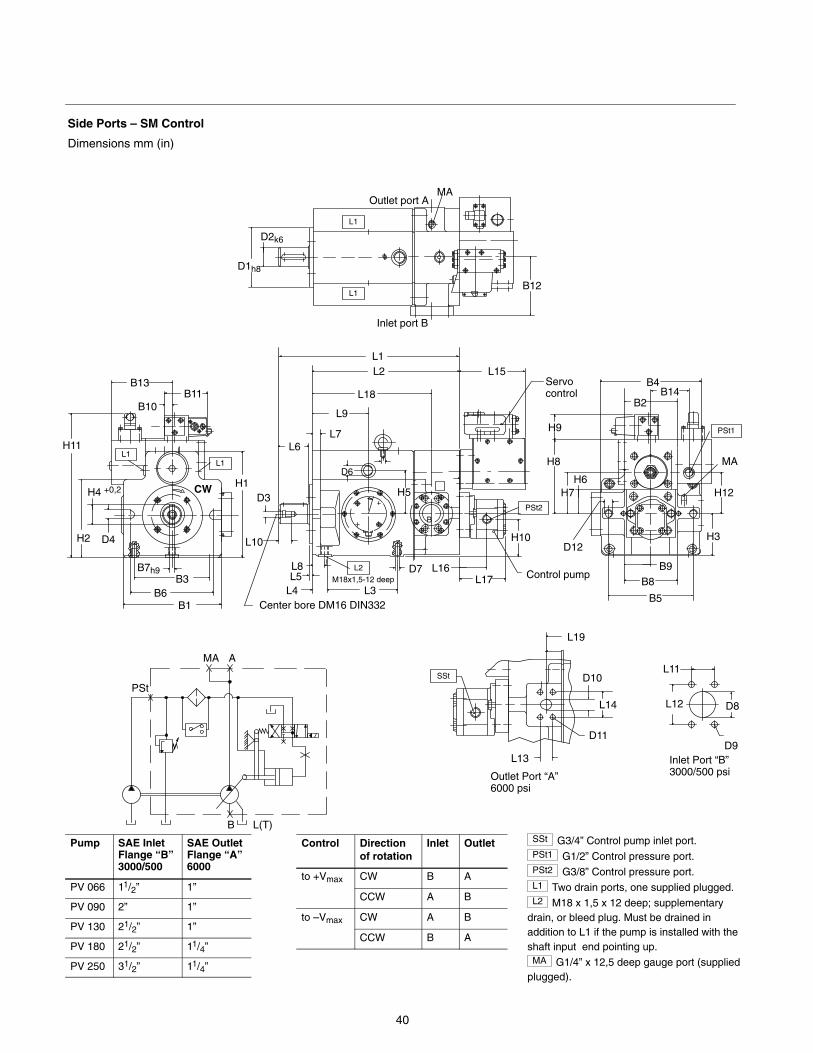
40
Side Ports – SM Control
Dimensions mm (in)
D1h8
D2k6
MA
H1
H2
H4 +0,2
D4
B6B3
B7h9
Center bore DM16 DIN332
H3
MA
B11B10
L2
PSt2
B1
Outlet Port “A” 6000 psi
L12
L11
D9
D8
L13
D11
D10
L14
Inlet Port “B” 3000/500 psi
L10
L8L5
L4 L3
D7
D6
H5
L1
L1
D12
B12
B5
B8
B9
H8
H6
B4
B2
H7
Outlet port A
Inlet port B
L1
D3
PSt1
Control pump
L1
L6L7
L9
L18
L2 L15
L16L17
H10
B
H9
B L(T)
A
PStSSt
L19
B13
MA
H11
M18x1,5-12 deep
Servo control B14
H12CW
L1
Pump SAE InletFlange “B”3000/500
SAE OutletFlange “A”6000
PV 066 11/2” 1”
PV 090 2” 1”
PV 130 21/2” 1”
PV 180 21/2” 11/4”
PV 250 31/2” 11/4”
Control Directionof rotation
Inlet Outlet
to +Vmax CW B A
CCW A B
to –Vmax CW A B
CCW B A
SSt G3/4” Control pump inlet port.PSt1 G1/2” Control pressure port.PSt2 G3/8” Control pressure port.L1 Two drain ports, one supplied plugged.L2 M18 x 1,5 x 12 deep; supplementary
drain, or bleed plug. Must be drained inaddition to L1 if the pump is installed with theshaft input end pointing up.MA G1/4” x 12,5 deep gauge port (supplied
plugged).
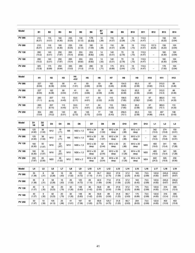
41
Model B1 B2 B3 B4 B5 B6 B7 h9 B8 B9 B10 B11 B12 B13 B14
PV 066 210(8.27)
116(4.57)
160(6.30)
235(9.25)
130(5.12)
176(6.93)
10(.39)
116(4.57)
58(2.28)
19(.75)
113,5(4.47) –
158(6.22)
100(3.94)
PV 090 210(8.27)
116(4.57)
160(6.30)
235(9.25)
130(5.12)
180(7.09)
10(.39)
116(4.57)
58(2.28)
19(.75)
113,5(4.47)
157,5(6.20)
158(6.22)
100(3.94)
PV 130 260(10.2)
140(5.51)
200(7.87)
265(10.4)
224(8.82)
224(8.82)
14(.55)
140(5.51)
70(2.76)
19(.75)
113,5(4.47) –
160(6.30)
100(3.94)
PV 180 260(10.2)
140(5.51)
200(7.87)
265(10.4)
224(8.82)
224(8.82)
14(.55)
140(5.51)
70(2.76)
19(.75)
113,5(4.47) –
160(6.30)
100(3.94)
PV 250 325(12.8)
175(6.89)
250(9.84)
330(13.0)
280(11.0)
280(11.0)
18(.71)
175(6.89)
87,5(3.44)
19(.75)
113,5(4.47) –
178(7.00)
100(3.94)
Model H1 H2 H3 H4 +0.2 H5 H6 H7 H8 H9 H10 H11 H12
PV 066 227(8.94)
162(6.38)
90(3.54)
41(1.61)
93(3.66)
53(2.09)
88(3.46)
154,5(6.08)
65,5(2.58)
97(3.82)
315,5(12.4)
88(3.46)
PV 090 227(8.94)
162(6.38)
90(3.54)
41(1.61)
93(3.66)
53(2.09)
88(3.46)
154,5(6.08)
65,5(2.58)
97(3.82)
315,5(12.4)
88(3.46)
PV 130 283(11.1)
207(8.15)
113(4.45)
53,5(2.11)
117(4.61)
64(2.52)
110(4.33)
199,5(7.85)
65,5(2.58)1
97(3.82)
383,5(15.1)
110(4.33)
PV 180 283(11.1)
207(8.15)
113(4.45)
53,5(2.11)
117(4.61)
64(2.52)
110(4.33)
199,5(7.85)
65,5(2.58)
97(3.82)
383,5(15.1)
110(4.33)
PV 250 354(13.9)
260(10.2)
140(5.51)
69(2.72)
146(5.75)
77(3.03)
138(5.43)
256,5(10.1)
65,5(2.58)
124(4.88)
467(18.4)
138(5.43)
Model D1 h8
D2 k6 D3 D4 D5 D6 D7 D8 D9 D10 D11 D12 L1 L2 L3
PV 066 125(4.92)
38(1.50) M12 18
(.71) M8 M22 x 1,5 M10 x 24deep
38(1.50)
M12 x 24deep
25(.98)
M12 x 21deep – 342
(13.5)274
(10.8)150
(5.91)
PV 090 125(4.92)
38(1.50) M12 18
(.71) M8 M22 x 1,5 M10 x 20deep
50(1.97)
M12 x 24deep
25(.98)
M12 x 21deep – 342
(13.5)274
(10.8)150
(5.91)
PV 130 160(6.30)
50(1.97)
M16 22(.87) M10 M26 x 1,5 M12 x 20
deep62
(2.44)M12 x 20
deep25
(.98)M12 x 20
deep M20 483(19.0)
341(13.4)
185(7.28)
PV 180 160(6.30)
50(1.97) M16 22
(.87) M10 M26 x 1,5 M12 x 20deep
62(2.44)
M12 x 20deep
32(1.26)
M14 x 20deep M20 483
(19.0)341
(13.4)185
(7.28)
PV 250 200(7.87)
65(2.56) M20 26
(1.02) M12 M33 x 2 M16 x 32deep
90(3.54)
M16 x 32deep
32(1.26)
M14 x 24deep M24 622
(24.5)505
(19.9)230
(9.06)
Model L4 L5 L6 L7 L8 L9 L10 L11 L12 L13 L14 L15 L16 L17 L18 L19
PV 066 35(1.38)
8(.31)
58(2.28)
16(.63)
26(1.02)
120(4.72)
28(1.10)
35,7(1.41)
69,8(2.75)
27,8(1.09)
57,2(2.25)
163(6.42)
73,5(2.89)
122,6(4.83)
245,6(9.67)
245,6(9.67)
PV 090 35(1.38)
8(.31)
58(2.28)
16(.63)
26(1.02)
120(4.72)
28(1.10)
42,9(1.69)
77,8(3.06)
27,8(1.09)
57,2(2.25)
163(6.42)
73,5(2.89)
122,6(4.83)
245,6(9.67)
245,6(9.67)
PV 130 40(1.57)
9(.35)
82(3.23)
20(.79)
32(1.26)
148(5.83)
36(1.42)
50,8(2.00)
89(3.50)
27,8(1.09)
57,2(2.25)
175(6.89)
73,5(2.89)
122,6(4.83)
316(12.4)
306(12.0)
PV 180 40(1.57)
9(.35)
82(3.23)
20(.79)
32(1.26)
148(5.83)
36(1.42)
50,8(2.00)
89(3.50)
31,8(1.25)
66,7(2.63)
175(6.89)
73,5(2.89)
122,6(4.83)
316(12.4)
306(12.0)
PV 250 50(1.97)
10(.39)
105(4.13)
25(.98)
41(1.61)
187(7.36)
42(1.65)
69,8(2.75)
120,7(4.75)
31,8(1.25)
66,7(2.63)
204(8.03)
73,5(2.89)
122,6(4.83)
403(15.9)
403(15.9)
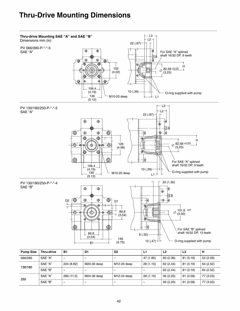
42
Thru-Drive Mounting Dimensions
Thru-drive Mounting SAE “A” and SAE “B”Dimensions mm (in)
PV 066/090-P-*-*-5 SAE “A”
PV 130/180/250-P-*-*-5 SAE “A”
PV 130/180/250-P-*-*-4 SAE “B”
106,4(4.19)130
(5.12)
102(4.02)
22 (.87)
L3L2
H82,58(3.25)∅
+0,03
For SAE “A” splined shaft 16/32 DP, 9 teeth
O-ring supplied with pumpL1
10 (.39)
126(4.96)
106,4(4.19)130
(5.12)M10-20 deep
M10-20 deep
O-ring supplied with pump
L3
L222 (.87)
H82,58(3.25)∅
+0,03
For SAE “A” splined shaft 16/32 DP, 9 teeth
B1146
(5.75)
89,8(3.54)
D2 D1
89,8(3.54)
33 (1.30)
101,6(4.00)∅
H7
For SAE “B” splined shaft 16/32 DP, 13 teeth
O-ring supplied with pump
10 (.39)
L1
9 (.35)
12 (.47)
Pump Size Thru-drive B1 D1 D2 L1 L2 L3 H
066/090 SAE “A” – – – 47 (1.85) 60 (2.36) 81 (3.19) 53 (2.09)
130/180SAE “A” 224 (8.82) M20-30 deep M12-20 deep 28 (1.10) 62 (2.44) 81 (3.19) 64 (2.52)
130/180SAE “B” – – – – 62 (2.44) 81 (3.19) 64 (2.52)
250SAE “A” 280 (11.0) M24-38 deep M12-24 deep 28 (1.10) 56 (2.20) 91 (3.58) 77 (3.03)
250SAE “B” – – – – 56 (2.20) 91 (3.58) 77 (3.03)
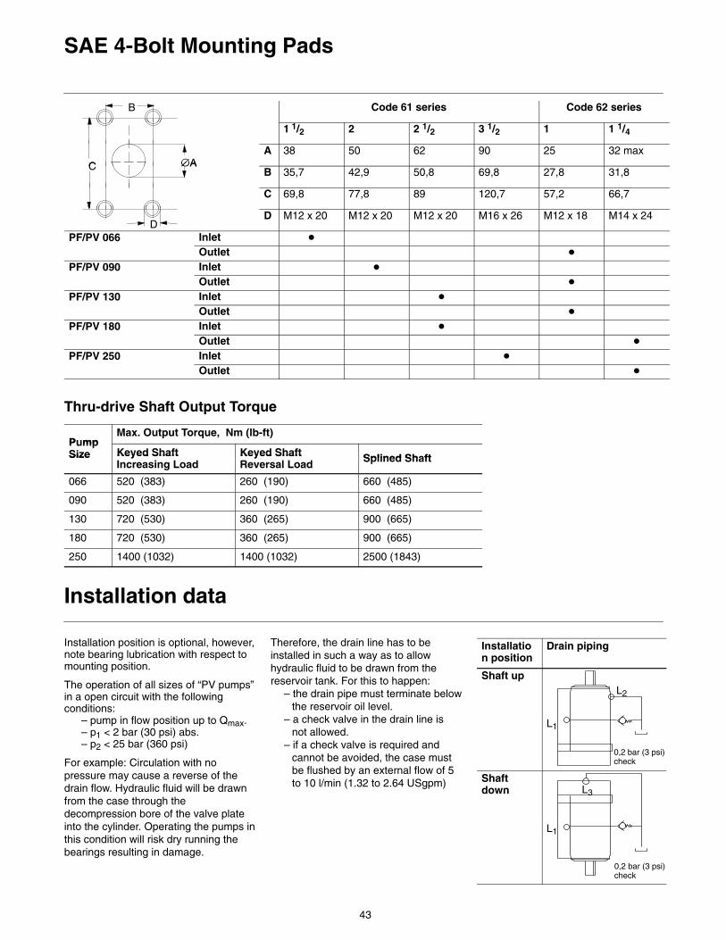
43
SAE 4-Bolt Mounting Pads
B Code 61 series Code 62 series
1 1/2 2 2 1/2 3 1/2 1 1 1/4
∅AC
A 38 50 62 90 25 32 max∅AC B 35,7 42,9 50,8 69,8 27,8 31,8
C 69,8 77,8 89 120,7 57,2 66,7
DD M12 x 20 M12 x 20 M12 x 20 M16 x 26 M12 x 18 M14 x 24
PF/PV 066 Inlet �
Outlet �
PF/PV 090 Inlet �
Outlet �
PF/PV 130 Inlet �
Outlet �
PF/PV 180 Inlet �
Outlet �
PF/PV 250 Inlet �
Outlet �
Thru-drive Shaft Output Torque
P mpMax. Output Torque, Nm (lb-ft)
PumpSize Keyed Shaft Keyed Shaft Splined Sh ftSize Keyed Shaft
Increasing LoadKeyed ShaftReversal Load Splined Shaft
066 520 (383) 260 (190) 660 (485)
090 520 (383) 260 (190) 660 (485)
130 720 (530) 360 (265) 900 (665)
180 720 (530) 360 (265) 900 (665)
250 1400 (1032) 1400 (1032) 2500 (1843)
Installation data
Installation position is optional, however,note bearing lubrication with respect tomounting position.
The operation of all sizes of “PV pumps”in a open circuit with the followingconditions:
– pump in flow position up to Qmax.– p1 < 2 bar (30 psi) abs.– p2 < 25 bar (360 psi)
For example: Circulation with nopressure may cause a reverse of thedrain flow. Hydraulic fluid will be drawnfrom the case through thedecompression bore of the valve plateinto the cylinder. Operating the pumps inthis condition will risk dry running thebearings resulting in damage.
Therefore, the drain line has to beinstalled in such a way as to allowhydraulic fluid to be drawn from thereservoir tank. For this to happen:
– the drain pipe must terminate below the reservoir oil level.
– a check valve in the drain line is not allowed.
– if a check valve is required and cannot be avoided, the case must be flushed by an external flow of 5 to 10 l/min (1.32 to 2.64 USgpm)
Installation position
Drain piping
Shaft up
L1
L2
0,2 bar (3 psi)check
Shaftdown
L1
L3
0,2 bar (3 psi)check
44
Application Data
Case flushing requirementsCase flushing is not necessary for openloop pumps with DR or LR controls.
A check valve must not be used in thedrain pipe. The drain pipe must terminatebelow the oil level in the reservoir.
Case flushing is not necessary for openloop pumps with DF controls if flushingor return oil is drained via the case.
For all other conditions with low pressure<20 bar (<300 psi) and low flow (<10% ofQmax) case flushing is required.
For operation with special fluids HFBand HFC, case flushing is required.
Flushing flowFlushing flow via the pump case should be>1% of maximum pump flow. Maximumflushing flow depends on case pressure.
FluidsPumps in this catalog are primarilydesigned to operate with conventionalpetroleum based hydraulic oil.Alternative fluids and restrictions:
NOTE:
1. All maximum speed figures are basedon atmospheric pressure (1.0 barabsolute) at pump inlet. This requiresan overhead reservoir.
2. All listed ratings are based on the useof a good quality fluid.
3. Alternative fluids have a reducedtolerance for contamination overpetroleum base fluids. Good filtrationis therefore critical.
Pressure and flow ratings of hydrauliccomponents generally have to be reducedwhen alternative fluids are used.
Because hydraulic pumps depend onthe pumping fluid for dynamiclubrication, it is necessary to alter theratings in order to retain the durabilityand operating life that is expected intoday’s hydraulic systems.
These pumps will provide exceptional lifewhen used with a good quality clean fluidat the pump ratings specified for that fluid.
Fluid maintenance is critical to thedurability of all hydraulic components,and particularly so woth hydraulicpumps. This becomes even more of afactor when alternative fluids are used.All types of alternative fluids requireextensive maintenance in order tomaintain proper levels of water content,acidity, viscosity and contamination.
Fluid CleanlinessThese pumps are rated for anti-wearpetroleum fluids with a contaminationlevel of 18/15/13 (Vickers) or ISO 18/14.Operation in fluids with levels morecontaminated than this is notrecommended. Fluids other thanpetroleum, severe service cycles, ortemperature extremes are cause foradjustment of these codes. Pleasecontact your Vickers representative forspecific duty cycle recommendations.
Vickers pumps, as with any variabledisplacement piston pumps, will operatewith apparent satisfaction in fluids up tothe rating specified here. Experiencehas shown, however, that pump andhydraulic system life is not optimizedwith high fluid contamination levels (highISO cleanliness codes).
Proper fluid condition is essential forlong and satisfactory life of hydrauliccomponents and systems. Hydraulicfluid must have the correct balance ofcleanliness, materials, and additives forprotection against wear of components,elevated viscosity, and inclusion of air.
Essential information on the correctmethods for treating hydraulic fluid isincluded in Vickers publication 561 –“Vickers Guide to SystemicContamination Control” – available fromyour local Vickers distributor. In thispublication, filtration and cleanlinesslevels for extending the life of axialpiston pumps and other systemcomponents are listed. Included is anexcellent discussion of the selection ofproducts needed to control fluid condition.
Ordering procedureWhen ordering please specify full modeldesignations of items required; see”Model codes” section of this catalog.
Note the following:– Designations of variable displacement
pumps must include thesupplementary designation of therequired control type.
FLUIDSType Classification
Max. Pressure bar
Max. Speed rpm
Recommended Seal Material
Max. OperatureTemperature �C
Oil-in-Water Emulsion HFAE Not Rated
Water-in-Oil Emulsion HFB 250 1800 Nitrile 49
Water Glycol HFC 250 1800 Nitrile 49
Phosphate Ester HFDR 350 / 420 1800 Fluorocarbon 66
Polyol Ester HFDU 350 / 420 1800 Fluorocarbon orHigh ACN Nitrile
66