Embed Size (px)
Citation preview
CONSTRUCTION DRAWINGS
FOR
SPRING OF BLESSING ASSEMBLY OF GOD
VICINITY MAP
SECTION 30, TOWNSHIP 27 S, RANGE 27 E
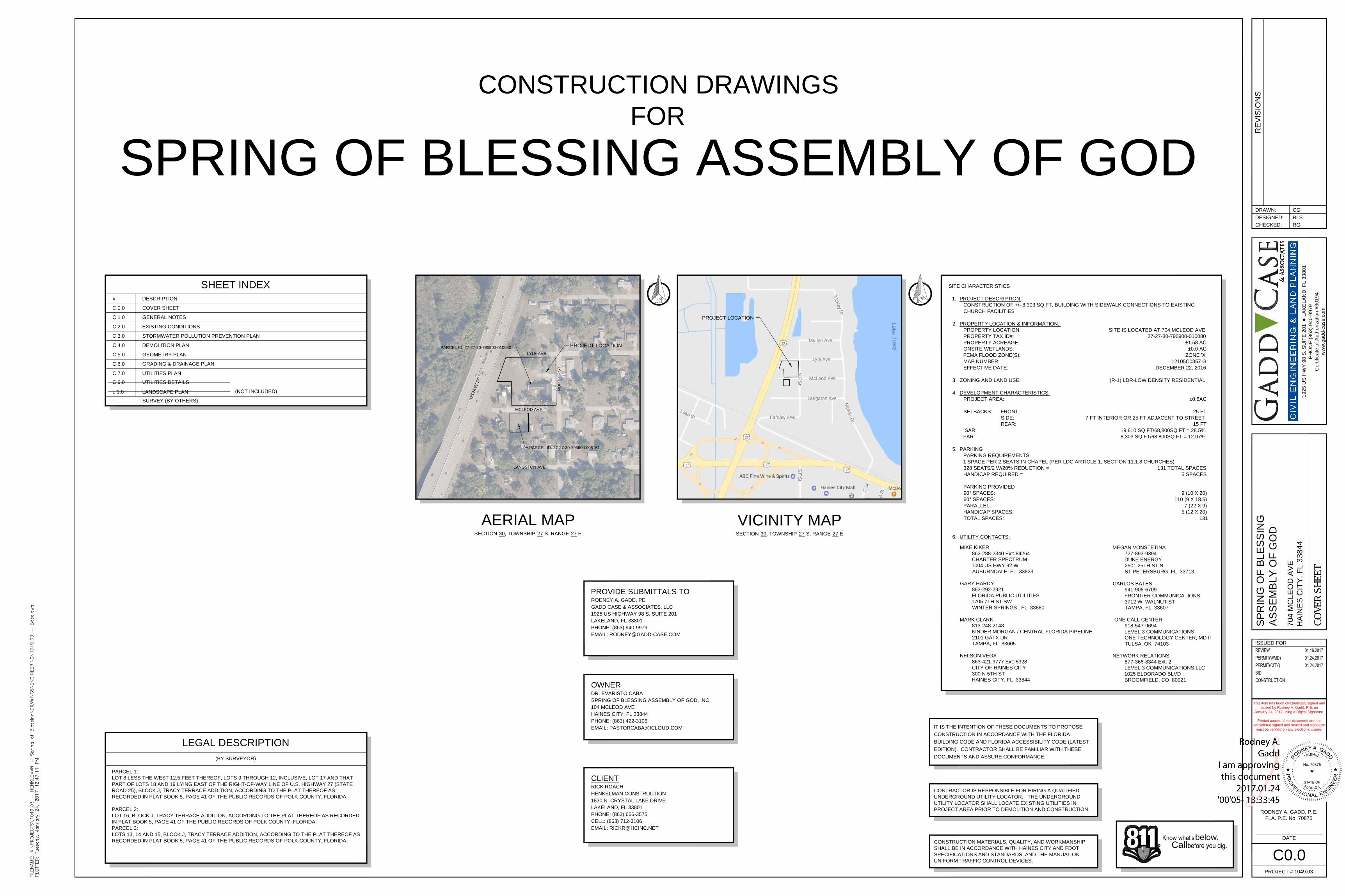
AERIAL MAP
SECTION 30, TOWNSHIP 27 S, RANGE 27 E
SHEET INDEX
LEGAL DESCRIPTION
OWNER
DR. EVARISTO CABA
SPRING OF BLESSING ASSEMBLY OF GOD, INC
104 MCLEOD AVE
HAINES CITY, FL 33844
PHONE: (863) 422-3106
EMAIL: [email protected]
CLIENT
RICK ROACH
HENKELMAN CONSTRUCTION
1830 N. CRYSTAL LAKE DRIVE
LAKELAND, FL 33801
PHONE: (863) 666-3575
CELL: (863) 712-3106
EMAIL: [email protected]
PROVIDE SUBMITTALS TO
RODNEY A. GADD, PE
GADD CASE & ASSOCIATES, LLC
1925 US HIGHWAY 98 S, SUITE 201
LAKELAND, FL 33801
PHONE: (863) 940-9979
EMAIL: [email protected]
below.
Call
R
SITE CHARACTERISTICS
1. PROJECT DESCRIPTION :
CONSTRUCTION OF +/- 8,303 SQ FT. BUILDING WITH SIDEWALK CONNECTIONS TO EXISTING
CHURCH FACILITIES
2. PROPERTY LOCATION & INFORMATION:
PROPERTY LOCATION: SITE IS LOCATED AT 704 MCLEOD AVE
PROPERTY TAX ID#: 27-27-30-790900-010080
PROPERTY ACREAGE: ±1.58 AC
ONSITE WETLANDS: ±0.0 AC
FEMA FLOOD ZONE(S): ZONE 'X'
MAP NUMBER: 12105C0357 G
EFFECTIVE DATE: DECEMBER 22, 2016
3. ZONING AND LAND USE: (R-1) LDR-LOW DENSITY RESIDENTIAL
4. DEVELOPMENT CHARACTERISTICS
PROJECT AREA: ±0.6AC
SETBACKS: FRONT: 25 FT
SIDE: 7 FT INTERIOR OR 25 FT ADJACENT TO STREET
REAR: 15 FT
ISAR: 19,610 SQ FT/68,800SQ FT = 28.5%
FAR: 8,303 SQ FT/68,800SQ FT = 12.07%
5. PARKING
PARKING REQUIREMENTS
1 SPACE PER 2 SEATS IN CHAPEL (PER LDC ARTICLE 1, SECTION 11.1.8 CHURCHES)
328 SEATS/2 W/20% REDUCTION = 131 TOTAL SPACES
HANDICAP REQUIRED = 5 SPACES
PARKING PROVIDED
90° SPACES: 9 (10 X 20)
60° SPACES: 110 (9 X 18.5)
PARALLEL: 7 (22 X 9)
HANDICAP SPACES: 5 (12 X 20)
TOTAL SPACES: 131
6. UTILITY CONTACTS:
MIKE KIKER
863-288-2340 Ext: 84264
CHARTER SPECTRUM
1004 US HWY 92 W
AUBURNDALE, FL 33823
GARY HARDY
863-292-2921
FLORIDA PUBLIC UTILITIES
1705 7TH ST SW
WINTER SPRINGS , FL 33880
MARK CLARK
813-248-2148
KINDER MORGAN / CENTRAL FLORIDA PIPELINE
2101 GATX DR
TAMPA, FL 33605
NELSON VEGA
863-421-3777 Ext: 5328
CITY OF HAINES CITY
300 N 5TH ST
HAINES CITY, FL 33844
MEGAN VONSTETINA
727-893-9394
DUKE ENERGY
2501 25TH ST N
ST PETERSBURG, FL 33713
CARLOS BATES
941-906-6709
FRONTIER COMMUNICATIONS
3712 W. WALNUT ST
TAMPA, FL 33607
ONE CALL CENTER
918-547-9694
LEVEL 3 COMMUNICATIONS
ONE TECHNOLOGY CENTER, MD II
TULSA, OK 74103
NETWORK RELATIONS
877-366-8344 Ext: 2
LEVEL 3 COMMUNICATIONS LLC
1025 ELDORADO BLVD
BROOMFIELD, CO 80021
(BY SURVEYOR)
# DESCRIPTION
C 0.0
C 1.0
C 2.0
C 3.0
C 4.0
C 5.0
C 6.0
C 7.0
C 9.0
L 1.0
COVER SHEET
GENERAL NOTES
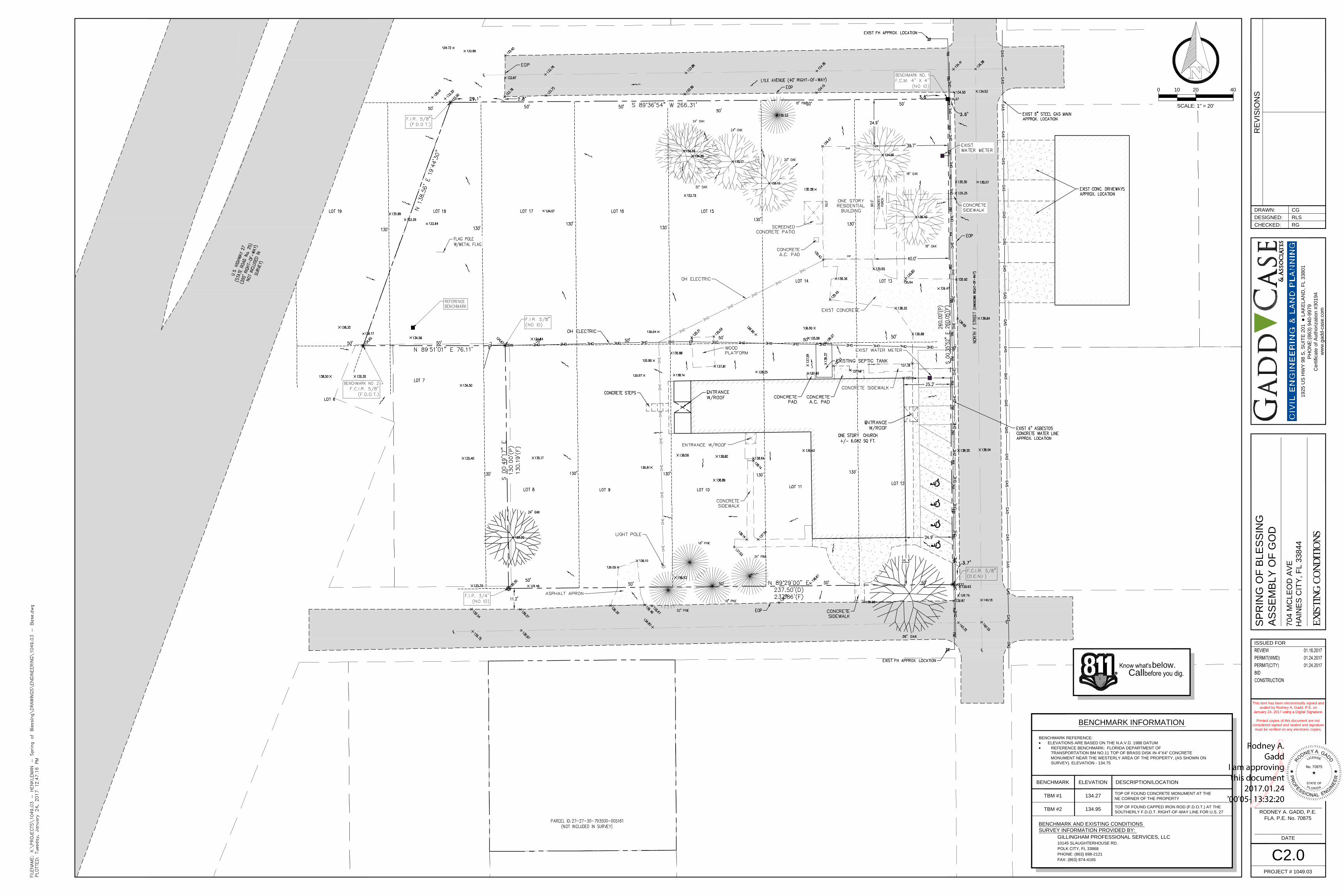
EXISTING CONDITIONS
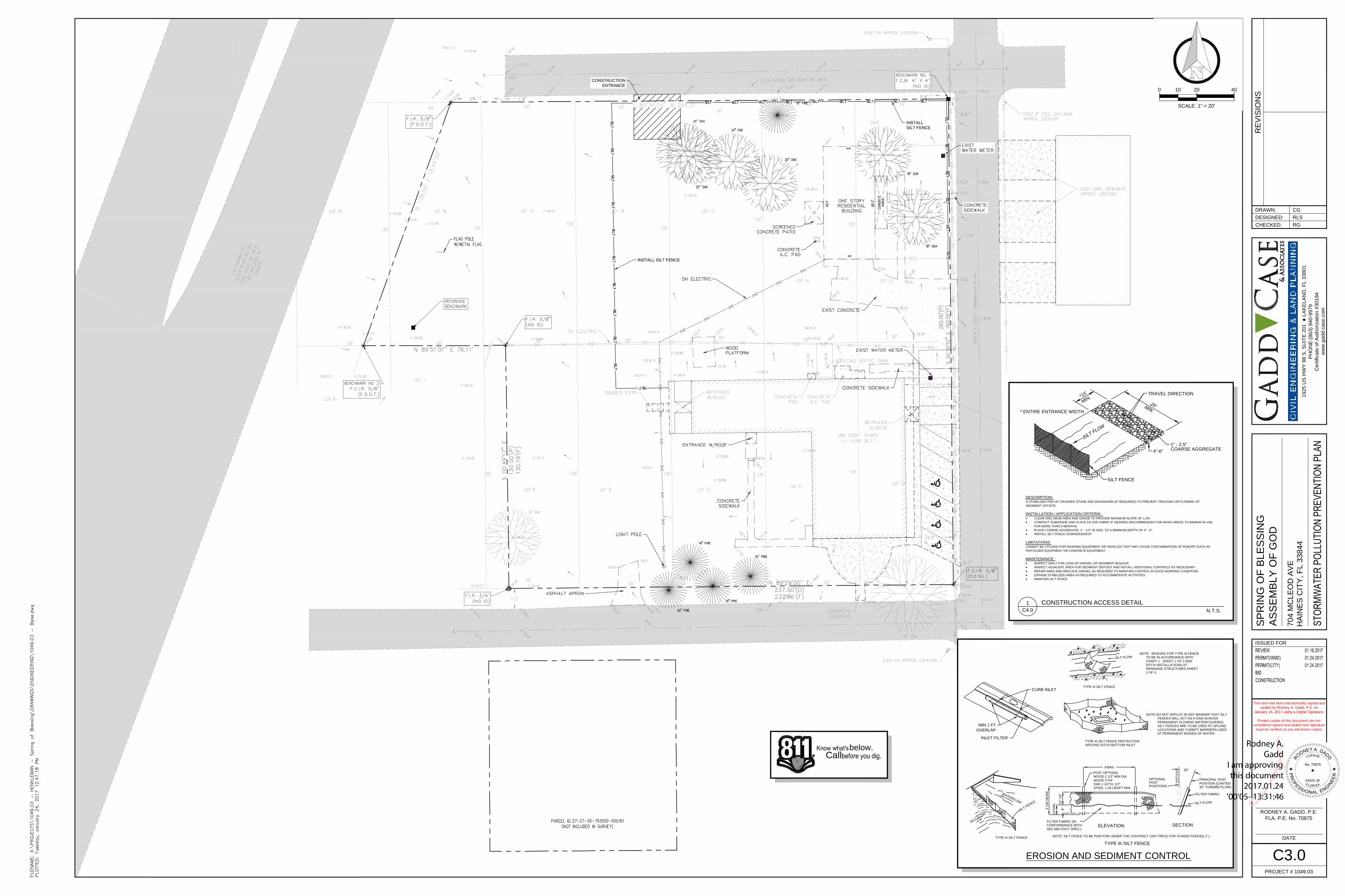
STORMWATER POLLUTION PREVENTION PLAN
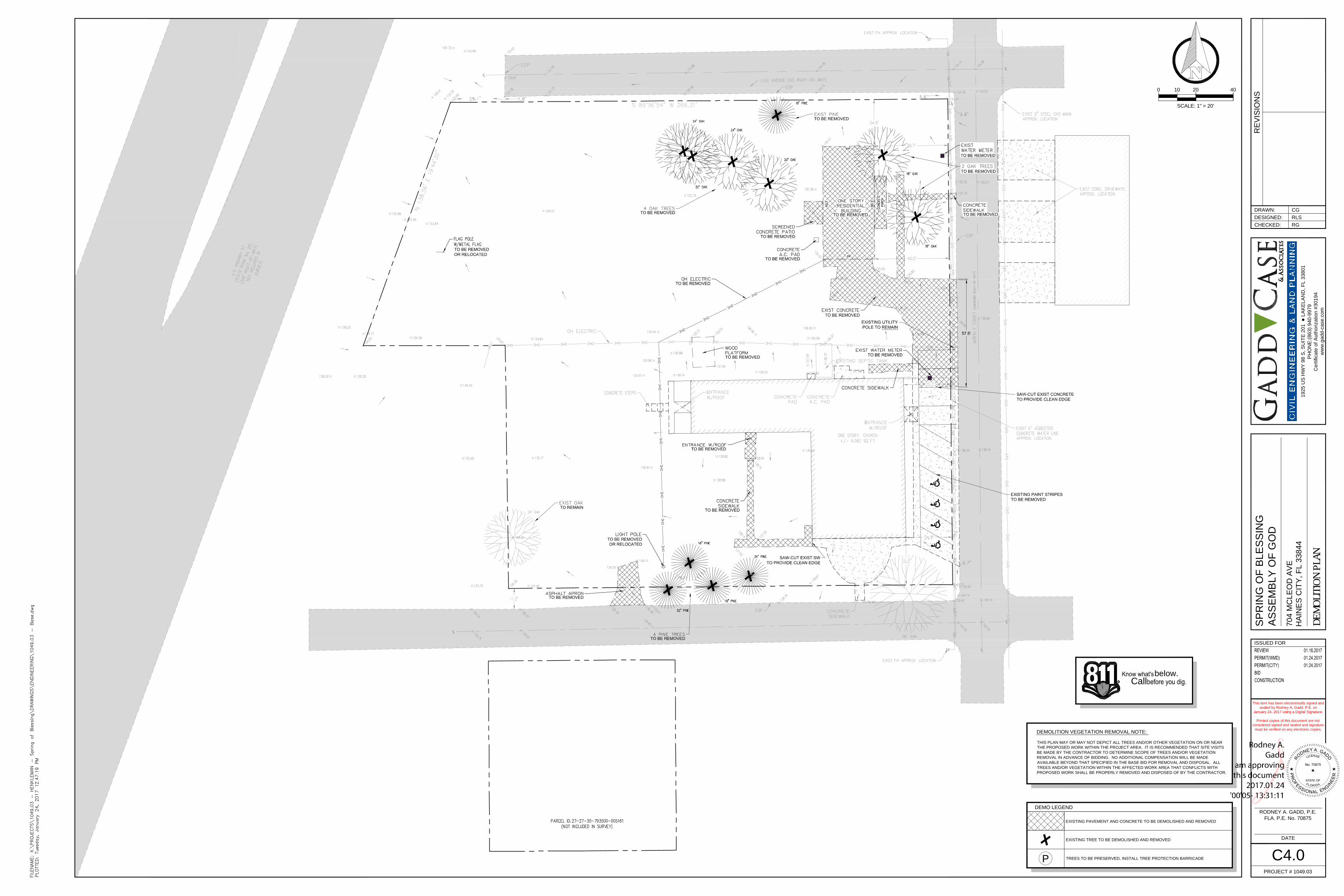
DEMOLITION PLAN
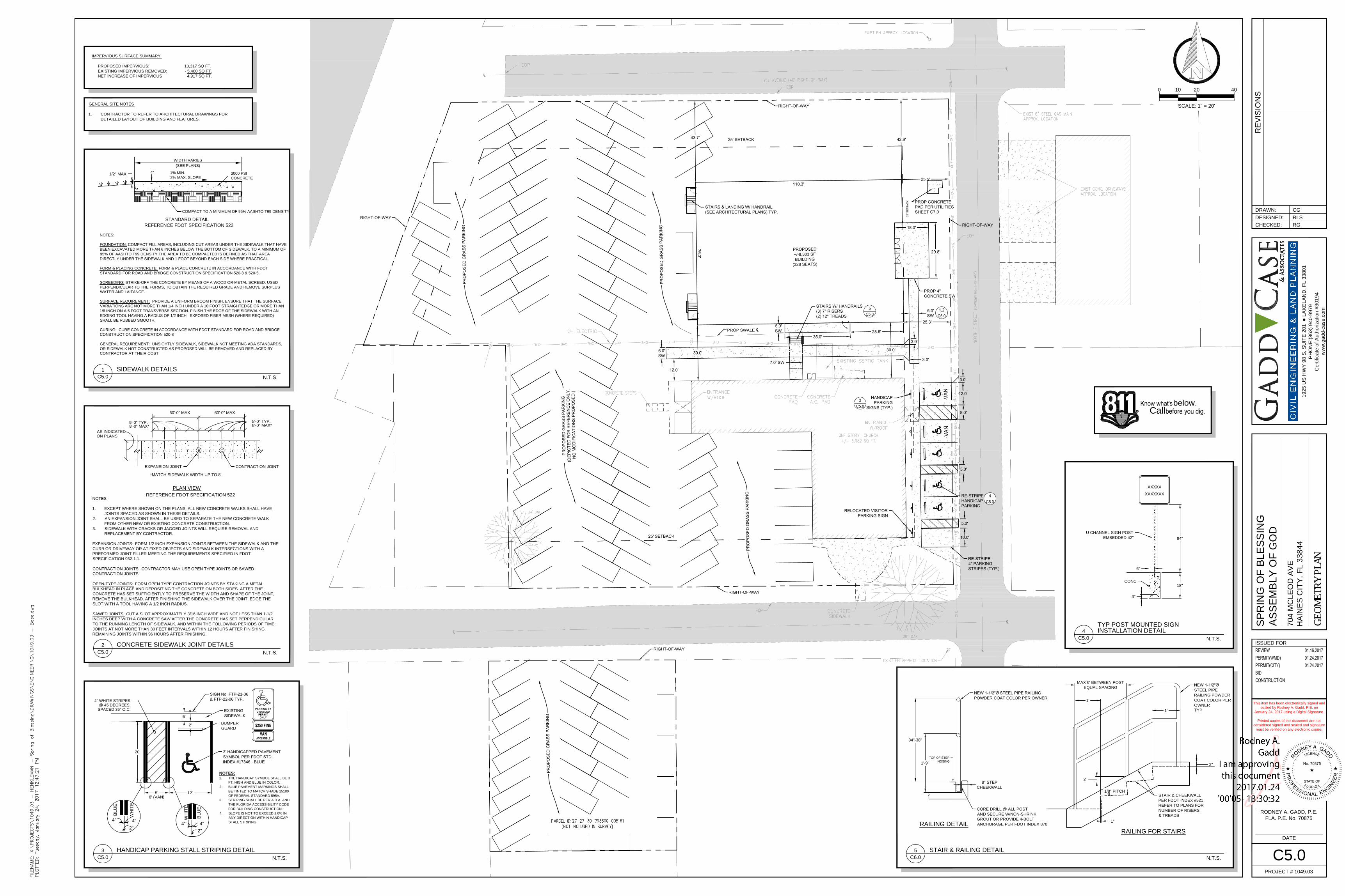
GEOMETRY PLAN
GRADING & DRAINAGE PLAN
UTILITIES PLAN
UTILITIES DETAILS
LANDSCAPE PLAN
CONSTRUCTION MATERIALS, QUALITY, AND WORKMANSHIP
SHALL BE IN ACCORDANCE WITH HAINES CITY AND FDOT
SPECIFICATIONS AND STANDARDS, AND THE MANUAL ON
UNIFORM TRAFFIC CONTROL DEVICES.
CONTRACTOR IS RESPONSIBLE FOR HIRING A QUALIFIED
UNDERGROUND UTILITY LOCATOR. THE UNDERGROUND
UTILITY LOCATOR SHALL LOCATE EXISTING UTILITIES IN
PROJECT AREA PRIOR TO DEMOLITION AND CONSTRUCTION.
SURVEY (BY OTHERS)
DATE
RODNEY A. GADD, P.E.
FLA. P.E. No. 70875
SP
RIN
G O
F B
LE
SS
IN
G
AS
SE
MB
LY
O
F G
OD
704 M
CLE
OD
A
VE
HA
IN
ES
C
IT
Y, F
L 33844
RE
VIS
IO
NS
PROJECT # 1049.03
19
25
U
S H
WY
9
8 S
, S
UIT
E 2
01
●
L
AK
EL
AN
D, F
L 3
38
01
PH
ON
E:(8
63
) 9
40
-9
97
9
Ce
rtifica
te
o
f A
uth
oriza
tio
n #
30
19
4
ww
w.g
ad
d-ca
se
.co
m
DRAWN:
DESIGNED:
CHECKED:
ISSUED FOR
CG
RLS
RG
This item has been electronically signed and
sealed by Rodney A. Gadd, P.E. on
January 24, 2017 using a Digital Signature.
Printed copies of this document are not
considered signed and sealed and signature
must be verified on any electronic copies.
C0.0
COVE
R SH
EET
IT IS THE INTENTION OF THESE DOCUMENTS TO PROPOSE
CONSTRUCTION IN ACCORDANCE WITH THE FLORIDA
BUILDING CODE AND FLORIDA ACCESSIBILITY CODE (LATEST
EDITION). CONTRACTOR SHALL BE FAMILIAR WITH THESE
DOCUMENTS AND ASSURE CONFORMANCE.
PROJECT LOCATION
MCLEOD AVE
NO
RT
H F
S
T
LYLE AVE
U
S
H
W
Y
2
7
PROJECT LOCATION
PARCEL 1:
LOT 8 LESS THE WEST 12.5 FEET THEREOF, LOTS 9 THROUGH 12, INCLUSIVE, LOT 17 AND THAT
PART OF LOTS 18 AND 19 LYING EAST OF THE RIGHT-OF-WAY LINE OF U.S. HIGHWAY 27 (STATE
ROAD 25), BLOCK J, TRACY TERRACE ADDITION, ACCORDING TO THE PLAT THEREOF AS
RECORDED IN PLAT BOOK 5, PAGE 41 OF THE PUBLIC RECORDS OF POLK COUNTY, FLORIDA.
PARCEL 2:
LOT 16, BLOCK J, TRACY TERRACE ADDITION, ACCORDING TO THE PLAT THEREOF AS RECORDED
IN PLAT BOOK 5, PAGE 41 OF THE PUBLIC RECORDS OF POLK COUNTY, FLORIDA.
PARCEL 3:
LOTS 13, 14 AND 15, BLOCK J, TRACY TERRACE ADDITION, ACCORDING TO THE PLAT THEREOF AS
RECORDED IN PLAT BOOK 5, PAGE 41 OF THE PUBLIC RECORDS OF POLK COUNTY, FLORIDA.
LANGSTON AVE
PARCEL ID: 27-27-30-793500-005161
PARCEL ID: 27-27-30-790900-010080
(NOT INCLUDED)
THE FOLLOWING LIST CONTAINS ABBREVIATIONS USED IN THIS SET OF DRAWINGS. NOTE THAT NOT ALL ABBREVIATIONS
SHOWN HERE MIGHT APPEAR WITHIN THIS SET OF PLANS
AC = ASPHALT CONCRETE
AC = ACRE
ALUM = ALUMINUM
APPD = APPROVED
APPROX = APPROXIMATE
ARCH = ARCHITECTURAL
ASPH = ASPHALT
ASSY = ASSEMBLY
AWWA = AMERICAN WATER
WORKS ASSOCIATION
BFO = BURIED FIBER OPTIC
BLDG = BUILDING
BLVD = BOULEVARD
BM = BENCHMARK
BC = BOTTOM OF CURB
BFP = BACK FLOW PREVENTER
BT = BURIED TELEPHONE
CF = CUBIC FEET
CHDPE = CORRUGATED HIGH DENSITY
POLYETHYLENE PIPE
CI = CAST IRON
CL = CENTER LINE
CLF = CHAIN LINK FENCE
CMP = CORRAGATED METAL PIPE
CO = CLEAN OUT, COMPANY
COL = CITY OF LAKELAND
COMM = COMMUNICATION
CONC = CONCRETE
COND = CONDUIT (UNDERGROUND)
CONST. = CONSTRUCT, CONSTRUCTION
CONTR = CONTRACTOR, CONTRACT
CORR = CORRUGATED
CU = CUBIC
CU.FT. = CUBIC FOOT
CU.IN. = CUBIC INCH
CY = CUBIC YARD
DBI = DITCH BOTTOM INLET
DBL = DOUBLE
DEMO = DEMOLITION
DET = DETAIL
DI = DUCTILE IRON
DIA = DIAMETER
DIM = DIMENSION
DIP = DUCTILE IRON PIPE
DS = DOWNSPOUT, DOWNSTREAM
DWG = DRAWING
DHWL = DESIGN HIGH WATER LEVEL
E = EAST
EA = EACH
EL = ELEVATION
ELEC = ELECTRIC, ELECTRICAL
ENCL = ENCLOSURE
EOP = EDGE OF PAVEMENT
EOL = EDGE OF LANE
EP = EDGE OF PAVEMENT ELEVATION
EQ = EQUAL
ERCP = ELLIPTICAL REINFORCED
CONCRETE PIPE
EXIST = EXISTING
EXP = EXPANSION CONT.
EXP JT = EXPANSION JOINT
EXT = EXTERIOR
FAR = FLOOR AREA RATIO
FDC = FIRE DEPARTMENT CONNECTION
FDOT = FLORIDA DEPARTMENT OF
TRANSPORTATION
FF = FINISHED FLOOR
FH = FIRE HYDRANT
FLG = FLANGE
FM = FORCE MAIN
FT (') = FEET, FOOT
GA = GAUGE
GALV = GALVANIZED
GR = GRADE
GRBR = GRADE BREAK
GRND = GROUND
GS = GALVANIZED STEEL, GROUND SHOT
GV = GATE VALVE
HB = HOSE BIB
HC = HANDICAP
HDPE = HIGH DENSITY POLYETHYLENE PIPE
HORIZ = HORIZONTAL
HP = HIGH POINT
HT = HEIGHT
HW = HIGH WATER
HWY = HIGHWAY
HYD = HYDRANT, HYDRAULIC
ID = INSIDE DIAMETER
IE = INVERT ELEVATION
IN (") = INCH
INC = INCORPORATED
INFO = INFORMATION
INV = INVERT
IRR = IRRIGATION
ISAR = IMPERVIOUS SURFACE AREA RATIO
JCT = JUNCTION
JMH = JUNCTION MANHOLE
JT = JOINT, CONSTRUCTION JOINT
L, LT = LEFT
LAT = LATERAL
LF = LINEAR FEET
LH = LEFT HAND
LP = LOW POINT
LVL = LEVEL
MAT = MATERIAL
MAX = MAXIMUM
MECH = MECHANICAL
MES = MITERED END SECTION
MEG = MATCH EXISTING GRADE
MFG = MANUFACTURING
MFGR = MANUFACTURER
MH = MANHOLE
MIN = MINIMUM
MISC = MISCELLANEOUS
MJ = MECHANICAL JOINT
MOD = MODIFIED
N = NORTH
NGS = NATIONAL GEODETIC SURVEY
NO (#) = NUMBER
NOM = NOMINAL
NTS = NOT TO SCALE
OC = ON CENTER
OD = OUTSIDE DIAMETER
OPP = OPPOSITE
ORIG = ORIGINAL
ORN = ORNAMENTAL
OH = OVERHEAD
PAR = PARALLEL
PC = PRECAST CONCRETE,
POINT OF CURVATURE
PERF = PERFORATED
PERM = PERMANENT
PERP = PERPENDICULAR
PI = POINT OF INTERSECTION
PIV = POST INDICATOR VALVE
PL = PROPERTY LINE, PLATE
PREFAB = PREFABRICATED
PRC = POINT OF REVERSE CURVATURE
PROJ = PROJECT
PROP = PROPOSED
PSF = POUNDS PER SQUARE FOOT
PSI = POUNDS PER SQUARE INCH
PT = POINT, POINT OF TANGENCY
PVC = POLYVINYL CHLORIDE
PVMT = PAVEMENT
R, RT = RIGHT
RAD = RADIUS
RCP = REINFORCED CONCRETE PIPE
RD = ROAD, ROOF DRAIN
RED = REDUCER
REQ'D = REQUIRED
REV = REVISION, REVISE
RH = RIGHT HAND
RM = ROOM
RND = ROUND
ROT = ROTATED
ROW, R/W = RIGHT OF WAY
RR = RAILROAD
S = SOUTH
SAN = SANITARY
SCH = SCHEDULE
SECT = SECTION
SEW = SEWER
SF, SQ FT = SQUARE FEET
SH = SHEET
SIM = SIMILAR
SLV = SLEEVE
SPEC = SPECIFICATION
SPR = SPRINKLER
SQ = SQUARE
SST = STAINLESS STEEL
ST = STREET
STA = STATION
STD = STANDARD
STL = STEEL
STRUC = STRUCTURAL
SY, SQYD = SQUARE YARDS
SYS = SYSTEM
SW = SIDEWALK
SHWL = SEASONAL HIGH WATER LEVEL
TAN = TANGENT
TBD = TO BE DETERMINED
TC = TOP OF CONC, TOP OF CURB,
TIME OF CONCENTRATION
TEL = TELEPHONE
TEMP = TEMPERATURE, TEMPORARY
TERM = TERMINAL, TERMINATE
TOB = TOP OF BERM, TOP OF BANK
TOP = TOP OF PAVEMENT
TOS = TOE OF SLOPE
TOW = TOP OF WALL
TR = TREAD
TS = TOP OF SIDEWALK
TV = TELEVISION
TYP = TYPICAL
T&B = TOP AND BOTTOM
UG = UNDERGROUND
US = UPSTREAM
VCP = VITRIFIED CLAY PIPE
VERT = VERTICAL
VPI = VERTICAL POINT OF INTERSECTION
VUA = VEHICLE USE AREA
WM = WATER MAIN
W = WEST, WIDTH, WATT
W/ = WITH
W/O = WITHOUT
WD = WOOD
WL = WATER LINE
WT = WEIGHT
WWF = WELDED WIRE FABRIC
X-SEC = CROSS SECTION
YD = YARD
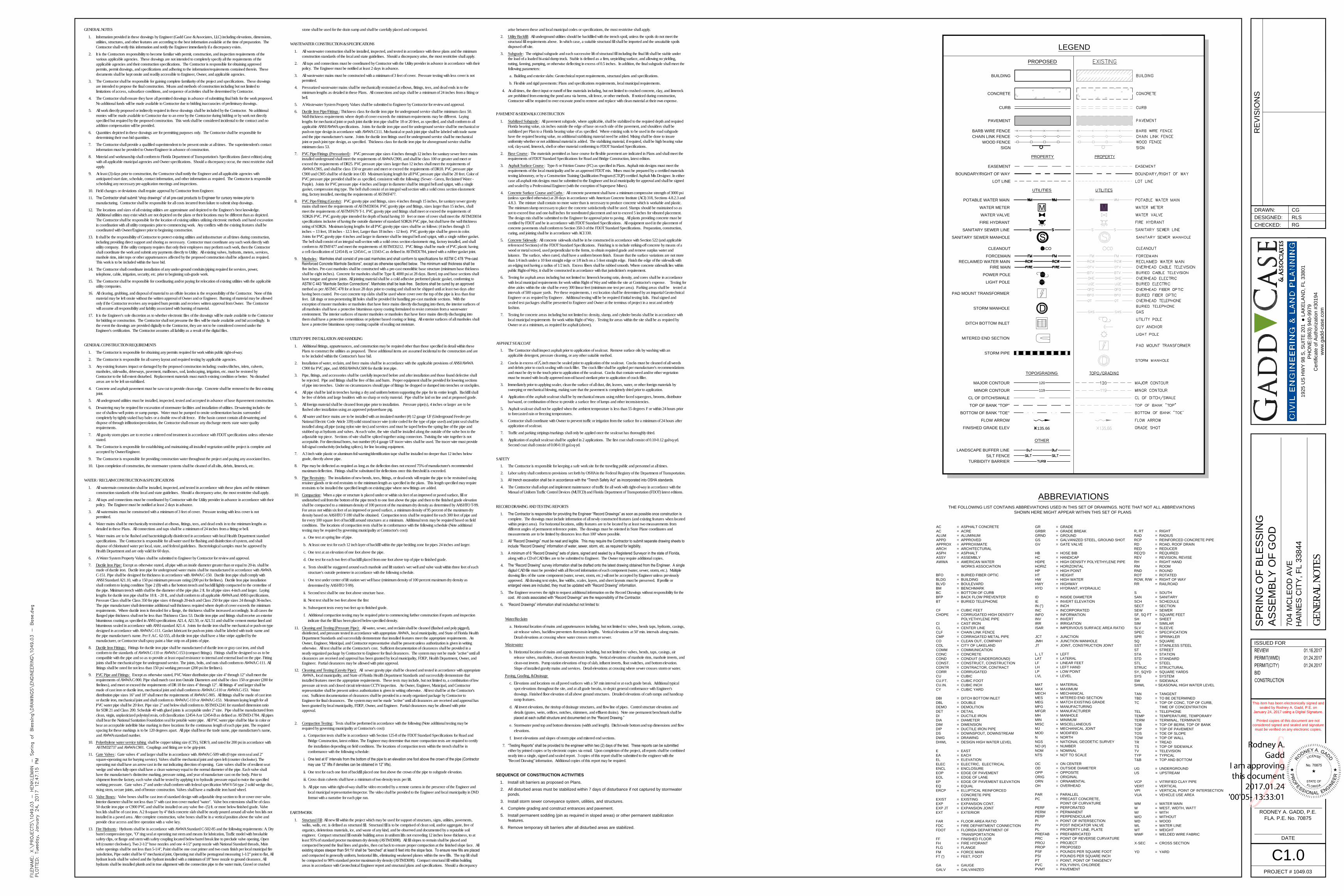
ABBREVIATIONS
135.66
BUILDING
CONCRETE
CURB
PAVEMENT
BARB WIRE FENCE
CHAIN LINK FENCE
WOOD FENCE
FIRE MAIN
FORCEMAIN
SANITARY SEWER LINE
POTABLE WATER MAIN
RECLAIMED WATER MAIN
SANITARY SEWER MANHOLE
STORM MANHOLE
LIGHT POLE
PAD MOUNT TRANSFORMER
POWER POLE
TURBIDITY BARRIER
SILT FENCE
LANDSCAPE BUFFER LINE
120
119
MAJOR CONTOUR
MINOR CONTOUR
CL OF DITCH/SWALE
TOP OF BANK "TOP"
BOTTOM OF BANK "TOE"
EASEMENT
BOUNDARY/RIGHT OF WAY
LOT LINE
PROPERTY
UTILITIES
WATER METER
WATER VALVE
M
COCLEANOUT
Y
FIRE HYDRANT
FLOW ARROW
FINISHED GRADE ELEV
TOPO/GRADING
LEGEND
DITCH BOTTOM INLET
MITERED END SECTION
STORM PIPE
PROPOSED
OTHER
SIGN
GENERAL NOTES
1. Information provided in these drawings by Engineer (Gadd Case & Associates, LLC) including elevations, dimensions,utilities, structures, and other features are according to the best information available at the time of preparation. TheContractor shall verify this information and notify the Engineer immediately if a discrepancy exists.
2. It is the Contractors responsibility to become familiar with permit, construction, and inspection requirements of thevarious applicable agencies. These drawings are not intended to completely specify all the requirements of theapplicable agencies and their construction specifications. The Contractor is responsible for obtaining approvedpermits, permit drawings, and specifications and adhering to the information/requirements contained therein. Thesedocuments shall be kept onsite and readily accessible to Engineer, Owner, and applicable agencies.
3. The Contractor shall be responsible for gaining complete familiarity of the project and specifications. These drawingsare intended to propose the final construction. Means and methods of construction including but not limited tolimitations of access, subsurface conditions, and sequence of activities shall be determined by Contractor.
4. The Contractor shall ensure they have all permitted drawings in advance of submitting final bids for the work proposed.No additional funds will be made available to Contractor due to bidding inaccuracies of preliminary drawings.
5. All work directly proposed or indirectly required in these drawings shall be included by the Contractor. No additionalmonies will be made available to Contractor due to an error by the Contractor during bidding or by work not directlyspecified but required by the proposed construction. This work shall be considered incidental to the contract and noaddition compensation will be provided.
6. Quantities depicted in these drawings are for permitting purposes only. The Contractor shall be responsible fordetermining their own bid quantities.
7. The Contractor shall provide a qualified superintendent to be present onsite at all times. The superintendent's contactinformation must be provided to Owner/Engineer in advance of construction.
8. Material and workmanship shall conform to Florida Department of Transportation's Specifications (latest edition) alongwith all applicable municipal agencies and Owner specifications. Should a discrepancy occur, the most restrictive shallapply.
9. At least (3) days prior to construction, the Contractor shall notify the Engineer and all applicable agencies withanticipated start date, schedule, contact information, and other information as required. The Contractor is responsiblescheduling any necessary pre-application meetings and inspections.
10. Field changes or deviations shall require approval by Contractor from Engineer.11. The Contractor shall submit “shop drawings” of all pre-cast products to Engineer for cursory review prior to
manufacturing. Contractor shall be responsible for all costs incurred from failure to submit shop drawings.12. The locations and sizes of all existing utilities are approximate and depicted to the Engineer's best knowledge.
Additional utilities may exist which are not depicted on the plans or their locations may be different than as depicted.The Contractor shall be responsible for the location of existing utilities utilizing electronic methods and hand excavationin coordination with all utility companies prior to commencing work. Any conflicts with the existing features shall becoordinated with Owner/Engineer prior to beginning construction.
13. It shall be the responsibility of Contractor to protect existing utilities and infrastructure at all times during construction,including providing direct support and shoring as necessary. Contractor must coordinate any such work directly withutility company. If the utility company requires that only their employees may perform such work, then the Contractorshall coordinate the work and submit any payments directly to Utility. All existing valves, hydrants, meters, services,manhole rims, inlet tops or other appurtenances affected by the proposed construction shall be adjusted as required.This work is to be included within the base bid.
14. The Contractor shall coordinate installation of any under-ground conduits/piping required for services, power,telephone, cable, irrigation, security, etc. prior to beginning sub-grade work.
15. The Contractor shall be responsible for coordinating and/or paying for relocation of existing utilities with the applicableutility companies.
16. All clearing, grubbing, and disposal of material to an offsite location is the responsibility of the Contractor. None of thismaterial may be left onsite without the written approval of Owner and or Engineer. Burning of material may be allowedonly if the Contractor receives any required burn permits and receives written approval from Owner. The Contractorwill assume all responsibility and liability associated with burning of material.
17. It is the Engineer's sole discretion as to whether electronic files of the drawings will be made available to the Contractorfor bidding or construction. The Contractor shall not presume the files will be made available and bid accordingly. Inthe event the drawings are provided digitally to the Contractor, they are not to be considered covered under theEngineer's certification. The Contractor assumes all liability as a result of the digital files.
GENERAL CONSTRUCTION REQUIREMENTS
1. The Contractor is responsible for obtaining any permits required for work within public right-of-way.2. The Contractor is responsible for all survey layout and required testing by applicable agencies.3. Any existing features impact or damaged by the proposed construction including: swales/ditches, inlets, culverts,
manholes, sidewalks, driveways, pavement, mailboxes, sod, landscaping, irrigation, etc. must be restored byContractor to the full extent disturbed. Replacement materials must match existing condition or better. No disturbedareas are to be left un-stabilized.
4. Concrete and asphalt pavement must be saw cut to provide clean edge. Concrete shall be removed to the first existingjoint.
5. All underground utilities must be installed, inspected, tested and accepted in advance of base & pavement construction.6. Dewatering may be required for excavation of stormwater facilities and installation of utilities. Dewatering includes the
use of shallow well points or sump pumps. Water must be pumped to onsite sedimentation basins surroundedcompletely by tightly staked hay bales or a double row of silt fence. If the basin cannot contain all dewatering anddispose of through infiltration/percolation, the Contractor shall ensure any discharge meets state water qualityrequirements.
7. All gravity storm pipes are to receive a mitered end treatment in accordance with FDOT specifications unless otherwisestated.
8. The Contractor is responsible for establishing and maintaining all installed vegetation until the project is complete andaccepted by Owner/Engineer.
9. The Contractor is responsible for providing construction water throughout the project and paying any associated fees.10. Upon completion of construction, the stormwater systems shall be cleaned of all silts, debris, limerock, etc.
WATER / RECLAIM CONSTRUCTION & SPECIFICATIONS
1. All watermain construction shall be installed, inspected, and tested in accordance with these plans and the minimumconstruction standards of the local and state guidelines. Should a discrepancy arise, the most restrictive shall apply.
2. All taps and connections must be coordinated by Contractor with the Utility provider in advance in accordance with theirpolicy. The Engineer must be notified at least 2 days in advance.
3. All watermains must be constructed with a minimum of 3 feet of cover. Pressure testing with less cover is notpermitted.
4. Water mains shall be mechanically restrained at elbows, fittings, tees, and dead ends in to the minimum lengths asdetailed in these Plans. All connections and taps shall be a minimum of 24 inches from a fitting or bell.
5. Water mains are to be flushed and bacteriologically disinfected in accordance with local Health Department standardspecifications. The Contractor is responsible for all water used for flushing and disinfection of system, and shalldispose of chlorinated water per local, state, and federal guidelines. Bacteriological samples must be approved byHealth Department and are only valid for 60 days.
6. A Water System Property Values shall be submitted to Engineer by Contractor for review and approval.7. Ductile Iron Pipe: Except as otherwise stated, all pipe with an inside diameter greater than or equal to 20-in. shall be
made of ductile iron. Ductile iron pipe for underground water mains shall be manufactured in accordance with AWWAC-151. Pipe shall be designed for thickness in accordance with AWWA C-150. Ductile Iron pipe shall comply withANSI Standard A21.10, with a 150 psi minimum pressure rating (200 psi for firelines). Ductile Iron pipe installationshall conform to laying condition Type 2 (B) with a flat bottom trench and backfill lightly compacted to the centerline ofthe pipe. Minimum trench width shall be the diameter of the pipe plus 2 ft. for all pipe sizes 4-inch and larger. Layinglengths for ductile iron pipe shall be 18 ft. - 20 ft., and shall conform to all applicable AWWA and ANSI specifications.Pressure Class shall be Class 350 for pipe sizes 4 through 20-inch and Class 250 for pipe sizes 24 through 36-inches.The pipe manufacturer shall determine additional wall thickness required where depth of cover exceeds the minimumrequirements. Where ductile iron is threaded for a flange, the thickness shall be increased accordingly. In all cases theflanged pipe thickness shall not be less than Thickness Class 53. Ductile iron pipe and fittings shall receive an exteriorbituminous coating as specified in ANSI specifications A21.4, A21.50, or A21.51 and shall be cement mortar lined andbituminous sealed in accordance with ANSI standard A21.4. Joints for ductile iron shall be mechanical or push-on typedesigned in accordance with AWWA C-111. Gasket lubricant for push-on joints shall be labeled with trade name andthe pipe manufacturer's name. Per F.A.C. 62-555, all ductile iron pipe shall have a blue stripe applied by themanufacturer, or Contractor shall spray paint a blue strip on all joints of pipe.
8. Ductile Iron Fittings: Fittings for ductile iron pipe shall be manufactured of ductile iron or gray cast iron, and shallconform to the standards of AWWA C-110 or AWWA C-153 (compact fittings). Fittings shall be designed so as to becompatible with the pipe and so as to provide at least equal resistance to internal and external load on the pipe. Fittingjoints shall be mechanical type for underground service. The joints, bolts, and nuts shall conform to AWWA C-111. Allfittings shall be rated for not less than 150 psi working pressure (200 psi for firelines).
9. PVC Pipe and Fittings: Except as otherwise stated, PVC Water distribution pipe size 4" through 12" shall meet therequirements of AWWA C-900. Pipe shall match cast iron Outside Diameters and shall be class 150 or greater (200 forfirelines), and meet or exceed the requirements of DR 18 for sizes 4" through 12". All fittings 4" and larger shall bemade of cast iron or ductile iron, mechanical joint and shall conform to AWWA C-110 or AWWA C-153. Waterdistribution pipe sizes 16" and 18" shall meet the requirements of AWWA C-905. All fittings shall be made of cast ironor ductile iron, mechanical joint and shall conform to AWWA C-110 or AWWA C-153. Maximum laying length for allPVC water pipe shall be 20 feet. Pipe size 2" and below shall conform to ASTM D-2241 for standard dimension ratiofor SDR 21 and Class 200. Schedule 40 with glued joints is acceptable under 2" size. Pipe shall be manufactured fromclean, virgin, unplasticized polyvinyl resin, cell classification 12454-A or 12454-B as defined as ASTM D-1784. All pipesshall bear the National Sanitation Foundation seal for potable water pipe. All PVC water pipe shall be blue in color orbear an acceptable indelible blue marking in three locations for the continuous length of each pipe joint. The requiredspacing for these markings is to be 120 degrees apart. All pipe shall bear the trade name, pipe manufacturer's name,and AWWA standard number.
10. Polyethylene water service tubing shall be copper tubing size (CTS), SDR 9, and rated for 200 psi in accordance withASTM D2737 and AWWA C901. Couplings and fitting are to be grip-joint.
11. Gate Valves: Gate valves 4" and larger shall be in accordance with AWWA C-509 with (0 type stem seal and 2"square-operating nut for burying service). Valves shall be mechanical joint and open left (counter clockwise). Theoperating nut shall have an arrow cast in the nut indicating direction of opening. Gate valves shall be of resilient seatwedge and when fully open shall have a clean waterway equal to the normal diameter of the pipe. Each valve shallhave the manufacturer's distinctive marking, pressure rating, and year of manufacture cast on the body. Prior toshipment from the factory, each valve shall be tested by applying it to hydraulic pressure equal to twice the specifiedworking pressure. Gate valves 2" and under shall conform with federal specification WW-V-54 type 2 solid wedge disc,rising stem, secure joints, and of bronze construction. Valves shall have a malleable iron hand wheel.
12. Valve Boxes: Valve boxes shall be cast iron of standard design with adjustable drop section to fit or cover over valve.Interior diameter shall be not less than 5" with cast iron cover marked "water". Valve box extensions shall be of class50 ductile iron pipe or C900 PVC and shall be installed on any valve five- (5) ft. or more below finished grade. Valvebox lids shall be of cast iron. A 2 ft-square by 4" thick concrete slab shall be neatly poured around all valve box lids notinstalled in a paved area. After complete construction, valve boxes shall be in a vertical position above the valve andprovide clear access and free operation with a valve key.
13. Fire Hydrants: Hydrants shall be in accordance with AWWA Standard C-502-85 and the following requirements: A. Drybarrel compression type, "O" ring seal at operating nut stem and means for lubrication, Traffic model with breakablesafety clips, or flange and stem with safety coupling located below barrel break line to preclude valve opening, Openleft (counter clockwise), Two 2-1/2" hose nozzles and one 4-1/2" pump nozzle with National Standard threads, Mainvalve openings shall be not less than 5-1/4", Paint shall be one coat primer and two coats finish per local municipal firejurisdiction, Pipe outlet shall be 6" mechanical joint, Operating nut shall be pentagonal measuring 1-1/2" point to flat, Allhydrant leads shall be valved and the hydrant installed with a minimum of 18" hose nozzle to ground clearance, Allhydrants shall be installed plumb and in true alignment with the connection pipe to the water main, Gravel or crushed
stone shall be used for the drain sump and shall be carefully placed and compacted.
WASTEWATER CONSTRUCTION & SPECIFICATIONS
1. All wastewater construction shall be installed, inspected, and tested in accordance with these plans and the minimumconstruction standards of the local and state guidelines. Should a discrepancy arise, the most restrictive shall apply.
2. All taps and connections must be coordinated by Contractor with the Utility provider in advance in accordance with theirpolicy. The Engineer must be notified at least 2 days in advance.
3. All wastewater mains must be constructed with a minimum of 3 feet of cover. Pressure testing with less cover is notpermitted.
4. Pressurized wastewater mains shall be mechanically restrained at elbows, fittings, tees, and dead ends in to theminimum lengths as detailed in these Plans. All connections and taps shall be a minimum of 24 inches from a fitting orbell.
5. A Wastewater System Property Values shall be submitted to Engineer by Contractor for review and approval.6. Ductile Iron Pipe/Fittings : Thickness class for ductile iron pipe for underground service shall be minimum class 50.
Wall thickness requirements where depth of cover exceeds the minimum requirements may be different. Layinglengths for mechanical joint or push joint ductile iron pipe shall be 18 or 20 feet, as specified, and shall conform to allapplicable ANSI/AWWA specifications. Joints for ductile iron pipe used for underground service shall be mechanical orpush-on type design in accordance with AWWA C111. Mechanical or push joint pipe shall be labeled with trade nameand the pipe manufacturer's name. Joints for ductile iron fittings used for underground service shall be mechanicaljoint or push joint type design, as specified. Thickness class for ductile iron pipe for aboveground service shall beminimum class 53.
7. PVC Pipe/Fittings (Pressurized) : PVC pressure pipe sizes 4 inches through 12 inches for sanitary sewer force mainsinstalled underground shall meet the requirements of AWWA C900, and shall be class 100 or greater and meet orexceed the requirements of DR25. PVC pressure pipe sizes larger than 12 inches shall meet the requirements ofAWWA C905, and shall be class 150 or greater and meet or exceed the requirements of DR18. PVC pressure pipeC900 and C905 shall be of ductile iron OD. Maximum laying length for all PVC pressure pipe shall be 20 feet. Color ofPVC pressure pipe provided shall be as specified, consistent with the following: (Sewer - Green, Reclaimed Water -Purple). Joints for PVC pressure pipe 4 inches and larger in diameter shall be integral bell and spigot, with a singlegasket, compression ring type. The bell shall consist of an integral wall section with a solid cross section elastomericring, factory installed, meeting the requirements of ASTM F477.
8. PVC Pipe/Fitting (Gravity) : PVC gravity pipe and fittings, sizes 4 inches through 15 inches, for sanitary sewer gravitymains shall meet the requirements of ASTM D3034. PVC gravity pipe and fittings, sizes larger than 15 inches, shallmeet the requirements of ASTM F679 T-1. PVC gravity pipe and fittings shall meet or exceed the requirements ofSDR26 PVC. PVC gravity pipe intended for depth of burial having 10 feet or more of cover shall meet the ASTM D3034specifications inclusive of having the outside diameter of standard SDR26 PVC pipe, but shall have the wall thicknessrating of SDR26. Maximum laying lengths for all PVC gravity pipe sizes shall be as follows: (4 inches through 15inches -- 13 feet, 18 inches - 12.5 feet, Larger than 18 inches - 12 feet). PVC gravity pipe shall be green in color.Joints for PVC gravity pipe 4 inches and larger in diameter shall be integral bell and spigot, with a single rubber gasket.The bell shall consist of an integral wall section with a solid cross section elastomeric ring, factory installed, and shallconform to ASTM F477 and meet the requirements of ASTM D3212. PVC fittings shall be made of PVC plastic havinga cell classification of 12454-B, or 12454-C, or 13343-C as defined in ASTM D1784, joined with a rubber gasket joint.
9. Manholes: Manholes shall consist of pre-cast manholes and shall conform to specifications for ASTM C 478 “Pre-castReinforced Concrete Manhole Sections”, except as otherwise specified below. The minimum wall thickness shall befive inches. Pre-cast manholes shall be constructed with a pre-cast monolithic base structure (minimum base thicknessshall be eight inches). Concrete for manholes shall be Type II, 4000 psi at 28 days. Barrel, top and base sections shallhave tongue and groove joints. All jointing material shall be a cold adhesive preformed plastic gasket, conforming toASTM C 443 “Manhole Section Connections”. Manholes shall be leak-free. Sections shall be cured by an approvedmethod as per ASTM C 478 for at least 28 days prior to coating and shall not be shipped until at least two days afterhaving been coated. Pre-cast concrete top slabs shall be used where cover over the top of the pipe is less than fourfeet. Lift rings or non-penetrating lift holes shall be provided for handling pre-cast manhole sections. With theexception of master manholes or manholes that have force mains directly discharging into them, the interior surfaces ofall manholes shall have a protective bituminous epoxy coating formulated to resist corrosion from a wastewaterenvironment. The interior surfaces of master manholes or manholes that have force mains directly discharging intothem shall have a protective cementitious or polymer based coating or lining. All exterior surfaces of all manholes shallhave a protective bituminous epoxy coating capable of sealing out moisture.
UTILITY PIPE INSTALLATION AND HANDLING
1. Additional fittings, appurtenances, and construction may be required other than those specified in detail within thesePlans to construct the utilities as proposed. These additional items are assumed incidental to the construction and areto be included within the Contractor's base bid.
2. Installation of water, reclaim, and force mains shall be in accordance with the applicable provisions of ANSI/AWWAC900 for PVC pipe, and ANSI/AWWA C600 for ductile iron pipe.
3. Pipe, fittings, and accessories shall be carefully inspected before and after installation and those found defective shallbe rejected. Pipe and fittings shall be free of fins and burrs. Proper equipment shall be provided for lowering sectionsof pipe into trenches. Under no circumstances should pipe of fittings be dropped or dumped into trenches or stockpiles.
4. All pipe shall be laid in trenches having a dry and uniform bottom supporting the pipe for its entire length. Backfill shallbe free of debris and large boulders with no sharp or rocky material. Pipe shall be laid on line and at proposed grade.
5. All foreign material shall be cleaned from pipe prior to installation. Pressure pipe(s), 4 inches or larger are to beflushed after installation using an approved polyurethane pig.
6. All water and force mains are to be installed with an insulated number (#) 12 gauge UF (Underground Feeder perNational Electric Code Article 339) solid strand tracer wire (color coded for the type of pipe used) and joint seal shall beinstalled along all pipe (using nylon wire ties) and services and must be taped below the spring line of the pipe andstubbed up at hydrants and valves. At each valve, the wire shall be installed along the outside of the valve box to theadjustable top piece. Sections of wire shall be spliced together using connectors. Twisting the wire together is notacceptable. For directional bores, two number (#) 4 gauge UF tracer wires shall be used. The tracer wire must providefull signal conductivity (including splices), for line locating equipment.
7. A 3 inch wide plastic or aluminum foil warning/identification tape shall be installed no deeper than 12 inches belowgrade, directly above pipe.
8. Pipe may be deflected as required as long as the deflection does not exceed 75% of manufacturer's recommendedmaximum deflection. Fittings shall be substituted for deflections once this threshold is exceeded.
9. Pipe Restraints: The installation of new bends, tees, fittings, or dead-ends will require the pipe to be restrained usingretainer glands or tie-rod restraints to the minimum length as specified in the plans. This length specified may requirerestraints to be installed the specified length on existing pipe where new fittings are added.
10. Compaction: When a pipe or structure is placed under or within six feet of an improved or paved surface, fill orundisturbed soil from the bottom of the pipe trench to one foot above the pipe and then to the finished grade elevationshall be compacted to a minimum density of 100 percent of the maximum dry density as determined by AASHTO T-99.For areas not within six feet of an improved or paved surface, a minimum density of 95 percent of the maximum drydensity based on AASHTO T-180 shall be obtained. Compaction tests shall be required for each 300 feet of pipe andfor every 100 square feet of backfill around structures at a minimum. Additional tests may be required based on fieldconditions. The locations of compaction rests shall be in conformance with the following schedule (Note additionaltesting may be required by governing municipality at Contractor's cost):a. One test at spring line of pipe.
b. At least one test for each 12 inch layer of backfill within the pipe bedding zone for pipes 24 inches and larger.
c. One test at an elevation of one foot above the pipe.
d. One test for each two feet of backfill placed from one foot above top of pipe to finished grade.
e. Tests should be staggered around each manhole and lift station's wet well and valve vault within three feet of eachstructure's outside perimeter in accordance with the following schedule.
i. One test under center of lift station wet well base (minimum density of 100 percent maximum dry density asdetermined by AASHTO T-99).
ii. Second test shall be one foot above structure base.
iii. Next test shall be two feet above the first
iv. Subsequent tests every two feet up to finished grade.
f. Additional compaction testing may be required prior to commencing further construction if reports and inspectionindicate that the fill has been placed below specified density.
11. Cleaning and Testing (Pressure Pipe): All water, sewer, and reclaim shall be cleaned (flushed and poly pigged),disinfected, and pressure tested in accordance with appropriate AWWA , local municipality, and State of Florida HealthDepartment Standards and successfully demonstrate that installed features meet the appropriate requirements. AnOwner, Engineer, Municipal, and Contractor representative shall be present unless authorization is given in writingotherwise. All test shall be at the Contractor's cost. Sufficient documentation of clearances shall be provided in aneatly organized package by Contractor to Engineer for final clearances. The system may not be made "active" until allclearances are received and approval has been granted by local municipality, FDEP, Health Department, Owner, andEngineer. Partial clearances may be allowed with prior approval.
12. Cleaning and Testing (Gravity Pipe): All sewer gravity pipe shall be cleaned and tested in accordance with appropriateAWWA , local municipality, and State of Florida Health Department Standards and successfully demonstrate thatinstalled features meet the appropriate requirements. These tests may include, but not limited to, a combination of lowpressure air tests and closed circuit television CCTV inspection. An Owner, Engineer, Municipal, and Contractorrepresentative shall be present unless authorization is given in writing otherwise. All test shall be at the Contractor'scost. Sufficient documentation of clearances shall be provided in a neatly organized package by Contractor toEngineer for final clearances. The system may not be made "active" until all clearances are received and approval hasbeen granted by local municipality, FDEP, Owner, and Engineer. Partial clearances may be allowed with priorapproval.
2. Compaction Testing : Tests shall be performed in accordance with the following (Note additional testing may berequired by governing municipality at Contractor's cost):a. Compaction tests shall be in accordance with Section 125-8 of the FDOT Standard Specifications for Road and
Bridge Construction, latest edition. The Engineer may determine that more compaction tests are required to certifythe installation depending on field conditions. The locations of compaction tests within the trench shall be inconformance with the following schedule:
i. One test at 6” intervals from the bottom of the pipe to an elevation one foot above the crown of the pipe (Contractormay use 12” lifts if densities can be obtained in 12” lifts).
ii. One test for each one foot of backfill placed one foot above the crown of the pipe to subgrade elevation.
iii. Cross drain culverts shall have a minimum of two density tests per lift.
b. All pipe runs within right-of-way shall be video recorded by a remote camera in the presence of the Engineer andlocal municipal representative/inspector. The video shall be provided to the Engineer and local municipality in DVDformat with a narrative for each pipe run.
EARTHWORK
1. Structural Fill : All new fill within the project which may be used for support of structures, signs, utilities, pavements,walks, walls, etc. is defined as structural fill. Structural fill is to be comprised of clean soil, and/or aggregate, free oforganics, deleterious materials, ice, and waste of any kind, and be observed and documented by a reputable soilengineer. Compact structural fill outside building areas in uniform lifts not exceeding 12 inches loose thickness, to atleast 95% of standard proctor maximum dry density (ASTM D698). All fill slopes to remain shall be placed andcompacted beyond the final lines and grades, then cut back to ensure proper compaction at the finished slope face. Allexisting slopes steeper than 5H:1V shall be “benched” at least 8 feet into the slope face. To ensure new fills are placedand compacted in generally uniform, horizontal lifts, eliminating weakened planes within the new fills. The top lift shallbe compacted to 98% standard proctor maximum dry density (ASTM D698). Compact structural fill within buildingareas in accordance with Geotechnical Engineer report and structural plans and specifications. Should a discrepancy
arise between these and local municipal codes or specifications, the most restrictive shall apply.2. Utility Backfill: All underground utilities should be backfilled with the trench spoil, unless the spoils do not meet the
structural fill requirements above. In which case, a suitable structural fill shall be imported and the unsuitable spoilsdisposed off site.
3. Subgrade: The original subgrade and each successive lift of structural fill including the final lift shall be stable underthe load of a loaded bi-axial dump truck. Stable is defined as a firm, unyielding surface, and allowing no yielding,rutting, fanning, pumping, or otherwise deflecting in excess of 0.5 inches. In addition, the final subgrade shall meet thefollowing parameters:a. Building and exterior slabs: Geotechnical report requirements, structural plans and specifications.
b. Flexible and rigid pavements: Plans and specifications requirements, local municipal requirements.
4. At all times, the direct input or runoff of fine materials including, but not limited to crushed concrete, clay, and limerockare prohibited from entering the pond area via berms, silt fence, or other methods. If noticed during construction,Contractor will be required to over excavate pond to remove and replace with clean material at their own expense.
PAVEMENT & SIDEWALK CONSTRUCTION
1. Stabilized Subgrade : All pavement subgrade, where applicable, shall be stabilized to the required depth and requiredFlorida bearing value, six inches outside the edge of base on each side of the pavement, and shoulders shall bestabilized per Plan to a Florida bearing value of as specified. Where existing soils to be used in the road subgradehave the required bearing value, no additional stabilizing material need be added. Mixing shall be done to insureuniformity whether or not additional material is added. The stabilizing material, if required, shall be high bearing valuesoil, clay-sand, limerock, shell or other material conforming to FDOT Standard Specifications.
2. Base Course: The materials permitted as base course for flexible pavement are indicated in Plans and shall meet therequirements of FDOT Standard Specifications for Road and Bridge Construction, latest edition.
3. Asphalt Surface Course : Type-S or Friction Course (FC) as specified in Plans. Asphalt mix designs must meet therequirements of the local municipality and be an approved FDOT mix. Mixes must be prepared by a certified materialstesting laboratory, or by a Construction Training Qualification Program (CTQP) certified Asphalt Mix Designer. In eithercase all asphalt mix designs must be submitted to the Engineer and local municipality for approval and shall be signedand sealed by a Professional Engineer (with the exception of Superpave Mixes).
4. Concrete Surface Course and Curbs : All concrete pavement shall have a minimum compressive strength of 3000 psi(unless specified otherwise) at 28 days in accordance with American Concrete Institute (ACI) 318, Sections 4.8.2.3 and4.8.3. The mixture shall contain no more water than is necessary to produce concrete which is workable and plastic.The minimum slump necessary to place the concrete satisfactorily shall be used. Slumps should be maintained so asnot to exceed four and one-half inches for nonvibrated placement and not to exceed 5 inches for vibrated placement.The design mix shall be submitted to the Engineer for approval prior to paving. All plants providing concrete must becertified by FDOT and be in accordance with FDOT Standard Specifications. All equipment used in the placement ofconcrete pavements shall conform to Section 350-3 of the FDOT Standard Specifications. Preparation, construction,curing, and jointing shall be in accordance with ACI 330.
5. Concrete Sidewalk : All concrete sidewalk shall be in be constructed in accordance with Section 522 (and applicablereferenced Sections) of the FDOT Standard Specifications. Finishing is to include striking-off concrete by means of awood or metal screed, used perpendicular to the forms, to obtain required grade and remove surplus water andlaitance. The surface, when cured, shall have a uniform broom finish. Ensure that the surface variations are not morethan 1/4 inch under a 10 foot straight edge or 1/8 inch on a 5 foot straight edge. Finish the edge of the sidewalk withan edging tool having a radius of 1/2 inch. Excess fibers shall be rubbed smooth. Where concrete sidewalk lies withinpublic Right-of-Way, it shall be constructed in accordance with that jurisdiction's requirement.
6. Testing for asphalt areas including but not limited to: limerock bearing ratio, density, and cores shall be in accordancewith local municipal requirements for work within Right of Way and within the site at Contractor's expense. Testing fordrive aisles within the site shall be every 300 linear feet (minimum one test per area). Parking areas shall be tested atintervals of 500 square yards. Per these requirements, t est location shall be determined by an impartial GeotechnicalEngineer or as required by Engineer . Additional testing will be be required if initial testing fails. Final signed andsealed test packages shall be presented to Engineer and Owner at the terminus of project in a neat and orderlyfashion.
7. Testing for concrete areas including but not limited to: density, slump, and cylinder breaks shall be in accordance withlocal municipal requirements for work within Right of Way . Testing for areas within the site shall be as required byOwner or at a minimum, as required for asphalt (above).
ASPHALT SEALCOAT1. The Contractor shall inspect asphalt prior to application of sealcoat. Remove surface oils by washing with an
applicable detergent, pressure cleaning, or any other suitable method.
2. Cracks in excess of 14 inch must be sealed prior to application of the sealcoat. Cracks must be cleaned of all weeds
and debris prior to crack sealing with crack filler. The crack filler shall be applied per manufacturer's recommendationsand must be dry to the touch prior to application of the sealcoat. Cracks that contain weed and/or other vegetationmust be treated with locally approved non-oil based sterilant prior to application of crack filler.
3. Immediately prior to applying sealer, clean the surface of all dust, dirt, leaves, water, or other foreign materials bysweeping or mechanical blowing, making sure that the pavement is completely dried prior to application.
4 Application of the asphalt sealcoat shall be by mechanical means using rubber faced squeegees, brooms, distributorbar/wand, or combination of these to provide a surface free of lumps and other inconsistencies.
5. Asphalt sealcoat shall not be applied when the ambient temperature is less than 55 degrees F or within 24 hours priorto forecasted rain or freezing temperatures.
6. Contractor shall coordinate with Owner to prevent traffic or irrigation from the surface for a minimum of 24 hours afterapplication of sealcoat.
7. Traffic and parking stripings/markings shall only be applied once the sealcoat has thoroughly dried.8. Application of asphalt sealcoat shall be applied in 2 applications. The first coat shall consist of 0.10-0.12 gal/sq-yd.
Second coat shall consist of 0.08-0.10 gal.sq-yd.
SAFETY1. The Contractor is responsible for keeping a safe work site for the traveling public and personnel at all times.2. Labor safety shall conform to provisions set forth by OSHA in the Federal Registry of the Department of Transportation.3. All trench excavation shall be in accordance with the “Trench Safety Act” as incorporated into OSHA standards.4. The Contractor shall adopt and implement maintenance of traffic for all work with right-of-way in accordance with the
Manual of Uniform Traffic Control Devices (MUTCD) and Florida Department of Transportation (FDOT) latest editions.
RECORD DRAWING AND TESTING REPORTS
1. The Contractor is responsible for providing the Engineer “Record Drawings” as soon as possible once construction iscomplete. The drawings must include information of all newly constructed features (and existing features when locatedwithin project area). For horizontal locations, utility features are to be located by at least two measurements fromdifferent angles of permanent reference points. The drawings must be oriented in State Plane coordinates andmeasurements are to be limited by distances less than 100' where possible.
2. All “Record Drawings” must be neat and legible. This may require the Contractor to submit separate drawing sheets toinclude “Record Drawing” information of water, sewer, storm, etc. as required for legibility.
3. A minimum of 6 “Record Drawing” sets of plans, signed and sealed by a Registered Surveyor in the state of Florida,along with a CD of CAD files are to be submitted to Engineer. The Owner may require additional copies.
4. The “Record Drawing” survey information shall be drafted onto the latest drawing obtained from the Engineer. A singledigital CAD file must be provided with all Record information of each component (water, sewer, storm, etc.). Multipledrawing files of the same component (water, sewer, storm, etc.) will not be accepted by Engineer unless previouslyapproved. All drawing text styles, line widths, scales, layers, and sheet layouts must be preserved. If profile orenlarged views are included, they must be updated with “Record Drawing” information.
5. The Engineer reserves the right to request additional information on the Record Drawings without responsibility for thecost. All costs associated with “Record Drawings” are the responsibility of the Contractor.
6. “Record Drawings” information shall include/but not limited to:
Water/Reclaim
a. Horizontal location of mains and appurtenances including, but not limited to: valves, bends taps, hydrants, casings,air release valves, backflow preventers & restrain lengths. Vertical elevations at 50' min. intervals along mains.Detail elevations at crossing where water crosses storm or sewer.
Wastewater
b. Horizontal location of mains and appurtenances including, but not limited to: valves, bends, taps, casings, airrelease valves, manholes, clean-outs & restrain lengths. Vertical elevations of manhole rims, manhole inverts, andclean-out inverts. Pump station elevations of top of slab, influent inverts, float switches, and bottom elevation.Slope of installed gravity mains and services. Detail elevations at crossing where sewer crosses storm or water.
Paving, Grading, & Drainage
c. Elevations and locations on all paved surfaces with a 50' min interval or at each grade break. Additional typicalspot elevations throughout the site, and at all grade breaks, to depict general conformance with Engineer'sdrawings. Finished floor elevation of all above ground structures. Detailed elevations of curb ramps and handicapramp features.
d. All invert elevations, the rim/top of drainage structures, and flow line of pipes. Control structure elevations anddetails (grates, weirs, orifices, notches, skimmers, and effluent drains). Note one permanent benchmark shall beplaced at each outfall structure and documented on the “Record Drawing.”
e. Stormwater pond top and bottom dimensions (width and length). Ditch/swale bottom and top dimensions and flowelevations.
f. Invert elevations and slopes of storm pipe and mitered end sections.
7. “Testing Reports” shall be provided to the engineer within two (2) days of the test. These reports can be submittedeither by printed copies or by electronic copies via email. Upon completion of the project, all reports shall be combinedneatly into a single, signed and sealed report. 3 copies of this report shall be submitted to the engineer with the"Record Drawing" information. Additional copies of this report may be required.
SEQUENCE OF CONSTRUCTION ACTIVITIES
1. Install silt barriers as proposed on Plans.
2. All disturbed areas must be stabilized within 7 days of disturbance if not captured by stormwater
ponds.
3. Install storm sewer conveyance system, utilities, and structures.
4. Complete grading and construct entrances and pavement.
5. Install permanent sodding (pin as required in sloped areas) or other permanent stabilization
features.
6. Remove temporary silt barriers after all disturbed areas are stabilized.
DATE
RODNEY A. GADD, P.E.
FLA. P.E. No. 70875
SP
RIN
G O
F B
LE
SS
IN
G
AS
SE
MB
LY
O
F G
OD
704 M
CLE
OD
A
VE
HA
IN
ES
C
IT
Y, F
L 33844
RE
VIS
IO
NS
PROJECT # 1049.03
19
25
U
S H
WY
9
8 S
, S
UIT
E 2
01
●
L
AK
EL
AN
D, F
L 3
38
01
PH
ON
E:(8
63
) 9
40
-9
97
9
Ce
rtifica
te
o
f A
uth
oriza
tio
n #
30
19
4
ww
w.g
ad
d-ca
se
.co
m
DRAWN:
DESIGNED:
CHECKED:
ISSUED FOR
CG
RLS
RG
This item has been electronically signed and
sealed by Rodney A. Gadd, P.E. on
January 24, 2017 using a Digital Signature.
Printed copies of this document are not
considered signed and sealed and signature
must be verified on any electronic copies.
C1.0
GENE
RAL N
OTES
0
SCALE: 1" = 20'
10 20 40
below.
Call
R
BENCHMARK INFORMATION
BENCHMARK REFERENCE:
ELEVATIONS ARE BASED ON THE N.A.V.D. 1988 DATUM
REFERENCE BENCHMARK: FLORIDA DEPARTMENT OF
TRANSPORTATION BM NO.11 TOP OF BRASS DISK IN 4"X4" CONCRETE
MONUMENT NEAR THE WESTERLY AREA OF THE PROPERTY, (AS SHOWN ON
SURVEY). ELEVATION - 134.75
BENCHMARK ELEVATION DESCRIPTION/LOCATION
TBM #1 134.27
TBM #2 134.95
TOP OF FOUND CONCRETE MONUMENT AT THE
NE CORNER OF THE PROPERTY
BENCHMARK AND EXISTING CONDITIONS
SURVEY INFORMATION PROVIDED BY:
GILLINGHAM PROFESSIONAL SERVICES, LLC
10145 SLAUGHTERHOUSE RD.
POLK CITY, FL 33868
PHONE: (863) 698-2121
FAX: (863) 874-4165
TOP OF FOUND CAPPED IRON ROD (F.D.O.T.) AT THE
SOUTHERLY F.D.O.T. RIGHT-OF-WAY LINE FOR U.S. 27
DATE
RODNEY A. GADD, P.E.
FLA. P.E. No. 70875
SP
RIN
G O
F B
LE
SS
IN
G
AS
SE
MB
LY
O
F G
OD
704 M
CLE
OD
A
VE
HA
IN
ES
C
IT
Y, F
L 33844
RE
VIS
IO
NS
PROJECT # 1049.03
19
25
U
S H
WY
9
8 S
, S
UIT
E 2
01
●
L
AK
EL
AN
D, F
L 3
38
01
PH
ON
E:(8
63
) 9
40
-9
97
9
Ce
rtifica
te
o
f A
uth
oriza
tio
n #
30
19
4
ww
w.g
ad
d-ca
se
.co
m
DRAWN:
DESIGNED:
CHECKED:
ISSUED FOR
CG
RLS
RG
This item has been electronically signed and
sealed by Rodney A. Gadd, P.E. on
January 24, 2017 using a Digital Signature.
Printed copies of this document are not
considered signed and sealed and signature
must be verified on any electronic copies.
C2.0
EXIS
TING
CON
DITI
ONS
DATE
RODNEY A. GADD, P.E.
FLA. P.E. No. 70875
SP
RIN
G O
F B
LE
SS
IN
G
AS
SE
MB
LY
O
F G
OD
704 M
CLE
OD
A
VE
HA
IN
ES
C
IT
Y, F
L 33844
RE
VIS
IO
NS
PROJECT # 1049.03
19
25
U
S H
WY
9
8 S
, S
UIT
E 2
01
●
L
AK
EL
AN
D, F
L 3
38
01
PH
ON
E:(8
63
) 9
40
-9
97
9
Ce
rtifica
te
o
f A
uth
oriza
tio
n #
30
19
4
ww
w.g
ad
d-ca
se
.co
m
DRAWN:
DESIGNED:
CHECKED:
ISSUED FOR
CG
RLS
RG
This item has been electronically signed and
sealed by Rodney A. Gadd, P.E. on
January 24, 2017 using a Digital Signature.
Printed copies of this document are not
considered signed and sealed and signature
must be verified on any electronic copies.
C3.0
0
SCALE: 1" = 20'
10 20 40
below.
Call
R
EROSION AND SEDIMENT CONTROL
NOTE:DO NOT DEPLOY IN ANY MANNER THAT SILT
FENCES WILL ACT AS A DAM ACROSS
PERMANENT FLOWING WATERCOURSES.
SILT FENCES ARE TO BE USED AT UPLAND
LOCATIONS AND TURBITY BARRIERS USED
AT PERMANENT BODIES OF WATER.
DRAINAGE STRUCTURES SHEET
CHART 1 , SHEET 1 OF 3 AND
DITCH INSTALLATIONS AT
TO BE IN ACCORDANCE WITH
NOTE: SPACING FOR TYPE III FENCE
2 OF 3.
CURB INLET
MIN 1 FT
OVERLAP
INLET FILTER
W
A
T
E
R
F
L
O
W
TYPE III SILT FENCE
S
I
L
T
F
L
O
W
S
I
L
T
F
E
N
C
E
TYPE III SILT FENCE
SIL
T F
LO
W
AROUND DITCH BOTTOM INLET
TYPE III SILT FENCE PROTECTION
NOTE: SILT FENCE TO BE PAID FOR UNDER THE CONTRACT UNIT PRICE FOR STAKED FENCE(L.F.)
STEEL 1.33 LBS/FT MIN.
OAK 1 1/2"X1 1/2"
WOOD 2"X4"
WOOD 2 1/2" MIN.DIA.
POST OPTIONS:
3' O
R M
OR
E
15"-18"
SEC.985 FDOT SPEC.)
CONFORMANCE WITH
FILTER FABRIC (IN
12"M
IN
.
8"
TYPE III SILT FENCE
ELEVATION
SECTION
SIL
T F
LOW
6'MAX
OPTIONAL
POSITIONS
POST
VE
RT
IC
AL 20°
20° TOWARD FLOW)
POSITION (CANTED
PRINCIPAL POST
FILTER FABRIC
*
1
5
'
M
I
N
.
SILT FENCE
4"-6"
1" - 2.5"
COARSE AGGREGATE
DESCRIPTION:
A STABILIZED PAD OF CRUSHED STONE AND WASHDOWN (IF REQUIRED) TO PREVENT TRACKING OR FLOWING OF
SEDIMENT OFFSITE.
INSTALLATION / APPLICATION CRITERIA:
CLEAR AND GRUB AREA AND GRADE TO PROVIDE MAXIMUM SLOPE OF 1.0%.
COMPACT SUBGRADE AND PLACE FILTER FABRIC IF DESIRED (RECOMMENDED FOR WASH AREAS TO REMAIN IN USE
FOR MORE THAN 3 MONTHS.
PLACE COARSE AGGREGATE, 1" - 2.5" IN SIZE, TO A MINIMUM DEPTH OF 4" - 6".
INSTALL SILT FENCE DOWNGRADIENT.
LIMITATIONS:
CANNOT BE UTILIZED FOR WASHING EQUIPMENT OR VEHICLES THAT MAY CAUSE CONTAMINATION OF RUNOFF SUCH AS
FERTILIZER EQUIPMENT OR CONCRETE EQUIPMENT.
MAINTENANCE:
INSPECT DAILY FOR LOSS OF GRAVEL OR SEDIMENT BUILDUP.
INSPECT ADJACENT AREA FOR SEDIMENT DEPOSIT AND INSTALL ADDITIONAL CONTROLS AS NECESSARY.
REPAIR AREA AND REPLACE GRAVEL AS REQUIRED TO MAINTAIN CONTROL IN GOOD WORKING CONDITION.
EXPAND STABILIZED AREA AS REQUIRED TO ACCOMMODATE ACTIVITIES.
MAINTAIN SILT FENCE.
* ENTIRE ENTRANCE WIDTH
TRAVEL DIRECTION
1
C4.0
CONSTRUCTION ACCESS DETAIL
N.T.S.
0
SCALE: 1" = 20'
10 20 40
DATE
RODNEY A. GADD, P.E.
FLA. P.E. No. 70875
SP
RIN
G O
F B
LE
SS
IN
G
AS
SE
MB
LY
O
F G
OD
704 M
CLE
OD
A
VE
HA
IN
ES
C
IT
Y, F
L 33844
RE
VIS
IO
NS
PROJECT # 1049.03
19
25
U
S H
WY
9
8 S
, S
UIT
E 2
01
●
L
AK
EL
AN
D, F
L 3
38
01
PH
ON
E:(8
63
) 9
40
-9
97
9
Ce
rtifica
te
o
f A
uth
oriza
tio
n #
30
19
4
ww
w.g
ad
d-ca
se
.co
m
DRAWN:
DESIGNED:
CHECKED:
ISSUED FOR
CG
RLS
RG
This item has been electronically signed and
sealed by Rodney A. Gadd, P.E. on
January 24, 2017 using a Digital Signature.
Printed copies of this document are not
considered signed and sealed and signature
must be verified on any electronic copies.
C4.0
DEMO
LITIO
N PL
AN
DEMO LEGEND
EXISTING PAVEMENT AND CONCRETE TO BE DEMOLISHED AND REMOVED
DEMOLITION VEGETATION REMOVAL NOTE:
THIS PLAN MAY OR MAY NOT DEPICT ALL TREES AND/OR OTHER VEGETATION ON OR NEAR
THE PROPOSED WORK WITHIN THE PROJECT AREA. IT IS RECOMMENDED THAT SITE VISITS
BE MADE BY THE CONTRACTOR TO DETERMINE SCOPE OF TREES AND/OR VEGETATION
REMOVAL IN ADVANCE OF BIDDING. NO ADDITIONAL COMPENSATION WILL BE MADE
AVAILABLE BEYOND THAT SPECIFIED IN THE BASE BID FOR REMOVAL AND DISPOSAL. ALL
TREES AND/OR VEGETATION WITHIN THE AFFECTED WORK AREA THAT CONFLICTS WITH
PROPOSED WORK SHALL BE PROPERLY REMOVED AND DISPOSED OF BY THE CONTRACTOR.
below.
Call
R
EXISTING TREE TO BE DEMOLISHED AND REMOVED
TREES TO BE PRESERVED, INSTALL TREE PROTECTION BARRICADE
P
0
SCALE: 1" = 20'
10 20 40
DATE
RODNEY A. GADD, P.E.
FLA. P.E. No. 70875
SP
RIN
G O
F B
LE
SS
IN
G
AS
SE
MB
LY
O
F G
OD
704 M
CLE
OD
A
VE
HA
IN
ES
C
IT
Y, F
L 33844
RE
VIS
IO
NS
PROJECT # 1049.03
19
25
U
S H
WY
9
8 S
, S
UIT
E 2
01
●
L
AK
EL
AN
D, F
L 3
38
01
PH
ON
E:(8
63
) 9
40
-9
97
9
Ce
rtifica
te
o
f A
uth
oriza
tio
n #
30
19
4
ww
w.g
ad
d-ca
se
.co
m
DRAWN:
DESIGNED:
CHECKED:
ISSUED FOR
CG
RLS
RG
This item has been electronically signed and
sealed by Rodney A. Gadd, P.E. on
January 24, 2017 using a Digital Signature.
Printed copies of this document are not
considered signed and sealed and signature
must be verified on any electronic copies.
C5.0
GEOM
ETRY
PLA
N
below.
Call
R
GENERAL SITE NOTES
1. CONTRACTOR TO REFER TO ARCHITECTURAL DRAWINGS FOR
DETAILED LAYOUT OF BUILDING AND FEATURES.
WH
IT
E
BLU
E
4" 4"
2"
4"
BLU
E
2"
4"
WH
IT
E
4" WHITE STRIPES
@ 45 DEGREES,
SPACED 36" O.C.
NOTES:
1. THE HANDICAP SYMBOL SHALL BE 3
FT. HIGH AND BLUE IN COLOR.
2. BLUE PAVEMENT MARKINGS SHALL
BE TINTED TO MATCH SHADE 15180
OF FEDERAL STANDARD 595A.
3. STRIPING SHALL BE PER A.D.A. AND
THE FLORIDA ACCESSIBILITY CODE
FOR BUILDING CONSTRUCTION..
4. SLOPE IS NOT TO EXCEED 2.0% IN
ANY DIRECTION WITHIN HANDICAP
STALL STRIPING
6'
8' (VAN)
2'
BUMPER
GUARD
3
C5.0
HANDICAP PARKING STALL STRIPING DETAIL
N.T.S.
20'
12'5'
SIGN No. FTP-21-06
& FTP-22-06 TYP.
3' HANDICAPPED PAVEMENT
SYMBOL PER FDOT STD.
INDEX #17346 - BLUE
XXXXX
XXXXXXX
84"
18"
3"
CONC
6"
4
C5.0
INSTALLATION DETAIL
TYP POST MOUNTED SIGN
N.T.S.
U CHANNEL SIGN POST
EMBEDDED 42"
1
C5.0
SIDEWALK DETAILS
N.T.S.
4"
COMPACT TO A MINIMUM OF 95% AASHTO T99 DENSITY.
(SEE PLANS)
NOTES:
FOUNDATION: COMPACT FILL AREAS, INCLUDING CUT AREAS UNDER THE SIDEWALK THAT HAVE
BEEN EXCAVATED MORE THAN 6 INCHES BELOW THE BOTTOM OF SIDEWALK, TO A MINIMUM OF
95% OF AASHTO T99 DENSITY.THE AREA TO BE COMPACTED IS DEFINED AS THAT AREA
DIRECTLY UNDER THE SIDEWALK AND 1 FOOT BEYOND EACH SIDE WHERE PRACTICAL.
FORM & PLACING CONCRETE: FORM & PLACE CONCRETE IN ACCORDANCE WITH FDOT
STANDARD FOR ROAD AND BRIDGE CONSTRUCTION SPECIFICATION 520-3 & 520-5.
SCREEDING: STRIKE-OFF THE CONCRETE BY MEANS OF A WOOD OR METAL SCREED, USED
PERPENDICULAR TO THE FORMS, TO OBTAIN THE REQUIRED GRADE AND REMOVE SURPLUS
WATER AND LAITANCE.
SURFACE REQUIREMENT: PROVIDE A UNIFORM BROOM FINISH. ENSURE THAT THE SURFACE
VARIATIONS ARE NOT MORE THAN 1/4 INCH UNDER A 10 FOOT STRAIGHTEDGE OR MORE THAN
1/8 INCH ON A 5 FOOT TRANSVERSE SECTION. FINISH THE EDGE OF THE SIDEWALK WITH AN
EDGING TOOL HAVING A RADIUS OF 1/2 INCH. EXPOSED FIBER MESH (WHERE REQUIRED)
SHALL BE RUBBED SMOOTH.
CURING: CURE CONCRETE IN ACCORDANCE WITH FDOT STANDARD FOR ROAD AND BRIDGE
CONSTRUCTION SPECIFICATION 520-8
GENERAL REQUIREMENT: UNSIGHTLY SIDEWALK, SIDEWALK NOT MEETING ADA STANDARDS,
OR SIDEWALK NOT CONSTRUCTED AS PROPOSED WILL BE REMOVED AND REPLACED BY
CONTRACTOR AT THEIR COST.
WIDTH VARIES
STANDARD DETAIL
1% MIN.
2% MAX. SLOPE
3000 PSI
CONCRETE
E
E
CTC
60'-0" MAX 60'-0" MAX
5'-0" TYP.
8'-0" MAX*
5'-0" TYP.
8'-0" MAX*
AS INDICATED
ON PLANS
PLAN VIEW
EXPANSION JOINT CONTRACTION JOINT
2
C5.0
CONCRETE SIDEWALK JOINT DETAILS
N.T.S.
REFERENCE FDOT SPECIFICATION 522
1/2" MAX
NOTES:
1. EXCEPT WHERE SHOWN ON THE PLANS. ALL NEW CONCRETE WALKS SHALL HAVE
JOINTS SPACED AS SHOWN IN THESE DETAILS.
2. AN EXPANSION JOINT SHALL BE USED TO SEPARATE THE NEW CONCRETE WALK
FROM OTHER NEW OR EXISTING CONCRETE CONSTRUCTION.
3. SIDEWALK WITH CRACKS OR JAGGED JOINTS WILL REQUIRE REMOVAL AND
REPLACEMENT BY CONTRACTOR.
EXPANSION JOINTS: FORM 1/2 INCH EXPANSION JOINTS BETWEEN THE SIDEWALK AND THE
CURB OR DRIVEWAY OR AT FIXED OBJECTS AND SIDEWALK INTERSECTIONS WITH A
PREFORMED JOINT FILLER MEETING THE REQUIREMENTS SPECIFIED IN FDOT
SPECIFICATION 932-1.1.
CONTRACTION JOINTS: CONTRACTOR MAY USE OPEN TYPE JOINTS OR SAWED
CONTRACTION JOINTS.
OPEN-TYPE JOINTS: FORM OPEN TYPE CONTRACTION JOINTS BY STAKING A METAL
BULKHEAD IN PLACE AND DEPOSITING THE CONCRETE ON BOTH SIDES. AFTER THE
CONCRETE HAS SET SUFFICIENTLY TO PRESERVE THE WIDTH AND SHAPE OF THE JOINT,
REMOVE THE BULKHEAD. AFTER FINISHING THE SIDEWALK OVER THE JOINT, EDGE THE
SLOT WITH A TOOL HAVING A 1/2 INCH RADIUS.
SAWED JOINTS: CUT A SLOT APPROXIMATELY 3/16 INCH WIDE AND NOT LESS THAN 1-1/2
INCHES DEEP WITH A CONCRETE SAW AFTER THE CONCRETE HAS SET PERPENDICULAR
TO THE RUNNING LENGTH OF SIDEWALK, AND WITHIN THE FOLLOWING PERIODS OF TIME:
JOINTS AT NOT MORE THAN 30 FEET INTERVALS WITHIN 12 HOURS AFTER FINISHING.
REMAINING JOINTS WITHIN 96 HOURS AFTER FINISHING.
CCCC
*MATCH SIDEWALK WIDTH UP TO 8'.
REFERENCE FDOT SPECIFICATION 522
EXISTING
SIDEWALK
IMPERVIOUS SURFACE SUMMARY
PROPOSED IMPERVIOUS: 10,317 SQ FT.
EXISTING IMPERVIOUS REMOVED: - 5,400 SQ FT.
NET INCREASE OF IMPERVIOUS 4,917 SQ FT.
34"-38"
CORE DRILL @ ALL POST
AND SECURE W/NON-SHRINK
GROUT OR PROVIDE 4-BOLT
ANCHORAGE PER FDOT INDEX 870
NEW 1-1/2"Ø STEEL PIPE RAILING
POWDER COAT COLOR PER OWNER
2"
1'
2"
1'
MAX 6' BETWEEN POST
EQUAL SPACING
5
C6.0
STAIR & RAILING DETAIL
N.T.S.
RAILING FOR STAIRS
RAILING DETAIL
STAIR & CHEEKWALL
PER FDOT INDEX #521
REFER TO PLANS FOR
NUMBER OF RISERS
& TREADS
NEW 1-1/2"Ø
STEEL PIPE
RAILING POWDER
COAT COLOR PER
OWNER
TYP
TOP OF STEP
NOSING
8" STEP
CHEEKWALL
1'-9"
1"
1/8" PITCH
3.0'
0
SCALE: 1" = 10'
5 10 20
DATE
RODNEY A. GADD, P.E.
FLA. P.E. No. 70875
SP
RIN
G O
F B
LE
SS
IN
G
AS
SE
MB
LY
O
F G
OD
704 M
CLE
OD
A
VE
HA
IN
ES
C
IT
Y, F
L 33844
RE
VIS
IO
NS
PROJECT # 1049.03
19
25
U
S H
WY
9
8 S
, S
UIT
E 2
01
●
L
AK
EL
AN
D, F
L 3
38
01
PH
ON
E:(8
63
) 9
40
-9
97
9
Ce
rtifica
te
o
f A
uth
oriza
tio
n #
30
19
4
ww
w.g
ad
d-ca
se
.co
m
DRAWN:
DESIGNED:
CHECKED:
ISSUED FOR
CG
RLS
RG
This item has been electronically signed and
sealed by Rodney A. Gadd, P.E. on
January 24, 2017 using a Digital Signature.
Printed copies of this document are not
considered signed and sealed and signature
must be verified on any electronic copies.
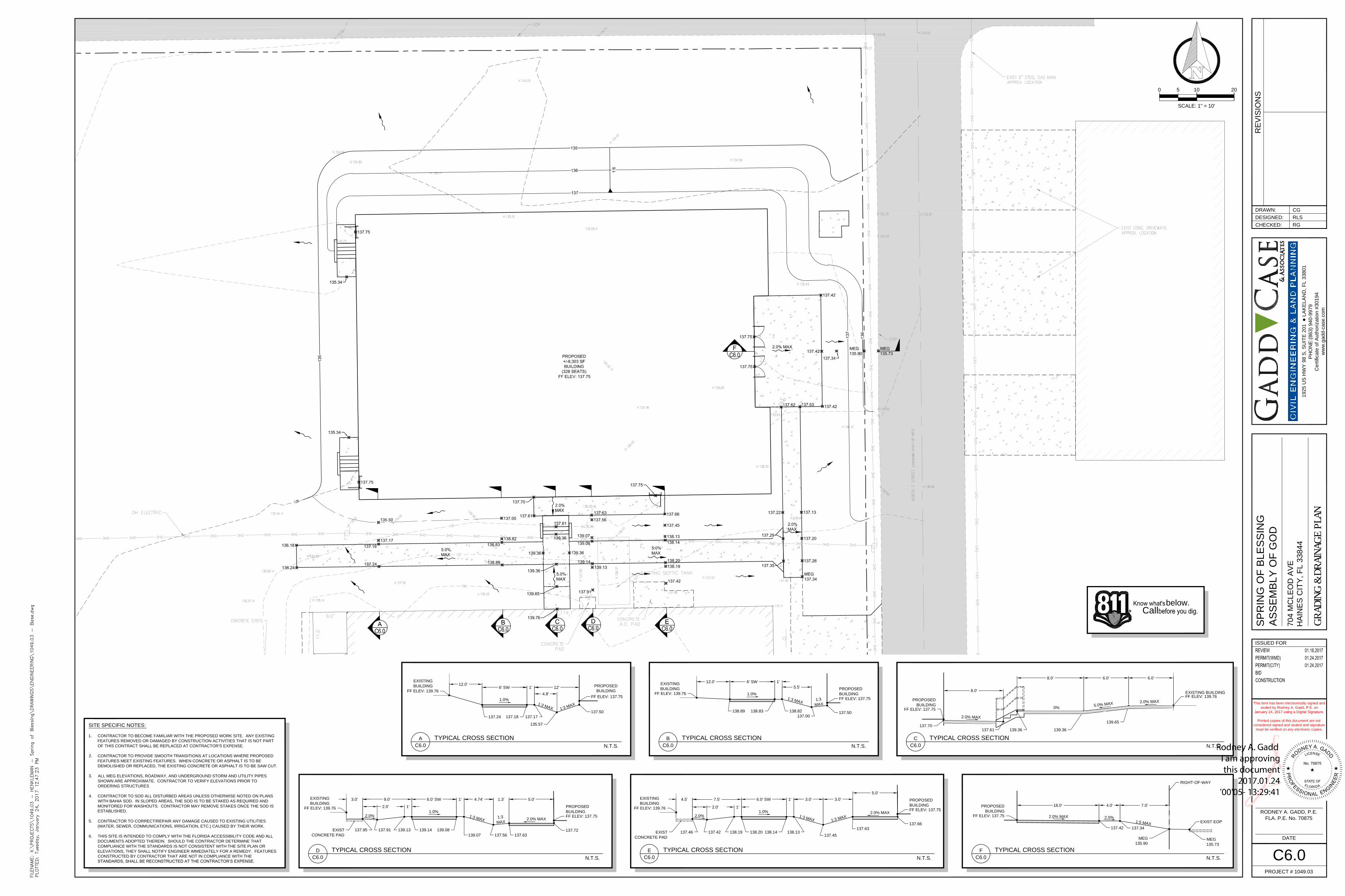
C6.0
GRAD
ING
& DR
AINA
GE P
LAN
below.
Call
R
SITE SPECIFIC NOTES:
1. CONTRACTOR TO BECOME FAMILIAR WITH THE PROPOSED WORK SITE. ANY EXISTING
FEATURES REMOVED OR DAMAGED BY CONSTRUCTION ACTIVITIES THAT IS NOT PART
OF THIS CONTRACT SHALL BE REPLACED AT CONTRACTOR'S EXPENSE.
2. CONTRACTOR TO PROVIDE SMOOTH TRANSITIONS AT LOCATIONS WHERE PROPOSED
FEATURES MEET EXISTING FEATURES. WHEN CONCRETE OR ASPHALT IS TO BE
DEMOLISHED OR REPLACED, THE EXISTING CONCRETE OR ASPHALT IS TO BE SAW CUT.
3. ALL MEG ELEVATIONS, ROADWAY, AND UNDERGROUND STORM AND UTILITY PIPES
SHOWN ARE APPROXIMATE. CONTRACTOR TO VERIFY ELEVATIONS PRIOR TO
ORDERING STRUCTURES
4. CONTRACTOR TO SOD ALL DISTURBED AREAS UNLESS OTHERWISE NOTED ON PLANS
WITH BAHIA SOD. IN SLOPED AREAS, THE SOD IS TO BE STAKED AS REQUIRED AND
MONITORED FOR WASHOUTS. CONTRACTOR MAY REMOVE STAKES ONCE THE SOD IS
ESTABLISHED.
5. CONTRACTOR TO CORRECT/REPAIR ANY DAMAGE CAUSED TO EXISTING UTILITIES
(WATER, SEWER, COMMUNICATIONS, IRRIGATION, ETC.) CAUSED BY THEIR WORK.
6. THIS SITE IS INTENDED TO COMPLY WITH THE FLORIDA ACCESSIBILITY CODE AND ALL
DOCUMENTS ADOPTED THEREIN. SHOULD THE CONTRACTOR DETERMINE THAT
COMPLIANCE WITH THE STANDARDS IS NOT CONSISTENT WITH THE SITE PLAN OR
ELEVATIONS, THEY SHALL NOTIFY ENGINEER IMMEDIATELY FOR A REMEDY. FEATURES
CONSTRUCTED BY CONTRACTOR THAT ARE NOT IN COMPLIANCE WITH THE
STANDARDS, SHALL BE RECONSTRUCTED AT THE CONTRACTOR’S EXPENSE.
6.0'
137.70
8.0'
6.0'8.0'
139.36
139.65
FF ELEV: 139.76
C
C6.0
TYPICAL CROSS SECTION
N.T.S.
139.36137.61
PROPOSED
BUILDING
EXISTING BUILDING
1.0%
6' SW 1'
1
:
3
M
A
X
137.24 137.17
135.57
137.50
12'
A
C6.0
TYPICAL CROSS SECTION
N.T.S.
PROPOSED
BUILDING
1.0%
6' SW 1'
1
:3
M
A
X
138.89 138.82
137.00
B
C6.0
TYPICAL CROSS SECTION
N.T.S.
PROPOSED
BUILDING
5.5'
4.8'
1
:
3
M
A
X
FF ELEV: 137.75
EXISTING
BUILDING
FF ELEV: 139.76
137.50
EXISTING
BUILDING
FF ELEV: 139.76
138.83
FF ELEV: 137.75
1:3
M
AX
2.0% MAX
0%
5.0
%
M
AX
2.0% MAX
FF ELEV: 137.75
1.0%
139.14
6.0' SW 1'
1
:3
M
A
X
139.07 137.56
D
C6.0
TYPICAL CROSS SECTION
N.T.S.
PROPOSED
BUILDING
139.08
4.74'
137.72
EXISTING
BUILDING
FF ELEV: 139.76
9.0'
FF ELEV: 137.75
1:3
M
AX
12.0'
137.95EXIST
CONCRETE PAD
2.0% MAX
137.63
1.3' 5.0' 4.5'
1.0%
6.0' SW 1'
1
:3
M
A
X
138.13
137.45
E
C6.0
TYPICAL CROSS SECTION
N.T.S.
PROPOSED
BUILDING
3.0'
EXISTING
BUILDING
FF ELEV: 139.76
138.14
FF ELEV: 137.75
137.66
7.5'
137.46 138.20EXIST
CONCRETE PAD
2.0% MAX
137.63
3.0'
5.0'
1
:3
M
A
X
F
C6.0
TYPICAL CROSS SECTION
N.T.S.
PROPOSED
BUILDING
FF ELEV: 137.75
2.0% MAX
18.0' 4.0'
2.0%
1:5 M
A
X
137.42137.34
MEG
135.90
7.0'
EXIST EOP
MEG
135.73
RIGHT-OF-WAY
137.91
2.0'
2.0%
137.18
1'
139.13
2.0'
2.0%
1'
138.19137.42
12.0'