Embed Size (px)
Citation preview
ARTICLE IN PRESS
Contents lists available at ScienceDirect
Journal of Sound and Vibration
Journal of Sound and Vibration 325 (2009) 781–797
0022-46
doi:10.1
� Cor
E-m
journal homepage: www.elsevier.com/locate/jsvi
Vibrations of porous piezoelectric ceramic plates
Anil K. Vashishth �, Vishakha Gupta
Department of Mathematics, Kurukshetra University, Kurukshetra 136119, India
a r t i c l e i n f o
Article history:
Received 17 June 2008
Received in revised form
16 March 2009
Accepted 21 March 2009
Handling Editor: L.G. Thamresults are obtained in particular for monoclinic (2) porous piezoelectric materials.
Available online 29 April 2009
0X/$ - see front matter & 2009 Published by
016/j.jsv.2009.03.034
responding author.
ail address: [email protected] (A.K.
a b s t r a c t
The basic constitutive equations and equations of motion are derived for anisotropic
porous piezoelectric materials by making use of variational principle. These equations
are first derived for three-dimensional case and then reduced to the two-dimensional
case by expanding mechanical displacement and electric potential as power series. The
Thickness shear correction factors are determined for high frequency case. The thickness
shear resonance frequencies are obtained numerically for a particular model of PZT.
& 2009 Published by Elsevier Ltd.
0. Introduction
It is well known that piezoelectric materials produce an electric field when deformed and undergo deformation whensubjected to an electric field. Piezoelectric materials are integrated with structural systems to form a class of smartstructures. Piezoelectric materials have wide-spread applications in many areas such as electronic technology, mechanicalengineering, medical appliance and other modern industrial fields. During few recent decades, piezoelectric materials havebeen intensively used as transducers, actuators, sensors etc. Piezoelectric materials and components are always fabricatedin plates or shell configuration for engineering use. The constitutive equations for piezoelectric crystals of different kinds ofanisotropy were described by Cady [1]. The characteristics of different piezoelectric materials are described in the textMason [2]. These equations are also described in the text Holland and Nisse [3]. Based on an approximation involving theearly terms of the thickness coordinate of plate, the classical equations of piezoelectricity were reduced from three to twodimensions by Mindlin [4]. Only flexure, thickness-shear and thickness-twist modes were taken into account. Later on, theequations were extended to include the face-extension and face-shear modes by Tiersten and Mindlin [5]. A detailed texton vibrations of linear piezoelectric plates was presented by Tiersten [6]. The two-dimensional equations of motion werederived by Mindlin [7] using expansion of mechanical displacement and electrical potential as power series. The thickness-shear correction factors were also determined.
Shear horizontal vibration modes of plates are often used for bulk acoustic wave piezoelectric resonators and otherdevices [8]. Shaw [9] discovered the edge modes in piezoelectric finite cylindrical disks with edge conditions in addition tothe boundary conditions. He investigated the thickness, shear and radial vibrations of thick barium titanate disk by opticalinterference methods in wide range of thickness/radius ratio. Some studies [10–13] on thickness-shear and flexurevibrations of plates have also been made by different authors. A new theory for electroded piezoelectric plates and its finiteelement applications for the forced vibrations of quartz crystal resonators were presented [14]. The general vibrationproblem of a spherically isotropic piezoelectric medium with radial inhomogeneity was studied by Chen [15] usingseparation method. The nature of coupling field was investigated for some cases of longitudinal waves propagating in thin,infinitely long, piezoceramics rods with their axes parallel to poling axis [16]. Piquette [17] obtained the couplingcoefficients for electrostrictive ceramics. Yang [18] obtained an exact solution for shear horizontal vibrations of a
Elsevier Ltd.
Vashishth).
ARTICLE IN PRESS
A.K. Vashishth, V. Gupta / Journal of Sound and Vibration 325 (2009) 781–797782
piezoelectric wedge of polarized ceramics. The steady-state vibrations of an infinite piezoelectric medium withtransversely isotropic symmetry were studied by Lioubimova and Schiavone [19], by considering fundamental boundaryvalue problems in a theory of generalized plane strain.
Free vibration occurs when a mechanical system is set off with an initial input and then allowed to vibrate freely.A uniformizing method [20] was presented for free vibration analysis of metal–piezoceramics composite thin plates withdifferent shapes, vibration modes and boundary conditions. In Refs. [21,22], the free vibrations of piezoelectric circularplates, by employing the general solution for coupled three-dimensional equations of transversely isotropic piezoelectricbody were investigated. Based on newly presented state space formulations, a method [23] was developed for analyzingthe bending, vibrations and stability of laminated transversely isotropic rectangular plates with simply supported edges. Ananalytical solution was obtained for free vibrations of piezoelectric annular plates by using general solutions for coupledthree-dimensional equations of piezoelectric media [24]. The resonant electromechanical vibrations of thin piezoelectricplates under elastic loading were studied by Karlash [25].
The concepts of functionally grade materials (FGM) have been applied to piezoelectric materials to improve its lifetimeand reliability of advanced piezoelectric structures. Different authors [26,27] have addressed the problems related to thefree vibrations of such functionally grade materials.
Piezoelectric layers are embedded in or surface bonded on isotropic or laminated composite structures to form (smart)structures. Such structures are defined as ‘‘piezoelectric composite laminates’’. Vibration characteristics of piezoelectriccomposite materials are of interest in the field of Science and Engineering. A lot of work has been done in the field. Mentiona few [28–35], in which number of problems related to vibrations of laminated piezoelectric composite materials, havebeen investigated.
A set of equations of high frequency vibrations of piezothermoelastic crystal plate was obtained by Mindlin [36]. Three-dimensional solutions for free vibrations of initially stressed thermoelectroelastic multilayered plates have been obtainedin Ref. [37]. The nonlinear vibration behavior of piezoelectric materials was observed in Refs. [38–40].
Despite the significant progress made in enhancing the coupling characteristics between electrical and mechanicalproperties in piezoelectric materials, monolithic piezoelectric materials generally exhibit limitation such as brittleness. Dueto brittleness nature of piezoelectric ceramics and possible defects of impurity, cavities and microcracks, failure of devicestake place easily under mechanical or electrical loading. In order to overcome this limitation, material density is reducedthrough the addition of controlled porosity and resulting porous piezoelectric materials (PPM) are widely used forapplications such as low frequency hydrophones, miniature, accelerometers, vibratory sensors and contact microphones.Due to lower acoustic impedance, these materials can be used to improve mismatch of acoustic impedances at theinterfaces of medical ultrasonic imaging devices or underwater sonar detectors. Several piezoceramic constructiveelements are porous especially when they are hot pressured or cast under pressure. Use of the piezoelectric effect in porouspiezoelectric ceramics offers an original method for studying the coupling between electrical, mechanical, permeabilityand of course piezoelectric properties of porous systems. Khoroshun et al. [41,42] presented a general approach, tocalculate the effective electroelastic properties of polycrystals with spheroidal crystallites, based on conditional averagingof the electroelasticity equations. Khoroshun and Dorodnykh [43,44] evaluated the effective electroelastic properties ofporous polycrystals with trigonal symmetry and observed that all the effective constants depend considerably on both theconcentration and shapes of the pores. Similar results were also obtained by Gupta and Venkatesh [45] by using a finiteelement model for porous piezoelectric ceramics. A survey of literature reveals that while a lot of work has been done onvibration analysis of piezoelectric material, piezothermoelastic materials and other smart materials, but no work has beendone on vibration analysis of porous piezoelectric materials so far.
In this paper, an attempt is made to formulate the equations of the vibration of unclamped porous piezoelectric crystalplates. In Section 1, using Biot’s theory and electrical enthalpy density function, we first derive basic constitutive equationsfor anisotropic porous piezoelectric materials and then equations of motion for PPM are derived using variational principle.In Section 2, the constitutive relations and equation of motion are obtained for two-dimensional case by expandingmechanical displacement and electrical potential function as power series. In Section 3, particular cases of constitutiverelations are obtained with approximation of series after truncation and adjustment of some terms. Further expressions aremodified by introducing thickness-shear correction factors. The results are obtained in particular for high frequencyvibrations. The thickness-shear correction factors are determined for the Monoclinic (2) crystal by comparing thickness-shear frequencies corresponding to the two- and three-dimensional case in Section 4. Finally, in Section 5, the thicknessshear resonance frequencies are obtained numerically for a particular model of PZT and variation of resonance frequency inthickness shear mode with the thickness of the plate is observed. The effect of thickness of plate on the three-dimensionalthickness shear resonance frequency for first five modes is also observed.
1. Three-dimensional equation
1.1. Constitutive equations
Let us consider a porous piezoelectric body having a volume V bounded by a surface S with unit outward normal n. Letsij; �ij;s�; �� be stress and strain components for solids; fluid phase of porous aggregate, respectively. The quantities with *
ARTICLE IN PRESS
A.K. Vashishth, V. Gupta / Journal of Sound and Vibration 325 (2009) 781–797 783
are associated to the fluid component of porous bulk material. Let Ei;Di;E�i ;D�i be electric field and electric displacement of
solid; fluid phase, respectively.The electric enthalpy density function (W) for porous piezoelectric material is defined as
W ¼ 12½sij�ij þ s��� � EiDi � E�i D�i � (1)
This enthalpy density function W is a quadratic function of �ij; ��; Ei and E�i .
W ¼ 12cijkl�ij�kl þ
12R���� þmij�ij�
� � ekijEk�ij � zkijE�k�ij �
~ziEi�� � e�i E�i �
�
� 12xijEiEj �
12x�ijE�i E�j � AijEiE
�j , (2)
where coefficients cijkl; ekij; zkij;mij; xij; x�ij;Aij; e
�i ;~zi and R are tensors of order 4; 3; 2; 1 and zero, respectively.
�ij ¼12ðui;j þ uj;iÞ; �� ¼ U�k;k; Ei ¼ �f;i; E�i ¼ �f
�;i, (3)
where ui;f;U�i ;f� are mechanical displacements and electric potential for solid; fluid phase, respectively.
Eq. (2) gives us
qW
q�ij¼ cijkl�kl þmij�
� � ekijEk � zkijE�k, (4a)
qW
q��¼ R�� þmij�ij �
~ziEi � e�i E�i , (4b)
qW
qEk¼ �ekij�ij �
~zk�� � xkjEj � AkjE
�j , (4c)
qW
qE�k¼ �zkij�ij � e�k�
� � AjkEj � x�kjE�j . (4d)
It is known from the definition of the electric enthalpy density function that
qW
q�ij¼ sij;
qW
q��¼ s�; qW
qEi¼ �Di;
qW
qE�i¼ �D�i . (5)
This implies that
sij ¼ cijkl�kl þmij�� � ekijEk � zkijE
�k, (6a)
s� ¼ mij�ij þ R�� � ~ziEi � e�i E�i , (6b)
Di ¼ eijk�jk þ~zi�� þ xijEj þ AijE
�j , (6c)
D�i ¼ zijk�jk þ e�i �� þ AijEj þ x�ijE
�j . (6d)
These are constitutive equations for anisotropic porous piezoelectric materials. Here cijkl are elastic stiffness constants. The
elastic constant R measures the pressure to be exerted on fluid to push its unit volume into the porous matrix. ekij; xij; e�i ; x�ij
are piezoelectric and dielectric constant for solid; fluid phase, respectively. mij; zkij;~zi;Aij are the parameters which take
into account the elastic; piezoelectric; dielectric coupling between the two phases of porous aggregate.
1.2. Equations of motion
Using variational principle, we can write
dZ t1
t0
dt
ZVðK �WÞdV þ
Z t1
t0
dt
ZSðtjduj þ t�j dU�j þ cdjþ c�dj�ÞdS
" #¼ 0, (7)
where tj; t�j are surface traction for solid and fluid phase of porous bulk material. K is the kinetic energy density. c; c� are
surface charge density for solid and fluid phase.The kinetic energy density K is defined as
K ¼ 12fr11 _ui _ui þ 2r12 _ui
_U�
i þ r22_U�
i_U�
i g, (8)
where r11;r12 and r22 are the dynamical coefficients which depend upon the porosity (f), density of porous aggregate (r),pore fluid density (rf) and the inertial coupling parameters.
ARTICLE IN PRESS
A.K. Vashishth, V. Gupta / Journal of Sound and Vibration 325 (2009) 781–797784
Eq. (8) implies
dZ t1
t0
K dt ¼ � r11
Z t1
t0
€uidui dt þ r22
Z t1
t0
€U�
i dU�i dt þ r12
Z t1
t0
ð €uidU�i þ€U�
i duiÞdt
" #. (9)
Also
dZ
VW dV ¼
ZV
qW
q�ijd�ij þ
qW
q��d�� þ
qW
qEidEi þ
qW
qE�idE�i
!dV
¼
ZSðsijduj þ s�dU�i þ Didjþ D�i dj
�Þni dS�
ZVðsij;iduj þ s�;idU�i þ Di;idjþ D�i;idj
�ÞdV . (10)
Making use of Eqs. (9) and (10), Eq. (7) can be written asZ t1
t0
dt
ZV½ðsij;i � r11 €uj � r12
€U�
j Þduj þ ðs�;i � r22€U�
i � r12 €uiÞdU�i þ Di;idjþ D�i;idj��dV
þ
Z t1
t0
dt
ZS½ðtj � sijniÞduj þ ðt
�i � s
�niÞdU�i þ ðc � DiniÞdjþ ðc� � D�i niÞdj��dS ¼ 0.
)In V,
sij;i ¼ r11 €uj þ r12€U�
j , (11a)
s�;i ¼ r12 €ui þ r22€U�
i , (11b)
Di;i ¼ 0, (11c)
D�i;i ¼ 0. (11d)
With boundary conditions specified on the surface S as
sijni ¼ tj, (12a)
s�ni ¼ t�i , (12b)
Dini ¼ c, (12c)
D�i ni ¼ c�. (12d)
Eqs. (11a) and (11b) are equations of motion for porous piezoelectric materials when body forces are absent. Eqs. (11c) and(11d) correspond to Gauss equation.
2. Two-dimensional equations
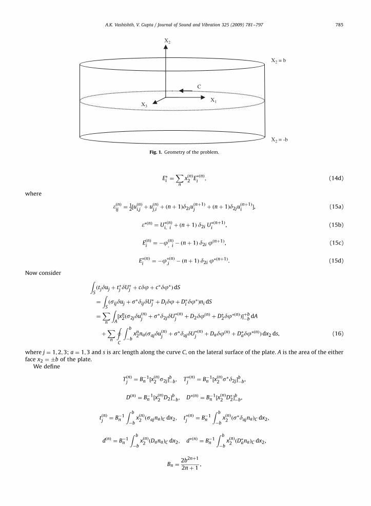
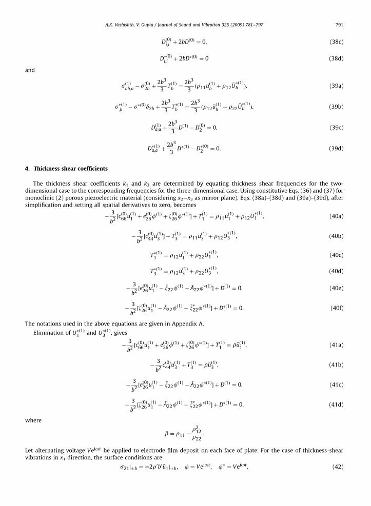
Let us consider a plate of thickness 2b, with Cartesian coordinate axes x1; x3 in the middle plane and x2 normal to theplate (Fig. 1). Let the two-dimensional region in the x1 � x3 plane occupied by piezoelectric plate be A, the boundary curveof A be C, the unit outward normal to the curve C be ni.
Let mechanical displacement and electrical potential can be expressed as power series in x2:
ui ¼X
n
xn2uðnÞ
i; U�i ¼
Xn
xn2U�ðnÞ
i,
j ¼X
n
xn2jðnÞ; j� ¼
Xn
xn2j�ðnÞ ði ¼ 1;2;3; n ¼ 0; . . . ;1Þ, (13)
where uðnÞi;U�ðnÞ
i;jðnÞ;j�ðnÞ are functions of x1; x3 and t.
Now
�ij ¼1
2ðui;j þ uj;iÞ ¼
Xn
xn2�ðnÞij
. (14a)
Similarly, we can write
�� ¼X
n
xðnÞ2 ��ðnÞ, (14b)
Ei ¼X
n
xðnÞ2 EðnÞi
, (14c)
ARTICLE IN PRESS
X1X3
X2
X2 = -b
X2 = b
C
Fig. 1. Geometry of the problem.
A.K. Vashishth, V. Gupta / Journal of Sound and Vibration 325 (2009) 781–797 785
E�i ¼X
n
xðnÞ2 E�ðnÞi
; (14d)
where
�ðnÞij¼ 1
2½uðnÞi;jþ uðnÞ
j;iþ ðnþ 1Þd2iu
ðnþ1Þj
þ ðnþ 1Þd2juðnþ1Þi�, (15a)
��ðnÞ ¼ U�ðnÞi; iþ ðnþ 1Þ d2i U�ðnþ1Þ
i, (15b)
EðnÞi¼ �jðnÞ
; i� ðnþ 1Þ d2i jðnþ1Þ, (15c)
E�ðnÞi¼ �j�ðnÞ
;i� ðnþ 1Þ d2i j�ðnþ1Þ. (15d)
Now consider ZSðtjduj þ t�j dU�j þ cdjþ c�dj�ÞdS
¼
ZSðsijduj þ s�dijdU�j þ Didjþ D�i dj
�Þni dS
¼X
n
ZA½xn
2ðs2jduðnÞjþ s�d2jdU�ðnÞ
jþ D2djðnÞ þ D�2dj
�ðnÞÞ�þb�b
dA
þX
n
IC
Z b
�bxn
2naðsajduðnÞjþ s�dajdU�ðnÞ
jþ DadjðnÞ þ D�adj
�ðnÞÞdx2 ds, (16)
where j ¼ 1;2;3; a ¼ 1;3 and s is arc length along the curve C, on the lateral surface of the plate. A is the area of the eitherface x2 ¼ �b of the plate.
We define
TðnÞj¼ B�1
n ½xðnÞ2 s2j�
b�b; T�ðnÞ
j¼ B�1
n ½xðnÞ2 s�d2j�
b�b,
DðnÞ ¼ B�1n ½x
ðnÞ2 D2�
b�b; D�ðnÞ ¼ B�1
n ½xðnÞ2 D�2�
b�b,
tðnÞj¼ B�1
n
Z b
�bxðnÞ2 ðsajnaÞC dx2; t�ðnÞ
j¼ B�1
n
Z b
�bxðnÞ2 ðs
�dajnaÞC dx2,
dðnÞ ¼ B�1n
Z b
�bxðnÞ2 ðDanaÞC dx2; d�ðnÞ ¼ B�1
n
Z b
�bxðnÞ2 ðD
�anaÞC dx2,
Bn ¼2b2nþ1
2nþ 1,
ARTICLE IN PRESS
A.K. Vashishth, V. Gupta / Journal of Sound and Vibration 325 (2009) 781–797786
K ¼
Z b
�bK dx2; W ¼
Z b
�bW dx2. (17)
‘Z
Sðtjduj þ t�j dU�j þ cdjþ c�dj�ÞdS
¼X
n
ZA½BnTðnÞ
jduðnÞ
jþ BnT�ðnÞ
jdU�ðnÞ
jþ BnDðnÞdjðnÞ þ BnD�ðnÞdj�ðnÞ�dA
þX
n
IC
½BntðnÞjduðnÞ
jþ Bnt�ðnÞ
jdU�ðnÞ
jþ BndðnÞdjðnÞ þ Bnd�ðnÞdj�ðnÞ�ds:
Using the above equation, Eq. (7) for two-dimensional case can now be written as
dZ t1
t0
dt
ZAðK � WÞdAþ
Z t1
t0
dt
ZA
Xn
BnðTðnÞjduðnÞ
jþ T�ðnÞ
jdU�ðnÞ
jþ DðnÞdjðnÞ þ D�ðnÞdj�ðnÞÞdA
"
þ
Z t1
t0
dt
IC
Xn
BnðtðnÞjduðnÞ
jþ t�ðnÞ
jdU�ðnÞ
jþ dðnÞdjðnÞ þ d�ðnÞdj�ðnÞÞds
375 ¼ 0. (18)
Here,
K ¼1
2
Z b
�b
Xm
Xn
ðr11 _uðmÞi
_uðnÞiþ 2r12 _u
ðmÞi
_U�ðnÞi þ r22
_U�ðmÞi
_U�ðnÞi Þ
" #dx2
) dZ t1
t0
K dt ¼ � r11
Z t1
t0
Xm
Xn
Bmn €uðmÞi
duðnÞiþ r22
Z t1
t0
Xm
Xn
Bmn_U�ðmÞi dU�ðnÞ
i
"
þ r12
Z t1
t0
Xm
Xn
Bmnð €uðmÞi
dU�ðnÞiþ €U�ðnÞi duðmÞ
iÞ
#, (19)
where
Bmn ¼
Z b
�bxmþn
2 dx2 ¼
2bmþnþ1
mþ nþ 1when mþ n is even
0 when mþ n is odd
8><>: ,
and
dW ¼
Z b
�bdW dx2 ¼
Xn
ðsðnÞijd�ðnÞ
ijþ s�ðnÞd��ðnÞ � DðnÞ
idEðnÞ
i� D�ðnÞ
idE�ðnÞ
iÞdx2
¼X
n
½sðnÞijduðnÞ
jþ s�ðnÞdijdU�ðnÞ
jþ DðnÞ
idjðnÞ þ D�ðnÞ
idj�ðnÞ�;i
þX
n
½ðnsðn�1Þ2j
� sðnÞij;iÞduðnÞ
jþ ðns�ðn�1Þd2j � s
�ðnÞ;jÞdU�ðnÞ
j
þ ðnDðn�1Þ2 � DðnÞ
i;iÞdjðnÞ þ ðnD�ðn�1Þ
2 � D�ðnÞi;iÞdj�ðnÞ�,
where
sðnÞij¼
Z b
�bsijxðnÞ2 dx2; s�ðnÞ ¼
Z b
�bs�xðnÞ2 dx2; DðnÞ
i¼
Z b
�bDixðnÞ2 dx2; D�ðnÞ
i¼
Z b
�bD�i xðnÞ2 dx2. (20)
‘Z
AdW dA ¼
ZA
Xn
½ðnsðn�1Þ2j
� sðnÞij;iÞduðnÞ
jþ ðns�ðn�1Þd2j � s
�ðnÞ;jÞdU�ðnÞ
j
þ ðnDðn�1Þ2 � DðnÞ
i;iÞdjðnÞ þ ðnD�ðn�1Þ
2 � D�ðnÞi;iÞdj�ðnÞ�dA
þ
IC
Xn
½sðnÞajduðnÞ
jþ sðnÞdajdU�ðnÞ
jþ DðnÞa djðnÞ þ D�ðnÞa dj�ðnÞ�na ds: (21)
ARTICLE IN PRESS
A.K. Vashishth, V. Gupta / Journal of Sound and Vibration 325 (2009) 781–797 787
Using Eqs. (19) and (21) in Eq. (18), we get
Xn
Z t1
t0
dt
ZAsðnÞ
ij;i� nsðn�1Þ
2j�Xm
r11Bmn €uðmÞj�Xm
r12Bmn€U�ðmÞj þ BnTðnÞ
j
" #duðnÞ
jdA
þX
n
Z t1
t0
dt
ZAs�ðnÞ;j� nd2js�ðn�1Þ �
Xm
r12Bmn €uðmÞj�Xm
r22Bmn€U�ðmÞj þ BnT�ðnÞ
j
" #dU�ðnÞ
jdA
þX
n
Z t1
t0
dt
ZAðDðnÞ
i;i� nDðn�1Þ
2 þ BnDðnÞÞdjðnÞ dA
þX
n
Z t1
t0
dt
ZAðD�ðnÞ
i;i� nD�ðn�1Þ
2 þ BnD�ðnÞÞdj�ðnÞ dA
þX
n
Z t1
t0
dt
IC½ðBntðnÞ
j� sðnÞ
ajnaÞduðnÞ
jþ ðBnT�ðnÞ
j� s�ðnÞdajnaÞdU�ðnÞ
j
þ ðBndðnÞ � DðnÞa naÞdjðnÞ þ ðBnd�ðnÞ � D�ðnÞa naÞdj�ðnÞ�ds ¼ 0.
) In A; sðnÞij;i� nsðn�1Þ
2jþ BnTðnÞ
j¼Xm
Bmnðr11 €uðmÞjþ r12
€U�ðmÞj Þ, (22a)
s�ðnÞ;j� ns�ðn�1Þd2j þ BnT�ðnÞ
j¼Xm
Bmnðr12 €uðmÞjþ r22
€U�ðmÞj Þ; (22b)
DðnÞi;i� nDðn�1Þ
2 þ BnDðnÞ ¼ 0, (22c)
DðnÞi;i� nD�ðn�1Þ
2 þ BnD�ðnÞ ¼ 0. (22d)
With boundary conditions on the curve C,
BntðnÞj� sðnÞ
ajna ¼ 0, (23a)
Bnt�ðnÞj� s�ðnÞdajna ¼ 0, (23b)
BndðnÞ � DðnÞa na ¼ 0, (23c)
Bnd�ðnÞ � D�ðnÞa na ¼ 0 (23d)
The constitutive equations of order n are
sðnÞij¼
Z b
�bxðnÞ2 sij dx2 ¼
Z b
�b
Xm
xn2xm
2 ðcijkl�ðmÞklþmij�
�ðmÞ � ekijEðmÞk� zkijE
�ðmÞkÞdx2.
Since �ðmÞkl
, ��ðmÞ, EðmÞk
, E�ðmÞk
are independent of x2, therefore above integral can be written as
sðnÞij¼Xm
Bmnðcijkl�ðmÞklþmij�
�ðmÞ � ekijEðmÞk� zkijE
�ðmÞkÞ. (24a)
Similarly, other constitutive equations can be written as
s�ðnÞ ¼Xm
Bmnðmij�ðmÞijþ R��ðmÞ � ~ziE
ðmÞi� e�i E�ðmÞ
iÞ, (24b)
DðnÞi¼Xm
Bmnðeijk�ðmÞjkþ ~zi�
�ðmÞ þ xijEðmÞjþ AijE
�ðmÞjÞ; (24c)
D�ðnÞi¼Xm
Bmnðzijk�ðmÞjkþ e�i �
�ðmÞ þ AijEðmÞjþ x�ijE
�ðmÞjÞ: (24d)
3. Truncation of series and adjustments
After truncation of terms of order higher than 1, Eqs. (24a)–(24d) for the cases n ¼ 0 and 1 can now be written as
sð0Þij¼ 2bðcijkl�
ð0Þklþmij�
�ð0Þ � ekijEð0Þk� zkijE
�ð0ÞkÞ, (25a)
ARTICLE IN PRESS
A.K. Vashishth, V. Gupta / Journal of Sound and Vibration 325 (2009) 781–797788
s�ð0Þ ¼ 2bðmij�ð0Þijþ R��ð0Þ � ~ziE
ð0Þi� e�i E�ð0Þ
iÞ, (25b)
Dð0Þi¼ 2bðeijk�
ð0Þjkþ ~zi�
�ð0Þ þ xijEð0Þjþ AijE
�ð0ÞjÞ, (25c)
D�ð0Þi¼ 2bðzijk�
ð0Þjkþ e�i �
�ð0Þ þ AijEð0Þjþ x�ijE
�ð0ÞjÞ (25d)
and
sð1Þij¼
2b3
3ðcijkl�
ð1Þklþmij�
�ð1Þ � ekijEð1Þk� zkijE
�ð1ÞkÞ, (26a)
s�ð1Þ ¼ 2b3
3ðmij�
ð1Þijþ R��ð1Þ � ~ziE
ð1Þi� e�i E�ð1Þ
iÞ, (26b)
Dð1Þi¼
2b3
3ðeijk�
ð1Þjkþ ~zi�
�ð1Þ þ xijEð1Þjþ AijE
�ð1ÞjÞ, (26c)
D�ð1Þi¼
2b3
3ðzijk�
ð1Þjkþ e�i �
�ð1Þ þ AijEð1Þjþ x�ijE
�ð1ÞjÞ (26d)
The kinetic energy density K after truncation of terms of order higher than 1 is
K ¼ bðr11 _uð0Þi_uð0Þ
iþ 2r12 _u
ð0Þi_U�ð0Þi þ r22
_U�ð0Þi
_U�ð0Þi Þ
þb3
3ðr11 _u
ð1Þi_uð1Þ
iþ 2r12 _u
ð1Þi_U�ð1Þi þ r22
_U�ð1Þi
_U�ð1Þi Þ. (27)
Following Cauchy [46], we neglect the velocity _uð1Þ2 , _Uð1Þ2 in kinetic energy density and free development of strain �ð0Þ22 is
obtained by setting sð0Þ22 ¼ 0 in (25a) i.e.
�ð0Þ22 ¼�c22kl
c2222�ð0Þ
kl�
m22
c2222��ð0Þ þ
ek22
c2222Eð0Þ
kþ
zk22
c2222E�ð0Þ
kþ �ð0Þ22 . (28)
) ð2bÞ�1sð0Þij¼ ðcijkl�
ð0Þkl� cij22�
ð0Þ22 Þ þ cij22�
ð0Þ22 þmij�
�ð0Þ � ekijEð0Þk� zkijE
�ð0Þk
.
Using Eq. (28), above equation reduces to
sð0Þij¼ 2bðcijkl�
ð0Þklþ mij�
�ð0Þ � ekijEð0Þk� zkijE
�ð0ÞkÞ, (29a)
where
cijkl ¼ cijkl �cij22c22kl
c2222; mij ¼ mij �
cij22m22
c2222; ekij ¼ ekij �
cij22ek22
c2222; zkij ¼ zkij �
cij22zk22
c2222.
By following same procedure of elimination, the expressions for s�ð0Þ;Dð0Þi;D�ð0Þ
ican be obtained as
s�ð0Þ ¼ 2bðmij�ð0Þijþ R��ð0Þ � ~ziE
ð0Þi� e�i E�ð0Þ
iÞ, (29b)
Dð0Þi¼ 2bðeijk�
ð0Þjkþ ~zi�
�ð0Þ þ xijEð0Þjþ AijE
�ð0ÞjÞ, (29c)
D�ð0Þi¼ 2bðzijk�
ð0Þjkþ e�i �
�ð0Þ þ AijEð0Þjþ x�ijE
�ð0ÞjÞ, (29d)
where
xij ¼ xij þei22ej22
c2222; x�ij ¼ x�ij þ
zi22zj22
c2222,
Aij ¼ Aij þei22zj22
c2222; R ¼ R�
m22m22
c2222,
e�i ¼ e�i �m22zi22
c2222; ~zi ¼
~zi �m22ei22
c2222.
ARTICLE IN PRESS
A.K. Vashishth, V. Gupta / Journal of Sound and Vibration 325 (2009) 781–797 789
In the first-order terms, we neglect the velocity _uð2Þj
, _Uð2Þj in kinetic energy density and free development of strains �ð1Þ
2jis
obtained by setting sð1Þ2j¼ 0 in Eq. (26a) which gives
sijmnsð1Þij¼
2b3
3ðsijmncijkl�
ð1Þklþ sijmnmij�
�ð1Þ � sijmnekijEð1Þk� sijmnzkijE
�ð1ÞkÞ, (30)
where sijmn is the compliance tensor. We define
Imnkl ¼ cijklsijmn; mImn ¼ sijmnmij; eI
kmn ¼ sijmnekij; zIkmn ¼ sijmnzkij,
sijmnsð1Þij¼
2b3
3ð�ð1Þmn þmI
mn��ð1Þ � eI
kmnEð1Þk� zI
kmnE�ð1ÞkÞ.
By setting sð1Þ2j¼ 0 in the above equation, we get
sabcdsð1Þcd¼
2b3
3ð�ð1Þ
abþmI
ab��ð1Þ � eI
cabEð1Þc � zIcabE�ð1Þc Þ ða; b; c; d ¼ 1 and 3Þ.
Solving this system of equations forsð1Þ11, sð1Þ13 , sð1Þ33 , we obtain
sð1Þab¼
2b3Aabcd
3jsabcdjð�ð1Þ
cdþmI
cd��ð1Þ � eI
ecdEð1Þe � zIecdE�ð1Þe Þ,
where
jsabcdj ¼
s1111 s3311 s1311
s1133 s3333 s1333
s1113 s3313 s1313
��������������,
and Aabcd is corresponding cofactor of element sabcd in ½sabcd�.
‘sð1Þab¼
2b3
3ðcð1Þ
abcd�ð1Þ
cdþmð1Þ
ab��ð1Þ � eð1Þ
cabEð1Þc � zð1Þ
cabE�ð1Þc Þ, (31)
where
cð1Þabcd¼
Aabcd
jsabcdj; mð1Þ
ab¼ cð1Þ
abcdmI
cd; eð1Þeab¼ c1
abcdeIecd; zð1Þ
eab¼ c1
abcdzIecd.
The electric enthalpy density function W from which relations (29a) and (31) are obtained, can now be written as
W ¼ b½cijkl�ð0Þij�ð0Þ
klþ 2mij�
ð0Þij��ð0Þ þ R��ð0Þ��ð0Þ � 2ekij�
ð0Þij
Eð0Þk� 2zkij�
ð0Þij
E�ð0Þk
� 2 ~ziEð0Þi��ð0Þ � 2e�i E�ð0Þ
i��ð0Þ � xijE
ð0Þi
Eð0Þj� x�ijE
�ð0Þi
E�ð0Þj� 2AijE
ð0Þi
E�ð0Þj�
þb3
3½cð1Þ
abcd�ð1Þ
ab�ð1Þ
cdþ 2mð1Þ
ab�ð1Þ
ab��ð1Þ þ R��ð1Þ��ð1Þ � 2eð1Þ
cab�ð1Þ
abEð1Þc � 2zð1Þ
cab�ð1Þ
abE�ð1Þc
� 2~zaEð1Þa ��ð1Þ � 2e�aE�ð1Þa ��ð1Þ � xabEð1Þa Eð1Þb� x�abE�ð1Þa E�ð1Þ
b� 2AabEð1Þa E�ð1Þ
b�. (32)
The final adjustment is made by replacing thickness shear strains �ð0Þ21 , �ð0Þ23 by k1�ð0Þ21, k3�
ð0Þ23 , respectively, where k1, k3 are
thickness shear correction factors whose values are to be determined. This gives
W ¼ b½cð0Þijkl�ð0Þ
ij�ð0Þ
klþ 2mð0Þ
ij�ð0Þ
ij��ð0Þ þ R��ð0Þ��ð0Þ � 2eð0Þ
kij�ð0Þ
ijEð0Þ
k� 2zð0Þ
kij�ð0Þ
ijE�ð0Þ
k
� 2 ~ziEð0Þi��ð0Þ � 2e�i E�ð0Þ
i��ð0Þ � xijE
ð0Þi
Eð0Þj� x�ijE
�ð0Þi
E�ð0Þj� 2AijE
ð0Þi
E�ð0Þj�
þb3
3½cð1Þ
abcd�ð1Þ
ab�ð1Þ
cdþ 2mð1Þ
ab�ð1Þ
ab��ð1Þ þ R��ð1Þ��ð1Þ � 2eð1Þ
cab�ð1Þ
abEð1Þc � 2zð1Þ
cab�ð1Þ
abE�ð1Þc
� 2~zaEð1Þa ��ð1Þ � 2e�aE�ð1Þa ��ð1Þ � xabEð1Þa Eð1Þb� x�abE�ð1Þa E�ð1Þ
b� 2AabEð1Þa E�ð1Þ
b�, (33)
where
cð0Þijkl¼ k0iþj�2k0kþl�2cijkl; mð0Þ
ij¼ k0iþj�2mij; eð0Þ
kij¼ k0iþj�2ekij; zð0Þ
kij¼ k0iþj�2zkij,
ARTICLE IN PRESS
A.K. Vashishth, V. Gupta / Journal of Sound and Vibration 325 (2009) 781–797790
k0iþj�2 or ðk0kþl�2Þ ¼
k1 when ðiþ jÞ or ðkþ lÞ ¼ 3
k3 when ðiþ jÞ or ðkþ lÞ ¼ 5
1 otherwise:
8><>:
After truncation, Eqs. (14a)–(14d), (15a)–(15d), (29a)–(29d), Eq. (31) can be rewritten asStrain–displacement relation:
�ð0Þij¼ 1
2½uð0Þi;jþ uð0Þ
j;iþ d2iu
ð1Þjþ d2ju
ð1Þi�,
�ð1Þab¼ 1
2½uð1Þa;bþ uð1Þ
b;a�,
��ð0Þ ¼ U�ð0Þi;iþ d2iU
�ð1Þi
,
��ð1Þ ¼ U�ð1Þa;a ,
Eð0Þi¼ �jð0Þ
;i� d2ijð1Þ,
E�ð0Þi¼ �j�ð0Þ
;i� d2ij�ð1Þ,
Eð1Þa ¼ �jð1Þ;a ,
E�ð1Þa ¼ �j�ð1Þ;a . (34)
Kinetic energy density:
K ¼ bðr11 _uð0Þi_uð0Þ
iþ 2r12 _u
ð0Þi_U�ð0Þi þ r22
_U�ð0Þi
_U�ð0Þi Þ
þb3
3ðr11 _u
ð1Þa _uð1Þa þ 2r12 _u
ð1Þa_U�ð1Þa þ r22
_U�ð1Þa
_U�ð1Þa Þ. (35)
Constitutive equations:
sð0Þij¼ 2bðcð0Þ
ijkl�ð0Þ
klþmð0Þ
ij��ð0Þ � eð0Þ
kijEð0Þ
k� zð0Þ
kijE�ð0Þ
kÞ, (36a)
s�ð0Þ ¼ 2bðmð0Þij�ð0Þ
ijþ R��ð0Þ � ~ziE
ð0Þi� e�i E�ð0Þ
iÞ, (36b)
Dð0Þi¼ 2bðeð0Þ
ijk�ð0Þ
jkþ ~zi�
�ð0Þ þ xijEð0Þjþ AijE
�ð0ÞjÞ, (36c)
D�ð0Þi¼ 2bðzð0Þ
ijk�ð0Þ
jkþ e�i �
�ð0Þ þ AijEð0Þjþ x�ijE
�ð0ÞjÞ (36d)
and
sð1Þab¼
2b3
3ðcð1Þ
abcd�ð1Þ
cdþmð1Þ
ab��ð1Þ � eð1Þ
cabEð1Þc � zð1Þ
cabE�ð1Þc Þ, (37a)
s�ð1Þ ¼ 2b3
3ðmð1Þ
ab�ð1Þ
abþ R��ð1Þ � ~zaEð1Þa � e�aE�ð1Þa Þ, (37b)
Dð1Þa ¼2b3
3ðeð1Þ
abc�ð1Þ
bcþ ~za�
�ð1Þ þ xabEð1Þbþ AabE�ð1Þ
bÞ, (37c)
D�ð1Þa ¼2b3
3ðzð1Þ
abc�ð1Þ
bcþ e�a�
�ð1Þ þ AabEð1Þbþ x�abE�ð1Þ
bÞ. (37d)
Equations of motion:
sð0Þij;iþ 2bTð0Þ
j¼ 2bðr11 €u
ð0Þjþ r12
€U�ð0Þj Þ, (38a)
s�ð0Þ;jþ 2bT�ð0Þ
j¼ 2bðr12 €u
ð0Þjþ r22
€U�ð0Þj Þ, (38b)
ARTICLE IN PRESS
A.K. Vashishth, V. Gupta / Journal of Sound and Vibration 325 (2009) 781–797 791
Dð0Þi;iþ 2bDð0Þ ¼ 0, (38c)
D�ð0Þi;iþ 2bD�ð0Þ ¼ 0 (38d)
and
sð1Þab;a� sð0Þ
2bþ
2b3
3Tð1Þ
b¼
2b3
3ðr11 €u
ð1Þbþ r12
€U�ð1Þb Þ, (39a)
s�ð1Þ;b� s�ð0Þd2b þ
2b3
3T�ð1Þ
b¼
2b3
3ðr12 €u
ð1Þbþ r22
€U�ð1Þb Þ, (39b)
Dð1Þa;a þ2b3
3Dð1Þ � Dð0Þ2 ¼ 0, (39c)
D�ð1Þa;a þ2b3
3D�ð1Þ � D�ð0Þ2 ¼ 0. (39d)
4. Thickness shear coefficients
The thickness shear coefficients k1 and k3 are determined by equating thickness shear frequencies for the two-dimensional case to the corresponding frequencies for the three-dimensional case. Using constitutive Eqs. (36) and (37) formonoclinic (2) porous piezoelectric material (considering x2�x3 as mirror plane), Eqs. (38a)–(38d) and (39a)–(39d), aftersimplification and setting all spatial derivatives to zero, becomes
�3
b2½cð0Þ66 uð1Þ1 þ eð0Þ26f
ð1Þþ zð0Þ26f
�ð1Þ� þ Tð1Þ1 ¼ r11 €u
ð1Þ1 þ r12
€U�ð1Þ1 , (40a)
�3
b2½cð0Þ44 uð1Þ3 � þ Tð1Þ3 ¼ r11 €u
ð1Þ3 þ r12
€U�ð1Þ3 , (40b)
T�ð1Þ1 ¼ r12 €uð1Þ1 þ r22
€U�ð1Þ1 , (40c)
T�ð1Þ3 ¼ r12 €uð1Þ3 þ r22
€U�ð1Þ3 , (40d)
�3
b2½eð0Þ26 uð1Þ1 � x22f
ð1Þ� A22f
�ð1Þ� þ Dð1Þ ¼ 0, (40e)
�3
b2½zð0Þ26 uð1Þ1 � A22f
ð1Þ� x�22f
�ð1Þ� þ D�ð1Þ ¼ 0. (40f)
The notations used in the above equations are given in Appendix A.
Elimination of U�ð1Þ1 and U�ð1Þ3 , gives
�3
b2½cð0Þ66 uð1Þ1 þ eð0Þ26f
ð1Þþ zð0Þ26f
�ð1Þ� þ Tð1Þ1 ¼ r €uð1Þ1 , (41a)
�3
b2cð0Þ44 uð1Þ3 þ Tð1Þ3 ¼ r €uð1Þ3 , (41b)
�3
b2½eð0Þ26 uð1Þ1 � x22f
ð1Þ� A22f
�ð1Þ� þ Dð1Þ ¼ 0, (41c)
�3
b2½zð0Þ26 uð1Þ1 � A22f
ð1Þ� x�22f
�ð1Þ� þ D�ð1Þ ¼ 0, (41d)
where
r ¼ r11 �r2
12
r22.
Let alternating voltage Veiot be applied to electrode film deposit on each face of plate. For the case of thickness-shearvibrations in x1 direction, the surface conditions are
s21j�b ¼ �2r0b0 €u1j�b; f ¼ Veiot ; f� ¼ Veiot , (42)
ARTICLE IN PRESS
A.K. Vashishth, V. Gupta / Journal of Sound and Vibration 325 (2009) 781–797792
where 2r0b0 is mass per unit area of each electrode film. Making use of Eqs. (14) and (17), these boundary conditions give
Tð1Þ1 ¼ �3
bR0r €u1; fð1Þ ¼
V
beiot ; f�ð1Þ ¼
V
beiot ; where R0 ¼
2r0b0
rb. (43)
Making use of uð1Þ1 ¼ Aeiot and Eq. (43) in Eq. (41a), we obtain
A ¼3k1ðe26 þ z26ÞV
b½ð3R0 þ 1Þb2ro2 � 3k21c66�
. (44)
Resonance occur when
o2 ¼ 3k21c66=rb2
ð3R0 þ 1Þ. (45)
In the absence of electrode film
Tð1Þ1 ¼ 0; Dð1Þ1 ¼ 0; D�ð1Þ1 ¼ 0. (46)
Using these conditions, Eqs. (41a), (41c) and (41d) reduce to
�3
b2½cð0Þ66 uð1Þ1 þ eð0Þ26f
ð1Þþ zð0Þ26f
�ð1Þ� ¼ r €uð1Þ1 ,
�3
b2½eð0Þ26 uð1Þ1 � x22f
ð1Þ� A22f
�ð1Þ� ¼ 0,
�3
b2½zð0Þ26 uð1Þ1 � A22f
ð1Þ� x�22f
�ð1Þ� ¼ 0.
Substituting uð1Þ1 ¼ A0eiot , fð1Þ ¼ B0eiot , f�ð1Þ ¼ C0eiot , in the above equation and eliminating A0 , B0, C0, we get
o2 ¼3k2
1c66
rb2ðwithout electrodeÞ, (47)
where
c66 ¼ c66 þe2
26x�22 þ z2
26x22 � 2A22e26z26
x22x�22 � A2
22
.
For the case of thickness shear in x3 direction, the surface conditions become
Tð1Þ3 ¼ �3
bR0r €u3; uð1Þ3 ¼ A00eiot (48)
Use of above conditions in Eq. (41b) implies that
o2 ¼3k2
3c044
b2rð3R0 þ 1Þðwith electrodeÞ (49)
and
o2 ¼3k2
3c044
b2rðwithout electrodeÞ, (50)
where
c044 ¼ c44 �c42c24
c22.
Next we will find thickness-shear frequency for the three-dimensional case. For the case of thickness shear vibration in x1
direction, the appropriate equations of motion and boundary conditions are
c66u1;22 þ e26f;22 þ z26f�;22 ¼ r11 €u1 þ r12
€U�
1,
r12 €u1 þ r22€U�
1 ¼ 0,
e26u1;12 � x22f;22 � A22f�;22 ¼ 0,
z26u1;22 � A22f;22 � x�22f�;22 ¼ 0; (51)
c66u1;2 þ e26f;2 þ z26f�;2 � 2r0b0o2u1 ¼ 0; at x2 ¼ �b, (52a)
ARTICLE IN PRESS
A.K. Vashishth, V. Gupta / Journal of Sound and Vibration 325 (2009) 781–797 793
f;f� ¼ �f0; at x2 ¼ �b. (52b)
The system (51) implies that
c66u1;22 þ e26f;22 þ z26f�;22 ¼ �r o2u1,
e26u1;12 � x22f;22 � A22f�;22 ¼ 0,
z26u1;22 � A22f;22 � x�22f�;22 ¼ 0. (53)
The solution, satisfying differential system (53) and boundary condition (52a) and (52b) is given by
u1 ¼ A sin Zx2, (54)
f ¼ Ae26x
�22 � A22z26
x22x�22 � A2
22
!sin Zx2 �
x2
bsin Zb
� �þf0
bx2, (55)
f� ¼ Ae26A22 � x22z26
A222 � x22x
�22
!sin Zx2 �
x2
bsin Zb
� �þf0
bx2, (56)
where
Z2 ¼ro2
c66. (57)
Making use of Eqs. (54)–(56) in Eq. (52a), we get
A½Zb cos Zb� k226 sin Zb� R0Z2b2 sin Zb� ¼ �
e26 þ z26
c66
� �f0,
where
k226 ¼
e226x�22 þ z2
26x22 � 2A22e26z26
ðx22x�22 � A2
22Þc66
.
Resonance occur when
tan Zb ¼ Zb=ðk226 þ R0Z2b2
Þ. (58)
Following Bluestein and Tiersten [12], we have for R051, k22651
o2 ¼ p2c66ð1� R0 � 4k226=p
2Þ2=4rb2ðwith electrodeÞ (59)
and
o2 ¼ p2c66=4rb2ðwithout electrodeÞ. (60)
Hence, by equating Eqs. (45) and (47) to Eqs. (59) and (60), respectively, we have for R051, k22651
k21 ¼
p2
12
!c66ð1þ R0 � 8k2
26=p2Þ
c66ðwith electrodeÞ (61)
k21 ¼
p2
12ðwithout electrodeÞ. (62)
For thickness vibration in x3 direction, following Ref. [47], the frequency is given by
o2 ¼ p2c3ð1� R0Þ2=4rb2ðwith electrodeÞ, (63)
where
c3 ¼12½c22 þ c44 � fðc22 � c44Þ
2 þ 4c224g
1=2�
and
o2 ¼ p2c3=4rb2ðwithout electrodeÞ. (64)
ARTICLE IN PRESS
A.K. Vashishth, V. Gupta / Journal of Sound and Vibration 325 (2009) 781–797794
Hence for R051, k22651 on comparing Eqs. (49) and (50) with Eqs. (63) and (64), respectively, we have
k23 ¼
p2
12
!ð1þ R0Þc3
c044
ðwith electrodeÞ, (65)
k23 ¼
p2
12
!c3
c044
ðwithout electrodeÞ. (66)
5. Numerical results and discussion
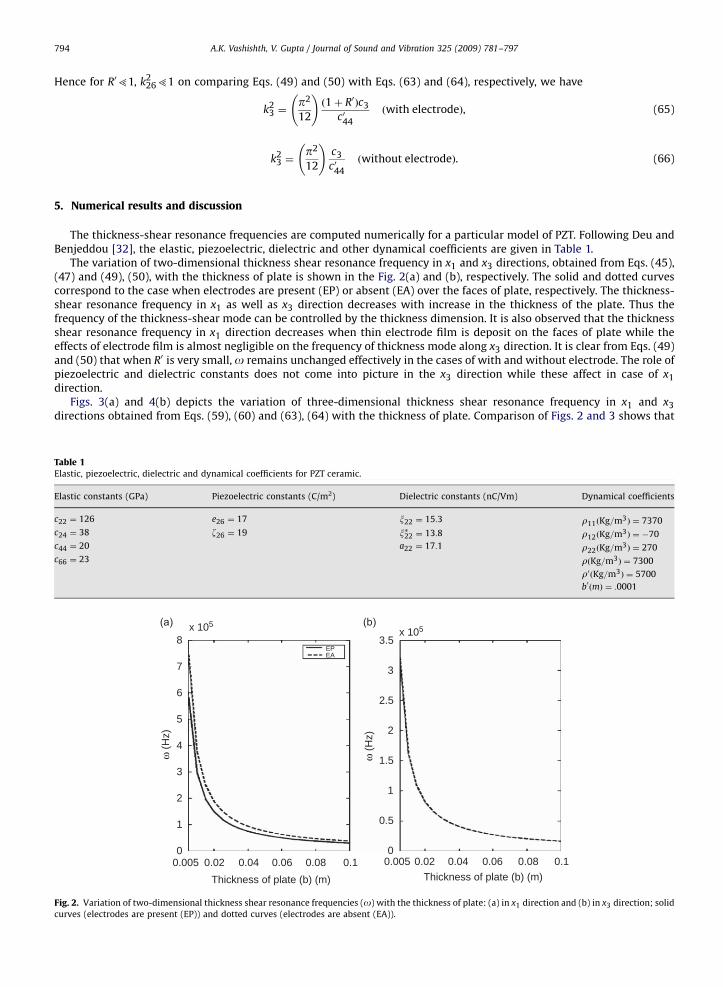
The thickness-shear resonance frequencies are computed numerically for a particular model of PZT. Following Deu andBenjeddou [32], the elastic, piezoelectric, dielectric and other dynamical coefficients are given in Table 1.
The variation of two-dimensional thickness shear resonance frequency in x1 and x3 directions, obtained from Eqs. (45),(47) and (49), (50), with the thickness of plate is shown in the Fig. 2(a) and (b), respectively. The solid and dotted curvescorrespond to the case when electrodes are present (EP) or absent (EA) over the faces of plate, respectively. The thickness-shear resonance frequency in x1 as well as x3 direction decreases with increase in the thickness of the plate. Thus thefrequency of the thickness-shear mode can be controlled by the thickness dimension. It is also observed that the thicknessshear resonance frequency in x1 direction decreases when thin electrode film is deposit on the faces of plate while theeffects of electrode film is almost negligible on the frequency of thickness mode along x3 direction. It is clear from Eqs. (49)and (50) that when R0 is very small, o remains unchanged effectively in the cases of with and without electrode. The role ofpiezoelectric and dielectric constants does not come into picture in the x3 direction while these affect in case of x1
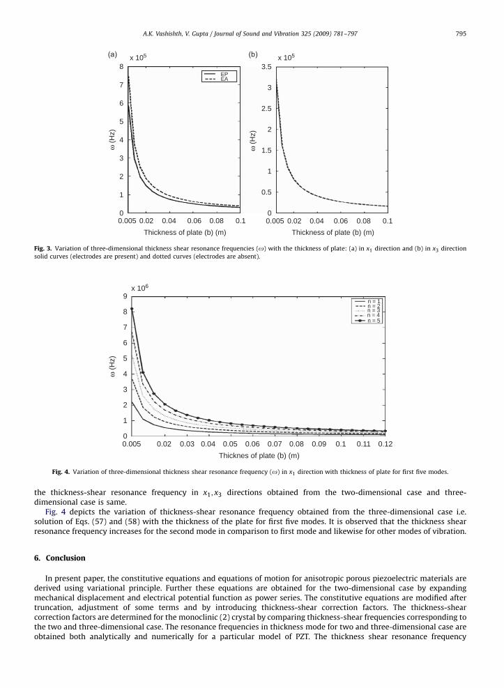
direction.Figs. 3(a) and 4(b) depicts the variation of three-dimensional thickness shear resonance frequency in x1 and x3
directions obtained from Eqs. (59), (60) and (63), (64) with the thickness of plate. Comparison of Figs. 2 and 3 shows that
Table 1Elastic, piezoelectric, dielectric and dynamical coefficients for PZT ceramic.
Elastic constants (GPa) Piezoelectric constants (C/m2) Dielectric constants (nC/Vm) Dynamical coefficients
c22 ¼ 126 e26 ¼ 17 x22 ¼ 15:3 r11ðKg=m3Þ ¼ 7370
c24 ¼ 38 z26 ¼ 19 x�22 ¼ 13:8 r12ðKg=m3Þ ¼ �70
c44 ¼ 20 a22 ¼ 17:1 r22ðKg=m3Þ ¼ 270
c66 ¼ 23 rðKg=m3Þ ¼ 7300
r0ðKg=m3Þ ¼ 5700
b0ðmÞ ¼ :0001
x 105
8
7
6
5
4
3
2
1
0
ω (H
z)
0.005 0.02 0.04 0.06 0.08 0.1 0.005
Thickness of plate (b) (m)
3.5
3
2.5
2
1.5
1
0.5
0
ω (H
z)
0.02 0.04 0.06 0.08 0.1Thickness of plate (b) (m)
x 105
EPEA
Fig. 2. Variation of two-dimensional thickness shear resonance frequencies (o) with the thickness of plate: (a) in x1 direction and (b) in x3 direction; solid
curves (electrodes are present (EP)) and dotted curves (electrodes are absent (EA)).
ARTICLE IN PRESS
x 106
9
8
7
6
5
4
3
2
1
0
ω (H
z)
0.005 0.02 0.03 0.04 0.05 0.06 0.07 0.08 0.09 0.1 0.11 0.12Thicknes of plate (b) (m)
n = 1n = 2n = 3n = 4n = 5
Fig. 4. Variation of three-dimensional thickness shear resonance frequency (o) in x1 direction with thickness of plate for first five modes.
x 105
8
7
6
5
4
3
2
1
0
ω (H
z)
0.005 0.02 0.04 0.06 0.08 0.1 0.005Thickness of plate (b) (m)
3.5
3
2.5
2
1.5
1
0.5
0
ω (H
z)
0.02 0.04 0.06 0.08 0.1Thickness of plate (b) (m)
x 105
EPEA
Fig. 3. Variation of three-dimensional thickness shear resonance frequencies (o) with the thickness of plate: (a) in x1 direction and (b) in x3 direction
solid curves (electrodes are present) and dotted curves (electrodes are absent).
A.K. Vashishth, V. Gupta / Journal of Sound and Vibration 325 (2009) 781–797 795
the thickness-shear resonance frequency in x1; x3 directions obtained from the two-dimensional case and three-dimensional case is same.
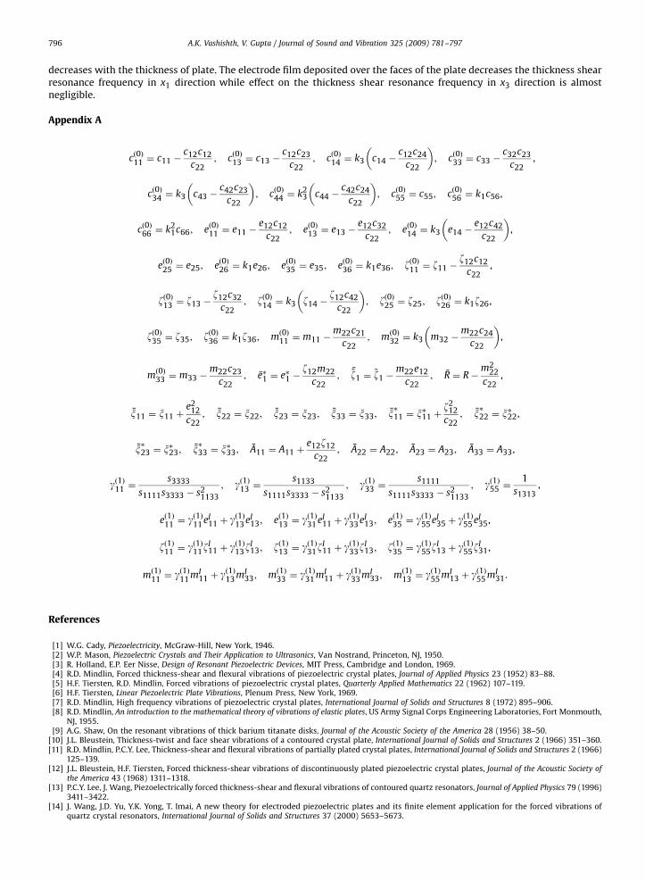
Fig. 4 depicts the variation of thickness-shear resonance frequency obtained from the three-dimensional case i.e.solution of Eqs. (57) and (58) with the thickness of the plate for first five modes. It is observed that the thickness shearresonance frequency increases for the second mode in comparison to first mode and likewise for other modes of vibration.
6. Conclusion
In present paper, the constitutive equations and equations of motion for anisotropic porous piezoelectric materials arederived using variational principle. Further these equations are obtained for the two-dimensional case by expandingmechanical displacement and electrical potential function as power series. The constitutive equations are modified aftertruncation, adjustment of some terms and by introducing thickness-shear correction factors. The thickness-shearcorrection factors are determined for the monoclinic (2) crystal by comparing thickness-shear frequencies corresponding tothe two and three-dimensional case. The resonance frequencies in thickness mode for two and three-dimensional case areobtained both analytically and numerically for a particular model of PZT. The thickness shear resonance frequency
ARTICLE IN PRESS
A.K. Vashishth, V. Gupta / Journal of Sound and Vibration 325 (2009) 781–797796
decreases with the thickness of plate. The electrode film deposited over the faces of the plate decreases the thickness shearresonance frequency in x1 direction while effect on the thickness shear resonance frequency in x3 direction is almostnegligible.
Appendix A
cð0Þ11 ¼ c11 �c12c12
c22; cð0Þ13 ¼ c13 �
c12c23
c22; cð0Þ14 ¼ k3 c14 �
c12c24
c22
� �; cð0Þ33 ¼ c33 �
c32c23
c22,
cð0Þ34 ¼ k3 c43 �c42c23
c22
� �; cð0Þ44 ¼ k2
3 c44 �c42c24
c22
� �; cð0Þ55 ¼ c55; cð0Þ56 ¼ k1c56,
cð0Þ66 ¼ k21c66; eð0Þ11 ¼ e11 �
e12c12
c22; eð0Þ13 ¼ e13 �
e12c32
c22; eð0Þ14 ¼ k3 e14 �
e12c42
c22
� �,
eð0Þ25 ¼ e25; eð0Þ26 ¼ k1e26; eð0Þ35 ¼ e35; eð0Þ36 ¼ k1e36; zð0Þ11 ¼ z11 �z12c12
c22,
zð0Þ13 ¼ z13 �z12c32
c22; zð0Þ14 ¼ k3 z14 �
z12c42
c22
� �; zð0Þ25 ¼ z25; zð0Þ26 ¼ k1z26,
zð0Þ35 ¼ z35; zð0Þ36 ¼ k1z36; mð0Þ11 ¼ m11 �m22c21
c22; mð0Þ32 ¼ k3 m32 �
m22c24
c22
� �,
mð0Þ33 ¼ m33 �m22c23
c22; e�1 ¼ e�1 �
z12m22
c22; ~z1 ¼
~z1 �m22e12
c22; R ¼ R�
m222
c22,
x11 ¼ x11 þe2
12
c22; x22 ¼ x22; x23 ¼ x23; x33 ¼ x33; x�11 ¼ x�11 þ
z212
c22; x�22 ¼ x�22,
x�23 ¼ x�23; x�33 ¼ x�33; A11 ¼ A11 þe12z12
c22; A22 ¼ A22; A23 ¼ A23; A33 ¼ A33,
gð1Þ11 ¼s3333
s1111s3333 � s21133
; gð1Þ13 ¼s1133
s1111s3333 � s21133
; gð1Þ33 ¼s1111
s1111s3333 � s21133
; gð1Þ55 ¼1
s1313,
eð1Þ11 ¼ gð1Þ11 eI11 þ g
ð1Þ13 eI
13; eð1Þ13 ¼ gð1Þ31 eI11 þ g
ð1Þ33 eI
13; eð1Þ35 ¼ gð1Þ55 eI35 þ g
ð1Þ55 eI
35,
zð1Þ11 ¼ gð1Þ11zI11 þ g
ð1Þ13z
I13; zð1Þ13 ¼ gð1Þ31z
I11 þ g
ð1Þ33z
I13; zð1Þ35 ¼ gð1Þ55z
I13 þ g
ð1Þ55z
I31,
mð1Þ11 ¼ gð1Þ11 mI11 þ g
ð1Þ13 mI
33; mð1Þ33 ¼ gð1Þ31 mI11 þ g
ð1Þ33 mI
33; mð1Þ13 ¼ gð1Þ55 mI13 þ g
ð1Þ55 mI
31.
References
[1] W.G. Cady, Piezoelectricity, McGraw-Hill, New York, 1946.[2] W.P. Mason, Piezoelectric Crystals and Their Application to Ultrasonics, Van Nostrand, Princeton, NJ, 1950.[3] R. Holland, E.P. Eer Nisse, Design of Resonant Piezoelectric Devices, MIT Press, Cambridge and London, 1969.[4] R.D. Mindlin, Forced thickness-shear and flexural vibrations of piezoelectric crystal plates, Journal of Applied Physics 23 (1952) 83–88.[5] H.F. Tiersten, R.D. Mindlin, Forced vibrations of piezoelectric crystal plates, Quarterly Applied Mathematics 22 (1962) 107–119.[6] H.F. Tiersten, Linear Piezoelectric Plate Vibrations, Plenum Press, New York, 1969.[7] R.D. Mindlin, High frequency vibrations of piezoelectric crystal plates, International Journal of Solids and Structures 8 (1972) 895–906.[8] R.D. Mindlin, An introduction to the mathematical theory of vibrations of elastic plates, US Army Signal Corps Engineering Laboratories, Fort Monmouth,
NJ, 1955.[9] A.G. Shaw, On the resonant vibrations of thick barium titanate disks, Journal of the Acoustic Society of the America 28 (1956) 38–50.
[10] J.L. Bleustein, Thickness-twist and face shear vibrations of a contoured crystal plate, International Journal of Solids and Structures 2 (1966) 351–360.[11] R.D. Mindlin, P.C.Y. Lee, Thickness-shear and flexural vibrations of partially plated crystal plates, International Journal of Solids and Structures 2 (1966)
125–139.[12] J.L. Bleustein, H.F. Tiersten, Forced thickness-shear vibrations of discontinuously plated piezoelectric crystal plates, Journal of the Acoustic Society of
the America 43 (1968) 1311–1318.[13] P.C.Y. Lee, J. Wang, Piezoelectrically forced thickness-shear and flexural vibrations of contoured quartz resonators, Journal of Applied Physics 79 (1996)
3411–3422.[14] J. Wang, J.D. Yu, Y.K. Yong, T. Imai, A new theory for electroded piezoelectric plates and its finite element application for the forced vibrations of
quartz crystal resonators, International Journal of Solids and Structures 37 (2000) 5653–5673.
ARTICLE IN PRESS
A.K. Vashishth, V. Gupta / Journal of Sound and Vibration 325 (2009) 781–797 797
[15] W.Q. Chen, Vibration theory of non-homogeneous spherically isotropic piezoelastic bodies, Journal of Sound and Vibration 236 (2000) 833–860.[16] V.M. Bazhenov, Longitudinal vibration of piezoceramic rods, Journal of Mathematical Sciences 103 (2001) 240–244.[17] J.C. Piquette, Quasistatic coupling coefficients for electrostrictive ceramics, Journal of the Acoustic Society of the America 111 (2001) 197–207.[18] J.S. Yang, Shear horizontal vibrations of piezoelectric/ferroelectric wedge, Acta Mechanica 173 (2004) 13–17.[19] E. Lioubimova, P. Schiavone, Steady-state vibrations of an unbounded linear piezoelectric medium, Zeitschrift fur Angewandte Mathematik und Physik
ZAMP 57 (2006) 862–874.[20] S.Y. He, W.S. Chen, Z.L. Chen, A uniformizing method for the free vibration analysis of metal–piezoceramic composite thin plates, Journal of Sound and
Vibration 217 (1998) 261–281.[21] H. Ding, R. Xu, Y. Chi, W. Chen, Free axisymmetric vibrations of transversely isotropic piezoelectric circular plates, International Journal of Solids and
Structures 36 (1999) 4629–4652.[22] H. Ding, R.Q. Xu, W. Chen, Exact solutions for free vibration of transversely isotropic piezoelectric circular plates, Acta Mechanica Sinica 16 (2000)
142–147.[23] H.J. Ding, W.Q. Chen, R.Q. Xu, On the bending, vibration and stability of laminated rectangular plates with transversely isotropic layers, Applied
Mathematics and Mechanics 22 (2001) 17–24.[24] Y. Wang, R.Q. Xu, H.J. Ding, Free vibration of piezoelectric annular plate, Journal of Zhejiang University Science 4 (2003) 379–387.[25] V.L. Karlash, Resonant electromechanical vibrations of piezoelectric plates, International Applied Mechanics 41 (2005) 709–747.[26] W.Q. Chen, H.J. Ding, On free vibration of a functionally graded piezoelectric rectangular plate, Acta Mechanica 153 (2002) 207–216.[27] W.Q. Chen, Z.G. Bian, C.F. Lv, H.J. Ding, 3D free vibration analysis of a functionally graded piezoelectric hollow cylinder filled with compressible fluid,
International Journal of Solids and Structures 41 (2004) 947–964.[28] S.M. Yang, J.W. Chiu, Smart structures-vibration of composites with piezoelectric materials, Composites Structure 25 (1993) 381–386.[29] P.R. Heyliger, G. Ramirez, Free vibration of laminated circular piezoelectric plates and discs, Journal of Sound and Vibration 229 (2000) 935–956.[30] J.A. Hernandes, S.F.M. Almeida, A. Naborrete, Stiffening effects on the free vibration behaviour of composite plates with PZT actuators, Composite
Structures 49 (2000) 55–63.[31] S.V. Senthil, R.C. Mewer, R.C. Batra, Analytical solution for the cylindrical bending vibration of piezoelectric composite plates, International Journal of
Solids and Structures 41 (2004) 1625–1643.[32] J.F. Deu, A. Benjeddou, Free vibration analysis of laminated plates with embedded shear-mode piezoceramic layers, International Journal of Solids and
Structures 42 (2005) 2059–2088.[33] X. Shu, Free vibration of laminated piezoelectric composite plates based on an accurate theory, Composite Structures 67 (2005) 375–382.[34] G. Qing, J. Qiu, Y. Liu, Free vibration analysis of stiffened laminated plates, International Journal of Solids and Structures 43 (2006) 1357–1371.[35] P. Topdar, A.H. Sheikh, N. Dhang, Vibration characteristics of composite/sandwich laminates with piezoelectric layers using a refined hybrid plate
model, International Journal of Mechanical Sciences 49 (2007) 1193–1203.[36] R.D. Mindlin, Equations of high frequency vibrations of thermopiezoelectric crystal plates, International Journal of Solids and Structures 10 (1974)
625–637.[37] K. Xu, A.K. Noor, Y.Y. Tang, Three dimensional solutions for free vibrations of initially stressed thermoelectroelastic multilayered plates, Computer
Methods in Applied Mechanics and Engineering 141 (1997) 125–139.[38] S.K. Parashar, U.V. Wagner, Nonlinear longitudinal vibrations of transversely polarized piezoceramics: experiments and modeling, Nonlinear
Dynamics 37 (2004) 51–73.[39] S.K. Parashar, A. Dasgupta, U.V. Wagner, P. Hagedorn, Non-linear shear vibrations of piezoceramic actuators, International Journal of Non-linear
Mechanics 40 (2005) 429–443.[40] X.L. Huang, H.S. Shen, Nonlinear free and forced vibration of simply supported shear deformable laminated plates with piezoelectric actuators,
International Journal of Mechanical Sciences 47 (2005) 187–208.[41] L.P. Khoroshun, T.I. Dorodnykh, Piezoelectrics of polycrystalline structures, Soviet Applied Mechanics 27 (1991) 660–665.[42] L.P. Khoroshun, P.V. Leshchenko, T.I. Dorodnykh, Effective electroelastic properties of polycrystals, International Applied Mechanics 30 (1994) 311–319.[43] L.P. Khoroshun, T.I. Dorodnykh, the effective elastic constants of porous polycrystals of trigonal symmetry, International Applied Mechanics 37 (2001)
1290–1303.[44] L.P. Khoroshun, T.I. Dorodnykh, Effective electrostrictive properties of stochastic two-component materials, International Applied Mechanics 44 (2008)
955–962.[45] R.K. Gupta, T.A. Venkatesh, Electromechanical response of porous piezoelectric materials, Acta Materialia 54 (2006) 4063–4078.[46] A.L. Cauchy, Sur l’equilibre et le movement d’une plaque don’t l’elasticite n’est pas la meme dans tous les sens, Exercise de Mathematique 4 (1829)
1–14.[47] R.D. Mindlin, High frequency vibrations of plated, crystal plates, Progress in Applied Mechanics, Praeger Anniversary Volume (1963) 73–84.