Embed Size (px)
Citation preview
© 2014. Mateus Zimmer Dietrich, Felipe Barbosa Teixeira, Adenilcia Fernanda Grobério Calenzani & Walnório Graça Ferreira.
This is a research/review paper, distributed under the terms of the Creative Commons Attribution-Noncommercial 3.0 Unported License http://creativecommons.org/ licenses/by-nc/3.0/), permitting all non commercial use, distribution, and reproduction in any medium, provided the original work is properly cited.
Global Journal of Researches in Engineering: e Civil And Structural Engineering Volume 14 Issue 3 Version 1.0 Year 2014 Type: Double Blind Peer Reviewed International Research Journal Publisher: Global Journals Inc. (USA) Online ISSN: 2249-4596 & Print ISSN: 0975-5861
Vibrations in Steel-Frame Floors due to Human Activities
By Mateus Zimmer Dietrich, Felipe Barbosa Teixeira, Adenilcia Fernanda Grobério Calenzani & Walnório Graça Ferreira
Federal University of Espírito Santo, Brazil
Abstract- Architectural new tendencies along with current market demands are taking engineering design towards the use of flooring systems which can span great distances with a minimum number of columns allowing, thus, more architectural flexibility. This design philosophy has conducted to ever more slender structural elements, with ever lower natural frequencies that are, therefore, closer to the frequency bands of dynamic excitations associated to human activities, such as walking. Within this context, this paper studies the behaviour of the following flooring systems: (a) reinforced concrete slabs supported by steel beams, and (b) steel floor plates supported by steel beams. The evaluation of the natural frequencies of the structure and its responses (floor displacements and accelerations) to the walking activity were analyzed by the simplified analytical method of AISC 360-10 code. The flooring systems were modeled using the finite element software ANSYS 14.0™ and the numerical results for natural frequencies and floor accelerations were compared with those obtained by the simplified procedure of the AISC 360-10 code. This way, it was possible to draw conclusions about the dynamic behaviour of the analyzed flooring systems.
Keywords: flooring systems, walking loading, dynamic behaviour, structural vibrations.
GJRE-E Classification : FOR Code: 861103, 090599
VibrationsinSteelFrameFloorsduetoHumanActivities Strictly as per the compliance and regulations of :
Vibrations in Steel-Frame Floors due to Human Activities
Mateus Zimmer Dietrich α, Felipe Barbosa Teixeira
σ, Adenilcia Fernanda Grobério Calenzani ρ
& Walnório Graça Ferreira Ѡ
Abstract- Architectural new tendencies along with current market demands are taking engineering design towards the use of flooring systems which can span great distances with a minimum number of columns allowing, thus, more architectural flexibility. This design philosophy has conducted to ever more slender structural elements, with ever lower natural frequencies that are, therefore, closer to the frequency bands of dynamic excitations associated to human activities, such as walking. Within this context, this paper studies the behaviour of the following flooring systems: (a) reinforced concrete slabs supported by steel beams, and (b) steel floor plates supported by steel beams. The evaluation of the natural frequencies of the structure and its responses (floor displacements and accelerations) to the walking activity were analyzed by the simplified analytical method of AISC 360-10 code. The flooring systems were modeled using the finite element software ANSYS 14.0™ and the numerical results for natural frequencies and floor accelerations were compared with those obtained by the simplified procedure of the AISC 360-10 code. This way, it was possible to draw conclusions about the dynamic behaviour of the analyzed flooring systems. Keywords: flooring systems, walking loading, dynamic behaviour, structural vibrations.
I. Introduction rchitectural new tendencies along with current market demands are taking
engineering design
towards the use of flooring systems which can
span great distances with a minimum number of pillars allowing, thus, more architectural flexibility. This design philosophy has conducted to ever more slender structural elements, with ever lower natural frequencies that are, therefore, closer to the frequency bands of dynamic excitations associated to human activities, such as walking.
Within this context, studies about the dynamic behaviour of commonly employed flooring systems become necessary for the evaluation of the service conditions of buildings subject to vibrations caused by human activities such as walking.
Brazilian Standard NBR 8800:2008 covers this topic very superficially. Annex L points restrictions only on
the natural frequency of the floor, furnishing a
simplified evaluation
that
depends on
the total vertical
Author α σ ρ Ѡ: Civil Engineering, Department.Universidade Federal do Espírito Santo, Av Fernando Ferrari, 514 CEP 29075-910, Vitória ES Brazil. e-mails: [email protected], [email protected], [email protected], [email protected]
displacement of the floor. However, the standard signals
that this evaluation might not be adequate for the problem and leaves its application to the discretion of the engineer.
The CEB (1991) standard treats the subject in a broader manner, furnishing graphical and analytical representations for human activities, pointing some factors that influence the damping of a structure, the effects caused by vibrations on people and on the structure, tolerable acceleration values, corrective measures, and more. It is interesting to point out that the manual presents two simplified design rules. The first,
High Tuning Method, being simple and efficient,
limits the fundamental frequency of the floor with respect to its damping rate. This method, though, can be quite conservative. And the second, Method of Heel Impact, presents simple procedures for the computation of the frequency and initial peak acceleration of the floor.
The AISC 360-10 standard, through Murray et al. (2003) Design Guide, also treats the subject and presents simple analytical tools for the verification of flooring systems subjected to vibrations. In a similar way to the method described by CEB, firstly the frequency is calculated, followed by the peak acceleration. The standard not only presents a broader application as compared to the most commonly used methods, but also has its own criterion based on the dynamic response of flooring systems supported by steel beams subject to walking loading, consisting, therefore, the utilized tool in this study.
Following this directive, Mello (2005) developed numerical analyses in flooring systems subject to human activities and compared the obtained results with the simplified calculation method of AISC 360-10. Pretti (2012) performed a study about the different simplified procedures for determining peak acceleration of flooring systems subject to human activities and applied these procedures in numerical examples.
II.
SIMPLIFIED
CALCULATION
METHOD
The Steel Design Guide by Murray et al. (2003)
presents, in accordance to American Standard AISC 360-10, a simplified analytical method for determining the frequency and the acceleration of a flooring system.
The following described method is applied to floor panels subject to the human activity of walking,
A
© 2014 Global Journals Inc. (US)
Gl oba
l Jo
urna
l of
Resea
rche
s in E
nginee
ring
()
Volum
e X
IV
Issu
e III
Version
I
1
Year
2014
E
made of concrete slabs or composite slabs with steel beams.
a)
Floor Natural Frequency
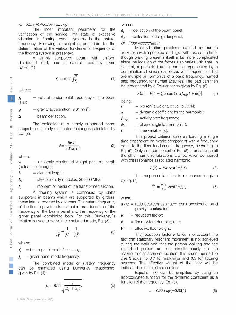
The most important parameter for the verification of the service limit state of excessive vibration in flooring panel systems is the natural frequency. Following, a simplified procedure for the determination of the vertical fundamental frequency of the flooring system is presented.
A simply supported beam, with uniform
distributed load, has its natural frequency given
by Eq. (1).
𝑓𝑓𝑛𝑛 = 0.18�𝑔𝑔∆ ,
(1)
where:
𝑓𝑓𝑛𝑛
= natural fundamental frequency of the beam
[Hz];
𝑔𝑔
= gravity acceleration, 9.81 m/s2; ∆
= beam deflection.
The deflection of a simply supported beam
subject to uniformly distributed loading is calculated by Eq. (2).
∆=5𝑤𝑤𝐿𝐿4
384𝐸𝐸𝑆𝑆𝐼𝐼𝑇𝑇,
(2)
where: 𝑤𝑤 = uniformly distributed weight per unit length (actual, not design);
𝐿𝐿 = element length;
𝐸𝐸𝑆𝑆 = steel elasticity modulus, 200000 MPa;
𝐼𝐼𝑇𝑇 = moment of inertia of the transformed section.
A flooring system is composed by slabs supported in beams which are supported by girders, these later supported by columns. The natural frequency of the flooring system is estimated as a function of the frequency of the beam panel and the frequency of the girder panel, combining both. For this, Dunkerley´s relation is used to derive the combined mode, Eq. (3):
1𝑓𝑓𝑛𝑛2
=1𝑓𝑓𝑗𝑗2
+1𝑓𝑓𝑔𝑔2
,
(3)
where:
𝑓𝑓𝑗𝑗 = beam panel mode frequency;
𝑓𝑓𝑔𝑔 = girder panel mode frequency.
The combined mode or system frequency
can be estimated using Dunkerley relationship,
given by Eq. (4):
𝑓𝑓𝑛𝑛 = 0.18�𝑔𝑔
(∆𝑗𝑗 + ∆𝑔𝑔) ,
(4)
where:
∆𝑗𝑗 = deflection
of the beam panel;
∆𝑔𝑔 = deflection
of the girder panel;
b)
Floor Acceleration
Most vibration problems caused by human activities involve periodic loadings, with respect to time, though walking presents itself a bit more complicated since the location of the forces also varies with time. In general, a periodic loading can be represented by a combination of sinusoidal forces with frequencies that are multiple or harmonics of a basic frequency, named step frequency, for human activities. The load can then be represented by a Fourier series given by Eq. (5).
𝑃𝑃(𝑡𝑡) = 𝑃𝑃�1 + ∑𝛼𝛼𝑖𝑖cos �2𝜋𝜋𝑖𝑖𝑓𝑓𝑠𝑠𝑡𝑡𝑠𝑠𝑠𝑠 𝑡𝑡 + 𝜙𝜙𝑖𝑖��,
(5)
being:
𝑃𝑃
= person´s weight, equal to 700N;
𝛼𝛼𝑖𝑖
= dynamic coefficient for the harmonic 𝑖𝑖;
𝑓𝑓𝑠𝑠𝑡𝑡𝑠𝑠𝑠𝑠
= activity step frequency;
𝜙𝜙𝑖𝑖 = phase angle for harmonic 𝑖𝑖;
𝑡𝑡
= time variable [s].
This project criterion uses as loading a single time dependent harmonic component with a frequency equal to the floor fundamental frequency, according to Eq. (6). Only one component of Eq. (5) is used since all the other harmonic vibrations are low when compared with the resonance associated harmonic.
𝑃𝑃(𝑡𝑡) = 𝑃𝑃𝛼𝛼 cos(2𝜋𝜋𝑓𝑓𝑛𝑛𝑡𝑡).
(6)
The response function in resonance is given
by Eq. (7).
𝑎𝑎𝑃𝑃𝑔𝑔
= 𝑃𝑃𝑃𝑃𝛼𝛼𝑖𝑖𝛽𝛽𝛽𝛽
cos(2𝜋𝜋𝑓𝑓𝑛𝑛𝑡𝑡), (7)
where:
𝑎𝑎𝑃𝑃/𝑔𝑔 = ratio between estimated peak acceleration and
gravity acceleration;
𝑃𝑃
= reduction factor;
𝛽𝛽
= floor system damping rate;
𝛽𝛽
= effective floor weight.
The reduction factor 𝑃𝑃
takes into account the fact that stationary resonant movement is not achieved during the walk and that the person walking and the perturbed person are not simultaneously on the maximum displacement location. It is recommended to use
𝑃𝑃
equal to 0.7 for walkways and 0.5 for flooring systems. The effective weight of the floor will be estimated on the next subsection.
Equation (7) can be simplified by using an approximated function for the dynamic coefficient as a function of the frequency, Eq. (8).
𝛼𝛼 = 0.83 exp(−0.35𝑓𝑓) (8)
Vibrations in Steel-Frame Floors due to Human Activities
© 2014 Global Journals Inc. (US)
Globa
l Jo
urna
l of
Resea
rche
s in E
nginee
ring
()
Volum
e X
IV
Issu
e III
Version
I
Year
2014
2
E
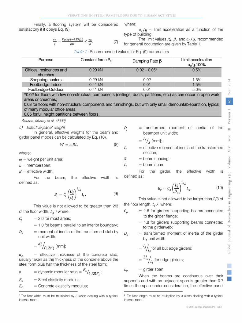
Finally, a flooring system will be considered satisfactory if it obeys Eq. (9).
𝑎𝑎𝑃𝑃𝑔𝑔
= 𝑃𝑃0𝑠𝑠𝑒𝑒𝑠𝑠 (−0.35𝑓𝑓𝑛𝑛 )𝛽𝛽𝛽𝛽
≤ 𝑎𝑎0𝑔𝑔
,
(7)
where:
𝑎𝑎0/𝑔𝑔
= limit acceleration as a function of thetype of building;
The limit values 𝑃𝑃0, 𝛽𝛽, and 𝑎𝑎0/𝑔𝑔, recommended for general occupation are given by Table 1.
Table 1 : Recommended values for Eq. (9) parameters
Purpose
Constant force P0
Damping Rate β
Limit acceleration a0/g.100%
Offices, residences and churches
0.29 kN
0.02 – 0.05*
0.5%
Shopping centers
0.29 kN
0.02
1.5%
Footbridge-Indoor
0.41 kN
0.01
1.5%
Footbridge-Outdoor
0.41 kN
0.01
5.0%
*0.02 for floors with few non-structural components (ceilings, ducts, partitions, etc.) as can occur in open work areas or churches;
0.03 for floors with non-structural components and furnishings, but with only small demountablepartition, typical of many modular office areas;
0.05 forfull height partitions between floors.
Source: Murray et al. (2003)
c)
Effective
panel
weight
In general, effective weights for the beam and girder panel modes can be calculated by Eq. (10).
𝛽𝛽 = 𝜔𝜔𝜔𝜔𝐿𝐿,
(8)
where:
𝜔𝜔
= weight per unit area;
𝐿𝐿
= memberspan;
𝜔𝜔
= effective width.
For the beam, the effective width is
defined as:
𝜔𝜔𝑗𝑗 = 𝐶𝐶𝑗𝑗 �𝐷𝐷𝑆𝑆𝐷𝐷𝑗𝑗�
14�
𝐿𝐿𝑗𝑗 .
(9)
This value is not allowed to be greater than 2/3 of the floor width, 𝐿𝐿𝑔𝑔 ,1
where:
𝐶𝐶𝑗𝑗
= 2.0 for most areas;
= 1.0 for beams parallel to an interior boundary;
𝐷𝐷𝑆𝑆
= moment of inertia of the transformed slab by
unit width;
= 𝑑𝑑𝑠𝑠3
(12𝑛𝑛)�
[mm];
𝑑𝑑𝑠𝑠
= effective thickness of the concrete slab, usually taken as the thickness of the concrete above the steel form plus half the thickness of the steel form;
𝑛𝑛
= dynamic modular ratio = 𝐸𝐸𝑆𝑆 1.35𝐸𝐸𝐶𝐶� ;
𝐸𝐸𝑆𝑆
= Steel elasticity modulus;
𝐸𝐸𝐶𝐶
= Concrete elasticity modulus;
1 The floor width must be multiplied by 3 when dealing with a typical internal room.
𝐷𝐷𝑗𝑗
= transformed moment of inertia of the beamper unit width;
= 𝐼𝐼𝑇𝑇 𝑆𝑆�
[mm];
𝐼𝐼𝑇𝑇
= effective moment of inertia of the transformed section;
𝑆𝑆
= beam spacing;
𝐿𝐿𝑗𝑗
= beam span.
For the girder, the effective width is
defined as:
𝜔𝜔𝑔𝑔 = 𝐶𝐶𝑔𝑔 �𝐷𝐷𝑗𝑗𝐷𝐷𝑔𝑔�
14�
𝐿𝐿𝑔𝑔 .
(10)
This value is not allowed to be larger than 2/3 of the floor length, 𝐿𝐿𝑗𝑗 ,2 where:
𝐶𝐶𝑔𝑔
= 1.6 for girders supporting beams connected to the girder flange;
= 1.8 for girders supporting beams connected to the girderweb;
𝐷𝐷𝑔𝑔
= transformed moment of inertia of the girder by unit width;
= 𝐼𝐼𝑔𝑔𝐿𝐿𝑗𝑗� for all but edge girders;
= 2𝐼𝐼𝑔𝑔
𝐿𝐿𝑗𝑗�
for edge girders;
𝐿𝐿𝑔𝑔
= girder span.
When the beams are continuous over their supports and with an adjacent span is greater than 0.7 times the span under consideration, the effective panel 2 The floor length must be multiplied by 3 when dealing with a typical internal room.
Vibrations in Steel-Frame Floors due to Human Activities
© 2014 Global Journals Inc. (US)
Gl oba
l Jo
urna
l of
Resea
rche
s in E
nginee
ring
()
Volum
e X
IV
Issu
e III
Version
I
3
Year
2014
E
weight, 𝛽𝛽𝑗𝑗 or 𝛽𝛽𝑔𝑔 , can be increased by 50%. This liberalization can also be applied to rolled steel beams connected (by shear) to the web of the girder, but not to trusses connected only at their top chord.
For the combined mode, the equivalent panel weight is approximated using Eq. (13).
𝛽𝛽 =Δ𝑗𝑗
Δ𝑗𝑗 + Δ𝑔𝑔𝛽𝛽𝑗𝑗 +
Δ𝑔𝑔Δ𝑗𝑗 + Δ𝑔𝑔
𝛽𝛽𝑔𝑔 ,
(11)
where:
Δ𝑗𝑗
and Δg
= aximum deflexions of thebeam and girder, respectively, due to the supported load;
Wj
and
𝛽𝛽𝑔𝑔
= fective panel weights for the beam and girders panels, respectively.
If the girder span is less than the width of the beam panel,𝐿𝐿𝑔𝑔 < 𝜔𝜔𝑗𝑗 , the girder deflection, Δ𝑔𝑔 , used in Eq. (13) is reduced to:
Δ𝑔𝑔´ =𝐿𝐿𝑔𝑔𝜔𝜔𝑗𝑗�Δ𝑔𝑔�,
(12)
and
0.5 ≤ 𝐿𝐿𝑔𝑔𝜔𝜔𝑗𝑗� ≤ 1.0.
If 𝐿𝐿𝑗𝑗 < 0.5𝐿𝐿𝑔𝑔 , the beam panel mode and the combined mode should be separately verified.
d)
Internal
Flooredges
Internal flooredges, require special consideration as a consequence of the reduced mass reduction due to the free edge.
When the edge member is a beam, the practical solution is to stiffen the edge, either by the addition of another beam or by the substitution of this member by another one that should have a 50% higher moment of inertia. If edge beam is not stiffened, its verification should be made using 𝐶𝐶𝑗𝑗 = 1.0
on Eq. (11).
When the edge member is a girder, the verification should be made according to the described procedure, except by the fact that the effective width (𝜔𝜔𝑔𝑔 ) should be taken equal to 2/3 of the secondary supported beam span.
The experience has shown that external floors edges of buildings do not require special attention such as the internal floor edges. The reason for this is the stiffening due to the external cladding and walkways which in general are not adjacent to external walls.
III.
SIMPLIFIED
CALCULATION
METHOD
a)
About the
used Software
For the numerical analysis was used the ANSYS 14.0™. This software is quite rich with respect to the
element library, the possible types of structural analysis, and the available numerical resources. Besides that, ANSYS 14.0™has been well utilized by the scientific community in numerical simulations to analyze the dynamic behaviour of structures.
b)
Structural
Model
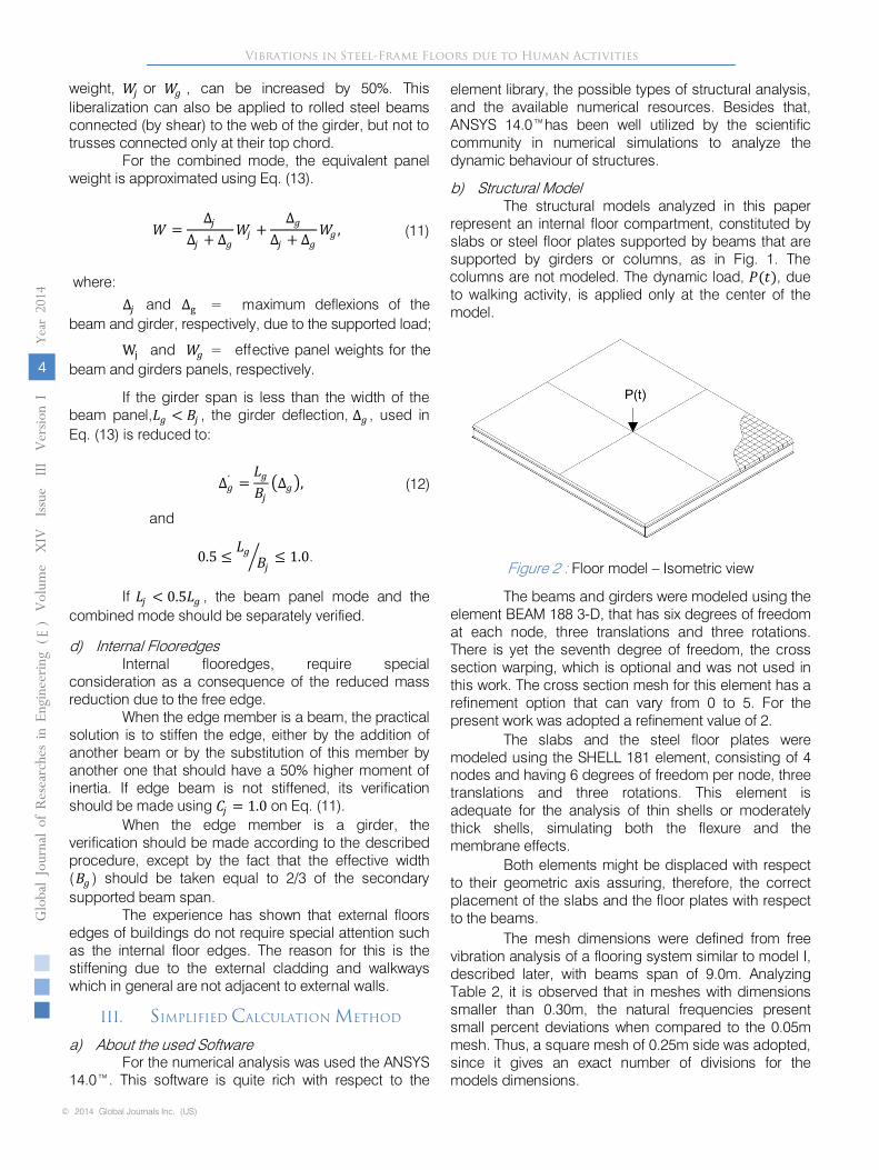
The structural models analyzed in this paper represent an internal floor compartment, constituted by slabs or steel floor plates supported by beams that are supported by girders or columns, as in Fig. 1. The columns are not modeled. The dynamic load, 𝑃𝑃(𝑡𝑡), due to walking activity, is applied only at the center of the model.
Figure 2 : Floor model –
Isometric view
The beams and girders were modeled using the element BEAM 188 3-D, that has six degrees of freedom at each node, three translations and three rotations. There is yet the seventh degree of freedom, the cross section warping, which is optional and was not used in this work. The cross section mesh for this element has a refinement option that can vary from 0 to 5. For the present work was adopted a refinement value of 2.
The slabs and the steel floor plates were modeled using the SHELL 181 element, consisting of 4 nodes and having 6 degrees of freedom per node, three translations and three rotations. This element is adequate for the analysis of
thin shells or moderately thick shells, simulating both the flexure and the membrane effects.
Both elements might be displaced with respect to their geometric axis assuring, therefore, the correct placement of the slabs and the floor plates with respect to the beams.
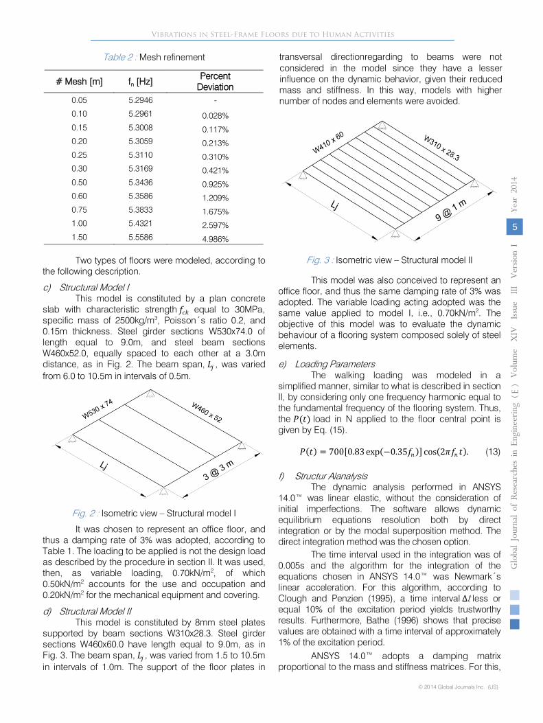
The mesh dimensions were defined from free vibration analysis of a flooring system similar to model I, described later, with beams span of 9.0m. Analyzing Table 2, it is observed that in meshes with dimensions smaller than 0.30m, the natural frequencies present small percent deviations when compared to the 0.05m mesh. Thus, a square mesh of 0.25m side was adopted, since it gives an exact number of divisions for the models dimensions.
Vibrations in Steel-Frame Floors due to Human Activities
© 2014 Global Journals Inc. (US)
Globa
l Jo
urna
l of
Resea
rche
s in E
nginee
ring
()
Volum
e X
IV
Issu
e III
Version
I
Year
2014
4
E
m
ef
0.05
5.2946
-
0.10
5.2961
0.028%
0.15
5.3008
0.117%
0.20
5.3059
0.213%
0.25
5.3110
0.310%
0.30
5.3169
0.421%
0.50
5.3436
0.925%
0.60
5.3586
1.209%
0.75
5.3833
1.675%
1.00
5.4321
2.597%
1.50
5.5586
4.986%
Two types of floors were modeled, according to the following description.
c)
Structural Model I
This model is constituted by a plan concrete slab with characteristic strength 𝑓𝑓𝑐𝑐𝑐𝑐
equal to 30MPa, specific mass of 2500kg/m3, Poisson´s ratio 0.2, and 0.15m thickness. Steel girder sections W530x74.0 of length equal to 9.0m, and steel beam sections W460x52.0, equally spaced to each other at a 3.0m distance, as in Fig. 2. The beam span, 𝐿𝐿𝑗𝑗 , was varied from 6.0 to 10.5m in intervals of 0.5m.
Fig.
2
: Isometric view –
Structural model I
It was
chosen to represent an office floor, and thus a damping rate of 3% was adopted, according to Table 1. The loading to be applied is not the design load as described by the procedure
in section II. It was used, then, as variable loading, 0.70kN/m2, of which 0.50kN/m2
accounts for the use and occupation and 0.20kN/m2
for the mechanical equipment and covering.
d)
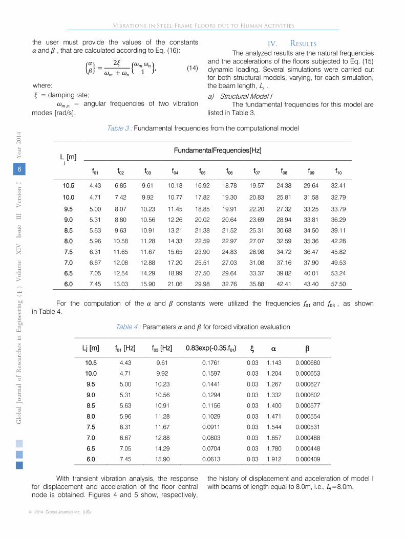
Structural Model II
This model is constituted by 8mm steel plates supported by beam sections W310x28.3. Steel girder sections W460x60.0 have length equal
to 9.0m, as in Fig. 3. The beam span, 𝐿𝐿𝑗𝑗 , was varied from 1.5 to 10.5m in intervals of 1.0m. The support of the floor plates in
transversal directionregarding to beams were not considered in the model since they have a lesser influence on the dynamic
behavior, given their reduced mass and stiffness. In this way, models with higher number of nodes and elements were avoided.
Fig.
3
: Isometric view –
Structural model II
This model was also conceived to represent an office floor, and thus the same damping rate of 3% was adopted. The variable loading acting adopted was the same value applied to model I, i.e., 0.70kN/m2. The objective of this model was to evaluate the dynamic behaviour of a flooring system composed solely of steel elements.
e)
Loading
Parameters
The walking loading was modeled in a simplified manner, similar to what is described in section II, by considering only one frequency harmonic equal to the fundamental frequency of the flooring system. Thus, the 𝑃𝑃(𝑡𝑡)
load in N applied to the floor central point is given by Eq. (15).
𝑃𝑃(𝑡𝑡) = 700[0.83 exp(−0.35𝑓𝑓𝑛𝑛)] cos(2𝜋𝜋𝑓𝑓𝑛𝑛𝑡𝑡).
(13)
f)
Structur
Alanalysis
The dynamic analysis performed in ANSYS 14.0™ was linear elastic, without the consideration of initial imperfections. The software allows dynamic equilibrium equations resolution both by direct integration or by the modal superposition method. The direct integration method was the chosen option.
The time interval used in the integration was of 0.005s and the algorithm for the integration of the equations chosen in ANSYS 14.0™ was Newmark´s linear acceleration. For this algorithm, according to Clough and Penzien (1995), a time interval Δ
less or equal 10% of the excitation period yields trustworthy results. Furthermore, Bathe (1996) shows that precise values are obtained with a time interval of approximately 1% of the excitation period.
ANSYS 14.0™ adopts a damping matrix proportional to the mass and stiffness matrices. For this,
Vibrations in Steel-Frame Floors due to Human Activities
© 2014 Global Journals Inc. (US)
Globa
l Jo
urna
l of
Resea
rche
s in E
nginee
ring
()
Volum
e X
IV
Issu
e III
Version
I
5
Year
2014
E
Table 2 : Mesh refinement
# Mesh [m] fn [Hz] PercentDeviation
t
𝜔𝜔𝑚𝑚 ,𝑛𝑛
= angular frequencies of two vibrationmodes [rad/s].
IV.
RESULTS
The analyzed results are the natural frequencies
and the accelerations of the floors subjected to Eq. (15) dynamic loading. Several simulations
were carried out for both structural models, varying, for each simulation, the beam length, Lj.
.
a)
Structural
Model I
The fundamental frequencies for this model are listed
in Table 3.
Table 3
: Fundamental frequencies from the computational model
Lj
[m]
FundamentalFrequencies[Hz]
f01
f02
f03
f04
f05
f06
f07
f08
f09
f10
10.5
4.43
6.85
9.61
10.18
16.92
18.78
19.57
24.38
29.64
32.41
10.0
4.71
7.42
9.92
10.77
17.82
19.30
20.83
25.81
31.58
32.79
9.5
5.00
8.07
10.23
11.45
18.85
19.91
22.20
27.32
33.25
33.79
9.0
5.31
8.80
10.56
12.26
20.02
20.64
23.69
28.94
33.81
36.29
8.5
5.63
9.63
10.91
13.21
21.38
21.52
25.31
30.68
34.50
39.11
8.0
5.96
10.58
11.28
14.33
22.59
22.97
27.07
32.59
35.36
42.28
7.5
6.31
11.65
11.67
15.65
23.90
24.83
28.98
34.72
36.47
45.82
7.0
6.67
12.08
12.88
17.20
25.51
27.03
31.08
37.16
37.90
49.53
6.5
7.05
12.54
14.29
18.99
27.50
29.64
33.37
39.82
40.01
53.24
6.0
7.45
13.03
15.90
21.06
29.98
32.76
35.88
42.41
43.40
57.50
For the computation of the 𝛼𝛼
and 𝛽𝛽
constants were utilized the frequencies 𝑓𝑓01 and 𝑓𝑓03 , as shown
in Table 4.
Table 4
: Parameters 𝛼𝛼
and 𝛽𝛽
for forced vibration evaluation
Lj [m]
f01
[Hz]
f03
[Hz]
0.83exp(-0.35.f01)
ξ α β
10.5
4.43
9.61
0.1761
0.03
1.143
0.000680
10.0
4.71
9.92
0.1597
0.03
1.204
0.000653
9.5
5.00
10.23
0.1441
0.03
1.267
0.000627
9.0
5.31
10.56
0.1294
0.03
1.332
0.000602
8.5
5.63
10.91
0.1156
0.03
1.400
0.000577
8.0
5.96
11.28
0.1029
0.03
1.471
0.000554
7.5
6.31
11.67
0.0911
0.03
1.544
0.000531
7.0
6.67
12.88
0.0803
0.03
1.657
0.000488
6.5
7.05
14.29
0.0704
0.03
1.780
0.000448
6.0
7.45
15.90
0.0613
0.03
1.912
0.000409
With transient vibration analysis, the response for displacement and acceleration of the floor central node is obtained. Figures 4 and 5 show, respectively,
the history of displacement and acceleration of model I with beams of length equal to 8.0m, i.e., 𝐿𝐿𝑗𝑗=8.0m.
Vibrations in Steel-Frame Floors due to Human Activities
© 2014 Global Journals Inc. (US)
Globa
l Jo
urna
l of
Resea
rche
s in E
nginee
ring
()
Volum
e X
IV
Iss u
e III
Version
I
Year
2014
6
E
�𝛼𝛼𝛽𝛽� =
2𝜉𝜉𝜔𝜔𝑚𝑚 +𝜔𝜔𝑛𝑛
�𝜔𝜔𝑚𝑚𝜔𝜔𝑛𝑛1 �, (14)
where:𝜉𝜉 = damping rate;
the user must provide the values of the constants 𝛼𝛼 and 𝛽𝛽 , that are calculated according to Eq. (16):
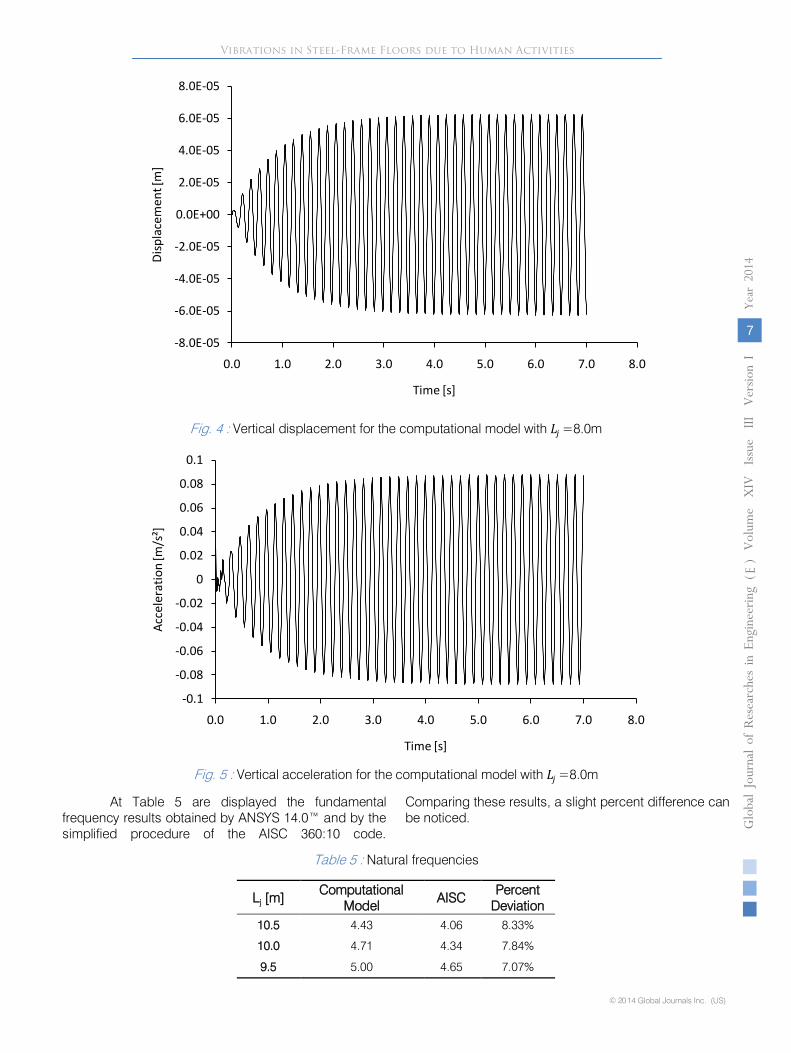
Fig. 4 : Vertical displacement for the computational model with 𝐿𝐿𝑗𝑗 =8.0m
Fig. 5 : Vertical acceleration for the computational model with 𝐿𝐿𝑗𝑗 =8.0m
At Table 5 are displayed the fundamental frequency results obtained by ANSYS 14.0™ and by the simplified procedure of the AISC 360:10 code.
Comparing these results, a slight percent difference can be noticed.
Table 5 : Natural frequencies
Lj
[m]
Computational Model
AISC Percent
Deviation
10.5
4.43
4.06
8.33%
10.0
4.71
4.34
7.84%
9.5
5.00
4.65
7.07%
-8.0E-05
-6.0E-05
-4.0E-05
-2.0E-05
0.0E+00
2.0E-05
4.0E-05
6.0E-05
8.0E-05
0.0 1.0 2.0 3.0 4.0 5.0 6.0 7.0 8.0
Disp
lace
men
t [m
]
Time [s]
-0.1
-0.08
-0.06
-0.04
-0.02
0
0.02
0.04
0.06
0.08
0.1
0.0 1.0 2.0 3.0 4.0 5.0 6.0 7.0 8.0
Acce
lera
tion
[m/s
²]
Time [s]
Vibrations in Steel-Frame Floors due to Human Activities
© 2014 Global Journals Inc. (US)
Globa
l Jo
urna
l of
Resea
rche
s in E
nginee
ring
()
Volum
e X
IV
Issu
e III
Version
I
7
Year
2014
E
9.0
5.31
4.98
6.23%
8.5
5.63
5.34
5.17%
8.0
5.96
5.72
4.10%
7.5
6.31
6.13
2.87%
7.0
6.67
6.61
0.94%
6.5
7.05
7.11
-0.85%
6.0
7.45
7.63
-2.46%
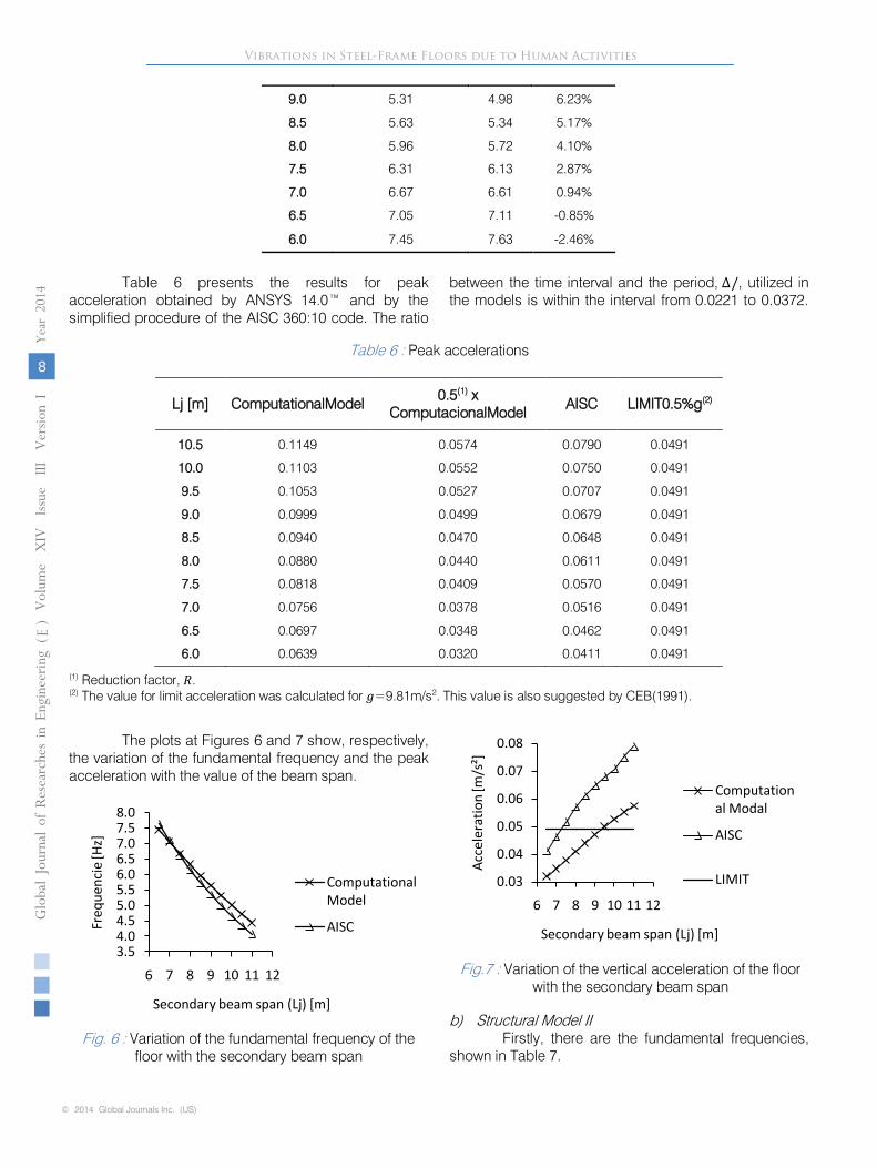
Table 6 presents the results for peak acceleration obtained by ANSYS 14.0™ and by the simplified procedure of the AISC 360:10 code. The ratio
between the time interval and the period, Δ/, utilized in the models is within the interval from 0.0221 to 0.0372.
Table 6 : Peak accelerations
Lj [m]
ComputationalModel
0.5(1)
x ComputacionalModel
AISC
LIMIT0.5%g(2)
10.5
0.1149
0.0574
0.0790
0.0491
10.0
0.1103
0.0552
0.0750
0.0491
9.5
0.1053
0.0527
0.0707
0.0491
9.0
0.0999
0.0499
0.0679
0.0491
8.5
0.0940
0.0470
0.0648
0.0491
8.0
0.0880
0.0440
0.0611
0.0491
7.5
0.0818
0.0409
0.0570
0.0491
7.0
0.0756
0.0378
0.0516
0.0491
6.5
0.0697
0.0348
0.0462
0.0491
6.0 0.0639
0.0320
0.0411
0.0491
(1)
Reduction factor, 𝑃𝑃. (2)
The value for limit acceleration was calculated for 𝑔𝑔=9.81m/s2. This value is also suggested by CEB(1991).
The plots at Figures 6 and 7 show, respectively, the variation of the fundamental frequency and the peak acceleration with the value of the beam span.
3.54.04.55.05.56.06.57.07.58.0
6 7 8 9 10 11 12
Freq
uenc
ie [H
z]
Secondary beam span (Lj) [m]
Computational Model
AISC
0.03
0.04
0.05
0.06
0.07
0.08
6 7 8 9 10 11 12
Acce
ler a
ti on
[ m/ s
²]
Secondary beam span (Lj) [m]
Computational Modal
AISC
LIMIT
Vibrations in Steel-Frame Floors due to Human Activities
© 2014 Global Journals Inc. (US)
Globa
l Jo
urna
l of
Resea
rche
s in E
nginee
ring
()
Volum
e X
IV
Iss u
e III
Version
I
Year
2014
8
E
Fig. 6 : Variation of the fundamental frequency of the floor with the secondary beam span
b) Structural Model IIFirstly, there are the fundamental frequencies,
shown in Table 7.
Fig.7 : Variation of the vertical acceleration of the floor with the secondary beam span
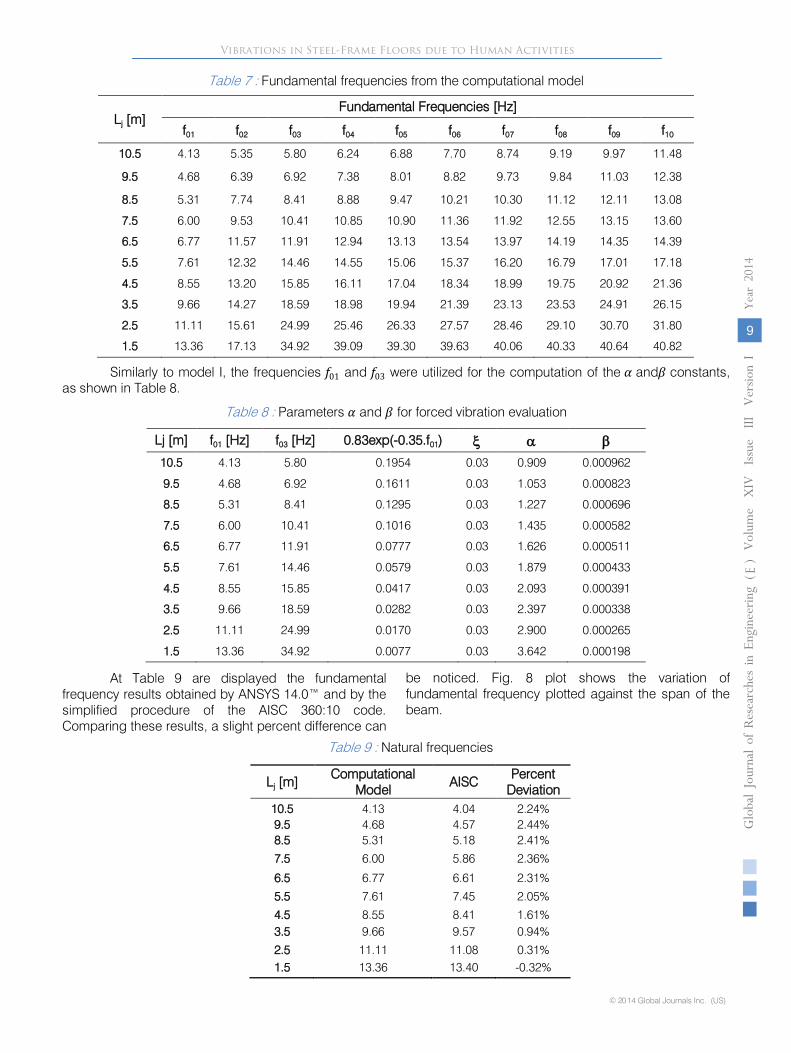
Table 7 : Fundamental frequencies from the computational model
Lj [m] Fundamental Frequencies [Hz]
f01 f02 f03 f04 f05 f06 f07 f08 f09 f10
10.5 4.13 5.35 5.80 6.24 6.88 7.70 8.74 9.19 9.97 11.48
9.5 4.68 6.39 6.92 7.38 8.01 8.82 9.73 9.84 11.03 12.38
8.5 5.31 7.74 8.41 8.88 9.47 10.21 10.30 11.12 12.11 13.08
7.5 6.00 9.53 10.41 10.85 10.90 11.36 11.92 12.55 13.15 13.60
6.5 6.77 11.57 11.91 12.94 13.13 13.54 13.97 14.19 14.35 14.39
5.5 7.61 12.32 14.46 14.55 15.06 15.37 16.20 16.79 17.01 17.18
4.5 8.55 13.20 15.85 16.11 17.04 18.34 18.99 19.75 20.92 21.36
3.5 9.66 14.27 18.59 18.98 19.94 21.39 23.13 23.53 24.91 26.15
2.5 11.11 15.61 24.99 25.46 26.33 27.57 28.46 29.10 30.70 31.80
1.5 13.36 17.13 34.92 39.09 39.30 39.63 40.06 40.33 40.64 40.82
Similarly to model I, the frequencies 𝑓𝑓01
and 𝑓𝑓03
were utilized for the computation of the 𝛼𝛼
and𝛽𝛽
constants, as shown in Table 8.
Table 8
: Parameters 𝛼𝛼
and 𝛽𝛽
for forced vibration evaluation
Lj [m]
f01
[Hz]
f03
[Hz]
0.83exp(-0.35.f01) ξ α β 10.5 4.13
5.80
0.1954
0.03
0.909
0.000962
9.5
4.68
6.92
0.1611
0.03
1.053
0.000823
8.5 5.31
8.41
0.1295
0.03
1.227
0.000696
7.5
6.00
10.41
0.1016
0.03
1.435
0.000582
6.5 6.77
11.91
0.0777
0.03
1.626
0.000511
5.5
7.61
14.46
0.0579
0.03
1.879
0.000433
4.5 8.55
15.85
0.0417
0.03
2.093
0.000391
3.5
9.66
18.59
0.0282
0.03
2.397
0.000338
2.5 11.11
24.99
0.0170
0.03
2.900
0.000265
1.5
13.36
34.92
0.0077
0.03
3.642
0.000198
At Table 9 are displayed the fundamental
frequency results obtained by ANSYS 14.0™ and by the simplified procedure of the AISC 360:10 code. Comparing these results, a slight percent difference can
Table 9
: Natural frequencies
Lj
[m]
Computational Model
AISC
Percent Deviation
10.5
4.13
4.04
2.24%
9.5
4.68
4.57
2.44%
8.5
5.31
5.18
2.41%
7.5
6.00
5.86
2.36%
6.5
6.77
6.61
2.31%
5.5
7.61
7.45
2.05%
4.5
8.55
8.41
1.61%
3.5
9.66
9.57
0.94%
2.5
11.11
11.08
0.31%
1.5
13.36
13.40
-0.32%
Vibrations in Steel-Frame Floors due to Human Activities
© 2014 Global Journals Inc. (US)
Globa
l Jo
urna
l of
Resea
rche
s in E
nginee
ring
()
Volum
e X
IV
Issu
e III
Version
I
9
Year
2014
E
be noticed. Fig. 8 plot shows the variation of fundamental frequency plotted against the span of the beam.
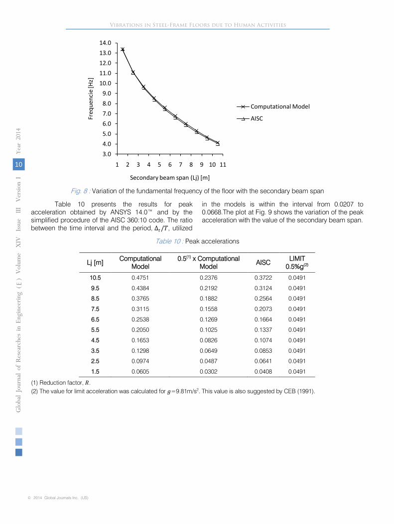
Fig. 8 : Variation of the fundamental frequency of the floor with the secondary beam span
Table 10 presents the results for peak
acceleration obtained by ANSYS
14.0™ and by the simplified procedure of the AISC 360:10 code. The ratio between the time interval and the period, Δ𝑡𝑡/𝑇𝑇, utilized
in the models is within the interval from 0.0207 to 0.0668.The plot at Fig. 9 shows the variation of the peak acceleration with the value of the secondary beam span.
Table 10 : Peak accelerations
Lj [m] Computational
Model 0.5(1) x Computational
Model AISC
LIMIT 0.5%g(2)
10.5 0.4751 0.2376 0.3722 0.0491
9.5 0.4384 0.2192 0.3124 0.0491
8.5 0.3765 0.1882 0.2564 0.0491
7.5 0.3115 0.1558 0.2073 0.0491
6.5 0.2538 0.1269 0.1664 0.0491
5.5 0.2050 0.1025 0.1337 0.0491
4.5 0.1653 0.0826 0.1074 0.0491
3.5 0.1298 0.0649 0.0853 0.0491
2.5 0.0974 0.0487 0.0641 0.0491
1.5 0.0605 0.0302 0.0408 0.0491
(1) Reduction factor, 𝑃𝑃. (2) The value for limit acceleration was calculated for 𝑔𝑔=9.81m/s2. This value is also suggested by CEB (1991).
3.04.05.06.07.08.09.0
10.011.012.013.014.0
1 2 3 4 5 6 7 8 9 10 11
Freq
uenc
ie [H
z]
Secondary beam span (Lj) [m]
Computational Model
AISC
Vibrations in Steel-Frame Floors due to Human Activities
© 2014 Global Journals Inc. (US)
Globa
l Jo
urna
l of
Resea
rche
s in E
nginee
ring
()
Volum
e X
IV
Iss u
e III
Version
I
Year
2014
10
E
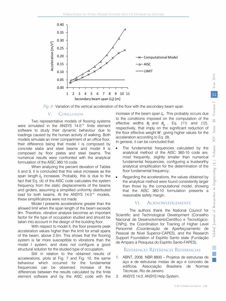
Fig.
9 : Variation of the vertical acceleration of the floor with the secondary beam span
V.
CONCLUSION
Two representative models of flooring systems were simulated in the ANSYS 14.0™ finite element software to study their dynamic behaviour due to loadings caused by the human activity of walking. Both models simulate an inner compartment of an office floor, their difference being that model I is composed by concrete slabs and steel beams and model II is composed by floor plates and steel beams. The numerical results were confronted with the analytical formulation of the AISC 360:10 code.
When analyzing the percent deviation of Tables
5 and 9, it is concluded that this value increases as the span length 𝐿𝐿𝑗𝑗
increases. Probably, this is due to the fact that Eq. (4) of the AISC code calculates the system frequency from the static displacements of the beams and girders, assuming a simplified uniformly distributed load for both beams. At the ANSYS 14.0™ models, these simplifications were not made.
Model I presents accelerations greater than the
allowed limit when the span length of the beam exceeds 9m. Therefore, vibration analysis becomes an important factor for the type of occupation studied and should be taken into account in the design of the building floor.
With respect to model II, the floor presents peak
acceleration values higher than the limit for small spans of the beam, above 2.5m. This shows that the flooring system is far more susceptible to vibrations than the model I system, and does not configure a good structural solution for the studied type of occupation.
Still in relation to the obtained results of
accelerations, plots at Fig. 7 and Fig. 10, the same behaviour which occurred for the fundamental frequencies can be observed: increase of the differences between the results calculated by the finite element software and by the AISC code with the
increase of the beam span 𝐿𝐿𝑗𝑗 . This probably occurs due to the conditions imposed on the computation of the effective widths 𝜔𝜔𝑗𝑗 and 𝜔𝜔𝑔𝑔 , Eq. (11) and (12), respectively, that imply on the significant reduction of the floor effective weight 𝛽𝛽, giving higher values for the acceleration according to Eq. (9).
In general, it can be concluded that:
•
The fundamental frequencies calculated by the analytical method of the AISC 360-10 code are, most frequently, slightly smaller than numerical fundamental frequencies, configuring a trustworthy analytical simplification for the determination of the floor fundamental frequency;
•
Regarding the accelerations, the values obtained by the analytical method were found consistently larger than those by the computational model, showing that the AISC 360-10 formulation presents a reasonable safety margin.
VI.
Acknowledgements
The authors thank the National Council for Scientific and Technological Development (Conselho
Nacional de DesenvolvimentoCientífico e Tecnológico-CNPq), the Coordination for Training of Higher Level
Personnel (Coordenação de Aperfeiçoamento de Pessoal de Nível Superior-CAPES), and the Research Support Foundation of Espírito Santo state (Fundação de Amparo à Pesquisa do Espírito Santo-FAPES).
References Références Referencias
1.
ABNT, 2008. NBR 8800 – Projetos de estruturas de aço e de estruturas mistas de aço e concreto de
0.00
0.05
0.10
0.15
0.20
0.25
0.30
0.35
0.40
1 2 3 4 5 6 7 8 9 10 11
Acce
lera
t ion
[m/s
²]
Secondary beam span (Lj) [m]
Computational Model
AISC
LIMIT
Vibrations in Steel-Frame Floors due to Human Activities
© 2014 Global Journals Inc. (US)
Globa
l Jo
urna
l of
Resea
rche
s in E
nginee
ring
()
Volum
e X
IV
Issu
e III
Version
I
11
Year
2014
E
edifícios. Associação Brasileira de Normas Técnicas, Rio de Janeiro.
2. ANSYS 14.0. ANSYS Help System.
3.
Bathe, K. J., 1996. Finite Element Procedures. New Jersey.
4.
CEB, 1991. Vibrations Problems in Structures – Practical Guidelines. Bulletin d’information nº
209. Comité Euro-International du Béton, Lausanne.
5.
Clough, W. R., Penzien, J., 1995. Dynamics of Structures. Berkeley.
6.
Mello, A. V. de A., 2005. Vibrações em pisos de edificações induzidas por atividades humanas. Dissertação de Mestrado, Universidade do Estado do Rio de Janeiro.
7.
Murray, T. M., Allen, D. E. &
Ungar, E. E., 2003. Floor Vibrations Due to Human Activity. Steel design guide series 11, American Institute of Steel Construction, Chicago; Canadian Institute of Steel Construction, Toronto.
8.
Pretti, L. A., 2012. Vibrações em pavimentos de edifícios originadas pelas ações humanas. Dissertação de Mestrado, Universidade Federal doEspírito Santo.
Vibrations in Steel-Frame Floors due to Human Activities
© 2014 Global Journals Inc. (US)
Globa
l Jo
urna
l of
Resea
rche
s in E
nginee
ring
()
Volum
e X
IV
Iss u
e III
Version
I
Year
2014
12
E