Embed Size (px)
Citation preview

1. Introduction
High-speed trains as efficient and economical
transportation tools have developed rapidly in the past
decade. However, increasing train speed results in serious
vibrations, which exert adverse effects on ride stability and
quality. Therefore, vibration suppression in high-speed trains
has become a crucial and challenging issue. Various control
techniques for train suspension systems have been proposed
to improve ride comfort and safety, and these techniques can
be classified as passive, active, and semi-active. Passive
control techniques possess relatively high reliability,
robustness, and practicability, but their control performance
is often limited because they cannot adapt to a wide
frequency range of excitations induced by rail track
irregularities.
Active control techniques can produce favorable control
forces through actuators and exhibit high vibration
suppression performance over a broad frequency range of
excitations. Therefore, train suspensions have been
investigated with various active control techniques
(Yoshimura et al., 1993; Sasaki et al., 1994; Shimamune and
Tanifuji, 1995; Pratt and Goodall, 1997; Goodall, 1997;
Pearson et al., 1998; Tanifuji, 1998; Bruni and Resta, 2001;
Goodall and Kortüm, 2002; Tanifuji et al., 2002; Peiffer et
al., 2004; He and McPhee, 2005; Bruni et al., 2007; Orukpe
et al., 2008; Mellado et al., 2009; Zhou et al., 2010; Orvnäs
et al., 2011; Li et al., 2015). Active control requires a
Corresponding author, Associate Professor
E-mail: [email protected] a Research Associate
complicated system that involves sensors, actuators,
controllers, external power supplies, and high initial and
maintenance costs. Any measurement noise from sensors or
power outage adversely affects control performance.
Meanwhile, semi-active control techniques based on
magnetorheological (MR) dampers have been developed for
train suspensions because their performance is better than
that of passive control techniques, and their power
requirement and cost are lower than those of active control
techniques. Representative control strategies include
skyhook control (O'Neill and Wale, 1994), neuro-fuzzy
control (Atray and Roschke, 2004), adaptive fuzzy control
(Yang et al., 2006), linear quadratic Gaussian (LQG) control
(Liao and Wang, 2003; Wang and Liao, 2009a; b), and H∞
control (Zong et al., 2013). Moreover, Li et al. (2013)
proposed a viscoelastic model of MR dampers and applied it
in a high-speed train. Ni et al. (2016) tested the performance
of MR dampers on a full-scale high-speed train. However,
semi-active MR dampers can only provide control forces in
the opposite direction of damper velocity and thus cannot
fully identify the force–displacement relationship
determined by active control strategies.
Several studies on active control have revealed that the
linear quadratic regulator (LQR) algorithm, a commonly
adopted optimal control theory for active dampers, may
produce a damper force–displacement relationship with an
apparent negative stiffness feature that benefits vibration
control performance (Iemura and Pradono, 2005). Therefore,
the negative stiffness concept has been increasingly applied
b Associate Professor
c Professor
Vibration Suppression in High-speed Trains with Negative Stiffness Dampers
Xiang SHI1, 2,a, Songye ZHU 2,b, Yi-qing NI2,c, Jianchun Li3,c
1 College of Information and Control Engineering, China University of Petroleum (East China), Qingdao, Shandong Province, China 2 Department of Civil and Environmental Engineering, National Rail Transit Electrification and Automation Engineering Technology Research
Center (Hong Kong Branch), The Hong Kong Polytechnic University, Hung Hom, Kowloon, Hong Kong 3 Centre for Built Infrastructure Research, Faculty of Engineering and Information Technology, University of Technology Sydney, NSW,
Australia * Corresponding author: [email protected]
(Received keep as blank , Revised keep as blank , Accepted keep as blank )
Abstract. This work proposes and investigates re-centering negative stiffness dampers (NSDs) for vibration suppression in
high-speed trains. The merit of the negative stiffness feature is demonstrated by active controllers on a high-speed train. This merit
inspires the replacement of active controllers with re-centering NSDs, which are more reliable and robust than active controllers.
The proposed damper design consists of a passive magnetic negative stiffness spring and a semi-active positioning shaft for re-
centering function. The former produces negative stiffness control forces, and the latter prevents the amplification of quasi-static
spring deflection. Numerical investigations verify that the proposed re-centering NSD can improve ride comfort significantly
without amplifying spring deflection.
Keywords: negative stiffness, vibration control, high-speed train, active control, re-centering

Xiang SHI, Songye ZHU and Yi-qing NI
in vibration control for different mechanical and civil
structures, including high-speed trains (Lee and
Goverdovskiy, 2012; Lee et al., 2016), vehicle seats (Lee et
al., 2007; Le and Ahn, 2011), isolation tables (Platus and
Ferry, 2007; Yang, 2013;), adjustable constant force systems
(Liu et al., 2016), tunable stiffness systems (Churchill et al.,
2016), buildings (Asai et al., 2013; Iemura et al., 2006;
Iemura and Pradono, 2009; Pasala et al., 2012; Sun et al.,
2017), stay cables (Li et al., 2008; Weber and Boston, 2011,
Shi et al., 2016; 2017; Balch et al., 2017), and cable-stayed
bridges (Iemura and Pradono, 2002).
Inspired by these findings, various negative stiffness
dampers (NSDs) have been developed through semi-active
(Iemura and Pradono 2002, Iemura et. al. 2006; Høgsberg,
2011; Weber et al., 2011) or passive (Dijkstra et al. 1988; Lee
et al. 2007; Iemura and Pradono, 2009; Pasala et al., 2012;
Kalathur and Lakes, 2013; Cortes et. al., 2017) means. For
example, Shi and Zhu (2015, 2017) recently proposed two
passive designs of magnetic NSDs (MNSDs) that efficiently
integrate the magnetic negative-stiffness mechanism and
eddy-current damping in compact cylindrical configurations
and developed corresponding optimal design methods.
Passive or semi-active NSDs demonstrate superior control
performance that is comparable to that of active controllers
and are thus promising control strategies that present high
performance and good reliability and practicability.
The feasibility of applying the negative stiffness
mechanism in high-speed trains to improve ride comfort has
also been investigated. To increase isolation efficiency at a
low frequency range, which is harmful to humans, Lee and
Goverdovskiy (2012) designed geometrically similar
redundant mechanisms with negative stiffness that can be
inserted into multi-stages of high-speed rails, including
vehicle seats, bogies, and track beds. The effectiveness of
their design was verified using vehicle seats (Lee and
Goverdovskiy, 2012) and train bogies (Lee et al., 2016).
Another study discovered that a decreasing suspension
stiffness value may increase the critical speed of high-speed
trains (Sun et al., 2013). A negative-stiffness spring is an
efficient means to decrease suspension stiffness without
compromising the carrying capacity. However, the
effectiveness of NSDs in high-speed train suspensions has
not been systematically examined. This work presents the
benefits of negative stiffness behavior in vibration control for
high-speed trains. Numerical simulations of active
controllers in high-speed trains reveal a control force–
displacement relationship with an apparent negative stiffness
feature. Subsequently, a re-centering NSD is proposed and
analyzed in parallel with train suspensions. The proposed
NSD consists of a passive magnetic negative stiffness spring
and a semi-active positioning shaft with a re-centering
function. Numerical simulation results in different conditions
indicate that the re-centering NSD can improve ride comfort
effectively and prevent the amplification of suspension
deflection. As low-bandwidth control strategies, re-centering
NSDs are a simple and promising alternative to conventional
active controllers.
2. Simulation of High-speed Trains
2.1 Dynamic Model of High-speed Trains
The model with 17 degrees of freedom (DOF) for high-
speed trains proposed by Zong et al. (2013) is adopted for
numerical simulations in this study. Fig. 1 shows the
analytical model of a high-speed train with dampers. The
high-speed train model in the figure is composed of one car
body, two bogies, and four wheelsets. The car body is
connected to the leading and rear bogies by secondary
suspensions, and each bogie is connected to two wheelsets
by primary suspensions (Zong et al., 2013). The dampers are
installed in the secondary suspensions in the lateral direction
because secondary lateral damping is the most critical
element of a car body in terms of vibration suppression (Sun
et al. 2013). As shown in Fig. 1, four dampers are installed;
two of them symmetrically connect the car body and leading
bogie, and the other two connect the car body and rear bogie.
Table 1 lists the 17 DOFs considered in the high-speed train
model, and the corresponding governing equations are
briefly described in the Appendix.
The governing equations of the 17-DOF model can be
expressed in the following matrix form.
u wMq + Cq + Kq = F u + F w (1)
where M, C, and K are the mass, damping, and stiffness
matrices of a high-speed train, respectively; Fu is the
coefficient matrix related to the locations of dampers or
control devices; Fw is the excitation matrix due to track
irregularities; and q is the vector containing all the DOFs of
the train model.
1 1 1 2 2 2
1 1 2 2 3 3 4 4
, ...
...
c c c t t t t t t
w w w w w w w w
y y y
y y y y
T
q = (2)
The vector of the control forces, u, is expressed as
follows:
1 2u uT
u (3)
where u1 and u2 are the control forces between the car body
and leading bogie and between the car body and rear bogie,
respectively. Each represents the resultant forces of the two
symmetrically installed dampers.
w=[w1 w2]T is the vector of track irregularities that excite
the wheels, and w1 and w2 are track irregularities in lateral
alignment (ya) and cross level (θcl). They are defined as
1 1 2 3 4 1 2 3 4
2 1 2 3 4 1 2 3 4
a a a a cl cl cl cl
a a a a cl cl cl cl
y y y y
y y y y
T
T
w
w
(4)
The calculation of lateral alignment and cross level is
explained in detail in the next section.
The governing equations can be rewritten into a state
space form as
c wz = Az + B u + B w (5)
where z is the state vector,
qz =
q (6)
A is the state matrix,

Vibration Suppression in High-speed Trains with Negative Stiffness Dampers
-1 -1
0 IA
-M K -M C (7)
Fig. 1 Analytical model of a high-speed train with dampers (Zong et al., 2013)
Table 1 Lateral motions of the 17-DOF high-speed train model (Zong et al., 2013)
Component
Motion
Lateral Yaw Roll
Car body yc φc θc
Bogie Leading bogie yt1 φt1 θt1
Rear bogie yt2 φt2 θt2
Wheelset Leading bogie leading wheelset yw1 φw1
Leading bogie trailing wheelset yw2 φw2
Rear bogie leading wheelset yw3 φw3
Rear bogie trailing wheelset yw4 φw4
xc
zc
yc
θc
θt1
xc
yc
φc
yt2
φt2
yw
4
φw
4
yw
3
φw
3
yt1
φt1
yw
2
φw
2
yw
1
φw
1
Dam
per
Prim
ary su
spen
sion
Seco
ndary
susp
ensio
n
Car b
ody
Bogie
Wheelset

Bw is the input matrix for track irregularities,
w 1
w
0B
M F (8)
and Bc is the input matrix for the damper forces,
c -1
u
0B =
M F (9)
2.2 Track Irregularities
The vibrations of high-speed trains are mainly excited by
geometrical irregularities of tracks. A simulation approach
for track irregularities was established by Zong et al. (2013).
Track irregularities occur in the vertical profile, cross level,
lateral alignment, and gauge. The irregularities in lateral
alignment and cross level are the main causes of the lateral
vibrations of high-speed trains, and these two regularities can
be calculated as (Garivaltis et al., 1980; Bhatti and Garg,
1984)
2
l ra
y yy
,
2
l rcl
z z
b
(10)
where ly and ry are the lateral track irregularities of the
left and right rails, respectively; lz and rz are the vertical
track irregularities of the left and right rails, respectively; and
b is half of the reference distance between the rails.
Track irregularities can be typically described by the
power spectral densities (PSDs) of measurement data.
According to Claus and Schiehlen (1998), the one-sided PSD
functions of lateral alignment and cross level are given by
2
2 2 2 2
2 2 2
2 2 2 2 2 2
a ca
r c
v c
c
r c s
AS
A bS
(11)
where Ω is the spatial frequency (rad/m); Ωc, Ωr, and Ωs are
the truncated wavenumbers (rad/m); and Aa and Av are two
scalar factors of track irregularities.
Track irregularities in the time domain can be converted
from PSD functions using the method proposed by Chen and
Zhai (1999). Fig. 2 and Fig. 3 show the simulated track
irregularities in the lateral alignment and cross level,
(a) Time history (b) PSD
Fig. 2 Lateral alignment of track irregularity
(a) Time history (b) PSD
Fig. 3 Cross level of track irregularity
0 2 4 6 8 10-15
-10
-5
0
5
10
15
Time (s)
late
ral ali
gh
nm
en
t (m
m)
1 1010
-8
10-6
10-4
10-2
Frequency (Hz)
PS
D (
m2/s
3)
0 2 4 6 8 10-15
-10
-5
0
5
10
15
Time (s)
late
ral ali
gh
nm
en
t (m
m)
1 1010
-8
10-6
10-4
10-2
Frequency (Hz)
PS
D (
m2/s
3)
0 2 4 6 8 10-5
0
5
Time (s)
Cro
ss lev
el (m
m)
1 1010
-8
10-7
10-6
10-5
Frequency (Hz)
PS
D (
m2/s
3)
0 2 4 6 8 10-5
0
5
Time (s)
Cro
ss lev
el (m
m)
1 1010
-8
10-7
10-6
10-5
Frequency (Hz)
PS
D (
m2/s
3)

Vibration Suppression in High-speed Trains with Negative Stiffness Dampers
respectively. Fig. 2(a) and Fig. 3 (a) present the time
histories, and Fig. 2(b) and Fig. 3(b) present the
corresponding PSDs.
2.3 Curved Track
When a high-speed train travels on a curved track, the car
body moves laterally due to a centrifugal force. Fig. 4(a)
presents the geometric curvature of a curved track with a
radius of 3200 m. The transition segment from a straight
track to a circular one is 200 m long. When a high-speed train
passes the curved track at 300 km/h, the corresponding
centripetal acceleration is shown in Fig. 4(b).
3. Negative Stiffness in Active Control To verify the benefits of negative stiffness, the force–
displacement relationship of the LQR controller for high-
speed trains is investigated in this section.
The control forces of LQR controllers can be calculated
as
lqr lqru = -G z (12)
where Glqr is the optimal feedback gain that minimizes
quadratic performance index J.
0
TJ dt
T
lqr lqrz Qz u Ru (13)
(a) Track geometry
(b) Centripetal acceleration
Fig. 4 Curved track with a radius of 3,200 m
0 200 400 600 8000
1
2
3
4x 10
-4
Distance (m)
Curv
atu
re (
1/m
)
Circular curveTransitionStraight
0 2 4 6 8 100
0.5
1
1.5
2
2.5
Time (s)
cen
trip
eta
l accel
era
tio
n (
m/s
2)

Xiang SHI, Songye ZHU and Yi-qing NI
where Q and R are symmetric positive-definite matrices.
Consequently, feedback gain Glqr can be determined as 1
lqr
Tc
G R B P (14)
where P should satisfy the reduced-matrix Riccati equation 1T T
c cA P PA PB R B P Q 0 (15)
By substituting Eq. (12) into Eq. (5), the state space
equation of a high-speed train with LQR controllers can be
expressed as
c lqr w
z A B G z B w (16)
The performance of the LQR controller is determined by
the Q and R matrices. Given that ride comfort is the focus of
this work, the elements corresponding to car body vibration
should be significantly larger than the rest. Given a Q matrix,
the performance of the LQR controller can be manipulated
by adjusting the R value. The control energy of the LQR
controller generally increases as the R value decreases.
When a high-speed train with an LQR controller travels
on a straight track at 300 km/h, its dynamic responses can be
calculated from the state space model. The responses of the
high-speed train with a passive damper (viscous damping: 52
kNs/m) are also calculated for reference. Fig. 5 and Fig. 6
(a) Lateral accelerations (a) Lateral accelerations
(b) Yaw accelerations (b) Yaw accelerations
(c) Roll accelerations (c) Roll accelerations
Fig. 5 Time history of car body accelerations under
random track irregularities
Fig. 6 PSD of car body accelerations under random track
irregularities
Vibration Suppression in High-speed Trains with Negative Stiffness Dampers
present the car body responses in time and frequency
domains, respectively.
The performance of the LQR controller is generally much
better than that of the passive damper, and the performance
of the LQR controller improves as R decreases. When the
train is protected by a passive damper, the root mean square
(RMS) values of car body accelerations in the lateral, yaw,
and roll directions are 0.381 m/s2, 0.0499 rad/s2, and 0.146
rad/s2, respectively; when the LQR controller (R = I × 10-6)
is adopted, the RMS values of car body accelerations in the
lateral, yaw, and roll directions decrease to 0.176 m/s2,
0.0225 rad/s2, and 0.0755 rad/s2, respectively. If R = I × 10-
8, the RMS values in the lateral, yaw, and roll directions
decrease to 0.0661 m/s2, 0.0215 rad/s2, and 0.0350 rad/s2,
respectively. If R is further decreased to I × 10-10, the RMS
values of car body accelerations in the lateral, yaw, and roll
directions can be further reduced to 0.00193 m/s2, 0.00211
rad/s2, and 0.00441 rad/s2, respectively (Fig. 5(a), 5(b), and
5(c)). Similar conclusions can also be drawn from the car
body response in the frequency domain. As shown in Fig.
6(a), 6(b), and 6(c), the peak responses of PSD in the lateral,
yaw, and roll directions decrease as the R value of the LQR
controller decreases.
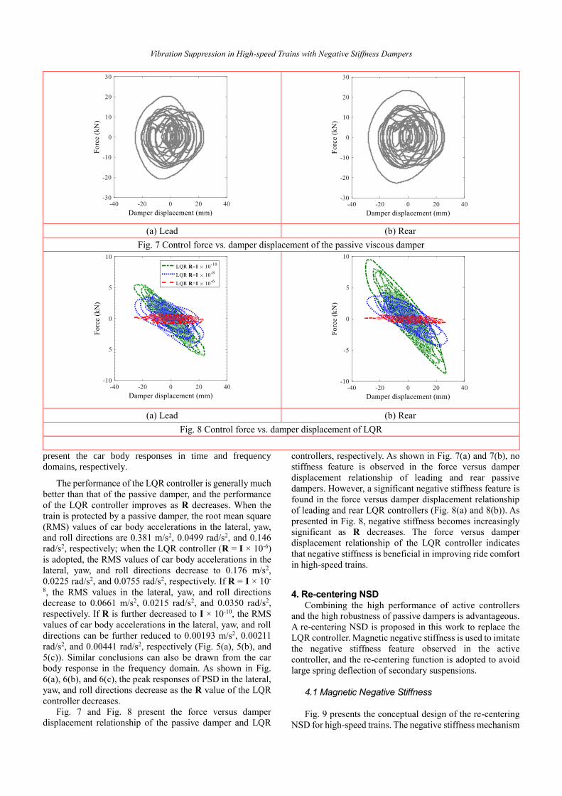
Fig. 7 and Fig. 8 present the force versus damper
displacement relationship of the passive damper and LQR
controllers, respectively. As shown in Fig. 7(a) and 7(b), no
stiffness feature is observed in the force versus damper
displacement relationship of leading and rear passive
dampers. However, a significant negative stiffness feature is
found in the force versus damper displacement relationship
of leading and rear LQR controllers (Fig. 8(a) and 8(b)). As
presented in Fig. 8, negative stiffness becomes increasingly
significant as R decreases. The force versus damper
displacement relationship of the LQR controller indicates
that negative stiffness is beneficial in improving ride comfort
in high-speed trains.
4. Re-centering NSD
Combining the high performance of active controllers
and the high robustness of passive dampers is advantageous.
A re-centering NSD is proposed in this work to replace the
LQR controller. Magnetic negative stiffness is used to imitate
the negative stiffness feature observed in the active
controller, and the re-centering function is adopted to avoid
large spring deflection of secondary suspensions.
4.1 Magnetic Negative Stiffness
Fig. 9 presents the conceptual design of the re-centering
NSD for high-speed trains. The negative stiffness mechanism
(a) Lead (b) Rear
Fig. 7 Control force vs. damper displacement of the passive viscous damper
(a) Lead (b) Rear
Fig. 8 Control force vs. damper displacement of LQR

Xiang SHI, Songye ZHU and Yi-qing NI
of the proposed damper follows the principle of Design B
MNSD (Shi and Zhu, 2015). The damper consists of one
repositioning shaft and two magnets (one outer static magnet
ring and one inner moving magnet cylinder with the same
pole orientation). As shown in Fig. 10, when the two magnets
are concentric, the moving magnet is at zero damper
displacement. When the inner moving magnet moves away
from the zero position, the repelling force between the two
magnets is counterbalanced by an external force in the
opposite direction of the displacement, which induces
negative stiffness behavior (Shi and Zhu, 2015). The detailed
design and optimization method of MNSD were developed
by Shi and Zhu (2017).
Fig. 9 Re-centering negative stiffness damper
Fig. 10 Principle of negative stiffness
4.2 Re-centering Function
The re-centering function can prevent large spring
deflection when high-speed trains with NSD travels on
curved tracks. The re-centering function uses low-pass
filtered lateral accelerations as the reference signal. Such a
re-centering function belongs to low-bandwidth control
because the reference signal is utilized to detect the low-
frequency component of track inputs (e.g., curvature). A
similar low-bandwidth control method, namely, Hold-Off-
Device, has been implemented in high-speed trains (Allen,
1994; Orvnäs et al., 2010; 2011).
Fig. 11 shows the principle of the re-centering function in
high-speed trains. As shown in Fig. 11(a), when a high-speed
train travels on a straight track, its car body and bogie are
symmetric. However, when the train passes a curved track, a
quasi-static relative displacement (∆x) is generated by the
centripetal acceleration in the lateral direction (Fig. 11(b)).
This centripetal acceleration is measured by sensors with a
low-pass filter; then, the controller sends control signals to
actuators to re-center the damper (Fig. 11). If the re-
positioning shaft of the left NSD elongates (∆x) and the shaft
of the right NSD shortens (∆x), the relative position between
the dampers’ zero displacement and the centerline of the car
body will not change. The relative displacement between the
car body and bogie will not be amplified by the negative
stiffness because the quasi-static loads are carried by the
lateral stiffness of the train suspension. In practice, actuators
could be a linear motor, a rotary motor with a ball screw, or
a rotary motor with pinion and rack.
Aside from re-centering of NSD, HOD can also be
adopted to minimize spring deflection. HOD is used to center
the car body when a train travels on a curved track. As a
result, bump stop contact between the car body and bogie is
avoided. HOD was proposed by Allen (1994). Orvnäs et al.
(2010, 2011) verified the effectiveness of HOD numerically
and experimentally. In their implementation, the low-pass
filtered lateral acceleration from the leading bogie was used
as the reference signal, and this signal was multiplied by half
the car body mass to create an actuator force that counteracts
the lateral movement of the car body when a train travels on
a curved track.
5. Performance Evaluation
5.1 Evaluation Cases
In this section, the performance of the re-centering NSD
is evaluated with three different levels of negative stiffness.
The negative stiffness values considered are −105, −210, and
−315 kN/m, and each value represents the summation of the
negative stiffness values provided by two symmetrically
installed NSDs (Fig. 1). Therefore, each NSD is designed to
provide only half of the target negative stiffness. We follow
the design procedure developed by Shi and Zhu (2017), and
the designed magnet dimensions that satisfy the target values
are presented in Table 2.
5.2 Straight Track Performance
The performance of the re-centering NSD in high-speed
trains is evaluated numerically with the same model used in
the LQR controller analysis. Fig. 12 presents the response of
the car body when a high-speed train with re-centering NSD
travels on a straight track at 300 km/h. Three cases with
different negative stiffness and damping coefficient
combinations are evaluated (Case 1: kn = −315 kN/m, cn = 5.2
kNs/m; Case 2: kn = −216 kN/m, cn = 20.8 kNs/m; Case 1: kn
= −105 kN/m, cn = 36.4 kNs/m). Fig. 12(a), 12(b), and 12(c)
show the car body responses in the lateral, yaw, and roll
NS
NS
Moving magnet Static magnet
Fixing
spacer
Repositioning
shaft
-30 -20 -10 0 10 20 30-1000
-800
-600
-400
-200
0
200
400
600
800
1000
Displacement (mm)
Forc
e (
N)
F
X

Vibration Suppression in High-speed Trains with Negative Stiffness Dampers
directions, respectively. As shown in these figures, the
responses in all directions decrease as the strength of
negative stiffness increases. When the negative stiffness
increases from −105 kN/m to −315 kN/m, the peak car body
accelerations in the lateral, yaw, and roll directions decrease
from approximately 0.5 m/s2 to 0.02 m/s2, 0.1 m/s2 to 0.007
rad/s2, and 0.3 m/s2 to 0.017 rad/s2, respectively. Similar
conclusions are drawn from the car body response in the
frequency domain. As shown in Fig. 13(a), 13(b), and 13(c),
the peak responses of PSD in the lateral, yaw, and roll
directions decrease as the strength of the negative stiffness
increases.
Although the re-centering NSD reduces the car body
responses significantly, it does not affect the response of the
bogies and wheelset. Table 3 summarizes the RMS values of
train responses when the train is protected by a passive
damper, an LQR controller, and a re-centering NSD. Except
for the car body responses, the differences between the
bogies and wheelset responses of the three methods are
within 5%.
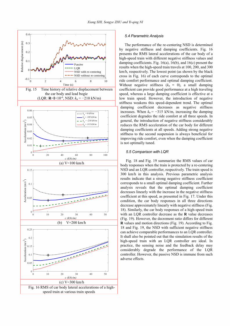
5.3 Curved Track Performance
The re-centering function ensures that the relative
displacements between the car body and bogie are not
amplified by negative stiffness. Fig. 15 presents the time
history of relative displacement between the car body and
leading bogie when a high-speed train travels on a curved
track whose geometry is presented in Fig. 4(a). As shown in
Fig. 15, all of the relative displacements of the train with a
passive damper, an LQR (R = I × 10-6) controller, and a re-
centering NSD (kn = –210 kN/m) are approximately 13 cm.
However, without the re-centering function, the relative
displacement is amplified by negative stiffness to 27 cm (Fig.
15).
(a) On a straight track (b) On a curved track
Fig. 11 Principle of the re-centering function
Table 2 Magnet dimension for three levels of negative stiffness
Case
No.
kn
(kN/m)
Static magnet Moving magnet
outer radius
(mm)
inner radius
(mm) thickness (mm) radius (mm) thickness (mm)
1 -315 40 31 80 30 80
2 -210 30 22 80 21 80
3 -105 20 11 80 10 80
Car body
Bogie
Car body
Bogie
∆x ∆x ∆x
Acceleration Signal
Low-pass filter
No adjustment of zero position
Low-pass filter
Re-center zero position
Acceleration Signal
Car body
Bogie
Car body
Bogie
∆x ∆x ∆x
Acceleration Signal
Low-pass filter
No adjustment of zero position
Low-pass filter
Re-center zero position
Acceleration Signal

Xiang SHI, Songye ZHU and Yi-qing NI
(a) Lateral accelerations (a) Lateral accelerations
(b) Yaw accelerations (b) Yaw accelerations
(c) Roll accelerations (c) Roll accelerations
Fig. 12 Time history of car body accelerations under
random track irregularities
Fig. 13 PSD of car body accelerations under random track
irregularities
Table 3 RMS of train response under various control methods
Motion
Control method
Passive LQR
R=I×10-10
NSD
kn=-315 kN/m
yc (m/s2) 0.380949 0.001928 0.019852
φc (rad/s2) 0.049875 0.00211 0.006941
θc (rad/s2) 0.146139 0.004414 0.016694
yt1 (m/s2) 2.32513 0.802757 1.580134
φt1 (rad/s2) 1.589666 1.11571 1.285941
θt1 (rad/s2) 0.286806 0.238034 0.213808
yt2 (m/s2) 2.446865 0.824441 1.589936
φt2 (rad/s2) 1.581386 1.112168 1.286246
θt2 (rad/s2) 0.283953 0.24519 0.211214
yw1 (m/s2) 8.772473 25.93056 8.883672
φw1 (rad/s2) 6.049266 4.049426 5.336823
yw2 (m/s2) 8.633698 25.92741 8.800308
φw2 (rad/s2) 6.324629 4.076435 5.446045
yw3 (m/s2) 8.813095 25.93089 8.88865
φw3 (rad/s2) 6.013354 4.024187 5.303934
yw4 (m/s2) 8.672533 25.92583 8.806349
φw4 (rad/s2) 6.239002 4.056737 5.391424

Vibration Suppression in High-speed Trains with Negative Stiffness Dampers
(a) Lead (b) Rear
Fig. 14 Control force vs. damper displacement of NSD
Xiang SHI, Songye ZHU and Yi-qing NI
5.4 Parametric Analysis
The performance of the re-centering NSD is determined
by negative stiffness and damping coefficients. Fig. 16
presents the RMS lateral accelerations of the car body of a
high-speed train with different negative stiffness values and
damping coefficients. Fig. 16(a), 16(b), and 16(c) present the
results when the high-speed train travels at 100, 200, and 300
km/h, respectively. The lowest point (as shown by the black
cross in Fig. 16) of each curve corresponds to the optimal
ride comfort performance and optimal damping coefficient.
Without negative stiffness (kn = 0), a small damping
coefficient can provide good performance at a high traveling
speed, whereas a large damping coefficient is effective at a
low train speed. However, the introduction of negative
stiffness weakens this speed-dependent trend. The optimal
damping coefficient decreases as negative stiffness
increases. When kn = −315 kN/m, increasing the damping
coefficient degrades the ride comfort at all three speeds. In
general, the introduction of negative stiffness considerably
reduces the RMS acceleration of the car body for different
damping coefficients at all speeds. Adding strong negative
stiffness to the second suspension is always beneficial for
improving ride comfort, even when the damping coefficient
is not optimally tuned.
5.5 Comparison with LQR
Fig. 18 and Fig. 19 summarize the RMS values of car
body responses when the train is protected by a re-centering
NSD and an LQR controller, respectively. The train speed is
300 km/h in this analysis. Previous parametric analysis
results indicate that a strong negative stiffness coefficient
corresponds to a small optimal damping coefficient. Further
analysis reveals that the optimal damping coefficient
decreases linearly with the increase in the negative stiffness
coefficient at this speed, as presented in Fig. 17. Under this
condition, the car body responses in all three directions
decrease approximately linearly with negative stiffness (Fig.
18). Similarly, the car body responses of a high-speed train
with an LQR controller decrease as the R value decreases
(Fig. 19). However, the decrement ratio differs for different
R values and motion directions (Fig. 19). According to Fig.
18 and Fig. 19, the NSD with sufficient negative stiffness
can achieve comparable performances to an LQR controller.
It shall also be pointed out that the simulation results of the
high-speed train with an LQR controller are ideal. In
practice, the sensing noise and the feedback delay may
considerably degrade the performance of the LQR
controller. However, the passive NSD is immune from such
adverse effects.
Fig. 15 Time history of relative displacement between
the car body and lead bogie
(LQR: R=I×10-6, NSD: kn = −210 kN/m)
(a) V=100 km/h
(b) V=200 km/h
(c) V=300 km/h
Fig. 16 RMS of car body lateral accelerations of a high-
speed train at various train speeds
0 2 4 6 8 10-0.1
0
0.1
0.2
0.3
0.4
Time (s)
Rel
ati
ve d
isp
lacem
en
t (m
)
Passive
LQR
NSD with re-centering
NSD without re-centering

Vibration Suppression in High-speed Trains with Negative Stiffness Dampers
Fig. 17 Optimal relationship between negative stiffness and damping coefficients
(a) Lateral accelerations (a) Lateral accelerations
(b) Yaw accelerations (b) Yaw accelerations
(c) Roll accelerations (c) Roll accelerations
Fig. 18 Car body response of a high-speed train with NSD at a
traveling speed of 300 km/h Fig. 19 Car body response of a high-speed train with an active
LQR controller at a traveling speed of 300 km/h

Xiang SHI, Songye ZHU and Yi-qing NI
6. Conclusion
This work evaluates the benefits of negative stiffness in the
vibration control of high-speed trains and proposes a re-
centering negative stiffness damper (NSD) for high-speed
train suspensions. The numerical simulations reveal that the
force–deformation relationship produced by active
controllers (LQR) in high-speed trains possesses an obvious
negative stiffness feature. As the control energy of the active
controller increases, the controllers’ performance improves,
and the negative stiffness feature in their hysteresis loop
becomes highly significant. To combine the high
performance of active controllers and excellent robustness of
passive dampers, a passive NSD with a re-centering function
is proposed. In the proposed damper, passive negative
stiffness is realized with a magnetic negative stiffness spring,
and the re-centering function is realized by using a
positioning shaft. The capability of NSD to improve ride
comfort significantly is verified numerically, and the re-
centering function can avoid large spring deflection when a
train travels on a curved track.
Acknowledgement
The authors are grateful for the financial support from the
Innovation and Technology Commission of the HKSAR
Government to the Hong Kong Branch of National Rail
Transit Electrification and Automation Engineering
Technology Research Center (Project No. 1-BBY5) and from
the Research Grants Council of Hong Kong through the GRF
grant (Project No. PolyU 152222/14E). The findings and
opinions expressed in this paper are solely those of the
authors and are not necessarily the views of sponsors.
References
Allen, D. H. (1994). Active bumpstop hold-off device. In Proc
IMechE Conference Railtech (Vol. 94).
Asai, T., Spencer, B. F., Iemura, H., & Chang, C. M. (2013). Nature
of seismic control force in acceleration feedback. Structural
Control and Health Monitoring, 20(5), 789-803.
Atray, V. S., & Roschke, P. N. (2004). Neuro‐Fuzzy Control of
Railcar Vibrations Using Semiactive Dampers. Computer‐Aided Civil and Infrastructure Engineering, 19(2), 81-92.
Balch, S. P., & Lakes, R. S. (2017). Lumped negative stiffness
damper for absorption of flexural waves in a rod. Smart Materials
and Structures, 26(4), 045022.
Braghin, F., Bruni, S., & Resta, F. (2006). Active yaw damper for
the improvement of railway vehicle stability and curving
performances: simulations and experimental results. Vehicle
System Dynamics, 44(11), 857-869.
Bruni, S., & Resta, F. (2001). Active control of railway vehicles to
avoid hunting instability. In Advanced Intelligent Mechatronics,
2001. Proceedings. 2001 IEEE/ASME International Conference
on (Vol. 1, pp. 231-236). IEEE.
Bruni, S., Goodall, R., Mei, T. X., & Tsunashima, H. (2007).
Control and monitoring for railway vehicle dynamics. Vehicle
System Dynamics, 45(7-8), 743-779.
Chen, G., & Zhai, W. (1999). Numerical simulation of the
stochastic process of railway track irregularities. Journal of
Southwest Jiaotong University, 34(2), 138-142.
Churchill, C. B., Shahan, D. W., Smith, S. P., Keefe, A. C., &
McKnight, G. P. (2016). Dynamically variable negative stiffness
structures. Science advances, 2(2), e1500778.
Claus, H., & Schiehlen, W. (1998). Modeling and simulation of
railway bogie structural vibrations. Vehicle System Dynamics,
29(S1), 538-552.
Cortes, S., Allison, J., Morris, C., Haberman, M. R., Seepersad, C.
C., & Kovar, D. (2017). Design, Manufacture, and Quasi-Static
Testing of Metallic Negative Stiffness Structures within a
Polymer Matrix. Experimental Mechanics, 1-9.
Dijkstra, K., Videc, B. P., & Huizinga, J. (1988). U.S. Patent No.
4,722,517. Washington, DC: U.S. Patent and Trademark Office.
Garivaltis, D. S., Garg, V. K., & D'souza, A. F. (1980). Dynamic
response of a six-axle locomotive to random track inputs. Vehicle
System Dynamics, 9(3), 117-147.
Goodall, R. (1997). Active railway suspensions: Implementation
status and technological trends. Vehicle System Dynamics, 28(2-
3), 87-117.
Goodall, R. M., & Kortüm, W. (2002). Mechatronic developments
for railway vehicles of the future. Control Engineering Practice,
10(8), 887-898.
He, Y., & McPhee, J. (2005). Multidisciplinary design optimization
of mechatronic vehicles with active suspensions. Journal of
Sound and Vibration, 283(1), 217-241.
Høgsberg, J. (2011). The role of negative stiffness in semi‐active
control of magneto‐rheological dampers. Structural Control
and Health Monitoring, 18(3), 289-304.
Iemura, H., & Pradono, M. H. (2002). Passive and semi‐active
seismic response control of a cable‐stayed bridge. Structural
Control and Health Monitoring, 9(3), 189-204.
Iemura, H., & Pradono, M. H. (2005). Simple algorithm for semi‐
active seismic response control of cable‐ stayed bridges.
Earthquake engineering & structural dynamics, 34(4‐5), 409-
423.
Iemura, H., Igarashi, A., Pradono, M. H., & Kalantari, A. (2006).
Negative stiffness friction damping for seismically isolated
structures. Structural control and health monitoring, 13(2‐3),
775-791.
Iemura, H., & Pradono, M. H. (2009). Advances in the development
of pseudo‐negative‐stiffness dampers for seismic response
control. Structural Control and Health Monitoring, 16(7‐8),
784-799.
Kalathur, H., & Lakes, R. S. (2013). Column dampers with negative
stiffness: high damping at small amplitude. Smart Materials and
Structures, 22(8), 084013.
Lee, C. M., Goverdovskiy, V. N., & Temnikov, A. I. (2007). Design
of springs with “negative” stiffness to improve vehicle driver
vibration isolation. Journal of Sound and Vibration, 302(4), 865-
874.
Le, T. D., & Ahn, K. K. (2011). A vibration isolation system in low
frequency excitation region using negative stiffness structure for
vehicle seat. Journal of Sound and Vibration, 330(26), 6311-
6335.
Lee, C. M., & Goverdovskiy, V. N. (2012). A multi-stage high-
speed railroad vibration isolation system with “negative”
stiffness. Journal of Sound and Vibration, 331(4), 914-921.
Lee, C. M., Goverdovskiy, V. N., Sim, C. S., & Lee, J. H. (2016).
Ride comfort of a high-speed train through the structural upgrade
of a bogie suspension. Journal of Sound and Vibration, 361, 99-
107.
Li, H., Liu, M., & Ou, J. (2008). Negative stiffness characteristics
of active and semi‐ active control systems for stay cables.
Structural Control and Health Monitoring, 15(2), 120-142.
Li, Z., Ni, Y. Q., Dai, H., & Ye, S. (2013). Viscoelastic plastic
continuous physical model of a magnetorheological damper
applied in the high speed train. Science China Technological
Sciences, 56(10), 2433-2446.
Li, D. Y., Song, Y. D., & Cai, W. C. (2015). Neuro-adaptive fault-
Vibration Suppression in High-speed Trains with Negative Stiffness Dampers
tolerant approach for active suspension control of high-speed
trains. IEEE Transactions on Intelligent Transportation Systems,
16(5), 2446-2456.
Liao, W. H., & Wang, D. H. (2003). Semiactive vibration control
of train suspension systems via magnetorheological dampers.
Journal of intelligent material systems and structures, 14(3),
161-172.
Liu, Y., Yu, D. P., & Yao, J. (2016). Design of an adjustable cam
based constant force mechanism. Mechanism and Machine
Theory, 103, 85-97.
Mellado, A. C., Casanueva, C., Vinolas, J., & Giménez, J. G. (2009).
A lateral active suspension for conventional railway bogies.
Vehicle System Dynamics, 47(1), 1-14.
Ni, Y. Q., Ye, S. Q., & Song, S. D. (2016). An experimental study
on constructing MR secondary suspension for high-speed trains
to improve lateral ride comfort. Smart Structures and Systems,
18(1), 53-74.
O'Neill, H. R., & Wale, G. D. (1994). Semi-active suspension
improves rail vehicle ride. Computing & Control Engineering
Journal, 5(4), 183-188.
Orukpe, P. E., Zheng, X., Jaimoukha, I. M., Zolotas, A. C., &
Goodall, R. M. (2008). Model predictive control based on mixed
ℋ2/ℋ∞ control approach for active vibration control of railway
vehicles. Vehicle System Dynamics, 46(S1), 151-160.
Orvnäs, A., Stichel, S., & Persson, R. (2010). Ride comfort
improvements in a high-speed train with active secondary
suspension. Journal of Mechanical Systems for Transportation
and Logistics, 3(1), 206-215.
Orvnäs, A., Stichel, S., & Persson, R. (2011). Active lateral
secondary suspension with H∞ control to improve ride comfort:
simulations on a full-scale model. Vehicle System Dynamics,
49(9), 1409-1422.
Pasala, D. T. R., Sarlis, A. A., Nagarajaiah, S., Reinhorn, A. M.,
Constantinou, M. C., & Taylor, D. (2012). Adaptive negative
stiffness: new structural modification approach for seismic
protection. Journal of Structural Engineering, 139(7), 1112-1123.
Pearson, J. T., Goodall, R. M., & Pratt, I. (1998). Control system
studies of an active anti-roll bar tilt system for railway vehicles.
Proceedings of the Institution of Mechanical Engineers, Part F:
Journal of Rail and Rapid Transit, 212(1), 43-60.
Peiffer, A., Storm, S., Röder, A., Maier, R., & Frank, P. G. (2004).
Active vibration control for high speed train bogies. Smart
materials and structures, 14(1), 1.
Platus, D. L., & Ferry, D. K. (2007). Negative-stiffness vibration
isolation improves reliability of nanoinstrumentation. Laser
Focus World, 43(10), 107.
Pratt, I., & Goodall, R. (1997, June). Controlling the ride quality of
the central portion of a high-speed railway vehicle. In American
Control Conference, 1997. Proceedings of the 1997 (Vol. 1, pp.
719-723). IEEE.
Sasaki, K., Kamoshita, S., & Enomoto, M. (1994, September). A
design and bench test of multi-modal active suspension of
railway vehicle. In Industrial Electronics, Control and
Instrumentation, 1994. IECON'94., 20th International
Conference on (Vol. 3, pp. 2011-2016). IEEE.
Shi, X., & Zhu, S. (2015). Magnetic negative stiffness dampers.
Smart Materials and Structures, 24(7), 072002.
Shi, X., Zhu, S., Li, J. Y., & Spencer Jr, B. F. (2016). Dynamic
behavior of stay cables with passive negative stiffness dampers.
Smart Materials and Structures, 25(7), 075044.
Shi, X., Zhu, S., & Spencer Jr, B. F. (2017). Experimental study on
passive negative stiffness damper for cable vibration mitigation,
Journal of Engineering Mechanics,143(9), 04017070.
Shi, X., & Zhu, S. (2017). Simulation and optimization of magnetic
negative stiffness dampers. Sensors and Actuators A: Physical.
259, 14-33.
Shimamune, R., & Tanifuji, K. (1995, July). Application of oil-
hydraulic actuator for active suspension of railway vehicle:
experimental study. In SICE'95. Proceedings of the 34th SICE
Annual Conference. International Session Papers (pp. 1335-
1340). IEEE.
Sun, S., Deng, H., Li, W., Du, H., Ni, Y. Q., Zhang, J., & Yang, J.
(2013). Improving the critical speeds of high-speed trains using
magnetorheological technology. Smart Materials and Structures,
22(11), 115012.
Sun, T., Lai, Z., Nagarajaiah, S., & Li, H. N. (2017). Negative
stiffness device for seismic protection of smart base isolated
benchmark building. Structural Control and Health Monitoring.
Tanifuji, K. (1998). A prediction of wheel/rail lateral force induced
by actively controlled suspension for high speed railway vehicles.
Vehicle System Dynamics, 29(S1), 367-379.
Tanifuji, K., Koizumi, S., & Shimamune, R. H. (2002).
Mechatronics in Japanese rail vehicles: active and semi-active
suspensions. Control Engineering Practice, 10(9), 999-1004.
Wang, D. H., & Liao, W. H. (2009a). Semi-active suspension
systems for railway vehicles using magnetorheological dampers.
Part I: system integration and modelling. Vehicle System
Dynamics, 47(11), 1305-1325.
Wang, D. H., & Liao, W. H. (2009b). Semi-active suspension
systems for railway vehicles using magnetorheological dampers.
Part II: simulation and analysis. Vehicle System Dynamics,
47(12), 1439-1471.
Weber, F., Boston, C., & Maślanka, M. (2010). An adaptive tuned
mass damper based on the emulation of positive and negative
stiffness with an MR damper. Smart Materials and Structures,
20(1), 015012.
Weber, F., & Boston, C. (2011). Clipped viscous damping with
negative stiffness for semi-active cable damping. Smart
Materials and Structures, 20(4), 045007.
Yang, J., Li, J., & Du, Y. (2006, August). Adaptive fuzzy control of
lateral semi-active suspension for high-speed railway vehicle. In
International Conference on Intelligent Computing (pp. 1104-
1115). Springer Berlin Heidelberg.
Yang, J., Xiong, Y. P., & Xing, J. T. (2013). Dynamics and power
flow behaviour of a nonlinear vibration isolation system with a
negative stiffness mechanism. Journal of sound and vibration,
332(1), 167-183.
Yoshimura, T., Edokoro, K., & Ananthanarayana, N. (1993). An
active suspension model for rail/vehicle systems with preview
and stochastic optimal control. Journal of sound and vibration,
166(3), 507-519.
Zhou, R., Zolotas, A., & Goodall, R. (2010, June). LQG control for
the integrated tilt and active lateral secondary suspension in high
speed railway vehicles. In Control and Automation (ICCA), 2010
8th IEEE International Conference on (pp. 16-21). IEEE.
Zong, L. H., Gong, X. L., Xuan, S. H., & Guo, C. Y. (2013). Semi-
active H∞ control of high-speed railway vehicle suspension with
magnetorheological dampers. Vehicle System Dynamics, 51(5),
600-626.

Xiang SHI, Songye ZHU and Yi-qing NI
Appendix The governing equations of the 17-DOF high-speed train
model developed by Zong et al. (2013) are briefly described
in this appendix.
Car body dynamics
2 1 1 3 1
2 2 1 5 1
2 1 2 3 2
2 2 2 5 2
1 2
c c y c c c t t
y c c c t t
y c c c t t
y c c c t t
M y K y l h y h
C y l h y h
K y l h y h
C y l h y h
u u
2 1 1 3 1
2 2 1 5 1
2 1 2 3 2
2 2 2 5 2
2 2
2 2 1 2 3 1
2 2
2 2 2 2 3 2
1 2
cz c y c c c t t
y c c c t t
y c c c t t
y c c c t t
x c t x c t
x c t x c t
J K l y l h y h
C l y l h y h
K l y l h y h
C l y l h y h
K b C b
K b C b
u l u l
2 1 1 1 3 1
2 2 2 1 5 1
2 1 1 2 3 2
2 2 2 2 5 2
2 2
2 2 1 2 3 1
2 2
2 2 2 2 3 1
1 2 2 2
cx c y c c c t t
y c c c t t
y c c c t t
y c c c t t
z c t z c t
z c t x c t
J K h y l h y h
C h y l h y h
K h y l h y h
C h y l h y h
K b C b
K b C b
u h u h
Bogie dynamics
1 2 1 1 3 1
2 2 1 5 1
1 1 1 1 4 1 1
1 1 1 1 4 1 1
1 1 1 1 4 1 2
1 1 1 1 4 1 2
1
t t y c c c t t
y c c c t t
y t t t w
y t t t w
y t t t w
y t t t w
M y K y l h y h
C y l h y h
K y l h y
C y l h y
K y l h y
C y l h y
u
2 2 1 2 3 2
2 2 2 5 2
1 2 1 2 4 2 3
1 2 1 2 4 2 3
1 2 1 2 4 2 4
1 2 1 2 4 2 4
2
t t y c c c t t
y c c c t t
y t t t w
y t t t w
y t t t w
y t t t w
M y K y l h y h
C y l h y h
K y l h y
C y l h y
K y l h y
C y l h y
u
2 2
1 2 2 1 2 3 1
1 1 1 1 1 4 1 1
1 1 1 1 1 4 1 1
1 1 1 1 1 4 1 2
1 1 1 1 1 4 1 2
2 2
1 1 1 1 1 1 1 1
2 2
1 1 1 2 1 1 1
tz t x c t x c t
y t t t w
y t t t w
y t t t w
y t t t w
x t w x t w
x t w x t
J K b C b
K l y l h y
C l y l h y
K l y l h y
C l y l h y
K b C b
K b C b
2 0w
2 2
2 2 2 2 2 3 2
1 1 2 1 2 4 2 3
1 1 2 1 2 4 2 3
1 1 2 1 2 4 2 4
1 1 2 1 2 4 2 4
2 2
1 1 2 3 1 1 2 3
2 2
1 1 2 4 1 1 2
tz t x c t x c t
y t t t w
y t t t w
y t t t w
y t t t w
x t w x t w
x t w x t
J K b C b
K l y l h y
C l y l h y
K l y l h y
C l y l h y
K b C b
K b C b
4 0w
1 2 3 1 1 3 1
2 5 2 1 5 1
2 2
2 2 1 2 3 1
1 4 1 1 1 4 1 1
1 4 1 1 1 4 1 1
1 4 1 1 1 4 1 2
1 4 1 1 1 4 1
tx t y c c c t t
y c c c t t
z c t z c t
y t t t w
y t t t w
y t t t w
y t t t
J K h y l h y h
C h y l h y h
K b C b
K h y l h y
C h y l h y
K h y l h y
C h y l h
2
2 2
1 1 1 1 1 1 1 52 2
w
z t z t
y
K b C b u h

Vibration Suppression in High-speed Trains with Negative Stiffness Dampers
2 2 3 1 2 3 2
2 5 2 2 5 2
2 2
2 2 2 2 3 2
1 4 2 1 2 4 2 3
1 4 2 1 2 4 2 3
1 4 2 1 2 4 2 4
1 4 2 1 2 4 2
tx t y c c c t t
y c c c t t
z c t z c t
y t t t w
y t t t w
y t t t w
y t t t
J K h y l h y h
C h y l h y h
K b C b
K h y l h y
C h y l h y
K h y l h y
C h y l h
4
2 2
1 1 2 1 1 2 2 52 2
w
z t z t
y
K b C b u h
Wheelset dynamics
1 1 1 1 1 4 1 1
1 1 1 1 4 1 1
1 022 1 1
2
0 022 1 1
1 0 1
2 1
2
w w y t t t w
y t t t w
ww gy w
a cl
gy a cl
M y K y l h y
C y l h y
y rf K y
V b
r rf y
Vb Vb
K y r
2 1 1 1 1 4 1 2
1 1 1 1 4 1 2
2 022 2 2
2
0 022 2 2
2 0 2
2 1
2
w w y t t t w
y t t t w
ww gy w
a cl
gy a cl
M y K y l h y
C y l h y
y rf K y
V b
r rf y
Vb Vb
K y r
3 1 2 1 2 4 2 3
1 2 1 2 4 2 3
3 022 3 3
2
0 022 3 3
3 0 3
2 1
2
w w y t t t w
y t t t w
ww gy w
a cl
gy a cl
M y K y l h y
C y l h y
y rf K y
V b
r rf y
Vb Vb
K y r
4 1 2 1 2 4 2 4
1 2 1 2 4 2 4
4 022 4 4
2
0 022 4 4
4 0 4
2 1
2
w w y t t t w
y t t t w
ww gy w
a cl
gy a cl
M y K y l h y
C y l h y
y rf K y
V b
r rf y
Vb Vb
K y r
2
1 1 1 1 1
2
11 1 1 1
0
11 1 0 1
0
2
2
wz w x w t
ew w g w
ea cl
J K b
b bf y K
r V
bf y r
r
2
2 1 1 2 1
2
11 2 2 2
0
11 2 0 2
0
2
2
wz w x w t
ew w g w
ea cl
J K b
b bf y K
r V
bf y r
r
2
3 1 1 3 2
2
11 3 3 3
0
11 3 0 3
0
2
2
wz w x w t
ew w g w
ea cl
J K b
b bf y K
r V
bf y r
r
2
4 1 1 4 2
2
11 4 4 4
0
11 4 0 4
0
2
2
wz w x w t
ew w g w
ea cl
J K b
b bf y K
r V
bf y r
r
where kgy is the lateral gravitational stiffness and kgφ is the
yaw gravitational stiffness which is given by:
egy
g e
WK
b
K Wb