Embed Size (px)
Citation preview
Original Article
Vibration analysis of parallel misaligned shaft with ball bearing system
Vaggeeram Hariharan1* and PSS.Srinivasan2
1 Department of Mechanical Engineering,Kongu Engineering College, Perundurai, Erode - 638052 Tamil Nadu, India.
2 Knowledge Institute of Technology,Kakapalayam, Salem District - 637504 Tamil Nadu, India.
Received 20 April 2009; Accepted 1 September 2010
Abstract
Misalignment is the most common cause of machine vibration. In this paper, experimental studies were performed ona rotor dynamic test apparatus to predict the vibration spectrum for shaft misalignment. A self-designed simplified 3–pin typeflexible coupling was used in the experiments. Vibration accelerations were measured using dual channel vibration analyzerfor baseline and the misalignment condition. The experimental and numerical frequency spectra were obtained. The experi-mental predictions are in good agreement with the numerical results. Both the vibration spectra show that misalignment canbe characterized primarily by 2X shaft running speed. However, misalignment is not close enough to one of the systemnatural frequency to excite the system appreciably. Therefore, in some case the misalignment response is hidden and doesnot show up in the vibration spectrum. The misalignment effect can be amplified, and a high acceleration level at 2X shaftsrunning speed is pronounced in the frequency spectrum.
Keywords: misalignment, vibration analysis, frequency spectra, flexible coupling
Songklanakarin J. Sci. Technol.33 (1), 61-68, Jan. - Feb. 2011
1. Introduction
In industry 30% of the machine’s down time is due tothe poorly aligned machine. Rotor shaft misalignment is thecommon problem in the operation of rotating machinery andis the heart of any industry. Yet, it remains incompletelyunderstood. Despite the rapid increase in understanding ofrotor dynamics, no satisfactory analysis explains the rangeof observed phenomena. Considering the importance of themisalignment in the shaft, detecting and diagnosing the mis-alignment is still elusive. Vibration in rotating machinery ismostly caused by unbalance, misalignment, mechanical loose-ness, shaft crack, and other malfunctions. Misalignment is
present due to improper machine assembly and sometimesthermal distortion of the bearing housing supports, resultingin abnormal rotating preload. However, the perfect alignmentbetween the driving and driven shafts cannot be attained(Vance, Goodman and Bently Nevada (1988, 1989 and 1993).Gibbsons (1976) and Arumugam et al. (1995) modeled the re-action forces and moments of misaligned flexible coupling;Sekhar and Prabhu (1995) numerically evaluated the effectsof coupling misalignment on the 2X vibration response ofrotor-coupling- bearing system. Dewell and Mitchell (1984)showed experimentally that 2X and 4X vibration componentsare largely dependent upon coupling misalignment. Xu andMarangoni (1994) showed that the vibration responses due tocoupling misalignment mainly occur at the even multiples ofthe rotational speed. Simon (1992) evaluated the effect of thecoupling misalignment on the bearing vibration, adaptingarithmetically the exciting forces or moments due to the mis-alignment.
* Corresponding author.Email address: [email protected], [email protected]
http://www.sjst.psu.ac.th
V. Hariharan & PSS. Srinivasan / Songklanakarin J. Sci. Technol. 33 (1), 61-68, 201162
From the literature it is clearly understood that mis-alignment produces significant vibration levels in the bear-ings. It is strongly influenced by machine speed and stiffnessof the coupling. Softer coupling are more forgiving, and tendto produce very less amount of vibration levels. Single pointvibration spectrum for a given operating speed does notprovide a reliable indication of misalignment. A machine canhave parallel misalignment without exhibiting significant 2Xvibration levels (Ganeriwala et al., 1999; Piotrowski, 2006).Vibration due to misalignment is usually characterized by a2X running speed component and high axial vibration levels.When a misaligned shaft is supported by rolling-elementbearing, these characteristic frequencies may also appear.
In this study a newly designed pin type of flexiblecoupling is used for simulation using ANSYS by introducingthe bearing and coupling elements in to the model as t hemisalignment effects. The same is also performed in experi-mental studies to investigate the rotor dynamics characteris-tics related to misalignment and to verify the numericallydeveloped misaligned rotor systems.
2. Description of Rigid And Newly Designed Pin Type Coupling
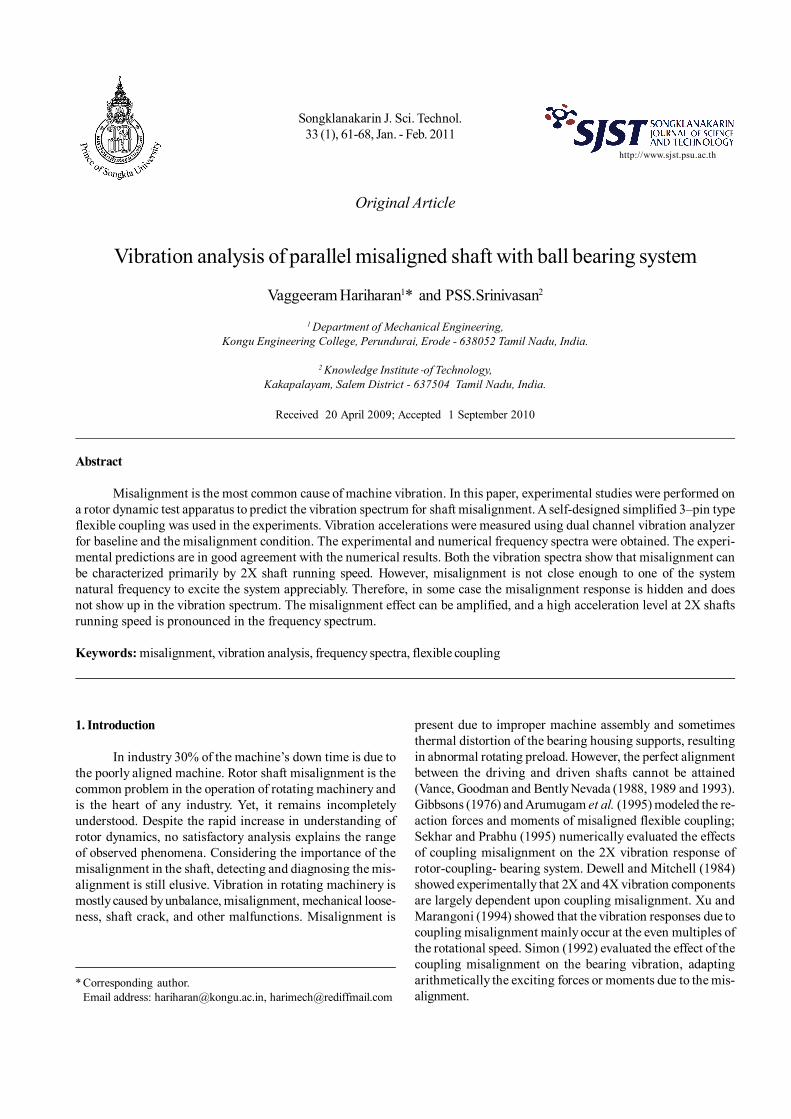
Couplings designed for experimental work are shownin Figure 1. Figure 1 (a) is showing the rigid coupling that hastwo flanges made of cast iron, connected by means of bolts.Shafts are rigidly connected by the coupling through keys.
Figure 1 (b) depicts the pin type flexible couplingassembly consisting of two flanges of different geometry. Thefirst coupling consists of a centre hole with the keyway toaccommodate the shaft rigidly with the flange. An equallyspaced three blind holes are drilled on the flange portion at apitch circle diameter to engage the pin of the other flange. Thesecond flange is also similar but instead of holes, three pinsare projected at the same pitch circle diameter to fit into thefirst flange blind hole. Then, rubber bushes are introducedin between to avoid the metal to metal contact.
The driver and driven shafts are connected to therespective flanges by means of parallel keys. Two flangesare connected through the pin covered with a rubber bush.Shafts, pins and keys are made of mild steel. The rubber bush
is used to give flexibility between the pin and the hole of theflange. It also takes care of the shaft misalignment. The dia-meter of the holes in flange is equal to the diameter of pinand the thickness of rubber bush. For this purpose, cast-ironmaterial is chosen for both flanges and the natural rubber isused for bush and pad. A rubber pad is used in between theflanges to obtain the flexibility of the coupling as shown inFigure 1(b). The dimensions of the pin type coupling andmaterials used are given in Tables 1 and 2, respectively.
3. Description of the Experimental Facility
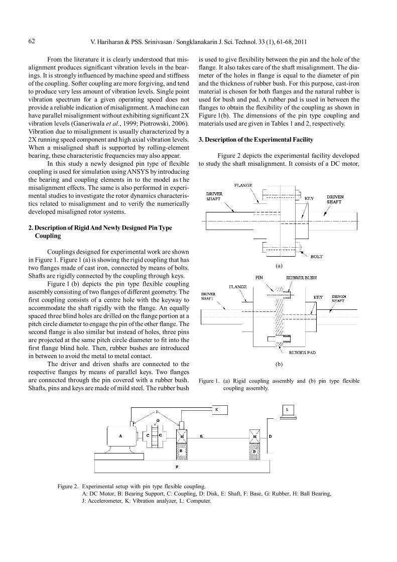
Figure 2 depicts the experimental facility developedto study the shaft misalignment. It consists of a DC motor,
Figure 2. Experimental setup with pin type flexible coupling.A: DC Motor, B: Bearing Support, C: Coupling, D: Disk, E: Shaft, F: Base, G: Rubber, H: Ball Bearing,J: Accelerometer, K: Vibration analyzer, L: Computer.
Figure 1. (a) Rigid coupling assembly and (b) pin type flexiblecoupling assembly.
(a)
(b)
63V. Hariharan & PSS. Srinivasan / Songklanakarin J. Sci. Technol. 33 (1), 61-68, 2011
a pin type flexible coupling or rigid coupling, and an overhung circular disc on the shaft. The shaft of 19 mm diameteris supported by two identical ball bearings. The bearing pe-destals are provided in such a way as to adjust in verticaldirection to create necessary linear misalignment. The shaftis driven by a 0.56 kW DC motor. A DC voltage controller isused to adjust the power supply of the motor and it can beoperated at different speeds.
3.1 Measurement and instrumentation
A piezoelectric accelerometer (Type AC102-A, Sl. No66760) is used along with the dual channel vibration analy-zer (Adash 4300-VA3/Czech Republic) of 8192 sampling fre-quency. For measuring 1600 spectral lines and four numberof averaging, frequency band of 0-1000 Hz is used.
The accelerometer is calibrated with the help of cali-bration test and fitted with the electrodynamic shaker andpower amplifier under known frequency and amplitude.The acceleration amplitude of the electrodynamic shaker iscompared with the acceleration amplitude of the accelero-meter to be calibrated. Then the vibration amplitudes of boththe electrodynamic shaker and test accelerometer are foundto be the same. The calibrated accelerometer is fitted over thebearing housing and connected with the vibration analyzer.Next, the measured data from the vibration analyzer arecollected at a computer terminal through a RS 232 interface.
4. Experimental Procedure
The experimental facility shown in Figure 2 is usedfor the misalignment test. Initially, the setup is run for a fewminutes to allow all minor vibrations to settle. Before creat-ing the misalignment, the shaft is checked for alignment. Todo this, the two dial gauge method is used to make perfectalignment.
First, two shafts are connected by rigid coupling andbolts. At this point, parallel misalignment of 0.2 mm is createdby adjusting the bearing pedestal in the vertical direction.Then the dial gauge is used to measure the shaft misalign-ment. The misaligned shaft system is run for a few minutesbefore measuring the vibration signals. These vibrationsignals are measured at four different speeds at both thedrive end and non-drive end. The same system is modeledand analyzed using ANSYS software. Table 4 indicates theexperiment and simulation results of vibration amplitude inm/s2 of both drive end (DE) and non-drive end (NDE) at dif-ferent speeds.
Next, the rigid coupling is replaced by the pin typeflexible coupling and the two dial gauge method is again usedto make perfect alignment of the pin type flexible couplingand shafts. Then the system is allowed to run in an alignedcondition for a few minutes. Measurements are taken againas said above. The shaft misalignment of 0.2 mm is createdby adjusting the bearing pedestal in the vertical direction.Following this, the amount of misalignment is measured
accurately using dial test indicator. Vibration signals aremeasured at four different speeds at both the drive end andthe non-drive end and recorded in the analyzer. Table 5relates to the experiment and simulation vibration amplitudein m/s2 of both DE and NDE at different speeds.
5. Numerical Method (Finite Element Modelling)
5.1 Modeling of the rotor shaft and coupling
Rotor shaft and couplings are modeled using Pro/Engineer wildfire-4 with the exact dimensions as used in theexperimental setup. The model is imported to ANSYS-11 soft-ware. Using ANSYS meshing, analysis is carried out. Thedimensions and the material properties used are listed inTable 1 and 2, respectively. Rigid coupling is also modeledand analyzed. Then, the same model is modified to the pintype flexible coupling and the material property of rubber isinitially defined as an isotropic material with Young’s modu-lus and Poisson’s ratio values. In this stage, the rubber acts
Table 1. Dimension of the pin type coupling assembly.
Sl. No Description Value
1 Shaft diameter 19 mm2 Hub diameter 40 mm3 Length of the hub 30 mm4 Outside diameter of flange
coupling and rubber pad 80 mm5 Number of holes for pin 36 Diameter of pin hole 11 mm7 Diameter of pin 6 mm8 Rubber bush
Outside diameter 11 mmInside diameter 6 mm
9 Keyway depthIn shaft 3.5 mmIn hub 2.8 mmKeyway cross sectionHeight 6 mmWidth 6 mm
10 Bolt diameter 6 mm
Table 2. Material properties.
Properties Cast-iron Mild steel Rubber
Young’s modulus (MPa) 1 x 10⁵ 2 x10⁵ 30Poisson ratio 0.23 0.3 0.49Density (kg/m3) 7250 7850 1140
V. Hariharan & PSS. Srinivasan / Songklanakarin J. Sci. Technol. 33 (1), 61-68, 201164
as a linear material. To convert it into non-linear material,hyper elastic property with Mooney Rivlin constants areintroduced. Maximum nine Mooney Rivlin constants areavailable (see ANSYS-11 help manual). In this analysis, allthe nine constants are used for better accuracy. The MooneyRivlin constants used in the present study are representedin Table 3. These constants account for non-linear propertyof the natural rubber. The surface to surface contact is con-sidered between the rubber and cast iron flanges
5.2 Meshing of domain
Before meshing or even building the model, it is im-portant to decide which one is more suitable - a free mesh ora mapped mesh for the analysis. A free mesh has no restric-tions in terms of element shapes, and has no specifiedpattern. A mapped mesh on the contrary, is restricted in termsof the element shape it contains and the pattern of the mesh.A mapped area mesh contains either quadrilateral or tri-angular elements, while the mapped volume mesh containshexahedron elements. In addition, a mapped mesh typicallyhas a regular pattern, with obvious rows of elements. In thistype of mesh, first it is necessary to build the geometry as aseries of fairly regular volumes and/or areas and the mappedmesh.
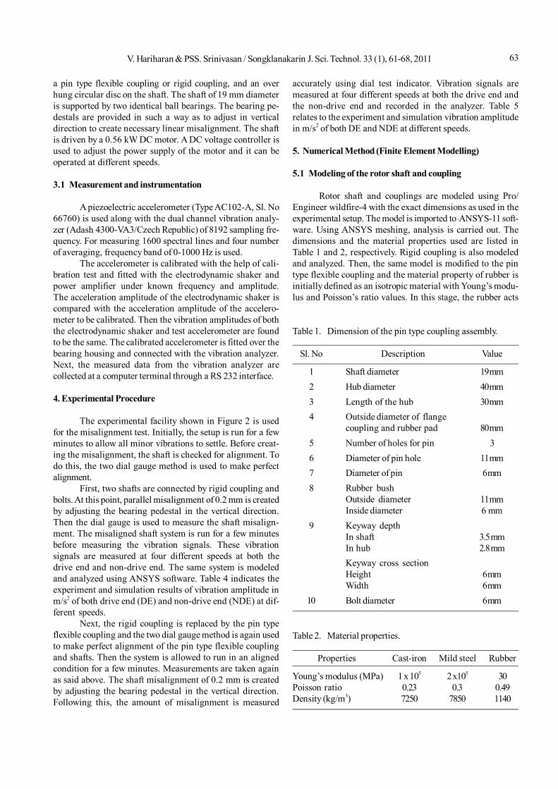
In the present model, mapped mesh has been usedwith the element type of SOLID 95. Smart element sizecontrol is used for mapped mesh. SOLID 95 is a higher orderversion of the 3D 8-noded solid element. It can tolerate irregu-lar shapes without the loss of accuracy. In fact, SOLID 95elements have compatible displacement shapes and are wellsuited to model curved boundaries. The meshed model ispresented in Figure 3.
5.3 Applying the boundary conditions and loads
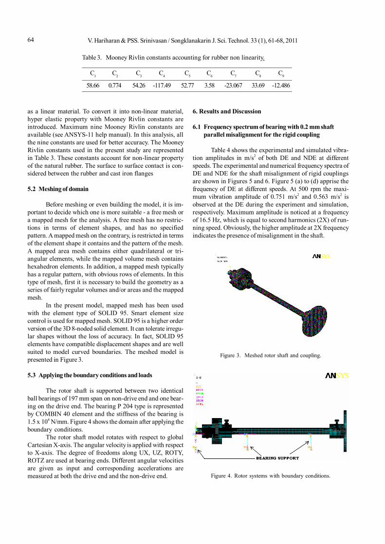
The rotor shaft is supported between two identicalball bearings of 197 mm span on non-drive end and one bear-ing on the drive end. The bearing P 204 type is representedby COMBIN 40 element and the stiffness of the bearing is1.5 x 104 N/mm. Figure 4 shows the domain after applying theboundary conditions.
The rotor shaft model rotates with respect to globalCartesian X-axis. The angular velocity is applied with respectto X-axis. The degree of freedoms along UX, UZ, ROTY,ROTZ are used at bearing ends. Different angular velocitiesare given as input and corresponding accelerations aremeasured at both the drive end and the non-drive end.
6. Results and Discussion
6.1 Frequency spectrum of bearing with 0.2 mm shaftparallel misalignment for the rigid coupling
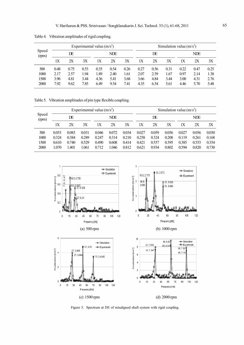
Table 4 shows the experimental and simulated vibra-tion amplitudes in m/s2 of both DE and NDE at differentspeeds. The experimental and numerical frequency spectra ofDE and NDE for the shaft misalignment of rigid couplingsare shown in Figures 5 and 6. Figure 5 (a) to (d) apprise thefrequency of DE at different speeds. At 500 rpm the maxi-mum vibration amplitude of 0.751 m/s2 and 0.563 m/s2 isobserved at the DE during the experiment and simulation,respectively. Maximum amplitude is noticed at a frequencyof 16.5 Hz, which is equal to second harmonics (2X) of run-ning speed. Obviously, the higher amplitude at 2X frequencyindicates the presence of misalignment in the shaft.
Figure 3. Meshed rotor shaft and coupling.
Figure 4. Rotor systems with boundary conditions.
Table 3. Mooney Rivlin constants accounting for rubber non linearity.
C1 C2 C3 C4 C5 C6 C7 C8 C9
58.66 0.774 54.26 -117.49 52.77 3.58 -23.067 33.69 -12.486
65V. Hariharan & PSS. Srinivasan / Songklanakarin J. Sci. Technol. 33 (1), 61-68, 2011
Table 5. Vibration amplitudes of pin type flexible coupling.
Experimental value (m/s2) Simulation value (m/s2)
DE NDE DE NDE
1X 2X 3X 1X 2X 3X 1X 2X 3X 1X 2X 3X
500 0.053 0.083 0.031 0.046 0.072 0.034 0.027 0.059 0.056 0.027 0.056 0.0301000 0.324 0.384 0.289 0.247 0.314 0.210 0.258 0.324 0.208 0.119 0.261 0.1681500 0.610 0.740 0.529 0.490 0.608 0.414 0.421 0.557 0.395 0.385 0.553 0.3542000 1.070 1.401 1.061 0.712 1.046 0.812 0.621 0.934 0.802 0.594 0.820 0.730
Speed(rpm)
Table 4. Vibration amplitudes of rigid coupling.
Experimental value (m/s2) Simulation value (m/s2)
DE NDE DE NDE
1X 2X 3X 1X 2X 3X 1X 2X 3X 1X 2X 3X
500 0.48 0.75 0.53 0.35 0.54 0.26 0.27 0.56 0.31 0.22 0.47 0.251000 2.17 2.57 1.94 1.89 2.40 1.61 2.07 2.59 1.67 0.97 2.14 1.381500 3.96 4.81 3.44 4.36 5.41 3.68 3.66 4.84 3.44 3.00 4.31 2.762000 7.92 9.62 7.85 6.49 9.54 7.41 4.35 6.54 5.61 4.46 5.70 5.48
Speed(rpm)
Figure 5. Spectrum at DE of misaligned shaft system with rigid coupling.
(a) 500 rpm (b) 1000 rpm
(c) 1500 rpm (d) 2000 rpm
V. Hariharan & PSS. Srinivasan / Songklanakarin J. Sci. Technol. 33 (1), 61-68, 201166
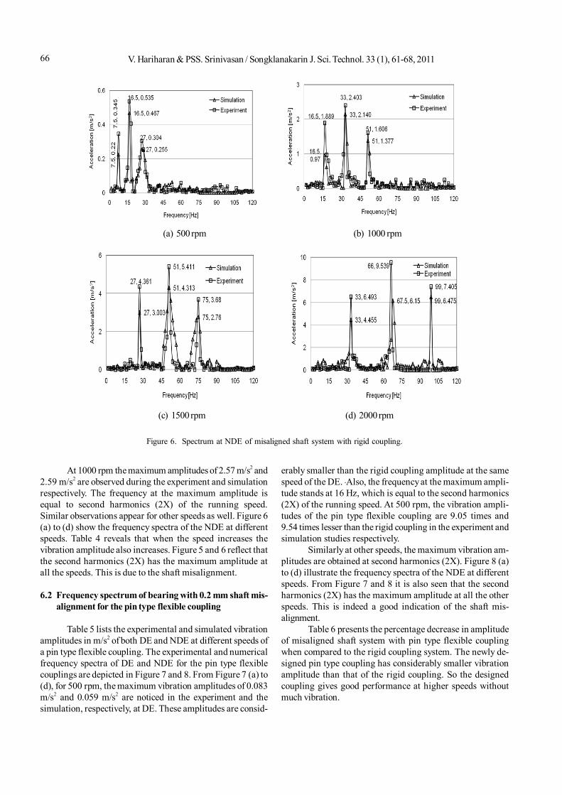
At 1000 rpm the maximum amplitudes of 2.57 m/s2 and2.59 m/s2 are observed during the experiment and simulationrespectively. The frequency at the maximum amplitude isequal to second harmonics (2X) of the running speed.Similar observations appear for other speeds as well. Figure 6(a) to (d) show the frequency spectra of the NDE at differentspeeds. Table 4 reveals that when the speed increases thevibration amplitude also increases. Figure 5 and 6 reflect thatthe second harmonics (2X) has the maximum amplitude atall the speeds. This is due to the shaft misalignment.
6.2 Frequency spectrum of bearing with 0.2 mm shaft mis-alignment for the pin type flexible coupling
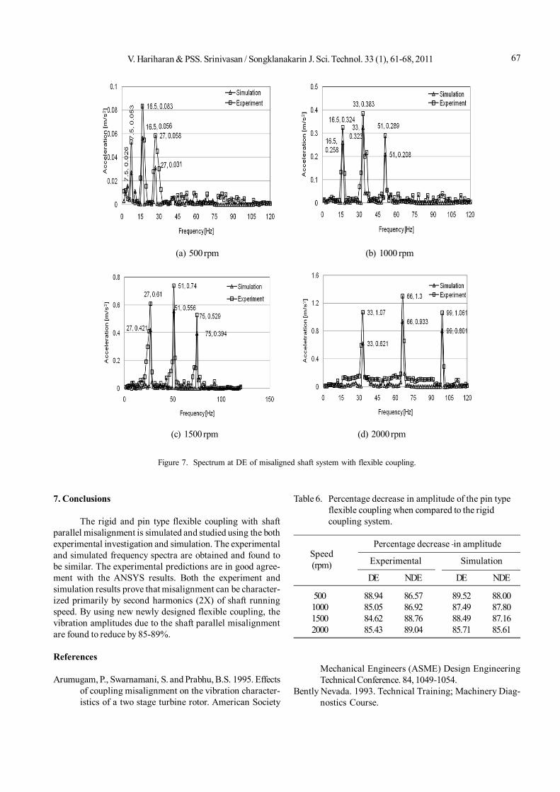
Table 5 lists the experimental and simulated vibrationamplitudes in m/s2 of both DE and NDE at different speeds ofa pin type flexible coupling. The experimental and numericalfrequency spectra of DE and NDE for the pin type flexiblecouplings are depicted in Figure 7 and 8. From Figure 7 (a) to(d), for 500 rpm, the maximum vibration amplitudes of 0.083m/s2 and 0.059 m/s2 are noticed in the experiment and thesimulation, respectively, at DE. These amplitudes are consid-
erably smaller than the rigid coupling amplitude at the samespeed of the DE. Also, the frequency at the maximum ampli-tude stands at 16 Hz, which is equal to the second harmonics(2X) of the running speed. At 500 rpm, the vibration ampli-tudes of the pin type flexible coupling are 9.05 times and9.54 times lesser than the rigid coupling in the experiment andsimulation studies respectively.
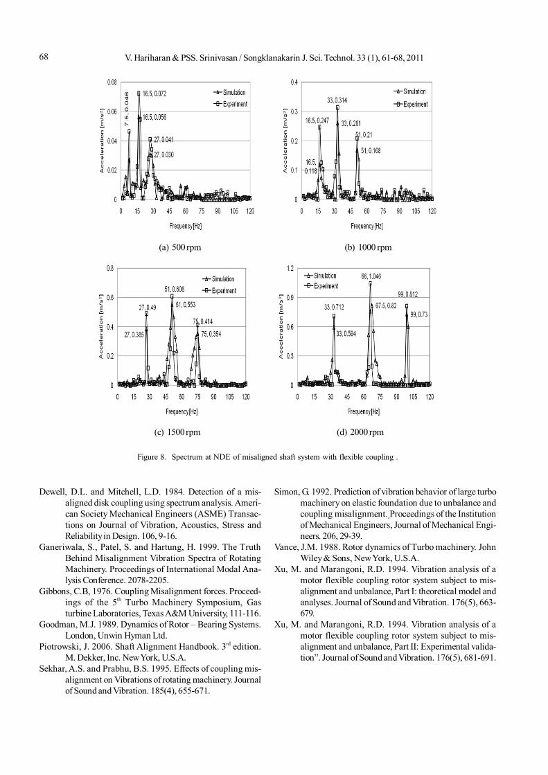
Similarly at other speeds, the maximum vibration am-plitudes are obtained at second harmonics (2X). Figure 8 (a)to (d) illustrate the frequency spectra of the NDE at differentspeeds. From Figure 7 and 8 it is also seen that the secondharmonics (2X) has the maximum amplitude at all the otherspeeds. This is indeed a good indication of the shaft mis-alignment.
Table 6 presents the percentage decrease in amplitudeof misaligned shaft system with pin type flexible couplingwhen compared to the rigid coupling system. The newly de-signed pin type coupling has considerably smaller vibrationamplitude than that of the rigid coupling. So the designedcoupling gives good performance at higher speeds withoutmuch vibration.
(a) 500 rpm (b) 1000 rpm
(c) 1500 rpm (d) 2000 rpm
Figure 6. Spectrum at NDE of misaligned shaft system with rigid coupling.
67V. Hariharan & PSS. Srinivasan / Songklanakarin J. Sci. Technol. 33 (1), 61-68, 2011
(a) 500 rpm (b) 1000 rpm
(c) 1500 rpm (d) 2000 rpm
Figure 7. Spectrum at DE of misaligned shaft system with flexible coupling.
Table 6. Percentage decrease in amplitude of the pin typeflexible coupling when compared to the rigidcoupling system.
Percentage decrease in amplitude
Experimental Simulation
DE NDE DE NDE
500 88.94 86.57 89.52 88.001000 85.05 86.92 87.49 87.801500 84.62 88.76 88.49 87.162000 85.43 89.04 85.71 85.61
Speed(rpm)
7. Conclusions
The rigid and pin type flexible coupling with shaftparallel misalignment is simulated and studied using the bothexperimental investigation and simulation. The experimentaland simulated frequency spectra are obtained and found tobe similar. The experimental predictions are in good agree-ment with the ANSYS results. Both the experiment andsimulation results prove that misalignment can be character-ized primarily by second harmonics (2X) of shaft runningspeed. By using new newly designed flexible coupling, thevibration amplitudes due to the shaft parallel misalignmentare found to reduce by 85-89%.
References
Arumugam, P., Swarnamani, S. and Prabhu, B.S. 1995. Effectsof coupling misalignment on the vibration character-istics of a two stage turbine rotor. American Society
Mechanical Engineers (ASME) Design EngineeringTechnical Conference. 84, 1049-1054.
Bently Nevada. 1993. Technical Training; Machinery Diag-nostics Course.
V. Hariharan & PSS. Srinivasan / Songklanakarin J. Sci. Technol. 33 (1), 61-68, 201168
Dewell, D.L. and Mitchell, L.D. 1984. Detection of a mis-aligned disk coupling using spectrum analysis. Ameri-can Society Mechanical Engineers (ASME) Transac-tions on Journal of Vibration, Acoustics, Stress andReliability in Design. 106, 9-16.
Ganeriwala, S., Patel, S. and Hartung, H. 1999. The TruthBehind Misalignment Vibration Spectra of RotatingMachinery. Proceedings of International Modal Ana-lysis Conference. 2078-2205.
Gibbons, C.B, 1976. Coupling Misalignment forces. Proceed-ings of the 5th Turbo Machinery Symposium, Gasturbine Laboratories, Texas A&M University, 111-116.
Goodman, M.J. 1989. Dynamics of Rotor – Bearing Systems.London, Unwin Hyman Ltd.
Piotrowski, J. 2006. Shaft Alignment Handbook. 3rd edition.M. Dekker, Inc. New York, U.S.A.
Sekhar, A.S. and Prabhu, B.S. 1995. Effects of coupling mis-alignment on Vibrations of rotating machinery. Journalof Sound and Vibration. 185(4), 655-671.
Figure 8. Spectrum at NDE of misaligned shaft system with flexible coupling .
(a) 500 rpm (b) 1000 rpm
(c) 1500 rpm (d) 2000 rpm
Simon, G. 1992. Prediction of vibration behavior of large turbomachinery on elastic foundation due to unbalance andcoupling misalignment. Proceedings of the Institutionof Mechanical Engineers, Journal of Mechanical Engi-neers. 206, 29-39.
Vance, J.M. 1988. Rotor dynamics of Turbo machinery. JohnWiley & Sons, New York, U.S.A.
Xu, M. and Marangoni, R.D. 1994. Vibration analysis of amotor flexible coupling rotor system subject to mis-alignment and unbalance, Part I: theoretical model andanalyses. Journal of Sound and Vibration. 176(5), 663-679.
Xu, M. and Marangoni, R.D. 1994. Vibration analysis of amotor flexible coupling rotor system subject to mis-alignment and unbalance, Part II: Experimental valida-tion”. Journal of Sound and Vibration. 176(5), 681-691.