Embed Size (px)
Citation preview
Chapter 8
Vibration Analysis of Cracked Beams Using the FiniteElement Method
A. S. Bouboulas, S. K. Georgantzinos andN. K. Anifantis
Additional information is available at the end of the chapter
http://dx.doi.org/10.5772/51173
1. Introduction
Most of the members of engineering structures operate under loading conditions, whichmay cause damages or cracks in overstressed zones. The presence of cracks in a structuralmember, such as a beam, causes local variations in stiffness, the magnitude of which mainlydepends on the location and depth of the cracks. These variations, in turn, have a significanteffect on the vibrational behavior of the entire structure. To ensure the safe operation ofstructures, it is extremely important to know whether their members are free of cracks, andshould any be present, to assess their extent. The procedures often used for detection are di‐rect procedures such as ultrasound, X-rays, etc. However, these methods have proven to beinoperative and unsuitable in certain cases, since they require expensive and minutely de‐tailed inspections [1]. To avoid these disadvantages, in recent decades, researchers have fo‐cused on more efficient procedures in crack detection using vibration-based methods [2].Modelling of a crack is an important aspect of these methods.
The majority of published studies assume that the crack in a structural member always re‐mains open during vibration [3-7]. However, this assumption may not be valid when dy‐namic loadings are dominant. In this case, the crack breathes (opens and closes) regularlyduring vibration, inducing variations in the structural stiffness. These variations cause thestructure to exhibit non-linear dynamic behavior [8]. The main distinctive feature of this be‐havior is the presence of higher harmonic components. In particular, a beam with a breath‐ing crack shows natural frequencies between those of a non-cracked beam and those of afaulty beam with an open crack. Therefore, in these cases, vibration-based methods shouldemploy breathing crack models to provide accurate conclusions regarding the state of dam‐age. Several researchers [9-11] have developed breathing crack models considering only the
© 2012 Bouboulas et al.; licensee InTech. This is an open access article distributed under the terms of theCreative Commons Attribution License (http://creativecommons.org/licenses/by/3.0), which permitsunrestricted use, distribution, and reproduction in any medium, provided the original work is properly cited.
fully open and fully closed crack states. However, experiments have indicated that the tran‐sition between these two crack states does not occur instantaneously [12]. In reference [13]represented the interaction forces between two segments of a beam, separated by a crack,using time-varying connection matrices. These matrices were expanded in Fourier series tosimulate the alternation of a crack opening and closing. However, the implementation ofthis study requires excessive computer time. In references [14, 15] considered a simple peri‐odic function to model the time-varying stiffness of a beam. However, this model is limitedto the fundamental mode, and thus, the equation of motion for the beam must be solved.
A realistic model of a breathing crack is difficult to create due to the lack of fundamentalunderstanding about certain aspects of the breathing mechanism. This involves not only theidentification of variables affecting the breathing crack behavior, but also issues for evaluat‐ing the structural dynamic response of the fractured material. It is also not yet entirely clearhow partial closure interacts with key variables of the problem. The actual physical situationrequires a model that accounts for the breathing mechanism and for the interaction betweenexternal loading and dynamic crack behavior. When crack contact occurs, the unknowns arethe field singular behavior, the contact region and the distribution of contact tractions on theclosed region of the crack. The latter class of unknowns does not exist in the case withoutcrack closure. This type of complicated deformation of crack surfaces constitutes a non-line‐ar problem that is too difficult to be treated with classical analytical procedures. Thus, a suit‐able numerical implementation is required when partial crack closure occurs.
In reference [16] constructed a lumped cracked beam model from the three-dimensional for‐mulation of the general problem of elasticity with unilateral contact conditions on the cracklips. The problem of a beam with an edge crack subjected to a harmonic load was consid‐ered in [17]. The breathing crack behavior was simulated as a frictionless contact problembetween the crack surfaces. Displacement constraints were applied to prevent penetration ofthe nodes of one crack surface into the other crack surface. In reference [18] studied theproblem of a cantilever beam with an edge crack subjected to a harmonic load. The breath‐ing crack behavior was represented via a frictionless contact model of the interacting surfa‐ces. In [19] studied the effect of a helicoidal crack on the dynamic behavior of a rotatingshaft. This study used a very accurate and simplified model that assumes linear stress andstrain distributions to calculate the breathing mechanism. The determination of open andclosed parts of the crack was performed through a non-linear iterative procedure.
This chapter presents the vibrational behavior of a beam with a non-propagating edge crack.To treat this problem, a two-dimensional beam finite element model is employed. The breath‐ing crack is simulated as a full frictional contact problem between the crack surfaces, while theregion around the crack is discretized into a number of conventional finite elements. This non-linear dynamic problem is solved using an incremental iterative procedure. This study is ap‐plied for the case of an impulsive loaded cantilever beam. Based on the derived time response,conclusions are extracted for the crack state (i.e. open or closed) over the time. Furthermore, thetime response is analyzed by Fourier and continuous wavelet transforms to show the sensitivi‐ty of the vibrational behavior for both a transverse and slant crack of various depths and posi‐tions. Comparisons are performed with the corresponding vibrational behavior of the beam
Advances in Vibration Engineering and Structural Dynamics182
when the crack is considered as always open. To assess further the validity of this technique,the quasi-static problem of a three-dimensional rotating beam with a breathing crack is alsopresented. The formulation of this latter problem is similar to the former one. The main differ‐ences are: the inertia and damping terms are ignored, any possible sliding occurs in two di‐mensions and the iterative procedure is applied to load instead of time increment. Theflexibility of the rotating beam and the crack state over time are presented for both a transverseand slant crack of various depths. The validation of the present study is demonstrated throughcomparisons with results available from the literature.
2. Finite element formulation
In the following, both a two and three-dimensional beam models with a non-propagatingsurface crack are presented. For both models the crack surfaces are assumed to be planarand smooth and the crack thickness negligible. The beam material properties are consideredlinear elastic and the displacements and strains are assumed to be small. The region aroundthe crack is discretized into conventional finite elements. The breathing crack behavior is si‐mulated as a full frictional contact problem between the crack surfaces, which is an inherent‐ly non-linear problem. Any possible sliding is assumed to obey Coulomb’s law of friction,and penetration between contacting areas is not allowed. The non-linear dynamic problemis discussed for the two-dimensional model and the corresponding quasi-static for the three-dimensional model. Both problems are solved utilizing incremental iterative procedures. Forcompleteness reasons, the contact analysis in three dimensions and the formulation and sol‐ution of the non-linear dynamic problem are presented below.
a. Two-dimensional model
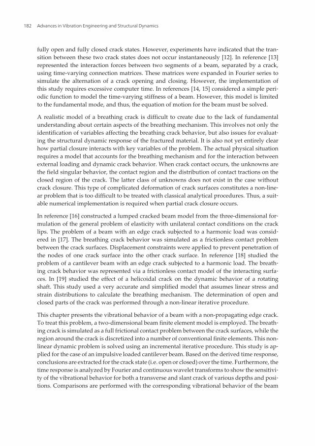
Figure 1 illustrates a two-dimensional straight cantilever beam with a rectangular cross-sec‐tion b ×h and length L . A breathing crack of depth a exists at position L c . The crack is locatedat the upper edge of the beam and forms an angle θ with respect to the x − axis of the global co‐ordinate system x, y . An impulsive load is applied transversally at point A (Figure 1).
Figure 1. Cracked two-dimensional beam model.
Vibration Analysis of Cracked Beams Using the Finite Element Methodhttp://dx.doi.org/10.5772/51173
183
In the finite element method (FEM) framework, the equilibrium equation governing the dy‐namic behavior of the model is:
MU + CU + KU =R (1)
where M , C , and K are the mass, damping, and stiffness matrices, respectively. The time-de‐pendent vectors U , U , U , and R denote the nodal accelerations, velocities, displacements,and external forces, respectively, in terms of a global Cartesian coordinate system x, y .
b. Three-dimensional model
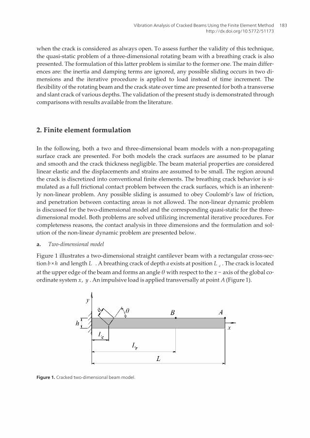
Figure 2 depicts a three-dimensional cantilever beam with length 2L and circular cross-sec‐tion of radius R . A breathing crack of depth a exists at the middle of the beam. The crackhas either straight or curved front (Figures 2b and 2c). The slant crack forms angles θy , θz
with respect to (x, y) and (x, z) planes, respectively. Two different load cases are separatelyapplied at the tip of the cantilever beam, i.e., twisting moment T and bending moment M ,respectively. The bending moment is applied in several aperture angles M =M (φ) , in orderto simulate a rotating load on a fixed beam. The components My =My(φ) and Mz =Mz(φ) ofthe bending moment M (φ) , along the directions of axes y and z , respectively, are functionsof the aperture angle.
Figure 2. Cracked three-dimensional beam; (a) cracked beam subjected to bending and twisting moments; (b)straight-front crack, and (c) curved front crack.
Advances in Vibration Engineering and Structural Dynamics184
The equilibrium equation governing the quasi-static behavior of the model is:
KU =R (2a)
where K is the stiffness matrix, U denotes the nodal displacements and R represent the ex‐ternal forces, respectively, in terms of a global Cartesian coordinate system x, y, z .
The equilibrium equation governing the quasi-static behavior of the model is:
KU =R (2b)
where K is the stiffness matrix, U denotes the nodal displacements and R represent the ex‐ternal forces, respectively, in terms of a global Cartesian coordinate system x, y, z .
c. Crack modelling
Considering the three-dimensional model, the crack is composed of two surfaces, which in‐tersect on the crack front. Parts of these two surfaces may come into contact on an interface.The size of the interface can vary during the interaction between the load and the structure,but the interface is usually comprised of two parts, i.e., an adhesive part and a slipping part,depending on the friction conditions maintained between the contacting surfaces. In theopen crack state, the corresponding part of the crack surface is subjected to traction-free con‐ditions. The so-called slave–master concept that is widely used for the implementation ofcontact analysis is adopted in this work for prediction of the crack-surface interference. Oneof the two crack surfaces is considered as the master surface, with the other as the slave.Both master and slave crack surfaces are defined by the local coordinate systems( xJ
1, xJ
2, xJ
3) , with J= I for master surface and J= II for slave surface. The axes xJ
3 define the
direction of the unit outward normal vector of the corresponding surfaces. The nodes thatbelong to the master and slave surfaces are called the master and slave nodes, respectively.Contact segments that span master nodes cover the contact surface of the structure. There‐fore, the above problem can be regarded as contact between a slave node and a point on amaster segment. This point may be located at a node, an edge, or a point of a master seg‐ment. A slave node makes contact with only one point on the master segment, but one mas‐ter segment can make contact with one or more slave nodes at each time. For each contactpair, the mechanical contact conditions are expressed in a local coordinate system in the di‐rection of the average normal to the boundaries of the bodies. Symbols ui and Ri , i =1, 2, 3denote nodal displacement and force components, respectively, defined on the local coordi‐nate systems ( xJ
1, xJ
2, xJ
3) , j = I, II . The subscripts that indicate nodal numbers are dropped
for simplicity from this point forward.
Recalling the equilibrium condition, the force between the components is always expressedby the following equations:
RIi+ RII
i=0, i =1, 2, 3 (3)
Vibration Analysis of Cracked Beams Using the Finite Element Methodhttp://dx.doi.org/10.5772/51173
185
In the open crack state, the following traction-free conditions are held between the com‐ponents:
RIi= RII
i=0, i =1, 2, 3 (4)
From the definition of adhesion, the displacement components on the corresponding cracksurfaces are interconnected by the equations:
uIi+ uII
i=0, i =1, 2 (5)
When an initial gap g 0 exists in the normal direction between the master and slave nodes ofthe corresponding node pair, the displacement component along the normal direction is:
uI3
+ uII3= g 0 (6)
The slip state does not prohibit the existence of a gap between the crack surfaces, so equa‐tion (5) is still valid in this case. However, the tangential force component is defined interms of friction as:
RIi± μ RI
3=0, i =1, 2 (7)
where μ is the coefficient of Coulomb friction. Concerning the corresponding two-dimen‐sional contact analysis, the aforementioned approach is straightforwardly used neglectingone of the three directions.
d. Incremental iterative procedure
The simulation of the breathing crack behavior as a full frictional contact problem consti‐tutes the present study as a non-linear dynamic problem. In the FEM framework, a non-line‐ar dynamic problem described by an equation such equation (1) is solved using an implicitdirect integration scheme [20]. According to this method, the solution time interval of inter‐est 0, T is subdivided into N equal time increments Δt , where Δt =T / N . The variation ofaccelerations, velocities, and displacements within the time increment has a certain formand depends on the type of time integration scheme. Approximate solutions of equation (1)are sought at times 0, Δt , 2Δt , …, t , t + Δt , …, T . The calculations performed to obtain thesolution at time t + Δt require that the solutions at previous times 0, Δt , 2Δt , …, t areknown. The initial conditions of accelerations, velocities, and displacements at time zero arealso required. Thus, equation (1) is evaluated at time t + Δt as:
M Ut+Δt + C Ut+Δt + K Ut+Δt = Rt+Δt (8)
where the left-hand subscripts denote the time.
Advances in Vibration Engineering and Structural Dynamics186
The solution to this non-linear problem requires an iterative procedure. Employing themodified Newton-Raphson iteration method [20], the displacement vector Ut+Δt (k ) at timet + Δt and iteration k is given by:
Ut+Δt (k ) = Ut+Δt (k−1) + ΔU (k ) (9)
while equations (8) are written as:
M Ut+Δt (k ) + C Ut+Δt (k ) + KtT
ΔU (k ) = Rt+Δt − Ft+Δt (k−1) (10)
where the right-hand subscripts in brackets represent the iteration number, withk =1, 2, 3, … . The symbols Kt
T , Ft+Δt (k−1) and ΔU (k ) denote the tangent stiffness matrix,
the nodal force vector, which is equivalent to the element stresses, and the incremental no‐dal displacement vector, respectively. The iterative method is called the modified Newton–Raphson method, since the tangent stiffness matrix is not calculated in every iteration,which is the case for the full method [20].
Employing for example an implicit time integration scheme, formulas are implementedthat relate the nodal accelerations, velocities, and displacement vectors at time t + Δt tothose at previous times. Considering these formulas, equation (10) can be written in thefollowing form [20]:
K⌢t
TΔU (k ) =ΔR
⌢(k−1)(11)
where the matrix K⌢t
T is a function of the tangent stiffness matrix, mass matrix, and damping
matrix, while the vector ΔR⌢(k−1)
contains the nodal force vector and contributions from the in‐
ertia and damping of the system. In the first iteration, the vectors ΔR⌢(0)
and Ut+Δt (0) are equal tothe corresponding vectors of the last iteration at the previous time. In each iteration, the latest
estimates of displacements are used to evaluate the vector ΔR⌢(k−1)
. Then, the incremental dis‐placements ΔU (k ) are obtained by solving equations (11), while the nodal displacements
Ut+Δt (k ) are derived from equations (9). The iteration proceeds until the nodal displacementsvector of the last iteration Ut+Δt (k ) are approximately equal to the corresponding vector of theprevious iteration Ut+Δt (k−1) . This convergence criterion is expressed as
| Ut+Δt (k )− Ut+Δt (k−1)
Ut+Δt (k )| ≤ε (12)
Vibration Analysis of Cracked Beams Using the Finite Element Methodhttp://dx.doi.org/10.5772/51173
187
where ε is a small numerical quantity.
Considering that the problem has been solved for time t , and consequently, vectors Ut and Rt
are known for the entire structure. To determine the corresponding displacement and forcesvectors at time t + Δt , the equations (3)-(7) are written in incremental form as following:
( ΔI Ri)t+Δt + ( ΔII Ri)
t+Δt =0, i =1, 2 (13)
( ΔI Ri)t+Δt = − ( RII
i)t , i =1, 2 (14)
( uI1)t + ( ΔI u1)
t+Δt = ( uII1)t + ( ΔII u1)
t+Δt (15)
( uI2)t + ( ΔI u2)
t+Δt = ( uII2)t + ( ΔII u2)
t+Δt − g 0 (16)
( RI1)t + ( ΔI R1)
t+Δt = ± μ( ( RI2)t + ( ΔI R2)
t+Δt ) (17)
AssumptionDecision
Open Contact
Open ΔII u3m− ΔI u3m uI3m−1− uII
3m−1 + g 0 ΔII u3m− ΔI u3m≤ uI3m−1− uII
3m−1 + g 0
Contact fI3m−1 + ΔI f 3m≥0 fI
3m−1 + ΔI f 3m0
Adhesion Slip
Adhesion | fIim−1 + ΔI f im | |μ( fI
3m−1 + ΔI f 3m) | , i = 1, 2 | fIim−1 + ΔI f im | ≥ |μ( fI
3m−1 + ΔI f 3m) | , i = 1, 2
Slip ( fIim−1 + ΔI f im)( ΔI f im− ΔII f im)0, i = 1, 2 ( fI
im−1 + ΔI f im)( ΔI f im− ΔII f im)≤0, i = 1, 2
Table 1. Definition of contact status.
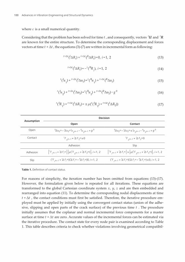
For reasons of simplicity, the iteration number has been omitted from equations (13)-(17).However, the formulation given below is repeated for all iterations. These equations aretransformed to the global Cartesian coordinate system x, y, z and are then embedded andrearranged into equation (11). To determine the corresponding nodal displacements at timet + Δt , the contact conditions must first be satisfied. Therefore, the iterative procedure em‐ployed must be applied by initially using the convergent contact status (union of the adhe‐sive, slipping and open parts of the crack surface) of the previous time t . The procedureinitially assumes that the coplanar and normal incremental force components for a mastersurface at time t + Δt are zero. Accurate values of the incremental forces can be estimated viathe iterative procedure. The contact state for every node pair is examined according to Table1. This table describes criteria to check whether violations involving geometrical compatibil‐
Advances in Vibration Engineering and Structural Dynamics188
ity and force continuity have occurred. Where necessary, appropriate changes from open tocontact or from adhesion to slip states and vice versa are made to identify the equilibriumstate of the contact conditions. The new contact condition is applied to the node pair closestto the change. If the change is from the open to the contact state, then the adhesion conditionis adjusted. When the iterative procedure converges, the incremental nodal values Δt+Δt Uand Δt+Δt R are known for the entire structure. After calculating the total nodal values, theprocedure goes to the next step of the time increment and continues until the final time in‐crement is reached. The problem solution is then attained.
3. Local flexibilities in cracked beams
A crack introduces local flexibilities in the stiffness of the structure due to strain energy con‐centration. Although local flexibilities representing the fracture in stationary structures areconstant for open cracks, the breathing mechanism causes their time dependence. In a fixeddirection, local flexibilities of rotating beams change also with time due to the breathingmechanism. Evidently, the vibrational response of a rotating cracked beam depends on thecrack opening and closing pattern in one cycle.
Since the torsional and bending vibrations are dominant in rotating beams, in this chapter it isassumed that the corresponding local flexibilities are also dominant in the local flexibility ma‐trix, neglecting the cross-coupling terms. Numerical results showed that the off-diagonal coef‐ficients of this matrix are at least two orders of magnitude lower than the diagonal ones, andthus are considered negligible. Therefore, the presence of the crack can equivalently represent‐ed by a diagonal local flexibility matrix, independent of the crack contact conditions.
The exact relationship between the fracture characteristics and the induced local flexibilitiesis difficult to be determined by the strain energy approach, because, stress intensity factorexpressions for this complex geometry are not available. For the computation of the localcrack compliance, a finite element method was used. According to the point load displace‐ment method, if at some node preferable lying on the tip of the beam is applied the externalload vector {Q}= {T My Mz}Τ , then at the same node the resulting rotations{Θ}={Θx Θy Θz}Τ are:
cx 0 00 cy 00 0 cz
{ TMy
Mz
}= {Θx
Θy
Θz
} (18)
In equation (18), cr , r = x, y, z are the diagonal coefficients of the local flexibility matrix. Un‐der the application of a particular load component Qr at the r - direction, the above equationis then simplified as follows:
Vibration Analysis of Cracked Beams Using the Finite Element Methodhttp://dx.doi.org/10.5772/51173
189
Θr =crQr (19)
where Θr , r = x, y, z is the induced rotation, and cr is the local flexibility component thatcorresponds to the particular loading mode Qr . Equation (19) can be used for the computa‐tion of the local flexibility coefficients, as described in the following. When the original non-cracked beam is uploaded until the load Qro , a rotation is imposed in r - direction, such thatequation (19) gives:
qro =croQro (20)
where cro is the flexibility of the original structure. The deformation of the cracked beamwhen loaded at the same node gives:
Θrc = crcQrc (21)
where crc is the flexibility of the cracked beam, and Qrc , Θrc the applied load and the result‐ing rotation, respectively. Between the flexibilities of the original and the fractured structureholds the condition
crc = cr + cro (22)
where cr is the local flexibility due to the crack itself. Assuming that the applied load levelsare of the same magnitude, i.e. Qrc =Qro =Qr , after some manipulation, equations (19)-(23)yield the local flexibility coefficient in the r - direction
cr =Θrc −Θro
Qr(23)
Equation (23) is used to compute the coefficients of the local flexibility matrix c utilizingthe FEM results. Tip loads Qr , r = x, y, z are applied independently, and the resulting rota‐tions Θr are evaluated. The rotations of the original structure Qro , are evaluated for FEMmodels that do not present crack but have similar meshing with the cracked models. Whenfractured models are examined, FEM results are computed for several values of crack depthand different loading conditions.
4. Response analysis
The response derived from equations (9) and (11) cannot be examined directly to distinguishthe breathing crack effects. For this reason, fast Fourier and continuous wavelet transforms
Advances in Vibration Engineering and Structural Dynamics190
are employed. These two popular transforms in signal analysis are briefly discussed belowfor reasons of completeness, and more information can be found in references [21, 22].
The fast Fourier transform (FFT) is a perfect tool for finding the frequency components ina signal of stationary nature. Unfortunately, FFT cannot show the time point at which aparticular frequency component occurs. Therefore, FFT is not a suitable tool for a non-sta‐tionary signal, such as the impulsive response of the cracked cantilever beam consideredin this study, which requires time-frequency representation. To overcome this FFT defi‐ciency, the short time Fourier transform (STFT) could be adopted, which maps a signal in‐to a two-dimensional function of time and frequency. This windowing technique analyzesonly a small section of the signal at a time. However, the information about time and fre‐quency that is obtained has a limited precision that is determined by the size of the win‐dow, which is the same for all frequencies.
Wavelet transforms are a novel and precise way to analyze signals and can overcome theproblems that other signal transforms exhibit. The most important advantage of wavelettransformations is that they have changeable window dimensions. For low frequencies, thewindow is wide, while for high frequencies, it is narrow. Thus, maximum time frequencyresolution is provided for all frequency intervals.
The continuous wavelet transform (CWT), as employed in this study, is defined mathe‐matically as:
W f s ,u =1s ∫−∞∞
f (t)ψ ∗(t −u
s )dt (24)
where f (t) is the signal for analysis, ψ ∗(t) is the complex conjugate of the mother waveletψ(t) and s and u are real-valued parameters used to characterize the dilation and translationfeatures of the wavelet.
The CWT has an inverse that permits recovery of the signal from its coefficient W f s ,u and isdefined as:
f (t)=1
Cψ∫−∞
∞
∫−∞
∞
W f s ,uψ(t −u
s )1s 2 dsdu (25)
5. Results and discussions
a. Accuracy study
i. Two-dimensional model
To demonstrate the accuracy of the presented study, a two-dimensional beam is consideredwith length L =1.5m , cross-section a / R =1.0 , modulus of elasticity E =2.06×10¹¹Pa , mass
Vibration Analysis of Cracked Beams Using the Finite Element Methodhttp://dx.doi.org/10.5772/51173
191
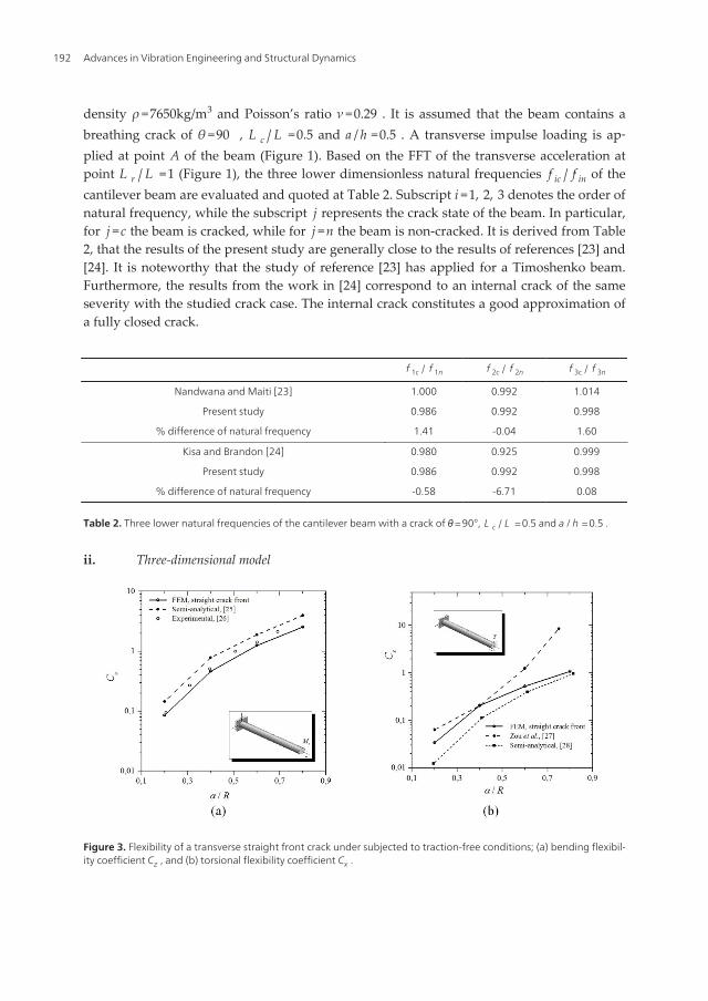
density ρ =7650kg/m3 and Poisson’s ratio ν =0.29 . It is assumed that the beam contains abreathing crack of θ =90 , L c / L =0.5 and a / h =0.5 . A transverse impulse loading is ap‐plied at point A of the beam (Figure 1). Based on the FFT of the transverse acceleration atpoint L r / L =1 (Figure 1), the three lower dimensionless natural frequencies f ic / f in of thecantilever beam are evaluated and quoted at Table 2. Subscript i =1, 2, 3 denotes the order ofnatural frequency, while the subscript j represents the crack state of the beam. In particular,for j =c the beam is cracked, while for j =n the beam is non-cracked. It is derived from Table2, that the results of the present study are generally close to the results of references [23] and[24]. It is noteworthy that the study of reference [23] has applied for a Timoshenko beam.Furthermore, the results from the work in [24] correspond to an internal crack of the sameseverity with the studied crack case. The internal crack constitutes a good approximation ofa fully closed crack.
f 1c / f 1n f 2c / f 2n f 3c / f 3n
Nandwana and Maiti [23] 1.000 0.992 1.014
Present study 0.986 0.992 0.998
% difference of natural frequency 1.41 -0.04 1.60
Kisa and Brandon [24] 0.980 0.925 0.999
Present study 0.986 0.992 0.998
% difference of natural frequency -0.58 -6.71 0.08
Table 2. Three lower natural frequencies of the cantilever beam with a crack of θ= 90°, L c / L = 0.5 and a /h = 0.5 .
ii. Three-dimensional model
Figure 3. Flexibility of a transverse straight front crack under subjected to traction-free conditions; (a) bending flexibil‐ity coefficient Cz , and (b) torsional flexibility coefficient Cx .
Advances in Vibration Engineering and Structural Dynamics192
To demonstrate further the accuracy of the presented study, a three-dimensional beam withlength L =1.0m , radius R =0.05m , modulus of elasticity E =2.06×10¹¹Pa , mass densityρ =7650kg/m3 and Poisson’s ratio ν =0.29 is considered. The beam has a gaping straight frontcrack of various depths (Figure 3). The beam undergoes either pure bending Mz , i.e. ϕ =90o ortwisting moment T . For both loading cases, the dimensionless local flexibility coefficients,Cr=(E R 3 / (1−ν 2))cr with r = x, y, z , are calculated for various values of dimensionless crackdepth a / h . The application of bending moment for this transversely fractured structure im‐poses the bending mode local flexibility Cz (Figure 3a), while the twisting moment imposes on‐ly the twisting coefficient is Cx (Figure 3b). As shown from Figures 3, the presented results arein good agreement with semi-analytical and experimental ones [25-27].
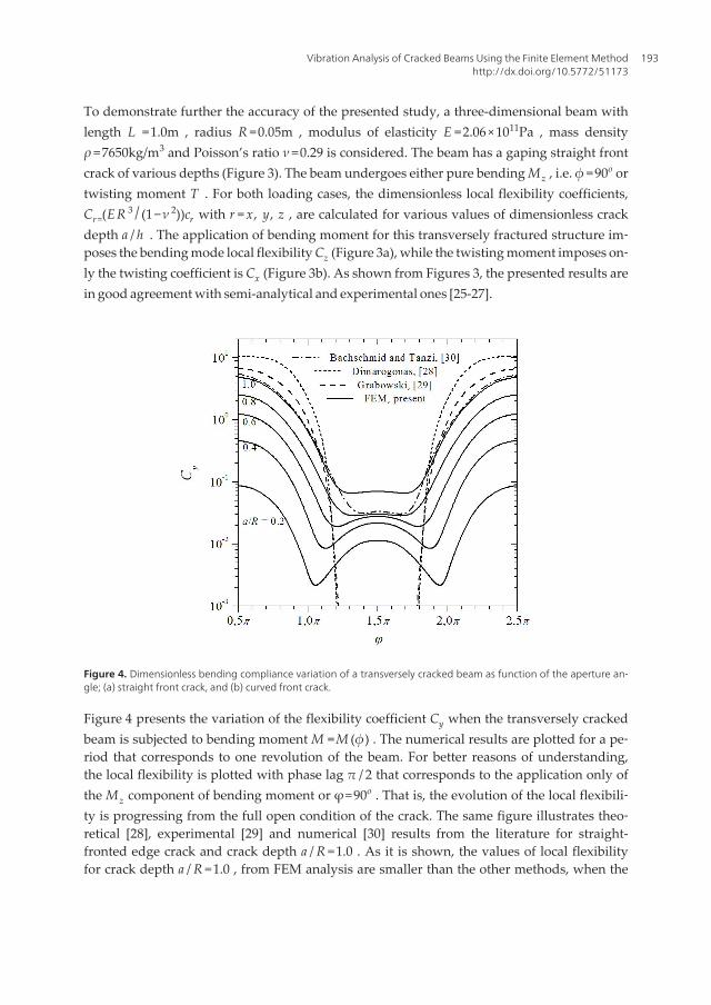
Figure 4. Dimensionless bending compliance variation of a transversely cracked beam as function of the aperture an‐gle; (a) straight front crack, and (b) curved front crack.
Figure 4 presents the variation of the flexibility coefficient Cy when the transversely crackedbeam is subjected to bending moment M =M (ϕ) . The numerical results are plotted for a pe‐riod that corresponds to one revolution of the beam. For better reasons of understanding,the local flexibility is plotted with phase lag π / 2 that corresponds to the application only ofthe Mz component of bending moment or φ=90o . That is, the evolution of the local flexibili‐ty is progressing from the full open condition of the crack. The same figure illustrates theo‐retical [28], experimental [29] and numerical [30] results from the literature for straight-fronted edge crack and crack depth a / R =1.0 . As it is shown, the values of local flexibilityfor crack depth a / R =1.0 , from FEM analysis are smaller than the other methods, when the
Vibration Analysis of Cracked Beams Using the Finite Element Methodhttp://dx.doi.org/10.5772/51173
193
crack is open. The experimental results are obtained for notched beam which is more flexi‐ble than the cracked beam. As the crack closes the FEM results are greater than the others.This is explained by the crack contact area (Figure 5), which differs and is generally smallerthan the area assumed by the theoretical approaches for the same edge orientation. The im‐possibility of these approximations to predict the crack closure correctly is the main reasonthat these yield comparable results with the present ones only on the regions of partiallyopening portion of the crack, i.e., between L c / L =0.5 or a / h =0.75 . The variation of the co‐efficient Cy depends significantly on the crack depth. For small crack depths, the crack doesnot open regularly once per revolution, but contact is observed twice per revolution. Thesecond contact state yields smaller compliance than the regular contact.
b. Crack contact state
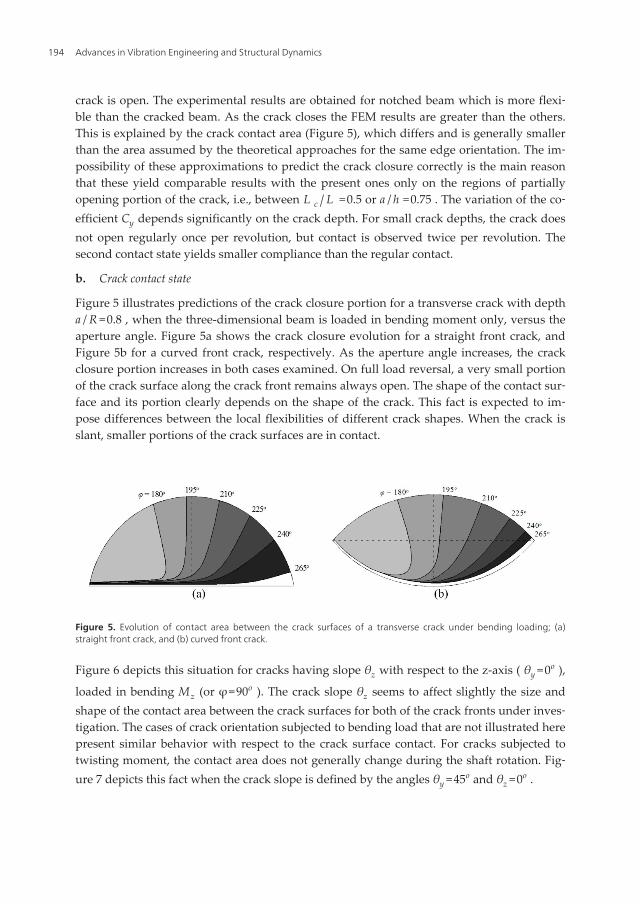
Figure 5 illustrates predictions of the crack closure portion for a transverse crack with deptha / R =0.8 , when the three-dimensional beam is loaded in bending moment only, versus theaperture angle. Figure 5a shows the crack closure evolution for a straight front crack, andFigure 5b for a curved front crack, respectively. As the aperture angle increases, the crackclosure portion increases in both cases examined. On full load reversal, a very small portionof the crack surface along the crack front remains always open. The shape of the contact sur‐face and its portion clearly depends on the shape of the crack. This fact is expected to im‐pose differences between the local flexibilities of different crack shapes. When the crack isslant, smaller portions of the crack surfaces are in contact.
Figure 5. Evolution of contact area between the crack surfaces of a transverse crack under bending loading; (a)straight front crack, and (b) curved front crack.
Figure 6 depicts this situation for cracks having slope θz with respect to the z-axis ( θy =0o ),
loaded in bending Mz (or φ=90o ). The crack slope θz seems to affect slightly the size andshape of the contact area between the crack surfaces for both of the crack fronts under inves‐tigation. The cases of crack orientation subjected to bending load that are not illustrated herepresent similar behavior with respect to the crack surface contact. For cracks subjected totwisting moment, the contact area does not generally change during the shaft rotation. Fig‐ure 7 depicts this fact when the crack slope is defined by the angles θy =45o and θz =0o .
Advances in Vibration Engineering and Structural Dynamics194
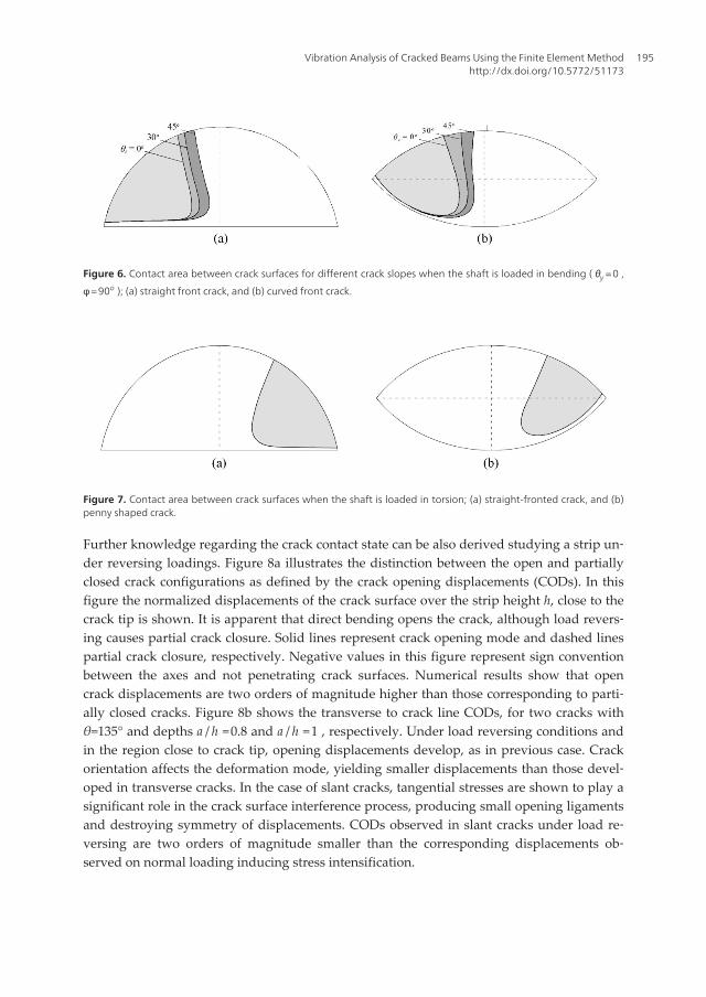
Figure 6. Contact area between crack surfaces for different crack slopes when the shaft is loaded in bending ( θy = 0 ,
φ = 90o ); (a) straight front crack, and (b) curved front crack.
Figure 7. Contact area between crack surfaces when the shaft is loaded in torsion; (a) straight-fronted crack, and (b)penny shaped crack.
Further knowledge regarding the crack contact state can be also derived studying a strip un‐der reversing loadings. Figure 8a illustrates the distinction between the open and partiallyclosed crack configurations as defined by the crack opening displacements (CODs). In thisfigure the normalized displacements of the crack surface over the strip height h, close to thecrack tip is shown. It is apparent that direct bending opens the crack, although load revers‐ing causes partial crack closure. Solid lines represent crack opening mode and dashed linespartial crack closure, respectively. Negative values in this figure represent sign conventionbetween the axes and not penetrating crack surfaces. Numerical results show that opencrack displacements are two orders of magnitude higher than those corresponding to parti‐ally closed cracks. Figure 8b shows the transverse to crack line CODs, for two cracks withθ=135° and depths a / h =0.8 and a / h =1 , respectively. Under load reversing conditions andin the region close to crack tip, opening displacements develop, as in previous case. Crackorientation affects the deformation mode, yielding smaller displacements than those devel‐oped in transverse cracks. In the case of slant cracks, tangential stresses are shown to play asignificant role in the crack surface interference process, producing small opening ligamentsand destroying symmetry of displacements. CODs observed in slant cracks under load re‐versing are two orders of magnitude smaller than the corresponding displacements ob‐served on normal loading inducing stress intensification.
Vibration Analysis of Cracked Beams Using the Finite Element Methodhttp://dx.doi.org/10.5772/51173
195
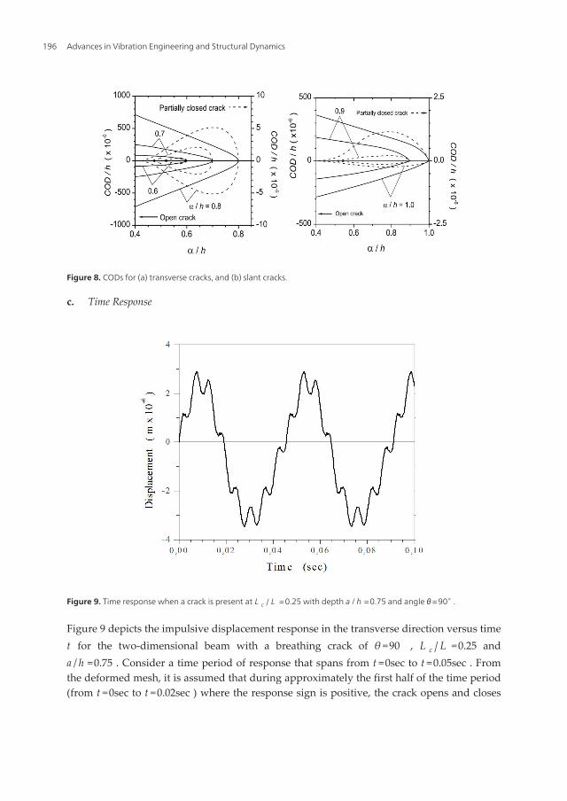
Figure 8. CODs for (a) transverse cracks, and (b) slant cracks.
c. Time Response
Figure 9. Time response when a crack is present at L c / L = 0.25 with depth a /h = 0.75 and angle θ= 90∘ .
Figure 9 depicts the impulsive displacement response in the transverse direction versus timet for the two-dimensional beam with a breathing crack of θ =90 , L c / L =0.25 anda / h =0.75 . Consider a time period of response that spans from t =0sec to t =0.05sec . Fromthe deformed mesh, it is assumed that during approximately the first half of the time period(from t =0sec to t =0.02sec ) where the response sign is positive, the crack opens and closes
Advances in Vibration Engineering and Structural Dynamics196
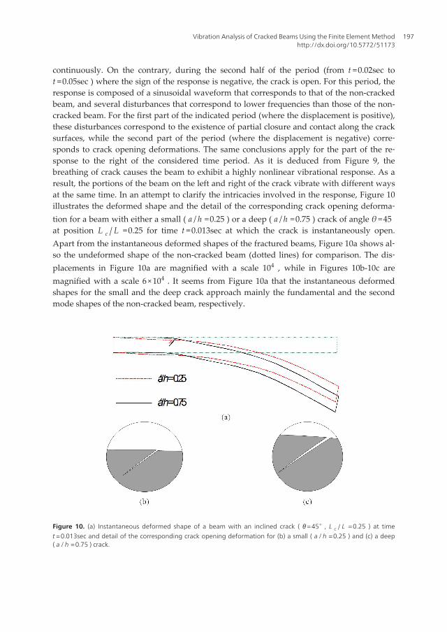
continuously. On the contrary, during the second half of the period (from t =0.02sec tot =0.05sec ) where the sign of the response is negative, the crack is open. For this period, theresponse is composed of a sinusoidal waveform that corresponds to that of the non-crackedbeam, and several disturbances that correspond to lower frequencies than those of the non-cracked beam. For the first part of the indicated period (where the displacement is positive),these disturbances correspond to the existence of partial closure and contact along the cracksurfaces, while the second part of the period (where the displacement is negative) corre‐sponds to crack opening deformations. The same conclusions apply for the part of the re‐sponse to the right of the considered time period. As it is deduced from Figure 9, thebreathing of crack causes the beam to exhibit a highly nonlinear vibrational response. As aresult, the portions of the beam on the left and right of the crack vibrate with different waysat the same time. In an attempt to clarify the intricacies involved in the response, Figure 10illustrates the deformed shape and the detail of the corresponding crack opening deforma‐tion for a beam with either a small ( a / h =0.25 ) or a deep ( a / h =0.75 ) crack of angle θ =45at position L c / L =0.25 for time t =0.013sec at which the crack is instantaneously open.Apart from the instantaneous deformed shapes of the fractured beams, Figure 10a shows al‐so the undeformed shape of the non-cracked beam (dotted lines) for comparison. The dis‐placements in Figure 10a are magnified with a scale 104 , while in Figures 10b-10c aremagnified with a scale 6×10⁴ . It seems from Figure 10a that the instantaneous deformedshapes for the small and the deep crack approach mainly the fundamental and the secondmode shapes of the non-cracked beam, respectively.
Figure 10. (a) Instantaneous deformed shape of a beam with an inclined crack ( θ= 45∘ , L c / L = 0.25 ) at timet = 0.013sec and detail of the corresponding crack opening deformation for (b) a small ( a /h = 0.25 ) and (c) a deep( a /h = 0.75 ) crack.
Vibration Analysis of Cracked Beams Using the Finite Element Methodhttp://dx.doi.org/10.5772/51173
197
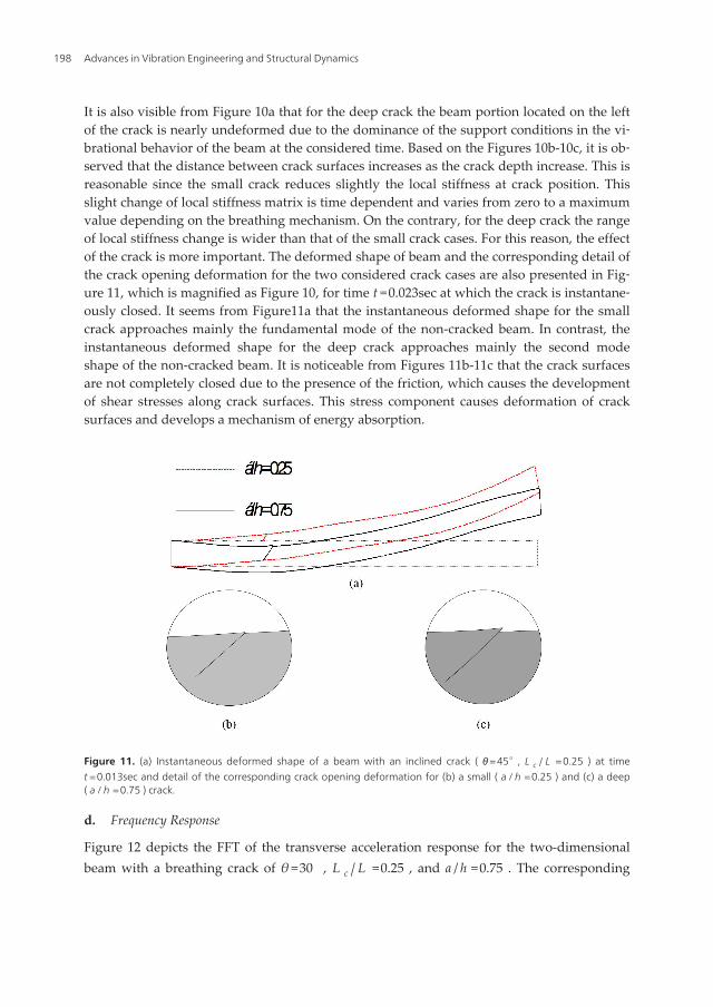
It is also visible from Figure 10a that for the deep crack the beam portion located on the leftof the crack is nearly undeformed due to the dominance of the support conditions in the vi‐brational behavior of the beam at the considered time. Based on the Figures 10b-10c, it is ob‐served that the distance between crack surfaces increases as the crack depth increase. This isreasonable since the small crack reduces slightly the local stiffness at crack position. Thisslight change of local stiffness matrix is time dependent and varies from zero to a maximumvalue depending on the breathing mechanism. On the contrary, for the deep crack the rangeof local stiffness change is wider than that of the small crack cases. For this reason, the effectof the crack is more important. The deformed shape of beam and the corresponding detail ofthe crack opening deformation for the two considered crack cases are also presented in Fig‐ure 11, which is magnified as Figure 10, for time t =0.023sec at which the crack is instantane‐ously closed. It seems from Figure11a that the instantaneous deformed shape for the smallcrack approaches mainly the fundamental mode of the non-cracked beam. In contrast, theinstantaneous deformed shape for the deep crack approaches mainly the second modeshape of the non-cracked beam. It is noticeable from Figures 11b-11c that the crack surfacesare not completely closed due to the presence of the friction, which causes the developmentof shear stresses along crack surfaces. This stress component causes deformation of cracksurfaces and develops a mechanism of energy absorption.
Figure 11. (a) Instantaneous deformed shape of a beam with an inclined crack ( θ= 45∘ , L c / L = 0.25 ) at timet = 0.013sec and detail of the corresponding crack opening deformation for (b) a small ( a /h = 0.25 ) and (c) a deep( a /h = 0.75 ) crack.
d. Frequency Response
Figure 12 depicts the FFT of the transverse acceleration response for the two-dimensionalbeam with a breathing crack of θ =30 , L c / L =0.25 , and a / h =0.75 . The corresponding
Advances in Vibration Engineering and Structural Dynamics198
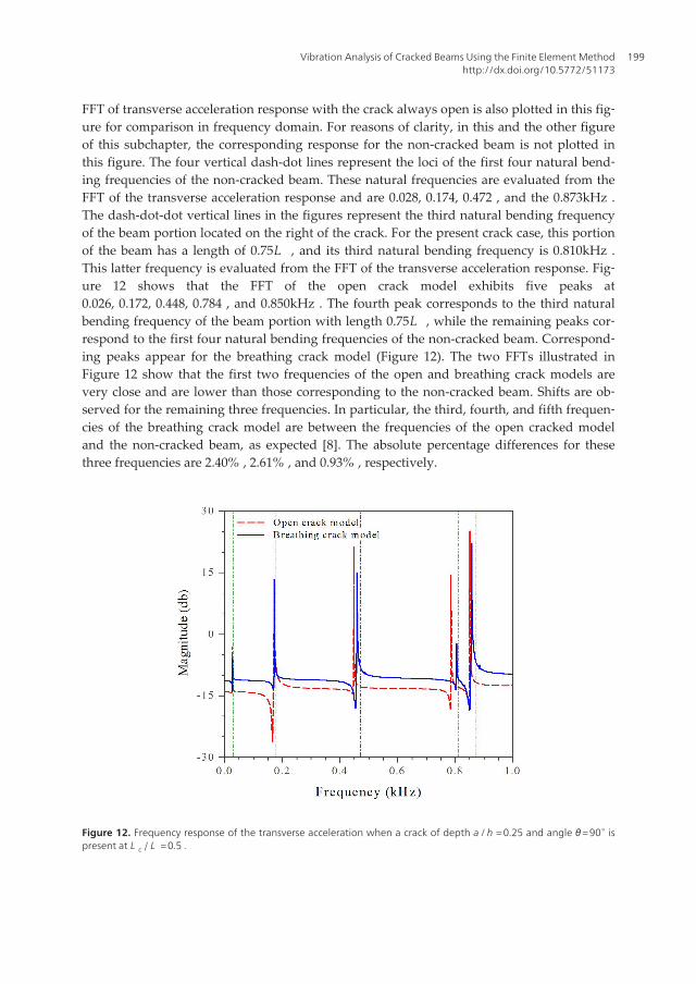
FFT of transverse acceleration response with the crack always open is also plotted in this fig‐ure for comparison in frequency domain. For reasons of clarity, in this and the other figureof this subchapter, the corresponding response for the non-cracked beam is not plotted inthis figure. The four vertical dash-dot lines represent the loci of the first four natural bend‐ing frequencies of the non-cracked beam. These natural frequencies are evaluated from theFFT of the transverse acceleration response and are 0.028, 0.174, 0.472 , and the 0.873kHz .The dash-dot-dot vertical lines in the figures represent the third natural bending frequencyof the beam portion located on the right of the crack. For the present crack case, this portionof the beam has a length of 0.75L , and its third natural bending frequency is 0.810kHz .This latter frequency is evaluated from the FFT of the transverse acceleration response. Fig‐ure 12 shows that the FFT of the open crack model exhibits five peaks at0.026, 0.172, 0.448, 0.784 , and 0.850kHz . The fourth peak corresponds to the third naturalbending frequency of the beam portion with length 0.75L , while the remaining peaks cor‐respond to the first four natural bending frequencies of the non-cracked beam. Correspond‐ing peaks appear for the breathing crack model (Figure 12). The two FFTs illustrated inFigure 12 show that the first two frequencies of the open and breathing crack models arevery close and are lower than those corresponding to the non-cracked beam. Shifts are ob‐served for the remaining three frequencies. In particular, the third, fourth, and fifth frequen‐cies of the breathing crack model are between the frequencies of the open cracked modeland the non-cracked beam, as expected [8]. The absolute percentage differences for thesethree frequencies are 2.40% , 2.61% , and 0.93% , respectively.
Figure 12. Frequency response of the transverse acceleration when a crack of depth a /h = 0.25 and angle θ= 90∘ ispresent at L c / L = 0.5 .
Vibration Analysis of Cracked Beams Using the Finite Element Methodhttp://dx.doi.org/10.5772/51173
199
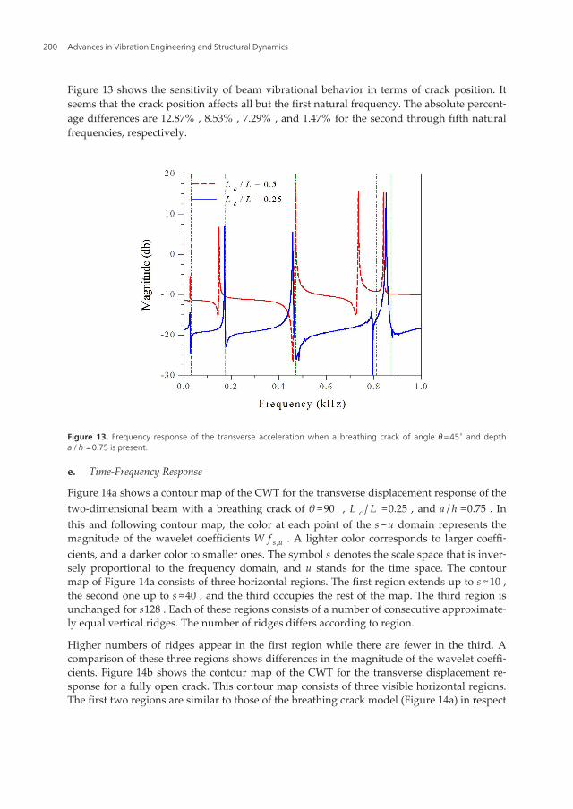
Figure 13 shows the sensitivity of beam vibrational behavior in terms of crack position. Itseems that the crack position affects all but the first natural frequency. The absolute percent‐age differences are 12.87% , 8.53% , 7.29% , and 1.47% for the second through fifth naturalfrequencies, respectively.
Figure 13. Frequency response of the transverse acceleration when a breathing crack of angle θ= 45∘ and deptha /h = 0.75 is present.
e. Time-Frequency Response
Figure 14a shows a contour map of the CWT for the transverse displacement response of thetwo-dimensional beam with a breathing crack of θ =90 , L c / L =0.25 , and a / h =0.75 . Inthis and following contour map, the color at each point of the s −u domain represents themagnitude of the wavelet coefficients W f s ,u . A lighter color corresponds to larger coeffi‐cients, and a darker color to smaller ones. The symbol s denotes the scale space that is inver‐sely proportional to the frequency domain, and u stands for the time space. The contourmap of Figure 14a consists of three horizontal regions. The first region extends up to s ≈10 ,the second one up to s ≈40 , and the third occupies the rest of the map. The third region isunchanged for s128 . Each of these regions consists of a number of consecutive approximate‐ly equal vertical ridges. The number of ridges differs according to region.
Higher numbers of ridges appear in the first region while there are fewer in the third. Acomparison of these three regions shows differences in the magnitude of the wavelet coeffi‐cients. Figure 14b shows the contour map of the CWT for the transverse displacement re‐sponse for a fully open crack. This contour map consists of three visible horizontal regions.The first two regions are similar to those of the breathing crack model (Figure 14a) in respect
Advances in Vibration Engineering and Structural Dynamics200
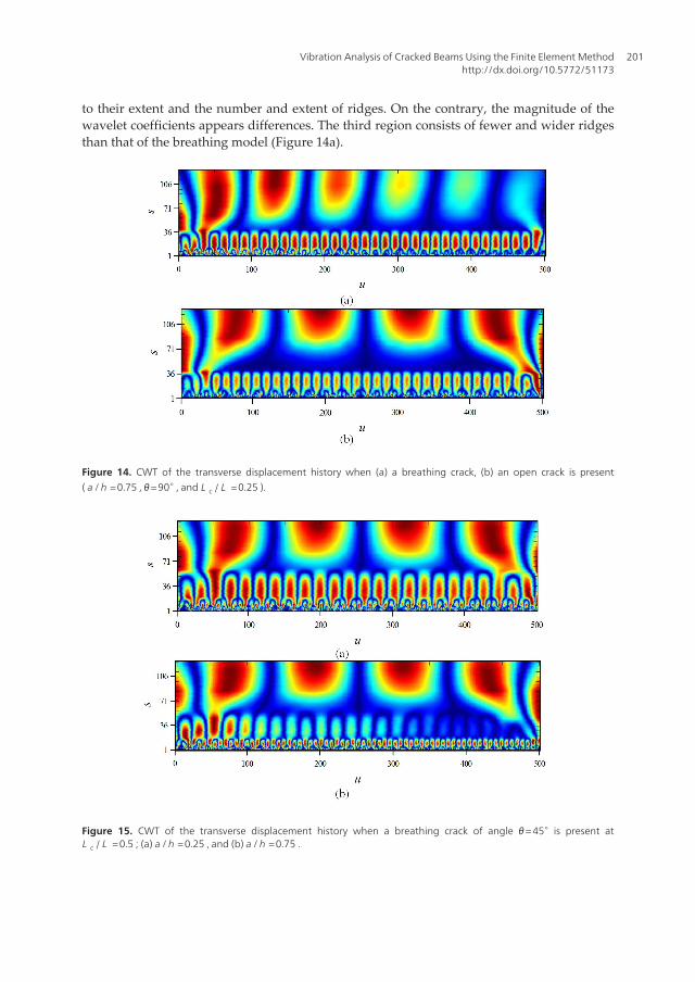
to their extent and the number and extent of ridges. On the contrary, the magnitude of thewavelet coefficients appears differences. The third region consists of fewer and wider ridgesthan that of the breathing model (Figure 14a).
Figure 14. CWT of the transverse displacement history when (a) a breathing crack, (b) an open crack is present( a /h = 0.75 , θ= 90∘ , and L c / L = 0.25 ).
Figure 15. CWT of the transverse displacement history when a breathing crack of angle θ= 45∘ is present atL c / L = 0.5 ; (a) a /h = 0.25 , and (b) a /h = 0.75 .
Vibration Analysis of Cracked Beams Using the Finite Element Methodhttp://dx.doi.org/10.5772/51173
201
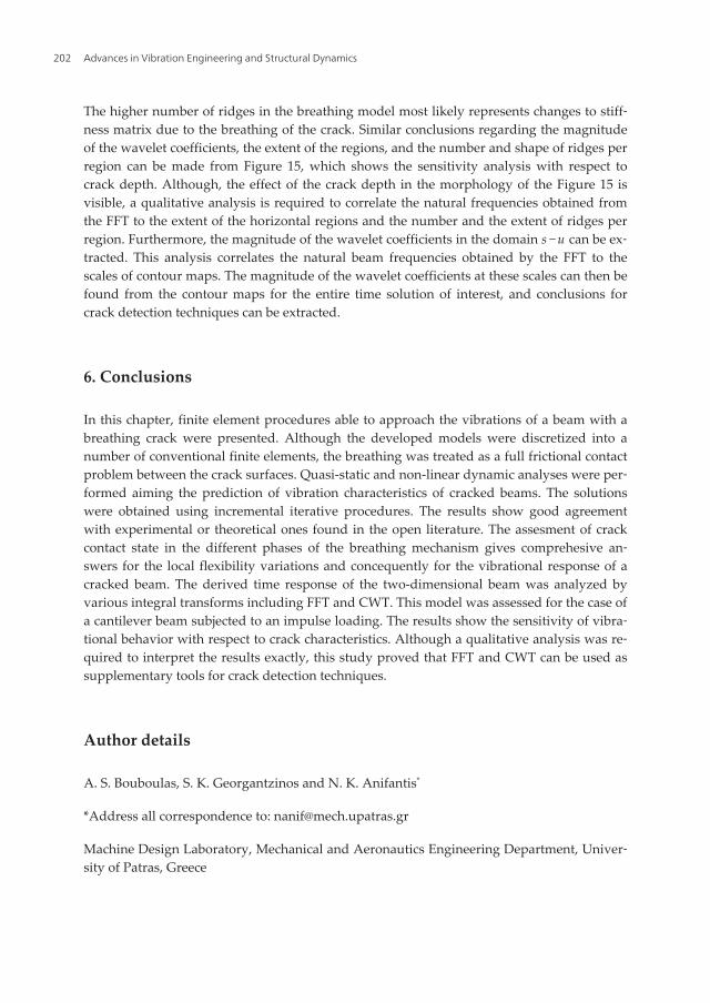
The higher number of ridges in the breathing model most likely represents changes to stiff‐ness matrix due to the breathing of the crack. Similar conclusions regarding the magnitudeof the wavelet coefficients, the extent of the regions, and the number and shape of ridges perregion can be made from Figure 15, which shows the sensitivity analysis with respect tocrack depth. Although, the effect of the crack depth in the morphology of the Figure 15 isvisible, a qualitative analysis is required to correlate the natural frequencies obtained fromthe FFT to the extent of the horizontal regions and the number and the extent of ridges perregion. Furthermore, the magnitude of the wavelet coefficients in the domain s −u can be ex‐tracted. This analysis correlates the natural beam frequencies obtained by the FFT to thescales of contour maps. The magnitude of the wavelet coefficients at these scales can then befound from the contour maps for the entire time solution of interest, and conclusions forcrack detection techniques can be extracted.
6. Conclusions
In this chapter, finite element procedures able to approach the vibrations of a beam with abreathing crack were presented. Although the developed models were discretized into anumber of conventional finite elements, the breathing was treated as a full frictional contactproblem between the crack surfaces. Quasi-static and non-linear dynamic analyses were per‐formed aiming the prediction of vibration characteristics of cracked beams. The solutionswere obtained using incremental iterative procedures. The results show good agreementwith experimental or theoretical ones found in the open literature. The assesment of crackcontact state in the different phases of the breathing mechanism gives comprehesive an‐swers for the local flexibility variations and concequently for the vibrational response of acracked beam. The derived time response of the two-dimensional beam was analyzed byvarious integral transforms including FFT and CWT. This model was assessed for the case ofa cantilever beam subjected to an impulse loading. The results show the sensitivity of vibra‐tional behavior with respect to crack characteristics. Although a qualitative analysis was re‐quired to interpret the results exactly, this study proved that FFT and CWT can be used assupplementary tools for crack detection techniques.
Author details
A. S. Bouboulas, S. K. Georgantzinos and N. K. Anifantis*
*Address all correspondence to: [email protected]
Machine Design Laboratory, Mechanical and Aeronautics Engineering Department, Univer‐sity of Patras, Greece
Advances in Vibration Engineering and Structural Dynamics202
References
[1] Silva, J. M. M., & Gomes, A. J. M. A. (1990). Experimental dynamic analysis ofcracked free-free beams. Experimental Mechanics, 30, 20-25.
[2] Doebling, S. W., Farrar, C. R., Prime, M. B., & Shevitz, D. W. (1998). A summary re‐view of vibration based damage identification methods. The Shock and Vibration Di‐gest, 30, 91-105.
[3] Christides, S., & Barr, A. D. S. (1984). One-dimensional theory of cracked Bernoulli-Euler beams. International Journal of Mechanical Sciences, 26, 639-648.
[4] Dimarogonas, A. D. (1976). Vibration Engineering, West Publishers, St Paul, Minesota.
[5] Chondros, T. G., & Dimarogonas, A. D. (1980). Identification of cracks in weldedjoints of complex structures. Journal of Sound and Vibration, 69, 531-538.
[6] Krawczuk, M., Żak, A., & Ostachowicz, W. (2000). Elastic beam finite element with atransverse elasto-plastic crack. Finite Elements in Analysis and Design, 34, 61-73.
[7] Bouboulas, A. S., & Anifantis, N. K. (2008). Formulation of cracked beam element foranalysis of fractured skeletal structures. Engineering Structures, 30, 894-901.
[8] Gudmundson, P. (1983). The dynamic behavior of slender structures with cross-sec‐tional cracks. Journal of the Mechanics and Physics of Solids, 31, 329-345.
[9] Cacciola, P., & Muscolino, G. (2002). Dynamic response of a rectangular beam with aknown non-propagating crack of certain or uncertain depth. Computers and Struc‐tures, 80, 2387-2396.
[10] Benfratello, S., Cacciola, P., Impollonia, N., Masnata, A., & Muscolino, G. (2007). Nu‐merical and experimental verification of a technique for locating a fatigue crack onbeams vibrating under Gaussian excitation. Engineering Fracture Mechanics, 74,2992-3001.
[11] Sholeh, K., Vafai, A., & Kaveh, A. (2007). Online detection of the breathing crack us‐ing an adaptive tracking technique. Acta Mechanica, 188, 139-154.
[12] Clark, R., Dover, W. D., & Bond, L. J. (1987). The effect of crack closure on the relia‐bility of NDT predictions of crack size. NDT International, 20, 269-275.
[13] Abraham, O. N. L., & Brandon, J. A. (1995). The modelling of the opening and clo‐sure of a crack. Journal of Vibration and Acoustics, 117, 370-377.
[14] Douka, E., & Hadjileontiadis, L. J. (2005). Time-frequency analysis of the free vibra‐tion response of a beam with a breathing crack. NDT&E International, 38, 3-10.
[15] Loutridis, S., Douka, E., & Hadjileontiadis, L. J. (2005). Forced vibration behaviourand crack detection of cracked beams using instantaneous frequency. NDT&E Inter‐national, 38, 411-419.
Vibration Analysis of Cracked Beams Using the Finite Element Methodhttp://dx.doi.org/10.5772/51173
203
[16] Andrieux, S., & Varé, C. (2002). A 3D cracked beam model with unilateral contact.Application to rotors. European Journal of Mechanics A/Solids, 21, 793-810.
[17] Nandi, A., & Neogy, S. (2002). Modelling of a beam with a breathing edge crack andsome observations for crack detection. Journal of Vibration and Control, 8, 673-693.
[18] Andreaus, U., Casini, P., & Vestroni, F. (2007). Nonlinear dynamics of a cracked can‐tilever beam under harmonic excitation. International Journal of Nonlinear Mechanics,42, 566-575.
[19] Bachschmid, N., Tanzi, E., & Audebert, S. (2008). The effect of helicoidal cracks onthe behavior of rotating shafts. Engineering Fracture Mechanics, 75, 475-488.
[20] Bathe, K. J. (1996). Finite Element Procedures, Prentice-Hall, Upper Saddle River, NJ.
[21] Brigham, E. O. (1973). The Fast Fourier Transform: An Introduction to Its Theory and Ap‐plication, Englewood Cliffs, NJ, Prentice Hall.
[22] Rao, R. M., & Bopardikar, A. S. (1998). Wavelet transforms- introduction to theory andapplications, Reading, MA, Addison Wesley Longman.
[23] Nandwana, B. P., & Maiti, S. K. (1997). Modelling of vibration of beam in presence ofinclined edge or internal crack for its possible detection based on frequency measure‐ments. Engineering Fracture Mechanics, 5, 193-205.
[24] Kisa, M., & Brandon, J. (2000). The effects of closure of cracks on the dynamics of acracked cantilever beam. Journal of Sound and Vibration, 238, 1-18.
[25] Chasalevris, A. C., & Papadopoulos, C. A. (2006). Identification of multiple cracks inbeams under bending. Mechanical Systems and Signal Processing, 20, 1631-1673.
[26] Bush, A. J. (1976). Experimentally determined stress-intensity factors for single-edge-crack round bars loaded in bending. Experimental Mechanics, 16-249.
[27] Zou, J., Chen, J., & Pu, Y. P. (2004). Wavelet time-frequency analysis of torsional vi‐brations in rotor system with a transverse crack. Computers and Structures, 82,1181-1187.
[28] Dimarogonas, A. D., & Papadopoulos, C. A. (1983). Vibration of cracked shaft inbending. Journal of Sound and Vibration, 91, 583-593.
[29] Grabowski, B. (1979). The vibrational behavior of a turbine rotor containing a trans‐verse crack. ASME Design Engineering Technology Conference [79-DET], Paper.
[30] Bachschmid, N., & Tanzi, E. (2004). Deflections and strains in cracked shafts due torotating loads: a numerical and experimental analysis. International Journal of RotatingMachinery, 10, 283-291.
Advances in Vibration Engineering and Structural Dynamics204