Embed Size (px)
Citation preview
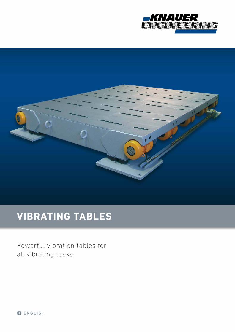
Powerful vibration tables for all vibrating tasks
VIBRATING TABLES
ENGLISH
2
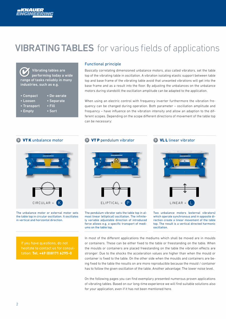
VT P pendulum vibrator
The pendulum vibrator sets the table top in al-most linear (elliptical) oscillation. The infinite-ly variable adjustable direction of introduced force allows e.g. a specific transport of medi-ums on the table top.
VL L linear vibrator
Two unbalance motors (external vibrators) which operate synchronous and in opposite di-rection create a linear movement of the table top. The result is a vertical directed harmonic oscillation.
VT K unbalance motor
The unbalance motor or external motor sets the table top in circular oscillation. It oscillates in vertical and horizontal direction.
Functional principle
Basically correlating dimensioned unbalance motors, also called vibrators, set the table
top of the vibrating table in oscillation. A vibration isolating elastic support between table
top and base frame of the vibrating table avoid that unwanted vibrations will get into the
base frame and as a result into the floor. By adjusting the unbalances on the unbalance
motors during standstill the oscillation amplitude can be adapted to the application.
When using an electric control with frequency inverter furthermore the vibration fre-
quency can be changed during operation. Both parameter – oscillation amplitude and
frequency – have influence on the vibration intensity and allow an adaption to the dif-
ferent scopes. Depending on the scope different directions of movement of the table top
can be necessary:
VIBRATING TABLES for various fields of applications
Vibrating tables are performing today a wide range of tasks reliably in many industries, such as e.g.
• Compact • De-aerate• Loosen • Separate • Transport • Fill• Empty • Sort
In most of the different applications the mediums which shall be moved are in moulds
or containers. These can be either fixed to the table or freestanding on the table. When
the moulds or containers are placed freestanding on the table the vibration effects are
stronger: Due to the shocks the acceleration values are higher than when the mould or
container is fixed to the table. On the other side when the moulds and containers are be-
ing fixed to the table the results on are more reproducible because the mould / container
has to follow the given oscillation of the table. Another advantage: The lower noise level.
On the following pages you can find exemplary presented numerous proven applications
of vibrating tables. Based on our long-time experience we will find suitable solutions also
for your application, even if it has not been mentioned here.
4
CIRCUL A R = EL IP T IC A L = L INE A R =
If you have questions, do not hesitate to contact us for consul-tation: Tel. +49 (0)8171 6295-0
K P L

3
P O W E R F U L V I B R AT I O N TA B L E S F O R A L L V I B R AT I N G TA S K S
Length 400 mm
Width 400 mm
Height 350 mm
Oscillation frequency 50 Hz
Centrifugal force max. 6 kN
Movement
Length 700 mm
Width 700 mm
Height 350 mm
Oscillation frequency 30 – 100 Hz
Centrifugal force max. 20 kN
Movement
Length 1200 mm
Width 800 mm
Height 750 mm
Oscillation frequency 30 – 100 Hz
Centrifugal force max. 40 kN
Movement
VIBRATING TABLES for various fields of applications VIBRATING TABLE standard
VT 4.4 6P
Vibrating table with elliptical movement of
the table surface, e.g. for the production of
small concrete elements. Available with or
without mounting option for the mould.
VT 7.7 20K
Vibrating table with circular movement of
the table surface, e.g. for the production of
small concrete elements. Available with or
without mounting option for the mould.
VT 12.8 40L
Vibrating table with vertical movement of
the table surface, e.g. for the production of
small concrete elements. Available with or
without mounting option for the mould.
L
L
L
L
L
L
L
L
K
K
K
K
K
K
P
P
P
P
P
P
Type Dimensions Movement Max. Load Oscillation frequency Centrifugal force
VT 4.4 400 x 400 mm 50 kg 20 – 50 / 100 Hz 6 – 10 kN
VT 5.5 500 x 500 mm 50 kg 20 – 50 / 100 Hz 6 – 20 kN
VT 7.7 700 x 700 mm 200 kg 20 – 50 / 100 Hz 24 – 40 kN
VT 8.8 800 x 800 mm 400 kg 20 – 50 / 100 Hz 24 – 40 kN
VT 10.10 1000 x 1000 mm 500 kg 20 – 50 / 100 Hz 24 – 40 kN
VT 12.5 1200 x 500 mm 500 kg 20 – 50 / 100 Hz 24 – 40 kN
VT 12.8 1200 x 800 mm 500 kg 20 – 50 / 100 Hz 24 – 40 kN
VT 20.15 2000 x 1500 mm 1000 kg 20 – 50 / 100 Hz 48 – 80 kN
VT 30.15 3000 x 1500 mm 1000 kg 20 – 50 / 100 Hz 48 – 80 kN

4
VIBRATING TABLES for concrete elements
VT 56.6 280L
Vibrating table with vertical movement of
the table surface e.g. For the production
on concrete floor elements for pigpens.
Available with or without mounting option
(hydraulic clamps) for the mould.
VT 40.40 720L
Vibrating table with vertical movement of
the table surface e.g. for the production of
large concrete elements, with mounting
option (hydraulic clamps) for the mould.
VT 32.31 352L
Vibrating table with vertical movement of
the table surface e.g. for the production of
large concrete pipes, with mounting option
(hydraulic clamps) for the mould.
Length 500 mm
Width 600 mm
Height 665 mm
Oscillation frequency 30 – 80 Hz
Centrifugal force max. 280 kN
Movement
Length 4000 mm
Width 4000 mm
Height 940 mm
Oscillation frequency 30 – 80 Hz
Centrifugal force max. 720 kN
Movement
Length 3200 mm
Width 3100 mm
Height 1030 mm
Oscillation frequency 30 – 80 Hz
Centrifugal force max. 352 kN
Movement
5
P O W E R F U L V I B R AT I O N TA B L E S F O R A L L V I B R AT I N G TA S K S
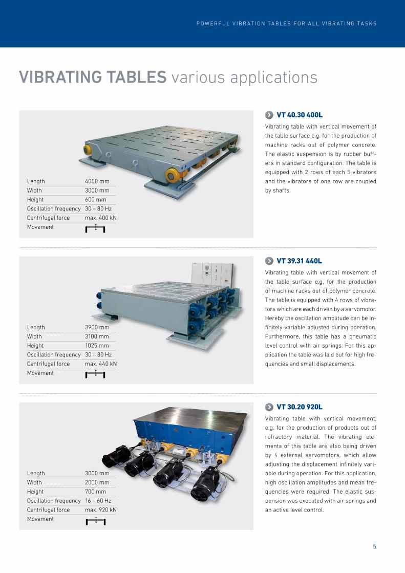
VIBRATING TABLES various applications
VT 40.30 400L
Vibrating table with vertical movement of
the table surface e.g. for the production of
machine racks out of polymer concrete.
The elastic suspension is by rubber buff-
ers in standard configuration. The table is
equipped with 2 rows of each 5 vibrators
and the vibrators of one row are coupled
by shafts.
VT 39.31 440L
Vibrating table with vertical movement of
the table surface e.g. for the production
of machine racks out of polymer concrete.
The table is equipped with 4 rows of vibra-
tors which are each driven by a servomotor.
Hereby the oscillation amplitude can be in-
finitely variable adjusted during operation.
Furthermore, this table has a pneumatic
level control with air springs. For this ap-
plication the table was laid out for high fre-
quencies and small displacements.
VT 30.20 920L
Vibrating table with vertical movement,
e.g. for the production of products out of
refractory material. The vibrating ele-
ments of this table are also being driven
by 4 external servomotors, which allow
adjusting the displacement infinitely vari-
able during operation. For this application,
high oscillation amplitudes and mean fre-
quencies were required. The elastic sus-
pension was executed with air springs and
an active level control.
Length 3000 mm
Width 2000 mm
Height 700 mm
Oscillation frequency 16 – 60 Hz
Centrifugal force max. 920 kN
Movement
Length 3900 mm
Width 3100 mm
Height 1025 mm
Oscillation frequency 30 – 80 Hz
Centrifugal force max. 440 kN
Movement
Length 4000 mm
Width 3000 mm
Height 600 mm
Oscillation frequency 30 – 80 Hz
Centrifugal force max. 400 kN
Movement

6
VIBRATING BEAMS
Length 1900 mm
Width 500 mm
Height 780 mm
Oscillation frequency 30 – 80 Hz
Centrifugal force max. 50 kN
Movement
Length 1450 mm
Width 500 mm
Height 800 mm
Oscillation frequency 30 – 100 Hz
Centrifugal force max. 40 kN
Movement
Length 1140 mm
Width 300 mm
Height 600 mm
Oscillation frequency 30 – 100 Hz
Centrifugal force max. 20 kN
Movement
VB 19.5 50L
Vibrating beams with vertical movement,
e.g. for the production of railway sleepers
out of concrete, without mounting option
for the mould (free riding). The vibrating
beams have an elastic suspension with
rubber buffers in a special configuration
(turned by 90°).
VB 15.5 40L
By setting up several vibrating beams next
to each other you will get a vibrating sta-
tion for a long mould bracket as they are
being used e.g. in the production of slat-
ted floors. The support plates are out of
Vulkollan and are damping the noise gen-
eration from the free riding mould bracket.
VB 11.3 20L
Vibrating beams with vertical movements,
e.g. for the production of noise barrier el-
ements out of concrete, with mounting
option (hydraulic clamps) for the moulds.
The vibrating beams have an elastic sus-
pension with rubber buffers in standard
configuration.
7
P O W E R F U L V I B R AT I O N TA B L E S F O R A L L V I B R AT I N G TA S K S
VIBRATING FRAMES
Length 1200 mm
Width 1200 mm
Height 400 mm
Oscillation frequency 15 – 30 Hz
Centrifugal force max. 50 kN
Movement
Length 1200 mm
Width 1200 mm
Height 365 mm
Oscillation frequency 15 – 50 Hz
Centrifugal force max. 32 kN
Movement
Length 1800 mm
Width 1200 mm
Height 800 mm
Oscillation frequency 15 – 50 Hz
Centrifugal force max. 20 kN
Movement
VF 18.12 20L
Vibrating frame with directed oscilla-
tion for emptying cardboard boxes with
bulk material (material transport in one
corner). Easy loading and unloading with
a pallet jack possible.
VF 12.12 32L
Vibrating frame with vertical oscillation at
medium frequencies and amplitude for the
compaction of bulk material in Big Bags. By
adjusting the bracket, pallets of several dif-
ferent sizes can be securely placed on the
frame.
VF 12.12 50L
Vibrating frame with vertical oscillation
at lower frequencies and big amplitude
for the compaction of bulk material in Big
Bags. By adjusting the bracket, pallets of
several different sizes can be securely
placed on the frame.

P O W E R F U L V I B R AT I O N TA B L E S F O R A L L V I B R AT I N G TA S K S
Details Hydraulic mould clamps
For the fast and easy fixation of the mould to the table, hydraulic clamps are ideally
suited. A massive design and vibration resistant, strong hydraulic cylinder guarantee
even under high G-forces a secure connection between mould and table.
Vibrator coupling
Vibrators mounted in one row should be coupled by shafts, to be able to introduce in
phase centrifugal forces in different areas of the vibrating table. Only then, a harmon-
ic vibration of the table is assured.
Pneumatic suspension / Level control
Besides rubber buffers often air bellows are being used for the elastic suspension.
These have the advantage of lower resonance frequencies and further more they can
be activated and controlled by valves and sensors in that way, that severe unsymmet-
rical load on the table can be compensated.
Power supply and control
Depending on the application different requirements are asked for the control of the
vibrating table, e.g. additional level control, remote control, hydraulic clamping ect.
Since KNAUER ENGINEERING itself plans, produces and furthermore programs the
controls, individual requirements can be implemented fast and at low cost.
Knauer Engineering GmbH Industrieanlagen & Co. KG
Elbestraße 11 – 13 · D-82538 Geretsried · Germany
Tel.: +49 (0) 8171 62950 · Fax: +49 (0) 8171 64545
E-Mail: [email protected] · Web: www.knauer.de
We reserve the right to introduce modifications rendered necessary in the course of further technological development
© 2016 KNAUER Engineering