Embed Size (px)
Citation preview
Water and Sewer PO Box 330316 • 3071 SW 38 Avenue
Miami, Florida 33233-0316 T 305-665-7471
miamidade.gov
VIA ELECTRONIC CORRESPONDENCE April 2, 2015 CCN: 59265 File No: 8.DC.20.19
Chief, Environmental Enforcement Section Environment and Natural Resources Division U.S. Department of Justice P.O. Box 7611 Ben Franklin Station Washington, D.C. 20044-7611 RE: DOJ No. 90-5-1-1-4022/1 [email protected]
Chief, Clean Water Enforcement Branch Water Protection Division Attn: Brad Ammons U.S. Environmental Protection Agency, Region 4 61 Forsyth Street, S.W. Atlanta, Georgia 30303 [email protected]
Rachael Amy Kamons Environmental Enforcement Section U.S. Department of Justice P.O. Box 7611 Ben Franklin Station Washington, D.C. 20044-7611 [email protected]
Florida Department of Environmental Protection Southeast District – Suite 200 400 N. Congress Ave. West Palm Beach, FL 33401 Attn: Compliance/Enforcement Section [email protected]
RE: Consent Decree (Case: No. 1:12-cv-24400-FAM) Reference DOJ Case No. 90-5-1-1-4022/1
Section VI – Pump Station Operations and Preventative Maintenance Program Submittal, Paragraph 19(f)
Dear Sir/Madam: In accordance with the provisions of Paragraph 19 (f) of the above referenced Consent Decree, on behalf of Miami-Dade County, the Miami-Dade Water and Sewer Department (MDWASD) submits to the United States Environmental Protection Agency (EPA) and the State of Florida Department of Environmental Protection (FDEP) the Pump Station Operations and Preventative Maintenance Program. I certify under penalty of law that this document and all attachments were prepared under my direction or supervision in accordance with a system designed to assure that qualified personnel properly gather and evaluate the information submitted. Based on my inquiry of the person or persons who manage the system, or those persons directly responsible for gathering such information, the information submitted is, to the best of my knowledge and belief, true, accurate and complete. I am aware that there are significant penalties for submitting false information, including the possibility of fine and imprisonment for knowing violations.
Paragraph 19(f), Consent Decree Pump Station Operations and Preventative Maintenance Program April 2, 2015 Page 3
Jack Osterholt Director, Miami-Dade Regulatory and Economic Resources 111 NW 1st St 29th Floor Miami, FL 33128
[email protected] Robert A. Cuevas, Jr. Miami-Dade County Attorney 111 NW First Street Suite 2810 Miami, Florida 33128
William Bush Associate Regional Counsel U.S. EPA, Region 4 61 Forsyth Street, SW Atlanta, Georgia 30303 [email protected] William A. Weinischke Senior Trial Attorney Environmental Enforcement Section Environment and Natural Resources Division U.S. Department of Justice P.O. Box 7611 Washington, D.C. 20044 [email protected]
CMOM Program Pump Station Operations & Preventative Maintenance Program April 2, 2015 Prepared by The Miami-Dade County Water and Sewer Department and the Consent Decree CMOM Program Team Prepared for United States Environmental Protection Agency and Florida Department of Environmental Protection

THIS PAGE LEFT INTENTIONALLY BLANK
M i a m i - D a d e W a t e r a n d S e w e r D e p a r t m e n t P u m p S t a t i o n O p e r a t i o n s a n d P r e v e n t a t i v e M a i n t e n a n c e P r o g r a m
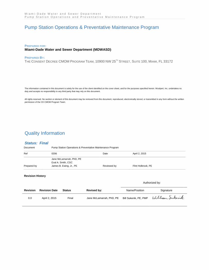
Pump Station Operations & Preventative Maintenance Program
PREPARED FOR:
Miami-Dade Water and Sewer Department (MDWASD)
PREPARED BY:
THE CONSENT DECREE CMOM PROGRAM TEAM, 10900 NW 25TH
STREET, SUITE 100, MIAMI, FL 33172
The information contained in this document is solely for the use of the client identified on the cover sheet, and for the purposes specified herein. Woolpert, Inc. undertakes no
duty and accepts no responsibility to any third party that may rely on this document.
All rights reserved. No section or element of this document may be removed from this document, reproduced, electronically stored, or transmitted in any form without the written
permission of the CD CMOM Program Team.
Quality Information
Status: Final Document Pump Station Operations & Preventative Maintenance Program
Ref 0206 Date April 2, 2015
Prepared by
Jane McLamarrah, PhD, PE
Eval A. Smith, CGC
James B. Ewing, Jr., PE Reviewed by Flint Holbrook, PE
Revision History
Authorized by:
Revision Revision Date Status Revised by: Name/Position Signature
0.0 April 2, 2015 Final Jane McLamarrah, PhD, PE Bill Sukenik, PE, PMP

M i a m i - D a d e W a t e r a n d S e w e r D e p a r t m e n t P a g e | iv P u m p S t a t i o n O p e r a t i o n s a n d P r e v e n t a t i v e M a i n t e n a n c e P r o g r a m
D:\Miami Dade\2015 CMOM\PS Task\PSOPMP\MDWASD CMOM - Task 2.5 PSOPMP final issue 2015 0402.docx
THIS PAGE LEFT INTENTIONALLY BLANK
M i a m i - D a d e W a t e r a n d S e w e r D e p a r t m e n t P u m p S t a t i o n O p e r a t i o n s a n d P r e v e n t a t i v e M a i n t e n a n c e P r o g r a m P a g e | v
D:\Miami Dade\2015 CMOM\PS Task\PSOPMP\MDWASD CMOM - Task 2.5 PSOPMP final issue 2015 0402.docx
Table of Contents List of Tables ...........................................................................................................................vii
List of Figures .........................................................................................................................vii
Acronyms / Glossary ................................................................................................ 00-1 00.
Acronyms / Abbreviations .............................................................................. 00-1 00.01 Glossary ........................................................................................................ 00-1 00.02
Introduction............................................................................................................... 01-1 01.
Summary of the Pump Station System ........................................................... 01-1 01.01
01.01.1 Pump Station Service Areas ......................................................... 01-2
01.01.2 Pump Station Flow Schematics .................................................... 01-2
Regulatory Drivers ......................................................................................... 01-4 01.02 Miami-Dade County Organization .................................................................. 01-6 01.03
01.03.1 Water and Sewer Department Organization ................................. 01-6
01.03.2 Pump Station Division Organization .............................................. 01-8
PSOPMP Overview ...................................................................................... 01-10 01.04 PSOPMP Document Organization ............................................................... 01-10 01.05
PSOPMP Purpose and Goals ................................................................................... 02-1 02.
PSOPMP Purpose ......................................................................................... 02-1 02.01 PSOPMP Goals ............................................................................................. 02-1 02.02
Phased PSOPMP Plan Development ....................................................................... 03-1 03.
PSOPMP Plan Review and Revision ............................................................. 03-1 03.01 Planned Supportive Actions ........................................................................... 03-2 03.02
03.02.1 Phased Implementation Actions.................................................... 03-2
03.02.2 Implementation Schedule ............................................................. 03-3
PSOPMP Performance Measures ............................................................................ 04-1 04.
Purpose of Performance Measures ................................................................ 04-1 04.01 Established Performance Measures............................................................... 04-1 04.02 Performance Metric Reviews and Revisions .................................................. 04-2 04.03
Pump Station Maintenance ...................................................................................... 05-1 05.
Means and Modes of Communication ............................................................ 05-1 05.01
05.01.1 Personnel Communications .......................................................... 05-1
05.01.2 Equipment Communications ......................................................... 05-2
Pump Station Technical Specifications .......................................................... 05-4 05.02 Updating Pump Station Specifications ........................................................... 05-7 05.03 Pump Station Monitoring Systems ............................................................... 05-11 05.04
Pump Station Emergency Maintenance ................................................................ 06-13 06.
Sewer Overflow Response Plan Overview ................................................... 06-14 06.01 Problem Identification .................................................................................. 06-14 06.02 Emergency Operation Equipment and Capabilities ...................................... 06-14 06.03
06.03.1 Backup Power ............................................................................ 06-15
06.03.2 Portable Bypass Pumping........................................................... 06-15
Emergency Maintenance Procedures .......................................................... 06-16 06.04
M i a m i - D a d e W a t e r a n d S e w e r D e p a r t m e n t P a g e | vi P u m p S t a t i o n O p e r a t i o n s a n d P r e v e n t a t i v e M a i n t e n a n c e P r o g r a m
D:\Miami Dade\2015 CMOM\PS Task\PSOPMP\MDWASD CMOM - Task 2.5 PSOPMP final issue 2015 0402.docx
Post-Event Analysis ..................................................................................... 06-18 06.05
Pump Station Preventative and Predictive Maintenance ....................................... 07-1 07.
Preventative Maintenance Activities and Responsibilities .............................. 07-3 07.01
07.01.1 Staffing Resources and Capabilities ............................................. 07-3
07.01.2 Service and Calibration ................................................................. 07-3
07.01.3 Predictive Maintenance ................................................................ 07-6
Preventative and Predictive Maintenance Schedules ................................... 07-10 07.02
07.02.1 Pump Station RM/PM Schedules ................................................ 07-11
07.02.2 Monitoring Systems RM/PM Schedules ...................................... 07-12
Monthly Work Order Status Reports............................................................. 07-14 07.03
Inventory Management System ............................................................................... 08-1 08.
Spare Part Locations ..................................................................................... 08-1 08.01 Critical Parts and Equipment Locations .......................................................... 08-2 08.02 Inventory Management .................................................................................. 08-2 08.03 Procedures for Updating List .......................................................................... 08-3 08.04
Staffing and Funding Plan ....................................................................................... 09-1 09.
Staff and Skills Needs .................................................................................... 09-1 09.01 Training .......................................................................................................... 09-6 09.02 Funding Needs .............................................................................................. 09-7 09.03
Climate Change Impacts .......................................................................................... 10-1 10.
Pump Station Vulnerability to Climate Change ............................................... 10-1 10.01
Appendices ............................................................................................................... 11-5 11.
Appendices APPENDIX A Pump Station Route Flow Schematic by Treatment Plant Service Area APPENDIX B EAMS Pump Station Database APPENDIX C Routine and Preventative Maintenance Task Lists for the Trades APPENDIX D Pump Station Meter Inventory APPENDIX E SCADA Maintenance Task List APPENDIX F Work Order Status Report EAMS Screen Shot Examples APPENDIX G Critical Spare Parts and Equipment List APPENDIX H Pump Station Division Job List APPENDIX I Anticipated Budget Needs
M i a m i - D a d e W a t e r a n d S e w e r D e p a r t m e n t P u m p S t a t i o n O p e r a t i o n s a n d P r e v e n t a t i v e M a i n t e n a n c e P r o g r a m P a g e | vii
D:\Miami Dade\2015 CMOM\PS Task\PSOPMP\MDWASD CMOM - Task 2.5 PSOPMP final issue 2015 0402.docx
List of Tables
Table 00.1 Abbreviations Used in the PSOPMP .................................................................. 00-1
Table 01.1 Location of CD Requirements in PSOPMP ...................................................... 01-11
Table 03.1 Proposed PSOPMP Phased Implementation Activities ...................................... 03-4
Table 04.1 Key PSOPMP Performance Indicators .............................................................. 04-2
Table 05.1 Master Pump Station Listing .............................................................................. 05-4
Table 05.2 Regional Pump Station Listing ........................................................................... 05-5
Table 05.3 Booster Pump Station Listing ............................................................................ 05-6
Table 09.1 PSD Pump Stations Compared to Fiscal Year PSD Budgeted / Contracted Staff Positions ................................................................................ 09-1
Table 09.2 Recommended Staffing Additions Within the PSD ............................................. 09-3
Table 09.3 Anticipated PSOPMP Phased Implementation Funding Required ..................... 09-8
Table 10.1 Saffir-Simpson Hurricane Wind Scale ................................................................ 10-2
Table 10.2 Recommended Planning Horizon Based On Asset Life ..................................... 10-4
List of Figures
Figure 01.1 MDWASD Pump Station Maintenance Service Areas ...................................... 01-3
Figure 01.2 MDWASD Organization Chart .......................................................................... 01-7
Figure 01.3 Pump Station Division Organization Chart ........................................................ 01-8
Figure 06.1 Wastewater Pump Station Bypass Schematic ................................................ 06-16
Figure 07.1 Example Thermal Imaging Predictive Maintenance .......................................... 07-8
Figure 07.2 Example Megger Test Equipment .................................................................... 07-9
Figure 07.3 Preventative Maintenance (PM) / Routine Maintenance (RM) Flow Chart ...... 07-11
Figure 10.1 Pump Station Generic Service Life Schematic ................................................. 10-3

M i a m i - D a d e W a t e r a n d S e w e r D e p a r t m e n t P a g e | viii P u m p S t a t i o n O p e r a t i o n s a n d P r e v e n t a t i v e M a i n t e n a n c e P r o g r a m
D:\Miami Dade\2015 CMOM\PS Task\PSOPMP\MDWASD CMOM - Task 2.5 PSOPMP final issue 2015 0402.docx
THIS PAGE LEFT INTENTIONALLY BLANK
M i a m i - D a d e W a t e r a n d S e w e r D e p a r t m e n t P u m p S t a t i o n O p e r a t i o n s a n d P r e v e n t a t i v e M a i n t e n a n c e P r o g r a m P a g e | 00-1
D:\Miami Dade\2015 CMOM\PS Task\PSOPMP\MDWASD CMOM - Task 2.5 PSOPMP final issue 2015 0402.docx
Acronyms / Glossary 00.
Acronyms / Abbreviations 00.01
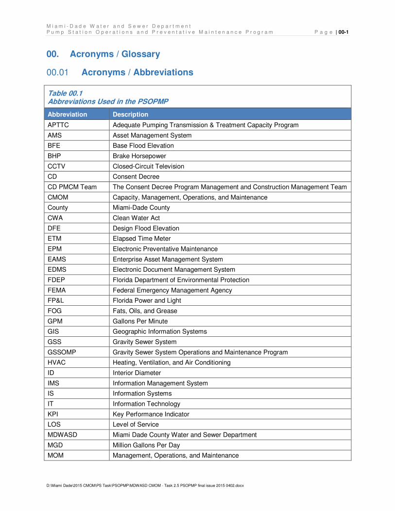
Table 00.1 Abbreviations Used in the PSOPMP
Abbreviation Description
APTTC Adequate Pumping Transmission & Treatment Capacity Program
AMS Asset Management System
BFE Base Flood Elevation
BHP Brake Horsepower
CCTV Closed-Circuit Television
CD Consent Decree
CD PMCM Team The Consent Decree Program Management and Construction Management Team
CMOM Capacity, Management, Operations, and Maintenance
County Miami-Dade County
CWA Clean Water Act
DFE Design Flood Elevation
ETM Elapsed Time Meter
EPM Electronic Preventative Maintenance
EAMS Enterprise Asset Management System
EDMS Electronic Document Management System
FDEP Florida Department of Environmental Protection
FEMA Federal Emergency Management Agency
FP&L Florida Power and Light
FOG Fats, Oils, and Grease
GPM Gallons Per Minute
GIS Geographic Information Systems
GSS Gravity Sewer System
GSSOMP Gravity Sewer System Operations and Maintenance Program
HVAC Heating, Ventilation, and Air Conditioning
ID Interior Diameter
IMS Information Management System
IS Information Systems
IT Information Technology
KPI Key Performance Indicator
LOS Level of Service
MDWASD Miami Dade County Water and Sewer Department
MGD Million Gallons Per Day
MOM Management, Operations, and Maintenance
M i a m i - D a d e W a t e r a n d S e w e r D e p a r t m e n t P a g e | 00-2 P u m p S t a t i o n O p e r a t i o n s a n d P r e v e n t a t i v e M a i n t e n a n c e P r o g r a m
D:\Miami Dade\2015 CMOM\PS Task\PSOPMP\MDWASD CMOM - Task 2.5 PSOPMP final issue 2015 0402.docx
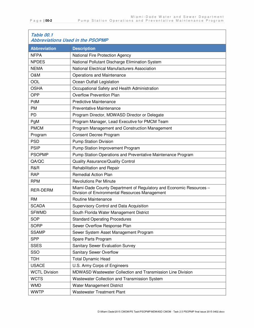
Table 00.1 Abbreviations Used in the PSOPMP
Abbreviation Description
NFPA National Fire Protection Agency
NPDES National Pollutant Discharge Elimination System
NEMA National Electrical Manufacturers Association
O&M Operations and Maintenance
OOL Ocean Outfall Legislation
OSHA Occupational Safety and Health Administration
OPP Overflow Prevention Plan
PdM Predictive Maintenance
PM Preventative Maintenance
PD Program Director, MDWASD Director or Delegate
PgM Program Manager, Lead Executive for PMCM Team
PMCM Program Management and Construction Management
Program Consent Decree Program
PSD Pump Station Division
PSIP Pump Station Improvement Program
PSOPMP Pump Station Operations and Preventative Maintenance Program
QA/QC Quality Assurance/Quality Control
R&R Rehabilitation and Repair
RAP Remedial Action Plan
RPM Revolutions Per Minute
RER-DERM Miami-Dade County Department of Regulatory and Economic Resources – Division of Environmental Resources Management
RM Routine Maintenance
SCADA Supervisory Control and Data Acquisition
SFWMD South Florida Water Management District
SOP Standard Operating Procedures
SORP Sewer Overflow Response Plan
SSAMP Sewer System Asset Management Program
SPP Spare Parts Program
SSES Sanitary Sewer Evaluation Survey
SSO Sanitary Sewer Overflow
TDH Total Dynamic Head
USACE U.S. Army Corps of Engineers
WCTL Division MDWASD Wastewater Collection and Transmission Line Division
WCTS Wastewater Collection and Transmission System
WMD Water Management District
WWTP Wastewater Treatment Plant
M i a m i - D a d e W a t e r a n d S e w e r D e p a r t m e n t P u m p S t a t i o n O p e r a t i o n s a n d P r e v e n t a t i v e M a i n t e n a n c e P r o g r a m P a g e | 00-3
D:\Miami Dade\2015 CMOM\PS Task\PSOPMP\MDWASD CMOM - Task 2.5 PSOPMP final issue 2015 0402.docx
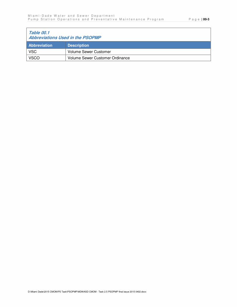
Table 00.1 Abbreviations Used in the PSOPMP
Abbreviation Description
VSC Volume Sewer Customer
VSCO Volume Sewer Customer Ordinance

M i a m i - D a d e W a t e r a n d S e w e r D e p a r t m e n t P a g e | 00-4 P u m p S t a t i o n O p e r a t i o n s a n d P r e v e n t a t i v e M a i n t e n a n c e P r o g r a m
D:\Miami Dade\2015 CMOM\PS Task\PSOPMP\MDWASD CMOM - Task 2.5 PSOPMP final issue 2015 0402.docx
THIS PAGE LEFT INTENTIONALLY BLANK
M i a m i - D a d e W a t e r a n d S e w e r D e p a r t m e n t P u m p S t a t i o n O p e r a t i o n s a n d P r e v e n t a t i v e M a i n t e n a n c e P r o g r a m P a g e | 00-1
D:\Miami Dade\2015 CMOM\PS Task\PSOPMP\MDWASD CMOM - Task 2.5 PSOPMP final issue 2015 0402.docx
Glossary 00.02
Building Backup: A wastewater release or backup into a building or private property that is
caused by blockages, flow conditions, or other malfunctions in Miami-Dade’s wastewater
collection and transmission system (WCTS). A wastewater backup or release that is caused by
blockages, flow conditions, or other malfunctions of a Private Lateral or internal building
plumbing is not a Building Backup.
Capacity, Management, Operations, and Maintenance (CMOM): A program of accepted
industry practices to properly manage, operate, and maintain sanitary wastewater collection,
transmission, and treatment systems, investigate capacity constrained areas of these systems,
and respond to sanitary sewer overflow (SSO) events.
Closed-circuit Television (CCTV): Technology by which Miami-Dade inspection crews and/or
its outside contractors use a video camera to visually inspect the internal condition of pipes and
sub-surface structures.
Consent Decree (CD): The Consent Decree, Case: 1:12-cv-24400-FAM, negotiated between
Miami-Dade County, Florida (Defendant), the Florida Department of Environmental Protection
and the U.S. Environmental Protection Agency (Plaintiffs).
Consent Decree Program Management and Construction Management Team (CD PMCM):
The professional services consulting team competitively selected by the County to support
MDWASD in the implementation of the requirements of the CD.
Environmental Protection Agency (EPA): United States Environmental Protection Agency
and any of its successor departments or agencies.
Fats, Oils, and Grease (FOG) Control Program: “FOG” refers to fats, oils, and grease, which
are generated by residents and businesses processing or serving food and other products. A
FOG Control program aims to prevent FOG accumulation in sewer systems.
M i a m i - D a d e W a t e r a n d S e w e r D e p a r t m e n t P a g e | 00-2 P u m p S t a t i o n O p e r a t i o n s a n d P r e v e n t a t i v e M a i n t e n a n c e P r o g r a m
D:\Miami Dade\2015 CMOM\PS Task\PSOPMP\MDWASD CMOM - Task 2.5 PSOPMP final issue 2015 0402.docx
Force Mains: Any pipe that receives and conveys, under pressure, wastewater from the
discharge side of a pump. A force main is intended to convey wastewater under pressure.
Geographic Information System (GIS): A system consisting of hardware, software, and data
that is designed to capture, store, and analyze geographically-referenced information.
Gravity Sewer Line or Gravity Sewer: Pipes that receive, contain, and convey wastewater not
normally under pressure, but are intended to flow unassisted under the influence of gravity.
Gravity Sewer System Operations and Maintenance Program (GSSOMP): The Consent
Decree stipulated CMOM deliverable that sets forth the protocols and procedures associated
with the operations and maintenance gravity sewer system.
Infiltration: As defined by 40 CFR § 35.2005(b)(20) shall mean water other than wastewater
that enters the WCTS (including sewer service connections and foundation drains) from the
ground through such means as defective pipe, pipe joints, connections, or manholes.
Inflow: As defined by 40 CFR § 35.2005(b)(21) shall mean water other than wastewater that
enters the WCTS (including sewer service connections) from sources such as, but not limited to,
roof leaders, cellar drains, yard drains, area drains, drains from springs and swampy areas,
manhole covers, cross connections between storm sewers and sanitary sewers, catch basins,
cooling towers, storm water, surface runoff, street wash waters, or drainage.
Infiltration and Inflow (I/I): The total quantity of water from inflow, infiltration, and rainfall-
induced infiltration and inflow without distinguishing the source.
Lift Station: A facility in the WCTS comprised of pumps which lift wastewater to a higher
hydraulic elevation, including related electrical, mechanical, and structural systems necessary to
the operation of the lift station (referenced in this document as pump station). As defined in
MDWASD’s 1996 O&M Manual, lift stations discharge to a downstream gravity main.
M i a m i - D a d e W a t e r a n d S e w e r D e p a r t m e n t P u m p S t a t i o n O p e r a t i o n s a n d P r e v e n t a t i v e M a i n t e n a n c e P r o g r a m P a g e | 00-3
D:\Miami Dade\2015 CMOM\PS Task\PSOPMP\MDWASD CMOM - Task 2.5 PSOPMP final issue 2015 0402.docx
Manhole or Junction Box: Part of the gravity sewer system. A structure which provides a
connection point for gravity lines, private service laterals, or force mains, as well as an access
point for maintenance and repair activities.
Master Pump Station: A Master Pump Station is a type A wet well / dry well pump station with
a building housing five or more large pumps (greater than 25 brake horsepower (BHP) each).
Master Pump Stations pump into large force mains that feed directly to a treatment plant.
Miami-Dade: Miami-Dade County, Florida, including all of its departments, agencies,
instrumentalities such as the Water and Sewer Department and the Department of Regulatory
and Economic Resources, and any successors thereto.
NPDES: The National Pollutant Discharge Elimination System (NPDES) authorized under
Section 403 of the Clean Water Act (CWA).
Nominal Average Pump Operating Time (NAPOT): The criteria from the First Partial Consent
Decree and the Second and Final Partial Consent Decree requiring that each pump station
operate at a nominal average pump operating time of less than or equal to 10 hours per day
with exceedances of the criteria requiring a Remedial Action Plan and no building permits
issued for connection to the WCTS upstream of that station.
Private Lateral: The portion of a sanitary sewer conveyance pipe that extends from a single-
family, multifamily, apartment or other dwelling unit, or commercial or industrial structure to
which wastewater service is or has been provided up to the property line of such structure or to
a public sewer in a proper easement.
Prohibited Bypass: The intentional diversion of waste streams from any portion of a treatment
facility which is prohibited pursuant to the terms set forth at 40 CFR § 122.41(m).
Public Document Repository (PDR): The Miami-Dade Water and Sewer Department
(MDWASD) located at 3071 SW 38th Ave and the Miami-Dade Water and Sewer Department’s
website, http://www.miamidade.gov/water.
M i a m i - D a d e W a t e r a n d S e w e r D e p a r t m e n t P a g e | 00-4 P u m p S t a t i o n O p e r a t i o n s a n d P r e v e n t a t i v e M a i n t e n a n c e P r o g r a m
D:\Miami Dade\2015 CMOM\PS Task\PSOPMP\MDWASD CMOM - Task 2.5 PSOPMP final issue 2015 0402.docx
Public Lateral: The portion of a sanitary sewer conveyance pipe that extends from the private
lateral, which typically has a cleanout located at the property line or at the easement line, to the
sewer main.
Pump Station: A facility in the WCTS comprised of pumps which transport wastewater from
one location to another location, and which includes related electrical, mechanical, and
structural systems necessary for the operation of the pump station. As defined in MDWASD’s
1996 O&M Manual, pump stations discharge to a force main, to a booster station, or to a
WWTP.
Pump Station Operations and Preventative Maintenance Program (PSOPMP): The Consent
Decree stipulated CMOM deliverable that sets forth the protocols and procedures associated
with the operations and maintenance of the pump station sewer system.
Sanitary Sewer Overflow (SSO): Any discharge of wastewater to waters of the United States
or the State from Miami-Dade’s WCTC through a point source not permitted in any NPDES
permit, as well as any overflow, spill, or release of wastewater to public or private property from
the WCTS that may or may not have reached waters of the United States or the State, including
building backups. A wastewater overflow, backup, or release that is caused by blockages, flow
conditions, or other malfunctions of a Private Lateral or internal building plumbing is not a SSO.
Sewer Overflow Response Plan (SORP): The SORP provides structured guidance, including
a range of field activities to choose from, for a generalized uniform response to overflows,
backup, or releases.
Supervisory Control and Data Acquisition (SCADA) System: A system of automated
sensory control equipment that monitors the operation of lift stations (or pump stations) within
the wastewater collection and transmission system (WCTS). The SCADA system is designed to
convey alarms when predetermined conditions occur, to monitor pump stations operating
parameters and to remotely operate pumps. Monitoring parameters may include, but are not
limited to, power failures, high wet well levels, pump failures that could potentially cause
M i a m i - D a d e W a t e r a n d S e w e r D e p a r t m e n t P u m p S t a t i o n O p e r a t i o n s a n d P r e v e n t a t i v e M a i n t e n a n c e P r o g r a m P a g e | 00-5
D:\Miami Dade\2015 CMOM\PS Task\PSOPMP\MDWASD CMOM - Task 2.5 PSOPMP final issue 2015 0402.docx
overflows, excessive pump runtimes, or other alarm set points as may be determined by system
operators.
Wastewater System: The Wastewater Collection and Transmission System (WCTS) and the
Wastewater Treatment Plants (WWTPs).
Wastewater Collection and Transmission System (WCTS): The municipal wastewater
collection and transmission system, including all pipes, force mains, gravity sewer lines, pump
stations, manholes, and appurtenances thereto, which are owned or operated by the Miami-
Dade designed to collect and convey municipal sewage (domestic, commercial, and industrial to
Miami-Dade’s WWTPs.
Wastewater Treatment Plant (WWTP): Devices or systems used in the storage, treatment,
recycling, and reclamation of municipal wastewater and include all facilities owned, managed,
operated, and maintained by Miami-Dade, including but not limited to the North District WWTP,
the Central District WWTP, and the South District WWTP, and all components of those plants.

M i a m i - D a d e W a t e r a n d S e w e r D e p a r t m e n t P a g e | 00-6 P u m p S t a t i o n O p e r a t i o n s a n d P r e v e n t a t i v e M a i n t e n a n c e P r o g r a m
D:\Miami Dade\2015 CMOM\PS Task\PSOPMP\MDWASD CMOM - Task 2.5 PSOPMP final issue 2015 0402.docx
THIS PAGE LEFT INTENTIONALLY BLANK
M i a m i - D a d e W a t e r a n d S e w e r D e p a r t m e n t P u m p S t a t i o n O p e r a t i o n s a n d P r e v e n t a t i v e M a i n t e n a n c e P r o g r a m P a g e | 01-1
D:\Miami Dade\2015 CMOM\PS Task\PSOPMP\MDWASD CMOM - Task 2.5 PSOPMP final issue 2015 0402.docx
Introduction 01.
The Miami-Dade Water and Sewer Department (MDWASD) prepared this Pump Station
Operations and Preventative Maintenance Program (PSOPMP) plan in compliance with Section
19(f) of the Consent Decree (CD) between Miami-Dade County (County) and the plaintiffs, the
United States of America, the State of Florida (State), and the Florida Department of
Environmental Protection (FDEP), adjudicated by the United States District Court for the
Southern District of Florida in Case No. 1:12-cv-24400-FAM. The CD requires the County to
develop, submit, finalize, and implement plans for the continued improvement of its wastewater
collection and transmission system (WCTS) and wastewater treatment plants (WWTPs) to
eliminate, reduce, prevent, or otherwise control sanitary sewer overflows (SSOs); to correct
effluent limit violations; and to properly manage, operate, and maintain its WCTS and WWTPs.
Summary of the Pump Station System 01.01
As of February 1, 2015, MDWASD’s pump station system consists of 1,028 MDWASD-owned
pump stations, and an additional 19 pump stations maintained under maintenance agreements
with other agencies and departments. In addition, there are numerous private pump stations
discharging wastewater into MDWASD’s WCTS. The number of stations is subject to change
due to additions and abandonments in a dynamic, urban service area such as Miami-Dade
County.
The Pump Station Division (PSD) is responsible for the operation and maintenance (O&M) of
the MDWASD stations and the stations under maintenance agreements, except for the two
master pump stations, PS 0001 (a.k.a., Fourth Street) and PS 0002 (a.k.a., Ninth Street), that
are WWTP influent pump stations operated and maintained by the Wastewater Treatment and
Maintenance Division. The MDWASD pump station system has different types and sizes of
pump stations ranging from smaller lift stations designed to handle individual flows from
commercial establishments, to master stations that receive flows from a large service area and
which pump directly to the treatment plant. For consistency with the CD, this document will refer
to both types of stations as pump stations.
M i a m i - D a d e W a t e r a n d S e w e r D e p a r t m e n t P a g e | 01-2 P u m p S t a t i o n O p e r a t i o n s a n d P r e v e n t a t i v e M a i n t e n a n c e P r o g r a m
D:\Miami Dade\2015 CMOM\PS Task\PSOPMP\MDWASD CMOM - Task 2.5 PSOPMP final issue 2015 0402.docx
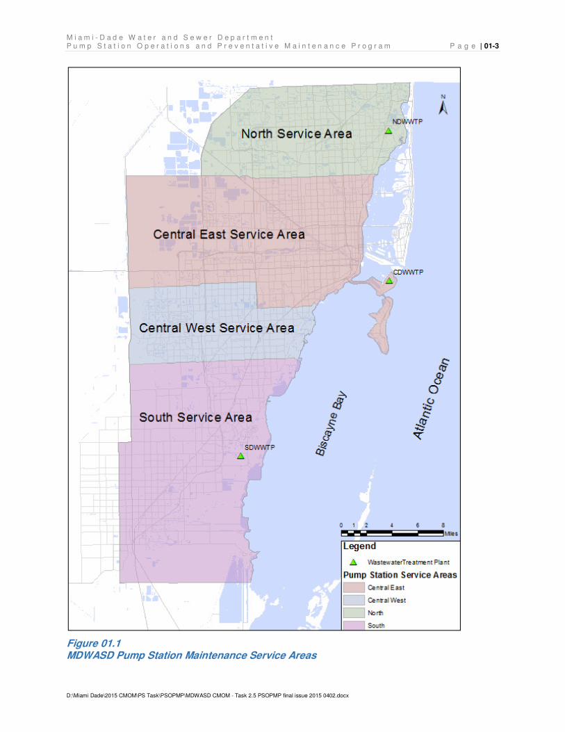
01.01.1 Pump Station Service Areas
The MDWASD treatment plant service area is divided into the North, Central, and South
Districts, each served by separate wastewater treatment facilities. The PSD further divides the
Central District into the Central West and the Central East Service Areas for operational and
maintenance purposes. The WCTS covers approximately 443 square miles of area and, as of
February 1, 2015, included approximately 6,300 miles of pipelines. The MDWASD system also
receives flow from fifteen wholesale municipal customers, known locally as volume sewer
customers.
01.01.2 Pump Station Flow Schematics
The pump station system includes booster stations, regional stations, and master stations
(master stations are regional stations that pump directly into Central District WWTP). The
centrally located Pump Station 187 (33-P1) is utilized to distribute flows between the three
treatment plant service areas. Pump Station 187 has the ability to divert flow from any of the
three districts to another district or to the other two districts. Pump Station 187 also has the
ability to divert flow from any two districts and send their flow to the other district. SCADA
controls are installed to allow PSD personnel to remotely monitor and operate the station.
Diversion of flows requires manual operation of station and transmission valves. Appendix A,
Pump Station Route Flow Schematics, contains flow schematics illustrating the flow path for
each pump station within the various treatment plant service areas. The two Central District
plant influent pump stations, Master Pump Stations 0001 and 0002, which are operated and
maintained by the Wastewater Treatment and Maintenance Division, will be addressed as part
of the WWTP Operations and Maintenance Program, which is a separate CMOM Program
document from this PSOPMP document.
Figure 01.1 on the following page shows the maintenance service area boundaries for Miami-
Dade County.
M i a m i - D a d e W a t e r a n d S e w e r D e p a r t m e n t P u m p S t a t i o n O p e r a t i o n s a n d P r e v e n t a t i v e M a i n t e n a n c e P r o g r a m P a g e | 01-3
D:\Miami Dade\2015 CMOM\PS Task\PSOPMP\MDWASD CMOM - Task 2.5 PSOPMP final issue 2015 0402.docx
Figure 01.1 MDWASD Pump Station Maintenance Service Areas
M i a m i - D a d e W a t e r a n d S e w e r D e p a r t m e n t P a g e | 01-4 P u m p S t a t i o n O p e r a t i o n s a n d P r e v e n t a t i v e M a i n t e n a n c e P r o g r a m
D:\Miami Dade\2015 CMOM\PS Task\PSOPMP\MDWASD CMOM - Task 2.5 PSOPMP final issue 2015 0402.docx
Regulatory Drivers 01.02
Compliance with the requirements of the Clean Water Act (CWA) is the primary regulatory driver
for the PSOPMP. The County negotiated the terms of the CD with EPA and FDEP in response
to violations of the CWA, which consisted of unpermitted discharges of untreated sanitary
sewage into waters of the United States from the WCTS and which are referred to as sanitary
sewer overflows or SSOs.
To support realization of the goal of reducing, preventing, or otherwise controlling SSOs and
prohibited discharges to waters of the United States, the CD, Section 18, requires MDWASD to
continue programs initiated under previous CDs, and Section 19 stipulates the development of
CMOM1 programs across all areas of the wastewater, collection, transmission, and treatment
systems, including: pump stations, force mains, gravity sewers, and wastewater treatment
plants. CD Section 18 “existing” CMOM programs and Section 19 “new” CMOM programs are
listed below. The CD Programs listed in bold italics have direct impact on elements and
requirements of the PSOPMP.
1. 18(a) Adequate Pumping, Transmission, and Treatment Capacity (APTTC)
Program;
2. 18(b) Pump Station Remote Monitoring (PSRM) Program;
3. 18(c) WCTS Model;
4. 18(d) Spare Parts Program (SPP);
5. 18(e) Volume Sewer Customer Ordinance (VSCO) Program;
6. 19(a) Fats, Oils, and Grease (FOG) Control Program;
7. 19(b) Sewer Overflow Response Plan (SORP);
8. 19(c) Information Management System (IMS) Program;
9. 19(d) Sewer System Asset Management Program (SSAMP);
10. 19(e) Gravity Sewer System Operations and Maintenance Program (GSSOMP);
1 The MDWASD wastewater system has not experienced a capacity related SSO since 2002, and
accordingly, the CD focuses on Management, Operations, and Maintenance, or MOM, related programs, but uses the familiar acronym of CMOM throughout the document.
M i a m i - D a d e W a t e r a n d S e w e r D e p a r t m e n t P u m p S t a t i o n O p e r a t i o n s a n d P r e v e n t a t i v e M a i n t e n a n c e P r o g r a m P a g e | 01-5
D:\Miami Dade\2015 CMOM\PS Task\PSOPMP\MDWASD CMOM - Task 2.5 PSOPMP final issue 2015 0402.docx
11. 19(f) Pump Station Operations and Preventative Maintenance Program (PSOPMP);
12. 19(g) Force Main Operations, Preventative Maintenance, and Assessment /
Rehabilitation Program;
13. 19(h) WWTP Operations and Maintenance Program;
14. 19(i) Specific Capital Improvements Projects; and
15. 19(j) Financial Analysis Program.
The sub-paragraphs of 19(f) require specific actions to develop a preventative CMOM program
plan for the pump station system. The PSOPMP must include the following:
• Identification of the means and modes of communication between pump stations, field
crews, and supervising staff;
• Technical specifications of each pump station within the WCTS;
• Description of each pump station monitoring system;
• Written preventative operation and maintenance (O&M) schedules and procedures;
• Written standard emergency / reactive O&M procedures;
• An inventory management system, including critical equipment and critical spare parts;
• Reports listing equipment problems and the status of work orders generated during the
prior month; and
• A staffing and funding plan with structure, skills, numbers, and funding to allow
completion of the O&M activities required by the PSOPMP.
In addition to the specific requirements of Section 19, the CD references specific guidance tools
that support the incorporation of industry CMOM “best-practices” in municipal wastewater utility
operations. Industry CMOM best-practices are those core WCTS management attributes
commonly found in highly performing utilities and often include adoption of asset and life-cycle-
cost management concepts through implementation of preventative and predictive management
policies and procedures. Reductions in emergency maintenance and repair activities leading to
reductions in SSOs demonstrate the effectiveness of these best-practices. The CD requires
concurrent development and implementation of the fifteen separate management programs
M i a m i - D a d e W a t e r a n d S e w e r D e p a r t m e n t P a g e | 01-6 P u m p S t a t i o n O p e r a t i o n s a n d P r e v e n t a t i v e M a i n t e n a n c e P r o g r a m
D:\Miami Dade\2015 CMOM\PS Task\PSOPMP\MDWASD CMOM - Task 2.5 PSOPMP final issue 2015 0402.docx
listed above. The programs’ inherent interdependencies require an interdisciplinary and
integrated approach to wastewater system management, operations, and management.
Miami-Dade County Organization 01.03
The County operates under Home-Rule Authority granted by the Florida State Constitution. The
unincorporated areas of Miami-Dade County are governed by the 13 member Board of County
Commissioners (Commission). The County government provides major metropolitan services
countywide and city-type services for residents of the unincorporated areas. Miami-Dade
County has a Mayor who oversees the day-to-day operations of the County. The County is
organized into 25 Departments, each led by a Mayor-appointed Director.
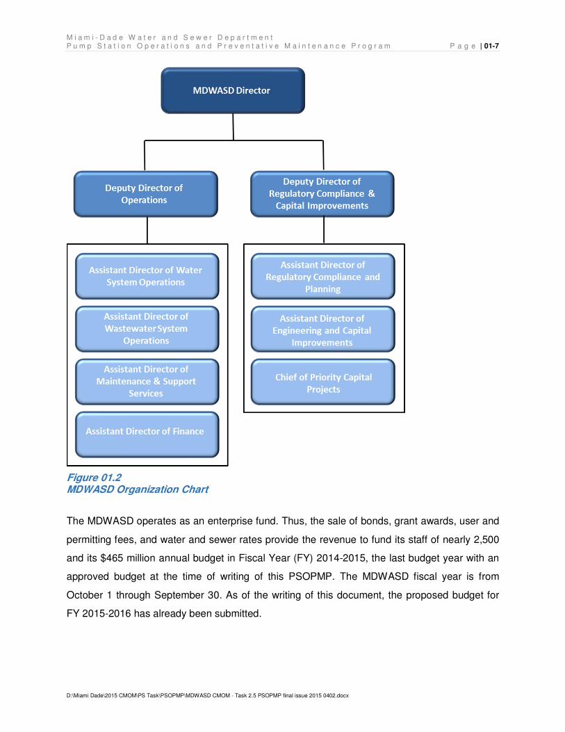
01.03.1 Water and Sewer Department Organization
As shown in Figure 01.2, two Deputy Directors manage the MDWASD under the authority of the
Director: the Deputy Director of Operations and the Deputy Director of Regulatory Compliance
and Capital Improvements. There are four Assistant Directors under the Deputy Director of
Operations, and two Assistant Directors and a Chief of Priority Capital Projects under the
Deputy of Regulatory Compliance and Capital Improvements. As discussed in Subsection
01.03.2 below, the pump stations are under the Assistant Director for Wastewater System
Operations.
M i a m i - D a d e W a t e r a n d S e w e r D e p a r t m e n t P u m p S t a t i o n O p e r a t i o n s a n d P r e v e n t a t i v e M a i n t e n a n c e P r o g r a m P a g e | 01-7
D:\Miami Dade\2015 CMOM\PS Task\PSOPMP\MDWASD CMOM - Task 2.5 PSOPMP final issue 2015 0402.docx
Figure 01.2 MDWASD Organization Chart
The MDWASD operates as an enterprise fund. Thus, the sale of bonds, grant awards, user and
permitting fees, and water and sewer rates provide the revenue to fund its staff of nearly 2,500
and its $465 million annual budget in Fiscal Year (FY) 2014-2015, the last budget year with an
approved budget at the time of writing of this PSOPMP. The MDWASD fiscal year is from
October 1 through September 30. As of the writing of this document, the proposed budget for
FY 2015-2016 has already been submitted.
M i a m i - D a d e W a t e r a n d S e w e r D e p a r t m e n t P a g e | 01-8 P u m p S t a t i o n O p e r a t i o n s a n d P r e v e n t a t i v e M a i n t e n a n c e P r o g r a m
D:\Miami Dade\2015 CMOM\PS Task\PSOPMP\MDWASD CMOM - Task 2.5 PSOPMP final issue 2015 0402.docx
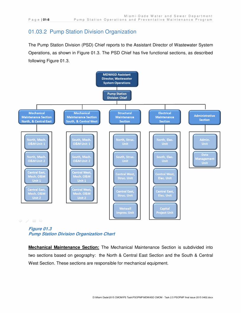
01.03.2 Pump Station Division Organization
The Pump Station Division (PSD) Chief reports to the Assistant Director of Wastewater System
Operations, as shown in Figure 01.3. The PSD Chief has five functional sections, as described
following Figure 01.3.
Figure 01.3 Pump Station Division Organization Chart
Mechanical Maintenance Section: The Mechanical Maintenance Section is subdivided into
two sections based on geography: the North & Central East Section and the South & Central
West Section. These sections are responsible for mechanical equipment.
M i a m i - D a d e W a t e r a n d S e w e r D e p a r t m e n t P u m p S t a t i o n O p e r a t i o n s a n d P r e v e n t a t i v e M a i n t e n a n c e P r o g r a m P a g e | 01-9
D:\Miami Dade\2015 CMOM\PS Task\PSOPMP\MDWASD CMOM - Task 2.5 PSOPMP final issue 2015 0402.docx
Structural Maintenance Section: The Structural Maintenance Section is responsible for the
pump station structures, including buildings, foundations, wet wells, gratings, grounds, etc.
Electrical Maintenance Section: The Electrical Maintenance Section is responsible for
electrical and controls equipment.
Administrative Section: The Administrative Section provides administrative and accounting
support to the other sections and directly to the Division staff.
In addition to the four Sections under the PSD Chief, the PSD obtains assistance from other
groups within MDWASD. The key functional assistance areas are listed, and briefly described,
below. More detailed descriptions are included in subsequent sections of this plan document as
appropriate.
• Wastewater Collection and Transmission Line Division, which is responsible for the
gravity sewer system and the force mains. This group will respond to pump station-
related spills when the spill occurs at a manhole upstream of the pump station or in a
force main downstream of the pump station.
• Emergency Communications Center, which is responsible for receiving “problem calls”
and monitoring Supervisory Control and Data Acquisition System (SCADA) alarms for
the pump stations.
• SCADA Section, which is responsible for implementation and maintenance of the
supervisory control and data acquisition system, network, and infrastructure for all
MDWASD’s pump stations and treatment facilities. Responsibility includes
instrumentation and electronic equipment maintenance for the Pump Station Division.
• Meter Installation and Maintenance Section, which is responsible for meter installation
and maintenance, including the pump station meters as well as the various volume
sewer customer meters and other MDWASD system meters.
• General Maintenance Division, which is responsible for the grounds, fleet, and heating,
ventilation, and air conditioning (HVAC) maintenance.
M i a m i - D a d e W a t e r a n d S e w e r D e p a r t m e n t P a g e | 01-10 P u m p S t a t i o n O p e r a t i o n s a n d P r e v e n t a t i v e M a i n t e n a n c e P r o g r a m
D:\Miami Dade\2015 CMOM\PS Task\PSOPMP\MDWASD CMOM - Task 2.5 PSOPMP final issue 2015 0402.docx
• Stores and Procurement Division, which is responsible for parts inventory, storage, and
purchasing.
PSOPMP Overview 01.04
The considerations necessary for the development of PSOPMP include the regulatory drivers
listed in the previous sub-sections, industry “best-practices” in pump station system O&M, the
other existing and new CMOM Programs, and the local business needs of MDWASD. The
designed interdependencies between regulatory requirements and the other CMOM Programs
necessitate a phased implementation and adoption of a continuous improvement process. The
resultant PSOPMP, the phased implementation, and the continuous improvement processes
are detailed in subsequent sections of this document.
Industry best-practices used by MDWASD and the PSD include that of various professional
organizations, CMOM publications, and national standard organizations for mechanical,
electrical, and structural codes. Examples of such guidance documents used to develop the
PSOPMP include, but are not limited to, Occupational, Safety and Health Administration
(OSHA), Core Attributes of Effectively Managed Wastewater Collection Systems, Effective
Utility Management: A Primer for Water and Wastewater Utilities, Guide for Evaluating Capacity,
Management, Operation, and Maintenance (CMOM) Programs at Sanitary Sewer Collection
Systems, Optimization of Collection System Maintenance Frequencies and System
Performance, Optimizing Operation, Maintenance, and Rehabilitation of Sanitary Sewer
Collection Systems, Protocols for identifying Sanitary Sewer Overflows, Sanitary Sewer
Overflow Solutions, National Electric Code, National Electrical Manufacturers Association
(NEMA) standards and specifications, Electrical Safety Orders, General Industry Safety Orders,
Uniform Building Code, and National Fire Protection Code.
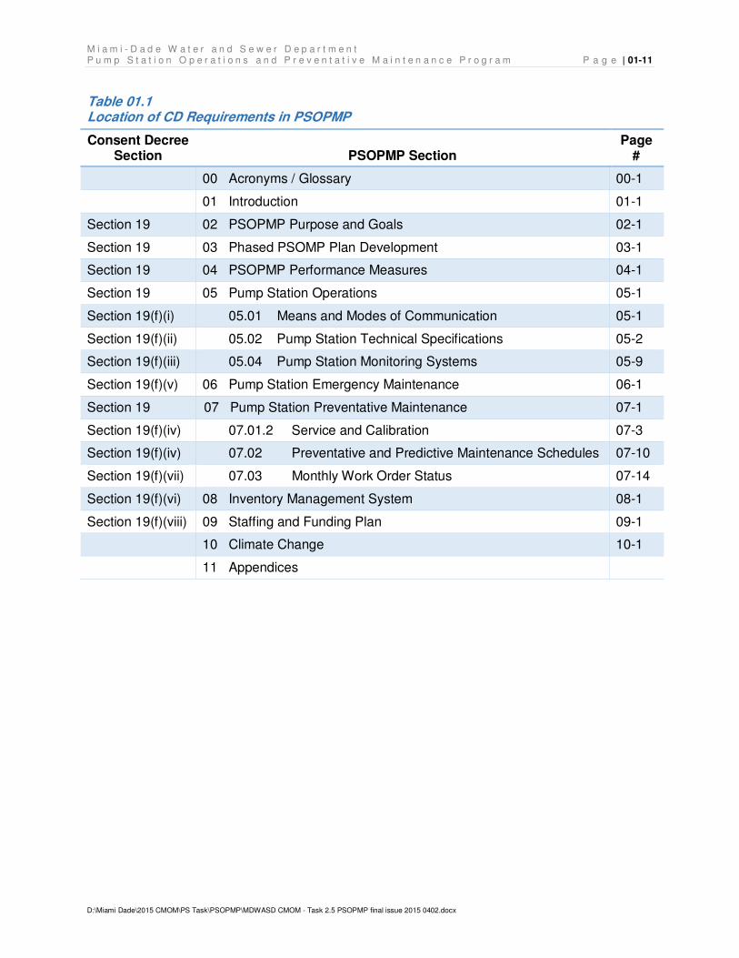
PSOPMP Document Organization 01.05
This PSOPMP plan document is organized to meet both the requirements of the CD as well as
the business needs of the PSD. The PSOPMP plan organization is listed in Table 01.1. Where
applicable, the corresponding CD section reference is listed adjacent to the section or
subsection name and the associated document page number.
M i a m i - D a d e W a t e r a n d S e w e r D e p a r t m e n t P u m p S t a t i o n O p e r a t i o n s a n d P r e v e n t a t i v e M a i n t e n a n c e P r o g r a m P a g e | 01-11
D:\Miami Dade\2015 CMOM\PS Task\PSOPMP\MDWASD CMOM - Task 2.5 PSOPMP final issue 2015 0402.docx
Table 01.1 Location of CD Requirements in PSOPMP
Consent Decree Section PSOPMP Section
Page #
00 Acronyms / Glossary 00-1
01 Introduction 01-1
Section 19 02 PSOPMP Purpose and Goals 02-1
Section 19 03 Phased PSOMP Plan Development 03-1
Section 19 04 PSOPMP Performance Measures 04-1
Section 19 05 Pump Station Operations 05-1
Section 19(f)(i) 05.01 Means and Modes of Communication 05-1
Section 19(f)(ii) 05.02 Pump Station Technical Specifications 05-2
Section 19(f)(iii) 05.04 Pump Station Monitoring Systems 05-9
Section 19(f)(v) 06 Pump Station Emergency Maintenance 06-1
Section 19 07 Pump Station Preventative Maintenance 07-1
Section 19(f)(iv) 07.01.2 Service and Calibration 07-3
Section 19(f)(iv) 07.02 Preventative and Predictive Maintenance Schedules 07-10
Section 19(f)(vii) 07.03 Monthly Work Order Status 07-14
Section 19(f)(vi) 08 Inventory Management System 08-1
Section 19(f)(viii) 09 Staffing and Funding Plan 09-1
10 Climate Change 10-1
11 Appendices

M i a m i - D a d e W a t e r a n d S e w e r D e p a r t m e n t P a g e | 01-12 P u m p S t a t i o n O p e r a t i o n s a n d P r e v e n t a t i v e M a i n t e n a n c e P r o g r a m
D:\Miami Dade\2015 CMOM\PS Task\PSOPMP\MDWASD CMOM - Task 2.5 PSOPMP final issue 2015 0402.docx
THIS PAGE LEFT INTENTIONALLY BLANK
M i a m i - D a d e W a t e r a n d S e w e r D e p a r t m e n t P u m p S t a t i o n O p e r a t i o n s a n d P r e v e n t a t i v e M a i n t e n a n c e P r o g r a m P a g e | 02-1
D:\Miami Dade\2015 CMOM\PS Task\PSOPMP\MDWASD CMOM - Task 2.5 PSOPMP final issue 2015 0402.docx
PSOPMP Purpose and Goals 02.
In accordance with the CD requirement to establish a written, defined purpose and written,
defined goals, Section 02.01 provides the PSOPMP purpose and Section 02.02 provides the
PSOPMP goals.
PSOPMP Purpose 02.01
The purpose of the PSOPMP is to establish and document processes and procedures to
operate and maintain MDWASD’s pump stations, and the pump stations under maintenance
agreements with MDWASD, in a manner that ensures the pump stations:
• Operate as designed by trained, well-qualified staff,
• Provide uninterrupted service to customers,
• Extend the useful life of pump station assets, and
• Optimize operational and capital replacement expenditures to maintain affordable
customer rates.
PSOPMP Goals 02.02
The PSOPMP goals are to:
• Operate and maintain the pump stations with minimal service interruptions,
• Perform preventative and predictive maintenance in a manner that minimizes the
potential for structural, mechanical, electrical, instrumentation, or hydraulic failures that
could result in SSO events,
• Ensure pump station-related malfunctions or failures are corrected in a timely, efficient,
and effective manner, and
• Maximize the level of customer service, regulatory compliance, and the effective use of
resources for pump station-related activities.
This document contains the initial phase of the PSOPMP plan and a schedule of specific
recommendations intended to transition this program into subsequent phases.

M i a m i - D a d e W a t e r a n d S e w e r D e p a r t m e n t P a g e | 02-2 P u m p S t a t i o n O p e r a t i o n s a n d P r e v e n t a t i v e M a i n t e n a n c e P r o g r a m
D:\Miami Dade\2015 CMOM\PS Task\PSOPMP\MDWASD CMOM - Task 2.5 PSOPMP final issue 2015 0402.docx
THIS PAGE LEFT INTENTIONALLY BLANK
M i a m i - D a d e W a t e r a n d S e w e r D e p a r t m e n t P u m p S t a t i o n O p e r a t i o n s a n d P r e v e n t a t i v e M a i n t e n a n c e P r o g r a m P a g e | 03-1
D:\Miami Dade\2015 CMOM\PS Task\PSOPMP\MDWASD CMOM - Task 2.5 PSOPMP final issue 2015 0402.docx
Phased PSOPMP Plan Development 03.
PSOPMP development and implementation will be phased to ensure cohesiveness and proper
integration of the PSOPMP with other CD-required CMOM Programs currently under
development. The PSOPMP relies upon the management and implementation efficiency gained
through incorporation of specific knowledge area policies, procedures, activities, technologies,
and tools inherent to other CMOM Programs. Portions of the PSOPMP that are consistent with
existing pump station O&M activities will be implemented immediately. Portions of the
recommended PSOPMP activities that will require additional field investigations to fully populate
databases, such as the Technical Specifications database, will be part of the phased
implementation process. The phased implementation is summarized in Section 03.02, Planned
Support Activities, below, as well as noted in the applicable detailed section of this plan
document devoted to that particular implementation activity.
PSOPMP Plan Review and Revision 03.01
In accordance with the CMOM philosophy of continuous improvement, the PSD developed
internal performance measures as described in Section 04, PSOPMP Performance Measures,
to evaluate PSOPMP progress toward established goals. Monthly performance measure reports
will be generated and evaluated on a semi-annual and annual basis.
The defined performance measures may be modified to better suit the business needs of the
County. Material changes to the PSOPMP will be submitted to the EPA/FDEP for review and
approval and documented in the Annual Report submitted to EPA/FDEP as part of CD reporting
compliance.
During the annual review, the monthly reports and the semi-annual evaluation will be reviewed,
and lessons learned will be noted to enable MDWASD to continuously improve the PSOPMP
and other affected programs. The annual review will also include a review of the effect of other
CMOM Programs, changing conditions, revisions to regulatory requirements, and other factors
that may impact the pump station system. As the PSOPMP matures, less frequent evaluations
may be recommended. The results will continue to be documented in the Annual Report to
EPA/FDEP as part of CD reporting compliance.
M i a m i - D a d e W a t e r a n d S e w e r D e p a r t m e n t P a g e | 03-2 P u m p S t a t i o n O p e r a t i o n s a n d P r e v e n t a t i v e M a i n t e n a n c e P r o g r a m
D:\Miami Dade\2015 CMOM\PS Task\PSOPMP\MDWASD CMOM - Task 2.5 PSOPMP final issue 2015 0402.docx
Planned Supportive Actions 03.02
As noted above, the proposed PSOPMP depends on other yet-to-be-developed and
implemented new CMOM Programs. The disparity between the required EPA/FDEP submittal
dates for these CMOM Programs not only demonstrates a need for a phased implementation
approach, but the need to consolidate new CMOM Program implementation schedules. Upon
EPA/FDEP approval of other CMOM Program plan documents, MDWASD will submit a
proposed consolidated implementation plan and schedule to include CMOM Programs. This will
facilitate the task of tracking implementation for CMOM programs, individual CMOM elements,
required resources, and schedules.
Implementation of the PSOPMP is contingent upon distinct CD controlled and non-CD
controlled predecessors. These include, but are not limited to:
• Submittal, and subsequent EPA/FDEP approval, of the IMS, the SORP, and the Sewer
System Asset Management CMOM Programs;
• Completion of, or updates to, existing CMOM Programs, i.e., Adequate Pumping,
Transmission and Treatment Capacity, Pump Station Remote Monitoring (SCADA), the
WCTS Model, Spare Parts, and the Volume Sewer Customer Ordinance Programs;
• Completion of the Miami-Dade GIS Updates and addition of accurate manhole rim and
invert elevations upstream of pump stations;
• Implementation of the IMS and the SSAMP CMOM Programs; and
• Allocation and acquisition of PSOPMP staffing and funding resources to augment the
PSD’s existing resources to expand its preventative and predictive maintenance
activities.
03.02.1 Phased Implementation Actions
The proposed staffing and associated funding for the phased implementation of the PSOPMP is
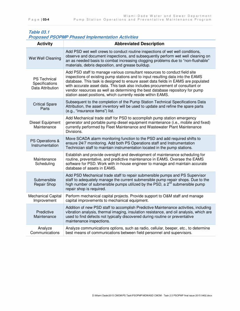
detailed in Section 09, Staffing and Funding Plan, Table 03.1 on the following page summarizes
the key implementation activities. Implementation of these activities will require additional staff
and equipment as detailed in Table 09.2 in Section 09 as well as the consultant/vendor
resources.
M i a m i - D a d e W a t e r a n d S e w e r D e p a r t m e n t P u m p S t a t i o n O p e r a t i o n s a n d P r e v e n t a t i v e M a i n t e n a n c e P r o g r a m P a g e | 03-3
D:\Miami Dade\2015 CMOM\PS Task\PSOPMP\MDWASD CMOM - Task 2.5 PSOPMP final issue 2015 0402.docx
03.02.2 Implementation Schedule
The PSOPMP will be implemented in phases. Portions of the PSOPMP will be implemented
immediately. The immediate implementation items include the routine and preventative
maintenance activities that are currently being performed. Upon EPA/FDEP approval of this
PSOPMP and the other CMOM Program documents for which PSOPMP dependencies exist,
the activities listed in Table 03.1 will be implemented.
A consolidated implementation schedule will be developed as part of the Information
Management System (IMS) Program. The IMS Program is required to be submitted by
December 6, 2015.
M i a m i - D a d e W a t e r a n d S e w e r D e p a r t m e n t P a g e | 03-4 P u m p S t a t i o n O p e r a t i o n s a n d P r e v e n t a t i v e M a i n t e n a n c e P r o g r a m
D:\Miami Dade\2015 CMOM\PS Task\PSOPMP\MDWASD CMOM - Task 2.5 PSOPMP final issue 2015 0402.docx
Table 03.1 Proposed PSOPMP Phased Implementation Activities
Activity Abbreviated Description
Wet Well Cleaning
Add PSD wet well crews to conduct routine inspections of wet well conditions, observe and document inspections, and subsequently perform wet well cleaning on an as needed basis to combat increasing clogging problems due to “non-flushable” materials, debris deposition, and grease buildup.
PS Technical Specifications
Data Attribution
Add PSD staff to manage various consultant resources to conduct field site inspections of existing pump stations and to input resulting data into the EAMS database. This task is designed to ensure asset data fields in EAMS are populated with accurate asset data. This task also includes procurement of consultant or vendor resources as well as determining the best database repository for pump station asset positions, which currently reside within EAMS.
Critical Spare Parts
Subsequent to the completion of the Pump Station Technical Specifications Data Attribution, the asset inventory will be used to update and refine the spare parts (e.g., “insurance items”) list.
Diesel Equipment Maintenance
Add Mechanical trade staff for PSD to accomplish pump station emergency generator and portable pump diesel equipment maintenance (i.e., mobile and fixed) currently performed by Fleet Maintenance and Wastewater Plant Maintenance Divisions.
PS Operations & Instrumentation
Move SCADA alarm monitoring function to the PSD and add required shifts to ensure 24/7 monitoring. Add both PS Operations staff and Instrumentation Technician staff to maintain instrumentation located in the pump stations.
Maintenance Scheduling
Establish and provide oversight and development of maintenance scheduling for routine, preventative, and predictive maintenance in EAMS. Oversee the EAMS software for PSD. Work with in-house engineer to manage and maintain accurate database of assets in EAMS.
Submersible Repair Shop
Add PSD Mechanical trade staff to repair submersible pumps and PS Supervisor staff to adequately manage the current submersible pump repair shops. Due to the high number of submersible pumps utilized by the PSD, a 2
nd submersible pump
repair shop is required.
Mechanical Capital Improvement
Perform mechanical capital projects. Provide support to O&M staff and manage capital improvements to mechanical equipment.
Predictive Maintenance
Addition of new PSD staff to accomplish Predictive Maintenance activities, including vibration analysis, thermal imaging, insulation resistance, and oil analysis, which are used to find defects not typically discovered during routine or preventative maintenance inspections.
Analyze Communications
Analyze communications options, such as radio, cellular, beeper, etc., to determine best means of communications between field personnel and supervisors.
M i a m i - D a d e W a t e r a n d S e w e r D e p a r t m e n t P u m p S t a t i o n O p e r a t i o n s a n d P r e v e n t a t i v e M a i n t e n a n c e P r o g r a m P a g e | 04-1
D:\Miami Dade\2015 CMOM\PS Task\PSOPMP\MDWASD CMOM - Task 2.5 PSOPMP final issue 2015 0402.docx
PSOPMP Performance Measures 04.
In accordance with the CD requirement that MDWASD establish performance measures and
develop written procedures for periodic review, Section 04.01 establishes the purpose for the
performance measure program; Section 04.02 lists the PSOPMP performance measures; and
Section 04.03 describes the on-going evaluation and review activities.
Purpose of Performance Measures 04.01
Performance measures, which compare actual performance against an established
performance standard, benchmark, target, or level of service (LOS), help identify the relative
health of specific operational areas. Performance measures include a subset of measures
termed key performance indicators (KPIs). KPIs measure the relative health of the pump station
system by comparison of actual system performance to system LOS targets. System managers
will use performance measures to justify, allocate, and/or reallocate resources to
underperforming areas; plan and develop budgets for additional resources; evaluate and
document the effectiveness of different practices and procedures. In addition to efficiently
conveying system and sub-system performance to wide audiences, system managers will use
performance measures to make comparisons of systems across time and geography.
MDWASD will implement use of a performance measure and KPI target system to evaluate
pump station system O&M activity progress towards achieving the CD goal in accordance to the
CMOM philosophy for continuous improvement.
Established Performance Measures 04.02
MDWASD has adopted a limited number of initial performance measures and KPIs to meet
County and PSOPMP goals, and to ensure that MDWASD’s successes are properly
documented and reported. These measures and KPIs will aid MDWASD in assessing the
overall effectiveness of the PSOPMP and will enable MDWASD to make adjustments in the
program to achieve the established performance goals or targets to meet CD and LOS
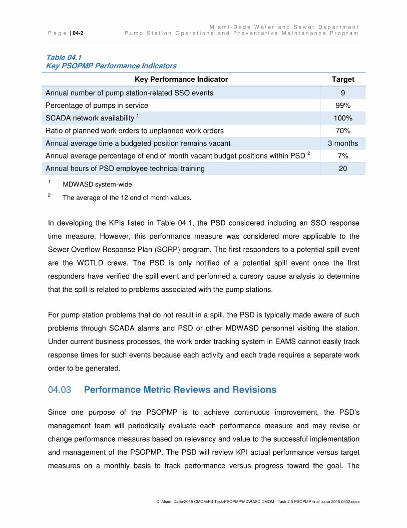
requirements. Table 04.1 presents the KPIs specified by the CD and MDWASD’s target
performance level for each which MDWASD will employ to measure, track, and report
performance of the pump station system.
M i a m i - D a d e W a t e r a n d S e w e r D e p a r t m e n t P a g e | 04-2 P u m p S t a t i o n O p e r a t i o n s a n d P r e v e n t a t i v e M a i n t e n a n c e P r o g r a m
D:\Miami Dade\2015 CMOM\PS Task\PSOPMP\MDWASD CMOM - Task 2.5 PSOPMP final issue 2015 0402.docx
Table 04.1 Key PSOPMP Performance Indicators
Key Performance Indicator Target
Annual number of pump station-related SSO events 9
Percentage of pumps in service 99%
SCADA network availability 1 100%
Ratio of planned work orders to unplanned work orders 70%
Annual average time a budgeted position remains vacant 3 months
Annual average percentage of end of month vacant budget positions within PSD 2 7%
Annual hours of PSD employee technical training 20
1 MDWASD system-wide.
2 The average of the 12 end of month values.
In developing the KPIs listed in Table 04.1, the PSD considered including an SSO response
time measure. However, this performance measure was considered more applicable to the
Sewer Overflow Response Plan (SORP) program. The first responders to a potential spill event
are the WCTLD crews. The PSD is only notified of a potential spill event once the first
responders have verified the spill event and performed a cursory cause analysis to determine
that the spill is related to problems associated with the pump stations.
For pump station problems that do not result in a spill, the PSD is typically made aware of such
problems through SCADA alarms and PSD or other MDWASD personnel visiting the station.
Under current business processes, the work order tracking system in EAMS cannot easily track
response times for such events because each activity and each trade requires a separate work
order to be generated.
Performance Metric Reviews and Revisions 04.03
Since one purpose of the PSOPMP is to achieve continuous improvement, the PSD’s
management team will periodically evaluate each performance measure and may revise or
change performance measures based on relevancy and value to the successful implementation
and management of the PSOPMP. The PSD will review KPI actual performance versus target
measures on a monthly basis to track performance versus progress toward the goal. The
M i a m i - D a d e W a t e r a n d S e w e r D e p a r t m e n t P u m p S t a t i o n O p e r a t i o n s a n d P r e v e n t a t i v e M a i n t e n a n c e P r o g r a m P a g e | 04-3
D:\Miami Dade\2015 CMOM\PS Task\PSOPMP\MDWASD CMOM - Task 2.5 PSOPMP final issue 2015 0402.docx
monthly report reviews will be designed to identify areas where additional resources or attention
is required to meet the annual target.
A semi-annual review will be conducted to determine if more wide-spread program-level
modifications may be needed to meet overall system goals.
On an annual basis, the overall performance will be assessed and appropriate corrective
measures identified and implemented to improve performance. The PSD’s management team
annual review will assess trends and needs for adjustments to preventative maintenance
schedules and staffing and funding levels. These annual reviews may also drive modification of
other CMOM Program element changes or revisions.
The PSD management review team responsible for periodic performance measure reviews will
include:
• The PSD Division Chief,
• The PSD Assistant Superintendents, and
• The Trade Supervisors from each Maintenance Service Area.
For semi-annual reviews, the Assistant Director Wastewater is included. For Annual reviews,
both the Assistant Director Wastewater and the Deputy Director of Operations are included.

M i a m i - D a d e W a t e r a n d S e w e r D e p a r t m e n t P a g e | 04-4 P u m p S t a t i o n O p e r a t i o n s a n d P r e v e n t a t i v e M a i n t e n a n c e P r o g r a m
D:\Miami Dade\2015 CMOM\PS Task\PSOPMP\MDWASD CMOM - Task 2.5 PSOPMP final issue 2015 0402.docx
THIS PAGE LEFT INTENTIONALLY BLANK
M i a m i - D a d e W a t e r a n d S e w e r D e p a r t m e n t P u m p S t a t i o n O p e r a t i o n s a n d P r e v e n t a t i v e M a i n t e n a n c e P r o g r a m P a g e | 05-1
d:\miami dade\2015 cmom\ps task\psopmp\mdwasd cmom - task 2.5 psopmp final issue 2015 0402.docx
Pump Station Maintenance 05.
Section 5 briefly outlines PSD’s routine maintenance activities. The subsections are organized
to generally follow the contents of Section 19(f)(i) through 19(f)(iii) as follows:
• Section 05.01, Means and Modes of Communication, addresses CD Section 19(f)(i).
• Section 05.02, Pump Station Technical Specifications, addresses CD Section 19(f)(ii).
• Section 05.03, Updating Pump Station Specifications, addresses the continuous
improvement procedures that will be required under the PSOPMP’s phased
implementation plan to fully address CD Section 19(f)(ii).
• Section 05.04, Pump Station Monitoring Systems, addresses CD Section 19(f)(iii).
Means and Modes of Communication 05.01
The MDWASD wastewater collection system has one permanently manned pump station,
Master Pump Station 0001. Master Pump Station 0002 has been automated and is no longer
manned 24 hours per day. Operation and maintenance of Master Pump Stations 0001 and 0002
falls under the Wastewater Treatment and Maintenance Division. Regional/Booster Pump
Stations 187, 300, 307, 536, 559, and 1310 are manned depending on system requirements. As
part of the implementation phase of the PSOPMP, an independent analysis of the proper
communication technology to be used in the future will be completed.
05.01.1 Personnel Communications
The primary means of communication between field crews and management personnel are
direct telephone lines, cellular phones (i.e., personal cell phones), and radio. PSD utilizes three
radio groups to facilitate communications. Radio communications are typically routed through
the Communications Center, which is located at the Douglas Road main office. Currently, radio
communication is the preferred method of communication because of the ability to go back and
review recorded messages and track information about the transmission. Since the radio
system has been taken over by the Police Department, the ability to review historical information
has been cumbersome and inefficient. If the Communications Center has the recording, the
M i a m i - D a d e W a t e r a n d S e w e r D e p a r t m e n t P a g e | 05-2 P u m p S t a t i o n O p e r a t i o n s a n d P r e v e n t a t i v e M a i n t e n a n c e P r o g r a m
d:\miami dade\2015 cmom\ps task\psopmp\mdwasd cmom - task 2.5 psopmp final issue 2015 0402.docx
historical information can be provided, but there are times when the Police Department either
are unable to provide the information or getting the information is not timely.
Work order communications rely heavily on the Enterprise Asset Management System (EAMS).
The PSD Planners/Schedulers generate EAMS work orders for routine and preventative
maintenance at frequencies described in later sections of this PSOPMP. EAMS also tracks
unplanned, corrective, and emergency work orders that are generated by supervisors or the
Communications Center. PSD maintenance staff generate work orders that are reviewed and
assigned by supervisors to the appropriate resources. As the PSD implements the planned
predictive maintenance activities under the CD, the EAMS work order system will be enhanced
and extended to predictive maintenance activities.
Routine and preventative maintenance activities for PSD are documented by hand-written
standardized forms, which are then scanned and attached to the correlating EAMS work order
for closure. For the SCADA Section, routine and preventative maintenance activities are
documented using digital hand held devices that allow the crew to pull up and check off a list of
maintenance items. Upon completion of the checklist items, the EAMS work order is closed.
05.01.2 Equipment Communications
A Supervisory Control and Data Acquisition (SCADA) system is used to facilitate communication
of equipment alarms and operating conditions. The system allows remote monitoring, data
capture, and control of pumps stations.
The SCADA system monitors, transmits, and records data on various pump station parameters
as listed at the end of this subsection. All MDWASD owned and operated wastewater pump
stations, have SCADA installed. All new donated stations have SCADA installed within 6
months after MDWASD becomes operationally responsible, as required by the Consent Decree.
The Communications Center has access to remotely control all pump stations via SCADA;
however, since they are not part of the PSD and lack operational knowledge, they are prohibited
from doing so unless given specific instructions by a PSD Supervisor. During implementation,
the PSD plans to move forward with activating the staffing plan, as defined in Section 09,
M i a m i - D a d e W a t e r a n d S e w e r D e p a r t m e n t P u m p S t a t i o n O p e r a t i o n s a n d P r e v e n t a t i v e M a i n t e n a n c e P r o g r a m P a g e | 05-3
d:\miami dade\2015 cmom\ps task\psopmp\mdwasd cmom - task 2.5 psopmp final issue 2015 0402.docx
Staffing and Funding Plan, to assume the operational monitoring of the pump stations by
creating positions for trained SCADA operators and expanding to multiple shifts. These staffing
changes will enable the PSD to make informed decisions about the system and improve
reaction time to alarms in the system.
The SCADA system monitors the following parameters:
• Elapsed run times per pump,
• Total run times by unit,
• Number of starts,
• Discharge pressure,
• Wet well level,
• Pump indication,
• Calculated flow,
• Rainfall gage data, and
• Generator indication.
SCADA alarm points include:
• Control unit (RTU) battery,
• Power (AC) failure,
• High level,
• Low level,
• Station flooding,
• Intrusion,
• High pressure (suction & discharge),
• Pump failure, and
• Other abnormal condition(s) depending on the facility.
M i a m i - D a d e W a t e r a n d S e w e r D e p a r t m e n t P a g e | 05-4 P u m p S t a t i o n O p e r a t i o n s a n d P r e v e n t a t i v e M a i n t e n a n c e P r o g r a m
d:\miami dade\2015 cmom\ps task\psopmp\mdwasd cmom - task 2.5 psopmp final issue 2015 0402.docx
Pump Station Technical Specifications 05.02
The PSD system has several types of pump stations as defined below. Stations are organized
into one of four maintenance service areas: North, Central West, Central East, and South.
Master Stations. A Master Station is a type A wet well / dry well pump station with a building
housing five or more large pumps (greater than 25 BHP each). Master Stations pump into large
force mains that feed directly to a treatment plant. Currently, MDWASD has two master stations
which pump directly into the Central District WWTP: Master Pump Station 0001 and Master
Pump Station 0002. Design is currently underway for the addition of a sixth pump at Master
Pump Station 0002. As previously indicated, the master pump stations are considered influent
pump stations and are operated and maintained by the WWTPs. The master pump stations will
be addressed in the WWTP Operations and Maintenance Program.
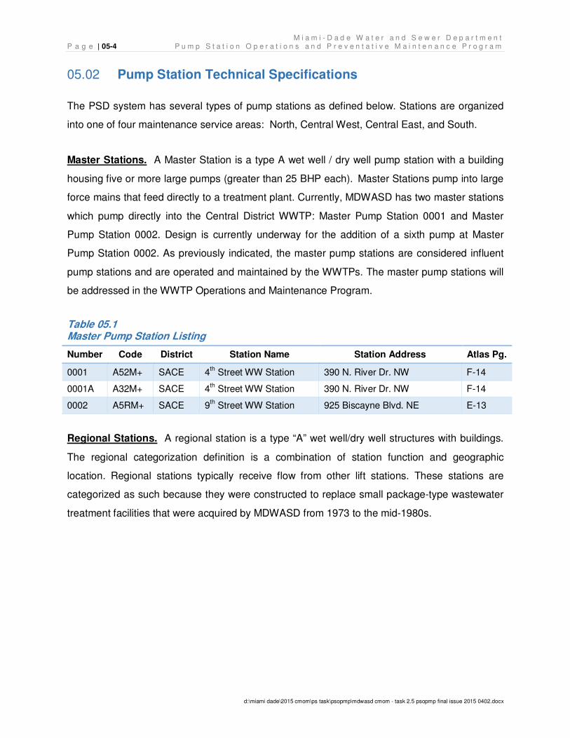
Table 05.1 Master Pump Station Listing
Number Code District Station Name Station Address Atlas Pg.
0001 A52M+ SACE 4th Street WW Station 390 N. River Dr. NW F-14
0001A A32M+ SACE 4th Street WW Station 390 N. River Dr. NW F-14
0002 A5RM+ SACE 9th Street WW Station 925 Biscayne Blvd. NE E-13
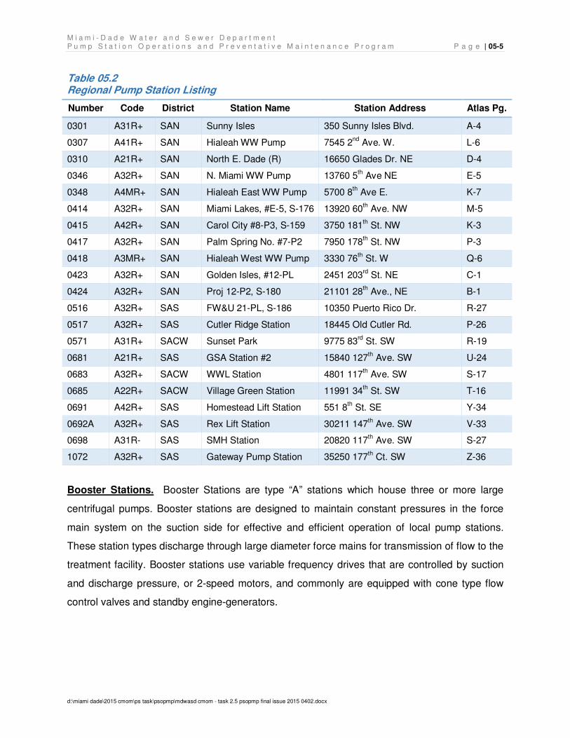
Regional Stations. A regional station is a type “A” wet well/dry well structures with buildings.
The regional categorization definition is a combination of station function and geographic
location. Regional stations typically receive flow from other lift stations. These stations are
categorized as such because they were constructed to replace small package-type wastewater
treatment facilities that were acquired by MDWASD from 1973 to the mid-1980s.
M i a m i - D a d e W a t e r a n d S e w e r D e p a r t m e n t P u m p S t a t i o n O p e r a t i o n s a n d P r e v e n t a t i v e M a i n t e n a n c e P r o g r a m P a g e | 05-5
d:\miami dade\2015 cmom\ps task\psopmp\mdwasd cmom - task 2.5 psopmp final issue 2015 0402.docx
Table 05.2 Regional Pump Station Listing
Number Code District Station Name Station Address Atlas Pg.
0301 A31R+ SAN Sunny Isles 350 Sunny Isles Blvd. A-4
0307 A41R+ SAN Hialeah WW Pump 7545 2nd
Ave. W. L-6
0310 A21R+ SAN North E. Dade (R) 16650 Glades Dr. NE D-4
0346 A32R+ SAN N. Miami WW Pump 13760 5th Ave NE E-5
0348 A4MR+ SAN Hialeah East WW Pump 5700 8th Ave E. K-7
0414 A32R+ SAN Miami Lakes, #E-5, S-176 13920 60th Ave. NW M-5
0415 A42R+ SAN Carol City #8-P3, S-159 3750 181th St. NW K-3
0417 A32R+ SAN Palm Spring No. #7-P2 7950 178th St. NW P-3
0418 A3MR+ SAN Hialeah West WW Pump 3330 76th St. W Q-6
0423 A32R+ SAN Golden Isles, #12-PL 2451 203rd
St. NE C-1
0424 A32R+ SAN Proj 12-P2, S-180 21101 28th Ave., NE B-1
0516 A32R+ SAS FW&U 21-PL, S-186 10350 Puerto Rico Dr. R-27
0517 A32R+ SAS Cutler Ridge Station 18445 Old Cutler Rd. P-26
0571 A31R+ SACW Sunset Park 9775 83rd
St. SW R-19
0681 A21R+ SAS GSA Station #2 15840 127th Ave. SW U-24
0683 A32R+ SACW WWL Station 4801 117th Ave. SW S-17
0685 A22R+ SACW Village Green Station 11991 34th St. SW T-16
0691 A42R+ SAS Homestead Lift Station 551 8th St. SE Y-34
0692A A32R+ SAS Rex Lift Station 30211 147th Ave. SW V-33
0698 A31R- SAS SMH Station 20820 117th Ave. SW S-27
1072 A32R+ SAS Gateway Pump Station 35250 177th Ct. SW Z-36
Booster Stations. Booster Stations are type “A” stations which house three or more large
centrifugal pumps. Booster stations are designed to maintain constant pressures in the force
main system on the suction side for effective and efficient operation of local pump stations.
These station types discharge through large diameter force mains for transmission of flow to the
treatment facility. Booster stations use variable frequency drives that are controlled by suction
and discharge pressure, or 2-speed motors, and commonly are equipped with cone type flow
control valves and standby engine-generators.
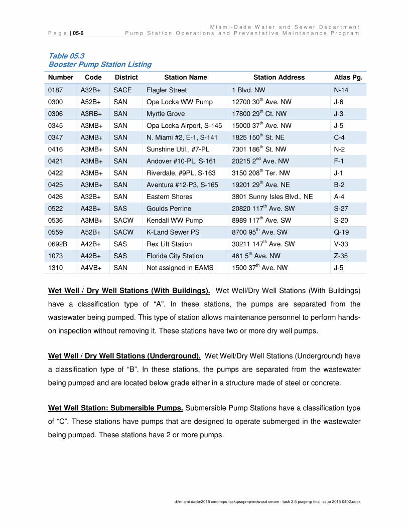
M i a m i - D a d e W a t e r a n d S e w e r D e p a r t m e n t P a g e | 05-6 P u m p S t a t i o n O p e r a t i o n s a n d P r e v e n t a t i v e M a i n t e n a n c e P r o g r a m
d:\miami dade\2015 cmom\ps task\psopmp\mdwasd cmom - task 2.5 psopmp final issue 2015 0402.docx
Table 05.3 Booster Pump Station Listing
Number Code District Station Name Station Address Atlas Pg.
0187 A32B+ SACE Flagler Street 1 Blvd. NW N-14
0300 A52B+ SAN Opa Locka WW Pump 12700 30th Ave. NW J-6
0306 A3RB+ SAN Myrtle Grove 17800 29th Ct. NW J-3
0345 A3MB+ SAN Opa Locka Airport, S-145 15000 37th Ave. NW J-5
0347 A3MB+ SAN N. Miami #2, E-1, S-141 1825 150th St. NE C-4
0416 A3MB+ SAN Sunshine Util., #7-PL 7301 186th St. NW N-2
0421 A3MB+ SAN Andover #10-PL, S-161 20215 2nd
Ave. NW F-1
0422 A3MB+ SAN Riverdale, #9PL, S-163 3150 208th Ter. NW J-1
0425 A3MB+ SAN Aventura #12-P3, S-165 19201 29th Ave. NE B-2
0426 A32B+ SAN Eastern Shores 3801 Sunny Isles Blvd., NE A-4
0522 A42B+ SAS Goulds Perrine 20820 117th Ave. SW S-27
0536 A3MB+ SACW Kendall WW Pump 8989 117th Ave. SW S-20
0559 A52B+ SACW K-Land Sewer PS 8700 95th Ave. SW Q-19
0692B A42B+ SAS Rex Lift Station 30211 147th Ave. SW V-33
1073 A42B+ SAS Florida City Station 461 5th Ave. NW Z-35
1310 A4VB+ SAN Not assigned in EAMS 1500 37th Ave. NW J-5
Wet Well / Dry Well Stations (With Buildings). Wet Well/Dry Well Stations (With Buildings)
have a classification type of “A”. In these stations, the pumps are separated from the
wastewater being pumped. This type of station allows maintenance personnel to perform hands-
on inspection without removing it. These stations have two or more dry well pumps.
Wet Well / Dry Well Stations (Underground). Wet Well/Dry Well Stations (Underground) have
a classification type of “B”. In these stations, the pumps are separated from the wastewater
being pumped and are located below grade either in a structure made of steel or concrete.
Wet Well Station: Submersible Pumps. Submersible Pump Stations have a classification type
of “C”. These stations have pumps that are designed to operate submerged in the wastewater
being pumped. These stations have 2 or more pumps.
M i a m i - D a d e W a t e r a n d S e w e r D e p a r t m e n t P u m p S t a t i o n O p e r a t i o n s a n d P r e v e n t a t i v e M a i n t e n a n c e P r o g r a m P a g e | 05-7
d:\miami dade\2015 cmom\ps task\psopmp\mdwasd cmom - task 2.5 psopmp final issue 2015 0402.docx
Wet Well Station: Submersible Pumps with Building. Submersible Pumps with Building
have a classification type of “D”. These stations are submersible pump stations that are located
within a building.
Wet Well Station: Self-priming Pumps Above Ground. Self-priming Pumps Above Ground
have a classification type of “E”. These stations have self-priming pumps mounted above
ground (or partially above ground). They are typically fenced in for security, but have no
buildings or enclosures.
Miscellaneous Stations: Stations that do not fall within the above listed station classes
including pneumatic ejector dry well stations, air compressor stations, and vent stations have a
classification type of “F”. This class is being phased out.
Appendix B, EAMS Pump Station Database, is an example of the PSD-maintained stations
organized by classification.
Updating Pump Station Specifications 05.03
MDWASD has the ability to enter pump station asset data into the Infor EAM System (EAMS)
database for ease of data retrieval and to have a common data source. The EAMS database
can be used to track systems, assets, inventories, work orders, etc. EAMS manages data by
packaging it into three different types of entities: systems, positions, and assets. A “system” is a
compilation of features that function as one entity with a single function. System entities can
contain other entities, including position entities and other system entities. “Position” entities are
used as placeholders for “asset” entities, and define the specific tasks needed to achieve a
system goal. EAMS is a hierarchical system with the system entities at the top level, and the
assets at the bottom level. The hierarchy of entities within a system entity is known as the
“structure” and it defines sub-systems, positions, and assets that are part of the parent system.
Assets can be moved within the system from position to position, or they can be moved to a
storeroom as inventory items or to a garage for repair. A “position” entity will describe what type
of assets that particular position should accept. The “asset” will describe a specific piece of
equipment down to the serial number. Assets should be assigned only to a position that
M i a m i - D a d e W a t e r a n d S e w e r D e p a r t m e n t P a g e | 05-8 P u m p S t a t i o n O p e r a t i o n s a n d P r e v e n t a t i v e M a i n t e n a n c e P r o g r a m
d:\miami dade\2015 cmom\ps task\psopmp\mdwasd cmom - task 2.5 psopmp final issue 2015 0402.docx
matches its characteristics. Each asset, position, or system can potentially have a class
associated with it. A class has custom fields associated with it, and each time the class is
associated with an entity, EAMS will apply those custom fields to the item so that information
can be captured by the end user. The assignment of an asset to a position has to be done
manually.
Each entity in EAMS has a set of standard fields, and user-defined custom fields, that capture
the engineer’s requirement that is pertinent to that particular entity. This capability allows a
pump station to be described at a high level as a “system” entity, and at a low level in the
“position” entities where specific component-level details are described. For example, at the
“system” level the pump station can have a field such as “number of pumps”, voltage,
emergency portable generator kilowatt requirement, and station design capacity, which is more
representative of the overall system operation. At the pump “position” level, the pump class
identifies characteristics such as the pump total capacity, net capacity, horsepower, revolutions
per minute (RPM), impeller size, impeller outer diameter (OD), total dynamic head (TDH), flow,
etc. At the “asset” level, a pump asset will contain the same parameters as the “position” and
will also include other asset-specific fields such as serial number, manufacturer, year built, etc.
Pump stations are entered into the EAMS database as “system” entities, and these in turn are
part of a maintenance service area “system” entity, which are ultimately part of the parent PSD
“system” entity. The four maintenance service areas are described as Service Area North
(SAN), Service Area Central East (SACE), Service Area Central West (SACW), and Service
Area South (SAS). In EAMS pump station system entities are identified by their class field
“PUMPST”, and belong to the Equipment Owner field “830” which refers to the PSD. Appendix
B, EAMS Pump Station Database, contains a figure depicting a typical pump station asset
hierarchy within EAMS.
Currently, only a limited number of EAMS pump station data fields are populated. The PSOPMP
implementation plan will include the proper development of EAMS to handle capturing pertinent
data for pump station components and subsequent field data acquisition activities to verify the
currently populated data and to acquire new data. During field data acquisition activities, the
following EAMS data fields will be filled in as part of the requirement for a technical specification
M i a m i - D a d e W a t e r a n d S e w e r D e p a r t m e n t P u m p S t a t i o n O p e r a t i o n s a n d P r e v e n t a t i v e M a i n t e n a n c e P r o g r a m P a g e | 05-9
d:\miami dade\2015 cmom\ps task\psopmp\mdwasd cmom - task 2.5 psopmp final issue 2015 0402.docx
for each of the MDWASD-owned pump stations. The following list identifies a sample of some of
the parameters which will be collected. A more complete list will be developed with PSD during
the process of implementation.
• Station number,
• Address,
• Atlas page,
• Station classification,
• Station capacity (gpd),
• Number of pumps,
• Station speed,
• Station type,
• Station horsepower,
• Station phase,
• Station voltage.
The following list identifies some of the detailed information that the current EAMS database is
lacking:
• Equipment type/class,
• Manufacturer,
• Model number,
• Equipment type,
• Impeller size,
• Impeller unit measure,
• Impeller interior diameter (ID),
• Total dynamic head (feet),
• Pump capacity (gpm),
M i a m i - D a d e W a t e r a n d S e w e r D e p a r t m e n t P a g e | 05-10 P u m p S t a t i o n O p e r a t i o n s a n d P r e v e n t a t i v e M a i n t e n a n c e P r o g r a m
d:\miami dade\2015 cmom\ps task\psopmp\mdwasd cmom - task 2.5 psopmp final issue 2015 0402.docx
• Speed (rpm), and
• Motor (hp).
Screen shots of the EAMS pump station data currently populated is in Appendix B, EAMS Pump
Station Database.
The EAMS data acquisition implementation will be completed in a three step process:
1. Properly analyze the viability of EAMS and then move forward with a full implementation
of an asset management system that can efficiently capture and report detailed
information about the PSD system. The implementation of EAMS will include bar coding
of all assets within PSD’s responsibility and a system that will address repairable spares.
2. Complete a total system inventory utilizing a mobile data acquisition tool (i.e. laptop,
tablet, etc.) to populate the existing list of pump stations with detailed information
necessary for PSD to operate and maintain their assets. If consultants or vendors are
used for the data acquisition, PSD staff time will also be required to accompany the
contractors to each station and assist in equipment access and operations.
3. Develop a protocol to update the database with replaced components due to
maintenance or rehabilitation to include the addition of new pump stations to the system
to ensure the database remains populated with accurate inventory information.
The EAMS data acquisition implementation process will be coordinated with the implementation
of the PSIP, SSAMP, IMS, and GIS CMOM Programs. In general terms, the CD requires:
• The PSIP to develop corrective actions for pump stations not in compliance with
NAPOT requirements;
• The SSAMP to perform a current condition assessment of sewer system components,
including the pump station components;
• The IMS to establish management, operations, and maintenance reporting to evaluate
O&M, customer service, track scheduled O&M, etc.
• The GIS to import new assets into the appropriate GIS layer within 90 days.
M i a m i - D a d e W a t e r a n d S e w e r D e p a r t m e n t P u m p S t a t i o n O p e r a t i o n s a n d P r e v e n t a t i v e M a i n t e n a n c e P r o g r a m P a g e | 05-11
d:\miami dade\2015 cmom\ps task\psopmp\mdwasd cmom - task 2.5 psopmp final issue 2015 0402.docx
Pump Station Monitoring Systems 05.04
As noted in Section 05.01.2, MDWASD uses the SCADA system to remotely monitor and
control all pump stations within the WCTS.
Primary pump station automatic level controls, including bubblers, and submersible pressure
transducers used in conjunction with floats as backups, are used to measure the level of
wastewater in a wet well and activate/deactivate pumps via auxiliary control equipment, which
converts the measurement from the primary control into a signal for a pump to start, stop, or
change speed. These secondary controls convert a sensing signal into a mechanical or
electrical signal which in turn activates a low voltage motor relay to start or stop motors, or
signals to change ranges on variable speed equipment. Starting and stopping pumps can be
performed remotely through the SCADA system to control both the discharge and suction
pressure of the booster pump stations, to adjust total dynamic head in the system, and to assist
in redirecting flow when necessary.
One of the primary functions of the SCADA system is to transmit alarms of equipment
malfunctions. Alarm notifications typical generate “unscheduled maintenance or emergency”
work order responses. The system is also used as a Predictive Maintenance tool (i.e., as in the
case of pump operating time trend analysis example cited in the below paragraph). The data
received from SCADA can be queried to generate various reports which are used to analyze
overall system operation and identify individual pump station anomalies and repeat failures.
SCADA historical data records are stored in two separate databases. PSD uses 3-minute data
and one-hour data to proactively identify potential problems with a pump station. Special
attention is paid to pump operating time increases or when pumps exhibit uneven run times.
The SCADA Section has recommended development of a SCADA master plan to address
issues such as appropriate technology upgrades, data management, data analysis
improvements, historical databases, etc. Implementation of the SCADA master plan will be
coordinated with MDWASD’s existing Pump Station Remote Monitoring (PSRM) Program under
CD Paragraph 18(b). There is a need to address interdependencies with new CMOM programs
identified in CD Paragraph 19.

M i a m i - D a d e W a t e r a n d S e w e r D e p a r t m e n t P a g e | 05-12 P u m p S t a t i o n O p e r a t i o n s a n d P r e v e n t a t i v e M a i n t e n a n c e P r o g r a m
d:\miami dade\2015 cmom\ps task\psopmp\mdwasd cmom - task 2.5 psopmp final issue 2015 0402.docx
THIS PAGE LEFT INTENTIONALLY BLANK
M i a m i - D a d e W a t e r a n d S e w e r D e p a r t m e n t P u m p S t a t i o n O p e r a t i o n s a n d P r e v e n t a t i v e M a i n t e n a n c e P r o g r a m P a g e | 06-13
d:\miami dade\2015 cmom\ps task\psopmp\mdwasd cmom - task 2.5 psopmp final issue 2015 0402.docx
Pump Station Emergency Maintenance 06.
The PSD characterizes emergency maintenance operations as unplanned/unscheduled or
corrective activities that require immediate action in order to protect and preserve public health
and safety. Emergencies are typically caused by situations that hinder the operation of the
pump stations by reducing or interrupting their ability to transport sewage. The majority of
emergency maintenance operations involve minor localized problems which affect a small area
and which are addressed by a limited number of service crews. During times of significant storm
events or major blackouts, the PSD will institute the Overflow Prevention Plan (OPP), effectively
mobilizing and placing into high alert the entire PSD. The OPP is essentially a plan for more
“extreme” emergencies such as a hurricane or a wide-spread flooding event.
Pump stations are critical for the proper transport of sewage through the WCTS. A nonfunctional
pump station will cause sewage to accumulate in the pump station’s wet wells and will cause an
upstream backup which will result in overflows. For this reason, pump stations are designed
with a number of safety mechanisms such as redundant pumps and, in the case of major pump
stations, backup electric power generators. All of the pump stations in the MDWASD system
have an N-1 design, where N represents the number of pumps needed to effectively handle the
permitted flow. Therefore, if one of the mechanical pump systems becomes non-functional,
there is at least one on-site backup pump to takeover. Unlike the mechanical redundancy, not
all pump stations have backup electric power generators; therefore, the stations without
generators are at risk of complete shutdown if there is a power outage as portable generators
will have to be transported from elsewhere.
It should be noted that most overflows are caused by problems encountered on the wastewater
collection lines such as grease blockages and broken mainlines. These problems with the
WCTS fall under the responsibility of the Wastewater Collection and Transmission Line Division
(WCTLD). Nevertheless, the PSD coordinates emergency responses with the WCTLD where
there is overlap or where both need to work together to resolve an emergency situation caused
by pump station problems. This cooperative effort is especially common when responding to
spill events where a pump station problem causes an overflow at an upstream manhole. In
those cases where the pump station was determined to be the cause of the overflow, WCTLD is
M i a m i - D a d e W a t e r a n d S e w e r D e p a r t m e n t P a g e | 06-14 P u m p S t a t i o n O p e r a t i o n s a n d P r e v e n t a t i v e M a i n t e n a n c e P r o g r a m
d:\miami dade\2015 cmom\ps task\psopmp\mdwasd cmom - task 2.5 psopmp final issue 2015 0402.docx
responsible for the spill clean-up activities, while PSD is responsible for the final spill reporting
coordination with the Communications Center.
Sewer Overflow Response Plan Overview 06.01
As part of the current Consent Decree requirements, MDWASD is developing a Sewer Overflow
Response Plan (SORP). The SORP will detail the regulatory, public notification, and reporting
requirements as required by the Consent Decree. This SORP will replace the existing program
for identifying and reporting SSOs.
Problem Identification 06.02
Due to the sensitivity of the WCTS to problems at the pump stations, any problem that could
potentially create an overflow is considered an emergency and PSD staff responds accordingly.
As described below, PSD problems can be identified through numerous channels, including:
• SCADA alarms,
• MDWASD personnel, and
• Customer complaints or external agency personnel.
Situations that require emergency action on the part of the PSD are routed through the
Communications Center. The Communications Center is a 24-hour manned operations center
within the Security and Communications Division, which is responsible for receiving notifications
of potential problems and communicating these problems to the appropriate MDWASD
divisions. Problems can be reported to the Communications Center via telephone by members
of the public, via telephone by other agencies such as from RER-DERM, or via telephone, radio,
or the County’s intranet by personnel from within MDWASD. The Communications Center also
monitors MDWASD’s SCADA system for critical alarms requiring immediate action.
Emergency Operation Equipment and Capabilities 06.03
Critical to the ability of the PSD to mitigate emergency conditions are its portable emergency
equipment such as diesel generators and bypass pumps, both of which are trailer-mounted for
ease of transportation. Currently, the PSD is adequately equipped to handle most emergency
M i a m i - D a d e W a t e r a n d S e w e r D e p a r t m e n t P u m p S t a t i o n O p e r a t i o n s a n d P r e v e n t a t i v e M a i n t e n a n c e P r o g r a m P a g e | 06-15
d:\miami dade\2015 cmom\ps task\psopmp\mdwasd cmom - task 2.5 psopmp final issue 2015 0402.docx
situations and abnormal events such as blackouts and tropical storms that may cause localized
flooding.
06.03.1 Backup Power
The PSD relies on two types of backup power: on-site generators for larger stations such as
master, regional, and booster stations, and portable generators for smaller pump stations.
Larger stations are critical to the operation of the system and are thus expected to remain
operational during most emergency situations. The PSD uses diesel-powered on-site
generators. These installations require other ancillary equipment such as a diesel bulk storage
tank and day tank, diesel pumps, and proper ventilation equipment. Many of these activities are
maintained by other MDWASD divisions as described below.
Generators are composed of a driver component (the diesel engine) and the driven component
(the generator itself). The PSD maintains the driven components for both mobile and fixed
generators. The Wastewater Treatment and Maintenance Division maintains the driver
component for fixed generators, and the Fleet Maintenance Division maintains the driver
components for mobile generators. Approximately 180 to 190 pump stations have fixed
generators. All other stations have external generator capability for mobile emergency
generators. The PSD currently has 43 mobile trailer-mounted generators, the majority of which
are from the early 1990s or newer.
06.03.2 Portable Bypass Pumping
Portable bypass pumping equipment is utilized during catastrophic equipment failures, when a
generator is not a feasible alternative, or when a station needs to be taken out of service for
either upgrades or wet well maintenance. When in bypass, the influent to the wet well is
pumped to the surface and delivered through a valve connection in the pump station discharge
line. Valves within the station control vault would be closed to prevent backflow into the station.
Given this configuration, the pump station should operate to its design capacity while necessary
repairs are being made or until power is restored. Bypass pumps are driven by electric motor or
diesel engines. The PSD maintains bypass pumping equipment. The PSD currently has 41
mobile trailer-mounted pumps, the majority of which are from the 1990s.
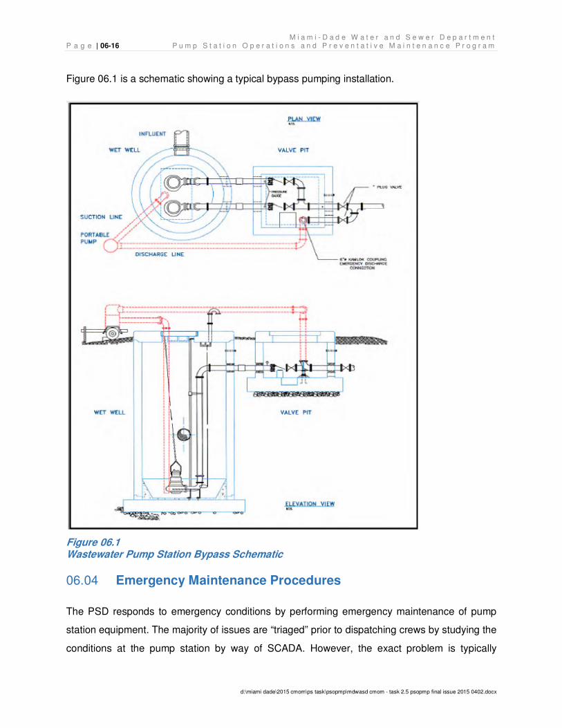
M i a m i - D a d e W a t e r a n d S e w e r D e p a r t m e n t P a g e | 06-16 P u m p S t a t i o n O p e r a t i o n s a n d P r e v e n t a t i v e M a i n t e n a n c e P r o g r a m
d:\miami dade\2015 cmom\ps task\psopmp\mdwasd cmom - task 2.5 psopmp final issue 2015 0402.docx
Figure 06.1 is a schematic showing a typical bypass pumping installation.
Figure 06.1 Wastewater Pump Station Bypass Schematic
Emergency Maintenance Procedures 06.04
The PSD responds to emergency conditions by performing emergency maintenance of pump
station equipment. The majority of issues are “triaged” prior to dispatching crews by studying the
conditions at the pump station by way of SCADA. However, the exact problem is typically
M i a m i - D a d e W a t e r a n d S e w e r D e p a r t m e n t P u m p S t a t i o n O p e r a t i o n s a n d P r e v e n t a t i v e M a i n t e n a n c e P r o g r a m P a g e | 06-17
d:\miami dade\2015 cmom\ps task\psopmp\mdwasd cmom - task 2.5 psopmp final issue 2015 0402.docx
identified after the crews arrive onsite. Examples of pump station emergency maintenance can
be categorized as:
• All pumps or motors are inoperable due to equipment failure (i.e. catastrophic failure);
• Lack of electrical power to the station;
• Failure of with instrumentation and/or controls; and
• Failure of SCADA RTU communication.
When one pump or motor becomes inoperable due to equipment failure, the operation of the
pump station is not fully inhibited given the redundant pump design prevalent in all pump
stations. Therefore, during these situations the repairs to the station can occur without the need
to install a portable bypass pump since the remaining pump(s) can handle the full permitted
flow. Catastrophic failures are instances in which a majority or all of the pumps or motors at a
particular station suffer equipment failure leading to a significant or complete loss of pumping
capacity and thus requiring the use of portable bypass pumps.
For stations that do not have onsite generators, a lack of electrical power to the station results in
a complete shutdown of the station and therefore they are completely inhibited from operating. If
the affected stations have an external generator connection, then portable generators are
installed immediately to get the stations back online. Stations with no external generator
connection require the use of bypass pumps during power loss situations. Failures of onsite
backup generators are not common; however, if a backup generator does not come online
during a power outage, the onsite electrical crew will attempt to address the problem. If the
problem cannot be fixed right away, the responding electrical crew will install a mobile generator
or request a bypass pump, depending on the availability of an external generator. In addition,
the crews will notify the Communications Center that maintenance for the fixed generator is
required by the Wastewater Treatment and Maintenance Division. The PSD crews will also
inform Florida Power & Light (FP&L) of any power outages affecting the PSD’s pump stations by
contacting FP&L’s hotline.
Problems in pump stations can also arise with instrumentation and SCADA RTU communication
issues. When a problem arises due to instrumentation such as pressure transducers, level
M i a m i - D a d e W a t e r a n d S e w e r D e p a r t m e n t P a g e | 06-18 P u m p S t a t i o n O p e r a t i o n s a n d P r e v e n t a t i v e M a i n t e n a n c e P r o g r a m
d:\miami dade\2015 cmom\ps task\psopmp\mdwasd cmom - task 2.5 psopmp final issue 2015 0402.docx
controllers, or other, the Electrical trade addresses the issue. When a problem arises due to
communication issues with the SCADA RTU, the SCADA Section technicians are currently
responsible for addressing the issue. Since the main control of the pump stations is handled by
a local station controller, a lack of communication to the SCADA RTU does not inhibit the
operation of the station; however, wet well level and all statuses depending on SCADA
transmission will not operate until the communication failure is resolved.
When any sort of equipment failure occurs, be it a pump, motor or instrumentation failure, the
onsite crews will first assess whether the PSD has the capability to handle the repairs. It should
be noted that the PSD is well-equipped to handle the majority of repairs and only in special
circumstances where special parts are not kept in stock and/or the services to be provided are
highly specialized does the PSD resort to requesting the services of outside Contractors /
Vendors.
Post-Event Analysis 06.05
Upon full implementation of the PSOPMP, the PSD will conduct monthly reviews of emergency
work resulting in an SSO event to identify “lessons learned” from the emergency situation. The
goal of these monthly reviews is to ensure proper procedures and protocols were followed and
to identify potential inadequacies associated with those procedures and protocols. The post
event analyses will ensure lessons learned are applied to minimize the potential for future
problems caused by similar conditions. The post event analyses will further ensure that if a
“temporary fix” has been applied, steps to make a proper, permanent fix are identified for
implementation. SOPs will be defined in the SORP document.
M i a m i - D a d e W a t e r a n d S e w e r D e p a r t m e n t P u m p S t a t i o n O p e r a t i o n s a n d P r e v e n t a t i v e M a i n t e n a n c e P r o g r a m P a g e | 07-1
d:\miami dade\2015 cmom\ps task\psopmp\mdwasd cmom - task 2.5 psopmp final issue 2015 0402.docx
Pump Station Preventative and Predictive Maintenance 07.
Preventative maintenance is the scheduled work performed to prevent equipment breakdown,
reduce wear, improve efficiency, and extend the life of equipment. Scheduled routine
maintenance includes the inspection, cleaning, and adjusting of equipment as necessary during
routine pump station inspections and scheduled preventative maintenance.
MDWASD currently employs an EAMS software platform that serves to automate preventative
maintenance schedules, generate and track work orders. Upon complete configuration, the
EAMS system will enable the PSD to:
• Track inventory,
• Maintain a detailed pump station infrastructure database,
• Track equipment location that is dispatched and/or brought in for service,
• Query information on individual pump station equipment,
• Generate and track work orders for:
o Scheduled Station inspections
o Preventative Maintenance (PM)
o Routine Maintenance (RM)
o Unscheduled maintenance
o Emergency maintenance
• Maintain equipment maintenance history,
• Generate reports, and
• Track maintenance cost and labor expenditures.
The PSD’s preventative maintenance program has been developed based on the following
factors:
• Equipment manufacturers' recommendations. Maintenance and overhaul
recommendations are provided for each piece of equipment by the manufactures. In the
implementation phase of this PSOPMP, it will be important to collect vendor literature
M i a m i - D a d e W a t e r a n d S e w e r D e p a r t m e n t P a g e | 07-2 P u m p S t a t i o n O p e r a t i o n s a n d P r e v e n t a t i v e M a i n t e n a n c e P r o g r a m
d:\miami dade\2015 cmom\ps task\psopmp\mdwasd cmom - task 2.5 psopmp final issue 2015 0402.docx
digitally and ensure it is stored in the EAMS associated with the respective equipment.
The literature will define the frequency of oil changes and lubrication of bearings, types
of lubricant, operating temperature ranges, pressures, flow rates, and disassembly
procedures for specific equipment maintenance or parts replacement.
As a refinement to the existing preventative maintenance/routine maintenance
methodology, once all equipment is inventoried and identified, a more accurate
equipment maintenance schedule can be developed by listing all of the manufacturers'
recommendations in sequence according to time periods. These schedules can be cross
referenced with the current preventative and routine maintenance procedures and
programmed in the EAMS to automatically generate work orders for PSD crews in
accordance with revised scheduled requirements and availability of additional PSD staff
to accommodate such revisions.
• Individual station requirements. Maintenance scheduling is dependent upon trade
and station design. Due to the time required to travel in a congested urban area, PSD
has scheduled preventative maintenance activities by station type, calendar and by
geography. Preventative maintenance activities at pump stations in close geographic
areas are scheduled at the same time so the maintenance crews can follow a defined
route that is as efficient as possible. As a part of implementation, specific frequencies of
schedules need to be adjusted to accommodate the needs and the geography of the
individual station. These items will be developed primarily from station operating
experience and will be re-evaluated annually by field crews, supervisors, and
management or when the addition of donation pump stations require changes in the
geographic grouping of the stations in that area.
• Knowledge of the system and past performance. Knowledge and experience
regarding local condition and the reliability of the existing equipment are also considered
in developing the maintenance schedules.
M i a m i - D a d e W a t e r a n d S e w e r D e p a r t m e n t P u m p S t a t i o n O p e r a t i o n s a n d P r e v e n t a t i v e M a i n t e n a n c e P r o g r a m P a g e | 07-3
d:\miami dade\2015 cmom\ps task\psopmp\mdwasd cmom - task 2.5 psopmp final issue 2015 0402.docx
Preventative Maintenance Activities and Responsibilities 07.01
Preventative and/or routine maintenance is categorized into three trades by PSD; Mechanical,
Electrical, and Structural.. The SCADA components at the pump stations have their own
preventative maintenance/reactive maintenance schedules that are performed by the SCADA
Section and are described in subsequent sections.
07.01.1 Staffing Resources and Capabilities
Appendix C, Routine and Preventative Maintenance Task Lists for the Trades, contains the
specific task lists for:
• Mechanical Routine Maintenance,
• Electrical Routine Maintenance,
• Structural Routine Maintenance.
Preventative Maintenance is done for the Mechanical and Electrical components in accordance
with the two detailed checklists provided in Appendix C. Upon implementation of the planned
wet well capital unit, wet well inspections will be performed as part of routine maintenance
inspections by all trades.
07.01.2 Service and Calibration
The equipment listed below is maintained as part of the routine and preventative maintenance
tasks described above in accordance with the routine maintenance task lists included as
Appendix C. The equipment is calibrated periodically by the PSD Electrical Maintenance
Section, the Meter Installation and Maintenance Division, and the SCADA Section as part of
MDWASD’s scheduled maintenance. These groups are responsible for calibration of the
following components to ensure data is transmitted to the SCADA system accurately. The
following subsections describe the equipment in the system that is serviced and calibrated in
accordance with their respective PM/RMs which are scheduled through EAMS.
M i a m i - D a d e W a t e r a n d S e w e r D e p a r t m e n t P a g e | 07-4 P u m p S t a t i o n O p e r a t i o n s a n d P r e v e n t a t i v e M a i n t e n a n c e P r o g r a m
d:\miami dade\2015 cmom\ps task\psopmp\mdwasd cmom - task 2.5 psopmp final issue 2015 0402.docx
Flow Meters. Flow meter maintenance is done by MDWASD’s Meter Installation and
Maintenance Division. Meter Installation and Maintenance maintains 37 flow meters associated
with the WCTS. The wastewater meters fall into three specific categories based on purpose:
• Wholesale meters, which record flow from Volume Service Customers,
• Retail meters, which record flow from commercial or industrial customers, and
• Monitor meters, which record flow from regional pump stations and booster pump
stations and from strategic points within the wastewater system.
For pump stations, there are 11 wholesale meters, 4 retail meters, and 22 monitor meters.
These pump station monitor meters are critical in maintaining and operating the overall system
flow direction and performance of the system. Meter maintenance is performed by the Meter
Installation and Maintenance Section.
The Meter Installation and Maintenance Section is responsible for performing the following
preventative maintenance activities on the meters in the wastewater system:
• Monthly: check condition of station, check 4-20 mA output and check calibration using
flow simulator.
• Semiannual: conduct the monthly check plus perform a flow comparison (primary vs.
secondary meters).
A complete meter inventory list which includes flow meter type, manufacture, size, and location
sorted for pump stations only is included in Appendix D, Pump Station Meter Inventory.
Liquid Level Sensors. MDWASD currently uses two types of level controls, Bubbler System
and Submersible Level Transducers. Float balls (float level switches) are used as backup level
sensors for high level alarms and controls. Level sensors are part of the level control system
that operate the pumps “On” and “Off”. Additional components of the system include controllers
and transmitters. The sensor can be cleaned and calibrated, but are typically replaced when
they do not operate properly. Controllers and transmitters are also typically replaced when they
fail.
M i a m i - D a d e W a t e r a n d S e w e r D e p a r t m e n t P u m p S t a t i o n O p e r a t i o n s a n d P r e v e n t a t i v e M a i n t e n a n c e P r o g r a m P a g e | 07-5
d:\miami dade\2015 cmom\ps task\psopmp\mdwasd cmom - task 2.5 psopmp final issue 2015 0402.docx
Calibration of and between these units is performed during the Electrical Routine Maintenance
Task List scheduled maintenance. The level sensors are checked for air leaks, pressure
regulator set points, and alarm set points, as applicable to the sensor type. Crews ensure that
pumps start and stop according to station's operating parameters and that level reading gauges
are accurate and concur with SCADA readings. Notations of adjustments made to Level
Controller are documented in the inspection forms and attached to the EAMS work order. As
previously indicated, the Electrical Routine Maintenance Task List is included in Appendix C.
Bubbler System. Compressor bubbler systems are equipped with bubbler tube purge, tank
moisture dump, system status indication, and system fault alarms. The unit provides a 4 to 20
mA analog output representing level for use by other devices to perform pump control or
telemetry functions. The modular construction of this device allows for easy field servicing of the
sub-assembly components.
Submersible Level Transducer. Submersible level transducers reliably measure the level of
wastewater based upon the hydrostatic pressure of the liquid above the submerged sensor’s
diaphragm. The transducer provides an output signal directly proportional to the sensed level
over the calibrated range of the sensing element.
Floats. Floats are normally used as back-up to the primary means of level controls as listed
above. Typically, a series of floats are positioned at varying levels within the wet well to trigger
alarm positions.
Alarm Sensors. SCADA equipment is calibrated or replaced on a SCADA maintenance
scheduled. Alarm testing and is also covered by the Electrical Routine Maintenance Task List
schedule. Alarms are checked, adjusted, or repaired as necessary to ensure proper functioning.
The Electrical crew coordinates with SCADA and/or Communications Center to ensure that
alarms are being received. External (local) visual alarms are also checked.
Elapsed Time Meters. Elapsed Time Meters (ETM) work in conjunction with the motor starters
to record the run time duration of each pump. ETMs are inspected during both Electrical and
M i a m i - D a d e W a t e r a n d S e w e r D e p a r t m e n t P a g e | 07-6 P u m p S t a t i o n O p e r a t i o n s a n d P r e v e n t a t i v e M a i n t e n a n c e P r o g r a m
d:\miami dade\2015 cmom\ps task\psopmp\mdwasd cmom - task 2.5 psopmp final issue 2015 0402.docx
Mechanical Routine Maintenance Task List schedules. Readings are taken and compared to the
transmitted SCADA data base. The ETMs are replaced as necessary.
Remote Sensing Equipment. Remote sensing equipment include a wide range of sensor
options such as pressure switches, level sensor, pump run frequency and duration, pump motor
current usage, sump pump activation, and alarms regarding lift station problems. The PSD
Electrical trade preforms preventative maintenance, which test and record the electrical
insulation level (meGOhms, amperage, and voltage of the above listed equipment.
07.01.3 Predictive Maintenance
Currently, the only predictive maintenance (PdM) being performed is routine review of ETM
pump run time trends and transformers oil analysis.
The ETM installed on every pump is the best early warning sign of trouble at pump stations. In
most properly operating pump stations, the pumps will be operating within a few percent of the
run time to each other regardless of the number of pumps in the station. For the vast majority of
single speed, automatic alternating pump stations in MDWASD’s WCTS, this early warning
system can help focus maintenance issues in an early, low manpower procedure. The
accumulated data from the ETM readings, which is monitored for NAPOT compliance, is
routinely tracked to determine if deterioration is occurring in any of the pumps in the system.
The majority of pump clogging issues surround the wide variety of non-flushable materials now
being discharged into the WCTS.
Under full implementation of the PSOPMP, additional predictive maintenance activities will be
performed. The purpose of the additional PdM activities is to reduce unnecessary service to
critical equipment which may otherwise be rebuilt or replaced simply due to fatigue. Typically,
items that are identified as requiring the more proactive predictive maintenance take longer to
service and are critical to pump station operation. These items are usually difficult to remove
from service without affecting the operations of the facility. Instead of servicing this equipment
on a routine schedule, various indicators are used to determine the need for the rebuild or
replacement of equipment.
M i a m i - D a d e W a t e r a n d S e w e r D e p a r t m e n t P u m p S t a t i o n O p e r a t i o n s a n d P r e v e n t a t i v e M a i n t e n a n c e P r o g r a m P a g e | 07-7
d:\miami dade\2015 cmom\ps task\psopmp\mdwasd cmom - task 2.5 psopmp final issue 2015 0402.docx
PdM is used for the early detection and prevention of equipment defects that could lead to
unplanned downtime or costs. This is done when equipment is in operation to determine current
equipment status and detect defects early. Through discussions with PSD, implementation will
include the addition of four techniques: vibration analysis, thermal imaging, insulation
resistance (i.e., the Megger Test), and oil analysis; all of which are used to find defects not
typically discovered during routine or preventative maintenance inspections.
Vibration Analysis. One of the most revealing pieces of information regarding the condition of
rotating machinery is a vibration signature. Vibration consists of amplitude, frequency, and
direction. These provide the information needed to diagnose the machine's condition.
PSD maintains mostly centrifugal pumps that will generate pumping frequencies due to flow,
cavitation, and recirculation (i.e., number of vanes multiplied by rpm for centrifugal pumps).
Pumps also have other mechanical problems such as imbalance, misalignment, looseness,
worn bearings, pipe strain, and resonance that cause vibration. Monitoring will include:
• Severity/amplitude,
• Frequency,
• Displacement,
• Velocity, and
• Acceleration.
Thermal Imaging. The objective of thermal imaging is to identify thermal variations, which may
indicate:
• Hot bearings,
• Valve leaks,
• Plugged coolers, or
• Electrical faults.
As shown in the example thermal imaging scan in Figure 07.1, thermal imaging uses an infrared
camera to measure equipment surface temperatures. Comparing thermal signatures with
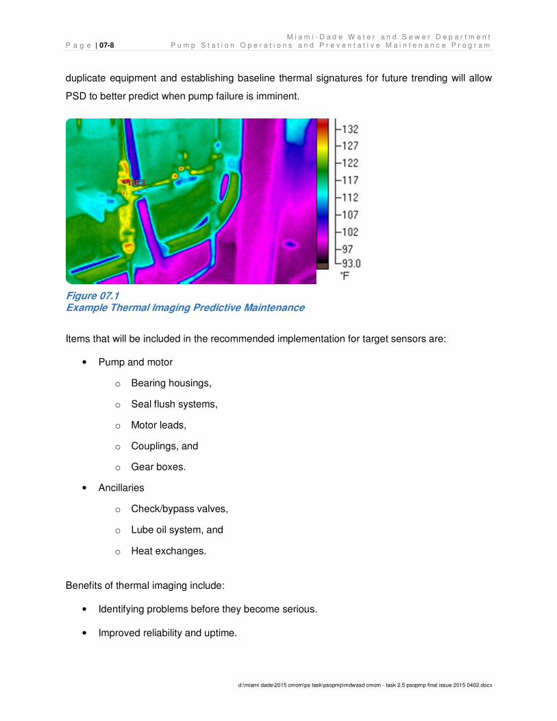
M i a m i - D a d e W a t e r a n d S e w e r D e p a r t m e n t P a g e | 07-8 P u m p S t a t i o n O p e r a t i o n s a n d P r e v e n t a t i v e M a i n t e n a n c e P r o g r a m
d:\miami dade\2015 cmom\ps task\psopmp\mdwasd cmom - task 2.5 psopmp final issue 2015 0402.docx
duplicate equipment and establishing baseline thermal signatures for future trending will allow
PSD to better predict when pump failure is imminent.
Figure 07.1 Example Thermal Imaging Predictive Maintenance
Items that will be included in the recommended implementation for target sensors are:
• Pump and motor
o Bearing housings,
o Seal flush systems,
o Motor leads,
o Couplings, and
o Gear boxes.
• Ancillaries
o Check/bypass valves,
o Lube oil system, and
o Heat exchanges.
Benefits of thermal imaging include:
• Identifying problems before they become serious.
• Improved reliability and uptime.
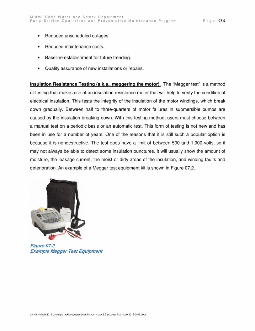
M i a m i - D a d e W a t e r a n d S e w e r D e p a r t m e n t P u m p S t a t i o n O p e r a t i o n s a n d P r e v e n t a t i v e M a i n t e n a n c e P r o g r a m P a g e | 07-9
d:\miami dade\2015 cmom\ps task\psopmp\mdwasd cmom - task 2.5 psopmp final issue 2015 0402.docx
• Reduced unscheduled outages.
• Reduced maintenance costs.
• Baseline establishment for future trending.
• Quality assurance of new installations or repairs.
Insulation Resistance Testing (a.k.a., meggering the motor). The “Megger test” is a method
of testing that makes use of an insulation resistance meter that will help to verify the condition of
electrical insulation. This tests the integrity of the insulation of the motor windings, which break
down gradually. Between half to three-quarters of motor failures in submersible pumps are
caused by the insulation breaking down. With this testing method, users must choose between
a manual test on a periodic basis or an automatic test. This form of testing is not new and has
been in use for a number of years. One of the reasons that it is still such a popular option is
because it is nondestructive. The test does have a limit of between 500 and 1,000 volts, so it
may not always be able to detect some insulation punctures. It will usually show the amount of
moisture, the leakage current, the moist or dirty areas of the insulation, and winding faults and
deterioration. An example of a Megger test equipment kit is shown in Figure 07.2.
Figure 07.2 Example Megger Test Equipment
M i a m i - D a d e W a t e r a n d S e w e r D e p a r t m e n t P a g e | 07-10 P u m p S t a t i o n O p e r a t i o n s a n d P r e v e n t a t i v e M a i n t e n a n c e P r o g r a m
d:\miami dade\2015 cmom\ps task\psopmp\mdwasd cmom - task 2.5 psopmp final issue 2015 0402.docx
Oil Testing. Mechanical issues such as pump cavitation and vibration may be associated with
poor lubrication. By checking the oil for viscosity, levels, temperature, contamination and type,
pump problems may be prevented. Best practice activities to prevent oil-related failures include:
• Monitoring pumps and drivers closely to recognize subtle changes in oil levels, color,
foaming, and cleanliness.
• Using infrared thermometers to check bearing and oil temperatures and inlet and outlet
temps on oil coolers to determine efficiency.
• Frequently draining small amounts of oil from bearing housings to inspect for particle
ingression, wear debris, and water content.
• Noting changes in vibration, unusual sounds, or oil leaks.
• Being vigilant in contamination-control practices. (It can cost 10 times as much to
remove particle contamination from oil as it does to prevent contamination in the first
place.)
• Learning the proper use of desiccant breathers, filter carts, and vacuum dehydrators.
Preventative and Predictive Maintenance Schedules 07.02
Figure 7.3 illustrates the PSD’s process flow chart for issuing routine and preventative
maintenance work orders.
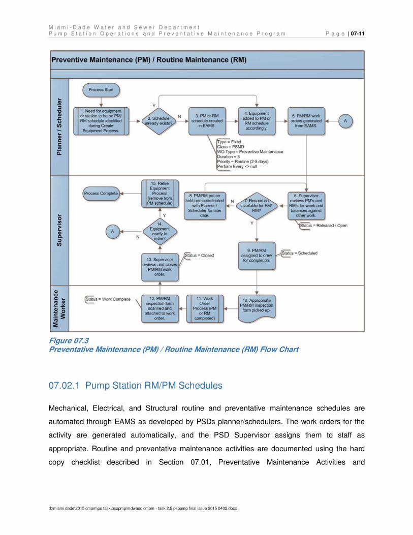
M i a m i - D a d e W a t e r a n d S e w e r D e p a r t m e n t P u m p S t a t i o n O p e r a t i o n s a n d P r e v e n t a t i v e M a i n t e n a n c e P r o g r a m P a g e | 07-11
d:\miami dade\2015 cmom\ps task\psopmp\mdwasd cmom - task 2.5 psopmp final issue 2015 0402.docx
Figure 07.3 Preventative Maintenance (PM) / Routine Maintenance (RM) Flow Chart
07.02.1 Pump Station RM/PM Schedules
Mechanical, Electrical, and Structural routine and preventative maintenance schedules are
automated through EAMS as developed by PSDs planner/schedulers. The work orders for the
activity are generated automatically, and the PSD Supervisor assigns them to staff as
appropriate. Routine and preventative maintenance activities are documented using the hard
copy checklist described in Section 07.01, Preventative Maintenance Activities and
M i a m i - D a d e W a t e r a n d S e w e r D e p a r t m e n t P a g e | 07-12 P u m p S t a t i o n O p e r a t i o n s a n d P r e v e n t a t i v e M a i n t e n a n c e P r o g r a m
d:\miami dade\2015 cmom\ps task\psopmp\mdwasd cmom - task 2.5 psopmp final issue 2015 0402.docx
Responsibilities. Once the work is complete a scanned copy of the checklist is attached to the
work order in EAMS and the work order is closed.
Routine maintenance is conducted:
• Every 28 days by all trades for booster, regional, and priority stations.
• Every 56 days by the Mechanical and Electrical trades for all stations.
• Every 84 days by the Structural trade for all stations
Preventative maintenance is conducted:
• Every year by all trades for booster, regional and proprietary stations (Proprietary
stations are those operated and maintained by the PSD under maintenance contracts.)
• Every 2 years by the Mechanical and Electrical trades for all stations.
• As needed (As determined by the respective supervisor of a service area as a result of
findings during routine maintenance. At any time the supervisor can request required
scheduled maintenance based on field findings).
During the implementation phase of the program, PSD intends to increase efficiency of the work
order process by modifying the business process and implementing a mobile solution within
EAMS that will allow the field crews to create, access, utilize checklists, and populate routine
and preventative maintenance documentation from a hand held device.
07.02.2 Monitoring Systems RM/PM Schedules
As with the pump station maintenance work orders, the SCADA Section maintenance work
orders are processed through EAMS and are scheduled monthly for the regional and booster
pump stations, as well as the rain gauges, and every two years for the remaining submersible
and wet well/dry well pump stations. The work orders are generated by staff, and the supervisor
assigns them to resources as appropriate. SCADA routine and preventative maintenance is
managed on a digital hand held device that provides a checklist for the maintenance team to
follow for calibration and taking down readings. It allows the crew to pull up and check off task
M i a m i - D a d e W a t e r a n d S e w e r D e p a r t m e n t P u m p S t a t i o n O p e r a t i o n s a n d P r e v e n t a t i v e M a i n t e n a n c e P r o g r a m P a g e | 07-13
d:\miami dade\2015 cmom\ps task\psopmp\mdwasd cmom - task 2.5 psopmp final issue 2015 0402.docx
items as they are done. Since it is linked to EAMS, once the work is completed the work order is
closed.
The SCADA Section performs preventative maintenance monthly or bi-annually, depending on
staff-generated work orders in EAMS. See the SCADA preventative maintenance procedures
provided in Appendix E, SCADA Maintenance Task List. The task lists in Appendix E were
generated in EAMS. The following items are included:
• Utility Power Failure Alarm,
• Pump Failure Alarm,
• Pump Run Time Data Logging,
• Pump Duty Cycle Data Logging,
• Pump On/Off Status & Logging,
• Water Pressure & Flow,
• Wet Well Level with High/Low Alarm,
• Pump Warnings, Faults & Alarms Generator Status & Alarms, and
• Generator Status & Alarms.
The SCADA Section Preventative Maintenance Work Orders include Inspection Points. In
EAMS, Inspection Points were created for each discrete task that the user would need to
execute for each piece of equipment. Inspections Points are set up as either quantitative
(requiring a numerical input), qualitative (requiring a text input either from a list of values or free
text), or meter reading (numerical entry that is passed to a Meter in EAMS). The execution of
Preventative Maintenance Work Orders in the field is further facilitated by the use of the Infor
Advanced Mobile solution which, once a user synchs their work from the EAMS database to the
device, provides disconnected access to the EAMS solution and store-and-forward technology
that allows the device to synch up with the EAMS database when connectivity exists.
M i a m i - D a d e W a t e r a n d S e w e r D e p a r t m e n t P a g e | 07-14 P u m p S t a t i o n O p e r a t i o n s a n d P r e v e n t a t i v e M a i n t e n a n c e P r o g r a m
d:\miami dade\2015 cmom\ps task\psopmp\mdwasd cmom - task 2.5 psopmp final issue 2015 0402.docx
Monthly Work Order Status Reports 07.03
The PSD opens and closes work orders when the work is completed. Monthly EAMS reports are
generated indicating the number of open work orders each month. To demonstrate the
timeliness of the work order opening and closing processes an example listing of work orders
within the EAMS system based on a monthly filter is included in Appendix F, Work Order Status
Report EAMS Screen Shot Examples.
M i a m i - D a d e W a t e r a n d S e w e r D e p a r t m e n t P u m p S t a t i o n O p e r a t i o n s a n d P r e v e n t a t i v e M a i n t e n a n c e P r o g r a m P a g e | 08-1
d:\miami dade\2015 cmom\ps task\psopmp\mdwasd cmom - task 2.5 psopmp final issue 2015 0402.docx
Inventory Management System 08.
MDWASD’s inventory management system provides a record of resources including parts,
equipment, and facilities to support the field operations and maintenance activities that are
conducted by the PSD.
Spare Part Locations 08.01
Workshops for each of the PSD’s four sections are located at the Westwood Lakes, 36th Street,
and South Miami Heights Maintenance Yards, and at the North District WWTP. The Westwood
Lakes facility is strategically located near the center of all the service areas and is the facility
recommended to house the pump station’s SCADA monitoring and control center. The
Westwood Lakes facility was built exclusively for pump station operations, but MDWASD now
uses the workshop for other divisions and groups.
Pump station spare parts are stored in facilities in various locations through the four service
areas so the parts are accessible quickly by the maintenance crews without extensive urban
driving. There are a total of eight MDWASD Inventory Storerooms.
• Medley Yard Storeroom (7301 NW 70th Street, Miami, FL 33166),
• Hialeah Storeroom (1100 West 2nd Avenue, Hialeah, FL 33010),
• Alexander Orr Storeroom (6800 SW 87thy Avenue, Miami, FL 33173),
• Westwood Lakes Storeroom (4801 SW 117th Avenue, Miami, FL 33175),
• Water Transmission and Distribution Storeroom (1001 NW 11th Street, Miami, FL
33136),
• Virginia Key (Central District WWTP) Storeroom (3900 Rickenbacker Causeway, Key
Biscayne, FL 33190),
• Interama (North District WWTP) Storeroom (2575 NE 156th Street, Miami, FL 33160),
and
• Blackpoint (South District WWTP) Storeroom (8950 SW 232nd Street, Miami, FL 33190).
M i a m i - D a d e W a t e r a n d S e w e r D e p a r t m e n t P a g e | 08-2 P u m p S t a t i o n O p e r a t i o n s a n d P r e v e n t a t i v e M a i n t e n a n c e P r o g r a m
d:\miami dade\2015 cmom\ps task\psopmp\mdwasd cmom - task 2.5 psopmp final issue 2015 0402.docx
Critical Parts and Equipment Locations 08.02
Parts requiring continuous and immediate availability to support emergency repairs are defined
as critical parts. The equipment required to successfully perform emergency repairs is defined
as critical equipment. Examples of critical equipment include: pumps for bypass, hoses,
generators, portable lights; small tools required to install critical parts; pump station system
Asset Maps; etc. A list of spare parts and equipment indicated as “insurance items” is provided
in Appendix G, Critical Spare Parts and Equipment List.
Inventory Management 08.03
Purchasing is centralized for stock items and decentralized for divisional purchases. An informal
procurement process exists for equipment and repair services equaling $500,000 or less using
multiple source quotations. For items above this amount, the solicitation has to be routed to the
County Department of Procurement Management. Procurement Management reviews the
solicitation process and the approval goes before the Board of County Commissioners.
Emergency purchase orders can also be issued to override the normal, lengthy process when a
documented emergency arises.
MDWASD’s Stores and Procurement Division uses EAMS to inventory and track stored parts for
pump stations and to track location as well as inventory of specific items. The Stores and
Procurement Division staff handle stock, storeroom management, and procurement of outside
contracts for spare parts, materials, and services. The Stores and Procurement Division tracks
inventory through the use of Division and Inventory Stores. Division (“D”) Stores were created
for local tracking within a department. Tracking is determined by division and trade. Inventory
(“I”) Stores manage inventory across departments and are not owned by any one department.
EAMS allows for the tracking of stored parts for pump stations and track location as well as
inventory of specific items. Items in the Stores and Procurement Division’s system identified as
“Insurance Items” are parts and equipment that must be maintained at or above the minimum
levels either due to availability or importance.
M i a m i - D a d e W a t e r a n d S e w e r D e p a r t m e n t P u m p S t a t i o n O p e r a t i o n s a n d P r e v e n t a t i v e M a i n t e n a n c e P r o g r a m P a g e | 08-3
d:\miami dade\2015 cmom\ps task\psopmp\mdwasd cmom - task 2.5 psopmp final issue 2015 0402.docx
Primary spare parts inventories are maintained in the Stores and Procurement Division store
rooms. As a best practice, MDWASD maintains local annual contracts to supply larger
quantities of pump station-related parts and equipment.
Upon full implementation of program recommendations, spare parts will be checked out of the
inventory using a bar coding system and the EAMS system tracks the transaction, the quantity
in stock, and the location of the parts. Currently, the Stores and Procurement Division adjusts
buying and stocking of inventory based on historical use tracked in the EAMS system.
Restocking decisions are made on a max/min system. Stores and Procurement manages a list
of County contracts of multiple manufacturers necessary to supply “Insurance Items” and other
spare parts that are necessary to manage the WCTS. MDWASD is the largest user of these
contracts for their system operations and maintenance. These contracts have caps and if
exceeded approval is required from the Board of County Commissioners.
Four of the warehouse locations have vehicle maintenance facilities to service vehicles and
equipment. The four vehicle maintenance facilities are at Westwood Lakes, Water Transmission
and Distribution (11th Street), Virginia Key (Central District WWTP), and Blackpoint (South
District WWTP).
Procedures for Updating List 08.04
During implementation, procedures for maintenance of an accurate inventory through the EAMS
asset inventory will assist in ensuring the availability of critical spare parts for the pump stations.
Should an unexpected need arise for a particular spare part or piece of equipment arise,
MDWASD has contracts with virtually every manufacturer currently being used to ensure timely
delivery of the needed item. If a manufacturer is not on the contract, they are added proactively
so parts can be ordered in a timely manner.

M i a m i - D a d e W a t e r a n d S e w e r D e p a r t m e n t P a g e | 08-4 P u m p S t a t i o n O p e r a t i o n s a n d P r e v e n t a t i v e M a i n t e n a n c e P r o g r a m
d:\miami dade\2015 cmom\ps task\psopmp\mdwasd cmom - task 2.5 psopmp final issue 2015 0402.docx
THIS PAGE LEFT INTENTIONALLY BLANK
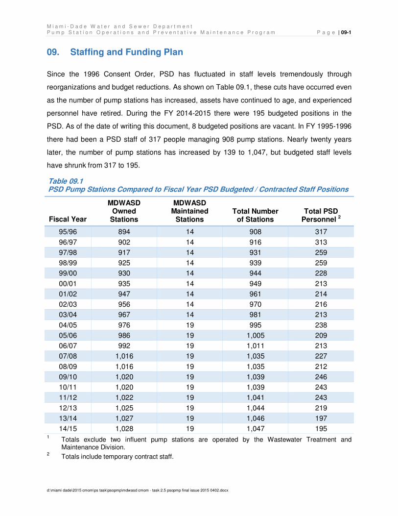
M i a m i - D a d e W a t e r a n d S e w e r D e p a r t m e n t P u m p S t a t i o n O p e r a t i o n s a n d P r e v e n t a t i v e M a i n t e n a n c e P r o g r a m P a g e | 09-1
d:\miami dade\2015 cmom\ps task\psopmp\mdwasd cmom - task 2.5 psopmp final issue 2015 0402.docx
Staffing and Funding Plan 09.
Since the 1996 Consent Order, PSD has fluctuated in staff levels tremendously through
reorganizations and budget reductions. As shown on Table 09.1, these cuts have occurred even
as the number of pump stations has increased, assets have continued to age, and experienced
personnel have retired. During the FY 2014-2015 there were 195 budgeted positions in the
PSD. As of the date of writing this document, 8 budgeted positions are vacant. In FY 1995-1996
there had been a PSD staff of 317 people managing 908 pump stations. Nearly twenty years
later, the number of pump stations has increased by 139 to 1,047, but budgeted staff levels
have shrunk from 317 to 195.
Table 09.1 PSD Pump Stations Compared to Fiscal Year PSD Budgeted / Contracted Staff Positions
Fiscal Year
MDWASD Owned
Stations
MDWASD Maintained
Stations Total Number
of Stations Total PSD
Personnel 2
95/96 894 14 908 317
96/97 902 14 916 313
97/98 917 14 931 259
98/99 925 14 939 259
99/00 930 14 944 228
00/01 935 14 949 213
01/02 947 14 961 214
02/03 956 14 970 216
03/04 967 14 981 213
04/05 976 19 995 238
05/06 986 19 1,005 209
06/07 992 19 1,011 213
07/08 1,016 19 1,035 227
08/09 1,016 19 1,035 212
09/10 1,020 19 1,039 246
10/11 1,020 19 1,039 243
11/12 1,022 19 1,041 243
12/13 1,025 19 1,044 219
13/14 1,027 19 1,046 197
14/15 1,028 19 1,047 195 1 Totals exclude two influent pump stations are operated by the Wastewater Treatment and
Maintenance Division. 2 Totals include temporary contract staff.

M i a m i - D a d e W a t e r a n d S e w e r D e p a r t m e n t P a g e | 09-2 P u m p S t a t i o n O p e r a t i o n s a n d P r e v e n t a t i v e M a i n t e n a n c e P r o g r a m
d:\miami dade\2015 cmom\ps task\psopmp\mdwasd cmom - task 2.5 psopmp final issue 2015 0402.docx
Staff and Skills Needs 09.01
The PSD continues to face challenges in recruiting qualified staff and providing the necessary
training. The result of deficient staffing includes reduced maintenance, longer intervals between
routine and preventative maintenance schedules, reduced task list, increased overtime, and
increased likelihood of failure. A comprehensive training program for several facets of the
maintenance program is needed to educate staff and provide incentive for them to grow within
the organization. It has become increasingly difficult to recruit quality people mainly due to the
fact that managers have to adhere to hiring protocols and job descriptions which can result in
un-skilled labor entering the organization. Appendix H, Pump Station Division Job List, contains
a listing of current PSD budgeted positions organized by trade.
PSOPMP implementation will include a staff hiring plan and equipment recommendations to
allow PSD to operate at a higher level. Currently, the PSD does not have dedicated night time
or weekend (i.e., second shift) maintenance crews. There are only day crews in each trade,
structural, mechanical, and electrical, that operate during a single day shift. These same crews
are on call for the night and weekend shifts, and are summoned by the Communications Center
whenever an alarm event and/or an emergency arise. Not having second shift crews severely
limits the PSD’s ability to address issues timely in the evenings and on weekends putting
MSWASD at risk for overflow situations.
The following draft staff hiring plan is based on staffing to a 24/7 basis within PSD. The draft
staffing plan is also based on existing asset levels. Growth of the number of pump stations
within the WCTS will require further analysis to determine potential additional staffing needs.
The implementation recommendation includes a budgetary number for training that also needs
to be further studied to get a more accurate picture of the program.
Table 09.2 recommends additional PSD staff augmentation to address existing staffing
shortfalls associated with emergency operations.
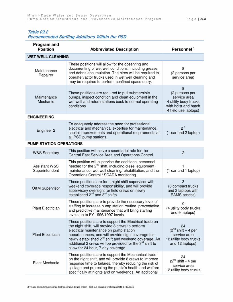
M i a m i - D a d e W a t e r a n d S e w e r D e p a r t m e n t P u m p S t a t i o n O p e r a t i o n s a n d P r e v e n t a t i v e M a i n t e n a n c e P r o g r a m P a g e | 09-3
d:\miami dade\2015 cmom\ps task\psopmp\mdwasd cmom - task 2.5 psopmp final issue 2015 0402.docx
Table 09.2 Recommended Staffing Additions Within the PSD
Program and Position Abbreviated Description Personnel 1
WET WELL CLEANING
Maintenance Repairer
These positions will allow for the observing and documenting of wet well conditions, including grease and debris accumulation. The hires will be required to operate vactor trucks used in wet well cleaning and may be required to perform confined space entry.
8 (2 persons per service area)
Maintenance Mechanic
These positions are required to pull submersible pumps, inspect condition and clean equipment in the wet well and return stations back to normal operating conditions
8 (2 persons per service area
4 utility body trucks with hoist and hatch 4 field use laptops)
ENGINEERING
Engineer 2
To adequately address the need for professional electrical and mechanical expertise for maintenance, capital improvements and operational requirements at all PSD pump stations.
2 1
(1 car and 2 laptop)
PUMP STATION OPERATIONS
W&S Secretary This position will serve a secretarial role for the Central East Service Area and Operations Control.
2
Assistant W&S Superintendent
This position will supervise the additional personnel needed for the 2
nd shift, including diesel equipment
maintenance, wet well cleaning/rehabilitation, and the Operations Control / SCADA monitoring.
1 (1 car and 1 laptop)
O&M Supervisor
These positions are for a night shift supervisor with weekend coverage responsibility, and will provide supervisory oversight for field crews on newly established 2
nd and 3
rd shifts.
3 (3 compact trucks and 3 laptops with
EAMS access)
Plant Electrician
These positions are to provide the necessary level of staffing to increase pump station routine, preventative, and predictive maintenance that will bring staffing levels up to FY 1996/1997 levels.
9 (4 utility body trucks
and 9 laptops)
Plant Electrician
These positions are to support the Electrical trade on the night shift, will provide 8 crews to perform electrical maintenance on pump station appurtenances, and will provide night coverage for newly established 2
nd shift and weekend coverage. An
additional 2 crews will be provided for the 3rd
shift to allow for 24 hour, 7-day coverage.
24 (2
nd shift – 4 per
service area 12 utility body trucks
and 12 laptops)
Plant Mechanic
These positions are to support the Mechanical trade on the night shift, and will provide 8 crews to improve response time to failures, thereby reducing the risk of spillage and protecting the public’s health and welfare specifically at nights and on weekends. An additional
24 (2
nd shift - 4 per
service area 12 utility body trucks
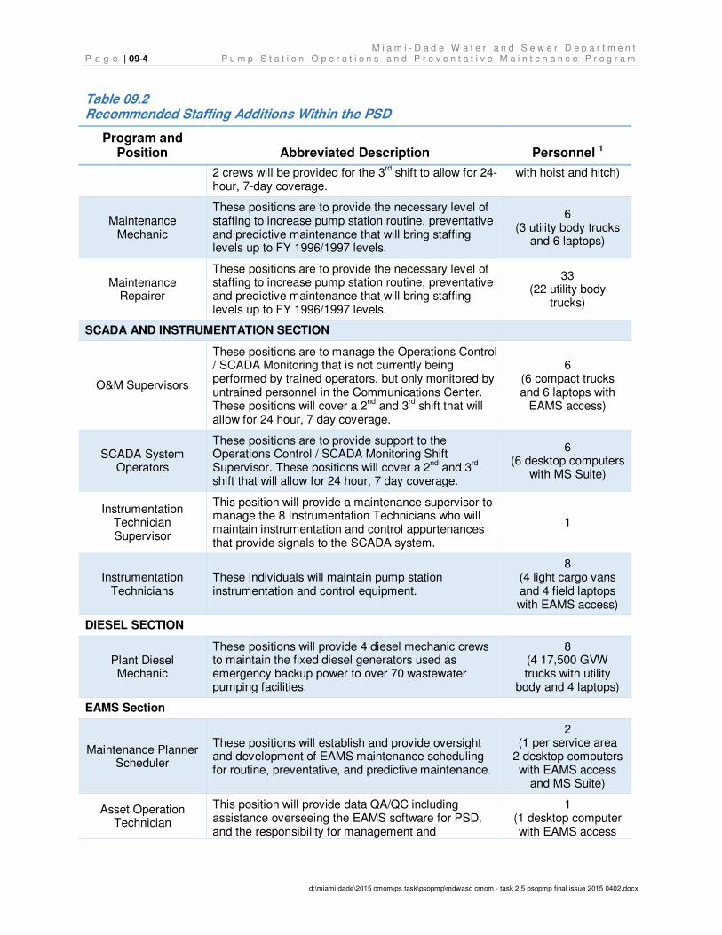
M i a m i - D a d e W a t e r a n d S e w e r D e p a r t m e n t P a g e | 09-4 P u m p S t a t i o n O p e r a t i o n s a n d P r e v e n t a t i v e M a i n t e n a n c e P r o g r a m
d:\miami dade\2015 cmom\ps task\psopmp\mdwasd cmom - task 2.5 psopmp final issue 2015 0402.docx
Table 09.2 Recommended Staffing Additions Within the PSD
Program and Position Abbreviated Description Personnel 1
2 crews will be provided for the 3rd shift to allow for 24-
hour, 7-day coverage. with hoist and hitch)
Maintenance Mechanic
These positions are to provide the necessary level of staffing to increase pump station routine, preventative and predictive maintenance that will bring staffing levels up to FY 1996/1997 levels.
6 (3 utility body trucks
and 6 laptops)
Maintenance Repairer
These positions are to provide the necessary level of staffing to increase pump station routine, preventative and predictive maintenance that will bring staffing levels up to FY 1996/1997 levels.
33 (22 utility body
trucks)
SCADA AND INSTRUMENTATION SECTION
O&M Supervisors
These positions are to manage the Operations Control / SCADA Monitoring that is not currently being performed by trained operators, but only monitored by untrained personnel in the Communications Center. These positions will cover a 2
nd and 3
rd shift that will
allow for 24 hour, 7 day coverage.
6 (6 compact trucks and 6 laptops with
EAMS access)
SCADA System Operators
These positions are to provide support to the Operations Control / SCADA Monitoring Shift Supervisor. These positions will cover a 2
nd and 3
rd
shift that will allow for 24 hour, 7 day coverage.
6 (6 desktop computers
with MS Suite)
Instrumentation Technician Supervisor
This position will provide a maintenance supervisor to manage the 8 Instrumentation Technicians who will maintain instrumentation and control appurtenances that provide signals to the SCADA system.
1
Instrumentation Technicians
These individuals will maintain pump station instrumentation and control equipment.
8 (4 light cargo vans and 4 field laptops with EAMS access)
DIESEL SECTION
Plant Diesel Mechanic
These positions will provide 4 diesel mechanic crews to maintain the fixed diesel generators used as emergency backup power to over 70 wastewater pumping facilities.
8 (4 17,500 GVW trucks with utility
body and 4 laptops)
EAMS Section
Maintenance Planner Scheduler
These positions will establish and provide oversight and development of EAMS maintenance scheduling for routine, preventative, and predictive maintenance.
2 (1 per service area
2 desktop computers with EAMS access
and MS Suite)
Asset Operation Technician
This position will provide data QA/QC including assistance overseeing the EAMS software for PSD, and the responsibility for management and
1 (1 desktop computer with EAMS access
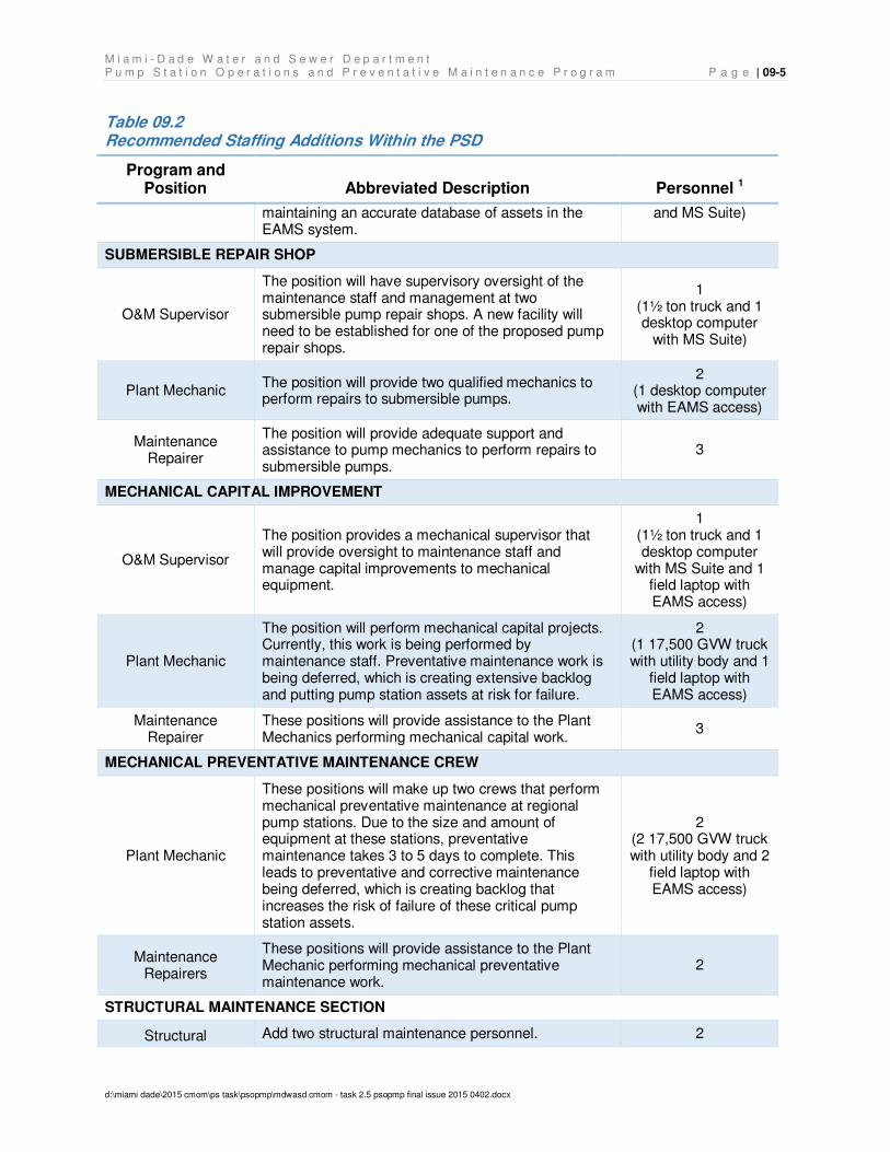
M i a m i - D a d e W a t e r a n d S e w e r D e p a r t m e n t P u m p S t a t i o n O p e r a t i o n s a n d P r e v e n t a t i v e M a i n t e n a n c e P r o g r a m P a g e | 09-5
d:\miami dade\2015 cmom\ps task\psopmp\mdwasd cmom - task 2.5 psopmp final issue 2015 0402.docx
Table 09.2 Recommended Staffing Additions Within the PSD
Program and Position Abbreviated Description Personnel 1
maintaining an accurate database of assets in the EAMS system.
and MS Suite)
SUBMERSIBLE REPAIR SHOP
O&M Supervisor
The position will have supervisory oversight of the maintenance staff and management at two submersible pump repair shops. A new facility will need to be established for one of the proposed pump repair shops.
1 (1½ ton truck and 1 desktop computer
with MS Suite)
Plant Mechanic The position will provide two qualified mechanics to perform repairs to submersible pumps.
2 (1 desktop computer with EAMS access)
Maintenance Repairer
The position will provide adequate support and assistance to pump mechanics to perform repairs to submersible pumps.
3
MECHANICAL CAPITAL IMPROVEMENT
O&M Supervisor
The position provides a mechanical supervisor that will provide oversight to maintenance staff and manage capital improvements to mechanical equipment.
1 (1½ ton truck and 1 desktop computer
with MS Suite and 1 field laptop with EAMS access)
Plant Mechanic
The position will perform mechanical capital projects. Currently, this work is being performed by maintenance staff. Preventative maintenance work is being deferred, which is creating extensive backlog and putting pump station assets at risk for failure.
2 (1 17,500 GVW truck with utility body and 1
field laptop with EAMS access)
Maintenance Repairer
These positions will provide assistance to the Plant Mechanics performing mechanical capital work.
3
MECHANICAL PREVENTATIVE MAINTENANCE CREW
Plant Mechanic
These positions will make up two crews that perform mechanical preventative maintenance at regional pump stations. Due to the size and amount of equipment at these stations, preventative maintenance takes 3 to 5 days to complete. This leads to preventative and corrective maintenance being deferred, which is creating backlog that increases the risk of failure of these critical pump station assets.
2 (2 17,500 GVW truck with utility body and 2
field laptop with EAMS access)
Maintenance Repairers
These positions will provide assistance to the Plant Mechanic performing mechanical preventative maintenance work.
2
STRUCTURAL MAINTENANCE SECTION
Structural Add two structural maintenance personnel. 2
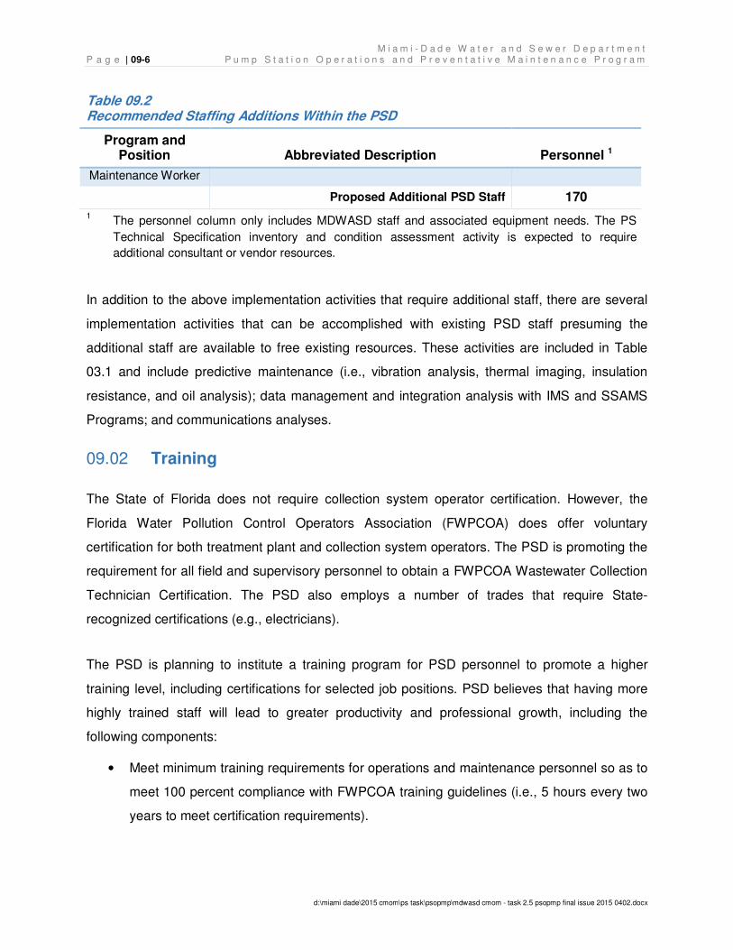
M i a m i - D a d e W a t e r a n d S e w e r D e p a r t m e n t P a g e | 09-6 P u m p S t a t i o n O p e r a t i o n s a n d P r e v e n t a t i v e M a i n t e n a n c e P r o g r a m
d:\miami dade\2015 cmom\ps task\psopmp\mdwasd cmom - task 2.5 psopmp final issue 2015 0402.docx
Table 09.2 Recommended Staffing Additions Within the PSD
Program and Position Abbreviated Description Personnel 1
Maintenance Worker
Proposed Additional PSD Staff 170
1 The personnel column only includes MDWASD staff and associated equipment needs. The PS
Technical Specification inventory and condition assessment activity is expected to require
additional consultant or vendor resources.
In addition to the above implementation activities that require additional staff, there are several
implementation activities that can be accomplished with existing PSD staff presuming the
additional staff are available to free existing resources. These activities are included in Table
03.1 and include predictive maintenance (i.e., vibration analysis, thermal imaging, insulation
resistance, and oil analysis); data management and integration analysis with IMS and SSAMS
Programs; and communications analyses.
Training 09.02
The State of Florida does not require collection system operator certification. However, the
Florida Water Pollution Control Operators Association (FWPCOA) does offer voluntary
certification for both treatment plant and collection system operators. The PSD is promoting the
requirement for all field and supervisory personnel to obtain a FWPCOA Wastewater Collection
Technician Certification. The PSD also employs a number of trades that require State-
recognized certifications (e.g., electricians).
The PSD is planning to institute a training program for PSD personnel to promote a higher
training level, including certifications for selected job positions. PSD believes that having more
highly trained staff will lead to greater productivity and professional growth, including the
following components:
• Meet minimum training requirements for operations and maintenance personnel so as to
meet 100 percent compliance with FWPCOA training guidelines (i.e., 5 hours every two
years to meet certification requirements).
M i a m i - D a d e W a t e r a n d S e w e r D e p a r t m e n t P u m p S t a t i o n O p e r a t i o n s a n d P r e v e n t a t i v e M a i n t e n a n c e P r o g r a m P a g e | 09-7
d:\miami dade\2015 cmom\ps task\psopmp\mdwasd cmom - task 2.5 psopmp final issue 2015 0402.docx
• Meet minimum training requirements for WCTS health and safety issues (e.g., confined
space entry, waterborne pathogens, gas monitoring, lockout/tagout, etc.).
• Encourage meeting higher training levels for operations and maintenance personnel to
meet other state mandatory certification requirements (i.e., North Carolina with 6 hours
every year).
• Recommend more rigorous training for all trades in addition to the FWPCOA
requirements.
• Recommend specialized electrical controls, variable frequency drives, and power
training for electrical personnel.
• Involve cross-training of maintenance personnel to allow mechanical, electrical, and
structural trades to understand each other’s scope of work and to better work together to
achieve common goals.
Funding Needs 09.03
Based on the PSOPMP implementation activities (as listed in Table 03.2), the identified staff
required (as listed in Table 09.2), estimated equipment needed, and the identified consultant or
vendor resources required (as footnoted in Table 09.2), Table 09.3 details the anticipated
funding needs under the phased implementation for additional staffing. The funding shown in
Table 09.2 does not include the funding requirements to perform existing PSD functions. The
baseline of existing funding needs to stay the same as in the FY 2014-2015 budget. The
anticipated budget needs shown in Table 09.3 is based on average salary budget found in
Appendix H, Pump Stations Division Job List. The anticipated budget need details are included
in Appendix I, Anticipated Budget Needs.
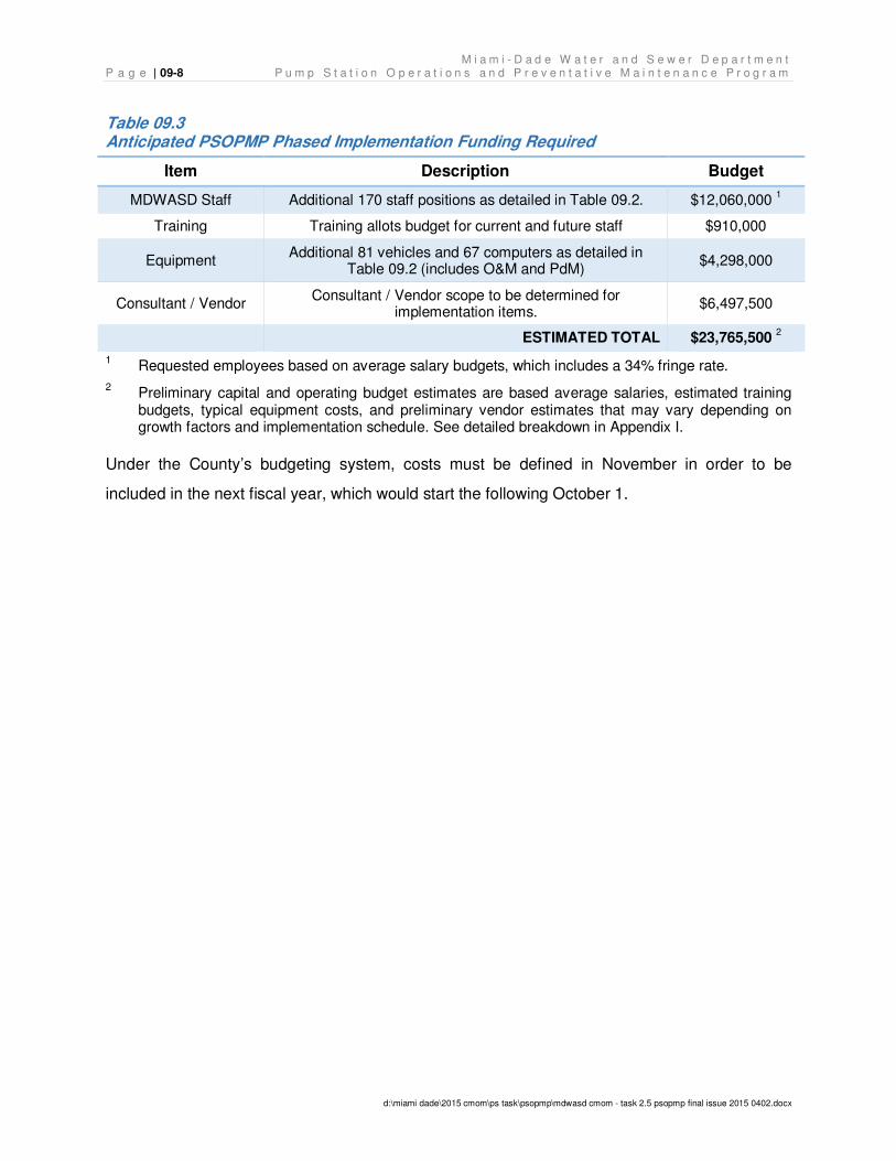
M i a m i - D a d e W a t e r a n d S e w e r D e p a r t m e n t P a g e | 09-8 P u m p S t a t i o n O p e r a t i o n s a n d P r e v e n t a t i v e M a i n t e n a n c e P r o g r a m
d:\miami dade\2015 cmom\ps task\psopmp\mdwasd cmom - task 2.5 psopmp final issue 2015 0402.docx
Table 09.3 Anticipated PSOPMP Phased Implementation Funding Required
Item Description Budget
MDWASD Staff Additional 170 staff positions as detailed in Table 09.2. $12,060,000 1
Training Training allots budget for current and future staff $910,000
Equipment Additional 81 vehicles and 67 computers as detailed in
Table 09.2 (includes O&M and PdM) $4,298,000
Consultant / Vendor Consultant / Vendor scope to be determined for
implementation items. $6,497,500
ESTIMATED TOTAL $23,765,500 2
1 Requested employees based on average salary budgets, which includes a 34% fringe rate.
2 Preliminary capital and operating budget estimates are based average salaries, estimated training budgets, typical equipment costs, and preliminary vendor estimates that may vary depending on growth factors and implementation schedule. See detailed breakdown in Appendix I.
Under the County’s budgeting system, costs must be defined in November in order to be
included in the next fiscal year, which would start the following October 1.
M i a m i - D a d e W a t e r a n d S e w e r D e p a r t m e n t P u m p S t a t i o n O p e r a t i o n s a n d P r e v e n t a t i v e M a i n t e n a n c e P r o g r a m P a g e | 10-1
D:\Miami Dade\2015 CMOM\PS Task\PSOPMP\MDWASD CMOM - Task 2.5 PSOPMP final issue 2015 0402.docx
Climate Change Impacts 10.
In May 2014, the Miami-Dade County Board of County Commissioners passed a Resolution
requiring that all County infrastructure projects “shall consider” the potential impacts of sea level
rise and storm surge during all project phases (including planning, design, and construction) to
ensure that these projects will function properly for fifty years or the design life of the project,
whichever is greater. The County has also requested consideration of other climate change
implications for County infrastructure projects.
This section addresses climate change impacts for the pump stations operated and maintained
by PSD.
Pump Station Vulnerability to Climate Change 10.01
As the evaluation progresses with more specific recommendations for the pump station
requirements each of the required CMOM Program shall take into consideration the vulnerability
of the facilities to climate change impacts, such as sea level rise, storm surge, wind, and
flooding, and the necessary improvements that can be made in pump station O&M protocols.
For example, elevated groundwater levels from sea level rise and changes to infiltration are
likely to increase pump operating times due to the expected increase in extraneous water
entering the sewer system. This, and other climate changes, such as prolonged storms, will
have impacts to the recommendations for the monitoring system and response protocols,
technical specifications, preventative O&M schedules, and equipment inventories.
As a signatory to the South Florida Regional Climate Change Compact (SFRCCC), Miami-Dade
joined other south Florida counties to develop a coordinated strategy for dealing with impacts of
climate change. This includes a unified planning estimate for sea level rise projections. In 2012,
the SFRCCC released the report, Analysis of the Vulnerability of Southeast Florida to Sea Level
Rise, which contained planning time horizons and potential changes to sea level. This report
predicted up to 3 feet of sea level rise by 2075. This report built on the SFRCCC
recommendations previously related in the 2011 report, A Unified Sea Level Rise Project for
Southeast Florida, where recommendations from the U.S. Army Corps of Engineers (USACE)
were reviewed for projections to 2030 and 2060.
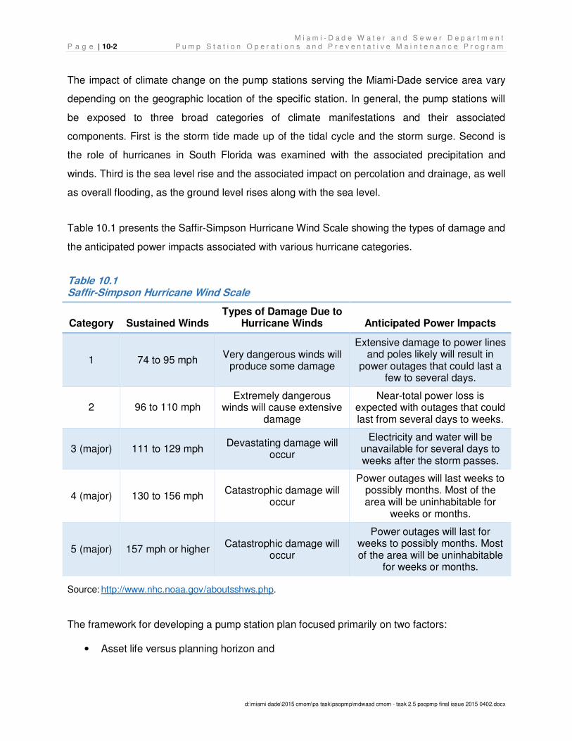
M i a m i - D a d e W a t e r a n d S e w e r D e p a r t m e n t P a g e | 10-2 P u m p S t a t i o n O p e r a t i o n s a n d P r e v e n t a t i v e M a i n t e n a n c e P r o g r a m
d:\miami dade\2015 cmom\ps task\psopmp\mdwasd cmom - task 2.5 psopmp final issue 2015 0402.docx
The impact of climate change on the pump stations serving the Miami-Dade service area vary
depending on the geographic location of the specific station. In general, the pump stations will
be exposed to three broad categories of climate manifestations and their associated
components. First is the storm tide made up of the tidal cycle and the storm surge. Second is
the role of hurricanes in South Florida was examined with the associated precipitation and
winds. Third is the sea level rise and the associated impact on percolation and drainage, as well
as overall flooding, as the ground level rises along with the sea level.
Table 10.1 presents the Saffir-Simpson Hurricane Wind Scale showing the types of damage and
the anticipated power impacts associated with various hurricane categories.
Table 10.1 Saffir-Simpson Hurricane Wind Scale
Category Sustained Winds Types of Damage Due to
Hurricane Winds Anticipated Power Impacts
1 74 to 95 mph Very dangerous winds will
produce some damage
Extensive damage to power lines and poles likely will result in
power outages that could last a few to several days.
2 96 to 110 mph Extremely dangerous
winds will cause extensive damage
Near-total power loss is expected with outages that could last from several days to weeks.
3 (major) 111 to 129 mph Devastating damage will
occur
Electricity and water will be unavailable for several days to weeks after the storm passes.
4 (major) 130 to 156 mph Catastrophic damage will
occur
Power outages will last weeks to possibly months. Most of the area will be uninhabitable for
weeks or months.
5 (major) 157 mph or higher Catastrophic damage will
occur
Power outages will last for weeks to possibly months. Most of the area will be uninhabitable
for weeks or months.
Source: http://www.nhc.noaa.gov/aboutsshws.php.
The framework for developing a pump station plan focused primarily on two factors:
• Asset life versus planning horizon and
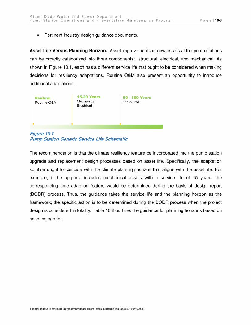
M i a m i - D a d e W a t e r a n d S e w e r D e p a r t m e n t P u m p S t a t i o n O p e r a t i o n s a n d P r e v e n t a t i v e M a i n t e n a n c e P r o g r a m P a g e | 10-3
d:\miami dade\2015 cmom\ps task\psopmp\mdwasd cmom - task 2.5 psopmp final issue 2015 0402.docx
• Pertinent industry design guidance documents.
Asset Life Versus Planning Horizon. Asset improvements or new assets at the pump stations
can be broadly categorized into three components: structural, electrical, and mechanical. As
shown in Figure 10.1, each has a different service life that ought to be considered when making
decisions for resiliency adaptations. Routine O&M also present an opportunity to introduce
additional adaptations.
Figure 10.1 Pump Station Generic Service Life Schematic
The recommendation is that the climate resiliency feature be incorporated into the pump station
upgrade and replacement design processes based on asset life. Specifically, the adaptation
solution ought to coincide with the climate planning horizon that aligns with the asset life. For
example, if the upgrade includes mechanical assets with a service life of 15 years, the
corresponding time adaption feature would be determined during the basis of design report
(BODR) process. Thus, the guidance takes the service life and the planning horizon as the
framework; the specific action is to be determined during the BODR process when the project
design is considered in totality. Table 10.2 outlines the guidance for planning horizons based on
asset categories.
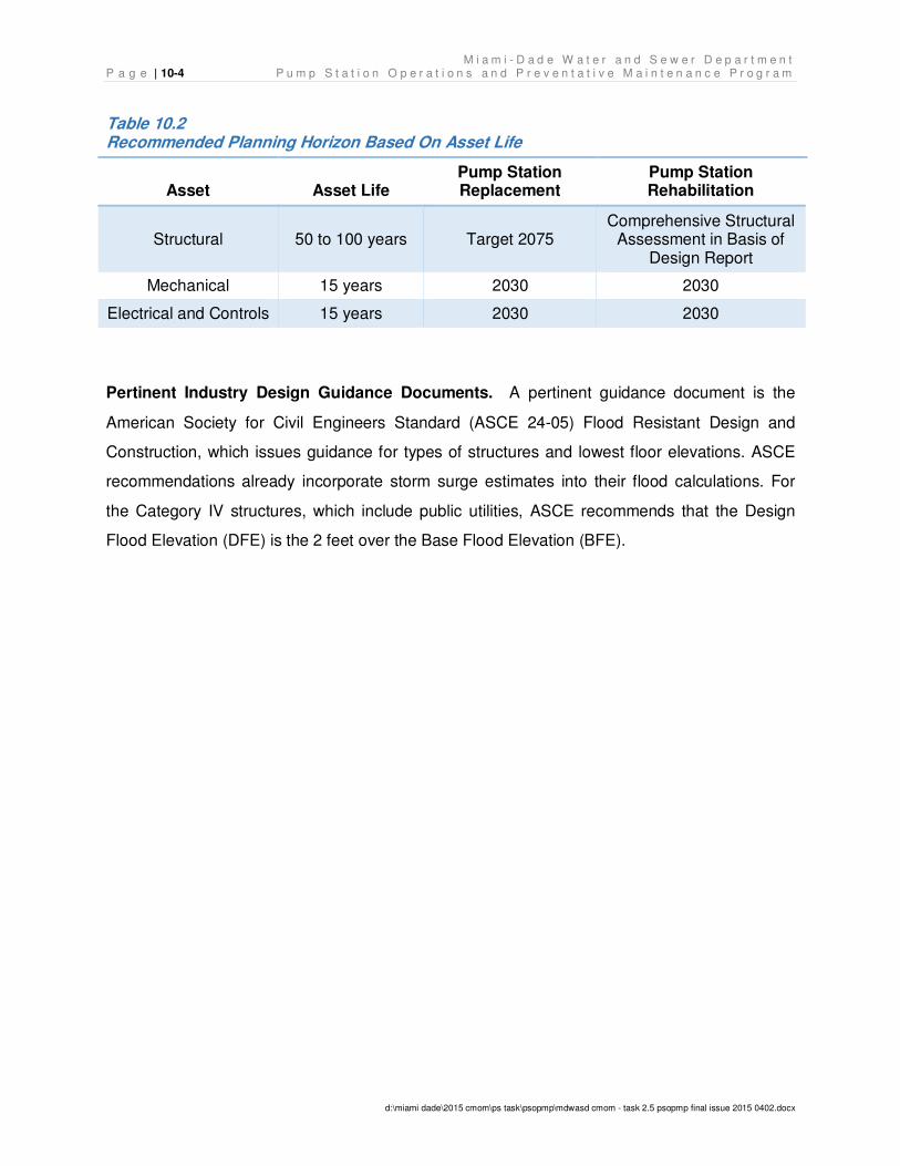
M i a m i - D a d e W a t e r a n d S e w e r D e p a r t m e n t P a g e | 10-4 P u m p S t a t i o n O p e r a t i o n s a n d P r e v e n t a t i v e M a i n t e n a n c e P r o g r a m
d:\miami dade\2015 cmom\ps task\psopmp\mdwasd cmom - task 2.5 psopmp final issue 2015 0402.docx
Table 10.2 Recommended Planning Horizon Based On Asset Life
Asset Asset Life Pump Station Replacement
Pump Station Rehabilitation
Structural 50 to 100 years Target 2075 Comprehensive Structural
Assessment in Basis of Design Report
Mechanical 15 years 2030 2030
Electrical and Controls 15 years 2030 2030
Pertinent Industry Design Guidance Documents. A pertinent guidance document is the
American Society for Civil Engineers Standard (ASCE 24-05) Flood Resistant Design and
Construction, which issues guidance for types of structures and lowest floor elevations. ASCE
recommendations already incorporate storm surge estimates into their flood calculations. For
the Category IV structures, which include public utilities, ASCE recommends that the Design
Flood Elevation (DFE) is the 2 feet over the Base Flood Elevation (BFE).
Appendices 11.
Appendix A: Pump Station Route Flow Schematic by Treatment Plant Service Area
Appendix B: EAMS Pump Station Database
Appendix C: Routine and Preventative Maintenance Task Lists for the Trades
Appendix D: Pump Station Meter Inventory
Appendix E: SCADA Maintenance Task List
Appendix F: Work Order Status Report EAMS Screen Shot Examples
Appendix G: Critical Spare Parts and Equipment List
Appendix H: Pump Station Division Job List
Appendix I: Anticipated Budget Needs

THIS PAGE LEFT INTENTIONALLY BLANK
APPENDIX A
Pump Station Route Flow Schematic by Treatment Plant Service Area

THIS PAGE LEFT INTENTIONALLY BLANK
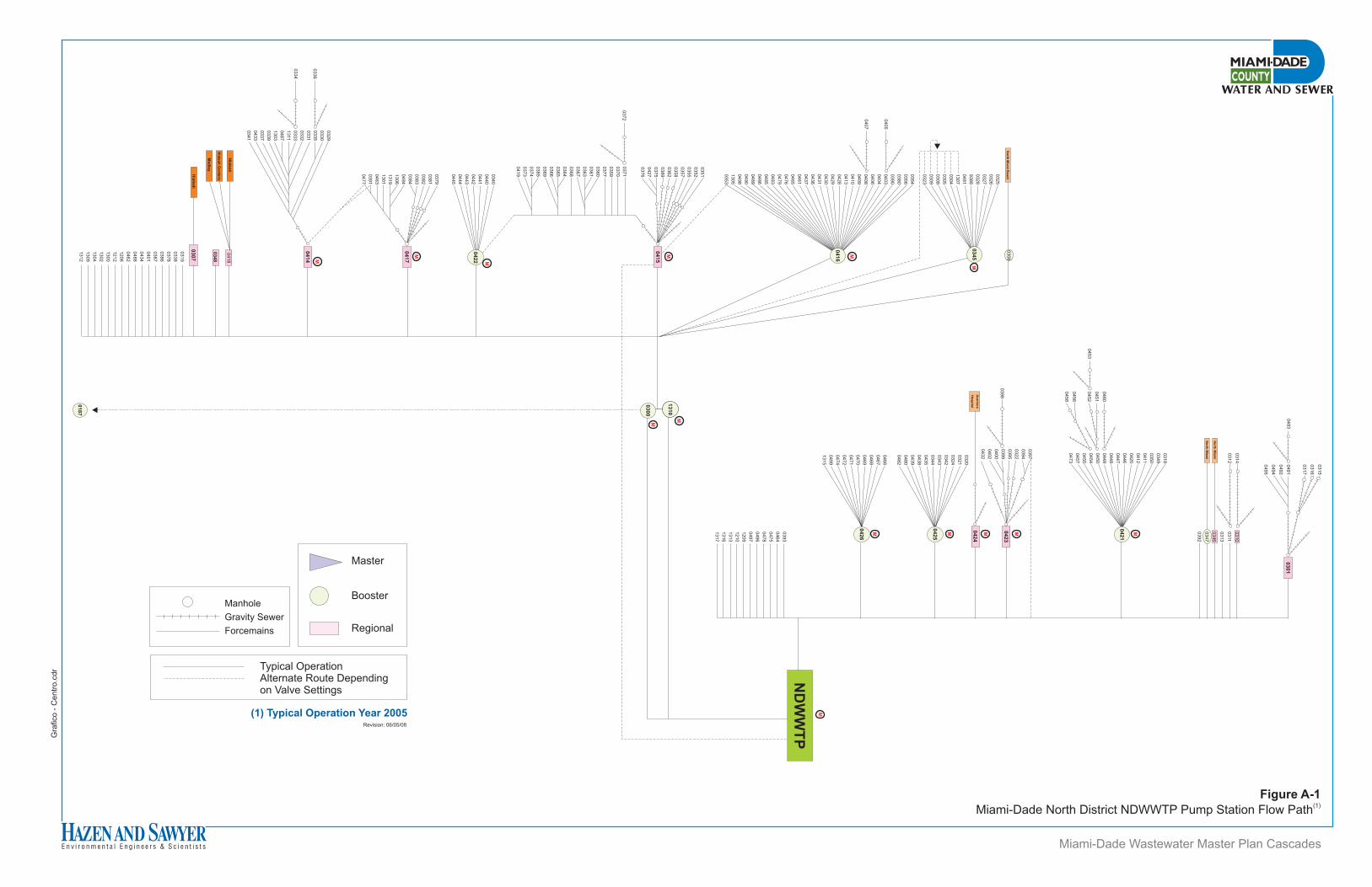
Gra
fico -
Centr
o.c
dr
Miami-Dade Wastewater Master Plan Cascades
0310
0311
0313
0346
0347
0392
0491
0492
0494
0495
0314
0312
No
rth M
iam
i
No
rth M
iam
i
0318
0349
0350
0411
0412
0420
0446
0447
0448
0449
0450
0454
0455
0457
0473
0460
0451
0452
0456
0458
03
01
04
21
M
0320
0321
0324
0342
0343
0344
0435
0438
0439
0480
0482
0466
0467
0468
0469
0470
0471
0472
0474
0499
1315
0398
0393
0464
0475
0478
0496
0497
1209
1210
1313
1316
1317
04
23
ND
WW
TP
04
24
04
25
04
26
13
10
M M M M
0493
No
rth M
iam
i Beach
0306
13
10
0300
M
0453
M
Aven
tura
Ho
sp
ital
M
M0
34
5
0187
0354
0356
0380
0390
0403
0404
0406
0408
0409
0410
0413
0428
0429
0430
0431
0436
0437
0461
0465
0476
0479
0483
0485
0486
0489
0490
0498
1305
0353
M
04
16
0351
0352
0355
0357
0358
0362
0389
0375
0427
0376
M
04
15
0325
0326
0327
0328
9388
0481
1307
0304
0305
0308
0309
0323
0405
0407
0315
0316
0317
0397
0394
0322
0395
0399
0400
0402
0432
Hia
lea
h
0307
0319
0338
0378
0386
0387
0401
0434
0488
0462
1206
1212
1300
1302
1304
1309
1312
Hia
lea
h
0418
Hia
leah
Gard
en
s
Me
dle
y
03
48 M
04
14
0379
0381
0382
0383
0384
0484
1306
1319
1301
0463
0391
0477
M
04
17
0340
0440
0441
0442
0443
0444
0445
M
04
22
0329
0330
0335
0331
0332
0333
1311
0487
1303
0339
0337
0433
0341
0336
0334
0371
0370
0359
0377
0360
0361
0363
0367
0368
0364
0365
0366
0369
0385
0374
0373
0419
0372
Figure A-1(1)
Miami-Dade North District NDWWTP Pump Station Flow Path
Master
Booster
Regional
Typical OperationAlternate Route Dependingon Valve Settings
Manhole
Gravity Sewer
Forcemains
Revision: 06/05/08
(1) Typical Operation Year 2005
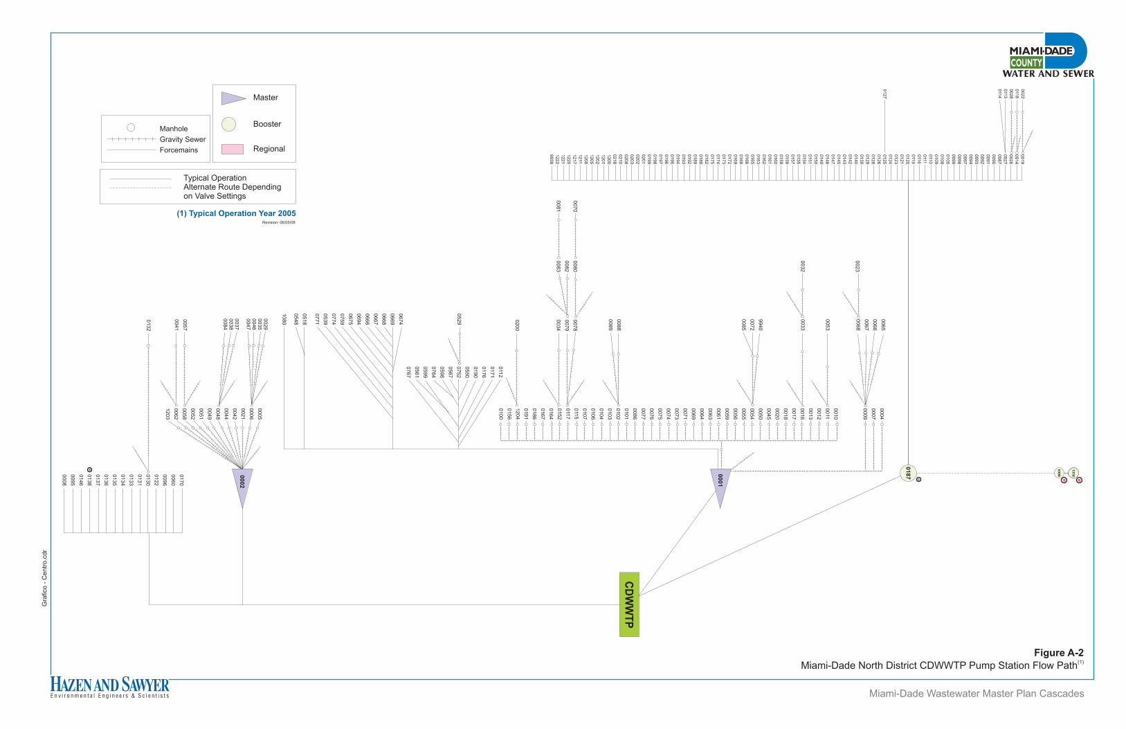
Figure A-2(1)
Miami-Dade North District CDWWTP Pump Station Flow Path
Gra
fico -
Centr
o.c
dr
0010
0011
0012
0013
0016
0017
0018
0020
0045
0050
0054
0055
0056
0059
0061
0063
0064
0069
0071
0073
0074
0075
0076
0077
0086
0101
0102
0103
0104
0106
0107
0115
0117
0152
0164
0167
0186
0191
1204
0156
0100
9940
0072
0085
0004
0007
0009
0065
0066
0067
0068
0033
0187
M
CD
WW
TP
0053
0032
0088
0089
0170
0060
0096
0122
0130
0131
0133
0134
0135
0136
0137
0138
0146
0095
0008
0005
0006
0021
0042
0044
0048
0049
0051
0052
0058
0062
1203
0132
0029
0035
0046
0047
0037
0038
0084
0057
0041
M
00
02
0019
0014
0026
0027
0087
0090
0091
0092
0093
0094
0097
0098
0099
0105
0108
0109
0110
0111
0116
0119
0120
0121
0123
0124
0125
0126
0128
0129
0139
0140
0142
0143
0145
0147
0148
0149
0150
0151
0154
0155
0157
0158
0159
0160
0161
0162
0163
0165
0166
0168
0169
0172
0173
0174
0175
0182
0188
0189
0192
0193
0194
0195
0196
0197
0198
0199
0201
0202
0203
0208
0210
0218
1200
1201
1202
1205
1208
1211
1217
1220
1221
1222
9938
0022
0118
0028
0113
0114
0127
0023
0200
00
01
13
10
13
10
03
00
MM
0078
0079
0034
0080
0082
0083
0070
0081
0674
0669
0668
0667
0666
0694
0675
0759
0774
0539
0771
0112
0171
0176
0190
0550
0752
0567
0598
0764
0599
0561
0767
0518
0548
1080
0529
Revision: 06/05/08
(1) Typical Operation Year 2005
Master
Booster
Regional
Typical OperationAlternate Route Dependingon Valve Settings
Manhole
Gravity Sewer
Forcemains
Miami-Dade Wastewater Master Plan Cascades
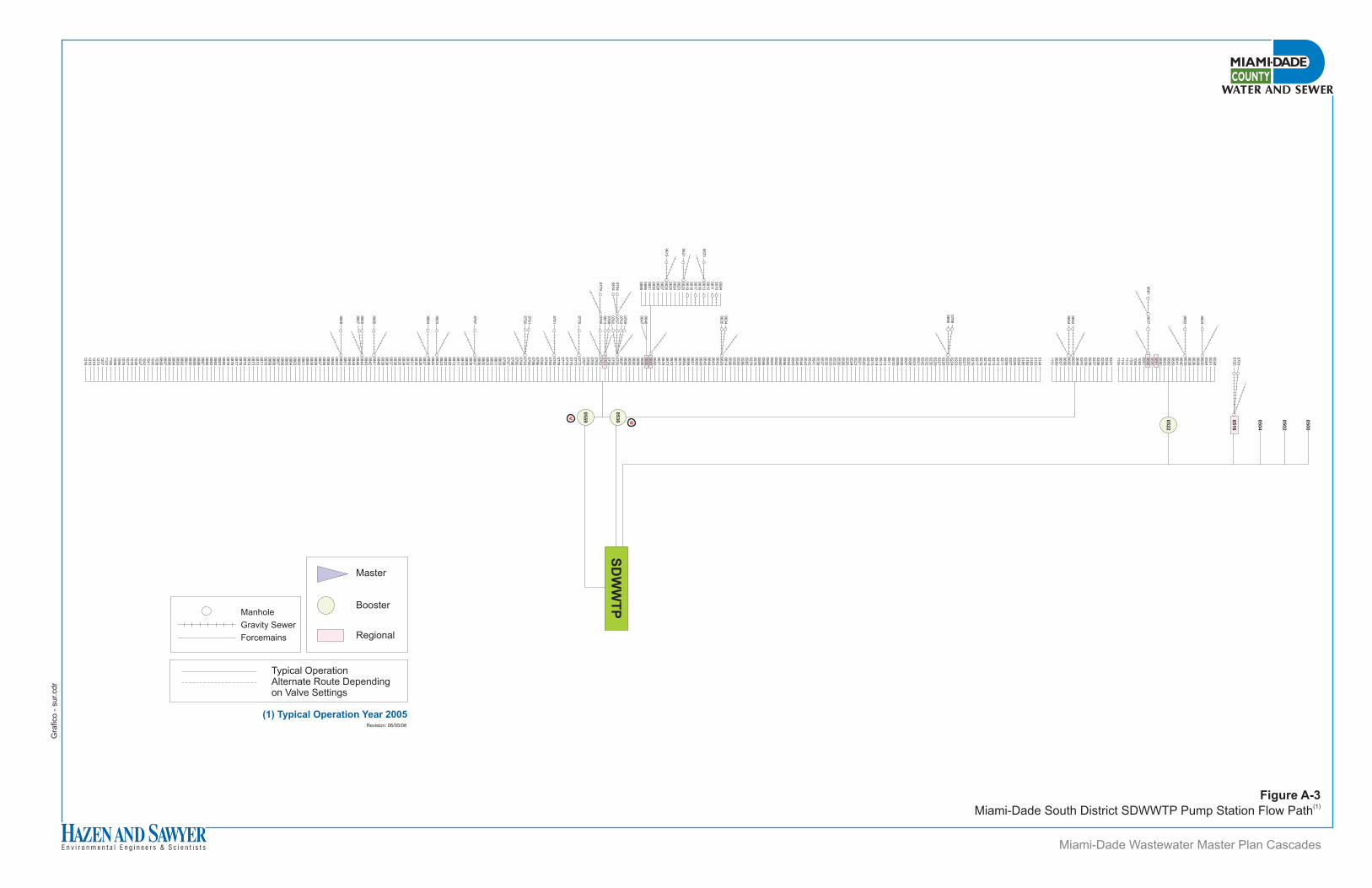
Gra
fico -
sur.
cdr
SD
WW
TP
05
00
05
02
05
04
05
22
07
01
07
20
06
04
06
62
06
37
066
1
02
31
02
34
02
35
02
36
02
37
02
38
02
39
02
41
06
48
06
53
06
55
06
56
06
57
06
99
111
0
06
52
06
54
05
16
05
34
05
51
05
64
06
00
06
08
06
36
06
38
06
39
06
40
06
41
06
59
06
60
06
63
06
80
06
81
06
95
06
98
09
51
10
83
10
94
11
03
111
3111
5111
8
06
34
06
35
059
40
57
00
611
061
20
61
30
61
60
61
70
61
80
61
90
62
00
62
30
62
40
62
50
62
60
62
70
62
80
63
00
63
10
68
60
89
8
0780
077
9
07
68
08
13
0769
0753
0757
0760
063
3
06
46
06
47
0770
0791
0792
0787
0833
0884
0845
0847
0849
075
40
81
4
01
44
01
53
01
83
01
84
01
85
02
04
02
06
02
07
02
09
02
11
02
12
02
13
02
14
02
15
02
16
02
17
02
19
02
20
02
21
02
22
02
23
02
24
02
25
02
26
02
27
02
29
02
30
02
32
02
42
05
01
05
03
05
06
05
07
05
08
05
09
05
10
05
11
05
12
05
13
05
14
05
15
05
19
05
20
05
21
05
23
05
24
05
25
05
26
05
30
05
32
05
33
05
35
05
37
05
38
05
41
05
42
05
43
05
44
05
45
05
53
05
54
05
56
05
60
05
62
05
63
05
65
05
66
05
69
05
76
05
79
05
85
05
86
05
93
05
95
05
96
06
14
06
29
06
42
06
43
06
44
06
45
06
49
06
50
06
51
06
58
06
64
06
70
06
71
06
72
06
73
06
76
06
77
06
82
06
83
06
85
06
88
06
89
06
90
06
93
06
96
06
97
07
55
07
56
07
58
07
61
07
62
07
63
07
65
07
66
07
67
07
72
07
73
07
75
07
76
07
77
07
78
07
82
07
83
07
84
07
85
07
86
07
88
07
90
07
93
07
94
07
95
07
96
07
97
07
98
08
00
08
01
08
02
08
03
08
05
08
06
08
07
08
08
08
09
08
10
08
11
08
12
08
20
08
22
08
23
08
24
08
25
08
26
08
27
08
28
08
30
08
31
08
32
08
34
08
35
08
36
08
37
08
38
08
39
08
40
08
41
08
42
08
43
08
44
08
46
08
48
08
50
08
51
08
52
08
53
08
54
08
55
08
56
08
57
08
58
08
59
08
60
08
61
08
62
08
63
08
64
08
65
08
66
08
67
08
68
08
69
08
70
08
71
08
72
08
73
08
74
08
75
08
76
08
77
08
78
08
79
08
80
08
81
08
82
08
83
08
86
08
87
08
88
08
89
08
90
08
91
08
92
08
93
08
94
08
96
08
97
08
99
10
38
10
40
10
41
10
42
10
47
10
48
10
76
10
77
10
78
10
95
10
98
11
06
11
23
12
07
12
13
12
14
12
15
12
16
05
36
05
59 M
M
07
89
08
95
062
1
061
5
0781
0885
Typical OperationAlternate Route Dependingon Valve Settings
Manhole
Gravity Sewer
Forcemains
Master
Booster
Regional
Revision: 06/05/08
(1) Typical Operation Year 2005
Miami-Dade Wastewater Master Plan Cascades
Figure A-3(1)
Miami-Dade South District SDWWTP Pump Station Flow Path
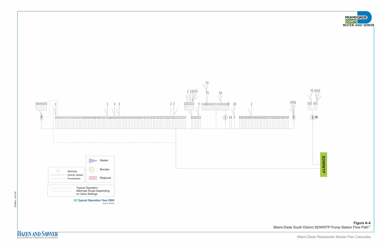
Gra
fico -
sur.
cdr
0816
0817
SD
WW
TP
0799
0804
0821
0829
05
59
M0527
0528
0531
0540
0546
0547
0549
0552
0555
0568
0572
0573
0574
0575
0577
0578
0580
0583
0584
0587
0588
0589
0590
0591
0592
0601
0602
0603
0607
0609
0610
0622
0632
0665
0557
0558
0700
0702
0703
0704
0705
0708
0709
0711
0712
0713
0714
0715
0718
0723
0724
0725
0726
0731
0732
0733
0734
0740
0741
0742
0743
0744
0745
0747
0750
0751
1009
1015
1016
1017
1018
1019
1021
1027
1028
1029
1030
1032
1033
1035
1036
1037
1043
1044
1045
1046
1049
1051
1052
1054
1055
1060
1065
1066
1068
1069
1071
1074
1075
1079
1081
1082
1086
1087
1088
1089
1090
1091
1092
1093
1096
1097
1099
1100
1101
1102
1104
1105
1107
1108
1109
1111
1114
1119
1120
1121
1124
1132
1133
1134
0707
1056
9721
0710
0719
0728
0730
0735
0736
0738
0597
0717
0739
0746
0729
0748
0722
0749
1053
1057
1064
1070
0678
0684
0687
0692
0706
0737
1058
1059
1061
1062
1063
1067
1005
1006
1022
1031
1023
1072
06
91
10
00
10
01
10
02
10
03
10
04
10
07
10
08
10
10
10
11
10
12
10
13
10
14
10
20
10
24
10
25
10
26
10
39
10
73
10
84
10
85
111
6112
7
0177
0240
0581
0815
0818
0819
0179
0180
0181
0582
0727
05
71
05
17
Master
Booster
Regional
Typical OperationAlternate Route Dependingon Valve Settings
Manhole
Gravity Sewer
Forcemains
Miami-Dade Wastewater Master Plan Cascades
Figure A-4(1)
Miami-Dade South District SDWWTP Pump Station Flow Path
Revision: 06/05/08
(1) Typical Operation Year 2005
APPENDIX B
EAMS Pump Station Database

THIS PAGE LEFT INTENTIONALLY BLANK
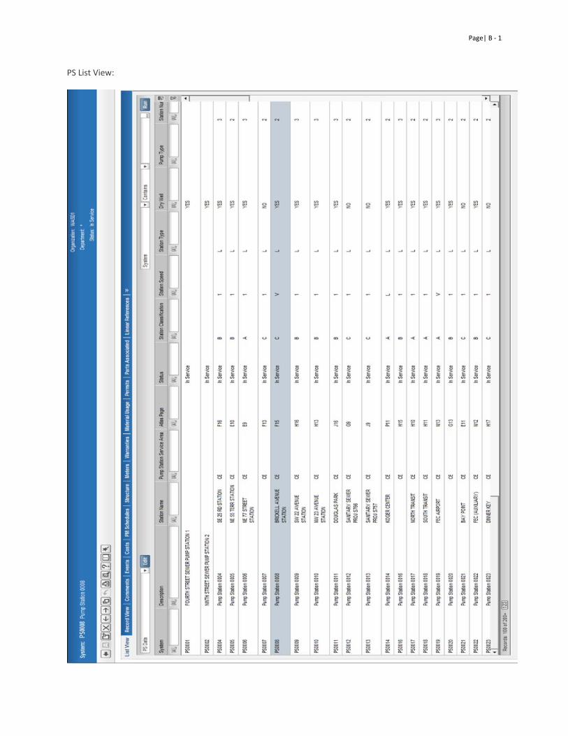
Page| B ‐ 1
PS List View:
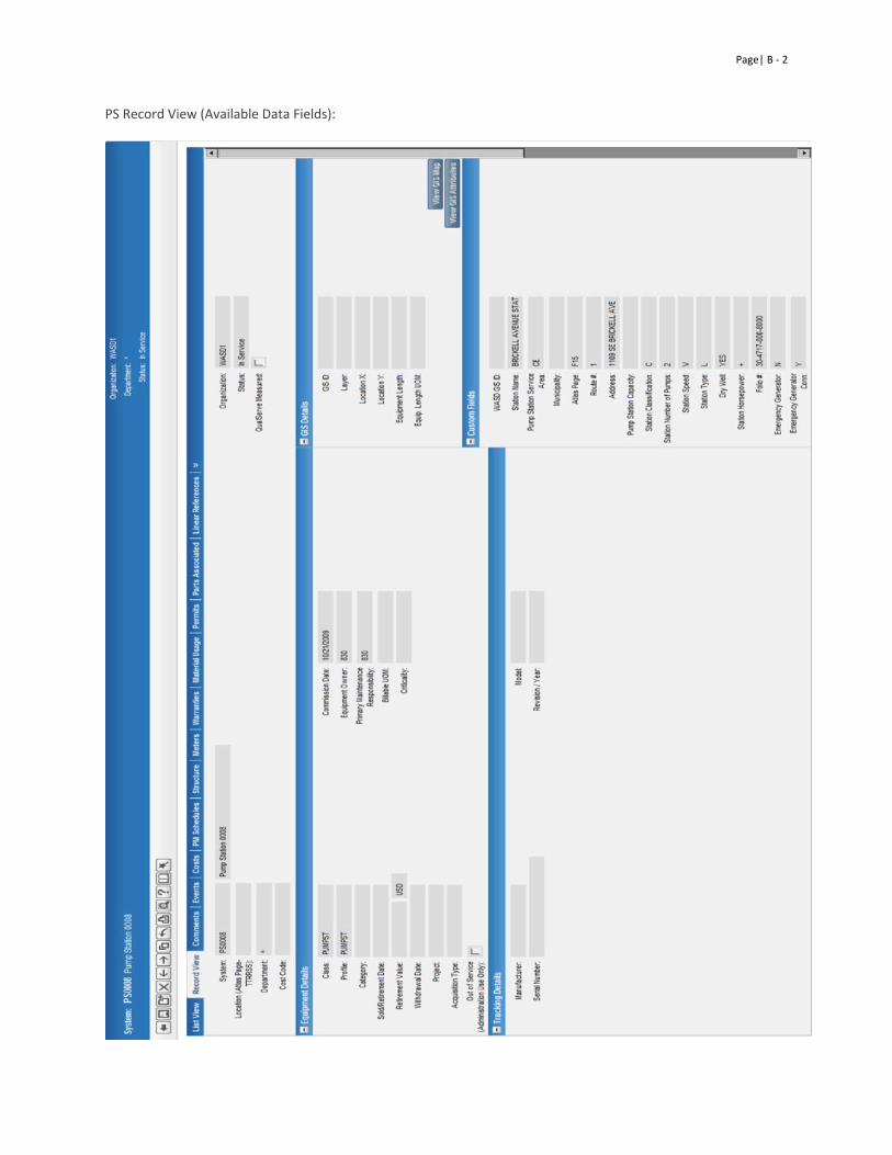
Page| B ‐ 2
PS Record View (Available Data Fields):
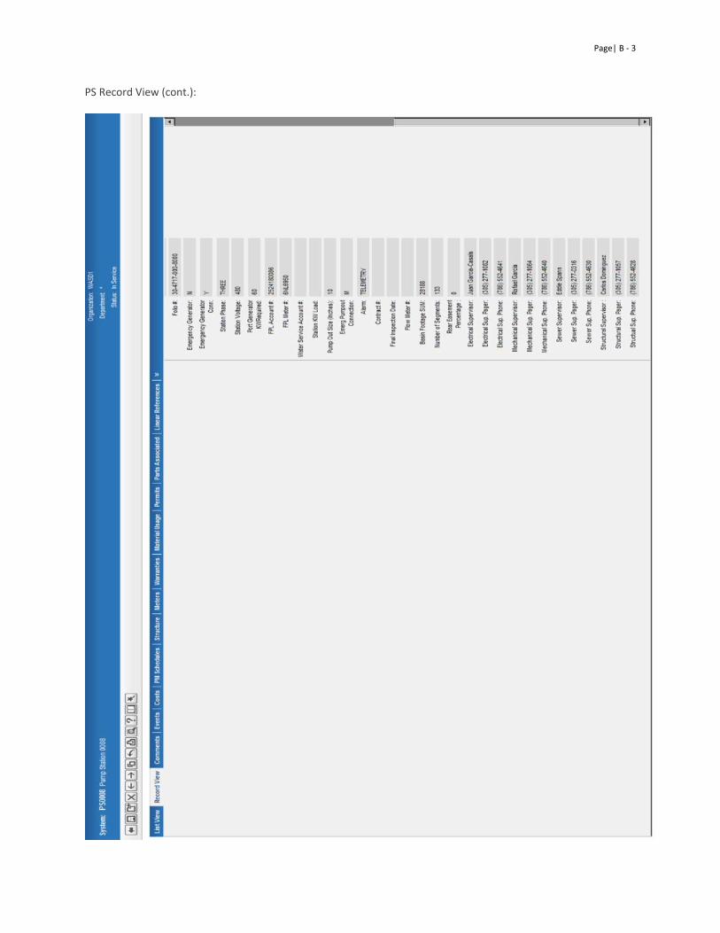
Page| B ‐ 3
PS Record View (cont.):
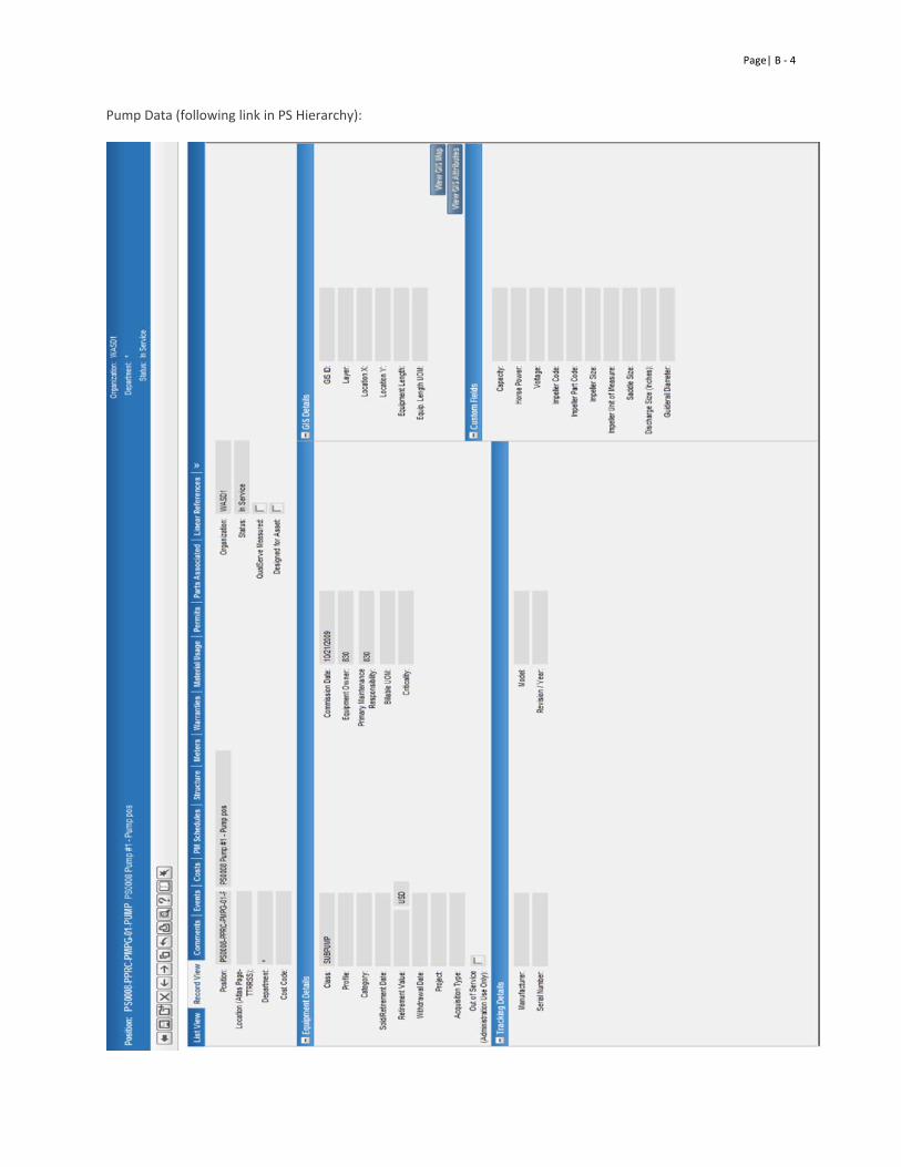
Page| B ‐ 4
Pump Data (following link in PS Hierarchy):
APPENDIX C
Routine and Preventative Maintenance Task Lists for the Trades

THIS PAGE LEFT INTENTIONALLY BLANK
Appendix C Table of Contents:
• Electrical Preventative Maintenance Task List Page |C – 1 • Mechanical Preventative Maintenance Task List Page |C – 8 • Routine Electrical Maintenance Task List Page |C – 13 • Routine Mechanical Maintenance Task List Page |C – 20 • Routine Structural Maintenance Task List Page |C – 25

THIS PAGE LEFT INTENTIONALLY BLANK
Page | C – 1
Electrical Preventative Maintenance

THIS PAGE LEFT INTENTIONALLY BLANK
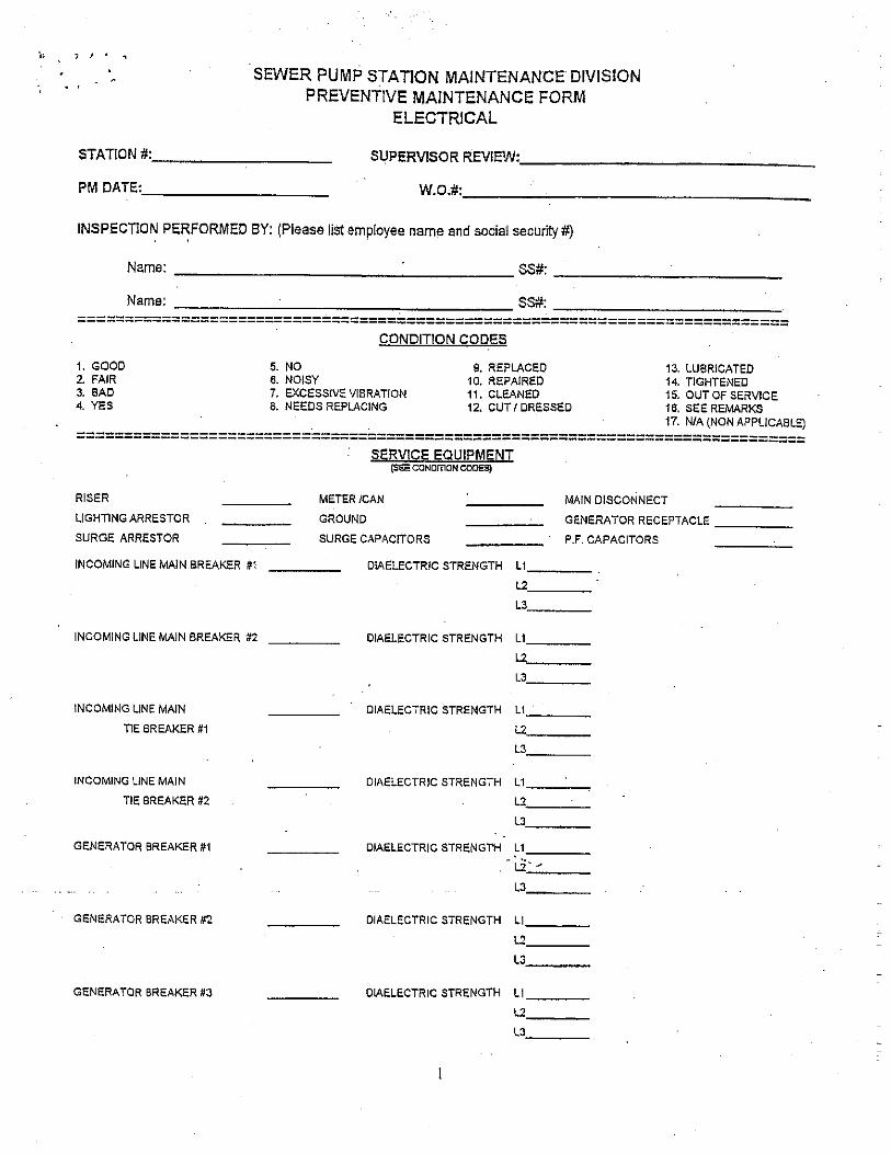
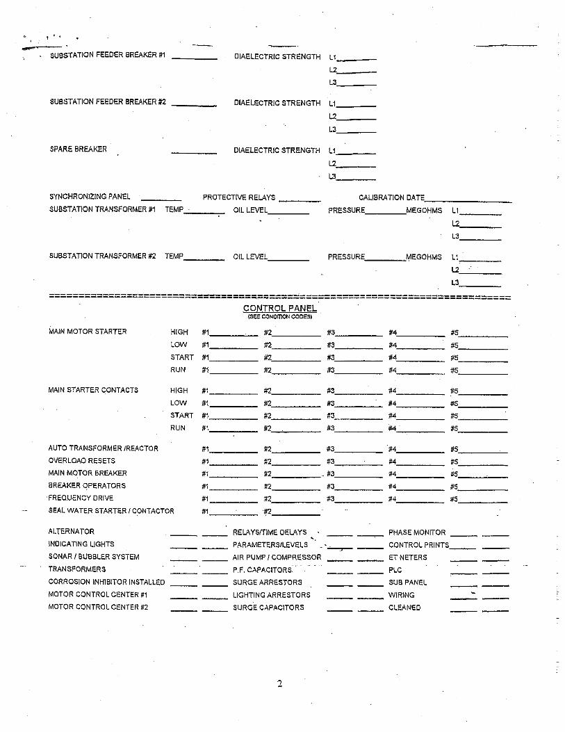
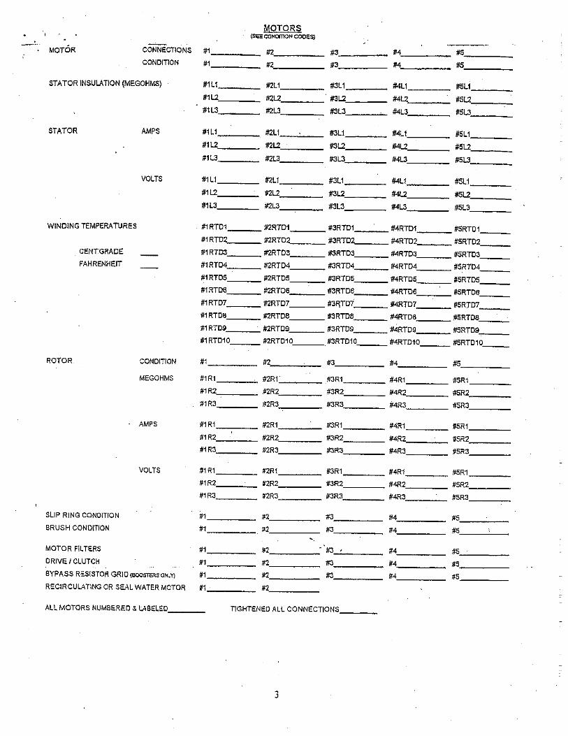
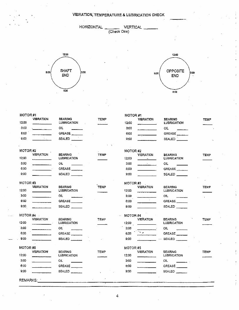
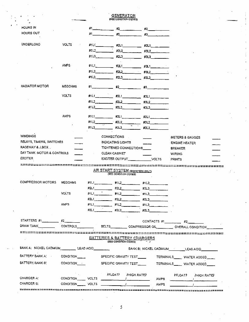
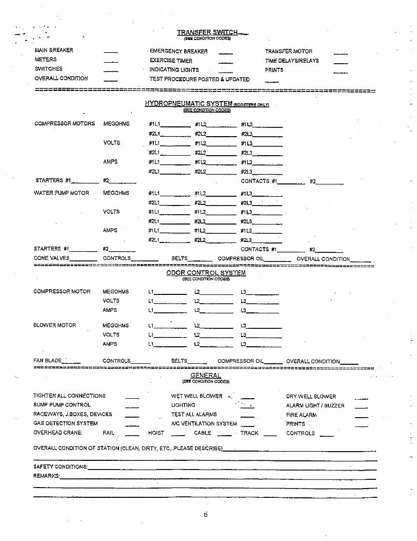
Page | C – 8
Mechanical Preventative Maintenance

THIS PAGE LEFT INTENTIONALLY BLANK
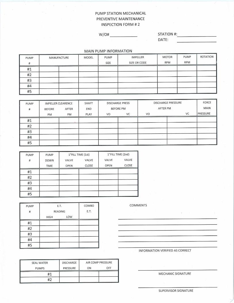
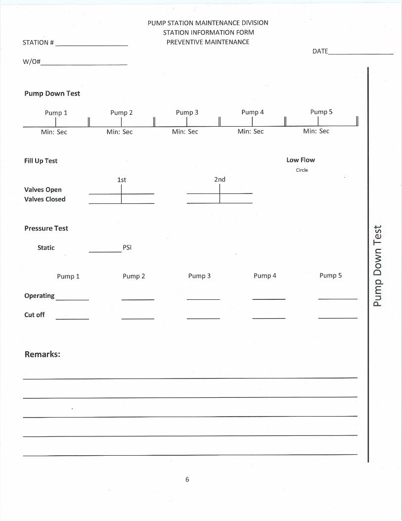
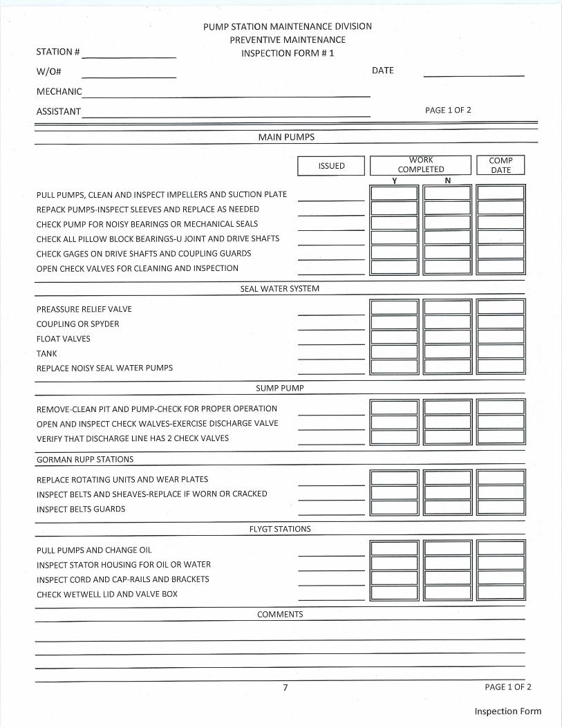
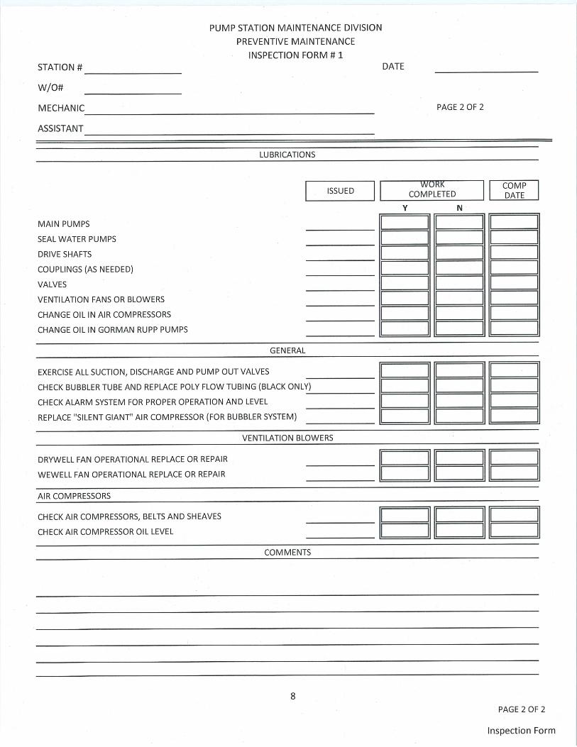
Page | C – 13
Electrical Routine Maintenance

THIS PAGE LEFT INTENTIONALLY BLANK
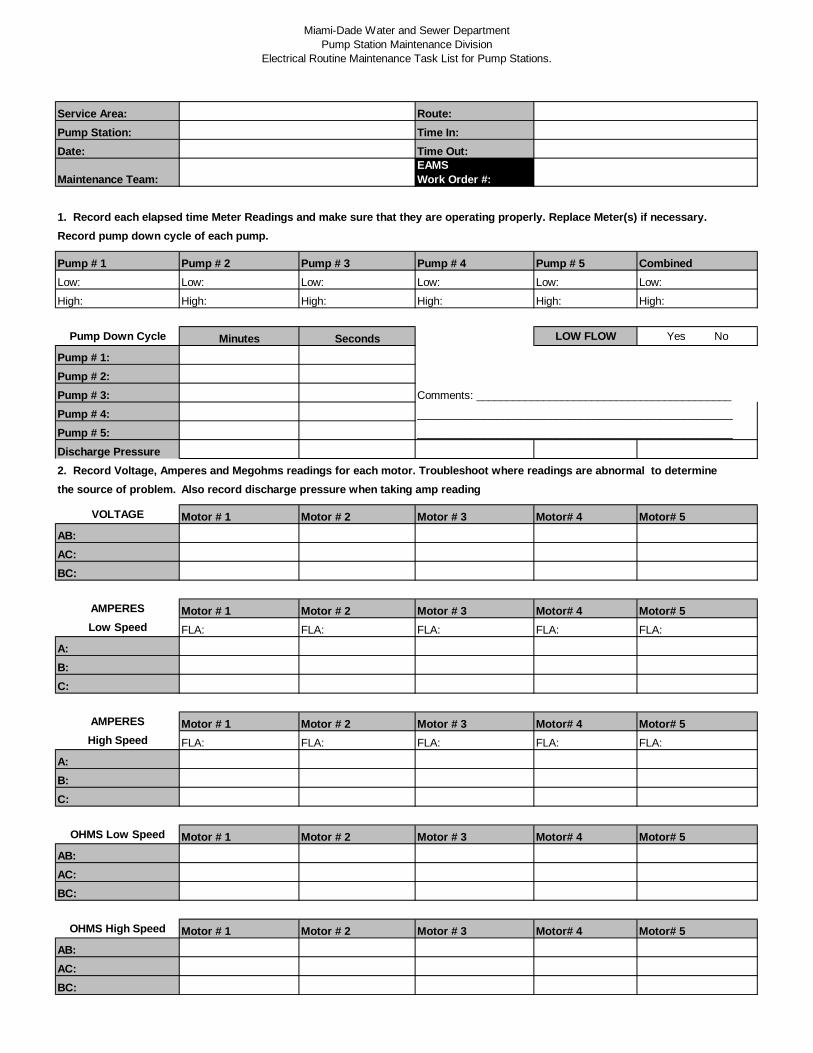
Miami-Dade Water and Sewer DepartmentPump Station Maintenance Division
Electrical Routine Maintenance Task List for Pump Stations.
Service Area: Route:Pump Station: Time In:Date: Time Out:
Maintenance Team:EAMSWork Order #:
1. Record each elapsed time Meter Readings and make sure that they are operating properly. Replace Meter(s) if necessary.Record pump down cycle of each pump.
Pump # 1 Pump # 2 Pump # 3 Pump # 4 Pump # 5 CombinedLow: Low: Low: Low: Low: Low:
High: High: High: High: High: High:
Pump Down Cycle Minutes Seconds LOW FLOW Yes No
Pump # 1:Pump # 2:Pump # 3: Comments: __________________________________________
Pump # 4: ____________________________________________________
Pump # 5: ____________________________________________________
Discharge Pressure2. Record Voltage, Amperes and Megohms readings for each motor. Troubleshoot where readings are abnormal to determinethe source of problem. Also record discharge pressure when taking amp reading
VOLTAGE Motor # 1 Motor # 2 Motor # 3 Motor# 4 Motor# 5AB:AC:BC:
AMPERES Motor # 1 Motor # 2 Motor # 3 Motor# 4 Motor# 5Low Speed FLA: FLA: FLA: FLA: FLA:
A:B:C:
AMPERES Motor # 1 Motor # 2 Motor # 3 Motor# 4 Motor# 5High Speed FLA: FLA: FLA: FLA: FLA:
A:B:C:
OHMS Low Speed Motor # 1 Motor # 2 Motor # 3 Motor# 4 Motor# 5AB:AC:BC:
OHMS High Speed Motor # 1 Motor # 2 Motor # 3 Motor# 4 Motor# 5AB:AC:BC:
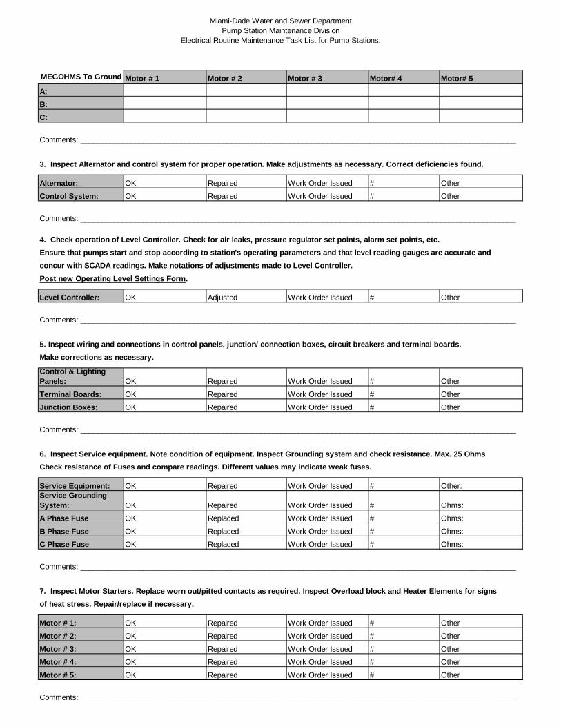
Miami-Dade Water and Sewer DepartmentPump Station Maintenance Division
Electrical Routine Maintenance Task List for Pump Stations.
MEGOHMS To Ground Motor # 1 Motor # 2 Motor # 3 Motor# 4 Motor# 5A:B:C:
Comments: ________________________________________________________________________________________________________
3. Inspect Alternator and control system for proper operation. Make adjustments as necessary. Correct deficiencies found.
Alternator: OK Repaired Work Order Issued # Other
Control System: OK Repaired Work Order Issued # Other
Comments: ________________________________________________________________________________________________________
4. Check operation of Level Controller. Check for air leaks, pressure regulator set points, alarm set points, etc.Ensure that pumps start and stop according to station's operating parameters and that level reading gauges are accurate andconcur with SCADA readings. Make notations of adjustments made to Level Controller.Post new Operating Level Settings Form.
Level Controller: OK Adjusted Work Order Issued # Other
Comments: ________________________________________________________________________________________________________
5. Inspect wiring and connections in control panels, junction/ connection boxes, circuit breakers and terminal boards.Make corrections as necessary.
Control & LightingPanels: OK Repaired Work Order Issued # Other
Terminal Boards: OK Repaired Work Order Issued # Other
Junction Boxes: OK Repaired Work Order Issued # Other
Comments: ________________________________________________________________________________________________________
6. Inspect Service equipment. Note condition of equipment. Inspect Grounding system and check resistance. Max. 25 OhmsCheck resistance of Fuses and compare readings. Different values may indicate weak fuses.
Service Equipment: OK Repaired Work Order Issued # Other:Service GroundingSystem: OK Repaired Work Order Issued # Ohms:
A Phase Fuse OK Replaced Work Order Issued # Ohms:
B Phase Fuse OK Replaced Work Order Issued # Ohms:
C Phase Fuse OK Replaced Work Order Issued # Ohms:
Comments: ________________________________________________________________________________________________________
7. Inspect Motor Starters. Replace worn out/pitted contacts as required. Inspect Overload block and Heater Elements for signsof heat stress. Repair/replace if necessary.
Motor # 1: OK Repaired Work Order Issued # Other
Motor # 2: OK Repaired Work Order Issued # Other
Motor # 3: OK Repaired Work Order Issued # Other
Motor # 4: OK Repaired Work Order Issued # Other
Motor # 5: OK Repaired Work Order Issued # Other
Comments: ________________________________________________________________________________________________________
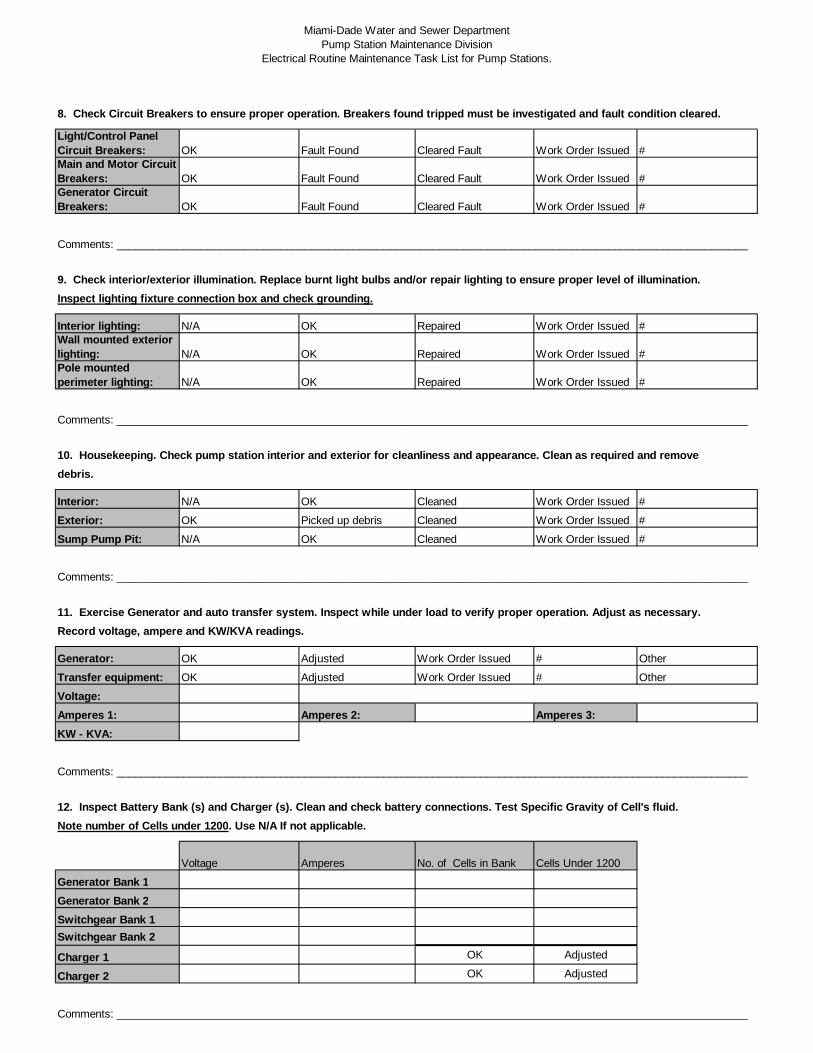
Miami-Dade Water and Sewer DepartmentPump Station Maintenance Division
Electrical Routine Maintenance Task List for Pump Stations.
8. Check Circuit Breakers to ensure proper operation. Breakers found tripped must be investigated and fault condition cleared.
Light/Control PanelCircuit Breakers: OK Fault Found Cleared Fault Work Order Issued #Main and Motor CircuitBreakers: OK Fault Found Cleared Fault Work Order Issued #Generator CircuitBreakers: OK Fault Found Cleared Fault Work Order Issued #
Comments: ________________________________________________________________________________________________________
9. Check interior/exterior illumination. Replace burnt light bulbs and/or repair lighting to ensure proper level of illumination.Inspect lighting fixture connection box and check grounding.
Interior lighting: N/A OK Repaired Work Order Issued #Wall mounted exteriorlighting: N/A OK Repaired Work Order Issued #Pole mountedperimeter lighting: N/A OK Repaired Work Order Issued #
Comments: ________________________________________________________________________________________________________
10. Housekeeping. Check pump station interior and exterior for cleanliness and appearance. Clean as required and removedebris.
Interior: N/A OK Cleaned Work Order Issued #
Exterior: OK Picked up debris Cleaned Work Order Issued #
Sump Pump Pit: N/A OK Cleaned Work Order Issued #
Comments: ________________________________________________________________________________________________________
11. Exercise Generator and auto transfer system. Inspect while under load to verify proper operation. Adjust as necessary.Record voltage, ampere and KW/KVA readings.
Generator: OK Adjusted Work Order Issued # Other
Transfer equipment: OK Adjusted Work Order Issued # Other
Voltage:Amperes 1: Amperes 2: Amperes 3:KW - KVA:
Comments: ________________________________________________________________________________________________________
12. Inspect Battery Bank (s) and Charger (s). Clean and check battery connections. Test Specific Gravity of Cell's fluid.Note number of Cells under 1200. Use N/A If not applicable.
Voltage Amperes No. of Cells in Bank Cells Under 1200
Generator Bank 1Generator Bank 2Switchgear Bank 1Switchgear Bank 2
Charger 1 OK Adjusted
Charger 2 OK Adjusted
Comments: ________________________________________________________________________________________________________
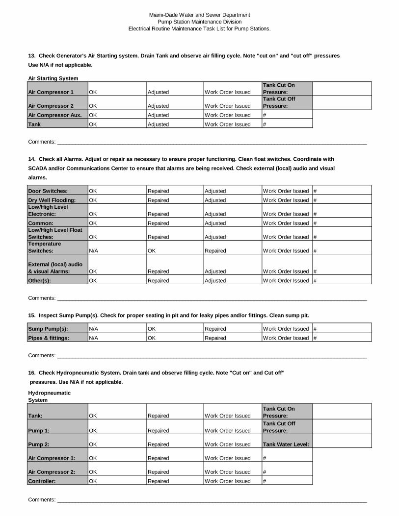
Miami-Dade Water and Sewer DepartmentPump Station Maintenance Division
Electrical Routine Maintenance Task List for Pump Stations.
13. Check Generator's Air Starting system. Drain Tank and observe air filling cycle. Note "cut on" and "cut off" pressuresUse N/A if not applicable.
Air Starting System
Air Compressor 1 OK Adjusted Work Order IssuedTank Cut OnPressure:
Air Compressor 2 OK Adjusted Work Order IssuedTank Cut OffPressure:
Air Compressor Aux. OK Adjusted Work Order Issued #
Tank OK Adjusted Work Order Issued #
Comments: ________________________________________________________________________________________________________
14. Check all Alarms. Adjust or repair as necessary to ensure proper functioning. Clean float switches. Coordinate withSCADA and/or Communications Center to ensure that alarms are being received. Check external (local) audio and visualalarms.
Door Switches: OK Repaired Adjusted Work Order Issued #
Dry Well Flooding: OK Repaired Adjusted Work Order Issued #Low/High LevelElectronic: OK Repaired Adjusted Work Order Issued #
Common: OK Repaired Adjusted Work Order Issued #Low/High Level FloatSwitches: OK Repaired Adjusted Work Order Issued #TemperatureSwitches: N/A OK Repaired Work Order Issued #
External (local) audio& visual Alarms: OK Repaired Adjusted Work Order Issued #
Other(s): OK Repaired Adjusted Work Order Issued #
Comments: ________________________________________________________________________________________________________
15. Inspect Sump Pump(s). Check for proper seating in pit and for leaky pipes and/or fittings. Clean sump pit.
Sump Pump(s): N/A OK Repaired Work Order Issued #
Pipes & fittings: N/A OK Repaired Work Order Issued #
Comments: ________________________________________________________________________________________________________
16. Check Hydropneumatic System. Drain tank and observe filling cycle. Note "Cut on" and Cut off" pressures. Use N/A if not applicable.
HydropneumaticSystem
Tank: OK Repaired Work Order IssuedTank Cut OnPressure:
Pump 1: OK Repaired Work Order IssuedTank Cut OffPressure:
Pump 2: OK Repaired Work Order Issued Tank Water Level:
Air Compressor 1: OK Repaired Work Order Issued #
Air Compressor 2: OK Repaired Work Order Issued #
Controller: OK Repaired Work Order Issued #
Comments: ________________________________________________________________________________________________________
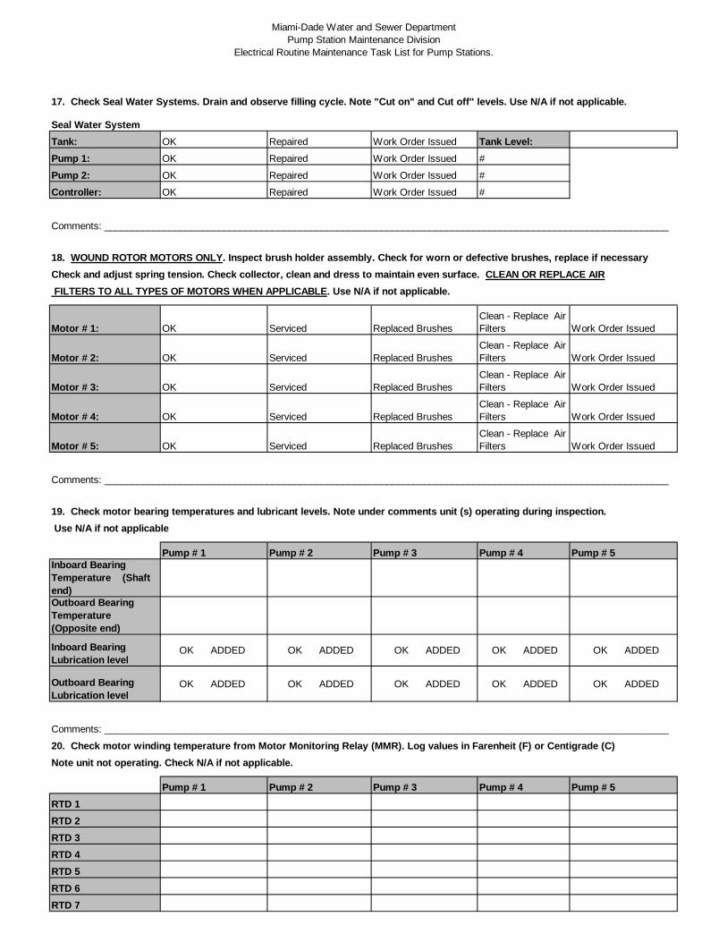
Miami-Dade Water and Sewer DepartmentPump Station Maintenance Division
Electrical Routine Maintenance Task List for Pump Stations.
17. Check Seal Water Systems. Drain and observe filling cycle. Note "Cut on" and Cut off" levels. Use N/A if not applicable.
Seal Water SystemTank: OK Repaired Work Order Issued Tank Level:Pump 1: OK Repaired Work Order Issued #
Pump 2: OK Repaired Work Order Issued #
Controller: OK Repaired Work Order Issued #
Comments: ________________________________________________________________________________________________________
18. WOUND ROTOR MOTORS ONLY. Inspect brush holder assembly. Check for worn or defective brushes, replace if necessaryCheck and adjust spring tension. Check collector, clean and dress to maintain even surface. CLEAN OR REPLACE AIR FILTERS TO ALL TYPES OF MOTORS WHEN APPLICABLE. Use N/A if not applicable.
Motor # 1: OK Serviced Replaced BrushesClean - Replace AirFilters Work Order Issued
Motor # 2: OK Serviced Replaced BrushesClean - Replace AirFilters Work Order Issued
Motor # 3: OK Serviced Replaced BrushesClean - Replace AirFilters Work Order Issued
Motor # 4: OK Serviced Replaced BrushesClean - Replace AirFilters Work Order Issued
Motor # 5: OK Serviced Replaced BrushesClean - Replace AirFilters Work Order Issued
Comments: ________________________________________________________________________________________________________
19. Check motor bearing temperatures and lubricant levels. Note under comments unit (s) operating during inspection. Use N/A if not applicable
Pump # 1 Pump # 2 Pump # 3 Pump # 4 Pump # 5Inboard BearingTemperature (Shaftend)Outboard BearingTemperature(Opposite end)
Inboard BearingLubrication level
OK ADDED OK ADDED OK ADDED OK ADDED OK ADDED
Outboard BearingLubrication level
OK ADDED OK ADDED OK ADDED OK ADDED OK ADDED
Comments: ________________________________________________________________________________________________________
20. Check motor winding temperature from Motor Monitoring Relay (MMR). Log values in Farenheit (F) or Centigrade (C)Note unit not operating. Check N/A if not applicable.
Pump # 1 Pump # 2 Pump # 3 Pump # 4 Pump # 5RTD 1RTD 2RTD 3RTD 4RTD 5RTD 6RTD 7
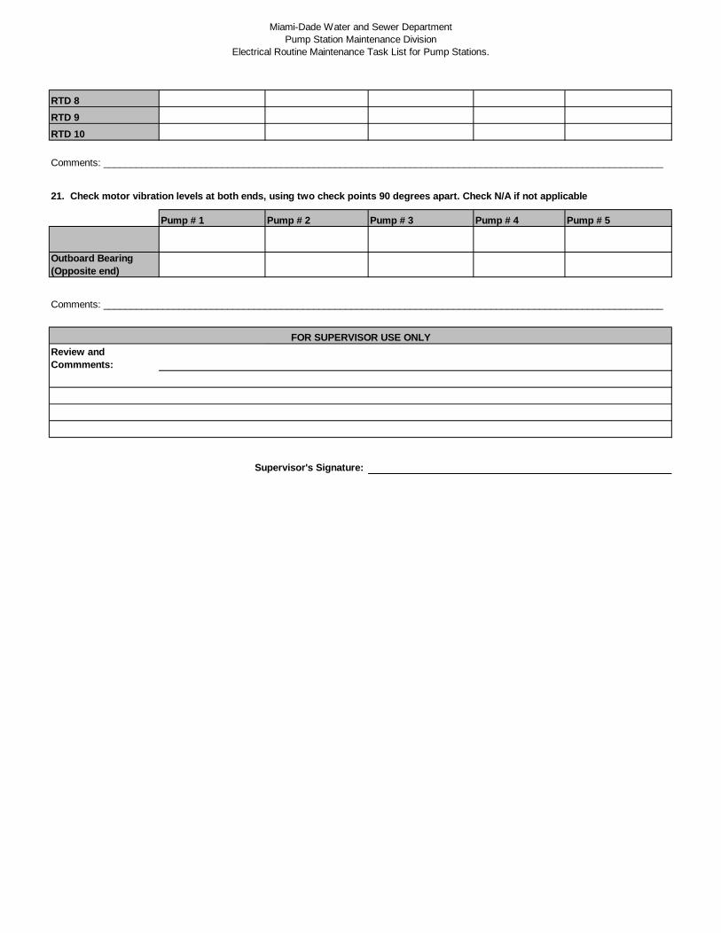
Miami-Dade Water and Sewer DepartmentPump Station Maintenance Division
Electrical Routine Maintenance Task List for Pump Stations.
RTD 8RTD 9RTD 10
Comments: ________________________________________________________________________________________________________
21. Check motor vibration levels at both ends, using two check points 90 degrees apart. Check N/A if not applicable
Pump # 1 Pump # 2 Pump # 3 Pump # 4 Pump # 5
Outboard Bearing(Opposite end)
Comments: ________________________________________________________________________________________________________
Review andCommments:
Supervisor's Signature:
FOR SUPERVISOR USE ONLY
Page | C – 20
Mechanical Routine Maintenance

THIS PAGE LEFT INTENTIONALLY BLANK
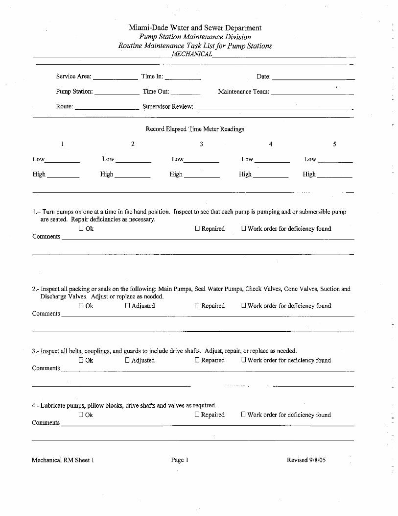
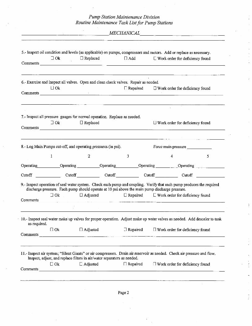
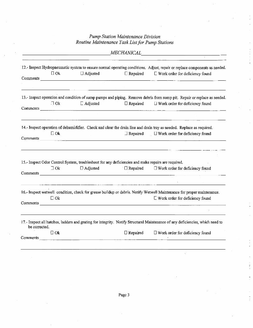
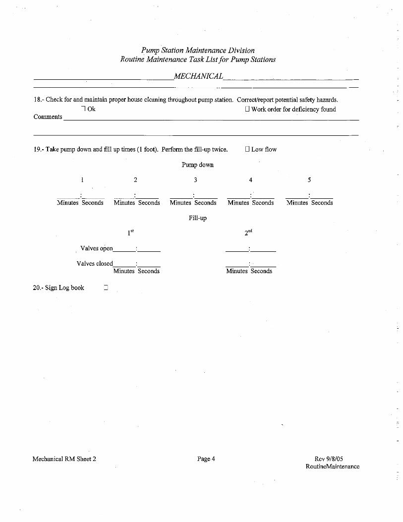
Page | C – 25
Structural Routine Maintenance

THIS PAGE LEFT INTENTIONALLY BLANK
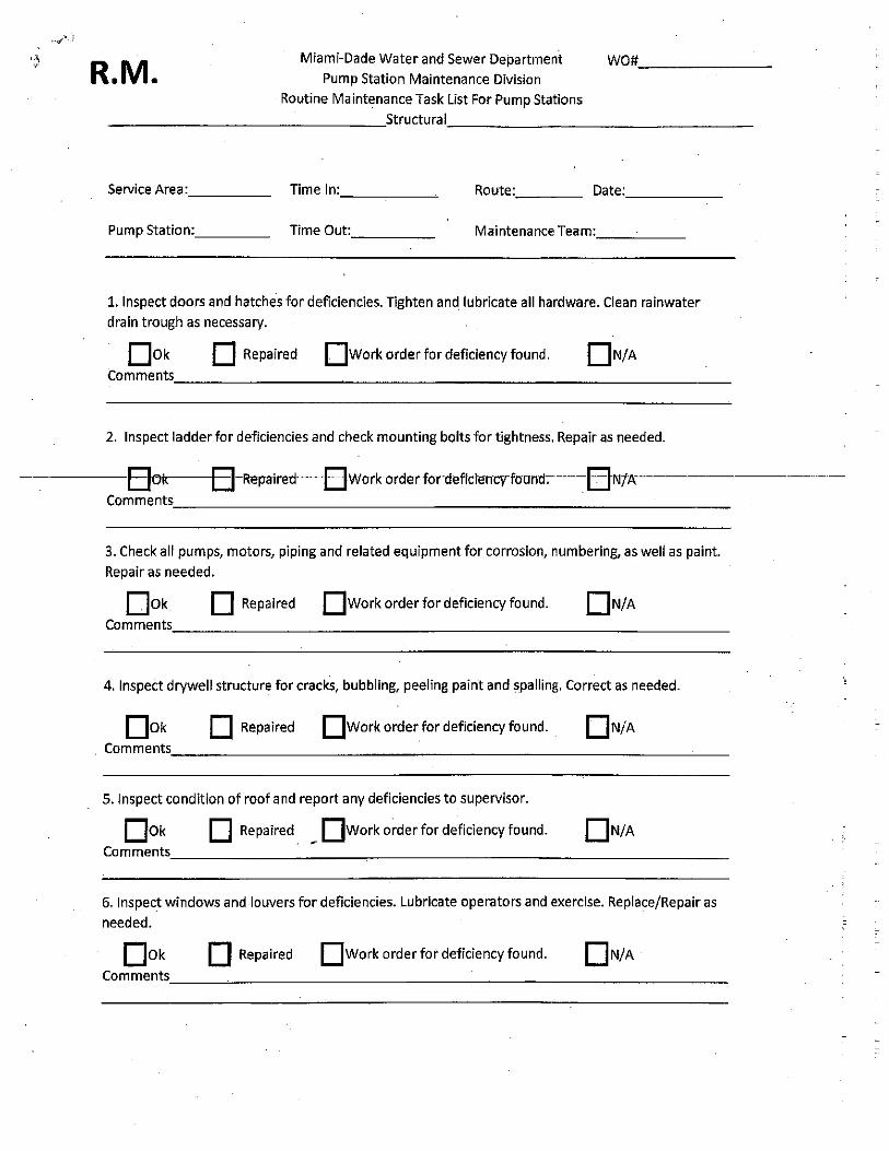
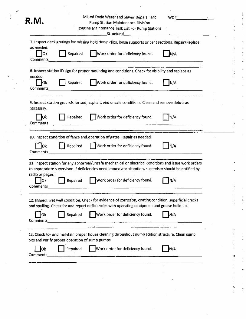
APPENDIX D
Pump Station Meter Inventory

THIS PAGE LEFT INTENTIONALLY BLANK
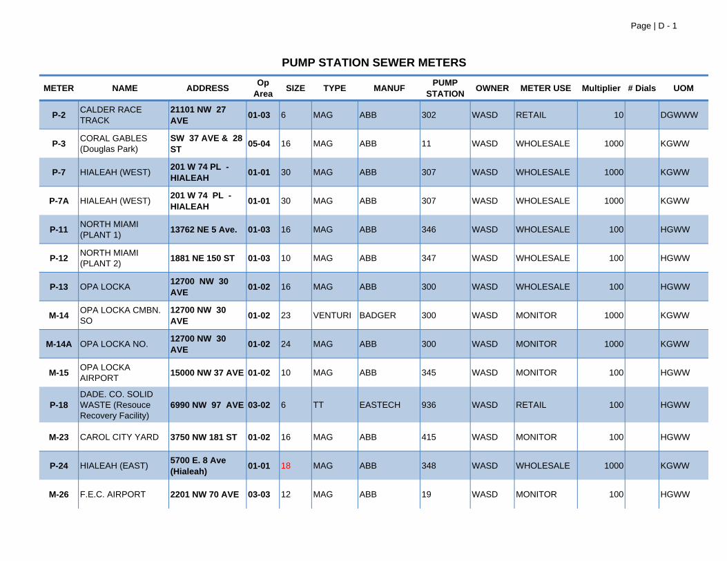
Page | D - 1
METER NAME ADDRESS Op Area SIZE TYPE MANUF PUMP
STATION OWNER METER USE Multiplier # Dials UOM
P-2 CALDER RACE TRACK
21101 NW 27 AVE 01-03 6 MAG ABB 302 WASD RETAIL 10 DGWWW
P-3 CORAL GABLES (Douglas Park)
SW 37 AVE & 28 ST 05-04 16 MAG ABB 11 WASD WHOLESALE 1000 KGWW
P-7 HIALEAH (WEST) 201 W 74 PL - HIALEAH 01-01 30 MAG ABB 307 WASD WHOLESALE 1000 KGWW
P-7A HIALEAH (WEST) 201 W 74 PL - HIALEAH 01-01 30 MAG ABB 307 WASD WHOLESALE 1000 KGWW
P-11 NORTH MIAMI (PLANT 1)
13762 NE 5 Ave. 01-03 16 MAG ABB 346 WASD WHOLESALE 100 HGWW
P-12 NORTH MIAMI (PLANT 2)
1881 NE 150 ST 01-03 10 MAG ABB 347 WASD WHOLESALE 100 HGWW
P-13 OPA LOCKA 12700 NW 30 AVE 01-02 16 MAG ABB 300 WASD WHOLESALE 100 HGWW
M-14 OPA LOCKA CMBN. SO
12700 NW 30 AVE 01-02 23 VENTURI BADGER 300 WASD MONITOR 1000 KGWW
M-14A OPA LOCKA NO.12700 NW 30 AVE 01-02 24 MAG ABB 300 WASD MONITOR 1000 KGWW
M-15 OPA LOCKA AIRPORT
15000 NW 37 AVE 01-02 10 MAG ABB 345 WASD MONITOR 100 HGWW
P-18DADE. CO. SOLID WASTE (Resouce Recovery Facility)
6990 NW 97 AVE 03-02 6 TT EASTECH 936 WASD RETAIL 100 HGWW
M-23 CAROL CITY YARD 3750 NW 181 ST 01-02 16 MAG ABB 415 WASD MONITOR 100 HGWW
P-24 HIALEAH (EAST) 5700 E. 8 Ave (Hialeah) 01-01 18 MAG ABB 348 WASD WHOLESALE 1000 KGWW
M-26 F.E.C. AIRPORT 2201 NW 70 AVE 03-03 12 MAG ABB 19 WASD MONITOR 100 HGWW
PUMP STATION SEWER METERS
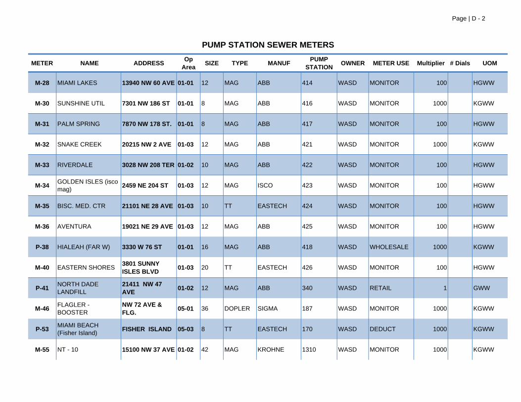
Page | D - 2
METER NAME ADDRESS Op Area SIZE TYPE MANUF PUMP
STATION OWNER METER USE Multiplier # Dials UOM
PUMP STATION SEWER METERS
M-28 MIAMI LAKES 13940 NW 60 AVE 01-01 12 MAG ABB 414 WASD MONITOR 100 HGWW
M-30 SUNSHINE UTIL 7301 NW 186 ST 01-01 8 MAG ABB 416 WASD MONITOR 1000 KGWW
M-31 PALM SPRING 7870 NW 178 ST. 01-01 8 MAG ABB 417 WASD MONITOR 100 HGWW
M-32 SNAKE CREEK 20215 NW 2 AVE 01-03 12 MAG ABB 421 WASD MONITOR 1000 KGWW
M-33 RIVERDALE 3028 NW 208 TER 01-02 10 MAG ABB 422 WASD MONITOR 100 HGWW
M-34 GOLDEN ISLES (isco mag)
2459 NE 204 ST 01-03 12 MAG ISCO 423 WASD MONITOR 100 HGWW
M-35 BISC. MED. CTR 21101 NE 28 AVE 01-03 10 TT EASTECH 424 WASD MONITOR 100 HGWW
M-36 AVENTURA 19021 NE 29 AVE 01-03 12 MAG ABB 425 WASD MONITOR 100 HGWW
P-38 HIALEAH (FAR W) 3330 W 76 ST 01-01 16 MAG ABB 418 WASD WHOLESALE 1000 KGWW
M-40 EASTERN SHORES3801 SUNNY ISLES BLVD 01-03 20 TT EASTECH 426 WASD MONITOR 100 HGWW
P-41 NORTH DADE LANDFILL
21411 NW 47 AVE 01-02 12 MAG ABB 340 WASD RETAIL 1 GWW
M-46 FLAGLER - BOOSTER
NW 72 AVE & FLG. 05-01 36 DOPLER SIGMA 187 WASD MONITOR 1000 KGWW
P-53 MIAMI BEACH (Fisher Island)
FISHER ISLAND 05-03 8 TT EASTECH 170 WASD DEDUCT 1000 KGWW
M-55 NT - 10 15100 NW 37 AVE 01-02 42 MAG KROHNE 1310 WASD MONITOR 1000 KGWW
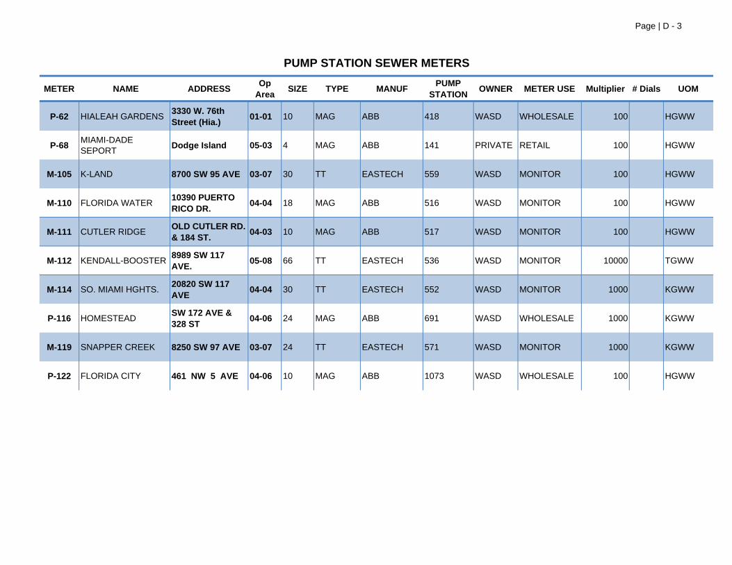
Page | D - 3
METER NAME ADDRESS Op Area SIZE TYPE MANUF PUMP
STATION OWNER METER USE Multiplier # Dials UOM
PUMP STATION SEWER METERS
P-62 HIALEAH GARDENS3330 W. 76th Street (Hia.) 01-01 10 MAG ABB 418 WASD WHOLESALE 100 HGWW
P-68 MIAMI-DADE SEPORT
Dodge Island 05-03 4 MAG ABB 141 PRIVATE RETAIL 100 HGWW
M-105 K-LAND 8700 SW 95 AVE 03-07 30 TT EASTECH 559 WASD MONITOR 100 HGWW
M-110 FLORIDA WATER10390 PUERTO RICO DR. 04-04 18 MAG ABB 516 WASD MONITOR 100 HGWW
M-111 CUTLER RIDGEOLD CUTLER RD. & 184 ST. 04-03 10 MAG ABB 517 WASD MONITOR 100 HGWW
M-112 KENDALL-BOOSTER8989 SW 117 AVE. 05-08 66 TT EASTECH 536 WASD MONITOR 10000 TGWW
M-114 SO. MIAMI HGHTS.20820 SW 117 AVE 04-04 30 TT EASTECH 552 WASD MONITOR 1000 KGWW
P-116 HOMESTEAD SW 172 AVE & 328 ST 04-06 24 MAG ABB 691 WASD WHOLESALE 1000 KGWW
M-119 SNAPPER CREEK 8250 SW 97 AVE 03-07 24 TT EASTECH 571 WASD MONITOR 1000 KGWW
P-122 FLORIDA CITY 461 NW 5 AVE 04-06 10 MAG ABB 1073 WASD WHOLESALE 100 HGWW

THIS PAGE LEFT INTENTIONALLY BLANK
APPENDIX E
SCADA Maintenance Task List

THIS PAGE LEFT INTENTIONALLY BLANK
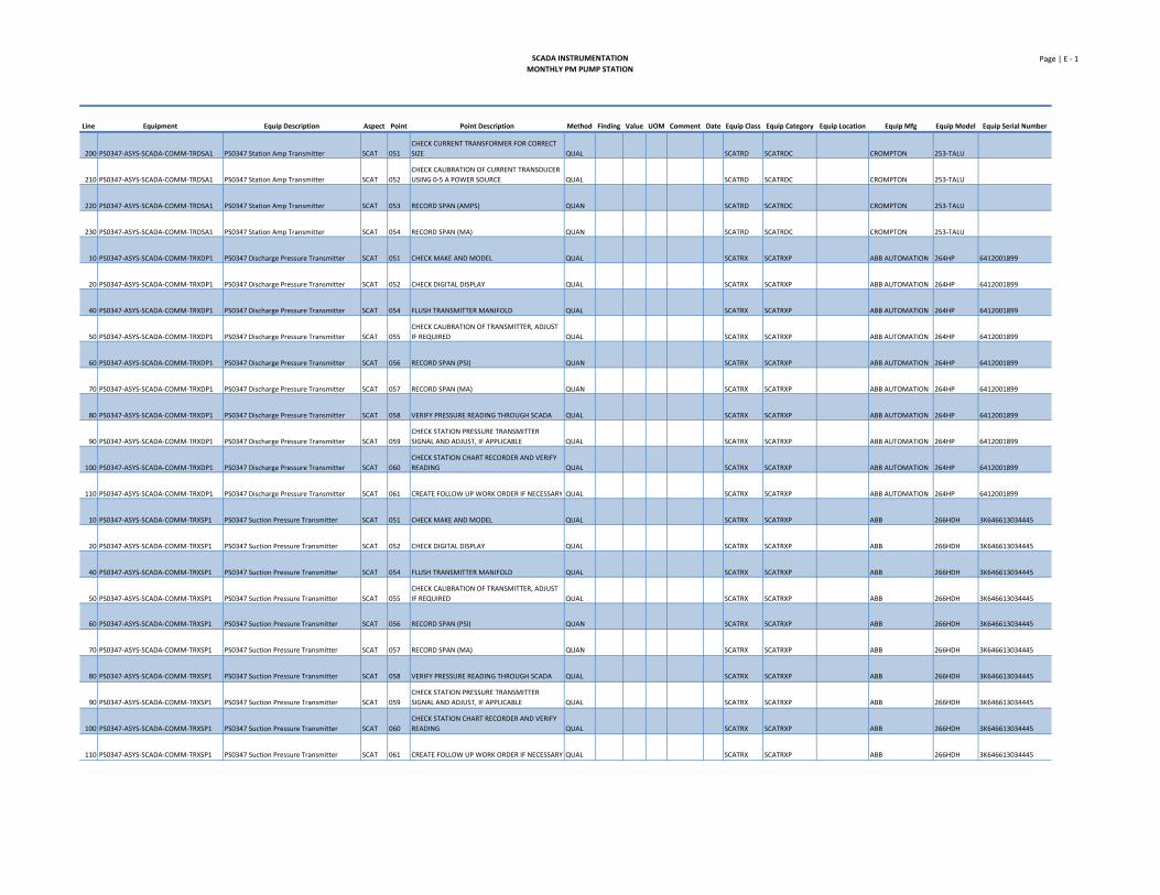
SCADA INSTRUMENTATIONMONTHLY PM PUMP STATION
Page | E ‐ 1
Line Equipment Equip Description Aspect Point Point Description Method Finding Value UOM Comment Date Equip Class Equip Category Equip Location Equip Mfg Equip Model Equip Serial Number
200 PS0347‐ASYS‐SCADA‐COMM‐TRDSA1 PS0347 Station Amp Transmitter SCAT 051
CHECK CURRENT TRANSFORMER FOR CORRECT
SIZE QUAL SCATRD SCATRDC CROMPTON 253‐TALU
210 PS0347‐ASYS‐SCADA‐COMM‐TRDSA1 PS0347 Station Amp Transmitter SCAT 052
CHECK CALIBRATION OF CURRENT TRANSDUCER
USING 0‐5 A POWER SOURCE QUAL SCATRD SCATRDC CROMPTON 253‐TALU
220 PS0347‐ASYS‐SCADA‐COMM‐TRDSA1 PS0347 Station Amp Transmitter SCAT 053 RECORD SPAN (AMPS) QUAN SCATRD SCATRDC CROMPTON 253‐TALU
230 PS0347‐ASYS‐SCADA‐COMM‐TRDSA1 PS0347 Station Amp Transmitter SCAT 054 RECORD SPAN (MA) QUAN SCATRD SCATRDC CROMPTON 253‐TALU
10 PS0347‐ASYS‐SCADA‐COMM‐TRXDP1 PS0347 Discharge Pressure Transmitter SCAT 051 CHECK MAKE AND MODEL QUAL SCATRX SCATRXP ABB AUTOMATION 264HP 6412001899
20 PS0347‐ASYS‐SCADA‐COMM‐TRXDP1 PS0347 Discharge Pressure Transmitter SCAT 052 CHECK DIGITAL DISPLAY QUAL SCATRX SCATRXP ABB AUTOMATION 264HP 6412001899
40 PS0347‐ASYS‐SCADA‐COMM‐TRXDP1 PS0347 Discharge Pressure Transmitter SCAT 054 FLUSH TRANSMITTER MANIFOLD QUAL SCATRX SCATRXP ABB AUTOMATION 264HP 6412001899
50 PS0347‐ASYS‐SCADA‐COMM‐TRXDP1 PS0347 Discharge Pressure Transmitter SCAT 055
CHECK CALIBRATION OF TRANSMITTER, ADJUST
IF REQUIRED QUAL SCATRX SCATRXP ABB AUTOMATION 264HP 6412001899
60 PS0347‐ASYS‐SCADA‐COMM‐TRXDP1 PS0347 Discharge Pressure Transmitter SCAT 056 RECORD SPAN (PSI) QUAN SCATRX SCATRXP ABB AUTOMATION 264HP 6412001899
70 PS0347‐ASYS‐SCADA‐COMM‐TRXDP1 PS0347 Discharge Pressure Transmitter SCAT 057 RECORD SPAN (MA) QUAN SCATRX SCATRXP ABB AUTOMATION 264HP 6412001899
80 PS0347‐ASYS‐SCADA‐COMM‐TRXDP1 PS0347 Discharge Pressure Transmitter SCAT 058 VERIFY PRESSURE READING THROUGH SCADA QUAL SCATRX SCATRXP ABB AUTOMATION 264HP 6412001899
90 PS0347‐ASYS‐SCADA‐COMM‐TRXDP1 PS0347 Discharge Pressure Transmitter SCAT 059
CHECK STATION PRESSURE TRANSMITTER
SIGNAL AND ADJUST, IF APPLICABLE QUAL SCATRX SCATRXP ABB AUTOMATION 264HP 6412001899
100 PS0347‐ASYS‐SCADA‐COMM‐TRXDP1 PS0347 Discharge Pressure Transmitter SCAT 060
CHECK STATION CHART RECORDER AND VERIFY
READING QUAL SCATRX SCATRXP ABB AUTOMATION 264HP 6412001899
110 PS0347‐ASYS‐SCADA‐COMM‐TRXDP1 PS0347 Discharge Pressure Transmitter SCAT 061 CREATE FOLLOW UP WORK ORDER IF NECESSARY QUAL SCATRX SCATRXP ABB AUTOMATION 264HP 6412001899
10 PS0347‐ASYS‐SCADA‐COMM‐TRXSP1 PS0347 Suction Pressure Transmitter SCAT 051 CHECK MAKE AND MODEL QUAL SCATRX SCATRXP ABB 266HDH 3K646613034445
20 PS0347‐ASYS‐SCADA‐COMM‐TRXSP1 PS0347 Suction Pressure Transmitter SCAT 052 CHECK DIGITAL DISPLAY QUAL SCATRX SCATRXP ABB 266HDH 3K646613034445
40 PS0347‐ASYS‐SCADA‐COMM‐TRXSP1 PS0347 Suction Pressure Transmitter SCAT 054 FLUSH TRANSMITTER MANIFOLD QUAL SCATRX SCATRXP ABB 266HDH 3K646613034445
50 PS0347‐ASYS‐SCADA‐COMM‐TRXSP1 PS0347 Suction Pressure Transmitter SCAT 055
CHECK CALIBRATION OF TRANSMITTER, ADJUST
IF REQUIRED QUAL SCATRX SCATRXP ABB 266HDH 3K646613034445
60 PS0347‐ASYS‐SCADA‐COMM‐TRXSP1 PS0347 Suction Pressure Transmitter SCAT 056 RECORD SPAN (PSI) QUAN SCATRX SCATRXP ABB 266HDH 3K646613034445
70 PS0347‐ASYS‐SCADA‐COMM‐TRXSP1 PS0347 Suction Pressure Transmitter SCAT 057 RECORD SPAN (MA) QUAN SCATRX SCATRXP ABB 266HDH 3K646613034445
80 PS0347‐ASYS‐SCADA‐COMM‐TRXSP1 PS0347 Suction Pressure Transmitter SCAT 058 VERIFY PRESSURE READING THROUGH SCADA QUAL SCATRX SCATRXP ABB 266HDH 3K646613034445
90 PS0347‐ASYS‐SCADA‐COMM‐TRXSP1 PS0347 Suction Pressure Transmitter SCAT 059
CHECK STATION PRESSURE TRANSMITTER
SIGNAL AND ADJUST, IF APPLICABLE QUAL SCATRX SCATRXP ABB 266HDH 3K646613034445
100 PS0347‐ASYS‐SCADA‐COMM‐TRXSP1 PS0347 Suction Pressure Transmitter SCAT 060
CHECK STATION CHART RECORDER AND VERIFY
READING QUAL SCATRX SCATRXP ABB 266HDH 3K646613034445
110 PS0347‐ASYS‐SCADA‐COMM‐TRXSP1 PS0347 Suction Pressure Transmitter SCAT 061 CREATE FOLLOW UP WORK ORDER IF NECESSARY QUAL SCATRX SCATRXP ABB 266HDH 3K646613034445
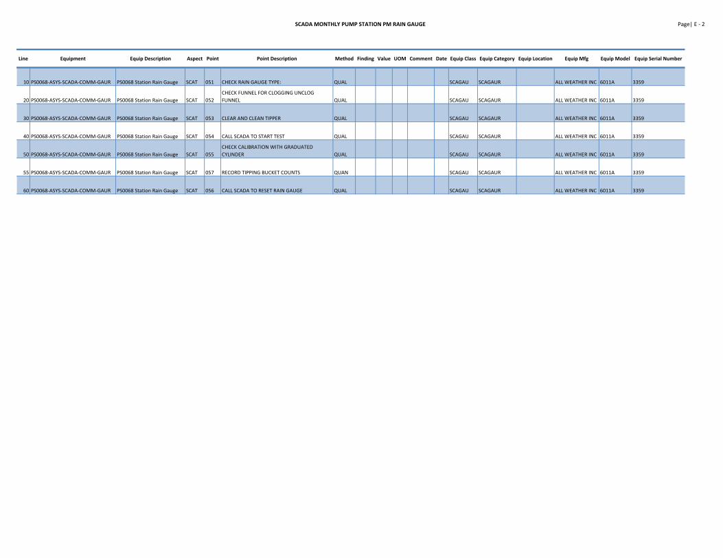
SCADA MONTHLY PUMP STATION PM RAIN GAUGE Page| E ‐ 2
Line Equipment Equip Description Aspect Point Point Description Method Finding Value UOM Comment Date Equip Class Equip Category Equip Location Equip Mfg Equip Model Equip Serial Number
10 PS0068‐ASYS‐SCADA‐COMM‐GAUR PS0068 Station Rain Gauge SCAT 051 CHECK RAIN GAUGE TYPE: QUAL SCAGAU SCAGAUR ALL WEATHER INC 6011A 3359
20 PS0068‐ASYS‐SCADA‐COMM‐GAUR PS0068 Station Rain Gauge SCAT 052
CHECK FUNNEL FOR CLOGGING UNCLOG
FUNNEL QUAL SCAGAU SCAGAUR ALL WEATHER INC 6011A 3359
30 PS0068‐ASYS‐SCADA‐COMM‐GAUR PS0068 Station Rain Gauge SCAT 053 CLEAR AND CLEAN TIPPER QUAL SCAGAU SCAGAUR ALL WEATHER INC 6011A 3359
40 PS0068‐ASYS‐SCADA‐COMM‐GAUR PS0068 Station Rain Gauge SCAT 054 CALL SCADA TO START TEST QUAL SCAGAU SCAGAUR ALL WEATHER INC 6011A 3359
50 PS0068‐ASYS‐SCADA‐COMM‐GAUR PS0068 Station Rain Gauge SCAT 055
CHECK CALIBRATION WITH GRADUATED
CYLINDER QUAL SCAGAU SCAGAUR ALL WEATHER INC 6011A 3359
55 PS0068‐ASYS‐SCADA‐COMM‐GAUR PS0068 Station Rain Gauge SCAT 057 RECORD TIPPING BUCKET COUNTS QUAN SCAGAU SCAGAUR ALL WEATHER INC 6011A 3359
60 PS0068‐ASYS‐SCADA‐COMM‐GAUR PS0068 Station Rain Gauge SCAT 056 CALL SCADA TO RESET RAIN GAUGE QUAL SCAGAU SCAGAUR ALL WEATHER INC 6011A 3359
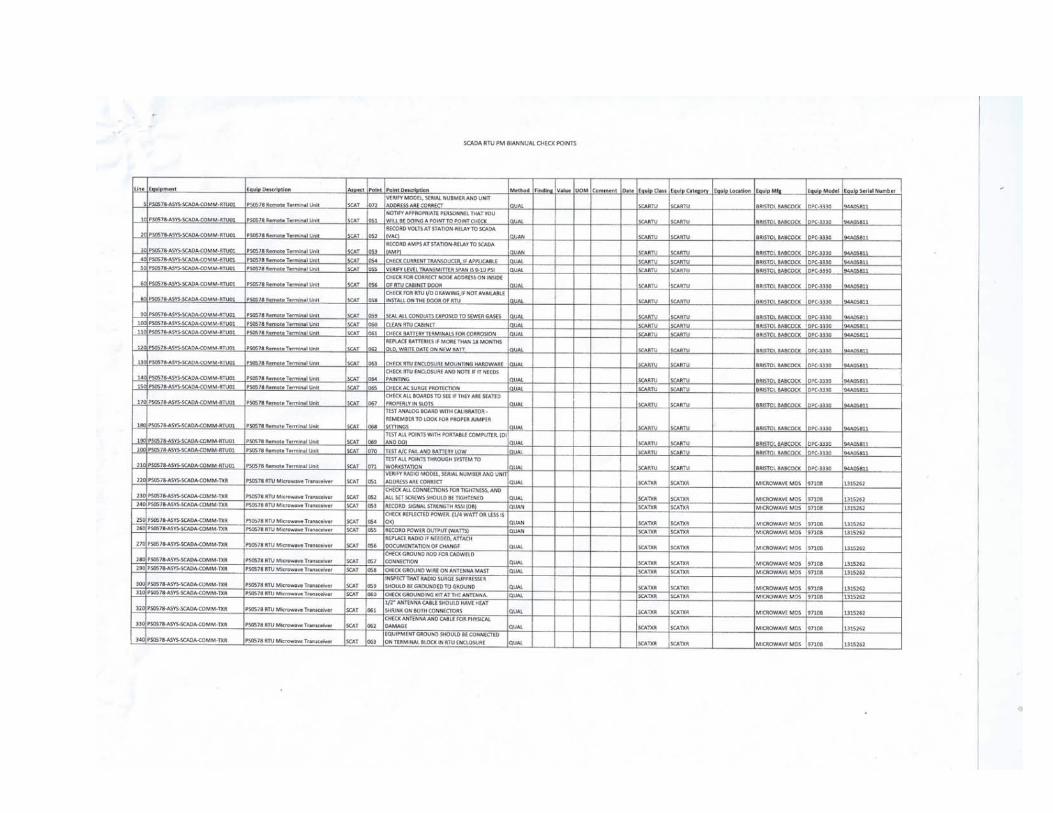

THIS PAGE LEFT INTENTIONALLY BLANK
APPENDIX F
Work Order Status Report EAMS Screen Shot Examples

THIS PAGE LEFT INTENTIONALLY BLANK
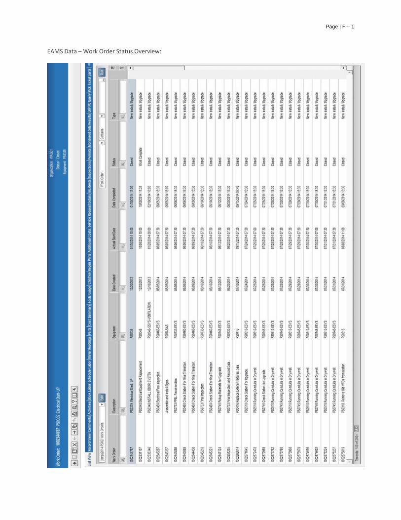
Page | F – 1
EAMS Data – Work Order Status Overview:

THIS PAGE LEFT INTENTIONALLY BLANK
APPENDIX G
Critical Spare Parts and Equipment List

THIS PAGE LEFT INTENTIONALLY BLANK
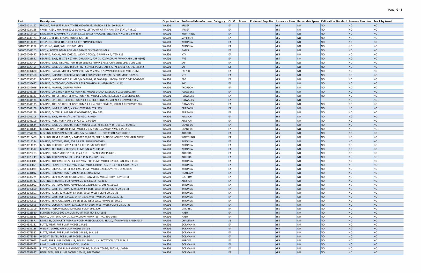
Page| G ‐ 1
Part Description Organization Preferred Manufacturer Category OUM Buyer Preferred Supplier Insurance Item Repairable Spare Calibration Standard Prevene Reorders Track by Asset2520050024167 U‐JOINT, FOR LEFT PUMP AT 4TH AND 9TH ST. STATIONS, F.M. 20 PUMP WASD1 SPICER EA YES NO NO NO NO
2520050024168 CROSS, ASSY., W/CAP NEEDLE BEARING, LEFT PUMP AT 4TH AND 9TH STAT., F.M. 20 WASD1 SPICER EA YES NO NO NO NO
2815050013490 RING, ITEM 3, PUMP S/N 1543846, SIZE 20‐LCS‐4 VOLUTE, ENGINE S/N V03451, SW #5 M WASD1 WORTHING EA YES NO NO NO NO
2815050033473 PUMP, LUBE OIL, ENGINE MODEL 12GT2B WASD1 SUPERIOR EA YES NO NO NO NO
3010050014239 COUPLING, DRIVE HALF, FOR B.J. EFF PUMP 806E1073 WASD1 BYRON JA EA YES NO NO NO NO
3010050014272 COUPLING, #401, WELL FIELD PUMPS WASD1 BYRON JA EA YES NO NO NO NO
3030050041265 BELT, V, POWER BAND, FOR MAG DRIVES CENTRATE PUMPS WASD1 GATES EA YES NO NO NO NO
3110050008437 BEARING, RADIAL, P/N 1003201, WEMCO TORQUE PUMP 4X 4, ITEM #23 WASD1 NTN EA YES NO NO NO NO
3110050025541 BEARING, BALL, 35 X 72 X 27MM, DRIVE END, FOR CL‐302 VACUUM PUMP(NASH UBB‐0305) WASD1 FAG EA YES NO NO NO NO
3110050029494 BEARING, BALL, INBOARD, FOR HIGH SERVICE PUMP, ( ALLIS‐CHALMERS CP811‐005‐733) WASD1 SKF EA YES NO NO NO NO
3110050029495 BEARING, BALL, OUTBOARD, FOR HIGH SERVICE PUMP, (ALLIS‐CHAL CP811‐423‐733),SET=2 WASD1 SKF ST YES NO NO NO NO
3110050032880 BEARING, RADIAL, MORRIS PUMP 2RX, S/N M‐22155‐57 (P/N 9001130300, MRC 313M) WASD1 FAFNIR EA YES NO NO NO NO
3110050033350 BEARING, INBOARD, CHLORINE BOOSTER PUMP SPLIT CASE(ALLIS‐CHALMERS 3‐026‐3) WASD1 NTN EA YES NO NO NO NO
3110050034581 BEARING, INBOARD 6332, PUMP S/N 64869‐1, SZ 36X24L(ALLIS‐CHALMERS 52‐129‐364‐001 WASD1 FAG EA YES NO NO NO NO
3110050035677 BEARING, OUTBOARD, CHEMICAL RECIRCULATION PUMP(DURCO 1K121) WASD1 SKK EA YES NO NO NO NO
3110050039046 BEARING, MARINE, COLUMN PUMP WASD1 THORDON EA YES NO NO NO NO
3110050041126 BEARING, LINE, HIGH SERVICE PUMP #5, MODEL 24LNC42, SERIAL # 0109MS001386 WASD1 FLOWSERV EA YES NO NO NO NO
3110050041127 BEARING, THRUST, HIGH SERVICE PUMP #5, MODEL 24LNC42, SERIAL # 0109MS001386 WASD1 FLOWSERV EA YES NO NO NO NO
3110050041134 BEARING, LINE, HIGH SERVICE PUMP # 3 & 4, SIZE 16LNC‐28, SERIAL # 0109MS001385 WASD1 FLOWSERV EA YES NO NO NO
3110050041135 BEARING, THRUST, HIGH SERVICE PUMP # 3 & 4, SIZE 16LNC‐28, SERIAL # 0109MS001385 WASD1 FLOWSERV EA YES NO NO NO NO
3110050041198 BEARING, INNER, PUMP S/N K3W1070757‐0, STA. 595 WASD1 FAIRBANK EA YES NO NO NO NO
3110050041199 BEARING, OUTER, PUMP S/N K3W1070757‐0, STA. 595 WASD1 FAIRBANK EA YES NO NO NO NO
3110050041208 BEARING, BALL, PUMP S/N 1‐64723‐01‐2, PS 690 WASD1 ALLIS‐CH EA YES NO NO NO NO
3110050041209 BEARING, ROLL, PUMP S/N 1‐64723‐01‐1, PS 690 WASD1 ALLIS‐CH EA YES NO NO NO NO
3110050041644 BEARING, BALL, OUTBOARD, PUMP MODEL 7196, 4x4x12, S/N DP‐759171, PS 0510 WASD1 CRANE DE EA YES NO NO NO NO
3110050041645 BERING, BALL, INBOARD, PUMP MODEL 7196, 4x4x12, S/N DP‐759171, PS 0510 WASD1 CRANE DE EA YES NO NO NO NO
3120011557270 BUSHING, FOR PUMP MODEL 413, S/N 84‐1207‐1, L.H. ROTATION, SIZE 6X8X15 WASD1 AURORA EA YES NO NO NO NO
3120050013489 BUSHING, ITEM 3, PUMP S/N 1413987,88,89,90, SIZE 16‐LNC‐35 VOLUTE, SDR MAIN PUMP WASD1 WORTHING EA YES NO NO NO NO
3120050014234 BEARING, BOTTOM, #104, FOR B.J. EFF. PUMP 806E1073 WASD1 BYRON JA EA YES NO NO NO NO
3120050014235 BUSHING, THROTTLE, #232, FOR B.J. EFF. PUMP 806E1073 WASD1 BYRON JA EA YES NO NO NO NO
3120050014317 BEARING, TEE, BYRON JACKSON PUMP S/N #279‐740/45 WASD1 BYRON JA EA YES NO NO NO NO
3120050025203 BEARING, PUMP MODELS 114, 115 & 116 FAFNIR SME15K/COL WASD1 AURORA EA YES NO NO NO NO
3120050025249 BUSHING, FOR PUMP MODELS 114, 115 & 116 TYPE F4S WASD1 AURORA EA YES NO NO NO NO
3120050030045 BEARING, TOP CASE, 3 1/2 X 4 X 2 7/16 , FOR PUMP MODEL 32RXL1, S/N 816‐E‐1103, WASD1 BYRON JA EA YES NO NO NO NO
3120050030051 BEARING, PLAIN, 3 1/2 X 2 7/16, PUMP MODEL32RXL1, S/N 816‐E‐1103, SWWF 25‐28 WASD1 BYRON JA EA YES NO NO NO NO
3120050030081 BEARING, BRONZE, TOP SERIES CASE, PUMP MODEL 32RXL, S/N 771E‐0121/0126 WASD1 BYRON JA EA YES NO NO NO NO
3120050031012 BEARING, INBOARD, PUMP S/N 251153, 14000 GPM WASD1 TRANSAM‐ EA YES NO NO NO NO
3120050033224 BEARING, SCREW, PUMP MODEL 28TLO, S/N26142, WELLS1‐4 (PATT. #A1610) WASD1 U.S. PUM EA YES NO NO NO NO
3120050034432 BUSHING, THROTTLE, FOR PUMP SIZE 10 X 8 X 14 ‐ U1314B WASD1 ALLIS‐CH EA YES NO NO NO NO
3120050039092 BEARING, BOTTOM, #104, PUMP MODEL 32RXL2STG, S/N 781E0173 WASD1 BYRON JA EA YES NO NO NO NO
3120050040890 BEARING, CASE, BOTTOM, 32RXL1, 94‐ER‐1616, WEST WELL PUMPS 29, 30 ,31 WASD1 BYRON JA EA YES NO NO NO NO
3120050040891 BEARING, JUMP, 32RXL1, 94‐ER‐1616, WEST WELL PUMPS 29, 30 ,31 WASD1 BYRON JA EA YES NO NO NO NO
3120050040892 BEARING, CASE, TOP, 32RXL1, 94‐ER‐1616, WEST WELL PUMPS 29, 30 ,31 WASD1 BYRON JA EA YES NO NO NO NO
3120050040893 BEARING, TENSION, 32RXL1, 94‐ER‐1616, WEST WELL PUMPS 29, 30 ,31 WASD1 BYRON JA EA YES NO NO NO NO
3120050040895 BEARING, COLUMN, PLAIN, 32RXL1, 94‐ER‐1616, WEST WELL PUMPS 29, 30 ,31 WASD1 BYRON JA EA YES NO NO NO NO
3130050012309 BEARING, PILLOW BLOCK (MARLOW PUMP 2951200) WASD1 LINK‐BEL EA YES NO NO NO NO
4310050025520 SLINGER, FOR CL‐302 VACUUM PUMP TEST NO. 83U‐1688 WASD1 NASH EA YES NO NO NO NO
4310050025523 GLAND, LANTERN, FOR CL‐302 VACUUM PUMP TEST NO. 83U‐1688 WASD1 NASH EA YES NO NO NO NO
4310050033571 RING, SET, COMPLETE PUMP, AIR COMPRESSOR MODEL BRA20, S/N R70A5983 AND 5984 WASD1 CHAMPAIR ST YES NO NO NO NO
4320003535181 PLATE, WEAR, FOR PUMP MODEL 13A2‐B WASD1 GORMAN‐R EA YES NO NO NO NO
4320003535188 WEIGHT, LARGE, FOR PUMP MODEL 14A2‐B WASD1 GORMAN‐R EA YES NO NO NO NO
4320004078522 PLATE, WEAR, FOR PUMP MODEL 14A2‐B, 14A11‐B WASD1 GORMAN‐R EA YES NO NO NO NO
4320004278586 WEIGHT, SMALL, FOR PUMP MODEL 14A2‐B WASD1 GORMAN‐R EA YES NO NO NO NO
4320004673065 SHAFT, FOR PUMP MODEL 413, S/N 84‐12607‐1, L.H. ROTATION, SIZE 6X8X15 WASD1 AURORA EA YES NO NO NO NO
4320004807397 RING, SLINGER, FOR PUMP MODEL 14A2‐B WASD1 GORMAN‐R EA YES NO NO NO NO
4320004963679 PLATE, COVER, FOR PUMP MODELS T3A3‐B, T4A3‐B, T6A3‐B, T8A3‐B, 14A2‐B WASD1 GORMAN‐R EA YES NO NO NO NO
4320007792837 LINER, SEAL, FOR PUMP MODEL 12D‐13, S/N 756206 WASD1 GORMAN‐R EA YES NO NO NO NO
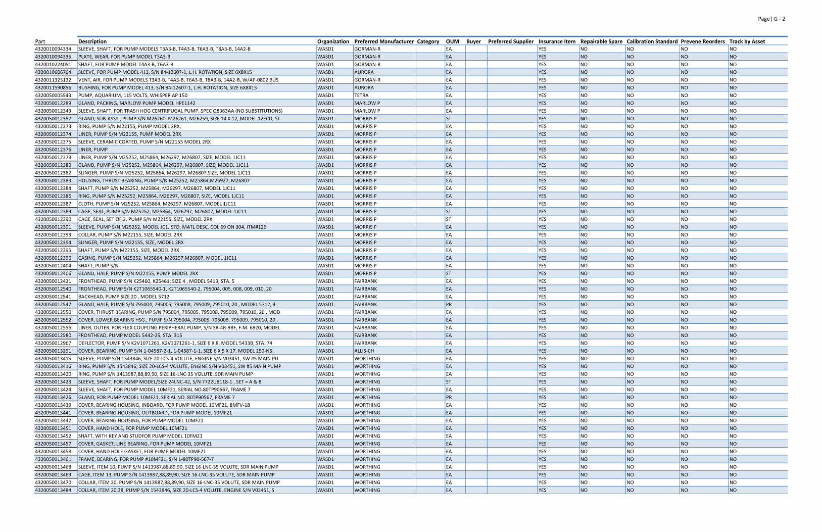
Page| G ‐ 2
Part Description Organization Preferred Manufacturer Category OUM Buyer Preferred Supplier Insurance Item Repairable Spare Calibration Standard Prevene Reorders Track by Asset4320010094334 SLEEVE, SHAFT, FOR PUMP MODELS T3A3‐B, T4A3‐B, T6A3‐B, T8A3‐B, 14A2‐B WASD1 GORMAN‐R EA YES NO NO NO NO
4320010094335 PLATE, WEAR, FOR PUMP MODEL T3A3‐B WASD1 GORMAN‐R EA YES NO NO NO NO
4320010224051 SHAFT, FOR PUMP MODEL T4A3‐B, T6A3‐B WASD1 GORMAN‐R EA YES NO NO NO NO
4320010606704 SLEEVE, FOR PUMP MODEL 413, S/N 84‐12607‐1, L.H. ROTATION, SIZE 6X8X15 WASD1 AURORA EA YES NO NO NO NO
4320011323132 VENT, AIR, FOR PUMP MODELS T3A3‐B, T4A3‐B, T6A3‐B, T8A3‐B, 14A2‐B, W/AP‐0802 BUS WASD1 GORMAN‐R EA YES NO NO NO NO
4320011590856 BUSHING, FOR PUMP MODEL 413, S/N 84‐12607‐1, L.H. ROTATION, SIZE 6X8X15 WASD1 AURORA EA YES NO NO NO NO
4320050005543 PUMP, AQUARIUM, 115 VOLTS, WHISPER AP 150 WASD1 TETRA EA YES NO NO NO NO
4320050012289 GLAND, PACKING, MARLOW PUMP MODEL HPE1142 WASD1 MARLOW P EA YES NO NO NO NO
4320050012343 SLEEVE, SHAFT, FOR TRASH HOG CENTRIFUGAL PUMP, SPEC Q8363AA (NO SUBSTITUTIONS) WASD1 MARLOW P EA YES NO NO NO NO
4320050012357 GLAND, SUB‐ASSY., PUMP S/N M26260, M26261, M26259, SIZE 14 X 12, MODEL 12ECD, ST WASD1 MORRIS P ST YES NO NO NO NO
4320050012373 RING, PUMP S/N M22155, PUMP MODEL 2RX, WASD1 MORRIS P EA YES NO NO NO NO
4320050012374 LINER, PUMP S/N M22155, PUMP MODEL 2RX WASD1 MORRIS P EA YES NO NO NO NO
4320050012375 SLEEVE, CERAMIC COATED, PUMP S/N M22155 MODEL 2RX WASD1 MORRIS P EA YES NO NO NO NO
4320050012376 LINER, PUMP WASD1 MORRIS P EA YES NO NO NO NO
4320050012379 LINER, PUMP S/N M25252, M25864, M26297, M26807, SIZE, MODEL 1JC11 WASD1 MORRIS P EA YES NO NO NO NO
4320050012380 GLAND, PUMP S/N M25252, M25864, M26297, M26807, SIZE, MODEL 1JC11 WASD1 MORRIS P EA YES NO NO NO NO
4320050012382 SLINGER, PUMP S/N M25252, M25864, M26297, M26807,SIZE, MODEL 1JC11 WASD1 MORRIS P EA YES NO NO NO NO
4320050012383 HOUSING, THRUST BEARING, PUMP S/N M25252, M25864,M26927, M26807 WASD1 MORRIS P EA YES NO NO NO NO
4320050012384 SHAFT, PUMP S/N M25252, M25864, M26297, M26807, MODEL 1JC11 WASD1 MORRIS P EA YES NO NO NO NO
4320050012386 RING, PUMP S/N M25252, M25864, M26297, M26807, SIZE, MODEL 1JC11 WASD1 MORRIS P EA YES NO NO NO NO
4320050012387 CLOTH, PUMP S/N M25252, M25864, M26297, M26807, MODEL 1JC11 WASD1 MORRIS P EA YES NO NO NO NO
4320050012389 CAGE, SEAL, PUMP S/N M25252, M25864, M26297, M26807, MODEL 1JC11 WASD1 MORRIS P ST YES NO NO NO NO
4320050012390 CAGE, SEAL, SET OF 2, PUMP S/N M22155, SIZE, MODEL 2RX WASD1 MORRIS P ST YES NO NO NO NO
4320050012391 SLEEVE, PUMP S/N M25252, MODEL JC1J STD. MATL DESC. COL 69 ON 304, ITM#126 WASD1 MORRIS P EA YES NO NO NO NO
4320050012393 COLLAR, PUMP S/N M22155, SIZE, MODEL 2RX WASD1 MORRIS P EA YES NO NO NO NO
4320050012394 SLINGER, PUMP S/N M22155, SIZE, MODEL 2RX WASD1 MORRIS P EA YES NO NO NO NO
4320050012395 SHAFT, PUMP S/N M22155, SIZE, MODEL 2RX WASD1 MORRIS P EA YES NO NO NO NO
4320050012396 CASING, PUMP S/N M25252, M25864, M26297,M26807, MODEL 1JC11 WASD1 MORRIS P EA YES NO NO NO NO
4320050012404 SHAFT, PUMP S/N WASD1 MORRIS P EA YES NO NO NO NO
4320050012406 GLAND, HALF, PUMP S/N M22155, PUMP MODEL 2RX WASD1 MORRIS P ST YES NO NO NO NO
4320050012431 FRONTHEAD, PUMP S/N K25460, K25461, SIZE 4 , MODEL 5413, STA. 5 WASD1 FAIRBANK EA YES NO NO NO NO
4320050012540 FRONTHEAD, PUMP S/N K2T1065540‐1, K2T1065540‐2, 795004, 005, 008, 009, 010, 20 WASD1 FAIRBANK EA YES NO NO NO NO
4320050012541 BACKHEAD, PUMP SIZE 20 , MODEL 5712 WASD1 FAIRBANK EA YES NO NO NO NO
4320050012547 GLAND, HALF, PUMP S/N 795004, 795005, 795008, 795009, 795010, 20 , MODEL 5712, 4 WASD1 FAIRBANK PR YES NO NO NO NO
4320050012550 COVER, THRUST BEARING, PUMP S/N 795004, 795005, 795008, 795009, 795010, 20 , MOD WASD1 FAIRBANK EA YES NO NO NO NO
4320050012552 COVER, LOWER BEARING HSG., PUMP S/N 795004, 795005, 795008, 795009, 795010, 20 , WASD1 FAIRBANK EA YES NO NO NO NO
4320050012556 LINER, OUTER, FOR FLEX COUPLING PERIPHERAL PUMP, S/N SR‐4R‐9BF, F.M. 6820, MODEL WASD1 FAIRBANK EA YES NO NO NO NO
4320050012580 FRONTHEAD, PUMP MODEL 5442‐25, STA. 315 WASD1 FAIRBANK EA YES NO NO NO NO
4320050012967 DEFLECTOR, PUMP S/N K2V1071261, K2V1071261‐1, SIZE 6 X 8, MODEL 5433B, STA. 74 WASD1 FAIRBANK EA YES NO NO NO NO
4320050013291 COVER, BEARING, PUMP S/N 1‐04587‐2‐1, 1‐04587‐1‐1, SIZE 6 X 5 X 17, MODEL 250‐NS WASD1 ALLIS‐CH EA YES NO NO NO NO
4320050013415 SLEEVE, PUMP S/N 1543846, SIZE 20‐LCS‐4 VOLUTE, ENGINE S/N V03451, SW #5 MAIN PU WASD1 WORTHING EA YES NO NO NO NO
4320050013416 RING, PUMP S/N 1543846, SIZE 20‐LCS‐4 VOLUTE, ENGINE S/N V03451, SW #5 MAIN PUMP WASD1 WORTHING EA YES NO NO NO NO
4320050013420 RING, PUMP S/N 1413987,88,89,90, SIZE 16‐LNC‐35 VOLUTE, SDR MAIN PUMP WASD1 WORTHING EA YES NO NO NO NO
4320050013423 SLEEVE, SHAFT, FOR PUMP MODEL/SIZE 24LNC‐42, S/N 7722U8118‐1 , SET = A & B WASD1 WORTHING ST YES NO NO NO NO
4320050013424 SLEEVE, SHAFT, FOR PUMP MODEL 10MF21, SERIAL NO.80TP90567, FRAME 7 WASD1 WORTHING EA YES NO NO NO NO
4320050013426 GLAND, FOR PUMP MODEL 10MF21, SERIAL NO. 80TP90567, FRAME 7 WASD1 WORTHING PR YES NO NO NO NO
4320050013439 COVER, BEARING HOUSING, INBOARD, FOR PUMP MODEL 10MF21, 8MFV‐18 WASD1 WORTHING EA YES NO NO NO NO
4320050013441 COVER, BEARING HOUSING, OUTBOARD, FOR PUMP MODEL 10MF21 WASD1 WORTHING EA YES NO NO NO NO
4320050013442 COVER, BEARING HOUSING, FOR PUMP MODEL 10MF21 WASD1 WORTHING EA YES NO NO NO NO
4320050013451 COVER, HAND HOLE, FOR PUMP MODEL 10MF21 WASD1 WORTHING EA YES NO NO NO NO
4320050013452 SHAFT, WITH KEY AND STUDFOR PUMP M0DEL 10FM21 WASD1 WORTHING EA YES NO NO NO NO
4320050013457 COVER, GASKET, LINE BEARING, FOR PUMP MODEL 10MF21 WASD1 WORTHING EA YES NO NO NO NO
4320050013458 COVER, HAND HOLE GASKET, FOR PUMP MODEL 10MF21 WASD1 WORTHING EA YES NO NO NO NO
4320050013461 FRAME, BEARING, FOR PUMP #10MF21, S/N 1‐80TP90‐567‐7 WASD1 WORTHING EA YES NO NO NO NO
4320050013468 SLEEVE, ITEM 10, PUMP S/N 1413987,88,89,90, SIZE 16‐LNC‐35 VOLUTE, SDR MAIN PUMP WASD1 WORTHING EA YES NO NO NO NO
4320050013469 CAGE, ITEM 13, PUMP S/N 1413987,88,89,90, SIZE 16‐LNC‐35 VOLUTE, SDR MAIN PUMP WASD1 WORTHING EA YES NO NO NO NO
4320050013470 COLLAR, ITEM 20, PUMP S/N 1413987,88,89,90, SIZE 16‐LNC‐35 VOLUTE, SDR MAIN PUMP WASD1 WORTHING EA YES NO NO NO NO
4320050013484 COLLAR, ITEM 20,38, PUMP S/N 1543846, SIZE 20‐LCS‐4 VOLUTE, ENGINE S/N V03451, S WASD1 WORTHING EA YES NO NO NO NO
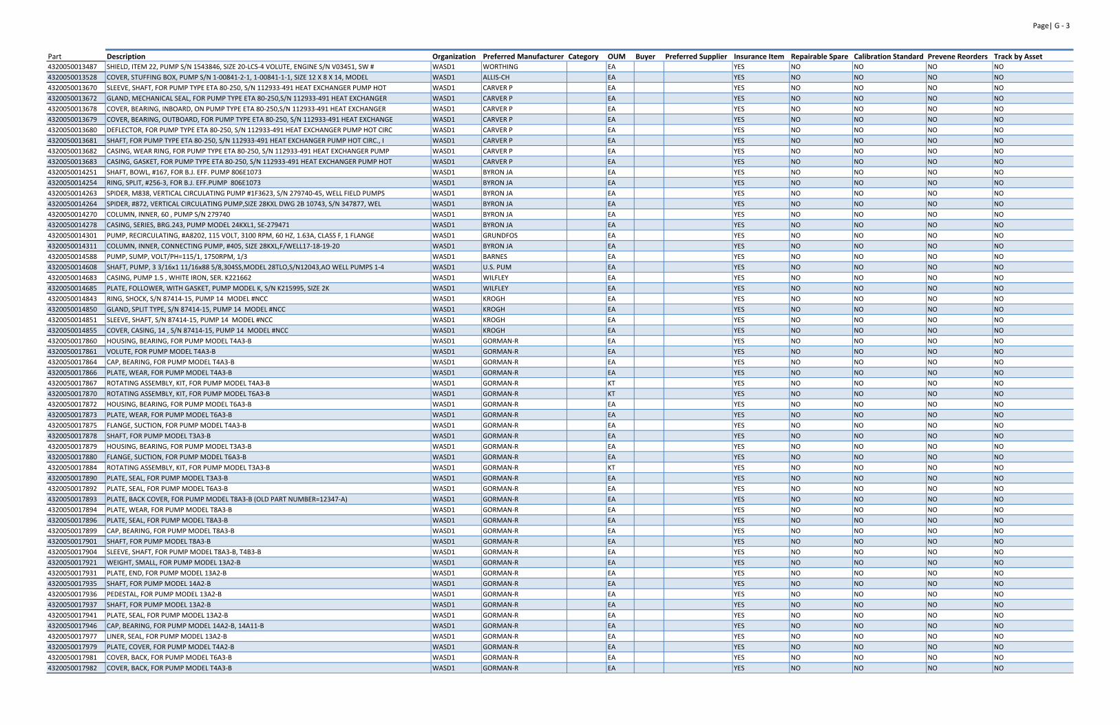
Page| G ‐ 3
Part Description Organization Preferred Manufacturer Category OUM Buyer Preferred Supplier Insurance Item Repairable Spare Calibration Standard Prevene Reorders Track by Asset4320050013487 SHIELD, ITEM 22, PUMP S/N 1543846, SIZE 20‐LCS‐4 VOLUTE, ENGINE S/N V03451, SW # WASD1 WORTHING EA YES NO NO NO NO
4320050013528 COVER, STUFFING BOX, PUMP S/N 1‐00841‐2‐1, 1‐00841‐1‐1, SIZE 12 X 8 X 14, MODEL WASD1 ALLIS‐CH EA YES NO NO NO NO
4320050013670 SLEEVE, SHAFT, FOR PUMP TYPE ETA 80‐250, S/N 112933‐491 HEAT EXCHANGER PUMP HOT WASD1 CARVER P EA YES NO NO NO NO
4320050013672 GLAND, MECHANICAL SEAL, FOR PUMP TYPE ETA 80‐250,S/N 112933‐491 HEAT EXCHANGER WASD1 CARVER P EA YES NO NO NO NO
4320050013678 COVER, BEARING, INBOARD, ON PUMP TYPE ETA 80‐250,S/N 112933‐491 HEAT EXCHANGER WASD1 CARVER P EA YES NO NO NO NO
4320050013679 COVER, BEARING, OUTBOARD, FOR PUMP TYPE ETA 80‐250, S/N 112933‐491 HEAT EXCHANGE WASD1 CARVER P EA YES NO NO NO NO
4320050013680 DEFLECTOR, FOR PUMP TYPE ETA 80‐250, S/N 112933‐491 HEAT EXCHANGER PUMP HOT CIRC WASD1 CARVER P EA YES NO NO NO NO
4320050013681 SHAFT, FOR PUMP TYPE ETA 80‐250, S/N 112933‐491 HEAT EXCHANGER PUMP HOT CIRC., I WASD1 CARVER P EA YES NO NO NO NO
4320050013682 CASING, WEAR RING, FOR PUMP TYPE ETA 80‐250, S/N 112933‐491 HEAT EXCHANGER PUMP WASD1 CARVER P EA YES NO NO NO NO
4320050013683 CASING, GASKET, FOR PUMP TYPE ETA 80‐250, S/N 112933‐491 HEAT EXCHANGER PUMP HOT WASD1 CARVER P EA YES NO NO NO NO
4320050014251 SHAFT, BOWL, #167, FOR B.J. EFF. PUMP 806E1073 WASD1 BYRON JA EA YES NO NO NO NO
4320050014254 RING, SPLIT, #256‐3, FOR B.J. EFF.PUMP 806E1073 WASD1 BYRON JA EA YES NO NO NO NO
4320050014263 SPIDER, M838, VERTICAL CIRCULATING PUMP #1F3623, S/N 279740‐45, WELL FIELD PUMPS WASD1 BYRON JA EA YES NO NO NO NO
4320050014264 SPIDER, #872, VERTICAL CIRCULATING PUMP,SIZE 28KXL DWG 2B 10743, S/N 347877, WEL WASD1 BYRON JA EA YES NO NO NO NO
4320050014270 COLUMN, INNER, 60 , PUMP S/N 279740 WASD1 BYRON JA EA YES NO NO NO NO
4320050014278 CASING, SERIES, BRG.243, PUMP MODEL 24KXL1, SE‐279471 WASD1 BYRON JA EA YES NO NO NO NO
4320050014301 PUMP, RECIRCULATING, #A8202, 115 VOLT, 3100 RPM, 60 HZ, 1.63A, CLASS F, 1 FLANGE WASD1 GRUNDFOS EA YES NO NO NO NO
4320050014311 COLUMN, INNER, CONNECTING PUMP, #405, SIZE 28KXL,F/WELL17‐18‐19‐20 WASD1 BYRON JA EA YES NO NO NO NO
4320050014588 PUMP, SUMP, VOLT/PH=115/1, 1750RPM, 1/3 WASD1 BARNES EA YES NO NO NO NO
4320050014608 SHAFT, PUMP, 3 3/16x1 11/16x88 5/8,304SS,MODEL 28TLO,S/N12043,AO WELL PUMPS 1‐4 WASD1 U.S. PUM EA YES NO NO NO NO
4320050014683 CASING, PUMP 1.5 , WHITE IRON, SER. K221662 WASD1 WILFLEY EA YES NO NO NO NO
4320050014685 PLATE, FOLLOWER, WITH GASKET, PUMP MODEL K, S/N K215995, SIZE 2K WASD1 WILFLEY EA YES NO NO NO NO
4320050014843 RING, SHOCK, S/N 87414‐15, PUMP 14 MODEL #NCC WASD1 KROGH EA YES NO NO NO NO
4320050014850 GLAND, SPLIT TYPE, S/N 87414‐15, PUMP 14 MODEL #NCC WASD1 KROGH EA YES NO NO NO NO
4320050014851 SLEEVE, SHAFT, S/N 87414‐15, PUMP 14 MODEL #NCC WASD1 KROGH EA YES NO NO NO NO
4320050014855 COVER, CASING, 14 , S/N 87414‐15, PUMP 14 MODEL #NCC WASD1 KROGH EA YES NO NO NO NO
4320050017860 HOUSING, BEARING, FOR PUMP MODEL T4A3‐B WASD1 GORMAN‐R EA YES NO NO NO NO
4320050017861 VOLUTE, FOR PUMP MODEL T4A3‐B WASD1 GORMAN‐R EA YES NO NO NO NO
4320050017864 CAP, BEARING, FOR PUMP MODEL T4A3‐B WASD1 GORMAN‐R EA YES NO NO NO NO
4320050017866 PLATE, WEAR, FOR PUMP MODEL T4A3‐B WASD1 GORMAN‐R EA YES NO NO NO NO
4320050017867 ROTATING ASSEMBLY, KIT, FOR PUMP MODEL T4A3‐B WASD1 GORMAN‐R KT YES NO NO NO NO
4320050017870 ROTATING ASSEMBLY, KIT, FOR PUMP MODEL T6A3‐B WASD1 GORMAN‐R KT YES NO NO NO NO
4320050017872 HOUSING, BEARING, FOR PUMP MODEL T6A3‐B WASD1 GORMAN‐R EA YES NO NO NO NO
4320050017873 PLATE, WEAR, FOR PUMP MODEL T6A3‐B WASD1 GORMAN‐R EA YES NO NO NO NO
4320050017875 FLANGE, SUCTION, FOR PUMP MODEL T4A3‐B WASD1 GORMAN‐R EA YES NO NO NO NO
4320050017878 SHAFT, FOR PUMP MODEL T3A3‐B WASD1 GORMAN‐R EA YES NO NO NO NO
4320050017879 HOUSING, BEARING, FOR PUMP MODEL T3A3‐B WASD1 GORMAN‐R EA YES NO NO NO NO
4320050017880 FLANGE, SUCTION, FOR PUMP MODEL T6A3‐B WASD1 GORMAN‐R EA YES NO NO NO NO
4320050017884 ROTATING ASSEMBLY, KIT, FOR PUMP MODEL T3A3‐B WASD1 GORMAN‐R KT YES NO NO NO NO
4320050017890 PLATE, SEAL, FOR PUMP MODEL T3A3‐B WASD1 GORMAN‐R EA YES NO NO NO NO
4320050017892 PLATE, SEAL, FOR PUMP MODEL T6A3‐B WASD1 GORMAN‐R EA YES NO NO NO NO
4320050017893 PLATE, BACK COVER, FOR PUMP MODEL T8A3‐B (OLD PART NUMBER=12347‐A) WASD1 GORMAN‐R EA YES NO NO NO NO
4320050017894 PLATE, WEAR, FOR PUMP MODEL T8A3‐B WASD1 GORMAN‐R EA YES NO NO NO NO
4320050017896 PLATE, SEAL, FOR PUMP MODEL T8A3‐B WASD1 GORMAN‐R EA YES NO NO NO NO
4320050017899 CAP, BEARING, FOR PUMP MODEL T8A3‐B WASD1 GORMAN‐R EA YES NO NO NO NO
4320050017901 SHAFT, FOR PUMP MODEL T8A3‐B WASD1 GORMAN‐R EA YES NO NO NO NO
4320050017904 SLEEVE, SHAFT, FOR PUMP MODEL T8A3‐B, T4B3‐B WASD1 GORMAN‐R EA YES NO NO NO NO
4320050017921 WEIGHT, SMALL, FOR PUMP MODEL 13A2‐B WASD1 GORMAN‐R EA YES NO NO NO NO
4320050017931 PLATE, END, FOR PUMP MODEL 13A2‐B WASD1 GORMAN‐R EA YES NO NO NO NO
4320050017935 SHAFT, FOR PUMP MODEL 14A2‐B WASD1 GORMAN‐R EA YES NO NO NO NO
4320050017936 PEDESTAL, FOR PUMP MODEL 13A2‐B WASD1 GORMAN‐R EA YES NO NO NO NO
4320050017937 SHAFT, FOR PUMP MODEL 13A2‐B WASD1 GORMAN‐R EA YES NO NO NO NO
4320050017941 PLATE, SEAL, FOR PUMP MODEL 13A2‐B WASD1 GORMAN‐R EA YES NO NO NO NO
4320050017946 CAP, BEARING, FOR PUMP MODEL 14A2‐B, 14A11‐B WASD1 GORMAN‐R EA YES NO NO NO NO
4320050017977 LINER, SEAL, FOR PUMP MODEL 13A2‐B WASD1 GORMAN‐R EA YES NO NO NO NO
4320050017979 PLATE, COVER, FOR PUMP MODEL T4A2‐B WASD1 GORMAN‐R EA YES NO NO NO NO
4320050017981 COVER, BACK, FOR PUMP MODEL T6A3‐B WASD1 GORMAN‐R EA YES NO NO NO NO
4320050017982 COVER, BACK, FOR PUMP MODEL T4A3‐B WASD1 GORMAN‐R EA YES NO NO NO NO
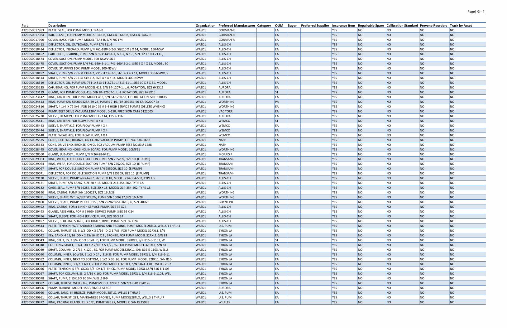
Page| G ‐ 4
Part Description Organization Preferred Manufacturer Category OUM Buyer Preferred Supplier Insurance Item Repairable Spare Calibration Standard Prevene Reorders Track by Asset4320050017983 PLATE, SEAL, FOR PUMP MODEL T4A3‐B WASD1 GORMAN‐R EA YES NO NO NO NO
4320050017984 BAR, CLAMP, FOR PUMP MODELS T3A3‐B, T4A3‐B, T6A3‐B, T8A3‐B, 14A2‐B WASD1 GORMAN‐R EA YES NO NO NO NO
4320050017990 COVER, BACK, FOR PUMP MODEL T3A3‐B, S/N 707174 WASD1 GORMAN‐R EA YES NO NO NO NO
4320050018413 DEFLECTOR, OIL, OUTBOARD, PUMP S/N 811‐3 WASD1 ALLIS‐CH EA YES NO NO NO NO
4320050018414 DEFLECTOR, INBOARD, PUMP S/N 761‐18845‐2‐3, SIZE10 X 8 X 14, MODEL 150‐NSW WASD1 ALLIS‐CH EA YES NO NO NO NO
4320050018452 CARTRIDGE, BEARING, PUMP S/N 801‐35149‐1‐1, & 1‐2, & 1‐3, SIZE 12 X 10 X 21 LC, WASD1 ALLIS‐CH EA YES NO NO NO NO
4320050018474 COVER, SUCTION, PUMP MODEL 300‐NSWV,SIZE WASD1 ALLIS‐CH EA YES NO NO NO NO
4320050018475 COVER, SUCTION, PUMP S/N 741‐16045‐1‐1, 741‐16045‐2‐1, SIZE 6 X 4 X 12, MODEL 30 WASD1 ALLIS‐CH EA YES NO NO NO NO
4320050018477 COVER, STUFFING BOX, PUMP MODEL 300‐NSWV WASD1 ALLIS‐CH EA YES NO NO NO NO
4320050018492 SHAFT, PUMP S/N 791‐31739‐4‐2, 791‐31739‐3‐1, SIZE 4 X 4 X 14, MODEL 300‐NSWV, S WASD1 ALLIS‐CH EA YES NO NO NO NO
4320050018514 SHAFT, PUMP S/N 791‐31739‐4‐2, SIZE 4 X 4 X 14, MODEL 300‐NSWV WASD1 ALLIS‐CH EA YES NO NO NO NO
4320050018519 DEFLECTOR, OIL, PUMP S/N 751‐14813‐11‐2,751‐14813‐11‐1, SIZE 10 X 8 X 21, MODEL WASD1 ALLIS‐CH EA YES NO NO NO NO
4320050023135 CAP, BEARING, FOR PUMP MODEL 413, S/N 84‐1207‐1, L.H. ROTATION, SIZE 6X8X15 WASD1 AURORA EA YES NO NO NO NO
4320050023139 GLAND, FOR PUMP MODEL 413, S/N 84‐12607‐1, L.H. ROTATION, SIZE 6X8X15 WASD1 AURORA ST YES NO NO NO NO
4320050023142 RING, LANTERN, FOR PUMP MODEL 413, S/N 84‐12607‐1, L.H. ROTATION, SIZE 6X8X15 WASD1 AURORA EA YES NO NO NO NO
4320050024813 RING, PUMP S/N 560009428A‐29‐28, PUMPS 7‐10, (1R‐397551‐60‐CR‐902007‐3) WASD1 WORTHING PR YES NO NO NO NO
4320050024816 SHAFT, 4 1/4 X 72 3/4 , FOR 16 LNC 35 # 1‐4 HIGH SERVICE PUMPS (DELETE WHEN 0) WASD1 WORTHING EA YES NO NO NO NO
4320050025064 PUMP, BELT DRIVE VACUUM,120V,MODEL D‐150, PRECISION CAT# 5122005 WASD1 VAC TORR EA YES NO NO NO NO
4320050025220 SLEEVE, ITEM#29, FOR PUMP MODELS 114, 115 & 116 WASD1 AURORA EA YES NO NO NO NO
4320050025441 RING, LANTERN, FOR FLOW PUMP 4 X 4 WASD1 WEMCO ST YES NO NO NO NO
4320050025443 SLEEVE, SHAFT #17, FOR FLOW PUMP 4 X 4 WASD1 WEMCO EA YES NO NO NO NO
4320050025444 SLEEVE, SHAFT #18, FOR FLOW PUMP 4 X 4 WASD1 WEMCO EA YES NO NO NO NO
4320050025448 PLATE, WEAR, #29, FOR FLOW PUMP, 4 X 4 WASD1 WEMCO EA YES NO NO NO NO
4320050025535 CONE, IDLE END, BRONZE, ON CL‐302 VACUUM PUMP TEST NO. 83U‐1688 WASD1 NASH EA YES NO NO NO NO
4320050025543 CONE, DRIVE END, BRONZE, ON CL‐302 VACUUM PUMP TEST NO.83U‐1688 WASD1 NASH EA YES NO NO NO NO
4320050028445 COVER, BEARING HOUSING, INBOARD, FOR PUMP MODEL 10MF21 WASD1 WORTHING EA YES NO NO NO NO
4320050028560 GLAND, SUB‐ASSY., PUMP S/N M26428‐6431, WASD1 MORRIS P EA YES NO NO NO NO
4320050029063 RING, WEAR, FOR DOUBLE SUCTION PUMP S/N 255209, SIZE 10 (E PUMP) WASD1 TRANSAM‐ EA YES NO NO NO NO
4320050029064 RING, WEAR, FOR DOUBLE SUCTION PUMP S/N 255209, SIZE 10 (E PUMP) WASD1 TRANSAM‐ EA YES NO NO NO NO
4320050029067 SHAFT, FOR DOUBLE SUCTION PUMP S/N 255209, SIZE 10 (E PUMP) WASD1 TRANSAM‐ EA YES NO NO NO NO
4320050029071 DEFLECTOR, FOR DOUBLE SUCTION PUMP S/N 255209, SIZE 10 (E PUMP) WASD1 TRANSAM‐ EA YES NO NO NO NO
4320050029130 SLEEVE, SHAFT, PUMP S/N 66287, SIZE 20 X 18, MODEL 214‐354‐502, TYPE L.S. WASD1 ALLIS‐CH EA YES NO NO NO NO
4320050029131 SHAFT, PUMP S/N 66287, SIZE 20 X 18, MODEL 214‐354‐502, TYPE L.S. WASD1 ALLIS‐CH EA YES NO NO NO NO
4320050029132 CAGE, SEAL, PUMP S/N 66287, SIZE 20 X 18, MODEL 214‐354‐502, TYPE L.S. WASD1 ALLIS‐CH EA YES NO NO NO NO
4320050029390 RING, CASING, PUMP S/N 1606217, SIZE 16LN28 WASD1 WORTHING EA YES NO NO NO NO
4320050029391 SLEEVE, SHAFT, WT, W/SET SCREW, PUMP S/N 1606217,SIZE 16LN28 WASD1 WORTHING EA YES NO NO NO NO
4320050029400 SLEEVE, SHAFT, PUMP MODEL 5150, S/N 7928V6651‐1610, 4 , SIZE 400VB WASD1 GOYNE PU EA YES NO NO NO NO
4320050029492 RING, CASING, FOR # 6 HIGH SERVICE PUMP, SIZE 36 X24 WASD1 ALLIS‐CH EA YES NO NO NO NO
4320050029493 GLAND, ASSEMBLY, FOR # 6 HIGH SERVICE PUMP, SIZE 36 X 24 WASD1 ALLIS‐CH EA YES NO NO NO NO
4320050029496 SHAFT, SLEEVE, FOR HIGH SERVICE PUMP, SIZE 36 X 24 WASD1 ALLIS‐CH EA YES NO NO NO NO
4320050029497 SLEEVE, STUFFING SHAFT, FOR HIGH SERVICE PUMP, SIZE 36 X 24 WASD1 ALLIS‐CH EA YES NO NO NO NO
4320050029843 PLATE, TENSION, W/STANDARD BEARING AND PACKING, PUMP MODEL 28TLO, WELLS 1 THRU 4 WASD1 U.S. PUM EA YES NO NO NO NO
4320050030041 COLLAR, THRUST, SS, 6 1/2 OD X 3 7/16 ID, X 1 7/8 , FOR PUMP MODEL 32RXL1, S/N WASD1 BYRON JA EA YES NO NO NO NO
4320050030042 KEY, SAND, 4 11/16 OD X 2 15/16 ID X 2 , BRONZE, FOR PUMP MODEL 32RXL1, S/N 81 WASD1 BYRON JA EA YES NO NO NO NO
4320050030043 RING, SPLIT, SS, 3 3/4 OD X 3 1/8 ID, FOR PUMP MODEL 32RXL1, S/N 816‐E‐1103, W WASD1 BYRON JA ST YES NO NO NO NO
4320050030048 COUPLING, SHAFT, 3 1/4 OD X 2 7/16 X 5 1/2 , SS, FOR PUMP MODEL 32RXL1, S/N 81 WASD1 BYRON JA EA YES NO NO NO NO
4320050030049 SHAFT, COLUMN, 2‐7/16 X 120 , SS, FOR PUMP MODEL32RXL1, S/N 816‐E‐1103, WELLS WASD1 BYRON JA EA YES NO NO NO NO
4320050030050 COLUMN, INNER, LOWER, 3 1/2 X 24 , 316 SS, FOR PUMP MODEL 32RXL1, S/N 816‐E‐11 WASD1 BYRON JA EA YES NO NO NO NO
4320050030052 COLUMN, INNER, NEXT TO BOTTOM, 3 1/2 X 36 LG, FOR PUMP MODEL 32RXL1, S/N 816‐ WASD1 BYRON JA EA YES NO NO NO NO
4320050030053 COLUMN, INNER, 3 1/2 X 60 LG FOR PUMP MODEL 32RXL1, S/N 816‐E‐1103, WELLS 25‐2 WASD1 BYRON JA EA YES NO NO NO NO
4320050030056 PLATE, TENSION, 5 3/4 ODX3 7/8 IDX1/2 THICK, PUMP MODEL 32RXL1,S/N 816‐E‐1103 WASD1 BYRON JA EA YES NO NO NO NO
4320050030057 SHAFT, TOP COLUMN, SS, 2 7/16 X 160, FOR PUMP MODEL 32RXL1, S/N 816‐E‐1103, WEL WASD1 BYRON JA EA YES NO NO NO NO
4320050030078 SHAFT, PUMP, 2 15/16 X 80 3/4, WELLS 8‐9 WASD1 BYRON JA EA YES NO NO NO NO
4320050030082 COLLAR, THRUST, WELLS 8‐9, PUMP MODEL 32RXL1, S/N771‐E‐0121/0126 WASD1 BYRON JA EA YES NO NO NO NO
4320050030806 PUMP, TURBINE, MODEL 15BF, SINGLE STAGE WASD1 AURORA EA YES NO NO NO NO
4320050030960 COLLAR, SAND, 64 BRONZE, PUMP MODEL 28TLO, WELLS 1 THRU 7 WASD1 U.S. PUM EA YES NO NO NO NO
4320050030961 COLLAR, THRUST, 28T, MANGANESE BRONZE, PUMP MODEL28TLO, WELLS 1 THRU 7 WASD1 U.S. PUM EA YES NO NO NO NO
4320050030972 RING, PACKING GLAND, 21 X 1/2 , PUMP SIZE 2K, MODEL K, S/N K215995 WASD1 WILFLEY EA YES NO NO NO NO
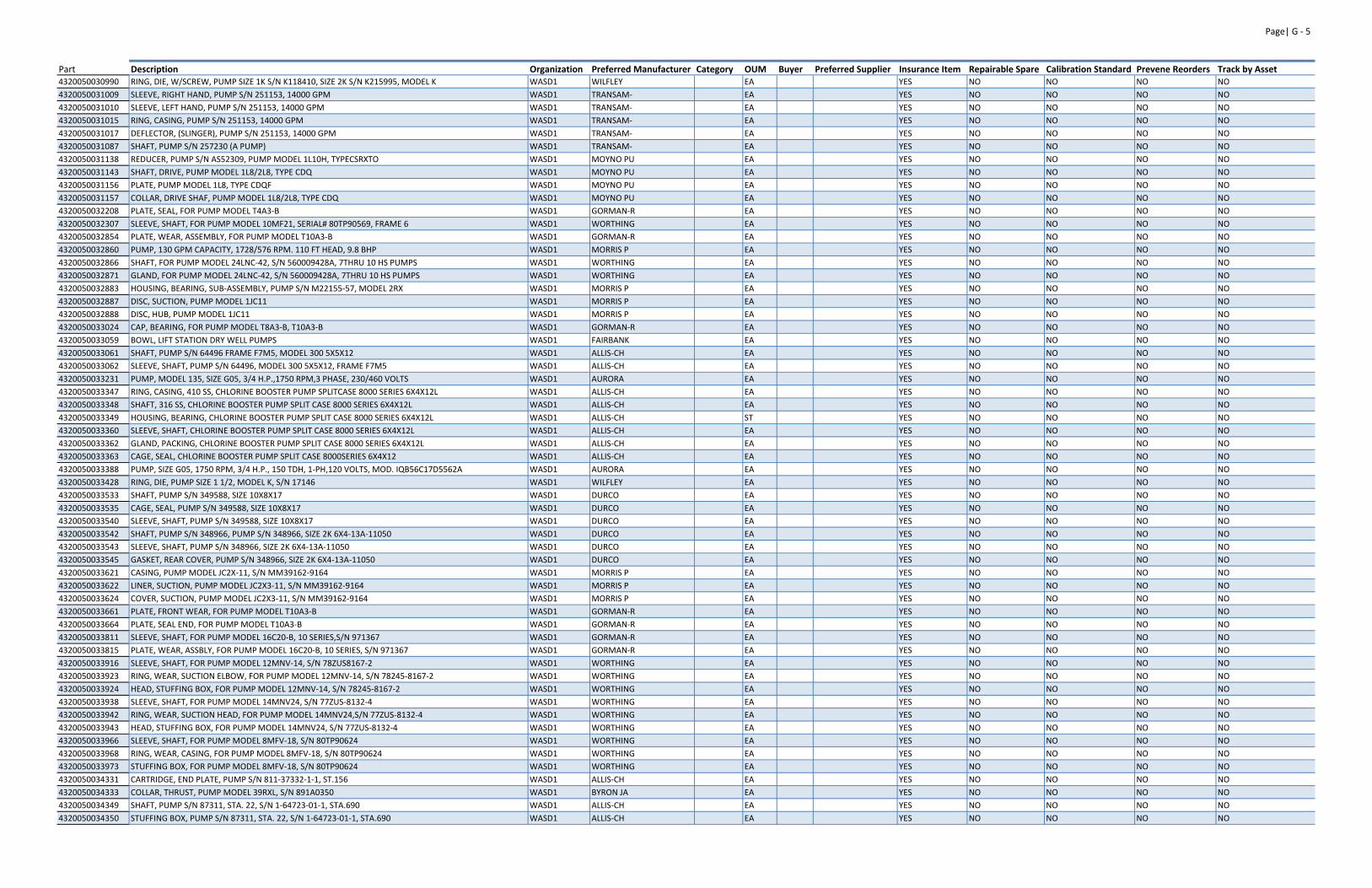
Page| G ‐ 5
Part Description Organization Preferred Manufacturer Category OUM Buyer Preferred Supplier Insurance Item Repairable Spare Calibration Standard Prevene Reorders Track by Asset4320050030990 RING, DIE, W/SCREW, PUMP SIZE 1K S/N K118410, SIZE 2K S/N K215995, MODEL K WASD1 WILFLEY EA YES NO NO NO NO
4320050031009 SLEEVE, RIGHT HAND, PUMP S/N 251153, 14000 GPM WASD1 TRANSAM‐ EA YES NO NO NO NO
4320050031010 SLEEVE, LEFT HAND, PUMP S/N 251153, 14000 GPM WASD1 TRANSAM‐ EA YES NO NO NO NO
4320050031015 RING, CASING, PUMP S/N 251153, 14000 GPM WASD1 TRANSAM‐ EA YES NO NO NO NO
4320050031017 DEFLECTOR, (SLINGER), PUMP S/N 251153, 14000 GPM WASD1 TRANSAM‐ EA YES NO NO NO NO
4320050031087 SHAFT, PUMP S/N 257230 (A PUMP) WASD1 TRANSAM‐ EA YES NO NO NO NO
4320050031138 REDUCER, PUMP S/N AS52309, PUMP MODEL 1L10H, TYPECSRXTO WASD1 MOYNO PU EA YES NO NO NO NO
4320050031143 SHAFT, DRIVE, PUMP MODEL 1L8/2L8, TYPE CDQ WASD1 MOYNO PU EA YES NO NO NO NO
4320050031156 PLATE, PUMP MODEL 1L8, TYPE CDQF WASD1 MOYNO PU EA YES NO NO NO NO
4320050031157 COLLAR, DRIVE SHAF, PUMP MODEL 1L8/2L8, TYPE CDQ WASD1 MOYNO PU EA YES NO NO NO NO
4320050032208 PLATE, SEAL, FOR PUMP MODEL T4A3‐B WASD1 GORMAN‐R EA YES NO NO NO NO
4320050032307 SLEEVE, SHAFT, FOR PUMP MODEL 10MF21, SERIAL# 80TP90569, FRAME 6 WASD1 WORTHING EA YES NO NO NO NO
4320050032854 PLATE, WEAR, ASSEMBLY, FOR PUMP MODEL T10A3‐B WASD1 GORMAN‐R EA YES NO NO NO NO
4320050032860 PUMP, 130 GPM CAPACITY, 1728/576 RPM. 110 FT HEAD, 9.8 BHP WASD1 MORRIS P EA YES NO NO NO NO
4320050032866 SHAFT, FOR PUMP MODEL 24LNC‐42, S/N 560009428A, 7THRU 10 HS PUMPS WASD1 WORTHING EA YES NO NO NO NO
4320050032871 GLAND, FOR PUMP MODEL 24LNC‐42, S/N 560009428A, 7THRU 10 HS PUMPS WASD1 WORTHING EA YES NO NO NO NO
4320050032883 HOUSING, BEARING, SUB‐ASSEMBLY, PUMP S/N M22155‐57, MODEL 2RX WASD1 MORRIS P EA YES NO NO NO NO
4320050032887 DISC, SUCTION, PUMP MODEL 1JC11 WASD1 MORRIS P EA YES NO NO NO NO
4320050032888 DISC, HUB, PUMP MODEL 1JC11 WASD1 MORRIS P EA YES NO NO NO NO
4320050033024 CAP, BEARING, FOR PUMP MODEL T8A3‐B, T10A3‐B WASD1 GORMAN‐R EA YES NO NO NO NO
4320050033059 BOWL, LIFT STATION DRY WELL PUMPS WASD1 FAIRBANK EA YES NO NO NO NO
4320050033061 SHAFT, PUMP S/N 64496 FRAME F7M5, MODEL 300 5X5X12 WASD1 ALLIS‐CH EA YES NO NO NO NO
4320050033062 SLEEVE, SHAFT, PUMP S/N 64496, MODEL 300 5X5X12, FRAME F7M5 WASD1 ALLIS‐CH EA YES NO NO NO NO
4320050033231 PUMP, MODEL 135, SIZE G05, 3/4 H.P.,1750 RPM,3 PHASE, 230/460 VOLTS WASD1 AURORA EA YES NO NO NO NO
4320050033347 RING, CASING, 410 SS, CHLORINE BOOSTER PUMP SPLITCASE 8000 SERIES 6X4X12L WASD1 ALLIS‐CH EA YES NO NO NO NO
4320050033348 SHAFT, 316 SS, CHLORINE BOOSTER PUMP SPLIT CASE 8000 SERIES 6X4X12L WASD1 ALLIS‐CH EA YES NO NO NO NO
4320050033349 HOUSING, BEARING, CHLORINE BOOSTER PUMP SPLIT CASE 8000 SERIES 6X4X12L WASD1 ALLIS‐CH ST YES NO NO NO NO
4320050033360 SLEEVE, SHAFT, CHLORINE BOOSTER PUMP SPLIT CASE 8000 SERIES 6X4X12L WASD1 ALLIS‐CH EA YES NO NO NO NO
4320050033362 GLAND, PACKING, CHLORINE BOOSTER PUMP SPLIT CASE 8000 SERIES 6X4X12L WASD1 ALLIS‐CH EA YES NO NO NO NO
4320050033363 CAGE, SEAL, CHLORINE BOOSTER PUMP SPLIT CASE 8000SERIES 6X4X12 WASD1 ALLIS‐CH EA YES NO NO NO NO
4320050033388 PUMP, SIZE G05, 1750 RPM, 3/4 H.P., 150 TDH, 1‐PH,120 VOLTS, MOD. IQB56C17D5562A WASD1 AURORA EA YES NO NO NO NO
4320050033428 RING, DIE, PUMP SIZE 1 1/2, MODEL K, S/N 17146 WASD1 WILFLEY EA YES NO NO NO NO
4320050033533 SHAFT, PUMP S/N 349588, SIZE 10X8X17 WASD1 DURCO EA YES NO NO NO NO
4320050033535 CAGE, SEAL, PUMP S/N 349588, SIZE 10X8X17 WASD1 DURCO EA YES NO NO NO NO
4320050033540 SLEEVE, SHAFT, PUMP S/N 349588, SIZE 10X8X17 WASD1 DURCO EA YES NO NO NO NO
4320050033542 SHAFT, PUMP S/N 348966, PUMP S/N 348966, SIZE 2K 6X4‐13A‐11050 WASD1 DURCO EA YES NO NO NO NO
4320050033543 SLEEVE, SHAFT, PUMP S/N 348966, SIZE 2K 6X4‐13A‐11050 WASD1 DURCO EA YES NO NO NO NO
4320050033545 GASKET, REAR COVER, PUMP S/N 348966, SIZE 2K 6X4‐13A‐11050 WASD1 DURCO EA YES NO NO NO NO
4320050033621 CASING, PUMP MODEL JC2X‐11, S/N MM39162‐9164 WASD1 MORRIS P EA YES NO NO NO NO
4320050033622 LINER, SUCTION, PUMP MODEL JC2X3‐11, S/N MM39162‐9164 WASD1 MORRIS P EA YES NO NO NO NO
4320050033624 COVER, SUCTION, PUMP MODEL JC2X3‐11, S/N MM39162‐9164 WASD1 MORRIS P EA YES NO NO NO NO
4320050033661 PLATE, FRONT WEAR, FOR PUMP MODEL T10A3‐B WASD1 GORMAN‐R EA YES NO NO NO NO
4320050033664 PLATE, SEAL END, FOR PUMP MODEL T10A3‐B WASD1 GORMAN‐R EA YES NO NO NO NO
4320050033811 SLEEVE, SHAFT, FOR PUMP MODEL 16C20‐B, 10 SERIES,S/N 971367 WASD1 GORMAN‐R EA YES NO NO NO NO
4320050033815 PLATE, WEAR, ASSBLY, FOR PUMP MODEL 16C20‐B, 10 SERIES, S/N 971367 WASD1 GORMAN‐R EA YES NO NO NO NO
4320050033916 SLEEVE, SHAFT, FOR PUMP MODEL 12MNV‐14, S/N 78ZUS8167‐2 WASD1 WORTHING EA YES NO NO NO NO
4320050033923 RING, WEAR, SUCTION ELBOW, FOR PUMP MODEL 12MNV‐14, S/N 78245‐8167‐2 WASD1 WORTHING EA YES NO NO NO NO
4320050033924 HEAD, STUFFING BOX, FOR PUMP MODEL 12MNV‐14, S/N 78245‐8167‐2 WASD1 WORTHING EA YES NO NO NO NO
4320050033938 SLEEVE, SHAFT, FOR PUMP MODEL 14MNV24, S/N 77ZUS‐8132‐4 WASD1 WORTHING EA YES NO NO NO NO
4320050033942 RING, WEAR, SUCTION HEAD, FOR PUMP MODEL 14MNV24,S/N 77ZUS‐8132‐4 WASD1 WORTHING EA YES NO NO NO NO
4320050033943 HEAD, STUFFING BOX, FOR PUMP MODEL 14MNV24, S/N 77ZUS‐8132‐4 WASD1 WORTHING EA YES NO NO NO NO
4320050033966 SLEEVE, SHAFT, FOR PUMP MODEL 8MFV‐18, S/N 80TP90624 WASD1 WORTHING EA YES NO NO NO NO
4320050033968 RING, WEAR, CASING, FOR PUMP MODEL 8MFV‐18, S/N 80TP90624 WASD1 WORTHING EA YES NO NO NO NO
4320050033973 STUFFING BOX, FOR PUMP MODEL 8MFV‐18, S/N 80TP90624 WASD1 WORTHING EA YES NO NO NO NO
4320050034331 CARTRIDGE, END PLATE, PUMP S/N 811‐37332‐1‐1, ST.156 WASD1 ALLIS‐CH EA YES NO NO NO NO
4320050034333 COLLAR, THRUST, PUMP MODEL 39RXL, S/N 891A0350 WASD1 BYRON JA EA YES NO NO NO NO
4320050034349 SHAFT, PUMP S/N 87311, STA. 22, S/N 1‐64723‐01‐1, STA.690 WASD1 ALLIS‐CH EA YES NO NO NO NO
4320050034350 STUFFING BOX, PUMP S/N 87311, STA. 22, S/N 1‐64723‐01‐1, STA.690 WASD1 ALLIS‐CH EA YES NO NO NO NO
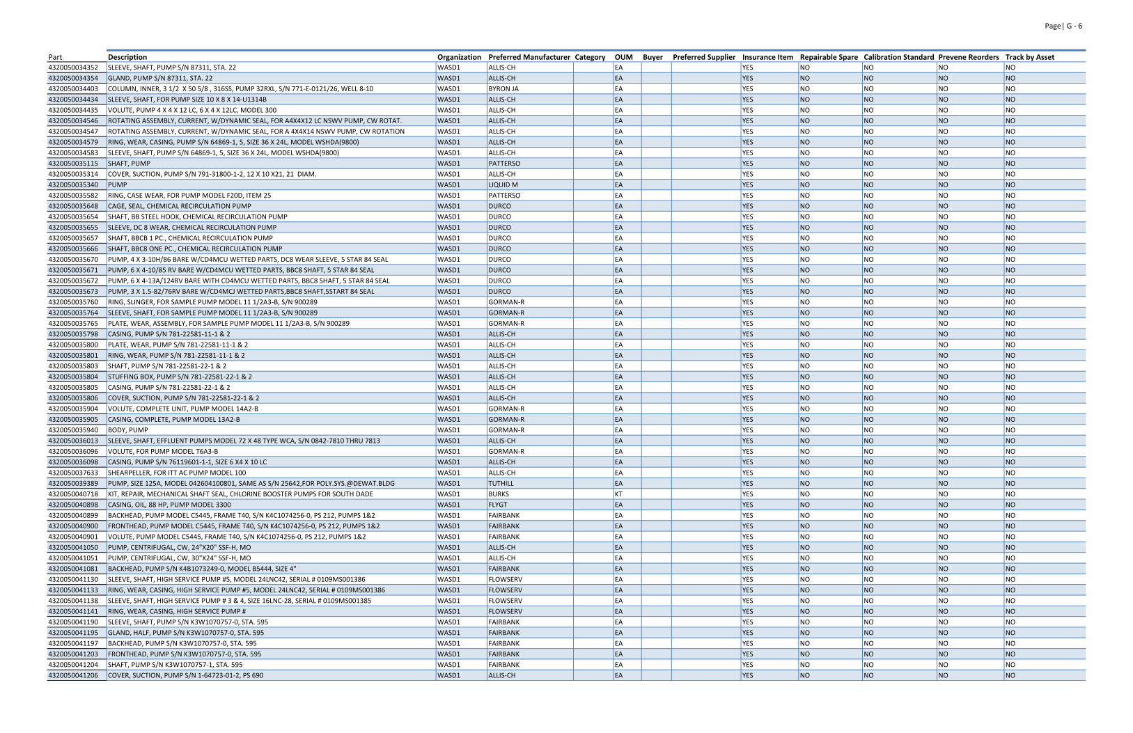
Page| G ‐ 6
Part Description Organization Preferred Manufacturer Category OUM Buyer Preferred Supplier Insurance Item Repairable Spare Calibration Standard Prevene Reorders Track by Asset4320050034352 SLEEVE, SHAFT, PUMP S/N 87311, STA. 22 WASD1 ALLIS‐CH EA YES NO NO NO NO
4320050034354 GLAND, PUMP S/N 87311, STA. 22 WASD1 ALLIS‐CH EA YES NO NO NO NO
4320050034403 COLUMN, INNER, 3 1/2 X 50 5/8 , 316SS, PUMP 32RXL, S/N 771‐E‐0121/26, WELL 8‐10 WASD1 BYRON JA EA YES NO NO NO NO
4320050034434 SLEEVE, SHAFT, FOR PUMP SIZE 10 X 8 X 14‐U1314B WASD1 ALLIS‐CH EA YES NO NO NO NO
4320050034435 VOLUTE, PUMP 4 X 4 X 12 LC, 6 X 4 X 12LC, MODEL 300 WASD1 ALLIS‐CH EA YES NO NO NO NO
4320050034546 ROTATING ASSEMBLY, CURRENT, W/DYNAMIC SEAL, FOR A4X4X12 LC NSWV PUMP, CW ROTAT. WASD1 ALLIS‐CH EA YES NO NO NO NO
4320050034547 ROTATING ASSEMBLY, CURRENT, W/DYNAMIC SEAL, FOR A 4X4X14 NSWV PUMP, CW ROTATION WASD1 ALLIS‐CH EA YES NO NO NO NO
4320050034579 RING, WEAR, CASING, PUMP S/N 64869‐1, 5, SIZE 36 X 24L, MODEL WSHDA(9800) WASD1 ALLIS‐CH EA YES NO NO NO NO
4320050034583 SLEEVE, SHAFT, PUMP S/N 64869‐1, 5, SIZE 36 X 24L, MODEL WSHDA(9800) WASD1 ALLIS‐CH EA YES NO NO NO NO
4320050035115 SHAFT, PUMP WASD1 PATTERSO EA YES NO NO NO NO
4320050035314 COVER, SUCTION, PUMP S/N 791‐31800‐1‐2, 12 X 10 X21, 21 DIAM. WASD1 ALLIS‐CH EA YES NO NO NO NO
4320050035340 PUMP WASD1 LIQUID M EA YES NO NO NO NO
4320050035582 RING, CASE WEAR, FOR PUMP MODEL F20D, ITEM 25 WASD1 PATTERSO EA YES NO NO NO NO
4320050035648 CAGE, SEAL, CHEMICAL RECIRCULATION PUMP WASD1 DURCO EA YES NO NO NO NO
4320050035654 SHAFT, BB STEEL HOOK, CHEMICAL RECIRCULATION PUMP WASD1 DURCO EA YES NO NO NO NO
4320050035655 SLEEVE, DC 8 WEAR, CHEMICAL RECIRCULATION PUMP WASD1 DURCO EA YES NO NO NO NO
4320050035657 SHAFT, BBCB 1 PC., CHEMICAL RECIRCULATION PUMP WASD1 DURCO EA YES NO NO NO NO
4320050035666 SHAFT, BBC8 ONE PC., CHEMICAL RECIRCULATION PUMP WASD1 DURCO EA YES NO NO NO NO
4320050035670 PUMP, 4 X 3‐10H/86 BARE W/CD4MCU WETTED PARTS, DC8 WEAR SLEEVE, 5 STAR 84 SEAL WASD1 DURCO EA YES NO NO NO NO
4320050035671 PUMP, 6 X 4‐10/85 RV BARE W/CD4MCU WETTED PARTS, BBC8 SHAFT, 5 STAR 84 SEAL WASD1 DURCO EA YES NO NO NO NO
4320050035672 PUMP, 6 X 4‐13A/124RV BARE WITH CD4MCU WETTED PARTS, BBC8 SHAFT, 5 STAR 84 SEAL WASD1 DURCO EA YES NO NO NO NO
4320050035673 PUMP, 3 X 1.5‐82/76RV BARE W/CD4MCJ WETTED PARTS,BBC8 SHAFT,5START 84 SEAL WASD1 DURCO EA YES NO NO NO NO
4320050035760 RING, SLINGER, FOR SAMPLE PUMP MODEL 11 1/2A3‐B, S/N 900289 WASD1 GORMAN‐R EA YES NO NO NO NO
4320050035764 SLEEVE, SHAFT, FOR SAMPLE PUMP MODEL 11 1/2A3‐B, S/N 900289 WASD1 GORMAN‐R EA YES NO NO NO NO
4320050035765 PLATE, WEAR, ASSEMBLY, FOR SAMPLE PUMP MODEL 11 1/2A3‐B, S/N 900289 WASD1 GORMAN‐R EA YES NO NO NO NO
4320050035798 CASING, PUMP S/N 781‐22581‐11‐1 & 2 WASD1 ALLIS‐CH EA YES NO NO NO NO
4320050035800 PLATE, WEAR, PUMP S/N 781‐22581‐11‐1 & 2 WASD1 ALLIS‐CH EA YES NO NO NO NO
4320050035801 RING, WEAR, PUMP S/N 781‐22581‐11‐1 & 2 WASD1 ALLIS‐CH EA YES NO NO NO NO
4320050035803 SHAFT, PUMP S/N 781‐22581‐22‐1 & 2 WASD1 ALLIS‐CH EA YES NO NO NO NO
4320050035804 STUFFING BOX, PUMP S/N 781‐22581‐22‐1 & 2 WASD1 ALLIS‐CH EA YES NO NO NO NO
4320050035805 CASING, PUMP S/N 781‐22581‐22‐1 & 2 WASD1 ALLIS‐CH EA YES NO NO NO NO
4320050035806 COVER, SUCTION, PUMP S/N 781‐22581‐22‐1 & 2 WASD1 ALLIS‐CH EA YES NO NO NO NO
4320050035904 VOLUTE, COMPLETE UNIT, PUMP MODEL 14A2‐B WASD1 GORMAN‐R EA YES NO NO NO NO
4320050035905 CASING, COMPLETE, PUMP MODEL 13A2‐B WASD1 GORMAN‐R EA YES NO NO NO NO
4320050035940 BODY, PUMP WASD1 GORMAN‐R EA YES NO NO NO NO
4320050036013 SLEEVE, SHAFT, EFFLUENT PUMPS MODEL 72 X 48 TYPE WCA, S/N 0842‐7810 THRU 7813 WASD1 ALLIS‐CH EA YES NO NO NO NO
4320050036096 VOLUTE, FOR PUMP MODEL T6A3‐B WASD1 GORMAN‐R EA YES NO NO NO NO
4320050036098 CASING, PUMP S/N 76119601‐1‐1, SIZE 6 X4 X 10 LC WASD1 ALLIS‐CH EA YES NO NO NO NO
4320050037633 SHEARPELLER, FOR ITT AC PUMP MODEL 100 WASD1 ALLIS‐CH EA YES NO NO NO NO
4320050039389 PUMP, SIZE 125A, MODEL 042604100801, SAME AS S/N 25642,FOR [email protected] WASD1 TUTHILL EA YES NO NO NO NO
4320050040718 KIT, REPAIR, MECHANICAL SHAFT SEAL, CHLORINE BOOSTER PUMPS FOR SOUTH DADE WASD1 BURKS KT YES NO NO NO NO
4320050040898 CASING, OIL, 88 HP, PUMP MODEL 3300 WASD1 FLYGT EA YES NO NO NO NO
4320050040899 BACKHEAD, PUMP MODEL C5445, FRAME T40, S/N K4C1074256‐0, PS 212, PUMPS 1&2 WASD1 FAIRBANK EA YES NO NO NO NO
4320050040900 FRONTHEAD, PUMP MODEL C5445, FRAME T40, S/N K4C1074256‐0, PS 212, PUMPS 1&2 WASD1 FAIRBANK EA YES NO NO NO NO
4320050040901 VOLUTE, PUMP MODEL C5445, FRAME T40, S/N K4C1074256‐0, PS 212, PUMPS 1&2 WASD1 FAIRBANK EA YES NO NO NO NO
4320050041050 PUMP, CENTRIFUGAL, CW, 24"X20" SSF‐H, MO WASD1 ALLIS‐CH EA YES NO NO NO NO
4320050041051 PUMP, CENTRIFUGAL, CW, 30"X24" SSF‐H, MO WASD1 ALLIS‐CH EA YES NO NO NO NO
4320050041081 BACKHEAD, PUMP S/N K4B1073249‐0, MODEL B5444, SIZE 4" WASD1 FAIRBANK EA YES NO NO NO NO
4320050041130 SLEEVE, SHAFT, HIGH SERVICE PUMP #5, MODEL 24LNC42, SERIAL # 0109MS001386 WASD1 FLOWSERV EA YES NO NO NO NO
4320050041133 RING, WEAR, CASING, HIGH SERVICE PUMP #5, MODEL 24LNC42, SERIAL # 0109MS001386 WASD1 FLOWSERV EA YES NO NO NO NO
4320050041138 SLEEVE, SHAFT, HIGH SERVICE PUMP # 3 & 4, SIZE 16LNC‐28, SERIAL # 0109MS001385 WASD1 FLOWSERV EA YES NO NO NO NO
4320050041141 RING, WEAR, CASING, HIGH SERVICE PUMP # WASD1 FLOWSERV EA YES NO NO NO NO
4320050041190 SLEEVE, SHAFT, PUMP S/N K3W1070757‐0, STA. 595 WASD1 FAIRBANK EA YES NO NO NO NO
4320050041195 GLAND, HALF, PUMP S/N K3W1070757‐0, STA. 595 WASD1 FAIRBANK EA YES NO NO NO NO
4320050041197 BACKHEAD, PUMP S/N K3W1070757‐0, STA. 595 WASD1 FAIRBANK EA YES NO NO NO NO
4320050041203 FRONTHEAD, PUMP S/N K3W1070757‐0, STA. 595 WASD1 FAIRBANK EA YES NO NO NO NO
4320050041204 SHAFT, PUMP S/N K3W1070757‐1, STA. 595 WASD1 FAIRBANK EA YES NO NO NO NO
4320050041206 COVER, SUCTION, PUMP S/N 1‐64723‐01‐2, PS 690 WASD1 ALLIS‐CH EA YES NO NO NO NO
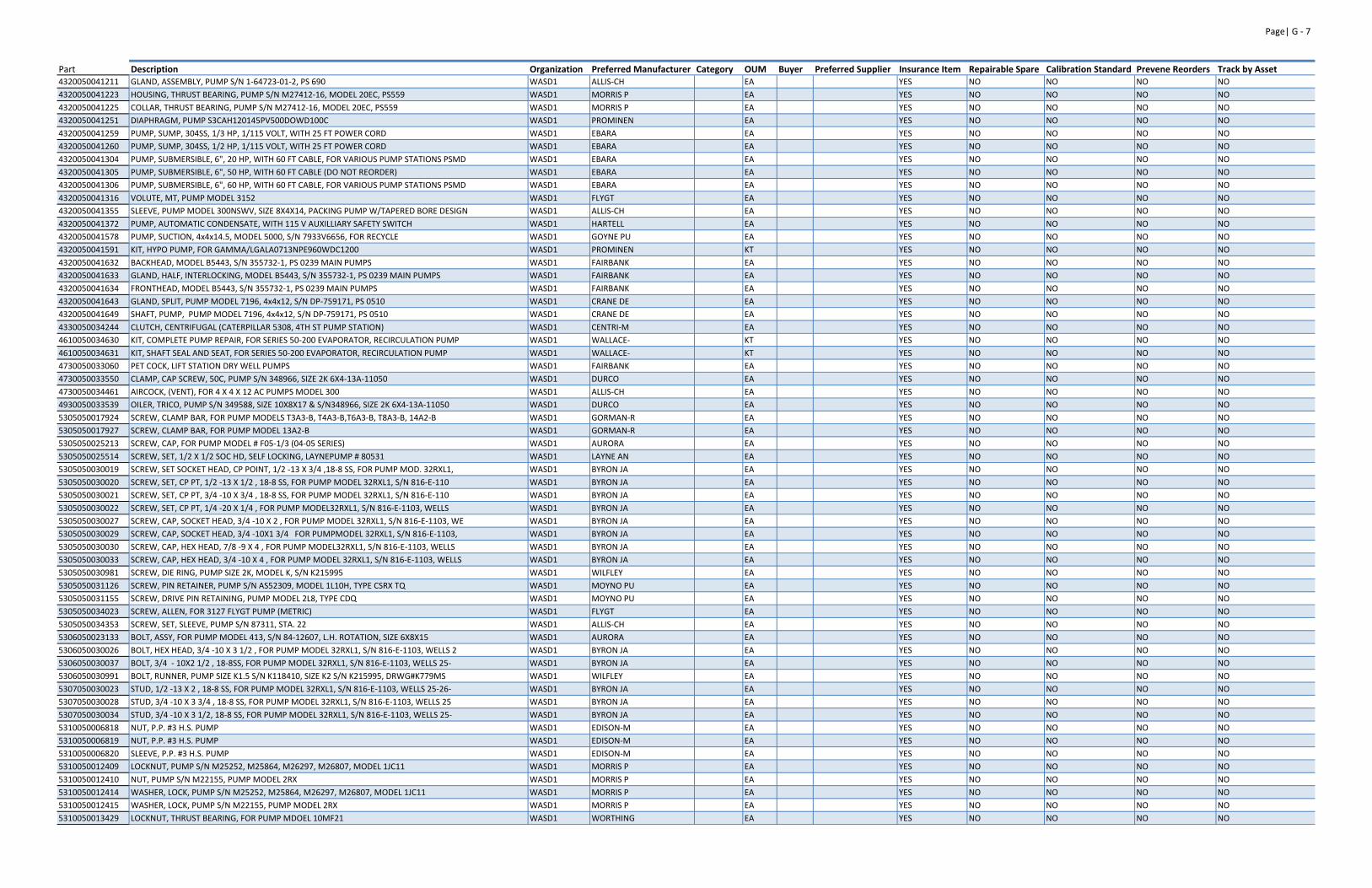
Page| G ‐ 7
Part Description Organization Preferred Manufacturer Category OUM Buyer Preferred Supplier Insurance Item Repairable Spare Calibration Standard Prevene Reorders Track by Asset4320050041211 GLAND, ASSEMBLY, PUMP S/N 1‐64723‐01‐2, PS 690 WASD1 ALLIS‐CH EA YES NO NO NO NO
4320050041223 HOUSING, THRUST BEARING, PUMP S/N M27412‐16, MODEL 20EC, PS559 WASD1 MORRIS P EA YES NO NO NO NO
4320050041225 COLLAR, THRUST BEARING, PUMP S/N M27412‐16, MODEL 20EC, PS559 WASD1 MORRIS P EA YES NO NO NO NO
4320050041251 DIAPHRAGM, PUMP S3CAH120145PV500DOWD100C WASD1 PROMINEN EA YES NO NO NO NO
4320050041259 PUMP, SUMP, 304SS, 1/3 HP, 1/115 VOLT, WITH 25 FT POWER CORD WASD1 EBARA EA YES NO NO NO NO
4320050041260 PUMP, SUMP, 304SS, 1/2 HP, 1/115 VOLT, WITH 25 FT POWER CORD WASD1 EBARA EA YES NO NO NO NO
4320050041304 PUMP, SUBMERSIBLE, 6", 20 HP, WITH 60 FT CABLE, FOR VARIOUS PUMP STATIONS PSMD WASD1 EBARA EA YES NO NO NO NO
4320050041305 PUMP, SUBMERSIBLE, 6", 50 HP, WITH 60 FT CABLE (DO NOT REORDER) WASD1 EBARA EA YES NO NO NO NO
4320050041306 PUMP, SUBMERSIBLE, 6", 60 HP, WITH 60 FT CABLE, FOR VARIOUS PUMP STATIONS PSMD WASD1 EBARA EA YES NO NO NO NO
4320050041316 VOLUTE, MT, PUMP MODEL 3152 WASD1 FLYGT EA YES NO NO NO NO
4320050041355 SLEEVE, PUMP MODEL 300NSWV, SIZE 8X4X14, PACKING PUMP W/TAPERED BORE DESIGN WASD1 ALLIS‐CH EA YES NO NO NO NO
4320050041372 PUMP, AUTOMATIC CONDENSATE, WITH 115 V AUXILLIARY SAFETY SWITCH WASD1 HARTELL EA YES NO NO NO NO
4320050041578 PUMP, SUCTION, 4x4x14.5, MODEL 5000, S/N 7933V6656, FOR RECYCLE WASD1 GOYNE PU EA YES NO NO NO NO
4320050041591 KIT, HYPO PUMP, FOR GAMMA/LGALA0713NPE960WDC1200 WASD1 PROMINEN KT YES NO NO NO NO
4320050041632 BACKHEAD, MODEL B5443, S/N 355732‐1, PS 0239 MAIN PUMPS WASD1 FAIRBANK EA YES NO NO NO NO
4320050041633 GLAND, HALF, INTERLOCKING, MODEL B5443, S/N 355732‐1, PS 0239 MAIN PUMPS WASD1 FAIRBANK EA YES NO NO NO NO
4320050041634 FRONTHEAD, MODEL B5443, S/N 355732‐1, PS 0239 MAIN PUMPS WASD1 FAIRBANK EA YES NO NO NO NO
4320050041643 GLAND, SPLIT, PUMP MODEL 7196, 4x4x12, S/N DP‐759171, PS 0510 WASD1 CRANE DE EA YES NO NO NO NO
4320050041649 SHAFT, PUMP, PUMP MODEL 7196, 4x4x12, S/N DP‐759171, PS 0510 WASD1 CRANE DE EA YES NO NO NO NO
4330050034244 CLUTCH, CENTRIFUGAL (CATERPILLAR 5308, 4TH ST PUMP STATION) WASD1 CENTRI‐M EA YES NO NO NO NO
4610050034630 KIT, COMPLETE PUMP REPAIR, FOR SERIES 50‐200 EVAPORATOR, RECIRCULATION PUMP WASD1 WALLACE‐ KT YES NO NO NO NO
4610050034631 KIT, SHAFT SEAL AND SEAT, FOR SERIES 50‐200 EVAPORATOR, RECIRCULATION PUMP WASD1 WALLACE‐ KT YES NO NO NO NO
4730050033060 PET COCK, LIFT STATION DRY WELL PUMPS WASD1 FAIRBANK EA YES NO NO NO NO
4730050033550 CLAMP, CAP SCREW, 50C, PUMP S/N 348966, SIZE 2K 6X4‐13A‐11050 WASD1 DURCO EA YES NO NO NO NO
4730050034461 AIRCOCK, (VENT), FOR 4 X 4 X 12 AC PUMPS MODEL 300 WASD1 ALLIS‐CH EA YES NO NO NO NO
4930050033539 OILER, TRICO, PUMP S/N 349588, SIZE 10X8X17 & S/N348966, SIZE 2K 6X4‐13A‐11050 WASD1 DURCO EA YES NO NO NO NO
5305050017924 SCREW, CLAMP BAR, FOR PUMP MODELS T3A3‐B, T4A3‐B,T6A3‐B, T8A3‐B, 14A2‐B WASD1 GORMAN‐R EA YES NO NO NO NO
5305050017927 SCREW, CLAMP BAR, FOR PUMP MODEL 13A2‐B WASD1 GORMAN‐R EA YES NO NO NO NO
5305050025213 SCREW, CAP, FOR PUMP MODEL # F05‐1/3 (04‐05 SERIES) WASD1 AURORA EA YES NO NO NO NO
5305050025514 SCREW, SET, 1/2 X 1/2 SOC HD, SELF LOCKING, LAYNEPUMP # 80531 WASD1 LAYNE AN EA YES NO NO NO NO
5305050030019 SCREW, SET SOCKET HEAD, CP POINT, 1/2 ‐13 X 3/4 ,18‐8 SS, FOR PUMP MOD. 32RXL1, WASD1 BYRON JA EA YES NO NO NO NO
5305050030020 SCREW, SET, CP PT, 1/2 ‐13 X 1/2 , 18‐8 SS, FOR PUMP MODEL 32RXL1, S/N 816‐E‐110 WASD1 BYRON JA EA YES NO NO NO NO
5305050030021 SCREW, SET, CP PT, 3/4 ‐10 X 3/4 , 18‐8 SS, FOR PUMP MODEL 32RXL1, S/N 816‐E‐110 WASD1 BYRON JA EA YES NO NO NO NO
5305050030022 SCREW, SET, CP PT, 1/4 ‐20 X 1/4 , FOR PUMP MODEL32RXL1, S/N 816‐E‐1103, WELLS WASD1 BYRON JA EA YES NO NO NO NO
5305050030027 SCREW, CAP, SOCKET HEAD, 3/4 ‐10 X 2 , FOR PUMP MODEL 32RXL1, S/N 816‐E‐1103, WE WASD1 BYRON JA EA YES NO NO NO NO
5305050030029 SCREW, CAP, SOCKET HEAD, 3/4 ‐10X1 3/4 FOR PUMPMODEL 32RXL1, S/N 816‐E‐1103, WASD1 BYRON JA EA YES NO NO NO NO
5305050030030 SCREW, CAP, HEX HEAD, 7/8 ‐9 X 4 , FOR PUMP MODEL32RXL1, S/N 816‐E‐1103, WELLS WASD1 BYRON JA EA YES NO NO NO NO
5305050030033 SCREW, CAP, HEX HEAD, 3/4 ‐10 X 4 , FOR PUMP MODEL 32RXL1, S/N 816‐E‐1103, WELLS WASD1 BYRON JA EA YES NO NO NO NO
5305050030981 SCREW, DIE RING, PUMP SIZE 2K, MODEL K, S/N K215995 WASD1 WILFLEY EA YES NO NO NO NO
5305050031126 SCREW, PIN RETAINER, PUMP S/N AS52309, MODEL 1L10H, TYPE CSRX TQ WASD1 MOYNO PU EA YES NO NO NO NO
5305050031155 SCREW, DRIVE PIN RETAINING, PUMP MODEL 2L8, TYPE CDQ WASD1 MOYNO PU EA YES NO NO NO NO
5305050034023 SCREW, ALLEN, FOR 3127 FLYGT PUMP (METRIC) WASD1 FLYGT EA YES NO NO NO NO
5305050034353 SCREW, SET, SLEEVE, PUMP S/N 87311, STA. 22 WASD1 ALLIS‐CH EA YES NO NO NO NO
5306050023133 BOLT, ASSY, FOR PUMP MODEL 413, S/N 84‐12607, L.H. ROTATION, SIZE 6X8X15 WASD1 AURORA EA YES NO NO NO NO
5306050030026 BOLT, HEX HEAD, 3/4 ‐10 X 3 1/2 , FOR PUMP MODEL 32RXL1, S/N 816‐E‐1103, WELLS 2 WASD1 BYRON JA EA YES NO NO NO NO
5306050030037 BOLT, 3/4 ‐ 10X2 1/2 , 18‐8SS, FOR PUMP MODEL 32RXL1, S/N 816‐E‐1103, WELLS 25‐ WASD1 BYRON JA EA YES NO NO NO NO
5306050030991 BOLT, RUNNER, PUMP SIZE K1.5 S/N K118410, SIZE K2 S/N K215995, DRWG#K779MS WASD1 WILFLEY EA YES NO NO NO NO
5307050030023 STUD, 1/2 ‐13 X 2 , 18‐8 SS, FOR PUMP MODEL 32RXL1, S/N 816‐E‐1103, WELLS 25‐26‐ WASD1 BYRON JA EA YES NO NO NO NO
5307050030028 STUD, 3/4 ‐10 X 3 3/4 , 18‐8 SS, FOR PUMP MODEL 32RXL1, S/N 816‐E‐1103, WELLS 25 WASD1 BYRON JA EA YES NO NO NO NO
5307050030034 STUD, 3/4 ‐10 X 3 1/2, 18‐8 SS, FOR PUMP MODEL 32RXL1, S/N 816‐E‐1103, WELLS 25‐ WASD1 BYRON JA EA YES NO NO NO NO
5310050006818 NUT, P.P. #3 H.S. PUMP WASD1 EDISON‐M EA YES NO NO NO NO
5310050006819 NUT, P.P. #3 H.S. PUMP WASD1 EDISON‐M EA YES NO NO NO NO
5310050006820 SLEEVE, P.P. #3 H.S. PUMP WASD1 EDISON‐M EA YES NO NO NO NO
5310050012409 LOCKNUT, PUMP S/N M25252, M25864, M26297, M26807, MODEL 1JC11 WASD1 MORRIS P EA YES NO NO NO NO
5310050012410 NUT, PUMP S/N M22155, PUMP MODEL 2RX WASD1 MORRIS P EA YES NO NO NO NO
5310050012414 WASHER, LOCK, PUMP S/N M25252, M25864, M26297, M26807, MODEL 1JC11 WASD1 MORRIS P EA YES NO NO NO NO
5310050012415 WASHER, LOCK, PUMP S/N M22155, PUMP MODEL 2RX WASD1 MORRIS P EA YES NO NO NO NO
5310050013429 LOCKNUT, THRUST BEARING, FOR PUMP MDOEL 10MF21 WASD1 WORTHING EA YES NO NO NO NO
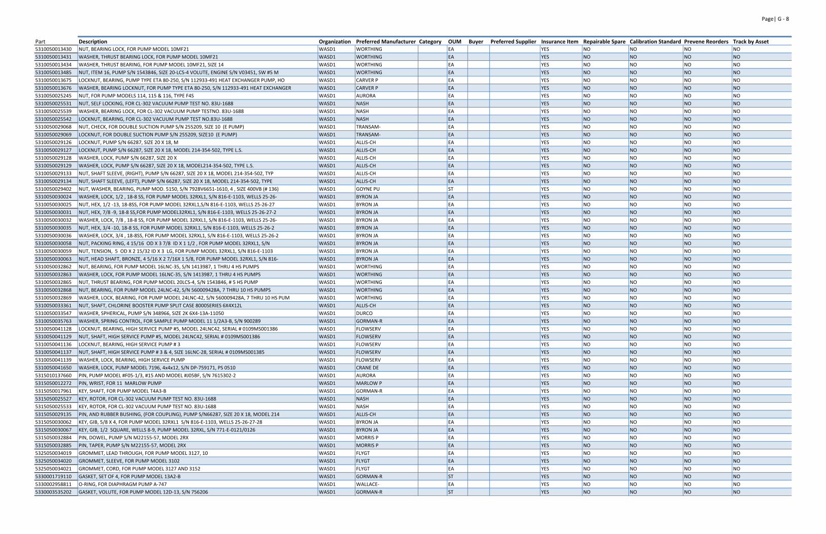
Page| G ‐ 8
Part Description Organization Preferred Manufacturer Category OUM Buyer Preferred Supplier Insurance Item Repairable Spare Calibration Standard Prevene Reorders Track by Asset5310050013430 NUT, BEARING LOCK, FOR PUMP MODEL 10MF21 WASD1 WORTHING EA YES NO NO NO NO
5310050013431 WASHER, THRUST BEARING LOCK, FOR PUMP MODEL 10MF21 WASD1 WORTHING EA YES NO NO NO NO
5310050013434 WASHER, THRUST BEARING, FOR PUMP MODEL 10MF21, SIZE 14 WASD1 WORTHING EA YES NO NO NO NO
5310050013485 NUT, ITEM 16, PUMP S/N 1543846, SIZE 20‐LCS‐4 VOLUTE, ENGINE S/N V03451, SW #5 M WASD1 WORTHING EA YES NO NO NO NO
5310050013675 LOCKNUT, BEARING, PUMP TYPE ETA 80‐250, S/N 112933‐491 HEAT EXCHANGER PUMP, HO WASD1 CARVER P EA YES NO NO NO NO
5310050013676 WASHER, BEARING LOCKNUT, FOR PUMP TYPE ETA 80‐250, S/N 112933‐491 HEAT EXCHANGER WASD1 CARVER P EA YES NO NO NO NO
5310050025245 NUT, FOR PUMP MODELS 114, 115 & 116, TYPE F4S WASD1 AURORA EA YES NO NO NO NO
5310050025531 NUT, SELF LOCKING, FOR CL‐302 VACUUM PUMP TEST NO. 83U‐1688 WASD1 NASH EA YES NO NO NO NO
5310050025539 WASHER, BEARING LOCK, FOR CL‐302 VACUUM PUMP TESTNO. 83U‐1688 WASD1 NASH EA YES NO NO NO NO
5310050025542 LOCKNUT, BEARING, FOR CL‐302 VACUUM PUMP TEST NO.83U‐1688 WASD1 NASH EA YES NO NO NO NO
5310050029068 NUT, CHECK, FOR DOUBLE SUCTION PUMP S/N 255209, SIZE 10 (E PUMP) WASD1 TRANSAM‐ EA YES NO NO NO NO
5310050029069 LOCKNUT, FOR DOUBLE SUCTION PUMP S/N 255209, SIZE10 (E PUMP) WASD1 TRANSAM‐ EA YES NO NO NO NO
5310050029126 LOCKNUT, PUMP S/N 66287, SIZE 20 X 18, M WASD1 ALLIS‐CH EA YES NO NO NO NO
5310050029127 LOCKNUT, PUMP S/N 66287, SIZE 20 X 18, MODEL 214‐354‐502, TYPE L.S. WASD1 ALLIS‐CH EA YES NO NO NO NO
5310050029128 WASHER, LOCK, PUMP S/N 66287, SIZE 20 X WASD1 ALLIS‐CH EA YES NO NO NO NO
5310050029129 WASHER, LOCK, PUMP S/N 66287, SIZE 20 X 18, MODEL214‐354‐502, TYPE L.S. WASD1 ALLIS‐CH EA YES NO NO NO NO
5310050029133 NUT, SHAFT SLEEVE, (RIGHT), PUMP S/N 66287, SIZE 20 X 18, MODEL 214‐354‐502, TYP WASD1 ALLIS‐CH EA YES NO NO NO NO
5310050029134 NUT, SHAFT SLEEVE, (LEFT), PUMP S/N 66287, SIZE 20 X 18, MODEL 214‐354‐502, TYPE WASD1 ALLIS‐CH EA YES NO NO NO NO
5310050029402 NUT, WASHER, BEARING, PUMP MOD. 5150, S/N 7928V6651‐1610, 4 , SIZE 400VB (# 136) WASD1 GOYNE PU ST YES NO NO NO NO
5310050030024 WASHER, LOCK, 1/2 , 18‐8 SS, FOR PUMP MODEL 32RXL1, S/N 816‐E‐1103, WELLS 25‐26‐ WASD1 BYRON JA EA YES NO NO NO NO
5310050030025 NUT, HEX, 1/2 ‐13, 18‐8SS, FOR PUMP MODEL 32RXL1,S/N 816‐E‐1103, WELLS 25‐26‐27 WASD1 BYRON JA EA YES NO NO NO NO
5310050030031 NUT, HEX, 7/8 ‐9, 18‐8 SS,FOR PUMP MODEL32RXL1, S/N 816‐E‐1103, WELLS 25‐26‐27‐2 WASD1 BYRON JA EA YES NO NO NO NO
5310050030032 WASHER, LOCK, 7/8 , 18‐8 SS, FOR PUMP MODEL 32RXL1, S/N 816‐E‐1103, WELLS 25‐26‐ WASD1 BYRON JA EA YES NO NO NO NO
5310050030035 NUT, HEX, 3/4 ‐10, 18‐8 SS, FOR PUMP MODEL 32RXL1, S/N 816‐E‐1103, WELLS 25‐26‐2 WASD1 BYRON JA EA YES NO NO NO NO
5310050030036 WASHER, LOCK, 3/4 , 18‐8SS, FOR PUMP MODEL 32RXL1, S/N 816‐E‐1103, WELLS 25‐26‐2 WASD1 BYRON JA EA YES NO NO NO NO
5310050030058 NUT, PACKING RING, 4 15/16 OD X 3 7/8 ID X 1 1/2 , FOR PUMP MODEL 32RXL1, S/N WASD1 BYRON JA EA YES NO NO NO NO
5310050030059 NUT, TENSION, 5 OD X 2 15/32 ID X 3 LG, FOR PUMP MODEL 32RXL1, S/N 816‐E‐1103 WASD1 BYRON JA EA YES NO NO NO NO
5310050030063 NUT, HEAD SHAFT, BRONZE, 4 5/16 X 2 7/16X 1 5/8, FOR PUMP MODEL 32RXL1, S/N 816‐ WASD1 BYRON JA EA YES NO NO NO NO
5310050032862 NUT, BEARING, FOR PUMP MODEL 16LNC‐35, S/N 1413987, 1 THRU 4 HS PUMPS WASD1 WORTHING EA YES NO NO NO NO
5310050032863 WASHER, LOCK, FOR PUMP MODEL 16LNC‐35, S/N 1413987, 1 THRU 4 HS PUMPS WASD1 WORTHING EA YES NO NO NO NO
5310050032865 NUT, THRUST BEARING, FOR PUMP MODEL 20LCS‐4, S/N 1543846, # 5 HS PUMP WASD1 WORTHING EA YES NO NO NO NO
5310050032868 NUT, BEARING, FOR PUMP MODEL 24LNC‐42, S/N 560009428A, 7 THRU 10 HS PUMPS WASD1 WORTHING EA YES NO NO NO NO
5310050032869 WASHER, LOCK, BEARING, FOR PUMP MODEL 24LNC‐42, S/N 560009428A, 7 THRU 10 HS PUM WASD1 WORTHING EA YES NO NO NO NO
5310050033361 NUT, SHAFT, CHLORINE BOOSTER PUMP SPLIT CASE 8000SERIES 6X4X12L WASD1 ALLIS‐CH EA YES NO NO NO NO
5310050033547 WASHER, SPHERICAL, PUMP S/N 348966, SIZE 2K 6X4‐13A‐11050 WASD1 DURCO EA YES NO NO NO NO
5310050035763 WASHER, SPRING CONTROL, FOR SAMPLE PUMP MODEL 11 1/2A3‐B, S/N 900289 WASD1 GORMAN‐R EA YES NO NO NO NO
5310050041128 LOCKNUT, BEARING, HIGH SERVICE PUMP #5, MODEL 24LNC42, SERIAL # 0109MS001386 WASD1 FLOWSERV EA YES NO NO NO NO
5310050041129 NUT, SHAFT, HIGH SERVICE PUMP #5, MODEL 24LNC42, SERIAL # 0109MS001386 WASD1 FLOWSERV EA YES NO NO NO NO
5310050041136 LOCKNUT, BEARING, HIGH SERVICE PUMP # 3 WASD1 FLOWSERV EA YES NO NO NO NO
5310050041137 NUT, SHAFT, HIGH SERVICE PUMP # 3 & 4, SIZE 16LNC‐28, SERIAL # 0109MS001385 WASD1 FLOWSERV EA YES NO NO NO NO
5310050041139 WASHER, LOCK, BEARING, HIGH SERVICE PUMP WASD1 FLOWSERV EA YES NO NO NO NO
5310050041650 WASHER, LOCK, PUMP MODEL 7196, 4x4x12, S/N DP‐759171, PS 0510 WASD1 CRANE DE EA YES NO NO NO NO
5315010137660 PIN, PUMP MODEL #F05‐1/3, #15 AND MODEL #J05BF, S/N 7615302‐2 WASD1 AURORA EA YES NO NO NO NO
5315050012272 PIN, WRIST, FOR 11 MARLOW PUMP WASD1 MARLOW P EA YES NO NO NO NO
5315050017961 KEY, SHAFT, FOR PUMP MODEL T4A3‐B WASD1 GORMAN‐R EA YES NO NO NO NO
5315050025527 KEY, ROTOR, FOR CL‐302 VACUUM PUMP TEST NO. 83U‐1688 WASD1 NASH EA YES NO NO NO NO
5315050025533 KEY, ROTOR, FOR CL‐302 VACUUM PUMP TEST NO. 83U‐1688 WASD1 NASH EA YES NO NO NO NO
5315050029135 PIN, AND RUBBER BUSHING, (FOR COUPLING), PUMP S/N66287, SIZE 20 X 18, MODEL 214 WASD1 ALLIS‐CH EA YES NO NO NO NO
5315050030062 KEY, GIB, 5/8 X 4, FOR PUMP MODEL 32RXL1 S/N 816‐E‐1103, WELLS 25‐26‐27‐28 WASD1 BYRON JA EA YES NO NO NO NO
5315050030067 KEY, GIB, 1/2 SQUARE, WELLS 8‐9, PUMP MODEL 32RXL, S/N 771‐E‐0121/0126 WASD1 BYRON JA EA YES NO NO NO NO
5315050032884 PIN, DOWEL, PUMP S/N M22155‐57, MODEL 2RX WASD1 MORRIS P EA YES NO NO NO NO
5315050032885 PIN, TAPER, PUMP S/N M22155‐57, MODEL 2RX WASD1 MORRIS P EA YES NO NO NO NO
5325050034019 GROMMET, LEAD THROUGH, FOR PUMP MODEL 3127, 10 WASD1 FLYGT EA YES NO NO NO NO
5325050034020 GROMMET, SLEEVE, FOR PUMP MODEL 3102 WASD1 FLYGT EA YES NO NO NO NO
5325050034021 GROMMET, CORD, FOR PUMP MODEL 3127 AND 3152 WASD1 FLYGT EA YES NO NO NO NO
5330001719110 GASKET, SET OF 4, FOR PUMP MODEL 13A2‐B WASD1 GORMAN‐R ST YES NO NO NO NO
5330002958811 O‐RING, FOR DIAPHRAGM PUMP A‐747 WASD1 WALLACE‐ EA YES NO NO NO NO
5330003535202 GASKET, VOLUTE, FOR PUMP MODEL 12D‐13, S/N 756206 WASD1 GORMAN‐R ST YES NO NO NO NO
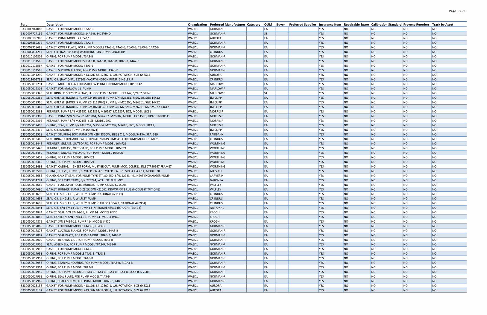
Page| G ‐ 9
Part Description Organization Preferred Manufacturer Category OUM Buyer Preferred Supplier Insurance Item Repairable Spare Calibration Standard Prevene Reorders Track by Asset5330005941082 GASKET, FOR PUMP MODEL 13A2‐B WASD1 GORMAN‐R EA YES NO NO NO NO
5330007727196 GASKET, FOR PUMP MODELS 14A2‐B, 14C2VH4D WASD1 GORMAN‐R ST YES NO NO NO NO
5330008190980 GASKET, PUMP MODEL # F05‐1/3 WASD1 AURORA EA YES NO NO NO NO
5330008889212 GASKET, FOR PUMP MODEL 14A2‐B WASD1 GORMAN‐R EA YES NO NO NO NO
5330009318688 GASKET, COVER PLATE, FOR PUMP MODELS T3A3‐B, T4A3‐B, T6A3‐B, T8A3‐B, 14A2‐B WASD1 GORMAN‐R EA YES NO NO NO NO
5330009834217 SEAL, OIL, (NAT. 457349) WORTHINGTON PUMP, SINGLELIP WASD1 CR INDUS EA YES NO NO NO NO
5330010109802 O‐RING, FOR PUMP MODEL T3A3‐B WASD1 GORMAN‐R EA YES NO NO NO NO
5330010111566 GASKET, FOR PUMP MODELS T3A3‐B, T4A3‐B, T6A3‐B, T8A3‐B, 14A2‐B WASD1 GORMAN‐R EA YES NO NO NO NO
5330010111567 GASKET, FOR PUMP MODEL T3A3‐B WASD1 GORMAN‐R EA YES NO NO NO NO
5330010111568 GASKET, SUCTION FLANGE, FOR PUMP MODEL T3A3‐B WASD1 GORMAN‐R EA YES NO NO NO NO
5330010841290 GASKET, FOR PUMP MODEL 413, S/N 84‐12607‐1, L.H. ROTATION, SIZE 6X8X15 WASD1 AURORA EA YES NO NO NO NO
5330011605732 SEAL, OIL, (NATIONAL 327303) WORTHINGTON PUMP, SINGLE LIP WASD1 CR INDUS EA YES NO NO NO NO
5330050012291 GASKET, MOLDED 456, FOR MARLOW PLUNGER PUMP MODEL HPE1142 WASD1 MARLOW P EA YES NO NO NO NO
5330050012308 GASKET, FOR MARLOW 11 PUMP WASD1 MARLOW P EA YES NO NO NO NO
5330050012348 SEAL, RING, 11"x12"x2"x2 3/4", SLUDGE PUMP MODEL HPE1142, S/N 67, SET=5 WASD1 MARLOW P ST YES NO NO NO NO
5330050012365 SEAL, GREASE, (MORRIS PUMP 9241095058) PUMP S/N M26261, M26260, SIZE 14X12 WASD1 JM CLIPP EA YES NO NO NO NO
5330050012366 SEAL, GREASE, (MORRIS PUMP 9241111070) PUMP S/N M26260, M26261, SIZE 14X12 WASD1 JM CLIPP EA YES NO NO NO NO
5330050012367 SEAL, GREASE, (MORRIS PUMP 9241070035, PUMP S/N M26260, M26261, M26259 SZ 14X12 WASD1 JM CLIPP EA YES NO NO NO NO
5330050012381 RETAINER, PUMP S/N M25252, M25864, M26297, M26807, SIZE, MODEL 1JC11 WASD1 MORRIS P EA YES NO NO NO NO
5330050012388 GASKET, PUMP S/N M25252, M25864, M26297, M26807, MODEL 1JC11SPD, 049751G0305115 WASD1 MORRIS P EA YES NO NO NO NO
5330050012392 RETAINER, PUMP S/N M22155, SIZE, MODEL 2RX WASD1 MORRIS P EA YES NO NO NO NO
5330050012408 O‐RING, SEAL, PUMP S/N M25252, M25864, M26297, M2680, SIZE, MODEL 1JC11, WASD1 MORRIS P EA YES NO NO NO NO
5330050012412 SEAL, OIL (MORRIS PUMP 9241048021) WASD1 JM CLIPP EA YES NO NO NO NO
5330050012518 GASKET, STUFFING BOX, PUMP S/N K2B4536CW, SIZE 8 X 5, MODEL 5413A, STA. 639 WASD1 FAIRBANK EA YES NO NO NO NO
5330050013446 SEAL, RING, OUTBOARD, (WORTHINGTON 8449 ITM# 49) FOR PUMP MODEL 10MF21 WASD1 CR INDUS EA YES NO NO NO NO
5330050013448 RETAINER, GREASE, OUTBOARD, FOR PUMP MODEL 10MF21 WASD1 WORTHING EA YES NO NO NO NO
5330050013449 RETAINER, GREASE, OUTBOARD, FOR PUMP MODEL 10MF21 WASD1 WORTHING EA YES NO NO NO NO
5330050013450 RETAINER, GREASE, INBOARD, FOR PUMP MODEL 10MF21 WASD1 WORTHING EA YES NO NO NO NO
5330050013459 O‐RING, FOR PUMP MODEL 10MF21 WASD1 WORTHING EA YES NO NO NO NO
5330050013460 O‐RING, FOR PUMP MODEL 10MF21 WASD1 WORTHING EA YES NO NO NO NO
5330050013491 GASKET, CASING, 4 SHEET FORM, MUST BE CUT, PUMP MOD. 10MF21,SN.80TP90567,FRAME7 WASD1 WORTHING EA YES NO NO NO NO
5330050013502 O‐RING, SLEEVE, PUMP S/N 791‐31932‐4‐1, 791‐31932‐5‐1, SIZE 4 X 4 X 14, MODEL 30 WASD1 ALLIS‐CH EA YES NO NO NO NO
5330050013685 GLAND, GASKET SEAL, FOR PUMP TYPE ETA 80‐250, S/N112933‐491 HEAT EXCHANGER PUMP WASD1 CARVER P EA YES NO NO NO NO
5330050014274 O‐RING, FOR TYPE 24KXL, S/N 279744, WELL FIELD PUMPS WASD1 BYRON JA EA YES NO NO NO NO
5330050014686 GASKET, FOLLOWER PLATE, RUBBER, PUMP K2, S/N K215995 WASD1 WILFLEY EA YES NO NO NO NO
5330050014690 GASKET, RUNNER, PUMP SIZE 2K, S/N K21662, DRWG#K372 RUB (NO SUBSTITUTIONS) WASD1 WILFLEY EA YES NO NO NO NO
5330050014696 SEAL, OIL, SINGLE LIP, WILFLEY PUMP (NATIONAL 471141) WASD1 CR INDUS EA YES NO NO NO NO
5330050014698 SEAL, OIL, SINGLE LIP, WILFLEY PUMP WASD1 CR INDUS EA YES NO NO NO NO
5330050014699 SEAL, OIL, SINGLE LIP, WILFLEY PUMP (GARLOCK 50427, NATIONAL 470954) WASD1 CR INDUS EA YES NO NO NO NO
5330050014841 SEAL, OIL, S/N 87414‐15, PUMP 14 NATIONAL 450374(KROGH ITEM 33) WASD1 NATIONAL EA YES NO NO NO NO
5330050014844 GASKET, SEAL, S/N 87414‐15, PUMP 14 MODEL #NCC WASD1 KROGH EA YES NO NO NO NO
5330050014846 SEAL, LANTERN, S/N 87414‐15, PUMP 14 MODEL #NCC WASD1 KROGH EA YES NO NO NO NO
5330050014875 GASKET, S/N 87414‐15, PUMP #14 MODEL #NCC WASD1 KROGH EA YES NO NO NO NO
5330050017865 GASKET, FOR PUMP MODEL T4A3‐B, T6A3‐B WASD1 GORMAN‐R EA YES NO NO NO NO
5330050017876 GASKET, SUCTION FLANGE, FOR PUMP MODEL T4A3‐B WASD1 GORMAN‐R EA YES NO NO NO NO
5330050017897 GASKET, SEAL PLATE, FOR PUMP MODEL T8A3‐B, T4B3‐B WASD1 GORMAN‐R EA YES NO NO NO NO
5330050017900 GASKET, BEARING CAP, FOR PUMP MODEL T8A3‐B WASD1 GORMAN‐R EA YES NO NO NO NO
5330050017905 SEAL, ASSEMBLY, FOR PUMP MODEL T8A3‐B, T4B3‐B WASD1 GORMAN‐R EA YES NO NO NO NO
5330050017918 GASKET, FOR PUMP MODEL T4A3‐B WASD1 GORMAN‐R EA YES NO NO NO NO
5330050017951 O‐RING, FOR PUMP MODELS T4A3‐B, T8A3‐B WASD1 GORMAN‐R EA YES NO NO NO NO
5330050017952 O‐RING, FOR PUMP MODEL T6A3‐B WASD1 GORMAN‐R EA YES NO NO NO NO
5330050017953 O‐RING, BEARING HOUSING, FOR PUMP MODEL T8A3‐B, T10A3‐B WASD1 GORMAN‐R EA YES NO NO NO NO
5330050017954 O‐RING, FOR PUMP MODEL T8A3‐B WASD1 GORMAN‐R EA YES NO NO NO NO
5330050017955 O‐RING, FOR PUMP MODELS T3A3‐B, T4A3‐B, T6A3‐B, T8A3‐B, 14A2‐B, S‐2088 WASD1 GORMAN‐R EA YES NO NO NO NO
5330050017968 O‐RING, SEAL PLATE, FOR PUMP MODEL T4A3‐B WASD1 GORMAN‐R EA YES NO NO NO NO
5330050017969 O‐RING, SHAFT SLEEVE, FOR PUMP MODEL T8A3‐B, T4B3‐B WASD1 GORMAN‐R EA YES NO NO NO NO
5330050023136 GASKET, FOR PUMP MODEL 413, S/N 84‐12607‐1, L.H. ROTATION, SIZE 6X8X15 WASD1 AURORA EA YES NO NO NO NO
5330050023137 GASKET, FOR PUMP MODEL 413, S/N 84‐12607‐1, L.H. ROTATION, SIZE 6X8X15 WASD1 AURORA EA YES NO NO NO NO
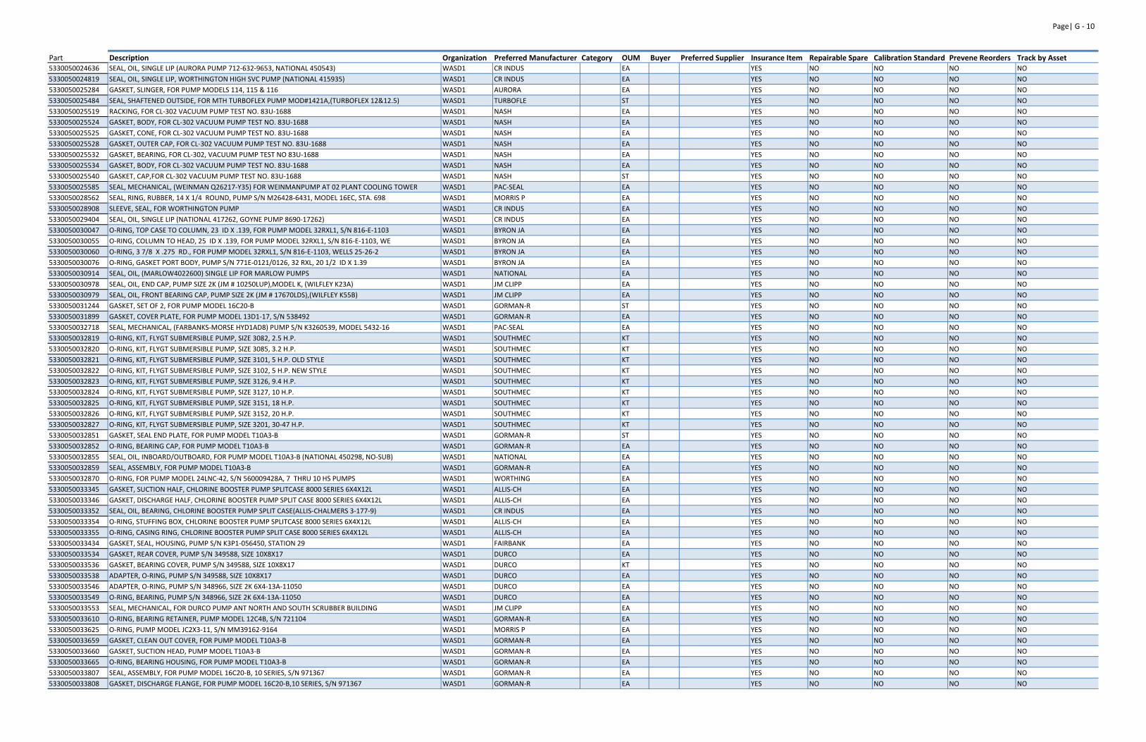
Page| G ‐ 10
Part Description Organization Preferred Manufacturer Category OUM Buyer Preferred Supplier Insurance Item Repairable Spare Calibration Standard Prevene Reorders Track by Asset5330050024636 SEAL, OIL, SINGLE LIP (AURORA PUMP 712‐632‐9653, NATIONAL 450543) WASD1 CR INDUS EA YES NO NO NO NO
5330050024819 SEAL, OIL, SINGLE LIP, WORTHINGTON HIGH SVC PUMP (NATIONAL 415935) WASD1 CR INDUS EA YES NO NO NO NO
5330050025284 GASKET, SLINGER, FOR PUMP MODELS 114, 115 & 116 WASD1 AURORA EA YES NO NO NO NO
5330050025484 SEAL, SHAFTENED OUTSIDE, FOR MTH TURBOFLEX PUMP MOD#1421A,(TURBOFLEX 12&12.5) WASD1 TURBOFLE ST YES NO NO NO NO
5330050025519 RACKING, FOR CL‐302 VACUUM PUMP TEST NO. 83U‐1688 WASD1 NASH EA YES NO NO NO NO
5330050025524 GASKET, BODY, FOR CL‐302 VACUUM PUMP TEST NO. 83U‐1688 WASD1 NASH EA YES NO NO NO NO
5330050025525 GASKET, CONE, FOR CL‐302 VACUUM PUMP TEST NO. 83U‐1688 WASD1 NASH EA YES NO NO NO NO
5330050025528 GASKET, OUTER CAP, FOR CL‐302 VACUUM PUMP TEST NO. 83U‐1688 WASD1 NASH EA YES NO NO NO NO
5330050025532 GASKET, BEARING, FOR CL‐302, VACUUM PUMP TEST NO 83U‐1688 WASD1 NASH EA YES NO NO NO NO
5330050025534 GASKET, BODY, FOR CL‐302 VACUUM PUMP TEST NO. 83U‐1688 WASD1 NASH EA YES NO NO NO NO
5330050025540 GASKET, CAP,FOR CL‐302 VACUUM PUMP TEST NO. 83U‐1688 WASD1 NASH ST YES NO NO NO NO
5330050025585 SEAL, MECHANICAL, (WEINMAN Q26217‐Y35) FOR WEINMANPUMP AT 02 PLANT COOLING TOWER WASD1 PAC‐SEAL EA YES NO NO NO NO
5330050028562 SEAL, RING, RUBBER, 14 X 1/4 ROUND, PUMP S/N M26428‐6431, MODEL 16EC, STA. 698 WASD1 MORRIS P EA YES NO NO NO NO
5330050028908 SLEEVE, SEAL, FOR WORTHINGTON PUMP WASD1 CR INDUS EA YES NO NO NO NO
5330050029404 SEAL, OIL, SINGLE LIP (NATIONAL 417262, GOYNE PUMP 8690‐17262) WASD1 CR INDUS EA YES NO NO NO NO
5330050030047 O‐RING, TOP CASE TO COLUMN, 23 ID X .139, FOR PUMP MODEL 32RXL1, S/N 816‐E‐1103 WASD1 BYRON JA EA YES NO NO NO NO
5330050030055 O‐RING, COLUMN TO HEAD, 25 ID X .139, FOR PUMP MODEL 32RXL1, S/N 816‐E‐1103, WE WASD1 BYRON JA EA YES NO NO NO NO
5330050030060 O‐RING, 3 7/8 X .275 RD., FOR PUMP MODEL 32RXL1, S/N 816‐E‐1103, WELLS 25‐26‐2 WASD1 BYRON JA EA YES NO NO NO NO
5330050030076 O‐RING, GASKET PORT BODY, PUMP S/N 771E‐0121/0126, 32 RXL, 20 1/2 ID X 1.39 WASD1 BYRON JA EA YES NO NO NO NO
5330050030914 SEAL, OIL, (MARLOW4022600) SINGLE LIP FOR MARLOW PUMPS WASD1 NATIONAL EA YES NO NO NO NO
5330050030978 SEAL, OIL, END CAP, PUMP SIZE 2K (JM # 10250LUP),MODEL K, (WILFLEY K23A) WASD1 JM CLIPP EA YES NO NO NO NO
5330050030979 SEAL, OIL, FRONT BEARING CAP, PUMP SIZE 2K (JM # 17670LDS),(WILFLEY K55B) WASD1 JM CLIPP EA YES NO NO NO NO
5330050031244 GASKET, SET OF 2, FOR PUMP MODEL 16C20‐B WASD1 GORMAN‐R ST YES NO NO NO NO
5330050031899 GASKET, COVER PLATE, FOR PUMP MODEL 13D1‐17, S/N 538492 WASD1 GORMAN‐R EA YES NO NO NO NO
5330050032718 SEAL, MECHANICAL, (FARBANKS‐MORSE HYD1AD8) PUMP S/N K3260539, MODEL 5432‐16 WASD1 PAC‐SEAL EA YES NO NO NO NO
5330050032819 O‐RING, KIT, FLYGT SUBMERSIBLE PUMP, SIZE 3082, 2.5 H.P. WASD1 SOUTHMEC KT YES NO NO NO NO
5330050032820 O‐RING, KIT, FLYGT SUBMERSIBLE PUMP, SIZE 3085, 3.2 H.P. WASD1 SOUTHMEC KT YES NO NO NO NO
5330050032821 O‐RING, KIT, FLYGT SUBMERSIBLE PUMP, SIZE 3101, 5 H.P. OLD STYLE WASD1 SOUTHMEC KT YES NO NO NO NO
5330050032822 O‐RING, KIT, FLYGT SUBMERSIBLE PUMP, SIZE 3102, 5 H.P. NEW STYLE WASD1 SOUTHMEC KT YES NO NO NO NO
5330050032823 O‐RING, KIT, FLYGT SUBMERSIBLE PUMP, SIZE 3126, 9.4 H.P. WASD1 SOUTHMEC KT YES NO NO NO NO
5330050032824 O‐RING, KIT, FLYGT SUBMERSIBLE PUMP, SIZE 3127, 10 H.P. WASD1 SOUTHMEC KT YES NO NO NO NO
5330050032825 O‐RING, KIT, FLYGT SUBMERSIBLE PUMP, SIZE 3151, 18 H.P. WASD1 SOUTHMEC KT YES NO NO NO NO
5330050032826 O‐RING, KIT, FLYGT SUBMERSIBLE PUMP, SIZE 3152, 20 H.P. WASD1 SOUTHMEC KT YES NO NO NO NO
5330050032827 O‐RING, KIT, FLYGT SUBMERSIBLE PUMP, SIZE 3201, 30‐47 H.P. WASD1 SOUTHMEC KT YES NO NO NO NO
5330050032851 GASKET, SEAL END PLATE, FOR PUMP MODEL T10A3‐B WASD1 GORMAN‐R ST YES NO NO NO NO
5330050032852 O‐RING, BEARING CAP, FOR PUMP MODEL T10A3‐B WASD1 GORMAN‐R EA YES NO NO NO NO
5330050032855 SEAL, OIL, INBOARD/OUTBOARD, FOR PUMP MODEL T10A3‐B (NATIONAL 450298, NO‐SUB) WASD1 NATIONAL EA YES NO NO NO NO
5330050032859 SEAL, ASSEMBLY, FOR PUMP MODEL T10A3‐B WASD1 GORMAN‐R EA YES NO NO NO NO
5330050032870 O‐RING, FOR PUMP MODEL 24LNC‐42, S/N 560009428A, 7 THRU 10 HS PUMPS WASD1 WORTHING EA YES NO NO NO NO
5330050033345 GASKET, SUCTION HALF, CHLORINE BOOSTER PUMP SPLITCASE 8000 SERIES 6X4X12L WASD1 ALLIS‐CH EA YES NO NO NO NO
5330050033346 GASKET, DISCHARGE HALF, CHLORINE BOOSTER PUMP SPLIT CASE 8000 SERIES 6X4X12L WASD1 ALLIS‐CH EA YES NO NO NO NO
5330050033352 SEAL, OIL, BEARING, CHLORINE BOOSTER PUMP SPLIT CASE(ALLIS‐CHALMERS 3‐177‐9) WASD1 CR INDUS EA YES NO NO NO NO
5330050033354 O‐RING, STUFFING BOX, CHLORINE BOOSTER PUMP SPLITCASE 8000 SERIES 6X4X12L WASD1 ALLIS‐CH EA YES NO NO NO NO
5330050033355 O‐RING, CASING RING, CHLORINE BOOSTER PUMP SPLIT CASE 8000 SERIES 6X4X12L WASD1 ALLIS‐CH EA YES NO NO NO NO
5330050033434 GASKET, SEAL, HOUSING, PUMP S/N K3P1‐056450, STATION 29 WASD1 FAIRBANK EA YES NO NO NO NO
5330050033534 GASKET, REAR COVER, PUMP S/N 349588, SIZE 10X8X17 WASD1 DURCO EA YES NO NO NO NO
5330050033536 GASKET, BEARING COVER, PUMP S/N 349588, SIZE 10X8X17 WASD1 DURCO KT YES NO NO NO NO
5330050033538 ADAPTER, O‐RING, PUMP S/N 349588, SIZE 10X8X17 WASD1 DURCO EA YES NO NO NO NO
5330050033546 ADAPTER, O‐RING, PUMP S/N 348966, SIZE 2K 6X4‐13A‐11050 WASD1 DURCO EA YES NO NO NO NO
5330050033549 O‐RING, BEARING, PUMP S/N 348966, SIZE 2K 6X4‐13A‐11050 WASD1 DURCO EA YES NO NO NO NO
5330050033553 SEAL, MECHANICAL, FOR DURCO PUMP ANT NORTH AND SOUTH SCRUBBER BUILDING WASD1 JM CLIPP EA YES NO NO NO NO
5330050033610 O‐RING, BEARING RETAINER, PUMP MODEL 12C4B, S/N 721104 WASD1 GORMAN‐R EA YES NO NO NO NO
5330050033625 O‐RING, PUMP MODEL JC2X3‐11, S/N MM39162‐9164 WASD1 MORRIS P EA YES NO NO NO NO
5330050033659 GASKET, CLEAN OUT COVER, FOR PUMP MODEL T10A3‐B WASD1 GORMAN‐R EA YES NO NO NO NO
5330050033660 GASKET, SUCTION HEAD, PUMP MODEL T10A3‐B WASD1 GORMAN‐R EA YES NO NO NO NO
5330050033665 O‐RING, BEARING HOUSING, FOR PUMP MODEL T10A3‐B WASD1 GORMAN‐R EA YES NO NO NO NO
5330050033807 SEAL, ASSEMBLY, FOR PUMP MODEL 16C20‐B, 10 SERIES, S/N 971367 WASD1 GORMAN‐R EA YES NO NO NO NO
5330050033808 GASKET, DISCHARGE FLANGE, FOR PUMP MODEL 16C20‐B,10 SERIES, S/N 971367 WASD1 GORMAN‐R EA YES NO NO NO NO
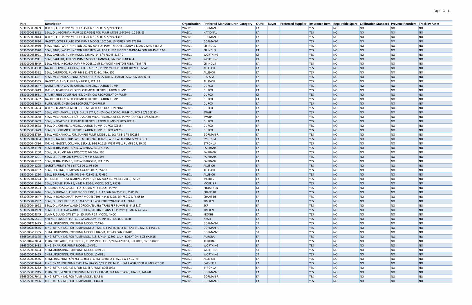
Page| G ‐ 11
Part Description Organization Preferred Manufacturer Category OUM Buyer Preferred Supplier Insurance Item Repairable Spare Calibration Standard Prevene Reorders Track by Asset5330050033809 O‐RING, FOR PUMP MODEL 16C20‐B, 10 SERIES, S/N 971367 WASD1 GORMAN‐R EA YES NO NO NO NO
5330050033812 SEAL, OIL, (GORMAN‐RUPP 25227‐534) FOR PUMP MODEL16C20‐B, 10 SERIES WASD1 NATIONAL EA YES NO NO NO NO
5330050033814 O‐RING, FOR PUMP MODEL 16C20‐B, 10 SERIES, S/N 971367 WASD1 GORMAN‐R EA YES NO NO NO NO
5330050033816 GASKET, COVER PLATE, FOR PUMP MODEL 16C20‐B, 10 SERIES, S/N 971367 WASD1 GORMAN‐R EA YES NO NO NO NO
5330050033919 SEAL, RING, (WORTHINGTON 007887‐00) FOR PUMP MODEL 12MNV‐14, S/N 78245‐8167‐2 WASD1 CR INDUS EA YES NO NO NO NO
5330050033920 SEAL, RING, (WORTHINGTON 7888 ITEM 47) FOR PUMP MODEL 12MNV‐14, S/N 78245‐8167‐2 WASD1 CR INDUS EA YES NO NO NO NO
5330050033921 SEAL, CAGE KIT, PUMP MODEL 12MNV‐14, S/N 78245‐8167‐2 WASD1 WORTHING KT YES NO NO NO NO
5330050033941 SEAL, CAGE KIT, TEFLON, PUMP MODEL 14MNV24, S/N 77ZUS‐8132‐4 WASD1 WORTHING KT YES NO NO NO NO
5330050033949 SEAL, RING, INBOARD, PUMP MODEL 10MF21 (WORTHINGTON 7889, ITEM 47) WASD1 CR INDUS EA YES NO NO NO NO
5330050034308 GASKET, COVER, SUCTION, FOR STA. 1073, PUMP MODEL150 10X10X21 LC‐N5W WASD1 ALLIS‐CH EA YES NO NO NO NO
5330050034332 SEAL, CARTRIDGE, PUMP S/N 811‐37332‐1‐1, STA. 156 WASD1 ALLIS‐CH EA YES NO NO NO NO
5330050034351 SEAL, MECHANICAL, PUMP S/N 87311, STA. 22 (ALLIS CHALMERS 52‐237‐805‐801) WASD1 U.S. SEA EA YES NO NO NO NO
5330050034355 GASKET, GLAND, PUMP S/N 87311, STA. 22 WASD1 ALLIS‐CH EA YES NO NO NO NO
5330050035647 GASKET, REAR COVER, CHEMICAL RECIRCULATION PUMP WASD1 DURCO EA YES NO NO NO NO
5330050035649 O‐RING, BEARING HOUSING, CHEMICAL RECIRCULATION PUMP WASD1 DURCO EA YES NO NO NO NO
5330050035651 KIT, BEARING COVER GASKET, CHEMICAL RECIRCULATIONPUMP WASD1 DURCO KT YES NO NO NO NO
5330050035662 GASKET, REAR COVER, CHEMICAL RECIRCULATION PUMP WASD1 DURCO EA YES NO NO NO NO
5330050035663 PLUG, VENT, CHEMICAL RECIRCULATION PUMP WASD1 DURCO EA YES NO NO NO NO
5330050035664 O‐RING, BEARING CARRIER, CHEMICAL RECIRCULATION PUMP WASD1 DURCO EA YES NO NO NO NO
5330050035667 SEAL, MECHANICAL, 1 7/8 DIA., 5 STAR, CHEMICAL RECIRC. PUMP(DURCO 1 7/8 SER 85) WASD1 BW/IP EA YES NO NO NO NO
5330050035668 SEAL, MECHANICAL, 1 3/8 DIA., CHEMICAL RECIRCULATION PUMP (DURCO 1 3/8 SER. 84) WASD1 BW/IP EA YES NO NO NO NO
5330050035669 SEAL, INBOARD OIL, CHEMICAL RECIRCULATION PUMP (DURCO 1K118) WASD1 DURCO EA YES NO NO NO NO
5330050035678 SEAL, OIL, CHEMICAL RECIRCULATION PUMP (DURCO 2Z118) WASD1 DURCO EA YES NO NO NO NO
5330050035679 SEAL, OIL, CHEMICAL RECIRCULATION PUMP (DURCO 2Z129) WASD1 DURCO EA YES NO NO NO NO
5330050035759 SEAL, MECHANICAL, FOR SAMPLE PUMP MODEL 11 1/2 A3‐B, S/N 900289 WASD1 GORMAN‐R EA YES NO NO NO NO
5330050040894 O‐RING, GASKET, TOP CASE, 32RXL1, 94‐ER‐1616, WEST WELL PUMPS 29, 30 ,31 WASD1 BYRON JA EA YES NO NO NO NO
5330050040896 O‐RING, GASKET, COLUMN, 32RXL1, 94‐ER‐1616, WEST WELL PUMPS 29, 30 ,31 WASD1 BYRON JA EA YES NO NO NO NO
5330050041189 SEAL, TETRA, PUMP S/N K3W1070757‐0, STA. 595 WASD1 FAIRBANK EA YES NO NO NO NO
5330050041200 SEAL, LIP, PUMP S/N K3W1070757‐0, STA. 595 WASD1 FAIRBANK EA YES NO NO NO NO
5330050041201 SEAL, LIP, PUMP S/N K3W1070757‐0, STA. 595 WASD1 FAIRBANK EA YES NO NO NO NO
5330050041202 SEAL, TETRA, PUMP S/N K3W1070757‐0, STA. 595 WASD1 FAIRBANK EA YES NO NO NO NO
5330050041205 GASKET, PUMP S/N 1‐64723‐01‐2, PS 690 WASD1 ALLIS‐CH EA YES NO NO NO NO
5330050041207 SEAL, BEARING, PUMP S/N 1‐64723‐01‐2, PS 690 WASD1 ALLIS‐CH EA YES NO NO NO NO
5330050041210 SEAL, BEARING, PUMP S/N 1‐64723‐01‐2, PS 690 WASD1 ALLIS‐CH EA YES NO NO NO NO
5330050041224 RETAINER, THRUST BEARING, PUMP S/N M27412‐16, MODEL 20EC, PS559 WASD1 MORRIS P EA YES NO NO NO NO
5330050041226 SEAL, GREASE, PUMP S/N M27412‐16, MODEL 20EC, PS559 WASD1 MORRIS P EA YES NO NO NO NO
5330050041594 KIT, DRIVE SEAL GASKET, FOR SIGMA NH3 FLUOR. PUMP WASD1 PROMINEN KT YES NO NO NO NO
5330050041646 SEAL, OUTBOARD, PUMP MODEL 7196, 4x4x12, S/N DP‐759171, PS 0510 WASD1 CRANE DE EA YES NO NO NO NO
5330050041647 SEAL, INBOARD SHAFT, PUMP MODEL 7196, 4x4x12, S/N DP‐759171, PS 0510 WASD1 CRANE DE EA YES NO NO NO NO
5330050041997 SEAL, OIL, DOUBLE DIP, 3.5 X 4.501 X 0.468, FOR DYNAMIC SEAL PUMP WASD1 TIMKEN EA YES NO NO NO NO
5330050041998 SEAL, OIL, FOR HAYWARD GORDON/SLURRY TRANSFER PUMPS (SKF 13812) WASD1 SKF EA YES NO NO NO NO
5330050041999 SEAL, OIL, FOR HAYWARD GORDON/SLURRY TRANSFER PUMPS (TIMKEN 471762) WASD1 TIMKEN EA YES NO NO NO NO
5340050014845 CLAMP, GLAND, S/N 87414‐15, PUMP 14 MODEL #NCC WASD1 KROGH EA YES NO NO NO NO
5360050025521 SPRING, TENSION, FOR CL‐302 VACUUM PUMP TEST NO.83U‐1688 WASD1 NASH EA YES NO NO NO NO
5365001722475 SHIM, ADJUSTING, FOR PUMP MODEL T6A3‐B WASD1 GORMAN‐R ST YES NO NO NO NO
5365002816655 RING, RETAINING, FOR PUMP MODELS T3A3‐B, T4A3‐B, T6A3‐B, T8A3‐B, 14A2‐B, 14A11‐B WASD1 GORMAN‐R EA YES NO NO NO NO
5365003617355 SHIM, ADJUSTING, FOR PUMP MODELS T8A3‐B, 12D‐13 (S/N 756206) WASD1 GORMAN‐R ST YES NO NO NO NO
5365004339825 RING, RETAINING, FOR PUMP MOD. 413, S/N 84‐12607‐1, L.H. ROTATION, SIZE 6X8X15 WASD1 AURORA EA YES NO NO NO NO
5365004673064 PLUG, THREADED, PROTECTOR, PUMP MOD. 413, S/N 84‐12607‐1, L.H. ROT., SIZE 6X8X15 WASD1 AURORA EA YES NO NO NO NO
5365050013438 RING, SNAP, FOR PUMP MODEL 10MF21 WASD1 WORTHING EA YES NO NO NO NO
5365050013454 SHIM, ADJUSTING, FOR PUMP MODEL 10MF21 WASD1 WORTHING ST YES NO NO NO NO
5365050013455 SHIM, ADJUSTING, FOR PUMP MODEL 10MF21 WASD1 WORTHING ST YES NO NO NO NO
5365050013546 SHIM, .015, PUMP S/N 761‐1938 8‐1‐1, 761‐19388‐2‐1, SIZE 6 X 4 X 12, M WASD1 ALLIS‐CH EA YES NO NO NO NO
5365050013684 RING, SNAP, FOR PUMP TYPE ETA 80‐250, S/N 112933‐491 HEAT EXCHANGER PUMP HOT CIR WASD1 CARVER P EA YES NO NO NO NO
5365050014232 RING, RETAINING, #334, FOR B.J. EFF. PUMP 806E1073 WASD1 BYRON JA EA YES NO NO NO NO
5365050017945 PLUG, PIPE, VENTED, FOR PUMP MODELS T3A3‐B, T4A3‐B, T6A3‐B, T8A3‐B, 14A2‐B WASD1 GORMAN‐R EA YES NO NO NO NO
5365050017948 RING, RETAINING, FOR PUMP MODEL T8A3‐B WASD1 GORMAN‐R EA YES NO NO NO NO
5365050017956 RING, RETAINING, FOR PUMP MODEL 13A2‐B WASD1 GORMAN‐R EA YES NO NO NO NO
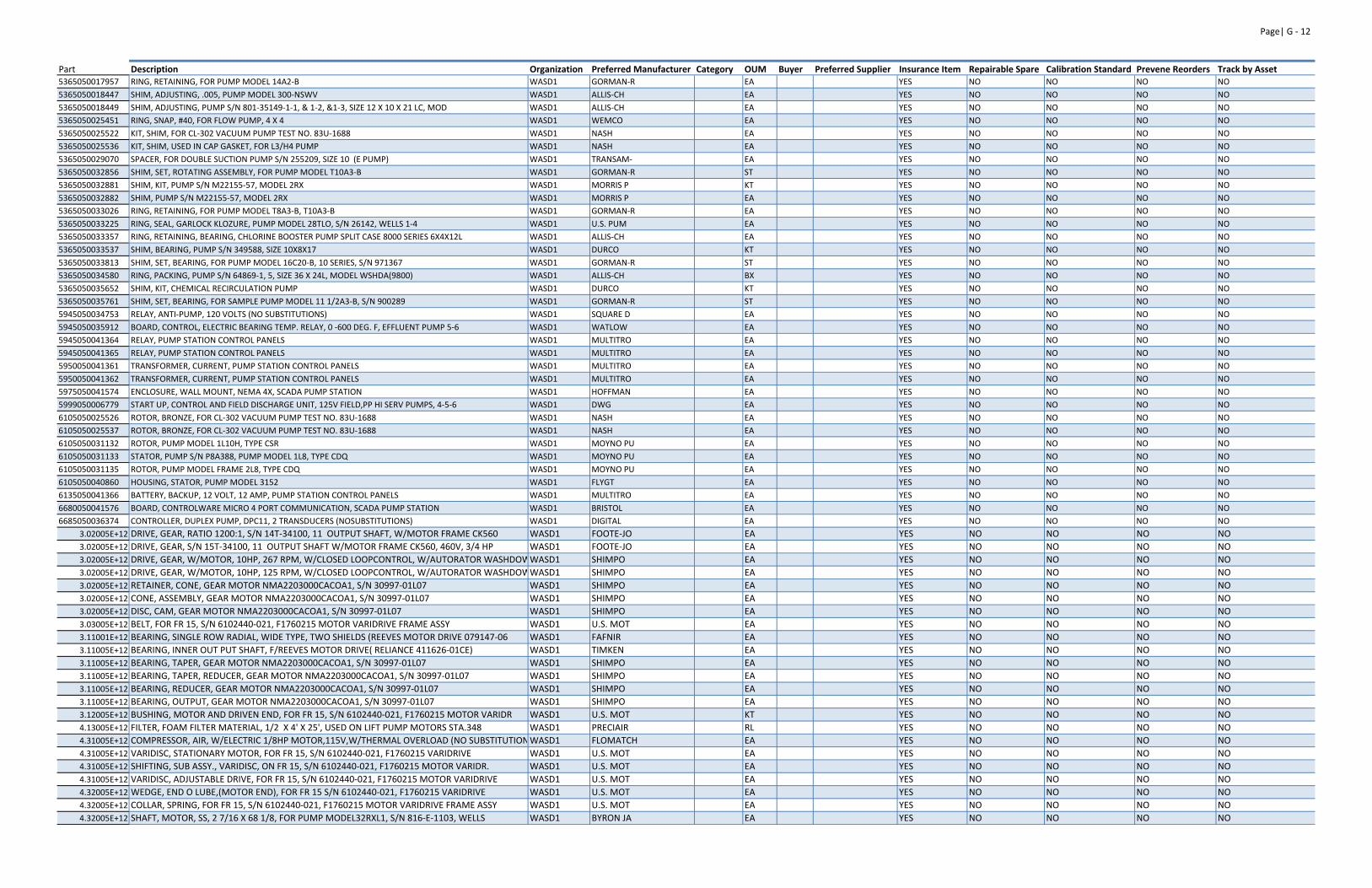
Page| G ‐ 12
Part Description Organization Preferred Manufacturer Category OUM Buyer Preferred Supplier Insurance Item Repairable Spare Calibration Standard Prevene Reorders Track by Asset5365050017957 RING, RETAINING, FOR PUMP MODEL 14A2‐B WASD1 GORMAN‐R EA YES NO NO NO NO
5365050018447 SHIM, ADJUSTING, .005, PUMP MODEL 300‐NSWV WASD1 ALLIS‐CH EA YES NO NO NO NO
5365050018449 SHIM, ADJUSTING, PUMP S/N 801‐35149‐1‐1, & 1‐2, &1‐3, SIZE 12 X 10 X 21 LC, MOD WASD1 ALLIS‐CH EA YES NO NO NO NO
5365050025451 RING, SNAP, #40, FOR FLOW PUMP, 4 X 4 WASD1 WEMCO EA YES NO NO NO NO
5365050025522 KIT, SHIM, FOR CL‐302 VACUUM PUMP TEST NO. 83U‐1688 WASD1 NASH EA YES NO NO NO NO
5365050025536 KIT, SHIM, USED IN CAP GASKET, FOR L3/H4 PUMP WASD1 NASH EA YES NO NO NO NO
5365050029070 SPACER, FOR DOUBLE SUCTION PUMP S/N 255209, SIZE 10 (E PUMP) WASD1 TRANSAM‐ EA YES NO NO NO NO
5365050032856 SHIM, SET, ROTATING ASSEMBLY, FOR PUMP MODEL T10A3‐B WASD1 GORMAN‐R ST YES NO NO NO NO
5365050032881 SHIM, KIT, PUMP S/N M22155‐57, MODEL 2RX WASD1 MORRIS P KT YES NO NO NO NO
5365050032882 SHIM, PUMP S/N M22155‐57, MODEL 2RX WASD1 MORRIS P EA YES NO NO NO NO
5365050033026 RING, RETAINING, FOR PUMP MODEL T8A3‐B, T10A3‐B WASD1 GORMAN‐R EA YES NO NO NO NO
5365050033225 RING, SEAL, GARLOCK KLOZURE, PUMP MODEL 28TLO, S/N 26142, WELLS 1‐4 WASD1 U.S. PUM EA YES NO NO NO NO
5365050033357 RING, RETAINING, BEARING, CHLORINE BOOSTER PUMP SPLIT CASE 8000 SERIES 6X4X12L WASD1 ALLIS‐CH EA YES NO NO NO NO
5365050033537 SHIM, BEARING, PUMP S/N 349588, SIZE 10X8X17 WASD1 DURCO KT YES NO NO NO NO
5365050033813 SHIM, SET, BEARING, FOR PUMP MODEL 16C20‐B, 10 SERIES, S/N 971367 WASD1 GORMAN‐R ST YES NO NO NO NO
5365050034580 RING, PACKING, PUMP S/N 64869‐1, 5, SIZE 36 X 24L, MODEL WSHDA(9800) WASD1 ALLIS‐CH BX YES NO NO NO NO
5365050035652 SHIM, KIT, CHEMICAL RECIRCULATION PUMP WASD1 DURCO KT YES NO NO NO NO
5365050035761 SHIM, SET, BEARING, FOR SAMPLE PUMP MODEL 11 1/2A3‐B, S/N 900289 WASD1 GORMAN‐R ST YES NO NO NO NO
5945050034753 RELAY, ANTI‐PUMP, 120 VOLTS (NO SUBSTITUTIONS) WASD1 SQUARE D EA YES NO NO NO NO
5945050035912 BOARD, CONTROL, ELECTRIC BEARING TEMP. RELAY, 0 ‐600 DEG. F, EFFLUENT PUMP 5‐6 WASD1 WATLOW EA YES NO NO NO NO
5945050041364 RELAY, PUMP STATION CONTROL PANELS WASD1 MULTITRO EA YES NO NO NO NO
5945050041365 RELAY, PUMP STATION CONTROL PANELS WASD1 MULTITRO EA YES NO NO NO NO
5950050041361 TRANSFORMER, CURRENT, PUMP STATION CONTROL PANELS WASD1 MULTITRO EA YES NO NO NO NO
5950050041362 TRANSFORMER, CURRENT, PUMP STATION CONTROL PANELS WASD1 MULTITRO EA YES NO NO NO NO
5975050041574 ENCLOSURE, WALL MOUNT, NEMA 4X, SCADA PUMP STATION WASD1 HOFFMAN EA YES NO NO NO NO
5999050006779 START UP, CONTROL AND FIELD DISCHARGE UNIT, 125V FIELD,PP HI SERV PUMPS, 4‐5‐6 WASD1 DWG EA YES NO NO NO NO
6105050025526 ROTOR, BRONZE, FOR CL‐302 VACUUM PUMP TEST NO. 83U‐1688 WASD1 NASH EA YES NO NO NO NO
6105050025537 ROTOR, BRONZE, FOR CL‐302 VACUUM PUMP TEST NO. 83U‐1688 WASD1 NASH EA YES NO NO NO NO
6105050031132 ROTOR, PUMP MODEL 1L10H, TYPE CSR WASD1 MOYNO PU EA YES NO NO NO NO
6105050031133 STATOR, PUMP S/N P8A388, PUMP MODEL 1L8, TYPE CDQ WASD1 MOYNO PU EA YES NO NO NO NO
6105050031135 ROTOR, PUMP MODEL FRAME 2L8, TYPE CDQ WASD1 MOYNO PU EA YES NO NO NO NO
6105050040860 HOUSING, STATOR, PUMP MODEL 3152 WASD1 FLYGT EA YES NO NO NO NO
6135050041366 BATTERY, BACKUP, 12 VOLT, 12 AMP, PUMP STATION CONTROL PANELS WASD1 MULTITRO EA YES NO NO NO NO
6680050041576 BOARD, CONTROLWARE MICRO 4 PORT COMMUNICATION, SCADA PUMP STATION WASD1 BRISTOL EA YES NO NO NO NO
6685050036374 CONTROLLER, DUPLEX PUMP, DPC11, 2 TRANSDUCERS (NOSUBSTITUTIONS) WASD1 DIGITAL EA YES NO NO NO NO
3.02005E+12 DRIVE, GEAR, RATIO 1200:1, S/N 14T‐34100, 11 OUTPUT SHAFT, W/MOTOR FRAME CK560 WASD1 FOOTE‐JO EA YES NO NO NO NO
3.02005E+12 DRIVE, GEAR, S/N 15T‐34100, 11 OUTPUT SHAFT W/MOTOR FRAME CK560, 460V, 3/4 HP WASD1 FOOTE‐JO EA YES NO NO NO NO
3.02005E+12 DRIVE, GEAR, W/MOTOR, 10HP, 267 RPM, W/CLOSED LOOPCONTROL, W/AUTORATOR WASHDOWWASD1 SHIMPO EA YES NO NO NO NO
3.02005E+12 DRIVE, GEAR, W/MOTOR, 10HP, 125 RPM, W/CLOSED LOOPCONTROL, W/AUTORATOR WASHDOWWASD1 SHIMPO EA YES NO NO NO NO
3.02005E+12 RETAINER, CONE, GEAR MOTOR NMA2203000CACOA1, S/N 30997‐01L07 WASD1 SHIMPO EA YES NO NO NO NO
3.02005E+12 CONE, ASSEMBLY, GEAR MOTOR NMA2203000CACOA1, S/N 30997‐01L07 WASD1 SHIMPO EA YES NO NO NO NO
3.02005E+12 DISC, CAM, GEAR MOTOR NMA2203000CACOA1, S/N 30997‐01L07 WASD1 SHIMPO EA YES NO NO NO NO
3.03005E+12 BELT, FOR FR 15, S/N 6102440‐021, F1760215 MOTOR VARIDRIVE FRAME ASSY WASD1 U.S. MOT EA YES NO NO NO NO
3.11001E+12 BEARING, SINGLE ROW RADIAL, WIDE TYPE, TWO SHIELDS (REEVES MOTOR DRIVE 079147‐06 WASD1 FAFNIR EA YES NO NO NO NO
3.11005E+12 BEARING, INNER OUT PUT SHAFT, F/REEVES MOTOR DRIVE( RELIANCE 411626‐01CE) WASD1 TIMKEN EA YES NO NO NO NO
3.11005E+12 BEARING, TAPER, GEAR MOTOR NMA2203000CACOA1, S/N 30997‐01L07 WASD1 SHIMPO EA YES NO NO NO NO
3.11005E+12 BEARING, TAPER, REDUCER, GEAR MOTOR NMA2203000CACOA1, S/N 30997‐01L07 WASD1 SHIMPO EA YES NO NO NO NO
3.11005E+12 BEARING, REDUCER, GEAR MOTOR NMA2203000CACOA1, S/N 30997‐01L07 WASD1 SHIMPO EA YES NO NO NO NO
3.11005E+12 BEARING, OUTPUT, GEAR MOTOR NMA2203000CACOA1, S/N 30997‐01L07 WASD1 SHIMPO EA YES NO NO NO NO
3.12005E+12 BUSHING, MOTOR AND DRIVEN END, FOR FR 15, S/N 6102440‐021, F1760215 MOTOR VARIDR WASD1 U.S. MOT KT YES NO NO NO NO
4.13005E+12 FILTER, FOAM FILTER MATERIAL, 1/2 X 4' X 25', USED ON LIFT PUMP MOTORS STA.348 WASD1 PRECIAIR RL YES NO NO NO NO
4.31005E+12 COMPRESSOR, AIR, W/ELECTRIC 1/8HP MOTOR,115V,W/THERMAL OVERLOAD (NO SUBSTITUTIONWASD1 FLOMATCH EA YES NO NO NO NO
4.31005E+12 VARIDISC, STATIONARY MOTOR, FOR FR 15, S/N 6102440‐021, F1760215 VARIDRIVE WASD1 U.S. MOT EA YES NO NO NO NO
4.31005E+12 SHIFTING, SUB ASSY., VARIDISC, ON FR 15, S/N 6102440‐021, F1760215 MOTOR VARIDR. WASD1 U.S. MOT EA YES NO NO NO NO
4.31005E+12 VARIDISC, ADJUSTABLE DRIVE, FOR FR 15, S/N 6102440‐021, F1760215 MOTOR VARIDRIVE WASD1 U.S. MOT EA YES NO NO NO NO
4.32005E+12 WEDGE, END O LUBE,(MOTOR END), FOR FR 15 S/N 6102440‐021, F1760215 VARIDRIVE WASD1 U.S. MOT EA YES NO NO NO NO
4.32005E+12 COLLAR, SPRING, FOR FR 15, S/N 6102440‐021, F1760215 MOTOR VARIDRIVE FRAME ASSY WASD1 U.S. MOT EA YES NO NO NO NO
4.32005E+12 SHAFT, MOTOR, SS, 2 7/16 X 68 1/8, FOR PUMP MODEL32RXL1, S/N 816‐E‐1103, WELLS WASD1 BYRON JA EA YES NO NO NO NO
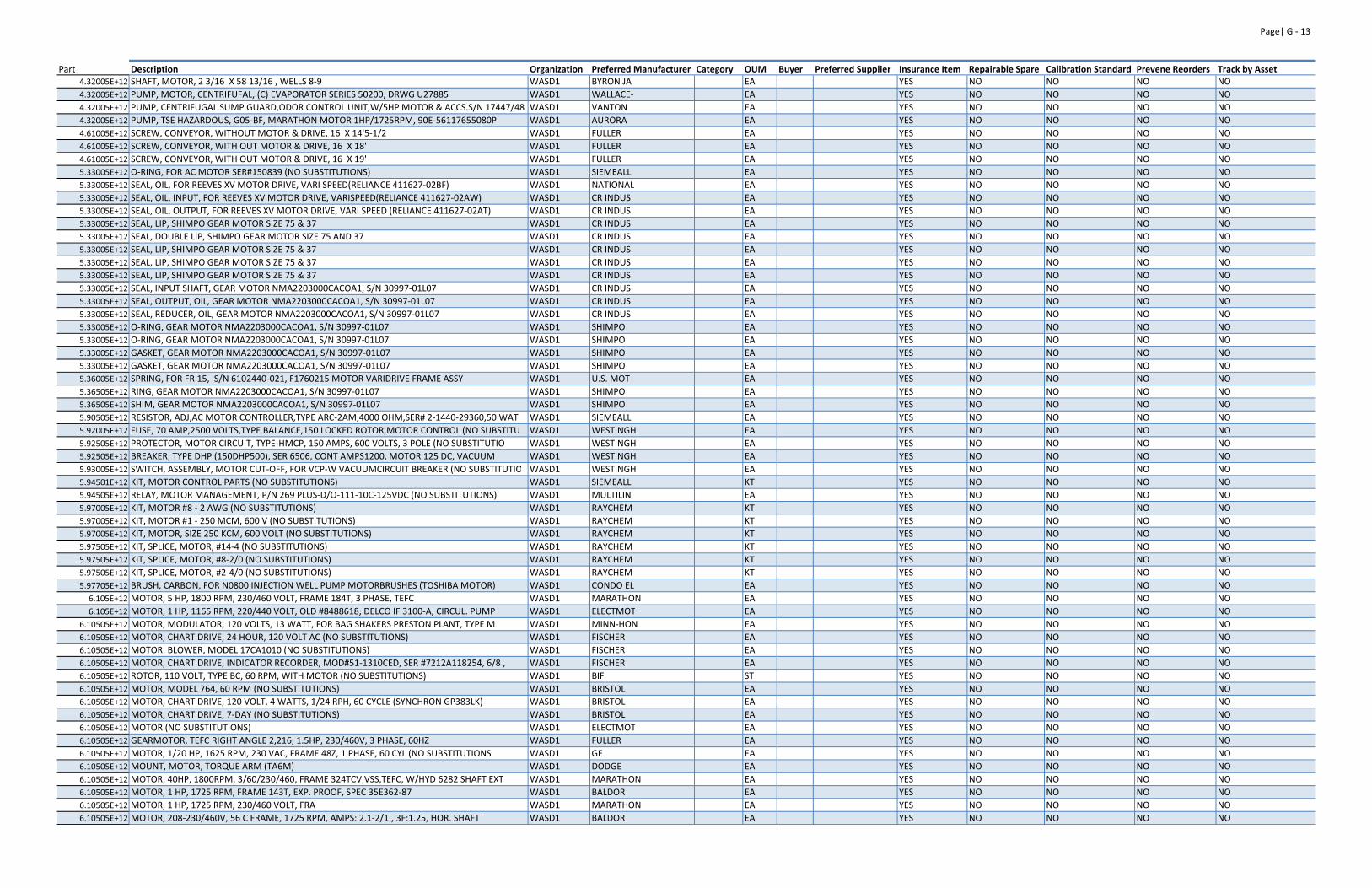
Page| G ‐ 13
Part Description Organization Preferred Manufacturer Category OUM Buyer Preferred Supplier Insurance Item Repairable Spare Calibration Standard Prevene Reorders Track by Asset4.32005E+12 SHAFT, MOTOR, 2 3/16 X 58 13/16 , WELLS 8‐9 WASD1 BYRON JA EA YES NO NO NO NO
4.32005E+12 PUMP, MOTOR, CENTRIFUFAL, (C) EVAPORATOR SERIES 50200, DRWG U27885 WASD1 WALLACE‐ EA YES NO NO NO NO
4.32005E+12 PUMP, CENTRIFUGAL SUMP GUARD,ODOR CONTROL UNIT,W/5HP MOTOR & ACCS.S/N 17447/48 WASD1 VANTON EA YES NO NO NO NO
4.32005E+12 PUMP, TSE HAZARDOUS, G05‐BF, MARATHON MOTOR 1HP/1725RPM, 90E‐56117655080P WASD1 AURORA EA YES NO NO NO NO
4.61005E+12 SCREW, CONVEYOR, WITHOUT MOTOR & DRIVE, 16 X 14'5‐1/2 WASD1 FULLER EA YES NO NO NO NO
4.61005E+12 SCREW, CONVEYOR, WITH OUT MOTOR & DRIVE, 16 X 18' WASD1 FULLER EA YES NO NO NO NO
4.61005E+12 SCREW, CONVEYOR, WITH OUT MOTOR & DRIVE, 16 X 19' WASD1 FULLER EA YES NO NO NO NO
5.33005E+12 O‐RING, FOR AC MOTOR SER#150839 (NO SUBSTITUTIONS) WASD1 SIEMEALL EA YES NO NO NO NO
5.33005E+12 SEAL, OIL, FOR REEVES XV MOTOR DRIVE, VARI SPEED(RELIANCE 411627‐02BF) WASD1 NATIONAL EA YES NO NO NO NO
5.33005E+12 SEAL, OIL, INPUT, FOR REEVES XV MOTOR DRIVE, VARISPEED(RELIANCE 411627‐02AW) WASD1 CR INDUS EA YES NO NO NO NO
5.33005E+12 SEAL, OIL, OUTPUT, FOR REEVES XV MOTOR DRIVE, VARI SPEED (RELIANCE 411627‐02AT) WASD1 CR INDUS EA YES NO NO NO NO
5.33005E+12 SEAL, LIP, SHIMPO GEAR MOTOR SIZE 75 & 37 WASD1 CR INDUS EA YES NO NO NO NO
5.33005E+12 SEAL, DOUBLE LIP, SHIMPO GEAR MOTOR SIZE 75 AND 37 WASD1 CR INDUS EA YES NO NO NO NO
5.33005E+12 SEAL, LIP, SHIMPO GEAR MOTOR SIZE 75 & 37 WASD1 CR INDUS EA YES NO NO NO NO
5.33005E+12 SEAL, LIP, SHIMPO GEAR MOTOR SIZE 75 & 37 WASD1 CR INDUS EA YES NO NO NO NO
5.33005E+12 SEAL, LIP, SHIMPO GEAR MOTOR SIZE 75 & 37 WASD1 CR INDUS EA YES NO NO NO NO
5.33005E+12 SEAL, INPUT SHAFT, GEAR MOTOR NMA2203000CACOA1, S/N 30997‐01L07 WASD1 CR INDUS EA YES NO NO NO NO
5.33005E+12 SEAL, OUTPUT, OIL, GEAR MOTOR NMA2203000CACOA1, S/N 30997‐01L07 WASD1 CR INDUS EA YES NO NO NO NO
5.33005E+12 SEAL, REDUCER, OIL, GEAR MOTOR NMA2203000CACOA1, S/N 30997‐01L07 WASD1 CR INDUS EA YES NO NO NO NO
5.33005E+12 O‐RING, GEAR MOTOR NMA2203000CACOA1, S/N 30997‐01L07 WASD1 SHIMPO EA YES NO NO NO NO
5.33005E+12 O‐RING, GEAR MOTOR NMA2203000CACOA1, S/N 30997‐01L07 WASD1 SHIMPO EA YES NO NO NO NO
5.33005E+12 GASKET, GEAR MOTOR NMA2203000CACOA1, S/N 30997‐01L07 WASD1 SHIMPO EA YES NO NO NO NO
5.33005E+12 GASKET, GEAR MOTOR NMA2203000CACOA1, S/N 30997‐01L07 WASD1 SHIMPO EA YES NO NO NO NO
5.36005E+12 SPRING, FOR FR 15, S/N 6102440‐021, F1760215 MOTOR VARIDRIVE FRAME ASSY WASD1 U.S. MOT EA YES NO NO NO NO
5.36505E+12 RING, GEAR MOTOR NMA2203000CACOA1, S/N 30997‐01L07 WASD1 SHIMPO EA YES NO NO NO NO
5.36505E+12 SHIM, GEAR MOTOR NMA2203000CACOA1, S/N 30997‐01L07 WASD1 SHIMPO EA YES NO NO NO NO
5.90505E+12 RESISTOR, ADJ,AC MOTOR CONTROLLER,TYPE ARC‐2AM,4000 OHM,SER# 2‐1440‐29360,50 WAT WASD1 SIEMEALL EA YES NO NO NO NO
5.92005E+12 FUSE, 70 AMP,2500 VOLTS,TYPE BALANCE,150 LOCKED ROTOR,MOTOR CONTROL (NO SUBSTITU WASD1 WESTINGH EA YES NO NO NO NO
5.92505E+12 PROTECTOR, MOTOR CIRCUIT, TYPE‐HMCP, 150 AMPS, 600 VOLTS, 3 POLE (NO SUBSTITUTIO WASD1 WESTINGH EA YES NO NO NO NO
5.92505E+12 BREAKER, TYPE DHP (150DHP500), SER 6506, CONT AMPS1200, MOTOR 125 DC, VACUUM WASD1 WESTINGH EA YES NO NO NO NO
5.93005E+12 SWITCH, ASSEMBLY, MOTOR CUT‐OFF, FOR VCP‐W VACUUMCIRCUIT BREAKER (NO SUBSTITUTIO WASD1 WESTINGH EA YES NO NO NO NO
5.94501E+12 KIT, MOTOR CONTROL PARTS (NO SUBSTITUTIONS) WASD1 SIEMEALL KT YES NO NO NO NO
5.94505E+12 RELAY, MOTOR MANAGEMENT, P/N 269 PLUS‐D/O‐111‐10C‐125VDC (NO SUBSTITUTIONS) WASD1 MULTILIN EA YES NO NO NO NO
5.97005E+12 KIT, MOTOR #8 ‐ 2 AWG (NO SUBSTITUTIONS) WASD1 RAYCHEM KT YES NO NO NO NO
5.97005E+12 KIT, MOTOR #1 ‐ 250 MCM, 600 V (NO SUBSTITUTIONS) WASD1 RAYCHEM KT YES NO NO NO NO
5.97005E+12 KIT, MOTOR, SIZE 250 KCM, 600 VOLT (NO SUBSTITUTIONS) WASD1 RAYCHEM KT YES NO NO NO NO
5.97505E+12 KIT, SPLICE, MOTOR, #14‐4 (NO SUBSTITUTIONS) WASD1 RAYCHEM KT YES NO NO NO NO
5.97505E+12 KIT, SPLICE, MOTOR, #8‐2/0 (NO SUBSTITUTIONS) WASD1 RAYCHEM KT YES NO NO NO NO
5.97505E+12 KIT, SPLICE, MOTOR, #2‐4/0 (NO SUBSTITUTIONS) WASD1 RAYCHEM KT YES NO NO NO NO
5.97705E+12 BRUSH, CARBON, FOR N0800 INJECTION WELL PUMP MOTORBRUSHES (TOSHIBA MOTOR) WASD1 CONDO EL EA YES NO NO NO NO
6.105E+12 MOTOR, 5 HP, 1800 RPM, 230/460 VOLT, FRAME 184T, 3 PHASE, TEFC WASD1 MARATHON EA YES NO NO NO NO
6.105E+12 MOTOR, 1 HP, 1165 RPM, 220/440 VOLT, OLD #8488618, DELCO IF 3100‐A, CIRCUL. PUMP WASD1 ELECTMOT EA YES NO NO NO NO
6.10505E+12 MOTOR, MODULATOR, 120 VOLTS, 13 WATT, FOR BAG SHAKERS PRESTON PLANT, TYPE M WASD1 MINN‐HON EA YES NO NO NO NO
6.10505E+12 MOTOR, CHART DRIVE, 24 HOUR, 120 VOLT AC (NO SUBSTITUTIONS) WASD1 FISCHER EA YES NO NO NO NO
6.10505E+12 MOTOR, BLOWER, MODEL 17CA1010 (NO SUBSTITUTIONS) WASD1 FISCHER EA YES NO NO NO NO
6.10505E+12 MOTOR, CHART DRIVE, INDICATOR RECORDER, MOD#51‐1310CED, SER #7212A118254, 6/8 , WASD1 FISCHER EA YES NO NO NO NO
6.10505E+12 ROTOR, 110 VOLT, TYPE BC, 60 RPM, WITH MOTOR (NO SUBSTITUTIONS) WASD1 BIF ST YES NO NO NO NO
6.10505E+12 MOTOR, MODEL 764, 60 RPM (NO SUBSTITUTIONS) WASD1 BRISTOL EA YES NO NO NO NO
6.10505E+12 MOTOR, CHART DRIVE, 120 VOLT, 4 WATTS, 1/24 RPH, 60 CYCLE (SYNCHRON GP383LK) WASD1 BRISTOL EA YES NO NO NO NO
6.10505E+12 MOTOR, CHART DRIVE, 7‐DAY (NO SUBSTITUTIONS) WASD1 BRISTOL EA YES NO NO NO NO
6.10505E+12 MOTOR (NO SUBSTITUTIONS) WASD1 ELECTMOT EA YES NO NO NO NO
6.10505E+12 GEARMOTOR, TEFC RIGHT ANGLE 2,216, 1.5HP, 230/460V, 3 PHASE, 60HZ WASD1 FULLER EA YES NO NO NO NO
6.10505E+12 MOTOR, 1/20 HP, 1625 RPM, 230 VAC, FRAME 48Z, 1 PHASE, 60 CYL (NO SUBSTITUTIONS WASD1 GE EA YES NO NO NO NO
6.10505E+12 MOUNT, MOTOR, TORQUE ARM (TA6M) WASD1 DODGE EA YES NO NO NO NO
6.10505E+12 MOTOR, 40HP, 1800RPM, 3/60/230/460, FRAME 324TCV,VSS,TEFC, W/HYD 6282 SHAFT EXT WASD1 MARATHON EA YES NO NO NO NO
6.10505E+12 MOTOR, 1 HP, 1725 RPM, FRAME 143T, EXP. PROOF, SPEC 35E362‐87 WASD1 BALDOR EA YES NO NO NO NO
6.10505E+12 MOTOR, 1 HP, 1725 RPM, 230/460 VOLT, FRA WASD1 MARATHON EA YES NO NO NO NO
6.10505E+12 MOTOR, 208‐230/460V, 56 C FRAME, 1725 RPM, AMPS: 2.1‐2/1., 3F:1.25, HOR. SHAFT WASD1 BALDOR EA YES NO NO NO NO
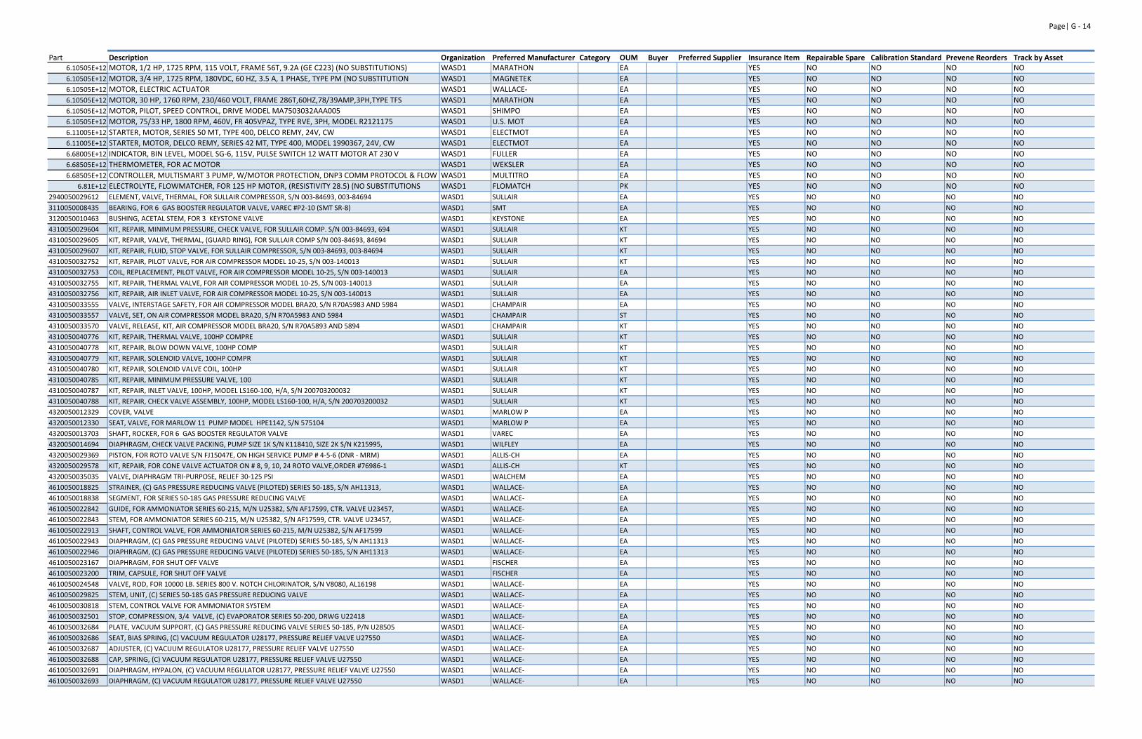
Page| G ‐ 14
Part Description Organization Preferred Manufacturer Category OUM Buyer Preferred Supplier Insurance Item Repairable Spare Calibration Standard Prevene Reorders Track by Asset6.10505E+12 MOTOR, 1/2 HP, 1725 RPM, 115 VOLT, FRAME 56T, 9.2A (GE C223) (NO SUBSTITUTIONS) WASD1 MARATHON EA YES NO NO NO NO
6.10505E+12 MOTOR, 3/4 HP, 1725 RPM, 180VDC, 60 HZ, 3.5 A, 1 PHASE, TYPE PM (NO SUBSTITUTION WASD1 MAGNETEK EA YES NO NO NO NO
6.10505E+12 MOTOR, ELECTRIC ACTUATOR WASD1 WALLACE‐ EA YES NO NO NO NO
6.10505E+12 MOTOR, 30 HP, 1760 RPM, 230/460 VOLT, FRAME 286T,60HZ,78/39AMP,3PH,TYPE TFS WASD1 MARATHON EA YES NO NO NO NO
6.10505E+12 MOTOR, PILOT, SPEED CONTROL, DRIVE MODEL MA7503032AAA005 WASD1 SHIMPO EA YES NO NO NO NO
6.10505E+12 MOTOR, 75/33 HP, 1800 RPM, 460V, FR 405VPAZ, TYPE RVE, 3PH, MODEL R2121175 WASD1 U.S. MOT EA YES NO NO NO NO
6.11005E+12 STARTER, MOTOR, SERIES 50 MT, TYPE 400, DELCO REMY, 24V, CW WASD1 ELECTMOT EA YES NO NO NO NO
6.11005E+12 STARTER, MOTOR, DELCO REMY, SERIES 42 MT, TYPE 400, MODEL 1990367, 24V, CW WASD1 ELECTMOT EA YES NO NO NO NO
6.68005E+12 INDICATOR, BIN LEVEL, MODEL SG‐6, 115V, PULSE SWITCH 12 WATT MOTOR AT 230 V WASD1 FULLER EA YES NO NO NO NO
6.68505E+12 THERMOMETER, FOR AC MOTOR WASD1 WEKSLER EA YES NO NO NO NO
6.68505E+12 CONTROLLER, MULTISMART 3 PUMP, W/MOTOR PROTECTION, DNP3 COMM PROTOCOL & FLOW WASD1 MULTITRO EA YES NO NO NO NO
6.81E+12 ELECTROLYTE, FLOWMATCHER, FOR 125 HP MOTOR, (RESISTIVITY 28.5) (NO SUBSTITUTIONS WASD1 FLOMATCH PK YES NO NO NO NO
2940050029612 ELEMENT, VALVE, THERMAL, FOR SULLAIR COMPRESSOR, S/N 003‐84693, 003‐84694 WASD1 SULLAIR EA YES NO NO NO NO
3110050008435 BEARING, FOR 6 GAS BOOSTER REGULATOR VALVE, VAREC #P2‐10 (SMT SR‐8) WASD1 SMT EA YES NO NO NO NO
3120050010463 BUSHING, ACETAL STEM, FOR 3 KEYSTONE VALVE WASD1 KEYSTONE EA YES NO NO NO NO
4310050029604 KIT, REPAIR, MINIMUM PRESSURE, CHECK VALVE, FOR SULLAIR COMP. S/N 003‐84693, 694 WASD1 SULLAIR KT YES NO NO NO NO
4310050029605 KIT, REPAIR, VALVE, THERMAL, (GUARD RING), FOR SULLAIR COMP S/N 003‐84693, 84694 WASD1 SULLAIR KT YES NO NO NO NO
4310050029607 KIT, REPAIR, FLUID, STOP VALVE, FOR SULLAIR COMPRESSOR, S/N 003‐84693, 003‐84694 WASD1 SULLAIR KT YES NO NO NO NO
4310050032752 KIT, REPAIR, PILOT VALVE, FOR AIR COMPRESSOR MODEL 10‐25, S/N 003‐140013 WASD1 SULLAIR KT YES NO NO NO NO
4310050032753 COIL, REPLACEMENT, PILOT VALVE, FOR AIR COMPRESSOR MODEL 10‐25, S/N 003‐140013 WASD1 SULLAIR EA YES NO NO NO NO
4310050032755 KIT, REPAIR, THERMAL VALVE, FOR AIR COMPRESSOR MODEL 10‐25, S/N 003‐140013 WASD1 SULLAIR EA YES NO NO NO NO
4310050032756 KIT, REPAIR, AIR INLET VALVE, FOR AIR COMPRESSOR MODEL 10‐25, S/N 003‐140013 WASD1 SULLAIR EA YES NO NO NO NO
4310050033555 VALVE, INTERSTAGE SAFETY, FOR AIR COMPRESSOR MODEL BRA20, S/N R70A5983 AND 5984 WASD1 CHAMPAIR EA YES NO NO NO NO
4310050033557 VALVE, SET, ON AIR COMPRESSOR MODEL BRA20, S/N R70A5983 AND 5984 WASD1 CHAMPAIR ST YES NO NO NO NO
4310050033570 VALVE, RELEASE, KIT, AIR COMPRESSOR MODEL BRA20, S/N R70A5893 AND 5894 WASD1 CHAMPAIR KT YES NO NO NO NO
4310050040776 KIT, REPAIR, THERMAL VALVE, 100HP COMPRE WASD1 SULLAIR KT YES NO NO NO NO
4310050040778 KIT, REPAIR, BLOW DOWN VALVE, 100HP COMP WASD1 SULLAIR KT YES NO NO NO NO
4310050040779 KIT, REPAIR, SOLENOID VALVE, 100HP COMPR WASD1 SULLAIR KT YES NO NO NO NO
4310050040780 KIT, REPAIR, SOLENOID VALVE COIL, 100HP WASD1 SULLAIR KT YES NO NO NO NO
4310050040785 KIT, REPAIR, MINIMUM PRESSURE VALVE, 100 WASD1 SULLAIR KT YES NO NO NO NO
4310050040787 KIT, REPAIR, INLET VALVE, 100HP, MODEL LS160‐100, H/A, S/N 200703200032 WASD1 SULLAIR KT YES NO NO NO NO
4310050040788 KIT, REPAIR, CHECK VALVE ASSEMBLY, 100HP, MODEL LS160‐100, H/A, S/N 200703200032 WASD1 SULLAIR KT YES NO NO NO NO
4320050012329 COVER, VALVE WASD1 MARLOW P EA YES NO NO NO NO
4320050012330 SEAT, VALVE, FOR MARLOW 11 PUMP MODEL HPE1142, S/N 575104 WASD1 MARLOW P EA YES NO NO NO NO
4320050013703 SHAFT, ROCKER, FOR 6 GAS BOOSTER REGULATOR VALVE WASD1 VAREC EA YES NO NO NO NO
4320050014694 DIAPHRAGM, CHECK VALVE PACKING, PUMP SIZE 1K S/N K118410, SIZE 2K S/N K215995, WASD1 WILFLEY EA YES NO NO NO NO
4320050029369 PISTON, FOR ROTO VALVE S/N FJ15047E, ON HIGH SERVICE PUMP # 4‐5‐6 (DNR ‐ MRM) WASD1 ALLIS‐CH EA YES NO NO NO NO
4320050029578 KIT, REPAIR, FOR CONE VALVE ACTUATOR ON # 8, 9, 10, 24 ROTO VALVE,ORDER #76986‐1 WASD1 ALLIS‐CH KT YES NO NO NO NO
4320050035035 VALVE, DIAPHRAGM TRI‐PURPOSE, RELIEF 30‐125 PSI WASD1 WALCHEM EA YES NO NO NO NO
4610050018825 STRAINER, (C) GAS PRESSURE REDUCING VALVE (PILOTED) SERIES 50‐185, S/N AH11313, WASD1 WALLACE‐ EA YES NO NO NO NO
4610050018838 SEGMENT, FOR SERIES 50‐185 GAS PRESSURE REDUCING VALVE WASD1 WALLACE‐ EA YES NO NO NO NO
4610050022842 GUIDE, FOR AMMONIATOR SERIES 60‐215, M/N U25382, S/N AF17599, CTR. VALVE U23457, WASD1 WALLACE‐ EA YES NO NO NO NO
4610050022843 STEM, FOR AMMONIATOR SERIES 60‐215, M/N U25382, S/N AF17599, CTR. VALVE U23457, WASD1 WALLACE‐ EA YES NO NO NO NO
4610050022913 SHAFT, CONTROL VALVE, FOR AMMONIATOR SERIES 60‐215, M/N U25382, S/N AF17599 WASD1 WALLACE‐ EA YES NO NO NO NO
4610050022943 DIAPHRAGM, (C) GAS PRESSURE REDUCING VALVE (PILOTED) SERIES 50‐185, S/N AH11313 WASD1 WALLACE‐ EA YES NO NO NO NO
4610050022946 DIAPHRAGM, (C) GAS PRESSURE REDUCING VALVE (PILOTED) SERIES 50‐185, S/N AH11313 WASD1 WALLACE‐ EA YES NO NO NO NO
4610050023167 DIAPHRAGM, FOR SHUT OFF VALVE WASD1 FISCHER EA YES NO NO NO NO
4610050023200 TRIM, CAPSULE, FOR SHUT OFF VALVE WASD1 FISCHER EA YES NO NO NO NO
4610050024548 VALVE, ROD, FOR 10000 LB. SERIES 800 V. NOTCH CHLORINATOR, S/N V8080, AL16198 WASD1 WALLACE‐ EA YES NO NO NO NO
4610050029825 STEM, UNIT, (C) SERIES 50‐185 GAS PRESSURE REDUCING VALVE WASD1 WALLACE‐ EA YES NO NO NO NO
4610050030818 STEM, CONTROL VALVE FOR AMMONIATOR SYSTEM WASD1 WALLACE‐ EA YES NO NO NO NO
4610050032501 STOP, COMPRESSION, 3/4 VALVE, (C) EVAPORATOR SERIES 50‐200, DRWG U22418 WASD1 WALLACE‐ EA YES NO NO NO NO
4610050032684 PLATE, VACUUM SUPPORT, (C) GAS PRESSURE REDUCING VALVE SERIES 50‐185, P/N U28505 WASD1 WALLACE‐ EA YES NO NO NO NO
4610050032686 SEAT, BIAS SPRING, (C) VACUUM REGULATOR U28177, PRESSURE RELIEF VALVE U27550 WASD1 WALLACE‐ EA YES NO NO NO NO
4610050032687 ADJUSTER, (C) VACUUM REGULATOR U28177, PRESSURE RELIEF VALVE U27550 WASD1 WALLACE‐ EA YES NO NO NO NO
4610050032688 CAP, SPRING, (C) VACUUM REGULATOR U28177, PRESSURE RELIEF VALVE U27550 WASD1 WALLACE‐ EA YES NO NO NO NO
4610050032691 DIAPHRAGM, HYPALON, (C) VACUUM REGULATOR U28177, PRESSURE RELIEF VALVE U27550 WASD1 WALLACE‐ EA YES NO NO NO NO
4610050032693 DIAPHRAGM, (C) VACUUM REGULATOR U28177, PRESSURE RELIEF VALVE U27550 WASD1 WALLACE‐ EA YES NO NO NO NO
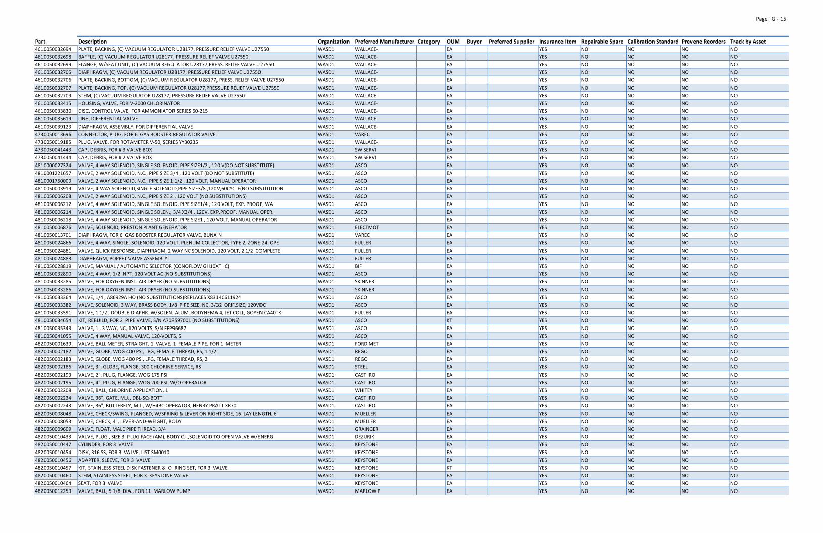
Page| G ‐ 15
Part Description Organization Preferred Manufacturer Category OUM Buyer Preferred Supplier Insurance Item Repairable Spare Calibration Standard Prevene Reorders Track by Asset4610050032694 PLATE, BACKING, (C) VACUUM REGULATOR U28177, PRESSURE RELIEF VALVE U27550 WASD1 WALLACE‐ EA YES NO NO NO NO
4610050032698 BAFFLE, (C) VACUUM REGULATOR U28177, PRESSURE RELIEF VALVE U27550 WASD1 WALLACE‐ EA YES NO NO NO NO
4610050032699 FLANGE, W/SEAT UNIT, (C) VACUUM REGULATOR U28177,PRESS. RELIEF VALVE U27550 WASD1 WALLACE‐ EA YES NO NO NO NO
4610050032705 DIAPHRAGM, (C) VACUUM REGULATOR U28177, PRESSURE RELIEF VALVE U27550 WASD1 WALLACE‐ EA YES NO NO NO NO
4610050032706 PLATE, BACKING, BOTTOM, (C) VACUUM REGULATOR U28177, PRESS. RELIEF VALVE U27550 WASD1 WALLACE‐ EA YES NO NO NO NO
4610050032707 PLATE, BACKING, TOP, (C) VACUUM REGULATOR U28177,PRESSURE RELIEF VALVE U27550 WASD1 WALLACE‐ EA YES NO NO NO NO
4610050032709 STEM, (C) VACUUM REGULATOR U28177, PRESSURE RELIEF VALVE U27550 WASD1 WALLACE‐ EA YES NO NO NO NO
4610050033415 HOUSING, VALVE, FOR V‐2000 CHLORINATOR WASD1 WALLACE‐ EA YES NO NO NO NO
4610050033830 DISC, CONTROL VALVE, FOR AMMONIATOR SERIES 60‐215 WASD1 WALLACE‐ EA YES NO NO NO NO
4610050035619 LINE, DIFFERENTIAL VALVE WASD1 WALLACE‐ EA YES NO NO NO NO
4610050039123 DIAPHRAGM, ASSEMBLY, FOR DIFFERENTIAL VALVE WASD1 WALLACE‐ EA YES NO NO NO NO
4730050013696 CONNECTOR, PLUG, FOR 6 GAS BOOSTER REGULATOR VALVE WASD1 VAREC EA YES NO NO NO NO
4730050019185 PLUG, VALVE, FOR ROTAMETER V‐50, SERIES YY30235 WASD1 WALLACE‐ EA YES NO NO NO NO
4730050041443 CAP, DEBRIS, FOR # 3 VALVE BOX WASD1 SW SERVI EA YES NO NO NO NO
4730050041444 CAP, DEBRIS, FOR # 2 VALVE BOX WASD1 SW SERVI EA YES NO NO NO NO
4810000027324 VALVE, 4 WAY SOLENOID, SINGLE SOLENOID, PIPE SIZE1/2 , 120 V(DO NOT SUBSTITUTE) WASD1 ASCO EA YES NO NO NO NO
4810001221657 VALVE, 2 WAY SOLENOID, N.C., PIPE SIZE 3/4 , 120 VOLT (DO NOT SUBSTITUTE) WASD1 ASCO EA YES NO NO NO NO
4810001750009 VALVE, 2 WAY SOLENOID, N.C., PIPE SIZE 1 1/2 , 120 VOLT, MANUAL OPERATOR WASD1 ASCO EA YES NO NO NO NO
4810050003919 VALVE, 4‐WAY SOLENOID,SINGLE SOLENOID,PIPE SIZE3/8 ,120V,60CYCLE(NO SUBSTITUTION WASD1 ASCO EA YES NO NO NO NO
4810050006208 VALVE, 2 WAY SOLENOID, N.C., PIPE SIZE 2 , 120 VOLT (NO SUBSTITUTIONS) WASD1 ASCO EA YES NO NO NO NO
4810050006212 VALVE, 4 WAY SOLENOID, SINGLE SOLENOID, PIPE SIZE1/4 , 120 VOLT, EXP. PROOF, WA WASD1 ASCO EA YES NO NO NO NO
4810050006214 VALVE, 4 WAY SOLENOID, SINGLE SOLEN., 3/4 X3/4 , 120V, EXP.PROOF, MANUAL OPER. WASD1 ASCO EA YES NO NO NO NO
4810050006218 VALVE, 4 WAY SOLENOID, SINGLE SOLENOID, PIPE SIZE1 , 120 VOLT, MANUAL OPERATOR WASD1 ASCO EA YES NO NO NO NO
4810050006876 VALVE, SOLENOID, PRESTON PLANT GENERATOR WASD1 ELECTMOT EA YES NO NO NO NO
4810050013701 DIAPHRAGM, FOR 6 GAS BOOSTER REGULATOR VALVE, BUNA N WASD1 VAREC EA YES NO NO NO NO
4810050024866 VALVE, 4 WAY, SINGLE, SOLENOID, 120 VOLT, PLENUM COLLECTOR, TYPE 2, ZONE 24, OPE WASD1 FULLER EA YES NO NO NO NO
4810050024881 VALVE, QUICK RESPONSE, DIAPHRAGM, 2 WAY NC SOLENOID, 120 VOLT, 2 1/2 COMPLETE WASD1 FULLER EA YES NO NO NO NO
4810050024883 DIAPHRAGM, POPPET VALVE ASSEMBLY WASD1 FULLER EA YES NO NO NO NO
4810050028819 VALVE, MANUAL / AUTOMATIC SELECTOR (CONOFLOW GH10XTHC) WASD1 BIF EA YES NO NO NO NO
4810050032890 VALVE, 4 WAY, 1/2 NPT, 120 VOLT AC (NO SUBSTITUTIONS) WASD1 ASCO EA YES NO NO NO NO
4810050033285 VALVE, FOR OXYGEN INST. AIR DRYER (NO SUBSTITUTIONS) WASD1 SKINNER EA YES NO NO NO NO
4810050033286 VALVE, FOR OXYGEN INST. AIR DRYER (NO SUBSTITUTIONS) WASD1 SKINNER EA YES NO NO NO NO
4810050033364 VALVE, 1/4 , A86929A HO (NO SUBSTITUTIONS)REPLACES X8314C611924 WASD1 ASCO EA YES NO NO NO NO
4810050033382 VALVE, SOLENOID, 3 WAY, BRASS BODY, 1/8 PIPE SIZE, NC, 3/32 ORIF.SIZE, 120VDC WASD1 ASCO EA YES NO NO NO NO
4810050033591 VALVE, 1 1/2 , DOUBLE DIAPHR. W/SOLEN. ALUM. BODYNEMA 4, JET COLL, GOYEN CA40TK WASD1 FULLER EA YES NO NO NO NO
4810050034654 KIT, REBUILD, FOR 2 PIPE VALVE, S/N A708597001 (NO SUBSTITUTIONS) WASD1 ASCO KT YES NO NO NO NO
4810050035343 VALVE, 1 , 3 WAY, NC, 120 VOLTS, S/N FFP96687 WASD1 ASCO EA YES NO NO NO NO
4810050041055 VALVE, 4 WAY, MANUAL VALVE, 120‐VOLTS, 5 WASD1 ASCO EA YES NO NO NO NO
4820050001639 VALVE, BALL METER, STRAIGHT, 1 VALVE, 1 FEMALE PIPE, FOR 1 METER WASD1 FORD MET EA YES NO NO NO NO
4820050002182 VALVE, GLOBE, WOG 400 PSI, LPG, FEMALE THREAD, RS, 1 1/2 WASD1 REGO EA YES NO NO NO NO
4820050002183 VALVE, GLOBE, WOG 400 PSI, LPG, FEMALE THREAD, RS, 2 WASD1 REGO EA YES NO NO NO NO
4820050002186 VALVE, 3", GLOBE, FLANGE, 300 CHLORINE SERVICE, RS WASD1 STEEL EA YES NO NO NO NO
4820050002193 VALVE, 2", PLUG, FLANGE, WOG 175 PSI WASD1 CAST IRO EA YES NO NO NO NO
4820050002195 VALVE, 4", PLUG, FLANGE, WOG 200 PSI, W/O OPERATOR WASD1 CAST IRO EA YES NO NO NO NO
4820050002208 VALVE, BALL, CHLORINE APPLICATION, 1 WASD1 WHITEY EA YES NO NO NO NO
4820050002234 VALVE, 36", GATE, M.J., DBL‐SQ‐BOTT WASD1 CAST IRO EA YES NO NO NO NO
4820050002243 VALVE, 36", BUTTERFLY, M.J., W/H4BC OPERATOR, HENRY PRATT XR70 WASD1 CAST IRO EA YES NO NO NO NO
4820050008048 VALVE, CHECK/SWING, FLANGED, W/SPRING & LEVER ON RIGHT SIDE, 16 LAY LENGTH, 6" WASD1 MUELLER EA YES NO NO NO NO
4820050008053 VALVE, CHECK, 4", LEVER‐AND‐WEIGHT, BODY WASD1 MUELLER EA YES NO NO NO NO
4820050009609 VALVE, FLOAT, MALE PIPE THREAD, 3/4 WASD1 GRAINGER EA YES NO NO NO NO
4820050010433 VALVE, PLUG , SIZE 3, PLUG FACE (AM), BODY C.I.,SOLENOID TO OPEN VALVE W/ENERG WASD1 DEZURIK EA YES NO NO NO NO
4820050010447 CYLINDER, FOR 3 VALVE WASD1 KEYSTONE EA YES NO NO NO NO
4820050010454 DISK, 316 SS, FOR 3 VALVE, LIST SM0010 WASD1 KEYSTONE EA YES NO NO NO NO
4820050010456 ADAPTER, SLEEVE, FOR 3 VALVE WASD1 KEYSTONE EA YES NO NO NO NO
4820050010457 KIT, STAINLESS STEEL DISK FASTENER & O RING SET, FOR 3 VALVE WASD1 KEYSTONE KT YES NO NO NO NO
4820050010460 STEM, STAINLESS STEEL, FOR 3 KEYSTONE VALVE WASD1 KEYSTONE EA YES NO NO NO NO
4820050010464 SEAT, FOR 3 VALVE WASD1 KEYSTONE EA YES NO NO NO NO
4820050012259 VALVE, BALL, 5 1/8 DIA., FOR 11 MARLOW PUMP WASD1 MARLOW P EA YES NO NO NO NO
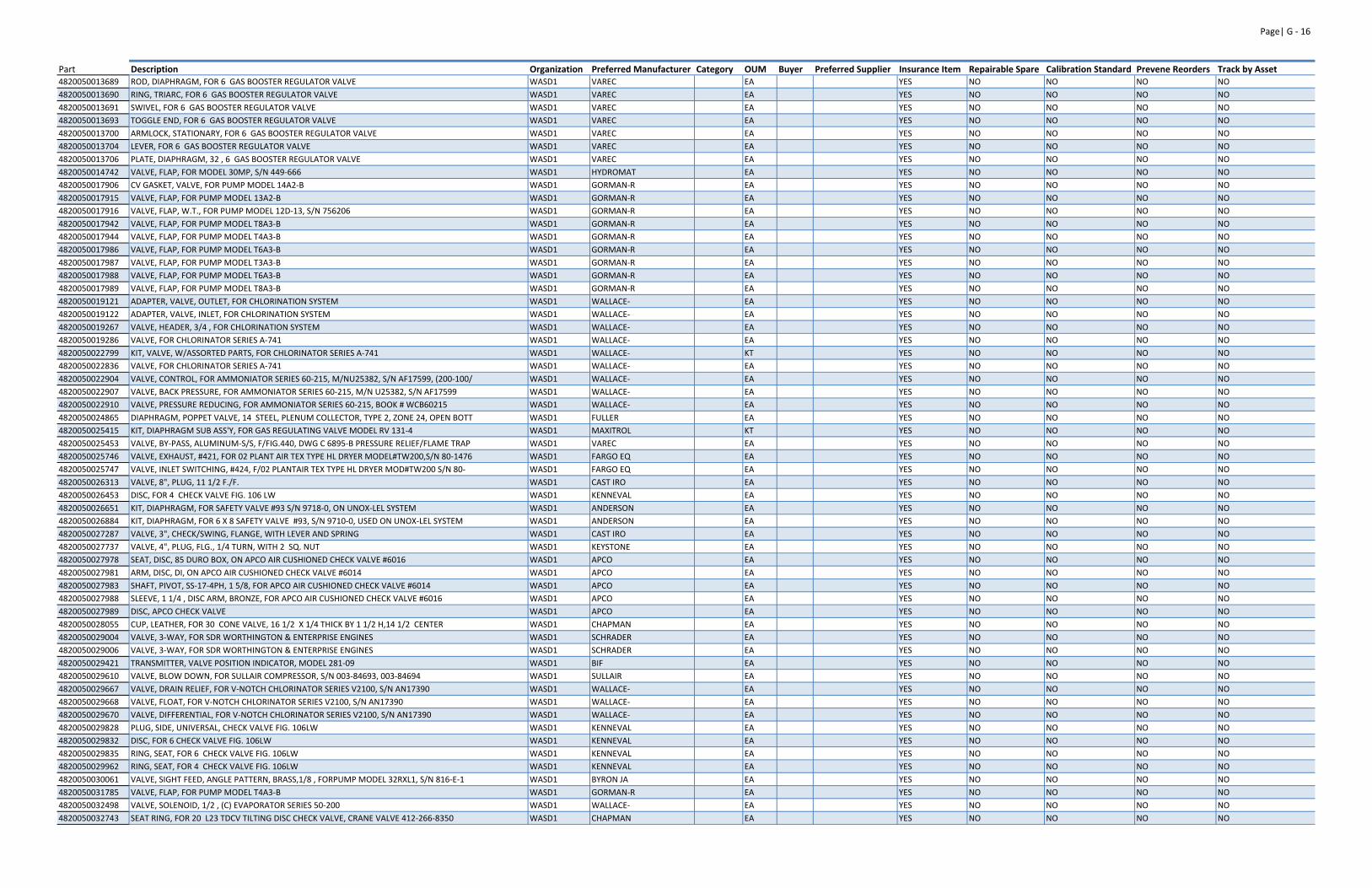
Page| G ‐ 16
Part Description Organization Preferred Manufacturer Category OUM Buyer Preferred Supplier Insurance Item Repairable Spare Calibration Standard Prevene Reorders Track by Asset4820050013689 ROD, DIAPHRAGM, FOR 6 GAS BOOSTER REGULATOR VALVE WASD1 VAREC EA YES NO NO NO NO
4820050013690 RING, TRIARC, FOR 6 GAS BOOSTER REGULATOR VALVE WASD1 VAREC EA YES NO NO NO NO
4820050013691 SWIVEL, FOR 6 GAS BOOSTER REGULATOR VALVE WASD1 VAREC EA YES NO NO NO NO
4820050013693 TOGGLE END, FOR 6 GAS BOOSTER REGULATOR VALVE WASD1 VAREC EA YES NO NO NO NO
4820050013700 ARMLOCK, STATIONARY, FOR 6 GAS BOOSTER REGULATOR VALVE WASD1 VAREC EA YES NO NO NO NO
4820050013704 LEVER, FOR 6 GAS BOOSTER REGULATOR VALVE WASD1 VAREC EA YES NO NO NO NO
4820050013706 PLATE, DIAPHRAGM, 32 , 6 GAS BOOSTER REGULATOR VALVE WASD1 VAREC EA YES NO NO NO NO
4820050014742 VALVE, FLAP, FOR MODEL 30MP, S/N 449‐666 WASD1 HYDROMAT EA YES NO NO NO NO
4820050017906 CV GASKET, VALVE, FOR PUMP MODEL 14A2‐B WASD1 GORMAN‐R EA YES NO NO NO NO
4820050017915 VALVE, FLAP, FOR PUMP MODEL 13A2‐B WASD1 GORMAN‐R EA YES NO NO NO NO
4820050017916 VALVE, FLAP, W.T., FOR PUMP MODEL 12D‐13, S/N 756206 WASD1 GORMAN‐R EA YES NO NO NO NO
4820050017942 VALVE, FLAP, FOR PUMP MODEL T8A3‐B WASD1 GORMAN‐R EA YES NO NO NO NO
4820050017944 VALVE, FLAP, FOR PUMP MODEL T4A3‐B WASD1 GORMAN‐R EA YES NO NO NO NO
4820050017986 VALVE, FLAP, FOR PUMP MODEL T6A3‐B WASD1 GORMAN‐R EA YES NO NO NO NO
4820050017987 VALVE, FLAP, FOR PUMP MODEL T3A3‐B WASD1 GORMAN‐R EA YES NO NO NO NO
4820050017988 VALVE, FLAP, FOR PUMP MODEL T6A3‐B WASD1 GORMAN‐R EA YES NO NO NO NO
4820050017989 VALVE, FLAP, FOR PUMP MODEL T8A3‐B WASD1 GORMAN‐R EA YES NO NO NO NO
4820050019121 ADAPTER, VALVE, OUTLET, FOR CHLORINATION SYSTEM WASD1 WALLACE‐ EA YES NO NO NO NO
4820050019122 ADAPTER, VALVE, INLET, FOR CHLORINATION SYSTEM WASD1 WALLACE‐ EA YES NO NO NO NO
4820050019267 VALVE, HEADER, 3/4 , FOR CHLORINATION SYSTEM WASD1 WALLACE‐ EA YES NO NO NO NO
4820050019286 VALVE, FOR CHLORINATOR SERIES A‐741 WASD1 WALLACE‐ EA YES NO NO NO NO
4820050022799 KIT, VALVE, W/ASSORTED PARTS, FOR CHLORINATOR SERIES A‐741 WASD1 WALLACE‐ KT YES NO NO NO NO
4820050022836 VALVE, FOR CHLORINATOR SERIES A‐741 WASD1 WALLACE‐ EA YES NO NO NO NO
4820050022904 VALVE, CONTROL, FOR AMMONIATOR SERIES 60‐215, M/NU25382, S/N AF17599, (200‐100/ WASD1 WALLACE‐ EA YES NO NO NO NO
4820050022907 VALVE, BACK PRESSURE, FOR AMMONIATOR SERIES 60‐215, M/N U25382, S/N AF17599 WASD1 WALLACE‐ EA YES NO NO NO NO
4820050022910 VALVE, PRESSURE REDUCING, FOR AMMONIATOR SERIES 60‐215, BOOK # WCB60215 WASD1 WALLACE‐ EA YES NO NO NO NO
4820050024865 DIAPHRAGM, POPPET VALVE, 14 STEEL, PLENUM COLLECTOR, TYPE 2, ZONE 24, OPEN BOTT WASD1 FULLER EA YES NO NO NO NO
4820050025415 KIT, DIAPHRAGM SUB ASS'Y, FOR GAS REGULATING VALVE MODEL RV 131‐4 WASD1 MAXITROL KT YES NO NO NO NO
4820050025453 VALVE, BY‐PASS, ALUMINUM‐S/S, F/FIG.440, DWG C 6895‐B PRESSURE RELIEF/FLAME TRAP WASD1 VAREC EA YES NO NO NO NO
4820050025746 VALVE, EXHAUST, #421, FOR 02 PLANT AIR TEX TYPE HL DRYER MODEL#TW200,S/N 80‐1476 WASD1 FARGO EQ EA YES NO NO NO NO
4820050025747 VALVE, INLET SWITCHING, #424, F/02 PLANTAIR TEX TYPE HL DRYER MOD#TW200 S/N 80‐ WASD1 FARGO EQ EA YES NO NO NO NO
4820050026313 VALVE, 8", PLUG, 11 1/2 F./F. WASD1 CAST IRO EA YES NO NO NO NO
4820050026453 DISC, FOR 4 CHECK VALVE FIG. 106 LW WASD1 KENNEVAL EA YES NO NO NO NO
4820050026651 KIT, DIAPHRAGM, FOR SAFETY VALVE #93 S/N 9718‐0, ON UNOX‐LEL SYSTEM WASD1 ANDERSON EA YES NO NO NO NO
4820050026884 KIT, DIAPHRAGM, FOR 6 X 8 SAFETY VALVE #93, S/N 9710‐0, USED ON UNOX‐LEL SYSTEM WASD1 ANDERSON EA YES NO NO NO NO
4820050027287 VALVE, 3", CHECK/SWING, FLANGE, WITH LEVER AND SPRING WASD1 CAST IRO EA YES NO NO NO NO
4820050027737 VALVE, 4", PLUG, FLG., 1/4 TURN, WITH 2 SQ. NUT WASD1 KEYSTONE EA YES NO NO NO NO
4820050027978 SEAT, DISC, 85 DURO BOX, ON APCO AIR CUSHIONED CHECK VALVE #6016 WASD1 APCO EA YES NO NO NO NO
4820050027981 ARM, DISC, DI, ON APCO AIR CUSHIONED CHECK VALVE #6014 WASD1 APCO EA YES NO NO NO NO
4820050027983 SHAFT, PIVOT, SS‐17‐4PH, 1 5/8, FOR APCO AIR CUSHIONED CHECK VALVE #6014 WASD1 APCO EA YES NO NO NO NO
4820050027988 SLEEVE, 1 1/4 , DISC ARM, BRONZE, FOR APCO AIR CUSHIONED CHECK VALVE #6016 WASD1 APCO EA YES NO NO NO NO
4820050027989 DISC, APCO CHECK VALVE WASD1 APCO EA YES NO NO NO NO
4820050028055 CUP, LEATHER, FOR 30 CONE VALVE, 16 1/2 X 1/4 THICK BY 1 1/2 H,14 1/2 CENTER WASD1 CHAPMAN EA YES NO NO NO NO
4820050029004 VALVE, 3‐WAY, FOR SDR WORTHINGTON & ENTERPRISE ENGINES WASD1 SCHRADER EA YES NO NO NO NO
4820050029006 VALVE, 3‐WAY, FOR SDR WORTHINGTON & ENTERPRISE ENGINES WASD1 SCHRADER EA YES NO NO NO NO
4820050029421 TRANSMITTER, VALVE POSITION INDICATOR, MODEL 281‐09 WASD1 BIF EA YES NO NO NO NO
4820050029610 VALVE, BLOW DOWN, FOR SULLAIR COMPRESSOR, S/N 003‐84693, 003‐84694 WASD1 SULLAIR EA YES NO NO NO NO
4820050029667 VALVE, DRAIN RELIEF, FOR V‐NOTCH CHLORINATOR SERIES V2100, S/N AN17390 WASD1 WALLACE‐ EA YES NO NO NO NO
4820050029668 VALVE, FLOAT, FOR V‐NOTCH CHLORINATOR SERIES V2100, S/N AN17390 WASD1 WALLACE‐ EA YES NO NO NO NO
4820050029670 VALVE, DIFFERENTIAL, FOR V‐NOTCH CHLORINATOR SERIES V2100, S/N AN17390 WASD1 WALLACE‐ EA YES NO NO NO NO
4820050029828 PLUG, SIDE, UNIVERSAL, CHECK VALVE FIG. 106LW WASD1 KENNEVAL EA YES NO NO NO NO
4820050029832 DISC, FOR 6 CHECK VALVE FIG. 106LW WASD1 KENNEVAL EA YES NO NO NO NO
4820050029835 RING, SEAT, FOR 6 CHECK VALVE FIG. 106LW WASD1 KENNEVAL EA YES NO NO NO NO
4820050029962 RING, SEAT, FOR 4 CHECK VALVE FIG. 106LW WASD1 KENNEVAL EA YES NO NO NO NO
4820050030061 VALVE, SIGHT FEED, ANGLE PATTERN, BRASS,1/8 , FORPUMP MODEL 32RXL1, S/N 816‐E‐1 WASD1 BYRON JA EA YES NO NO NO NO
4820050031785 VALVE, FLAP, FOR PUMP MODEL T4A3‐B WASD1 GORMAN‐R EA YES NO NO NO NO
4820050032498 VALVE, SOLENOID, 1/2 , (C) EVAPORATOR SERIES 50‐200 WASD1 WALLACE‐ EA YES NO NO NO NO
4820050032743 SEAT RING, FOR 20 L23 TDCV TILTING DISC CHECK VALVE, CRANE VALVE 412‐266‐8350 WASD1 CHAPMAN EA YES NO NO NO NO
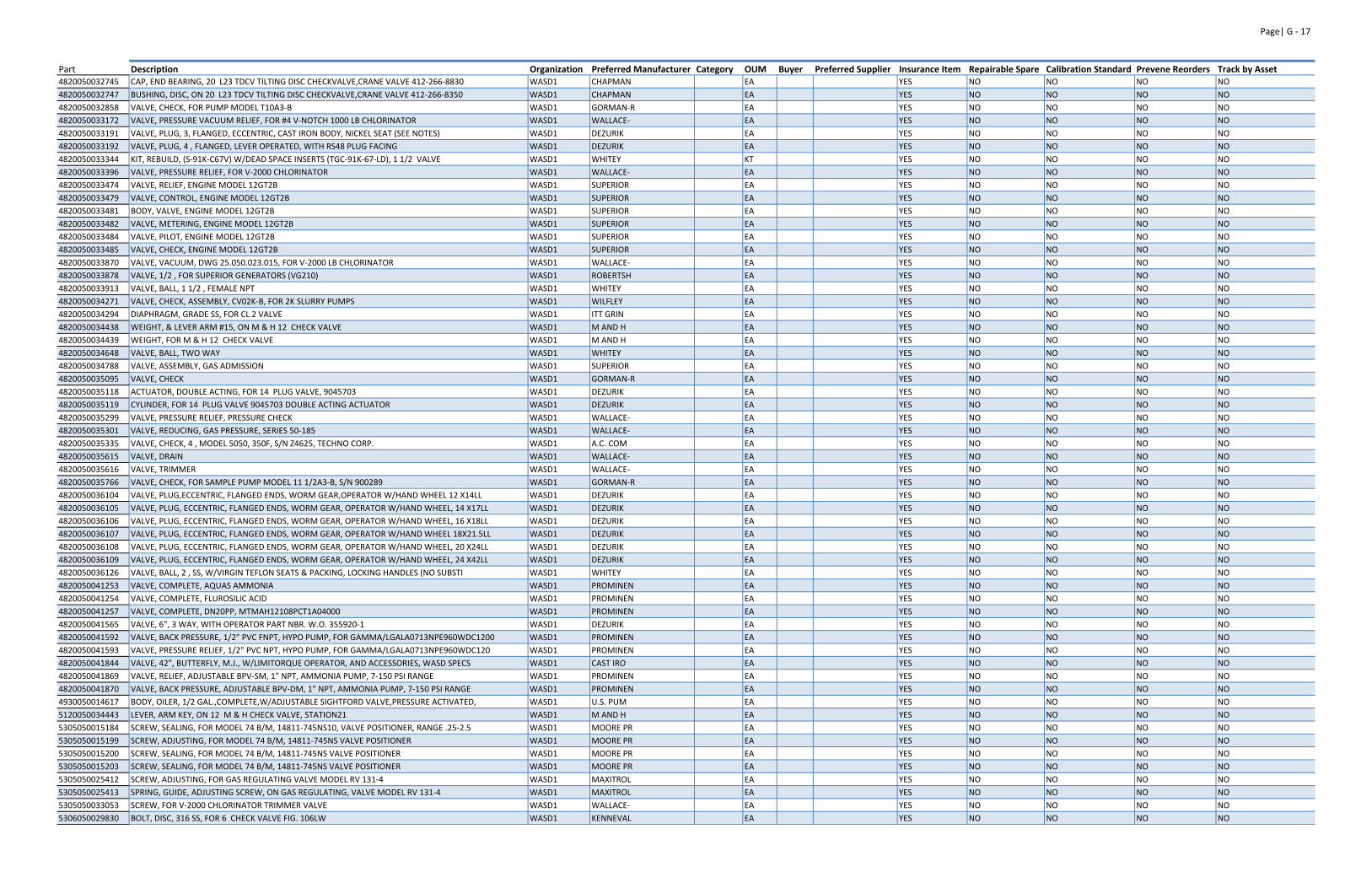
Page| G ‐ 17
Part Description Organization Preferred Manufacturer Category OUM Buyer Preferred Supplier Insurance Item Repairable Spare Calibration Standard Prevene Reorders Track by Asset4820050032745 CAP, END BEARING, 20 L23 TDCV TILTING DISC CHECKVALVE,CRANE VALVE 412‐266‐8830 WASD1 CHAPMAN EA YES NO NO NO NO
4820050032747 BUSHING, DISC, ON 20 L23 TDCV TILTING DISC CHECKVALVE,CRANE VALVE 412‐266‐8350 WASD1 CHAPMAN EA YES NO NO NO NO
4820050032858 VALVE, CHECK, FOR PUMP MODEL T10A3‐B WASD1 GORMAN‐R EA YES NO NO NO NO
4820050033172 VALVE, PRESSURE VACUUM RELIEF, FOR #4 V‐NOTCH 1000 LB CHLORINATOR WASD1 WALLACE‐ EA YES NO NO NO NO
4820050033191 VALVE, PLUG, 3, FLANGED, ECCENTRIC, CAST IRON BODY, NICKEL SEAT (SEE NOTES) WASD1 DEZURIK EA YES NO NO NO NO
4820050033192 VALVE, PLUG, 4 , FLANGED, LEVER OPERATED, WITH RS48 PLUG FACING WASD1 DEZURIK EA YES NO NO NO NO
4820050033344 KIT, REBUILD, (S‐91K‐C67V) W/DEAD SPACE INSERTS (TGC‐91K‐67‐LD), 1 1/2 VALVE WASD1 WHITEY KT YES NO NO NO NO
4820050033396 VALVE, PRESSURE RELIEF, FOR V‐2000 CHLORINATOR WASD1 WALLACE‐ EA YES NO NO NO NO
4820050033474 VALVE, RELIEF, ENGINE MODEL 12GT2B WASD1 SUPERIOR EA YES NO NO NO NO
4820050033479 VALVE, CONTROL, ENGINE MODEL 12GT2B WASD1 SUPERIOR EA YES NO NO NO NO
4820050033481 BODY, VALVE, ENGINE MODEL 12GT2B WASD1 SUPERIOR EA YES NO NO NO NO
4820050033482 VALVE, METERING, ENGINE MODEL 12GT2B WASD1 SUPERIOR EA YES NO NO NO NO
4820050033484 VALVE, PILOT, ENGINE MODEL 12GT2B WASD1 SUPERIOR EA YES NO NO NO NO
4820050033485 VALVE, CHECK, ENGINE MODEL 12GT2B WASD1 SUPERIOR EA YES NO NO NO NO
4820050033870 VALVE, VACUUM, DWG 25.050.023.015, FOR V‐2000 LB CHLORINATOR WASD1 WALLACE‐ EA YES NO NO NO NO
4820050033878 VALVE, 1/2 , FOR SUPERIOR GENERATORS (VG210) WASD1 ROBERTSH EA YES NO NO NO NO
4820050033913 VALVE, BALL, 1 1/2 , FEMALE NPT WASD1 WHITEY EA YES NO NO NO NO
4820050034271 VALVE, CHECK, ASSEMBLY, CV02K‐B, FOR 2K SLURRY PUMPS WASD1 WILFLEY EA YES NO NO NO NO
4820050034294 DIAPHRAGM, GRADE SS, FOR CL 2 VALVE WASD1 ITT GRIN EA YES NO NO NO NO
4820050034438 WEIGHT, & LEVER ARM #15, ON M & H 12 CHECK VALVE WASD1 M AND H EA YES NO NO NO NO
4820050034439 WEIGHT, FOR M & H 12 CHECK VALVE WASD1 M AND H EA YES NO NO NO NO
4820050034648 VALVE, BALL, TWO WAY WASD1 WHITEY EA YES NO NO NO NO
4820050034788 VALVE, ASSEMBLY, GAS ADMISSION WASD1 SUPERIOR EA YES NO NO NO NO
4820050035095 VALVE, CHECK WASD1 GORMAN‐R EA YES NO NO NO NO
4820050035118 ACTUATOR, DOUBLE ACTING, FOR 14 PLUG VALVE, 9045703 WASD1 DEZURIK EA YES NO NO NO NO
4820050035119 CYLINDER, FOR 14 PLUG VALVE 9045703 DOUBLE ACTING ACTUATOR WASD1 DEZURIK EA YES NO NO NO NO
4820050035299 VALVE, PRESSURE RELIEF, PRESSURE CHECK WASD1 WALLACE‐ EA YES NO NO NO NO
4820050035301 VALVE, REDUCING, GAS PRESSURE, SERIES 50‐185 WASD1 WALLACE‐ EA YES NO NO NO NO
4820050035335 VALVE, CHECK, 4 , MODEL 5050, 350F, S/N Z4625, TECHNO CORP. WASD1 A.C. COM EA YES NO NO NO NO
4820050035615 VALVE, DRAIN WASD1 WALLACE‐ EA YES NO NO NO NO
4820050035616 VALVE, TRIMMER WASD1 WALLACE‐ EA YES NO NO NO NO
4820050035766 VALVE, CHECK, FOR SAMPLE PUMP MODEL 11 1/2A3‐B, S/N 900289 WASD1 GORMAN‐R EA YES NO NO NO NO
4820050036104 VALVE, PLUG,ECCENTRIC, FLANGED ENDS, WORM GEAR,OPERATOR W/HAND WHEEL 12 X14LL WASD1 DEZURIK EA YES NO NO NO NO
4820050036105 VALVE, PLUG, ECCENTRIC, FLANGED ENDS, WORM GEAR, OPERATOR W/HAND WHEEL, 14 X17LL WASD1 DEZURIK EA YES NO NO NO NO
4820050036106 VALVE, PLUG, ECCENTRIC, FLANGED ENDS, WORM GEAR, OPERATOR W/HAND WHEEL, 16 X18LL WASD1 DEZURIK EA YES NO NO NO NO
4820050036107 VALVE, PLUG, ECCENTRIC, FLANGED ENDS, WORM GEAR, OPERATOR W/HAND WHEEL 18X21.5LL WASD1 DEZURIK EA YES NO NO NO NO
4820050036108 VALVE, PLUG, ECCENTRIC, FLANGED ENDS, WORM GEAR, OPERATOR W/HAND WHEEL, 20 X24LL WASD1 DEZURIK EA YES NO NO NO NO
4820050036109 VALVE, PLUG, ECCENTRIC, FLANGED ENDS, WORM GEAR, OPERATOR W/HAND WHEEL, 24 X42LL WASD1 DEZURIK EA YES NO NO NO NO
4820050036126 VALVE, BALL, 2 , SS, W/VIRGIN TEFLON SEATS & PACKING, LOCKING HANDLES (NO SUBSTI WASD1 WHITEY EA YES NO NO NO NO
4820050041253 VALVE, COMPLETE, AQUAS AMMONIA WASD1 PROMINEN EA YES NO NO NO NO
4820050041254 VALVE, COMPLETE, FLUROSILIC ACID WASD1 PROMINEN EA YES NO NO NO NO
4820050041257 VALVE, COMPLETE, DN20PP, MTMAH12108PCT1A04000 WASD1 PROMINEN EA YES NO NO NO NO
4820050041565 VALVE, 6", 3 WAY, WITH OPERATOR PART NBR. W.O. 355920‐1 WASD1 DEZURIK EA YES NO NO NO NO
4820050041592 VALVE, BACK PRESSURE, 1/2" PVC FNPT, HYPO PUMP, FOR GAMMA/LGALA0713NPE960WDC1200 WASD1 PROMINEN EA YES NO NO NO NO
4820050041593 VALVE, PRESSURE RELIEF, 1/2" PVC NPT, HYPO PUMP, FOR GAMMA/LGALA0713NPE960WDC120 WASD1 PROMINEN EA YES NO NO NO NO
4820050041844 VALVE, 42", BUTTERFLY, M.J., W/LIMITORQUE OPERATOR, AND ACCESSORIES, WASD SPECS WASD1 CAST IRO EA YES NO NO NO NO
4820050041869 VALVE, RELIEF, ADJUSTABLE BPV‐SM, 1" NPT, AMMONIA PUMP, 7‐150 PSI RANGE WASD1 PROMINEN EA YES NO NO NO NO
4820050041870 VALVE, BACK PRESSURE, ADJUSTABLE BPV‐DM, 1" NPT, AMMONIA PUMP, 7‐150 PSI RANGE WASD1 PROMINEN EA YES NO NO NO NO
4930050014617 BODY, OILER, 1/2 GAL.,COMPLETE,W/ADJUSTABLE SIGHTFORD VALVE,PRESSURE ACTIVATED, WASD1 U.S. PUM EA YES NO NO NO NO
5120050034443 LEVER, ARM KEY, ON 12 M & H CHECK VALVE, STATION21 WASD1 M AND H EA YES NO NO NO NO
5305050015184 SCREW, SEALING, FOR MODEL 74 B/M, 14811‐745NS10, VALVE POSITIONER, RANGE .25‐2.5 WASD1 MOORE PR EA YES NO NO NO NO
5305050015199 SCREW, ADJUSTING, FOR MODEL 74 B/M, 14811‐745NS VALVE POSITIONER WASD1 MOORE PR EA YES NO NO NO NO
5305050015200 SCREW, SEALING, FOR MODEL 74 B/M, 14811‐745NS VALVE POSITIONER WASD1 MOORE PR EA YES NO NO NO NO
5305050015203 SCREW, SEALING, FOR MODEL 74 B/M, 14811‐745NS VALVE POSITIONER WASD1 MOORE PR EA YES NO NO NO NO
5305050025412 SCREW, ADJUSTING, FOR GAS REGULATING VALVE MODEL RV 131‐4 WASD1 MAXITROL EA YES NO NO NO NO
5305050025413 SPRING, GUIDE, ADJUSTING SCREW, ON GAS REGULATING, VALVE MODEL RV 131‐4 WASD1 MAXITROL EA YES NO NO NO NO
5305050033053 SCREW, FOR V‐2000 CHLORINATOR TRIMMER VALVE WASD1 WALLACE‐ EA YES NO NO NO NO
5306050029830 BOLT, DISC, 316 SS, FOR 6 CHECK VALVE FIG. 106LW WASD1 KENNEVAL EA YES NO NO NO NO
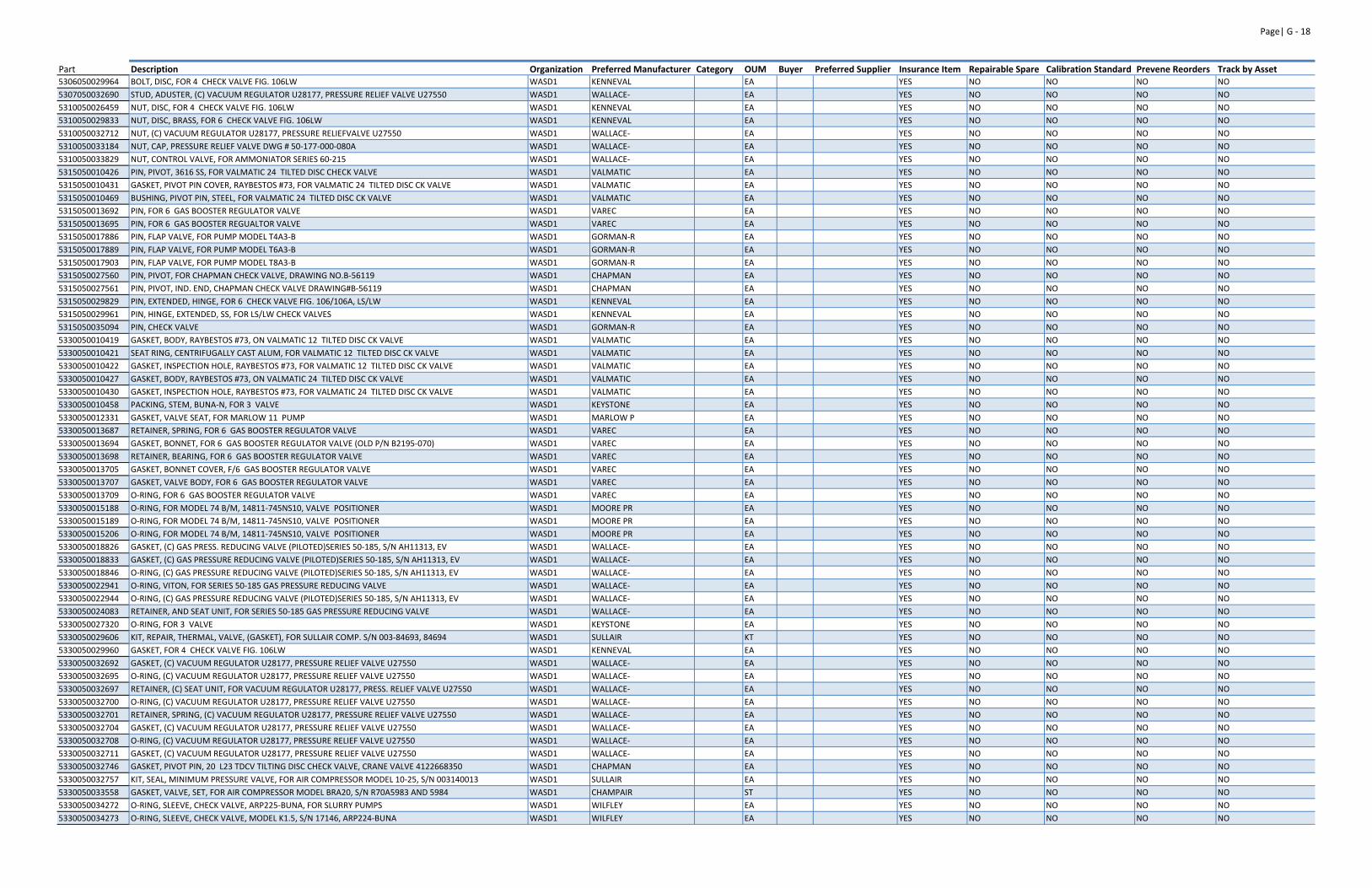
Page| G ‐ 18
Part Description Organization Preferred Manufacturer Category OUM Buyer Preferred Supplier Insurance Item Repairable Spare Calibration Standard Prevene Reorders Track by Asset5306050029964 BOLT, DISC, FOR 4 CHECK VALVE FIG. 106LW WASD1 KENNEVAL EA YES NO NO NO NO
5307050032690 STUD, ADUSTER, (C) VACUUM REGULATOR U28177, PRESSURE RELIEF VALVE U27550 WASD1 WALLACE‐ EA YES NO NO NO NO
5310050026459 NUT, DISC, FOR 4 CHECK VALVE FIG. 106LW WASD1 KENNEVAL EA YES NO NO NO NO
5310050029833 NUT, DISC, BRASS, FOR 6 CHECK VALVE FIG. 106LW WASD1 KENNEVAL EA YES NO NO NO NO
5310050032712 NUT, (C) VACUUM REGULATOR U28177, PRESSURE RELIEFVALVE U27550 WASD1 WALLACE‐ EA YES NO NO NO NO
5310050033184 NUT, CAP, PRESSURE RELIEF VALVE DWG # 50‐177‐000‐080A WASD1 WALLACE‐ EA YES NO NO NO NO
5310050033829 NUT, CONTROL VALVE, FOR AMMONIATOR SERIES 60‐215 WASD1 WALLACE‐ EA YES NO NO NO NO
5315050010426 PIN, PIVOT, 3616 SS, FOR VALMATIC 24 TILTED DISC CHECK VALVE WASD1 VALMATIC EA YES NO NO NO NO
5315050010431 GASKET, PIVOT PIN COVER, RAYBESTOS #73, FOR VALMATIC 24 TILTED DISC CK VALVE WASD1 VALMATIC EA YES NO NO NO NO
5315050010469 BUSHING, PIVOT PIN, STEEL, FOR VALMATIC 24 TILTED DISC CK VALVE WASD1 VALMATIC EA YES NO NO NO NO
5315050013692 PIN, FOR 6 GAS BOOSTER REGULATOR VALVE WASD1 VAREC EA YES NO NO NO NO
5315050013695 PIN, FOR 6 GAS BOOSTER REGUALTOR VALVE WASD1 VAREC EA YES NO NO NO NO
5315050017886 PIN, FLAP VALVE, FOR PUMP MODEL T4A3‐B WASD1 GORMAN‐R EA YES NO NO NO NO
5315050017889 PIN, FLAP VALVE, FOR PUMP MODEL T6A3‐B WASD1 GORMAN‐R EA YES NO NO NO NO
5315050017903 PIN, FLAP VALVE, FOR PUMP MODEL T8A3‐B WASD1 GORMAN‐R EA YES NO NO NO NO
5315050027560 PIN, PIVOT, FOR CHAPMAN CHECK VALVE, DRAWING NO.B‐56119 WASD1 CHAPMAN EA YES NO NO NO NO
5315050027561 PIN, PIVOT, IND. END, CHAPMAN CHECK VALVE DRAWING#B‐56119 WASD1 CHAPMAN EA YES NO NO NO NO
5315050029829 PIN, EXTENDED, HINGE, FOR 6 CHECK VALVE FIG. 106/106A, LS/LW WASD1 KENNEVAL EA YES NO NO NO NO
5315050029961 PIN, HINGE, EXTENDED, SS, FOR LS/LW CHECK VALVES WASD1 KENNEVAL EA YES NO NO NO NO
5315050035094 PIN, CHECK VALVE WASD1 GORMAN‐R EA YES NO NO NO NO
5330050010419 GASKET, BODY, RAYBESTOS #73, ON VALMATIC 12 TILTED DISC CK VALVE WASD1 VALMATIC EA YES NO NO NO NO
5330050010421 SEAT RING, CENTRIFUGALLY CAST ALUM, FOR VALMATIC 12 TILTED DISC CK VALVE WASD1 VALMATIC EA YES NO NO NO NO
5330050010422 GASKET, INSPECTION HOLE, RAYBESTOS #73, FOR VALMATIC 12 TILTED DISC CK VALVE WASD1 VALMATIC EA YES NO NO NO NO
5330050010427 GASKET, BODY, RAYBESTOS #73, ON VALMATIC 24 TILTED DISC CK VALVE WASD1 VALMATIC EA YES NO NO NO NO
5330050010430 GASKET, INSPECTION HOLE, RAYBESTOS #73, FOR VALMATIC 24 TILTED DISC CK VALVE WASD1 VALMATIC EA YES NO NO NO NO
5330050010458 PACKING, STEM, BUNA‐N, FOR 3 VALVE WASD1 KEYSTONE EA YES NO NO NO NO
5330050012331 GASKET, VALVE SEAT, FOR MARLOW 11 PUMP WASD1 MARLOW P EA YES NO NO NO NO
5330050013687 RETAINER, SPRING, FOR 6 GAS BOOSTER REGULATOR VALVE WASD1 VAREC EA YES NO NO NO NO
5330050013694 GASKET, BONNET, FOR 6 GAS BOOSTER REGULATOR VALVE (OLD P/N B2195‐070) WASD1 VAREC EA YES NO NO NO NO
5330050013698 RETAINER, BEARING, FOR 6 GAS BOOSTER REGULATOR VALVE WASD1 VAREC EA YES NO NO NO NO
5330050013705 GASKET, BONNET COVER, F/6 GAS BOOSTER REGULATOR VALVE WASD1 VAREC EA YES NO NO NO NO
5330050013707 GASKET, VALVE BODY, FOR 6 GAS BOOSTER REGULATOR VALVE WASD1 VAREC EA YES NO NO NO NO
5330050013709 O‐RING, FOR 6 GAS BOOSTER REGULATOR VALVE WASD1 VAREC EA YES NO NO NO NO
5330050015188 O‐RING, FOR MODEL 74 B/M, 14811‐745NS10, VALVE POSITIONER WASD1 MOORE PR EA YES NO NO NO NO
5330050015189 O‐RING, FOR MODEL 74 B/M, 14811‐745NS10, VALVE POSITIONER WASD1 MOORE PR EA YES NO NO NO NO
5330050015206 O‐RING, FOR MODEL 74 B/M, 14811‐745NS10, VALVE POSITIONER WASD1 MOORE PR EA YES NO NO NO NO
5330050018826 GASKET, (C) GAS PRESS. REDUCING VALVE (PILOTED)SERIES 50‐185, S/N AH11313, EV WASD1 WALLACE‐ EA YES NO NO NO NO
5330050018833 GASKET, (C) GAS PRESSURE REDUCING VALVE (PILOTED)SERIES 50‐185, S/N AH11313, EV WASD1 WALLACE‐ EA YES NO NO NO NO
5330050018846 O‐RING, (C) GAS PRESSURE REDUCING VALVE (PILOTED)SERIES 50‐185, S/N AH11313, EV WASD1 WALLACE‐ EA YES NO NO NO NO
5330050022941 O‐RING, VITON, FOR SERIES 50‐185 GAS PRESSURE REDUCING VALVE WASD1 WALLACE‐ EA YES NO NO NO NO
5330050022944 O‐RING, (C) GAS PRESSURE REDUCING VALVE (PILOTED)SERIES 50‐185, S/N AH11313, EV WASD1 WALLACE‐ EA YES NO NO NO NO
5330050024083 RETAINER, AND SEAT UNIT, FOR SERIES 50‐185 GAS PRESSURE REDUCING VALVE WASD1 WALLACE‐ EA YES NO NO NO NO
5330050027320 O‐RING, FOR 3 VALVE WASD1 KEYSTONE EA YES NO NO NO NO
5330050029606 KIT, REPAIR, THERMAL, VALVE, (GASKET), FOR SULLAIR COMP. S/N 003‐84693, 84694 WASD1 SULLAIR KT YES NO NO NO NO
5330050029960 GASKET, FOR 4 CHECK VALVE FIG. 106LW WASD1 KENNEVAL EA YES NO NO NO NO
5330050032692 GASKET, (C) VACUUM REGULATOR U28177, PRESSURE RELIEF VALVE U27550 WASD1 WALLACE‐ EA YES NO NO NO NO
5330050032695 O‐RING, (C) VACUUM REGULATOR U28177, PRESSURE RELIEF VALVE U27550 WASD1 WALLACE‐ EA YES NO NO NO NO
5330050032697 RETAINER, (C) SEAT UNIT, FOR VACUUM REGULATOR U28177, PRESS. RELIEF VALVE U27550 WASD1 WALLACE‐ EA YES NO NO NO NO
5330050032700 O‐RING, (C) VACUUM REGULATOR U28177, PRESSURE RELIEF VALVE U27550 WASD1 WALLACE‐ EA YES NO NO NO NO
5330050032701 RETAINER, SPRING, (C) VACUUM REGULATOR U28177, PRESSURE RELIEF VALVE U27550 WASD1 WALLACE‐ EA YES NO NO NO NO
5330050032704 GASKET, (C) VACUUM REGULATOR U28177, PRESSURE RELIEF VALVE U27550 WASD1 WALLACE‐ EA YES NO NO NO NO
5330050032708 O‐RING, (C) VACUUM REGULATOR U28177, PRESSURE RELIEF VALVE U27550 WASD1 WALLACE‐ EA YES NO NO NO NO
5330050032711 GASKET, (C) VACUUM REGULATOR U28177, PRESSURE RELIEF VALVE U27550 WASD1 WALLACE‐ EA YES NO NO NO NO
5330050032746 GASKET, PIVOT PIN, 20 L23 TDCV TILTING DISC CHECK VALVE, CRANE VALVE 4122668350 WASD1 CHAPMAN EA YES NO NO NO NO
5330050032757 KIT, SEAL, MINIMUM PRESSURE VALVE, FOR AIR COMPRESSOR MODEL 10‐25, S/N 003140013 WASD1 SULLAIR EA YES NO NO NO NO
5330050033558 GASKET, VALVE, SET, FOR AIR COMPRESSOR MODEL BRA20, S/N R70A5983 AND 5984 WASD1 CHAMPAIR ST YES NO NO NO NO
5330050034272 O‐RING, SLEEVE, CHECK VALVE, ARP225‐BUNA, FOR SLURRY PUMPS WASD1 WILFLEY EA YES NO NO NO NO
5330050034273 O‐RING, SLEEVE, CHECK VALVE, MODEL K1.5, S/N 17146, ARP224‐BUNA WASD1 WILFLEY EA YES NO NO NO NO
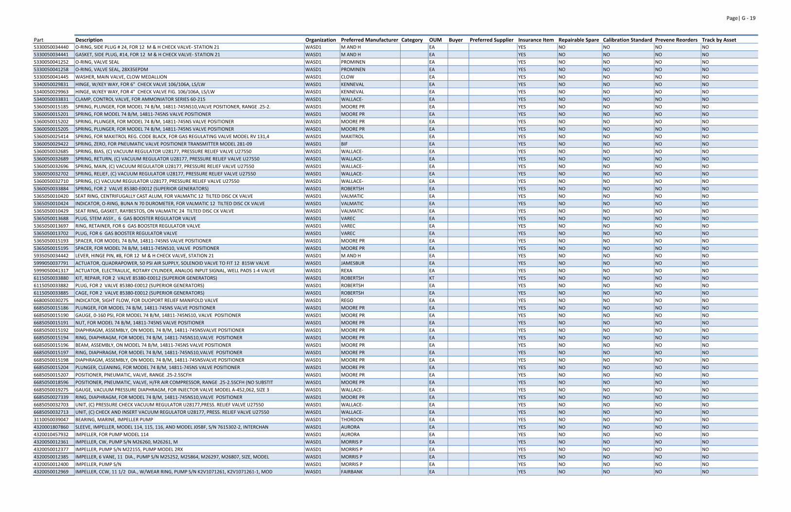
Page| G ‐ 19
Part Description Organization Preferred Manufacturer Category OUM Buyer Preferred Supplier Insurance Item Repairable Spare Calibration Standard Prevene Reorders Track by Asset5330050034440 O‐RING, SIDE PLUG # 24, FOR 12 M & H CHECK VALVE‐ STATION 21 WASD1 M AND H EA YES NO NO NO NO
5330050034441 GASKET, SIDE PLUG, #14, FOR 12 M & H CHECK VALVE‐ STATION 21 WASD1 M AND H EA YES NO NO NO NO
5330050041252 O‐RING, VALVE SEAL WASD1 PROMINEN EA YES NO NO NO NO
5330050041258 O‐RING, VALVE SEAL, 28X35EPDM WASD1 PROMINEN EA YES NO NO NO NO
5330050041445 WASHER, MAIN VALVE, CLOW MEDALLION WASD1 CLOW EA YES NO NO NO NO
5340050029831 HINGE, W/KEY WAY, FOR 6" CHECK VALVE 106/106A, LS/LW WASD1 KENNEVAL EA YES NO NO NO NO
5340050029963 HINGE, W/KEY WAY, FOR 4" CHECK VALVE FIG. 106/106A, LS/LW WASD1 KENNEVAL EA YES NO NO NO NO
5340050033831 CLAMP, CONTROL VALVE, FOR AMMONIATOR SERIES 60‐215 WASD1 WALLACE‐ EA YES NO NO NO NO
5360050015185 SPRING, PLUNGER, FOR MODEL 74 B/M, 14811‐745NS10,VALVE POSITIONER, RANGE .25‐2. WASD1 MOORE PR EA YES NO NO NO NO
5360050015201 SPRING, FOR MODEL 74 B/M, 14811‐745NS VALVE POSITIONER WASD1 MOORE PR EA YES NO NO NO NO
5360050015202 SPRING, PLUNGER, FOR MODEL 74 B/M, 14811‐745NS VALVE POSITIONER WASD1 MOORE PR EA YES NO NO NO NO
5360050015205 SPRING, PLUNGER, FOR MODEL 74 B/M, 14811‐745NS VALVE POSITIONER WASD1 MOORE PR EA YES NO NO NO NO
5360050025414 SPRING, FOR MAXITROL REG. CODE BLACK, FOR GAS REGULATING VALVE MODEL RV 131,4 WASD1 MAXITROL EA YES NO NO NO NO
5360050029422 SPRING, ZERO, FOR PNEUMATIC VALVE POSITIONER TRANSMITTER MODEL 281‐09 WASD1 BIF EA YES NO NO NO NO
5360050032685 SPRING, BIAS, (C) VACUUM REGULATOR U28177, PRESSURE RELIEF VALVE U27550 WASD1 WALLACE‐ EA YES NO NO NO NO
5360050032689 SPRING, RETURN, (C) VACUUM REGULATOR U28177, PRESSURE RELIEF VALVE U27550 WASD1 WALLACE‐ EA YES NO NO NO NO
5360050032696 SPRING, MAIN, (C) VACUUM REGULATOR U28177, PRESSURE RELIEF VALVE U27550 WASD1 WALLACE‐ EA YES NO NO NO NO
5360050032702 SPRING, RELIEF, (C) VACUUM REGULATOR U28177, PRESSURE RELIEF VALVE U27550 WASD1 WALLACE‐ EA YES NO NO NO NO
5360050032710 SPRING, (C) VACUUM REGULATOR U28177, PRESSURE RELIEF VALVE U27550 WASD1 WALLACE‐ EA YES NO NO NO NO
5360050033884 SPRING, FOR 2 VALVE 85380‐E0012 (SUPERIOR GENERATORS) WASD1 ROBERTSH EA YES NO NO NO NO
5365050010420 SEAT RING, CENTRIFUGALLY CAST ALUM, FOR VALMATIC 12 TILTED DISC CK VALVE WASD1 VALMATIC EA YES NO NO NO NO
5365050010424 INDICATOR, O‐RING, BUNA N 70 DUROMETER, FOR VALMATIC 12 TILTED DISC CK VALVE WASD1 VALMATIC EA YES NO NO NO NO
5365050010429 SEAT RING, GASKET, RAYBESTOS, ON VALMATIC 24 TILTED DISC CK VALVE WASD1 VALMATIC EA YES NO NO NO NO
5365050013688 PLUG, STEM ASSY., 6 GAS BOOSTER REGULATOR VALVE WASD1 VAREC EA YES NO NO NO NO
5365050013697 RING, RETAINER, FOR 6 GAS BOOSTER REGULATOR VALVE WASD1 VAREC EA YES NO NO NO NO
5365050013702 PLUG, FOR 6 GAS BOOSTER REGULATOR VALVE WASD1 VAREC EA YES NO NO NO NO
5365050015193 SPACER, FOR MODEL 74 B/M, 14811‐745NS VALVE POSITIONER WASD1 MOORE PR EA YES NO NO NO NO
5365050015195 SPACER, FOR MODEL 74 B/M, 14811‐745NS10, VALVE POSITIONER WASD1 MOORE PR EA YES NO NO NO NO
5935050034442 LEVER, HINGE PIN, #8, FOR 12 M & H CHECK VALVE, STATION 21 WASD1 M AND H EA YES NO NO NO NO
5999050037791 ACTUATOR, QUADRAPOWER, 50 PSI AIR SUPPLY, SOLENOID VALVE TO FIT 12 815W VALVE WASD1 JAMESBUR EA YES NO NO NO NO
5999050041317 ACTUATOR, ELECTRAULIC, ROTARY CYLINDER, ANALOG INPUT SIGNAL, WELL PADS 1‐4 VALVE WASD1 REXA EA YES NO NO NO NO
6115050033880 KIT, REPAIR, FOR 2 VALVE 85380‐E0012 (SUPERIOR GENERATORS) WASD1 ROBERTSH KT YES NO NO NO NO
6115050033882 PLUG, FOR 2 VALVE 85380‐E0012 (SUPERIOR GENERATORS) WASD1 ROBERTSH EA YES NO NO NO NO
6115050033885 CAGE, FOR 2 VALVE 85380‐E0012 (SUPERIOR GENERATORS) WASD1 ROBERTSH EA YES NO NO NO NO
6680050030275 INDICATOR, SIGHT FLOW, FOR DUOPORT RELIEF MANIFOLD VALVE WASD1 REGO EA YES NO NO NO NO
6685050015186 PLUNGER, FOR MODEL 74 B/M, 14811‐745NS VALVE POSITIONER WASD1 MOORE PR EA YES NO NO NO NO
6685050015190 GAUGE, 0‐160 PSI, FOR MODEL 74 B/M, 14811‐745NS10, VALVE POSITIONER WASD1 MOORE PR EA YES NO NO NO NO
6685050015191 NUT, FOR MODEL 74 B/M, 14811‐745NS VALVE POSITIONER WASD1 MOORE PR EA YES NO NO NO NO
6685050015192 DIAPHRAGM, ASSEMBLY, ON MODEL 74 B/M, 14811‐745NSVALVE POSITIONER WASD1 MOORE PR EA YES NO NO NO NO
6685050015194 RING, DIAPHRAGM, FOR MODEL 74 B/M, 14811‐745NS10,VALVE POSITIONER WASD1 MOORE PR EA YES NO NO NO NO
6685050015196 BEAM, ASSEMBLY, ON MODEL 74 B/M, 14811‐745NS VALVE POSITIONER WASD1 MOORE PR EA YES NO NO NO NO
6685050015197 RING, DIAPHRAGM, FOR MODEL 74 B/M, 14811‐745NS10,VALVE POSITIONER WASD1 MOORE PR EA YES NO NO NO NO
6685050015198 DIAPHRAGM, ASSEMBLY, ON MODEL 74 B/M, 14811‐745NSVALVE POSITIONER WASD1 MOORE PR EA YES NO NO NO NO
6685050015204 PLUNGER, CLEANING, FOR MODEL 74 B/M, 14811‐745NS VALVE POSITIONER WASD1 MOORE PR EA YES NO NO NO NO
6685050015207 POSITIONER, PNEUMATIC, VALVE, RANGE .25‐2.5SCFH WASD1 MOORE PR EA YES NO NO NO NO
6685050018596 POSITIONER, PNEUMATIC, VALVE, H/FR AIR COMPRESSOR, RANGE .25‐2.5SCFH (NO SUBSTIT WASD1 MOORE PR EA YES NO NO NO NO
6685050019275 GAUGE, VACUUM PRESSURE DIAPHRAGM, FOR INJECTOR VALVE MODEL A‐452,062, SIZE 3 WASD1 WALLACE‐ EA YES NO NO NO NO
6685050027339 RING, DIAPHRAGM, FOR MODEL 74 B/M, 14811‐745NS10,VALVE POSITIONER WASD1 MOORE PR EA YES NO NO NO NO
6685050032703 UNIT, (C) PRESSURE CHECK VACUUM REGULATOR U28177,PRESS. RELIEF VALVE U27550 WASD1 WALLACE‐ EA YES NO NO NO NO
6685050032713 UNIT, (C) CHECK AND INSERT VACUUM REGULATOR U28177, PRESS. RELIEF VALVE U27550 WASD1 WALLACE‐ EA YES NO NO NO NO
3110050039047 BEARING, MARINE, IMPELLER PUMP WASD1 THORDON EA YES NO NO NO NO
4320001807860 SLEEVE, IMPELLER, MODEL 114, 115, 116, AND MODEL J05BF, S/N 7615302‐2, INTERCHAN WASD1 AURORA EA YES NO NO NO NO
4320010457932 IMPELLER, FOR PUMP MODEL 114 WASD1 AURORA EA YES NO NO NO NO
4320050012361 IMPELLER, CW, PUMP S/N M26260, M26261, M WASD1 MORRIS P EA YES NO NO NO NO
4320050012377 IMPELLER, PUMP S/N M22155, PUMP MODEL 2RX WASD1 MORRIS P EA YES NO NO NO NO
4320050012385 IMPELLER, 6 VANE, 11 DIA., PUMP S/N M25252, M25864, M26297, M26807, SIZE, MODEL WASD1 MORRIS P EA YES NO NO NO NO
4320050012400 IMPELLER, PUMP S/N WASD1 MORRIS P EA YES NO NO NO NO
4320050012969 IMPELLER, CCW, 11 1/2 DIA., W/WEAR RING, PUMP S/N K2V1071261, K2V1071261‐1, MOD WASD1 FAIRBANK EA YES NO NO NO NO
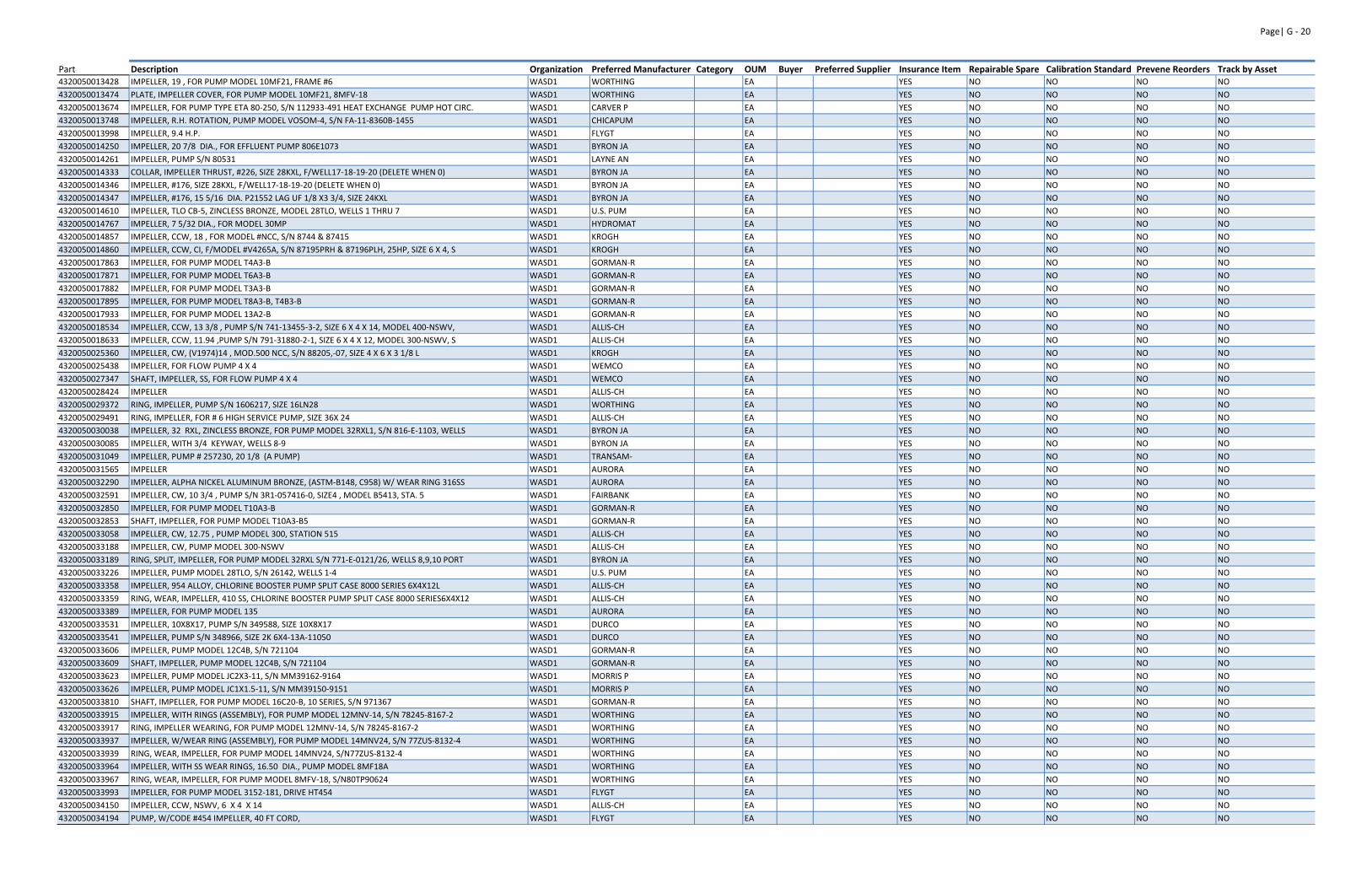
Page| G ‐ 20
Part Description Organization Preferred Manufacturer Category OUM Buyer Preferred Supplier Insurance Item Repairable Spare Calibration Standard Prevene Reorders Track by Asset4320050013428 IMPELLER, 19 , FOR PUMP MODEL 10MF21, FRAME #6 WASD1 WORTHING EA YES NO NO NO NO
4320050013474 PLATE, IMPELLER COVER, FOR PUMP MODEL 10MF21, 8MFV‐18 WASD1 WORTHING EA YES NO NO NO NO
4320050013674 IMPELLER, FOR PUMP TYPE ETA 80‐250, S/N 112933‐491 HEAT EXCHANGE PUMP HOT CIRC. WASD1 CARVER P EA YES NO NO NO NO
4320050013748 IMPELLER, R.H. ROTATION, PUMP MODEL VOSOM‐4, S/N FA‐11‐8360B‐1455 WASD1 CHICAPUM EA YES NO NO NO NO
4320050013998 IMPELLER, 9.4 H.P. WASD1 FLYGT EA YES NO NO NO NO
4320050014250 IMPELLER, 20 7/8 DIA., FOR EFFLUENT PUMP 806E1073 WASD1 BYRON JA EA YES NO NO NO NO
4320050014261 IMPELLER, PUMP S/N 80531 WASD1 LAYNE AN EA YES NO NO NO NO
4320050014333 COLLAR, IMPELLER THRUST, #226, SIZE 28KXL, F/WELL17‐18‐19‐20 (DELETE WHEN 0) WASD1 BYRON JA EA YES NO NO NO NO
4320050014346 IMPELLER, #176, SIZE 28KXL, F/WELL17‐18‐19‐20 (DELETE WHEN 0) WASD1 BYRON JA EA YES NO NO NO NO
4320050014347 IMPELLER, #176, 15 5/16 DIA. P21552 LAG UF 1/8 X3 3/4, SIZE 24KXL WASD1 BYRON JA EA YES NO NO NO NO
4320050014610 IMPELLER, TLO CB‐5, ZINCLESS BRONZE, MODEL 28TLO, WELLS 1 THRU 7 WASD1 U.S. PUM EA YES NO NO NO NO
4320050014767 IMPELLER, 7 5/32 DIA., FOR MODEL 30MP WASD1 HYDROMAT EA YES NO NO NO NO
4320050014857 IMPELLER, CCW, 18 , FOR MODEL #NCC, S/N 8744 & 87415 WASD1 KROGH EA YES NO NO NO NO
4320050014860 IMPELLER, CCW, CI, F/MODEL #V4265A, S/N 87195PRH & 87196PLH, 25HP, SIZE 6 X 4, S WASD1 KROGH EA YES NO NO NO NO
4320050017863 IMPELLER, FOR PUMP MODEL T4A3‐B WASD1 GORMAN‐R EA YES NO NO NO NO
4320050017871 IMPELLER, FOR PUMP MODEL T6A3‐B WASD1 GORMAN‐R EA YES NO NO NO NO
4320050017882 IMPELLER, FOR PUMP MODEL T3A3‐B WASD1 GORMAN‐R EA YES NO NO NO NO
4320050017895 IMPELLER, FOR PUMP MODEL T8A3‐B, T4B3‐B WASD1 GORMAN‐R EA YES NO NO NO NO
4320050017933 IMPELLER, FOR PUMP MODEL 13A2‐B WASD1 GORMAN‐R EA YES NO NO NO NO
4320050018534 IMPELLER, CCW, 13 3/8 , PUMP S/N 741‐13455‐3‐2, SIZE 6 X 4 X 14, MODEL 400‐NSWV, WASD1 ALLIS‐CH EA YES NO NO NO NO
4320050018633 IMPELLER, CCW, 11.94 ,PUMP S/N 791‐31880‐2‐1, SIZE 6 X 4 X 12, MODEL 300‐NSWV, S WASD1 ALLIS‐CH EA YES NO NO NO NO
4320050025360 IMPELLER, CW, (V1974)14 , MOD.500 NCC, S/N 88205,‐07, SIZE 4 X 6 X 3 1/8 L WASD1 KROGH EA YES NO NO NO NO
4320050025438 IMPELLER, FOR FLOW PUMP 4 X 4 WASD1 WEMCO EA YES NO NO NO NO
4320050027347 SHAFT, IMPELLER, SS, FOR FLOW PUMP 4 X 4 WASD1 WEMCO EA YES NO NO NO NO
4320050028424 IMPELLER WASD1 ALLIS‐CH EA YES NO NO NO NO
4320050029372 RING, IMPELLER, PUMP S/N 1606217, SIZE 16LN28 WASD1 WORTHING EA YES NO NO NO NO
4320050029491 RING, IMPELLER, FOR # 6 HIGH SERVICE PUMP, SIZE 36X 24 WASD1 ALLIS‐CH EA YES NO NO NO NO
4320050030038 IMPELLER, 32 RXL, ZINCLESS BRONZE, FOR PUMP MODEL 32RXL1, S/N 816‐E‐1103, WELLS WASD1 BYRON JA EA YES NO NO NO NO
4320050030085 IMPELLER, WITH 3/4 KEYWAY, WELLS 8‐9 WASD1 BYRON JA EA YES NO NO NO NO
4320050031049 IMPELLER, PUMP # 257230, 20 1/8 (A PUMP) WASD1 TRANSAM‐ EA YES NO NO NO NO
4320050031565 IMPELLER WASD1 AURORA EA YES NO NO NO NO
4320050032290 IMPELLER, ALPHA NICKEL ALUMINUM BRONZE, (ASTM‐B148, C958) W/ WEAR RING 316SS WASD1 AURORA EA YES NO NO NO NO
4320050032591 IMPELLER, CW, 10 3/4 , PUMP S/N 3R1‐057416‐0, SIZE4 , MODEL B5413, STA. 5 WASD1 FAIRBANK EA YES NO NO NO NO
4320050032850 IMPELLER, FOR PUMP MODEL T10A3‐B WASD1 GORMAN‐R EA YES NO NO NO NO
4320050032853 SHAFT, IMPELLER, FOR PUMP MODEL T10A3‐B5 WASD1 GORMAN‐R EA YES NO NO NO NO
4320050033058 IMPELLER, CW, 12.75 , PUMP MODEL 300, STATION 515 WASD1 ALLIS‐CH EA YES NO NO NO NO
4320050033188 IMPELLER, CW, PUMP MODEL 300‐NSWV WASD1 ALLIS‐CH EA YES NO NO NO NO
4320050033189 RING, SPLIT, IMPELLER, FOR PUMP MODEL 32RXL S/N 771‐E‐0121/26, WELLS 8,9,10 PORT WASD1 BYRON JA EA YES NO NO NO NO
4320050033226 IMPELLER, PUMP MODEL 28TLO, S/N 26142, WELLS 1‐4 WASD1 U.S. PUM EA YES NO NO NO NO
4320050033358 IMPELLER, 954 ALLOY, CHLORINE BOOSTER PUMP SPLIT CASE 8000 SERIES 6X4X12L WASD1 ALLIS‐CH EA YES NO NO NO NO
4320050033359 RING, WEAR, IMPELLER, 410 SS, CHLORINE BOOSTER PUMP SPLIT CASE 8000 SERIES6X4X12 WASD1 ALLIS‐CH EA YES NO NO NO NO
4320050033389 IMPELLER, FOR PUMP MODEL 135 WASD1 AURORA EA YES NO NO NO NO
4320050033531 IMPELLER, 10X8X17, PUMP S/N 349588, SIZE 10X8X17 WASD1 DURCO EA YES NO NO NO NO
4320050033541 IMPELLER, PUMP S/N 348966, SIZE 2K 6X4‐13A‐11050 WASD1 DURCO EA YES NO NO NO NO
4320050033606 IMPELLER, PUMP MODEL 12C4B, S/N 721104 WASD1 GORMAN‐R EA YES NO NO NO NO
4320050033609 SHAFT, IMPELLER, PUMP MODEL 12C4B, S/N 721104 WASD1 GORMAN‐R EA YES NO NO NO NO
4320050033623 IMPELLER, PUMP MODEL JC2X3‐11, S/N MM39162‐9164 WASD1 MORRIS P EA YES NO NO NO NO
4320050033626 IMPELLER, PUMP MODEL JC1X1.5‐11, S/N MM39150‐9151 WASD1 MORRIS P EA YES NO NO NO NO
4320050033810 SHAFT, IMPELLER, FOR PUMP MODEL 16C20‐B, 10 SERIES, S/N 971367 WASD1 GORMAN‐R EA YES NO NO NO NO
4320050033915 IMPELLER, WITH RINGS (ASSEMBLY), FOR PUMP MODEL 12MNV‐14, S/N 78245‐8167‐2 WASD1 WORTHING EA YES NO NO NO NO
4320050033917 RING, IMPELLER WEARING, FOR PUMP MODEL 12MNV‐14, S/N 78245‐8167‐2 WASD1 WORTHING EA YES NO NO NO NO
4320050033937 IMPELLER, W/WEAR RING (ASSEMBLY), FOR PUMP MODEL 14MNV24, S/N 77ZUS‐8132‐4 WASD1 WORTHING EA YES NO NO NO NO
4320050033939 RING, WEAR, IMPELLER, FOR PUMP MODEL 14MNV24, S/N77ZUS‐8132‐4 WASD1 WORTHING EA YES NO NO NO NO
4320050033964 IMPELLER, WITH SS WEAR RINGS, 16.50 DIA., PUMP MODEL 8MF18A WASD1 WORTHING EA YES NO NO NO NO
4320050033967 RING, WEAR, IMPELLER, FOR PUMP MODEL 8MFV‐18, S/N80TP90624 WASD1 WORTHING EA YES NO NO NO NO
4320050033993 IMPELLER, FOR PUMP MODEL 3152‐181, DRIVE HT454 WASD1 FLYGT EA YES NO NO NO NO
4320050034150 IMPELLER, CCW, NSWV, 6 X 4 X 14 WASD1 ALLIS‐CH EA YES NO NO NO NO
4320050034194 PUMP, W/CODE #454 IMPELLER, 40 FT CORD, WASD1 FLYGT EA YES NO NO NO NO
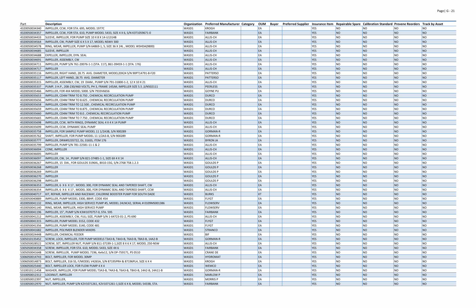
Page| G ‐ 21
Part Description Organization Preferred Manufacturer Category OUM Buyer Preferred Supplier Insurance Item Repairable Spare Calibration Standard Prevene Reorders Track by Asset4320050034340 IMPELLER, CCW, FOR STA. 695, MODEL 1977C WASD1 KROGH EA YES NO NO NO NO
4320050034357 IMPELLER, CCW, FOR STA. 610, PUMP MODEL 5433, SIZE 4 X 6, S/N K3T1059671‐0 WASD1 FAIRBANK EA YES NO NO NO NO
4320050034433 SLEEVE, IMPELLER, FOR PUMP SIZE 10 X 8 X 14‐U1314B WASD1 ALLIS‐CH EA YES NO NO NO NO
4320050034564 IMPELLER, CW, PUMP SIZE 6 X 5 X 17, MODEL NSWV 300 WASD1 ALLIS‐CH EA YES NO NO NO NO
4320050034578 RING, WEAR, IMPELLER, PUMP S/N 64869‐1, 5, SIZE 36 X 24L , MODEL WSHDA(9800) WASD1 ALLIS‐CH EA YES NO NO NO NO
4320050034685 SLEEVE, IMPELLER WASD1 ALLIS‐CH EA YES NO NO NO NO
4320050034688 EXPELLER, IMPELLER, DYN. SEAL WASD1 ALLIS‐CH EA YES NO NO NO NO
4320050034691 IMPELLER, ASSEMBLY, CW WASD1 ALLIS‐CH EA YES NO NO NO NO
4320050034711 IMPELLER, PUMP S/N 761‐20076‐1‐1 (STA. 117), 861‐39459‐1‐1 (STA. 176) WASD1 ALLIS‐CH EA YES NO NO NO NO
4320050034717 IMPELLER WASD1 ALLIS‐CH EA YES NO NO NO NO
4320050035116 IMPELLER, RIGHT HAND, 28.75 AVG. DIAMETER, MODEL20X24 S/N 90PT14791‐8‐F20 WASD1 PATTERSO EA YES NO NO NO NO
4320050035117 IMPELLER, LEFT HAND, 28.75 AVG. DIAMETER WASD1 PATTERSO EA YES NO NO NO NO
4320050035315 IMPELLER, ASSEMBLY, CW, 19 DIAM., PUMP S/N 791‐31800‐1‐2, 12 X 10 X 21 WASD1 ALLIS‐CH EA YES NO NO NO NO
4320050035337 PUMP, 3 H.P., 208‐230/460 VOLTS, PH 3, FRAME 145JM, IMPELLER SIZE 5.5 ,S/N502111 WASD1 PEERLESS EA YES NO NO NO NO
4320050035466 IMPELLER, FOR 4X4 MODEL 5000. S/N 7933V6656 WASD1 GOYNE PU EA YES NO NO NO NO
4320050035653 IMPELLER, CD4M TRIM TO 8.750 , CHEMICAL RECIRCULATION PUMP WASD1 DURCO EA YES NO NO NO NO
4320050035656 IMPELLER, CD4M TRIM TO 8.625 , CHEMICAL RECIRCULATION PUMP WASD1 DURCO EA YES NO NO NO NO
4320050035658 IMPELLER, CD4M TRIM TO 12.500 , CHEMICAL RECIRCULATION PUMP WASD1 DURCO EA YES NO NO NO NO
4320050035659 IMPELLER, CD4M TRIM TO 8.875 , CHEMICAL RECIRCULATION PUMP WASD1 DURCO EA YES NO NO NO NO
4320050035660 IMPELLER, CD4M TRIM TO 8.0 , CHEMICAL RECIRCULATION PUMP WASD1 DURCO EA YES NO NO NO NO
4320050035665 IMPELLER, CD4M TRIM TO 7.750 , CHEMICAL RECIRCULATION PUMP WASD1 DURCO EA YES NO NO NO NO
4320050035698 IMPELLER, CCW, WITH RINGS, DYNAMIC SEAL 4 X 4 X 14 PUMP WASD1 ALLIS‐CH EA YES NO NO NO NO
4320050035699 IMPELLER, CCW, DYNAMIC SEAL PUMP WASD1 ALLIS‐CH EA YES NO NO NO NO
4320050035758 IMPELLER, FOR SAMPLE PUMP MODEL 11 1/2A3B, S/N 900289 WASD1 GORMAN‐R EA YES NO NO NO NO
4320050035762 SHAFT, IMPELLER, FOR PUMP MODEL 11 1/2A3‐B, S/N 900289 WASD1 GORMAN‐R EA YES NO NO NO NO
4320050035777 IMPELLER, DRW#5235722, DJ, 316SS, ITEM 176 WASD1 BYRON JA EA YES NO NO NO NO
4320050035799 IMPELLER, PUMP S/N 781‐22581‐11‐1 & 2 WASD1 ALLIS‐CH EA YES NO NO NO NO
4320050036004 CONE, IMPELLER WASD1 ALLIS‐CH EA YES NO NO NO NO
4320050036005 IMPELLER WASD1 ALLIS‐CH EA YES NO NO NO NO
4320050036097 IMPELLER, CW, 14 , PUMP S/N 821‐37485‐1‐1, SIZE 6X 4 X 14 WASD1 ALLIS‐CH EA YES NO NO NO NO
4320050036267 IMPELLER, 15 DIA., FOR GOULDS 3196XL, 8X10‐15G, S/N 2768 758.1.2.3 WASD1 GOULDS P EA YES NO NO NO NO
4320050036268 IMPELLER WASD1 GOULDS P EA YES NO NO NO NO
4320050036269 IMPELLER WASD1 GOULDS P EA YES NO NO NO NO
4320050036270 IMPELLER WASD1 GOULDS P EA YES NO NO NO NO
4320050036298 IMPELLER WASD1 GOULDS P EA YES NO NO NO NO
4320050036353 IMPELLER, 6 X 6 X 17 , MODEL 300, FOR DYNAMIC SEAL AND TAPERED SHAFT, CW WASD1 ALLIS‐CH EA YES NO NO NO NO
4320050036354 IMPELLER, 6 X 6 X 17 , MODEL 300, FOR DYNAMIC SEAL AND TAPERED SHAFT, CCW WASD1 ALLIS‐CH EA YES NO NO NO NO
4320050040717 KIT, REPAIR, IMPELLER AND RACEWAY, CHLORINE BOOSTER PUMP FOR SOUTH DADE WASD1 BURKS KT YES NO NO NO NO
4320050040889 IMPELLER, PUMP MODEL 3300, 88HP, CODE 454 WASD1 FLYGT EA YES NO NO NO NO
4320050041132 RING, WEAR, IMPELLER, HIGH SERVICE PUMP #5, MODEL 24LNC42, SERIAL # 0109MS001386 WASD1 FLOWSERV EA YES NO NO NO NO
4320050041140 RING, WEAR, IMPELLER, HIGH SERVICE PUMP WASD1 FLOWSERV EA YES NO NO NO NO
4320050041196 IMPELLER, 15", PUMP S/N K3W1070757‐0, STA. 595 WASD1 FAIRBANK EA YES NO NO NO NO
4320050041212 IMPELLER, ASSEMBLY, CW, FULL SIZE, PUMP S/N 1‐64723‐01‐2, PS 690 WASD1 ALLIS‐CH EA YES NO NO NO NO
4320050041315 IMPELLER, PUMP MODEL 3152, CODE 432 WASD1 FLYGT EA YES NO NO NO NO
4320050041356 IMPELLER, PUMP MODEL 3140, CODE 481 WASD1 FLYGT EA YES NO NO NO NO
4320050041682 IMPELLER, POLYMER BLENDER MIXERS WASD1 STRANCO EA YES NO NO NO NO
4610050024448 IMPELLER, CHEMICAL FEEDER WASD1 BIF EA YES NO NO NO NO
5305010135452 SCREW, LOCK, IMPELLER, FOR PUMP MODELS T3A3‐B, T4A3‐B, T6A3‐B, T8A3‐B, 14A2‐B WASD1 GORMAN‐R EA YES NO NO NO NO
5305050028522 SCREW, SET, IMPELLER NUT, PUMP S/N 811‐37199‐1‐1,SIZE 8 X 6 X 17, MODEL 250‐NSW WASD1 ALLIS‐CH EA YES NO NO NO NO
5305050034358 SCREW, IMPELLER, FOR STA. 610, MODEL 5433, SIZE 4X 6 WASD1 FAIRBANK EA YES NO NO NO NO
5305050041648 SCREW, IMPELLER, PUMP MODEL 7196, 4x4x12, S/N DP‐759171, PS 0510 WASD1 CRANE DE EA YES NO NO NO NO
5306050014743 BOLT, IMPELLER, FOR MODEL 30MP WASD1 HYDROMAT EA YES NO NO NO NO
5306050014873 BOLT, IMPELLER, 316 SS, F/MODEL V4265A, S/N 87195PRH & 87196PLH, SIZE 6 X 4 WASD1 KROGH EA YES NO NO NO NO
5306050025440 BOLT, IMPELLER LOCK, FOR FLOW PUMP 4 X 4 WASD1 WEMCO EA YES NO NO NO NO
5310010111458 WASHER, IMPELLER, FOR PUMP MODEL T3A3‐B, T4A3‐B, T6A3‐B, T8A3‐B, 14A2‐B, 14A11‐B WASD1 GORMAN‐R EA YES NO NO NO NO
5310050012312 LOCKNUT, IMPELLER WASD1 MARLOW P EA YES NO NO NO NO
5310050012397 NUT, IMPELLER, WASD1 MORRIS P EA YES NO NO NO NO
5310050012970 NUT, IMPELLER, PUMP S/N K2V1071261, K2V1071261‐1,SIZE 6 X 8, MODEL 5433B, STA. WASD1 FAIRBANK EA YES NO NO NO NO

Page| G ‐ 22
Part Description Organization Preferred Manufacturer Category OUM Buyer Preferred Supplier Insurance Item Repairable Spare Calibration Standard Prevene Reorders Track by Asset5310050012971 WASHER, IMPELLER NUT, PUMP S/N K2V1071261, K2V1071261‐1, SIZE 6 X 8, MODEL 5433B WASD1 FAIRBANK EA YES NO NO NO NO
5310050013436 NUT, IMPELLER, FOR PUMP MODEL 10MF21 WASD1 WORTHING EA YES NO NO NO NO
5310050013483 NUT, IMPELLER WASD1 WORTHING EA YES NO NO NO NO
5310050014746 WASHER, IMPELLER, FOR MODEL 30MP WASD1 HYDROMAT EA YES NO NO NO NO
5310050014872 WASHER, IMPELLER, 316 SS, F/MODEL #V4265A, S/N 87195 PRH & 96 PLH WASD1 KROGH EA YES NO NO NO NO
5310050017963 WASHER, IMPELLER, FOR PUMP MODEL T3A3‐B WASD1 GORMAN‐R EA YES NO NO NO NO
5310050018410 NUT, IMPELLER, PUMP S/N 811‐37370‐2‐1, 811‐37370‐1‐1, SIZE 6 X 4 X 14, MODEL 300 WASD1 ALLIS‐CH EA YES NO NO NO NO
5310050018755 NUT, IMPELLER, PUMP S/N 795004, MODEL 5712, BRONZE WASD1 FAIRBANK EA YES NO NO NO NO
5310050032861 NUT, IMPELLER, FOR PUMP MODEL 16LNC‐35, S/N 1413987, 1 THRU 4 HS PUMPS WASD1 WORTHING EA YES NO NO NO NO
5310050033918 NUT, IMPELLER, FOR PUMP MODEL 12MNV‐14, S/N 78245‐8167‐2 WASD1 WORTHING EA YES NO NO NO NO
5310050033940 NUT, IMPELLER, FOR PUMP MODEL 14MNV24, S/N 77ZUS‐8132‐4 WASD1 WORTHING EA YES NO NO NO NO
5310050034309 NUT, IMPELLER, FOR STA. 1073, MODEL 150 10X10X21 LC‐N5W WASD1 ALLIS‐CH EA YES NO NO NO NO
5310050036006 NUT, IMPELLER WASD1 ALLIS‐CH EA YES NO NO NO NO
5310050041191 NUT, IMPELLER, OR BOLT, PUMP S/N K3W1070757‐0, STA. 595 WASD1 FAIRBANK EA YES NO NO NO NO
5310050041192 WASHER, IMPELLER, PUMP S/N K3W1070757‐0, STA. 595 WASD1 FAIRBANK EA YES NO NO NO NO
5315050012317 KEY, IMPELLER WASD1 MARLOW P EA YES NO NO NO NO
5315050013677 KEY, IMPELLER, FOR PUMP TYPE ETA 80‐250,S/N 112933‐491 HEAT EXCHANGER PUMP HOT, WASD1 CARVER P EA YES NO NO NO NO
5315050014249 KEY, IMPELLER, #676, FOR B.J. EFF. PUMP 806E1073 WASD1 BYRON JA EA YES NO NO NO NO
5315050014345 KEY, IMPELLER, #676, 3/8 SQ X 4 1/8 LG, SIZE 28KXL, F/WELL17‐18‐19‐20 WASD1 BYRON JA EA YES NO NO NO NO
5315050014352 KEY, IMPELLER, 1/2 SQ X 5 1/2 LG STL #676 WASD1 BYRON JA EA YES NO NO NO NO
5315050028768 KEY, IMPELLER, 3/4 SQ X 4 1/2 LG, 416 SS, MODEL32‐RXL,S/N 771‐E WASD1 BYRON JA EA YES NO NO NO NO
5315050030044 KEY, IMPELLER, 5/8 SQ X 4 3/8 LG, FOR PUMP MODEL 32RXL1, S/N 816‐E‐1103, WELLS WASD1 BYRON JA EA YES NO NO NO NO
5315050033025 KEY, IMPELLER SHAFT, FOR PUMP MODEL T8A3‐B, T10A3‐B WASD1 GORMAN‐R EA YES NO NO NO NO
5315050033353 KEY, IMPELLER, CHLORINE BOOSTER PUMP SPLIT CASE 8000 SERIES 6X4X12L WASD1 ALLIS‐CH EA YES NO NO NO NO
5315050035781 KEY, IMPELLER, DRW# 5235902, 3/4 SQ. X 4 3/4 LG.,316SS WASD1 BYRON JA EA YES NO NO NO NO
5315050041193 KEY, IMPELLER, PUMP S/N K3W1070757‐0, STA. 595 WASD1 FAIRBANK EA YES NO NO NO NO
5330050013501 O‐RING, IMPELLER, PUMP S/N 791‐31932‐4‐1, 791‐31932‐5‐1, SIZE 4 X 4 X 14, MODEL WASD1 ALLIS‐CH EA YES NO NO NO NO
5330050018440 O‐RING, IMPELLER, PUMP S/N 801‐35149‐1‐1, & 1‐2, & 1‐3, SIZE 12 X 10 X 21 LC, M WASD1 ALLIS‐CH EA YES NO NO NO NO
5330050029275 SEAL, MECHANICAL, PUMP SERIES F, TYPE 1250A, STYLE M, IMPELLER # 2685593 WASD1 PEERLESS EA YES NO NO NO NO
5330050033532 GASKET, IMPELLER, PUMP S/N 349588, SIZE 10X8X17 WASD1 DURCO EA YES NO NO NO NO
5330050033544 GASKET, IMPELLER, PUMP S/N 348966, SIZE 2K 6X4‐13A‐11050 WASD1 DURCO EA YES NO NO NO NO
5330050035646 GASKET, IMPELLER, CHEMICAL RECIRCULATION PUMP WASD1 DURCO EA YES NO NO NO NO
5330050035661 GASKET, IMPELLER, CHEMICAL RECIRCULATION PUMP WASD1 DURCO EA YES NO NO NO NO
5365050017940 SHIM, IMPELLER, FOR PUMP MODELS T3A3‐B, T4A3‐B, T6A3‐B, T8A3‐B, 14A2‐B,14A11‐B WASD1 GORMAN‐R ST YES NO NO NO NO
5365050032857 SHIM, SET, IMPELLER, FOR PUMP MODEL T10A3‐B, 16C20‐B WASD1 GORMAN‐R ST YES NO NO NO NO
5365050033612 SHIM, SET, IMPELLER, PUMP MODEL 12C4B, S/N 721104 WASD1 GORMAN‐R ST YES NO NO NO NO
4310050037656 COMPRESSOR, AIR, LEVEL CONTROLLER WASD1 DIGITAL EA YES NO NO NO NO
4610050032511 PROBE, LEVEL, (C) EVAPORATOR SERIES 50‐200, DRWG U27885 WASD1 WALLACE‐ EA YES NO NO NO NO
5930050032592 SWITCH, LEVEL, LS‐1800 BRASS (NO SUBSTITUTIONS) WASD1 GEMS EA YES NO NO NO NO
6625050041158 METER, HYDRORANGER ULTRASONIC LEVEL WASD1 SIEMENS EA YES NO NO NO NO
6680050017949 GAUGE, OIL LEVEL, FOR PUMP MODELS T3A3‐B, T4A3‐B,T6A3‐B, T8A3‐B, 14A2‐B, T10A3‐B WASD1 GORMAN‐R EA YES NO NO NO NO
6680050029235 INDICATOR, BIN LEVEL, MODEL SG‐6, 115V, PULSE SWITCH 12 WATT MOTOR AT 230 V WASD1 FULLER EA YES NO NO NO NO
6680050035099 GAUGE, OIL LEVEL SIGHT WASD1 GORMAN‐R EA YES NO NO NO NO
6680050042004 TRANSDUCER, SUBMERSIBLE LEVEL, 4‐20MA, 10 PSI RANGE, MODEL SLX130 WASD1 CONTEGRA EA YES NO NO NO NO
6680050042005 TRANSDUCER, SUBMERSIBLE LEVEL, 4‐20MA, 15 PSI RANGE, MODEL SLX130 WASD1 CONTEGRA EA YES NO NO NO NO
3110001079955 BEARING, WIDE INNER RING, 1‐1/2 SHAFT DIAMETER, FOR STRAIGHT SHAFT MOUNTING WASD1 MORSE‐SE EA YES NO NO NO NO
3110002770824 BEARING, WIDE INNER RING, 3/4 SHAFT DIAMETER, FOR STRAIGHT SHAFT MOUNTING WASD1 MORSE‐SE EA YES NO NO NO NO
3130001080580 BEARING, FLANGE BLOCK UNIT, FOUR BOLT HOUSING, 1‐1/2 SHAFT DIAMETER WASD1 MORSE‐SE EA YES NO NO NO NO
3130050032133 BEARING, PILLOW BLOCK, STANDARD DUTY, 1 1/2 SHAFT DIAMETER WASD1 SKF EA YES NO NO NO NO
4320050035013 PUMP, DIAPHRAGM METERING WASD1 LIQUID M EA YES NO NO NO NO
4610050024831 BAG, FILTER, 8 FT LONG, 5 DIAMETER, ARAMID, CONVEYOR (NO SUBSTITUTIONS) WASD1 FULLER EA YES NO NO NO NO
4610050032598 BLOCK, LOWER ROTAMETER, FOR CHLORINATOR MODEL V2100, S/N AR‐37300 WASD1 WALLACE‐ EA YES NO NO NO NO
4610050033397 STOP, ROTAMETER FLOAT, FOR V‐2000 CHLORINATOR WASD1 WALLACE‐ EA YES NO NO NO NO
4610050033398 STOP, ROTAMETER FLOAT, FOR V‐2000 CHLORINATOR WASD1 WALLACE‐ EA YES NO NO NO NO
4610050033399 BLOCK, ROTAMETER, FOR V‐2000 CHLORINATOR WASD1 WALLACE‐ EA YES NO NO NO NO
4610050035620 BLOCK, ROTAMETER WASD1 WALLACE‐ EA YES NO NO NO NO
5330003535163 SEAL, MECHANICAL, 0.625 SHAFT DIAMETER (GORMAN‐RUPP GS‐625) WASD1 U.S. SEA EA YES NO NO NO NO
5330004927552 GASKET, LEAD, FOR ROTAMETER V‐50, SERIES YY30235 WASD1 WALLACE‐ EA YES NO NO NO NO
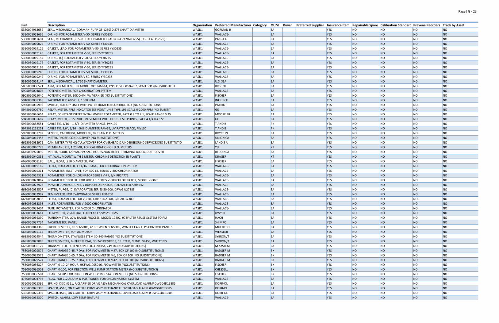
Page| G ‐ 23
Part Description Organization Preferred Manufacturer Category OUM Buyer Preferred Supplier Insurance Item Repairable Spare Calibration Standard Prevene Reorders Track by Asset5330004963652 SEAL, MECHANICAL, (GORMAN‐RUPP GS‐1250) 0.875 SHAFT DIAMETER WASD1 GORMAN‐R EA YES NO NO NO NO
5330005053665 O‐RING, FOR ROTAMETER V‐50, SERIES YY30235 WASD1 WALLACE‐ EA YES NO NO NO NO
5330050017694 SEAL, MECHANICAL, 0.590 SHAFT DIAMETER (AURORA 7120703755) (U.S. SEAL PS‐129) WASD1 PAC‐SEAL EA YES NO NO NO NO
5330050019022 O‐RING, FOR ROTAMETER V‐50, SERIES YY30235 WASD1 WALLACE‐ EA YES NO NO NO NO
5330050019126 GASKET, LEAD, FOR ROTAMETER V‐50, SERIES YY30235 WASD1 WALLACE‐ EA YES NO NO NO NO
5330050019148 GASKET, FOR ROTAMETER V‐50, SERIES YY30235 WASD1 WALLACE‐ EA YES NO NO NO NO
5330050019157 O‐RING, (C) ROTAMETER V‐50, SERIES YY30235 WASD1 WALLACE‐ EA YES NO NO NO NO
5330050019172 GASKET, FOR ROTAMETER V‐50, SERIES YY30235 WASD1 WALLACE‐ EA YES NO NO NO NO
5330050019199 GASKET, FOR ROTAMETER V‐50, SERIES YY30235 WASD1 WALLACE‐ EA YES NO NO NO NO
5330050019240 O‐RING, FOR ROTAMETER V‐50, SERIES YY30235 WASD1 WALLACE‐ EA YES NO NO NO NO
5330050019242 O‐RING, FOR ROTAMETER V 50, SERIES YY30235 WASD1 WALLACE‐ EA YES NO NO NO NO
5330050024144 SEAL, MECHANICAL, 2.750 SHAFT DIAMETER WASD1 U.S. SEA EA YES NO NO NO NO
5805050006521 ARM, FOR METEMETER MODEL OC534M‐14, TYPE C, SER #626207, SCALE 5312(NO SUBSTITUT WASD1 BRISTOL EA YES NO NO NO NO
5905050004806 POTENTIOMETER, FOR CHLORINATION SYSTEM WASD1 WALLACE‐ EA YES NO NO NO NO
5905050015040 POTENTIOMETER, 10K OHM, W/ VERNIER (NO SUBSTITUTIONS) WASD1 FISCHER EA YES NO NO NO NO
5910050038368 TACHOMETER, 60 VOLT, 1000 RPM WASD1 INELTECH EA YES NO NO NO NO
5930050035993 SWITCH, ROTARY LIMIT WITH POTENTIOMETER CONTROL BOX (NO SUBSTITUTIONS) WASD1 PATRIOT EA YES NO NO NO NO
5945050009780 RELAY, METER, RPM INDICATOR SET POINT UNIT TYPE 196,SCALE 0‐2000 RPM (NO SUBSTIT WASD1 GE EA YES NO NO NO NO
5945050026654 RELAY, CONSTANT DIFFERENTIAL W/PIPE ROTAMETER, RATE 0.9 TO 2.1, SCALE RANGE 0.25 WASD1 MOORE PR EA YES NO NO NO NO
5945050035687 RELAY, METER, 0‐150 VDC, MOVEMENT WITH DOUBLE SETPOINTS, FACE 4 1/4 X 4 1/2 WASD1 GE EA YES NO NO NO NO
5975000858551 CABLE TIE, 1/16 ‐ 1 3/4 DIAMETER RANGE, PK=100 WASD1 T AND B PK YES NO NO NO NO
5975011255251 CABLE TIE, 3.6", 1/16 ‐ 5/8 DIAMETER RANGE, UV RATED,BLACK, PK/100 WASD1 T AND B PK YES NO NO NO NO
5999050037792 SENSOR, CARTRIDGE, MODEL 99, 02 TRAIN D.O. METERS WASD1 ROYCE IN EA YES NO NO NO NO
6625050015453 METER, PROBE, CONDUCTIVITY (NO SUBSTITUTIONS) WASD1 UNION CA EA YES NO NO NO NO
6625050032972 CAN, METER,TYPE HQ‐7U,W/COVER FOR OVERHEAD & UNDERGROUND SERVICES(NO SUBSTITUTIO WASD1 LANDIS A EA YES NO NO NO NO
6625050040773 MEMBRANE KIT, 1.25 MIL, FOR CALIBRATION OF D.O. METERS WASD1 YSI KT YES NO NO NO NO
6645000925099 METER, HOUR, 120 VAC, 99999.9 HOURS,NON‐RESET, TERMINAL BLOCK, DUST COVER WASD1 REDDINGT EA YES NO NO NO NO
6665050040853 KIT, WALL MOUNT WITH 5 METER, CHLORINE DETECTION IN PLANTS WASD1 DRAGER KT YES NO NO NO NO
6680050001186 BALL, FLOAT, .250 DIAMETER, PVC WASD1 FISCHER EA YES NO NO NO NO
6680050019162 FLOAT, ROTAMETER, 1 11/16 DIAM., FOR CHLORINATION SYSTEM WASD1 WALLACE‐ EA YES NO NO NO NO
6680050019311 ROTAMETER, INLET UNIT, FOR 500 LB. SERIES V‐800 CHLORINATOR WASD1 WALLACE‐ EA YES NO NO NO NO
6680050019321 ROTAMETER, FOR CHLORINATOR SERIES V‐75, S/N RR24776 WASD1 WALLACE‐ EA YES NO NO NO NO
6680050022867 ROTAMETER, 1000 LB., FOR 2000 LB. SERIES V‐800 CHLORINATOR, MODEL V‐8020 WASD1 WALLACE‐ EA YES NO NO NO NO
6680050022928 MASTER CONTROL, UNIT, V100A CHLORINATOR, ROTAMETER A805542 WASD1 WALLACE‐ EA YES NO NO NO NO
6680050032507 METER, PURGE, (C) EVAPORATOR SERIES 50‐200, DRWG U27885 WASD1 WALLACE‐ EA YES NO NO NO NO
6680050032997 TEMPMETER, FOR EVAPORATOR SERIES #50‐200 WASD1 WALLACE‐ EA YES NO NO NO NO
6680050033036 FLOAT, ROTAMETER, FOR V‐2100 CHLORINATOR, S/N AR‐37300 WASD1 WALLACE‐ EA YES NO NO NO NO
6680050033393 INLET, ROTAMETER, FOR V‐2000 CHLORINATOR WASD1 WALLACE‐ EA YES NO NO NO NO
6680050033404 TUBE, ROTAMETER, FOR V‐2000 CHLORINATOR WASD1 WALLACE‐ EA YES NO NO NO NO
6680050033614 FLOWMETER, VISI‐FLOAT, FOR PLANT S/W SYSTEMS WASD1 DWYER EA YES NO NO NO NO
6680050036390 TURBIDIMETER, LOW RANGE PROCESS, MODEL 1720C, 973FILTER REUSE SYSTEM TO FIU WASD1 HACH EA YES NO NO NO NO
6680050037734 TACHOMETER, PANEL WASD1 SHIMPO EA YES NO NO NO NO
6680050041368 PROBE, 1 METER, 10 SENSORS, 4" BETWEEN SENSORS, W/60 FT CABLE, PS CONTROL PANELS WASD1 MULTITRO EA YES NO NO NO NO
6685050015114 THERMOMETER, FOR AC MOTOR WASD1 WEKSLER EA YES NO NO NO NO
6685050024544 THERMOMETER, STAINLESS STEM 30‐240 RANGE (NO SUBSTITUTIONS) WASD1 SYBRON/T EA YES NO NO NO NO
6685050029086 THERMOMETER, BI‐THERM DIAL, 30‐240 DEGREE F, 18 STEM, 9 IND. GLASS, W/FITTING WASD1 SYBRON/T EA YES NO NO NO NO
6685050036127 TRANSMITTER, POTENTIOMETER, 4‐20 MA, 24V DC (NO SUBSTITUTIONS) WASD1 M‐SYSTEM EA YES NO NO NO NO
7530050029572 CHART, RANGE 0‐45, 7 DAY, FOR FLOWMETER M27, BOX OF 100 (NO SUBSTITUTIONS) WASD1 BADGER M BX YES NO NO NO NO
7530050029573 CHART, RANGE 0‐65, 7 DAY, FOR FLOWMETER M6, BOX OF 100 (NO SUBSTITUTIONS) WASD1 BADGER M BX YES NO NO NO NO
7530050029574 CHART, RANGE 0‐25, 7 DAY, FOR FLOWMETER M42, BOX OF 100 (NO SUBSTITUTIONS) WASD1 BADGER M BX YES NO NO NO NO
7530050036327 CHART, 0‐10, 24 HOUR, HKTW01005016, FLOWMETER (NOSUBSTITUTIONS) WASD1 FISCHER BX YES NO NO NO NO
7530050036502 CHART, 0‐100, FOR INJECTION WELL PUMP STATION METER (NO SUBSTITUTIONS) WASD1 CHESSELL BX YES NO NO NO NO
7530050036504 CHART, STRIP, FOR INJECTION WELL PUMP STATION METER (NO SUBSTITUTIONS) WASD1 FISCHER BX YES NO NO NO NO
4730050004793 PLUG, FOR CL2 ALARM & POSITIONER, FOR CHLORINATION SYSTEM WASD1 WALLACE‐ EA YES NO NO NO NO
5360050025395 SPRING, DISC,#511, F/CLARIFIER DRIVE ASSY MECHANICAL OVERLOAD ALARM#DWG04D13885 WASD1 DORR‐OLI EA YES NO NO NO NO
5365050025396 SPACER, #510, ON CLARIFIER DRIVE ASSY MECHANICAL OVERLOAD ALARM #DWG04D13885 WASD1 DORR‐OLI EA YES NO NO NO NO
5365050025397 SPACER, #510, ON CLARIFIER DRIVE ASSY,MECHANICAL OVERLOAD ALARM # DWG04D13885 WASD1 DORR‐OLI EA YES NO NO NO NO
5930050035300 SWITCH, ALARM, LOW TEMPERATURE WASD1 WALLACE‐ EA YES NO NO NO NO
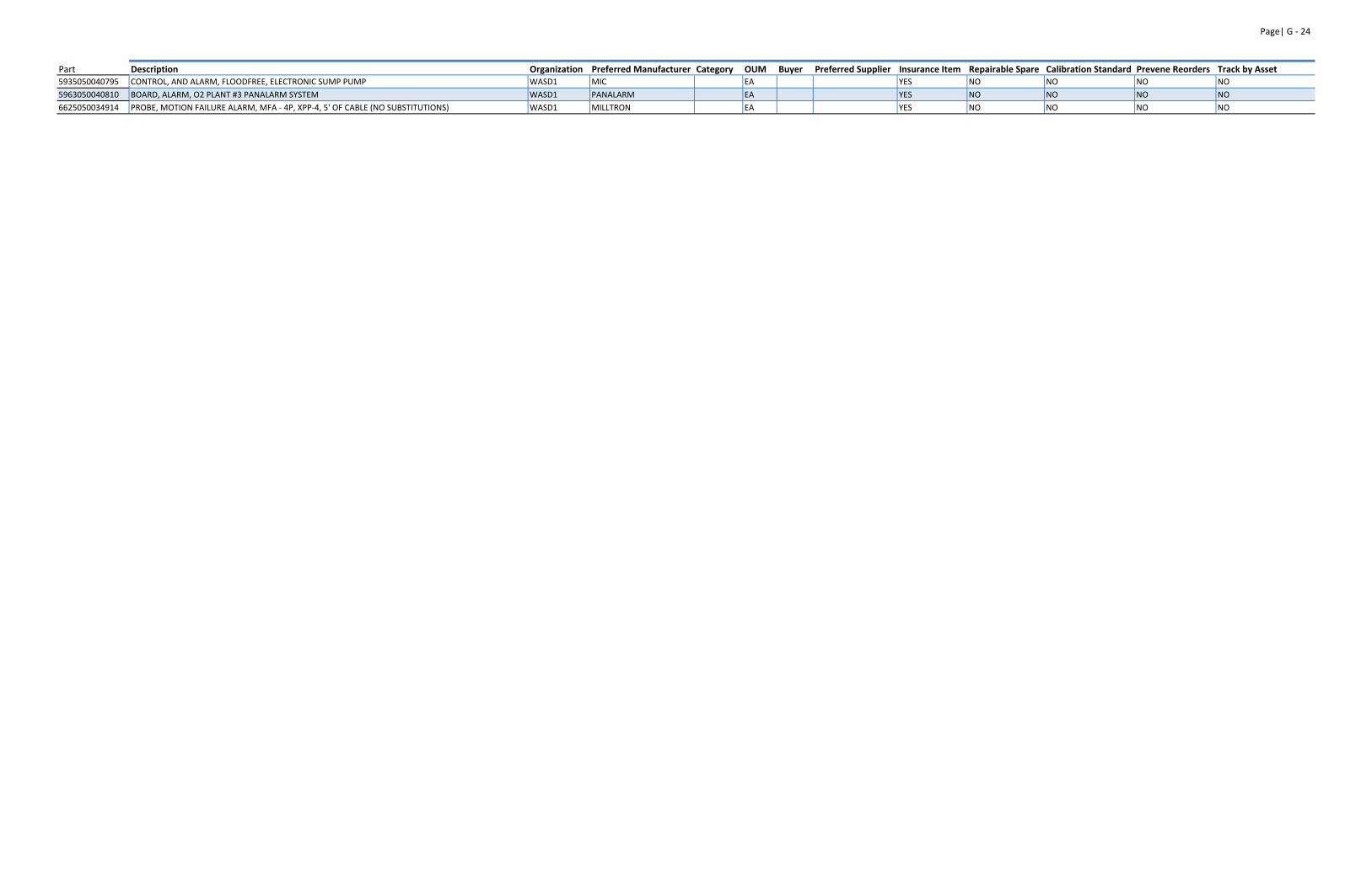
Page| G ‐ 24
Part Description Organization Preferred Manufacturer Category OUM Buyer Preferred Supplier Insurance Item Repairable Spare Calibration Standard Prevene Reorders Track by Asset5935050040795 CONTROL, AND ALARM, FLOODFREE, ELECTRONIC SUMP PUMP WASD1 MIC EA YES NO NO NO NO
5963050040810 BOARD, ALARM, O2 PLANT #3 PANALARM SYSTEM WASD1 PANALARM EA YES NO NO NO NO
6625050034914 PROBE, MOTION FAILURE ALARM, MFA ‐ 4P, XPP‐4, 5' OF CABLE (NO SUBSTITUTIONS) WASD1 MILLTRON EA YES NO NO NO NO
APPENDIX H
Pump Station Division Job List

THIS PAGE LEFT INTENTIONALLY BLANK
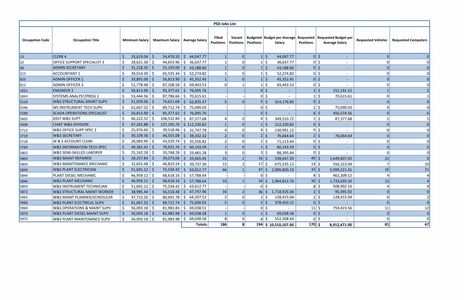
Occupation Code Occupation Title Minimum Salary Maximum Salary Average Salary Filled
Positions Vacant Positions
Budgeted Positions
Budget per Average Salary
Requested Positions
Requested Budget per Average Salary
Requested Vehicles Requested Computers
13 CLERK 4 33,619.04$ 54,476.50$ 44,047.77$ 1 0 1 44,047.77$ 0 ‐$ 0 0
22 OFFICE SUPPORT SPECIALIST 3 28,621.58$ 44,653.96$ 36,637.77$ 1 0 1 36,637.77$ 0 ‐$ 0 0
94 ADMIN SECRETARY 31,218.20$ 55,159.00$ 43,188.60$ 1 0 1 43,188.60$ 0 ‐$ 0 0
315 ACCOUNTANT 1 39,014.30$ 65,535.34$ 52,274.82$ 1 0 1 52,274.82$ 0 ‐$ 0 0
810 ADMIN OFFICER 1 33,891.00$ 56,813.90$ 45,352.45$ 1 0 1 45,352.45$ 0 ‐$ 0 0
812 ADMIN OFFICER 3 51,778.48$ 87,108.58$ 69,443.53$ 0 1 1 69,443.53$ 0 ‐$ 0 0
1021 ENGINEER 2 56,813.90$ 95,377.62$ 76,095.76$ ‐ ‐ 0 ‐$ 2 152,191.52$ 1 2
1843 SYSTEMS ANALYST/PROG 1 53,444.56$ 87,786.66$ 70,615.61$ ‐ ‐ 0 ‐$ 1 70,615.61$ 0 1
5526 W&S STRUCTURAL MAINT SUPV 51,059.06$ 74,611.68$ 62,835.37$ 5 0 5 314,176.85$ 0 ‐$ 0 0
5546 WS INSTRUMENT TECH SUPV 61,667.32$ 89,712.74$ 75,690.03$ ‐ ‐ 0 ‐$ 1 75,690.03$ 0 0
5589 SCADA OPERATIONS SPECIALIST 56,813.90$ 95,377.62$ 76,095.76$ ‐ ‐ 0 ‐$ 6 456,574.56$ 0 6
5605 ASST W&S SUPT 66,222.52$ 108,532.84$ 87,377.68$ 4 0 4 349,510.72$ 1 87,377.68$ 1 1
5608 CHIEF W&S DIVISION 87,265.88$ 137,195.76$ 112,230.82$ 1 0 1 112,230.82$ 0 ‐$ 0 0
5712 W&S OFFICE SUPP SPEC 2 25,976.60$ 39,518.96$ 32,747.78$ 4 0 4 130,991.12$ 0 ‐$ 0 0
5719 W&S SECRETARY 30,109.56$ 46,555.08$ 38,332.32$ 2 0 2 76,664.64$ 2 76,664.64$ 0 0
5728 W & S ACCOUNT CLERK 28,083.90$ 43,029.74$ 35,556.82$ 2 0 2 71,113.64$ 0 ‐$ 0 0
5784 W&S INFORMATION TECH SPEC 49,365.42$ 70,921.76$ 60,143.59$ 1 0 1 60,143.59$ 0 ‐$ 0 0
5802 W&S SEMI‐SKILLED LABORER 25,162.28$ 33,768.28$ 29,465.28$ 3 0 3 88,395.84$ 0 ‐$ 0 0
5803 W&S MAINT REPAIRER 28,257.84$ 39,073.06$ 33,665.45$ 15 1 16 538,647.20$ 49 1,649,607.05$ 22 0
5804 W&S MAINTENANCE MECHANIC 32,655.48$ 46,819.24$ 39,737.36$ 15 2 17 675,535.12$ 14 556,323.04$ 7 10
5840 W&S PLANT ELECTRICIAN 51,691.12$ 75,534.42$ 63,612.77$ 46 1 47 2,989,800.19$ 33 2,099,221.41$ 16 21
5844 PLANT DIESEL MECHANIC 46,959.12$ 68,618.16$ 57,788.64$ ‐ ‐ 0 ‐$ 8 462,309.12$ 4 4
5846 W&S PLANT MECHANIC 46,959.12$ 68,618.16$ 57,788.64$ 33 1 34 1,964,813.76$ 30 1,733,659.20$ 15 45850 W&S INSTRUMENT TECHNICIAN 51,691.12$ 75,534.42$ 63,612.77$ ‐ ‐ 0 ‐$ 8 508,902.16$ 4 4
5872 W&S STRUCTURAL MAINT WORKER 38,985.44$ 56,510.48$ 47,747.96$ 34 2 36 1,718,926.56$ 2 95,495.92$ 0 0
5965 W&S MAINT PLANNER/SCHEDULER 47,723.26$ 80,691.78$ 64,207.52$ 2 0 2 128,415.04$ 2 128,415.04$ 0 2
5966 W&S PLANT ELECTRICAL SUPV 61,667.32$ 89,712.74$ 75,690.03$ 5 0 5 378,450.15$ 0 ‐$ 0 0
5969 W&S OPERATIONS & MAINT SUPV 56,093.18$ 81,983.83$ 69,038.51$ ‐ ‐ 0 ‐$ 11 759,423.56$ 11 12
5970 W&S PLANT DIESEL MAINT SUPV 56,093.18$ 81,983.98$ 69,038.58$ 1 0 1 69,038.58$ 0 ‐$ 0 0
5972 W&S PLANT MAINTENANCE SUPV 56,093.18$ 81,983.98$ 69,038.58$ 8 0 8 552,308.64$ 0 ‐$ 0 0
Totals: 186 8 194 10,510,107.00$ 170 8,912,471.00$ 81 67
PSD Jobs List

THIS PAGE LEFT INTENTIONALLY BLANK

APPENDIX I
ANTICIPATED FUNDING NEEDS

THIS PAGE LEFT INTENTIONALLY BLANK
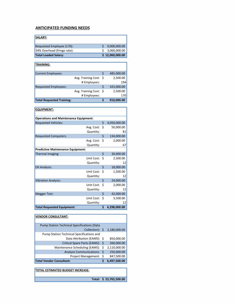
ANTICIPATED FUNDING NEEDS
SALARY:
Requested Employee (170): 9,000,000.00$ 34% Overhead (fringe rate): 3,060,000.00$ Total Loaded Salary: 12,060,000.00$
TRAINING:
Current Employees: 485,000.00$ Avg. Training Cost: 2,500.00$
# Employees: 194Requested Employees: 425,000.00$
Avg. Training Cost: 2,500.00$ # Employees: 170
Total Requested Training: 910,000.00$
EQUIPMENT:
Operations and Maintenance Equipment:Requested Vehicles: 4,050,000.00$
Avg. Cost: 50,000.00$ Quantity: 81
Requested Computers: 134,000.00$ Avg. Cost: 2,000.00$ Quantity: 67
Predictive Maintenance Equipment:Thermal Imaging: 30,000.00$
Unit Cost: 2,500.00$ Quantity: 12
Oil Analysis: 18,000.00$ Unit Cost: 1,500.00$ Quantity: 12
Vibration Analysis: 24,000.00$ Unit Cost: 2,000.00$ Quantity: 12
Megger Test: 42,000.00$ Unit Cost: 3,500.00$ Quantity: 12
Total Requested Equipment: 4,298,000.00$
VENDOR CONSULTANT:
Pump Station Technical Specifications (Data Collection): 2,180,000.00$
Pump Station Technical Specifications and Data Attribution (EAMS): 850,000.00$
Critical Spare Parts (EAMS): 260,000.00$ Maintenance Scheduling (EAMS): 2,110,000.00$
Analyze Communications: 250,000.00$ Project Management: 847,500.00$
Total Vendor Consultant: 6,497,500.00$
TOTAL ESTIMATED BUDGET INCREASE:
Total: 23,765,500.00$

THIS PAGE LEFT INTENTIONALLY BLANK

THIS PAGE LEFT INTENTIONALLY BLANK