Embed Size (px)
Citation preview
VI. TUBE RESEARCH AND DEVELOPMENT
A. MAGNETRON DEVELOPMENT
Prof. S. T. Martin J. G. Lawton
A. G. Barrett R. R. Moats
D. L. Eckhardt R. J. Renfrow
1. High-Power 10.7-Cm Magnetron
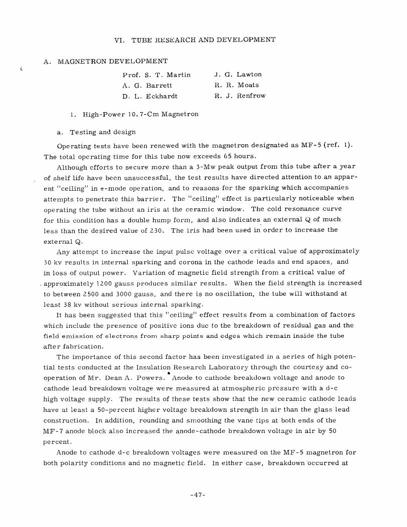
a. Testing and design
Operating tests have been renewed with the magnetron designated as MF-5 (ref. 1).
The total operating time for this tube now exceeds 65 hours.
Although efforts to secure more than a 3-Mw peak output from this tube after a year
of shelf life have been unsuccessful, the test results have directed attention to an appar-
ent "ceiling" in Tr-mode operation, and to reasons for the sparking which accompanies
attempts to penetrate this barrier. The "ceiling" effect is particularly noticeable when
operating the tube without an iris at the ceramic window. The cold resonance curve
for this condition has a double hump form, and also indicates an external Q of much
less than the desired value of 230. The iris had been used in order to increase the
external Q.
Any attempt to increase the input pulse voltage over a critical value of approximately
30 kv results in internal sparking and corona in the cathode leads and end spaces, and
in loss of output power. Variation of magnetic field strength from a critical value of
approximately 1200 gauss produces similar results. When the field strength is increased
to between 2500 and 3000 gauss, and there is no oscillation, the tube will withstand at
least 38 kv without serious internal sparking.
It has been suggested that this "ceiling" effect results from a combination of factors
which include the presence of positive ions due to the breakdown of residual gas and the
field emission of electrons from sharp points and edges which remain inside the tube
after fabrication.
The importance of this second factor has been investigated in a series of high poten-
tial tests conducted at the Insulation Research Laboratory through the courtesy and co-
operation of Mr. Dean A. Powers. Anode to cathode breakdown voltage and anode to
cathode lead breakdown voltage were measured at atmospheric pressure with a d-c
high voltage supply. The results of these tests show that the new ceramic cathode leads
have at least a 50-percent higher voltage breakdown strength in air than the glass lead
construction. In addition, rounding and smoothing the vane tips at both ends of the
MF-7 anode block also increased the anode-cathode breakdown voltage in air by 50
percent.
Anode to cathode d-c breakdown voltages were measured on the MF-5 magnetron for
both polarity conditions and no magnetic field. In either case, breakdown occurred at
-47-
(VI. TUBE RESEARCH AND DEVELOPMENT)
approximately 18 kv. It is significant that these static tests produced sparking and
corona phenomena essentially identical to those obtained with pulsed operation.
The observed difference between d-c and pulsed operation breakdown voltages is
believed to be due to the following factors which are present in the latter case.
1. Voltage is applied for such short intervals (1 [sec) and so infrequently
(120 pps) that conduction due to collision ionization and field emission cannot get started
until relatively high voltages are applied to the tube.
2. The modulator is a low impedance source which can maintain a relatively
high voltage while supplying corona and sparking losses.
3. The axial magnetic field tends to lengthen the electron paths and thereby to
increase the breakdown voltage.
Preliminary experiments with straight butt-type metal-ceramic seals for use in
cathode leads met with variable success as explained in the Quarterly Progress Report,
January 15, 1950. The reason for the cracking of the ceramic was traced to a discon-
tinuous expansion characteristic of the type 430 stainless steel used as the metal part
of the seal (2). A 28-percent chrome -steel alloy closely matches the expansion of the
ceramic, ALSIMAG 243, and has a smooth and reversible expansion characteristic.
This alloy is made by the Allegheny Ludlum Steel Corp. and is known as SEALMET No. 1.
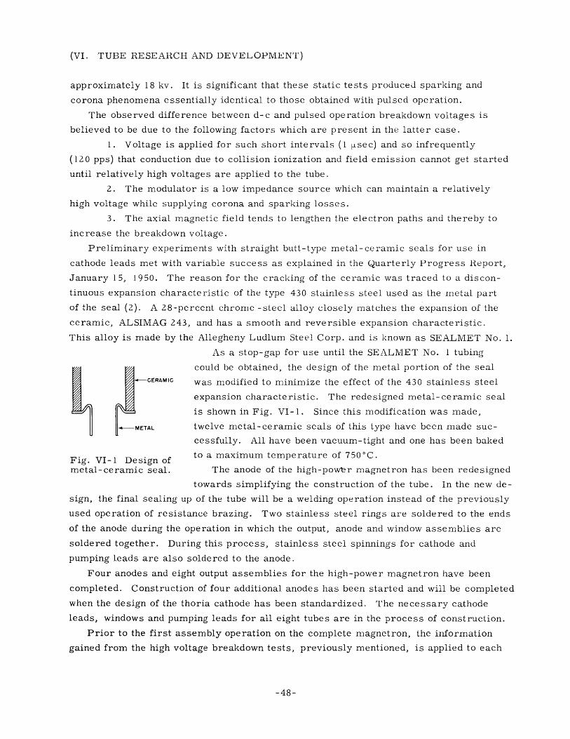
As a stop-gap for use until the SEALMET No. 1 tubing
could be obtained, the design of the metal portion oI the sealIC was modified to minimize the effect of the 430 stainless steel
expansion characteristic. The redesigned metal-ceramic seal
is shown in Fig. VI-1. Since this modification was made,
twelve metal-ceramic seals of this type have been made suc-
cessfully. All have been vacuum-tight and one has been baked
Fig. VI-l1 Design of to a maximum temperature of 750 0 C.
metal-ceramic seal. The anode of the high-power magnetron has been redesigned
towards simplifying the construction of the tube. In the new de-
sign, the final sealing up of the tube will be a welding operation instead of the previously
used operation of resistance brazing. Two stainless steel rings are soldered to the ends
of the anode during the operation in which the output, anode and window assemblies are
soldered together. During this process, stainless steel spinnings for cathode and
pumping leads are also soldered to the anode.
Four anodes and eight output assemblies for the high-power magnetron have been
completed. Construction of four additional anodes has been started and will be completed
when the design of the thoria cathode has been standardized. The necessary cathode
leads, windows and pumping leads for all eight tubes are in the process of construction.
Prior to the first assembly operation on the complete magnetron, the information
gained from the high voltage breakdown tests, previously mentioned, is applied to each
-48-
(VI. TUBE RESEARCH AND DEVELOPMENT)
anode. The vane tips at both ends of the anode block will be rounded off as standard
practice on all future magnetrons.
b. Thoria cathodes
The end-mounts for mounting thoria cathodes in the magnetron have been redesigned
in order to give good high-voltage design and to minimize the overall length of the
cathode assembly.
A full-sized cathode was mounted in a diode, the construction of which approximated
that of the magnetron, and tests on cathode power vs. temperature were conducted. The
diode was then pulsed to 7000 volts at 1600°B. Measurements indicated that the cathode
resistance was lower than anticipated by a factor of 5, and the emission was well below
the space charge limitation value.
The cathode failed after about 36 hours of operation. Examination of the cathode,
when the tube was opened, showed that a hot spot had existed at a point on the cathode
outside the range of observation, and that this had boiled a considerable amount of
molybdenum away at that point, causing failure. The failure was apparently caused by
stratification of the ca ode by vibration of the die during loading in the manufacturing
operation. The hot s;pot appeared at a thoria-rich section of the cathode, where the
resistance was high. In the future, the die will be loaded without vibration in packing
the powder into the die.
c. Auxiliary equipment
The new inductor for the l-tsec pulse-forming network has been constructed, in-
stalled, tested and put into service in tests of the MF-5 magnetron.
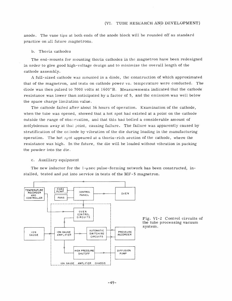
Fig. VI-2 Control circuits ofthe tube processing vacuumsystem.
-49-
(VI. TUBE RESEARCH AND DEVELOPMENT)
A new 20-Mw pulse transformer wound with a 3:1 turn ratio has been ordered.
Except for the turns ratio, this transformer is identical with the 4:1 transformer men-
tioned in a previous progress report.
The control circuits for the tube processing vacuum system have been redesigned
and rebuilt. Fig. VI-2 is a block diagram of the components used in the complete
system.
A Brown Instrument Co. recorder and controller is used to regulate the temperature
of the "bake-out" oven. An oven control circuit turns off the oven if pressure in the-4 -
vacuum system rises above 2. 5 x 104 mm Hg. When the pressure falls to 1 X 10⁻⁴
mm Hg, this circuit turns on the power to the oven. Should the pressure for any reason-4
rise to a value higher than 5 X 10⁻⁴ mm Hg, or if there should be a temporary power
failure, the high pressure shut-off circuit will turn off the ion gauge amplifier, diffusion
pump and oven. These units must then be turned on manually.
A Celect Ray four-channel recorder is used to record pressure in the vacuum system
over a range of four decades. The automatic switching circuits on the ion gauge ampli-
fier chassis determine the sequence and frequency with which pressure on the four dif-
ferent ranges is read by the recorder.
The use of a standard S-band waveguide output on the magnetron has made necessary
a change in the r-f test equipment for testing the tubes. Part of this equipment has been
constructed; all of it will be available for processing and testing the next tube.
2. Magnetron Research
a. Mode interaction in magnetrons
Interaction tests of the type described in the Quarterly Progress Report, January 15,
1950 have been performed for another 718-EY magnetron, first for normal loading, and
then for a more lightly loaded nr-mode. Power measurements were made for each con-
dition of loading for the same applied voltage, and relative r-f voltages on the magnetron
anode were computed.
Theoretical considerations (3) for non-linear oscillators suggest that oscillation in
one mode should tend to load any other mode, and that the greater the amplitude of oscil-
lation, the greater should be this effect. Therefore, in the tests described above, the
loading of the n = 3 mode produced by the presence of r-mode oscillation should be
greater for the lightly loaded ir-mode, where the magnitude of r-f voltage within the mag-
netron is greater, than for the normally loaded ir-mode. The standing-wave measure-
ments of the n = 3 mode in the presence of r-mode oscillations, normally loaded, led to
various values of loaded Q for n = 3, depending on the method of calculation. Two
methods of calculation showed that the smaller amplitude of 7r-mode oscillation had more
effect upon loading the n = 3 mode, while another gave opposite results which agreed
50-
(VI. TUBE RESEARCH AND DEVELOPMENT)
more nearly with those predicted theoretically.
Oscillation in this 718-EY magnetron was found to be relatively weak and inefficient,
and at the same time very noisy. X-ray photographs showed that the cathode was con
siderably off center. The experiment is being repeated, using a 2J32 magnetron.
A mode shift test has been made, using the 2J54, an eight hole-and-slot, single
strapped, tunable S- band magnetron. This magnetron was found to oscillate in the
'( = 5 component of the n = 3 mode (5/3/8) for low input currents under some conditions.
The shift from the 5/3/8 mode to the 1T-mode (4/4/8) was examined and photographed;
the output of a wide-band diode detector directly on the plates of a P-5 sYnchroscope
was used in order to observe the r-f envelope of the magnetron output. No cessation
of oscillation was observed during the transition. This observation seemed to indicate
some degree of competition between modes. It was further observed that this mode shift
is primarily a function of conditions in the 1T-mode, the final mode in the mode shift,
rather than of the original mode. The latter observation is in contrast to results ob
tained previously with a low-power rising-sun magnetron (4).
The non-linear oscillator theory discussed above (3) may be consistent with a mode
change depending primarily on either the original mode or the final mode. In the 2J54,
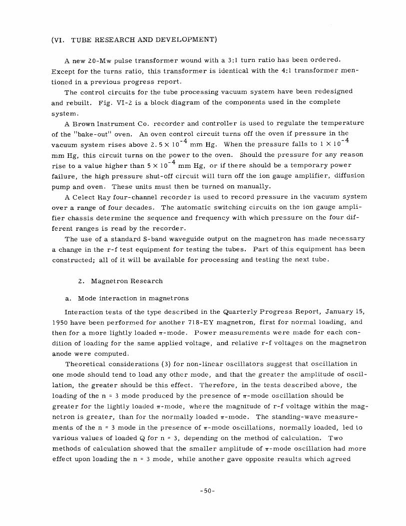
oscillation in the 5/3/8 mode has little vitality. However, synchroscope observations
of the r-f envelope (e. g. Fig. VI-3) show that if the 5/3/8 mode can start ahead of the
Fig. VI-3 R-F envelope, 2J54 magnetron. Oscillation starts in 5/3/8 mode, then shifts to 1Tmode (4/4/8). Pulse duration approximately2 I-lsec.
1T-mode, it will delay the starting of the 1T-mode appreciably. Thus, here is an example
of one mode merely being delayed in starting, rather than being suppressed, by the
presence of oscillation in another mode.
The contemplated use of the micro-oscillograph for observation of mode transitions
has been postponed indefinitely, due to leaks in the vacuum system. A P- 5 synchroscope
used in combination with a broad-band diode detector, as described above, has been used
as a substitute with some degree of success. The time constant of the detector is esti
mated to be considerably less than the time constants usually observed for build-up and
decay of oscillations in S-band magnetrons.
-51-
(VI. TUBE RESEARCH AND DEVELOPMENT)
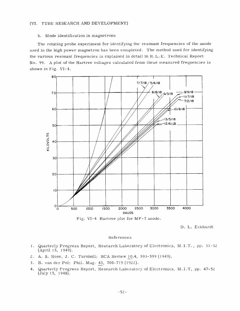
b. Mode identification in magnetrons
The rotating probe experiment for identifying the resonant frequencies of the anode
used in the high power magnetron has been completed. The method used for identifying
the various resonant frequencies is explained in detail in R. L.E. Technical Report
No. 99. A plot of the Hartree voltages calculated from these measured frequencies is
shown in Fig. VI-4.
cO
J
o
d
0 500 1000 1500 2000 2500 3000 550U 4UUuGAUSS
Fig. VI-4 Hartree plot for MF-7 anode.
D. L. Eckhardt
References
1i. Quarterly Progress Report, Research Laboratory of Electronics,(April 15, 1949).
2. A. S. Rose, J. C. Turnbull: RCA Review 10:4, 593-599 (1949).
3. B. van der Pol: Phil. Mag. 43, 700-719 (1922).
4. Quarterly Progress Report, Research Laboratory of Electronics,(July 15, 1948).
M.I.T., pp. 31-32
M.I.T, pp. 47-52
-52-
(VI. TUBE RESEARCH AND DEVELOPMENT)
B. MICROWAVE TUBES
L. D. Smullin G. W. Zeoli
L. A. Harris
1. Microwave Noise Studies
This work has been completed and submitted as a Master's thesis in the Electrical
Engineering department by Mr. Karp.
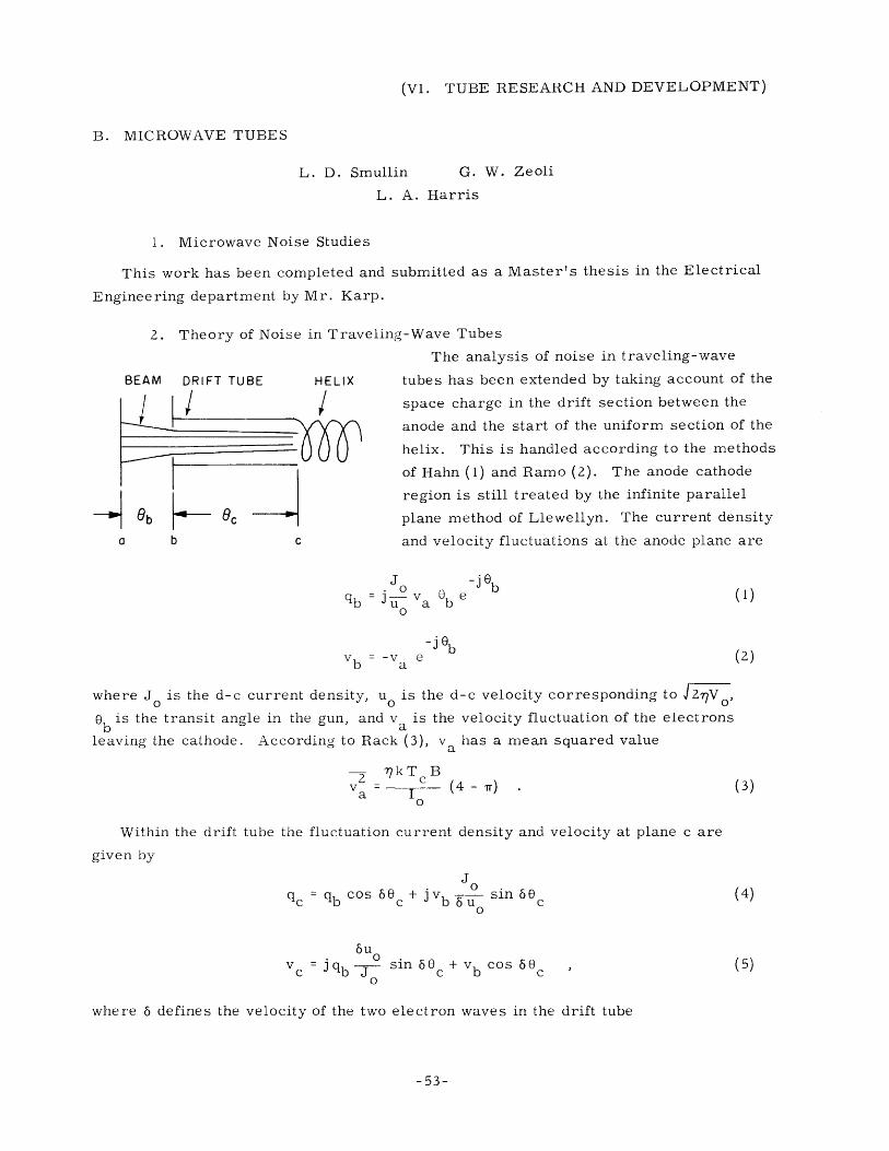
2. Theory of Noise in Traveling-Wave Tubes
The analysis of noise in traveling-wave
BEAM DRIFT TUBE HELIX tubes has been extended by taking account of the
space charge in the drift section between the
anode and the start of the uniform section of the
helix. This is handled according to the methods
of Hahn (1) and Ramo (2). The anode cathode
region is still treated by the infinite parallel
Ob 8c plane method of Llewellyn. The current density
a b c and velocity fluctuations at the anode plane are
J -jeb
b b0
vb = -v eb -a
-j b
(1)
(2)
where J is the d-c current density, u0 is the d-c velocity corresponding to J2,Vo,ob is the transit angle in the gun, and va is the velocity fluctuation of the electrons
leaving the cathode. According to Rack (3), va has a mean squared value
2 ?kTcBv2 c (4 - Tr) (3)
Within the drift tube the fluctuation current density
given by
and velocity at plane c are
0qc b cos 6c + jvb 6u sin
6uvc b= qb sin 60 + v b cos 60c
where 6 defines the velocity of the two electron waves in the drift tube
-53-
(4)
(5)
(VI. TUBE RESEARCH AND DEVELOPMENT)
P - (1 + 6)
and is defined explicitly in ref. 2.
Using Eqs. 1 and 2, Eqs. 4 and 5 may be rewritten
v Ja o
qc = j ub0
(60b cos 6e c - sin 56c)
ve = -Va(60 b sin 60 c + cos 6 c)
The growing wave excited in the helix by these components is
Vo Iq C uo20 C J o0 o Z 2/
(8)
3( +j )-Z
C (V V2P o C °----a0 U
o
0b cos 6 0sin 6 0
c (1I
-
3 +
j-2+ (cos 6 0 c + 66 b sin 60c)
F 2j 2)(8)
The mean square value of this is
l 2 C2 VC 2 v2240 VO a9u "
whe re
(1 + z)(1 + p2 ) + (1 - p 2 )(1 - 2) +
(i - a0) + i3 c(p - 1)sin 2 6 0 c
2, po cos 2 6 0 c
(10)
Cy= ,
The minimum and maximum values of IA IZ will occur at
2p(1 - 52) + 3 o(p 2 - 1)
c (1 - p2)(1 - 2Z ) + 21 pd
so that
-54-
IA12
IA12 =
+ [Zp
and
(9)
tan 260 (11)
E =1
2 23 j
p = 5 9 b
i
(VI. TUBE RESEARCH AND DEVELOPMENT)
Ali 1(1+p2)(1 )+ 1+i2+4 . (12)
max
The noise figure of the amplifier is defined by the ratio
IE1l + IEl7TF =
T
where E 1 12 is the noise power induced from the antenna resistance. Then we get
T0.215 T 2
F = 1 + T c (13)
where Tc and T are the temperatures of the cathode and of the antenna impedance; and
0.215 T( 2) ( 1 + 0 2) 1+2+4
mi n T C
From this we find that for the best noise figure p = 6 0 b and 6 = C/S should be small,
while C should be large. For ordinary geometries and currents C and 6 are of the same
order of magnitude, about 0. 01 to 0. 02. p can be made small by decreasing 0 b, which
amounts to reducing the cathode area, if the voltage and current are held constant.
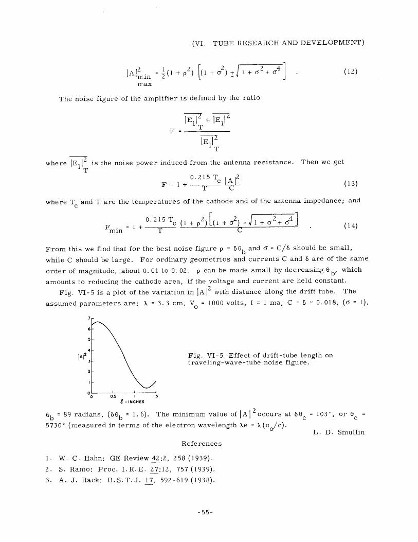
Fig. VI-5 is a plot of the variation in I A 2 with distance along the drift tube. The
assumed parameters are: X = 3.3 cm, V0 1000 volts, I = 1 ma, C = 5 = 0. 018, ( = 1),
7
6
5
4
JA123
2
0
Fig. VI-5 Effect of drift-tube length ontraveling-wave-tube noise figure.
- INCHES
6 b 89 radians, (66 b = 1. 6). The minimum value of IA loccurs at 6 0c 1030, or 0 =
57300 (measured in terms of the electron wavelength ke = k(u /C). L. D. Smullin
References
1. W. C. Hahn: GE Review 42:2, 258 (1939).
2. S. Ramo: Proc. I.R.E. 27:12, 757 (1939).
3. A. J. Rack: B.S.T.J. 17, 592-619 (1938).
-55-
(VI. TUBE RESEARCH AND DEVELOPMENT)
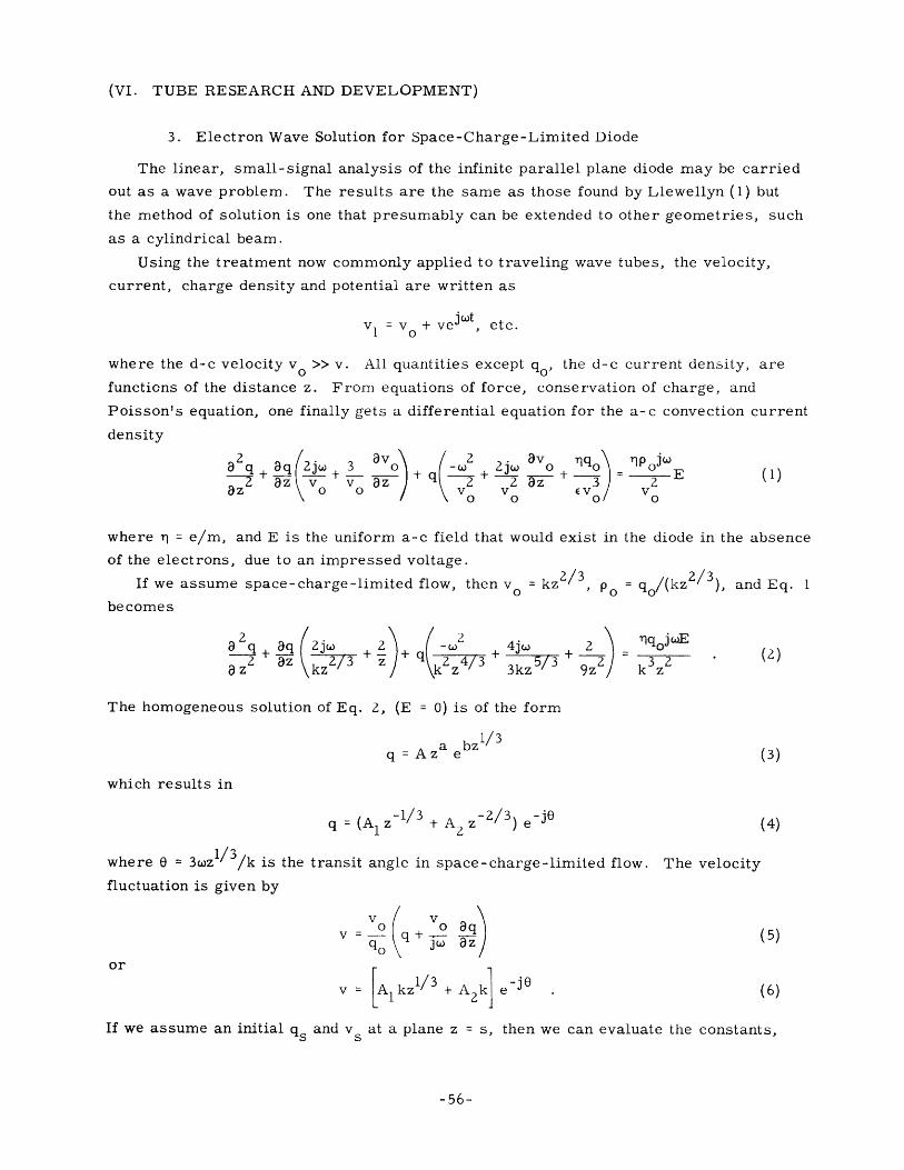
3. Electron Wave Solution for Space-Charge-Limited Diode
The linear, small-signal analysis of the infinite parallel plane diode may be carried
out as a wave problem. The results are the same as those found by Llewellyn (1) but
the method of solution is one that presumably can be extended to other geometries, such
as a cylindrical beam.
Using the treatment now commonly applied to traveling wave tubes, the velocity,
current, charge density and potential are written as
jwtv I = v + ve , etc.
where the d-c velocity v 0 >> v. All quantities except q , the d-c current density, are
functions of the distance z. From equations of force, conservation of charge, and
Poisson's equation, one finally gets a differential equation for the a-c convection current
density
2 q av - 2+ 2jw avo q0 oj + -3 + E (1)2 az v v 3z + 2 _ - 3 2(1)
a8z v0 v EV V
where r~ = e/m, and E is the uniform a-c field that would exist in the diode in the absence
of the electrons, due to an impressed voltage.
If we assume space-charge-limited flow, then v = kz2/3 P0 o/(kz/3), and Eq. 1
becomes
a q 3q 2jw 2 5/ 3 + 32 (2)az2 z k 2/ 3 z+ 24/3 3 /a zZ 3kz z 2
The homogeneous solution of Eq. 2, (E = 0) is of the form
a bz1/3q = Az e (3)
which results in
q = (A 1 z1/3 + A z-2/3) e-j (4)
where 0 = 3wz /3/k is the transit angle in space-charge-limited flow. The velocity
fluctuation is given by
v ( v ao o 8qv=-- q + q (5)
or
v Al kzl/3 + A 2 k e-j (6)
If we assume an initial qs and v s at a plane z = s, then we can evaluate the constants,
-56-
(VI. TUBE RESEARCH AND DEVELOPMENT)
and the result is
q ={s L( 1/3 2/3 + v z(-1/3 - sl3) e (7)
sk s/3 s 2s jv = -+ vs (-z)1 e-4 (8)3 - 13° 1 33 0 z/3j /3)
where = - Os = (zl/3 - s 3).k2/3
We have assumed small signal conditions, i.e. v << v o. Since v = kz , we cannot
let z = 0 and still have a finite v . However, we can let s << z, in which cases
3jwqo j s -e-q v = -je qo (9)s ,k2z13 e V
v"' - v e- j (10)
These are, of course, the same results which Llewellyn obtains.
The inhomogeneous solution (E / 0) may be found by standard methods (2), and again
the results are like Llewellyn's. Although the results thus far are not new, it is hoped
that this method eventually may be extended to the case of a cylindrical beam or even of
a conical beam. L. D. Smullin
References
1. F. B. Llewellyn: Electron Inertia Effects (Cambridge Univ. Press, 1943).
2. F. S. Woods: Advanced Calculus, pp. 255-256 (Ginn Co., Boston, 1934).
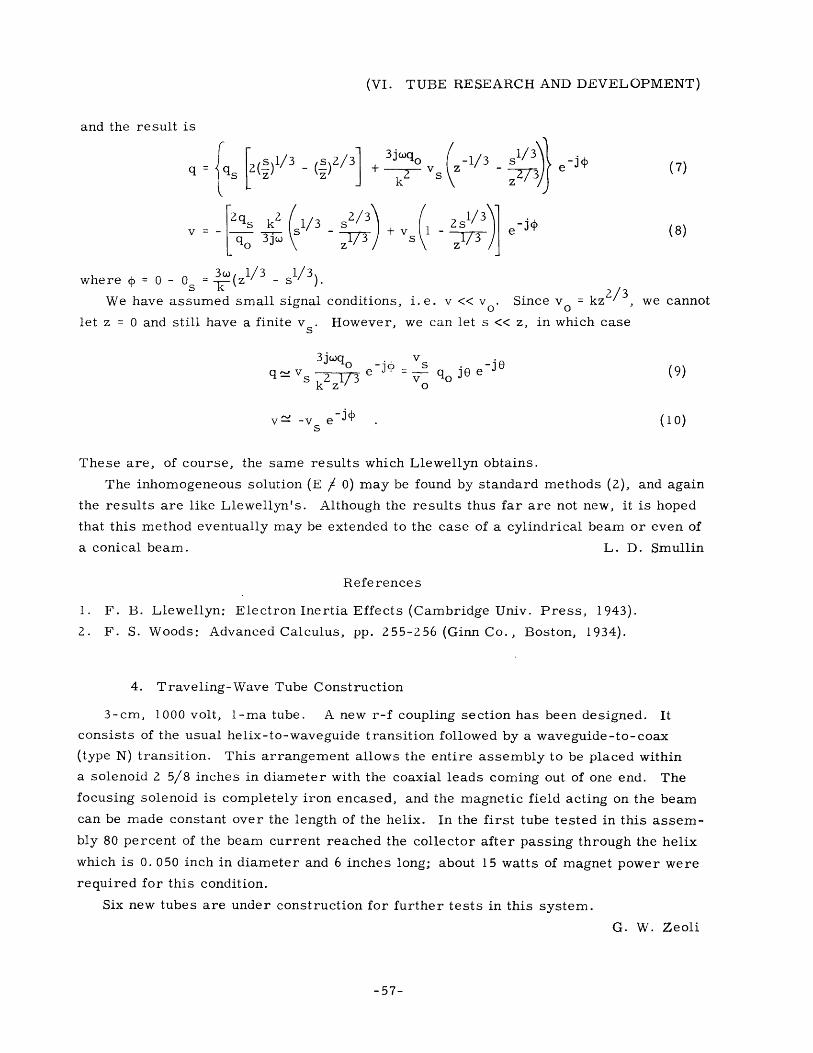
4. Traveling-Wave Tube Construction
3-cm, 1000 volt, 1-ma tube. A new r-f coupling section has been designed. It
consists of the usual helix-to-waveguide transition followed by a waveguide-to-coax
(type N) transition. This arrangement allows the entire assembly to be placed within
a solenoid 2 5/8 inches in diameter with the coaxial leads coming out of one end. The
focusing solenoid is completely iron encased, and the magnetic field acting on the beam
can be made constant over the length of the helix. In the first tube tested in this assem-
bly 80 percent of the beam current reached the collector after passing through the helix
which is 0. 050 inch in diameter and 6 inches long; about 15 watts of magnet power were
required for this condition.
Six new tubes are under construction for further tests in this system.
G. W. Zeoli
-57-
(VI. TUBE RESEARCH AND DEVELOPMENT)
5. Dense Electron Beams in Axial Magnetic Fields
a. Theory
The theoretical work is essentially complete and is being written up. Explicit design
formulae for the various special cases of practical interest are derived and the numeri-
cal values for the proposed experiments are computed from these formulae.
b. Experiment
The electron gun for the experiments has been tested and found satisfactory and
suitable for all of the experiments. The transmission efficiency is over 90 percent, and
the design current of 0. 5 amp is drawn with an anode voltage of 1000 volts. Another test
is planned to determine the effect of some added lens plates.
The vacuum system has caused considerable delay because of its low pumping speed;
modifications are in progress.
A pulsed power supply is complete and functions satisfactorily, operating the tube
with a duty ratio of 0. 01. The measuring circuits are being built into a panel unit.
Drift tubes, collectors, centering rings, insulators and other hardware for use in
the tubes are almost completed. After the transition regions are designed, all the appa-
ratus should be ready for the completion of the tests.
L. A. Harris
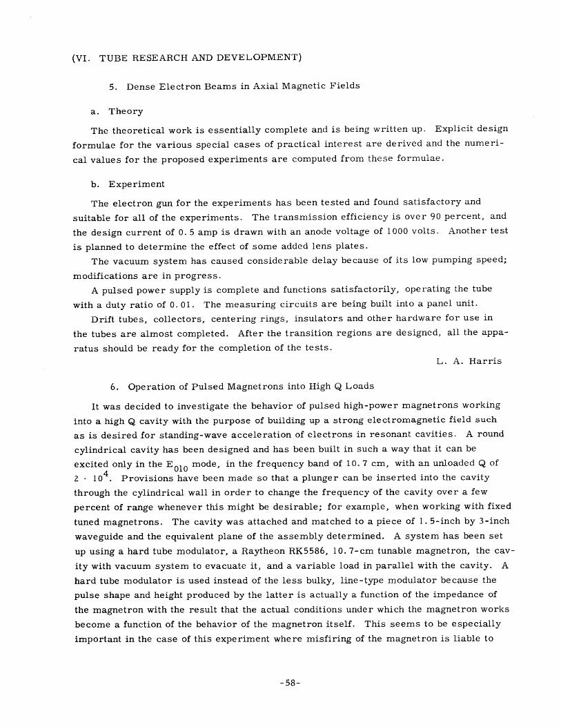
6. Operation of Pulsed Magnetrons into High Q Loads
It was decided to investigate the behavior of pulsed high-power magnetrons working
into a high Q cavity with the purpose of building up a strong electromagnetic field such
as is desired for standing-wave acceleration of electrons in resonant cavities. A round
cylindrical cavity has been designed and has been built in such a way that it can be
excited only in the E010 mode, in the frequency band of 10. 7 cm, with an unloaded Q of4
2 - 104. Provisions have been made so that a plunger can be inserted into the cavity
through the cylindrical wall in order to change the frequency of the cavity over a few
percent of range whenever this might be desirable; for example, when working with fixed
tuned magnetrons. The cavity was attached and matched to a piece of 1. 5-inch by 3-inch
waveguide and the equivalent plane of the assembly determined. A system has been set
up using a hard tube modulator, a Raytheon RK5586, 10. 7-cm tunable magnetron, the cav
ity with vacuum system to evacuate it, and a variable load in parallel with the cavity. A
hard tube modulator is used instead of the less bulky, line-type modulator because the
pulse shape and height produced by the latter is actually a function of the impedance of
the magnetron with the result that the actual conditions under which the magnetron works
become a function of the behavior of the magnetron itself. This seems to be especially
important in the case of this experiment where misfiring of the magnetron is liable to
-58-
(VI. TUBE RESEARCH AND DEVELOPMENT)
happen with the consequences, when using a line-type modulator, of voltage overshoot,
sparking of the magnetron and damaging the cathode.
A first objective of the experiment is to determine the building-up of the cavity field
as a function of the shunt load. When the most favorable working conditions of the mag-
netron and the attached circuits are established, the experiments will be repeated with
the line type modulator. H. Krusemeijer
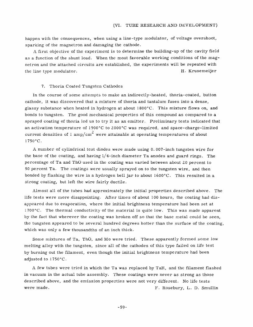
7. Thoria Coated Tungsten Cathodes
In the course of some attempts to make an indirectly-heated, thoria-coated, button
cathode, it was discovered that a mixture of thoria and tantalum fuses into a dense,
glassy substance when heated in hydrogen at about 1800 0 C. This mixture flows on, and
bonds to tungsten. The good mechanical properties of this compound as compared to a
sprayed coating of thoria led us to try it as an emitter. Preliminary tests indicated that
an activation temperature of 1900'C to 2000 0 C was required, and space-charge-limited
current densities of 1 amp/cm 2 were attainable at operating temperatures of about
1750 0 C.
A number of cylindrical test diodes were made using 0. 007-inch tungsten wire for
the base of the coating, and having 1/4-inch diameter Ta anodes and guard rings. The
percentage of Ta and ThO used in the coating was varied between about 20 percent to
50 percent Ta. The coatings were usually sprayed on to the tungsten wire, and then
bonded by flashing the wire in a hydrogen bell jar to about 1600 0 C. This resulted in a
strong coating, but left the wire fairly ductile.
Almost all of the tubes had approximately the initial properties described above. The
life tests were more disappointing. After times of about 100 hours, the coating had dis-
appeared due to evaporation, where the initial brightness temperature had been set at
1700'C. The thermal conductivity of the material is quite low. This was made apparent
by the fact that wherever the coating was broken off so that the base metal could be seen,
the tungsten appeared to be several hundred degrees hotter than the surface of the coating,
which was only a few thousandths of an inch thick.
Some mixtures of Ta, ThO, and Mo were tried. These apparently formed some low
melting alloy with the tungsten, since all of the cathodes of this type failed on life test
by burning out the filament, even though the initial brightness temperature had been
adjusted to 1750'C.
A few tubes were tried in which the Ta was replaced by TaH, and the filament flashed
in vacuum in the actual tube assembly. These coatings were never as strong as those
described above, and the emission properties were not very different. No life tests
were made. F. Rosebury, L. D. Smullin
-59-
(VI. TUBE RESEARCH AND DEVELOPMENT)
C. THE GENERATION OF MILLIMETER AND INFRARED RADIATION BY
ACCELERATED ELECTRONS
The microwave cavity accelerator has been operated with one of the newly construc-
ted klystron tubes. High x-ray intensities were produced when the electron beam was
allowed to strike a target while preparing to measure the energy spectrum distribution.
Preliminary measurements indicated electron energies between 1 Mev and 1. 25 Mev.
While shielding parts of the apparatus with lead bricks, the klystron tube was broken
so that further work will be delayed for some weeks.
P. D. Coleman
-60-
10.7-93KC
SECOND i-f6BA6
10.7+93 KC
FIRST LIMITER6AU6
TUNINGINDICATOR
6U5
IN56
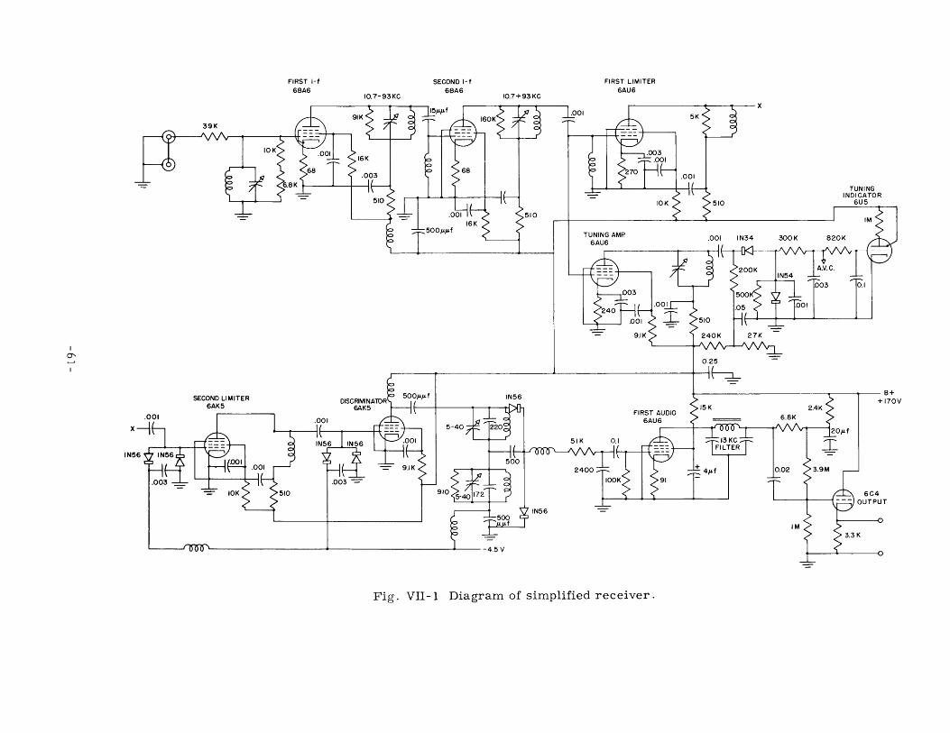
Fig. VII-1 Diagram of simplified receiver.
FIRST i-f
6BA6
39K
SECOND LIMITER6AK5
V
IN!