Embed Size (px)
Citation preview
ASIA FUELS & LUBES CONFERENCE(JAN. 25~28, 2000)
H.Y. Sung (SK Corporation)S.H. Kwon (SK Corporation)J.P. Andre (Raytheon E&C)
VHVI BASE OILS AND WHITE OILS FROM FUELS HYDROCRACKER
BOTTOMS
I . REFINERY OVERVIEW
II. UCO TECHNOLOGY
III. 1ST UPGRADING PROJECT
IV. 2ND UPGRADING PROJECT
V. SUMMARY
CONTENTS
3
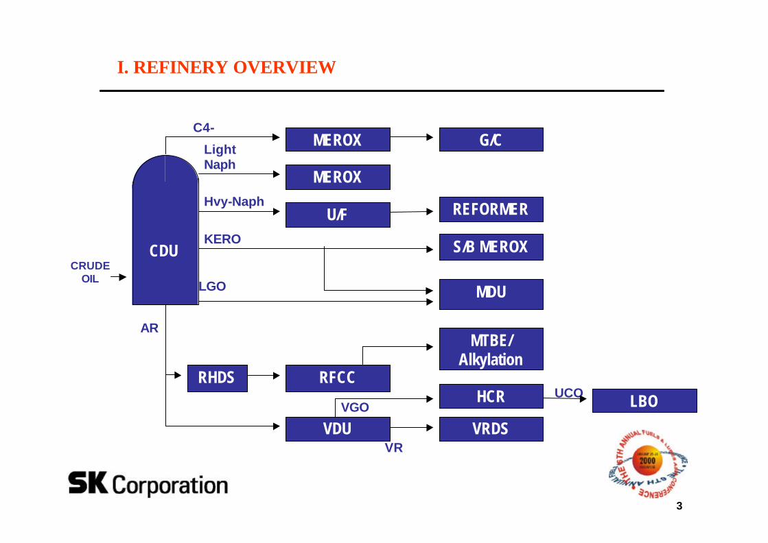
I. REFINERY OVERVIEW
G/CMEROX
MEROX
U/F REFORMER
S/B MEROX
MTBE/Alkylation
HCR
VRDS
MDU
RHDS
CRUDEOIL
CDU
C4-
LightNaph
Hvy-Naph
KERO
LGO
AR
VGOUCO
VDU
LBO
VR
RFCC
4
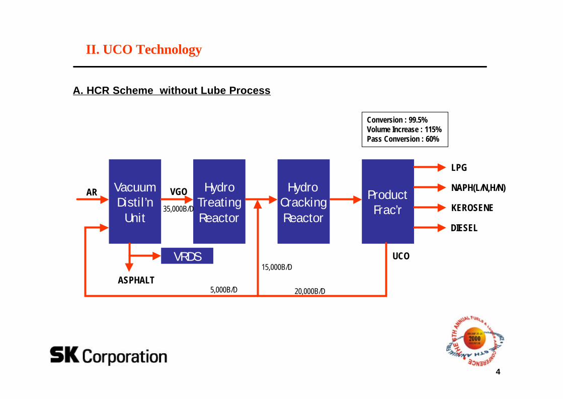
II. UCO Technology
A. HCR Scheme without Lube Process
Conversion : 99.5%Volume Increase : 115%Pass Conversion : 60%
VacuumDistil’n
Unit
HydroTreatingReactor
Hydro CrackingReactor
ProductFrac’r
AR VGO NAPH(L/N,H/N)
35,000B/D
20,000B/D5,000B/D
15,000B/DUCO
LPG
KEROSENE
DIESEL
VRDS
ASPHALT
5
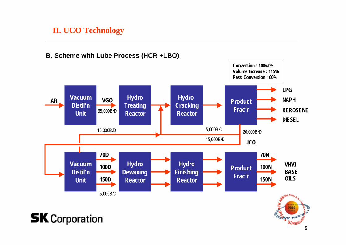
B. Scheme with Lube Process (HCR +LBO)Conversion : 100wt%Volume Increase : 115%Pass Conversion : 60%
VacuumDistil’n
Unit
HydroTreatingReactor
Hydro CrackingReactor
ProductFrac’r
AR VGO
KEROSENE35,000B/D
5,000B/D
UCO
VacuumDistil’n
Unit
HydroDewaxingReactor
HydroFinishingReactor
ProductFrac’r
20,000B/D
II. UCO Technology
10,000B/D
15,000B/D
70D
100D
150D
70N
100N
150N
LPG
DIESEL
NAPH
VHVIBASEOILS
5,000B/D
6
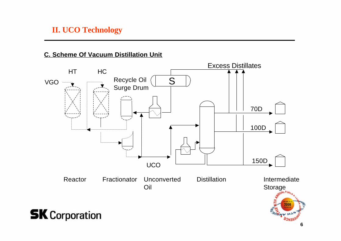
HT HC
Fractionator Distillation IntermediateStorage
Reactor UnconvertedOil
SRecycle OilSurge Drum
Excess Distillates
VGO
UCO
70D
100D
150D
C. Scheme Of Vacuum Distillation Unit
II. UCO Technology
7
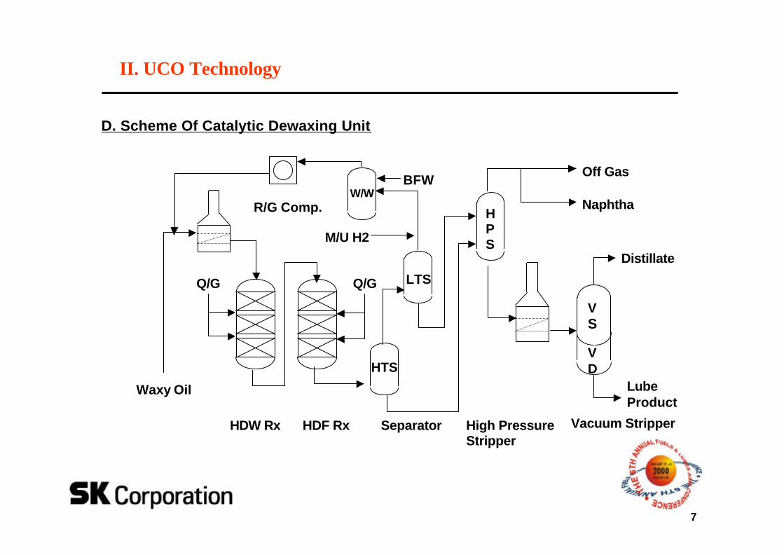
D. Scheme Of Catalytic Dewaxing Unit
II. UCO Technology
Waxy Oil
R/G Comp.W/W
LTS
HPS
HTS
Q/G Q/G
VS
VD
Off Gas
Naphtha
Distillate
LubeProduct
HDW Rx HDF Rx Separator High PressureStripper
Vacuum Stripper
BFW
M/U H2
8
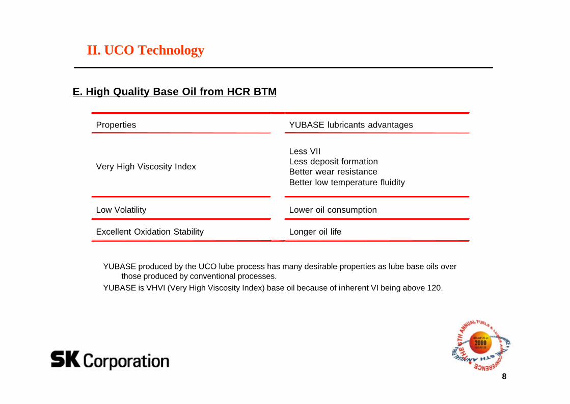
E. High Quality Base Oil from HCR BTM
YUBASE produced by the UCO lube process has many desirable properties as lube base oils over those produced by conventional processes.
YUBASE is VHVI (Very High Viscosity Index) base oil because of inherent VI being above 120.
Properties YUBASE lubricants advantages
Very High Viscosity Index
Less VIILess deposit formationBetter wear resistanceBetter low temperature fluidity
Low Volatility Lower oil consumption
Excellent Oxidation Stability Longer oil life
II. UCO Technology
9
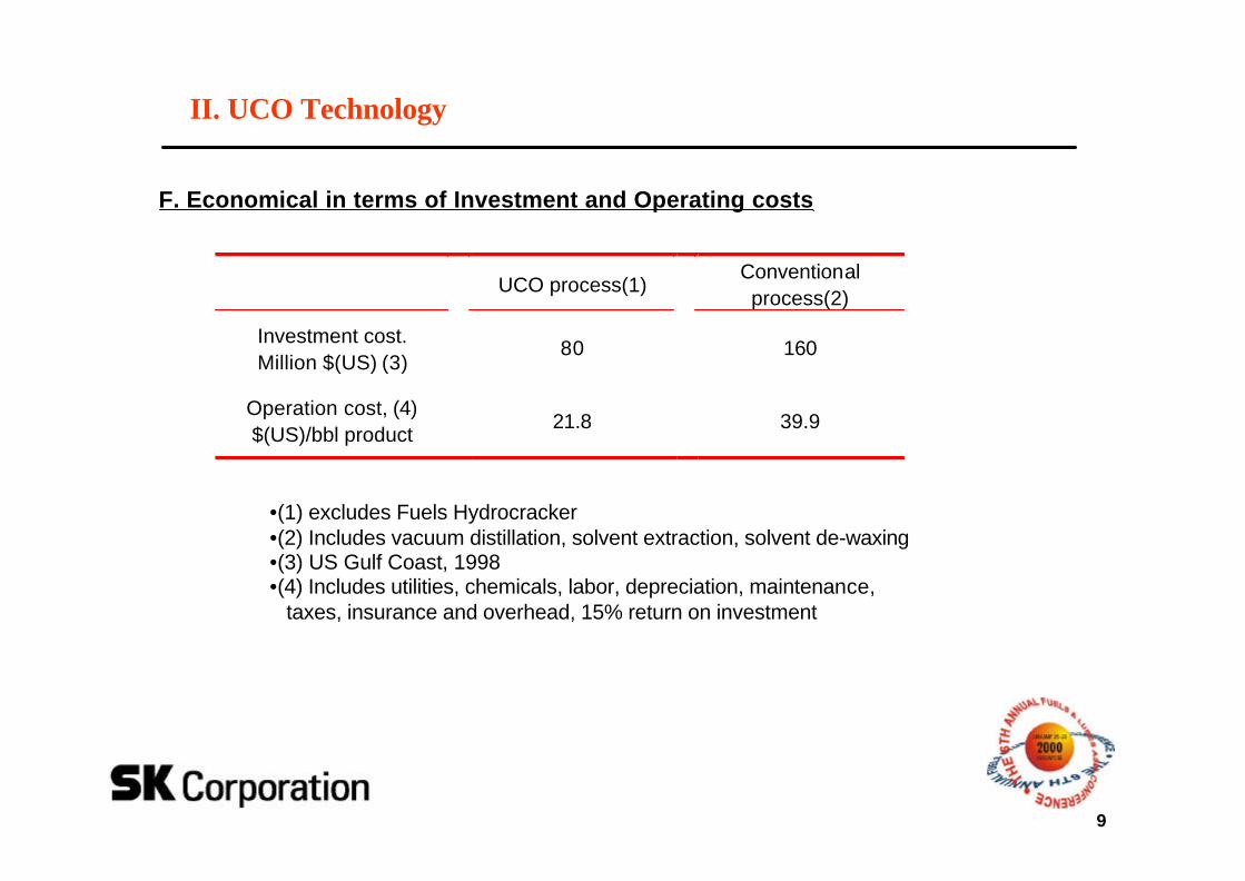
F. Economical in terms of Investment and Operating costs
II. UCO Technology
•(1) excludes Fuels Hydrocracker•(2) Includes vacuum distillation, solvent extraction, solvent de-waxing •(3) US Gulf Coast, 1998 •(4) Includes utilities, chemicals, labor, depreciation, maintenance,
taxes, insurance and overhead, 15% return on investment
UCO process(1)Conventionalprocess(2)
Investment cost.Million $(US) (3)
80 160
Operation cost, (4)$(US)/bbl product
21.8 39.9
10
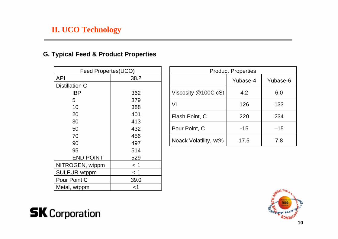
G. Typical Feed & Product Properties
II. UCO Technology
Feed Propertes(UCO)API 38.2Distillation C
IBP510203050709095END POINT
362379388401413432456497514529
NITROGEN, wtppm < 1SULFUR wtppm < 1Pour Point C 39.0Metal, wtppm <1
Product Properties
Yubase-4 Yubase-6
Viscosity @100C cSt 4.2 6.0
VI 126 133
Flash Point, C 220 234
Pour Point, C -15 –15
Noack Volatility, wt% 17.5 7.8
11
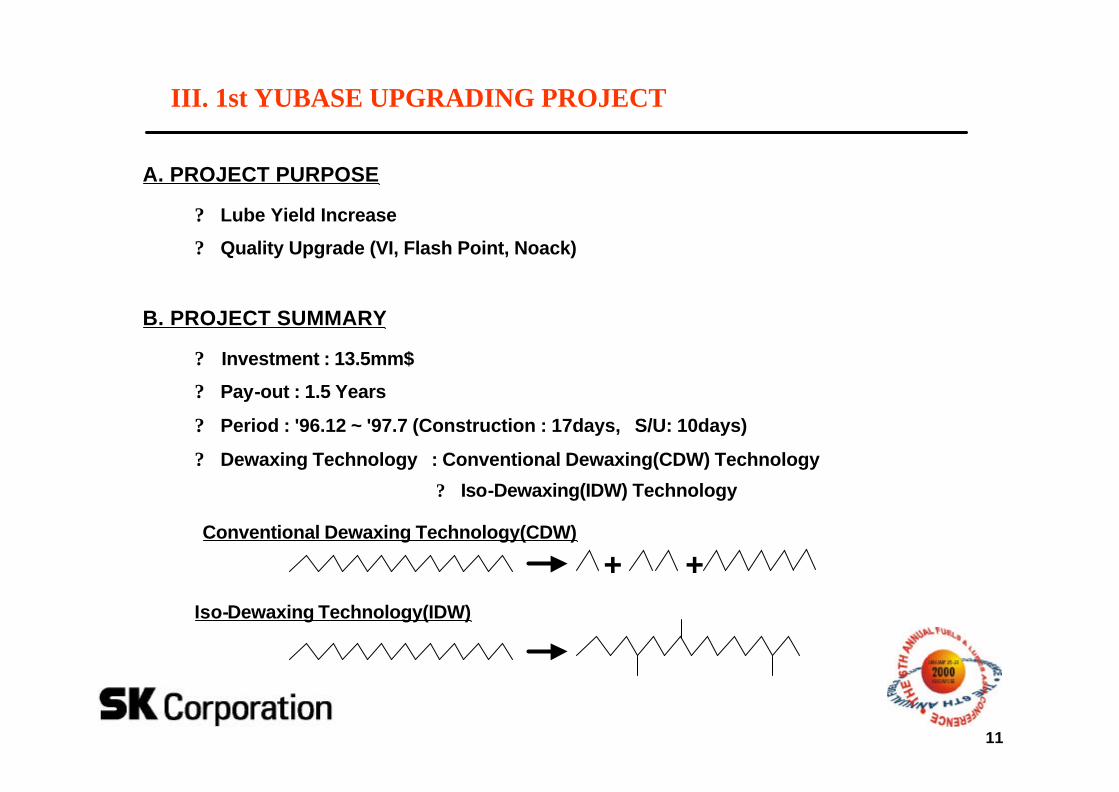
A. PROJECT PURPOSE
? Lube Yield Increase
? Quality Upgrade (VI, Flash Point, Noack)
Iso-Dewaxing Technology(IDW)
Conventional Dewaxing Technology(CDW)
+ +
III. 1st YUBASE UPGRADING PROJECT
B. PROJECT SUMMARY
? Investment : 13.5mm$
? Pay-out : 1.5 Years
? Period : '96.12 ~ '97.7 (Construction : 17days, S/U: 10days)
? Dewaxing Technology : Conventional Dewaxing(CDW) Technology
? Iso-Dewaxing(IDW) Technology
12
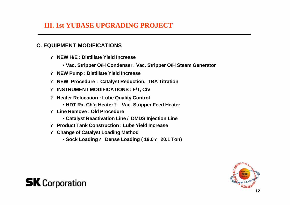
C. EQUIPMENT MODIFICATIONS
? NEW H/E : Distillate Yield Increase
•Vac. Stripper O/H Condenser, Vac. Stripper O/H Steam Generator
? NEW Pump : Distillate Yield Increase
? NEW Procedure : Catalyst Reduction, TBA Titration
? INSTRUMENT MODIFICATIONS : F/T, C/V
? Heater Relocation : Lube Quality Control•HDT Rx. Ch'g Heater ? Vac. Stripper Feed Heater
? Line Remove : Old Procedure•Catalyst Reactivation Line / DMDS Injection Line
? Product Tank Construction : Lube Yield Increase? Change of Catalyst Loading Method
•Sock Loading ? Dense Loading ( 19.0 ? 20.1 Ton)
III. 1st YUBASE UPGRADING PROJECT
13
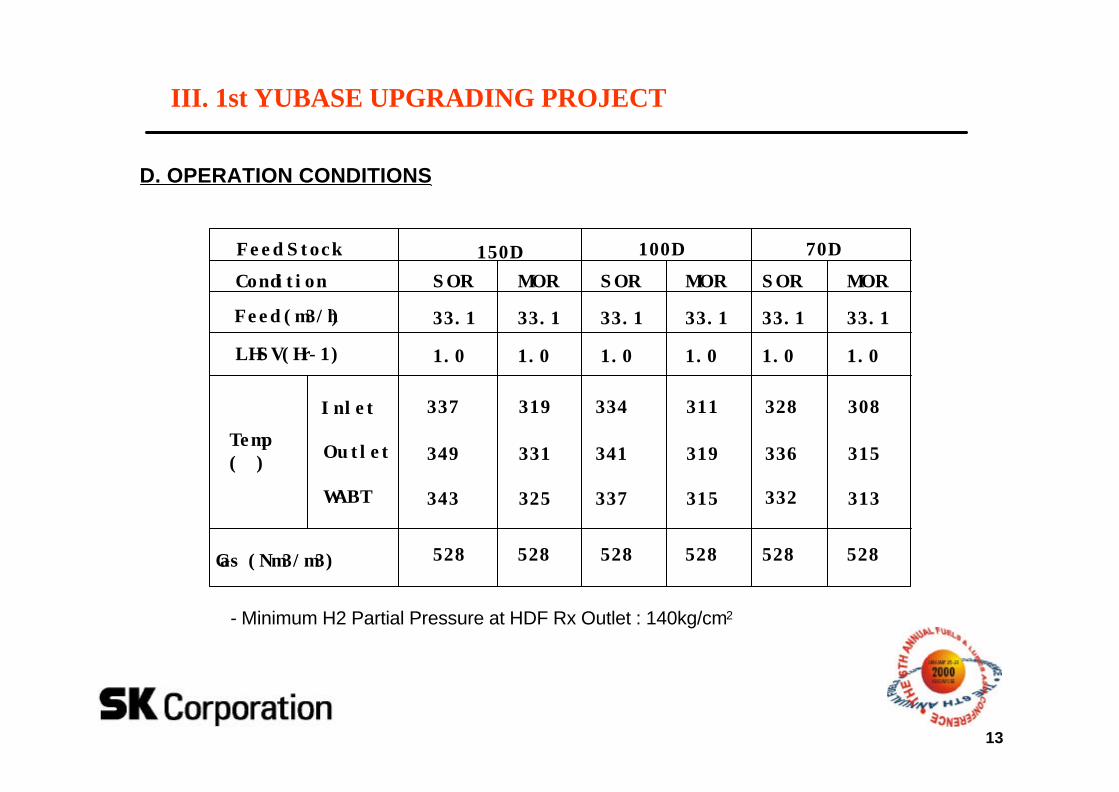
D. OPERATION CONDITIONS
III. 1st YUBASE UPGRADING PROJECT
Condition
Feed (m3/h)
LHSV(Hr-1)
Temp(℃)
Gas (Nm3/m3)
Feed Stock
SOR
33.1
1.0
528
150D 100D 70D
Inlet 337
Outlet 349
WABT 343
MOR
33.1
1.0
528
319
331
325
SOR
33.1
1.0
528
334
341
337
MOR
33.1
1.0
528
311
319
315
SOR
33.1
1.0
528
328
336
332
MOR
33.1
1.0
528
308
315
313
- Minimum H2 Partial Pressure at HDF Rx Outlet : 140kg/cm2
14
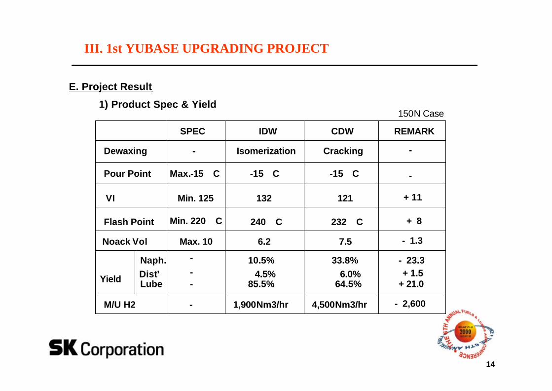
E. Project Result
IDW CDW
Dewaxing Isomerization Cracking
Pour Point -15°C -15°C
VI 132 121
Flash Point 240°C 232°C
Noack Vol 6.2 7.5
Yield
Naph. 10.5% 33.8%Dist’ 4.5% 6.0%Lube 85.5% 64.5%
SPEC
-
Max.-15°C
Min. 125
Min. 220°C
Max. 10
-
--
REMARK
-
-
+ 11
+ 8
- 1.3
- 23.3+ 1.5
+ 21.0
M/U H2 1,900Nm3/hr 4,500Nm3/hr- - 2,600
III. 1st YUBASE UPGRADING PROJECT
150N Case1) Product Spec & Yield
15
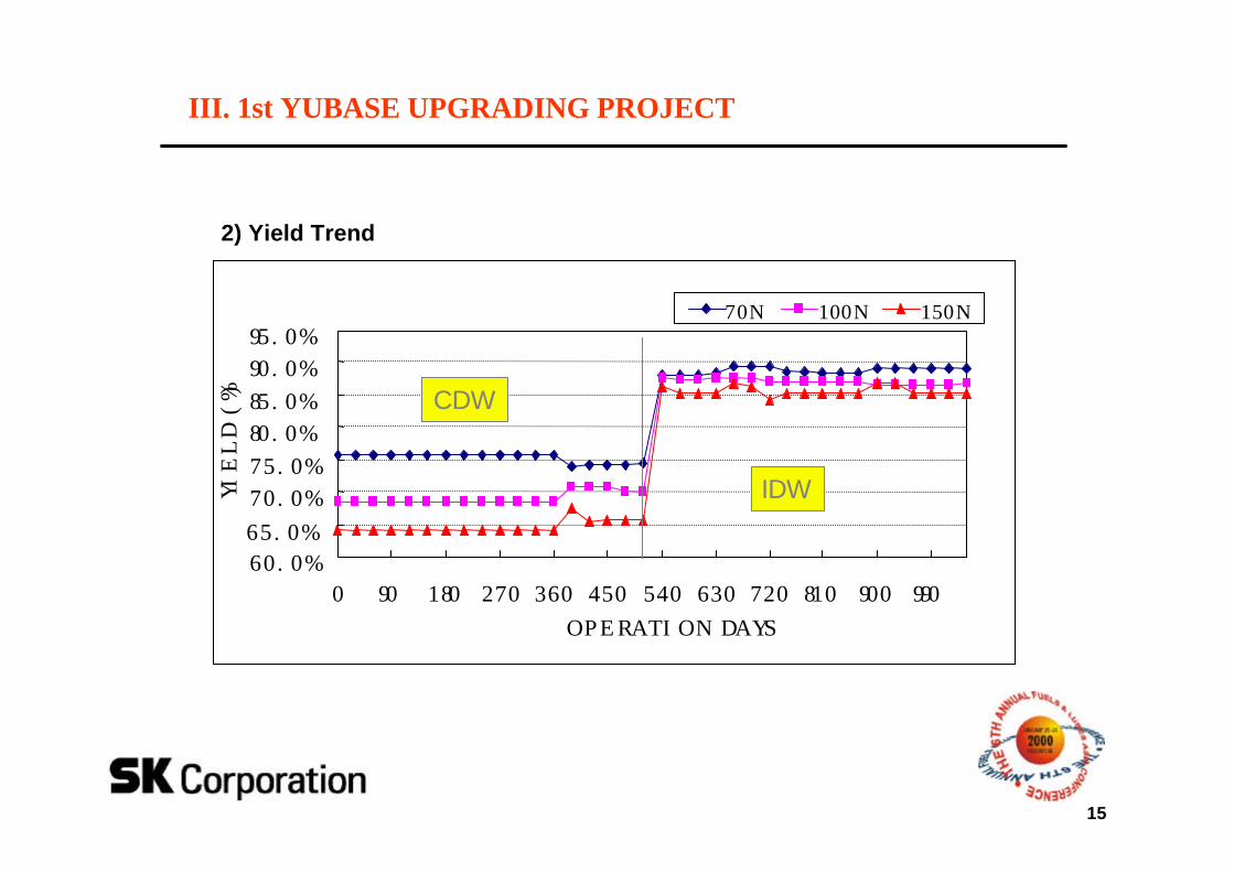
60.0%65.0%
70.0%75.0%
80.0%85.0%
90.0%95.0%
0 90 180 270 360 450 540 630 720 810 900 990
OPERATION DAYS
YIE
LD (
%)
70N 100N 150N
CDW
IDW
III. 1st YUBASE UPGRADING PROJECT
2) Yield Trend
16
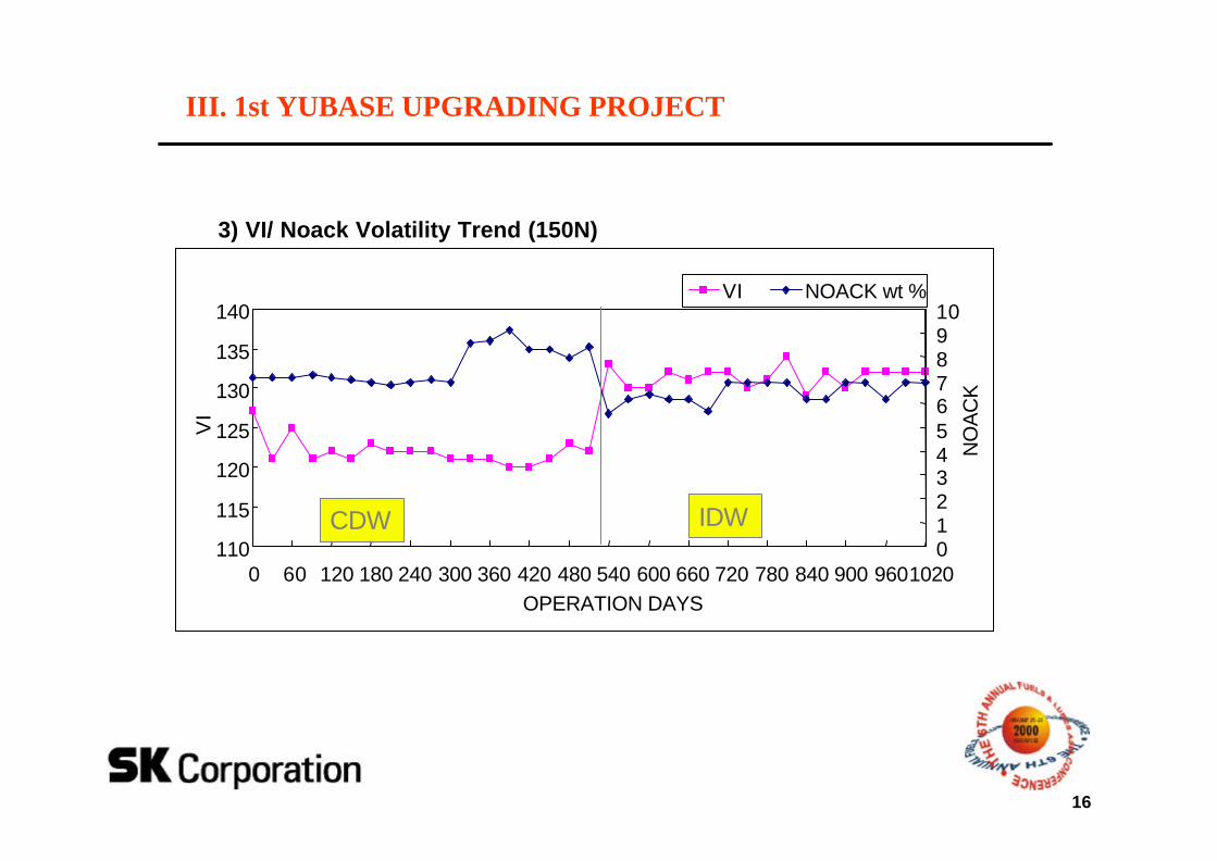
110
115
120
125
130
135
140
0 60 120 180 240 300 360 420 480 540 600 660 720 780 840 900 9601020OPERATION DAYS
VI
012345678910
NO
AC
K
VI NOACK wt %
CDW IDW
III. 1st YUBASE UPGRADING PROJECT
3) VI/ Noack Volatility Trend (150N)
17
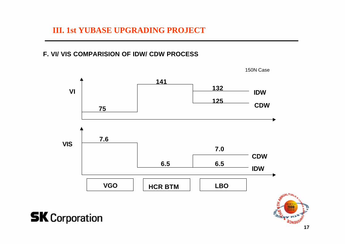
VGO HCR BTM LBO
VI
75
141132
125IDW
CDW
VIS7.6
6.5
7.0
6.5IDW
CDW
150N Case
III. 1st YUBASE UPGRADING PROJECT
F. VI/ VIS COMPARISION OF IDW/ CDW PROCESS
18
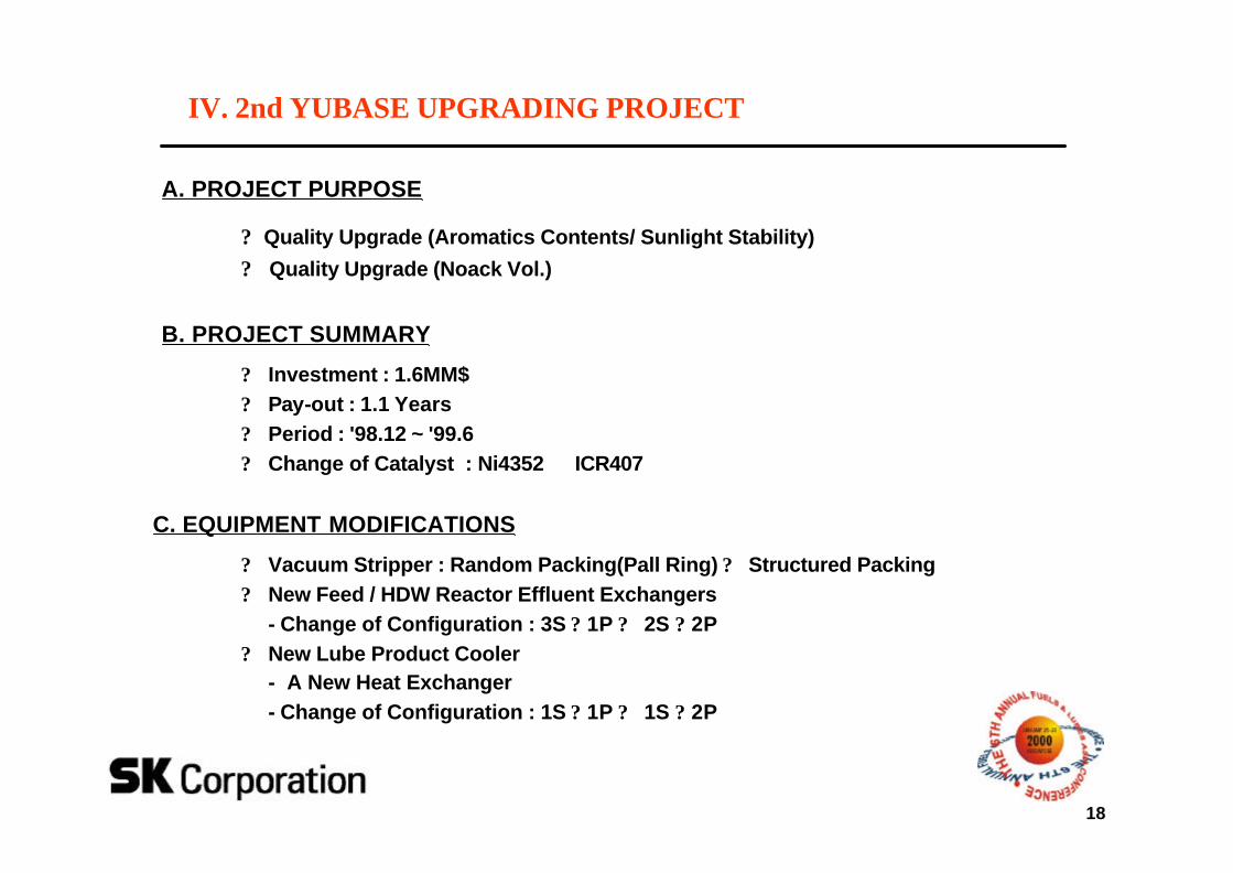
A. PROJECT PURPOSE
? Quality Upgrade (Aromatics Contents/ Sunlight Stability)
? Quality Upgrade (Noack Vol.)
B. PROJECT SUMMARY
? Investment : 1.6MM$? Pay-out : 1.1 Years? Period : '98.12 ~ '99.6? Change of Catalyst : Ni4352 → ICR407
C. EQUIPMENT MODIFICATIONS
? Vacuum Stripper : Random Packing(Pall Ring) ? Structured Packing? New Feed / HDW Reactor Effluent Exchangers
- Change of Configuration : 3S ? 1P ? 2S ? 2P? New Lube Product Cooler
- A New Heat Exchanger - Change of Configuration : 1S ? 1P ? 1S ? 2P
IV. 2nd YUBASE UPGRADING PROJECT
19
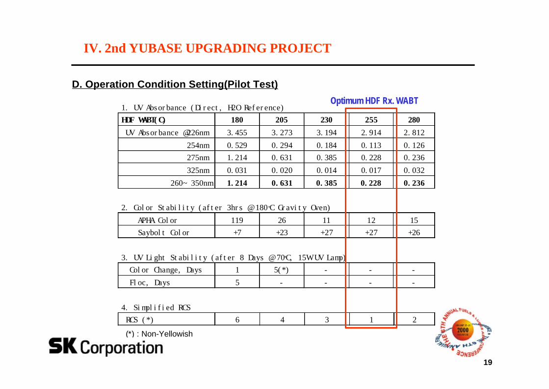
IV. 2nd YUBASE UPGRADING PROJECT
D. Operation Condition Setting(Pilot Test)
1. UV Absorbance (Direct, H2O Reference)
HDF WABT(C) 180 205 230 255 280
UV Absorbance @226nm 3.455 3.273 3.194 2.914 2.812
254nm 0.529 0.294 0.184 0.113 0.126
275nm 1.214 0.631 0.385 0.228 0.236
325nm 0.031 0.020 0.014 0.017 0.032
260~350nm 1.214 0.631 0.385 0.228 0.236
2. Color Stability (after 3hrs @ 180’C Gravity Oven)
APHA Color 119 26 11 12 15
Saybolt Color +7 +23 +27 +27 +26
3. UV Light Stability (after 8 Days @ 70’C, 15W UV Lamp) Color Change, Days 1 5(*) - - -
Floc, Days 5 - - - -
4. Simplified RCS
RCS (*) 6 4 3 1 2
(*) : Non-Yellowish
Optimum HDF Rx. WABT
20
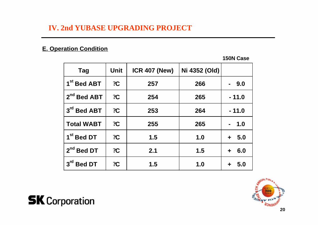
IV. 2nd YUBASE UPGRADING PROJECT
Tag Unit ICR 407 (New) Ni 4352 (Old)
1st Bed ABT ?C 257 266 - 9.0
2nd Bed ABT ?C 254 265 - 11.0
3rd Bed ABT ?C 253 264 - 11.0
Total WABT ?C 255 265 - 1.0
1st Bed DT ?C 1.5 1.0 + 5.0
2nd Bed DT ?C 2.1 1.5 + 6.0
3rd Bed DT ?C 1.5 1.0 + 5.0
150N Case
E. Operation Condition
21
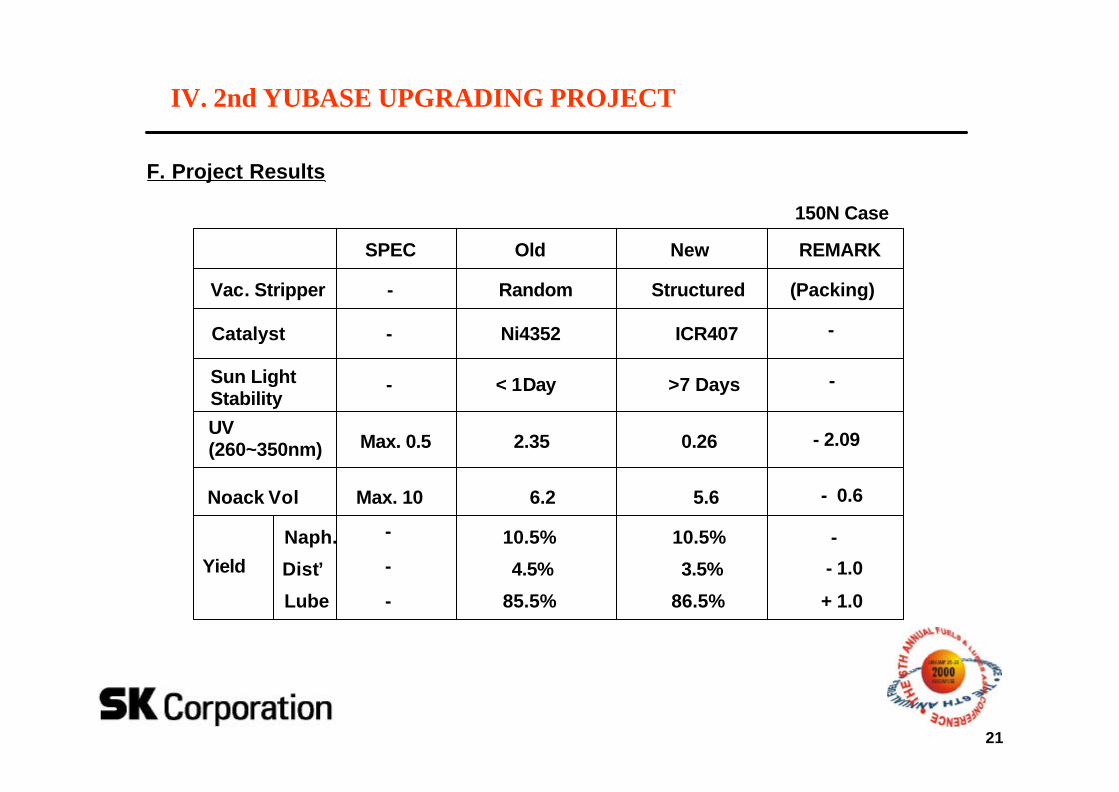
F. Project Results
Old New
Vac. Stripper Random Structured
Catalyst Ni4352 ICR407
Sun Light Stability
< 1Day >7 Days
UV(260~350nm) 2.35 0.26
Noack Vol 6.2 5.6
Yield
Naph. 10.5% 10.5%
Dist’ 4.5% 3.5%
Lube 85.5% 86.5%
SPEC
-
-
-
Max. 0.5
Max. 10
-
-
-
REMARK
(Packing)
-
-
- 2.09
- 0.6
-
- 1.0
+ 1.0
150N Case
IV. 2nd YUBASE UPGRADING PROJECT
22
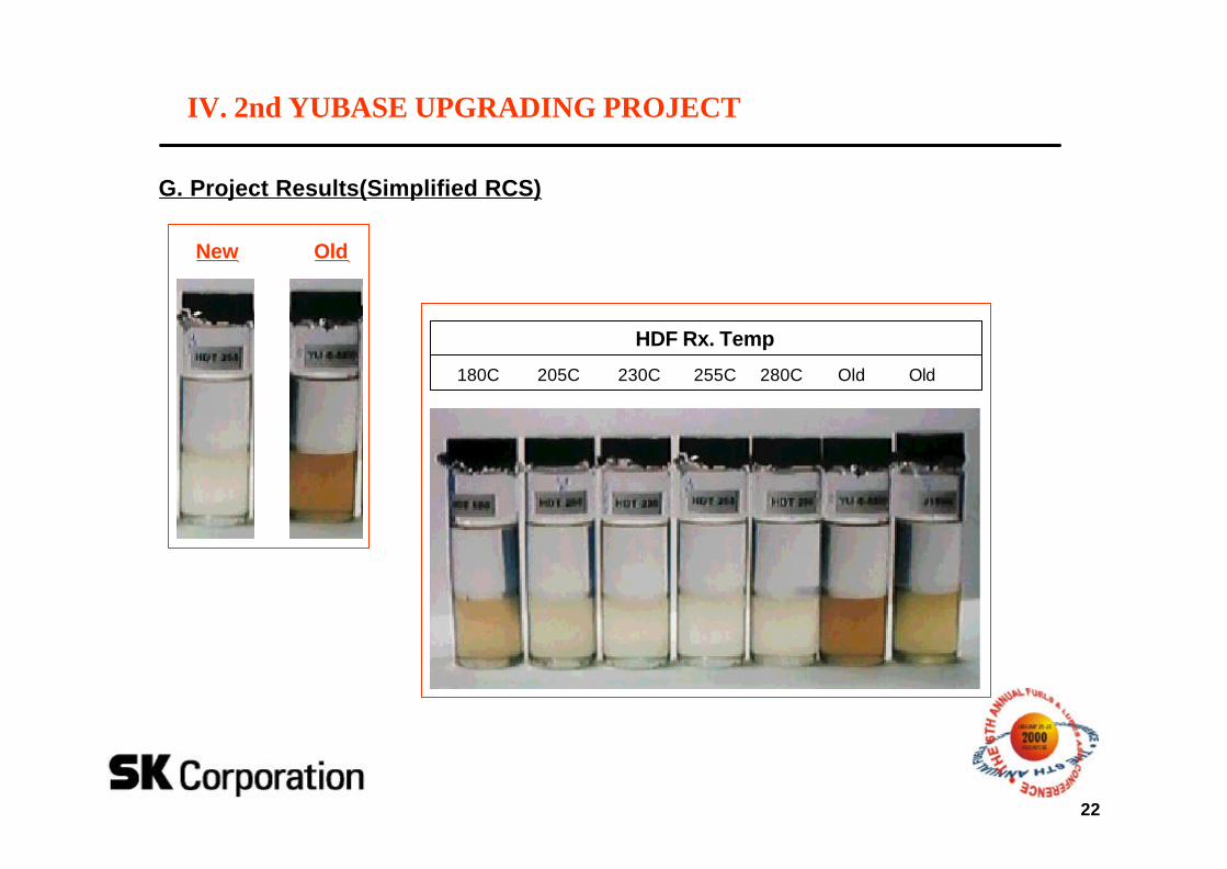
G. Project Results(Simplified RCS)
New Old
180C 205C 230C 255C 280C Old Old
IV. 2nd YUBASE UPGRADING PROJECT
HDF Rx. Temp
23
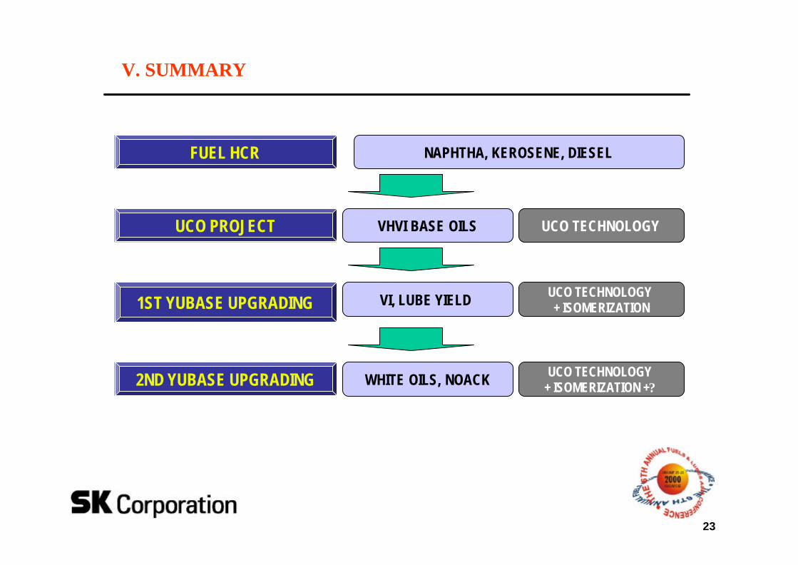
V. SUMMARY
FUEL HCR NAPHTHA, KEROSENE, DIESEL
UCO PROJECT VHVI BASE OILS
1ST YUBASE UPGRADING VI, LUBE YIELD
2ND YUBASE UPGRADING WHITE OILS, NOACK
UCO TECHNOLOGY
UCO TECHNOLOGY + ISOMERIZATION
UCO TECHNOLOGY + ISOMERIZATION +?


![Direct Catalytic Upgrading of Current Dilute Alcohol ... · Direct Catalytic Upgrading of Current Dilute Alcohol Fermentation Streams to Hydrocarbons for Fungible Fuels [2.3.1.100]](https://img.pdfslide.us/doc/110x75/600bd2071c10ee288c4907b3/direct-catalytic-upgrading-of-current-dilute-alcohol-direct-catalytic-upgrading.jpg)