Embed Size (px)
Citation preview
cui.com
date 06/16/2014
page 1 of 9
SERIES: VHK50W-DIN DESCRIPTION: DC-DC CONVERTER
date 06/16/2014
page 1 of 9
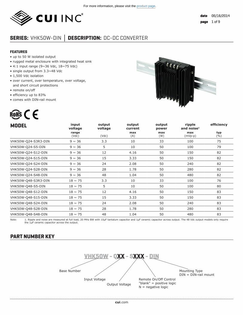
FEATURES• up to 50 W isolated output• rugged metal enclosure with integrated heat sink• 4:1 input range (9~36 Vdc, 18~75 Vdc)• single output from 3.3~48 Vdc• 1,500 Vdc isolation• over current, over temperature, over voltage, and short circuit protections• remote on/off• efficiency up to 83%• comes with DIN-rail mount
PART NUMBER KEY
MODEL inputvoltage
outputvoltage
outputcurrent
outputpower
ripple and noise1
efficiency
range(Vdc) (Vdc)
max(A)
max(W)
max(mVp-p)
typ(%)
VHK50W-Q24-S3R3-DIN 9 ~ 36 3.3 10 33 100 75
VHK50W-Q24-S5-DIN 9 ~ 36 5 10 50 100 79
VHK50W-Q24-S12-DIN 9 ~ 36 12 4.16 50 150 82
VHK50W-Q24-S15-DIN 9 ~ 36 15 3.33 50 150 82
VHK50W-Q24-S24-DIN 9 ~ 36 24 2.08 50 240 82
VHK50W-Q24-S28-DIN 9 ~ 36 28 1.78 50 280 82
VHK50W-Q24-S48-DIN 9 ~ 36 48 1.04 50 480 82
VHK50W-Q48-S3R3-DIN 18 ~ 75 3.3 10 33 100 76
VHK50W-Q48-S5-DIN 18 ~ 75 5 10 50 100 80
VHK50W-Q48-S12-DIN 18 ~ 75 12 4.16 50 150 83
VHK50W-Q48-S15-DIN 18 ~ 75 15 3.33 50 150 83
VHK50W-Q48-S24-DIN 18 ~ 75 24 2.08 50 240 83
VHK50W-Q48-S28-DIN 18 ~ 75 28 1.78 50 280 83
VHK50W-Q48-S48-DIN 18 ~ 75 48 1.04 50 480 83Note: 1. Ripple and noise are measured at full load, 20 MHz BW with 10µF tantalum capacitor and 1µF ceramic capacitor across output. The 48 Vdc output models only require the 1µF ceramic capacitor across the output.
VHK50W - QXX - SXXX - DIN
Input VoltageOutput Voltage
Base Number Mounting TypeDIN = DIN-rail mount
Remote On/Off Control"blank" = positive logicN = negative logic
For more information, please visit the product page.
cui.com
CUI Inc SERIES: VHK50W-DIN DESCRIPTION: DC-DC CONVERTER date 06/16/2014 page 2 of 9
INPUTparameter conditions/description min typ max units
operating input voltage 24 Vdc input models48 Vdc input models
918
2448
3675
VdcVdc
under voltage shutdown24 Vdc input power up
power down8.88
VdcVdc
48 Vdc input power uppower down
1716
VdcVdc
CTRL1
positive logicmodels ON (open circuit)
models OFF (0~0.8 Vdc)
negative logicmodels ON (0~0.8 Vdc)
models OFF (open circuit)
filter pi filter
input fuse 15A time delay fuse for 24 Vin models,8A time delay fuse for 48 Vin models
Note: 1. Open collector refer to -Vin
OUTPUTparameter conditions/description min typ max units
maximum capacitive load
3.3 and 5 V output models12 V output models15 V output models24 V output models28 V output models48 V output models 47
10,0004,1603,3302,0801,7801,040
μFμFμFμFμFμF
line regulation2 measured from high line to low line ±0.2 %
load regulation2 measured from full load to zero load ±0.2 %
voltage accuracy2 ±1 %
adjustability ±10 %
switching frequency 300 kHz
transient response 25% step load change 500 µs
temperature coefficient ±0.03 %/°CNote: 2. A 47 μF aluminum capacitor is required on the output for 48 Vdc output models.
PROTECTIONSparameter conditions/description min typ max units
short circuit protection continuous
over current protection % nominal output current 110 160 %
over voltage protection 115 140 %
over temperature protection shutdownrestart threshold
10070
°C°C
SAFETY AND COMPLIANCEparameter conditions/description min typ max units
isolation voltage for 1 min: input/output; input/case; output/case 1,500 Vdc
isolation resistance 10 MΩ
RoHS 2011/65/EU (CE)
ENVIRONMENTALparameter conditions/description min typ max units
operating temperature see derating curve -40 85 °C
storage temperature -55 105 °C
For more information, please visit the product page.
cui.com
CUI Inc SERIES: VHK50W-DIN DESCRIPTION: DC-DC CONVERTER date 06/16/2014 page 3 of 9
38.0
1.50
0.57
14.6
35.01.38
0.50
12.8
2 - DIN RAIL CLIP
OUTPUTINPUT
0.75
1.18
30.0
30.0
1.18
19.01.91 48.5
Top View
Side View
Bottom View
Back ViewFront View
52.6
2.07
4
1 5
9
1.8
92.0
17.0
4.01
101.
8
4.09 104.0
4.5
3.62
4.23 107.5
0.18
0.070.67 2.76 70.0
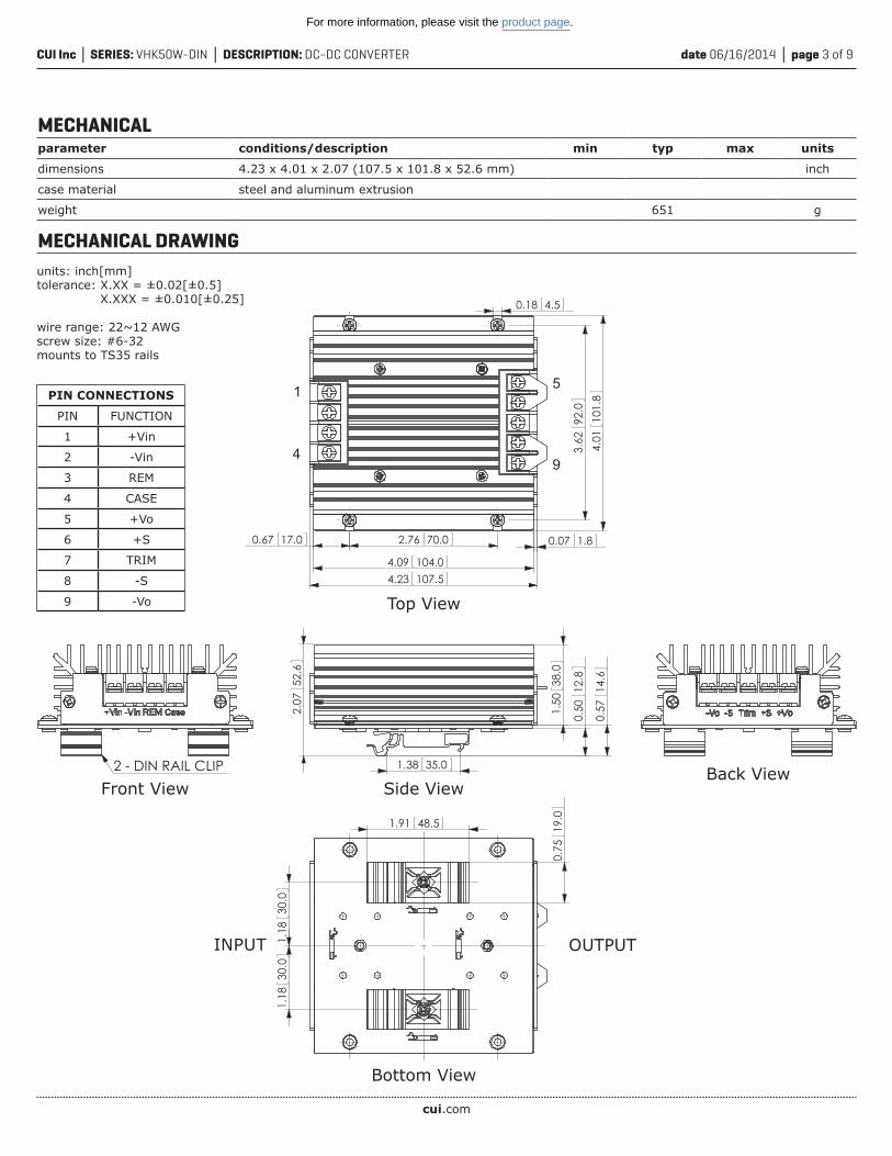
MECHANICALparameter conditions/description min typ max units
dimensions 4.23 x 4.01 x 2.07 (107.5 x 101.8 x 52.6 mm) inch
case material steel and aluminum extrusion
weight 651 g
MECHANICAL DRAWING
PIN CONNECTIONS
PIN FUNCTION
1 +Vin
2 -Vin
3 REM
4 CASE
5 +Vo
6 +S
7 TRIM
8 -S
9 -Vo
units: inch[mm]tolerance: X.XX = ±0.02[±0.5] X.XXX = ±0.010[±0.25]
wire range: 22~12 AWGscrew size: #6-32mounts to TS35 rails
For more information, please visit the product page.
cui.com
CUI Inc SERIES: VHK50W-DIN DESCRIPTION: DC-DC CONVERTER date 06/16/2014 page 4 of 9
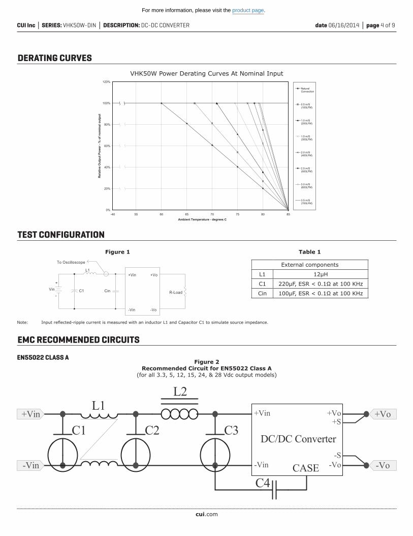
DERATING CURVES
0%
20%
40%
60%
80%
100%
120%
-40 55 60 65 70 75 80 85
Ambient Temperature - degrees C
Rel
ativ
e O
utpu
t Pow
er -
% o
f nom
inal
out
put
NaturalConvection
0.5 m/S(100LFM)
1.0 m/S(200LFM)
1.5 m/S(300LFM)
2.0 m/S(400LFM)
2.5 m/S(500LFM)
3.0 m/S(600LFM)
3.5 m/S(700LFM)
VHK50W Power Derating Curves At Nominal Input
EMC RECOMMENDED CIRCUITS
Figure 1
Figure 2Recommended Circuit for EN55022 Class A
(for all 3.3, 5, 12, 15, 24, & 28 Vdc output models)
EN55022 CLASS A
Table 1
TEST CONFIGURATION
C1 Cin
L1
To Oscilloscope
+Vin
-Vin
+Vo
-Vo
R-LoadVin
+
-
Note: Input reflected-ripple current is measured with an inductor L1 and Capacitor C1 to simulate source impedance.
External components
L1 12μH
C1 220μF, ESR < 0.1Ω at 100 KHz
Cin 100μF, ESR < 0.1Ω at 100 KHz
C4
DC/DC Converter
CASE
+Vo
-Vo
+Vin
C1
-Vin
L2
C3C2
L1+Vo
-Vo
+Vin
-Vin-S
+S
For more information, please visit the product page.
cui.com
CUI Inc SERIES: VHK50W-DIN DESCRIPTION: DC-DC CONVERTER date 06/16/2014 page 5 of 9
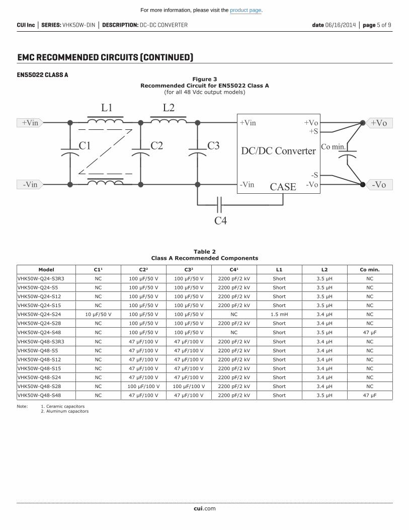
EMC RECOMMENDED CIRCUITS (CONTINUED)
Figure 3Recommended Circuit for EN55022 Class A
(for all 48 Vdc output models)
Table 2Class A Recommended Components
C3
L2L1+Vin +Vin
-Vin -Vin
+Vo
-Vo-S
+S
CASE
DC/DC ConverterC2
C4
C1 Co min.
+Vo
-Vo
Model C11 C22 C32 C41 L1 L2 Co min.
VHK50W-Q24-S3R3 NC 100 μF/50 V 100 μF/50 V 2200 pF/2 kV Short 3.5 μH NC
VHK50W-Q24-S5 NC 100 μF/50 V 100 μF/50 V 2200 pF/2 kV Short 3.5 μH NC
VHK50W-Q24-S12 NC 100 μF/50 V 100 μF/50 V 2200 pF/2 kV Short 3.5 μH NC
VHK50W-Q24-S15 NC 100 μF/50 V 100 μF/50 V 2200 pF/2 kV Short 3.5 μH NC
VHK50W-Q24-S24 10 μF/50 V 100 μF/50 V 100 μF/50 V NC 1.5 mH 3.4 μH NC
VHK50W-Q24-S28 NC 100 μF/50 V 100 μF/50 V 2200 pF/2 kV Short 3.4 μH NC
VHK50W-Q24-S48 NC 100 μF/50 V 100 μF/50 V NC Short 3.5 μH 47 μF
VHK50W-Q48-S3R3 NC 47 μF/100 V 47 μF/100 V 2200 pF/2 kV Short 3.4 μH NC
VHK50W-Q48-S5 NC 47 μF/100 V 47 μF/100 V 2200 pF/2 kV Short 3.4 μH NC
VHK50W-Q48-S12 NC 47 μF/100 V 47 μF/100 V 2200 pF/2 kV Short 3.4 μH NC
VHK50W-Q48-S15 NC 47 μF/100 V 47 μF/100 V 2200 pF/2 kV Short 3.4 μH NC
VHK50W-Q48-S24 NC 47 μF/100 V 47 μF/100 V 2200 pF/2 kV Short 3.4 μH NC
VHK50W-Q48-S28 NC 100 μF/100 V 100 μF/100 V 2200 pF/2 kV Short 3.4 μH NC
VHK50W-Q48-S48 NC 47 μF/100 V 47 μF/100 V 2200 pF/2 kV Short 3.5 μH 47 μF
Note: 1. Ceramic capacitors 2. Aluminum capacitors
EN55022 CLASS A
For more information, please visit the product page.
cui.com
CUI Inc SERIES: VHK50W-DIN DESCRIPTION: DC-DC CONVERTER date 06/16/2014 page 6 of 9
C3
L2L1+Vin +Vin
-Vin -Vin
+Vo
-VoCASE
DC/DC ConverterC2
C5
C1
+Vo
-Vo
-S
+S
C3
L2
C6
L1+Vin +Vin
-Vin -Vin
+Vo
-Vo-S
+S
CASE
DC/DC ConverterC2
C4 C5
C1 Co min.
+Vo
-Vo
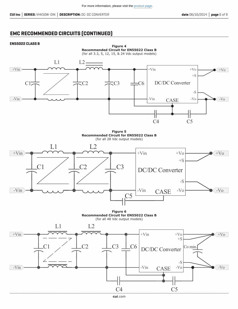
Figure 5Recommended Circuit for EN55022 Class B
(for all 28 Vdc output models)
Figure 6Recommended Circuit for EN55022 Class B
(for all 48 Vdc output models)
EMC RECOMMENDED CIRCUITS (CONTINUED)
Figure 4Recommended Circuit for EN55022 Class B(for all 3.3, 5, 12, 15, & 24 Vdc output models)
EN55022 CLASS B
L2
C6C1
L1+Vin
-Vin
+Vo
-VoCASE
C2 C3
C4 C5
+Vin
-Vin
+Vo
-Vo
-S
+S
DC/DC Converter
For more information, please visit the product page.
cui.com
CUI Inc SERIES: VHK50W-DIN DESCRIPTION: DC-DC CONVERTER date 06/16/2014 page 7 of 9
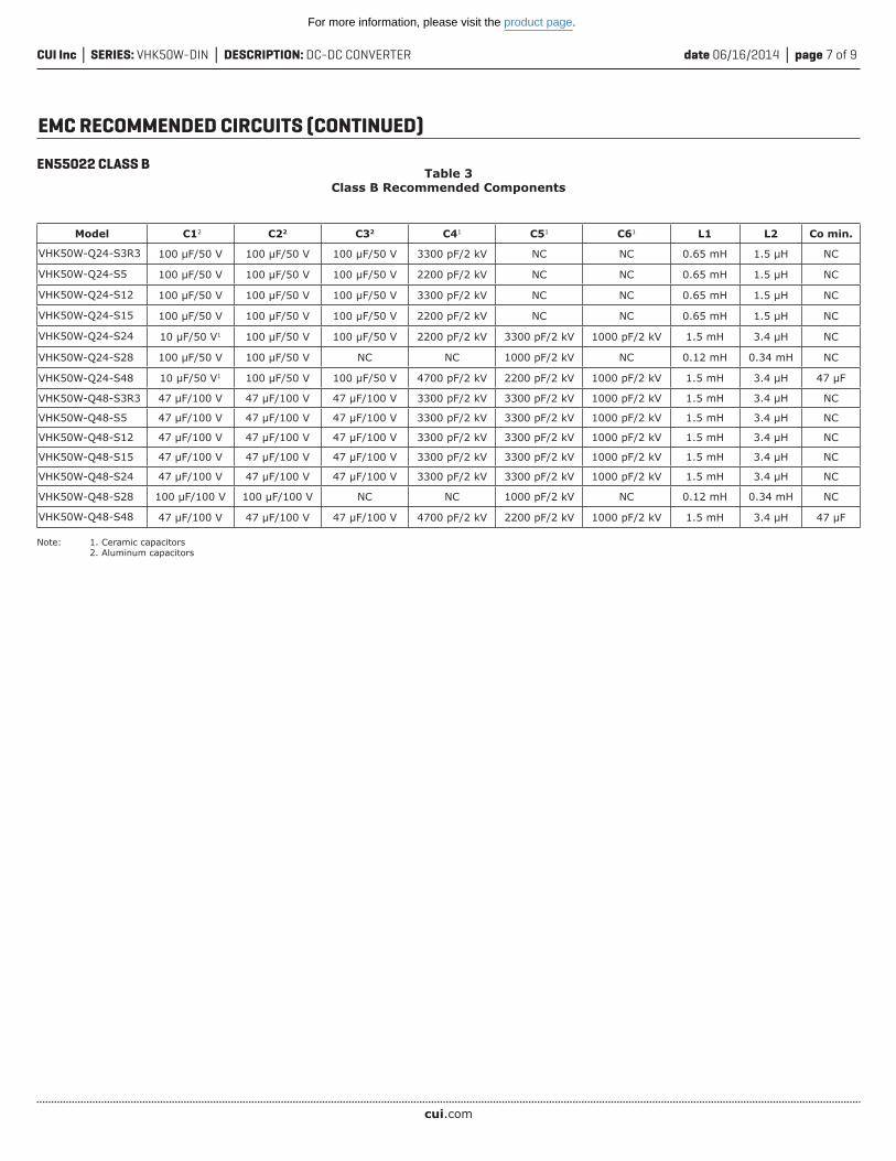
EMC RECOMMENDED CIRCUITS (CONTINUED)
Table 3Class B Recommended Components
Model C12 C22 C32 C41 C51 C61 L1 L2 Co min.
VHK50W-Q24-S3R3 100 μF/50 V 100 μF/50 V 100 μF/50 V 3300 pF/2 kV NC NC 0.65 mH 1.5 μH NC
VHK50W-Q24-S5 100 μF/50 V 100 μF/50 V 100 μF/50 V 2200 pF/2 kV NC NC 0.65 mH 1.5 μH NC
VHK50W-Q24-S12 100 μF/50 V 100 μF/50 V 100 μF/50 V 3300 pF/2 kV NC NC 0.65 mH 1.5 μH NC
VHK50W-Q24-S15 100 μF/50 V 100 μF/50 V 100 μF/50 V 2200 pF/2 kV NC NC 0.65 mH 1.5 μH NC
VHK50W-Q24-S24 10 μF/50 V1 100 μF/50 V 100 μF/50 V 2200 pF/2 kV 3300 pF/2 kV 1000 pF/2 kV 1.5 mH 3.4 μH NC
VHK50W-Q24-S28 100 μF/50 V 100 μF/50 V NC NC 1000 pF/2 kV NC 0.12 mH 0.34 mH NC
VHK50W-Q24-S48 10 μF/50 V1 100 μF/50 V 100 μF/50 V 4700 pF/2 kV 2200 pF/2 kV 1000 pF/2 kV 1.5 mH 3.4 μH 47 μF
VHK50W-Q48-S3R3 47 μF/100 V 47 μF/100 V 47 μF/100 V 3300 pF/2 kV 3300 pF/2 kV 1000 pF/2 kV 1.5 mH 3.4 μH NC
VHK50W-Q48-S5 47 μF/100 V 47 μF/100 V 47 μF/100 V 3300 pF/2 kV 3300 pF/2 kV 1000 pF/2 kV 1.5 mH 3.4 μH NC
VHK50W-Q48-S12 47 μF/100 V 47 μF/100 V 47 μF/100 V 3300 pF/2 kV 3300 pF/2 kV 1000 pF/2 kV 1.5 mH 3.4 μH NC
VHK50W-Q48-S15 47 μF/100 V 47 μF/100 V 47 μF/100 V 3300 pF/2 kV 3300 pF/2 kV 1000 pF/2 kV 1.5 mH 3.4 μH NC
VHK50W-Q48-S24 47 μF/100 V 47 μF/100 V 47 μF/100 V 3300 pF/2 kV 3300 pF/2 kV 1000 pF/2 kV 1.5 mH 3.4 μH NC
VHK50W-Q48-S28 100 μF/100 V 100 μF/100 V NC NC 1000 pF/2 kV NC 0.12 mH 0.34 mH NC
VHK50W-Q48-S48 47 μF/100 V 47 μF/100 V 47 μF/100 V 4700 pF/2 kV 2200 pF/2 kV 1000 pF/2 kV 1.5 mH 3.4 μH 47 μF
Note: 1. Ceramic capacitors 2. Aluminum capacitors
EN55022 CLASS B
For more information, please visit the product page.
cui.com
CUI Inc SERIES: VHK50W-DIN DESCRIPTION: DC-DC CONVERTER date 06/16/2014 page 8 of 9
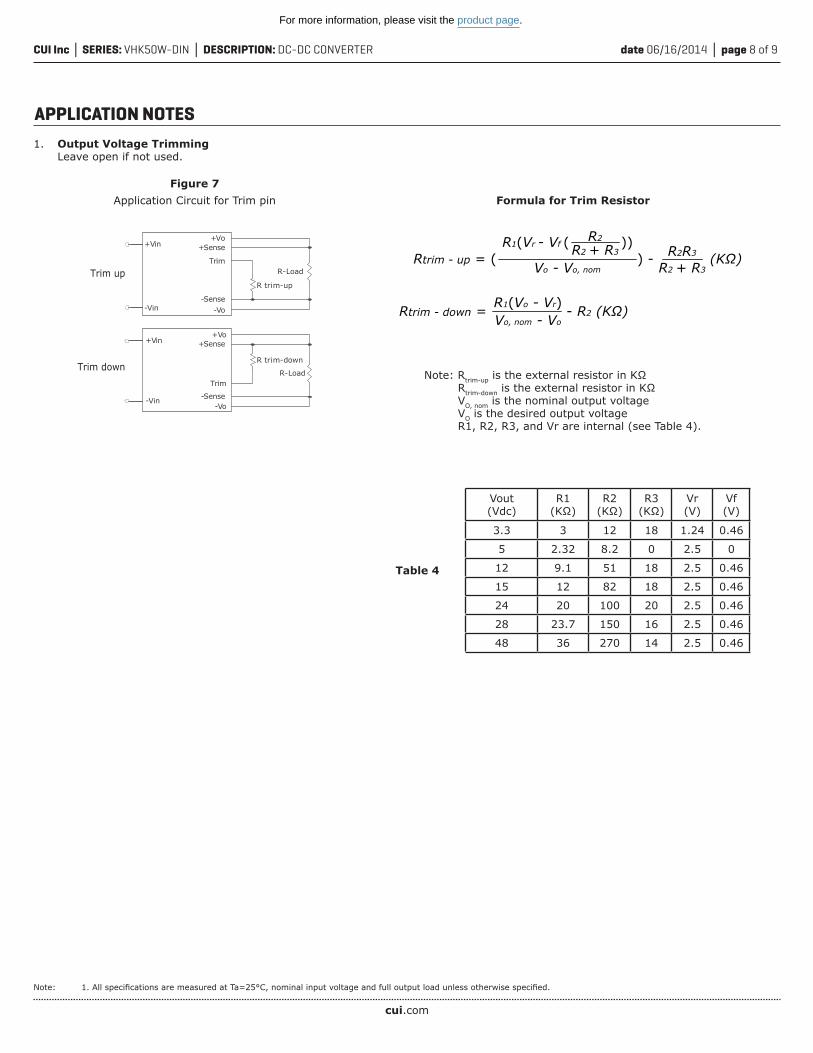
APPLICATION NOTES1. Output Voltage Trimming
Leave open if not used.
+Vin
R trim-up
R-LoadTrim
+Vo+Sense
+Sense
-Sense
-Sense
-Vin -Vo
Trim up
+Vin
-Vin-Vo
+Vo
R trim-down
R-LoadTrim
Trim down
Figure 7Application Circuit for Trim pin
Note: 1. All specifications are measured at Ta=25°C, nominal input voltage and full output load unless otherwise specified.
Table 4
Vout(Vdc)
R1(KΩ)
R2(KΩ)
R3(KΩ)
Vr(V)
Vf(V)
3.3 3 12 18 1.24 0.46
5 2.32 8.2 0 2.5 0
12 9.1 51 18 2.5 0.46
15 12 82 18 2.5 0.46
24 20 100 20 2.5 0.46
28 23.7 150 16 2.5 0.46
48 36 270 14 2.5 0.46
R1(Vr - Vf ( ))Rtrim - up = ( ) - (KΩ)
Rtrim - down = - R2 (KΩ)
Vo - Vo, nom
R2
R2 + R3
R2 + R3
R2R3
R1(Vo - Vr)Vo, nom - Vo
Note: Rtrim-up is the external resistor in KΩ Rtrim-down is the external resistor in KΩ VO, nom is the nominal output voltage VO is the desired output voltage R1, R2, R3, and Vr are internal (see Table 4).
Formula for Trim Resistor
For more information, please visit the product page.
CUI Inc SERIES: VHK50W-DIN DESCRIPTION: DC-DC CONVERTER date 06/16/2014 page 9 of 9
CUI offers a two (2) year limited warranty. Complete warranty information is listed on our website.
CUI reserves the right to make changes to the product at any time without notice. Information provided by CUI is believed to be accurate and reliable. However, no responsibility is assumed by CUI for its use, nor for any infringements of patents or other rights of third parties which may result from its use.
CUI products are not authorized or warranted for use as critical components in equipment that requires an extremely high level of reliability. A critical component is any component of a life support device or system whose failure to perform can be reasonably expected to cause the failure of the life support device or system, or to affect its safety or effectiveness.
Headquarters20050 SW 112th Ave.Tualatin, OR 97062800.275.4899
rev. description date
1.0 initial release 12/17/20131.01 changed DIN-rail mount 06/16/2014
The revision history provided is for informational purposes only and is believed to be accurate.
REVISION HISTORY
For more information, please visit the product page.