Embed Size (px)
Citation preview

VHF DSC S15 CLASSE D DSC, NAVTEX, GPS
Operation Manual S15
Page 1
Chapter Description Page 1 Introduction 3 2 Front Panel Description 4
2.1 Front 42.2 Back Of Unit 52.3 LCD Display 6
3 Fist Microphone/Controller 7 3.1 Soft Keypad (0 – 9) 7
4 General Operation 9 4.1 Dual Watch 94.2 Full Scan 104.3 Memory Scan 104.4 High / Low RF Output Power Selection 104.5 Squelch Control 114.6 Volume Control 114.7 Channel 16 124.8 Channel Select 124.9 Memory Channel Select 12
5 Receiving A DSC Call 13 5.1 Routine Calls 135.2 Urgency And Safety Calls 135.3 Group Calls 145.4 Distress Alert 14
6 Sending A DSC Call 16 6.1 Distress Calls 166.2 Routine Calls 176.3 Urgency And Safety Calls 186.4 Group Calls 19
7 Log View 20 7.1 Review Routine Log 207.2 Review Distress Log 217.3 View NAVTEX Messages 22
Operation Manual S15
Page 2
8 Settings 24
8.1 Backlight & Keypad Lighting Adjustment 248.2 Contrast Adjustment 248.3 Speaker Selection 258.4 Tone Selection 25
9 DSC Setting 26 9.1 MMSI Setting 269.2 Set Group ID 279.3 Set Date And Time 289.4 Set Manual Position 289.5 Set Called Channels 299.6 Set Directory Of Called MMSI And Vessel Names 31
10 NAVTEX Setting 33 10.1 Station Selection 3310.2 Message Selection 3410.3 Clear All NAVTEX Logs 34
11 GPS Navigation Setting 36 11.1 Set Waypoint Number (Go To Waypoint) 3611.2 Set Waypoint 3711.3 Review Waypoint 3811.4 Navigation View 3811.5 Insert Waypoint 4011.6 Delete Waypoint 41
12 Technical Specifications 42 12.1 Receiver 4212.2 Channel 70 Monitor General Specification 4312.3 Transmitter 4312.4 NAVTEX 4312.5 GPS 43
13 VHF Marine Channel Chart 44 14 Installation 45
14.1 Unit Installation 4514.2 Antenna Installation Recommendations 46
15 Parts Provided 48 16 Warranty 48 17 Certificate Of Conformity 49
Operation Manual S15
Page 3
1. Introduction The S15 is a Class-D Digital Selective Calling (DSC) VHF marine transceiver with built in GPS capability (position, waypoints, course and speed over the ground) if connected with GPS input from either a GPS navigator or smart antenna. The S15 also has full NAVTEX message display capability when interfaced with a suitable NAVTEX antenna/receiver unit. The transceiver is a 25-watt, frequency modulated waterproof transmitter/receiver for applications in the 156.025 - 162.550MHz band.
The S15 supports the latest GMDSS requirement for non-SOLAS vessels from the international maritime organization (IMO).
The S15 will enable you to make digitally selected calls, which are quicker and simpler to make then conventional voice calls using channel 16. Should a distress urgency or safety situation occur, with the S15 you can quickly raise an alert, indicating your identity, your position and automatically establish distress communication on the emergency voice channel.
The S15 will display received NAVTEX messages and the ID of received messages from the NAVTEX receiver. NAVTEX is a worldwide coastal telex broadcast system. The broadcast stations transmit navigational warning, meteorological warnings, Search And Rescue (SAR) information and other data for ships sailing within their service range. If the S15 is connected with a GPS, it will also display your vessels position and Universal Time Coordinated (UTC) and it can also give you the COG (Course Over Ground), SOG (Speed Over Ground), BTW (Bearing To Waypoint) and DTW (Distance To Waypoint) of your vessel. Silva operates a policy of continual development and reserves the right to alter and improve the specification of their products without notice.
Operation Manual S15
Page 4
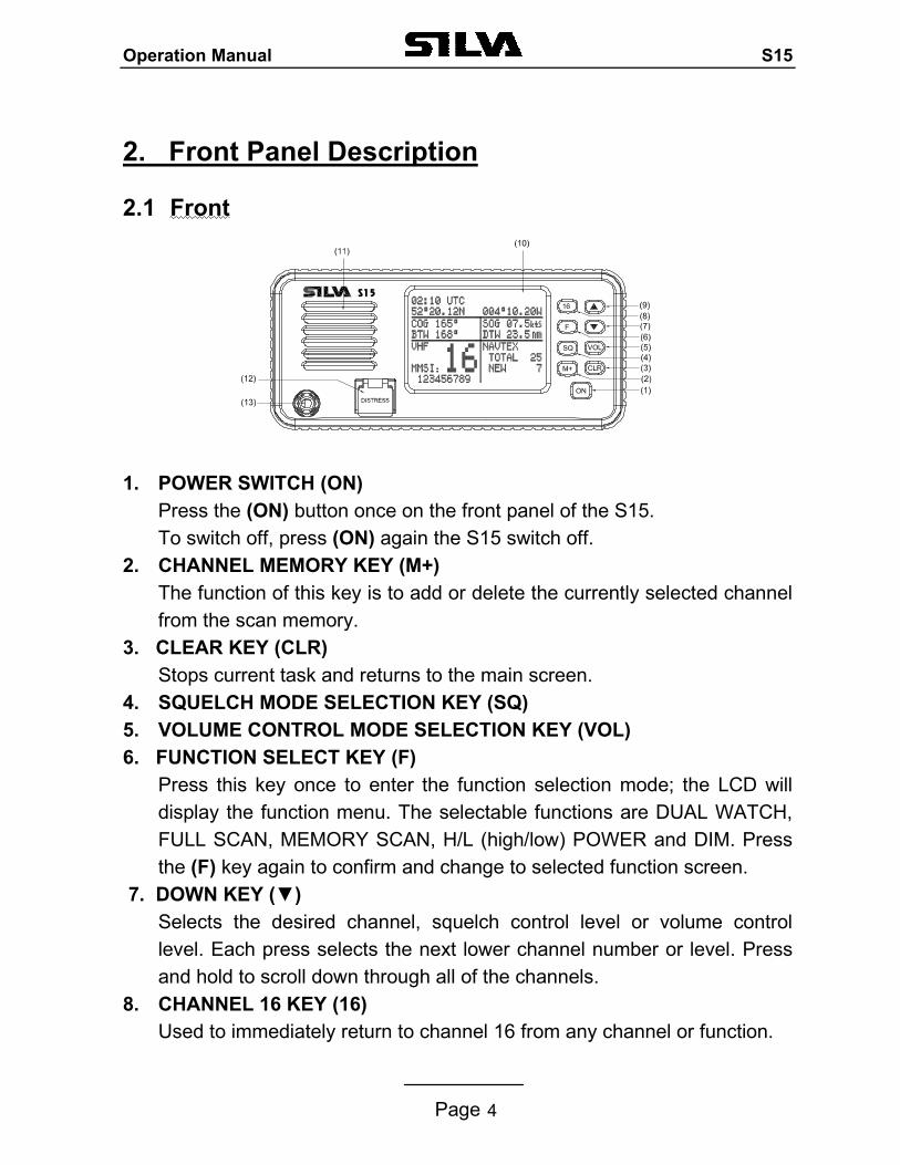
2. Front Panel Description
2.1 Front
1. POWER SWITCH (ON) Press the (ON) button once on the front panel of the S15. To switch off, press (ON) again the S15 switch off.
2. CHANNEL MEMORY KEY (M+) The function of this key is to add or delete the currently selected channel from the scan memory.
3. CLEAR KEY (CLR) Stops current task and returns to the main screen.
4. SQUELCH MODE SELECTION KEY (SQ) 5. VOLUME CONTROL MODE SELECTION KEY (VOL) 6. FUNCTION SELECT KEY (F)
Press this key once to enter the function selection mode; the LCD will display the function menu. The selectable functions are DUAL WATCH, FULL SCAN, MEMORY SCAN, H/L (high/low) POWER and DIM. Press the (F) key again to confirm and change to selected function screen.
7. DOWN KEY () Selects the desired channel, squelch control level or volume control level. Each press selects the next lower channel number or level. Press and hold to scroll down through all of the channels.
8. CHANNEL 16 KEY (16) Used to immediately return to channel 16 from any channel or function.
Operation Manual S15
Page 5
9. UP KEY () Selects the desired channel, squelch control level or volume control level. Each press selects the next higher channel, number or level. Press and hold to scroll up through all of the channels.
10. LIQUID CRYSTAL DISPLAY (LCD) Dot Matrix display, giving up to 8 lines of information.
11. SPEAKER 12. DISTRESS CALL BUTTON
The distress button as located under a protective, spring loaded cover that must be lifted before the button can be pressed.
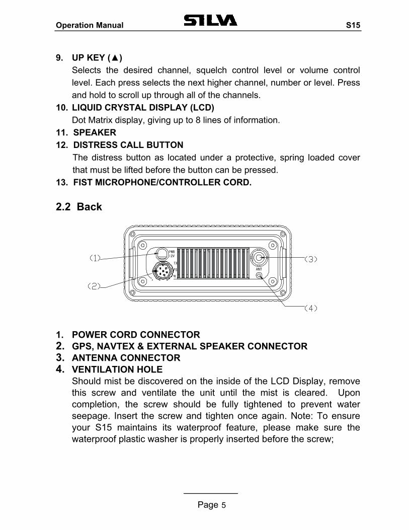
13. FIST MICROPHONE/CONTROLLER CORD. 2.2 Back 1. POWER CORD CONNECTOR 2. GPS, NAVTEX & EXTERNAL SPEAKER CONNECTOR 3. ANTENNA CONNECTOR 4. VENTILATION HOLE
Should mist be discovered on the inside of the LCD Display, remove this screw and ventilate the unit until the mist is cleared. Upon completion, the screw should be fully tightened to prevent water seepage. Insert the screw and tighten once again. Note: To ensure your S15 maintains its waterproof feature, please make sure the waterproof plastic washer is properly inserted before the screw;
Operation Manual S15
Page 6
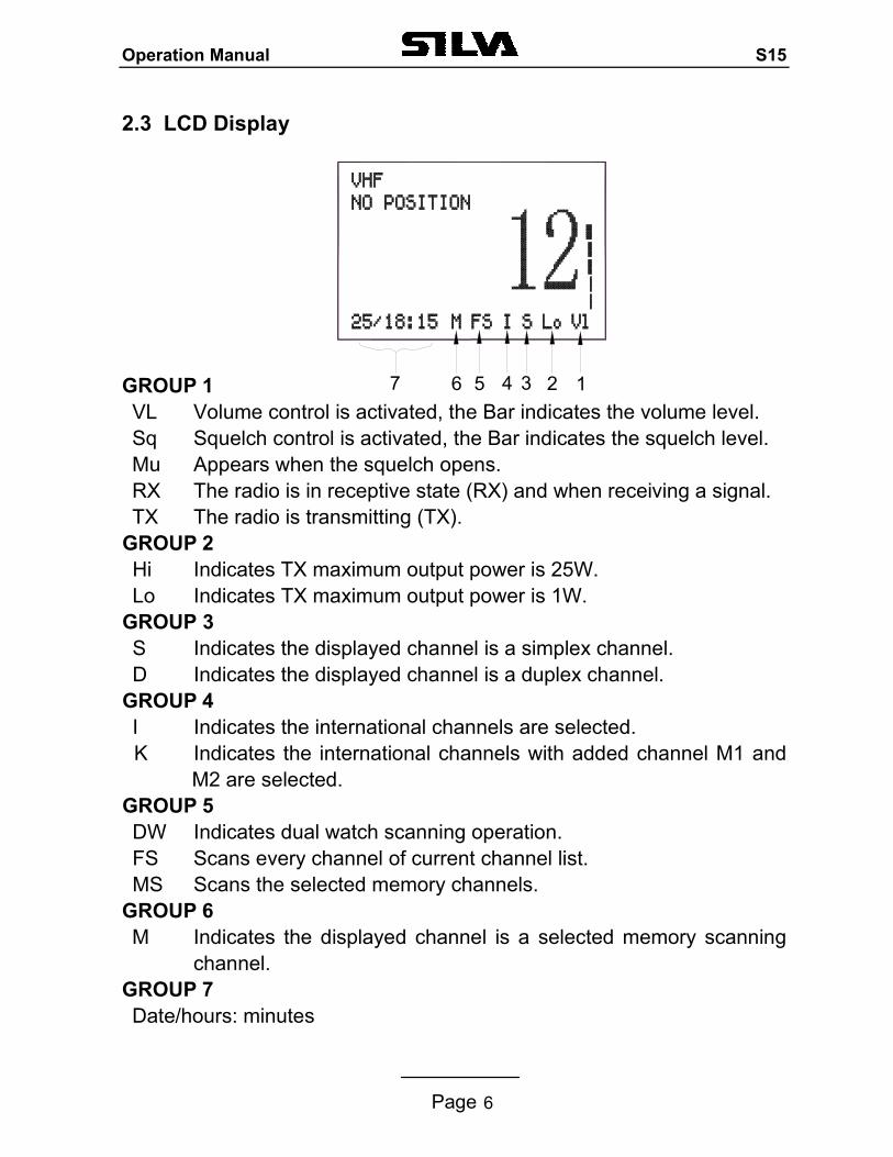
2.3 LCD Display GROUP 1 VL Volume control is activated, the Bar indicates the volume level. Sq Squelch control is activated, the Bar indicates the squelch level. Mu Appears when the squelch opens. RX The radio is in receptive state (RX) and when receiving a signal. TX The radio is transmitting (TX).
GROUP 2 Hi Indicates TX maximum output power is 25W. Lo Indicates TX maximum output power is 1W.
GROUP 3 S Indicates the displayed channel is a simplex channel. D Indicates the displayed channel is a duplex channel.
GROUP 4 I Indicates the international channels are selected. K Indicates the international channels with added channel M1 and
M2 are selected. GROUP 5 DW Indicates dual watch scanning operation. FS Scans every channel of current channel list. MS Scans the selected memory channels.
GROUP 6 M Indicates the displayed channel is a selected memory scanning
channel. GROUP 7 Date/hours: minutes
7 6 5 4 3 2 1
Operation Manual S15
Page 7
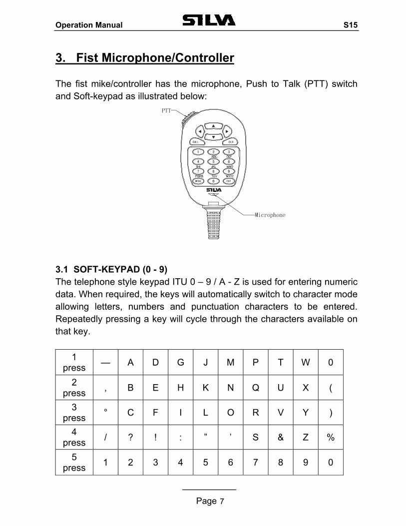
3. Fist Microphone/Controller The fist mike/controller has the microphone, Push to Talk (PTT) switch and Soft-keypad as illustrated below: 3.1 SOFT-KEYPAD (0 - 9) The telephone style keypad ITU 0 – 9 / A - Z is used for entering numeric data. When required, the keys will automatically switch to character mode allowing letters, numbers and punctuation characters to be entered. Repeatedly pressing a key will cycle through the characters available on that key.
1
press — A D G J M P T W 0
2 press , B E H K N Q U X (
3 press ° C F I L O R V Y )
4 press / ? ! : ” ’ S & Z %
5 press 1 2 3 4 5 6 7 8 9 0
Operation Manual S15
Page 8
ENTER KEY (ENT) Confirms the action. CLEAR KEY (CLR) Stop tasks and returns to main screen or returns to the last screen. / Key Moves the cursor position when setting. / KEY Use to select working channel (Up or Down). Can also be used to select stored working channels. Allows viewing of next or previous message and selection next or previous item. PTT BUTTON Keys the transmitter allowing you to transmit a message. (CALL) KEY. Activates ‘CALL’ menu.
Operation Manual S15
Page 9
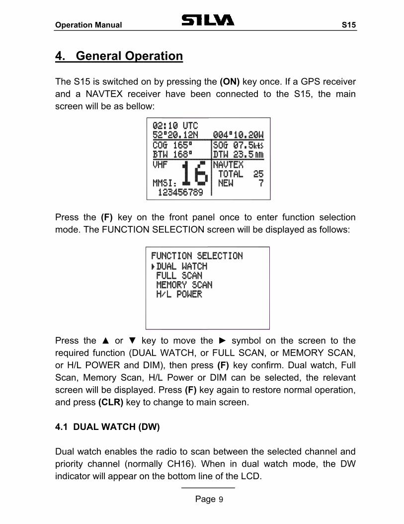
4. General Operation The S15 is switched on by pressing the (ON) key once. If a GPS receiver and a NAVTEX receiver have been connected to the S15, the main screen will be as bellow: Press the (F) key on the front panel once to enter function selection mode. The FUNCTION SELECTION screen will be displayed as follows:
Press the or key to move the symbol on the screen to the required function (DUAL WATCH, or FULL SCAN, or MEMORY SCAN, or H/L POWER and DIM), then press (F) key confirm. Dual watch, Full Scan, Memory Scan, H/L Power or DIM can be selected, the relevant screen will be displayed. Press (F) key again to restore normal operation, and press (CLR) key to change to main screen. 4.1 DUAL WATCH (DW) Dual watch enables the radio to scan between the selected channel and priority channel (normally CH16). When in dual watch mode, the DW indicator will appear on the bottom line of the LCD.
Operation Manual S15
Page 10
Note that the radio will not transmit, nor will alternative channels be able to be selected while in dual watch mode. To restore normal operation press (F) key again or press channel (16) key. 4.2 FULL SCAN (FS) This function scans through each channel sequentially until a signal is detected above the squelch level set. Once the signal ends or drops below the squelch level, the radio will continue scanning. Since the scan function stops on channels where a signal is detected, the radio will be locked. If you want the scan continue, press key once. When in Full Scan mode, FS will appear on the bottom line of LCD. Note that the radio will not transmit, nor will alternative channels be able to be selected while in Full Scan mode. To restore normal operation press (F) key or press channel (CH16) key to go to back to VHF screen.
4.3. MEMORY SCAN (MS) The Memory Scan operates in the same way as the Full Scan, except that it will only scan channels that have been entered into the Scan Memory. If no channels have been entered into the memory then this function will not available. See 4.9, Page 12. When in memory scan mode, “MS” will appear on the bottom line of the LCD. 4.4 HIGH/LOW RF OUTPUT POWER SELECTION Press or key to move the symbol on the FUNCTION SELECTION screen to required function “H/L POWER”, then press the (ENT) key for selection of low or high power, then the “Hi” or “Lo” will appear on the bottom line of the LCD.
Operation Manual S15
Page 11
4.5 SQUELCH CONTROL
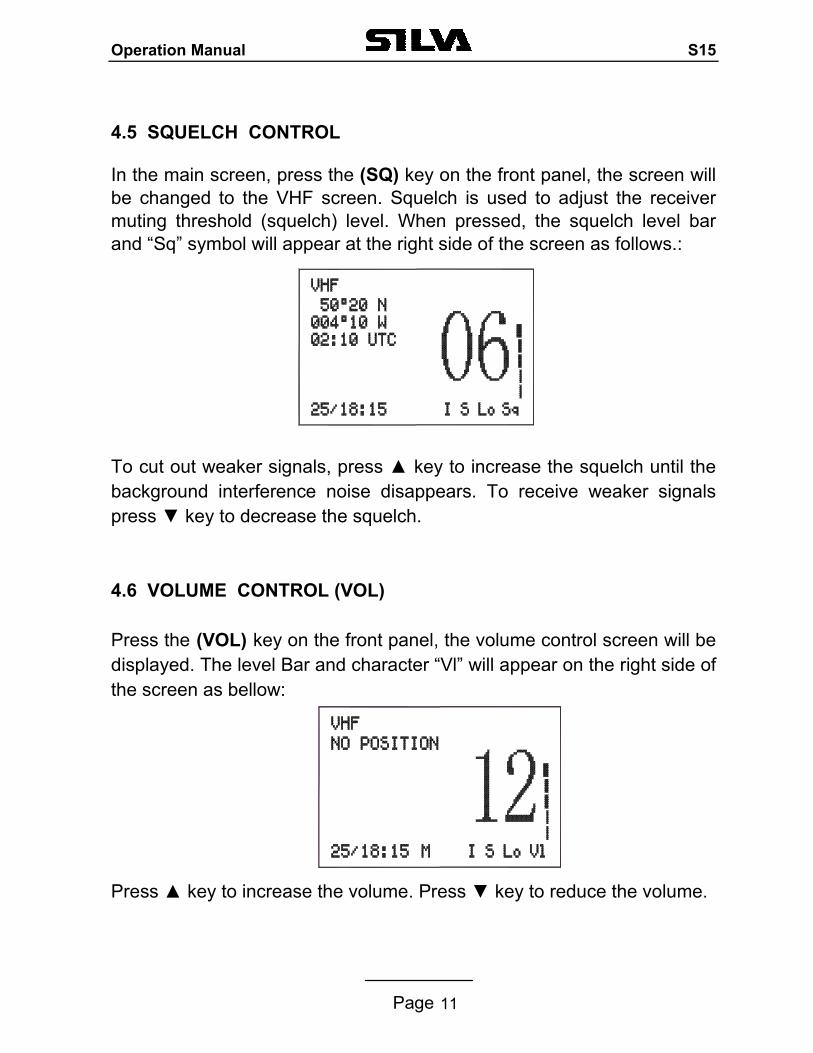
In the main screen, press the (SQ) key on the front panel, the screen will be changed to the VHF screen. Squelch is used to adjust the receiver muting threshold (squelch) level. When pressed, the squelch level bar and “Sq” symbol will appear at the right side of the screen as follows.: To cut out weaker signals, press key to increase the squelch until the background interference noise disappears. To receive weaker signals press key to decrease the squelch. 4.6 VOLUME CONTROL (VOL) Press the (VOL) key on the front panel, the volume control screen will be displayed. The level Bar and character “Vl” will appear on the right side of the screen as bellow: Press key to increase the volume. Press key to reduce the volume.
Operation Manual S15
Page 12
4.7 CHANNEL 16 (16) Pressing (16) key will automatically select channel 16 on high power. Any active function (Dual watch scanning, DSC setting, log view, NAVTEX GPS setting etc) will be cancelled. 4.8 CHANNEL SELECT ( / ) Press key to go up through the channels. Press key to go down through the channels. Channel Selection Shortcut: Select the desired channel directly from the main screen by pressing the channel number on the fist microphone/controller, and then press “ENT” to confirm.
4.9 MEMORY CHANNEL SETTING (M+) Pressing the (M+) key will add the currently selected channel into the scan memory. When operating in VHF receiver mode, if the key is pressed the screen will show “M” on the bottom right of the LCD indicating that the channel has been entered into the scan memory. By pressing the (M+) key again, the “M” will be deleted indicating that the channel is not a memory scan channel
Operation Manual S15
Page 13
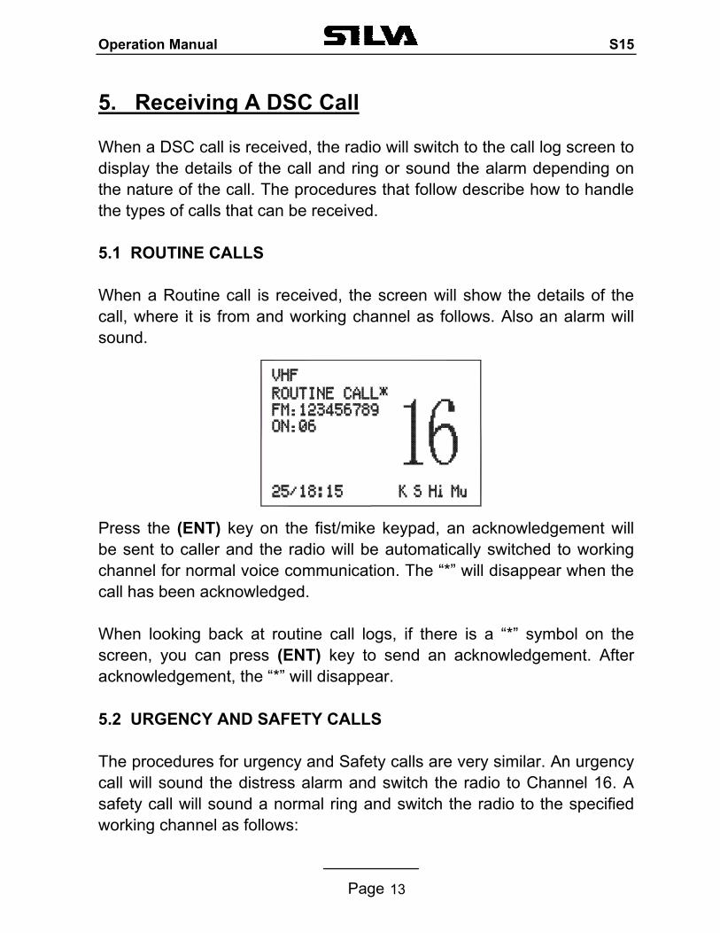
5. Receiving A DSC Call When a DSC call is received, the radio will switch to the call log screen to display the details of the call and ring or sound the alarm depending on the nature of the call. The procedures that follow describe how to handle the types of calls that can be received. 5.1 ROUTINE CALLS When a Routine call is received, the screen will show the details of the call, where it is from and working channel as follows. Also an alarm will sound. Press the (ENT) key on the fist/mike keypad, an acknowledgement will be sent to caller and the radio will be automatically switched to working channel for normal voice communication. The “*” will disappear when the call has been acknowledged. When looking back at routine call logs, if there is a “*” symbol on the screen, you can press (ENT) key to send an acknowledgement. After acknowledgement, the “*” will disappear.
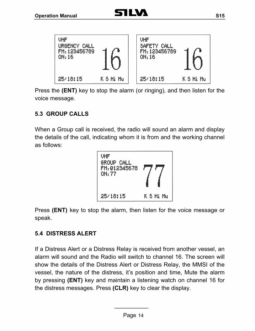
5.2 URGENCY AND SAFETY CALLS The procedures for urgency and Safety calls are very similar. An urgency call will sound the distress alarm and switch the radio to Channel 16. A safety call will sound a normal ring and switch the radio to the specified working channel as follows:
Operation Manual S15
Page 14
Press the (ENT) key to stop the alarm (or ringing), and then listen for the voice message.
5.3 GROUP CALLS When a Group call is received, the radio will sound an alarm and display the details of the call, indicating whom it is from and the working channel as follows:
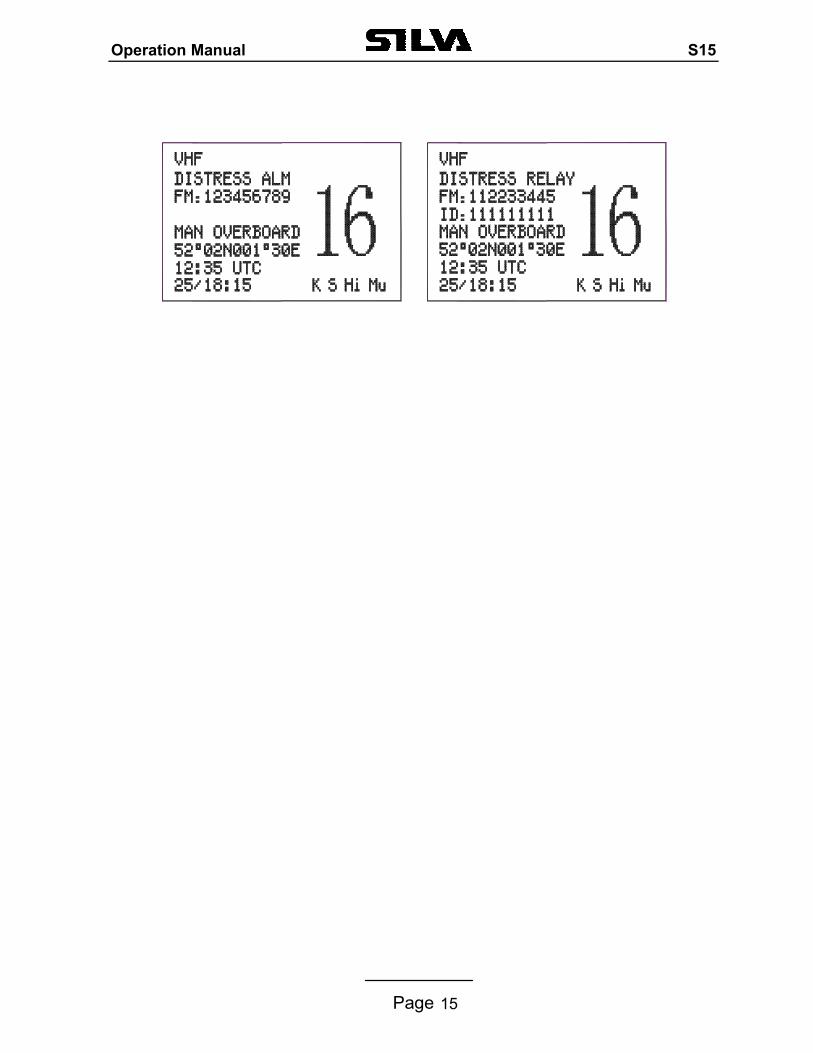
Press (ENT) key to stop the alarm, then listen for the voice message or speak. 5.4 DISTRESS ALERT If a Distress Alert or a Distress Relay is received from another vessel, an alarm will sound and the Radio will switch to channel 16. The screen will show the details of the Distress Alert or Distress Relay, the MMSI of the vessel, the nature of the distress, it’s position and time, Mute the alarm by pressing (ENT) key and maintain a listening watch on channel 16 for the distress messages. Press (CLR) key to clear the display.
Operation Manual S15
Page 15
Operation Manual S15
Page 16
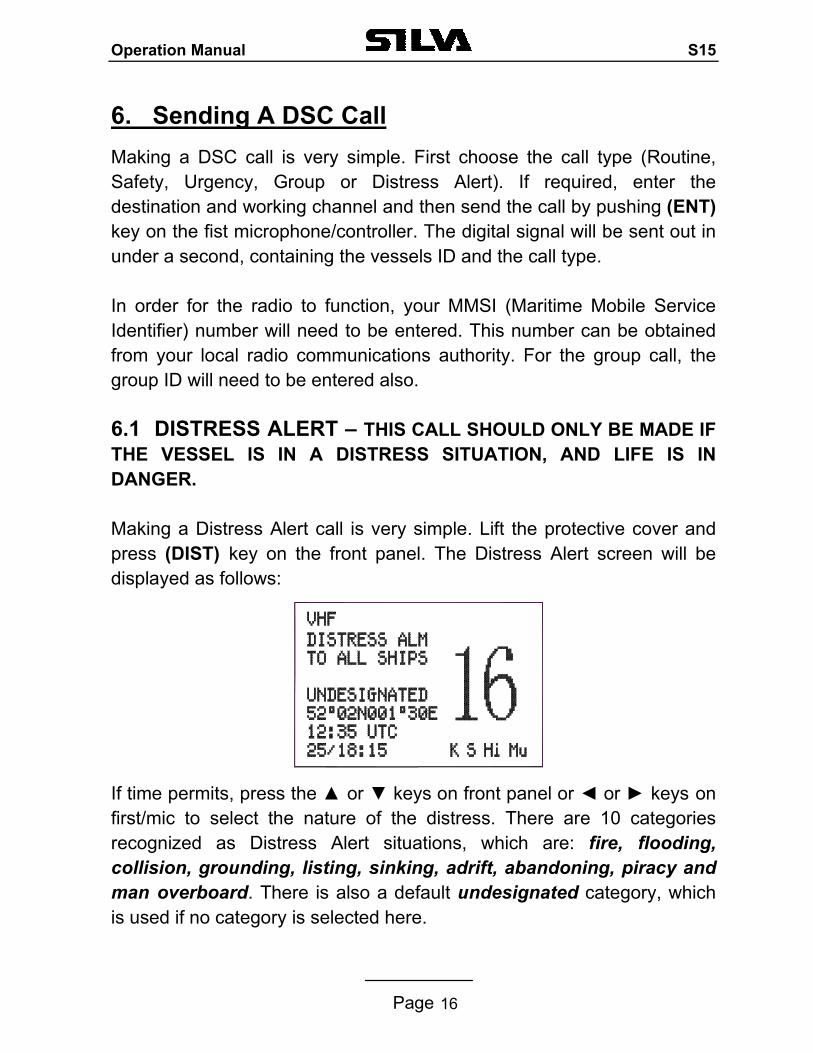
6. Sending A DSC Call Making a DSC call is very simple. First choose the call type (Routine, Safety, Urgency, Group or Distress Alert). If required, enter the destination and working channel and then send the call by pushing (ENT) key on the fist microphone/controller. The digital signal will be sent out in under a second, containing the vessels ID and the call type. In order for the radio to function, your MMSI (Maritime Mobile Service Identifier) number will need to be entered. This number can be obtained from your local radio communications authority. For the group call, the group ID will need to be entered also. 6.1 DISTRESS ALERT – THIS CALL SHOULD ONLY BE MADE IF THE VESSEL IS IN A DISTRESS SITUATION, AND LIFE IS IN DANGER. Making a Distress Alert call is very simple. Lift the protective cover and press (DIST) key on the front panel. The Distress Alert screen will be displayed as follows:
If time permits, press the or keys on front panel or or keys on first/mic to select the nature of the distress. There are 10 categories recognized as Distress Alert situations, which are: fire, flooding, collision, grounding, listing, sinking, adrift, abandoning, piracy and man overboard. There is also a default undesignated category, which is used if no category is selected here.
Operation Manual S15
Page 17
Press and hold the (DIST) key for about five seconds. A countdown to the transmission will be displayed then an alarm will sound. The Distress Alert transmission contains the following data: 1. The vessel’s MMSI; 2. The vessel’s position (either from the NMEA0183 input, or manually
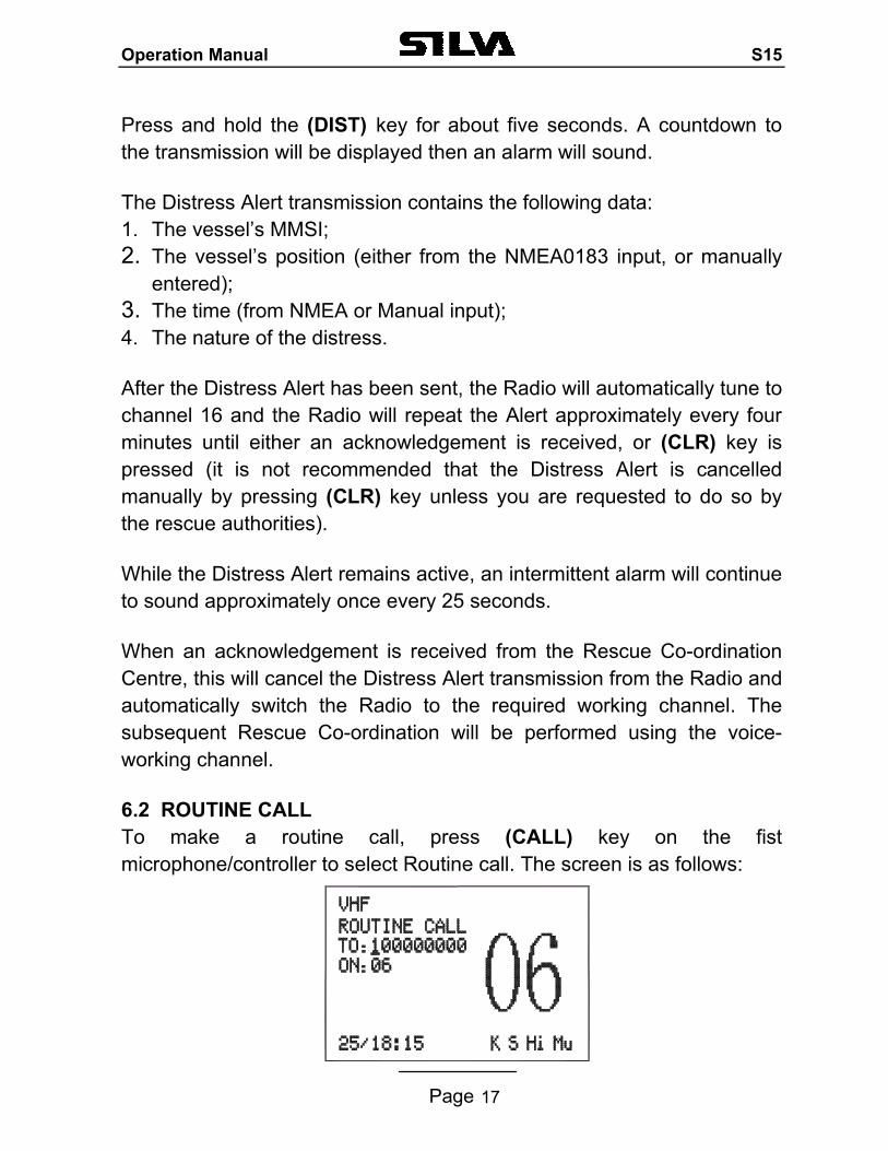
entered); 3. The time (from NMEA or Manual input); 4. The nature of the distress. After the Distress Alert has been sent, the Radio will automatically tune to channel 16 and the Radio will repeat the Alert approximately every four minutes until either an acknowledgement is received, or (CLR) key is pressed (it is not recommended that the Distress Alert is cancelled manually by pressing (CLR) key unless you are requested to do so by the rescue authorities). While the Distress Alert remains active, an intermittent alarm will continue to sound approximately once every 25 seconds. When an acknowledgement is received from the Rescue Co-ordination Centre, this will cancel the Distress Alert transmission from the Radio and automatically switch the Radio to the required working channel. The subsequent Rescue Co-ordination will be performed using the voice-working channel. 6.2 ROUTINE CALL To make a routine call, press (CALL) key on the fist microphone/controller to select Routine call. The screen is as follows:
Operation Manual S15
Page 18
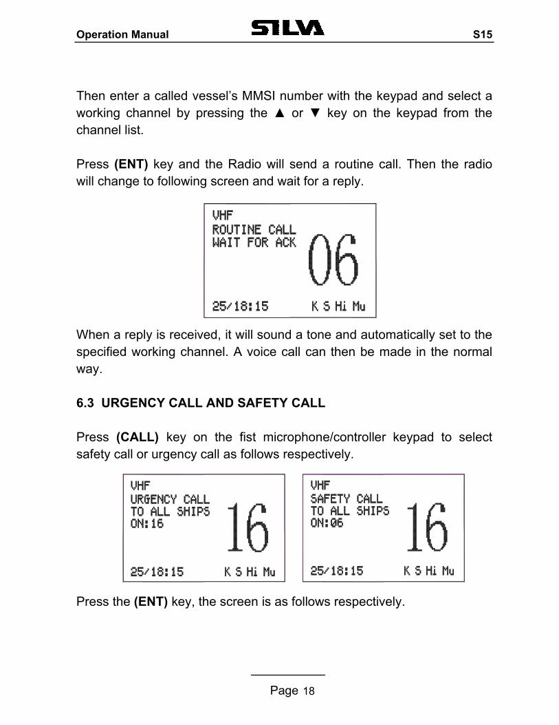
Then enter a called vessel’s MMSI number with the keypad and select a working channel by pressing the or key on the keypad from the channel list. Press (ENT) key and the Radio will send a routine call. Then the radio will change to following screen and wait for a reply. When a reply is received, it will sound a tone and automatically set to the specified working channel. A voice call can then be made in the normal way. 6.3 URGENCY CALL AND SAFETY CALL Press (CALL) key on the fist microphone/controller keypad to select safety call or urgency call as follows respectively. Press the (ENT) key, the screen is as follows respectively.
Operation Manual S15
Page 19
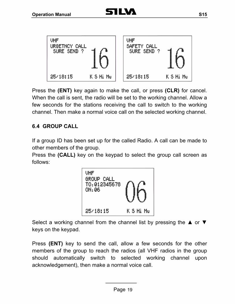
Press the (ENT) key again to make the call, or press (CLR) for cancel. When the call is sent, the radio will be set to the working channel. Allow a few seconds for the stations receiving the call to switch to the working channel. Then make a normal voice call on the selected working channel.
6.4 GROUP CALL If a group ID has been set up for the called Radio. A call can be made to other members of the group. Press the (CALL) key on the keypad to select the group call screen as follows:
Select a working channel from the channel list by pressing the or keys on the keypad. Press (ENT) key to send the call, allow a few seconds for the other members of the group to reach the radios (all VHF radios in the group should automatically switch to selected working channel upon acknowledgement), then make a normal voice call.
Operation Manual S15
Page 20
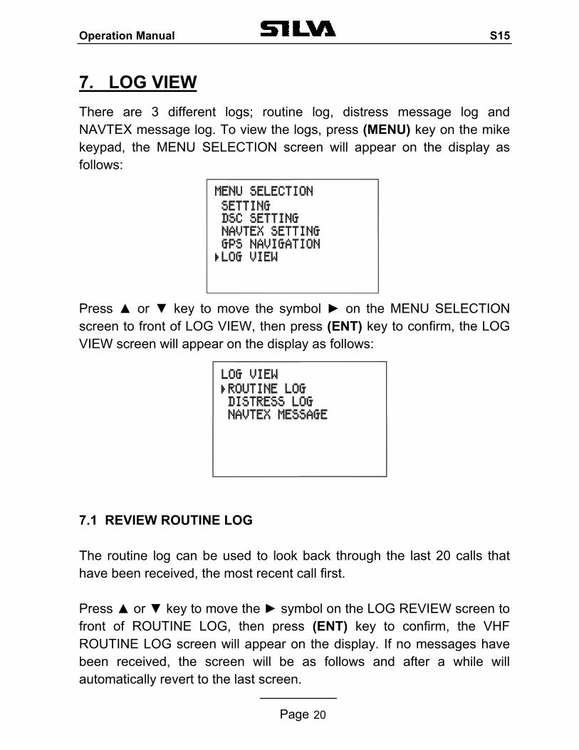
7. LOG VIEW There are 3 different logs; routine log, distress message log and NAVTEX message log. To view the logs, press (MENU) key on the mike keypad, the MENU SELECTION screen will appear on the display as follows:
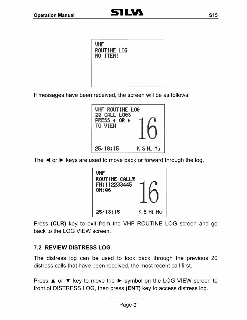
Press or key to move the symbol on the MENU SELECTION screen to front of LOG VIEW, then press (ENT) key to confirm, the LOG VIEW screen will appear on the display as follows: 7.1 REVIEW ROUTINE LOG The routine log can be used to look back through the last 20 calls that have been received, the most recent call first. Press or key to move the symbol on the LOG REVIEW screen to front of ROUTINE LOG, then press (ENT) key to confirm, the VHF ROUTINE LOG screen will appear on the display. If no messages have been received, the screen will be as follows and after a while will automatically revert to the last screen.
Operation Manual S15
Page 21
If messages have been received, the screen will be as follows: The or keys are used to move back or forward through the log. Press (CLR) key to exit from the VHF ROUTINE LOG screen and go back to the LOG VIEW screen. 7.2 REVIEW DISTRESS LOG
The distress log can be used to look back through the previous 20 distress calls that have been received, the most recent call first. Press or key to move the symbol on the LOG VIEW screen to front of DISTRESS LOG, then press (ENT) key to access distress log.
Operation Manual S15
Page 22
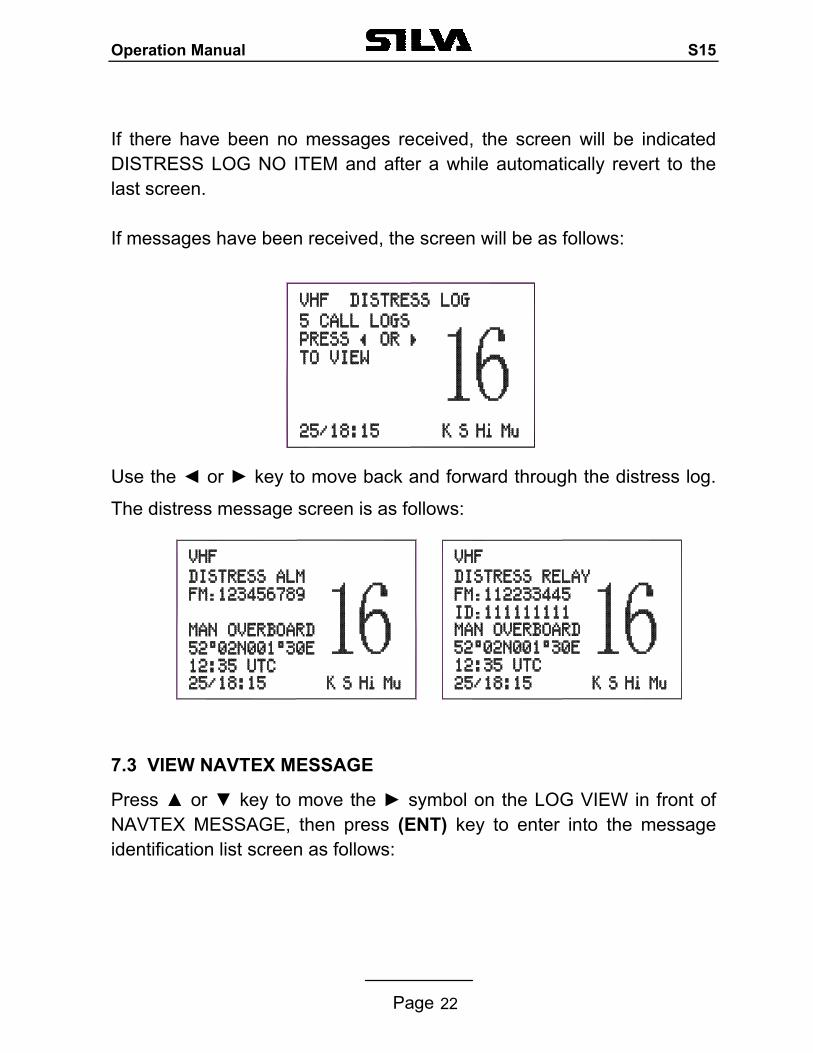
If there have been no messages received, the screen will be indicated DISTRESS LOG NO ITEM and after a while automatically revert to the last screen. If messages have been received, the screen will be as follows: Use the or key to move back and forward through the distress log.
The distress message screen is as follows:
7.3 VIEW NAVTEX MESSAGE
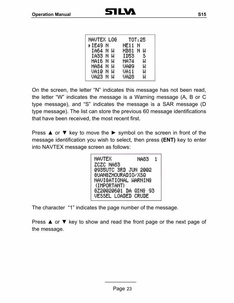
Press or key to move the symbol on the LOG VIEW in front of NAVTEX MESSAGE, then press (ENT) key to enter into the message identification list screen as follows:
Operation Manual S15
Page 23
On the screen, the letter “N” indicates this message has not been read, the letter “W” indicates the message is a Warning message (A, B or C type message), and “S” indicates the message is a SAR message (D type message). The list can store the previous 60 message identifications that have been received, the most recent first. Press or key to move the symbol on the screen in front of the message identification you wish to select, then press (ENT) key to enter into NAVTEX message screen as follows: The character “1” indicates the page number of the message. Press or key to show and read the front page or the next page of the message.
Operation Manual S15
Page 24
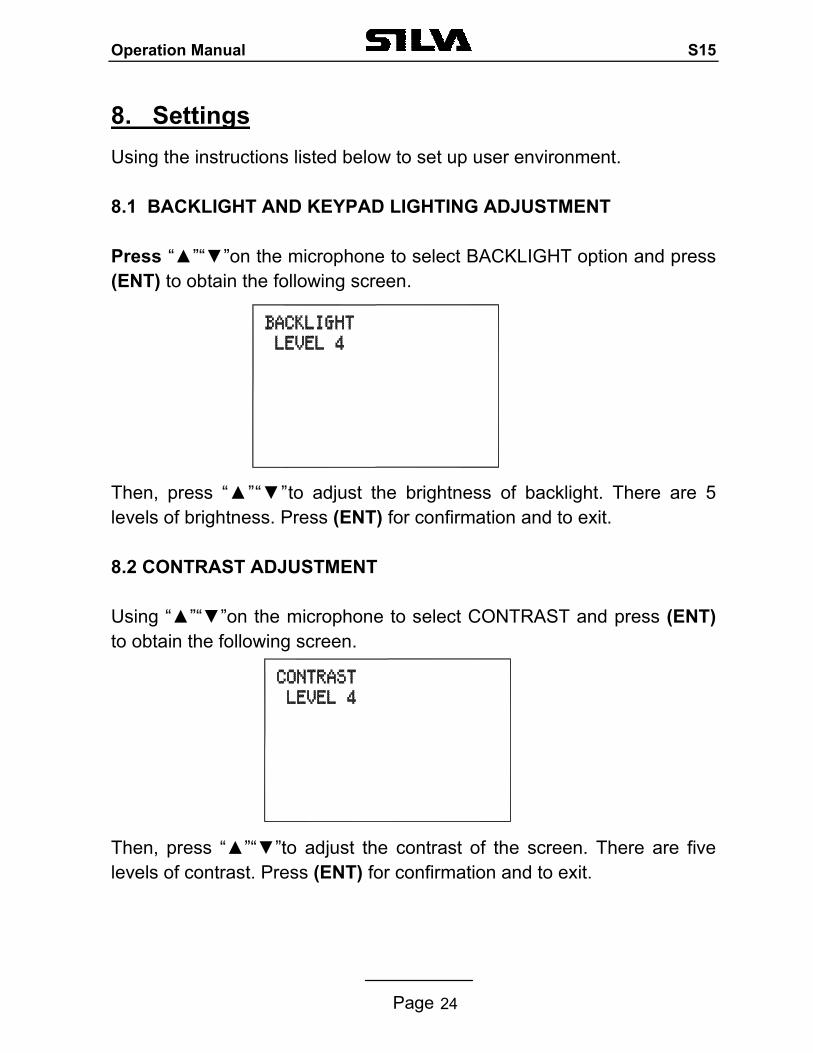
8. Settings Using the instructions listed below to set up user environment. 8.1 BACKLIGHT AND KEYPAD LIGHTING ADJUSTMENT Press “”“”on the microphone to select BACKLIGHT option and press (ENT) to obtain the following screen.
Then, press “”“”to adjust the brightness of backlight. There are 5 levels of brightness. Press (ENT) for confirmation and to exit. 8.2 CONTRAST ADJUSTMENT Using “”“”on the microphone to select CONTRAST and press (ENT) to obtain the following screen.
Then, press “”“”to adjust the contrast of the screen. There are five levels of contrast. Press (ENT) for confirmation and to exit.
Operation Manual S15
Page 25
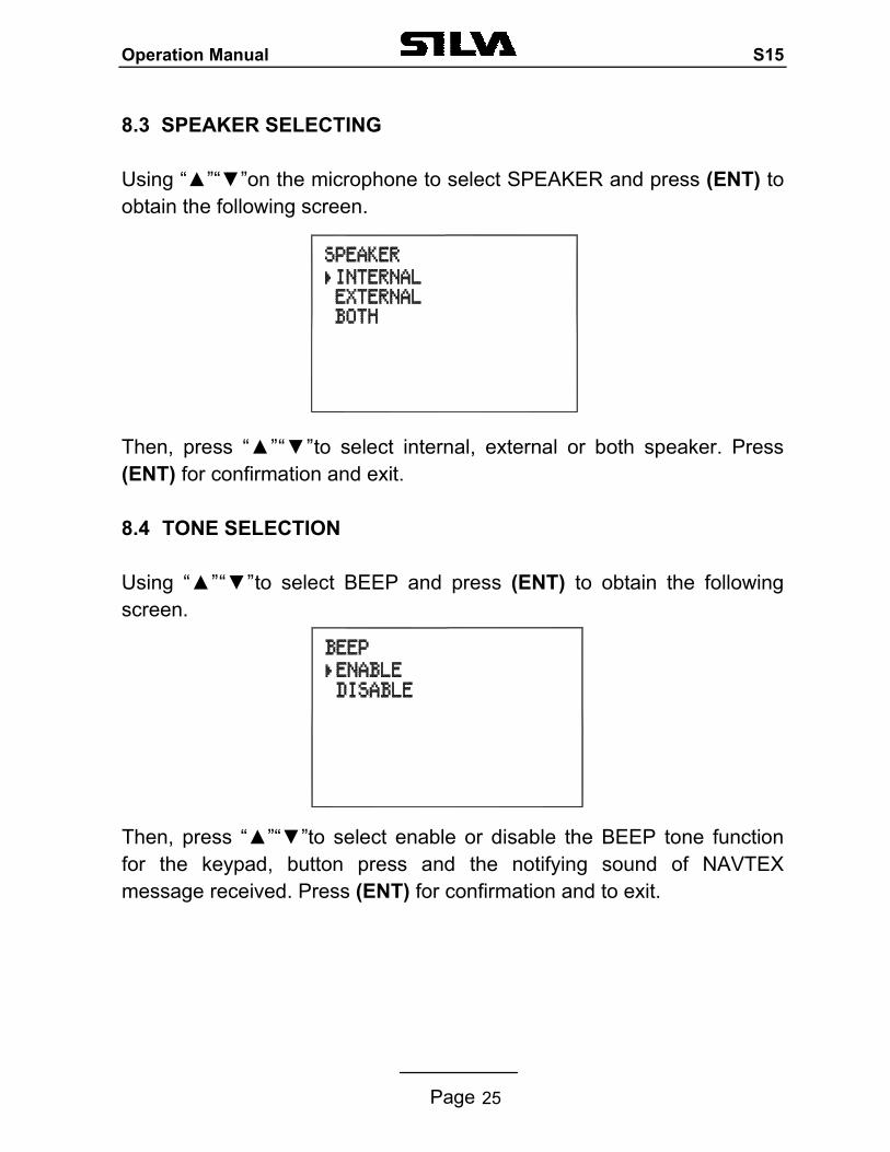
8.3 SPEAKER SELECTING Using “”“”on the microphone to select SPEAKER and press (ENT) to obtain the following screen.
Then, press “”“”to select internal, external or both speaker. Press (ENT) for confirmation and exit. 8.4 TONE SELECTION Using “”“”to select BEEP and press (ENT) to obtain the following screen.
Then, press “”“”to select enable or disable the BEEP tone function for the keypad, button press and the notifying sound of NAVTEX message received. Press (ENT) for confirmation and to exit.
Operation Manual S15
Page 26
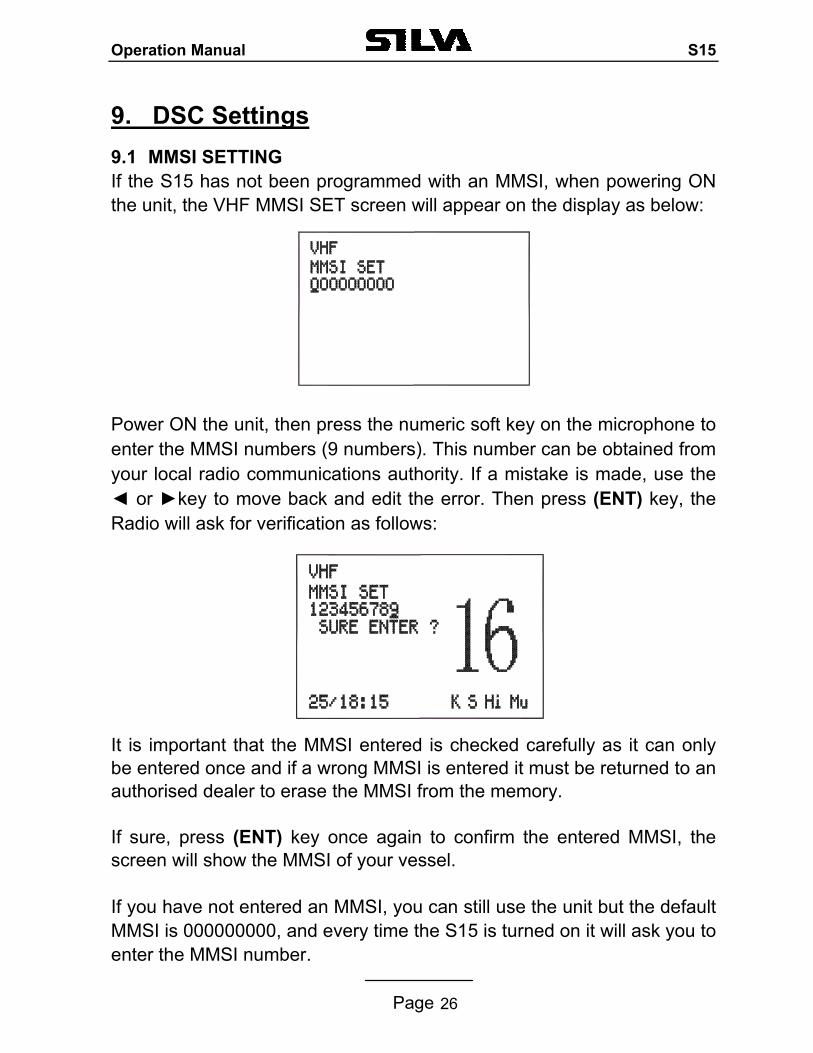
9. DSC Settings 9.1 MMSI SETTING If the S15 has not been programmed with an MMSI, when powering ON the unit, the VHF MMSI SET screen will appear on the display as below:
Power ON the unit, then press the numeric soft key on the microphone to enter the MMSI numbers (9 numbers). This number can be obtained from your local radio communications authority. If a mistake is made, use the or key to move back and edit the error. Then press (ENT) key, the Radio will ask for verification as follows:
It is important that the MMSI entered is checked carefully as it can only be entered once and if a wrong MMSI is entered it must be returned to an authorised dealer to erase the MMSI from the memory. If sure, press (ENT) key once again to confirm the entered MMSI, the screen will show the MMSI of your vessel. If you have not entered an MMSI, you can still use the unit but the default MMSI is 000000000, and every time the S15 is turned on it will ask you to enter the MMSI number.
Operation Manual S15
Page 27
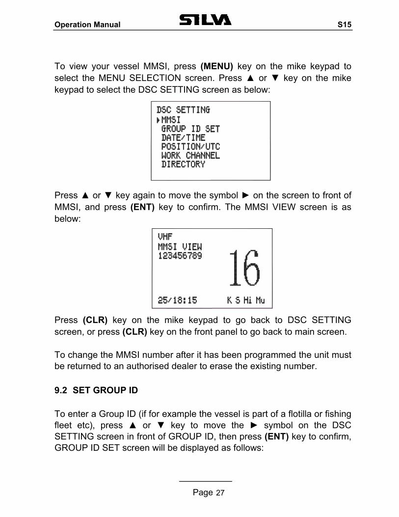
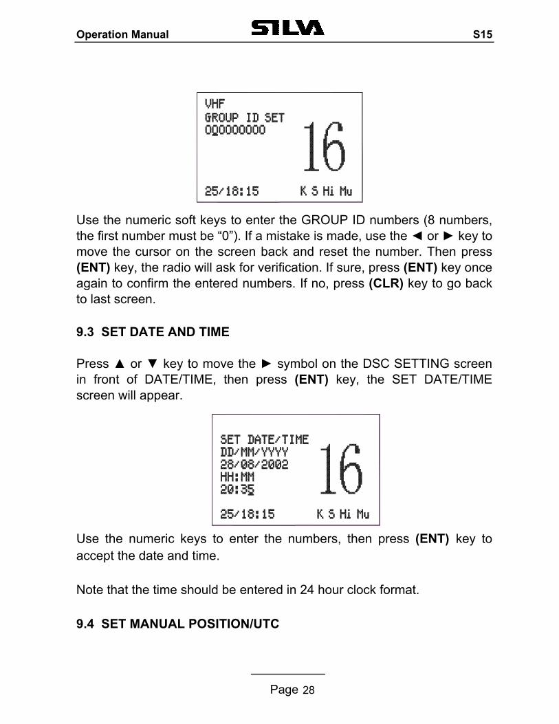
To view your vessel MMSI, press (MENU) key on the mike keypad to select the MENU SELECTION screen. Press or key on the mike keypad to select the DSC SETTING screen as below: Press or key again to move the symbol on the screen to front of MMSI, and press (ENT) key to confirm. The MMSI VIEW screen is as below: Press (CLR) key on the mike keypad to go back to DSC SETTING screen, or press (CLR) key on the front panel to go back to main screen. To change the MMSI number after it has been programmed the unit must be returned to an authorised dealer to erase the existing number. 9.2 SET GROUP ID To enter a Group ID (if for example the vessel is part of a flotilla or fishing fleet etc), press or key to move the symbol on the DSC SETTING screen in front of GROUP ID, then press (ENT) key to confirm, GROUP ID SET screen will be displayed as follows:
Operation Manual S15
Page 28
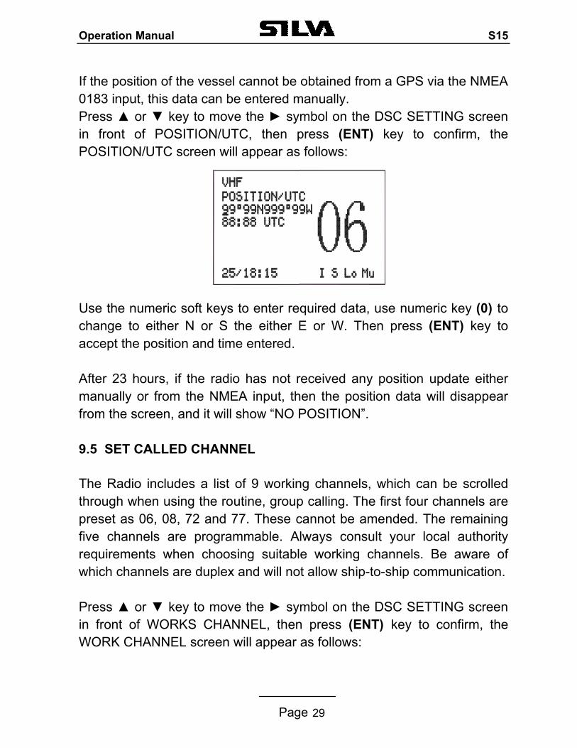
Use the numeric soft keys to enter the GROUP ID numbers (8 numbers, the first number must be “0”). If a mistake is made, use the or key to move the cursor on the screen back and reset the number. Then press (ENT) key, the radio will ask for verification. If sure, press (ENT) key once again to confirm the entered numbers. If no, press (CLR) key to go back to last screen. 9.3 SET DATE AND TIME Press or key to move the symbol on the DSC SETTING screen in front of DATE/TIME, then press (ENT) key, the SET DATE/TIME screen will appear. Use the numeric keys to enter the numbers, then press (ENT) key to accept the date and time. Note that the time should be entered in 24 hour clock format. 9.4 SET MANUAL POSITION/UTC
Operation Manual S15
Page 29
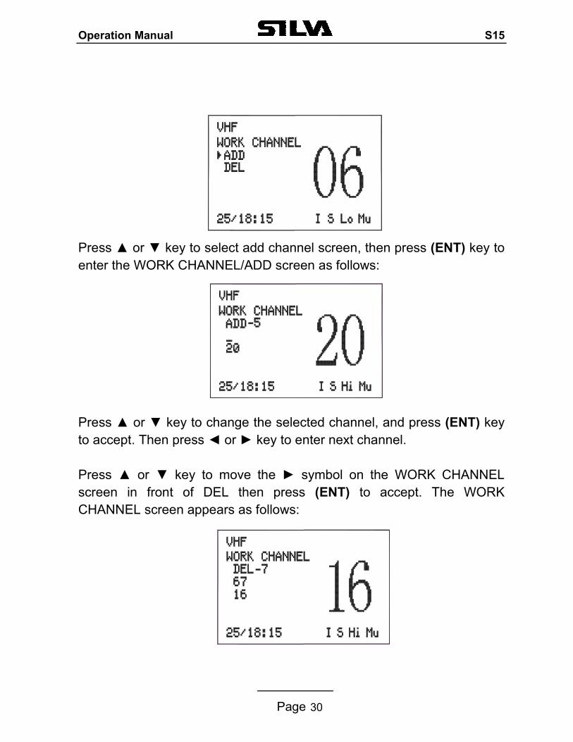
If the position of the vessel cannot be obtained from a GPS via the NMEA 0183 input, this data can be entered manually. Press or key to move the symbol on the DSC SETTING screen in front of POSITION/UTC, then press (ENT) key to confirm, the POSITION/UTC screen will appear as follows: Use the numeric soft keys to enter required data, use numeric key (0) to change to either N or S the either E or W. Then press (ENT) key to accept the position and time entered. After 23 hours, if the radio has not received any position update either manually or from the NMEA input, then the position data will disappear from the screen, and it will show “NO POSITION”.
9.5 SET CALLED CHANNEL The Radio includes a list of 9 working channels, which can be scrolled through when using the routine, group calling. The first four channels are preset as 06, 08, 72 and 77. These cannot be amended. The remaining five channels are programmable. Always consult your local authority requirements when choosing suitable working channels. Be aware of which channels are duplex and will not allow ship-to-ship communication. Press or key to move the symbol on the DSC SETTING screen in front of WORKS CHANNEL, then press (ENT) key to confirm, the WORK CHANNEL screen will appear as follows:
Operation Manual S15
Page 30
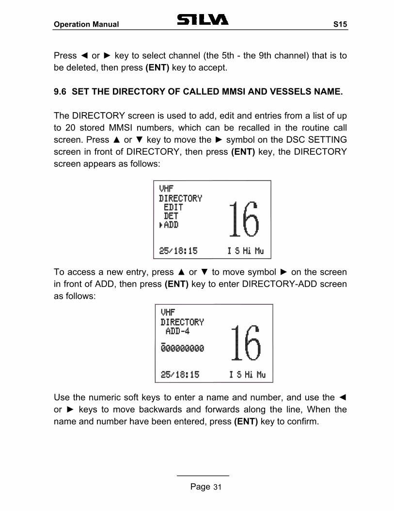
Press or key to select add channel screen, then press (ENT) key to enter the WORK CHANNEL/ADD screen as follows: Press or key to change the selected channel, and press (ENT) key to accept. Then press or key to enter next channel. Press or key to move the symbol on the WORK CHANNEL screen in front of DEL then press (ENT) to accept. The WORK CHANNEL screen appears as follows:
Operation Manual S15
Page 31
Press or key to select channel (the 5th - the 9th channel) that is to be deleted, then press (ENT) key to accept. 9.6 SET THE DIRECTORY OF CALLED MMSI AND VESSELS NAME. The DIRECTORY screen is used to add, edit and entries from a list of up to 20 stored MMSI numbers, which can be recalled in the routine call screen. Press or key to move the symbol on the DSC SETTING screen in front of DIRECTORY, then press (ENT) key, the DIRECTORY screen appears as follows: To access a new entry, press or to move symbol on the screen in front of ADD, then press (ENT) key to enter DIRECTORY-ADD screen as follows:
Use the numeric soft keys to enter a name and number, and use the or keys to move backwards and forwards along the line, When the name and number have been entered, press (ENT) key to confirm.
Operation Manual S15
Page 32
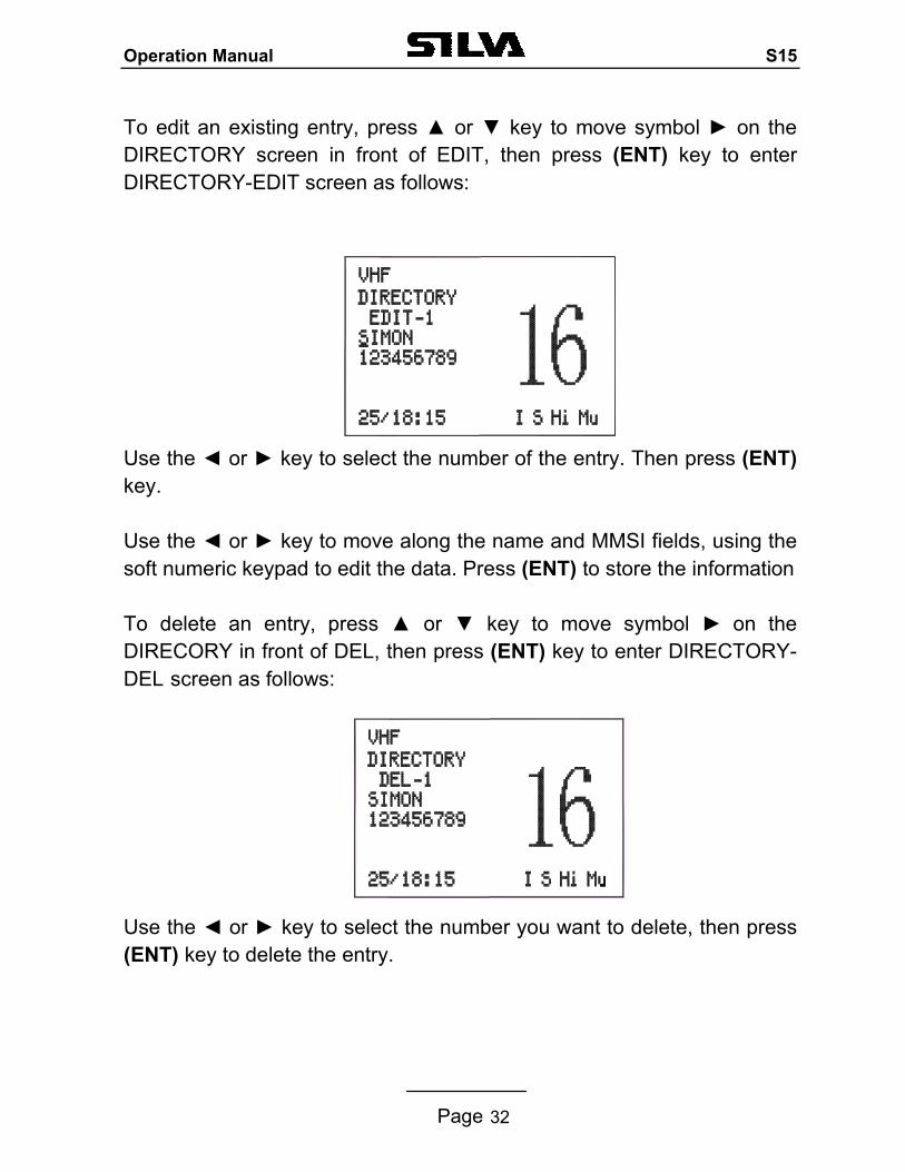
To edit an existing entry, press or key to move symbol on the DIRECTORY screen in front of EDIT, then press (ENT) key to enter DIRECTORY-EDIT screen as follows: Use the or key to select the number of the entry. Then press (ENT) key.
Use the or key to move along the name and MMSI fields, using the soft numeric keypad to edit the data. Press (ENT) to store the information
To delete an entry, press or key to move symbol on the DIRECORY in front of DEL, then press (ENT) key to enter DIRECTORY-DEL screen as follows: Use the or key to select the number you want to delete, then press (ENT) key to delete the entry.
Operation Manual S15
Page 33
10. NAVTEX Setting To limit the number of message displayed in the NAVTEX log you can select what station and also what type of message you wish to select. 10.1 STATION SELECTION
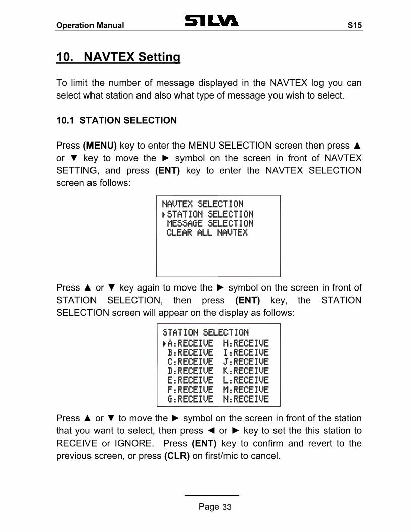
Press (MENU) key to enter the MENU SELECTION screen then press or key to move the symbol on the screen in front of NAVTEX SETTING, and press (ENT) key to enter the NAVTEX SELECTION screen as follows: Press or key again to move the symbol on the screen in front of STATION SELECTION, then press (ENT) key, the STATION SELECTION screen will appear on the display as follows: Press or to move the symbol on the screen in front of the station that you want to select, then press or key to set the this station to RECEIVE or IGNORE. Press (ENT) key to confirm and revert to the previous screen, or press (CLR) on first/mic to cancel.
Operation Manual S15
Page 34
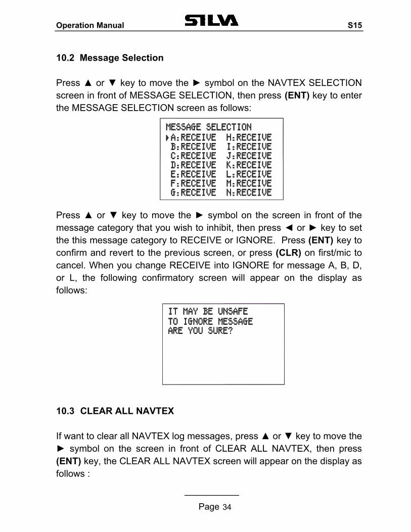
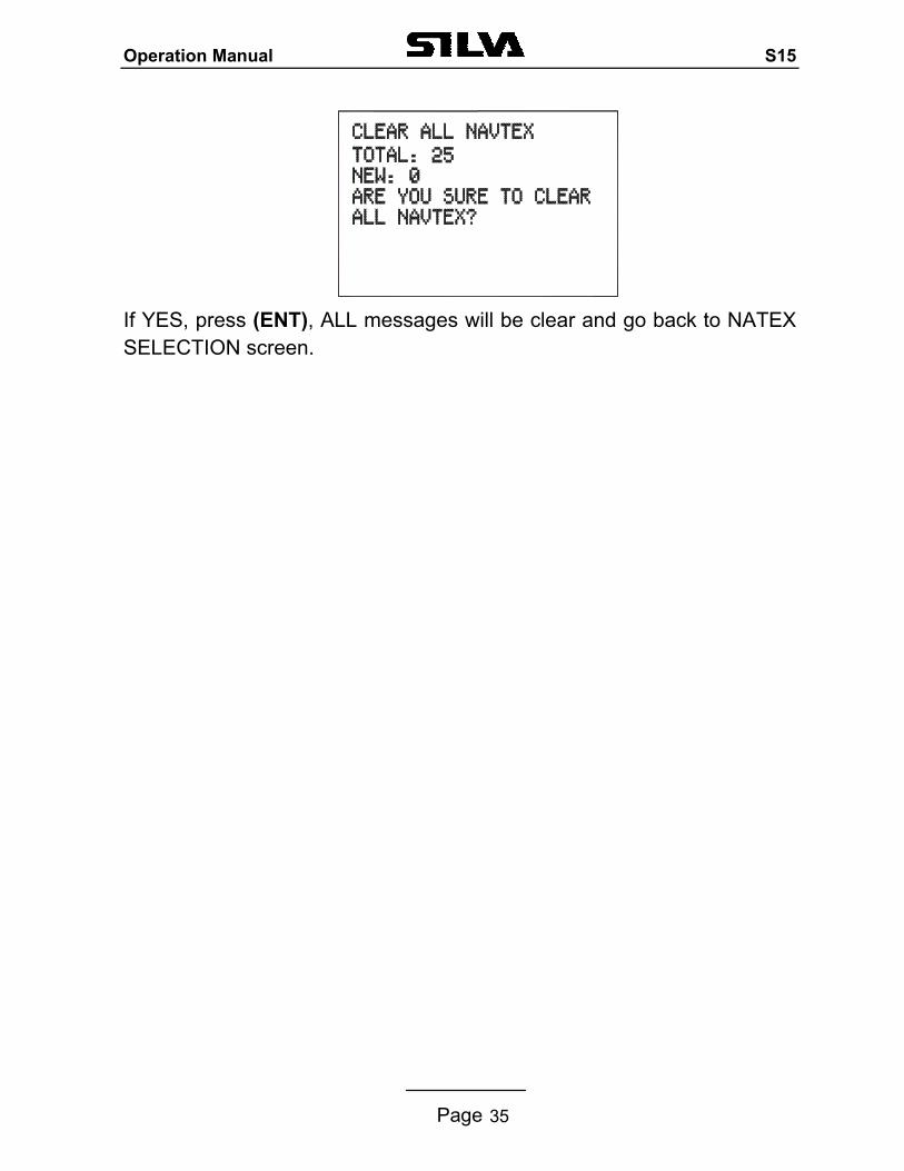
10.2 Message Selection Press or key to move the symbol on the NAVTEX SELECTION screen in front of MESSAGE SELECTION, then press (ENT) key to enter the MESSAGE SELECTION screen as follows: Press or key to move the symbol on the screen in front of the message category that you wish to inhibit, then press or key to set the this message category to RECEIVE or IGNORE. Press (ENT) key to confirm and revert to the previous screen, or press (CLR) on first/mic to cancel. When you change RECEIVE into IGNORE for message A, B, D, or L, the following confirmatory screen will appear on the display as follows: 10.3 CLEAR ALL NAVTEX If want to clear all NAVTEX log messages, press or key to move the symbol on the screen in front of CLEAR ALL NAVTEX, then press (ENT) key, the CLEAR ALL NAVTEX screen will appear on the display as follows :
Operation Manual S15
Page 35
If YES, press (ENT), ALL messages will be clear and go back to NATEX SELECTION screen.
Operation Manual S15
Page 36
11. GPS Navigation Settings
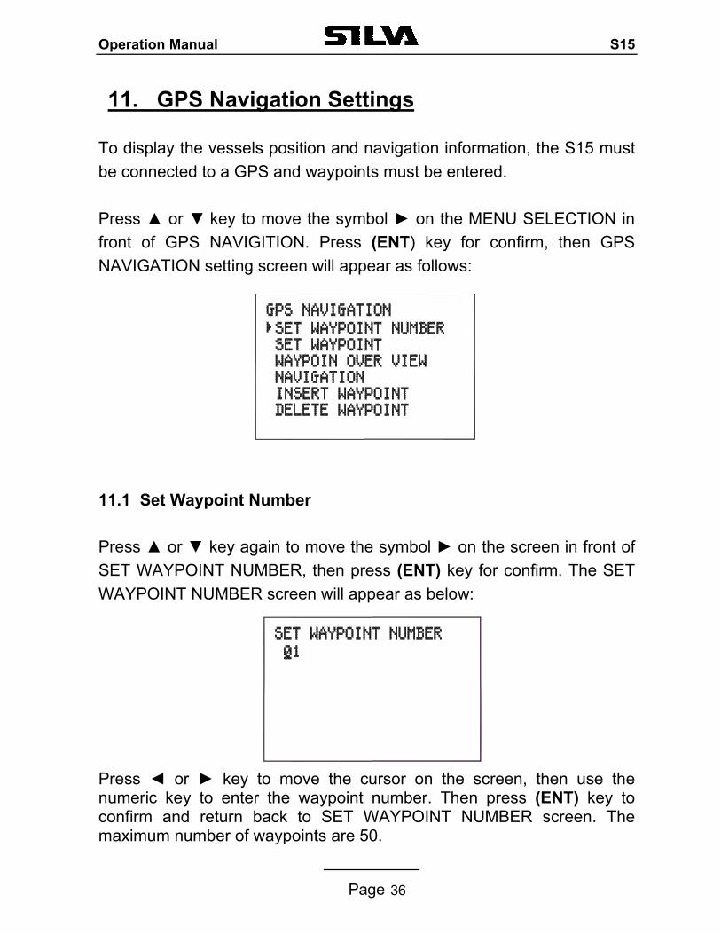
To display the vessels position and navigation information, the S15 must be connected to a GPS and waypoints must be entered. Press or key to move the symbol on the MENU SELECTION in front of GPS NAVIGITION. Press (ENT) key for confirm, then GPS NAVIGATION setting screen will appear as follows: 11.1 Set Waypoint Number Press or key again to move the symbol on the screen in front of SET WAYPOINT NUMBER, then press (ENT) key for confirm. The SET WAYPOINT NUMBER screen will appear as below: Press or key to move the cursor on the screen, then use the numeric key to enter the waypoint number. Then press (ENT) key to confirm and return back to SET WAYPOINT NUMBER screen. The maximum number of waypoints are 50.
Operation Manual S15
Page 37
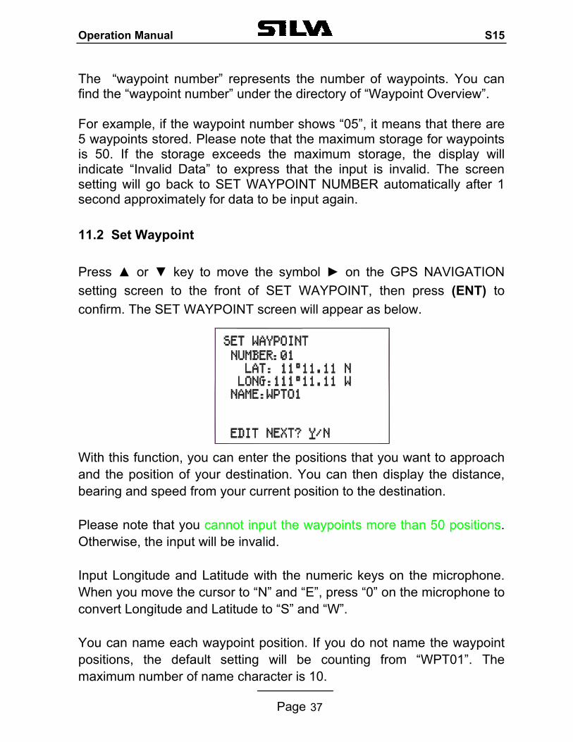
The “waypoint number” represents the number of waypoints. You can find the “waypoint number” under the directory of “Waypoint Overview”. For example, if the waypoint number shows “05”, it means that there are 5 waypoints stored. Please note that the maximum storage for waypoints is 50. If the storage exceeds the maximum storage, the display will indicate “Invalid Data” to express that the input is invalid. The screen setting will go back to SET WAYPOINT NUMBER automatically after 1 second approximately for data to be input again. 11.2 Set Waypoint Press or key to move the symbol on the GPS NAVIGATION setting screen to the front of SET WAYPOINT, then press (ENT) to confirm. The SET WAYPOINT screen will appear as below. With this function, you can enter the positions that you want to approach and the position of your destination. You can then display the distance, bearing and speed from your current position to the destination. Please note that you cannot input the waypoints more than 50 positions. Otherwise, the input will be invalid. Input Longitude and Latitude with the numeric keys on the microphone. When you move the cursor to “N” and “E”, press “0” on the microphone to convert Longitude and Latitude to “S” and “W”. You can name each waypoint position. If you do not name the waypoint positions, the default setting will be counting from “WPT01”. The maximum number of name character is 10.
Operation Manual S15
Page 38
If need enter the next waypoint, press (ENT) key, or press (CLR) key to return back to GPS NAVIGITION setting screen.
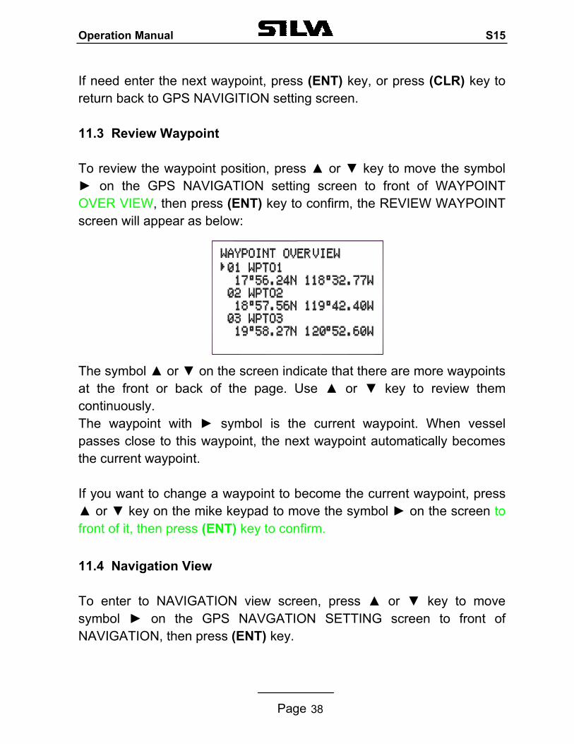
11.3 Review Waypoint To review the waypoint position, press or key to move the symbol on the GPS NAVIGATION setting screen to front of WAYPOINT OVER VIEW, then press (ENT) key to confirm, the REVIEW WAYPOINT screen will appear as below:
The symbol or on the screen indicate that there are more waypoints at the front or back of the page. Use or key to review them continuously. The waypoint with symbol is the current waypoint. When vessel passes close to this waypoint, the next waypoint automatically becomes the current waypoint. If you want to change a waypoint to become the current waypoint, press or key on the mike keypad to move the symbol on the screen to front of it, then press (ENT) key to confirm.
11.4 Navigation View To enter to NAVIGATION view screen, press or key to move symbol on the GPS NAVGATION SETTING screen to front of NAVIGATION, then press (ENT) key.
Operation Manual S15
Page 39
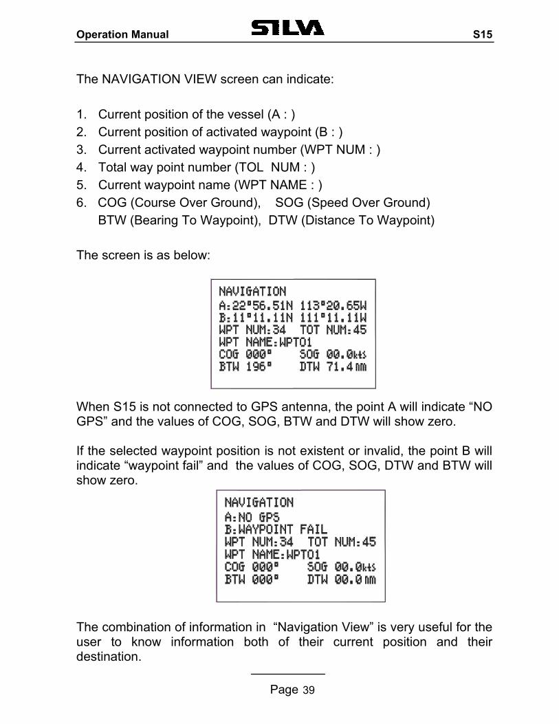
The NAVIGATION VIEW screen can indicate:
1. Current position of the vessel (A : ) 2. Current position of activated waypoint (B : ) 3. Current activated waypoint number (WPT NUM : ) 4. Total way point number (TOL NUM : ) 5. Current waypoint name (WPT NAME : ) 6. COG (Course Over Ground), SOG (Speed Over Ground)
BTW (Bearing To Waypoint), DTW (Distance To Waypoint)
The screen is as below:
When S15 is not connected to GPS antenna, the point A will indicate “NO GPS” and the values of COG, SOG, BTW and DTW will show zero. If the selected waypoint position is not existent or invalid, the point B will indicate “waypoint fail” and the values of COG, SOG, DTW and BTW will show zero. The combination of information in “Navigation View” is very useful for the user to know information both of their current position and their destination.
Operation Manual S15
Page 40
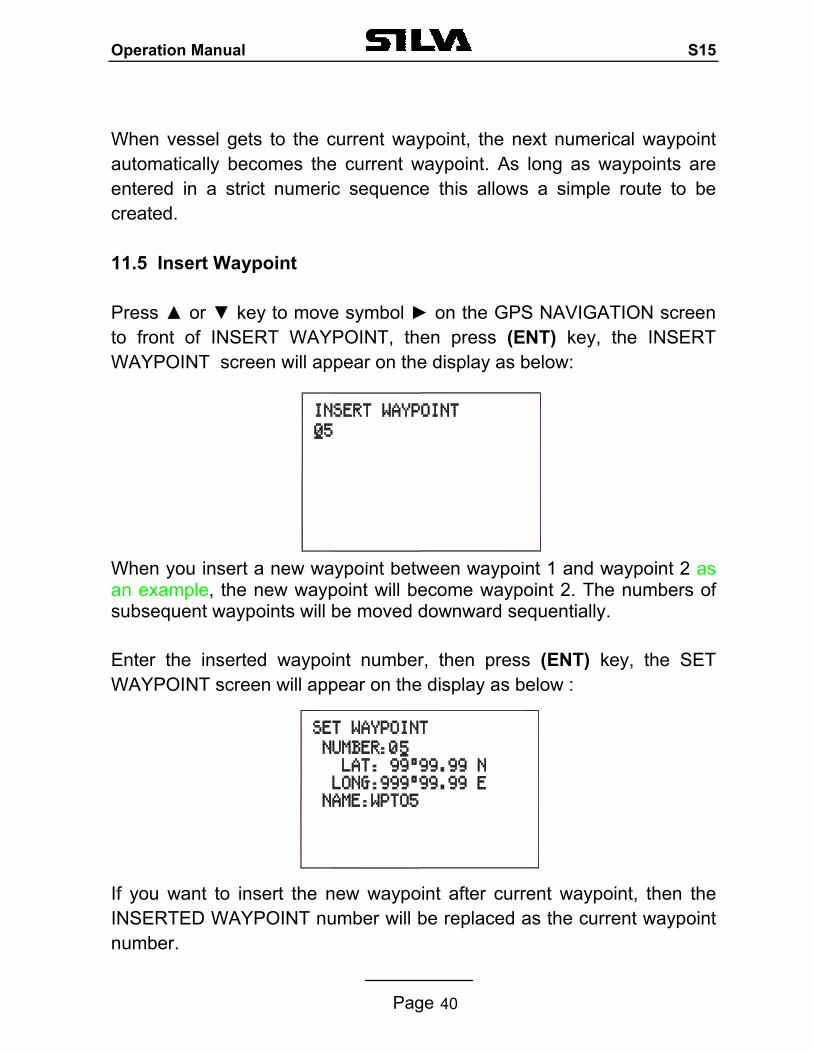
When vessel gets to the current waypoint, the next numerical waypoint automatically becomes the current waypoint. As long as waypoints are entered in a strict numeric sequence this allows a simple route to be created. 11.5 Insert Waypoint Press or key to move symbol on the GPS NAVIGATION screen to front of INSERT WAYPOINT, then press (ENT) key, the INSERT WAYPOINT screen will appear on the display as below: When you insert a new waypoint between waypoint 1 and waypoint 2 as an example, the new waypoint will become waypoint 2. The numbers of subsequent waypoints will be moved downward sequentially. Enter the inserted waypoint number, then press (ENT) key, the SET WAYPOINT screen will appear on the display as below : If you want to insert the new waypoint after current waypoint, then the INSERTED WAYPOINT number will be replaced as the current waypoint number.
Operation Manual S15
Page 41
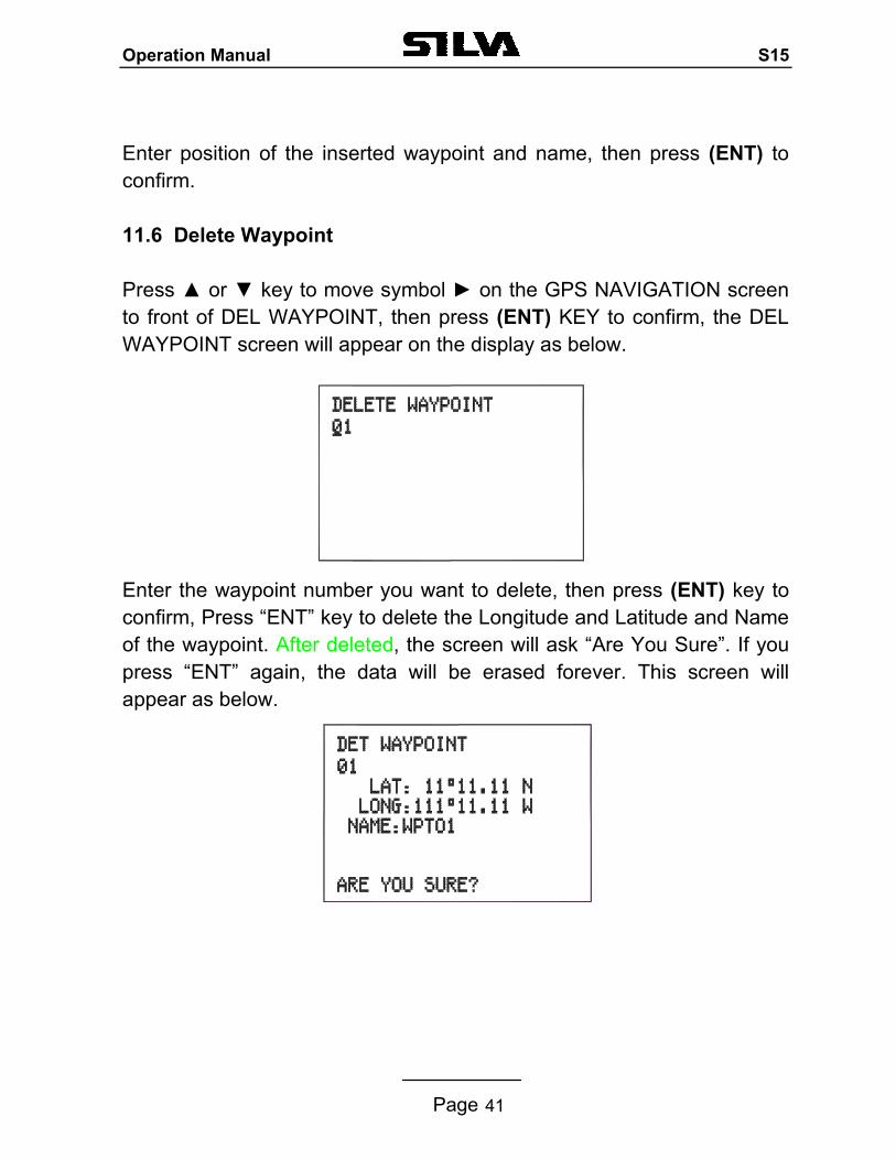
Enter position of the inserted waypoint and name, then press (ENT) to confirm. 11.6 Delete Waypoint Press or key to move symbol on the GPS NAVIGATION screen to front of DEL WAYPOINT, then press (ENT) KEY to confirm, the DEL WAYPOINT screen will appear on the display as below. Enter the waypoint number you want to delete, then press (ENT) key to confirm, Press “ENT” key to delete the Longitude and Latitude and Name of the waypoint. After deleted, the screen will ask “Are You Sure”. If you press “ENT” again, the data will be erased forever. This screen will appear as below.
Operation Manual S15
Page 42
12. Technical Specifications Power supply DC 12 V +30/-10% Channel capability 57 international channels UK: includes M1 (previously 37) and M2 Frequency Resolution 25KHz Method of frequency generation synthesizer Dimension 175(W) × 79(H) ×130(D) mm Weight 1175 grams 12.1 RECEIVER Multi Channel Receiver 1. The receiver incorporates a dual conversion super-heterodyne design. 2. Tuning frequency range 156.025-163.275MHz 3. IF frequency used: 21.4MHz; 455KHz 4. Maximum useable sensitivity ≤6dBµe.m.f. of 20dB/SINAD 5. Adjacent Channel selectivity ≥70dB 6. Spurious Response Rejection ≥70dB 7. Inter-modulation Rejection ≥68dB 8. Spurious Emission radiation 2nW 9. Current: 0.9 Amps (Max Audio) 0.3 Amps (STBY) 10. Audio Frequency Response +1, -3dB of +6dB/octave De-emphasis 300-3000Hz 11. Hum and Noise ≤40dB 12. Audio output 3.5W at less than 10% distortion with 8 Ohm external speaker 2W only internal speaker
Operation Manual S15
Page 43
12.2 CHANNEL 70 MONITOR GENERAL SPECIFICATION 1.Frequency CH70 (156.525MHz) 2.Sensitivity ≤0dBµEMF for 20dB SINAD 3.Bandwidth 16KHz 4. First IF frequency used 17.9MHz 5. Second IF frequency used 455KHz 6. Adjacent Channel Selectivity ≥70dB 7. Spurious response Rejection ≥70dB 8. Inter-modulation Rejection ≥65 dB 9. Mode of Reception 16K0G2B 10. Spurious Emission, Radiation ≤2nW, 9KHz to 2GHz 12.3 TRANSMITTER 1.Type of emission 16K0F3E(Voice) 13K5G2B(DSC) 2.Frequency range 156.025-161.425MHz 3.Output power 25W, 1W into 50 Ohms 4. Audio Harmonic Distortion ≤10% 5. Audio Frequency Response +/-3dB of +6dB/octave Pre-emphasis 300 – 3000Hz 6. Hum and Noise ≤-40dB 7. Frequency Deviation 5KHz max peak 8. Spurious Emissions (Radiated) ≤0.25µW 9. Current ≤5 Amps (25W) 12.4 NAVTEX 1.Messages stored 60 2.Input data format NAVTEX data-serial ASCII at 9600 baud, 8-bits, no
parity, stop bit without handshake. 12.5 GPS 1.Input data format: NMEA0183 version 2.0 sentences
RMC, GGA and GLL
Operation Manual S15
Page 44
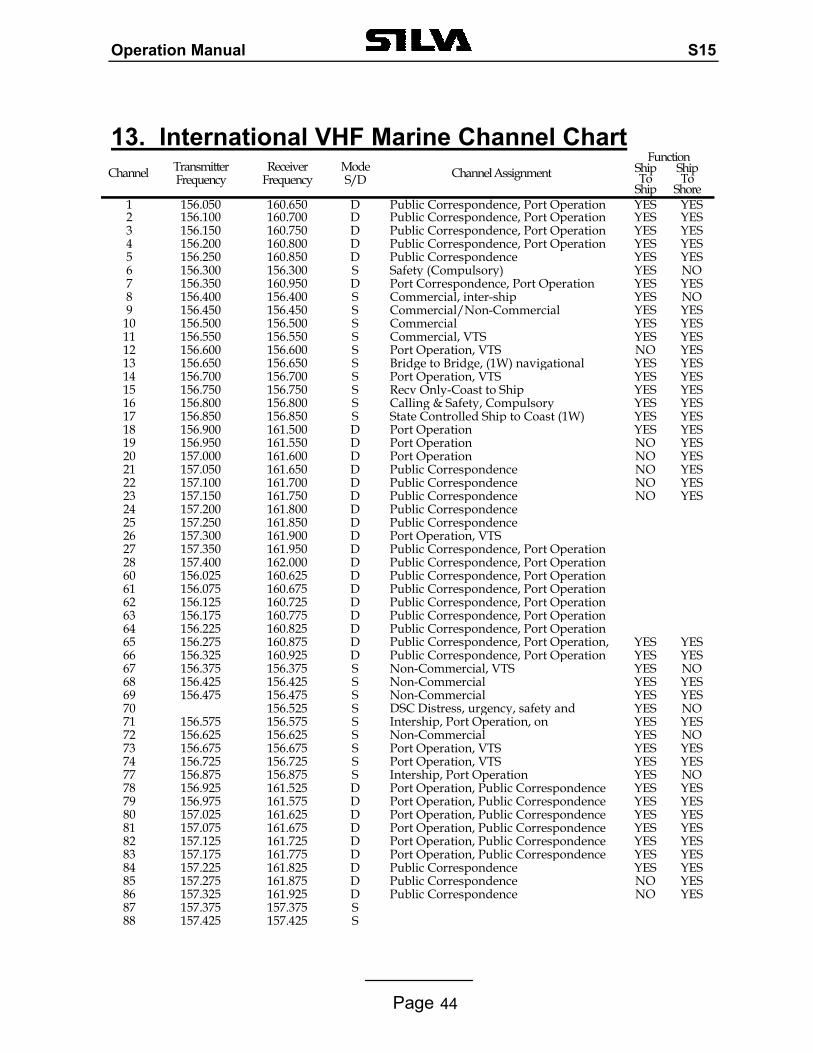
13. International VHF Marine Channel Chart
Function Channel Transmitter
Frequency Receiver
Frequency Mode S/D Channel Assignment Ship
To Ship
Ship To
Shore 1 156.050 160.650 D Public Correspondence, Port Operation YES YES 2 156.100 160.700 D Public Correspondence, Port Operation YES YES 3 156.150 160.750 D Public Correspondence, Port Operation YES YES 4 156.200 160.800 D Public Correspondence, Port Operation YES YES 5 156.250 160.850 D Public Correspondence YES YES 6 156.300 156.300 S Safety (Compulsory) YES NO 7 156.350 160.950 D Port Correspondence, Port Operation YES YES 8 156.400 156.400 S Commercial, inter-ship YES NO 9 156.450 156.450 S Commercial/Non-Commercial YES YES
10 156.500 156.500 S Commercial YES YES 11 156.550 156.550 S Commercial, VTS YES YES 12 156.600 156.600 S Port Operation, VTS NO YES 13 156.650 156.650 S Bridge to Bridge, (1W) navigational YES YES 14 156.700 156.700 S Port Operation, VTS YES YES 15 156.750 156.750 S Recv Only-Coast to Ship YES YES 16 156.800 156.800 S Calling & Safety, Compulsory YES YES 17 156.850 156.850 S State Controlled Ship to Coast (1W) YES YES 18 156.900 161.500 D Port Operation YES YES 19 156.950 161.550 D Port Operation NO YES 20 157.000 161.600 D Port Operation NO YES 21 157.050 161.650 D Public Correspondence NO YES 22 157.100 161.700 D Public Correspondence NO YES 23 157.150 161.750 D Public Correspondence NO YES 24 157.200 161.800 D Public Correspondence 25 157.250 161.850 D Public Correspondence 26 157.300 161.900 D Port Operation, VTS 27 157.350 161.950 D Public Correspondence, Port Operation 28 157.400 162.000 D Public Correspondence, Port Operation 60 156.025 160.625 D Public Correspondence, Port Operation 61 156.075 160.675 D Public Correspondence, Port Operation 62 156.125 160.725 D Public Correspondence, Port Operation 63 156.175 160.775 D Public Correspondence, Port Operation 64 156.225 160.825 D Public Correspondence, Port Operation 65 156.275 160.875 D Public Correspondence, Port Operation, YES YES 66 156.325 160.925 D Public Correspondence, Port Operation YES YES 67 156.375 156.375 S Non-Commercial, VTS YES NO 68 156.425 156.425 S Non-Commercial YES YES 69 156.475 156.475 S Non-Commercial YES YES 70 156.525 S DSC Distress, urgency, safety and YES NO 71 156.575 156.575 S Intership, Port Operation, on
lYES YES
72 156.625 156.625 S Non-Commercial YES NO 73 156.675 156.675 S Port Operation, VTS YES YES 74 156.725 156.725 S Port Operation, VTS YES YES 77 156.875 156.875 S Intership, Port Operation YES NO 78 156.925 161.525 D Port Operation, Public Correspondence YES YES 79 156.975 161.575 D Port Operation, Public Correspondence YES YES 80 157.025 161.625 D Port Operation, Public Correspondence YES YES 81 157.075 161.675 D Port Operation, Public Correspondence YES YES 82 157.125 161.725 D Port Operation, Public Correspondence YES YES 83 157.175 161.775 D Port Operation, Public Correspondence YES YES 84 157.225 161.825 D Public Correspondence YES YES 85 157.275 161.875 D Public Correspondence NO YES 86 157.325 161.925 D Public Correspondence NO YES 87 157.375 157.375 S 88 157.425 157.425 S
Operation Manual S15
Page 45
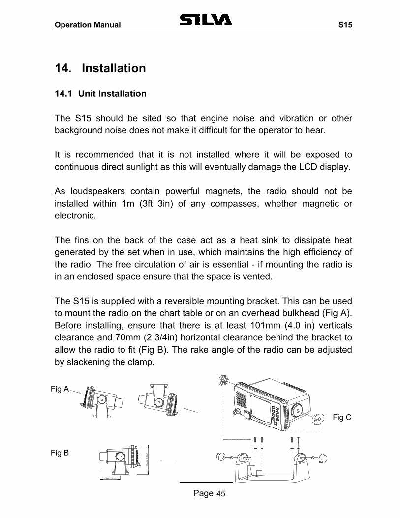
14. Installation 14.1 Unit Installation The S15 should be sited so that engine noise and vibration or other background noise does not make it difficult for the operator to hear. It is recommended that it is not installed where it will be exposed to continuous direct sunlight as this will eventually damage the LCD display. As loudspeakers contain powerful magnets, the radio should not be installed within 1m (3ft 3in) of any compasses, whether magnetic or electronic. The fins on the back of the case act as a heat sink to dissipate heat generated by the set when in use, which maintains the high efficiency of the radio. The free circulation of air is essential - if mounting the radio is in an enclosed space ensure that the space is vented. The S15 is supplied with a reversible mounting bracket. This can be used to mount the radio on the chart table or on an overhead bulkhead (Fig A). Before installing, ensure that there is at least 101mm (4.0 in) verticals clearance and 70mm (2 3/4in) horizontal clearance behind the bracket to allow the radio to fit (Fig B). The rake angle of the radio can be adjusted by slackening the clamp.
Fig C
Fig B
Fig A
Operation Manual S15
Page 46
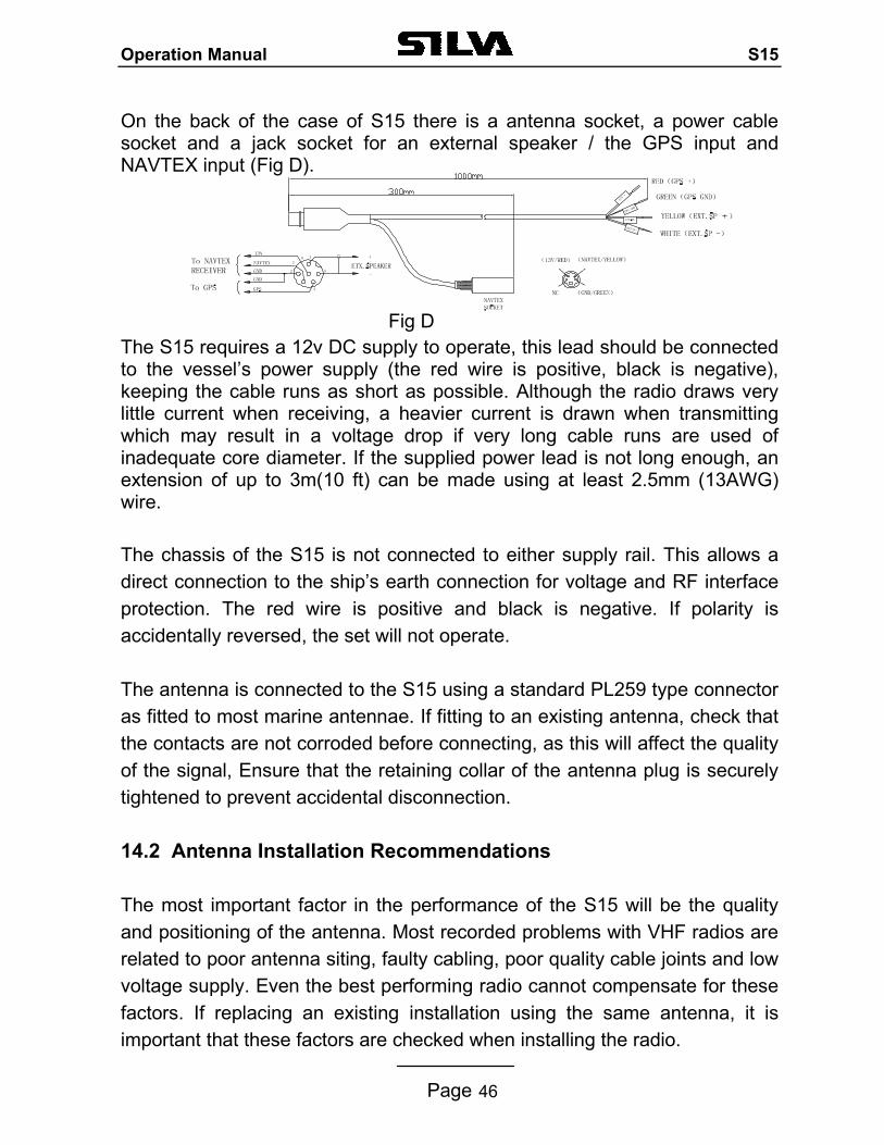
On the back of the case of S15 there is a antenna socket, a power cable socket and a jack socket for an external speaker / the GPS input and NAVTEX input (Fig D). Fig D The S15 requires a 12v DC supply to operate, this lead should be connected to the vessel’s power supply (the red wire is positive, black is negative), keeping the cable runs as short as possible. Although the radio draws very little current when receiving, a heavier current is drawn when transmitting which may result in a voltage drop if very long cable runs are used of inadequate core diameter. If the supplied power lead is not long enough, an extension of up to 3m(10 ft) can be made using at least 2.5mm (13AWG) wire. The chassis of the S15 is not connected to either supply rail. This allows a direct connection to the ship’s earth connection for voltage and RF interface protection. The red wire is positive and black is negative. If polarity is accidentally reversed, the set will not operate. The antenna is connected to the S15 using a standard PL259 type connector as fitted to most marine antennae. If fitting to an existing antenna, check that the contacts are not corroded before connecting, as this will affect the quality of the signal, Ensure that the retaining collar of the antenna plug is securely tightened to prevent accidental disconnection.
14.2 Antenna Installation Recommendations The most important factor in the performance of the S15 will be the quality and positioning of the antenna. Most recorded problems with VHF radios are related to poor antenna siting, faulty cabling, poor quality cable joints and low voltage supply. Even the best performing radio cannot compensate for these factors. If replacing an existing installation using the same antenna, it is important that these factors are checked when installing the radio.
Operation Manual S15
Page 47
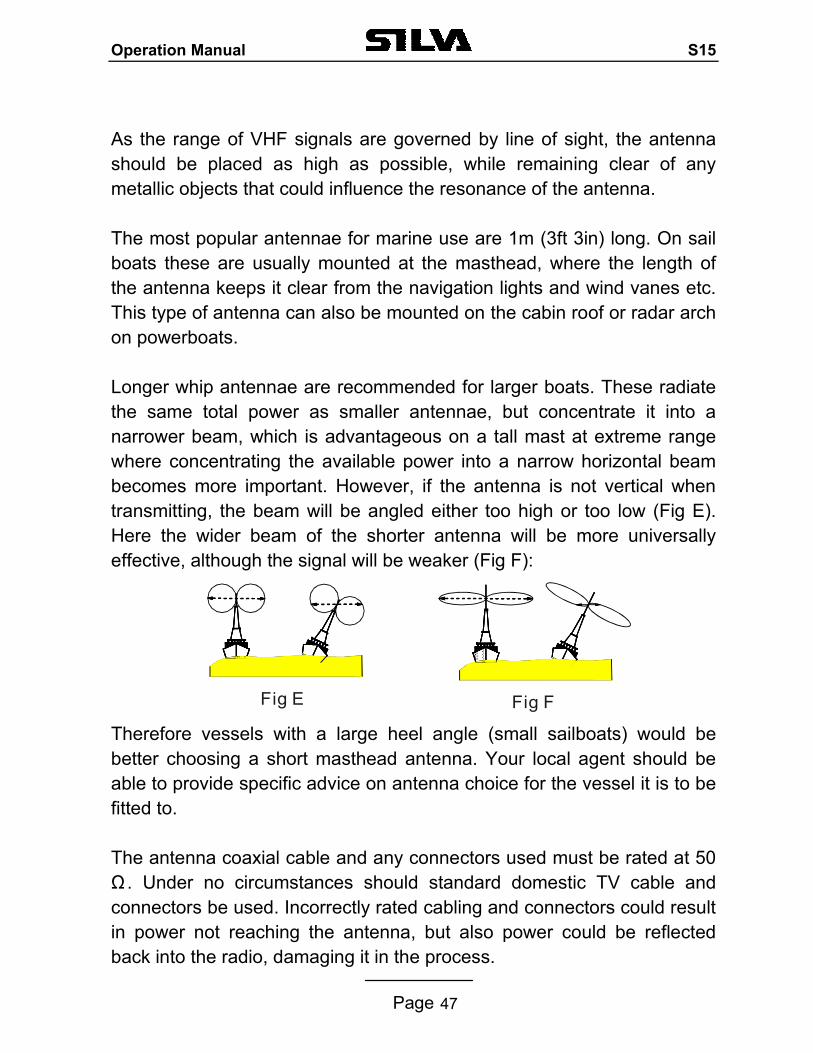
As the range of VHF signals are governed by line of sight, the antenna should be placed as high as possible, while remaining clear of any metallic objects that could influence the resonance of the antenna. The most popular antennae for marine use are 1m (3ft 3in) long. On sail boats these are usually mounted at the masthead, where the length of the antenna keeps it clear from the navigation lights and wind vanes etc. This type of antenna can also be mounted on the cabin roof or radar arch on powerboats. Longer whip antennae are recommended for larger boats. These radiate the same total power as smaller antennae, but concentrate it into a narrower beam, which is advantageous on a tall mast at extreme range where concentrating the available power into a narrow horizontal beam becomes more important. However, if the antenna is not vertical when transmitting, the beam will be angled either too high or too low (Fig E). Here the wider beam of the shorter antenna will be more universally effective, although the signal will be weaker (Fig F): Therefore vessels with a large heel angle (small sailboats) would be better choosing a short masthead antenna. Your local agent should be able to provide specific advice on antenna choice for the vessel it is to be fitted to. The antenna coaxial cable and any connectors used must be rated at 50Ω . Under no circumstances should standard domestic TV cable and connectors be used. Incorrectly rated cabling and connectors could result in power not reaching the antenna, but also power could be reflected back into the radio, damaging it in the process.
Fig FFig E
Operation Manual S15
Page 48
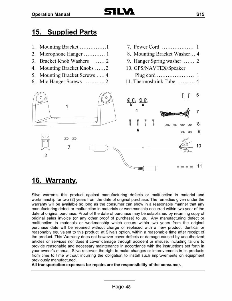
15. Supplied Parts
1. Mounting Bracket ……………1 7. Power Cord ……………… 1 2. Microphone Hanger ………… 1 8. Mounting Bracket Washer… 4 3. Bracket Knob Washers …… 2 9. Hanger Spring washer …… 2 4. Mounting Bracket Knobs …… 2 10. GPS/NAVTEX/Speaker 5. Mounting Bracket Screws ……4 Plug cord ………………… 1 6. Mic Hanger Screws ………...2 11. Thermoshrink Tube ……… 4
16. Warranty. Silva warrants this product against manufacturing defects or malfunction in material and workmanship for two (2) years from the date of original purchase. The remedies given under the warranty will be available so long as the consumer can show in a reasonable manner that any manufacturing defect or malfunction in materials or workmanship occurred within two year of the date of original purchase. Proof of the date of purchase may be established by returning copy of original sales invoice (or any other proof of purchase) to us. Any manufacturing defect or malfunction in materials or workmanship which occurs within two years from the original purchase date will be repaired without charge or replaced with a new product identical or reasonably equivalent to this product, at Silva’s option, within a reasonable time after receipt of the product. This Warranty does not however cover defects or damage caused by unauthorized articles or services nor does it cover damage through accident or misuse, including failure to provide reasonable and necessary maintenance in accordance with the instructions set forth in your owner’s manual. Silva reserves the right to make changes or improvements in its products from time to time without incurring the obligation to install such improvements on equipment previously manufactured. All transportation expenses for repairs are the responsibility of the consumer.
1
2
3
6
8 5
74
9
10
11
Operation Manual S15
Page 49
17. Declaration of Conformity
We Silva UK Ltd. of Fleming Road,
Kirkton Campus, Livingston,
EH54 7BN, SCOTLAND.
declare that the product identified below complies with the essential requirements of Council Directive 99/05/EC according to the conformity assessment procedure laid down in Annex IV of the Directive.
QINETIQ statement of opinion: QQ-RTTE 22/02-01
Product:
Silva S15
25 Watt Marine Band Class D Transceiver.
For non-compulsory fit use only.
The product is labelled with the CE conformity marking and the identification number of the notified body consulted in the conformity assessment procedure.
Applicable Standards: EN301-025
EN60945:1997 (clauses 9, 10 & 12).
ETS 300-225:1992
Livingston, 1st December 20002.
Mr A. Kent. Managing Director

Operation Manual S15
Page 50
0191