Embed Size (px)
Citation preview
VHDL
IE- CSE
What do you understand by VHDL?? VHDL stands for VHSIC (Very High
Speed Integrated Circuits) Hardware Description Language
What are Integrated Circuits??
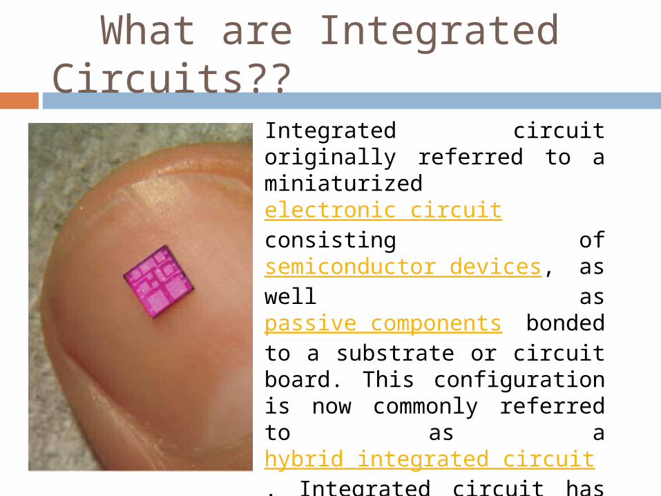
Integrated circuit originally referred to a miniaturized electronic circuit consisting of semiconductor devices, as well as passive components bonded to a substrate or circuit board. This configuration is now commonly referred to as a hybrid integrated circuit. Integrated circuit has since come to refer to the single-piece circuit construction originally known as a monolithic integrated circuit.
APPLICATION AND PURPOSE
VHDL is for writing models of a system• Reasons for modelling– requirements specification– documentation– testing using simulation– formal verification– synthesis• Goal– most reliable design process, with minimum
cost andtime– avoid design errors!
Difference between a VHDL and other programming languages A hardware description language is
inherently parallel, i.e. commands, which correspond to logic gates, are executed (computed) in parallel, as soon as a new input arrives. A HDL program mimics the behaviour of a physical, usually digital, system. It also allows incorporation of timing specifications (gate delays) as well as to describe a system as an interconnection of different components.
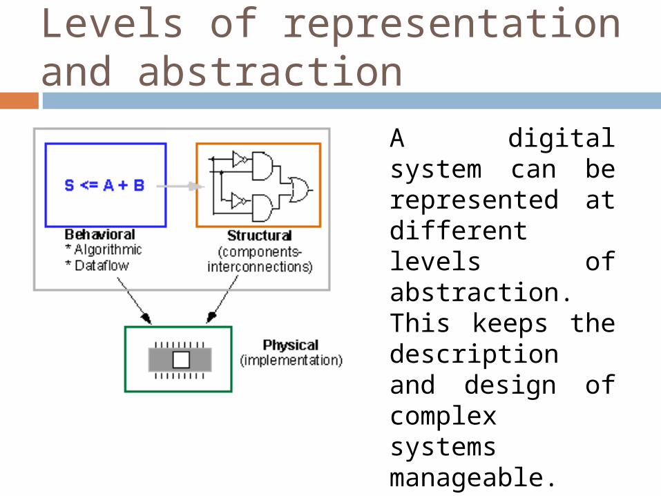
Levels of representation and abstraction
A digital system can be represented at different levels of abstraction. This keeps the description and design of complex systems manageable. Figure shows different levels of abstraction.
BEHAVIOURAL
The highest level of abstraction is the behavioural level that describes a system in terms of what it does (or how it behaves) rather than in terms of its components and interconnection between them. A behavioural description specifies the relationship between the input and output signals. This could be a Boolean expression or a more abstract description such as an algorithm.
Example:- Warning = IgnitionOn AND ( DoorOpen OR SeatbeltOff)
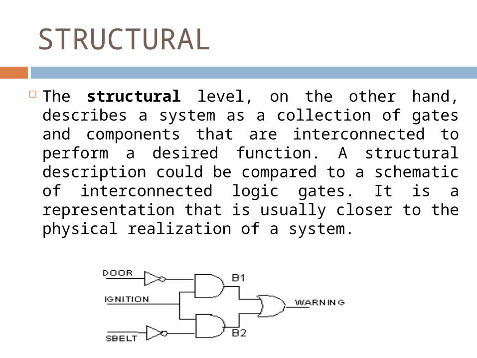
STRUCTURAL
The structural level, on the other hand, describes a system as a collection of gates and components that are interconnected to perform a desired function. A structural description could be compared to a schematic of interconnected logic gates. It is a representation that is usually closer to the physical realization of a system.
STRUCTURAL AND BEHAVIORAL IN VHDL VHDL allows one to describe a digital
system at the structural or the behavioural level. The behavioural level can be further divided into two kinds of styles: Data flow and Algorithmic. The dataflow representation describes how data moves through the system. This is typically done in terms of data flow between registers
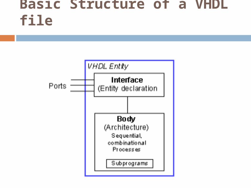
Basic Structure of a VHDL file
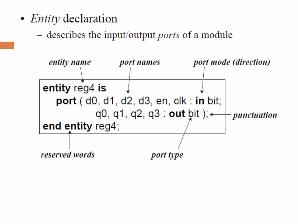
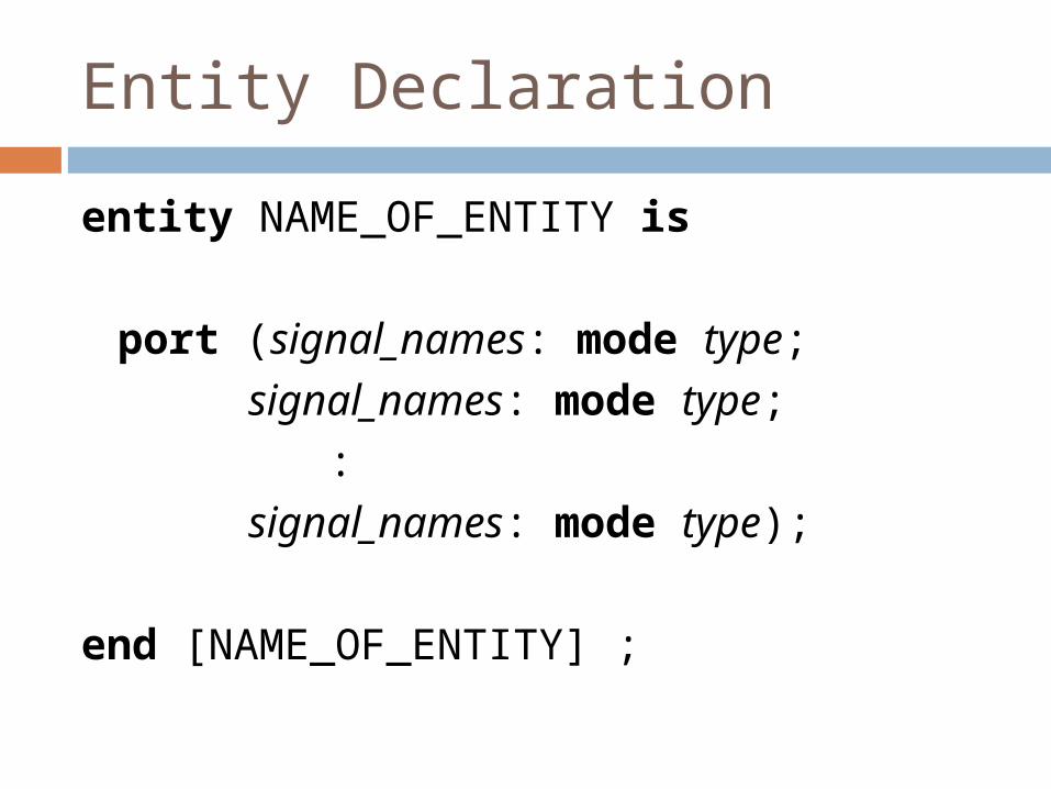
Entity Declaration
entity NAME_OF_ENTITY is
port (signal_names: mode type; signal_names: mode type;
: signal_names: mode type);
end [NAME_OF_ENTITY] ;
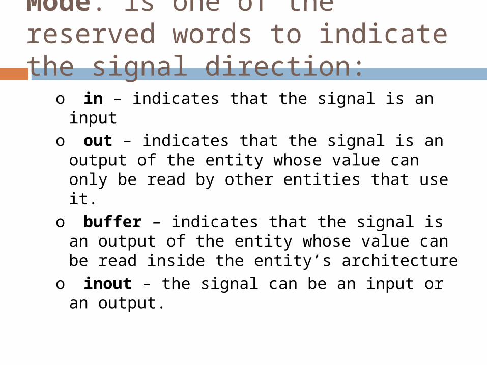
Mode: is one of the reserved words to indicate the signal direction:
o in – indicates that the signal is an inputo out – indicates that the signal is an output
of the entity whose value can only be read by other entities that use it.
o buffer – indicates that the signal is an output of the entity whose value can be read inside the entity’s architecture
o inout – the signal can be an input or an output.
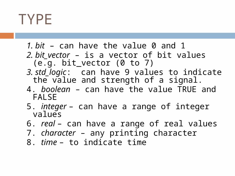
TYPE
1. bit – can have the value 0 and 12. bit_vector – is a vector of bit values
(e.g. bit_vector (0 to 7)3. std_logic: can have 9 values to indicate
the value and strength of a signal.4. boolean – can have the value TRUE and
FALSE5. integer – can have a range of integer
values6. real – can have a range of real values7. character – any printing character8. time – to indicate time
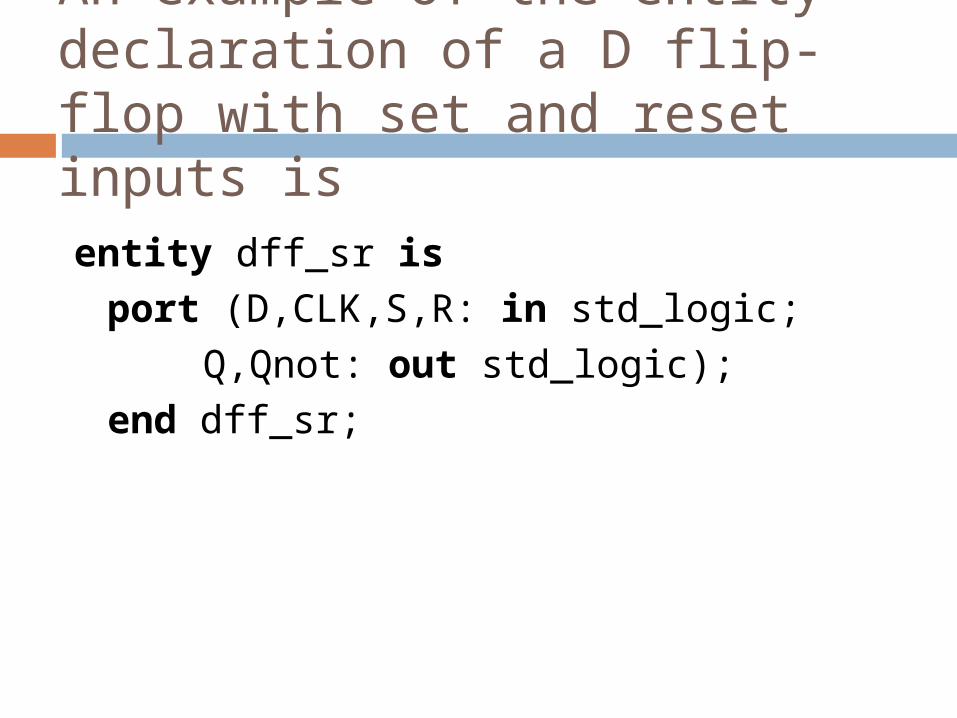
An example of the entity declaration of a D flip-flop with set and reset inputs is entity dff_sr is
port (D,CLK,S,R: in std_logic;Q,Qnot: out std_logic );
end dff_sr;
Architecture body
Architecture body– describes an implementation of an entity– may be several per entity
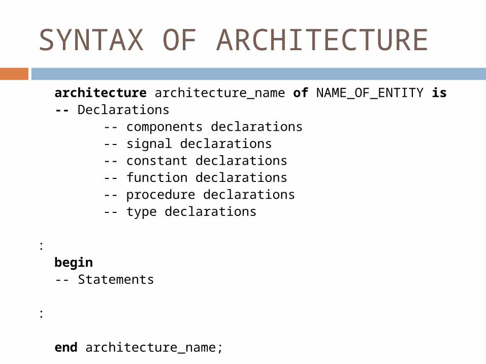
SYNTAX OF ARCHITECTURE
architecture architecture_name of NAME_OF_ENTITY is-- Declarations
-- components declarations-- signal declarations-- constant declarations-- function declarations-- procedure declarations-- type declarations
: begin
-- Statements
:
end architecture_name;
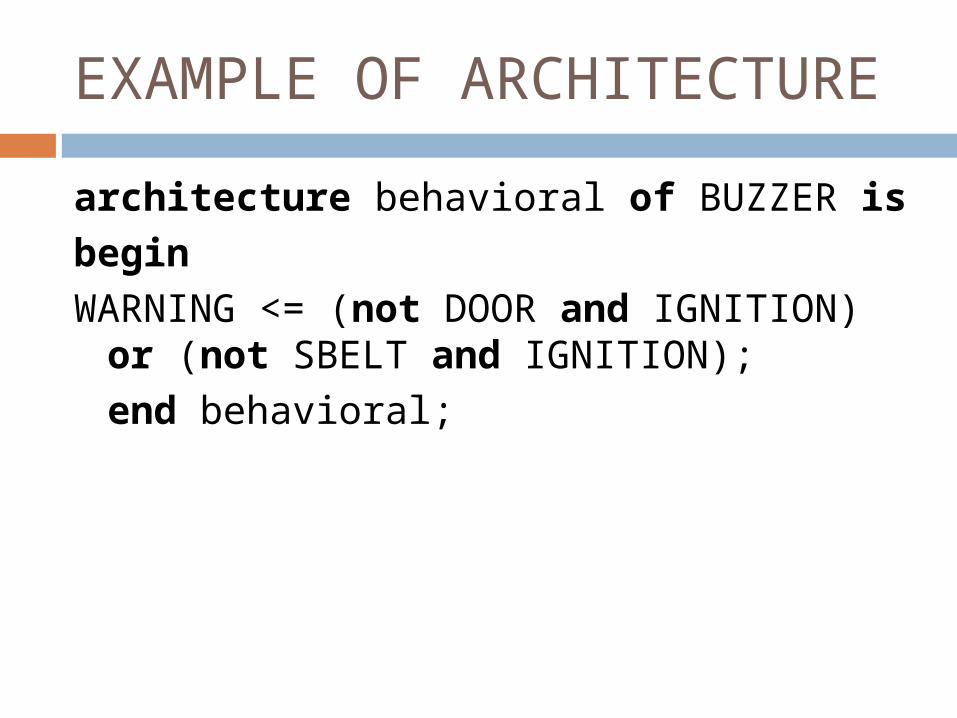
EXAMPLE OF ARCHITECTUREarchitecture behavioral of BUZZER isbeginWARNING <= (not DOOR and IGNITION)
or (not SBELT and IGNITION);end behavioral;
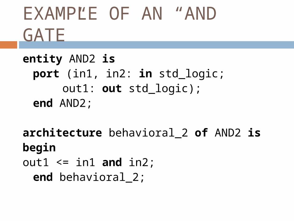
EXAMPLE OF AN “AND GATE”entity AND2 is
port (in1, in2: in std_logic;out1: out std_logic);
end AND2; architecture behavioral_2 of AND2 isbeginout1 <= in1 and in2;
end behavioral_2;
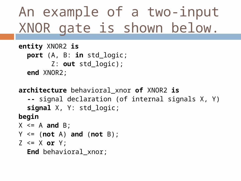
An example of a two-input XNOR gate is shown below.entity XNOR2 is
port (A, B: in std_logic;Z: out std_logic);
end XNOR2; architecture behavioral_xnor of XNOR2 is
-- signal declaration (of internal signals X, Y)signal X, Y: std_logic;
beginX <= A and B;Y <= (not A) and (not B);Z <= X or Y;
End behavioral_xnor;
Concurrency
It is worth pointing out that the signal assignments in the above examples are concurrent statements. This implies that the statements are executed when one or more of the signals on the right hand side change their value (i.e. an event occurs on one of the signals). For instance, when the input A changes, the internal signals X and Y change values that in turn causes the last statement to update the output Z. There may be a propagation delay associated with this change.
Modelling Structure
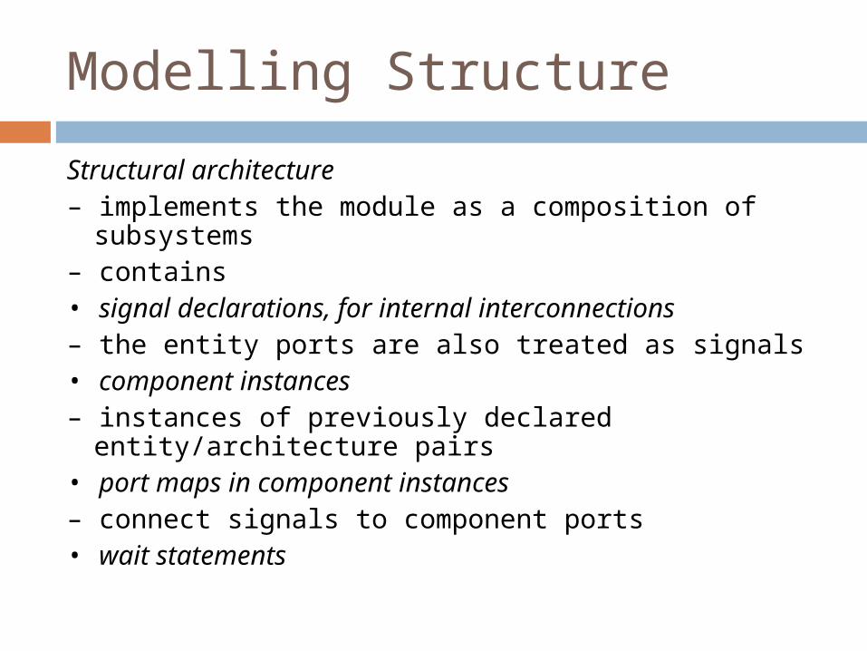
Structural architecture– implements the module as a composition of
subsystems– contains• signal declarations, for internal interconnections– the entity ports are also treated as signals• component instances– instances of previously declared entity/architecture
pairs• port maps in component instances– connect signals to component ports• wait statements
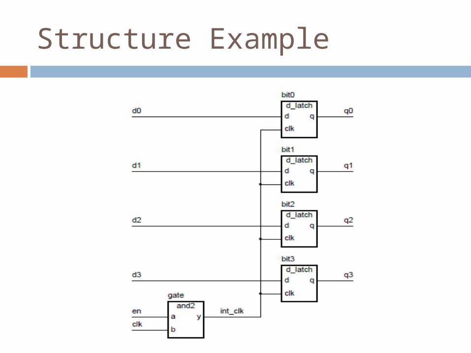
Structure Example
COMPONENTS
VHDL can’t directly instantiate entity/architecture pair
Instead
– include component declarations in structural architecture body
- templates for entity declarations
– instantiate components
– write a configuration declaration
-binds entity/architecture pair to each instantiated
component
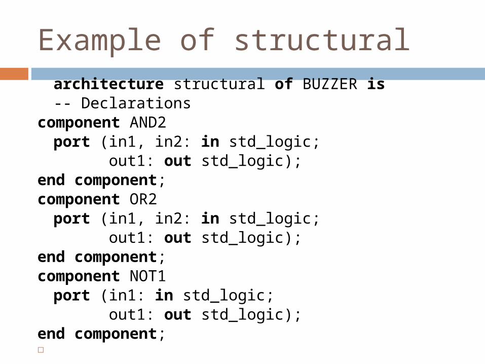
Example of structural architecture structural of BUZZER is
-- Declarationscomponent AND2
port (in1, in2: in std_logic; out1: out std_logic);
end component;component OR2
port (in1, in2: in std_logic; out1: out std_logic);
end component;component NOT1
port (in1: in std_logic; out1: out std_logic);
end component;
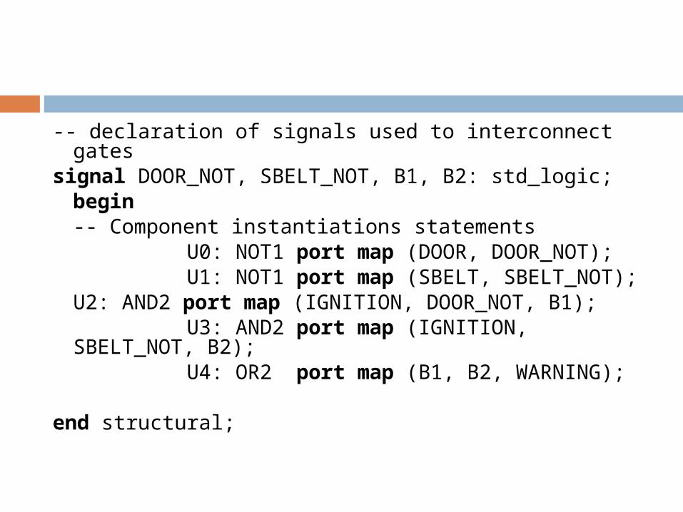
-- declaration of signals used to interconnect gatessignal DOOR_NOT, SBELT_NOT, B1, B2: std_logic;
begin -- Component instantiations statements
U0: NOT1 port map (DOOR, DOOR_NOT); U1: NOT1 port map (SBELT, SBELT_NOT);
U2: AND2 port map (IGNITION, DOOR_NOT, B1);
U3: AND2 port map (IGNITION, SBELT_NOT, B2);
U4: OR2 port map (B1, B2, WARNING); end structural;
IMPORTANT
In our example, we use a two- input AND gate, two input OR gate and an inverter. These gates have to be defined first, i.e. they will need an entity declaration and architecture body.
DAY 3
‘EVENT
clk'event : represents every clock events (i.e) at every cycle
clk=1 : do the function when clk =1, its represent the rising edge.
Rising_edge(<identifier>)
Returns "TRUE" only when the present value is '1' and the last value is '0'.If the past value is something like 'Z','U' etc. then it will return a "FALSE" value. This makes the code, bug free, because the function returns only valid clock transitions ,that means '0' to '1'.All the rules and examples said above equally apply to falling_edge() function also.
GENERICS-SIGNIFICANCE
Generics are used for quickly modifying the code as and when required.
Designers use generics so that they can change the design quickly on clients/customers request.

GENERICS
Syntax:
<generic_name>: type [:= <initial_value>];
Examples:
bus_width: integer := 8;my_boolean: boolean := false;
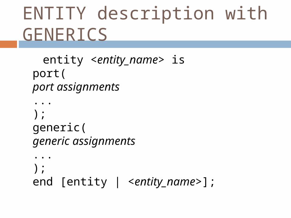
ENTITY description with GENERICS entity <entity_name> is
port(port assignments...);generic(generic assignments...);end [entity | <entity_name>];
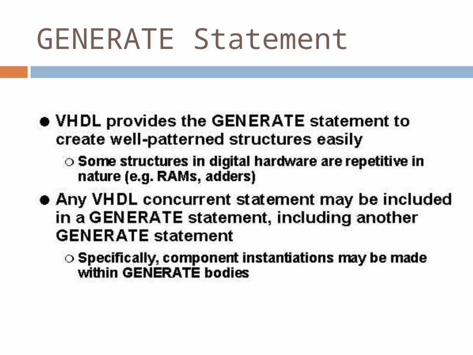
GENERATE Statement
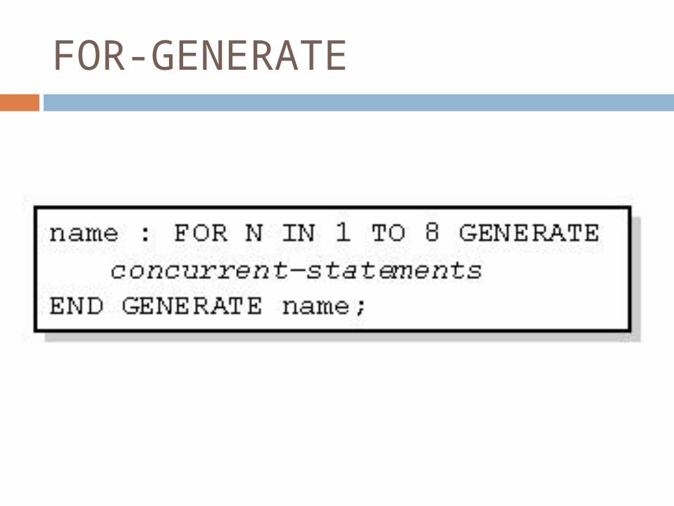
FOR-GENERATE
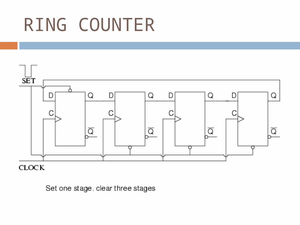
RING COUNTER
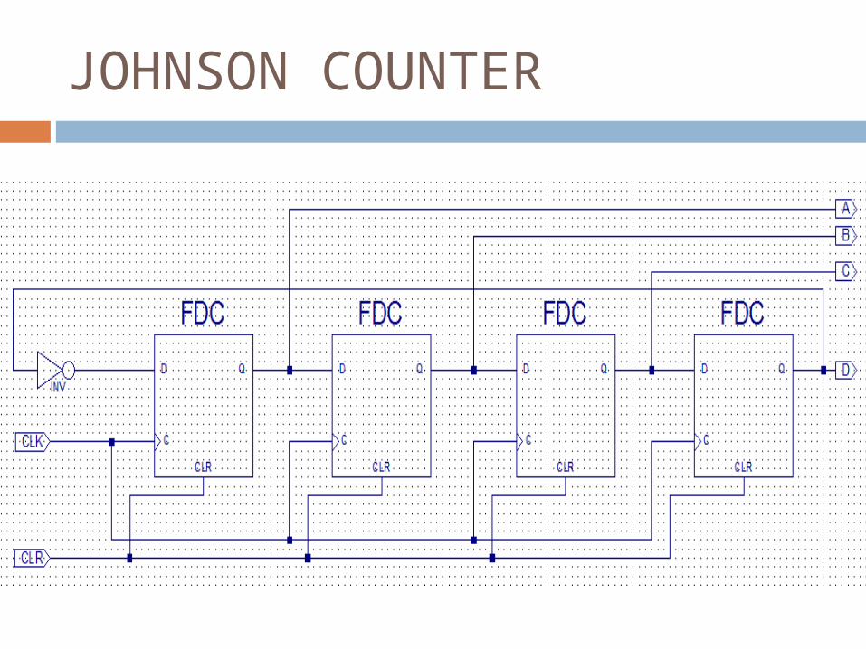
JOHNSON COUNTER
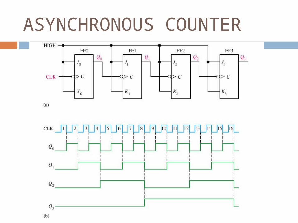
ASYNCHRONOUS COUNTER
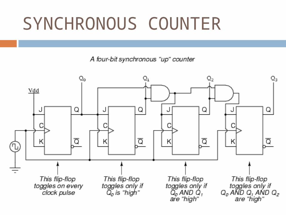
SYNCHRONOUS COUNTER
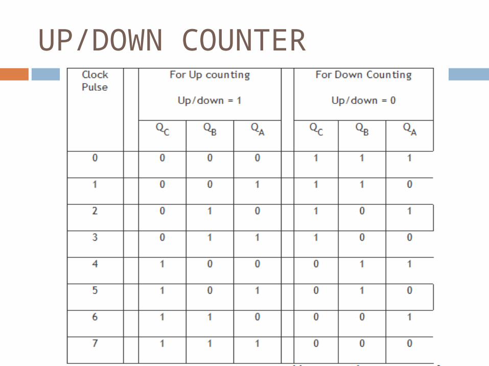
UP/DOWN COUNTER
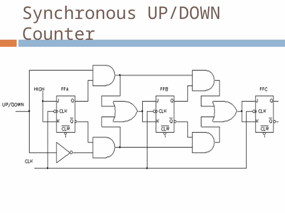
Synchronous UP/DOWN Counter
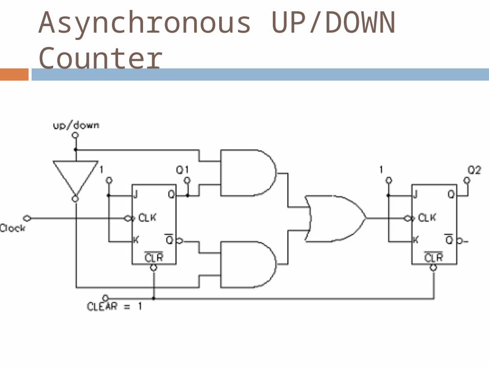
Asynchronous UP/DOWN Counter

THANK YOU