Embed Size (px)
Citation preview
44 High Frequency Electronics
High Frequency Products
HARMONIC BALANCE
VHDL-AMS Extensions Enable RF Harmonic Balance Simulation
By Mark RencherRidgetop Group, Inc.
VHDL-AMS/FD isthe extension lan-guage that sup-
ports harmonic balancesimulation for frequencydomain analysis. This fre-quency domain (FD) lan-guage extension providesthe RF designer the capa-
bility to describe a wireless system from archi-tecture to transistors. The use of harmonicbalance overcomes both of the limitationsfound in the shooting or SpectreRF approach-es. Neither different time constants nor com-plex frequency-dependent passive componentsimpact the technique’s ability to accuratelysolve circuit equations and provide meaning-ful results.
harmonic balance (HB) is most useful inthe analysis of components or systems thatinvolve intermodulation distortions (IMD)and/or frequency conversion. Examples in-clude mixer IMD with closely spaced tones,power amplifiers, load-pull, frequency multi-pliers, steady-state response of oscillators, andsystem simulation.
Harmonic BalanceRFICs typically include frequency up-
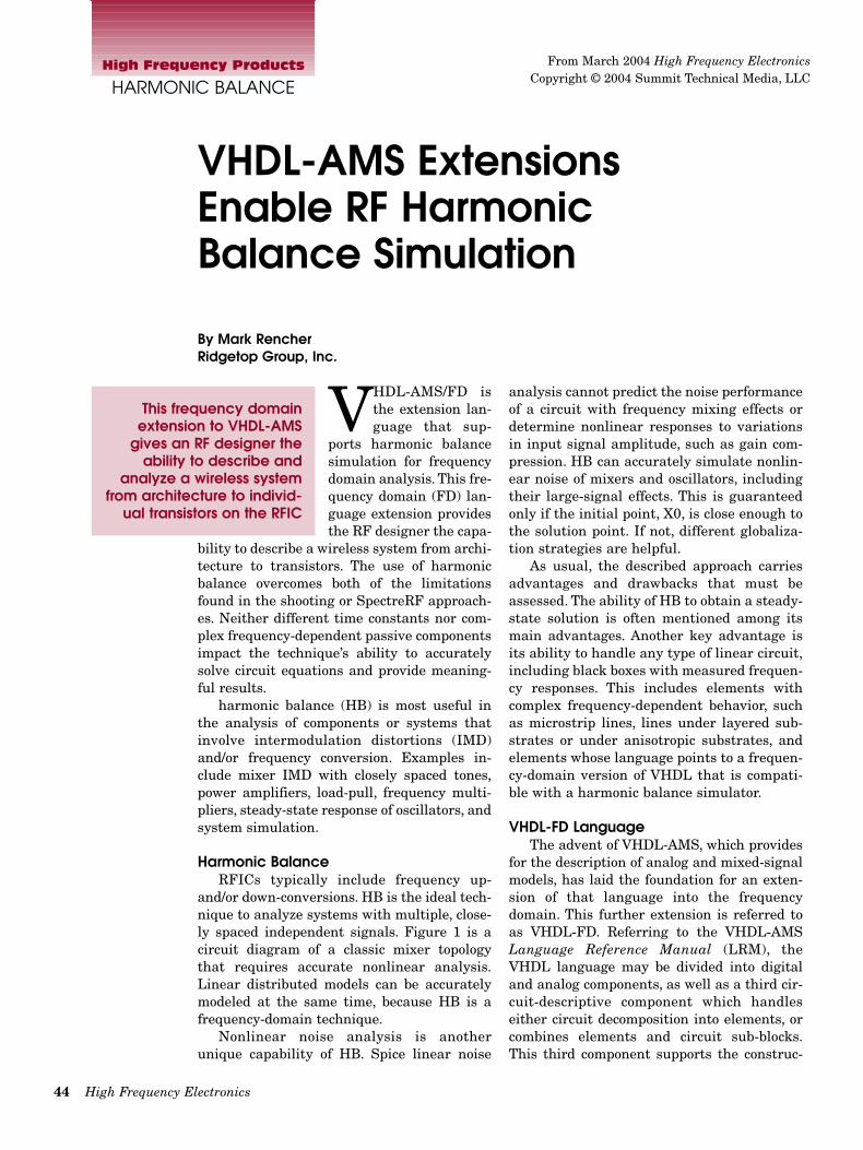
and/or down-conversions. HB is the ideal tech-nique to analyze systems with multiple, close-ly spaced independent signals. Figure 1 is acircuit diagram of a classic mixer topologythat requires accurate nonlinear analysis.Linear distributed models can be accuratelymodeled at the same time, because HB is afrequency-domain technique.
Nonlinear noise analysis is anotherunique capability of HB. Spice linear noise
analysis cannot predict the noise performanceof a circuit with frequency mixing effects ordetermine nonlinear responses to variationsin input signal amplitude, such as gain com-pression. HB can accurately simulate nonlin-ear noise of mixers and oscillators, includingtheir large-signal effects. This is guaranteedonly if the initial point, X0, is close enough tothe solution point. If not, different globaliza-tion strategies are helpful.
As usual, the described approach carriesadvantages and drawbacks that must beassessed. The ability of HB to obtain a steady-state solution is often mentioned among itsmain advantages. Another key advantage isits ability to handle any type of linear circuit,including black boxes with measured frequen-cy responses. This includes elements withcomplex frequency-dependent behavior, suchas microstrip lines, lines under layered sub-strates or under anisotropic substrates, andelements whose language points to a frequen-cy-domain version of VHDL that is compati-ble with a harmonic balance simulator.
VHDL-FD LanguageThe advent of VHDL-AMS, which provides
for the description of analog and mixed-signalmodels, has laid the foundation for an exten-sion of that language into the frequencydomain. This further extension is referred toas VHDL-FD. Referring to the VHDL-AMSLanguage Reference Manual (LRM), theVHDL language may be divided into digitaland analog components, as well as a third cir-cuit-descriptive component which handleseither circuit decomposition into elements, orcombines elements and circuit sub-blocks.This third component supports the construc-
This frequency domainextension to VHDL-AMS
gives an RF designer theability to describe and
analyze a wireless systemfrom architecture to individ-
ual transistors on the RFIC
From March 2004 High Frequency ElectronicsCopyright © 2004 Summit Technical Media, LLC
March 2004 45
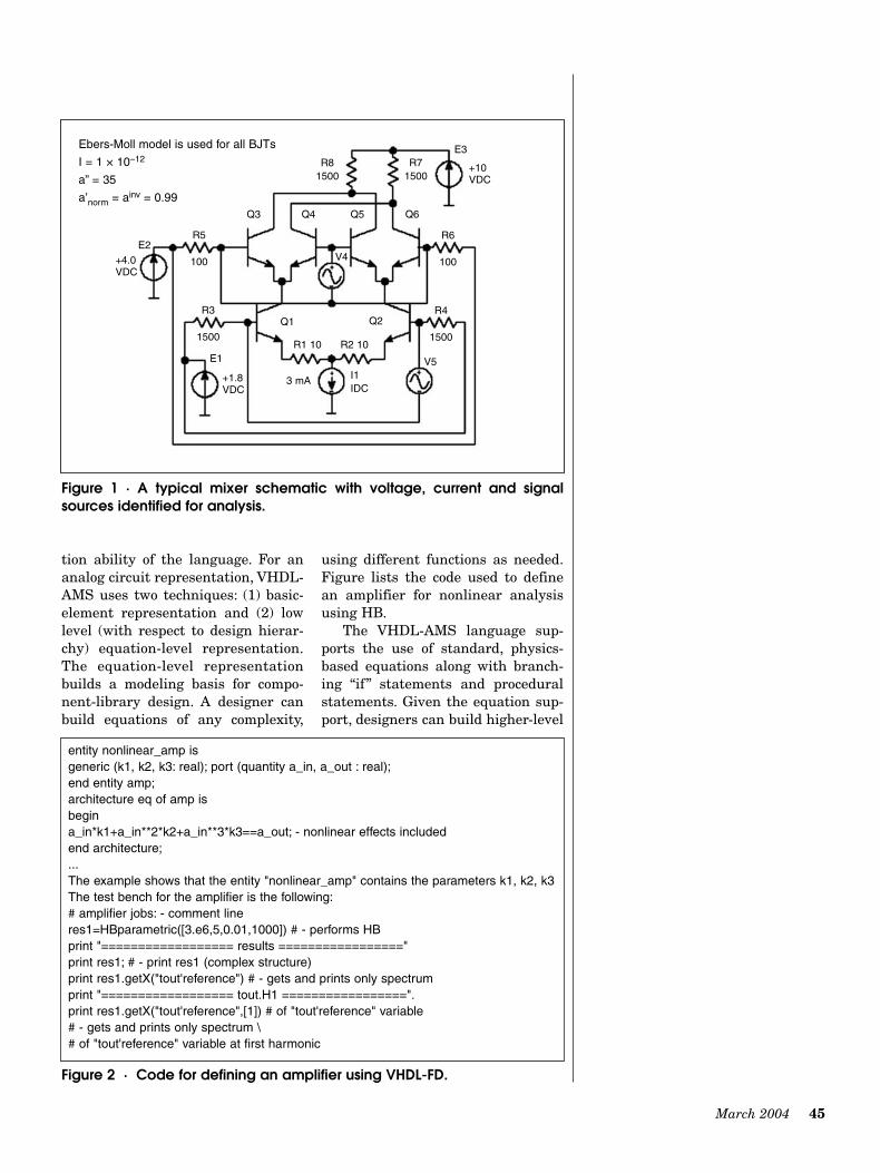
tion ability of the language. For ananalog circuit representation, VHDL-AMS uses two techniques: (1) basic-element representation and (2) lowlevel (with respect to design hierar-chy) equation-level representation.The equation-level representationbuilds a modeling basis for compo-nent-library design. A designer canbuild equations of any complexity,
using different functions as needed.Figure lists the code used to definean amplifier for nonlinear analysisusing HB.
The VHDL-AMS language sup-ports the use of standard, physics-based equations along with branch-ing “if” statements and proceduralstatements. Given the equation sup-port, designers can build higher-level
Figure 1 · A typical mixer schematic with voltage, current and signalsources identified for analysis.
Ebers-Moll model is used for all BJTs
I = 1 × 10–12
a” = 35
a’norm = ainv = 0.99
+4.0VDC
+10VDC
+1.8VDC
I1IDC
3 mA
E2
Q3
Q1 Q2
Q4
V4
V5
Q5 Q6
E3
E1
R5
100
R6
100
R3
1500
R81500
R1 10 R2 10
R71500
R4
1500
entity nonlinear_amp isgeneric (k1, k2, k3: real); port (quantity a_in, a_out : real);end entity amp;architecture eq of amp isbegina_in*k1+a_in**2*k2+a_in**3*k3==a_out; - nonlinear effects includedend architecture;...The example shows that the entity "nonlinear_amp" contains the parameters k1, k2, k3 The test bench for the amplifier is the following:# amplifier jobs: - comment lineres1=HBparametric([3.e6,5,0.01,1000]) # - performs HBprint "================== results ================="print res1; # - print res1 (complex structure)print res1.getX("tout'reference") # - gets and prints only spectrumprint "================== tout.H1 =================".print res1.getX("tout'reference",[1]) # of "tout'reference" variable# - gets and prints only spectrum \# of "tout'reference" variable at first harmonic
Figure 2 · Code for defining an amplifier using VHDL-FD.
46 High Frequency Electronics
High Frequency Products
HARMONIC BALANCE
blocks and connect them to create more complex struc-tures. Two approaches are available for this: making con-nections using “quantities” and making connectionsthrough “terminals.” Quantities are standard variables inthe scope of VHDL-AMS. Several blocks can share thesame variables, and connection via quantities. It is conve-nient to describe signal-flow diagrams and simple closedsystems using quantities.
Terminals carry out additional work. They assume thepreservation of conservation laws—such as Kirchoff ’slaws—in electrical engineering. Terminals contain twoquantities: an “across” variable and a “through” variable.The “across” quantity acts like the voltage at a node orbranch and the “through” quantity acts like the incidentcurrent of the node. Another useful feature of the behav-ioral approach is that it is multidisciplinary. It is possibleto describe and simulate mixed systems, such as elec-tromechanical, electrohydraulic, and laser systems, usingthis approach. These extremely useful characteristicsprovide a significant inducement to use VHDL-AMS asthe basic language for adaptation in the microwavedesign realm, as a frequency domain form (VHDL-FD).
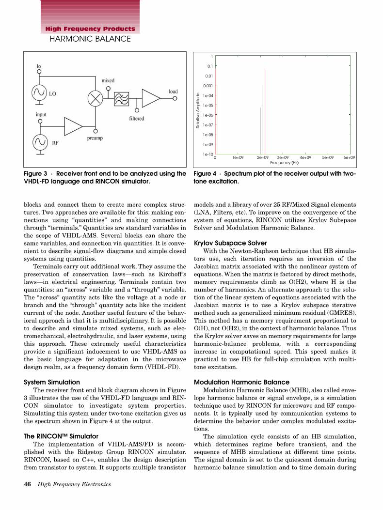
System SimulationThe receiver front end block diagram shown in Figure
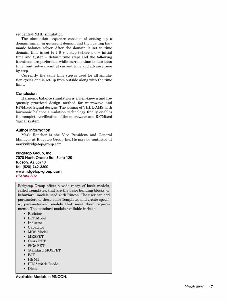
3 illustrates the use of the VHDL-FD language and RIN-CON simulator to investigate system properties.Simulating this system under two-tone excitation gives usthe spectrum shown in Figure 4 at the output.
The RINCON™ SimulatorThe implementation of VHDL-AMS/FD is accom-
plished with the Ridgetop Group RINCON simulator.RINCON, based on C++, enables the design descriptionfrom transistor to system. It supports multiple transistor
models and a library of over 25 RF/Mixed Signal elements(LNA, Filters, etc). To improve on the convergence of thesystem of equations, RINCON utilizes Krylov SubspaceSolver and Modulation Harmonic Balance.
Krylov Subspace Solver With the Newton-Raphson technique that HB simula-
tors use, each iteration requires an inversion of theJacobian matrix associated with the nonlinear system ofequations. When the matrix is factored by direct methods,memory requirements climb as O(H2), where H is thenumber of harmonics. An alternate approach to the solu-tion of the linear system of equations associated with theJacobian matrix is to use a Krylov subspace iterativemethod such as generalized minimum residual (GMRES).This method has a memory requirement proportional toO(H), not O(H2), in the context of harmonic balance. Thusthe Krylov solver saves on memory requirements for largeharmonic-balance problems, with a correspondingincrease in computational speed. This speed makes itpractical to use HB for full-chip simulation with multi-tone excitation.
Modulation Harmonic BalanceModulation Harmonic Balance (MHB), also called enve-
lope harmonic balance or signal envelope, is a simulationtechnique used by RINCON for microwave and RF compo-nents. It is typically used by communication systems todetermine the behavior under complex modulated excita-tions.
The simulation cycle consists of an HB simulation,which determines regime before transient, and thesequence of MHB simulations at different time points.The signal domain is set to the quiescent domain duringharmonic balance simulation and to time domain during
Figure 3 · Receiver front end to be analyzed using theVHDL-FD language and RINCON simulator.
Figure 4 · Spectrum plot of the receiver output with two-tone excitation.
0 1e+09 2e+09 3e+09 4e+09 5e+09 6e+09Frequency (Hz)
1
0.1
0.01
0.001
1e-04
1e-05
1e-06
1e-07
1e-08
1e-09
1e-10
Re
lativ
e A
mp
litu
de
March 2004 47
sequential MHB simulation.The simulation sequence consists of setting up a
domain signal in quiescent domain and then calling har-monic balance solver. After the domain is set to timedomain, time is set to t_0 + t_step (where t_0 = initialtime and t_step = default time step) and the followingiterations are performed while current time is less thantime limit: solve circuit at current time and advance timeby step.
Currently, the same time step is used for all simula-tion cycles and is set up from outside along with the timelimit.
ConclusionHarmonic balance simulation is a well-known and fre-
quently practiced design method for microwave andRF/Mixed Signal designs. The joining of VHDL-AMS withharmonic balance simulation technology finally enablesthe complete verification of the microwave and RF/MixedSignal system.
Author InformationMark Rencher is the Vice President and General
Manager at Ridgetop Group Inc. He may be contacted [email protected]
Ridgetop Group, Inc. 7070 North Oracle Rd., Suite 120Tucson, AZ 85740Tel: (520) 742-3300www.ridgetop-group.comHFeLink 302
Ridgetop Group offers a wide range of basic models,called Templates, that are the basic building blocks, orbehavioral models used with Rincon. The user can addparameters to these basic Templates and create specif-ic, parameterized models that meet their require-ments. The standard models available include:
• Resistor• BJT Model• Inductor• Capacitor• MOS Model• MESFET• GaAs FET• SiGe FET• Standard MOSFET• BJT• HEMT• PIN Switch Diode• Diode
Available Models in RINCON.


![VHDL-AMS based modeling and simulation of mixed …technology problems is VHDL-AMS [6–8]. This high-level hardware description language is an IEEE standard and extension of a digital](https://img.pdfslide.us/doc/110x75/5e4e0bacbd0d724aef12c29f/vhdl-ams-based-modeling-and-simulation-of-mixed-technology-problems-is-vhdl-ams.jpg)
![ATA6560 - CAN Transceiver VHDL-AMS Model (Level 2)ww1.microchip.com/...9396_ATA6560-CAN-Transceiver-VHDL-AMS-M… · ATAN0132 [APPLICATION NOTE] 3 9396A–AUTO–06/15 1. Implementation](https://img.pdfslide.us/doc/110x75/5b88e79e7f8b9a435b8ec162/ata6560-can-transceiver-vhdl-ams-model-level-2ww1-atan0132-application.jpg)