Embed Size (px)
Citation preview
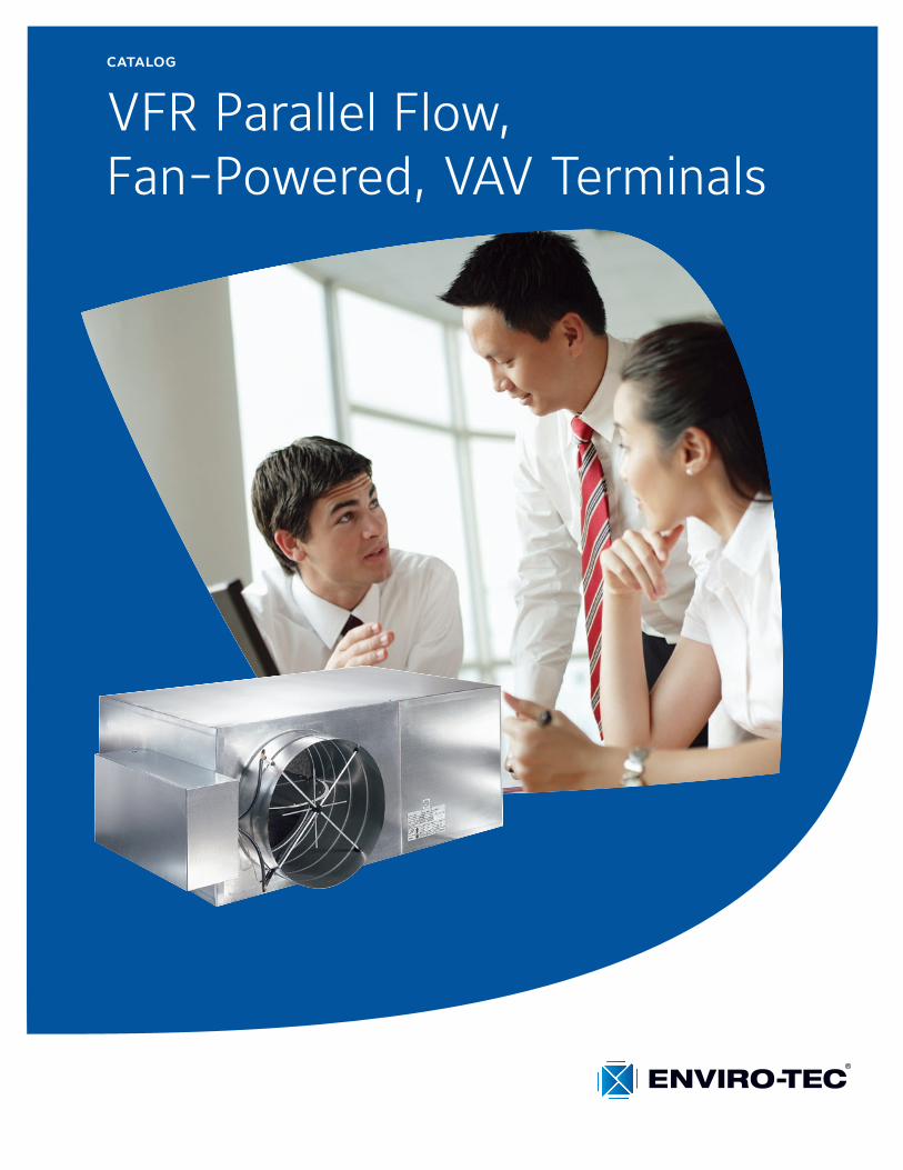
catalog
VFR Parallel Flow, Fan-Powered, VAV Terminals
2 ENVIRO-TEC
Parallel Fan-Powered, VAV Terminals Catalog: ET130.13-EG6 (418)
Features and Benefits . . . . . . . . . . . . . . . . . . . . . . . . . . . . 2Controls . . . . . . . . . . . . . . . . . . . . . . . . . . . . . . . . . . . . . . . 4Construction Features . . . . . . . . . . . . . . . . . . . . . . . . . . . . 5Standard and Optional Features . . . . . . . . . . . . . . . . . . . . 7Application and Selection . . . . . . . . . . . . . . . . . . . . . . . . . . 8Dimensional Data . . . . . . . . . . . . . . . . . . . . . . . . . . . . . . . 11Primary Airflow Calibration . . . . . . . . . . . . . . . . . . . . . . . . 13General Selection Data, PSC Motor . . . . . . . . . . . . . . . . 14Sound Power Data, PSC Motor . . . . . . . . . . . . . . . . . . . . 16Fan Performance Data, PSC Motor . . . . . . . . . . . . . . . . . 20EC Fan Motor Option . . . . . . . . . . . . . . . . . . . . . . . . . . . . 23General Selection Data, EC Motor . . . . . . . . . . . . . . . . . . 24Fan Performance Data, EC Motor . . . . . . . . . . . . . . . . . . 25AHRI Ratings . . . . . . . . . . . . . . . . . . . . . . . . . . . . . . . . . . 26Electric Heat . . . . . . . . . . . . . . . . . . . . . . . . . . . . . . . . . . . 27Hot Water Coil Data . . . . . . . . . . . . . . . . . . . . . . . . . . . . . 28Guide Specifications . . . . . . . . . . . . . . . . . . . . . . . . . . . . . 32
TABLE OF CONTENTS
QUIET COMFORT
Model VFR fan terminals are specifically designed for quiet operation . They also offer improved space comfort and flexibility for a wide variety of HVAC systems . This is critical in today’s buildings, where occupants are placing more emphasis on indoor acoustics .
OCCUPANT-SENSITIVE DESIGN
Due to heightened interest in Indoor Air Quality, many HVAC system designers are focusing on the effects of particulate contamination within a building’s occupied space . Often, HVAC system noise is overlooked as a source of occupied space contamination . The VFR terminal is specifically designed to eliminate obtrusive fan noise from reaching the occupants .
Occupants will benefit from the VFR design that mini-mizes low frequency (125Hz-250Hz) sound levels that typically dominate the space sound level .
DESIGN FLEXIBILITY
Selection and Layout. The VFR provides flexibility in system design . Reduced noise at the fan terminal allows the system designer to place properly sized units directly above occupied spaces . It is not necessary to use the crowded space above a hall or corridor to locate the equipment . This will reduce lengthy and expensive discharge duct runs . The standard shallow casing height (14" up to 1000 CFM) minimizes conflict with other systems competing for ceiling space . The
FlowStar™ sensor ensures accurate control, even when space constraints do not permit long straight inlet duct runs to the terminal .
Sizes. Primary air valves and fans are available in various size combinations to provide fan capacities between 20% and 100% of the selected maximum primary airflow . Model VFR terminals are available with primary valves handling up to 4100 CFM . Six fan sizes provide a range of heating capacities between 50 and 2400 CFM .
A web-based Computer Selection Program, “Web-Select”, is available to facilitate the selection process . Contact your representative to obtain access to this powerful and time-saving program .
CONVENIENCE INSTALLATION
Quality. All VFR terminals are thoroughly inspected during each step of the manufacturing process, includ-ing a comprehensive “pre-ship” inspection, to assure the highest quality product available . Each unit is also “run tested” before leaving the factory to ensure trouble free field “start-up .”
Quick Installation. A standard single point electrical main power connection is provided . Electronic controls and electrical components are located on the same side of the casing for quick access, adjustment, and trouble-shooting . Installation time is minimized with the availability of factory calibrated controls .
FEATURES AND BENEFITS
NOTES:• Alldatahereinissubjecttochangewithoutnotice.• Construction drawings and performance data
contained herein should not be used for submittal purposes .
• ETLReportNumber476203.
ENVIRO-TEC 3
Parallel Fan-Powered, VAV Terminals Catalog: ET130.13-EG6 (418)
Finite fan speed adjustment is accomplished with an electronic SCR controller . The SCR fan speed control-ler is offered by ENVIRO-TEC and is compatible with the fan motor . This minimizes electronic interference and harmonic distortion that occurs from non-compat-ible motor and SCR components . Increased motor life and efficiency result from the compatible design .
VFR terminals utilize three tap motors that accommo-date a broad range of flow and static pressure field conditions while dramatically increasing efficiency .
The FlowStar™ sensor ensures accurate airflow mea-surement, regardless of the field installation conditions . A calibration label and wiring diagram is located on the terminal for quick reference during start-up .
The terminal is constructed to allow installation with standard metal hanging straps . Optional hanger brack-ets for use with all-thread support rods or wire hangers are also available .
VALUE AND SECURITY
Quality. All metal components are fabricated from galvanized steel . Unlike most manufacturers’ terminals, the steel used in the VFR is capable of withstanding a 125 hour salt spray test without showing any evidence of red rust .
Energy Efficiency. In addition to quiet and accurate temperature control, the building owner will benefit from lower operating costs . The highly amplified velocity pressure signal from the FlowStar™ inlet sensor allows precise airflow control at low air velocities .
The FlowStar™ sensor’s airfoil shape provides minimal
pressure drop across the terminal . This allows the central fan to run at a lower pressure and with less brake horsepower . Energy efficient three tap, three winding, permanent split capacitor fan motors are manufactured to ensure efficient, quiet, reliable, and low maintenance operation .
Three tap motors provide superior energy efficiency over single speed motors by delivering three separate horsepower outputs . For example, a nominal 1/2 HP motor delivers 1/3 HP on medium tap and 1/4 HP on low tap . This allows the motor to operate at a higher efficiency when at a reduced fan capacity .
Fan terminals that utilize a single speed motor must rely solely on an SCR controller to obtain the reduction in fan capacity . At minimum turndown, they suffer from excessive power consumption and high motor winding temperatures, significantly reducing the motor life .
Agency Certification. Model VFR terminals, including thosewithelectricheat,arelistedwithETLasanassem-bly,andbeartheETLlabel.VFRterminalscomplywithapplicable NEC requirements, are tested in accordance with AHRI Standard 880, and are certified by AHRI .
Maintenance and Service. VFR fan terminals require no periodic maintenance other than optional filter replacement . If component replacement becomes nec-essary, the unit is designed to minimize field labor . The bottom casing panel can be removed to provide easy access to the fan assembly, and the motor electrical leads are easily unplugged . Fan access is also pro-vided through the induction air inlet, except for hot water coil units .
FEATURES AND BENEFITS
4 ENVIRO-TEC
Parallel Fan-Powered, VAV Terminals Catalog: ET130.13-EG6 (418)
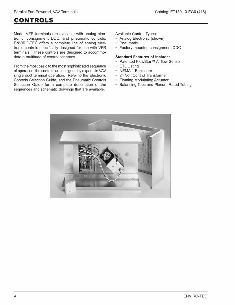
Model VFR terminals are available with analog elec-tronic, consignment DDC, and pneumatic controls . ENVIRO-TEC offers a complete line of analog elec-tronic controls specifically designed for use with VFR terminals . These controls are designed to accommo-date a multitude of control schemes .
From the most basic to the most sophisticated sequence of operation, the controls are designed by experts in VAV single duct terminal operation . Refer to the Electronic Controls Selection Guide, and the Pneumatic Controls Selection Guide for a complete description of the sequences and schematic drawings that are available .
Available Control Types:• AnalogElectronic(shown)• Pneumatic• FactorymountedconsignmentDDC
Standard Features of Include:• PatentedFlowStar™AirflowSensor• ETLListing• NEMA1Enclosure• 24VoltControlTransformer• FloatingModulatingActuator• BalancingTeesandPlenumRatedTubing
CONTROLS
ENVIRO-TEC 5
Parallel Fan-Powered, VAV Terminals Catalog: ET130.13-EG6 (418)
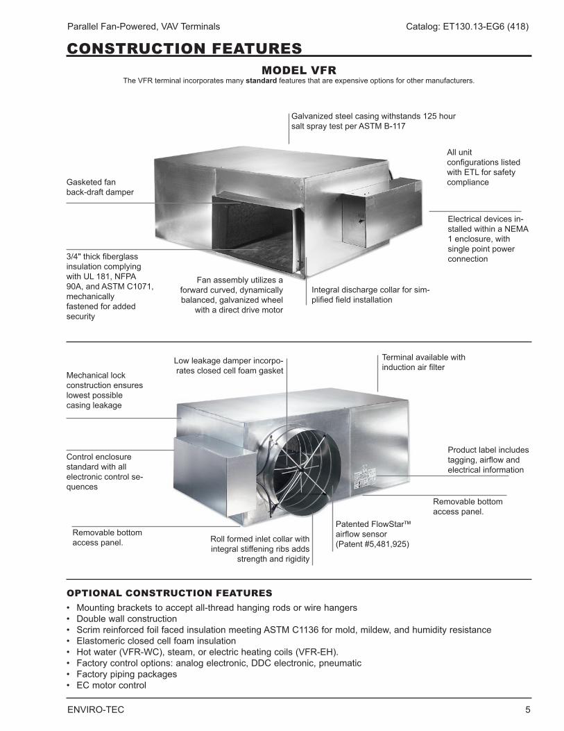
OPTIONAL CONSTRUCTION FEATURES• Mountingbracketstoacceptall-threadhangingrodsorwirehangers• Doublewallconstruction• ScrimreinforcedfoilfacedinsulationmeetingASTMC1136formold,mildew,andhumidityresistance• Elastomericclosedcellfoaminsulation• Hotwater(VFR-WC),steam,orelectricheatingcoils(VFR-EH).• Factorycontroloptions:analogelectronic,DDCelectronic,pneumatic• Factorypipingpackages• ECmotorcontrol
CONSTRUCTION FEATURESMODEL VFR
The VFR terminal incorporates many standard features that are expensive options for other manufacturers .
Gasketed fan back-draft damper
Mechanical lock construction ensures lowest possible casing leakage
Roll formed inlet collar with integral stiffening ribs adds
strength and rigidity
Patented FlowStar™ airflow sensor (Patent #5,481,925)
Terminal available with induction air filter
Electrical devices in-stalled within a NEMA 1 enclosure, with single point power connection
All unit configurations listed withETLforsafetycompliance
Product label includes tagging, airflow and electrical information
3/4" thick fiberglass insulation complying withUL181,NFPA90A, and ASTM C1071, mechanically fastened for added security
Lowleakagedamperincorpo-rates closed cell foam gasket
Control enclosure standard with all electronic control se-quences
Removable bottom access panel .
Removable bottom access panel .
Galvanized steel casing withstands 125 hour salt spray test per ASTM B-117
Fan assembly utilizes a forward curved, dynamically balanced, galvanized wheel
with a direct drive motor
Integral discharge collar for sim-plified field installation
6 ENVIRO-TEC
Parallel Fan-Powered, VAV Terminals Catalog: ET130.13-EG6 (418)
CONSTRUCTION FEATURES
Many VAV terminals waste energy due to an inferior airflow sensor design that requires the minimum CFM setpoint to be much higher than the IAQ calculation requirement . This is common with interior spaces that will be effected year round . These inferior VAV terminals waste energy in several ways . First, the primary air fan (e .g . AHU) supplies more CFM than the building requires . The higher minimum CFM setpoint overcools the zone with VAV terminals without integral heat . To maintain thermal comfort a building engineer would need to change the minimum setpoint to zero CFM compromis-ing indoor air quality . Inferior VAV terminals with integral heat provide adequate comfort in the space but waste significant energy as energy is consumed to mechani-cally cool the primary air only to have more energy consumed to heat the cooled primary air . Significant energy savings is obtained with proper sizing and by making sure approved VAV terminals are capable of controlling at low CFM setpoints, providing the minimum ventilation requirement .
Currently, most DDC controllers have a minimum dif-ferential pressure limitation between 0 .015" and 0 .05" w .g . The major DDC manufacturers can control down to 0 .015" w .g . An airflow sensor that does not amplify, e .g ., a Pitot tube, requires about 490 FPM to develop 0 .015" w .g . differential pressure . The FlowStar™ devel-ops 0 .015" w .g . pressure with only 290 FPM on a size 6 terminal and less than 325 FPM for a size 16 . Consequently, VAV terminals utilizing a non-amplifying type sensor could have minimum CFM's that are well over 50% higher than an ENVIRO-TEC terminal . Many airflow sensors provide some degree of amplification simply due to the decrease in free area of the inlet from large area of the sensor . These VAV terminals still require minimum CFM's up to 30% higher than an ENVIRO-TEC terminal, have higher sound levels, and higher pressure drop requiring additional energy con-sumption at the primary air fan .
A VAV system designed with ENVIRO-TEC terminals consumes significantly less energy than a comparable system with competitor's terminals . The FlowStar™
airflow sensor reduces energy consumption by allowing lower zone minimum CFM setpoints, greatly reducing or eliminating “reheat”, and by imposing less resistance on the primary air fan .
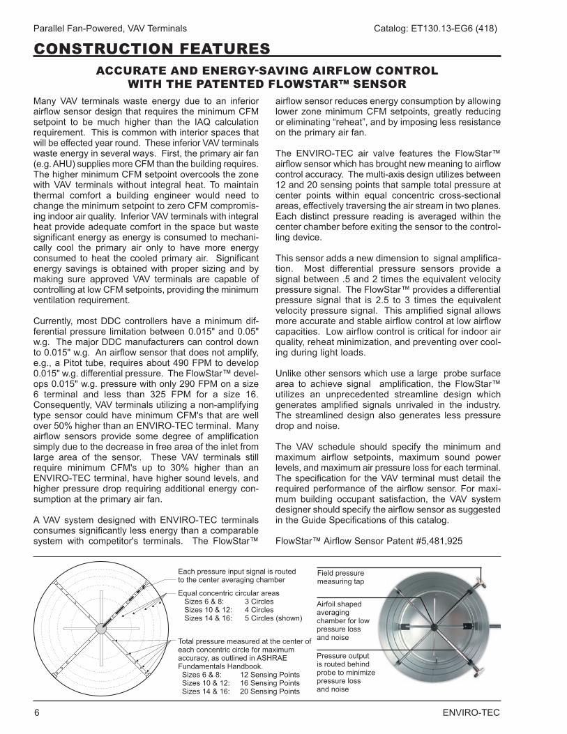
The ENVIRO-TEC air valve features the FlowStar™ airflow sensor which has brought new meaning to airflow control accuracy . The multi-axis design utilizes between 12 and 20 sensing points that sample total pressure at center points within equal concentric cross-sectional areas, effectively traversing the air stream in two planes . Each distinct pressure reading is averaged within the center chamber before exiting the sensor to the control-ling device .
This sensor adds a new dimension to signal amplifica-tion . Most differential pressure sensors provide a signal between .5 and 2 times the equivalent velocity pressure signal . The FlowStar™ provides a differential pressure signal that is 2 .5 to 3 times the equivalent velocity pressure signal . This amplified signal allows more accurate and stable airflow control at low airflow capacities.Lowairflowcontroliscriticalforindoorairquality, reheat minimization, and preventing over cool-ing during light loads .
Unlike other sensors which use a large probe surface area to achieve signal amplification, the FlowStar™ utilizes an unprecedented streamline design which generates amplified signals unrivaled in the industry . The streamlined design also generates less pressure drop and noise .
The VAV schedule should specify the minimum and maximum airflow setpoints, maximum sound power levels, and maximum air pressure loss for each terminal . The specification for the VAV terminal must detail the required performance of the airflow sensor . For maxi-mum building occupant satisfaction, the VAV system designer should specify the airflow sensor as suggested in the Guide Specifications of this catalog .
FlowStar™ Airflow Sensor Patent #5,481,925
ACCURATE AND ENERGY-SAVING AIRFLOW CONTROL WITH THE PATENTED FLOWSTAR™ SENSOR
Each pressure input signal is routed to the center averaging chamber
Equal concentric circular areas Sizes 6 & 8: 3 Circles Sizes 10 & 12: 4 Circles Sizes 14 & 16: 5 Circles (shown)
Total pressure measured at the center of each concentric circle for maximum accuracy, as outlined in ASHRAE Fundamentals Handbook . Sizes 6 & 8: 12 Sensing Points Sizes 10 & 12: 16 Sensing Points Sizes 14 & 16: 20 Sensing Points
Field pressure measuring tap
Airfoil shaped averaging chamber for low pressure loss and noise
Pressure output is routed behind probe to minimize pressure loss and noise
ENVIRO-TEC 7
Parallel Fan-Powered, VAV Terminals Catalog: ET130.13-EG6 (418)
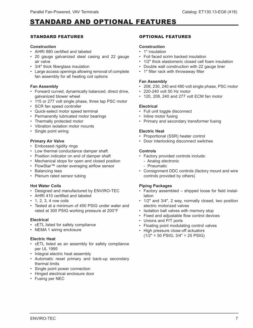
STANDARD AND OPTIONAL FEATURES
STANDARD FEATURES
Construction• AHRI880certifiedandlabeled• 20 gauge galvanized steel casing and 22 gauge
air valve• 3/4"thickfiberglassinsulation• Largeaccessopeningsallowingremovalofcomplete
fan assembly for all heating coil options
Fan Assembly• Forwardcurved,dynamicallybalanced,directdrive,
galvanized blower wheel• 115or277voltsinglephase,threetapPSCmotor• SCRfanspeedcontroller• Quick-selectmotorspeedterminal• Permanentlylubricatedmotorbearings• Thermallyprotectedmotor• Vibrationisolationmotormounts• Singlepointwiring
Primary Air Valve• Embossedrigidityrings• Lowthermalconductancedampershaft• Positionindicatoronendofdampershaft• Mechanicalstopsforopenandclosedposition• FlowStar™centeraveragingairflowsensor• Balancingtees• Plenumratedsensortubing
Hot Water Coils• DesignedandmanufacturedbyENVIRO-TEC• AHRI410certifiedandlabeled• 1,2,3,4rowcoils• Testedataminimumof450PSIGunderwaterand
rated at 300 PSIG working pressure at 200°F
Electrical• cETLlistedforsafetycompliance• NEMA1wiringenclosure
Electric Heat• cETL listedasanassembly for safety complianceperUL1995
• Integralelectricheatassembly• Automatic reset primary and back-up secondary
thermal limits• Singlepointpowerconnection• Hingedelectricalenclosuredoor• FusingperNEC
OPTIONAL FEATURES
Construction• 1"insulation• Foilfacedscrimbackedinsulation• 1/2"thickelastomericclosedcellfoaminsulation• Doublewallconstructionwith22gaugeliner• 1"filterrackwiththrowawayfilter
Fan Assembly• 208,230,240and480voltsinglephase,PSCmotor• 220-240volt50Hzmotor• 120,208,240and277voltECMfanmotor
Electrical• Fullunittoggledisconnect• Inlinemotorfusing• Primaryandsecondarytransformerfusing
Electric Heat• Proportional(SSR)heatercontrol• Doorinterlockingdisconnectswitches
Controls• Factoryprovidedcontrolsinclude: - Analog electronic - Pneumatic• ConsignmentDDCcontrols(factorymountandwire
controls provided by others)
Piping Packages• Factoryassembled–shippedlooseforfieldinstal-
lation• 1/2"and3/4",2way,normallyclosed,twoposition
electric motorized valves• Isolationballvalveswithmemorystop• Fixedandadjustableflowcontroldevices• UnionsandP/Tports• Floatingpointmodulatingcontrolvalves• Highpressureclose-offactuators (1/2" = 50 PSIG; 3/4" = 25 PSIG)
8 ENVIRO-TEC
Parallel Fan-Powered, VAV Terminals Catalog: ET130.13-EG6 (418)
APPLICATION AND SELECTION
PURPOSE OF PARALLEL FLOW FAN TERMINALS
Parallel flow fan powered terminals offer improved space comfort and flexibility in a wide variety of appli-cations . Substantial operating savings can be realized through the recovery of waste heat, and night setback operation .
Heat Recovery. The VFR recovers heat from lights and core areas to offset heating loads in perimeter zones . Additional heat is available at the terminal unit using electric, steam, or hot water heating coils . Controls are available to energize remote heating devices such as wall fin, fan coils, radiant panels, and roof load plenum unit heaters .
Typical Sequences of Operation. The VFR provides variable volume, constant temperature air in the cooling mode, and constant volume, variable temperature air in the heating mode .
At the design cooling condition, the primary air valve is handling the maximum scheduled airflow capacity while the unit fan is off . As the cooling load decreases, the primary air valve throttles toward the minimum sched-uled airflow capacity . A further decrease in the cooling load causes the unit fan to start, inducing warm air from the ceiling plenum which increases the discharge air temperature to the zone . When the heating load increases, the optional hot water coil or electric heater is energized to maintain comfort conditions .
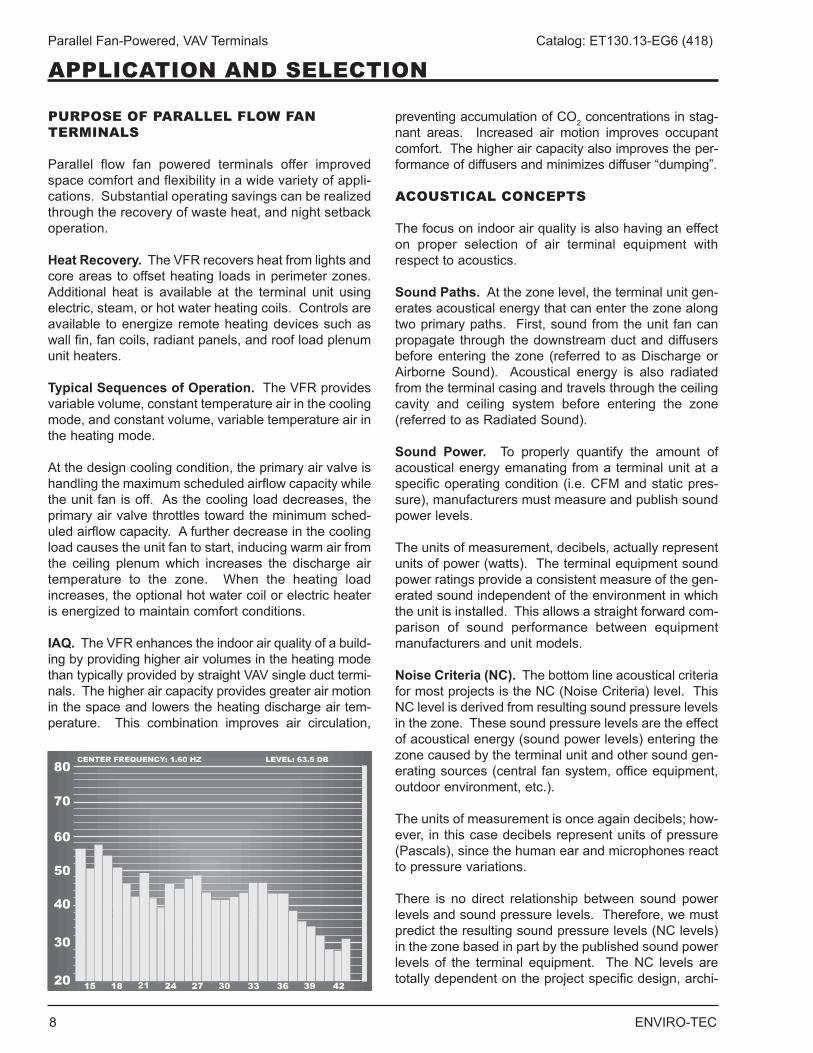
IAQ. The VFR enhances the indoor air quality of a build-ing by providing higher air volumes in the heating mode than typically provided by straight VAV single duct termi-nals . The higher air capacity provides greater air motion in the space and lowers the heating discharge air tem-perature . This combination improves air circulation,
preventing accumulation of CO2 concentrations in stag-nant areas . Increased air motion improves occupant comfort . The higher air capacity also improves the per-formance of diffusers and minimizes diffuser “dumping” .
ACOUSTICAL CONCEPTS
The focus on indoor air quality is also having an effect on proper selection of air terminal equipment with respect to acoustics .
Sound Paths. At the zone level, the terminal unit gen-erates acoustical energy that can enter the zone along two primary paths . First, sound from the unit fan can propagate through the downstream duct and diffusers before entering the zone (referred to as Discharge or Airborne Sound) . Acoustical energy is also radiated from the terminal casing and travels through the ceiling cavity and ceiling system before entering the zone (referred to as Radiated Sound) .
Sound Power. To properly quantify the amount of acoustical energy emanating from a terminal unit at a specific operating condition (i .e . CFM and static pres-sure), manufacturers must measure and publish sound power levels .
The units of measurement, decibels, actually represent units of power (watts) . The terminal equipment sound power ratings provide a consistent measure of the gen-erated sound independent of the environment in which the unit is installed . This allows a straight forward com-parison of sound performance between equipment manufacturers and unit models .
Noise Criteria (NC). The bottom line acoustical criteria for most projects is the NC (Noise Criteria) level . This NC level is derived from resulting sound pressure levels in the zone . These sound pressure levels are the effect of acoustical energy (sound power levels) entering the zone caused by the terminal unit and other sound gen-erating sources (central fan system, office equipment, outdoor environment, etc .) .
The units of measurement is once again decibels; how-ever, in this case decibels represent units of pressure (Pascals), since the human ear and microphones react to pressure variations .
There is no direct relationship between sound power levels and sound pressure levels . Therefore, we must predict the resulting sound pressure levels (NC levels) in the zone based in part by the published sound power levels of the terminal equipment . The NC levels are totally dependent on the project specific design, archi-
ENVIRO-TEC 9
Parallel Fan-Powered, VAV Terminals Catalog: ET130.13-EG6 (418)
tecturally and mechanically . For a constant operating condition (fixed sound power levels), the resulting NC level in the zone will vary from one project to another .
AHRI 885. A useful tool to aid in predicting space sound pressure levels is an application standard referred to as AHRI Standard 885 . This standard provides information (tables, formulas, etc .) required to calculate the attenu-ation of the ductwork, ceiling cavity, ceiling system, and conditioned space below a terminal unit . These attenu-ation values are referred to as the “transfer function” since they are used to transfer from the manufacturer’s sound power levels to the estimated sound pressure levels resulting in the space below, and/or served by the terminal unit . The standard does not provide all of the necessary information to accommodate every conceiv-able design; however, it does provide enough information to approximate the transfer function for most applications . Furthermore, an Appendix is provided that contains typical attenuation values . Some manufactur-ers utilize different assumptions with respect to a "typical" project design; therefore, cataloged NC levels should not be used to compare acoustical performance . Only certified sound power levels should be used for this purpose .
GENERAL DESIGN RECOMMENDATIONS FOR A QUIET SYSTEM
The AHU. Sound levels in the zone are frequently impacted by central fan discharge noise that either breaks out (radiates) from the ductwork or travels through the distribution ductwork and enters the zone as airborne (discharge) sound . Achieving acceptable sound levels in the zone begins with a properly designed central fan system which delivers relatively quiet air to each zone .
Supply Duct Pressure. One primary factor contributing to noisy systems is high static pressure in the primary air duct . This condition causes higher sound levels from the central fan and also higher sound levels from the terminal unit, as the primary air valve closes to reduce the pressure . This condition is compounded when flex-ible duct is utilized at the terminal inlet, which allows the central fan noise and air valve noise to break out into the ceiling cavity and then enter the zone located below the terminal . Ideally, the system static pressure should be reduced to the point where the terminal unit installed on the duct run associated with the highest pressure drop has the minimum required inlet pressure to deliver the design airflow to the zone . For systems that will have substantially higher pressure variances from one zone to another, special attention should be paid to the proper selection of air terminal equipment .
To date, the most common approach has been to select (size) all of the terminals based on the worst case (high-est inlet static pressure) condition . Typically, this results in 80% (or higher) of the terminal units being oversized for their application . This in turn results in much higher equipment costs, but more importantly, drastically reduced operating efficiency of each unit . This conse-quently decreases the ability to provide comfort control in the zone . In addition, the oversized terminals cannot adequately control the minimum ventilation capacity required in the heating mode .
A more prudent approach is to utilize a pressure reduc-ing device upstream of the terminal unit on those few zones closest to the central fan . This device could simply be a manual quadrant type damper if located well upstream of the terminal inlet . In tight quarters, perfo-rated metal can be utilized as a quiet means of reducing system pressure . This approach allows all of the termi-nal units to experience a similar (lower) inlet pressure . They can be selected in a consistent manner at lower inlet pressure conditions that will allow more optimally sized units .
Inlet Duct Configuration. Inlet duct that is the same size as the inlet collar and as straight as possible will achieve the best acoustical performance . For critical applications, flexible duct should not be utilized at the terminal inlet .
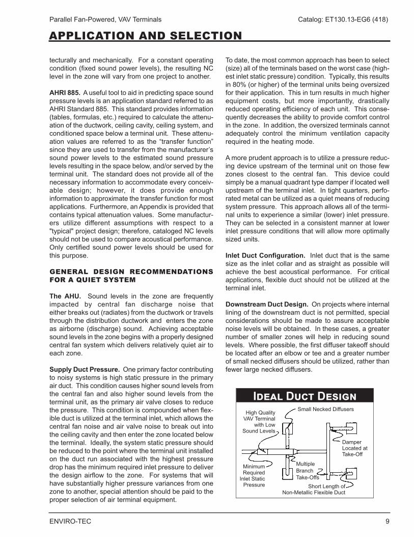
Downstream Duct Design. On projects where internal lining of the downstream duct is not permitted, special considerations should be made to assure acceptable noise levels will be obtained . In these cases, a greater number of smaller zones will help in reducing sound levels . Where possible, the first diffuser takeoff should be located after an elbow or tee and a greater number of small necked diffusers should be utilized, rather than fewer large necked diffusers .
Ideal Duct DesignSmall Necked Diffusers
Damper LocatedatTake-Off
High Quality VAV Terminal
withLowSoundLevels
Minimum Required
Inlet Static Pressure ShortLengthof
Non-Metallic Flexible Duct
Multiple Branch Take-Offs
APPLICATION AND SELECTION
10 ENVIRO-TEC
Parallel Fan-Powered, VAV Terminals Catalog: ET130.13-EG6 (418)
APPLICATION AND SELECTION
The downstream ductwork should be carefully designed and installed to avoid noise regeneration . Bull head tee arrangements should be located sufficiently down-stream of the terminal discharge to provide an established flow pattern downstream of the fan . Place diffusers downstream of the terminal after the airflow has completely developed .
Downstream splitter dampers can cause noise problems if placed too close to the terminal, or when excessive air velocities exist . If tee arrangements are employed, volume dampers should be used in each branch of the tee, and balancing dampers should be provided at each diffuser tap . This arrangement provides maximum flex-ibility in quiet balancing of the system . Casing radiated sound usually dictates the overall room sound levels directly below the terminal . Because of this, special consideration should be given to the location of these terminals aswell as to the size of the zone. Largerzones should have the terminal located over a corridor or open plan office space and not over a small confined private office . Fan powered terminals should never be installed over small occupied spaces where the wall partitions extend from slab-to-slab (i .e . fire walls or privacy walls) .
Fan Terminal Isolation. Model VFR fan terminals are equipped with sufficient internal vibration dampening means to prevent the need for additional external isola-tion . Flexible duct connectors at the unit discharge typically do more harm than good . The sagging mem-brane causes higher air velocities and turbulence, which translates into noise . Furthermore, the discharge noise breaks out of this fitting more than with a hard sheet metal fitting .
SELECTION GUIDELINES
The VFR product line has been designed to provide maximum flexibility in matching primary air valve capac-ities (cooling loads) with unit fan capacities (heating loads) . The overall unit size is dictated by the primary air valve sizes (cooling design capacity) . With each unit size, various fan sizes are available to handle a wide range of fan capacities from relatively low heating airflow capacities (i .e . 25% of maximum primary capacity) all the way up to relatively high heating airflow capacities (i .e . 100% of maximum primary) .
The primary air valve should be sized first to determine the unit size . Typically, the primary air valve sound is insignificant relative to the unit fan sound performance . The selection process typically involves choosing an air valve size that is as small as possible while yielding acceptable sound levels and pressure drop . For non-acoustically sensitive applications such as shopping
malls and airports, the primary air valve can be sized at the maximum rated capacity .
After the primary air valve has been selected, the fan can be selected from the various sizes available for that unit size . The selection is made by cross plotting the specified fan capacity and external static pressure on the appropriate fan performance curves . Terminals utiliz-ing hot water heating coils require the summation of the coil air pressure drop and the design E .S .P . to determine the total E .S .P . It is common to have more than one fan size which can meet the design requirements . Typically, the selection begins with the smallest fan that can meet the capacity . Occasionally, this selection may not meet the acoustical requirements and thus, the next larger fan size would be selected .
Fan selections can be made anywhere in the non-shaded areas . Each fan performance curve depicts the actual performance of the relative motor tap without any additional fan balance adjustment . Actual specified capacities which fall below a particular fan curve (low, medium, or high) is obtained by adjustment of the elec-tronic (SCR) fan speed controller .
SYSTEM PRESSURE CONSIDERATIONS
The central fan is required to produce sufficient inlet static pressure to force the air through the primary air valve, unit casing, downstream ductwork and fittings, and diffusers with the unit fan off . The VFR has been designed to reduce central fan power consumption by placing the optional hot water heating coil in the induc-tion air stream, eliminating the coil from these central system pressure considerations .
The industry standard for testing and rating air terminal units (AHRI 880) requires that published pressure drop performance be measured with hard, straight, unlined duct entering and leaving the terminal unit . On many projects, due to the limited available space, terminal units are not installed in this optimum manner . Frequently, flexible duct is used at the terminal inlet and a metal transition is utilized at the discharge . The entrance and exit losses in these instances exceed the actual terminal unit pressure loss . It is important to consider terminal unit pressure loss as well as those losses associated with the entire distribution ductwork (as outlined in applicable ASHRAE Handbooks) when sizing central system fan requirements .
A web-based Computer Selection Program, “Web-Select”, is available to facilitate the selection process . Contact your representative to obtain access to this powerful and time-saving program .
ENVIRO-TEC 11
Parallel Fan-Powered, VAV Terminals Catalog: ET130.13-EG6 (418)
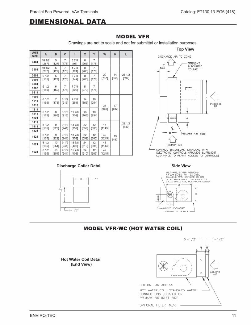
DIMENSIONAL DATA
MODEL VFR
MODEL VFR-WC (HOT WATER COIL)
Top View
Discharge Collar Detail Side View
Drawings are not to scale and not for submittal or installation purposes .
UNIT SIZE A B C I X Y W H L
0404 10 1/2 [267]
5 [127]
7 [178]
3 7/8 [98]
8 [203]
7 [178]
29 [737]
14 [356]
23 1/2 [597]
0504 10 1/2 [267]
5 [127]
7 [178]
4 7/8 [124]
8 [203]
7 [178]
0604 6 1/2 [165]
5 [127]
7 [178]
5 7/8 [149]
8 [203]
7 [178]0606
08046 1/2 [165]
6 [152]
7 [178]
7 7/8 [200]
11 [279]
7 [178]0806
08111006
6 1/2 [165]
7 [178]
8 1/2 [216]
9 7/8 [251]
14 [356]
10 [254]
37 [940]
17 [432]
29 1/2 [749]
101110181211
6 1/2 [165]
8 [203]
8 1/2 [216]
11 7/8 [302]
16 [406]
10 [254]1218
12211411
6 1/2 [165]
9 [229]
9 1/2 [241]
13 7/8 [352]
22 [559]
12 [305]
45 [1143]
19 [483]
14181421
1424 6 1/2 [165]
9 [229]
9 1/2 [241]
13 7/8 [352]
22 [559]
12 [305]
49 [1245]
1621 6 1/2 [165]
10 [254]
9 1/2 [241]
15 7/8 [403]
24 [610]
12 [305]
45 [1143]
1624 6 1/2 [165]
10 [254]
9 1/2 [241]
15 7/8 [403]
24 [610]
12 [305]
49 [1245]
Hot Water Coil Detail (End View)
12 ENVIRO-TEC
Parallel Fan-Powered, VAV Terminals Catalog: ET130.13-EG6 (418)
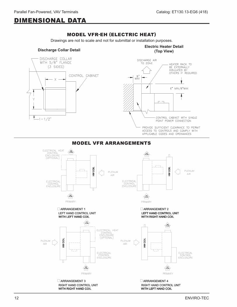
DIMENSIONAL DATA
MODEL VFR-EH (ELECTRIC HEAT)
MODEL VFR ARRANGEMENTS
Drawings are not to scale and not for submittal or installation purposes .Electric Heater Detail
(Top View)Discharge Collar Detail
ARRANGEMENT 2LEFT HAND CONTROL UNILEFT HAND CONTROL UNITWITH RIGHT HAND COIWITH RIGHT HAND COIL
ARRANGEMENT 1
WITH LEFT HAND COIWITH LEFT HAND COILLEFT HAND CONTROL UNIT
HW
CO
IH
W C
OIL
HW
CO
IH
W C
OIL
AIRFLOW
AIRFLOW
AIRFLOW
AIRFLOW
ARRANGEMENT 3RIGHT HAND CONTROL UNIT WITH RIGHT HAND COIWITH RIGHT HAND COIL
ARRANGEMENT 4RIGHT HAND CONTROL UNIT WITH LEFT HAND COIWITH LEFT HAND COIL
HW
CO
IH
W C
OIL
HW
CO
IH
W C
OIL
AIRFLOW
AIRFLOW
AIRFLOW
AIRFLOW
ENVIRO-TEC 13
Parallel Fan-Powered, VAV Terminals Catalog: ET130.13-EG6 (418)
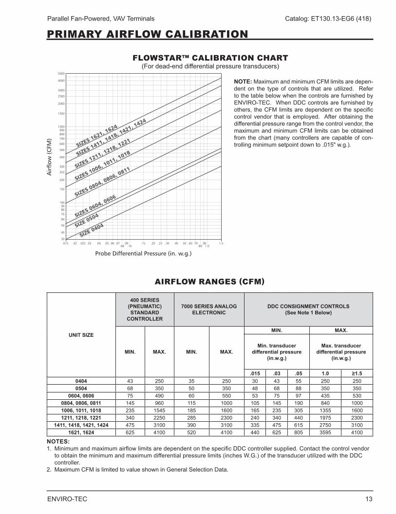
PRIMARY AIRFLOW CALIBRATION
NOTES:1 . Minimum and maximum airflow limits are dependent on the specific DDC controller supplied . Contact the control vendor
to obtain the minimum and maximum differential pressure limits (inches W .G .) of the transducer utilized with the DDC controller .
2 . Maximum CFM is limited to value shown in General Selection Data .
AIRFLOW RANGES (CFM)
FLOWSTAR™ CALIBRATION CHART(Fordead-enddifferentialpressuretransducers)
NOTE: Maximum and minimum CFM limits are depen-dent on the type of controls that are utilized . Refer to the table below when the controls are furnished by ENVIRO-TEC . When DDC controls are furnished by others, the CFM limits are dependent on the specific control vendor that is employed . After obtaining the differential pressure range from the control vendor, the maximum and minimum CFM limits can be obtained from the chart (many controllers are capable of con-trolling minimum setpoint down to .015" w .g .) .
UNIT SIZE
400 SERIES (PNEUMATIC) STANDARD
CONTROLLER
7000 SERIES ANALOG ELECTRONIC
DDC CONSIGNMENT CONTROLS (See Note 1 Below)
MIN. MAX. MIN. MAX.
MIN. MAX.
Min. transducer differential pressure
(in.w.g.)
Max. transducer differential pressure
(in.w.g.)
.015 .03 .05 1.0 ≥1.50404 43 250 35 250 30 43 55 250 2500504 68 350 50 350 48 68 88 350 350
0604, 0606 75 490 60 550 53 75 97 435 5300804, 0806, 0811 145 960 115 1000 105 145 190 840 10001006, 1011, 1018 235 1545 185 1600 165 235 305 1355 16001211, 1218, 1221 340 2250 285 2300 240 340 440 1975 2300
1411, 1418, 1421, 1424 475 3100 390 3100 335 475 615 2750 31001621, 1624 625 4100 520 4100 440 625 805 3595 4100
14 ENVIRO-TEC
Parallel Fan-Powered, VAV Terminals Catalog: ET130.13-EG6 (418)
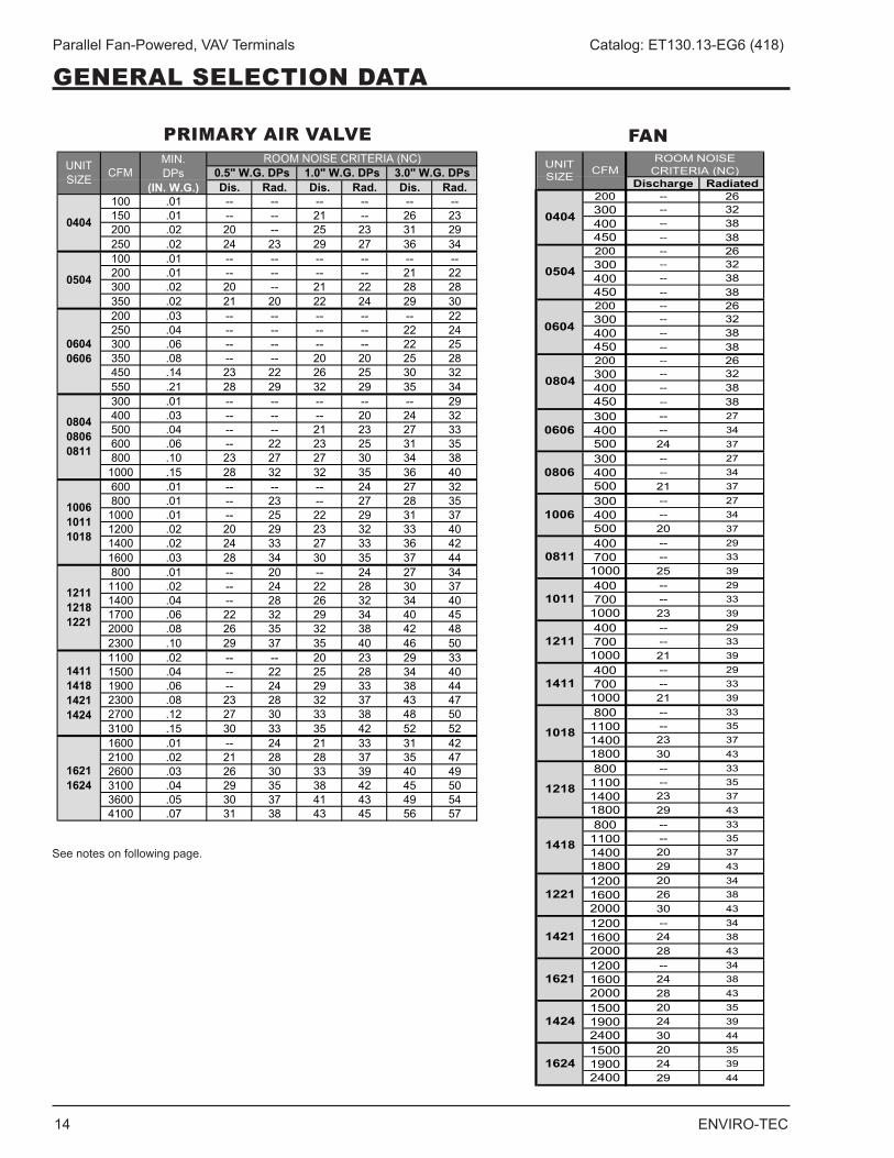
GENERAL SELECTION DATA
FANPRIMARY AIR VALVE
Discharge Radiated200 -- 26300 -- 32400 -- 38450 -- 38200 -- 26300 -- 32400 -- 38450 -- 38200 -- 26300 -- 32400 -- 38450 -- 38200 -- 26300 -- 32400 -- 38450 -- 38300 -- 27400 -- 34500 24 37300 -- 27400 -- 34500 21 37300 -- 27400 -- 34500 20 37400 -- 29700 -- 33
1000 25 39400 -- 29700 -- 33
1000 23 39400 -- 29700 -- 33
1000 21 39400 -- 29700 -- 33
1000 21 39800 -- 33
1100 -- 351400 23 371800 30 43800 -- 33
1100 -- 351400 23 371800 29 43800 -- 33
1100 -- 351400 20 371800 29 431200 20 341600 26 382000 30 431200 -- 341600 24 382000 28 431200 -- 341600 24 382000 28 431500 20 351900 24 392400 30 441500 20 351900 24 392400 29 44
ROOM NOISE CRITERIA (NC)UNIT
SIZE CFM
0404
0504
0604
0804
0606
0806
1006
0811
1011
1211
1621
1424
1624
1411
1018
1218
1418
1221
1421
Dis. Rad. Dis. Rad. Dis. Rad.100 .01 -- -- -- -- -- --150 .01 -- -- 21 -- 26 23200 .02 20 -- 25 23 31 29250 .02 24 23 29 27 36 34100 .01 -- -- -- -- -- --200 .01 -- -- -- -- 21 22300 .02 20 -- 21 22 28 28350 .02 21 20 22 24 29 30200 .03 -- -- -- -- -- 22250 .04 -- -- -- -- 22 24300 .06 -- -- -- -- 22 25350 .08 -- -- 20 20 25 28450 .14 23 22 26 25 30 32550 .21 28 29 32 29 35 34300 .01 -- -- -- -- -- 29400 .03 -- -- -- 20 24 32500 .04 -- -- 21 23 27 33600 .06 -- 22 23 25 31 35800 .10 23 27 27 30 34 381000 .15 28 32 32 35 36 40600 .01 -- -- -- 24 27 32800 .01 -- 23 -- 27 28 351000 .01 -- 25 22 29 31 371200 .02 20 29 23 32 33 401400 .02 24 33 27 33 36 421600 .03 28 34 30 35 37 44800 .01 -- 20 -- 24 27 341100 .02 -- 24 22 28 30 371400 .04 -- 28 26 32 34 401700 .06 22 32 29 34 40 452000 .08 26 35 32 38 42 482300 .10 29 37 35 40 46 501100 .02 -- -- 20 23 29 331500 .04 -- 22 25 28 34 401900 .06 -- 24 29 33 38 442300 .08 23 28 32 37 43 472700 .12 27 30 33 38 48 503100 .15 30 33 35 42 52 521600 .01 -- 24 21 33 31 422100 .02 21 28 28 37 35 472600 .03 26 30 33 39 40 493100 .04 29 35 38 42 45 503600 .05 30 37 41 43 49 544100 .07 31 38 43 45 56 57
0504
0404
16211624
1411141814211424
121112181221
100610111018
080408060811
06040606
UNIT SIZE CFM
MIN . DPs
(IN. W.G.)
ROOM NOISE CRITERIA (NC)0.5" W.G. DPs 1.0" W.G. DPs 3.0" W.G. DPs
See notes on following page .
ENVIRO-TEC 15
Parallel Fan-Powered, VAV Terminals Catalog: ET130.13-EG6 (418)
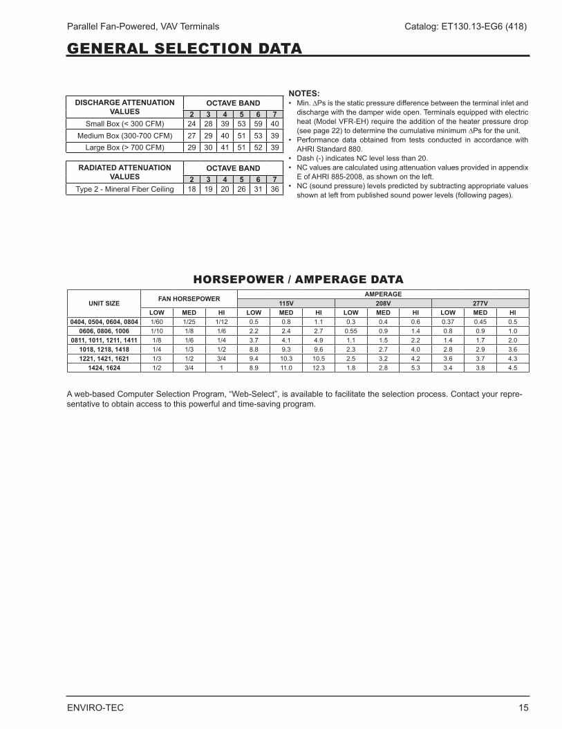
NOTES:• Min.∆Psisthestaticpressuredifferencebetweentheterminalinletand
discharge with the damper wide open . Terminals equipped with electric heat (Model VFR-EH) require the addition of the heater pressure drop (seepage22)todeterminethecumulativeminimum∆Psfortheunit.
• Performance data obtained from tests conducted in accordancewithAHRI Standard 880 .
• Dash(-)indicatesNClevellessthan20.• NCvaluesarecalculatedusingattenuationvaluesprovidedinappendix
E of AHRI 885-2008, as shown on the left .• NC(soundpressure)levelspredictedbysubtractingappropriatevalues
shown at left from published sound power levels (following pages) .
HORSEPOWER / AMPERAGE DATA
DISCHARGE ATTENUATION VALUES
OCTAVE BAND2 3 4 5 6 7
Small Box (< 300 CFM) 24 28 39 53 59 40Medium Box (300-700 CFM) 27 29 40 51 53 39LargeBox(>700CFM) 29 30 41 51 52 39
RADIATED ATTENUATION VALUES
OCTAVE BAND2 3 4 5 6 7
Type 2 - Mineral Fiber Ceiling 18 19 20 26 31 36
UNIT SIZE FAN HORSEPOWER AMPERAGE115V 208V 277V
LOW MED HI LOW MED HI LOW MED HI LOW MED HI0404, 0504, 0604, 0804 1/60 1/25 1/12 0 .5 0 .8 1 .1 0 .3 0 .4 0 .6 0 .37 0 .45 0 .5
0606, 0806, 1006 1/10 1/8 1/6 2 .2 2 .4 2 .7 0 .55 0 .9 1 .4 0 .8 0 .9 1 .00811, 1011, 1211, 1411 1/8 1/6 1/4 3 .7 4 .1 4 .9 1 .1 1 .5 2 .2 1 .4 1 .7 2 .0
1018, 1218, 1418 1/4 1/3 1/2 8 .8 9 .3 9 .6 2 .3 2 .7 4 .0 2 .8 2 .9 3 .61221, 1421, 1621 1/3 1/2 3/4 9 .4 10 .3 10 .5 2 .5 3 .2 4 .2 3 .6 3 .7 4 .3
1424, 1624 1/2 3/4 1 8 .9 11 .0 12 .3 1 .8 2 .8 5 .3 3 .4 3 .8 4 .5
A web-based Computer Selection Program, “Web-Select”, is available to facilitate the selection process . Contact your repre-sentative to obtain access to this powerful and time-saving program .
GENERAL SELECTION DATA
16 ENVIRO-TEC
Parallel Fan-Powered, VAV Terminals Catalog: ET130.13-EG6 (418)
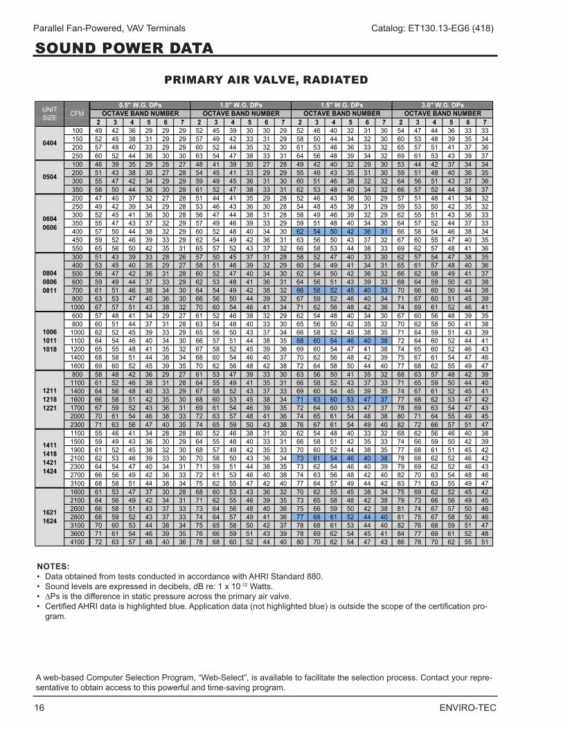
NOTES:• DataobtainedfromtestsconductedinaccordancewithAHRIStandard880.• Soundlevelsareexpressedindecibels,dBre:1x10-12 Watts .• ∆Ps is the difference in static pressure across the primary air valve .• CertifiedAHRIdataishighlightedblue.Applicationdata(nothighlightedblue)isoutsidethescopeofthecertificationpro- gram .
PRIMARY AIR VALVE, RADIATED
2 3 4 5 6 7 2 3 4 5 6 7 2 3 4 5 6 7 2 3 4 5 6 7100 49 42 36 29 29 29 52 45 39 30 30 29 52 46 40 32 31 30 54 47 44 36 33 33150 52 45 38 31 29 29 57 49 42 33 31 29 58 50 44 34 32 30 60 53 48 39 35 34200 57 48 40 33 29 29 60 52 44 35 32 30 61 53 46 36 33 32 65 57 51 41 37 36250 60 52 44 36 30 30 63 54 47 38 33 31 64 56 48 39 34 32 69 61 53 43 39 37100 46 39 35 29 26 27 48 41 39 30 27 28 49 42 40 32 29 30 53 44 42 37 34 34200 51 43 38 30 27 28 54 45 41 33 29 29 55 46 43 35 31 30 59 51 48 40 36 35300 55 47 42 34 29 29 59 49 45 36 31 30 60 51 46 38 32 32 64 56 51 43 37 36350 58 50 44 36 30 29 61 52 47 38 33 31 62 53 48 40 34 32 66 57 52 44 38 37200 47 40 37 32 27 28 51 44 41 35 29 28 52 46 43 36 30 29 57 51 48 41 34 32250 49 42 39 34 29 28 53 46 43 36 30 28 54 48 45 38 31 29 59 53 50 42 35 32300 52 45 41 36 30 28 56 47 44 38 31 28 58 49 46 39 32 29 62 55 51 43 36 33350 55 47 43 37 32 29 57 49 46 39 33 29 59 51 48 40 34 30 64 57 52 44 37 33400 57 50 44 38 32 29 60 52 48 40 34 30 62 54 50 42 36 31 66 58 54 46 38 34450 59 52 46 39 33 29 62 54 49 42 36 31 63 56 50 43 37 32 67 60 55 47 40 35550 65 56 50 42 35 31 65 57 52 43 37 32 66 58 53 44 38 33 69 62 57 48 41 36300 51 43 39 33 28 26 57 50 45 37 31 28 58 52 47 40 33 30 62 57 54 47 38 35400 53 45 40 35 29 27 58 51 46 39 32 29 60 54 49 41 34 31 65 61 57 48 40 36500 56 47 42 36 31 28 60 52 47 40 34 30 62 54 50 42 36 32 66 62 58 49 41 37600 59 49 44 37 33 29 62 53 48 41 36 31 64 56 51 43 39 33 68 64 59 50 43 38700 61 51 46 38 34 30 64 54 49 42 38 32 66 58 52 45 40 33 70 66 60 50 44 38800 63 53 47 40 36 30 66 56 50 44 39 32 67 59 52 46 40 34 71 67 60 51 45 391000 67 57 51 43 38 32 70 60 54 46 41 34 71 62 56 48 42 36 74 69 61 52 46 41600 57 48 41 34 29 27 61 52 46 38 32 29 62 54 48 40 34 30 67 60 56 48 39 35800 60 51 44 37 31 28 63 54 48 40 33 30 65 56 50 42 35 32 70 62 58 50 41 381000 62 52 45 39 33 29 65 56 50 43 37 34 66 58 52 45 38 35 71 64 59 51 43 391100 64 54 46 40 34 30 66 57 51 44 38 35 68 60 54 46 40 38 72 64 60 52 44 411200 65 55 48 41 35 32 67 58 52 45 39 36 69 60 54 47 41 38 74 65 60 52 46 431400 68 58 51 44 38 34 68 60 54 46 40 37 70 62 56 48 42 39 75 67 61 54 47 461600 69 60 52 45 39 35 70 62 56 48 42 38 72 64 58 50 44 40 77 68 62 55 49 47800 58 48 42 36 29 27 61 53 47 39 33 30 63 56 50 41 35 32 68 63 57 48 42 391100 61 52 46 38 31 28 64 55 49 41 35 31 66 58 52 43 37 33 71 65 59 50 44 401400 64 56 48 40 33 29 67 58 52 43 37 33 69 60 54 45 39 35 74 67 61 52 45 411600 66 58 51 42 35 30 68 60 53 45 38 34 71 63 60 53 47 37 77 68 62 53 47 421700 67 59 52 43 36 31 69 61 54 46 39 35 72 64 60 53 47 37 78 69 63 54 47 432000 70 61 54 46 38 33 72 63 57 48 41 36 74 65 61 54 48 38 80 71 64 55 49 452300 71 63 56 47 40 35 74 65 59 50 43 38 76 67 61 54 49 40 82 72 66 57 51 471100 55 46 41 34 28 28 60 52 46 38 31 30 62 54 48 40 33 32 68 62 56 46 40 381500 59 49 43 36 30 29 64 55 48 40 33 31 66 58 51 42 35 33 74 66 59 50 42 391900 61 52 45 38 32 30 68 57 49 42 35 33 70 60 52 44 38 35 77 68 61 51 45 422100 62 53 46 39 33 30 70 58 50 43 36 34 73 61 54 46 40 38 78 68 62 52 46 422300 64 54 47 40 34 31 71 59 51 44 38 35 73 62 54 46 40 39 79 69 62 52 46 432700 66 56 49 42 36 33 72 61 53 46 40 38 74 63 56 48 42 40 82 70 63 54 48 463100 68 58 51 44 38 34 75 62 55 47 42 40 77 64 57 49 44 42 83 71 63 55 49 471600 61 53 47 37 30 28 68 60 53 43 36 32 70 62 55 45 38 34 75 69 62 52 45 422100 64 56 49 42 34 31 71 62 55 46 39 35 73 65 58 48 42 38 79 73 66 56 49 452600 66 58 51 43 37 33 73 64 56 48 40 36 75 66 59 50 42 38 81 74 67 57 50 462800 68 59 52 43 37 33 74 64 57 49 41 36 77 68 61 52 44 40 81 75 67 58 50 463100 70 60 53 44 38 34 75 65 58 50 42 37 78 68 61 53 44 40 82 76 68 59 51 473600 71 61 54 46 39 35 76 66 59 51 43 39 78 69 62 54 45 41 84 77 69 61 52 484100 72 63 57 48 40 36 78 68 60 52 44 40 80 70 62 54 47 43 86 78 70 62 55 51
UNIT SIZE CFM
0.5" W.G. DPs 1.0" W.G. DPs 3.0" W.G. DPsOCTAVE BAND NUMBER OCTAVE BAND NUMBER OCTAVE BAND NUMBER
1411141814211424
16211624
1.5" W.G. DPsOCTAVE BAND NUMBER
0404
0504
06040606
080408060811
100610111018
121112181221
A web-based Computer Selection Program, “Web-Select”, is available to facilitate the selection process . Contact your repre-sentative to obtain access to this powerful and time-saving program .
SOUND POWER DATA
ENVIRO-TEC 17
Parallel Fan-Powered, VAV Terminals Catalog: ET130.13-EG6 (418)
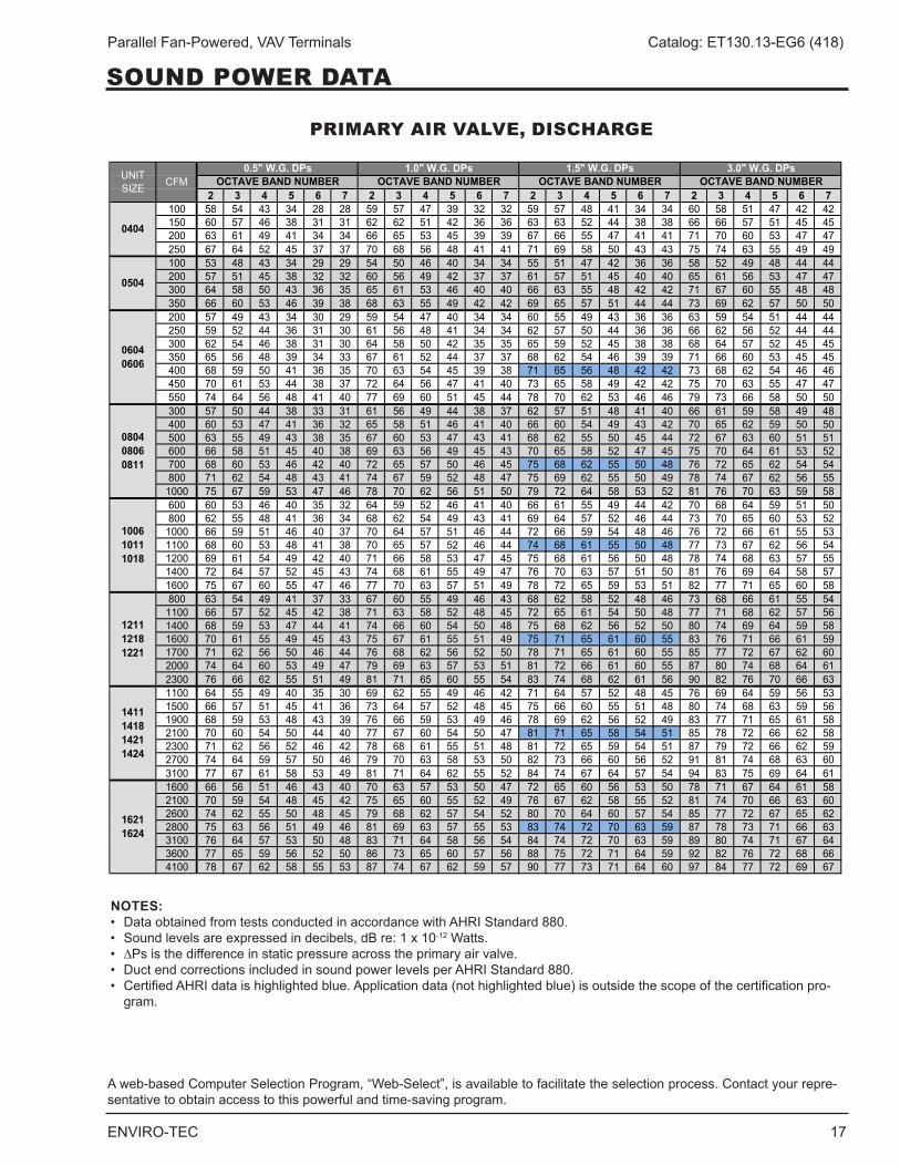
PRIMARY AIR VALVE, DISCHARGE
2 3 4 5 6 7 2 3 4 5 6 7 2 3 4 5 6 7 2 3 4 5 6 7100 58 54 43 34 28 28 59 57 47 39 32 32 59 57 48 41 34 34 60 58 51 47 42 42150 60 57 46 38 31 31 62 62 51 42 36 36 63 63 52 44 38 38 66 66 57 51 45 45200 63 61 49 41 34 34 66 65 53 45 39 39 67 66 55 47 41 41 71 70 60 53 47 47250 67 64 52 45 37 37 70 68 56 48 41 41 71 69 58 50 43 43 75 74 63 55 49 49100 53 48 43 34 29 29 54 50 46 40 34 34 55 51 47 42 36 36 58 52 49 48 44 44200 57 51 45 38 32 32 60 56 49 42 37 37 61 57 51 45 40 40 65 61 56 53 47 47300 64 58 50 43 36 35 65 61 53 46 40 40 66 63 55 48 42 42 71 67 60 55 48 48350 66 60 53 46 39 38 68 63 55 49 42 42 69 65 57 51 44 44 73 69 62 57 50 50200 57 49 43 34 30 29 59 54 47 40 34 34 60 55 49 43 36 36 63 59 54 51 44 44250 59 52 44 36 31 30 61 56 48 41 34 34 62 57 50 44 36 36 66 62 56 52 44 44300 62 54 46 38 31 30 64 58 50 42 35 35 65 59 52 45 38 38 68 64 57 52 45 45350 65 56 48 39 34 33 67 61 52 44 37 37 68 62 54 46 39 39 71 66 60 53 45 45400 68 59 50 41 36 35 70 63 54 45 39 38 71 65 56 48 42 42 73 68 62 54 46 46450 70 61 53 44 38 37 72 64 56 47 41 40 73 65 58 49 42 42 75 70 63 55 47 47550 74 64 56 48 41 40 77 69 60 51 45 44 78 70 62 53 46 46 79 73 66 58 50 50300 57 50 44 38 33 31 61 56 49 44 38 37 62 57 51 48 41 40 66 61 59 58 49 48400 60 53 47 41 36 32 65 58 51 46 41 40 66 60 54 49 43 42 70 65 62 59 50 50500 63 55 49 43 38 35 67 60 53 47 43 41 68 62 55 50 45 44 72 67 63 60 51 51600 66 58 51 45 40 38 69 63 56 49 45 43 70 65 58 52 47 45 75 70 64 61 53 52700 68 60 53 46 42 40 72 65 57 50 46 45 75 68 62 55 50 48 76 72 65 62 54 54800 71 62 54 48 43 41 74 67 59 52 48 47 75 69 62 55 50 49 78 74 67 62 56 551000 75 67 59 53 47 46 78 70 62 56 51 50 79 72 64 58 53 52 81 76 70 63 59 58600 60 53 46 40 35 32 64 59 52 46 41 40 66 61 55 49 44 42 70 68 64 59 51 50800 62 55 48 41 36 34 68 62 54 49 43 41 69 64 57 52 46 44 73 70 65 60 53 521000 66 59 51 46 40 37 70 64 57 51 46 44 72 66 59 54 48 46 76 72 66 61 55 531100 68 60 53 48 41 38 70 65 57 52 46 44 74 68 61 55 50 48 77 73 67 62 56 541200 69 61 54 49 42 40 71 66 58 53 47 45 75 68 61 56 50 48 78 74 68 63 57 551400 72 64 57 52 45 43 74 68 61 55 49 47 76 70 63 57 51 50 81 76 69 64 58 571600 75 67 60 55 47 46 77 70 63 57 51 49 78 72 65 59 53 51 82 77 71 65 60 58800 63 54 49 41 37 33 67 60 55 49 46 43 68 62 58 52 48 46 73 68 66 61 55 541100 66 57 52 45 42 38 71 63 58 52 48 45 72 65 61 54 50 48 77 71 68 62 57 561400 68 59 53 47 44 41 74 66 60 54 50 48 75 68 62 56 52 50 80 74 69 64 59 581600 70 61 55 49 45 43 75 67 61 55 51 49 75 71 65 61 60 55 83 76 71 66 61 591700 71 62 56 50 46 44 76 68 62 56 52 50 78 71 65 61 60 55 85 77 72 67 62 602000 74 64 60 53 49 47 79 69 63 57 53 51 81 72 66 61 60 55 87 80 74 68 64 612300 76 66 62 55 51 49 81 71 65 60 55 54 83 74 68 62 61 56 90 82 76 70 66 631100 64 55 49 40 35 30 69 62 55 49 46 42 71 64 57 52 48 45 76 69 64 59 56 531500 66 57 51 45 41 36 73 64 57 52 48 45 75 66 60 55 51 48 80 74 68 63 59 561900 68 59 53 48 43 39 76 66 59 53 49 46 78 69 62 56 52 49 83 77 71 65 61 582100 70 60 54 50 44 40 77 67 60 54 50 47 81 71 65 58 54 51 85 78 72 66 62 582300 71 62 56 52 46 42 78 68 61 55 51 48 81 72 65 59 54 51 87 79 72 66 62 592700 74 64 59 57 50 46 79 70 63 58 53 50 82 73 66 60 56 52 91 81 74 68 63 603100 77 67 61 58 53 49 81 71 64 62 55 52 84 74 67 64 57 54 94 83 75 69 64 611600 66 56 51 46 43 40 70 63 57 53 50 47 72 65 60 56 53 50 78 71 67 64 61 582100 70 59 54 48 45 42 75 65 60 55 52 49 76 67 62 58 55 52 81 74 70 66 63 602600 74 62 55 50 48 45 79 68 62 57 54 52 80 70 64 60 57 54 85 77 72 67 65 622800 75 63 56 51 49 46 81 69 63 57 55 53 83 74 72 70 63 59 87 78 73 71 66 633100 76 64 57 53 50 48 83 71 64 58 56 54 84 74 72 70 63 59 89 80 74 71 67 643600 77 65 59 56 52 50 86 73 65 60 57 56 88 75 72 71 64 59 92 82 76 72 68 664100 78 67 62 58 55 53 87 74 67 62 59 57 90 77 73 71 64 60 97 84 77 72 69 67
UNIT SIZE CFM
0.5" W.G. DPs 1.0" W.G. DPs 3.0" W.G. DPsOCTAVE BAND NUMBER OCTAVE BAND NUMBER OCTAVE BAND NUMBER
1411141814211424
16211624
1.5" W.G. DPsOCTAVE BAND NUMBER
0404
0504
06040606
080408060811
100610111018
121112181221
NOTES:• DataobtainedfromtestsconductedinaccordancewithAHRIStandard880.• Soundlevelsareexpressedindecibels,dBre:1x10-12 Watts .• ∆Ps is the difference in static pressure across the primary air valve .• DuctendcorrectionsincludedinsoundpowerlevelsperAHRIStandard880.• CertifiedAHRIdataishighlightedblue.Applicationdata(nothighlightedblue)isoutsidethescopeofthecertificationpro- gram .
A web-based Computer Selection Program, “Web-Select”, is available to facilitate the selection process . Contact your repre-sentative to obtain access to this powerful and time-saving program .
SOUND POWER DATA
18 ENVIRO-TEC
Parallel Fan-Powered, VAV Terminals Catalog: ET130.13-EG6 (418)
SOUND POWER DATA
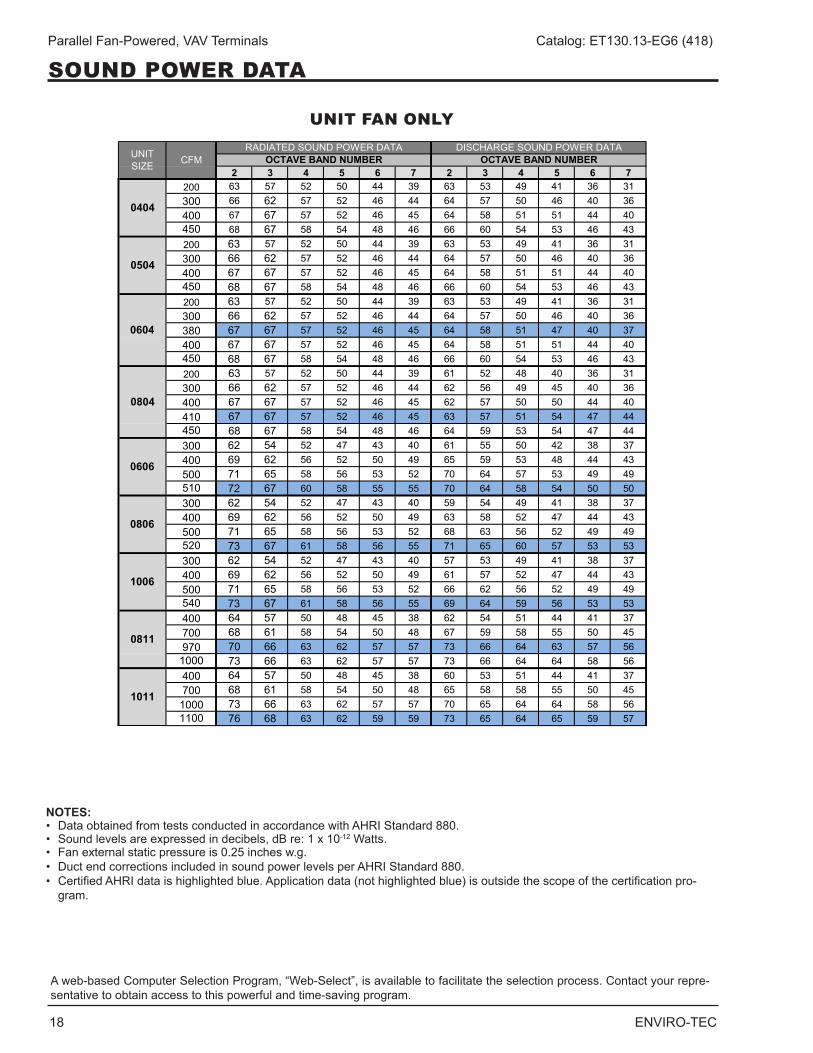
A web-based Computer Selection Program, “Web-Select”, is available to facilitate the selection process . Contact your repre-sentative to obtain access to this powerful and time-saving program .
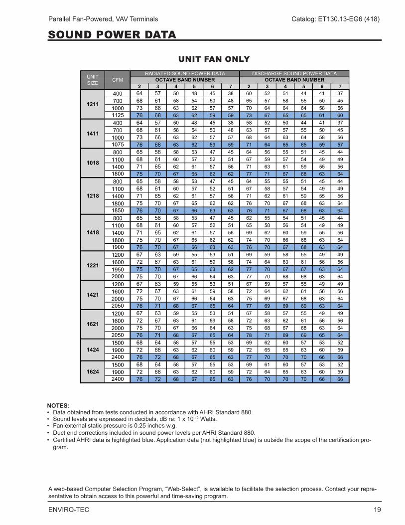
UNIT FAN ONLY
2 3 4 5 6 7 2 3 4 5 6 7200 63 57 52 50 44 39 63 53 49 41 36 31300 66 62 57 52 46 44 64 57 50 46 40 36400 67 67 57 52 46 45 64 58 51 51 44 40450 68 67 58 54 48 46 66 60 54 53 46 43200 63 57 52 50 44 39 63 53 49 41 36 31300 66 62 57 52 46 44 64 57 50 46 40 36400 67 67 57 52 46 45 64 58 51 51 44 40450 68 67 58 54 48 46 66 60 54 53 46 43200 63 57 52 50 44 39 63 53 49 41 36 31300 66 62 57 52 46 44 64 57 50 46 40 36380 67 67 57 52 46 45 64 58 51 47 40 37400 67 67 57 52 46 45 64 58 51 51 44 40450 68 67 58 54 48 46 66 60 54 53 46 43200 63 57 52 50 44 39 61 52 48 40 36 31300 66 62 57 52 46 44 62 56 49 45 40 36400 67 67 57 52 46 45 62 57 50 50 44 40410 67 67 57 52 46 45 63 57 51 54 47 44450 68 67 58 54 48 46 64 59 53 54 47 44300 62 54 52 47 43 40 61 55 50 42 38 37400 69 62 56 52 50 49 65 59 53 48 44 43500 71 65 58 56 53 52 70 64 57 53 49 49510 72 67 60 58 55 55 70 64 58 54 50 50300 62 54 52 47 43 40 59 54 49 41 38 37400 69 62 56 52 50 49 63 58 52 47 44 43500 71 65 58 56 53 52 68 63 56 52 49 49520 73 67 61 58 56 55 71 65 60 57 53 53300 62 54 52 47 43 40 57 53 49 41 38 37400 69 62 56 52 50 49 61 57 52 47 44 43500 71 65 58 56 53 52 66 62 56 52 49 49540 73 67 61 58 56 55 69 64 59 56 53 53400 64 57 50 48 45 38 62 54 51 44 41 37700 68 61 58 54 50 48 67 59 58 55 50 45970 70 66 63 62 57 57 73 66 64 63 57 56
1000 73 66 63 62 57 57 73 66 64 64 58 56400 64 57 50 48 45 38 60 53 51 44 41 37700 68 61 58 54 50 48 65 58 58 55 50 45
1000 73 66 63 62 57 57 70 65 64 64 58 561100 76 68 63 62 59 59 73 65 64 65 59 57
UNIT SIZE CFM
RADIATED SOUND POWER DATA DISCHARGE SOUND POWER DATAOCTAVE BAND NUMBER OCTAVE BAND NUMBER
0404
0504
0604
0804
0606
0806
1006
0811
1011
NOTES:• DataobtainedfromtestsconductedinaccordancewithAHRIStandard880.• Soundlevelsareexpressedindecibels,dBre:1x10-12 Watts .• Fanexternalstaticpressureis0.25inchesw.g.• DuctendcorrectionsincludedinsoundpowerlevelsperAHRIStandard880.• CertifiedAHRIdataishighlightedblue.Applicationdata(nothighlightedblue)isoutsidethescopeofthecertificationpro- gram .
ENVIRO-TEC 19
Parallel Fan-Powered, VAV Terminals Catalog: ET130.13-EG6 (418)
A web-based Computer Selection Program, “Web-Select”, is available to facilitate the selection process . Contact your repre-sentative to obtain access to this powerful and time-saving program .
NOTES:• DataobtainedfromtestsconductedinaccordancewithAHRIStandard880.• Soundlevelsareexpressedindecibels,dBre:1x10-12 Watts .• Fanexternalstaticpressureis0.25inchesw.g.• DuctendcorrectionsincludedinsoundpowerlevelsperAHRIStandard880.• CertifiedAHRIdataishighlightedblue.Applicationdata(nothighlightedblue)isoutsidethescopeofthecertificationpro- gram .
UNIT FAN ONLY
2 3 4 5 6 7 2 3 4 5 6 7400 64 57 50 48 45 38 60 52 51 44 41 37700 68 61 58 54 50 48 65 57 58 55 50 45
1000 73 66 63 62 57 57 70 64 64 64 58 561125 76 68 63 62 59 59 73 67 65 65 61 60400 64 57 50 48 45 38 58 52 50 44 41 37700 68 61 58 54 50 48 63 57 57 55 50 45
1000 73 66 63 62 57 57 68 64 63 64 58 561075 76 68 63 62 59 59 71 64 65 65 59 57800 65 58 58 53 47 45 64 56 55 51 45 44
1100 68 61 60 57 52 51 67 59 57 54 49 491400 71 65 62 61 57 56 71 63 61 59 55 561800 75 70 67 65 62 62 77 71 67 68 63 64800 65 58 58 53 47 45 64 55 55 51 45 44
1100 68 61 60 57 52 51 67 58 57 54 49 491400 71 65 62 61 57 56 71 62 61 59 55 561800 75 70 67 65 62 62 76 70 67 68 63 641850 76 70 67 66 63 63 76 71 67 68 63 64800 65 58 58 53 47 45 62 55 54 51 45 44
1100 68 61 60 57 52 51 65 58 56 54 49 491400 71 65 62 61 57 56 69 62 60 59 55 561800 75 70 67 65 62 62 74 70 66 68 63 641900 76 70 67 66 63 63 76 70 67 68 63 641200 67 63 59 55 53 51 69 59 58 55 49 491600 72 67 63 61 59 58 74 64 63 61 56 561950 75 70 67 65 63 62 77 70 67 67 63 642000 75 70 67 66 64 63 77 70 68 68 63 641200 67 63 59 55 53 51 67 59 57 55 49 491600 72 67 63 61 59 58 72 64 62 61 56 562000 75 70 67 66 64 63 75 69 67 68 63 642050 76 71 68 67 65 64 77 69 69 69 63 641200 67 63 59 55 53 51 67 58 57 55 49 491600 72 67 63 61 59 58 72 63 62 61 56 562000 75 70 67 66 64 63 75 68 67 68 63 642050 76 71 68 67 65 64 78 71 69 69 65 641500 68 64 58 57 55 53 69 62 60 57 53 521900 72 68 63 62 60 59 72 65 65 63 60 592400 76 72 68 67 65 63 77 70 70 70 66 661500 68 64 58 57 55 53 69 61 60 57 53 521900 72 68 63 62 60 59 72 64 65 63 60 592400 76 72 68 67 65 63 76 70 70 70 66 66
1624
1218
1418
1221
1421
1621
1424
1211
1411
1018
UNIT SIZE CFM
RADIATED SOUND POWER DATA DISCHARGE SOUND POWER DATAOCTAVE BAND NUMBER OCTAVE BAND NUMBER
SOUND POWER DATA
20 ENVIRO-TEC
Parallel Fan-Powered, VAV Terminals Catalog: ET130.13-EG6 (418)
FAN PERFORMANCE DATA, PSC MOTOR
GENERAL FAN NOTE
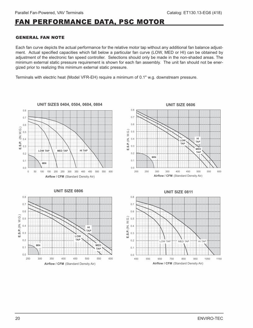
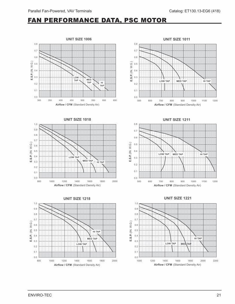
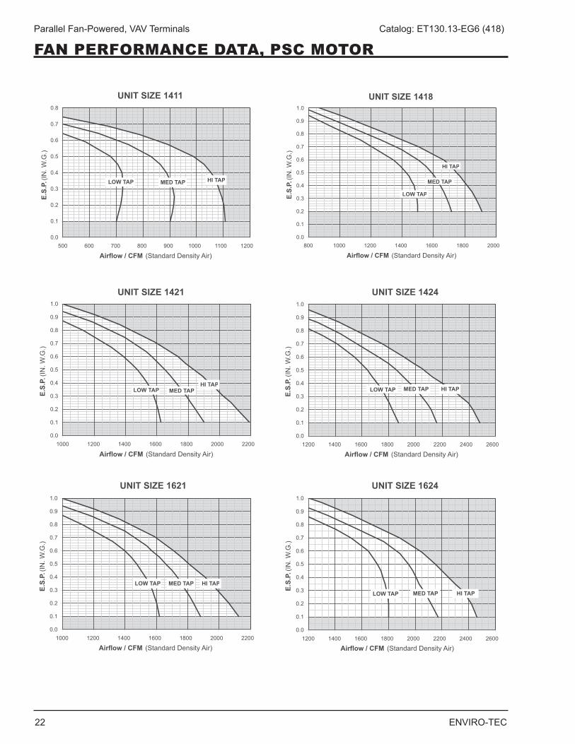
Each fan curve depicts the actual performance for the relative motor tap without any additional fan balance adjust-ment.Actualspecifiedcapacitieswhichfallbelowaparticularfancurve(LOW,MEDorHI)canbeobtainedbyadjustment of the electronic fan speed controller . Selections should only be made in the non-shaded areas . The minimum external static pressure requirement is shown for each fan assembly . The unit fan should not be ener-gized prior to realizing this minimum external static pressure .
Terminals with electric heat (Model VFR-EH) require a minimum of 0 .1" w .g . downstream pressure .
UNIT SIZES 0404, 0504, 0604, 0804
0.0
0.1
0.2
0.3
0.4
0.5
0.6
0.7
0.8
0 50 100 150 200 250 300 350 400 450 500 550 600
Airflow / CFM (Standard Density Air)
E.S.
P. (
IN. W
.G.)
HI TAPMED TAPLOW TAP
MIN
UNIT SIZE 0811
0.0
0.1
0.2
0.3
0.4
0.5
0.6
0.7
0.8
450 550 650 750 850 950 1050 1150
Airflow / CFM (Standard Density Air)
E.S.
P. (I
N. W
.G.)
HI TAPMED TAPLOW TAP
UNIT SIZE 0606
0.0
0.1
0.2
0.3
0.4
0.5
0.6
0.7
0.8
200 250 300 350 400 450 500 550 600
Airflow / CFM (Standard Density Air)
E.S.
P. (I
N. W
.G.)
HITAP
MEDTAP
LOWTAP
MIN
UNIT SIZE 0806
0.0
0.1
0.2
0.3
0.4
0.5
0.6
0.7
0.8
250 300 350 400 450 500 550 600
Airflow / CFM (Standard Density Air)
E.S.
P. (I
N. W
.G.)
HITAP
MEDTAP
LOWTAP
MIN
ENVIRO-TEC 21
Parallel Fan-Powered, VAV Terminals Catalog: ET130.13-EG6 (418)
UNIT SIZE 1006
0.0
0.1
0.2
0.3
0.4
0.5
0.6
0.7
0.8
300 350 400 450 500 550 600 650
Airflow / CFM (Standard Density Air)
E.S.
P. (I
N. W
.G.)
HITAP
MEDTAP
LOWTAP
UNIT SIZE 1018
0.0
0.1
0.2
0.3
0.4
0.5
0.6
0.7
0.8
0.9
1.0
800 1000 1200 1400 1600 1800 2000
Airflow / CFM (Standard Density Air)
E.S.
P. (I
N. W
.G.)
HI TAPMED TAPLOW TAP
UNIT SIZE 1218
0.0
0.1
0.2
0.3
0.4
0.5
0.6
0.7
0.8
0.9
1.0
800 1000 1200 1400 1600 1800 20000.0
0.1
0.2
0.3
0.4
0.5
0.6
0.7
0.8
0.9
1.0
1000 1200 1400 1600 1800 2000 2200
Airflow / CFM (Standard Density Air)
E.S.
P. (
IN. W
.G.)
HI TAP
MED TAP
LOW TAP
UNIT SIZE 1011
0.0
0.1
0.2
0.3
0.4
0.5
0.6
0.7
0.8
500 600 700 800 900 1000 1100 1200
Airflow / CFM (Standard Density Air)
E.S.
P. (I
N. W
.G.)
HI TAPMED TAPLOW TAP
UNIT SIZE 1211
0.0
0.1
0.2
0.3
0.4
0.5
0.6
0.7
0.8
500 600 700 800 900 1000 1100 1200
Airflow / CFM (Standard Density Air)
E.S.
P. (I
N. W
.G.)
HI TAPMED TAPLOW TAP
UNIT SIZE 1221
Airflow / CFM (Standard Density Air)
E.S.
P. (I
N. W
.G.)
HI TAP
MED TAPLOW TAP
FAN PERFORMANCE DATA, PSC MOTOR
22 ENVIRO-TEC
Parallel Fan-Powered, VAV Terminals Catalog: ET130.13-EG6 (418)
FAN PERFORMANCE DATA, PSC MOTOR
UNIT SIZE 1411
0.0
0.1
0.2
0.3
0.4
0.5
0.6
0.7
0.8
500 600 700 800 900 1000 1100 1200
Airflow / CFM (Standard Density Air)
E.S.
P. (I
N. W
.G.)
HI TAPMED TAPLOW TAP
UNIT SIZE 1421
0.0
0.1
0.2
0.3
0.4
0.5
0.6
0.7
0.8
0.9
1.0
1000 1200 1400 1600 1800 2000 2200
Airflow / CFM (Standard Density Air)
E.S.
P. (I
N. W
.G.)
HI TAPMED TAPLOW TAP
UNIT SIZE 1621
0.0
0.1
0.2
0.3
0.4
0.5
0.6
0.7
0.8
0.9
1.0
1000 1200 1400 1600 1800 2000 2200
Airflow / CFM (Standard Density Air)
E.S.
P. (I
N. W
.G.)
HI TAPMED TAPLOW TAP
UNIT SIZE 1418
0.0
0.1
0.2
0.3
0.4
0.5
0.6
0.7
0.8
0.9
1.0
800 1000 1200 1400 1600 1800 2000
Airflow / CFM (Standard Density Air)
E.S.
P. (I
N. W
.G.)
HI TAP
MED TAP
LOW TAP
UNIT SIZE 1424
0.0
0.1
0.2
0.3
0.4
0.5
0.6
0.7
0.8
0.9
1.0
1200 1400 1600 1800 2000 2200 2400 2600
Airflow / CFM (Standard Density Air)
E.S.
P. (I
N. W
.G.)
HI TAPMED TAPLOW TAP
UNIT SIZE 1624
0.0
0.1
0.2
0.3
0.4
0.5
0.6
0.7
0.8
0.9
1.0
1200 1400 1600 1800 2000 2200 2400 2600
Airflow / CFM (Standard Density Air)
E.S.
P. (I
N. W
.G.)
HI TAPMED TAPLOW TAP
ENVIRO-TEC 23
Parallel Fan-Powered, VAV Terminals Catalog: ET130.13-EG6 (418)
EC FAN MOTOR OPTIONTHE ENERGY EFFICIENT SOLUTION
ENVIRO-TEC offers an alternative to the PSC motor that significantly increases the operating efficiency of fan terminal units . This motor is frequently referred to as an ECM (electronically commutated motor) . It is a brushlessDC(BLDC)motorutilizingapermanentmag-net rotor . The motor has been in production for years and is commonly used in residential HVAC units . Fan speed control is accomplished through a microproces-sor based variable speed controller (inverter) integral to the motor . The motor provides peak efficiency rat-ings between 70 & 80% for most applications .
ECM FEATURES AND BENEFITS
Ultra-High Motor & Controller Energy EfficiencyDC motors are significantly more efficient than AC motors . At full load the EC motor is typically 20% more efficient than a standard induction motor . Due to acous-tical considerations, the fan motor on a fan powered terminal typically operates considerably less than full load . At this condition the overall motor / controller (SCR) efficiency can be cut in half . Due to the perma-nent magnet, DC design, the EC motor maintains a high efficiency at low speeds . Most fan powered unit selec-tions will have an overall efficiency greater than 75% . Furthermore, the motor heat gain is greatly reduced providing additional energy savings by reducing the cold primary air requirement .
Pressure Independent Fan VolumeThe integral microprocessor based controller includes a feature that provides sensorless (no external feedback) constant airflow operation by automatically adjusting the speed and torque in response to system pressure changes . This breakthrough will no doubt have far reach-ing benefits and endless applications . For starters, the fan volume supplied to the space will not significantly change as a filter becomes loaded . This provides new opportunities for medical applications where space pres-surization and HEPA filters are applied . The air balance process will become simpler and more accurate since the fan volume will not need to be re-adjusted after the diffuser balance is accomplished .
Factory Calibrated Fan VolumeDue to the pressure independent feature, the fan capacity can now be calibrated at the factory . Within the published external pressure limits, the fan motor will automatically adjust to account for the varying static pressure requirements associated with different downstream duct configurations . This feature should not preclude the final field air balance verification pro-cess during the commissioning stage of a project . An electronic (PWM) speed control device is provided to
allow field changes of the fan capacity as the need arises . Fan volume can be field calibrated in two fash-ions depending on the type of PWM control board provided on the unit . For the Solo PWM board, a poten-tiometer is provided allowing manual adjustment using an instrument type screwdriver . If a Sync PWM board is provided, the fan volume can be calibrated through the BMS using an analog output (2 to10VDC typical) to the speed controller . A fan volume versus DC volts calibration chart is provided .
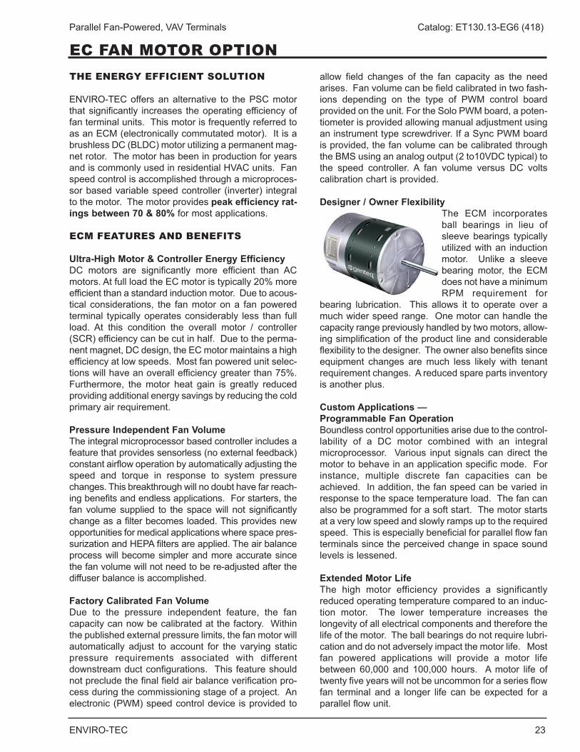
Designer / Owner FlexibilityThe ECM incorporates ball bearings in lieu of sleeve bearings typically utilized with an induction motor . Unlike a sleeve bearing motor, the ECM does not have a minimum RPM requirement for
bearing lubrication . This allows it to operate over a much wider speed range . One motor can handle the capacity range previously handled by two motors, allow-ing simplification of the product line and considerable flexibility to the designer . The owner also benefits since equipment changes are much less likely with tenant requirement changes . A reduced spare parts inventory is another plus .
Custom Applications — Programmable Fan Operation Boundless control opportunities arise due to the control-lability of a DC motor combined with an integral microprocessor . Various input signals can direct the motor to behave in an application specific mode . For instance, multiple discrete fan capacities can be achieved . In addition, the fan speed can be varied in response to the space temperature load . The fan can also be programmed for a soft start . The motor starts at a very low speed and slowly ramps up to the required speed . This is especially beneficial for parallel flow fan terminals since the perceived change in space sound levels is lessened .
Extended Motor LifeThe high motor efficiency provides a significantly reduced operating temperature compared to an induc-tion motor . The lower temperature increases the longevity of all electrical components and therefore the life of the motor . The ball bearings do not require lubri-cation and do not adversely impact the motor life . Most fan powered applications will provide a motor life between 60,000 and 100,000 hours . A motor life of twenty five years will not be uncommon for a series flow fan terminal and a longer life can be expected for a parallel flow unit .
24 ENVIRO-TEC
Parallel Fan-Powered, VAV Terminals Catalog: ET130.13-EG6 (418)
GENERAL SELECTION, EC MOTOR
Dis. Rad. Dis. Rad. Dis. Rad.
200 0 .03 -- -- -- -- -- 22250 0 .04 -- -- -- -- -- 24300 0 .06 -- -- -- -- -- 25350 0 .08 -- -- -- 20 -- 28450 0 .14 -- 22 -- 25 24 32 240 2 .8500 0 .04 - - - 22 23 33600 0 .01 - - - 24 24 32300 0 .01 -- -- -- -- -- 29400 0 .03 -- -- -- 20 -- 32500 0 .04 -- -- -- 23 22 33600 0 .06 -- 22 -- 25 25 35700 0 .07 - 24 20 27 27 37800 0 .1 -- 27 20 30 29 381000 0 .15 20 32 24 35 32 401100 0 .02 - 24 - 28 28 37600 0 .01 - - - 24 24 32800 0 .01 - 23 - 27 25 351000 0 .01 - 25 - 29 28 37 208 51200 0 .02 - 29 20 32 30 40 240 4 .31400 0 .02 - 33 23 33 33 421600 0 .03 22 34 25 35 34 44800 0 .01 - 20 - 24 24 341100 0 .02 - 24 - 28 28 371400 0 .04 - 28 22 32 32 40 208 7 .31500 0 .04 - 22 20 28 32 401700 0 .06 - 32 24 34 35 452000 0 .08 - 35 25 38 38 482300 0 .10 22 37 28 40 40 501100 0 .02 - - - 23 25 331600 0 .01 - 24 - 33 29 422100 0 .02 - 28 23 37 33 472600 0 .03 22 30 28 39 36 493100 0 .04 24 35 33 42 40 503600 0 .05 25 37 37 43 44 544100 0 .07 27 38 38 45 50 57 277 6 .9
Volts FLA3.0" w.g. Δ P
120 5
208 3
277 4 .1
277 4 .1
120
240 9 .1
101812181418
06
18
21
ROOM NOISE CRITERIA (NC)
0.5" w.g. Δ P 1.0" w.g. Δ P
0606 1/3
1/2
0811 1011 1211
1/211
Unit Size CFM Fan Size Min delta P's (IN.W.G.) Fan HP
0806
6 .8240
9 .4241424
1624
1221 1421 1621
3/4
1
7 .7
120 5 9 .6
208
277 5 .5
120 5 12 .8
PRIMARY AIR VALVE
277 2 .6
120 7 .7
208 5
240 4 .3
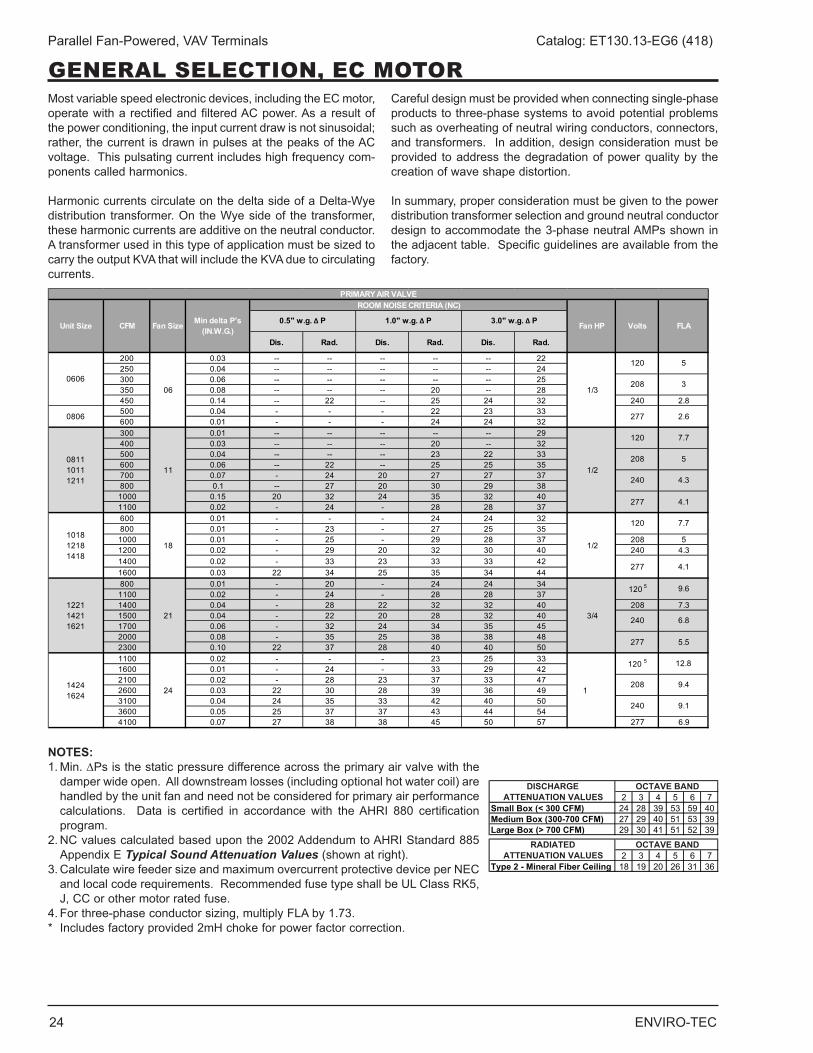
Most variable speed electronic devices, including the EC motor, operate with a rectified and filtered AC power . As a result of the power conditioning, the input current draw is not sinusoidal; rather, the current is drawn in pulses at the peaks of the AC voltage . This pulsating current includes high frequency com-ponents called harmonics .
Harmonic currents circulate on the delta side of a Delta-Wye distribution transformer . On the Wye side of the transformer, these harmonic currents are additive on the neutral conductor . A transformer used in this type of application must be sized to carry the output KVA that will include the KVA due to circulating currents .
Careful design must be provided when connecting single-phase products to three-phase systems to avoid potential problems such as overheating of neutral wiring conductors, connectors, and transformers . In addition, design consideration must be provided to address the degradation of power quality by the creation of wave shape distortion .
In summary, proper consideration must be given to the power distribution transformer selection and ground neutral conductor design to accommodate the 3-phase neutral AMPs shown in the adjacent table . Specific guidelines are available from the factory .
NOTES:1 . Min . ∆Ps is the static pressure difference across the primary air valve with the
damper wide open . All downstream losses (including optional hot water coil) are handled by the unit fan and need not be considered for primary air performance calculations . Data is certified in accordance with the AHRI 880 certification program .
2 . NC values calculated based upon the 2002 Addendum to AHRI Standard 885 Appendix E Typical Sound Attenuation Values (shown at right) .
3 . Calculate wire feeder size and maximum overcurrent protective device per NEC andlocalcoderequirements.RecommendedfusetypeshallbeULClassRK5,J, CC or other motor rated fuse .
4.Forthree-phaseconductorsizing,multiplyFLAby1.73.* Includes factory provided 2mH choke for power factor correction .
2 3 4 5 6 7Small Box (< 300 CFM) 24 28 39 53 59 40Medium Box (300-700 CFM) 27 29 40 51 53 39Large Box (> 700 CFM) 29 30 41 51 52 39
2 3 4 5 6 7Type 2 - Mineral Fiber Ceiling 18 19 20 26 31 36
OCTAVE BAND
OCTAVE BANDRADIATED ATTENUATION VALUES
DISCHARGE ATTENUATION VALUES
ENVIRO-TEC 25
Parallel Fan-Powered, VAV Terminals Catalog: ET130.13-EG6 (418)
FAN PERFORMANCE, EC MOTOR
GENERAL FAN NOTE
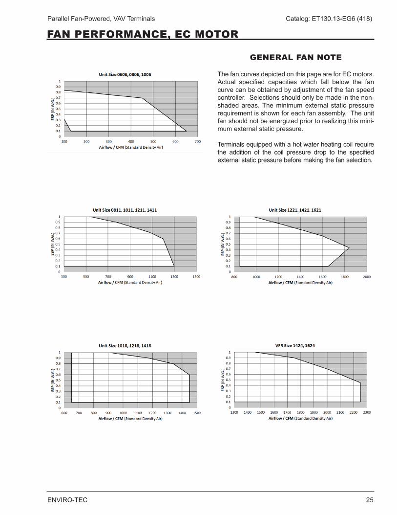
The fan curves depicted on this page are for EC motors . Actual specified capacities which fall below the fan curve can be obtained by adjustment of the fan speed controller . Selections should only be made in the non-shaded areas . The minimum external static pressure requirement is shown for each fan assembly . The unit fan should not be energized prior to realizing this mini-mum external static pressure .
Terminals equipped with a hot water heating coil require the addition of the coil pressure drop to the specified external static pressure before making the fan selection .
26 ENVIRO-TEC
Parallel Fan-Powered, VAV Terminals Catalog: ET130.13-EG6 (418)
AHRI RATINGS
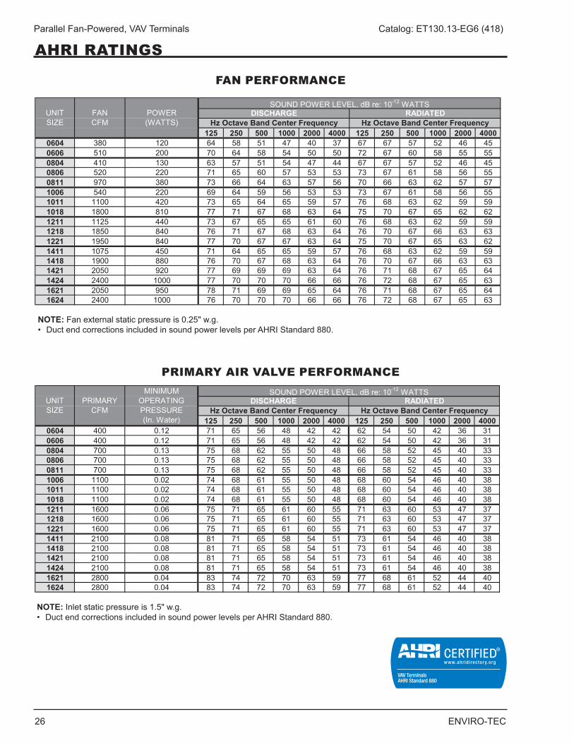
FAN PERFORMANCE
PRIMARY AIR VALVE PERFORMANCE
125 250 500 1000 2000 4000 125 250 500 1000 2000 40000604 380 120 64 58 51 47 40 37 67 67 57 52 46 450606 510 200 70 64 58 54 50 50 72 67 60 58 55 550804 410 130 63 57 51 54 47 44 67 67 57 52 46 450806 520 220 71 65 60 57 53 53 73 67 61 58 56 550811 970 380 73 66 64 63 57 56 70 66 63 62 57 571006 540 220 69 64 59 56 53 53 73 67 61 58 56 551011 1100 420 73 65 64 65 59 57 76 68 63 62 59 591018 1800 810 77 71 67 68 63 64 75 70 67 65 62 621211 1125 440 73 67 65 65 61 60 76 68 63 62 59 591218 1850 840 76 71 67 68 63 64 76 70 67 66 63 631221 1950 840 77 70 67 67 63 64 75 70 67 65 63 621411 1075 450 71 64 65 65 59 57 76 68 63 62 59 591418 1900 880 76 70 67 68 63 64 76 70 67 66 63 631421 2050 920 77 69 69 69 63 64 76 71 68 67 65 641424 2400 1000 77 70 70 70 66 66 76 72 68 67 65 631621 2050 950 78 71 69 69 65 64 76 71 68 67 65 641624 2400 1000 76 70 70 70 66 66 76 72 68 67 65 63
UNIT SIZE
FAN CFM
POWER (WATTS)
SOUND POWER LEVEL, dB re: 10-12 WATTSDISCHARGE RADIATED
Hz Octave Band Center Frequency Hz Octave Band Center Frequency
125 250 500 1000 2000 4000 125 250 500 1000 2000 40000604 400 0.12 71 65 56 48 42 42 62 54 50 42 36 310606 400 0.12 71 65 56 48 42 42 62 54 50 42 36 310804 700 0.13 75 68 62 55 50 48 66 58 52 45 40 330806 700 0.13 75 68 62 55 50 48 66 58 52 45 40 330811 700 0.13 75 68 62 55 50 48 66 58 52 45 40 331006 1100 0.02 74 68 61 55 50 48 68 60 54 46 40 381011 1100 0.02 74 68 61 55 50 48 68 60 54 46 40 381018 1100 0.02 74 68 61 55 50 48 68 60 54 46 40 381211 1600 0.06 75 71 65 61 60 55 71 63 60 53 47 371218 1600 0.06 75 71 65 61 60 55 71 63 60 53 47 371221 1600 0.06 75 71 65 61 60 55 71 63 60 53 47 371411 2100 0.08 81 71 65 58 54 51 73 61 54 46 40 381418 2100 0.08 81 71 65 58 54 51 73 61 54 46 40 381421 2100 0.08 81 71 65 58 54 51 73 61 54 46 40 381424 2100 0.08 81 71 65 58 54 51 73 61 54 46 40 381621 2800 0.04 83 74 72 70 63 59 77 68 61 52 44 401624 2800 0.04 83 74 72 70 63 59 77 68 61 52 44 40
UNIT SIZE
PRIMARY CFM
MINIMUM OPERATING PRESSURE (In. Water)
SOUND POWER LEVEL, dB re: 10-12 WATTSDISCHARGE RADIATED
Hz Octave Band Center Frequency Hz Octave Band Center Frequency
NOTE: Inlet static pressure is 1 .5" w .g .• DuctendcorrectionsincludedinsoundpowerlevelsperAHRIStandard880.
NOTE: Fan external static pressure is 0 .25" w .g .• DuctendcorrectionsincludedinsoundpowerlevelsperAHRIStandard880.
ENVIRO-TEC 27
Parallel Fan-Powered, VAV Terminals Catalog: ET130.13-EG6 (418)
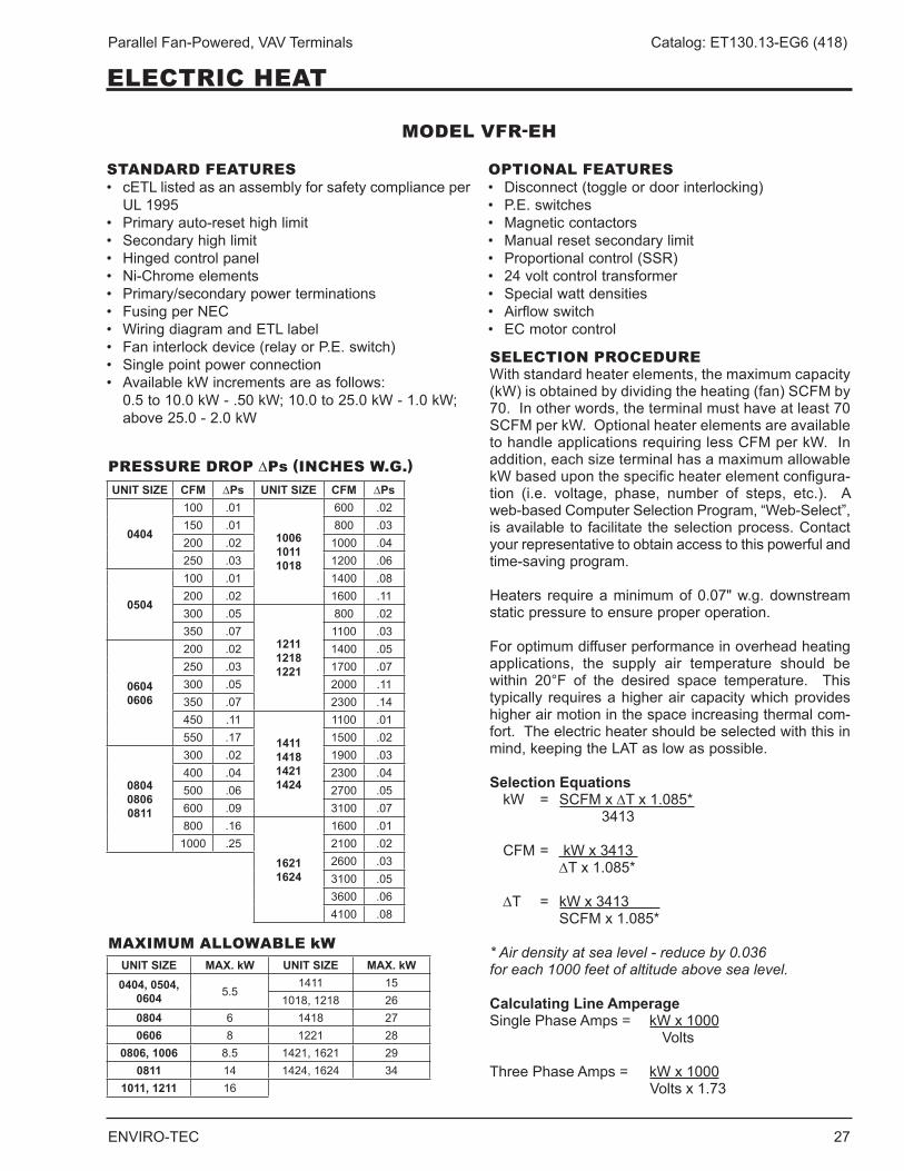
SELECTION PROCEDUREWith standard heater elements, the maximum capacity (kW) is obtained by dividing the heating (fan) SCFM by 70 . In other words, the terminal must have at least 70 SCFM per kW . Optional heater elements are available to handle applications requiring less CFM per kW . In addition, each size terminal has a maximum allowable kW based upon the specific heater element configura-tion (i .e . voltage, phase, number of steps, etc .) . A web-based Computer Selection Program, “Web-Select”, is available to facilitate the selection process . Contact your representative to obtain access to this powerful and time-saving program .
Heaters require a minimum of 0 .07" w .g . downstream static pressure to ensure proper operation .
For optimum diffuser performance in overhead heating applications, the supply air temperature should be within 20°F of the desired space temperature . This typically requires a higher air capacity which provides higher air motion in the space increasing thermal com-fort . The electric heater should be selected with this in mind,keepingtheLATaslowaspossible.
Selection Equations kW = SCFM x ∆T x 1 .085* 3413
CFM = kW x 3413 ∆T x 1 .085*
∆T = kW x 3413 SCFM x 1 .085*
* Air density at sea level - reduce by 0.036 for each 1000 feet of altitude above sea level.
Calculating Line AmperageSingle Phase Amps = kW x 1000 Volts Three Phase Amps = kW x 1000 Volts x 1 .73
PRESSURE DROP ∆Ps (INCHES W.G.)
MAXIMUM ALLOWABLE kW
MODEL VFR-EH
STANDARD FEATURES• cETLlistedasanassemblyforsafetycomplianceperUL1995
• Primaryauto-resethighlimit• Secondaryhighlimit• Hingedcontrolpanel• Ni-Chromeelements• Primary/secondarypowerterminations• FusingperNEC• WiringdiagramandETLlabel• Faninterlockdevice(relayorP.E.switch)• Singlepointpowerconnection• AvailablekWincrementsareasfollows:
0 .5 to 10 .0 kW - .50 kW; 10 .0 to 25 .0 kW - 1 .0 kW; above 25 .0 - 2 .0 kW
OPTIONAL FEATURES• Disconnect(toggleordoorinterlocking)• P.E.switches• Magneticcontactors• Manualresetsecondarylimit• Proportionalcontrol(SSR)• 24voltcontroltransformer• Specialwattdensities• Airflowswitch• ECmotorcontrol
UNIT SIZE CFM ∆Ps UNIT SIZE CFM ∆Ps
0404
100 .01
1006 1011 1018
600 .02150 .01 800 .03200 .02 1000 .04250 .03 1200 .06
0504
100 .01 1400 .08200 .02 1600 .11300 .05
1211 1218 1221
800 .02350 .07 1100 .03
0604 0606
200 .02 1400 .05250 .03 1700 .07300 .05 2000 .11350 .07 2300 .14450 .11
1411 1418 1421 1424
1100 .01550 .17 1500 .02
0804 0806 0811
300 .02 1900 .03400 .04 2300 .04500 .06 2700 .05600 .09 3100 .07800 .16
1621 1624
1600 .011000 .25 2100 .02
2600 .033100 .053600 .064100 .08
UNIT SIZE MAX. kW UNIT SIZE MAX. kW0404, 0504,
0604 5 .51411 15
1018, 1218 260804 6 1418 270606 8 1221 28
0806, 1006 8 .5 1421, 1621 290811 14 1424, 1624 34
1011, 1211 16
ELECTRIC HEAT
28 ENVIRO-TEC
Parallel Fan-Powered, VAV Terminals Catalog: ET130.13-EG6 (418)
HOT WATER COIL DATA
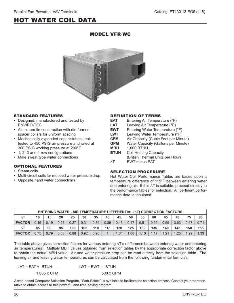
MODEL VFR-WC
STANDARD FEATURES• Designed,manufacturedandtestedby
ENVIRO-TEC• Aluminumfinconstructionwithdie-formed
spacer collars for uniform spacing• Mechanicallyexpandedcoppertubes,leak
tested to 450 PSIG air pressure and rated at 300 PSIG working pressure at 200°F
• 1,2,3and4rowconfigurations• Malesweattypewaterconnections
OPTIONAL FEATURES• Steamcoils• Multi-circuitcoilsforreducedwaterpressuredrop• Oppositehandwaterconnections
DEFINITION OF TERMSEAT Entering Air Temperature (°F)LAT LeavingAirTemperature(°F)EWT Entering Water Temperature (°F)LWT LeavingWaterTemperature(°F)CFM Air Capacity (Cubic Feet per Minute)GPM Water Capacity (Gallons per Minute)MBH 1,000 BTUHBTUH Coil Heating Capacity (British Thermal Units per Hour)∆T EWT minus EAT
SELECTION PROCEDUREHot Water Coil Performance Tables are based upon a temperature difference of 115°F between entering water and entering air . If this ∆T is suitable, proceed directly to the performance tables for selection . All pertinent perfor-mance data is tabulated .
The table above gives correction factors for various entering ∆T’s (difference between entering water and entering air temperatures) . Multiply MBH values obtained from selection tables by the appropriate correction factor above to obtain the actual MBH value . Air and water pressure drop can be read directly from the selection table . The leaving air and leaving water temperatures can be calculated from the following fundamental formulas:
LAT=EAT+ BTUH LWT=EWT-BTUH 1 .085 x CFM 500 x GPM
A web-based Computer Selection Program, “Web-Select”, is available to facilitate the selection process . Contact your represen-tative to obtain access to this powerful and time-saving program .
ENTERING WATER - AIR TEMPERATURE DIFFERENTIAL (∆T) CORRECTION FACTORS∆T 10 15 20 25 30 35 40 45 50 55 60 65 70 75 80
FACTOR 0 .15 0 .19 0 .23 0 .27 0 .31 0 .35 0 .39 0 .43 0 .47 0 .51 0 .55 0 .59 0 .63 0 .67 0 .71∆T 85 90 95 100 105 110 115 120 125 130 135 140 145 150 155
FACTOR 0 .75 0 .79 0 .83 0 .88 0 .92 0 .96 1 1 .04 1 .08 1 .13 1 .17 1 .21 1 .25 1 .29 1 .33
ENVIRO-TEC 29
Parallel Fan-Powered, VAV Terminals Catalog: ET130.13-EG6 (418)
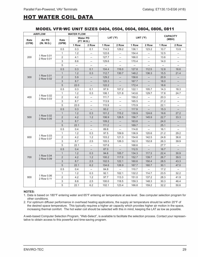
MODEL VFR-WC UNIT SIZES 0404, 0504, 0604, 0804, 0806, 0811
NOTES:1 . Data is based on 180°F entering water and 65°F entering air temperature at sea level . See computer selection program for
other conditions .2 . For optimum diffuser performance in overhead heating applications, the supply air temperature should be within 20°F of
the desired space temperature . This typically requires a higher air capacity which provides higher air motion in the space, increasingthermalcomfort.Thehotwatercoilshouldbeselectedwiththisinmind,keepingtheLATaslowaspossible.
A web-based Computer Selection Program, “Web-Select”, is available to facilitate the selection process . Contact your represen-tative to obtain access to this powerful and time-saving program .
AIRFLOW WATER FLOWLAT (°F) LWT (°F) CAPACITY
(MBH)Rate (CFM)
Air PD (IN. W.G.)
Rate (GPM)
Water PD (FT. W.G.)
1 Row 2 Row 1 Row 2 Row 1 Row 2 Row 1 Row 2 Row
200 1 Row 0 .01 2 Row 0 .01
0 .5 0 .3 0 .1 114 .5 129 .2 136 .1 123 .2 10 .7 13 .91 1 .2 -- 122 .6 -- 154 .4 -- 12 .5 --2 4 .1 -- 127 .7 -- 166 .0 -- 13 .6 --3 8 .6 -- 129 .6 -- 170 .4 -- 14 .0 --5 -- -- -- -- -- -- -- --
300 1 Row 0 .01 2 Row 0 .02
0 .5 0 .3 0 .1 104 .4 116 .0 127 .8 112 .5 12 .8 16 .61 1 .2 0 .3 112 .7 130 .7 148 .2 136 .3 15 .5 21 .42 5 .9 -- 129 .2 -- 158 .6 -- 20 .9 --3 8 .7 -- 120 .3 -- 167 .7 -- 18 .0 --5 22 .0 -- 122 .2 -- 172 .4 -- 18 .6 --
400 1 Row 0 .02 2 Row 0 .03
0 .5 0 .3 0 .1 97 .9 107 .2 122 .1 105 .7 14 .3 18 .31 1 .2 0 .3 106 .1 121 .8 143 .6 129 .7 17 .8 24 .72 4 .2 -- 111 .7 -- 159 .2 -- 20 .3 --3 8 .7 -- 113 .9 -- 165 .5 -- 21 .2 --5 22 .0 -- 115 .9 -- 170 .9 -- 22 .1 --
500 1 Row 0 .02 2 Row 0 .05
0 .5 0 .3 -- 93 .2 -- 117 .9 -- 15 .3 --1 1 .2 0 .3 101 .2 115 .2 139 .9 124 .6 19 .6 27 .22 4 .2 1 .2 106 .9 126 .5 156 .7 145 .9 22 .7 33 .33 8 .7 -- 109 .2 -- 163 .6 -- 24 .0 --5 22 .1 -- 111 .2 -- 169 .7 -- 25 .1 --
600 1 Row 0 .03 2 Row 0 .07
0 .5 0 .4 -- 89 .8 -- 114 .8 -- 16 .1 --1 1 .2 0 .3 97 .5 109 .9 136 .9 120 .6 21 .2 29 .22 4 .2 1 .2 103 .2 121 .3 154 .6 142 .5 24 .8 36 .63 8 .7 2 .5 105 .5 126 .3 162 .0 152 .8 26 .3 39 .95 22 .1 -- 107 .6 -- 168 .6 -- 27 .7 --
700 1 Row 0 .04 2 Row 0 .09
0 .5 0 .4 -- 87 .0 -- 112 .5 -- 16 .7 --1 1 .2 0 .3 94 .6 105 .7 134 .3 117 .3 22 .4 30 .92 4 .2 1 .2 100 .2 117 .0 152 .7 139 .7 26 .7 39 .53 8 .7 2 .5 102 .5 122 .1 160 .6 150 .4 28 .5 43 .35 22 .1 6 .2 104 .6 126 .9 167 .7 160 .7 30 .1 47 .0
800 1 Row 0 .06 2 Row 0 .11
0 .5 0 .4 -- 84 .8 -- 110 .7 -- 17 .2 --1 1 .2 0 .3 92 .1 102 .1 132 .2 114 .7 23 .5 32 .22 4 .2 1 .2 97 .7 113 .3 151 .0 137 .2 28 .3 41 .93 8 .8 2 .5 100 .0 118 .5 159 .3 148 .3 30 .3 46 .45 22 .1 6 .2 102 .1 123 .4 166 .8 159 .2 32 .2 50 .6
HOT WATER COIL DATA
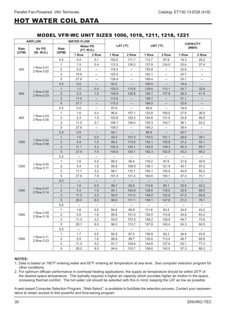
30 ENVIRO-TEC
Parallel Fan-Powered, VAV Terminals Catalog: ET130.13-EG6 (418)
HOT WATER COIL DATA
MODEL VFR-WC UNIT SIZES 1006, 1018, 1211, 1218, 1221AIRFLOW WATER FLOW
LAT (°F) LWT (°F) CAPACITY(MBH)Rate
(CFM)Air PD
(IN. W.G.)Rate
(GPM)
Water PD (FT. W.G.)
1 Row 2 Row 1 Row 2 Row 1 Row 2 Row 1 Row 2 Row
400 1 Row 0 .01 2 Row 0 .02
0 .5 0 .4 0 .1 102 .6 111 .7 113 .7 97 .9 16 .3 20 .21 1 .5 0 .4 112 .5 128 .3 137 .8 124 .0 20 .6 27 .42 5 .2 -- 119 .3 -- 155 .8 -- 23 .6 --3 10 .9 -- 122 .0 -- 163 .1 -- 24 .7 --5 27 .6 -- 124 .4 -- 169 .4 -- 25 .7 --
600 1 Row 0 .02 2 Row 0 .03
0 .5 0 .5 -- 93 .5 -- 105 .0 -- 18 .6 --1 1 .5 0 .4 103 .0 115 .6 129 .6 113 .1 24 .7 32 .92 5 .3 1 .5 109 .9 128 .8 150 .1 137 .6 29 .3 41 .53 11 .0 -- 112 .8 -- 158 .7 -- 31 .1 --5 27 .7 -- 115 .3 -- 166 .5 -- 32 .8 --
800 1 Row 0 .03 2 Row 0 .05
0 .5 0 .5 -- 87 .9 -- 99 .9 -- 19 .9 --1 1 .6 0 .4 96 .9 107 .1 123 .8 106 .0 27 .6 36 .52 5 .3 1 .5 103 .8 120 .3 145 .6 131 .0 33 .6 48 .03 11 .0 3 .1 106 .7 126 .4 155 .3 143 .7 36 .1 53 .25 27 .8 -- 109 .3 -- 164 .2 -- 38 .4 --
1000 1 Row 0 .04 2 Row 0 .08
0 .5 0 .5 -- 84 .1 -- 96 .9 -- 20 .7 --1 1 .6 0 .5 92 .5 101 .0 119 .5 101 .1 29 .8 39 .12 5 .4 1 .5 99 .3 113 .9 142 .1 125 .9 37 .2 53 .13 11 .1 3 .2 102 .2 120 .1 152 .5 139 .3 40 .3 59 .75 27 .9 7 .9 104 .8 126 .1 162 .3 152 .8 43 .2 66 .2
1200 1 Row 0 .05 2 Row 0 .11
0 .5 -- -- -- -- -- -- -- --1 1 .6 0 .5 89 .3 96 .4 116 .2 97 .6 31 .6 40 .92 5 .4 1 .5 95 .8 108 .9 139 .1 121 .9 40 .1 57 .23 11 .1 3 .2 98 .7 115 .1 150 .1 135 .6 43 .9 65 .25 27 .9 7 .9 101 .4 121 .2 160 .6 150 .1 47 .4 73 .1
1400 1 Row 0 .07 2 Row 0 .14
0 .5 -- -- -- -- -- -- -- --1 1 .6 0 .5 86 .7 92 .8 113 .6 95 .1 32 .9 42 .22 5 .4 1 .6 93 .1 104 .9 136 .6 118 .5 42 .6 60 .53 11 .2 3 .2 95 .9 111 .0 148 .0 132 .6 47 .0 69 .85 28 .0 8 .0 98 .6 117 .1 159 .1 147 .6 51 .0 78 .1
1600 1 Row 0 .09 2 Row 0 .18
0 .5 -- -- -- -- -- -- -- --1 1 .6 0 .5 84 .6 89 .9 111 .6 93 .4 34 .0 43 .22 5 .5 1 .6 90 .8 101 .5 134 .5 115 .8 44 .8 63 .43 11 .3 3 .2 93 .6 107 .5 146 .2 129 .9 49 .7 73 .85 28 .1 8 .0 96 .3 113 .7 157 .8 145 .4 54 .3 84 .5
1800 1 Row 0 .11 2 Row 0 .23
0 .5 -- -- -- -- -- -- -- --1 1 .7 0 .5 82 .9 87 .5 109 .9 92 .2 34 .9 43 .92 5 .5 1 .6 88 .9 98 .7 132 .6 113 .4 46 .7 65 .83 11 .3 3 .2 91 .7 104 .6 144 .6 127 .6 52 .1 77 .35 28 .2 8 .0 94 .4 110 .7 156 .6 143 .5 57 .3 89 .3
NOTES:1 . Data is based on 180°F entering water and 65°F entering air temperature at sea level . See computer selection program for
other conditions .2 . For optimum diffuser performance in overhead heating applications, the supply air temperature should be within 20°F of
the desired space temperature . This typically requires a higher air capacity which provides higher air motion in the space, increasingthermalcomfort.Thehotwatercoilshouldbeselectedwiththisinmind,keepingtheLATaslowaspossible.
A web-based Computer Selection Program, “Web-Select”, is available to facilitate the selection process . Contact your represen-tative to obtain access to this powerful and time-saving program .
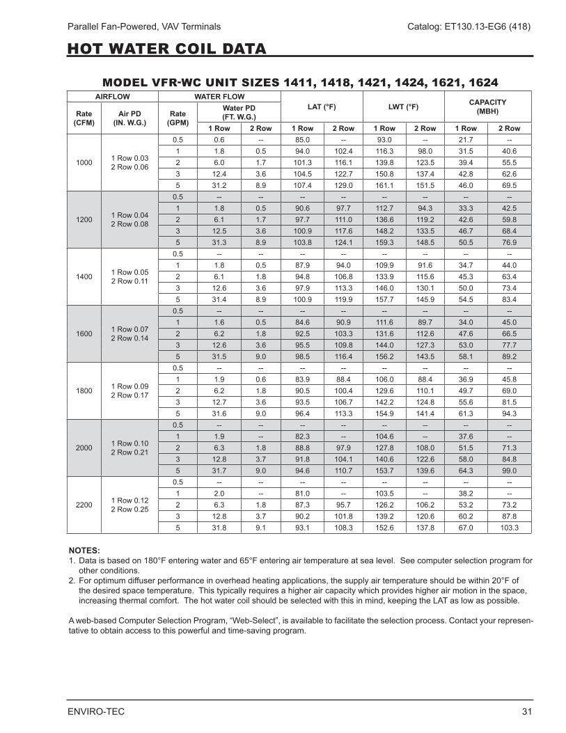
ENVIRO-TEC 31
Parallel Fan-Powered, VAV Terminals Catalog: ET130.13-EG6 (418)
MODEL VFR-WC UNIT SIZES 1411, 1418, 1421, 1424, 1621, 1624
NOTES:1 . Data is based on 180°F entering water and 65°F entering air temperature at sea level . See computer selection program for
other conditions .2 . For optimum diffuser performance in overhead heating applications, the supply air temperature should be within 20°F of
the desired space temperature . This typically requires a higher air capacity which provides higher air motion in the space, increasingthermalcomfort.Thehotwatercoilshouldbeselectedwiththisinmind,keepingtheLATaslowaspossible.
A web-based Computer Selection Program, “Web-Select”, is available to facilitate the selection process . Contact your represen-tative to obtain access to this powerful and time-saving program .
AIRFLOW WATER FLOWLAT (°F) LWT (°F) CAPACITY
(MBH)Rate (CFM)
Air PD (IN. W.G.)
Rate (GPM)
Water PD (FT. W.G.)
1 Row 2 Row 1 Row 2 Row 1 Row 2 Row 1 Row 2 Row
1000 1 Row 0 .03 2 Row 0 .06
0 .5 0 .6 -- 85 .0 -- 93 .0 -- 21 .7 --1 1 .8 0 .5 94 .0 102 .4 116 .3 98 .0 31 .5 40 .62 6 .0 1 .7 101 .3 116 .1 139 .8 123 .5 39 .4 55 .53 12 .4 3 .6 104 .5 122 .7 150 .8 137 .4 42 .8 62 .65 31 .2 8 .9 107 .4 129 .0 161 .1 151 .5 46 .0 69 .5
1200 1 Row 0 .04 2 Row 0 .08
0 .5 -- -- -- -- -- -- -- --1 1 .8 0 .5 90 .6 97 .7 112 .7 94 .3 33 .3 42 .52 6 .1 1 .7 97 .7 111 .0 136 .6 119 .2 42 .6 59 .83 12 .5 3 .6 100 .9 117 .6 148 .2 133 .5 46 .7 68 .45 31 .3 8 .9 103 .8 124 .1 159 .3 148 .5 50 .5 76 .9
1400 1 Row 0 .05 2 Row 0 .11
0 .5 -- -- -- -- -- -- -- --1 1 .8 0 .5 87 .9 94 .0 109 .9 91 .6 34 .7 44 .02 6 .1 1 .8 94 .8 106 .8 133 .9 115 .6 45 .3 63 .43 12 .6 3 .6 97 .9 113 .3 146 .0 130 .1 50 .0 73 .45 31 .4 8 .9 100 .9 119 .9 157 .7 145 .9 54 .5 83 .4
1600 1 Row 0 .07 2 Row 0 .14
0 .5 -- -- -- -- -- -- -- --1 1 .6 0 .5 84 .6 90 .9 111 .6 89 .7 34 .0 45 .02 6 .2 1 .8 92 .5 103 .3 131 .6 112 .6 47 .6 66 .53 12 .6 3 .6 95 .5 109 .8 144 .0 127 .3 53 .0 77 .75 31 .5 9 .0 98 .5 116 .4 156 .2 143 .5 58 .1 89 .2
1800 1 Row 0 .09 2 Row 0 .17
0 .5 -- -- -- -- -- -- -- --1 1 .9 0 .6 83 .9 88 .4 106 .0 88 .4 36 .9 45 .82 6 .2 1 .8 90 .5 100 .4 129 .6 110 .1 49 .7 69 .03 12 .7 3 .6 93 .5 106 .7 142 .2 124 .8 55 .6 81 .55 31 .6 9 .0 96 .4 113 .3 154 .9 141 .4 61 .3 94 .3
2000 1 Row 0 .10 2 Row 0 .21
0 .5 -- -- -- -- -- -- -- --1 1 .9 -- 82 .3 -- 104 .6 -- 37 .6 --2 6 .3 1 .8 88 .8 97 .9 127 .8 108 .0 51 .5 71 .33 12 .8 3 .7 91 .8 104 .1 140 .6 122 .6 58 .0 84 .85 31 .7 9 .0 94 .6 110 .7 153 .7 139 .6 64 .3 99 .0
2200 1 Row 0 .12 2 Row 0 .25
0 .5 -- -- -- -- -- -- -- --1 2 .0 -- 81 .0 -- 103 .5 -- 38 .2 --2 6 .3 1 .8 87 .3 95 .7 126 .2 106 .2 53 .2 73 .23 12 .8 3 .7 90 .2 101 .8 139 .2 120 .6 60 .2 87 .85 31 .8 9 .1 93 .1 108 .3 152 .6 137 .8 67 .0 103 .3
HOT WATER COIL DATA
32 ENVIRO-TEC
Parallel Fan-Powered, VAV Terminals Catalog: ET130.13-EG6 (418)
GUIDE SPECIFICATIONSGENERAL
Furnish and install ENVIRO-TEC Model VFR parallel flow variable volume fan powered terminals of the sizes andcapacitiesscheduled. UnitsshallbeETL listed.Terminals with electric heat shall be listed as an assem-bly . Separate listings for the terminal and electric heater are not acceptable . Terminals shall include a single point electrical connection . Terminal units shall be AHRI certified and bear the AHRI 880 seal .
The entire unit shall be designed and built as a single unit . Field-assembled components or built-up terminals employing components from multiple manufacturers are not acceptable .
CONSTRUCTION
Terminals shall be constructed of not less than 20 gauge galvanized steel, able to withstand a 125 hour salt spray test per ASTM B-117 . Stainless steel cas-ings, or galvannealed steel casings with a baked enamel paint finish, may be used as an alternative . The terminal casing shall be mechanically assembled (spot-welded casings are not acceptable) .
Casing shall be internally lined with 3/4" thick fiberglass insulation, rated for a maximum air velocity of 5000 f .p .m . Maximum thermal conductivity shall be .24 (BTU • in) / (hr • ft2 • °F). Insulationmustmeetall require-mentsofASTMC1071 (includingC665),UL181 forerosion, and carry a 25/50 rating for flame spread/smokedevelopedperASTME-84,UL723andNFPA90A . Raw insulation edges on the discharge of the unit must be covered with metal liner to eliminate flaking of insulation during field duct connections . Simple “butter-ing” of raw edges with an approved sealant is not acceptable .
Casing shall have bottom or side access to gain access to the fan assembly . The opening shall be sufficiently large to allow complete removal of the fan if necessary . The casing shall be constructed in a manner to provide a single rectangular discharge collar . Multiple discharge openings are not acceptable . All appurte-nances including control assemblies, control enclosures, hot water heating coils, and electric heating coils shall not extend beyond the top or bottom of the unit casing .
SOUND
The terminal manufacturer shall provide AHRI certified sound power data for radiated and discharge sound . The sound levels shall not exceed the octave band sound power levels indicated on the schedule . If the sound data does not meet scheduled criteria, the con-
tractor shall be responsible for the provision and installation of any additional equipment or material necessary to achieve the scheduled sound perfor-mance . PRIMARY AIR VALVE The primary air valve shall consist of a minimum 22 gauge cylindrical body that includes embossment rings for rigidity . The damper blade shall be connected to a solid shaft by means of an integral molded sleeve which does not require screw or bolt fasteners . The shaft shall be manufactured of a low thermal conducting composite material, and include a molded damper posi-tion indicator visible from the exterior of the unit . The damper shall pivot in self lubricating bearings . The damper actuator shall be mounted on the exterior of the terminal for ease of service . The valve assembly shall include internal mechanical stops for both full open and closed positions . The damper blade seal shall be secured without use of adhesives . The air valve leak-age shall not exceed 1% of maximum inlet rated airflow at 3" W .G . inlet pressure .
PRIMARY AIRFLOW SENSOR
For inlet diameters 6" or greater, the differential pres-sure airflow sensor shall traverse the duct along two perpendicular diameters . Cylindrically shaped inlets shall utilize the equal cross sectional area or log-linear traverse method . Single axis sensor shall not be acceptable for duct diameters 6" or larger . A minimum of 12 total pressure sensing points shall be utilized . The total pressure inputs shall be averaged using a pressure chamber located at the center of the sensor . A sensor that delivers the differential pressure signal from one end of the sensor is not acceptable . The sensor shall output an amplified differential pressure signal that is at least 2 .3 times the equivalent velocity pressure signal obtained from a conventional pitot tube . The sensor shall develop a differential pressure of 0 .015" w .g . at an air velocity of ≤ 325 FPM . Documentation shall be submitted which substantiates this requirement . Balancing taps and airflow calibration charts shall be provided for field airflow measurements .
FAN ASSEMBLY
The unit fan shall utilize a forward curved, dynamically balanced, galvanized wheel with a direct drive motor . The motor shall be permanent split capacitor type with three separate horsepower taps . Single speed motors with electronic speed controllers are not acceptable .
The fan motor shall be unpluggable from the electrical leads at the motor case for simplified removal (open
ENVIRO-TEC 33
Parallel Fan-Powered, VAV Terminals Catalog: ET130.13-EG6 (418)
frame motors only) . The motor shall utilize perma-nently lubricated sleeve type bearings, include thermal overload protection and be suitable for use with elec-tronic and/or mechanical fan speed controllers . The motor shall be mounted to the fan housing using torsion isolation mounts properly isolated to minimize vibration transfer .
The terminal shall utilize an electronic (SCR) fan speed controller for aid in balancing the fan capacity . The speed controller shall have a turn down stop to prevent possibility of harming motor bearings .
HOT WATER COIL
Terminal shall include an integral hot water coil where indicated on the plans . The coil shall be manufactured by the terminal unit manufacturer and shall have a minimum 22 gauge galvanized sheet metal casing . Stainless steel casings, or galvannealed steel casings with a baked enamel paint finish, may be used as an alternative . Coil to be constructed of pure aluminum fins with full fin collars to assure accurate fin spacing and maximum tube contact . Fins shall be spaced with a minimum of 10 per inch and mechanically fixed to seamless copper tubes for maximum heat transfer .
Each coil shall be hydrostatically tested at a minimum of 450 PSIG under water, and rated for a maximum 300 PSIG working pressure at 200°F .
ELECTRIC HEATERS
Terminal shall include an integral electric heater where indicated on the plans . The heater cabinet shall be constructed of not less than 20 gauge galvanized steel . Stainless steel cabinets, or galvannealed steel casings with a baked enamel paint finish, may be used as an alternative . Heater shall have a hinged access panel for entry to the controls .
A power disconnect shall be furnished to render the heater non-operational . Heater shall be furnished with all controls necessary for safe operation and full compli-ance with UL 1995 and National Electric Coderequirements .
Heater shall have a single point electrical connection . It shall include a primary disc-type automatic reset high temperature limit, secondary high limit(s), Ni-Chrome elements,and fusingperULandNEC. Heatershallhave complete wiring diagram with label indicating power requirement and kW output . Heater shall be interlocked with fan terminal so as to preclude operation of the heater when the fan is not running .
OPTIONS
Foil Faced InsulationInsulation shall be covered with scrim backed foil facing . All insulation edges shall be covered with foil or metal nosing . In addition to the basic requirements, insulation shall meet ASTM C1136 for insulation facings, and ASTM C1338 for mold, mildew and humidity resistance .
Elastomeric Closed Cell Foam InsulationProvide Elastomeric Closed Cell Foam Insulation in lieu of standard. Insulation shall conform to UL 181 forerosion and NFPA 90A for fire, smoke and melting, and comply with a 25/50 Flame Spread and Smoke DevelopedIndexperASTME-84orUL723.Additionally,insulation shall comply with Antimicrobial Performance Rating of 0, no observed growth, per ASTM G-21 . Polyethylene insulation is not acceptable .
Double Wall ConstructionThe terminal casing shall be double wall construction using a 22 gauge galvanized metal liner covering all insulation .
FiltersTerminals shall include a filter rack and 1" thick dispos-able fiberglass filter, allowing removal without horizontal sliding .
ECM FAN MOTOR
Fan motor shall be ECM, "Electronically Commutated Motor" "Genteq® Eon ." Motor shall be brushless DC controlled by an integral controller / inverter that oper-ates the wound stator and senses rotor position to electronically commutate the stator . Motor shall be permanent magnet type with near-zero rotor losses designed for synchronous rotation . The motor shall utilize permanently lubricated ball bearings . Motor shall maintain minimum 70% efficiency over the entire oper-ating range . Motor speed control shall be accomplished through a PWM (pulse width modulation) controller specifically designed for compatibility with the ECM . The speed controller shall have terminals for field verification of fan capacity utilizing a digital volt meter .A calibration graph shall be supplied indicating Fan CFM verses DC Volts .
PIPING PACKAGES
Provide a standard factory assembled non-insulated valve piping package to consist of a 2 way, on/off, motorized electric control valve and two ball isolation valves . Control valves are piped normally closed to the coil . Maximum entering water temperature on the con-
GUIDE SPECIFICATIONS
34 ENVIRO-TEC
Parallel Fan-Powered, VAV Terminals Catalog: ET130.13-EG6 (418)
GUIDE SPECIFICATIONS
trol valve shall be 200°F . The maximum close-off pressure is 40 PSIG (1/2") or 20 PSIG (3/4") . Maximum operating pressure shall be 300 PSIG .
Option: Provide 3-wire floating point modulating control valve (fail-in-place) in lieu of standard 2-position control valve with factory assembled valve piping package .
Option: Provide high pressure close-off actuators for 2-way, on/off control valves . Maximum close-off pres-sure is 50 PSIG (1/2") or 25 PSIG (3/4)" .
Option: Provide either a fixed or adjustable flow control device for each piping package .
Option: Provide unions and/or pressure-temperature ports for each piping package .
Piping package shall be completely factory assembled, including interconnecting pipe, and shipped separate from the unit for field installation on the coil, so as to minimize the risk of freight damage .
CONTROLS
Refer to ENVIRO-TEC Series 7000 Analog Electronic Controls Selection Guide for detailed guide specifications .
PNEUMATIC CONTROLS
Units shall be controlled by a pneumatic differential pressure reset volume controller . Controller shall be capable of pressure independent operation down to 0 .03 inches W .G . differential pressure and shall be factory set to the specified airflow (CFM) . Controller shall not exceed 11 .5 scim (Standard Cubic Inches per Minute) air consumption @ 20 PSIG .
Unit primary air valve shall modulate in response to the room mounted thermostat and shall maintain airflow in relation to thermostat pressure regardless of system static pressure changes . An airflow (CFM) curve shall be affixed to the terminal unit expressing differential pressure vs . CFM . Pressure taps shall be provided for field use and ease of balancing .
Terminal unit manufacturer shall supply and manufac-ture a 5 to 10 PSIG pneumatic actuator capable of a minimum of 45 in . lbs . of torque .
Actual sequence of operation is shown on the con-tract drawings . Terminal unit manufacturer shall coordinate, where necessary, with the temperature control contractor .
ENVIRO-TEC 35
Parallel Fan-Powered, VAV Terminals Catalog: ET130.13-EG6 (418)
NOTES

ENVIRO-TEC is a registered trademark and FlowStar™ is a trademark of Johnson Controls, Inc . in the United States of America and other countries . Other trademarks used herein may be trademarks or registered trademarks of other companies .
Catalog: ET130 .13-EG6 (418) Supersedes ET130 .13-EG6 (415)© 2018 Johnson Controls, Inc . P .O . Box 423, Milwaukee, WI 53201 Printed in USAwww .enviro-tec .com