Embed Size (px)
Citation preview
Product/Technical Bulletin VFD66 Issue Date January 5, 2010
© 2010 Johnson Controls, Inc. 1
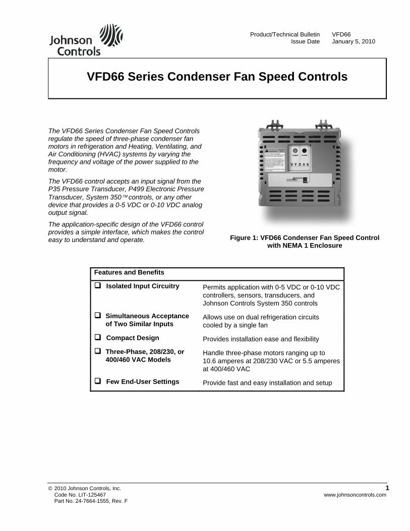
VFD66 Series Condenser Fan Speed Controls
The VFD66 Series Condenser Fan Speed Controls regulate the speed of three-phase condenser fan motors in refrigeration and Heating, Ventilating, and Air Conditioning (HVAC) systems by varying the frequency and voltage of the power supplied to the motor.
The VFD66 control accepts an input signal from the P35 Pressure Transducer, P499 Electronic Pressure Transducer, System 350™ controls, or any other device that provides a 0-5 VDC or 0-10 VDC analog output signal.
The application-specific design of the VFD66 control provides a simple interface, which makes the control easy to understand and operate.
Figure 1: VFD66 Condenser Fan Speed Control with NEMA 1 Enclosure
Features and Benefits
Isolated Input Circuitry Permits application with 0-5 VDC or 0-10 VDC controllers, sensors, transducers, and Johnson Controls System 350 controls
Simultaneous Acceptance of Two Similar Inputs
Allows use on dual refrigeration circuits cooled by a single fan
Compact Design Provides installation ease and flexibility
Three-Phase, 208/230, or 400/460 VAC Models
Handle three-phase motors ranging up to 10.6 amperes at 208/230 VAC or 5.5 amperes at 400/460 VAC
Few End-User Settings Provide fast and easy installation and setup
Code No. LIT-125467 www.johnsoncontrols.com Part No. 24-7664-1555, Rev. F
Application IMPORTANT: The VFD66 Series Condenser Fan Speed Controls are intended to control equipment under normal operating conditions. Where failure or malfunction of a VFD66 control could lead to an abnormal operating condition that could cause personal injury or damage to the equipment or other property, other devices (limit or safety controls), or systems (alarm or supervisory) intended to warn of or protect against failure or malfunction of the VFD66 control must be incorporated into and maintained as part of the control system.
The VFD66 control accepts input signals from a variety of pressure transducers, temperature sensors, and low-voltage controllers to provide continuous response to changing condenser load conditions.
The VFD66 control allows the system to:
maintain optimum condenser head pressure in low ambient temperature conditions
eliminate short-cycling in low ambient temperatures or changing load conditions
match the condenser fan speed to the load on the condenser, which increases the efficiency of the refrigeration system. This can reduce electricity cost and help maintain a constant evaporator temperature.
Terminal Access Cover
TerminalCover Screw
Heat Sink
7-1/2(190)
7(177)
3 conduit openings
7/8-in. (22 mm) actual size1/2-in. trade size
1/4-in. (6 mm) mounting screws,
4 places
6-1/4(159)
4-3/4(120)
4-5/8(117)
7-1/4(184)
DiagnosticLight-Emitting Diodes (LEDs)
Figure 2: VFD66 NEMA 1 Enclosure Dimensions
The VFD66 control can also:
stabilize the condenser head pressures, which helps optimize compressor operation and can reduce wear and extend compressor life
eliminate the condenser fan short-cycling, which can reduce motor repair and replacement costs
stabilize evaporator temperatures, which can extend refrigerated product life and provide more consistent comfort cooling
Mounting
! CAUTION: Risk of Property Damage. The VFD66 control can generate and dissipate significant heat. Mount the control on a metal, concrete, or cinderblock mounting surface. Mounting the VFD66 control on surfaces made of wood or other heat-sensitive material may result in damage to the mounting surface.
Observe the following the guidelines when mounting a VFD66 control:
Mount the VFD66 control on a vertical surface with the heat sink fins oriented vertically and the conduit holes facing down.
Provide a minimum of 4 in. (102 mm) clearance around the heat sink.
Ensure that output power wiring between the VFD66 control and the motor does not exceed 50 ft (15 m).
Mount the VFD66 control indoors, in a location protected from explosive vapors, corrosive gas, water, and dust.
Ambient air temperature and installation altitude affect the maximum output rating of the VFD66 controls (see De-Rating the VFD66 Control for High Temperatures and High Altitudes).
2 VFD66 Series Condenser Fan Speed Controls Product/Technical Bulletin
Wiring Read this entire section, including the information on emissions compliance, before wiring the VFD66 control. Follow these guidelines when wiring the VFD66 control: ! WARNING: Risk of Electric Shock.
Disconnect the power supply before making electrical connections. The printed circuit board and its components are at AC line voltage. Contact with components carrying hazardous voltage can cause electric shock and may result in personal injury or death.
• Use copper conductors only.
• Size field wiring based on 75°C.
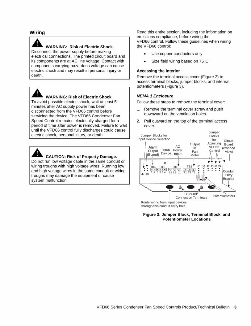
Accessing the Interior Remove the terminal access cover (Figure 2) to access terminal blocks, jumper blocks, and internal potentiometers (Figure 3).
! WARNING: Risk of Electric Shock. To avoid possible electric shock, wait at least 5 minutes after AC supply power has been disconnected from the VFD66 control before servicing the device. The VFD66 Condenser Fan Speed Control remains electrically charged for a period of time after power is removed. Failure to wait until the VFD66 control fully discharges could cause electric shock, personal injury, or death.
NEMA 1 Enclosure Follow these steps to remove the terminal cover:
1. Remove the terminal cover screw and push downward on the ventilation holes.
2. Pull outward on the top of the terminal access cover.
J7 J8
TB3
1 2 3 4
TB1
L3 L2 L1
TB2
P1
T1 T2 T3
J5 J6 J2 J3 J4 J9
Circuit Board
(cropped view)
ConduitEntry
Bracket
Potentiometers
P2
Jumper Blocks
for AdjustingVFD66 Control
Jumper Blocks for Input Device Selection
Ground Connection Terminals
Route wiring from input devices through this conduit entry hole.
InputDevice
AC PowerInput
Outputto
Fan Motor
! CAUTION: Risk of Property Damage. Do not run low voltage cable in the same conduit or wiring troughs with high voltage wires. Running low and high voltage wires in the same conduit or wiring troughs may damage the equipment or cause system malfunction.
Figure 3: Jumper Block, Terminal Block, and Potentiometer Locations
VFD66 Series Condenser Fan Speed Controls Product/Technical Bulletin 3
Table 1: Terminal Blocks
Terminal Block Label
Terminal Block Function Electrical Rating Terminal Terminal Function
L1 Line 1 Input L2 Line 2 Input
TB1 Input Line-Voltage Supply Power
L3 Line 3 Input T1 Line 1 Output T2 Line 2 Output
TB2 Output Line-Voltage Power to Fan Motor
See Technical Specifications.
T3 Line 3 Output 1 5 VDC power supply 2 First signal input 3 Second signal input1
TB3 Low-voltage Input Signals, 0-5 VDC Power Supply
0-5 VDC or 0-10 VDC
4 Common 1 Switch contact TB4 Alarm Output for User-Installed
Alarm Device 100 mA at 24 VAC/30 VDC
2 Switch contact 1. See Adjusting the Control Settings.
Wiring Input Devices to a VFD66 Connect the appropriate low-voltage input signal device to Terminal Block TB3 (Figure 3). See Table 2, Figure 4, Figure 5, and Figure 6 for additional information on wiring specific Johnson Controls/PENN™ input devices to the VFD66 controls.
Table 2: Wiring Johnson Controls/PENN Input Devices Input Device Input Device
Terminal VFD66 Control TB3 Terminal
1 1 2 2 (or 3)1
P35AG-9200R Transducer
3 4 V 2 (or 3)1 A350PS-1C or
P352PN Series Controls
C 4
Red 1 White 2 (or 3)1
P499 Series Transducers
Black 4 1. Use Terminal 3 to connect an optional second
input device to the VFD66 (Figure 5).
TB3
2
2
1 3
3 4
P35 Transducer
1
Figure 4: Wiring P35 Transducers to VFD66 Terminal Block 3
White(Second Output Signal)
Red (5 VDC Supply)
White (Output Signal)P499 Transducer
TB3
Black (Common)
Second P499 Transducer(Optional)
Red (5 VDC Supply)
Black (Common)
1 2 3 4
Figure 5: Wiring P499 Transducers to VFD66 Terminal Block 3 (TB3)
4 VFD66 Series Condenser Fan Speed Controls Product/Technical Bulletin
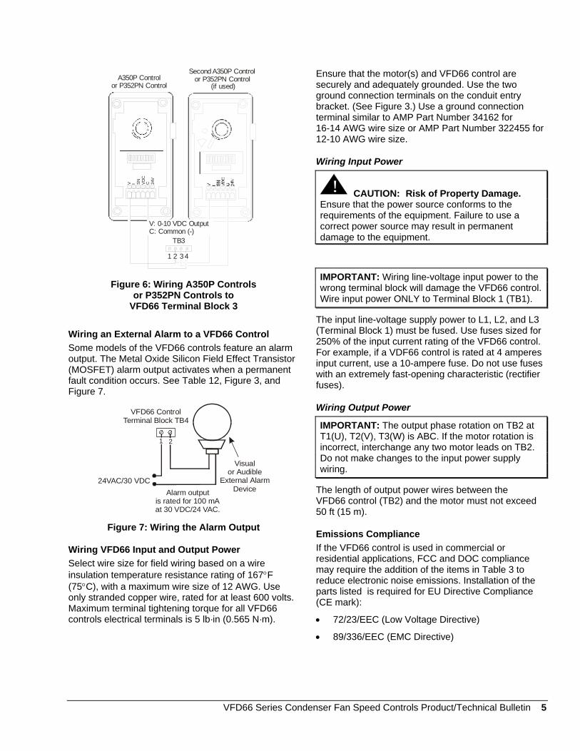
TB3
1
V I SN
VD
CC 24
V
A350P Control or P352PN Control
Second A350P Control or P352PN Control
(if used)
2 4
C: Common (-)V: 0-10 VDC Output
3
Figure 6: Wiring A350P Controls or P352PN Controls to
VFD66 Terminal Block 3
Wiring an External Alarm to a VFD66 Control Some models of the VFD66 controls feature an alarm output. The Metal Oxide Silicon Field Effect Transistor (MOSFET) alarm output activates when a permanent fault condition occurs. See Table 12, Figure 3, and Figure 7.
Visual or Audible
External Alarm DeviceAlarm output
is rated for 100 mA at 30 VDC/24 VAC.
21
24VAC/30 VDC
VFD66 ControlTerminal Block T 4B
Figure 7: Wiring the Alarm Output
Wiring VFD66 Input and Output Power Select wire size for field wiring based on a wire insulation temperature resistance rating of 167°F (75°C), with a maximum wire size of 12 AWG. Use only stranded copper wire, rated for at least 600 volts. Maximum terminal tightening torque for all VFD66 controls electrical terminals is 5 lb·in (0.565 N·m).
Ensure that the motor(s) and VFD66 control are securely and adequately grounded. Use the two ground connection terminals on the conduit entry bracket. (See Figure 3.) Use a ground connection terminal similar to AMP Part Number 34162 for 16-14 AWG wire size or AMP Part Number 322455 for 12-10 AWG wire size.
Wiring Input Power
! CAUTION: Risk of Property Damage. Ensure that the power source conforms to the requirements of the equipment. Failure to use a correct power source may result in permanent damage to the equipment.
IMPORTANT: Wiring line-voltage input power to the wrong terminal block will damage the VFD66 control. Wire input power ONLY to Terminal Block 1 (TB1).
The input line-voltage supply power to L1, L2, and L3 (Terminal Block 1) must be fused. Use fuses sized for 250% of the input current rating of the VFD66 control. For example, if a VDF66 control is rated at 4 amperes input current, use a 10-ampere fuse. Do not use fuses with an extremely fast-opening characteristic (rectifier fuses).
Wiring Output Power
IMPORTANT: The output phase rotation on TB2 at T1(U), T2(V), T3(W) is ABC. If the motor rotation is incorrect, interchange any two motor leads on TB2. Do not make changes to the input power supply wiring.
The length of output power wires between the VFD66 control (TB2) and the motor must not exceed 50 ft (15 m).
Emissions Compliance If the VFD66 control is used in commercial or residential applications, FCC and DOC compliance may require the addition of the items in Table 3 to reduce electronic noise emissions. Installation of the parts listed is required for EU Directive Compliance (CE mark):
• 72/23/EEC (Low Voltage Directive)
• 89/336/EEC (EMC Directive)
VFD66 Series Condenser Fan Speed Controls Product/Technical Bulletin 5
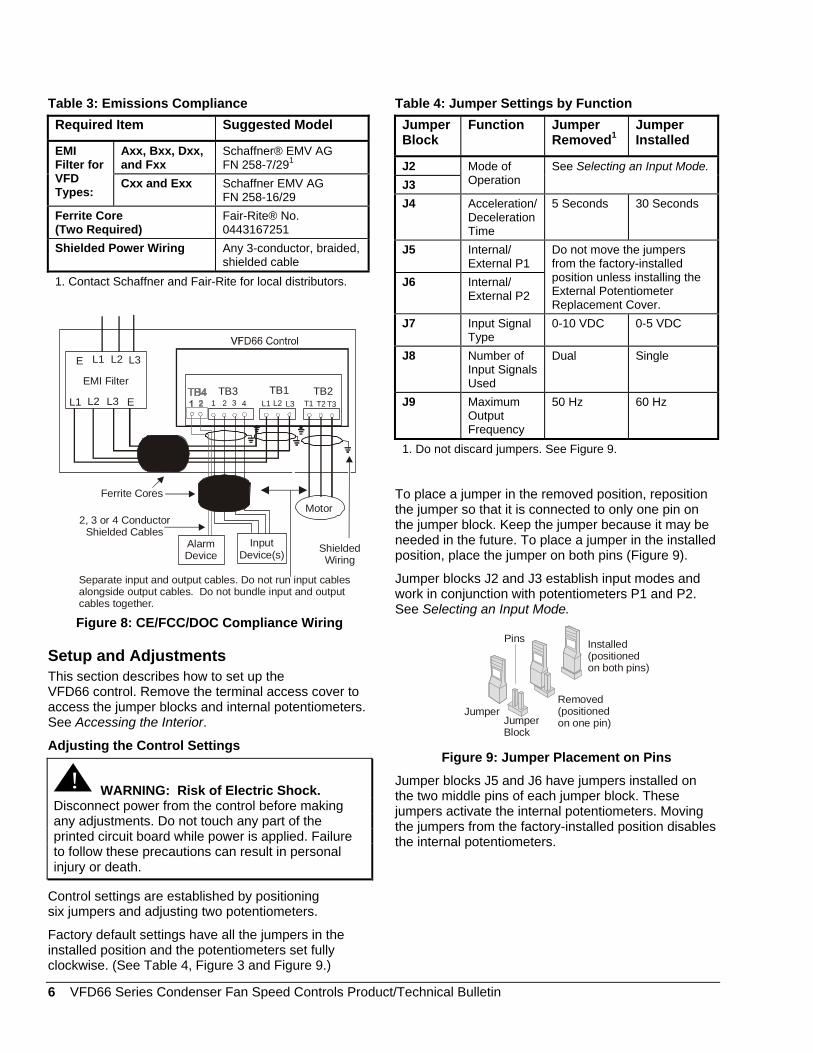
Table 3: Emissions Compliance Required Item Suggested Model
Axx, Bxx, Dxx, and Fxx
Schaffner® EMV AG FN 258-7/291
EMI Filter for VFD Types:
Cxx and Exx Schaffner EMV AG FN 258-16/29
Ferrite Core (Two Required)
Fair-Rite® No. 0443167251
Shielded Power Wiring Any 3-conductor, braided, shielded cable
1. Contact Schaffner and Fair-Rite for local distributors.
TB3 TB1 TB21 2 3 4 L1 L2 L3 T1 T2 T3L1
L1
L2
L2
L3
L3
E
Motor
EMI Filter
E
ShieldedWiring
Separate input and output cables. Do not run input cables alongside output cables. Do not bundle input and output cables together.
InputDevice(s)
Ferrite Cores
2, 3 or 4 Conductor Shielded Cables
AlarmDevice
Figure 8: CE/FCC/DOC Compliance Wiring
Setup and Adjustments This section describes how to set up the VFD66 control. Remove the terminal access cover to access the jumper blocks and internal potentiometers. See Accessing the Interior.
Adjusting the Control Settings
! WARNING: Risk of Electric Shock. Disconnect power from the control before making any adjustments. Do not touch any part of the printed circuit board while power is applied. Failure to follow these precautions can result in personal injury or death.
Control settings are established by positioning six jumpers and adjusting two potentiometers.
Factory default settings have all the jumpers in the installed position and the potentiometers set fully clockwise. (See Table 4, Figure 3 and Figure 9.)
Table 4: Jumper Settings by Function Jumper Block
Function Jumper Removed1
Jumper Installed
J2 J3
Mode of Operation
See Selecting an Input Mode.
J4 Acceleration/Deceleration Time
5 Seconds 30 Seconds
J5 Internal/ External P1
J6 Internal/ External P2
Do not move the jumpers from the factory-installed position unless installing the External Potentiometer Replacement Cover.
J7 Input Signal Type
0-10 VDC 0-5 VDC
J8 Number of Input Signals Used
Dual Single
J9 Maximum Output Frequency
50 Hz 60 Hz
1. Do not discard jumpers. See Figure 9.
To place a jumper in the removed position, reposition the jumper so that it is connected to only one pin on the jumper block. Keep the jumper because it may be needed in the future. To place a jumper in the installed position, place the jumper on both pins (Figure 9).
Jumper blocks J2 and J3 establish input modes and work in conjunction with potentiometers P1 and P2. See Selecting an Input Mode.
Jumper
Pins
Removed(positionedon one pin)
Installed(positionedon both pins)
JumperBlock
Figure 9: Jumper Placement on Pins
Jumper blocks J5 and J6 have jumpers installed on the two middle pins of each jumper block. These jumpers activate the internal potentiometers. Moving the jumpers from the factory-installed position disables the internal potentiometers.
6 VFD66 Series Condenser Fan Speed Controls Product/Technical Bulletin
Jumpers on J7 and J8 must be set for the correct input voltage range and number of input devices. (See Table 4.) Jumper block J7 sets the voltage range for the input signal(s). If the jumper on jumper block J7 is incorrectly set, the control may operate in an unexpected manner. See Troubleshooting.
Jumper block J8 selects the number of input signals used. When dual inputs are selected, Terminal 3 of TB3 (TB3-3) is enabled. The VFD66 control varies the speed of the fan motor in accordance with the higher value of the two input signals received. If the jumper on jumper block J8 is incorrectly set, the control may operate in an unexpected manner. See Troubleshooting.
Jumper block J9 selects maximum frequency output of the control. Remove the jumper for 50 Hz motors, typically used in Europe. Install the jumper for 60 Hz motors, typically used in North America. Power to the VFD66 control must be disconnected and reconnected before frequency changes take effect.
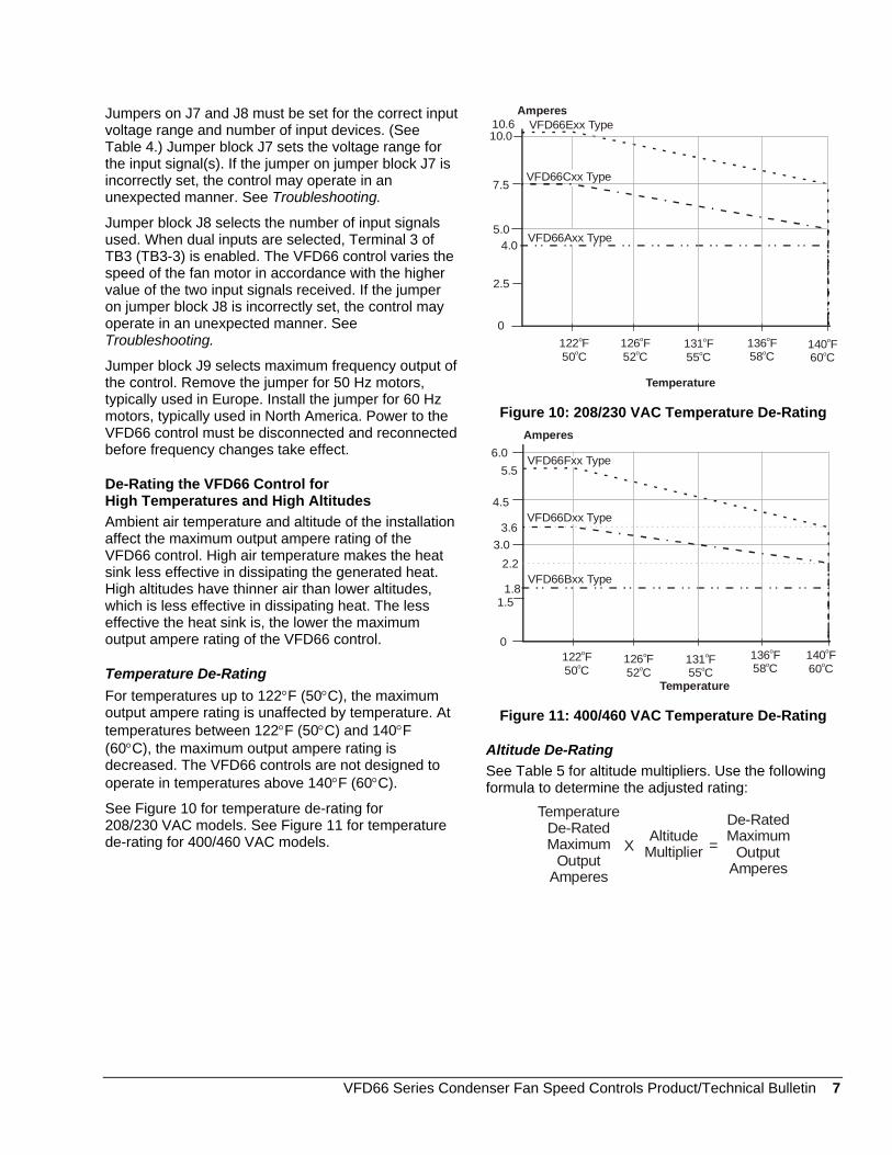
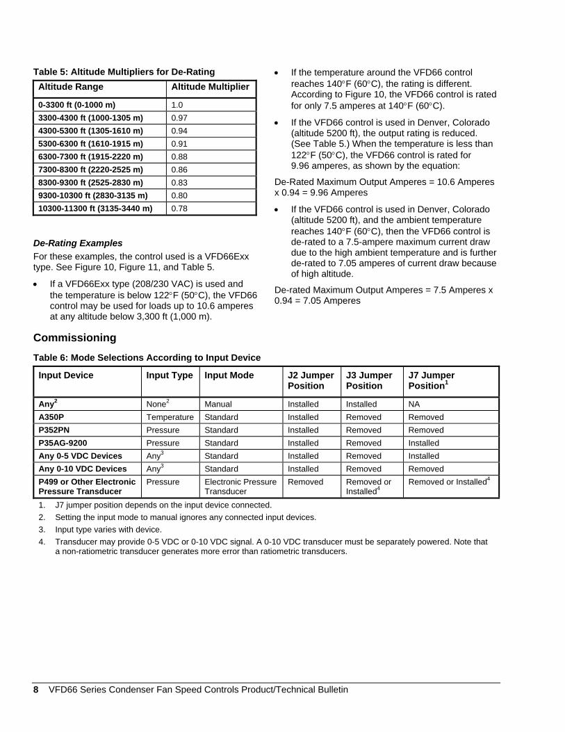
De-Rating the VFD66 Control for High Temperatures and High Altitudes Ambient air temperature and altitude of the installation affect the maximum output ampere rating of the VFD66 control. High air temperature makes the heat sink less effective in dissipating the generated heat. High altitudes have thinner air than lower altitudes, which is less effective in dissipating heat. The less effective the heat sink is, the lower the maximum output ampere rating of the VFD66 control.
Temperature De-Rating For temperatures up to 122°F (50°C), the maximum output ampere rating is unaffected by temperature. At temperatures between 122°F (50°C) and 140°F (60°C), the maximum output ampere rating is decreased. The VFD66 controls are not designed to operate in temperatures above 140°F (60°C).
See Figure 10 for temperature de-rating for 208/230 VAC models. See Figure 11 for temperature de-rating for 400/460 VAC models.
Amperes
Temperature
10.0
0
5.0
7.5
2.5
122 F50 C
o
o140 F60 C
o
o131 F55 C
o
o126 F52 C
o
o136 F58 C
o
o
4.0
10.6
VFD66Axx Type
VFD66Cxx Type
VFD66Exx Type
Figure 10: 208/230 VAC Temperature De-Rating Amperes
Temperature
6.0
0
3.0
4.5
1.5
122 F50 C
o
o140 F60 C
o
o
5.5
1.8
3.6
2.2
131 F55 C
o
o126 F52 C
o
o
136 F58 C
o
o
VFD66Fxx Type
VFD66Dxx Type
VFD66Bxx Type
Figure 11: 400/460 VAC Temperature De-Rating
Altitude De-Rating See Table 5 for altitude multipliers. Use the following formula to determine the adjusted rating:
TemperatureDe-Rated Maximum
OutputAmperes
XAltitude
Multiplier =
De-RatedMaximum
OutputAmperes
VFD66 Series Condenser Fan Speed Controls Product/Technical Bulletin 7
8 VFD66 Series Condenser Fan Speed Controls Product/Technical Bulletin
Table 5: Altitude Multipliers for De-Rating Altitude Range Altitude Multiplier
0-3300 ft (0-1000 m) 1.0 3300-4300 ft (1000-1305 m) 0.97 4300-5300 ft (1305-1610 m) 0.94 5300-6300 ft (1610-1915 m) 0.91 6300-7300 ft (1915-2220 m) 0.88 7300-8300 ft (2220-2525 m) 0.86 8300-9300 ft (2525-2830 m) 0.83 9300-10300 ft (2830-3135 m) 0.80 10300-11300 ft (3135-3440 m) 0.78
De-Rating Examples For these examples, the control used is a VFD66Exx type. See Figure 10, Figure 11, and Table 5.
• If a VFD66Exx type (208/230 VAC) is used and the temperature is below 122°F (50°C), the VFD66 control may be used for loads up to 10.6 amperes at any altitude below 3,300 ft (1,000 m).
• If the temperature around the VFD66 control reaches 140°F (60°C), the rating is different. According to Figure 10, the VFD66 control is rated for only 7.5 amperes at 140°F (60°C).
• If the VFD66 control is used in Denver, Colorado (altitude 5200 ft), the output rating is reduced. (See Table 5.) When the temperature is less than 122°F (50°C), the VFD66 control is rated for 9.96 amperes, as shown by the equation:
De-Rated Maximum Output Amperes = 10.6 Amperes x 0.94 = 9.96 Amperes
• If the VFD66 control is used in Denver, Colorado (altitude 5200 ft), and the ambient temperature reaches 140°F (60°C), then the VFD66 control is de-rated to a 7.5-ampere maximum current draw due to the high ambient temperature and is further de-rated to 7.05 amperes of current draw because of high altitude.
De-rated Maximum Output Amperes = 7.5 Amperes x 0.94 = 7.05 Amperes
Commissioning
Table 6: Mode Selections According to Input Device
Input Device Input Type Input Mode J2 Jumper Position
J3 Jumper Position
J7 Jumper Position1
Any2 None2 Manual Installed Installed NA A350P Temperature Standard Installed Removed Removed P352PN Pressure Standard Installed Removed Removed P35AG-9200 Pressure Standard Installed Removed Installed Any 0-5 VDC Devices Any3 Standard Installed Removed Installed Any 0-10 VDC Devices Any3 Standard Installed Removed Removed P499 or Other Electronic Pressure Transducer
Pressure Electronic Pressure Transducer
Removed Removed or Installed4
Removed or Installed4
1. J7 jumper position depends on the input device connected. 2. Setting the input mode to manual ignores any connected input devices. 3. Input type varies with device. 4. Transducer may provide 0-5 VDC or 0-10 VDC signal. A 0-10 VDC transducer must be separately powered. Note that
a non-ratiometric transducer generates more error than ratiometric transducers.
Selecting an Input Mode See Table 6 for the available input mode options for the VFD66 control. The factory–set mode is Manual Input mode. Manual Input Mode Manual Input mode allows the user to set a constant motor speed. This can be used where manual control is desired or while repairing input signal devices or obtaining replacements. In Manual Input mode, the input device signals are disregarded. Motor speed is controlled by adjusting the P1 potentiometer. Potentiometer P2 is disregarded and adjusting P2 has no effect.
Table 7: Manual Input Mode J2 Jumper Position
J3 Jumper Position
P1: Motor Speed
P2: Not Used
Installed Installed Adjusts constant speed of motor (0-100%)
—
Standard Input Mode Standard Input mode is the most commonly used mode. The majority of input devices compatible with the VFD66 controls are used with this mode. The input device determines the setpoint and proportional band.
Table 8: Standard Input Mode J2 Jumper Position
J3 Jumper Position
P1: Minimum Motor Speed
P2: Motor Action at Minimum Speed
CCW: Motor idles.
Installed Removed Can be set at 0-50% of maximum motor speed.
CW: Motor shuts off.
P1 adjusts the minimum speed of the motor. The minimum speed is adjustable from 0 to 50% of total motor speed. Turning P1 Clockwise (CW) increases minimum speed setting, Counterclockwise (CCW) decreases minimum speed setting. P2 determines whether the motor idles at minimum speed or shuts off at minimum speed. P2 must be set at full CCW or full CW position; intermediate settings have no effect.
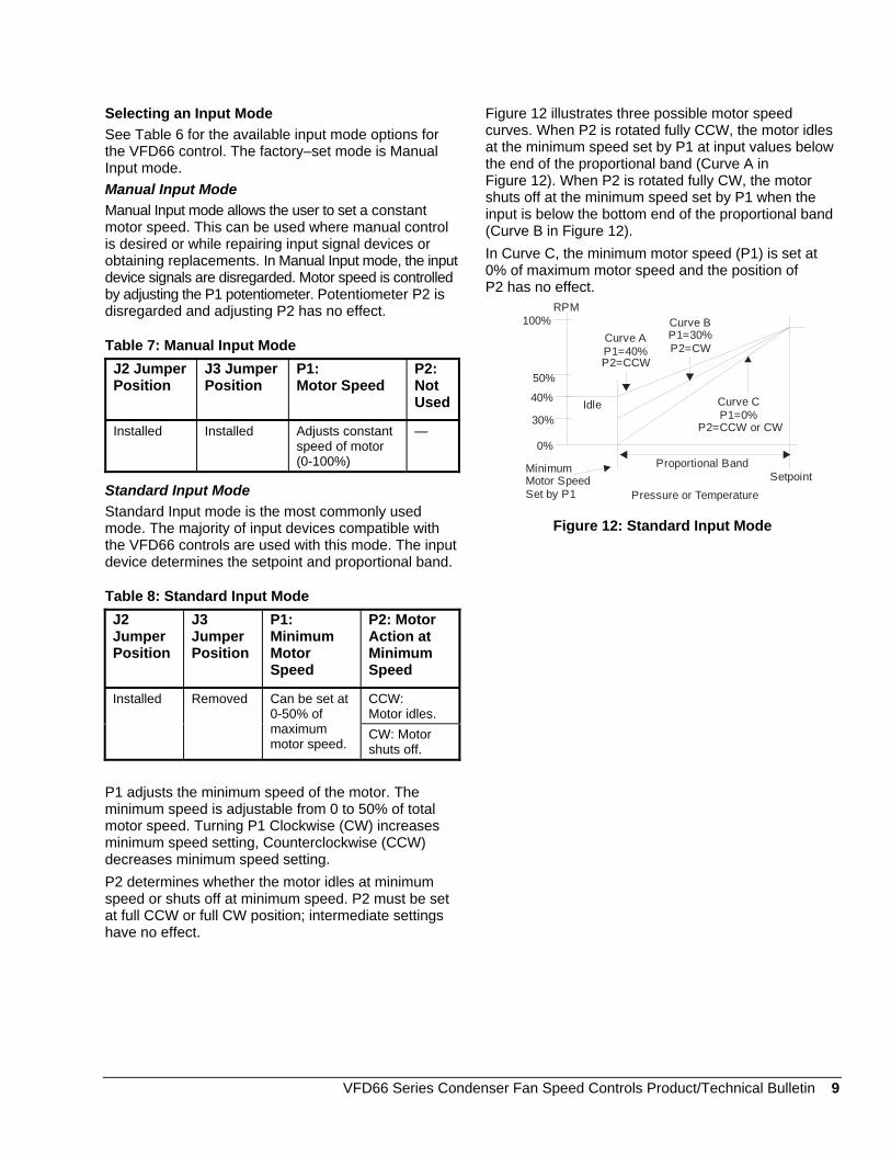
Figure 12 illustrates three possible motor speed curves. When P2 is rotated fully CCW, the motor idles at the minimum speed set by P1 at input values below the end of the proportional band (Curve A in Figure 12). When P2 is rotated fully CW, the motor shuts off at the minimum speed set by P1 when the input is below the bottom end of the proportional band (Curve B in Figure 12). In Curve C, the minimum motor speed (P1) is set at 0% of maximum motor speed and the position of P2 has no effect.
Pressure or Temperature
RPM100%
50%
SetpointProportional Band
40%
30%
MinimumMotor SpeedSet by P1
Idle
Curve B
P2=CW P1=30%
Curve C
P2=CCW or CWP1=0%
Curve A
P2=CCWP1=40%
0%
Figure 12: Standard Input Mode
VFD66 Series Condenser Fan Speed Controls Product/Technical Bulletin 9
P2 adjusts the proportional band over which fan motor speed is controlled.
Electronic Pressure Transducer Input Mode
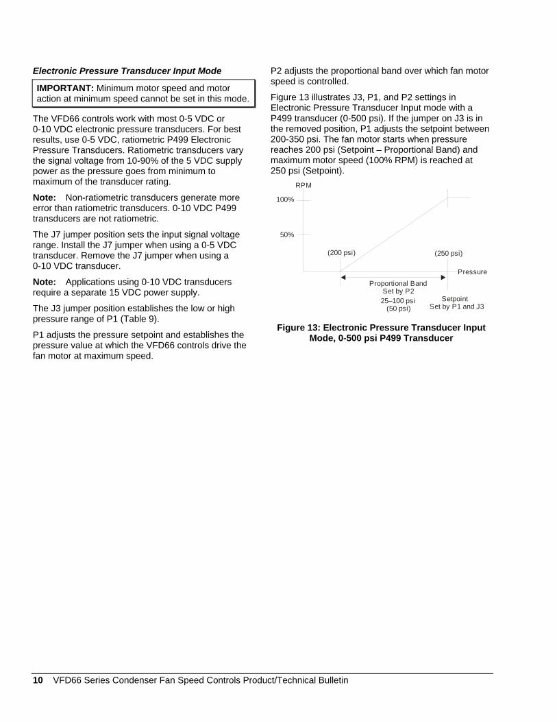
IMPORTANT: Minimum motor speed and motor action at minimum speed cannot be set in this mode. Figure 13 illustrates J3, P1, and P2 settings in
Electronic Pressure Transducer Input mode with a P499 transducer (0-500 psi). If the jumper on J3 is in the removed position, P1 adjusts the setpoint between 200-350 psi. The fan motor starts when pressure reaches 200 psi (Setpoint – Proportional Band) and maximum motor speed (100% RPM) is reached at 250 psi (Setpoint).
The VFD66 controls work with most 0-5 VDC or 0-10 VDC electronic pressure transducers. For best results, use 0-5 VDC, ratiometric P499 Electronic Pressure Transducers. Ratiometric transducers vary the signal voltage from 10-90% of the 5 VDC supply power as the pressure goes from minimum to maximum of the transducer rating.
Pressure
RPM
100%
50%
SetpointSet by P1 and J3
25–100 psi(50 psi)
Proportional BandSet by P2
(200 psi) (250 psi)
Note: Non-ratiometric transducers generate more error than ratiometric transducers. 0-10 VDC P499 transducers are not ratiometric.
The J7 jumper position sets the input signal voltage range. Install the J7 jumper when using a 0-5 VDC transducer. Remove the J7 jumper when using a 0-10 VDC transducer.
Note: Applications using 0-10 VDC transducers require a separate 15 VDC power supply.
The J3 jumper position establishes the low or high pressure range of P1 (Table 9).
Figure 13: Electronic Pressure Transducer Input Mode, 0-500 psi P499 Transducer P1 adjusts the pressure setpoint and establishes the
pressure value at which the VFD66 controls drive the fan motor at maximum speed.
10 VFD66 Series Condenser Fan Speed Controls Product/Technical Bulletin
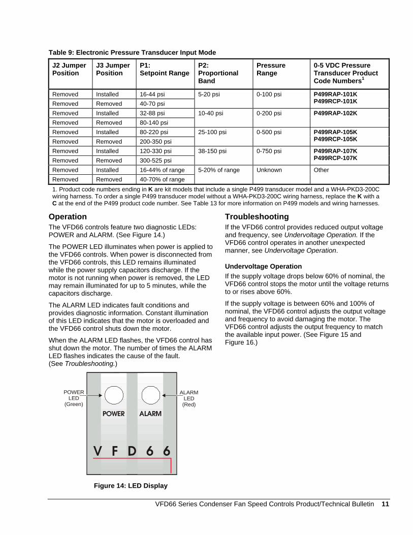
Table 9: Electronic Pressure Transducer Input Mode
J2 Jumper Position
J3 Jumper Position
P1: Setpoint Range
P2: Proportional Band
Pressure Range
0-5 VDC Pressure Transducer Product Code Numbers1
Removed Installed 16-44 psi Removed Removed 40-70 psi
5-20 psi 0-100 psi P499RAP-101K P499RCP-101K
Removed Installed 32-88 psi Removed Removed 80-140 psi
10-40 psi 0-200 psi P499RAP-102K
Removed Installed 80-220 psi Removed Removed 200-350 psi
25-100 psi 0-500 psi P499RAP-105K P499RCP-105K
Removed Installed 120-330 psi Removed Removed 300-525 psi
38-150 psi 0-750 psi P499RAP-107K P499RCP-107K
Removed Installed 16-44% of range Removed Removed 40-70% of range
5-20% of range Unknown Other
1. Product code numbers ending in K are kit models that include a single P499 transducer model and a WHA-PKD3-200C wiring harness. To order a single P499 transducer model without a WHA-PKD3-200C wiring harness, replace the K with a C at the end of the P499 product code number. See Table 13 for more information on P499 models and wiring harnesses.
Operation The VFD66 controls feature two diagnostic LEDs: POWER and ALARM. (See Figure 14.)
The POWER LED illuminates when power is applied to the VFD66 controls. When power is disconnected from the VFD66 controls, this LED remains illuminated while the power supply capacitors discharge. If the motor is not running when power is removed, the LED may remain illuminated for up to 5 minutes, while the capacitors discharge.
The ALARM LED indicates fault conditions and provides diagnostic information. Constant illumination of this LED indicates that the motor is overloaded and the VFD66 control shuts down the motor.
When the ALARM LED flashes, the VFD66 control has shut down the motor. The number of times the ALARM LED flashes indicates the cause of the fault. (See Troubleshooting.)
POWER LED
(Green)
ALARMLED(Red)
Figure 14: LED Display
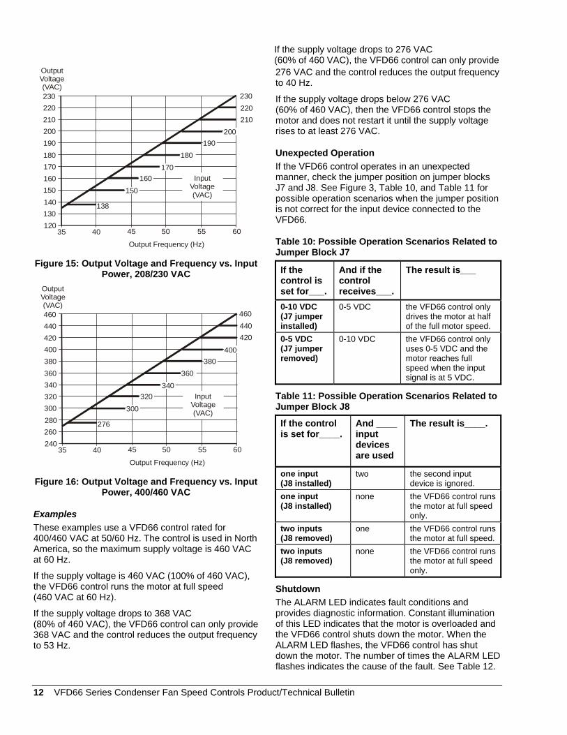
Troubleshooting If the VFD66 control provides reduced output voltage and frequency, see Undervoltage Operation. If the VFD66 control operates in another unexpected manner, see Undervoltage Operation.
Undervoltage Operation If the supply voltage drops below 60% of nominal, the VFD66 control stops the motor until the voltage returns to or rises above 60%.
If the supply voltage is between 60% and 100% of nominal, the VFD66 control adjusts the output voltage and frequency to avoid damaging the motor. The VFD66 control adjusts the output frequency to match the available input power. (See Figure 15 and Figure 16.)
VFD66 Series Condenser Fan Speed Controls Product/Technical Bulletin 11
230220210200190180170160150140130120
35 40 45 50 55 60
Output Frequency (Hz)
OutputVoltage (VAC)
220 210
200 190
180
170160
150
138
InputVoltage(VAC)
230
Figure 15: Output Voltage and Frequency vs. Input Power, 208/230 VAC
460440420400380360340320300280260240
35 40 45 50 55 60
Output Frequency (Hz)
OutputVoltage (VAC)
440 420
400 380
360
340320
300
276
InputVoltage(VAC)
460
Figure 16: Output Voltage and Frequency vs. Input Power, 400/460 VAC
Examples These examples use a VFD66 control rated for 400/460 VAC at 50/60 Hz. The control is used in North America, so the maximum supply voltage is 460 VAC at 60 Hz.
If the supply voltage is 460 VAC (100% of 460 VAC), the VFD66 control runs the motor at full speed (460 VAC at 60 Hz).
If the supply voltage drops to 368 VAC (80% of 460 VAC), the VFD66 control can only provide 368 VAC and the control reduces the output frequency to 53 Hz.
If the supply voltage drops to 276 VAC (60% of 460 VAC), the VFD66 control can only provide
276 VAC and the control reduces the output frequency to 40 Hz.
If the supply voltage drops below 276 VAC (60% of 460 VAC), then the VFD66 control stops the motor and does not restart it until the supply voltage rises to at least 276 VAC.
Unexpected Operation If the VFD66 control operates in an unexpected manner, check the jumper position on jumper blocks J7 and J8. See Figure 3, Table 10, and Table 11 for possible operation scenarios when the jumper position is not correct for the input device connected to the VFD66.
Table 10: Possible Operation Scenarios Related to Jumper Block J7
If the control is set for___.
And if the control receives___.
The result is___
0-10 VDC (J7 jumper installed)
0-5 VDC the VFD66 control only drives the motor at half of the full motor speed.
0-5 VDC (J7 jumper removed)
0-10 VDC the VFD66 control only uses 0-5 VDC and the motor reaches full speed when the input signal is at 5 VDC.
Table 11: Possible Operation Scenarios Related to Jumper Block J8
If the control is set for____.
And ____ input devices are used
The result is____.
one input (J8 installed)
two the second input device is ignored.
one input (J8 installed)
none the VFD66 control runs the motor at full speed only.
two inputs (J8 removed)
one the VFD66 control runs the motor at full speed.
two inputs (J8 removed)
none the VFD66 control runs the motor at full speed only.
Shutdown The ALARM LED indicates fault conditions and provides diagnostic information. Constant illumination of this LED indicates that the motor is overloaded and the VFD66 control shuts down the motor. When the ALARM LED flashes, the VFD66 control has shut down the motor. The number of times the ALARM LED flashes indicates the cause of the fault. See Table 12.
12 VFD66 Series Condenser Fan Speed Controls Product/Technical Bulletin
If the supply voltage drops to 276 VAC (60% of 460 VAC), the VFD66 control can only provide
276 VAC and the control reduces the output frequency to 40 Hz.
VFD66 Series Condenser Fan Speed Controls Product/Technical Bulletin 13
After shutdown, there is a 30-second time delay before the VFD66 control initiates an automatic restart. The result is one of the following:
If the fault condition is corrected, the VFD66 control continues to operate. After 500 seconds, the fault routine resets automatically.
If the fault persists, the VFD66 controls lock out again, requiring reset.
Resetting a Locked-Out VFD66 Control
To reset a locked-out VFD66 control, follow the procedure below:
1. Disconnect power from the VFD66 control.
2. Wait 5 minutes to allow the internal capacitors to fully discharge.
3. Reapply power to the VFD66 control.
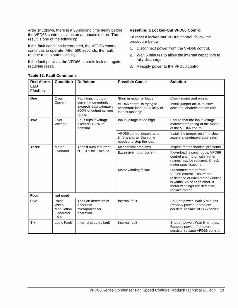
Table 12: Fault Conditions Red Alarm LED Flashes
Condition Definition Possible Cause Solution
Short in motor or leads Check motor and wiring. One Over Current
Fault trips if output current momentarily exceeds approximately 200% of output current rating.
VFD66 control is trying to accelerate load too quickly or load is too large.
Install jumper on J4 to slow acceleration/deceleration rate.
Input voltage is too high. Ensure that the input voltage matches the rating of the model of the VFD66 control.
Two Over Voltage
Fault trips if voltage exceeds 123% of nominal.
VFD66 control deceleration time is shorter than time needed to stop the load.
Install the jumper on J4 to slow acceleration/deceleration rate.
Mechanical problems Inspect for mechanical problems. Excessive motor current If overload is continuous, VFD66
control and motor with higher ratings may be required. Check motor specifications.
Three Motor Overload
Trips if output current is 110% for 1 minute.
Motor winding failure Disconnect motor from VFD66 control. Ensure that resistance of each motor winding is within 5% of each other. If motor windings are defective, replace motor.
Four not used Five Pulse
Width Modulation Generator Fault
Trips on detection of abnormal microprocessor operation.
Internal fault Shut off power. Wait 5 minutes. Reapply power. If problem persists, replace VFD66 control.
Six Logic Fault Internal circuitry fault Internal fault Shut off power. Wait 5 minutes. Reapply power. If problem persists, replace VFD66 control.
Selecting a Motor IMPORTANT: Do not exceed the VFD66 control’s maximum output ampere rating. Exceeding the control’s maximum output ampere rating can cause the VFD66 control to shut down on an overload fault.
The VFD66 control allows the motor to develop torque that varies with the current. The motor provides maximum torque at its maximum current draw. Use these guidelines to select the proper motor for use with the VFD66 control.
! CAUTION: Risk of Property Damage.
Use only three phase motors approved by the manufacturer for speed control applications with the VFD66 Control. Failure to use a three phase motor may damage the motor and other property.
Required Motor Specifications Motors used with the VFD66 Series Controls must:
have variable torque operation
be UL Recognized and CSA Certified, or equivalent
be AC induction 3-phase motors
be rated for 208/230 VAC, 60 Hz (230 VAC, 50 Hz) or 460 VAC, 60 Hz (400 VAC, 50 Hz)
have ball bearings
have an Inverter Rating (400/460 VAC motors)
have Insulation Class F or better
On 400/460 VAC models, the motor insulation system must be deemed suitable by the motor manufacturer for use on PWM (Pulse Width Modulated) IGBT (Insulated Gate Bipolar Transistor) variable frequency drives. These are also referred to as inverter-rated motors.
The VFD66 controls are suitable for use with thermally protected motors or the like intended by their manufacturer for fan speed modulating applications.
Multiple Motors A VFD66 control can control multiple motors; however, the sum of the Full Load Amperes (FLA) ratings for the motors must not exceed the maximum output amperage rating of the VFD66 control, including any de-rating due to altitude and/or temperature.
Ordering Information To select the proper model of the VFD66 control for a specific application:
1. Locate the nameplate (dataplate) on the motors intended for use with the VFD66 control. 400/460 VAC motors for use with the VFD66 controls must be inverter-rated motors. See Selecting a Motor for further information.
2. Identify the FLA ratings of each motor to be controlled by the VFD66 control. If more than one motor will be controlled, add the ratings of all the motors to determine the total FLA.
3. Adjust the VFD66 control’s current rating for temperature and altitude. See De-Rating the VFD66 Control for High Temperatures and High Altitudes.
4. Compare the sum of the amperage draw of the motors to the adjusted current rating of the VFD66 control. If the current required is between two VFD66 control models, select the model with the higher amperage rating.
5. Configure the product number of the desired VFD66 control by adding the appropriate 3-letter suffix to VFD66. See for product number configuration. See Table 15 for standard models. See Table 13 for input devices and other accessories.
For example, a VFD66BAA would be a VFD66 control rated at 1.8 amperes, 460 VAC at 60 Hz (B), NEMA 1 enclosure (A), Dual analog input signal (A).
Contact Johnson Controls/PENN application engineering at 1-800-275-5676 for more information.
14 VFD66 Series Condenser Fan Speed Controls Product/Technical Bulletin
Accessories Table 13 lists the recommended input devices and other accessories used with the VFD66 controls and available from Johnson Controls/PENN.
For applications that require 0-10 VDC pressure transducers, refer to the P499 Series Electronic Pressure Transducers Product/Technical Bulletin (LIT-12011190) for more information on available 0-10 VDC models.
Table 13: Pressure Transducers, Temperature Controls, and Other Accessories for VFD66 Series Controls Product Code Number
Description Accessory Information
P35AG-9200R Pressure Transducer 0-350 psi range
Refer to P35 Pressure Transducer and VFD66 Control Application Note (LIT-121418) for more information.
P499RAP-101K P499RCP-101K
One Electronic Pressure Transducer (0-100 psi range) and one WHA-PKD3-200C Wire Harness
P499RAP-102K One Electronic Pressure Transducer (0-200 psi range) and one WHA-PKD3-200C Wire Harness
P499RAP-105K P499RCP-105K
One Electronic Pressure Transducer (0-500 psi range) and WHA-PKD3-200C Wire Harness
P499RAP-107K P499RCP-107K
One Electronic Pressure Transducer, (0-750 psi range) and one WHA-PKD3-200C Wire Harness
WHA-PKD3-200C Wire Harness with pigtail leads, 6-1/2 ft (2 m)
WHA-PKD3-400C Wire Harness with pigtail leads, 13 ft (4 m)
WHA-PKD3-600C Wire Harness with pigtail leads, 19-5/8 ft (6 m)
Product code numbers ending in K are P499 kit models that include one P499 transducer model and one WHA-PKD3-200C (6-1/2 ft [2 m]) wiring harness. To order a single P499 transducer model (without a WHA-PKD3-200C wiring harness), replace the K with a C at the end of the P499 product code number. P499RAP type models are 0-5 VDC ratiometric pressure transducers with an 1/8 in. #27 NPT male/external thread (Style 49) fitting. P499RCP type models are 0-5 VDC ratiometric pressure transducers with a 1/4 in. SAE 45º Flare female/internal thread (7/16-20UNF) with valve depressor (Style 47) fitting. Refer to the P499 Series Electronic Pressure Transducers Product/Technical Bulletin (LIT-12011190) for more information on P499 pressure transducer models and the associated wire harnesses.
A350PS-1C Proportional Plus Integral Temperature Control
Refer to the System 350TM A350P Electronic Proportional Plus Integral Temperature Control Product/Technical Bulletin (LIT-930020) for more information.
A350PS-1C Proportional Plus Integral Pressure Control
Refer to the System 350TM P352PN Electronic Proportional Plus Integral Pressure Controls for PSI Applications Product/Technical Bulletin (LIT-930044) for more information.
VFD66-CVR-1C External Potentiometer Replacement Cover
Refer to the Installing the External Potentiometer Replacement Cover Application Note (LIT-121419) for more information.
VFD66 Series Condenser Fan Speed Controls Product/Technical Bulletin 15
Table 14: Ordering Information Matrix (Not all combinations are possible.) VFD66 Series
Condenser Fan Speed Controls
A 208/230 VAC, 60 Hz (230 VAC, 50 Hz), 4.0 amperes1 B 460 VAC, 60 Hz (400 VAC, 50 Hz), 1.8 amperes1 C 208/230 VAC, 60 Hz (230 VAC, 50 Hz), 7.5 amperes1 D 460 VAC, 60 Hz (400 VAC, 50 Hz), 3.6 amperes1 E 208/230 VAC, 60 Hz (230 VAC, 50 Hz), 10.6 amperes1 F 460 VAC, 60 Hz (400 VAC, 50 Hz), 5.5 amperes1
A NEMA 1 Enclosure B NEMA 1 Enclosure with Fan
E NEMA 4 Enclosure is not currently available.
A 0-5 VDC or 0-10 VDC Dual Analog Input Signal
E 0-5 VDC or 0-10 VDC Dual Analog Input Signal with Alarm Output
1. Maximum output ampere ratings. See De-Rating the VFD66 Control for High Temperatures and High Altitudes for temperature and altitude effects on VFD66 control ratings.
Table 15: Ordering Table for NEMA 1 Enclosure Models
Product Code Numbers Voltage Rating Ampere Rating1
Control Only Control with One P35 Transducer Included
Control Only with Alarm Output
4.0 VFD66AAA-1C VFD66AAA-100C VFD66AAE-1C 7.5 VFD66CAA-1C VFD66CAA-100C VFD66CAE-1C
208/230 VAC, 60 Hz (230 VAC, 50 Hz)
10.6 VFD66EBA-1C2 VFD66EBA-100C2 VFD66EBE-1C2 1.8 VFD66BAA-1C VFD66BAA-100C N/A 3.6 VFD66DAA-1C VFD66DAA-100C VFD66DAE-1C
460 VAC, 60 Hz (400 VAC, 50 Hz)
5.5 VFD66FBA-1C2 VFD66FBA-100C2 VFD66FBE-1C2
1. Maximum output ampere rating shown. See De-Rating the VFD66 Control for High Temperatures and High Altitudes for temperature and altitude effects on rating.
2. NEMA 1 Enclosure with Fan
Repairs and Replacement Field repairs of the VFD66 control should not be made. For a replacement VFD66 control or input devices, contact your local Johnson Controls/PENN distributor.
16 VFD66 Series Condenser Fan Speed Controls Product/Technical Bulletin
Technical Specifications Product VFD66 Series Condenser Fan Speed Controls
Input Power 208/230 VAC or 460 VAC @ 60 Hz (230 VAC or 400 VAC @ 50 Hz) Output Voltage/Frequency 208/230 VAC or 460 VAC @ 60 Hz (230 VAC or 400 VAC @ 50 Hz)
Pulse Width Modulation Carrier Frequency
2.3 kHz
Duty Continuous Overload Capacity 110% of ampere rating for 1 minute
Maximum Output Ampere Limit
110% of ampere rating, non-adjustable
Acceleration/Deceleration Selectable - 5 seconds or 30 seconds Start/Stop Line start with single auto-restart 30 seconds after fault
Lead Length Maximum lead length between motor and VFD66 control is 50 ft (15 m). Ambient Temperature Storage: -40 to 158°F (-40 to 70°C) Operating: -40 to 140°F (-40 to 60°C) – See De-Rating
the VFD66 Control for High Temperatures and High Altitudes.
Altitude 3,300 ft (1,000 m) maximum without de-rating maximum output amperes – See De-Rating the VFD66 Control for High Temperatures and High Altitudes.
Relative Humidity 0 to 95% noncondensing (storage and operating) Available Enclosures NEMA 1, UL Type 1 convection cooled (Some are fan cooled.)
Enclosures have three 1/2-in. trade size conduit openings. Agency Listings UL Listed, File E184521, Guides NMMS (UL 508C) and NMMS7 (CSA C22.2 No. 14).
Emissions Compliance FCC (US), DOC (Canada), based on EU testing with Emissions Compliance items installed, shown in Figure 8. EU Directive Compliance (CE mark); 72/23/EEC (Low Voltage Directive) and 89/336/EEC (EMC Directive) compliance with Emissions Compliance items installed, shown in Figure 8.
Input Devices Johnson Controls/PENN (A350P, P35, P352P, P499, Performer Rack Controllers) Johnson Controls Metasys® system (AHU, DME, DX9100, UNT, VAV) Also works with rack controllers, electronic pressure transducers, and other 0-5 VDC or 0-10 VDC input signal devices made by various manufacturers.
Dimensions (H x W x D) See Figure 2. Shipping Weight NEMA 1 Enclosure models – 5.6 lb (2.5 kg)
NEMA 1 Enlcosure models with Optional Alarm Board – 5.8 lb (2.6 kg)
The performance specifications are nominal and conform to acceptable industry standards. For application at conditions beyond these specifications, consult Johnson Controls/PENN Refrigeration Application Engineering at 1-800-275-5676. Johnson Controls, Inc. shall not be liable for damages resulting from misapplication or misuse of its products.
Building Efficiency 507 E. Michigan Street, Milwaukee, WI 53202
Metasys® and Johnson Controls® are registered trademarks of Johnson Controls, Inc. All other marks herein are the marks of their respective owners. © 2010 Johnson Controls, Inc.
VFD66 Series Condenser Fan Speed Controls Product/Technical Bulletin 17