Embed Size (px)
Citation preview
Created By: J. Pignatiello
4/19/2013
VFD Parameter Management
A thesis submitted to the Faculty of the Electrical & Computer Engineering Technology Program
of the University of Cincinnati
This document is a partial fulfillment of the requirements for the degree of
Bachelor of Science
in Electrical or Computer Engineering Technology at the College of Engineering & Applied Science
by
JAMES PIGNATIELLO
Bachelor of Science University of Cincinnati
May 2013
Faculty Advisor: Professor Haas
VFD Parameter Management Final Report Justin Best & James Pignatiello
College of Engineering & Applied Science Electrical Engineering Technology Senior Design
Submitted to: Professor Michael Haas
Professor James Everly
19 April, 2013

7970 Irwin Ave Cincinnati, OH 45236
19 April, 2013
Professor Michael Haas
University of Cincinnati
College of Engineering & Applied Science
2901 Woodside Dr
Cincinnati OH 45221
Dear Professor Haas:
The following is our final report for “Intellisense” which is being submitted at the request of the
ECET faculty.
This final report covers the details that led to the completion of our capstone project. This report
will cover the problem, solution, credibility, and methodology. These sections will be followed
by project conception, design objectives, methodology (design requirements, procedure, and
testing), budget, timeline, problems encountered, analysis of problems solved and future
recommendations. The collection of these sections will illustrate the process of how the device
was conceived as an idea, through its implementation.
Throughout the duration of this project a number of individuals contributed to the successful
completion of this project. These individuals in no particular order include: you, Mr. Rick
Uchtman, Mr. Patrick Saluke, Mr. Doug Charlton, Mr. Marc Thomas, Professor Xuefu Zhou,
and Mr. Peter Simon. Without the support and guidance from these individuals this project
would not have been possible, we appreciate and thank you for your time and effort. Any
questions pertaining to this document please contact either one of us directly.
Best Regards,
Justin L. Best
419-303-5529
James R. Pignatiello
216-470-2922

Department of Electrical and Computer Engineering Technology
Intellisense
Justin Best and James Pignatiello
19 April, 2013
Submitted in partial fulfillment of the degree of
Bachelor of Science in
Electrical Engineering Technology
Student Signature____________________________
Student Signature____________________________
Advisor Signature____________________________
ACKNOWLEDGEMENTS
Justin and James owe a great deal of appreciation to many people for the help and support each
and every person provided throughout the duration of our Senior Design Project.
Professor Michael Haas, for guidance with coding and overall motivation
Professor Xuefu Zhou, for getting us off to a quick start with approval of project and
guidance of report requirements.
Professors Elvin Stepp, James Everly, and David Tashjian, for the education that made it
all possible.
Deanna Best, for putting up with us through the long and time consuming weekends
spent on the project.
Intelligrated, Mr. Rick Uchtman, and Mr. Patrick Saluke, for providing all of the
materials, funding, and support that without would not have made this project possible.
Mr. Alex White, for providing the tools and guidance necessary for the presentation
board.
Brad Communications, for our Profibus module, documentation, and help with
communication to the variable frequency drives.
Eaton, for support on helping with communication to the variable frequency drives.
Mark Thomas, for the traveling VFD w/ case and cover.
To each other, for doing the tasks assigned to one another to accomplish a complete and
successful senior design project. Also for the hard work and dedication put every week.

TABLE OF CONTENTS
ABSTRACT .................................................................................................................................... 1
INTRODUCTION .......................................................................................................................... 2
PROBLEM ............................................................................................................................... 3
SOLUTION.............................................................................................................................. 4
CREDIBILITY ........................................................................................................................ 5
JUSTIN BEST ............................................................................................................. 5
JAMES PIGNATIELLO .............................................................................................. 5
GOALS and METHODOLOGY ............................................................................................. 5
OVERVIEW ............................................................................................................................ 7
DISCUSSION ................................................................................................................................. 7
PROJECT CONCEPT ............................................................................................................. 7
DESIGN OBJECTIVE............................................................................................................. 8
Sending a single parameter to one VFD ...................................................................... 8
Sending multiple parameters to one VFD ................................................................... 8
Sending a single parameter to multiple VFDs ............................................................ 8
Sending multiple parameters to multiple VFDs .......................................................... 8
Restore all default parameters to one or all VFDs ...................................................... 8
Starting the motors ...................................................................................................... 8
Instant response time .................................................................................................. 8
Easy to use interface .................................................................................................... 8
TECHNICAL APPROACH..................................................................................................... 9
VPN into home network .............................................................................................. 9
PROFIBUS Module .................................................................................................. 10
Parameter Management Application ......................................................................... 11
Repeater on demonstration board .............................................................................. 12
BUDGET ............................................................................................................................... 13
TIMELINE ............................................................................................................................. 14
PROBLEMS ENCOUNTERED ............................................................................................ 15
Communication to VFDs ........................................................................................... 15
Multiple parameters not being written ...................................................................... 15
Scanning the network ................................................................................................ 15
FUTURE RECOMMENDATIONS ...................................................................................... 16
Compatibility with all VFDs ..................................................................................... 16
Retrieve feedback parameters ................................................................................... 16
Add a profile ............................................................................................................. 16
Auto assigns slave address to every VFD on the network ........................................ 16
CONCLUSION ...................................................................................................................... 17
REFERENCES ...................................................................................................................... 18
APPENDIX A ........................................................................................................................ 19
INTELLISENSE CODE ............................................................................................ 19
APPENDIX B ........................................................................................................................ 61
PHOTOGRAPHS ...................................................................................................... 61
APPENDIX C ........................................................................................................................ 63
SCHEMATICS .......................................................................................................... 63
Symbols and Notes ............................................................................................ 64
Power Supply ..................................................................................................... 67
Variable Frequency Drives ................................................................................ 68
Repeater and Terminator.................................................................................... 69
Power Supply Panel Layout .............................................................................. 70
PROFIBUS Module .......................................................................................... 74
APPENDIX D ....................................................................................................................... 75
DATASHEETS ......................................................................................................... 75
Variable Frequency Drive ................................................................................. 75
Profibus Module.............................................................................................. 294
PROFIBUS ...................................................................................................... 296
Power Supply Unit ........................................................................................... 383
Repeater for PROFIBUS ................................................................................. 385
PROFIBUS Terminator .................................................................................. 387
LIST OF ILLUSTRATIONS
Figure 1: Block Diagram ......................................................................................................... 6
Figure 2: Virtual Private Network ........................................................................................... 9
Figure 3: PROFIBUS Module ............................................................................................... 10
Figure 4: Intellisense Application ......................................................................................... 11
Figure 5: Repeater for PROFIBUS ....................................................................................... 12
Figure 6: Budget .................................................................................................................... 13
Figure 7: Timeline ................................................................................................................. 14
VFD Parameter Management Page 1
ABSTRACT
Intelligrated is a company that was established in 2001. The focus of the company deals with
material handling solutions through countries such as the United States, Canada, and Mexico.
Conveyor systems are used for many applications such as store, sort, label, package, and ship
products. The major component of the system that is used is a Variable Frequency Drive (VFD),
which may consist of 30 – 100 VFDs per distribution center. Each VFD is used to control the
speed of the conveyor to spaces the products in a uniform alignment when being transported
from one application to another. The VFDs have a unique set of parameters needed to be entered
during instillation for this system to work properly. Since the system is already connected by
PROFIBUS communication cable which is currently used for live readings of the VFDs usage.
Intellisense is an application that uses PROFIBUS to be able to set these unique parameters from
a central location allowing the engineer to stay in one location and write to each VFD rather than
physically having to visit each. This will allow engineers to be able to program in a safe
environment without the need of placing his/her personal in a dangerous situation. Also the
application will allow multiple VFDs to be programmed in a single shot if parameters need to be
duplicated various times. The main objective of this project allows the onsite engineer to be able
to program each VFD in a timely manner as well being in a safe work environment.

VFD Parameter Management Page 2
INTRODUCTION
The following report outlines the eight-month process involved in conceiving, conceptualizing,
designing, prototyping, and completion of Intellisense.
Intellisense allows an Electrical Engineer at Intelligrated to save time and gain efficiency while
commissioning a new system. The main objective for the device is to eliminate the engineer from
physically visiting the location of each VFD to program required parameters prior to operation.
This system also allows the engineer to minimize the risk of injury by allowing the engineer to
make adjustments to the VFD from a centralized and safe location, such as a control panel.
The system is comprised of both hardware and software elements connected via a USB cable.
The main object of the software is to provide the engineer with a clear and user-friendly interface
that will allow him/her to scan a specified PROFIBUS network, detect the number of VFDs on
the network, and set/edit parameters to one or multiple VFDs. The hardware allows the user to
follow the PROFIBUS communication protocols required when sending data across the
PROFIBUS network.
This system is comprised of only a few main components. At a distribution center there will be a
great number of VFDs that run a corresponding motor at specified speed set within the
parameters, each VFD is connected via a wired PROFIBUS communication network. Intellisense
is a software application that is able to connect and write/read to these VFDs and change the
parameters to run the motors of the conveyor at the desired speed for proper spacing of the
packages.

VFD Parameter Management Page 3
PROBLEM Intelligrated is a local Cincinnati business located in Mason, Ohio that provides material handling
solutions for many companies across the United States, Mexico and Canada. Intelligrated's products
consists of conveyor and sortation systems designed to store, sort, package, label and ship the
customer's products from their distribution centers (DCs) to consumer stores throughout the country.
Although the requirements and needs for each customer are unique, there are many components for
each system that remain similar for each project. Every system contains multiple 3-phase electrical
motors that allow the conveyor to move products from one location to another. Another common
device that allows the speed of the conveyor to be changed while the conveyor is running is VFDs.
These VFDs control the speed of the running conveyor (measured in revolutions per minute) by
receiving data via a hardwired PROFIBUS communication network and adjusting the output
frequency to the 3-phase motor it is driving. Once a VFD is installed and prior to operation, a unique
set of parameters must be programmed into the VFD's on board computer. These parameters are
currently programmed by hand on a keypad physically located on the VFD. This method is very time
consuming and can place the engineer in unsafe situations depending on the location of where the
VFD is installed. At times due to the placement of the VFD the individual programming must move
over or under existing conveyor, climb ladders to access VFDs on multiple levels, and at times even
require the use of a mechanical scissor lift for elevated installations. Many of the distribution centers
contain 40 - 60 VFDs per installation while larger jobs may contain up to 100 in a single facility.
To program a single VFD will take an engineer approximately eight to twelve minutes and must be
done on every device. Therefore, to program fifty VFDs would require a minimum of seven and half
hours, assuming no conflicts occur. Additional time is spent accessing the location of each drive
normally requiring the engineer to maneuver around existing conveyors and accessing multiple
levels. In turn an engineer will spend roughly twelve hours on this task and approximately 20% of
the overall time needed to commission each control panel. Furthermore, at an average commission
rate $103 per hour, the current programming method adds significant cost to each project. A system
is needed to allow the engineer to program these VFDs via the existing PROFIBUS network and
eliminate the unnecessary overhead this required process takes.

VFD Parameter Management Page 4
SOLUTION Our solution to the current problem is called Intellisense. We came up with the name for our design
after Intelligrated products. In the past the company has used the naming convention of including
"Intelli" after the companies name Intelligrated, in correlation with the function of the product, such
as Intellimerge. This merge type of conveyor has been highly researched and improved by the
company and allows Intelligrated to meet high parcel rates required by its' customers.
We chose Intellisense to stick with the naming convention used by the company and the “sense” for
sensing or scanning the network for VFD and the ability to set the parameters to each through the
communication of PROFIBUS.
The objective of this project is to design and prototype a software program that will reduce the time
spent programming Variable Frequency Drives by utilizing the existing PROFIBUS communication
network. With this system, an engineer will be able to identify the number of drives on the network
and view existing parameters. He/she can also program initial parameters and update existing
parameters. One or multiple VFDs can be programmed simultaneously with confirmation upon
completion. All functions will be performed from a single and safe location where network access is
available.
This implementation will be fairly easy and low costing. This is due to the communication cable
PROFIBUS already being installed but not used to the fullest of its' capabilities. Right now the cable
is used to transmit data from VFDs and other devices to the main server located within the
distribution center. This data includes the running or fault status of the devices, speeds the conveyor
is running and other pertinent data and commands.
Our plans for this project are to develop software that will allow the engineers and installers to access
the VFDs and set/change the parameters. We plan on implementing a fast pace program that will
allow changing of multiple VFDs at once by doing a sweep with the same parameters as well
individually picking specific VFDs to change one by one. When installation a lot of the VFDs have
the same parameters copied to multiple drives so the fast pace sweep will cut the time of installation
down drastically and save the company a substantial amount of money and place the employees in a
stress free safe location.
We feel confident that we will be able to provide a cost and time saving solution to this problem
with our background in electrical engineering and having the support of Intelligrated by
providing funding and engineer support to aid our development. With our knowledge in
electrical systems, programming languages, Intelligrated's resources, and vendors of the products
used by Intelligrated, we have no doubt we will be capable of designing, testing and producing a
quality solution for the problem at hand.
VFD Parameter Management Page 5
CREDIBILITY Team Intellisense consists of Justin Best and James Pignatiello, both senior electrical engineering
technology students at the University of Cincinnati, College of Engineering and Applied Science.
Knowledge and experience gained from cooperative education in the workplace and fundamental
course material have provided a solid baseline in order to successfully meet the design and
development objectives for this project.
JUSTIN BEST
Justin has completed all required co-ops with Intelligrated and has been with the company since
2010, he also maintains part-time status while taking classes. During his time at Intelligrated Justin
has established proficiency with Cutler-Hammer VFDs, PROFIBUS communication network
protocol / operation and 3-phase electrical systems. Justin's experience with C# / C++ programming
languages will aid in the programming requirements of the project.
JAMES PIGNATIELLO
James has completed co-ops with Honeywell and has been with the company since 2010. During the
time at Honeywell James has established proficiency with the testing of products and has gained a
great deal of troubleshooting skills. James has had the experience of overseeing multiple projects
throughout the full duration and has gained valuable project management skills during that time.
GOALS and METHODOLOGY
This project consists of both hardware and software interface. The two components allow us to
have PROFIBUS protocols and commands. The PROFIBUS cable is already installed and will
not be any extra installation cost. The hardware we are using is a Brad Communication module
that communicated through the PROFIBUS to each VFD. With this module the engineer on site
will not need to physically visit each VFD and stay in a safe central location. There may be an
occasion that the same parameters will be entered to multiple VFDs and our software interface
will make this process easy to complete in a time efficient manner. The software interface will
allow the engineer to connect and select multiple VFD’s if desired to send parameters to and
await a successful conformation. The figure shown below in Figure 1 is the steps that will be on
the software interface for the user to step through and update the VFDs as desired.

VFD Parameter Management Page 6
The first goal of this project was to be able to establish communication and read the VFDs on the
network. Our second major milestone was to be able to send multiple parameters and select
multiple VFDs on the network in a single shot which makes this portion of the installation a
quick and easy step.
Figure 1 (Block Diagram)
The block diagram in Figure 1 shows the algorithm of the software side of Intellisense. The
figure shows the steps that are needed to be followed by the engineer to successfully enter the
desired parameters in the VFD’s on site. These features will be discussed in detail in the
following sections.

VFD Parameter Management Page 7
OVERVIEW
The remainder of this final report outlines in detail how the project was completed. This report
includes the following sections: design objectives, technical approach, budget, timeline,
problems encountered, and future recommendations.
DISCUSSION
PROJECT CONCEPT
The Intellisense project was conceptualized from a variety of previous projects and experiences.
The key concept in this project was an idea Justin came up with at work and took initiative on
taking it. Justin was asked by his manager on what would make offsite installation easier and
faster. His response what as we now know as Intellisense, an application that will be able to
connect to multiple VFDs and send parameters from a safe location accomplishing the main
goals of a fast and easy installation for the engineers. Originally, we had great ideas on the scope
of the project which drove us to finish, all of our ideas were accomplished even with the tough
tasks we had to overcome. It was then determined to leverage both James’s previous experience
with vision inspection and Justin’s expertise with software development to create an application
to scan and set parameters to individual or multiple VFDs in a single shot.
With the creation of the Intellisense platform, there were many opportunities to add on to the
basic design. The first is a distribution center layout on the interface with VFD locations shown,
with the VFDs found on the network lit up. This idea was deemed to be too difficult to do with
each distribution center varying in size and conveyor setup.
These features then led to the need for an easy-to-use application. This custom application was
intentionally modeled after a classic Windows application. This was done to ensure the average
PC user could quickly learn the software and its features.

VFD Parameter Management Page 8
DESIGN OBJECTIVES The objectives and design criteria for Intellisense are as follows:
Sending a single parameter to one VFD The user will be able to select a single parameter from the item list and set the desired
value into the pop up box. Then the user will be able to select which single VFD that is
on the network and click send.
Sending multiple Parameters to one VFD The user will be able to select multiple parameters from the item list and set the desired
values into the pop up boxes. Then the user will be able to select which single VFD that
is on the network and click send.
Sending one parameter to multiple VFDs The user will be able to select a single parameter from the item list and set the desired
value into the pop up box. Then the user will be able to select multiple VFDs that are on
the network and click send.
Sending multiple parameters to multiple VFDs The user will be able to select multiple parameters from the item list and set the desired
values into the pop up boxes. Then the user will be able to select multiple VFDs that are
on the network and click send.
Restore all default parameters to one or all VFDs The user will be able to select Restore Defaults if unsure of the values that may be placed
in the VFDs. This will add all factory default settings in the queue, the user will then
need to select which VFDs if all they would like to be restored and click send. This will
be a handy feature for the engineer on site to make sure each VFD is starting fresh.
Starting the motors The user will be able to start the motors with a click of a button to ensure all motors are
up and running on the distribution floor. This will be used after the parameters have been
set and sent to all the VFDs.
Instant response time This is a nice feature because now the user on site will be able to access each VFD on the
distribution floor and edit/set the parameters very quickly without the need of physically
visiting each on the conveyor system. This will cut down a great amount of installation
time.
Easy to use interface All the needed information to set parameters are on the interface such as the parameters
and the ranges that are allowable to set the VFDs, the default setting, a drop down list of
the VFDs that are on the network to choose from, and a start motors button and send
parameters button. Restore defaults is located in the file tab on the top.

VFD Parameter Management Page 9
TECHNICAL APPROACH
VPN into home network
A virtual private network (VPN) extends a private network across public networks like
the Internet. It enables a host computer to send and receive data across shared or public networks
as if they were an integral part of the private network with all the functionality, security and
management policies of the private network. This is done by establishing a virtual point-to-
point connection through the use of dedicated connections, encryption, or a combination of the
two.
The VPN connection across the Internet is technically a wide area network (WAN) link between
the sites. From a user perspective, the extended network resources are accessed in the same way
as resources available from the private network—hence the name "virtual private network".
We used VPN to be able to stay on campus and leave write the code needed for the application.
In Figure 2 shown below is the setup we used to log into the home network to test the application
with the demonstration board. We could not and did not want to take the heavy demonstration
board around with us to be able to continuously test the code. We had our laptop hooked up to
the demonstration board constantly running in the basement with the demonstration board. We
then were able to use a VPN application to log into the laptop from campus to test the code
whenever we needed. This made the project able to be worked on at all times of the day away
from the demonstration board which ended up being most of the case.
Figure 2 (Virtual Private Network)

VFD Parameter Management Page 10
PROFIBUS Module
The PROFIBUS Module shown below in Figure 3 is a hardware device that allows our
application to write to the VFDs on the network. The module has protocols and commands we
used to be able to send the parameters out. We spent hours on end with tech support and they
guided us to this Brad Communication module. After the purchase of this module this gave us a
big lead on being able to complete our project. We found that towards the end of our design we
had to place delays in between each parameter write when sending multiple because the module
code was sending to many parameters at once and were getting hung up in this module and not
sent out. After placing these delays our design was complete.
In using this module helped get our project started and learning how the module operates gave us
an easy connection from the laptop to the Profibus cable. Without the module we would not be
able to connect and write to the VFDs on the network. This gave our approach to the project
become successful and was the biggest hurdle we encountered through the duration of the
project.
Figure 3 (PROFIBUS Module)

VFD Parameter Management Page 11
Parameter Management Application
The application we wrote was written in C#. We chose this language to code in was due to the
interface needed to have an object oriented interface. With the amount of research needed to
learn how to write to the VFDs gave us little time to learn a whole new language and make the
interface user friendly.
The Parameter Management Application called “Intellisense” shown in Figure 4 is a well
organized easy to follow interface on the parameter settings of the VFDs on the network. The
application allows the engineer to choose the parameters they would like to change along with a
desired input choice to choose from and a custom to enter their own value. The interface shows
the minimum and maximum values allowed also the default settings. This is useful to the
engineer to understand and know what they need to plug in and give guidelines on what they
may plug into as an input. The interface allows the user to send parameters and give a pop up
stating the values are successfully written.
The interface allows the user to select any or all VFDs on the network and start the motors to
insure correct wiring by the conveyor turning in the right direction. This is very useful for a
troubleshooting method and to start the motors and stop certain motors on the spot.
Figure 4 (Intellisense Application)

VFD Parameter Management Page 12
Repeater on demonstration board
A Repeater for PROFIBUS shown in Figure 5 is a hardware component that boosts the signal in
the Profibus line. We connected 24 volts to the repeater to power the component. There is an
incoming line that the Profibus cable connects to and the signal gets boosted and sent out the
outgoing Profibus cable to the next VFD hardware component.
We used the repeater the on our demonstration board to show that our application is capable of
sending parameters through the repeater and still be successfully written in the VFDs following.
We wanted to make the demonstration board as a real world simulation of what is actually
installed in the distribution centers.
The result of using the repeater in our design was a success. Our application was able to
successfully write to the following VFD with no problem. This was easily able to be
implemented in our design and talked about to others on the reasoning behind the approach.
Figure 5 (Repeater for PROFIBUS)

VFD Parameter Management Page 13
BUDGET
The budget shown in Figure 6 shows the hardware and labor cost of the project. The labor cost
was directed mainly towards the research and software application portion. The budget shows an
approximate estimate of the overall cost. A good portion of the hardware supplies were donated
by Intelligrated.
Figure 6 (Budget)
VFD Parameter Management Page 14
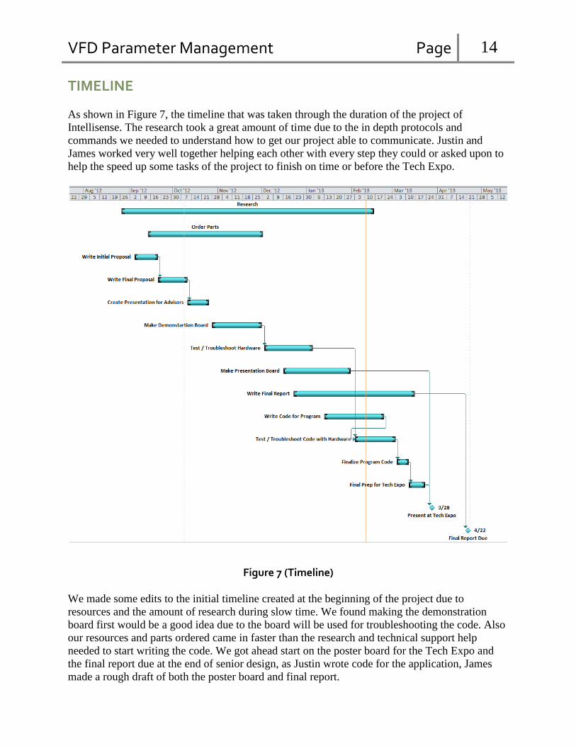
TIMELINE
As shown in Figure 7, the timeline that was taken through the duration of the project of
Intellisense. The research took a great amount of time due to the in depth protocols and
commands we needed to understand how to get our project able to communicate. Justin and
James worked very well together helping each other with every step they could or asked upon to
help the speed up some tasks of the project to finish on time or before the Tech Expo.
Figure 7 (Timeline)
We made some edits to the initial timeline created at the beginning of the project due to
resources and the amount of research during slow time. We found making the demonstration
board first would be a good idea due to the board will be used for troubleshooting the code. Also
our resources and parts ordered came in faster than the research and technical support help
needed to start writing the code. We got ahead start on the poster board for the Tech Expo and
the final report due at the end of senior design, as Justin wrote code for the application, James
made a rough draft of both the poster board and final report.

VFD Parameter Management Page 15
PROBLEMS ENCOUNTERED
Communication to VFDs
We were not entirely certain on how to be able to connect to the VFDs and which protocols were
needed. We sent some emails and got on phone with Brad communications technical support
hours on end. They offered a solution of a purchase of the Profibus module that will be able to
help with communication to the VFDs. After we figured out how to configure and setup the
module in we then were able to start the code and further our project. This was our biggest
hurdle to overcome.
Multiple parameters not being written
We found that when we were to send multiple parameters at once, some parameters would not
write to the VFDs. We then stepped through the code and found all the parameters write then
when we take our time and step through it. Then we decided to put a pause after each single
writings which helped to not jam up the Profibus module. This was an easy fix for us to find and
continue on with our troubleshooting.
Scanning the network
We were having issues with a function that will allow us to load a combo box with the available
slave addresses on the network for the user to be able to select. The function comes from the
Applicom.dll and does not allow us to step into the function when debugging to see what the
problem is. So far we can compile the code but then receive an error from the module stating that
one of my parameters is too large. We believe we have pin pointed it down to which parameter it
may be but am not completely certain. I can get the function to run when compiling it in standard
C. This problem has been fixed and was big for our project to continue.
VFD Parameter Management Page 16
FUTURE RECOMMENDATIONS
Compatibility with all VFDs
Having our application compatible with all VFDs that are made by the various manufactures will
ensure our project will and can be used by multiple companies or if the prior one becomes
discontinued in years to come our program will be able to compensate and still be used with
others. This compatibility will be very difficult to add because of the different hierarchy lists
used to set the parameters due to the different protocols to connect, read, and write to any
manufacturers VFD.
Retrieve feedback parameters
Being able to retrieve a parameter that is already entered in the VFD will be able to let the user
view and decide if the value needs to be changed. Also receiving live speeds and updates of what
is going on within the VFD will allow a user to be able to access faults and instantaneous values
to ensure proper functionality of the VFD. This will make our program to have complete control
over the system.
Add a profile
Adding a profile will be an easier task for add as an additional feature to the application. With
this feature we will be able to have the user create a profile based on the parameters he wants
that may be used on various locations. This will allow the user to click on the profile that has the
settings pre-entered and saved and just need to click send. This will save additional time because
the user will not need to click every individual parameter and type in the desired value rather the
values will needed will be typed in and saved for future uses.
Auto assigns slave address to every VFD on the network
This has been discussed within our group to be able to completely limit the engineer to
physically visiting each VFD. Having an auto assign will allow the user to not have to visit and
set this single parameter of slave address to be able to get sensed by the Profibus module. This is
very difficult to do because of each VFD defaulted to the same slave address and daisy chained
by the Profibus cable makes the Profibus module only see one slave address so the module only
thinks there is one VFD on the network. This means the parameters sent will be to every VFD on
the network without having the capability of being able to single out certain VFDs.

VFD Parameter Management Page 17
CONCLUSION
The final outcome of this project will solve the problem of placing employees in unsafe locations
as time management improvements. We feel that all of the goals, set by us and for us, were
exceeded. Our overall goal was to be able to access and communicate with PROFIBUS to
set/change the parameters in the VFDs to run the conveyor and sortation systems at the plant or
warehouses which is now possible. The potential to market to Intelligrated is a possibility for
their benefits for installation, and start making a profit in approximately two weeks of work.
Many of the future recommendations are already in process to maybe change the interface of the
application to an onsite engineer’s request. This project may be finished with respect to the
University of Cincinnati and Intelligrated.

VFD Parameter Management Page 18
REFERENCES
Intelligrated:
www.intelligrated.com
Charlton, Doug. Personal interview. 4 Oct. 2012
Saluke, Patrick. Personal interview. 1 Oct. 2012
Saluke, Patrick. Personal interview. 15 Oct. 2012
Simon, Peter. Personal interview. 13 Oct. 2012
Simon, Peter. Personal interview. 18 Oct. 2012
Uchtman, Rick. Personal interview. 1 Oct. 2012
Uchtman, Rick. Personal interview. 11 Oct. 2012
PROFIBUS:
www.woodhead.com
www.profibus.com
https://www.dropbox.com/s/fy8qkoeyodx8mwg/Brad%20Communications%20usb.pdf
https://www.dropbox.com/s/y9tellnkuiiuzrr/sw_Library_DLL.pdf
https://www.dropbox.com/s/2z7ke83puxwsept/pfb_usb.pdf
https://www.dropbox.com/s/wlhikfp4loycias/SVX9000%20PROFIBUS.pdf
https://www.dropbox.com/s/f3wa19t8xztd8m9/Differences%20between%20PFB3%20and%20P
CI.pdf
Cutler-Hammer VFD:
www.eaton.com
https://www.dropbox.com/s/ass231c7sy8s8dp/NEW%209000X%20Application%20Manual%20
-%20MN04004001E%5B1%5D.pdf
https://www.dropbox.com/s/wlhikfp4loycias/SVX9000%20PROFIBUS.pdf
https://www.dropbox.com/s/msg2ttd5j456ehd/SVX9000%20OPTION%20CARDS.pdf
https://www.dropbox.com/s/0ktmtprr1c31epp/SVX9000%20TECHNICAL%20DATA.pdf
https://www.dropbox.com/s/vlr6bv0udgii5vo/Cutler-
Hammer%20SVX9000%20and%20SPX9000%20Parameters-Standard.xls
VFD Parameter Management Page 19
APPENDIX A
INTELLISENSE CODE
INTELLISENSE
FULL CODE
CREATED BY JUSTIN BEST
SENIOR DESIGN 2013

VFD Parameter Management Page 20
// Intellisense
// Created By Justin Best
// University of Cincinnati Senior Design 2013
// Main form
using System;
using System.Collections.Generic;
using System.ComponentModel;
using System.Data;
using System.Drawing;
using System.Linq;
using System.Text;
using System.Windows.Forms;
using System.Diagnostics;
using System.Threading;
using ApplicomWra;
namespace Intellisense
{
public partial class Form1 : Form
{
// Instantiates form parametervalue & about
ParameterValue parametervalue = new ParameterValue();
About about = new About();
//// **********************************************************************
// *************** Globals Variables **********************************************
// **********************************************************************
// Brad Communications PROFIBUS module function variables
static short wNb = 6;
short wStatus;
int dwAdr = 0;
ushort wChan = 0;
ushort wNes;
short[] lpwTabl = new short[wNb]; // creates array with number of words setting length
string[] lpstrwriteTabl = new string[wNb]; // Table that all data is stored
string[] lpstrreadTabl = new string[wNb]; // Table that all data is stored
short[] lpwriteTabl = new short[wNb];
// UI global variables

VFD Parameter Management Page 21
Int16 userdatareturned;
int uservalueentries = 0;
int listboxindex = 0;
int runspeed;
int[] rowindexes = new int[10000]; // way overshot will never have this many parameters selected at a
time
bool suppresswarning = false;
bool form2open = false;
bool jumpover = false;
bool firstrowinque = false;
bool lastrowinque = false;
string start_stoptxt;
public Form1()
{
InitializeComponent();
// opens up PROFIBUS module software application "console"
Process openconsole = new Process();
openconsole.StartInfo.FileName = "C:\\Program Files\\BradCommunications\\PC Network
Interfaces\\4.1\\console.exe";
openconsole.Start();
// attempts to initialize the PROFIBUS module
AppliCom.initbus(out wStatus); // Opens communications with the module and Applicom.dll library
if (wStatus == 0)
{
toolStripStatusLabel1.Text = "Profibus module initialized successfully";
}
else
{
toolStripStatusLabel1.Text = "Profibus module NOT initialized successfully";
}

VFD Parameter Management Page 22
} // End of Public Form1
private void Form1_Load(object sender, EventArgs e)
{
int maxdrives = 126;
// TODO: This line of code loads data into the 'parameters1DataSet.VFD_Parameters' table. You can
move, or remove it, as needed.
this.vFD_ParametersTableAdapter.Fill(this.parameters1DataSet.VFD_Parameters);
// Function to load availableslaves combo box with the addresses programmed into the profibus
module
for (int i = 1; i < maxdrives; i++)
{
wNes = (ushort)(i);
for (int a = 1; a < 6; a++) //make into function as it will be done a lot!!!!!!
{
lpwTabl[0] = 8293;
lpwTabl[a] = 0;
} //end of inner for loop
// Profibus module write command
AppliCom.writeqword(ref wChan, ref wNes, ref wNb, ref dwAdr, lpwTabl, out wStatus); // write
data to VFD
if (wStatus == 0) // Write completed sucessfully
{
comboBox_availabledrives.Items.Add(wNes.ToString());
}
} // end of outter for loop
// Sets Max Frequency parameter value to 60.00 Hz so user can enter a Min frequency w/o receiving
an error
parameters1DataSet.VFD_Parameters.Rows[1].SetField(12, 6000);
// updates the dataset table

VFD Parameter Management Page 23
this.vFD_ParametersTableAdapter.Update(this.parameters1DataSet.VFD_Parameters);
comboBox_availabledrives.Focus();
}
// event that fires when a value within a datagridview is updated / changed
private void dataGridView_Parameters_CurrentCellDirtyStateChanged(object sender, EventArgs e)
{
// finializes any changes on datagridview so user can see reflected changes
if (dataGridView_Parameters.IsCurrentCellDirty)
{
dataGridView_Parameters.EndEdit();// updates current cell and ends edit mode
}
}
// event for when a value of a cell changes
private void dataGridView_Parameters_CellValueChanged(object sender, DataGridViewCellEventArgs e)
{
// when a check box is checked by the user
if (e.RowIndex > -1 && (Boolean)dataGridView_Parameters.Rows[e.RowIndex].Cells[1].Value == true)
// when form would load value of -1 would prevent if statement from working
{
// does not allow the parametervalue form to open again once a value is selected
if (form2open == false)
{
string allpresetvalues;
string[] presetvalues = new string[10000];
// int array to store row indexes choosen by the user
rowindexes[uservalueentries] = e.RowIndex;
parametervalue.StartPosition = FormStartPosition.CenterParent;
// sends to parametervalue form the text for opening text of the parameter the user has
selected along with any default values for that parameter
parametervalue.Labeltext =
dataGridView_Parameters.Rows[e.RowIndex].Cells[4].Value.ToString();
parametervalue.DataEntry =
dataGridView_Parameters.Rows[e.RowIndex].Cells["userInputDeviceDataGridViewTextBoxColumn"].Value.ToString();
parametervalue.Defaultval =
dataGridView_Parameters.Rows[e.RowIndex].Cells[8].Value.ToString();

VFD Parameter Management Page 24
// parses each string value and places into string array
allpresetvalues = dataGridView_Parameters.Rows[e.RowIndex].Cells[18].Value.ToString();
presetvalues = allpresetvalues.Split(',');
parametervalue.Presetvalues = presetvalues;
// Requires user to interact with the new form
parametervalue.ShowDialog();
form2open = false;
} // end of if statement line 137
} // end of if statement to see if check box is checked line 134
// when a checkbox is unchecked by the user
if (e.RowIndex > -1 && (Boolean)dataGridView_Parameters.Rows[e.RowIndex].Cells[1].Value == false)
// when form would load value of -1 would prevent if statement from working
{
// code here for once a value has been entered by user and placed in que but user de selects
it
if (jumpover != true)
{
// removes the value previously entered by the user
if (e.RowIndex != 1 && (int)dataGridView_Parameters.Rows[1].Cells[13].Value != 6000)
{
parameters1DataSet.VFD_Parameters.Rows[e.RowIndex].SetField(12, 0);
// in the user selected the Max Frequency param the default value is reissued
if (e.RowIndex == 1)
parameters1DataSet.VFD_Parameters.Rows[e.RowIndex].SetField(12, 6000);
}
// checks on the order of the que string array to determine how to renumber the remaining
queued selections
// check to see if the param being removed was the first item in the queue
if ((int)dataGridView_Parameters.Rows[e.RowIndex].Cells[19].Value == 0)
firstrowinque = true;
// check to see if the param being removed was the last item in the queue

VFD Parameter Management Page 25
if ((int)dataGridView_Parameters.Rows[e.RowIndex].Cells[19].Value ==
(dataGridView_Query.Rows.Count - 1))
lastrowinque = true;
dataGridView_Query.Rows.RemoveAt(Convert.ToInt16(dataGridView_Parameters.Rows[e.RowIndex].Cells[19].Value));
// needed because the event in line 131 will fire and the parametervalue form will attempt
to run
form2open = true;
jumpover = true;
parameters1DataSet.VFD_Parameters.Rows[e.RowIndex].SetField(17, DBNull.Value);
if (dataGridView_Query.Rows.Count >= 1)
{
// if the first row was removed, renumber all after row is removed
if (firstrowinque == true)
{
for (int z = 0; z < dataGridView_Parameters.Rows.Count; z++)
{
if (dataGridView_Parameters.Rows[z].Cells[19].Value != DBNull.Value)
{
parameters1DataSet.VFD_Parameters.Rows[z].SetField(17,
(int)(dataGridView_Parameters.Rows[z].Cells[19].Value) - 1);
//dataGridView_Parameters.Rows[z].Cells[19].Value =
((int)(dataGridView_Parameters.Rows[z].Cells[19].Value) - 1);
}
} // end of for if firstrow == true
firstrowinque = false;
} // end of if firstrow == true
// if last row was removed, do nothing but change value of lastrowinque
else if (lastrowinque == true)
VFD Parameter Management Page 26
{
lastrowinque = false;
}// end of else if lastrow == true
// if row is between first and last was removed, then renumber all except first row
else
{
for (int z = 0; z < dataGridView_Parameters.Rows.Count; z++)
{
if (dataGridView_Parameters.Rows[z].Cells[19].Value != DBNull.Value &&
(int)dataGridView_Parameters.Rows[z].Cells[19].Value != 0)
{
parameters1DataSet.VFD_Parameters.Rows[z].SetField(17,
(int)(dataGridView_Parameters.Rows[z].Cells[19].Value) - 1);
}
}
}// end of else when row in between is removed
// update dataset table adapter
this.vFD_ParametersTableAdapter.Update(this.parameters1DataSet.VFD_Parameters);
} // end of if statement when rows remain in que
// updates variable due to removal of rows
uservalueentries = (dataGridView_Query.Rows.Count);
// ensure send button is not enabled if no parameters are selected to send
if (dataGridView_Query.Rows.Count == 0)
button_sendque.Enabled = false;
// change back to false as the event will no longer be fired once all values have been
updated
form2open = false;
jumpover = false;
} // end of if statement
}
// User hits ok button on ParameterValue form and returns dialogresult.ok
if (parametervalue.DialogResult == System.Windows.Forms.DialogResult.OK)
{
VFD Parameter Management Page 27
// if no slave address has been selected bring focus to combo box to get user to select a
slave address
if (listBox_selectedslaves.Items.Count == 0)
comboBox_availabledrives.Focus();
string textuserentry;
bool showtext = false;
form2open = true;
// updates variable from what the user selected in the parametervalue form
userdatareturned = parametervalue.uservalue; // brings value entered from user in
ParameterValue form back to Form1
textuserentry = parametervalue.textuserval;
// uses the string value when shown in the queue (incorporates decimal to not confuse
user)
if (textuserentry.Length > 0)
showtext = true;
// string array for queue datagridview
string[] questr = new string[2]; // str array to display each qued user entry into the
datagridview
questr[0] = dataGridView_Parameters.Rows[e.RowIndex].Cells[4].Value.ToString();
// decimal version i.e 60.00
if (showtext == true)
questr[1] = textuserentry;
// non decimal version ie 6000
else if (showtext == false)
questr[1] = Convert.ToString(userdatareturned);
// adds in the new row to the datagrid
dataGridView_Query.Rows.Add(questr); // updates row in dgv que to display last parameter
selected by user with value
// updates the variable b/c it is used in a for loop later
uservalueentries = (dataGridView_Query.Rows.Count);
// updates the dialogresult back to none
parametervalue.DialogResult = DialogResult.None; // resets dialog result of parametervalue
form
// writes the user selected data to the dataset
parameters1DataSet.VFD_Parameters.Rows[e.RowIndex].SetField(12, userdatareturned);
VFD Parameter Management Page 28
parameters1DataSet.VFD_Parameters.Rows[e.RowIndex].SetField(17,
(dataGridView_Query.Rows.Count - 1));
//updates the datatable adapter to reflect the changes made to the dataset
this.vFD_ParametersTableAdapter.Update(this.parameters1DataSet.VFD_Parameters);
form2open = false;
// enables the send queue button once a parameter and a slave address are selected by the
user
if (dataGridView_Query.Rows.Count >= 1 && listBox_selectedslaves.Items.Count >= 1)
button_sendque.Enabled = true;
if (listBox_selectedslaves.Items.Count > 0)
button_sendque.Focus();
}// end of DialogResult.OK
// User hits cancel button or X on parametervalue form
if (parametervalue.DialogResult == System.Windows.Forms.DialogResult.Cancel)// |
parametervalue.ShowDialog() == System.Windows.Forms.DialogResult.Abort)
{
jumpover = true;
// makes value false which unchecks the box
dataGridView_Parameters.Rows[e.RowIndex].Cells[1].Value = false;
// resets dialog result of parametervalue form
parametervalue.DialogResult = DialogResult.None;
jumpover = false;
} // end of DialogResult.Cancel
} // end of cell value changed event line 131
// event for when the send queue button is clicked
private void button_sendque_Click(object sender, EventArgs e)
{
bool sendverified = false;

VFD Parameter Management Page 29
button_sendque.Enabled = false;
toolStripStatusLabel1.Text = "Sending Data";
Cursor.Current = Cursors.WaitCursor;
listboxindex = listBox_selectedslaves.Items.Count;
// most exterior for loop, this loop is used to send the parameters selected to the slave
address(s) selected
for (int i = 0; i < listboxindex; i++)
{
// slave address
wNes = (ushort)(dataGridView_Slaves.Rows[i].Cells[0].Value);
// middle for loop, this loop is used to create and send a table of the user selected
parameters and values
// based upon the number of parameters selected
for (int b = 0; b < dataGridView_Query.Rows.Count; b++) // for loop to send each parameter to
same VFD
{
// most interior loop, this loop is used to create each table or packet of data for each
parameter selected
// each packet of data is 12 bytes long containing the following:
// id number of parameter chosen
// value for the parameter chosen
// a run command (if applicable)
// value for run command (if applicable)
for (int a = 0; a < wNb; a++)
{
// switch / case statement used to build each packet of data to send to the selected
vfd
switch (a)
{
case 0:
lpwTabl[a] =
Convert.ToInt16(dataGridView_Parameters.Rows[rowindexes[b]].Cells[11].Value);
break;
case 1:
lpwTabl[a] =
Convert.ToInt16(dataGridView_Parameters.Rows[rowindexes[b]].Cells[12].Value);
break;
case 2:

VFD Parameter Management Page 30
lpwTabl[a] =
Convert.ToInt16(dataGridView_Parameters.Rows[rowindexes[b]].Cells[13].Value);
break;
case 3:
// if statements used to compensate for 2HP vfds that require more precision
(significant figures)
if (wNes == 10 &&
Convert.ToInt16(dataGridView_Parameters.Rows[rowindexes[b]].Cells[11].Value.ToString()) == 8299)
lpwTabl[a] =
Convert.ToInt16((Convert.ToInt32(dataGridView_Parameters.Rows[rowindexes[b]].Cells[14].Value) * 10));
else if (wNes == 20 &&
Convert.ToInt16(dataGridView_Parameters.Rows[rowindexes[b]].Cells[11].Value.ToString()) == 8299)
lpwTabl[a] =
Convert.ToInt16((Convert.ToInt32(dataGridView_Parameters.Rows[rowindexes[b]].Cells[14].Value) * 10));
else if (wNes == 40 &&
Convert.ToInt16(dataGridView_Parameters.Rows[rowindexes[b]].Cells[11].Value.ToString()) == 8299)
lpwTabl[a] =
Convert.ToInt16((Convert.ToInt32(dataGridView_Parameters.Rows[rowindexes[b]].Cells[14].Value) * 10));
else if (wNes == 10 &&
Convert.ToInt16(dataGridView_Parameters.Rows[rowindexes[b]].Cells[11].Value.ToString()) == 8305)
lpwTabl[a] =
Convert.ToInt16((Convert.ToInt32(dataGridView_Parameters.Rows[rowindexes[b]].Cells[14].Value) * 10));
else if (wNes == 20 &&
Convert.ToInt16(dataGridView_Parameters.Rows[rowindexes[b]].Cells[11].Value.ToString()) == 8305)
lpwTabl[a] =
Convert.ToInt16((Convert.ToInt32(dataGridView_Parameters.Rows[rowindexes[b]].Cells[14].Value) * 10));
else if (wNes == 40 &&
Convert.ToInt16(dataGridView_Parameters.Rows[rowindexes[b]].Cells[11].Value.ToString()) == 8305)
lpwTabl[a] =
Convert.ToInt16((Convert.ToInt32(dataGridView_Parameters.Rows[rowindexes[b]].Cells[14].Value) * 10));
else
{
VFD Parameter Management Page 31
lpwTabl[a] =
Convert.ToInt16(dataGridView_Parameters.Rows[rowindexes[b]].Cells[14].Value);
}
break;
case 4:
lpwTabl[a] =
Convert.ToInt16(dataGridView_Parameters.Rows[rowindexes[b]].Cells[15].Value);
break;
case 5:
lpwTabl[a] =
Convert.ToInt16(dataGridView_Parameters.Rows[rowindexes[b]].Cells[16].Value);
break;
} // end of switch / case ilne 360
} // end of inner for loop line 358
// Profibus module write function to send data packet to selected vfd
AppliCom.writeqword(ref wChan, ref wNes, ref wNb, ref dwAdr, lpwTabl, out wStatus); //
write data to VFD
// Write completed sucessfully
if (wStatus == 0)
{
// Puts main thread to sleep for 150msec to ensure all packets are sent successfully
Thread.Sleep(150);
toolStripStatusLabel1.Text = "Data Sent";
// places the data sent into another array to compare to the data read from the vfd to
validate parameters were sent successfully
lpwriteTabl = lpwTabl;
// once write is completed successfully a read will verify that the data was sent
successfully by comparing the values
// read last parameter sent to VFD
AppliCom.readqword(ref wChan, ref wNes, ref wNb, ref dwAdr, lpwTabl, out wStatus);
// read completed successfully
if (wStatus == 0)
{

VFD Parameter Management Page 32
// compares values from data written to data received and if equal
if (Object.Equals(lpwTabl, lpwriteTabl) == true)
sendverified = true;
else
sendverified = false;
} // end of if object equal statement line 426
// Function did not complete successfully
else
toolStripStatusLabel1.Text = Convert.ToString(wStatus);
} // end of write completed successfully if statement line 413
// Function did not complete successfully
else
toolStripStatusLabel1.Text = Convert.ToString(wStatus);
} // end of middle for loop line 349
} // end of exterior (multiple VFD) for loop line 342
if (sendverified == true)
{
Cursor.Current = Cursors.Default;
MessageBox.Show("Parameters have been sent successfully!");
form2open = true;
jumpover = true;
// unchecks all checked rows from dgv parameters
for (int z = 0; z < dataGridView_Parameters.Rows.Count; z++)
{
// sets value of check box to false, thus un checking the box programmatically
dataGridView_Parameters.Rows[rowindexes[z]].Cells[1].Value = false;
// all sent values are then zeroed out in dataset
parameters1DataSet.VFD_Parameters.Rows[z].SetField(12, 0);
parameters1DataSet.VFD_Parameters.Rows[z].SetField(17, DBNull.Value);
}
// resets default Max Frequency to 60.00 hz
parameters1DataSet.VFD_Parameters.Rows[1].SetField(12, 6000);
// updates table adapter to reflect changes made to dataset
VFD Parameter Management Page 33
this.vFD_ParametersTableAdapter.Update(this.parameters1DataSet.VFD_Parameters);
form2open = false;
jumpover = false;
// removes all rows in queue datagridview
dataGridView_Query.Rows.Clear();
// removes all rows in slave address datagridview
dataGridView_Slaves.Rows.Clear();
// updates variable
uservalueentries = (dataGridView_Query.Rows.Count);
// removes all items (slave addresses) from list box
listBox_selectedslaves.Items.Clear();
// updates counting variable from removal of listbox items
listboxindex = listBox_selectedslaves.Items.Count;
// un enables buttons to ensure user does not attempt to click
button_removeslave.Enabled = false;
button_start_stop.Enabled = false;
// places focus back onto available slave addresses to restart procedure
comboBox_availabledrives.Focus();
}// end of if sendverified == true line 328
else
{
// dialog box to inform user that parameters were not sent
MessageBox.Show("One or more parameters did not send successfully");
}
// Updates table adapter to display changes made to dataset
this.vFD_ParametersTableAdapter.Update(this.parameters1DataSet.VFD_Parameters);
}// end of send button
private void button_Exit_Click(object sender, EventArgs e)
{
// Updates table adapter to display changes made to dataset
this.vFD_ParametersTableAdapter.Update(this.parameters1DataSet.VFD_Parameters);
Application.Exit();
}
private void comboBox_availabledrives_SelectedIndexChanged(object sender, EventArgs e)

VFD Parameter Management Page 34
{
int index;
// string array
string [] newslaveaddress = new string [2];
// ensures that the user selects something
if (comboBox_availabledrives.Text.Length > 0)
{
// searches for the value selected by the user
index = listBox_selectedslaves.FindStringExact(comboBox_availabledrives.Text);
// if no match is found insert it into the list box
if (index == ListBox.NoMatches)
{
listBox_selectedslaves.Items.Add(comboBox_availabledrives.Text);
newslaveaddress[0] = comboBox_availabledrives.Text;
newslaveaddress[1] = Convert.ToString(listboxindex);
// adds new row into datagridview
dataGridView_Slaves.Rows.Add(newslaveaddress);
dataGridView_Slaves.Rows[listboxindex].Cells[0].Value =
Convert.ToUInt16(dataGridView_Slaves.Rows[listboxindex].Cells[0].Value);
if (dataGridView_Slaves.Rows.Count > 1)
{
// sorts the selected slave addresses in ascending order
dataGridView_Slaves.Sort(Address, ListSortDirection.Ascending);
for (int i = 0; i < dataGridView_Slaves.Rows.Count; i++)
{
// assigns row number to each row
dataGridView_Slaves.Rows[i].Cells[1].Value = i;
}
}
// updates variable
listboxindex = listBox_selectedslaves.Items.Count;
if (listBox_selectedslaves.Items.Count >= 1)
{
button_removeslave.Enabled = true;

VFD Parameter Management Page 35
button_start_stop.Enabled = true;
}
if (listBox_selectedslaves.Items.Count >= 1 && dataGridView_Query.Rows.Count >= 1)
button_sendque.Enabled = true;
} // end of if no matches statement line 523
// if a match is found, do nothing
else
return;
} // end of if (combobox_availabledrives.text
} // end of selected index event
private void button_removeslave_Click(object sender, EventArgs e)
{
if (listBox_selectedslaves.SelectedIndex >= 0)
{
// removes selected slave address from listbox and datagridview
dataGridView_Slaves.Rows.RemoveAt(listBox_selectedslaves.SelectedIndex);
listBox_selectedslaves.Items.RemoveAt(listBox_selectedslaves.SelectedIndex);
form2open = true;
jumpover = true;
if (dataGridView_Slaves.Rows.Count >= 1)
{
// resorts remaining slaved address(s) in listbox
dataGridView_Slaves.Sort(Address, ListSortDirection.Ascending);
for (int i = 0; i < dataGridView_Slaves.Rows.Count; i++)
{
// re issues row number
dataGridView_Slaves.Rows[i].Cells[1].Value = i;
}
}
// updates variable
VFD Parameter Management Page 36
listboxindex = listBox_selectedslaves.Items.Count;
form2open = false;
jumpover = false;
// checks to ensure send and remove buttons are enabled if criteria is met
if (listBox_selectedslaves.Items.Count == 0)
button_removeslave.Enabled = false;
if (listBox_selectedslaves.Items.Count < 1 || dataGridView_Query.Rows.Count > 1)
button_sendque.Enabled = false;
} // if statement from line 560
if (listBox_selectedslaves.Items.Count == 0)
button_start_stop.Enabled = false;
} // end of button_removeslaves click event line 557
private void aboutToolStripMenuItem_Click(object sender, EventArgs e)
{
// displays about form with app information
about.StartPosition = FormStartPosition.CenterParent;
about.ShowDialog();
}
private void Form1_FormClosing(object sender, FormClosingEventArgs e)
{
form2open = true;
jumpover = true;
// unchecks all checked rows from dgv parameters
for (int z = 0; z < dataGridView_Parameters.Rows.Count; z++)
{
dataGridView_Parameters.Rows[rowindexes[z]].Cells[1].Value = false;
parameters1DataSet.VFD_Parameters.Rows[z].SetField(12, 0);
parameters1DataSet.VFD_Parameters.Rows[z].SetField(17, DBNull.Value);
}
form2open = false;
jumpover = false;
// updates datagridview to reflect changes made to dataset
this.vFD_ParametersTableAdapter.Update(this.parameters1DataSet.VFD_Parameters);

VFD Parameter Management Page 37
}
// event fired when start vfd button is clicked
// runs small motor attached to demo vfd slave address 40
private void button_start_Click(object sender, EventArgs e)
{
bool start = false;
bool stop = false;
bool verified = false;
Int16 multiplevar = 0;
Int16 paranumb = 0;
double percentage = 0;
// changes the text for the button and label since button is used for dual purpose (start & stop)
if(label_start_stop.Text == "Start Motor" && button_start_stop.Text == "Start")
start = true;
else
stop = true;
// user has selected to start the motor on vfd #4
if (start == true)
{
paranumb = 1151;
start_stoptxt = "Drive(s) Running";
// error checking code to ensure a vfd was selected
if (listBox_selectedslaves.Items.Count < 1)
return;
toolStripStatusLabel1.Text = "";
listboxindex = listBox_selectedslaves.Items.Count;
// instantiates form driverun
DriveRun driverun = new DriveRun();
driverun.StartPosition = FormStartPosition.CenterParent;
driverun.supressed = suppresswarning;
// form driverun requires input from the user before it will close
driverun.ShowDialog();
// user has selected to close the form either by pressing the "x" or cancel button
if (driverun.DialogResult == System.Windows.Forms.DialogResult.Cancel)
{ // returns value if user has selected to suppress the warning everytime the driverun form
opens

VFD Parameter Management Page 38
suppresswarning = driverun.supressed;
listBox_selectedslaves.Items.Clear();
dataGridView_Slaves.Rows.Clear();
listboxindex = listBox_selectedslaves.Items.Count;
// disables the button until a slave address is selected
button_start_stop.Enabled = false;
return;
}
// user has entered a value on form driverun and has hit the "ok" button
if (driverun.DialogResult == System.Windows.Forms.DialogResult.OK)
{
suppresswarning = driverun.supressed;
runspeed = driverun.runfreq;
multiplevar = Convert.ToInt16(runspeed);
// Max frequency for vfd #4 will be set to 50Hz to not potentially damage motor
// user selected value will be divided by 5000 or 50.00 Hz to get percentage
percentage = Convert.ToDouble(multiplevar) / 5000;
percentage = percentage * 10000;
// sets up button to be used to stop motor
label_start_stop.Text = "Stop Motor";
button_start_stop.Text = "Stop";
} // end of dialog result == OK
} // end of if (start == true)line 641
// user has selected to stop currently running vfd
else if (stop == true)
{
multiplevar = 0;
paranumb = 1150;
percentage = 0;
start_stoptxt = "Drive(s) Stopped";
label_start_stop.Text = "Start Motor";
button_start_stop.Text = "Start";
}
// loop used for stopping and starting motor
// exterior for loop used to send start/stop to all drives selected
for (int i = 0; i < listboxindex; i++)
{
// slave address selected by user
wNes = (ushort)(dataGridView_Slaves.Rows[i].Cells[0].Value);

VFD Parameter Management Page 39
// interior loop used to build packet of data to send to each slave address
for (int a = 0; a < wNb; a++)
{
switch (a)
{
case 0:
lpwTabl[a] = 8193;
break;
case 1:
lpwTabl[a] = 0;
break;
case 2:
lpwTabl[a] = 0;
break;
case 3:
lpwTabl[a] = multiplevar ; // value entered by user
break;
case 4:
lpwTabl[a] = paranumb;
break;
case 5:
lpwTabl[a] = Convert.ToInt16(percentage);
break;
} // end of switch / case
} // end of inner for loop line 701
AppliCom.writeqword(ref wChan, ref wNes, ref wNb, ref dwAdr, lpwTabl, out wStatus); //
write data to VFD
if (wStatus == 0) // Write completed sucessfully
{
// puts main thread to sleep to ensure data is sent to all selected slave
addresses
Thread.Sleep(150);
lpwriteTabl = lpwTabl;

VFD Parameter Management Page 40
// once write is completed successfully a read will verify that the data was sent
successfully by comparing the values
AppliCom.readqword(ref wChan, ref wNes, ref wNb, ref dwAdr, lpwTabl, out wStatus);
// read last parameter sent to VFD
if (wStatus == 0) // read completed successfully
{
// compares values from data written to data received and if equal
if (Object.Equals(lpwTabl, lpwriteTabl) == true)
{
verified = true;
}
else
verified = false;
} // end of if object equal statement
else // Function did not complete successfully
toolStripStatusLabel1.Text = Convert.ToString(wStatus);
} // end of write completed successfully if statement line 731
else // Function did not complete successfully
toolStripStatusLabel1.Text = Convert.ToString(wStatus);
} // end of multiple VFD for loop line 696
// read function has confirmed that data read matches data that was sent
if (verified == true)
{
toolStripStatusLabel1.Text = start_stoptxt;
dataGridView_Slaves.Rows.Clear();
listBox_selectedslaves.Items.Clear();
listboxindex = listBox_selectedslaves.Items.Count;
button_removeslave.Enabled = false;
button_start_stop.Enabled = false;
}// end of if sendverified == true
}// end of button_start_stop click event line 624

VFD Parameter Management Page 41
// file-> restore defaults option in tool strip
// automatically selects every parameter and it's factory default in the parameters list and prompts
user to select VFD
private void restoreDefaultsToolStripMenuItem_Click(object sender, EventArgs e)
{
int index = 0;
int numberindex = 0;
string strdefaultval;
string strdefaultnodecimal;
for (int a = 0; a < dataGridView_Parameters.Rows.Count; a++)
{
form2open = true;
rowindexes[uservalueentries] = a;
dataGridView_Parameters.Rows[a].Cells[1].Value = true;
strdefaultval = dataGridView_Parameters.Rows[a].Cells[8].Value.ToString();
// checks first to see if value has a decimal point
index = strdefaultval.IndexOf('.');
// value does have a decimal and will be an integer value
if (index >= 0 && strdefaultval.Length > 1)
{
strdefaultnodecimal = strdefaultval.Remove(index,1);
userdatareturned = Convert.ToInt16(strdefaultnodecimal);
}
// value does not have a decimal but needs to be checked to determine rather text or value
else
{
char[] numbers = { '1', '2', '3', '4', '5', '6', '7', '8', '9', '0' };
numberindex = strdefaultval.IndexOfAny(numbers);
// value is an integer value with no decimal point
if (numberindex >= 0)
{
userdatareturned =Convert.ToInt16(strdefaultval);
}

VFD Parameter Management Page 42
// value is a confirmed string word such as keypad or profibus
else
{
string labeltext = dataGridView_Parameters.Rows[a].Cells[4].Value.ToString();
if (labeltext == "Local Control Place" && strdefaultval == "Keypad")
userdatareturned = 2;
else if (labeltext == "Remote Control Place" && strdefaultval == "Fieldbus")
userdatareturned = 3;
else if (labeltext == "Local Reference" && strdefaultval == "Keypad")
userdatareturned = 2;
else if (labeltext == "Remote Reference" && strdefaultval == "Fieldbus")
userdatareturned = 3;
else if (labeltext == "Brake Chopper" && strdefaultval == "Not Used")
userdatareturned = 0;
else if (labeltext == "Stop Function" && strdefaultval == "Coasting")
userdatareturned = 0;
} // end of interior else
} // end of exterior else line 804
string[] questr = new string[2]; // str array to display each qued user entry into the
datagridview
questr[0] = dataGridView_Parameters.Rows[a].Cells[4].Value.ToString();
questr[1] = strdefaultval;
dataGridView_Query.Rows.Add(questr); // updates row in dgv que to display last parameter
selected by user with value
uservalueentries = (dataGridView_Query.Rows.Count);
parameters1DataSet.VFD_Parameters.Rows[a].SetField(12,userdatareturned );
parameters1DataSet.VFD_Parameters.Rows[a].SetField(17, (dataGridView_Query.Rows.Count - 1));
form2open = false;
this.vFD_ParametersTableAdapter.Update(this.parameters1DataSet.VFD_Parameters);
} // end of for loop line 785
if (dataGridView_Query.Rows.Count >= 1 && listBox_selectedslaves.Items.Count >= 1)
button_sendque.Enabled = true;

VFD Parameter Management Page 43
if (listBox_selectedslaves.Items.Count > 0)
button_sendque.Focus();
} // end of restoredefaults functions line 778
} // end of public partial class Form1 : Form
} // end of namespace Intellisense

VFD Parameter Management Page 44
// Intellisense
// Created By Justin Best
// form used to retrieve values for parameters selected by user
// ParameterValue form
using System;
using System.Collections.Generic;
using System.ComponentModel;
using System.Data;
using System.Drawing;
using System.Linq;
using System.Text;
using System.Windows.Forms;
namespace Intellisense
{
public partial class ParameterValue : Form
{
private string labeltext;
private string dataentry;
private string defaultval;
private string[] presetvalues;
int length = 0;
int beforedecimal;
bool nonnumberentered = false;
bool clickedok = false;
// saves value once user enters it from numeric up/down or combo box
public Int16 uservalue;
// used to display in que for the "text" value selected by the user when applicable
public string textuserval = null;
// gets text from dgv column 5 of form1 to fill label of corresponding parameter
public string Labeltext
{
get { return labeltext; }
set { labeltext = value; }
}
// gets text from dgv column 18 of form1 to determine rather to show the numeric up down or combo box
VFD Parameter Management Page 45
public string DataEntry
{
get { return dataentry; }
set { dataentry = value; }
}
public string[] Presetvalues
{
get { return presetvalues; }
set { presetvalues = value;}
}
public string Defaultval
{
get { return defaultval; }
set { defaultval = value; }
}
public DataTable error = new DataTable();
public ParameterValue()
{
InitializeComponent();
} // End of ParameterValue form
private void ParameterValue_Load(object sender, EventArgs e)
{
// TODO: This line of code loads data into the 'parameters1DataSet.Error_Checking' table. You can
move, or remove it, as needed.
this.error_CheckingTableAdapter.Fill(this.parameters1DataSet.Error_Checking);
// TODO: This line of code loads data into the 'parameters1DataSet.VFD_Parameters' table. You can
move, or remove it, as needed.
this.vFD_ParametersTableAdapter.Fill(this.parameters1DataSet.VFD_Parameters);
// TODO: This line of code loads data into the 'parameters1DataSet4.Table1' table. You can move,
or remove it, as needed.
string [] sigfig = new string [2];
string [] values = new string [1000];

VFD Parameter Management Page 46
comboBox_uservalue.Enabled = true;
comboBox_uservalue.Visible = true;
comboBox_uservalue.Items.AddRange(presetvalues);
comboBox_uservalue.Text = defaultval;
comboBox_uservalue.TabIndex = 0;
buttonOK.Visible = true;
buttonOK.Enabled = false;
buttonCancel.Visible = true;
if (comboBox_uservalue.Text.Length > 0)
buttonOK.Enabled = true;
label_parameterdesc.Text = labeltext;
} // end of ParameterValue_Load event line 67
private void buttonOK_Click(object sender, EventArgs e)
{
bool dataok = true;
if (comboBox_uservalue.Enabled == true)
{
dataok = errorchecking(comboBox_uservalue.Text);
if (dataok == false)
{
comboBox_uservalue.Text = "";
comboBox_uservalue.TabIndex = 0;
comboBox_uservalue.Focus();
comboBox_uservalue.DropDownStyle = ComboBoxStyle.DropDownList;
return;
}
}
comboBox_uservalue.Items.Clear();
clickedok = true;
this.DialogResult = System.Windows.Forms.DialogResult.OK;
}
private void buttonCancel_Click(object sender, EventArgs e)
VFD Parameter Management Page 47
{
// returns user has hit the cancel button
comboBox_uservalue.Items.Clear();
this.DialogResult = System.Windows.Forms.DialogResult.Cancel;
}
private void comboBox_uservalue_KeyPress(object sender, KeyPressEventArgs e)
{
if (nonnumberentered == true)
{
e.Handled = true;
nonnumberentered = false;
}
}
private void comboBox_uservalue_KeyDown(object sender, KeyEventArgs e)
{
if (e.KeyCode < Keys.D0 || e.KeyCode > Keys.D9)
{
if (e.KeyCode == Keys.Back || e.KeyCode == Keys.Delete)
return;
if (e.KeyCode == Keys.OemPeriod || e.KeyCode == Keys.Decimal)
{
if (comboBox_uservalue.Text.IndexOf('.') == -1)
return;
}
if (e.KeyCode < Keys.NumPad0 || e.KeyCode > Keys.NumPad9)
{
nonnumberentered = true;
}
}
else if (Control.ModifierKeys == Keys.Shift)
nonnumberentered = true;
if (nonnumberentered != true && e.Handled == true)

VFD Parameter Management Page 48
{
e.Handled = false;
}
if (nonnumberentered == false)
buttonOK.Enabled = true;
}
private void comboBox_uservalue_SelectedIndexChanged(object sender, EventArgs e)
{
int index;
int longestlength = 0;
string nodecimal;
string [] values = new string [2];
string [] maskedtxbox = new string [10];
bool skip = false;
if (comboBox_uservalue.Text.Length > 0)
{
buttonOK.Enabled = true;
if (comboBox_uservalue.Text == "[Custom]")
{
buttonOK.Enabled = false;
buttonOK.Visible = false;
buttonCancel.Visible = false;
for (int i = 0; i < presetvalues.Length; i++)
{
if (presetvalues[i] == "[Custom]")
break;
// checks to see if value has a decimal
index = presetvalues[i].IndexOf(".");
if (index >= 0)
{
nodecimal = presetvalues[i].Remove(index,1);
length = nodecimal.Length;
if (longestlength == 0)

VFD Parameter Management Page 49
longestlength = length;
if (length > longestlength)
longestlength = length;
values = presetvalues[i].Split('.');
beforedecimal = values[0].Length;
// sets mask for masked textbox from largest value in selection
for (int p = 1; p < beforedecimal; p++)
{
maskedtxbox[0] = "9";
maskedtxbox[p] = "0";
}
maskedtxbox[beforedecimal] = ".";
for (int q = (beforedecimal+1); q <= length; q++)
{
maskedtxbox[q] = "0";
}
if (maskedtxbox[0] == null)
maskedtxbox[0] = "9";
} // of if (index > 0)
else if (index < 0)
{
if (Convert.ToInt16(presetvalues[i]) == 0)
skip = true;
if (skip == false)
{
length = presetvalues[i].Length;
if (i == 0)
longestlength = length;
if (length > longestlength)
longestlength = length;
VFD Parameter Management Page 50
beforedecimal = longestlength;
for (int p = 0; p < beforedecimal; p++)
{
maskedtxbox[p] = "0";
}
} // end of if statement line 229
skip = false;
}// end of else if statement
} // end of for loop line 185
maskedTextBox_userentry.Mask = string.Join("", maskedtxbox);
maskedtxbox = null;
maskedTextBox_userentry.Visible = true;
maskedTextBox_userentry.Text = "";
comboBox_uservalue.Visible = false;
button_maskedok.Visible = true;
button_maskedcancel.Visible = true;
maskedTextBox_userentry.TabIndex = 0;
maskedTextBox_userentry.Focus();
} // end of if line 179
} // end of if statement line 175
} // end of comboBox_uservalue_SelectedIndexChanged event line 166
// function to check for errors on user selected value
private bool errorchecking(string userenteredval)
{
string strnodecimal;
int decimalindex = 0;
int numberindex = 0;
bool dataok1 = true;
// checks first of all to see if value has a decimal
decimalindex = comboBox_uservalue.Text.IndexOf('.');

VFD Parameter Management Page 51
// value does have a decimal and will be an integer value
if (decimalindex >= 0 && comboBox_uservalue.Text.Length > 1)
{
strnodecimal = comboBox_uservalue.Text.Remove(decimalindex, 1);
uservalue = Convert.ToInt16(strnodecimal);
textuserval = comboBox_uservalue.Text;
dataok1 = greaterorless(uservalue);
if (dataok1 == false)
return false;
else
return true;
}
// value does not have a decimal but needs to be checked to see if it is an actual integer value
else //if (decimalindex == -1)
{
char[] numbers = { '1', '2', '3', '4', '5', '6', '7', '8', '9', '0' };
numberindex = comboBox_uservalue.Text.IndexOfAny(numbers);
textuserval = comboBox_uservalue.Text;
// value has been verified that it is an integer value
if (numberindex >= 0 && comboBox_uservalue.Text.Length > 0)
{
uservalue = Convert.ToInt16(comboBox_uservalue.Text);
dataok1 = greaterorless(uservalue);
if (dataok1 == false)
return false;
else
return true;
}
// value is a confirmed string value selected from drop down box (IE keyboard or enable...)
else if (numberindex < 0 && comboBox_uservalue.Text.Length > 0)
VFD Parameter Management Page 52
{
//using square brackets because I have spaces between Parameter and Name DON'T DO THAT
NEXT TIME
string search1 = "[Parameter Name] ='" + labeltext + "'AND [Parameter Selected] ='" +
userenteredval + "'";
DataRow[] foundit = parameters1DataSet.Error_Checking.Select(search1);
uservalue = Convert.ToInt16(foundit[0]["Numerical Value"]);
textuserval = comboBox_uservalue.Text;
return true;
}
// value is just a single decimal point
else
MessageBox.Show("Please enter a value more than just a decimal point");
return false;
}// end of else from line 297
}// end of error checking function line 269
// additional error checking to ensure value selected by user does not exceed maximum input value
private bool greaterorless(int uservalue1)
{
if (labeltext == dataGridView_Parameterscheck.Rows[0].Cells[0].Value.ToString()
&& uservalue1 >
Convert.ToInt16(dataGridView_Parameterscheck.Rows[1].Cells[3].Value.ToString()))
{
MessageBox.Show("The value you have entered is greater than the Maximum value allowed");
return false;
}
else if (labeltext == dataGridView_Parameterscheck.Rows[1].Cells[0].Value.ToString() && uservalue1
> 10000)
{
MessageBox.Show("The value you have entered is greater than the Maximum value allowed");
return false;
}
else if (labeltext == dataGridView_Parameterscheck.Rows[9].Cells[0].Value.ToString() && uservalue1
> 100)

VFD Parameter Management Page 53
{
MessageBox.Show("The value you have entered is greater than the Maximum value allowed");
return false;
}
else if ((labeltext == dataGridView_Parameterscheck.Rows[1].Cells[0].Value.ToString())
&& uservalue1 < Convert.ToInt16(dataGridView_Parameterscheck.Rows[0].Cells[3].Value.ToString()))
{
MessageBox.Show("The value you have entered is less than the Minimum value allowed");
return false;
}
else if (labeltext == dataGridView_Parameterscheck.Rows[6].Cells[0].Value.ToString() && uservalue1
> 32000)
{
MessageBox.Show("The value you have entered is greater than the Maximum value allowed");
return false;
}
else
return true;
}// end of greaterorless function line 337
private void button_maskedcancel_Click(object sender, EventArgs e)
{
maskedTextBox_userentry.Text = "";
maskedTextBox_userentry.Visible = false;
button_maskedcancel.Visible = false;
button_maskedok.Visible = false;
comboBox_uservalue.Visible = true;
comboBox_uservalue.Text = "";
buttonOK.Visible = true;
buttonCancel.Visible = true;
}
private void button_maskedok_Click(object sender, EventArgs e)
{
maskedTextBox_userentry.Visible = false;
button_maskedok.Visible = false;
button_maskedcancel.Visible = false;
comboBox_uservalue.DropDownStyle = ComboBoxStyle.DropDown;

VFD Parameter Management Page 54
comboBox_uservalue.Text = maskedTextBox_userentry.Text;
comboBox_uservalue.Visible = true;
buttonCancel.Visible = true;
buttonOK.Visible = true;
buttonOK.Enabled = true;
buttonOK.Focus();
maskedTextBox_userentry.Text = "";
}
private void maskedTextBox_userentry_TextChanged(object sender, EventArgs e)
{
string input = maskedTextBox_userentry.Text;
int index = input.IndexOf('.');
if (index >= 0)
input = input.Remove(index, 1);
if (input.Length == length)
button_maskedok.Enabled = true;
else
button_maskedok.Enabled = false;
}
private void ParameterValue_FormClosing(object sender, FormClosingEventArgs e)
{
if (clickedok != true)
{
// returns that the use hit the cancel button
comboBox_uservalue.Items.Clear();
this.DialogResult = System.Windows.Forms.DialogResult.Cancel;
}
clickedok = false;
}
} // end of partial form 1
} // end of namespace Intellisense

VFD Parameter Management Page 55
// Intellisense
// Created By Justin Best
// form used to retrieve user selected speed for starting motor
// Driverun form
using System;
using System.Collections.Generic;
using System.ComponentModel;
using System.Data;
using System.Drawing;
using System.Linq;
using System.Text;
using System.Windows.Forms;
namespace Intellisense
{
public partial class DriveRun : Form
{
bool hitok = false;
public bool supressed;
public int runfreq = 0;
public DriveRun()
{
InitializeComponent();
}
private void DriveRun_Load(object sender, EventArgs e)
{
if (supressed != true)
{
textBox_warning.Visible = true;
textBox_warning.BringToFront();
timer_warning.Enabled = true;
timer_warning.Interval = 7000;
timer_warning.Start();
}
else

VFD Parameter Management Page 56
{
textBox_warning.Visible = false;
textBox_warning.SendToBack();
maskedTextBox_userfreq.Focus();
}
}
private void button_Drive_Cancel_Click(object sender, EventArgs e)
{
DialogResult = DialogResult.Cancel;
}
private void DriveRun_FormClosing(object sender, FormClosingEventArgs e)
{
if (hitok != true)
{
DialogResult = DialogResult.Cancel;
}
hitok = false;
}
private void button_Drive_OK_Click(object sender, EventArgs e)
{
string nodecimal;
int index = 0;
if (maskedTextBox_userfreq.Text.Length > 0)
{
index = maskedTextBox_userfreq.Text.IndexOf(".");
nodecimal = maskedTextBox_userfreq.Text.Remove(index, 1);
if (Convert.ToInt32(nodecimal) > 5000)
{
maskedTextBox_userfreq.Text = "";
maskedTextBox_userfreq.Mask = "90.00";
MessageBox.Show("The value enterd is larger than the maximum frequency of 50.00 Hz");

VFD Parameter Management Page 57
maskedTextBox_userfreq.Focus();
return;
}
else
{
runfreq = Convert.ToInt32(nodecimal);
hitok = true;
DialogResult = DialogResult.OK;
}
} // end of if statement line 71
} // end of button click event line 66
private void maskedTextBox_userfreq_TextChanged(object sender, EventArgs e)
{
string input = maskedTextBox_userfreq.Text;
int index = input.IndexOf('.');
int length = 3;
if (index >= 0)
input = input.Remove(index, 1);
if (input.Length > length)
button_Drive_OK.Enabled = true;
else
button_Drive_OK.Enabled = false;
}
private void checkedListBox_supresswarning_SelectedIndexChanged(object sender, EventArgs e)
{
if (checkedListBox_supresswarning.CheckedItems.Count != 0)
{
supressed = true;
timer_warning.Stop();
timer_warning.Enabled = false;
textBox_warning.SendToBack();
textBox_warning.Visible = false;
maskedTextBox_userfreq.Focus();

VFD Parameter Management Page 58
}
else
{
supressed = false;
}
}
private void checkedListBox_supresswarning_ItemCheck(object sender, ItemCheckEventArgs e)
{
}
private void timer_warning_Tick(object sender, EventArgs e)
{
timer_warning.Stop();
timer_warning.Enabled = false;
textBox_warning.SendToBack();
textBox_warning.Visible = false;
maskedTextBox_userfreq.Focus();
}
} // end of public partical class
} // end of namespace Intellisense
VFD Parameter Management Page 59
// Intellisense
// Created By Justin Best
// form used to display information about the app
// About form
using System;
using System.Collections.Generic;
using System.ComponentModel;
using System.Data;
using System.Drawing;
using System.Linq;
using System.Text;
using System.Windows.Forms;
using System.Diagnostics;
namespace Intellisense
{
public partial class About : Form
{
public About()
{
InitializeComponent();
}
private void About_Load(object sender, EventArgs e)
{
string productname = "Intellisense";
string companyname = "Justin Best, James Pignatiello";
string version = "Version 1.1";
string copyright = "Copyright 2013";
label_Credit.Text = productname + "\n"
+ companyname + "\n"
+ version + "\n"
+ Application.CurrentInputLanguage.Culture.EnglishName
+ "\n" + copyright;
}
private void linkLabel_justin_LinkClicked(object sender, LinkLabelLinkClickedEventArgs e)
VFD Parameter Management Page 60
{
string address = "[email protected]";
string subject = "Intellisense VFD management";
Process.Start(string.Format("mailto:{0}?subject={1}", address, subject));
}
private void linkLabel_james_LinkClicked(object sender, LinkLabelLinkClickedEventArgs e)
{
string address = "[email protected]";
string subject = "Intellisense VFD management";
Process.Start(string.Format("mailto:{0}?subject={1}", address, subject));
}
} // end of public partial class
} // end of namespace Intellisense

VFD Parameter Management Page 61
APPENDIX B
PHOTOGRAPHS
Initial Layout of Demonstration Board Drilling holes in Board for hardware components
Painted board and bolted hardware components Bent conduit and placed from trough to hardware components
Wired components for power and PROFIBUS Wired power supply

VFD Parameter Management Page 62
Finished Demonstration Board
Technical Exposition

VFD Parameter Management Page 63
APPENDIX C
SCHEMATICS

VFD Parameter Management Page 64
Symbols and Notes
Š

VFD Parameter Management Page 65

VFD Parameter Management Page 66

VFD Parameter Management Page 67
Š
Power Supply
MFG:
CAT
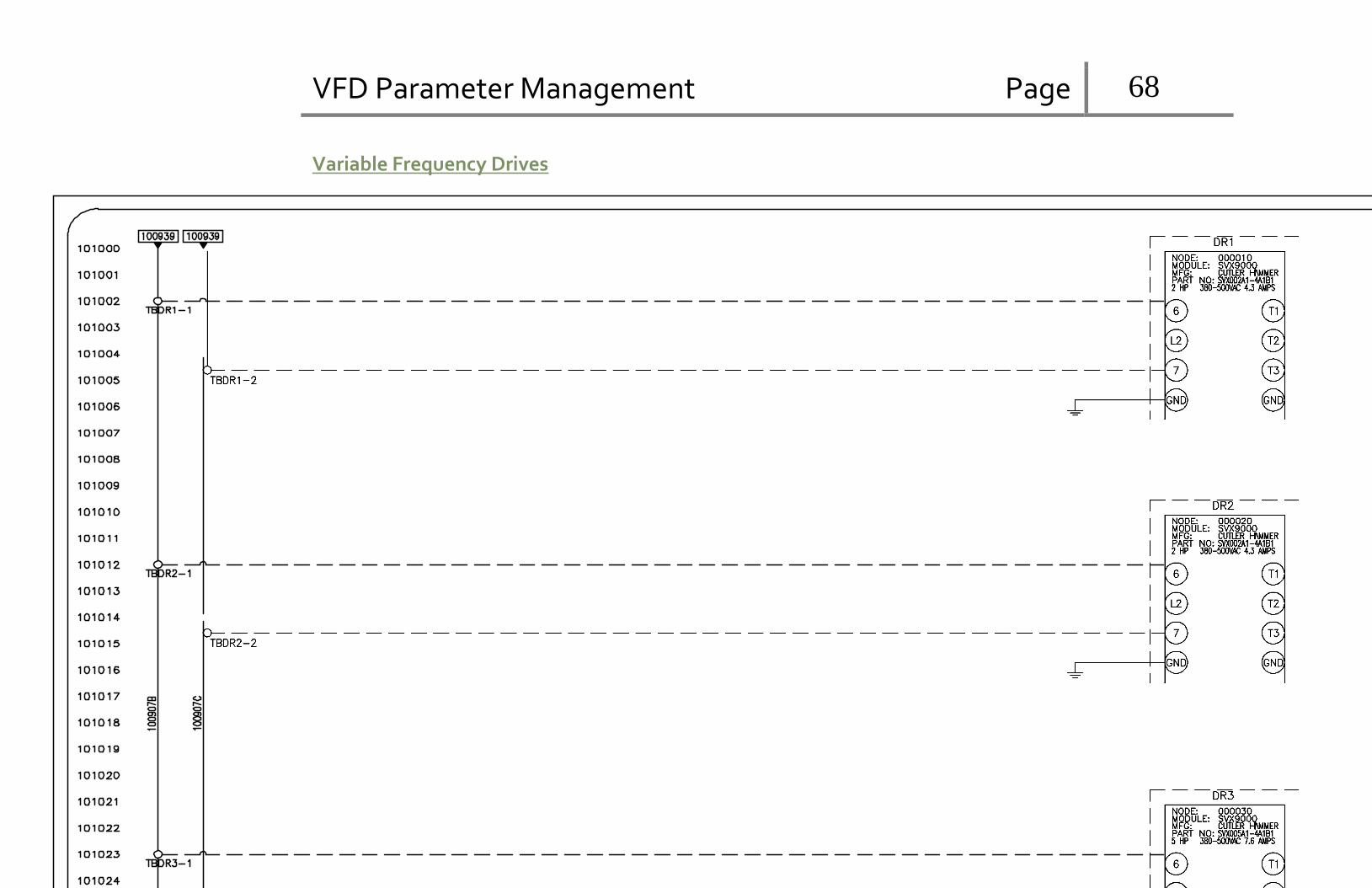
VFD Parameter Management Page 68
Š
Variable Frequency Drives

VFD Parameter Management Page 69
Repeater and Terminator
PFBC0000-4GRN
PFBC0000-4RED
PFBC0000-3GRN
PFBC0000-3RED
TERM1
PFBC0000-6GRN
PFBC0000-6RED

VFD Parameter Management Page 70
Power Supply Panel Layout

VFD Parameter Management Page 71
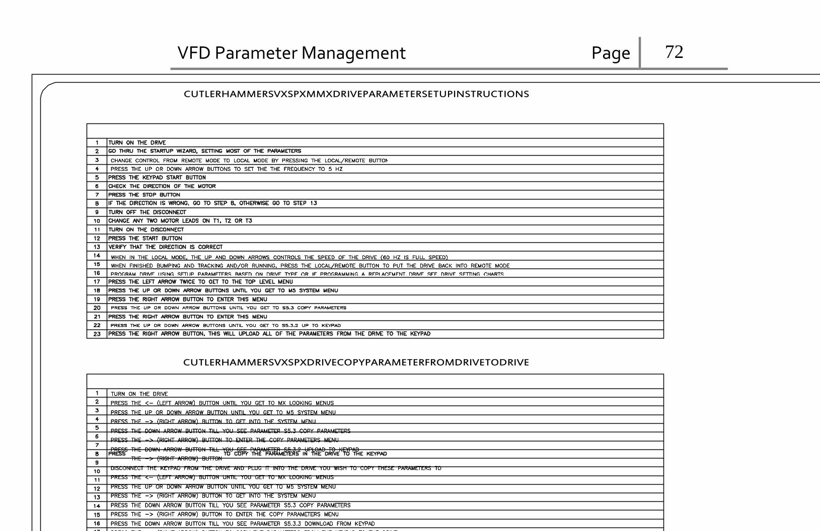
VFD Parameter Management Page 72
Š
CUTLERHAMMERSVXSPXMMXDRIVEPARAMETERSETUPINSTRUCTIONS
CUTLERHAMMERSVXSPXDRIVECOPYPARAMETERFROMDRIVETODRIVE

VFD Parameter Management Page 73
Š
CUTLERHAMMERSVXPARAMETERS

VFD Parameter Management Page 74
PROFIBUS Module

VFD Parameter Management Page 75
DATASHEETS Variable Frequency Drive
Application Manual
Effective August 2010
Supersedes January 2010

VFD Parameter Management Page 76
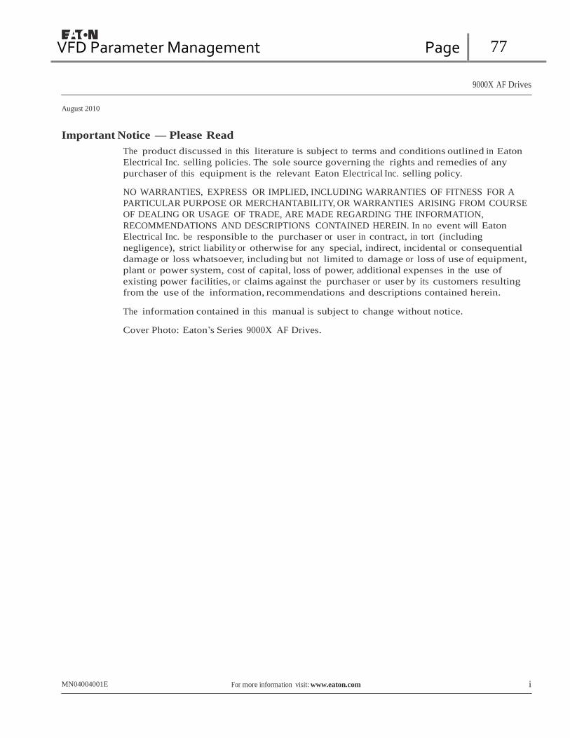
VFD Parameter Management Page 77
9000X AF Drives
August 2010
Important Notice — Please Read
The product discussed in this literature is subject to terms and conditions outlined in Eaton
Electrical Inc. selling policies. The sole source governing the rights and remedies of any
purchaser of this equipment is the relevant Eaton Electrical Inc. selling policy.
NO WARRANTIES, EXPRESS OR IMPLIED, INCLUDING WARRANTIES OF FITNESS FOR A
PARTICULAR PURPOSE OR MERCHANTABILITY, OR WARRANTIES ARISING FROM COURSE
OF DEALING OR USAGE OF TRADE, ARE MADE REGARDING THE INFORMATION,
RECOMMENDATIONS AND DESCRIPTIONS CONTAINED HEREIN. In no event will Eaton
Electrical Inc. be responsible to the purchaser or user in contract, in tort (including
negligence), strict liability or otherwise for any special, indirect, incidental or consequential
damage or loss whatsoever, including but not limited to damage or loss of use of equipment,
plant or power system, cost of capital, loss of power, additional expenses in the use of
existing power facilities, or claims against the purchaser or user by its customers resulting
from the use of the information, recommendations and descriptions contained herein.
The information contained in this manual is subject to change without notice.
Cover Photo: Eaton’s Series 9000X AF Drives.
MN04004001E For more information visit: www.eaton.com i

VFD Parameter Management Page 78
9000X AF Drives
August 2010
Table of Contents
CHAPTER — LIST OF FIGURES. . . . . . . . . . . . . . . . . . . . . . . . . . . . . . . . . . . . . . . . . . . . . . iv
CHAPTER — LIST OF TABLES. . . . . . . . . . . . . . . . . . . . . . . . . . . . . . . . . . . . . . . . . . . . . . . v
CHAPTER — SAFETY . . . . . . . . . . . . . . . . . . . . . . . . . . . . . . . . . . . . . . . . . . . . . . . . . . . . . . viii Definitions and Symbols . . . . . . . . . . . . . . . . . . . . . . . . . . . . . . . . . . . . . . . . . . . . . . . viii
Hazardous High Voltage . . . . . . . . . . . . . . . . . . . . . . . . . . . . . . . . . . . . . . . . . . . . . . . viii
Cautions and Notices . . . . . . . . . . . . . . . . . . . . . . . . . . . . . . . . . . . . . . . . . . . . . . . . . . ix
CHAPTER 1 — BASIC APPLICATION . . . . . . . . . . . . . . . . . . . . . . . . . . . . . . . . . . . . . . . . . . 1-1 Introduction . . . . . . . . . . . . . . . . . . . . . . . . . . . . . . . . . . . . . . . . . . . . . . . . . . . . . . . . . 1-1
Control I/O . . . . . . . . . . . . . . . . . . . . . . . . . . . . . . . . . . . . . . . . . . . . . . . . . . . . . . . . . . . 1-2
Basic Application — Parameter Lists . . . . . . . . . . . . . . . . . . . . . . . . . . . . . . . . . . . . . 1-3
CHAPTER 2 — STANDARD APPLICATION . . . . . . . . . . . . . . . . . . . . . . . . . . . . . . . . . . . . . 2-1 Introduction . . . . . . . . . . . . . . . . . . . . . . . . . . . . . . . . . . . . . . . . . . . . . . . . . . . . . . . . . 2-1
Control I/O . . . . . . . . . . . . . . . . . . . . . . . . . . . . . . . . . . . . . . . . . . . . . . . . . . . . . . . . . . . 2-2
Standard Application — Parameter Lists . . . . . . . . . . . . . . . . . . . . . . . . . . . . . . . . . . 2-3
CHAPTER 3 — LOCAL/REMOTE CONTROL APPLICATION . . . . . . . . . . . . . . . . . . . . . . . . 3-1 Introduction . . . . . . . . . . . . . . . . . . . . . . . . . . . . . . . . . . . . . . . . . . . . . . . . . . . . . . . . . 3-1
Control I/O . . . . . . . . . . . . . . . . . . . . . . . . . . . . . . . . . . . . . . . . . . . . . . . . . . . . . . . . . . . 3-2
Local/Remote Control Application — Parameter Lists . . . . . . . . . . . . . . . . . . . . . . . 3-3
CHAPTER 4 — MULTI-STEP SPEED CONTROL APPLICATION . . . . . . . . . . . . . . . . . . . . . 4-1 Introduction . . . . . . . . . . . . . . . . . . . . . . . . . . . . . . . . . . . . . . . . . . . . . . . . . . . . . . . . . 4-1
Control I/O . . . . . . . . . . . . . . . . . . . . . . . . . . . . . . . . . . . . . . . . . . . . . . . . . . . . . . . . . . . 4-2
Multi-Step Speed Control Application — Parameter Lists . . . . . . . . . . . . . . . . . . . . 4-3
CHAPTER 5 — PID CONTROL APPLICATION . . . . . . . . . . . . . . . . . . . . . . . . . . . . . . . . . . . 5-1 Introduction . . . . . . . . . . . . . . . . . . . . . . . . . . . . . . . . . . . . . . . . . . . . . . . . . . . . . . . . . 5-1
Control I/O . . . . . . . . . . . . . . . . . . . . . . . . . . . . . . . . . . . . . . . . . . . . . . . . . . . . . . . . . . . 5-2
PID Control Application — Parameter Lists . . . . . . . . . . . . . . . . . . . . . . . . . . . . . . . . 5-3
CHAPTER 6 — MULTI-PURPOSE CONTROL APPLICATION . . . . . . . . . . . . . . . . . . . . . . . 6-1 Introduction . . . . . . . . . . . . . . . . . . . . . . . . . . . . . . . . . . . . . . . . . . . . . . . . . . . . . . . . . 6-1
Control I/O . . . . . . . . . . . . . . . . . . . . . . . . . . . . . . . . . . . . . . . . . . . . . . . . . . . . . . . . . . . 6-2
“Terminal To Function” (TTF) Programming Principle . . . . . . . . . . . . . . . . . . . . . . . 6-3
Parameter Lists . . . . . . . . . . . . . . . . . . . . . . . . . . . . . . . . . . . . . . . . . . . . . . . . . . . . . . . 6-5
Fieldbus Control and Status . . . . . . . . . . . . . . . . . . . . . . . . . . . . . . . . . . . . . . . . . . . . 6-7
Input Signals . . . . . . . . . . . . . . . . . . . . . . . . . . . . . . . . . . . . . . . . . . . . . . . . . . . . . . . . . 6-9
Output Signals . . . . . . . . . . . . . . . . . . . . . . . . . . . . . . . . . . . . . . . . . . . . . . . . . . . . . . . 6-14
CHAPTER 7 — PUMP AND FAN CONTROL APPLICATION . . . . . . . . . . . . . . . . . . . . . . . . 7-1 Introduction . . . . . . . . . . . . . . . . . . . . . . . . . . . . . . . . . . . . . . . . . . . . . . . . . . . . . . . . . 7-1
Control I/O . . . . . . . . . . . . . . . . . . . . . . . . . . . . . . . . . . . . . . . . . . . . . . . . . . . . . . . . . . . 7-2
Short Description of Function and Essential Parameters . . . . . . . . . . . . . . . . . . . . . 7-5
Parameter Lists . . . . . . . . . . . . . . . . . . . . . . . . . . . . . . . . . . . . . . . . . . . . . . . . . . . . . . . 7-10
Input Signals . . . . . . . . . . . . . . . . . . . . . . . . . . . . . . . . . . . . . . . . . . . . . . . . . . . . . . . . . 7-13
Output Signals . . . . . . . . . . . . . . . . . . . . . . . . . . . . . . . . . . . . . . . . . . . . . . . . . . . . . . . 7-17
ii For more information visit: www.eaton.com MN04004001E

VFD Parameter Management Page 79
9000X AF Drives
August 2010
Table of Contents, continued
CHAPTER 8 — DESCRIPTION OF PARAMETERS . . . . . . . . . . . . . . . . . . . . . . . . . . . . . . . . 8-1 Introduction . . . . . . . . . . . . . . . . . . . . . . . . . . . . . . . . . . . . . . . . . . . . . . . . . . . . . . . . . . 8-1
Keypad Control Parameters . . . . . . . . . . . . . . . . . . . . . . . . . . . . . . . . . . . . . . . . . . . . . 8-86
APPENDIX A — ADDITIONAL INFORMATION. . . . . . . . . . . . . . . . . . . . . . . . . . . . . . . . . . . A-1 External Brake Control with Additional Limits . . . . . . . . . . . . . . . . . . . . . . . . . . . . . . A-1
Closed Loop Parameters . . . . . . . . . . . . . . . . . . . . . . . . . . . . . . . . . . . . . . . . . . . . . . . . A-3
Parameters of Motor Thermal Protection . . . . . . . . . . . . . . . . . . . . . . . . . . . . . . . . . . A-4
Parameters of Stall Protection . . . . . . . . . . . . . . . . . . . . . . . . . . . . . . . . . . . . . . . . . . . A-4
Parameters of Underload Protection . . . . . . . . . . . . . . . . . . . . . . . . . . . . . . . . . . . . . . A-5
Fieldbus Control Parameters . . . . . . . . . . . . . . . . . . . . . . . . . . . . . . . . . . . . . . . . . . . . A-5
MN04004001E For more information visit: www.eaton.com iii

VFD Parameter Management Page 80
9000X AF Drives
August 2010
List of Figures
Defining Input/Output — Function . . . . . . . . . . . . . . . . . . . . . . . . . . . . . . . . . . . . . . . . . . . 6-3
Defining Input/Output — Values . . . . . . . . . . . . . . . . . . . . . . . . . . . . . . . . . . . . . . . . . . . . . 6-3
Screenshot of 9000X Drive Programming Tool; Entering the Address Code . . . . . . . . . 6-4
2-Pump Autochange System Principal Control Diagram . . . . . . . . . . . . . . . . . . . . . . . . . 7-3
3-Pump Autochange System Principal Control Diagram . . . . . . . . . . . . . . . . . . . . . . . . . 7-4
Example of the Function of the PFC Application with Three Aux. Drives . . . . . . . . . . . . 7-8
Example of 2-Pump Autochange, Main Diagram. . . . . . . . . . . . . . . . . . . . . . . . . . . . . . . . 7-9
Example of 3-Pump Autochange, Main Diagram. . . . . . . . . . . . . . . . . . . . . . . . . . . . . . . . 7-9
Linear and Squared Change of Motor Voltage . . . . . . . . . . . . . . . . . . . . . . . . . . . . . . . . . . 8-2
Programmable V/Hz Curve . . . . . . . . . . . . . . . . . . . . . . . . . . . . . . . . . . . . . . . . . . . . . . . . . . 8-3
PID Controller Function as I-Controller . . . . . . . . . . . . . . . . . . . . . . . . . . . . . . . . . . . . . . . . 8-6
PID Output Curve with the Values of Example 2 . . . . . . . . . . . . . . . . . . . . . . . . . . . . . . . . 8-6
PID Output Curve with the Values of Example 3 . . . . . . . . . . . . . . . . . . . . . . . . . . . . . . . . 8-7
Start Forward/Start Reverse. . . . . . . . . . . . . . . . . . . . . . . . . . . . . . . . . . . . . . . . . . . . . . . . . 8-11
Start, Stop and Reverse . . . . . . . . . . . . . . . . . . . . . . . . . . . . . . . . . . . . . . . . . . . . . . . . . . . . 8-11
Start Pulse/Stop Pulse . . . . . . . . . . . . . . . . . . . . . . . . . . . . . . . . . . . . . . . . . . . . . . . . . . . . . 8-12
DIN3 as DC-Brake Command Input . . . . . . . . . . . . . . . . . . . . . . . . . . . . . . . . . . . . . . . . . . . 8-15
With and Without Reference Scaling . . . . . . . . . . . . . . . . . . . . . . . . . . . . . . . . . . . . . . . . . 8-15
Reference Inversion . . . . . . . . . . . . . . . . . . . . . . . . . . . . . . . . . . . . . . . . . . . . . . . . . . . . . . . 8-16
Reference Filtering . . . . . . . . . . . . . . . . . . . . . . . . . . . . . . . . . . . . . . . . . . . . . . . . . . . . . . . . 8-16
Analog Output Filtering . . . . . . . . . . . . . . . . . . . . . . . . . . . . . . . . . . . . . . . . . . . . . . . . . . . . 8-17
Analog Output Invert . . . . . . . . . . . . . . . . . . . . . . . . . . . . . . . . . . . . . . . . . . . . . . . . . . . . . . 8-17
Analog Output Scaling . . . . . . . . . . . . . . . . . . . . . . . . . . . . . . . . . . . . . . . . . . . . . . . . . . . . . 8-18
Output Frequency Supervision . . . . . . . . . . . . . . . . . . . . . . . . . . . . . . . . . . . . . . . . . . . . . . 8-20
DC Braking Command (Selection 12) Selected for DIN2 . . . . . . . . . . . . . . . . . . . . . . . . . . 8-22
AI1 No Signal Inversion . . . . . . . . . . . . . . . . . . . . . . . . . . . . . . . . . . . . . . . . . . . . . . . . . . . . 8-23
AI1 Signal Inversion . . . . . . . . . . . . . . . . . . . . . . . . . . . . . . . . . . . . . . . . . . . . . . . . . . . . . . . 8-23
AI1 Signal Filtering . . . . . . . . . . . . . . . . . . . . . . . . . . . . . . . . . . . . . . . . . . . . . . . . . . . . . . . . 8-24
Analog Input AI2 Scaling . . . . . . . . . . . . . . . . . . . . . . . . . . . . . . . . . . . . . . . . . . . . . . . . . . . 8-24
Examples of Actual Value Signal Scaling . . . . . . . . . . . . . . . . . . . . . . . . . . . . . . . . . . . . . . 8-27
Control Place B with and without Reference Scaling . . . . . . . . . . . . . . . . . . . . . . . . . . . . 8-28
External Brake Control . . . . . . . . . . . . . . . . . . . . . . . . . . . . . . . . . . . . . . . . . . . . . . . . . . . . . 8-30
An Example of On/Off-Control . . . . . . . . . . . . . . . . . . . . . . . . . . . . . . . . . . . . . . . . . . . . . . . 8-31
Scaling of Max. Motor Current . . . . . . . . . . . . . . . . . . . . . . . . . . . . . . . . . . . . . . . . . . . . . . 8-32
Reduction of DC Braking Current . . . . . . . . . . . . . . . . . . . . . . . . . . . . . . . . . . . . . . . . . . . . 8-32
Reduction of Acceleration and Deceleration Times . . . . . . . . . . . . . . . . . . . . . . . . . . . . . . 8-33
Reduction of Torque Supervision Limit . . . . . . . . . . . . . . . . . . . . . . . . . . . . . . . . . . . . . . . 8-33
Place B Start Forward/Start Reverse . . . . . . . . . . . . . . . . . . . . . . . . . . . . . . . . . . . . . . . . . . 8-34
Place B Start, Stop, Reverse. . . . . . . . . . . . . . . . . . . . . . . . . . . . . . . . . . . . . . . . . . . . . . . . . 8-34
Place B Start Pulse/Stop Pulse . . . . . . . . . . . . . . . . . . . . . . . . . . . . . . . . . . . . . . . . . . . . . . . 8-35
PID Sum Point Reference . . . . . . . . . . . . . . . . . . . . . . . . . . . . . . . . . . . . . . . . . . . . . . . . . . . 8-37
An Example of Joystick Hysteresis . . . . . . . . . . . . . . . . . . . . . . . . . . . . . . . . . . . . . . . . . . . 8-38
Example of Sleep Limit Function. . . . . . . . . . . . . . . . . . . . . . . . . . . . . . . . . . . . . . . . . . . . . 8-39
Joystick Hysteresis with Minimum Frequency at 35 Hz . . . . . . . . . . . . . . . . . . . . . . . . . . 8-40
Scaling of DC-Braking Current . . . . . . . . . . . . . . . . . . . . . . . . . . . . . . . . . . . . . . . . . . . . . . . 8-41
iv For more information visit: www.eaton.com MN04004001E

VFD Parameter Management Page 81
9000X AF Drives
August 2010
List of Figures, continued
Reducing Acceleration and Deceleration Times . . . . . . . . . . . . . . . . . . . . . . . . . . . . . . . . . 8-42
Reducing Torque Supervision Limit . . . . . . . . . . . . . . . . . . . . . . . . . . . . . . . . . . . . . . . . . . . 8-42
Digital Outputs 1 and 2, On- and Off-Delays . . . . . . . . . . . . . . . . . . . . . . . . . . . . . . . . . . . . 8-49
An Example of Adjust Input . . . . . . . . . . . . . . . . . . . . . . . . . . . . . . . . . . . . . . . . . . . . . . . . . 8-50
Acceleration/Deceleration (S-shaped) . . . . . . . . . . . . . . . . . . . . . . . . . . . . . . . . . . . . . . . . . 8-51
DC-Braking Time when Stop Mode = Coasting . . . . . . . . . . . . . . . . . . . . . . . . . . . . . . . . . . 8-53
DC-Braking Time when Stop Mode = Ramp . . . . . . . . . . . . . . . . . . . . . . . . . . . . . . . . . . . . 8-54
Example of Skip Frequency Area Setting . . . . . . . . . . . . . . . . . . . . . . . . . . . . . . . . . . . . . . 8-55
Ramp Speed Scaling between Skip Frequencies . . . . . . . . . . . . . . . . . . . . . . . . . . . . . . . . 8-56
Motor Thermal Current IT Curve . . . . . . . . . . . . . . . . . . . . . . . . . . . . . . . . . . . . . . . . . . . . . 8-63
Motor Temperature Calculation . . . . . . . . . . . . . . . . . . . . . . . . . . . . . . . . . . . . . . . . . . . . . . 8-64
Stall Characteristics Settings . . . . . . . . . . . . . . . . . . . . . . . . . . . . . . . . . . . . . . . . . . . . . . . . 8-65
Stall Time Count . . . . . . . . . . . . . . . . . . . . . . . . . . . . . . . . . . . . . . . . . . . . . . . . . . . . . . . . . . . 8-65
Setting of Minimum Load . . . . . . . . . . . . . . . . . . . . . . . . . . . . . . . . . . . . . . . . . . . . . . . . . . . 8-66
Underload Time Counter Function . . . . . . . . . . . . . . . . . . . . . . . . . . . . . . . . . . . . . . . . . . . . 8-67
Example of Automatic Restarts with Two Restarts . . . . . . . . . . . . . . . . . . . . . . . . . . . . . . . 8-68
Example of Parameter Setting . . . . . . . . . . . . . . . . . . . . . . . . . . . . . . . . . . . . . . . . . . . . . . . 8-75
Reference Steps after Starting Auxiliary Drives . . . . . . . . . . . . . . . . . . . . . . . . . . . . . . . . . 8-76
Frequency Converter Sleep Function . . . . . . . . . . . . . . . . . . . . . . . . . . . . . . . . . . . . . . . . . . 8-77
Example of Adjustable Frequency Drive and Two Auxiliary Drives with Bypassed PID Controller . . . . . . . . . . . . . . . . . . . . . . . . . . . 8-79
Input and Output Pressure Measuring . . . . . . . . . . . . . . . . . . . . . . . . . . . . . . . . . . . . . . . . . 8-80
Output Pressure Behavior Depending on Input Pressure and Parameter Settings . . . . . . . . . . . . . . . . . . . . . . . . . . . . . . . . . . . . . 8-80
Frequency Drop and Increase Delays . . . . . . . . . . . . . . . . . . . . . . . . . . . . . . . . . . . . . . . . . . 8-81
Autochange Applied to Auxiliary Drives Only . . . . . . . . . . . . . . . . . . . . . . . . . . . . . . . . . . . 8-82
Autochange with All Drives. . . . . . . . . . . . . . . . . . . . . . . . . . . . . . . . . . . . . . . . . . . . . . . . . . 8-82
Autochange Interval and Limits . . . . . . . . . . . . . . . . . . . . . . . . . . . . . . . . . . . . . . . . . . . . . . 8-83
Actual Value Special Display . . . . . . . . . . . . . . . . . . . . . . . . . . . . . . . . . . . . . . . . . . . . . . . . . 8-84
Brake Control with Additional Limits . . . . . . . . . . . . . . . . . . . . . . . . . . . . . . . . . . . . . . . . . . A-1
Brake Control Logic . . . . . . . . . . . . . . . . . . . . . . . . . . . . . . . . . . . . . . . . . . . . . . . . . . . . . . . . A-2
List of Tables
Table 1-1: Basic Application Default I/O Configuration . . . . . . . . . . . . . . . . . . . . . . . . . . . 1-2 Table 1-2: Monitoring Values . . . . . . . . . . . . . . . . . . . . . . . . . . . . . . . . . . . . . . . . . . . . . . . . 1-3 Table 1-3: Basic Parameters — G1 . . . . . . . . . . . . . . . . . . . . . . . . . . . . . . . . . . . . . . . . . . . . 1-4 Table 1-4: Keypad Control Parameters — M2 . . . . . . . . . . . . . . . . . . . . . . . . . . . . . . . . . . 1-5 Table 2-1: Standard Application Default I/O Configuration . . . . . . . . . . . . . . . . . . . . . . . 2-2 Table 2-2: Monitoring Values . . . . . . . . . . . . . . . . . . . . . . . . . . . . . . . . . . . . . . . . . . . . . . . . 2-3 Table 2-3: Basic Parameters — G1.1 . . . . . . . . . . . . . . . . . . . . . . . . . . . . . . . . . . . . . . . . . . 2-4 Table 2-4: Input Signals — G1.2 . . . . . . . . . . . . . . . . . . . . . . . . . . . . . . . . . . . . . . . . . . . . . . 2-5 Table 2-5: Output Signals — G1.3 . . . . . . . . . . . . . . . . . . . . . . . . . . . . . . . . . . . . . . . . . . . . 2-5 Table 2-6: Drive Control Parameters — G1.4 . . . . . . . . . . . . . . . . . . . . . . . . . . . . . . . . . . . 2-7 Table 2-7: Skip Frequency Parameters — G1.5 . . . . . . . . . . . . . . . . . . . . . . . . . . . . . . . . . . 2-7 Table 2-8: Motor Control Parameters — G1.6 . . . . . . . . . . . . . . . . . . . . . . . . . . . . . . . . . . . 2-8 Table 2-9: Protections — G1.7 . . . . . . . . . . . . . . . . . . . . . . . . . . . . . . . . . . . . . . . . . . . . . . . 2-9 Table 2-10: Autorestart Parameters — G1.8 . . . . . . . . . . . . . . . . . . . . . . . . . . . . . . . . . . . . 2-10 Table 2-11: Keypad Control Parameters — M2 . . . . . . . . . . . . . . . . . . . . . . . . . . . . . . . . . . 2-11
MN04004001E For more information visit: www.eaton.com v

VFD Parameter Management Page 82
9000X AF Drives
August 2010
List of Tables, continued Table 3-1: Local/Remote Application Default I/O Configuration . . . . . . . . . . . . . . . . . . . 3-2 Table 3-2: Monitoring Values . . . . . . . . . . . . . . . . . . . . . . . . . . . . . . . . . . . . . . . . . . . . . . . 3-3 Table 3-3: Basic Parameters — G1.1 . . . . . . . . . . . . . . . . . . . . . . . . . . . . . . . . . . . . . . . . . . 3-4 Table 3-4: Input Signals — G1.2 . . . . . . . . . . . . . . . . . . . . . . . . . . . . . . . . . . . . . . . . . . . . . 3-5 Table 3-5: Output Signals — G1.3 . . . . . . . . . . . . . . . . . . . . . . . . . . . . . . . . . . . . . . . . . . . . 3-7 Table 3-6: Drive Control Parameters — G1.4 . . . . . . . . . . . . . . . . . . . . . . . . . . . . . . . . . . . 3-9 Table 3-7: Skip Frequency Parameters — G1.5 . . . . . . . . . . . . . . . . . . . . . . . . . . . . . . . . . 3-10 Table 3-8: Motor Control Parameters — G1.6 . . . . . . . . . . . . . . . . . . . . . . . . . . . . . . . . . . 3-10 Table 3-9: Protections — G1.7 . . . . . . . . . . . . . . . . . . . . . . . . . . . . . . . . . . . . . . . . . . . . . . . 3-12 Table 3-10: Autorestart Parameters — G1.8 . . . . . . . . . . . . . . . . . . . . . . . . . . . . . . . . . . . . 3-13 Table 3-11: Keypad Control Parameters — M2 . . . . . . . . . . . . . . . . . . . . . . . . . . . . . . . . . 3-14 Table 4-1: Multi-Step Speed Control Application Default I/O Configuration . . . . . . . . . 4-2 Table 4-2: Monitoring Values . . . . . . . . . . . . . . . . . . . . . . . . . . . . . . . . . . . . . . . . . . . . . . . 4-3 Table 4-3: Basic Parameters — G1.1 . . . . . . . . . . . . . . . . . . . . . . . . . . . . . . . . . . . . . . . . . . 4-4 Table 4-4: Input Signals — G1.2 . . . . . . . . . . . . . . . . . . . . . . . . . . . . . . . . . . . . . . . . . . . . . 4-5 Table 4-5: Output Signals — G1.3 . . . . . . . . . . . . . . . . . . . . . . . . . . . . . . . . . . . . . . . . . . . . 4-7 Table 4-6: Drive Control Parameters — G1.4 . . . . . . . . . . . . . . . . . . . . . . . . . . . . . . . . . . . 4-9 Table 4-7: Skip Frequency Parameters — G1.5 . . . . . . . . . . . . . . . . . . . . . . . . . . . . . . . . . 4-9 Table 4-8: Motor Control Parameters — G1.6 . . . . . . . . . . . . . . . . . . . . . . . . . . . . . . . . . . 4-10 Table 4-9: Protections — G1.7 . . . . . . . . . . . . . . . . . . . . . . . . . . . . . . . . . . . . . . . . . . . . . . . 4-12 Table 4-10: Autorestart Parameters — G1.8 . . . . . . . . . . . . . . . . . . . . . . . . . . . . . . . . . . . . 4-13 Table 4-11: Keypad Control Parameters — M2 . . . . . . . . . . . . . . . . . . . . . . . . . . . . . . . . . 4-13 Table 5-1: PID Application Default I/O Configuration (with 2-wire transmitter) . . . . . . . 5-2 Table 5-2: Monitoring Values . . . . . . . . . . . . . . . . . . . . . . . . . . . . . . . . . . . . . . . . . . . . . . . 5-3 Table 5-3: Basic Parameters — G1.1 . . . . . . . . . . . . . . . . . . . . . . . . . . . . . . . . . . . . . . . . . . 5-4 Table 5-4: Input Signals — G1.2 . . . . . . . . . . . . . . . . . . . . . . . . . . . . . . . . . . . . . . . . . . . . . 5-6 Table 5-5: Output Signals — G1.3 . . . . . . . . . . . . . . . . . . . . . . . . . . . . . . . . . . . . . . . . . . . . 5-9 Table 5-6: Drive Control Parameters — G1.4 . . . . . . . . . . . . . . . . . . . . . . . . . . . . . . . . . . . 5-11 Table 5-7: Skip Frequency Parameters — G1.5 . . . . . . . . . . . . . . . . . . . . . . . . . . . . . . . . . 5-11 Table 5-8: Motor Control Parameters — G1.6 . . . . . . . . . . . . . . . . . . . . . . . . . . . . . . . . . . 5-12 Table 5-9: Protections — G1.7 . . . . . . . . . . . . . . . . . . . . . . . . . . . . . . . . . . . . . . . . . . . . . . . 5-14 Table 5-10: Autorestart Parameters — G1.8 . . . . . . . . . . . . . . . . . . . . . . . . . . . . . . . . . . . . 5-15 Table 5-11: Keypad Control Parameters — M2 . . . . . . . . . . . . . . . . . . . . . . . . . . . . . . . . . 5-16 Table 6-1: Multi-Purpose Control Application Default I/O Configuration and
Connection Example . . . . . . . . . . . . . . . . . . . . . . . . . . . . . . . . . . . . . . . . . . . . . . . . . . . 6-2 Table 6-2: Monitoring Values, SPX Drives . . . . . . . . . . . . . . . . . . . . . . . . . . . . . . . . . . . . . 6-5 Table 6-3: Operate Menu Items . . . . . . . . . . . . . . . . . . . . . . . . . . . . . . . . . . . . . . . . . . . . . . 6-6 Table 6-4: Fixed Control Word . . . . . . . . . . . . . . . . . . . . . . . . . . . . . . . . . . . . . . . . . . . . . . . 6-7 Table 6-5: Status Word . . . . . . . . . . . . . . . . . . . . . . . . . . . . . . . . . . . . . . . . . . . . . . . . . . . . . 6-7 Table 6-6: Basic Parameters — G1.1 . . . . . . . . . . . . . . . . . . . . . . . . . . . . . . . . . . . . . . . . . . 6-8 Table 6-7: Input Signals: Basic Settings — G1.2.1 . . . . . . . . . . . . . . . . . . . . . . . . . . . . . . . 6-9 Table 6-8: Analog Input 1 Parameters — G1.2.2 . . . . . . . . . . . . . . . . . . . . . . . . . . . . . . . . 6-10 Table 6-9: Analog Input 2 Parameters — G1.2.3 . . . . . . . . . . . . . . . . . . . . . . . . . . . . . . . . 6-11 Table 6-10: Analog Input 3 Parameters — G1.2.4 . . . . . . . . . . . . . . . . . . . . . . . . . . . . . . . 6-11 Table 6-11: Analog Input 4 Parameters — G1.2.5 . . . . . . . . . . . . . . . . . . . . . . . . . . . . . . . 6-12 Table 6-12: Free Analog Input Signal Selection — G1.2.6 . . . . . . . . . . . . . . . . . . . . . . . . 6-12 Table 6-13: Digital Input Signals — G1.2.7 . . . . . . . . . . . . . . . . . . . . . . . . . . . . . . . . . . . . . 6-13 Table 6-14: Delayed Digital Output 1 Parameters — G1.3.1 . . . . . . . . . . . . . . . . . . . . . . . 6-14 Table 6-15: Delayed Digital Output 2 Parameters — G1.3.2 . . . . . . . . . . . . . . . . . . . . . . . 6-14 Table 6-16: Digital Output Signals — G1.3.3 . . . . . . . . . . . . . . . . . . . . . . . . . . . . . . . . . . . 6-15 Table 6-17: Limit Settings — G1.3.4 . . . . . . . . . . . . . . . . . . . . . . . . . . . . . . . . . . . . . . . . . . 6-16 Table 6-18: Analog Output 1 Parameters — G1.3.5 . . . . . . . . . . . . . . . . . . . . . . . . . . . . . . 6-17 Table 6-19: Analog Output 2 Parameters — G1.3.6 . . . . . . . . . . . . . . . . . . . . . . . . . . . . . . 6-18 Table 6-20: Analog Output 3 Parameters — G1.3.7 . . . . . . . . . . . . . . . . . . . . . . . . . . . . . . 6-18
VFD Parameter Management Page 83
9000X AF Drives
August 2010
List of Tables, continued
Table 6-21: Drive Control Parameters — G1.4 . . . . . . . . . . . . . . . . . . . . . . . . . . . . . . . . . . 6-19 Table 6-22: Skip Frequency Parameters — G1.5 . . . . . . . . . . . . . . . . . . . . . . . . . . . . . . . . . 6-20 Table 6-23: Motor Control Parameters — G1.6 . . . . . . . . . . . . . . . . . . . . . . . . . . . . . . . . . . 6-20 Table 6-24: Protections — G1.7 . . . . . . . . . . . . . . . . . . . . . . . . . . . . . . . . . . . . . . . . . . . . . . 6-22 Table 6-25: Autorestart Parameters — G1.8 . . . . . . . . . . . . . . . . . . . . . . . . . . . . . . . . . . . . 6-24 Table 6-26: Fieldbus Parameters — G1.9 . . . . . . . . . . . . . . . . . . . . . . . . . . . . . . . . . . . . . . . 6-24 Table 6-27: Torque Control Parameters — G1.10 . . . . . . . . . . . . . . . . . . . . . . . . . . . . . . . . 6-25 Table 6-28: Keypad Control Parameters — M2 . . . . . . . . . . . . . . . . . . . . . . . . . . . . . . . . . . 6-26 Table 7-1: Pump and Fan Control Application Default I/O Configuration and
Connection Example (with 2-wire transmitter) . . . . . . . . . . . . . . . . . . . . . . . . . . . . . . 7-2 Table 7-2: Monitoring Values . . . . . . . . . . . . . . . . . . . . . . . . . . . . . . . . . . . . . . . . . . . . . . . . 7-10 Table 7-3: Basic Parameters — G1.1 . . . . . . . . . . . . . . . . . . . . . . . . . . . . . . . . . . . . . . . . . . 7-11 Table 7-4: Input Signals, Basic Settings — G1.2.1 . . . . . . . . . . . . . . . . . . . . . . . . . . . . . . . 7-13 Table 7-5: Input Signals, Analog Input 1 — G1.2.2 . . . . . . . . . . . . . . . . . . . . . . . . . . . . . . . 7-14 Table 7-6: Input Signals, Analog Input 2 — G1.2.3 . . . . . . . . . . . . . . . . . . . . . . . . . . . . . . . 7-14 Table 7-7: Input Signals, Analog Input 3 — G1.2.4 . . . . . . . . . . . . . . . . . . . . . . . . . . . . . . . 7-15 Table 7-8: Input Signals, Analog Input 4 — G1.2.5 . . . . . . . . . . . . . . . . . . . . . . . . . . . . . . . 7-15 Table 7-9: Input Signals, Digital Inputs — G1.2.6 . . . . . . . . . . . . . . . . . . . . . . . . . . . . . . . . 7-15 Table 7-10: Output Signals, Digital Outputs — G1.3.1 . . . . . . . . . . . . . . . . . . . . . . . . . . . . 7-17 Table 7-11: Output Signals, Limit Settings — G1.3.2 . . . . . . . . . . . . . . . . . . . . . . . . . . . . . 7-18 Table 7-12: Output Signals, Analog Output 1 — G1.3.3 . . . . . . . . . . . . . . . . . . . . . . . . . . . 7-19 Table 7-13: Output Signals, Analog Output 2 — G1.3.4 . . . . . . . . . . . . . . . . . . . . . . . . . . . 7-20 Table 7-14: Output Signals, Analog Output 3 — G1.3.5 . . . . . . . . . . . . . . . . . . . . . . . . . . . 7-20 Table 7-15: Drive Control Parameters — G1.4 . . . . . . . . . . . . . . . . . . . . . . . . . . . . . . . . . . 7-21 Table 7-16: Skip Frequencies— G1.5 . . . . . . . . . . . . . . . . . . . . . . . . . . . . . . . . . . . . . . . . . . 7-22 Table 7-17: Motor Control Parameters — G1.6 . . . . . . . . . . . . . . . . . . . . . . . . . . . . . . . . . . 7-22 Table 7-18: Protections — G1.7 . . . . . . . . . . . . . . . . . . . . . . . . . . . . . . . . . . . . . . . . . . . . . . 7-23 Table 7-19: Autorestart Parameters — G1.8 . . . . . . . . . . . . . . . . . . . . . . . . . . . . . . . . . . . . 7-24 Table 7-20: Pump and Fan Control Parameters — G1.9 . . . . . . . . . . . . . . . . . . . . . . . . . . . 7-25 Table 7-21: Keypad Control Parameters — M2 . . . . . . . . . . . . . . . . . . . . . . . . . . . . . . . . . . 7-26 Table 8-1: Preset Speed . . . . . . . . . . . . . . . . . . . . . . . . . . . . . . . . . . . . . . . . . . . . . . . . . . . . 8-1 Table 8-2: Preset Speeds 3 to 7 . . . . . . . . . . . . . . . . . . . . . . . . . . . . . . . . . . . . . . . . . . . . . . 8-5 Table 8-3: Multi-Step Speed Selections with Digital Inputs DIN3, DIN4,
DIN5 and DIN6 . . . . . . . . . . . . . . . . . . . . . . . . . . . . . . . . . . . . . . . . . . . . . . . . . . . . . . . . 8-7 Table 8-4: Selections for ID143 . . . . . . . . . . . . . . . . . . . . . . . . . . . . . . . . . . . . . . . . . . . . . . . 8-8 Table 8-5: Selections for ID171 and ID172 . . . . . . . . . . . . . . . . . . . . . . . . . . . . . . . . . . . . . . 8-9 Table 8-6: Selections for ID173, ID174 and ID175 . . . . . . . . . . . . . . . . . . . . . . . . . . . . . . . . 8-10 Table 8-7: Analog Output Scaling . . . . . . . . . . . . . . . . . . . . . . . . . . . . . . . . . . . . . . . . . . . . 8-18 Table 8-8: Output Signals Via DO1 and Output Relays RO1 and RO2 . . . . . . . . . . . . . . . 8-19 Table 8-9: Selections for ID320 . . . . . . . . . . . . . . . . . . . . . . . . . . . . . . . . . . . . . . . . . . . . . . . 8-22 Table 8-10: Selections for Parameter ID325 . . . . . . . . . . . . . . . . . . . . . . . . . . . . . . . . . . . . 8-24 Table 8-11: Selections for ID332 . . . . . . . . . . . . . . . . . . . . . . . . . . . . . . . . . . . . . . . . . . . . . . 8-25 Table 8-12: Size-Dependent Switching Frequencies . . . . . . . . . . . . . . . . . . . . . . . . . . . . . 8-57 Table 8-13: Typical Monitored Items . . . . . . . . . . . . . . . . . . . . . . . . . . . . . . . . . . . . . . . . . . 8-73 Table 8-14: Selectable Wake-Up Functions . . . . . . . . . . . . . . . . . . . . . . . . . . . . . . . . . . . . 8-78
MN04004001E For more information visit: www.eaton.com vii

VFD Parameter Management Page 84
9000X AF Drives
August 2010
Safety
Definitions and Symbols
WARNING
This symbol indicates high voltage. It calls your attention to items
or operations that could be dangerous to you and other persons
operating this equipment. Read the message and follow the
instructions carefully.
This symbol is the “Safety Alert Symbol.” It occurs with either of
two signal words: CAUTION or WARNING, as described below.
WARNING
Indicates a potentially hazardous situation which, if not avoided,
can result in serious injury or death.
CAUTION
Indicates a potentially hazardous situation which, if not avoided,
can result in minor to moderate injury, or serious damage to the
product. The situation described in the CAUTION may, if not
avoided, lead to serious results. Important safety measures are
described in CAUTION (as well as WARNING).
Hazardous High Voltage
WARNING
Motor control equipment and electronic controllers are connected
to hazardous line voltages. When servicing drives and electronic
controllers, there may be exposed components with housings or
protrusions at or above line potential. Extreme care should be taken
to protect against shock.
Stand on an insulating pad and make it a habit to use only one
hand when checking components. Always work with another
person in case an emergency occurs. Disconnect power before
checking controllers or performing maintenance. Be sure
equipment is properly grounded. Wear safety glasses whenever
working on electronic controllers or rotating machinery.
viii For more information visit: www.eaton.com MN04004001E

VFD Parameter Management Page 85
9000X AF Drives
August 2010
Cautions and Notices
Read this manual thoroughly and make sure you understand the procedures before you
attempt to install, set up, or operate this 9000X AF Drives from Eaton’s electrical sector.
Cautions
CAUTION
Be ABSOLUTELY sure not to connect two functions to one and
same output in order to avoid function overruns and to ensure
flawless operation.
Notices
CAUTION
The calculated model does not protect the motor if the airflow to
the motor is reduced by blocked air intake grill.
Notice
The inputs, unlike the outputs, cannot be changed in RUN state.
MN04004001E For more information visit: www.eaton.com ix

VFD Parameter Management Page 86
9000X AF Drives
August 2010
x For more information visit: www.eaton.com MN04004001E

VFD Parameter Management Page 87
9000X AF Drives
August 2010
Chapter 1 — Basic Application
Introduction
The Basic Application is easy to use with a minimum number of parameters. It operates like
the default setup of the Standard Application. It is the default setting on delivery from the
factory. If any configuration changes are needed, select the Standard Application in menu
M5. Fieldbus control is not available in the Basic Application, but fieldbus monitoring is the
same as the Standard Application.
The parameters of the Basic Application are explained in Chapter 8 of this manual. The
explanations are arranged according to the individual ID number of the parameter.
Motor Protection Functions in the Basic Application
The Basic Application provides almost all the same protection functions as the other
applications:
● External fault protection
● Input phase supervision
● Undervoltage protection
● Output phase supervision
● Earth fault protection
● Motor thermal protection
● Iin reference fault (auto reset)
Unlike the other applications, the Basic Application does not provide any parameters for
choosing the response function or limit values for the faults. The motor thermal protection
is explained in more detail on Page A-4 in Appendix A.
MN04004001E For more information visit: www.eaton.com 1-1
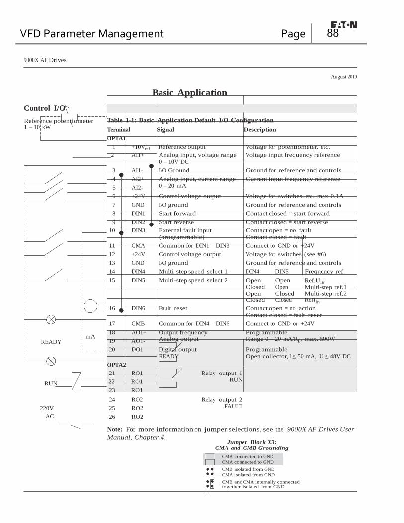
VFD Parameter Management Page 88
9000X AF Drives
August 2010
Control I/O
Reference potentiometer 1 – 10 kW
Basic Application
Table 1-1: Basic Application Default I/O Configuration
Terminal Signal Description
OPTA1
1 +10Vref Reference output Voltage for potentiometer, etc.
2 AI1+ Analog input, voltage range 0 – 10V DC
Voltage input frequency reference
3 AI1- I/O Ground Ground for reference and controls
4 AI2+ Analog input, current range Current input frequency reference
5 AI2- 0 – 20 mA
6 +24V Control voltage output Voltage for switches. etc. max 0.1A
7 GND I/O ground Ground for reference and controls
8 DIN1 Start forward Contact closed = start forward
9 DIN2 Start reverse Contact closed = start reverse
10 DIN3 External fault input (programmable)
Contact open = no fault Contact closed = fault
11 CMA Common for DIN1 – DIN3 Connect to GND or +24V
12 +24V Control voltage output Voltage for switches (see #6)
13 GND I/O ground Ground for reference and controls
14 DIN4 Multi-step speed select 1 DIN4 DIN5 Frequency ref.
15 DIN5 Multi-step speed select 2 Open Closed Open Closed
Open Open Closed Closed
Ref.Uin
Multi-step ref.1 Multi-step ref.2 RefIin
16 DIN6 Fault reset Contact open = no action
Contact closed = fault reset
17 CMB Common for DIN4 – DIN6 Connect to GND or +24V
18 AO1+ Output frequency Programmable
READY mA
19 AO1- Analog output Range 0 – 20 mA/RL, max. 500W
20 DO1 Digital output
READY
Programmable
Open collector, I ≤ 50 mA, U ≤ 48V DC
OPTA2
21 RO1 Relay output 1
RUN 22 RO1
23 RO1
RUN
24 RO2 Relay output 2
220V
AC
25 RO2
26 RO2
FAULT
Note: For more information on jumper selections, see the 9000X AF Drives User
Manual, Chapter 4. Jumper Block X3:
CMA and CMB Grounding
CMB connected to GND
CMA connected to GND CMB isolated from GND
CMA isolated from GND
CMB and CMA internally connected together, isolated from GND

VFD Parameter Management Page 89
9000X AF Drives
August 2010
Basic Application
Basic Application — Parameter Lists
On the next pages you will find the lists of parameters within the respective parameter
groups. The parameter descriptions are given in Chapter 8.
Column explanations:
Code = Location indication on the keypad; Shows the operator the present parameter
number
Parameter = Name of parameter
Min = Minimum value of parameter
Max = Maximum value of parameter
Unit = Unit of parameter value; Given if available
Default = Value preset by factory
Cust = Customer’s own setting
ID = ID number of the parameter
= Parameter value can only be changed after the drive has been stopped
= Use TTF method to program these parameters. See Page 6-3.
Monitoring Values (Control Keypad: Menu M7)
The monitoring values are the actual values of parameters and signals as well as statuses
and measurements. Monitoring values cannot be edited.
See 9000X AF Drives User Manual, Chapter 5 for more information.
Table 1-2: Monitoring Values
Code Parameter Unit ID Description
V1.1 Output frequency Hz 1 Output frequency to motor
V1.2 Frequency reference Hz 25 Frequency reference to motor control
V1.3 Motor speed rpm 2 Motor speed in rpm
V1.4 Motor current A 3 V1.5 Motor torque % 4 In % of Motor nominal torque
V1.6 Motor power % 5 Motor shaft power
V1.7 Motor voltage V 6 V1.8 DC Bus voltage V 7 V1.9 Unit temperature ∞C 8 Heatsink temperature
V1.10 Motor temperature % 9 Calculated motor temperature
V1.11 Voltage input V 13 AI1
V1.12 Current input mA 14 AI2
V1.13 DIN1, DIN2, DIN3 15 Digital input statuses
V1.14 DIN4, DIN5, DIN6 16 Digital input statuses
V1.15 DO1, RO1, RO2 17 Digital and relay output statuses
V1.16 Analog Iout mA 26 AO1
M1.17 Multimonitoring items Displays three selectable monitoring values
MN04004001E For more information visit: www.eaton.com 1-3

VFD Parameter Management Page 90
9000X AF Drives
August 2010
Basic Application
Basic Parameters (Control Keypad: M1 ➔ G1.1)
Table 1-3: Basic Parameters — G1
Code Parameter Min. Max. Unit Default Cust ID Note
P1.1 Min frequency 0.00 Par. 1.2 Hz 0.00 101 P1.2 Max frequency Par. 1.1 320.00 Hz 60.00 102 NOTE: If fmax > than the motor
synchronous speed, check suitability for motor and drive system.
P1.3 Acceleration time 1 0.1 3000.0 s 3.0 103 P1.4 Deceleration time 1 0.1 3000.0 s 3.0 104 P1.5 Current limit 0.1 x IH 2 x IH A IL 107 P1.6 Nominal voltage of the
motor 180 690 V P: 230V
P: 460V P: 575V
110 Check the rating plate of the motor.
P1.7 Nominal frequency of the motor
30.00 320.00 Hz 60.00 111 Check the rating plate of the motor.
P1.8 Nominal speed of the motor
300 20 000 rpm 1720 112 Check the rating plate of the motor. The default applies for a 4-pole motor and a nominal size frequency converter.
P1.9 Nominal current of the motor
0.1 x IH 2 x IH A IH 113 Check the rating plate of the motor.
P1.10 Preset speed 1 0.00 Par 1.1.2 Hz 10.00 105 Speeds preset by operator P1.11 Preset speed 2 0.00 Par 1.1.2 Hz 40.00 106 Speeds preset by operator P1.12 Input phase
supervision 0 3 730 0 = No action
1 = Working 2 = Fault 3 = Fault, coast
1-4 For more information visit: www.eaton.com MN04004001E

VFD Parameter Management Page 91
9000X AF Drives
August 2010
Basic Application
Keypad Control (Control Keypad: Menu M2)
The parameters for the selection of control place and direction on the keypad are listed
below. See the Keypad Control Menu in the 9000X AF Drives User Manual.
Table 1-4: Keypad Control Parameters — M2
Code Parameter Min. Max. Unit Default Cust ID Note R1.1 Keypad reference Par. 1.1 Par. 1.2 Hz 60.00 P1.2 Direction (on keypad) 0 1 0 123 Reverse request activated from the
panel R1.3 Stop button 0 1 1 114 0 = Limited function of Stop button
1 = Stop button always enabled P2.4 Operate menu hide 0 1 0 1688 0 = No
1 = Yes
System Menu (Control Keypad: Menu M5)
For parameters and functions related to the general use of the drive, such as application
and language selection, customized parameter sets or information about the hardware and
software, see Chapter 5 in the 9000X AF Drives User Manual.
Expander Boards (Control Keypad: Menu M6)
The M6 menu shows the expander and option boards attached to the control board and
board-related information. For more information, see Chapter 5 in the 9000X AF Drives
User Manual.
MN04004001E For more information visit: www.eaton.com 1-5

VFD Parameter Management Page 92
9000X AF Drives
August 2010
1-6 For more information visit: www.eaton.com MN04004001E

VFD Parameter Management Page 93
9000X AF Drives
August 2010
Chapter 2 — Standard Application
Introduction
Select the Standard Application in menu M5. See Chapter 5 of the 9000X AF Drives
User Manual.
The Standard Application is typically used in pump and fan applications and conveyors
for which the Basic Application is too limited but where no special features are needed.
● The Standard Application has the same I/O signals and the same control logic as the
Basic Application.
● Digital input DIN3 and all the outputs are freely programmable.
Additional functions:
● Programmable Start/Stop and Reverse signal logic
● Reference scaling
● One frequency limit supervision
● Second ramps and S-shape ramp programming
● Programmable start and stop functions
● DC-brake at stop
● One skip frequency area
● Programmable V/f curve and switching frequency
● Autorestart
● Motor thermal and stall protection: Programmable action; off, warning, fault
The parameters of the Standard Application are explained in Chapter 8 of this manual.
The explanations are arranged according to the individual ID number of the parameter.
MN04004001E For more information visit: www.eaton.com 2-1
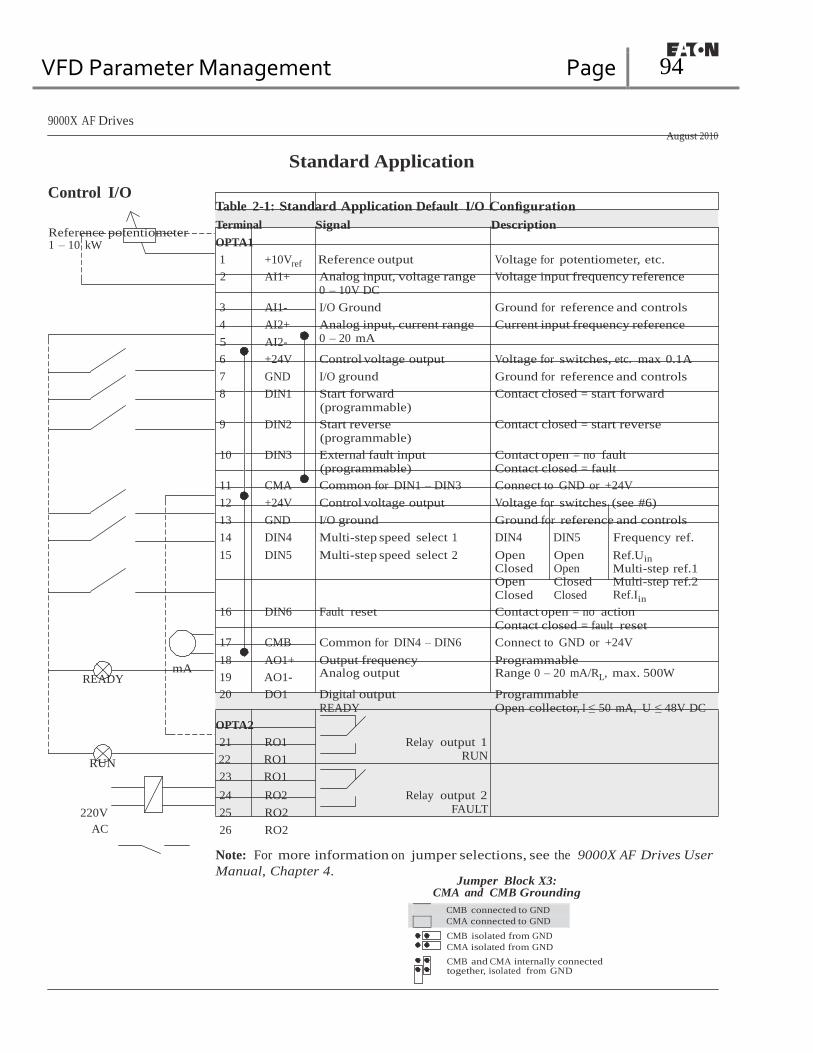
VFD Parameter Management Page 94
9000X AF Drives
August 2010
Control I/O
Reference potentiometer 1 – 10 kW
Standard Application Table 2-1: Standard Application Default I/O Configuration
Terminal Signal Description
OPTA1
1 +10Vref Reference output Voltage for potentiometer, etc.
2 AI1+ Analog input, voltage range 0 – 10V DC
Voltage input frequency reference
3 AI1- I/O Ground Ground for reference and controls
4 AI2+ Analog input, current range Current input frequency reference
5 AI2- 0 – 20 mA
6 +24V Control voltage output Voltage for switches, etc. max 0.1A
7 GND I/O ground Ground for reference and controls
8 DIN1 Start forward (programmable)
9 DIN2 Start reverse (programmable)
10 DIN3 External fault input (programmable)
Contact closed = start forward
Contact closed = start reverse
Contact open = no fault Contact closed = fault
11 CMA Common for DIN1 – DIN3 Connect to GND or +24V
12 +24V Control voltage output Voltage for switches (see #6)
13 GND I/O ground Ground for reference and controls
14 DIN4 Multi-step speed select 1 DIN4 DIN5 Frequency ref.
15 DIN5 Multi-step speed select 2 Open Closed Open Closed
Open Open Closed Closed
Ref.Uin
Multi-step ref.1 Multi-step ref.2 Ref.Iin
16 DIN6 Fault reset Contact open = no action Contact closed = fault reset
17 CMB Common for DIN4 – DIN6 Connect to GND or +24V
18 AO1+ Output frequency Programmable
READY mA
19 AO1- Analog output Range 0 – 20 mA/RL, max. 500W
20 DO1 Digital output READY
Programmable Open collector, I ≤ 50 mA, U ≤ 48V DC
OPTA2
21 RO1 Relay output 1
RUN 22 RO1
23 RO1
RUN
24 RO2 Relay output 2
220V
AC
25 RO2
26 RO2
FAULT
Note: For more information on jumper selections, see the 9000X AF Drives User
Manual, Chapter 4. Jumper Block X3:
CMA and CMB Grounding
CMB connected to GND
CMA connected to GND CMB isolated from GND
CMA isolated from GND
CMB and CMA internally connected together, isolated from GND

VFD Parameter Management Page 95
9000X AF Drives
August 2010
Standard Application
Standard Application — Parameter Lists
On the next pages you will find the lists of parameters within the respective parameter
groups. The parameter descriptions are given in Chapter 8. The descriptions are arranged
according to the ID number of the parameter.
Column explanations:
Code = Location indication on the keypad; Shows the operator the present parameter
number
Parameter = Name of parameter
Min = Minimum value of parameter
Max = Maximum value of parameter
Unit = Unit of parameter value; Given if available
Default = Value preset by factory
Cust = Customer’s own setting
ID = ID number of the parameter
= Parameter value can only be changed after the drive has been stopped.
= Use TTF method to program these parameters. See Page 6-3.
Monitoring Values (Control Keypad: Menu M7)
The monitoring values are the actual values of parameters and signals as well as statuses
and measurements. Monitoring values cannot be edited.
See 9000X AF Drives User Manual, Chapter 5 for more information.
Table 2-2: Monitoring Values
Code Parameter Unit ID Description
V1.1 Output frequency Hz 1 Output frequency to motor
V1.2 Frequency reference Hz 25 Frequency reference to motor control
V1.3 Motor speed rpm 2 Motor speed in rpm
V1.4 Motor current A 3
V1.5 Motor torque % 4 In % of the nominal motor torque
V1.6 Motor power % 5 Motor shaft power
V1.7 Motor voltage V 6
V1.8 DC Bus voltage V 7
V1.9 Unit temperature ∞C 8 Heatsink temperature
V1.10 Motor temperature % 9 Calculated motor temperature
V1.11 Analog input 1 V 13 AI1
V1.12 Analog input 2 mA 14 AI2
V1.13 DIN1, DIN2, DIN3 15 Digital input statuses
V1.14 DIN4, DIN5, DIN6 16 Digital input statuses
V1.15 DO1, RO1, RO2 17 Digital and relay output statuses
MN04004001E For more information visit: www.eaton.com 2-3

VFD Parameter Management Page 96
9000X AF Drives
August 2010
Standard Application
Table 2-2: Monitoring Values (Continued)
Code Parameter Unit ID Description
V1.16 Analog Iout mA 26 AO1
M1.17 Monitoring items Displays three selectable monitoring values
Basic Parameters (Control Keypad: Menu M1 ➔ G1.1)
Table 2-3: Basic Parameters — G1.1
Code Parameter Min. Max. Unit Default Cust ID Note P1.1.1 Min frequency 0.00 Par. 1.1.2 Hz 0.00 101 P1.1.2 Max frequency Par.
1.1.1 320.00 Hz 60.00 102 NOTE: If fmax > than the motor
synchronous speed, check suitability for motor and drive system.
P1.1.3 Acceleration time 1 0.1 3000.0 s 3.0 103 P1.1.4 Deceleration time 1 0.1 3000.0 s 3.0 104 P1.1.5 Current limit 0.1 x IH 2 x IH A IL 107 P1.1.6 Nominal voltage of the
motor 180 690 V P: 230V
P: 460V P: 575V
110
P1.1.7 Nominal frequency of the motor
30.00 320.00 Hz 60.00 111 Check the rating plate of the motor.
P1.1.8 Nominal speed of the motor
300 20 000 rpm 1720 112 The default applies for a 4-pole motor and a nominal size frequency converter.
P1.1.9 Nominal current of the motor
0.1 x IH 2 x IH A IH 113 Check the rating plate of the motor.
P1.1.10 Power Factor 0.30 1.00 0.85 120 Check the rating plate of the motor.
P1.1.11 Local Control Place
1 3 2 171 1 = I/O Terminal 2 = Keypad 3 = Fieldbus
P1.1.12 Remote Control Place
1 3 1 172 1 = I/O Terminal 2 = Keypad 3 = Fieldbus
P1.1.13 Local reference 0 3 2 173 0 = AI1 1 = AI2 2 = Keypad 3 = Fieldbus
P1.1.14 Remote reference 0 3 0 174 0 = AI1 1 = AI2 2 = Keypad 3 = Fieldbus
P1.1.15 Identification 0 2 0 631 0 = Not used 1 = V/Hz 2 = V/Hz with boost
P1.1.16 V/Hz Opt 0 1 0 109 0 = Not used 1 = Automatic torque boost
P1.1.17 Preset speed 1 0.00 Par. 1.1.2 Hz 10.00 105 Speeds preset by operator. P1.1.18 Preset speed 2 0.00 Par. 1.1.2 Hz 40.00 106
2-4 For more information visit: www.eaton.com MN04004001E

VFD Parameter Management Page 97
9000X AF Drives
August 2010
Standard Application
Input Signals (Control Keypad: Menu M1 ➔ G1.2)
Table 2-4: Input Signals — G1.2
Code Parameter Min. Max. Unit Default Cust ID Note
P1.2.1 Start/Stop logic 0 6 0 300 0 1 2 3 4 5 6
DIN1 DIN2 Start fwd Start/Stop Start/Stop Start pulse Fwd
Start /Stop Start /Stop
Start rvs Rvs/Fwd Run enable Stop pulse Rvs
Rvs/Fwd Run enable
P1.2.2 DIN3 function 0 7 1 301 0 = Not used 1 = Ext. fault. closing cont. 2 = Ext. fault. opening cont. 3 = Run enable 4 = Acc./Dec. time select. 5 = Force CP to Remote
6 = Rvs (if par. 1.2.1 = 3) P1.2.3 Current reference
offset 0 1 1 302 0 = 0 – 20mA
1 = 4 – 20mA P1.2.4 Reference scaling
minimum value 0.00 Par. 1.2.5 Hz 0.00 303 Selects the frequency that
corresponds to the min. reference signal 0.00 = No scaling
P1.2.5 Reference scaling maximum value
0.00 320.00 Hz 0.00 304 Selects the frequency that corresponds to the max. reference signal 0.00 = No scaling
P1.2.6 Reference inversion 0 1 0 305 0 = Not inverted 1 = Inverted
P1.2.7 Reference filter time 0.00 10.00 s 0.10 306 0 = No filtering P1.2.8 AI1 signal selection A.1 377 TTF programming method used.
See Page 6-3. P1.2.9 AI2 signal selection A.2 388 TTF programming method used.
See Page 6-3. Rising edge required to start. CP = control place.
Output Signals (Control Keypad: Menu M1 ➔ G1.3)
Table 2-5: Output Signals — G1.3
Code Parameter Min. Max. Unit Default Cust ID Note
P1.3.1 Analog output 1 signal selection
0 A.1 464 TTF programming method used. See Page 6-3.
P1.3.2 Analog output function
0 8 1 307 0 = Not used 1 = Output freq. (0 – fmax) 2 = Freq. reference (0 – fmax) 3 = Motor speed (0 – Motor nominal speed) 4 = Motor current (0 – InMotor) 5 = Motor torque (0 – TnMotor) 6 = Motor power (0 – PnMotor) 7 = Motor voltage (0 – UnMotor) 8 = DC-Bus volt (0 – 1000V)
P1.3.3 Analog output filter time
0.00 10.00 s 1.00 308 0 = No filtering

VFD Parameter Management Page 98
9000X AF Drives
August 2010
Standard Application
Table 2-5: Output Signals — G1.3 (Continued)
Code Parameter Min. Max. Unit Default Cust ID Note P1.3.4 Analog output
inversion 0 1 0 309 0 = Not inverted
1 = Inverted P1.3.5 Analog output
minimum 0 1 0 310 0 = 0 mA
1 = 4 mA P1.3.6 Analog output scale 10 1000 % 100 311 P1.3.7 Digital output 1
function 0 16 1 312 0 = Not used
1 = Ready 2 = Run 3 = Fault 4 = Fault inverted 5 = FC overheat warning 6 = Ext. fault or warning 7 = Ref. fault or warning 8 = Warning 9 = Reversed 10 = Preset speed 1 11 = At speed 12 = Mot. regulator active 13 = OP freq. limit 1 superv. 14 = Remote Control Active 15 = Thermistor fault/warng 16 = Fieldbus input data
P1.3.8 Relay output 1 function
0 16 2 313 Same as parameter 1.3.7
P1.3.9 Relay output 2 function
0 16 3 314 Same as parameter 1.3.7
P1.3.10 Output frequency limit 1 supervision
0 2 0 315 0 = No limit 1 = Low limit supervision 2 = High limit supervision
P1.3.11 Output frequency limit 1; Supervised value
0.00 320.00 Hz 0.00 316
P1.3.12 Analog output 2 signal selection
0 0.1 471 TTF programming method used. See Page 6-3.
P1.3.13 Analog output 2 function
0 8 4 472 Same as parameter 1.3.2
P1.3.14 Analog output 2 filter time
0.00 10.00 s 1.00 473 0 = No filtering
P1.3.15 Analog output 2 inversion
0 1 0 474 0 = Not inverted 1 = Inverted
P1.3.16 Analog output 2 minimum
0 1 0 475 0 = 0 mA 1 = 4 mA
P1.3.17 Analog output 2 scaling
10 1000 % 100 476
2-6 For more information visit: www.eaton.com MN04004001E

VFD Parameter Management Page 99
9000X AF Drives
August 2010
Standard Application
Drive Control Parameters (Control Keypad: Menu M1 ➔ G1.4)
Table 2-6: Drive Control Parameters — G1.4
Code Parameter Min. Max. Unit Default Cust ID Note P1.4.1 Ramp 1 shape 0.0 10.0 s 0.0 500 0 = Linear
>0 = S-curve ramp time P1.4.2 Ramp 2 shape 0.0 10.0 s 0.0 501 0 = Linear
>0 = S-curve ramp time P1.4.3 Acceleration time 2 0.1 3000.0 s 10.0 502 P1.4.4 Deceleration time 2 0.1 3000.0 s 10.0 503 P1.4.5 Brake chopper 0 4 0 504 0 = Disabled
1 = Used when running 2 = External brake chopper 3 = Used when stopped/running 4 = Used when running (no testing)
P1.4.6 Start function 0 1 0 505 0 = Ramp 1 = Flying start
P1.4.7 Stop function 0 3 1 506 0 = Coasting 1 = Ramp 2 = Ramp+Run enable coast 3 = Coast+Run enable ramp
P1.4.8 DC braking current 0.00 IL A 0.7 x IH 507 P1.4.9 DC braking time at
stop 0.00 600.00 s 0.00 508 0 = DC brake is off at stop
P1.4.10 Frequency to start DC braking during ramp stop
0.10 10.00 Hz 1.50 515
P1.4.11 DC braking time at start
0.00 600.00 s 0.00 516 0 = DC brake is off at start
P1.4.12 Flux brake 0 1 0 520 0 = Off 1 = On
P1.4.13 Flux braking current 0.1 x IH IL A IH 519
Skip Frequency Parameters (Control Keypad: Menu M1 ➔ G1.5)
Table 2-7: Skip Frequency Parameters — G1.5
Code Parameter Min. Max. Unit Default Cust ID Note P1.5.1 Skip frequency
range 1 low limit 0.00 Par. 1.5.2 Hz 0.00 509
P1.5.2 Skip frequency range 1 high limit
0.00 Par. 1.1.2 Hz 0.0 510 0 = Skip frequency range 1 not used
P1.5.3 Skip frequency acc./dec. ramp
0.1 10.0 1.0 518
MN04004001E For more information visit: www.eaton.com 2-7
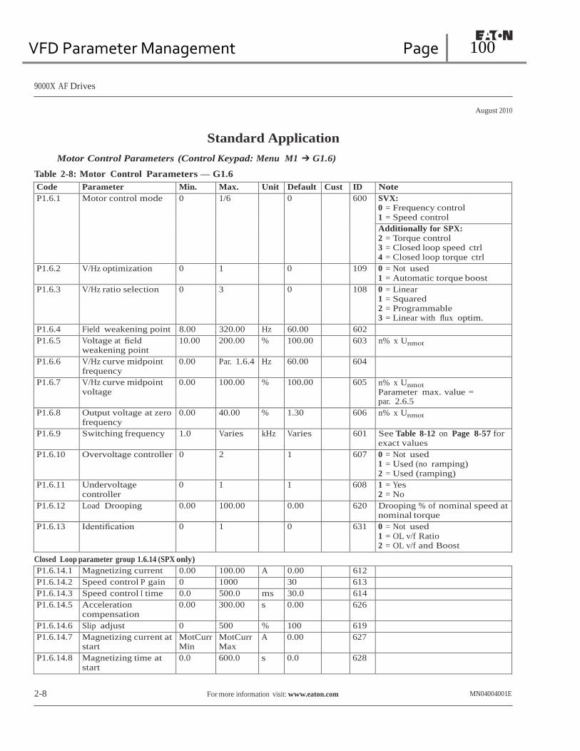
VFD Parameter Management Page 100
9000X AF Drives
August 2010
Standard Application
Motor Control Parameters (Control Keypad: Menu M1 ➔ G1.6)
Table 2-8: Motor Control Parameters — G1.6
Code Parameter Min. Max. Unit Default Cust ID Note P1.6.1 Motor control mode 0 1/6 0 600 SVX:
0 = Frequency control 1 = Speed control Additionally for SPX: 2 = Torque control 3 = Closed loop speed ctrl 4 = Closed loop torque ctrl
P1.6.2 V/Hz optimization 0 1 0 109 0 = Not used 1 = Automatic torque boost
P1.6.3 V/Hz ratio selection 0 3 0 108 0 = Linear 1 = Squared 2 = Programmable 3 = Linear with flux optim.
P1.6.4 Field weakening point 8.00 320.00 Hz 60.00 602 P1.6.5 Voltage at field
weakening point 10.00 200.00 % 100.00 603 n% x Unmot
P1.6.6 V/Hz curve midpoint frequency
0.00 Par. 1.6.4 Hz 60.00 604
P1.6.7 V/Hz curve midpoint voltage
0.00 100.00 % 100.00 605 n% x Unmot
Parameter max. value = par. 2.6.5
P1.6.8 Output voltage at zero frequency
0.00 40.00 % 1.30 606 n% x Unmot
P1.6.9 Switching frequency 1.0 Varies kHz Varies 601 See Table 8-12 on Page 8-57 for exact values
P1.6.10 Overvoltage controller 0 2 1 607 0 = Not used 1 = Used (no ramping) 2 = Used (ramping)
P1.6.11 Undervoltage controller
0 1 1 608 1 = Yes 2 = No
P1.6.12 Load Drooping 0.00 100.00 0.00 620 Drooping % of nominal speed at nominal torque
P1.6.13 Identification 0 1 0 631 0 = Not used 1 = OL v/f Ratio 2 = OL v/f and Boost
Closed Loop parameter group 1.6.14 (SPX only)
P1.6.14.1 Magnetizing current 0.00 100.00 A 0.00 612 P1.6.14.2 Speed control P gain 0 1000 30 613 P1.6.14.3 Speed control I time 0.0 500.0 ms 30.0 614 P1.6.14.5 Acceleration
compensation 0.00 300.00 s 0.00 626
P1.6.14.6 Slip adjust 0 500 % 100 619 P1.6.14.7 Magnetizing current at
start MotCurr Min
MotCurr Max
A 0.00 627
P1.6.14.8 Magnetizing time at start
0.0 600.0 s 0.0 628
2-8 For more information visit: www.eaton.com MN04004001E

VFD Parameter Management Page 101
9000X AF Drives
August 2010
Standard Application
Motor Control Parameters — G1.6
Code Parameter Min. Max. Unit Default Cust ID Note Closed Loop parameter group 1.6.14 (SPX only) (Continued)
P1.6.14.9 0-speed time at start 0 32000 ms 100 615 P1.6.14.10 0-speed time at stop 0 32000 ms 100 616 P1.6.14.11 Start-up torque 0 3 0 621 0 = Not used
1 = Torque memory 2 = Torque reference 3 = Start-up torque fwd/rev
P1.6.14.12 Start-up torque FWD -300.0 300.0 s 0.0 633 P1.6.14.13 Start-up torque REV -300.0 300.0 s 0.0 634 P1.6.14.15 Encoder filter time 0 1000 ms 0 618 P1.6.14.17 Current control
P gain 0.00 100.00 % 40.00 617
Protections (Control Keypad: Menu M1 ➔ G1.7)
Table 2-9: Protections — G1.7
Code Parameter Min. Max. Unit Default Cust ID Note P1.7.1 Response to
reference fault 0 6 6 700 0 = No response
1 = Warning 2 = Warning+Previous Freq. 3 = Wrng+PresetFreq 1.7.2 4 = Fault.stop acc. to 1.4.7 5 = Fault.stop by coasting 6 = Fault, Restart
P1.7.2 Reference fault frequency
0.00 Par. 1.1.2 Hz 0.00 728
P1.7.3 Response to external fault
0 3 2 701 0 = No response 1 = Warning 2 = Fault.stop acc. to 1.4.7 3 = Fault.stop by coasting
P1.7.4 Input phase supervision
0 3 3 730
P1.7.5 Response to undervoltage fault
1 3 0 727
P1.7.6 Output phase supervision
0 3 2 702
P1.7.7 Earth fault protection 0 3 2 703 P1.7.8 Thermal protection of
the motor 0 3 2 704
P1.7.9 Motor ambient temperature factor
-100.0 100.0 % 0.0 705
P1.7.10 Motor cooling factor at zero speed
0.0 150.0 % 40.0 706
P1.7.11 Motor thermal time constant
1 200 min 45 707
P1.7.12 Motor duty cycle 0 100 % 100 708 P1.7.13 Stall protection 0 3 0 709 0 = No response
1 = Warning 2 = Fault.stop acc. to 1.4.7 3 = Fault.stop by coasting
MN04004001E For more information visit: www.eaton.com 2-9

VFD Parameter Management Page 102
9000X AF Drives
August 2010
Standard Application
Table 2-9: Protections — G1.7 (Continued)
Code Parameter Min. Max. Unit Default Cust ID Note P1.7.14 Stall current 0.1 InMotor
x 2 A IL 710
P1.7.15 Stall time limit 1.00 120.00 s 15.00 711 P1.7.16 Stall frequency limit 1.0 Par.
1.1.2 Hz 25.0 712
P1.7.17 Underload protection 0 3 0 713 0 = No response 1 = Warning 2 = Fault.stop acc. to 1.4.7 3 = Fault.stop by coasting
P1.7.18 Field weakening area load
10 150 % 50 714
P1.7.19 Zero frequency load 5.0 150.0 % 10.0 715 P1.7.20 Underload protection
time limit 2 600 s 20 716
P1.7.21 Response to thermistor fault
0 3 2 732 0 = No response 1 = Warning 2 = Fault.stop acc. to 1.4.7 3 = Fault.stop by coasting
P1.7.22 Response to fieldbus fault
0 3 2 733 See P1.7.21
P1.7.23 Response to slot fault 0 3 2 734 See P1.7.21 P1.7.24 FB MCW Bit 15 0 2 0 771 0 = No action
1 = Fault low 2 = Fault high
Autorestart Parameters (Control Keypad: Menu M1 ➔ G1.8)
Table 2-10: Autorestart Parameters — G1.8
Code Parameter Min. Max. Unit Default Cust ID Note P1.8.1 Wait time 0.10 10.00 s 0.50 717 P1.8.2 Trial time 0.00 60.00 s 30.00 718 P1.8.3 Start function 0 2 0 719 0 = Ramp
1 = Flying start 2 = According to par. 1.4.6
P1.8.4 Number of tries after undervoltage trip
0 10 0 720
P1.8.5 Number of tries after overvoltage trip
0 10 0 721
P1.8.6 Number of tries after overcurrent trip
0 3 0 722
P1.8.7 Number of tries after reference trip
0 10 0 723
P1.8.8 Number of tries after motor temperature fault trip
0 10 0 726
P1.8.9 Number of tries after external fault trip
0 10 0 725
P1.8.10 Number of tries after underload fault trip
0 10 0 738
2-10 For more information visit: www.eaton.com MN04004001E

VFD Parameter Management Page 103
9000X AF Drives
August 2010
Standard Application
Keypad Control (Control Keypad: Menu M2)
The parameters for the selection of control place and direction on the keypad are listed
below. See the Keypad control menu in the 9000X AF Drives User Manual.
Table 2-11: Keypad Control Parameters — M2
Code Parameter Min. Max. Unit Default Cust ID Note P2.1 Control place 0 3 0 1685 0 = Keypad L/R
1 = Local 2 = Remote 3 = I/O force
R2.1 Keypad reference Par. 1.1.1 Par. 1.1.2 Hz P2.3 Direction (on keypad) 0 1 0 123 0 = Forward
1 = Reverse P2.4 Stop button 0 1 1 114 0 = Limited function of Stop button
1 = Stop button always enabled P2.5 Operate menu hide 0 1 0 1688 0 = No
1 = Yes
System Menu (Control Keypad: Menu M5)
For parameters and functions related to the general use of the drive, such as application
and language selection, customized parameter sets or information about the hardware and
software, see Chapter 5 in the 9000X AF Drives User Manual.
Expander Boards (Control Keypad: Menu M6)
The M6 menu shows the expander and option boards attached to the control board and
board-related information. For more information, see Chapter 5 in the 9000X AF Drives
User Manual.
MN04004001E For more information visit: www.eaton.com 2-11

VFD Parameter Management Page 104
9000X AF Drives
August 2010
2-12 For more information visit: www.eaton.com MN04004001E

VFD Parameter Management Page 105
9000X AF Drives
August 2010
Chapter 3 — Local/Remote Control Application
Introduction
Select the Local/Remote Control Application in menu M5. See Chapter 5 of the 9000X AF
Drives User Manual.
● The Local/Remote Application utilizes digital input DIN6 to select between Local and
Remote control. For each control location, the frequency can be selected from either
the keypad, I/O terminals, or fieldbus.
● All outputs are freely programmable.
Additional functions:
● Programmable Start/Stop and Reverse signal logic
● Second I/O programmable stay/stop and reverse signal logic
● Reference scaling
● One frequency limit supervision
● Second ramps and S-shape ramp programming
● Programmable start and stop functions
● DC-brake at stop
● One skip frequency area
● Programmable v/f curve and switching frequency
● Autorestart
● Motor thermal and stall protection: Programmable action; off, warning, fault
The parameters of the Local/Remote Control Application are explained in Chapter 8 of
this manual. The explanations are arranged according to the individual ID number of
the parameter.
MN04004001E For more information visit: www.eaton.com 3-1
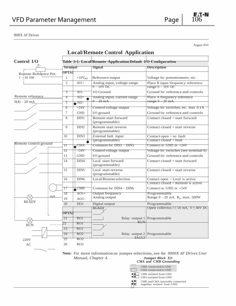
VFD Parameter Management Page 106
9000X AF Drives
August 2010
Control I/O
Remote Reference Pot. 1 – 10 kW
Local/Remote Control Application Table 3-1: Local/Remote Application Default I/O Configuration
Terminal Signal Description
OPTA1
1 +10Vref Reference output Voltage for potentiometer, etc.
2 AI1+ Analog input, voltage range 0 – 10V DC
Place B input frequency reference range 0 – 10V DC
3 AI1- I/O Ground Ground for reference and controls
Remote reference 4 AI2+ Analog input, current range Place A frequency reference
0(4) – 20 mA 5 AI2- 0 – 20 mA range 0 – 20 mA
6 +24V Control voltage output Voltage for switches, etc. max 0.1A
7 GND I/O ground Ground for reference and controls
8 DIN1 Remote start forward
(programmable)
9 DIN2 Remote start reverse (programmable)
10 DIN3 External fault input
(programmable)
Contact closed = start forward
Contact closed = start reverse
Contact open = no fault
Contact closed = fault
Remote control ground
11 CMA Common for DIN1 – DIN3 Connect to GND or +24V
12 +24V Control voltage output Voltage for switches (see terminal 6)
13 GND I/O ground Ground for reference and controls
14 DIN4 Local start forward
(programmable)
15 DIN5 Local start reverse (programmable)
Contact closed = start forward
Contact closed = start reverse
16 DIN6 Local/Remote selection Contact open = Local is active
Contact closed = Remote is active
17 CMB Common for DIN4 – DIN6 Connect to GND or +24V
18 AO1+ Output frequency Programmable mA
19 AO1- Analog output Range 0 – 20 mA, RL, max. 500W
READY 20 DO1 Digital output
READY
Programmable
Open collector, I ≤ 50 mA, V ≤ 48V DC
OPTA2
21 RO1 Relay output 1 Programmable
RUN 22 RO1
23 RO1
RUN
24 RO2 Relay output 2 Programmable
220V
AC
25 RO2
26 RO2
FAULT
Note: For more information on jumper selections, see the 9000X AF Drives User
Manual, Chapter 4. Jumper Block X3: CMA and CMB Grounding
CMB connected to GND
CMA connected to GND CMB isolated from GND
CMA isolated from GND
CMB and CMA internally connected together, isolated from GND

VFD Parameter Management Page 107
9000X AF Drives
August 2010
Local/Remote Control Application
Local/Remote Control Application — Parameter Lists
On the next pages you will find the lists of parameters within the respective parameter
groups. The parameter descriptions are given in Chapter 8.
Column explanations:
Code = Location indication on the keypad; Shows the operator the present parameter
number
Parameter = Name of parameter
Min = Minimum value of parameter
Max = Maximum value of parameter
Unit = Unit of parameter value; Given if available
Default = Value preset by factory
Cust = Customer’s own setting
ID = ID number of the parameter
= Parameter value can only be changed after the drive has been stopped.
= Use TTF method to program these parameters. See Page 6-3.
Monitoring Values (Control Keypad: Menu M7)
The monitoring values are the actual values of parameters and signals as well as statuses
and measurements. Monitoring values cannot be edited.
See 9000X AF Drives User Manual, Chapter 5 for more information.
Table 3-2: Monitoring Values
Code Parameter Unit ID Description
V1.1 Output frequency Hz 1 Output frequency to motor V1.2 Frequency reference Hz 25 Frequency reference to motor control V1.3 Motor speed rpm 2 Motor speed in rpm V1.4 Motor current A 3 V1.5 Motor torque % 4 In % of motor nominal torque V1.6 Motor power % 5 Motor shaft power V1.7 Motor voltage V 6 V1.8 DC Bus voltage V 7 V1.9 Unit temperature °C 8 Heatsink temperature V1.10 Motor temperature % 9 Calculated motor temperature V1.11 Analog input 1 V 13 AI1 V1.12 Analog input 2 mA 14 AI2 V1.13 DIN1, DIN2, DIN3 15 Digital input statuses V1.14 DIN4, DIN5, DIN6 16 Digital input statuses V1.15 DO1, RO1, RO2 17 Digital and relay output statuses V1.16 Analog Iout mA 26 AO1 M1.17 Multimonitoring items Displays three selectable monitoring
values

VFD Parameter Management Page 108
9000X AF Drives
August 2010
Local/Remote Control Application
Basic Parameters (Control Keypad: Menu M1 ➔ G1.1)
Table 3-3: Basic Parameters — G1.1
Code Parameter Min. Max. Unit Default Cust ID Note P1.1.1 Min frequency 0.00 Par. 1.1.2 Hz 0.00 101 P1.1.2 Max frequency Par. 1.1.1 320.00 Hz 60.00 102 NOTE: If fmax > than the
motor synchronous speed, check suitability for motor and drive system.
P1.1.3 Acceleration time 1 0.1 3000.0 s 3.0 103 P1.1.4 Deceleration time 1 0.1 3000.0 s 3.0 104 P1.1.5 Current limit 0.1 x IH 2 x IH A IL 107 P1.1.6 Nominal voltage of the
motor 180 690 V P: 230V
P: 460V P: 575V
110
P1.1.7 Nominal frequency of the motor
30.00 320.00 Hz 60.00 111 Check the rating plate of the motor.
P1.1.8 Nominal speed of the motor
300 20 000 rpm 1720 112 The default applies for a 4-pole motor and a nominal size frequency converter.
P1.1.9 Nominal current of the motor
0.1 x IH 2 x IH A IH 113 Check the rating plate of the motor.
P1.1.10 Power Factor 0.30 1.00 0.85 120 Check the rating plate of the motor.
P1.1.11 Local Control Place 1 4 2 171 1 = I/O Terminal 2 = Keypad 3 = Fieldbus 4 = I/O Terminal B
P1.1.12 Remote Control Place 1 4 1 172 1 = I/O Terminal 2 = Keypad 3 = Fieldbus 4 = I/O Terminal B
P1.1.13 Local reference 0 4 2 173 0 = AI1 1 = AI2 2 = Keypad 3 = Fieldbus 4 = Motor potentiometer
P1.1.14 Remote reference 0 3 0 174 0 = AI1 1 = AI2 2 = Keypad 3 = Fieldbus
P.1.1.15 Identification 0 2 0 631 0 = Not used 1 = V/Hz 2 = V/Hz with boost
P.1.1.16 V/Hz Opt 0 1 0 109 0 = Not used 1 = Automatic torque boost
P1.1.17 Jogging speed reference
0.00 Par. 1.1.2 Hz 0.00 124
3-4 For more information visit: www.eaton.com MN04004001E
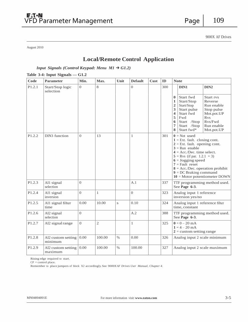
VFD Parameter Management Page 109
9000X AF Drives
August 2010
Local/Remote Control Application
Input Signals (Control Keypad: Menu M1 ➔ G1.2)
Table 3-4: Input Signals — G1.2
Code Parameter Min. Max. Unit Default Cust ID Note
P1.2.1 Start/Stop logic selection
0 8 0 300
0 1 2 3 4 5 6 7 8
DIN1 DIN2
Start fwd Start/Stop Start/Stop Start pulse Start fwd Fwd
Start /Stop Start /Stop Start fwd*
Start rvs Reverse Run enable Stop pulse Mot.pot.UP Rvs
Rvs/Fwd Run enable Mot.pot.UP
P1.2.2 DIN3 function 0 13 1 301 0 = Not used 1 = Ext. fault. closing cont. 2 = Ext. fault. opening cont. 3 = Run enable 4 = Acc./Dec. time select. 5 = Rvs (if par. 1.2.1 = 3) 6 = Jogging speed 7 = Fault reset 8 = Acc./Dec. operation prohibit 9 = DC Braking command 10 = Motor potentiometer DOWN
P1.2.3 AI1 signal selection
0 A.1 337 TTF programming method used. See Page 6-3.
P1.2.4 AI1 signal inversion
0 1 0 323 Analog input 1 reference inversion yes/no
P1.2.5 AI1 signal filter time
0.00 10.00 s 0.10 324 Analog input 1 reference filter time, constant
P1.2.6 AI2 signal selection
0 A.2 388 TTF programming method used. See Page 6-3.
P1.2.7 AI2 signal range 0 2 1 325 0 = 0 – 20 mA
1 = 4 – 20 mA
2 = custom setting range
P1.2.8 AI2 custom setting minimum
0.00 100.00 % 0.00 326 Analog input 2 scale minimum
P1.2.9 AI2 custom setting maximum
0.00 100.00 % 100.00 327 Analog input 2 scale maximum
Rising edge required to start. CP = control place. Remember to place jumpers of block X2 accordingly. See 9000X AF Drives User Manual, Chapter 4.
MN04004001E For more information visit: www.eaton.com 3-5

VFD Parameter Management Page 110
9000X AF Drives
August 2010
Local/Remote Control Application
Table 3-4: Input Signals — G1.2 (Continued)
Code Parameter Min. Max. Unit Default Cust ID Note
P1.2.10 AI2 signal inversion 0 1 0 328 Analog input 2 reference inversion yes/no
P1.2.11 AI2 signal filter time 0.00 10.00 s 0.10 329 Analog input 2 reference filter time, constant
P1.2.12
Place B Start/Stop logic selection
0
6
0
363
DIN4 DIN5
0 1 2 3 4 5 6
Start fwd Start/Stop Start/Stop Start pulse Fwd
Start /Stop Start /Stop
Start rvs Rvs/Fwd Run enable Stop pulse Rvs
Rvs/Fwd Run enable
P1.2.13 Reference scaling minimum value
0.00 par. 1.2.17 Hz 0.00 303 Selects the frequency that corresponds to the min. reference signal
P1.2.14 Reference scaling maximum value
0.00 320.00 Hz 0.00 304 Selects the frequency that corresponds to the max. reference signal 0.00 = No scaling >0 = scaled max. value
P1.2.15 Motor potentiometer ramp time
0.1 2000.0 Hz/s 10.0 331
P1.2.16 Motor potentiometer frequency reference memory reset
0 2 1 367 0 = No reset
1 = Reset if stopped or powered down 2 = Reset if powered down
P1.2.17 Start pulse memory 0 1 0 498 0 = Run state not copied
1 = Run state copied
Rising edge required to start.
3-6 For more information visit: www.eaton.com MN04004001E

VFD Parameter Management Page 111
9000X AF DrivesAugust 2010
Local/Remote Control Application
Output Signals (Control Keypad: Menu M1 ➔ G1.3)
Table 3-5: Output Signals — G1.3
Code Parameter Min. Max. Unit Default Cust ID Note
P1.3.1 AO1 signal selection
0 A.1 464 TTF programming method used. See Page 6-3.
P1.3.2 Analog output function
0 8 1 307 0 = Not used
1 = Output freq. (0 – fmax) 2 = Freq. reference (0 – fmax) 3 = Motor speed (0 – Motor nominal speed) 4 = Motor current (0 – InMotor) 5 = Motor torque (0 – TnMotor) 6 = Motor power (0 – PnMotor) 7 = Motor voltage (0 – UnMotor) 8 = DC-bus volt (0 – 1000V)
P1.3.3 Analog output filter time
0.00 10.00 s 1.00 308 0 = No filtering
P1.3.4 Analog output inversion
0 1 0 309 0 = Not inverted
1 = Inverted P1.3.5 Analog output
minimum 0 1 0 310 0 = 0 mA
1 = 4 mA P1.3.6 Analog output
scale 10 1000 % 100 311
P1.3.7 Digital output 1 function
0 22 1 312 0 = Not used
1 = Ready 2 = Run 3 = Fault 4 = Fault inverted 5 = FC overheat warning 6 = Ext. fault or warning 7 = Ref. fault or warning 8 = Warning 9 = Reversed 10 = Jogging spd selected 11 = At speed 12 = Mot. regulator active 13 = OP freq.limit superv. 1 14 = OP freq.limit superv. 2 15 = Torque limit superv. 16 = Ref. limit superv. 17 = Ext. brake control 18 = Remote control active 19 = FC temp. limit superv. 20 = Unrequested rotation direction 21 = Ext. brake control inverted 22 = Thermistor fault/warn.
P1.3.8 Relay output 1 function
0 22 2 313 Same as parameter 1.3.7
P1.3.9 Relay output 2 function
0 22 3 314 Same as parameter 1.3.7
P1.3.10 Output frequency limit 1 supervision
0 2 0 315 0 = No limit 1 = Low limit supervision 2 = High limit supervision
MN04004001E For more information visit: www.eaton.com 3-7

VFD Parameter Management Page 112
9000X AF Drives
August 2010
Local/Remote Control Application
Output Signals — G1.3 (Continued)
Code Parameter Min. Max. Unit Default Cust ID Note
P1.3.11 Output frequency limit 1; Supervision value
0.00 320.00 Hz 0.00 316
P1.3.12 Output frequency limit 2 supervision
0 2 0 346 0 = No limit 1 = Low limit supervision 2 = High limit supervision
P1.3.13 Output frequency limit 2; Supervision value
0.00 320.00 Hz 0.00 347
P1.3.14 Torque limit supervision function
0 2 0 348 0 = No
1 = Low limit 2 = High limit
P1.3.15 Torque limit supervision value
0.0 200.0 % 0.0 349
P1.3.16 Reference limit supervision function
0 2 0 350 0 = No
1 = Low limit 2 = High limit
P1.3.17 Reference limit supervision value
0.0 100.0 % 0.0 351
P1.3.18 External brake Off- delay
0.0 100.0 s 0.5 352
P1.3.19 External brake On- delay
0.0 100.0 s 1.5 353
P1.3.20 Frequency converter temperature limit supervision
0 2 0 354 0 = No 1 = Low limit 2 = High limit
P1.3.21 Frequency converter temperature limit value
-10 75 °C 0 355
P1.3.22 Analog output 2 signal selection
0 0.1 471 TTF programming method used. See Page 6-3.
P1.3.23 Analog output 2 function
0 8 4 472 Same as parameter 1.3.2
P1.3.24 Analog output 2 filter time
0.00 10.00 s 1.00 473 0 = No filtering
P1.3.25 Analog output 2 inversion
0 1 0 474 0 = Not inverted 1 = Inverted
P1.3.26 Analog output 2 minimum
0 1 0 475 0 = 0 mA
1 = 4 mA
P1.3.27 Analog output 2 scaling
10 1000 % 100 476
3-8 For more information visit: www.eaton.com MN04004001E

VFD Parameter Management Page 113
9000X AF Drives
August 2010
Local/Remote Control Application
Drive Control Parameters (Control Keypad: Menu M1 ➔ G1.4)
Table 3-6: Drive Control Parameters — G1.4
Code Parameter Min. Max. Unit Default Cust ID Note
P1.4.1 Ramp 1 shape 0.0 10.0 s 0.0 500 0 = Linear >0 = S-curve ramp time
P1.4.2 Ramp 2 shape 0.0 10.0 s 0.0 501 0 = Linear >0 = S-curve ramp time
P1.4.3 Acceleration time 2
0.1 3000.0 s 10.0 502
P1.4.4 Deceleration time 2
0.1 3000.0 s 10.0 503
P1.4.5 Brake chopper 0 4 0 504 0 = Disabled 1 = Used when running 2 = External brake chopper 3 = Used when stopped/ running 4 = Used when running (no testing)
P1.4.6 Start function 0 1 0 505 0 = Ramp 1 = Flying start
P1.4.7 Stop function 0 3 1 506 0 = Coasting 1 = Ramp 2 = Ramp+Run enable coast 3 = Coast+Run enable ramp
P1.4.8 DC braking current
0.0 x IH 2 x IH A 0.7 x IH 507
P1.4.9 DC braking time at stop
0.00 600.00 s 0.00 508 0 = DC brake is off at stop
P1.4.10 Frequency to start DC braking during ramp stop
0.10 10.00 Hz 1.50 515
P1.4.11 DC braking time at start
0.00 600.00 s 0.00 516 0 = DC brake is off at start
P1.4.12 Flux brake 0 1 0 520 0 = Off 1 = On
P1.4.13 Flux braking current
0.1 x IH 2 x IH A IH 519
MN04004001E For more information visit: www.eaton.com 3-9

VFD Parameter Management Page 114
9000X AF Drives
August 2010
Local/Remote Control Application
Skip Frequency Parameters (Control Keypad: Menu M1 ➔ G1.5)
Table 3-7: Skip Frequency Parameters — G1.5
Code Parameter Min. Max. Unit Default Cust ID Note
P1.5.1 Skip frequency range 1 low limit
0.00 par. 1.5.2 Hz 0.00 509
P1.5.2 Skip frequency range 1 high limit
0.00 par. 1.1.2 Hz 0.0 510 0 = Skip frequency range 1 not used
P1.5.3 Skip frequency range 2 low limit
0.00 par. 1.5.2 Hz 0.00 511
P1.5.4 Skip frequency range 2 high limit
0.00 par. 1.1.2 Hz 0.0 512 0 = Skip frequency range 2 not used
P1.5.5 Skip frequency range 3 low limit
0.00 par. 1.5.2 Hz 0.00 513
P1.5.6 Skip frequency range 3 high limit
0.00 par. 1.1.2 Hz 0.0 514 0 = Skip frequency range 3 not used
P1.5.7 Skip frequency acc./dec. ramp
0.1 10.0 1.0 518
Motor Control Parameters (Control Keypad: Menu M1 ➔ G1.6)
Table 3-8: Motor Control Parameters — G1.6
Code Parameter Min. Max. Unit Default Cust ID Note
P1.6.1 Motor control mode
0 1/6 0 600 0 = Frequency control 1 = Speed control
Additionally for SPX: 2 = Torque control 3 = Closed loop speed ctrl 4 = Closed loop torque ctrl
P1.6.2 V/Hz optimization
0 1 0 109 0 = Not used
1 = Automatic torque boost
P1.6.3 V/Hz ratio selection
0 3 0 108 0 = Linear
1 = Squared 2 = Programmable 3 = Linear with flux optim.
P1.6.4 Field weakening point
8.00 320.00 Hz 60.00 602
P1.6.5 Voltage at field weakening point
10.00 200.00 % 100.00 603 n% x Unmot
P1.6.6 V/Hz curve midpoint frequency
0.00 Par. 1.6.4 Hz 60.00 604
P1.6.7 V/Hz curve midpoint voltage
0.00 100.00 % 100.00 605 n% x Unmot
Parameter max. value = par. 1.6.5
3-10 For more information visit: www.eaton.com MN04004001E

VFD Parameter Management Page 115
9000X AF Drives
August 2010
Local/Remote Control Application
Table 3-8: Motor Control Parameters — G1.6 (Continued)
Code Parameter Min. Max. Unit Default Cust ID Note
P1.6.8 Output voltage at zero frequency
0.00 40.00 % 1.30 606 n% x Unmot
P1.6.9 Switching frequency
1.0 Varies kHz Varies 601 See Table 8-12 on Page 8-57 for exact values
P1.6.10 Overvoltage controller
0 2 1 607 0 = Not used
1 = Used (no ramping) 2 = Used (ramping)
P1.6.11 Undervoltage
controller 0 1 1 608 0 = Not used
1 = Used
P1.6.12 Load Drooping 0.00 100.00 0.00 620 Drooping % of nominal speed at nominal torque
P1.6.13 Identification 0 1 0 631 0 = Not used 1 = V/Hz 2 = V/Hz w/boost
Closed Loop parameter group 1.6.14 (SPX only)
P1.6.14.1 Magnetizing current
0.00 100.00 A 0.00 612
P1.6.14.2 Speed control P gain
0 1000 30 613
P1.6.14.3 Speed control I time
0.0 500.0 ms 30.0 614
P1.6.14.5 Acceleration compensation
0.00 300.00 s 0.00 626
P1.6.14.6 Slip adjust 0 500 % 100 619 P1.6.14.7 Magnetizing
current at start MotCurr Min
MotCurr Max
A 0.00 627
P1.6.14.8 Magnetizing time at start
0.0 600.0 s 0.0 628
P1.6.14.9 0-speed time at start
0 32000 ms 100 615
P1.6.14.10 0-speed time at stop
0 32000 ms 100 616
P1.6.14.11 Start-up torque 0 3 0 621 0 = Not used 1 = Torque memory 2 = Torque reference 3 = Start-up torque fwd/rev
P1.6.14.12 Start-up torque FWD
-300.0 300.0 s 0.0 633
P1.6.14.13 Start-up torque REV
-300.0 300.0 s 0.0 634
P1.6.14.15 Encoder filter time
0 1000 ms 0 618
P1.6.14.17 Current control P gain
0.00 100.00 % 40.00 617
MN04004001E For more information visit: www.eaton.com 3-11

VFD Parameter Management Page 116
9000X AF Drives
August 2010
Local/Remote Control Application
Protections (Control Keypad: Menu M1 ➔ G1.7)
Table 3-9: Protections — G1.7
Code Parameter Min. Max. Unit Default Cust ID Note
P1.7.1 Response to reference fault
0 5 0 700 0 = No response 1 = Warning 2 = Warning+Previous Freq. 3 = Wrng+PresetFreq 1.7.2 4 = Fault.stop acc. to 1.4.7 5 = Fault.stop by coasting
P1.7.2 4mA reference fault frequency
0.00 Par. 1.1.2 Hz 0.00 728
P1.7.3 Response to external fault
0 3 2 701 0 = No response 1 = Warning 2 = Fault.stop acc. to 1.4.7 3 = Fault.stop by coasting
P1.7.4 Input phase supervision
0 3 3 730
P1.7.5 Response to undervoltage fault
1 3 0 727
P1.7.6 Output phase supervision
0 3 2 702
P1.7.7 Earth fault protection
0 3 2 703
P1.7.8 Thermal protection of the motor
0 3 2 704
P1.7.9 Motor ambient temperature factor
-100.0 100.0 % 0.0 705
P1.7.10 Motor cooling factor at zero speed
0.0 150.0 % 40.0 706
P1.7.11 Motor thermal time constant
1 200 min 45 707
P1.7.12 Motor duty cycle 0 100 % 100 708 P1.7.13 Stall protection 0 3 0 709 0 = No response
1 = Warning 2 = Fault.stop acc. to 1.4.7 3 = Fault.stop by coasting
3-12 For more information visit: www.eaton.com MN04004001E

VFD Parameter Management Page 117
9000X AF Drive
August 2010
Local/Remote Control Application
Table 3-9: Protections — G1.7 (Continued)
Code Parameter Min. Max. Unit Default Cust ID Note
P1.7.14 Stall current 0.1 InMotor x 2 A IL 710 P1.7.15 Stall time limit 1.00 120.00 s 15.00 711 P1.7.16 Stall frequency
limit 1.0 Par. 1.1.2 Hz 25.0 712
P1.7.17 Underload protection
0 3 0 713 0 = No response 1 = Warning 2 = Fault.stop acc. to 1.4.7 3 = Fault.stop by coasting
P1.7.18 Field weakening area load
10 150 % 50 714
P1.7.19 Zero frequency load
5.0 150.0 % 10.0 715
P1.7.20 Underload protection time limit
2 600 s 20 716
P1.7.21 Response to thermistor fault
0 3 2 732 0 = No response 1 = Warning 2 = Fault.stop acc. to 1.4.7 3 = Fault.stop by coasting
P1.7.22 Response to fieldbus fault
0 3 2 733 See P1.7.21
P1.7.23 Response to slot fault
0 3 2 734 See P1.7.21
P1.7.24 FB MCW Bit 15 0 2 0 771 0 = No action 1 = Fault low 2 = Fault high
Autorestart Parameters (Control Keypad: Menu M1 ➔ G1.8)
Table 3-10: Autorestart Parameters — G1.8
Code Parameter Min. Max. Unit Default Cust ID Note
P1.8.1 Wait time 0.10 10.00 s 0.50 717 P1.8.2 Trial time 0.00 60.00 s 30.00 718 P1.8.3 Start function 0 2 0 719 0 = Ramp
1 = Flying start 2 = According to par. 1.4.6
P1.8.4 Number of tries after undervoltage trip
0 10 0 720
P1.8.5 Number of tries after overvoltage trip
0 10 0 721
P1.8.6 Number of tries after overcurrent trip
0 3 0 722
P1.8.7 Number of tries after reference trip
0 10 0 723
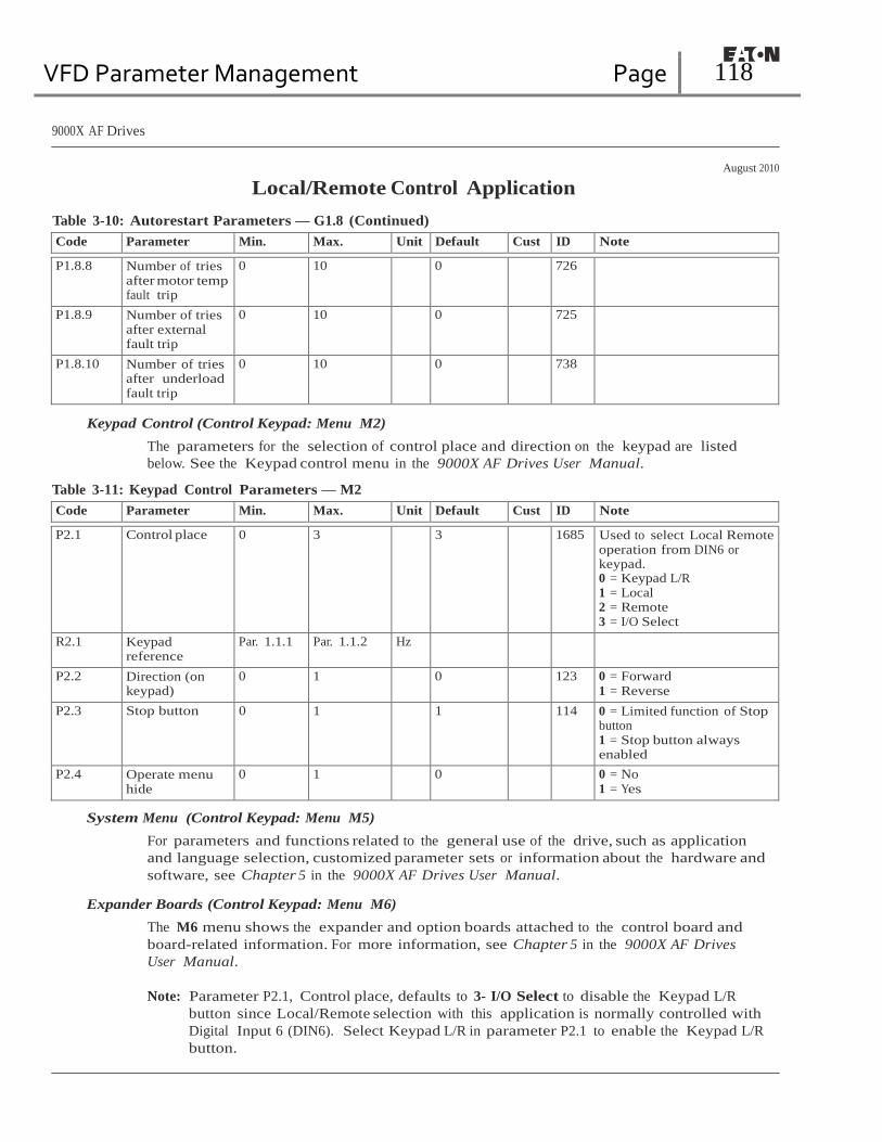
VFD Parameter Management Page 118
9000X AF Drives
August 2010
Local/Remote Control Application
Table 3-10: Autorestart Parameters — G1.8 (Continued)
Code Parameter Min. Max. Unit Default Cust ID Note
P1.8.8 Number of tries after motor temp fault trip
0 10 0 726
P1.8.9 Number of tries after external fault trip
0 10 0 725
P1.8.10 Number of tries after underload fault trip
0 10 0 738
Keypad Control (Control Keypad: Menu M2)
The parameters for the selection of control place and direction on the keypad are listed
below. See the Keypad control menu in the 9000X AF Drives User Manual.
Table 3-11: Keypad Control Parameters — M2
Code Parameter Min. Max. Unit Default Cust ID Note
P2.1 Control place 0 3 3 1685 Used to select Local Remote operation from DIN6 or keypad. 0 = Keypad L/R 1 = Local 2 = Remote 3 = I/O Select
R2.1 Keypad reference
Par. 1.1.1 Par. 1.1.2 Hz
P2.2 Direction (on keypad)
0 1 0 123 0 = Forward 1 = Reverse
P2.3 Stop button 0 1 1 114 0 = Limited function of Stop button 1 = Stop button always enabled
P2.4 Operate menu hide
0 1 0 0 = No 1 = Yes
System Menu (Control Keypad: Menu M5)
For parameters and functions related to the general use of the drive, such as application
and language selection, customized parameter sets or information about the hardware and
software, see Chapter 5 in the 9000X AF Drives User Manual.
Expander Boards (Control Keypad: Menu M6)
The M6 menu shows the expander and option boards attached to the control board and
board-related information. For more information, see Chapter 5 in the 9000X AF Drives
User Manual.
Note: Parameter P2.1, Control place, defaults to 3- I/O Select to disable the Keypad L/R
button since Local/Remote selection with this application is normally controlled with
Digital Input 6 (DIN6). Select Keypad L/R in parameter P2.1 to enable the Keypad L/R
button.
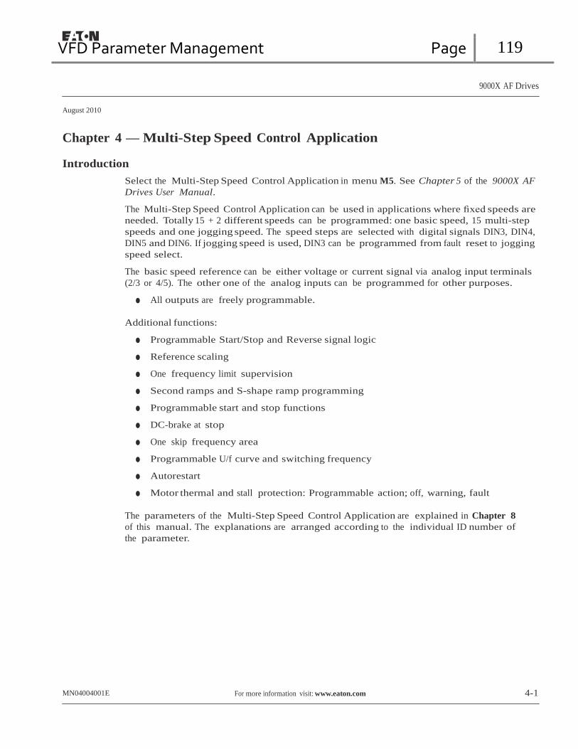
VFD Parameter Management Page 119
9000X AF Drives
August 2010
Chapter 4 — Multi-Step Speed Control Application Introduction
Select the Multi-Step Speed Control Application in menu M5. See Chapter 5 of the 9000X AF
Drives User Manual.
The Multi-Step Speed Control Application can be used in applications where fixed speeds are
needed. Totally 15 + 2 different speeds can be programmed: one basic speed, 15 multi-step
speeds and one jogging speed. The speed steps are selected with digital signals DIN3, DIN4,
DIN5 and DIN6. If jogging speed is used, DIN3 can be programmed from fault reset to jogging
speed select.
The basic speed reference can be either voltage or current signal via analog input terminals
(2/3 or 4/5). The other one of the analog inputs can be programmed for other purposes.
● All outputs are freely programmable.
Additional functions:
● Programmable Start/Stop and Reverse signal logic
● Reference scaling
● One frequency limit supervision
● Second ramps and S-shape ramp programming
● Programmable start and stop functions
● DC-brake at stop
● One skip frequency area
● Programmable U/f curve and switching frequency
● Autorestart
● Motor thermal and stall protection: Programmable action; off, warning, fault
The parameters of the Multi-Step Speed Control Application are explained in Chapter 8
of this manual. The explanations are arranged according to the individual ID number of
the parameter.
MN04004001E For more information visit: www.eaton.com 4-1

VFD Parameter Management Page 120
Sel1 Sel2 Sel3 Sel4 (with DIN3) 0
1
0
…
1
0
0
1
1
0
0
0
1
0 Basic speed
0 Speed 1
0 Speed 2
…
1 Speed 15
9000X AF Drives
August 2010
Control I/O
Remote reference pot. 1 – 10 kW
Multi-Step Speed Control Application
Table 4-1: Multi-Step Speed Control Application Default I/O Configuration
Terminal Signal Description
OPTA1
1 +10Vref Reference output Voltage for potentiometer, etc.
2 AI1+ Analog input, voltage range 0 – 10V DC
Basic reference (programmable) range 0 – 10V DC
3 AI1- I/O Ground Ground for reference and controls
Basic Reference 4 AI2+ Analog input, current range Basic reference (programmable) (optional)
5 AI2- 0 – 20 mA range 0 – 20 mA
6 +24V Control voltage output Voltage for switches, etc. max 0.1A
7 GND I/O ground Ground for reference and controls
8 DIN1 Start forward (programmable) Contact closed = start forward
9 DIN2 Start reverse (programmable) Contact closed = start reverse
10 DIN3 External fault input (programmable)
Contact open = no fault Contact closed = fault
11 CMA Common for DIN1 – DIN3 Connect to GND or +24V
12 +24V Control voltage output Voltage for switches (see terminal 6)
13 GND I/O ground Ground for reference and controls
14 DIN4 Multi-step speed select 1
15 DIN5 Multi-step speed select 2
16 DIN6 Multi-step speed select 3
17 CMB Common for DIN4 – DIN6 Connect to GND or +24V
18 AO1+ Output frequency Programmable
mA 19 AO1- Analog output Range 0 – 20 mA, RL, max. 500W
READY 20 DO1 Digital output
READY
Programmable
Open collector, I ≤ 50 mA, V ≤ 48V DC
OPTA2
21 RO1 Relay output 1 Programmable
RUN 22 RO1
23 RO1
RUN
24 RO2 Relay output 2 Programmable
220V
AC
25 RO2
26 RO2
FAULT
Note: For more information on jumper selections, see the 9000X AF Drives User
Manual, Chapter 4. Jumper Block X3:
CMA and CMB Grounding
CMB connected to GND
CMA connected to GND CMB isolated from GND
CMA isolated from GND
CMB and CMA internally connected together, isolated from GND

VFD Parameter Management Page 121
9000X AF Drives
August 2010
Multi-Step Speed Control Application
Multi-Step Speed Control Application — Parameter Lists
On the next pages you will find the lists of parameters within the respective parameter

VFD Parameter Management Page 122
9000X AF Drives
August 2010
Multi-Step Speed Control Application
Basic Parameters (Control Keypad: Menu M1 ➔ G1.1)
Table 4-3: Basic Parameters — G1.1
Code Parameter Min. Max. Unit Default Cust ID Note P1.1.1 Min frequency 0.00 Par. 1.1.2 Hz 0.00 101 P1.1.2 Max frequency Par. 1.1.1 320.00 Hz 60.00 102 NOTE: If fmax > than the
motor synchronous speed, check suitability for motor and drive system.
P1.1.3 Acceleration time 1 0.1 3000.0 s 3.0 103 P1.1.4 Deceleration time 1 0.1 3000.0 s 3.0 104 P1.1.5 Current limit 0.4 x IH 2 x IH A IL 107 P1.1.6 Nominal voltage of the
motor 180 690 V P: 230V
P: 460V P: 575V
110
P1.1.7 Nominal frequency of the motor
30.00 320.00 Hz 60.00 111 Check the rating plate of the motor.
P1.1.8 Nominal speed of the motor
300 20 000 rpm 1720 112 The default applies for a 4-pole motor and a nominal size frequency converter.
P1.1.9 Nominal current of the motor
0.4 x IH 2 x IH A IH 113 Check the rating plate of the motor.
P1.1.10 Power Factor 0.30 1.00 0.85 120 Check the rating plate of the motor.
P1.1.11 Local control place 0 3 1 171 1 = I/O Terminal 2 = Keypad 3 = Fieldbus
P1.1.12 Remote control place 0 3 1 172 1 = I/O Terminal 2 = Keypad 3 = Fieldbus
P1.1.13 Local control reference 0 3 2 173 0 = AI1 1 = AI2 2 = Keypad 3 = Fieldbus
P1.1.14 Remote control reference
0 3 0 174 0 = AI1 1 = AI2 2 = Keypad 3 = Fieldbus
P1.1.15 Motor Id 0 2 0 631 0 = Not user 1 = V/Hz 2 = V/Hz with boost
P1.1.16 V/Hz opt 0 1 0 109 0 = Not used 1 = Automatic torque boost
P1.1.17 Jogging speed pref. 0.00 Par. 1.1.2 Hz 0.00 124 P1.1.18 Preset speed 1 0.00 Par. 1.1.2 Hz 5.00 105 Multi-step speed 1 P1.1.19 Preset speed 2 0.00 Par. 1.1.2 Hz 10.00 106 Multi-step speed 2 P1.1.20 Preset speed 3 0.00 Par. 1.1.2 Hz 12.50 126 Multi-step speed 3 P1.1.21 Preset speed 4 0.00 Par. 1.1.2 Hz 15.00 127 Multi-step speed 4
P1.1.22 Preset speed 5 0.00 Par. 1.1.2 Hz 17.50 128 Multi-step speed 5 P1.1.23 Preset speed 6 0.00 Par. 1.1.2 Hz 20.00 129 Multi-step speed 6
4-4 For more information visit: www.eaton.com MN04004001E
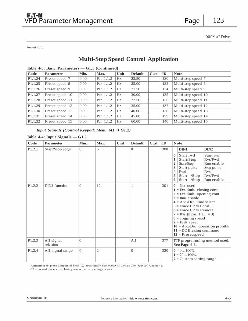
VFD Parameter Management Page 123
9000X AF Drives
August 2010
Multi-Step Speed Control Application
Table 4-3: Basic Parameters — G1.1 (Continued)
Code Parameter Min. Max. Unit Default Cust ID Note P1.1.24 Preset speed 7 0.00 Par. 1.1.2 Hz 22.50 130 Multi-step speed 7 P1.1.25 Preset speed 8 0.00 Par. 1.1.2 Hz 25.00 133 Multi-step speed 8 P1.1.26 Preset speed 9 0.00 Par. 1.1.2 Hz 27.50 134 Multi-step speed 9
P1.1.27 Preset speed 10 0.00 Par. 1.1.2 Hz 30.00 135 Multi-step speed 10 P1.1.28 Preset speed 11 0.00 Par. 1.1.2 Hz 32.50 136 Multi-step speed 11
P1.1.29 Preset speed 12 0.00 Par. 1.1.2 Hz 35.00 137 Multi-step speed 12 P1.1.30 Preset speed 13 0.00 Par. 1.1.2 Hz 40.00 138 Multi-step speed 13 P1.1.31 Preset speed 14 0.00 Par. 1.1.2 Hz 45.00 139 Multi-step speed 14 P1.1.32 Preset speed 15 0.00 Par. 1.1.2 Hz 60.00 140 Multi-step speed 15
Input Signals (Control Keypad: Menu M1 ➔ G1.2)
Table 4-4: Input Signals — G1.2
Code Parameter Min. Max. Unit Default Cust ID Note
P1.2.1 Start/Stop logic 0 6 0 300
0 1 2 3 4 5 6
DIN1 DIN2
Start fwd Start/Stop Start/Stop Start pulse Fwd
Start /Stop Start /Stop
Start rvs Rvs/Fwd Run enable Stop pulse Rvs
Rvs/Fwd Run enable
P1.2.2 DIN3 function 0 12 1 301 0 = Not used 1 = Ext. fault. closing cont. 2 = Ext. fault. opening cont. 3 = Run enable 4 = Acc./Dec. time select. 5 = Force CP to Local
6 = Force CP to Remote
7 = Rvs (if par. 1.2.1 = 3) 8 = Jogging speed 9 = Fault reset 10 = Acc./Dec. operation prohibit 11 = DC Braking command 12 = Preset speed
P1.2.3 AI1 signal selection
0 A.1 377 TTF programming method used. See Page 6-3.
P1.2.4 AI1 signal range 0 2 0 320 0 = 0…100%
1 = 20…100%
2 = Custom setting range
Remember to place jumpers of block X2 accordingly. See 9000X AF Drives User Manual, Chapter 4. CP = control place; cc = closing contact; oc = opening contact.
MN04004001E For more information visit: www.eaton.com 4-5
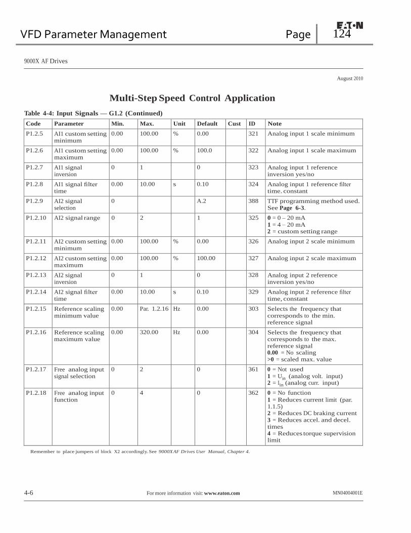
VFD Parameter Management Page 124
9000X AF Drives
August 2010
Multi-Step Speed Control Application
Table 4-4: Input Signals — G1.2 (Continued)
Code Parameter Min. Max. Unit Default Cust ID Note
P1.2.5 AI1 custom setting minimum
0.00 100.00 % 0.00 321 Analog input 1 scale minimum
P1.2.6 AI1 custom setting maximum
0.00 100.00 % 100.0 322 Analog input 1 scale maximum
P1.2.7 AI1 signal inversion
0 1 0 323 Analog input 1 reference inversion yes/no
P1.2.8 AI1 signal filter time
0.00 10.00 s 0.10 324 Analog input 1 reference filter time. constant
P1.2.9 AI2 signal selection
0 A.2 388 TTF programming method used. See Page 6-3.
P1.2.10 AI2 signal range 0 2 1 325 0 = 0 – 20 mA
1 = 4 – 20 mA
2 = custom setting range
P1.2.11 AI2 custom setting minimum
0.00 100.00 % 0.00 326 Analog input 2 scale minimum
P1.2.12 AI2 custom setting maximum
0.00 100.00 % 100.00 327 Analog input 2 scale maximum
P1.2.13 AI2 signal inversion
0 1 0 328 Analog input 2 reference inversion yes/no
P1.2.14 AI2 signal filter time
0.00 10.00 s 0.10 329 Analog input 2 reference filter time, constant
P1.2.15 Reference scaling minimum value
0.00 Par. 1.2.16 Hz 0.00 303 Selects the frequency that corresponds to the min. reference signal
P1.2.16 Reference scaling maximum value
0.00 320.00 Hz 0.00 304 Selects the frequency that corresponds to the max. reference signal 0.00 = No scaling >0 = scaled max. value
P1.2.17 Free analog input signal selection
0 2 0 361 0 = Not used 1 = Uin (analog volt. input) 2 = Iin (analog curr. input)
P1.2.18 Free analog input function
0 4 0 362 0 = No function
1 = Reduces current limit (par. 1.1.5) 2 = Reduces DC braking current 3 = Reduces accel. and decel. times 4 = Reduces torque supervision limit
Remember to place jumpers of block X2 accordingly. See 9000X AF Drives User Manual, Chapter 4.
4-6 For more information visit: www.eaton.com MN04004001E

VFD Parameter Management Page 125
9000X AF Drives
August 2010
Multi-Step Speed Control Application
Output Signals (Control Keypad: Menu M1 ➔ G1.3)
Table 4-5: Output Signals — G1.3
Code Parameter Min. Max. Unit Default Cust ID Note P1.3.1 AO1 signal selection 0 A.1 464 TTF programming method used.
See Page 6-3. P1.3.2 Analog output function 0 8 1 307 0 = Not used
1 = Output freq. (0 – fmax) 2 = Freq. reference (0 – fmax) 3 = Motor speed (0 – Motor nominal speed) 4 = Motor current (0 – InMotor) 5 = Motor torque (0 – TnMotor) 6 = Motor power (0 – PnMotor) 7 = Motor voltage (0 – UnMotor) 8 = DC-bus volt (0 – 1000V)
P1.3.3 Analog output filter time
0.00 10.00 s 1.00 308 0 = No filtering
P1.3.4 Analog output inversion
0 1 0 309 0 = Not inverted 1 = Inverted
P1.3.5 Analog output minimum
0 1 0 310 0 = 0 mA 1 = 4 mA
P1.3.6 Analog output scale 10 1000 % 100 311 P1.3.7 Digital output 1
function 0 22 1 312 0 = Not used
1 = Ready 2 = Run 3 = Fault 4 = Fault inverted 5 = FC overheat warning 6 = Ext. fault or warning 7 = Ref. fault or warning 8 = Warning 9 = Reversed 10 = Jogging spd selected 11 = At speed 12 = Mot. regulator active 13 = OP freq.limit superv. 1 14 = OP freq.limit superv. 2 15 = Torque limit superv. 16 = Ref. limit superv. 17 = Ext. brake control 18 = Remote Control Active 19 = FC temp. limit superv. 20 = Unrequested rotation direction 21 = Ext. brake control inverted 22 = Thermistor fault/warn.
P1.3.8 Relay output 1 function 0 22 2 313 Same as parameter 1.3.7 P1.3.9 Relay output 2 function 0 22 3 314 Same as parameter 1.3.7 P1.3.10 Output frequency limit
1 supervision 0 2 0 315 0 = No limit
1 = Low limit supervision 2 = High limit supervision
MN04004001E For more information visit: www.eaton.com 4-7

VFD Parameter Management Page 126
9000X AF Drives
August 2010
Multi-Step Speed Control Application
Table 4-5: Output Signals — G1.3 (Continued)
Code Parameter Min. Max. Unit Default Cust ID Note P1.3.11 Output frequency limit
1; Supervision value 0.00 320.00 Hz 0.00 316
P1.3.12 Output frequency limit 2 supervision
0 2 0 346 0 = No limit 1 = Low limit supervision 2 = High limit supervision
P1.3.13 Output frequency limit 2; Supervision value
0.00 320.00 Hz 0.00 347
P1.3.14 Torque limit supervision function
0 2 0 348 0 = No 1 = Low limit 2 = High limit
P1.3.15 Torque limit supervision value
0.0 200.0 % 0 349
P1.3.16 Reference limit supervision function
0 2 0 350 0 = No 1 = Low limit 2 = High limit
P1.3.17 Reference limit supervision value
0.0 100.0 % 0.0 351
P1.3.18 External brake Off- delay
0.0 100.0 s 0.5 352
P1.3.19 External brake On- delay
0.0 100.0 s 1.5 353
P1.3.20 Frequency converter temperature limit supervision
0 2 0 354 0 = No 1 = Low limit 2 = High limit
P1.3.21 Frequency converter temperature limit value
-10 75 ∞C 0 355
P1.3.22 Analog output 2 signal selection
0 0.1 471 TTF programming method used. See Page 6-3.
P1.3.23 Analog output 2 function
0 8 4 472 Same as parameter 1.3.2
P1.3.24 Analog output 2 filter time
0.00 10.00 s 1.00 473 0 = No filtering
P1.3.25 Analog output 2 inversion
0 1 0 474 0 = Not inverted 1 = Inverted
P1.3.26 Analog output 2 minimum
0 1 0 475 0 = 0 mA 1 = 4 mA
P1.3.27 Analog output 2 scaling 10 1000 % 100 476
4-8 For more information visit: www.eaton.com MN04004001E

VFD Parameter Management Page 127
9000X AF Drives
August 2010
Multi-Step Speed Control Application
Drive Control Parameters (Control Keypad: Menu M1 ➔ G1.4)
Table 4-6: Drive Control Parameters — G1.4
Code Parameter Min. Max. Unit Default Cust ID Note P1.4.1 Ramp 1 shape 0.0 10.0 s 0.0 500 0 = Linear
>0 = S-curve ramp time P1.4.2 Ramp 2 shape 0.0 10.0 s 0.0 501 0 = Linear
>0 = S-curve ramp time P1.4.3 Acceleration time 2 0.1 3000.0 s 10.0 502 P1.4.4 Deceleration time 2 0.1 3000.0 s 10.0 503 P1.4.5 Brake chopper 0 4 0 504 0 = Disabled
1 = Used when running 2 = External brake chopper 3 = Used when stopped/running 4 = Used when running (no testing)
P1.4.6 Start function 0 1 0 505 0 = Ramp 1 = Flying start
P1.4.7 Stop function 0 3 1 506 0 = Coasting 1 = Ramp 2 = Ramp+Run enable coast 3 = Coast+Run enable ramp
P1.4.8 DC braking current 0.4 x IH 2 x IH A IH 507 P1.4.9 DC braking time
at stop 0.00 600.00 s 0.00 508 0 = DC brake is off at stop
P1.4.10 Frequency to start DC braking during ramp stop
0.10 10.00 Hz 1.50 515
P1.4.11 DC braking time at start
0.00 600.00 s 0.00 516 0 = DC brake is off at start
P1.4.12 Flux brake 0 1 0 520 0 = Off 1 = On
P1.4.13 Flux braking current 0.4 x IH 2 x IH A IH 519
Skip Frequency Parameters (Control Keypad: Menu M1 ➔ G1.5)
Table 4-7: Skip Frequency Parameters — G1.5
Code Parameter Min. Max. Unit Default Cust ID Note P1.5.1 Skip frequency
range 1 low limit 0.00 par.
1.5.2 Hz 0.00 509
P1.5.2 Skip frequency range 1 high limit
0.00 par. 1.1.2
Hz 0.0 510 0 = Skip frequency range 1 not used
P1.5.3 Skip frequency range 2 low limit
0.00 par. 1.5.2
Hz 0.00 511
P1.5.4 Skip frequency range 2 high limit
0.00 par. 1.1.2
Hz 0.0 512 0 = Skip frequency range 2 not used
P1.5.5 Skip frequency range 3 low limit
0.00 par. 1.5.2
Hz 0.00 513
P1.5.6 Skip frequency range 3 high limit
0.00 par. 1.1.2
Hz 0.0 514 0 = Skip frequency range 3 not used
P1.5.7 Skip frequency acc./dec. ramp
0.1 10.0 1.0 518
MN04004001E For more information visit: www.eaton.com 4-9

VFD Parameter Management Page 128
9000X AF Drives
August 2010
Multi-Step Speed Control Application
Motor Control Parameters (Control Keypad: Menu M1 ➔ G1.6)
Table 4-8: Motor Control Parameters — G1.6
Code Parameter Min. Max. Unit Default Cust ID Note P1.6.1 Motor control mode 0 1/6 0 600 SVX:
0 = Frequency control 1 = Speed control Additionally for SPX: 2 = Torque control 3 = Closed loop speed ctrl 4 = Closed loop torque ctrl
P1.6.2 V/Hz optimization 0 1 0 109 0 = Not used 1 = Automatic torque boost
P1.6.3 V/Hzf ratio selection 0 3 0 108 0 = Linear 1 = Squared 2 = Programmable 3 = Linear with flux optim.
P1.6.4 Field weakening point 8.00 320.00 Hz 60.00 602 P1.6.5 Voltage at field
weakening point 10.00 200.00 % 100.00 603 n% x Unmot
P1.6.6 V/Hz curve midpoint frequency
0.00 Par. 1.6.4 Hz 60.00 604
P1.6.7 V/Hz curve midpoint voltage
0.00 100.00 % 100.00 605 n% x Unmot
Parameter max. value = par. 1.6.5 P1.6.8 Output voltage at zero
frequency 0.00 40.00 % 1.30 606 n% x Unmot
P1.6.9 Switching frequency 1.0 Varies kHz Varies 601 See Table 8-12 on Page 8-57 for exact values
P1.6.10 Overvoltage controller 0 2 1 607 0 = Not used 1 = Used (no ramping) 2 = Used (ramping
P1.6.11 Undervoltage controller
0 1 1 608 0 = Not used 1 = Used
P1.6.12 Load Drooping 0.00 100.00 0.00 620 Drooping % of nominal speed at nominal torque
P1.6.13 Identification 0 1 0 631 0 = Not used 1 = V/Hz 2 = V/H w/boost
4-10 For more information visit: www.eaton.com MN04004001E
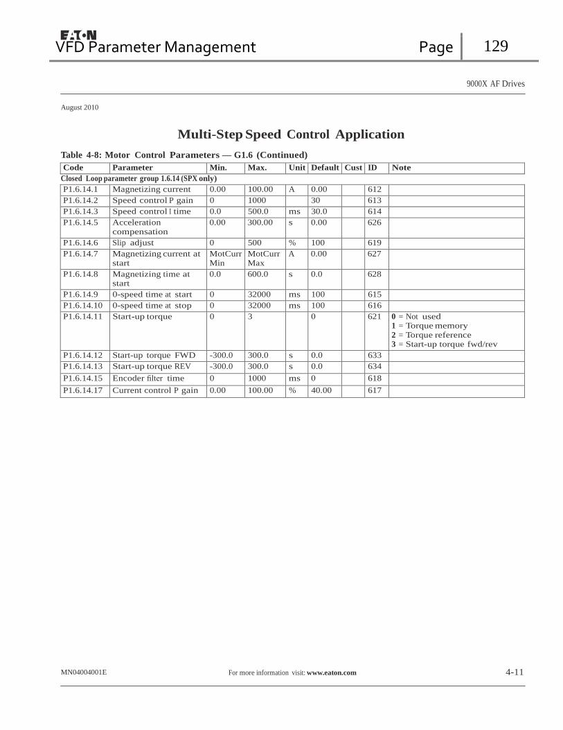
VFD Parameter Management Page 129
9000X AF Drives
August 2010
Multi-Step Speed Control Application
Table 4-8: Motor Control Parameters — G1.6 (Continued)
Code Parameter Min. Max. Unit Default Cust ID Note Closed Loop parameter group 1.6.14 (SPX only)
P1.6.14.1 Magnetizing current 0.00 100.00 A 0.00 612 P1.6.14.2 Speed control P gain 0 1000 30 613 P1.6.14.3 Speed control I time 0.0 500.0 ms 30.0 614 P1.6.14.5 Acceleration
compensation 0.00 300.00 s 0.00 626
P1.6.14.6 Slip adjust 0 500 % 100 619 P1.6.14.7 Magnetizing current at
start MotCurr Min
MotCurr Max
A 0.00 627
P1.6.14.8 Magnetizing time at start
0.0 600.0 s 0.0 628
P1.6.14.9 0-speed time at start 0 32000 ms 100 615 P1.6.14.10 0-speed time at stop 0 32000 ms 100 616 P1.6.14.11 Start-up torque 0 3 0 621 0 = Not used
1 = Torque memory 2 = Torque reference 3 = Start-up torque fwd/rev
P1.6.14.12 Start-up torque FWD -300.0 300.0 s 0.0 633 P1.6.14.13 Start-up torque REV -300.0 300.0 s 0.0 634 P1.6.14.15 Encoder filter time 0 1000 ms 0 618 P1.6.14.17 Current control P gain 0.00 100.00 % 40.00 617
MN04004001E For more information visit: www.eaton.com 4-11

VFD Parameter Management Page 130
9000X AF Drives
August 2010
Multi-Step Speed Control Application
Protections (Control Keypad: Menu M1 ➔ G1.7)
Table 4-9: Protections — G1.7
Code Parameter Min. Max. Unit Default Cust ID Note P1.7.1 Response to
reference fault 0 5 0 700 0 = No response
1 = Warning 2 = Warning+Previous Freq. 3 = Wrng+PresetFreq 1.7.2 4 = Fault.stop acc. to 1.4.7 5 = Fault.stop by coasting
P1.7.2 4mA reference fault frequency
0.00 Par. 1.1.2 Hz 0.00 728
P1.7.3 Response to external fault
0 3 2 701 0 = No response 1 = Warning 2 = Fault.stop acc. to 1.4.7 3 = Fault.stop by coasting
P1.7.4 Input phase supervision
0 3 3 730
P1.7.5 Response to undervoltage fault
1 3 0 727
P1.7.6 Output phase supervision
0 3 2 702
P1.7.7 Earth fault protection 0 3 2 703 P1.7.8 Thermal protection of
the motor 0 3 2 704
P1.7.9 Motor ambient temperature factor
-100.0 100.0 % 0.0 705
P1.7.10 Motor cooling factor at zero speed
0.0 150.0 % 40.0 706
P1.7.11 Motor thermal time constant
1 200 min 45 707
P1.7.12 Motor duty cycle 0 100 % 100 708 P1.7.13 Stall protection 0 3 0 709 0 = No response
1 = Warning 2 = Fault.stop acc. to 1.4.7 3 = Fault.stop by coasting
P1.7.14 Stall current 0.1 InMotor x 2
A IL 710
P1.7.15 Stall time limit 1.00 120.00 s 15.00 711 P1.7.16 Stall frequency limit 1.0 Par. 1.1.2 Hz 25.0 712 P1.7.17 Underload protection 0 3 0 713 0 = No response
1 = Warning 2 = Fault.stop acc. to 1.4.7 3 = Fault.stop by coasting
P1.7.18 Field weakening area load
10 150 % 50 714
P1.7.19 Zero frequency load 5.0 150.0 % 10.0 715 P1.7.20 Underload protection
time limit 2 600 s 20 716
P1.7.21 Response to thermistor fault
0 3 2 732 0 = No response 1 = Warning 2 = Fault.stop acc. to 1.4.7 3 = Fault.stop by coasting
P1.7.22 Response to fieldbus fault
0 3 2 733 See P1.7.21
P1.7.23 Response to slot fault 0 3 2 734 See P1.7.21
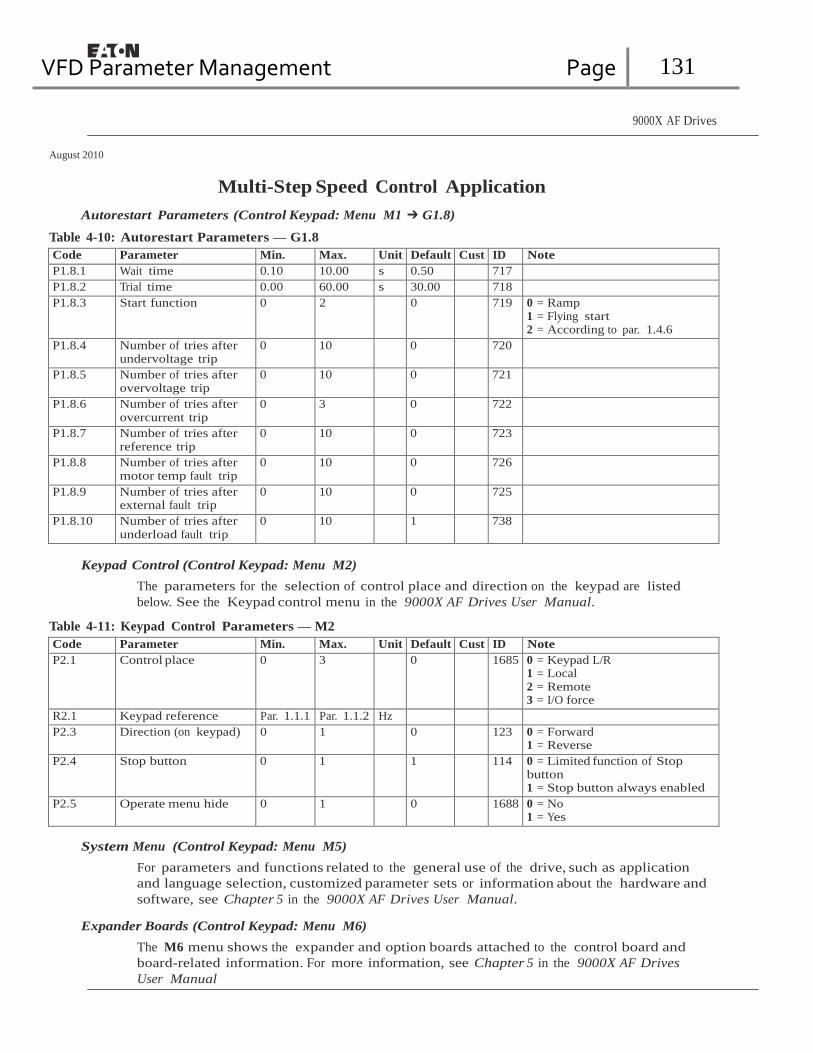
VFD Parameter Management Page 131
9000X AF Drives
August 2010
Multi-Step Speed Control Application
Autorestart Parameters (Control Keypad: Menu M1 ➔ G1.8)
Table 4-10: Autorestart Parameters — G1.8
Code Parameter Min. Max. Unit Default Cust ID Note P1.8.1 Wait time 0.10 10.00 s 0.50 717 P1.8.2 Trial time 0.00 60.00 s 30.00 718 P1.8.3 Start function 0 2 0 719 0 = Ramp
1 = Flying start 2 = According to par. 1.4.6
P1.8.4 Number of tries after undervoltage trip
0 10 0 720
P1.8.5 Number of tries after overvoltage trip
0 10 0 721
P1.8.6 Number of tries after overcurrent trip
0 3 0 722
P1.8.7 Number of tries after reference trip
0 10 0 723
P1.8.8 Number of tries after motor temp fault trip
0 10 0 726
P1.8.9 Number of tries after external fault trip
0 10 0 725
P1.8.10 Number of tries after underload fault trip
0 10 1 738
Keypad Control (Control Keypad: Menu M2)
The parameters for the selection of control place and direction on the keypad are listed
below. See the Keypad control menu in the 9000X AF Drives User Manual.
Table 4-11: Keypad Control Parameters — M2
Code Parameter Min. Max. Unit Default Cust ID Note P2.1 Control place 0 3 0 1685 0 = Keypad L/R
1 = Local 2 = Remote 3 = I/O force
R2.1 Keypad reference Par. 1.1.1 Par. 1.1.2 Hz P2.3 Direction (on keypad) 0 1 0 123 0 = Forward
1 = Reverse P2.4 Stop button 0 1 1 114 0 = Limited function of Stop
button 1 = Stop button always enabled
P2.5 Operate menu hide 0 1 0 1688 0 = No 1 = Yes
System Menu (Control Keypad: Menu M5)
For parameters and functions related to the general use of the drive, such as application
and language selection, customized parameter sets or information about the hardware and
software, see Chapter 5 in the 9000X AF Drives User Manual.
Expander Boards (Control Keypad: Menu M6)
The M6 menu shows the expander and option boards attached to the control board and
board-related information. For more information, see Chapter 5 in the 9000X AF Drives
User Manual

VFD Parameter Management Page 132
9000X AF Drives
August 2010
Chapter 5 — PID Control Application Introduction
Select the PID Control Application in menu M5. See Chapter 5 of the 9000X AF Drives
User Manual.
In the PID Control Application, there are two I/O terminal control places; place A is the PID
controller and source B is the direct frequency reference. The control place A or B is selected
with digital input DIN6.
The PID controller reference can be selected from the analog inputs, fieldbus, motorized
potentiometer, enabling the PID Reference 2 or applying the control keypad reference. The
PID controller actual value can be selected from the analog inputs, fieldbus, the actual values
of the motor or through the mathematical functions of these.
The direct frequency reference can be used for the control without the PID controller and
selected from the analog inputs, fieldbus, motor potentiometer or keypad.
The PID Application is typically used to control level measuring or pumps and fans. In these
applications, the PID Application provides a smooth control and an integrated measuring and
controlling package where no additional components are needed.
● Digital inputs DIN2, DIN3, DIN5 and all the outputs are freely programmable.
Additional functions:
● Analog input signal range selection
● Two frequency limit supervisions
● Torque limit supervision
● Reference limit supervision
● Second ramps and S-shape ramp programming
● Programmable start and stop functions
● DC-brake at start and stop
● Three skip frequency areas
● Programmable U/f curve and switching frequency
● Autorestart
● Motor thermal and stall protection: fully programmable; off, warning, fault
● Motor underload protection
● Input and output phase supervision
● Sum point frequency addition to PID output
● The PID controller can additionally be used from control places I/O B, keypad and fieldbus
● Easy ChangeOver function
● Sleep function
The parameters of the PID Control Application are explained in Chapter 8 of this manual.
The explanations are arranged according to the individual ID number of the parameter.

VFD Parameter Management Page 133
9000X AF DrivesAugust 2010
Control I/O
Reference potentiometer 1 – 10 kW
PID Control Application
Table 5-1: PID Application Default I/O Configuration (with 2-wire transmitter)
Terminal Signal Description
OPTA1
1 +10Vref Reference output Voltage for potentiometer, etc.
2-wire
2 AI1+ Analog input, voltage range 0 – 10V DC
Voltage input frequency reference
transmitter 3 AI1- I/O Ground Ground for reference and controls
+ Actual value 4 AI2+ Analog input, current range Current input frequency reference - + 5 AI2- 0 – 20 mA
- (0)4 … 20 mA 6 +24V Control voltage output Voltage for switches, etc. max 0.1A
7 GND I/O ground Ground for reference and controls
8 DIN1 Start/Stop
Control place A (PID controller)
9 DIN2 External fault input (programmable)
Contact closed = fault
Contact open = no fault
Contact closed = fault Contact open = no fault
10 DIN3 Fault reset (programmable) Contact closed = fault reset
11 CMA Common for DIN1 – DIN3 Connect to GND or +24V
12 +24V Control voltage output Voltage for switches (see #6)
13 GND I/O ground Ground for reference and controls
14 DIN4 Start/Stop Control place B (Direct frequency reference)
15 DIN5 Jogging speed selection (programmable)
Contact closed = Start
Contact closed = Jogging speed active
16 DIN6 Control place A/B selection Contact open = Control place A is active Contact closed = Control place B is active
17 CMB Common for DIN4 – DIN6 Connect to GND or +24V
18 AO1+ Output frequency Programmable
READY
mA 19 AO1-
Analog output Range 0 – 20 mA/RL, max. 500W
20 DO1 Digital output READY
Programmable Open collector, I ≤ 50 mA, U ≤ 48V DC
OPTA2
21 RO1 Relay output 1 Programmable
RUN 22 RO1
23 RO1
RUN
24 RO2 Relay output 2 Programmable
220V
AC
25 RO2
26 RO2
FAULT
Note: For more information on jumper selections, see the 9000X AF Drives User
Manual, Chapter 4. Jumper Block X3: CMA and CMB Grounding
CMB connected to GND
CMA connected to GND CMB isolated from GND
CMA isolated from GND
CMB and CMA internally connected together, isolated from GND
= Factory default.

VFD Parameter Management Page 134
9000X AF Drives
August 2010
PID Control Application
PID Control Application — Parameter Lists
On the next pages you will find the lists of parameters within the respective parameter
groups. The parameter descriptions are given in Chapter 8.
Column explanations:
Code = Location indication on the keypad; Shows the operator the present parameter
number
Parameter = Name of parameter
Min = Minimum value of parameter
Max = Maximum value of parameter
Unit = Unit of parameter value; Given if available
Default = Value preset by factory
Cust = Customer’s own setting
ID = ID number of the parameter
= Parameter value can only be changed after the drive has been stopped.
= Use TTF method to program these parameters. See Page 6-3.
Monitoring Values (Control Keypad: Menu M7)
The monitoring values are the actual values of parameters and signals as well as statuses
and measurements. Monitoring values cannot be edited.
See 9000X AF Drives User Manual, Chapter 5 for more information. Note that the monitoring
values V1.19 to V1.22 are available with the PID control application only.
Table 5-2: Monitoring Values
Code Parameter Unit ID Description
V1.1 Output frequency Hz 1 Output frequency to motor
V1.2 Frequency reference Hz 25 Frequency reference to motor control
V1.3 Motor speed rpm 2 Motor speed in rpm
V1.4 Motor current A 3
V1.5 Motor torque % 4 In % of Motor nom. torque
V1.6 Motor power % 5 Motor shaft power
V1.7 Motor voltage V 6
V1.8 DC Bus voltage V 7
V1.9 Unit temperature ∞C 8 Heatsink temperature
V1.10 Motor temperature % 9 Calculated motor temperature
V1.11 Analog input 1 V 13 AI1
V1.12 Analog input 2 mA 14 AI2
V1.13 Analog input 3 27 AI3
V1.14 Analog input 4 28 AI4
V1.15 DIN1, DIN2, DIN3 15 Digital input statuses
MN04004001E For more information visit: www.eaton.com 5-3
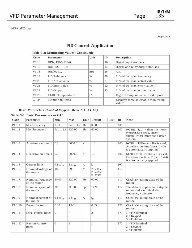
VFD Parameter Management Page 135
9000X AF Drives
August 2010
PID Control Application
Table 5-2: Monitoring Values (Continued)
Code Parameter Unit ID Description
V1.16 DIN4, DIN5, DIN6 16 Digital input statuses
V1.17 DO1, RO1, RO2 17 Digital and relay output statuses
V1.18 Analog Iout mA 26 AO1
V1.19 PID Reference % 20 In % of the max. frequency
V1.20 PID Actual value % 21 In % of the max. actual value
V1.21 PID Error value % 22 In % of the max. error value
V1.22 PID Output % 23 In % of the max. output value
V1.23 PT-100 Temperature Cº Highest temperature of used inputs
G1.24 Monitoring items Displays three selectable monitoring values
Basic Parameters (Control Keypad: Menu M1 ➔ G1.1)
Table 5-3: Basic Parameters — G1.1
Code Parameter Min. Max. Unit Default Cust ID Note
P1.1.1 Min frequency 0.00 Par. 1.1.2 Hz 0.00 101 P1.1.2 Max frequency Par. 1.1.1 320.00 Hz 60.00 102 NOTE: If fmax > than the motor
synchronous speed. check suitability for motor and drive system
P1.1.3 Acceleration time 1 0.1 3000.0 s 1.0 103 NOTE: If PID-controller is used, Acceleration time 2 (par. 1.4.3) is automatically applied
P1.1.4 Deceleration time 1 0.1 3000.0 s 1.0 104 NOTE: If PID-controller is used, Deceleration time 2 (par. 1.4.4) is automatically applied
P1.1.5 Current limit 0.1 x IH 2 x IH A IL 107 P1.1.6 Nominal voltage of
the motor 180 690 V P: 230V
P: 460V P: 575V
110
P1.1.7 Nominal frequency of the motor
30.00 320.00 Hz 60.00 111 Check the rating plate of the motor
P1.1.8 Nominal speed of the motor
300 20 000 rpm 1720 112 The default applies for a 4-pole motor and a nominal size frequency converter.
P1.1.9 Nominal current of the motor
0.1 x IH 2 x IH A IH 113 Check the rating plate of the motor.
P1.1.10 Power Factor 0.30 1.00 0.85 120 Check the rating plate of the motor
P1.1.11 Local control place 0 3 2 171 1 = I/O Terminal 2 = Keypad 3 = Fieldbus
P1.1.12 Remote control place
0 3 1 172 1 = I/O Terminal 2 = Keypad 3 = Fieldbus

VFD Parameter Management Page 136
9000X AF Drives
August 2010
PID Control Application
Table 5-3: Basic Parameters — G1.1 (Continued)
Code Parameter Min. Max. Unit Default Cust ID Note
P1.1.13 Local control reference
0 3 4 173 0 = AI1 1 = AI2 2 = AI3 3 = AI4 4 = Keypad reference 5 = Fieldbus reference (FBSpeedReference) 6 = Motor potentiometer 7 = PID controller
P1.1.14 Remotes control reference
0 3 0 174 0 = AI1 1 = AI2 2 = AI3 3 = AI4 4 = Keypad reference 5 = Fieldbus reference (FBSpeedReference) 6 = Motor potentiometer 7 = PID controller
P1.1.15 Motor Id 0 2 0 631 0 = Not used 1 = V/Hz 2 = V/Hz with boost
P1.1.16 V/Hz opt 0 1 0 109 0 = Not used 1 = Automatic t orque boost
P1.1.17 PID controller reference signal (Place A)
0 4 2 332 0 = Anal.volt. input (#2 – 3) 1 = Anal.curr.input (#4 – 5) 2 = PID ref from Keypad control page, par. 3.4 3 = PID ref from fieldbus (ProcessDataIN 1) 4 = Motor potentiometer
P1.1.18 PID controller gain 0.0 1000.0 % 100.0 118 P1.1.19 PID controller I-time 0.00 320.00 s 1.00 119 P1.1.20 PID controller D-
time 0.00 100.00 s 0.00 132
P1.1.21 Sleep frequency Par. 1.1.1 Par. 1.1.2 Hz 10.00 1016 P1.1.22 Sleep delay 0 3600 s 30 1017 P1.1.23 Wake up level 0.00 100.00 % 25.00 1018 P1.1.24 Wake up function 0 1 0 1019 0 = Wake-up at fall below wake
up level (1.1.17) 1 = Wake-up at exceeded wake up level (1.1.17)
P1.1.25 Jogging speed reference
0.00 Par. 1.1.1 Hz 10.00 124
MN04004001E For more information visit: www.eaton.com 5-5

VFD Parameter Management Page 137
9000X AF Drives
August 2010
PID Control Application
Input Signals (Control Keypad: Menu M1 ➔ G1.2)
Table 5-4: Input Signals — G1.2
Code Parameter Min. Max. Unit Default Cust ID Note
P1.2.1 DIN2 function 0 13 1 319 0 = Not used 1 = External fault (cc)
2 = External fault (oc)
3 = Run enable 4 = Acc/Dec time selection 5 = Force Local 6 = Not used 7 = Force Remote 8 = Forward/Reverse 9 = Jogging frequency (cc)
10 = Fault reset (cc)
11 = Acc/Dec prohibit (cc)
12 = DC braking command 13 = Motor pot. UP (cc)
P1.2.2 DIN3 function 0 13 10 301 See above except: 12 = Motor pot. DOWN (cc)
P1.2.3 DIN5 function 0 13 9 330 See above except: 12 = Enable PID reference 2
P1.2.4 PID sum point reference
0 7 0 376 0 = None 1 = AI1+PID output 2 = AI2+PID output 3 = AI3+PID output 4 = AI4+PID output 5 = PID keypad+PID output 6 = Fieldbus+PID output (ProcessDataIN3)
7 = Mot.pot.+PID output
P1.2.5 Actual value selection
0 7 0 333 0 = Actual value 1 1 = Actual 1 + Actual 2 2 = Actual 1 – Actual 2 3 = Actual 1 * Actual 2 4 = Max (Actual 1. Actual 2) 5 = Min (Actual 1. Actual 2) 6 = Mean (Actual 1. Actual2) 7 = Sqrt (Act1) + Sqrt (Act2)
P1.2.6 Actual value 1 selection
0 10 2 334 0 = Not used 1 = AI1 signal (c-board) 2 = AI2 signal (c-board) 3 = AI3 4 = AI4 5 = Fieldbus (ProcessDataIN2) 6 = Motor torque 7 = Motor speed 8 = Motor current 9 = Motor power 10 = Encoder frequency
CP = control place; cc = closing contact; oc = opening contact.
5-6 For more information visit: www.eaton.com MN04004001E

VFD Parameter Management Page 138
9000X AF Drives
August 2010
PID Control Application
Table 5-4: Input Signals — G1.2 (Continued)
Code Parameter Min. Max. Unit Default Cust ID Note
P1.2.7 Actual value 2 input 0 9 0 335 0 = Not used
1 = AI1 signal (c-board) 2 = AI2 signal (c-board) 3 = AI3 4 = AI4 5 = Fieldbus (ProcessDataIN3)
6 = Motor torque 7 = Motor speed 8 = Motor current 9 = Motor power
P1.2.8 Actual value 1 minimum scale
-1000.0 1000.0 % 0.0 336 0 = No minimum scaling
P1.2.9 Actual value 1 maximum scale
-1000.0 1000.0 % 100.0 337 100 = No maximum scaling
P1.2.10 Actual value 2 minimum scale
-1000.0 1000.0 % 0.0 338 0 = No minimum scaling
P1.2.11 Actual value 2 maximum scale
-1000.0 1000.0 % 100.0 339 100 = No maximum scaling
P1.2.12 AI1 signal selection 0 A.1 377 TTF programming method used. See Page 6-3.
P1.2.13 AI1 signal range 0 2 0 320 0 = Signal range 0 – 100%
1 = Signal range 20 – 100%
2 = Custom range
P1.2.14 AI1 custom minimum setting
0.00 100.00 % 0.00 321
P1.2.15 AI1 custom maximum setting
0.00 100.00 % 100.00 322
P1.2.16 AI1 inversion 0 1 0 323 0 = Not inverted
1 = Inverted
P1.2.17 AI1 filter time 0.00 10.00 s 0.10 324 0 = No filtering
P1.2.18 AI2 signal selection 0 A.2 388 TTF programming method used. See Page 6-3.
P1.2.19 AI2 signal range 0 2 1 325 0 = 0 – 20 mA
1 = 4 – 20 mA
2 = Customized
P1.2.20 AI2 custom minimum setting
0.00 100.00 % 0.00 326
P1.2.21 AI2 custom maximum setting
0.00 100.00 % 100.00 327
P1.2.22 AI2 inversion 0 1 0 328 0 = Not inverted
1 = Inverted
P1.2.23 AI2 filter time 0.00 10.00 s 0.10 329 0 = No filtering
P1.2.24 Motor potentiometer ramp time
0.1 2000.0 /s 10.0 331
Remember to place jumpers of block X2 accordingly. See 9000X AF Drives User Manual, Chapter 4.
MN04004001E For more information visit: www.eaton.com 5-7
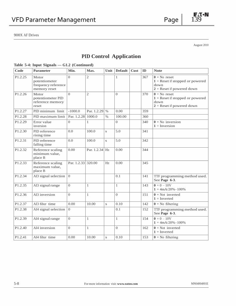
VFD Parameter Management Page 139
9000X AF Drives
August 2010
PID Control Application
Table 5-4: Input Signals — G1.2 (Continued)
Code Parameter Min. Max. Unit Default Cust ID Note
P1.2.25 Motor potentiometer frequency reference memory reset
0 2 1 367 0 = No reset 1 = Reset if stopped or powered down 2 = Reset if powered down
P1.2.26 Motor potentiometer PID reference memory reset
0 2 0 370 0 = No reset 1 = Reset if stopped or powered down 2 = Reset if powered down
P1.2.27 PID minimum limit -1000.0 Par. 1.2.29 % 0.00 359 P1.2.28 PID maximum limit Par. 1.2.28 1000.0 % 100.00 360 P1.2.29 Error value
inversion 0 1 0 340 0 = No inversion
1 = Inversion
P1.2.30 PID reference rising time
0.0 100.0 s 5.0 341
P1.2.31 PID reference falling time
0.0 100.0 s 5.0 342
P1.2.32 Reference scaling minimum value, place B
0.00 Par. 1.2.34 Hz 0.00 344
P1.2.33 Reference scaling maximum value, place B
Par. 1.2.33 320.00 Hz 0.00 345
P1.2.34 AI3 signal selection 0 0.1 141 TTF programming method used. See Page 6-3.
P1.2.35 AI3 signal range 0 1 1 143 0 = 0 – 10V 1 = 4mA/20%–100%
P1.2.36 AI3 inversion 0 1 0 151 0 = Not inverted 1 = Inverted
P1.2.37 AI3 filter time 0.00 10.00 s 0.10 142 0 = No filtering
P1.2.38 AI4 signal selection 0 0.1 152 TTF programming method used. See Page 6-3.
P1.2.39 AI4 signal range 0 1 1 154 0 = 0 – 10V 1 = 4mA/20%–100%
P1.2.40 AI4 inversion 0 1 0 162 0 = Not inverted 1 = Inverted
P1.2.41 AI4 filter time 0.00 10.00 s 0.10 153 0 = No filtering
5-8 For more information visit: www.eaton.com MN04004001E

VFD Parameter Management Page 140
9000X AF Drives
August 2010
PID Control Application
Output Signals (Control Keypad: Menu M1 ➔ G1.3)
Table 5-5: Output Signals — G1.3
Code Parameter Min. Max. Unit Default Cust ID Note
P1.3.1 Analog output 1 signal selection
0 A.1 464 TTF programming method used. See Page 6-3.
P1.3.2 Analog output function
0 14 1 307 0 = Not used 1 = Output freq. (0 – fmax) 2 = Freq. reference (0 – fmax) 3 = Motor speed (0 – Motor nominal speed)
4 = Motor current (0 – InMotor) 5 = Motor torque (0 – TnMotor) 6 = Motor power (0 – PnMotor) 7 = Motor voltage (0 – UnMotor) 8 = DC-Bus volt (0 – 1000V) 9 = PID controller ref. value 10 = PID contr. act. value 1 11 = PID contr. act. value 2 12 = PID contr. error value 13 = PID controller output 14 = PT100 temperature
P1.3.3 Analog output filter time
0.00 10.00 s 1.00 308 0 = No filtering
P1.3.4 Analog output inversion
0 1 0 309 0 = Not inverted 1 = Inverted
P1.3.5 Analog output minimum
0 1 0 310 0 = 0 mA 1 = 4 mA
P1.3.6 Analog output scale 10 1000 % 100 311 P1.3.7 Digital output 1
function 0 23 1 312 0 = Not used
1 = Ready 2 = Run 3 = Fault 4 = Fault inverted 5 = FC overheat warning 6 = Ext. fault or warning 7 = Ref. fault or warning 8 = Warning 9 = Reversed 10 = Preset speed 1 11 = At speed 12 = Mot. regulator active 13 = OP freq. limit superv.1 14 = OP freq.limit superv.2 15 = Torque limit superv. 16 = Ref. limit supervision 17 = External brake control 18 = Remote Control Active 19 = FC temp. limit superv. 20 = Unrequested direction 21 = Ext. brake control inv. 22 = Thermistor fault/warn. 23 = Fieldbus input data
P1.3.8 Relay output 1 function
0 23 2 313 Same as parameter 1.3.7
MN04004001E For more information visit: www.eaton.com 5-9

VFD Parameter Management Page 141
9000X AF Drives
August 2010
PID Control Application
Table 5-5: Output Signals — G1.3 (Continued)
Code Parameter Min. Max. Unit Default Cust ID Note
P1.3.9 Relay output 2 function
0 23 3 314 Same as parameter 1.3.7
P1.3.10 Output frequency limit 1 supervision
0 2 0 315 0 = No limit 1 = Low limit supervision 2 = High limit supervision
P1.3.11 Output frequency limit 1; Supervised value
0.00 Par. 1.1.2 Hz 0.00 316
P1.3.12 Output frequency limit 2 supervision
0 2 0 346 0 = No limit 1 = Low limit supervision 2 = High limit supervision
P1.3.13 Output frequency limit 2; Supervised value
0.00 Par. 1.1.2 Hz 0.00 347
P1.3.14 Torque limit supervision
0 2 0 348 0 = Not used 1 = Low limit supervision 2 = High limit supervision
P1.3.15 Torque limit supervision value
0.0 300.0 % 100.0 349
P1.3.16 Reference limit supervision
0 2 0 350 0 = Not used 1 = Low limit 2 = High limit
P1.3.17 Reference limit supervision value
0.00 Par. 1.1.2 Hz 0.00 351
P1.3.18 External brake-off delay
0.0 100.0 s 0.5 352
P1.3.19 External brake-on delay
0.0 100.0 s 1.5 353
P1.3.20 FC temperature supervision
0 2 0 354 0 = Not used 1 = Low limit 2 = High limit
P1.3.21 FC temperature supervised value
-10 75 °C 40 355
P1.3.22 Analog output 2 signal selection
0 0.1 471 TTF programming method used. See Page 6-3.
P1.3.23 Analog output 2 function
0 13 4 472 Same as parameter 1.3.2
P1.3.24 Analog output 2 filter time
0.00 10.00 s 1.00 473 0 = No filtering
P1.3.25 Analog output 2 inversion
0 1 0 474 0 = Not inverted 1 = Inverted
P1.3.26 Analog output 2 minimum
0 1 0 475 0 = 0 mA 1 = 4 mA
P1.3.27 Analog output 2 scaling
10 1000 % 100 476
5-10 For more information visit: www.eaton.com MN04004001E

VFD Parameter Management Page 142
9000X AF Drives
August 2010
PID Control Application
Drive Control Parameters (Control Keypad: Menu M1 ➔ G1.4)
Table 5-6: Drive Control Parameters — G1.4
Code Parameter Min. Max. Unit Default Cust ID Note
P1.4.1 Ramp 1 shape 0.0 10.0 s 0.0 500 0 = Linear >0 = S-curve ramp time
P1.4.2 Ramp 2 shape 0.0 10.0 s 0.0 501 0 = Linear >0 = S-curve ramp time
P1.4.3 Acceleration time 2 0.1 3000.0 s 0.1 502 P1.4.4 Deceleration time 2 0.1 3000.0 s 0.1 503 P1.4.5 Brake chopper 0 4 0 504 0 = Not used
1 = Used when running 2 = External brake chopper 3 = Used when stopped/running 4 = Used when running (no testing)
P1.4.6 Start function 0 1 0 505 0 = Ramp 1 = Flying start
P1.4.7 Stop function 0 3 1 506 0 = Coasting 1 = Ramp 2 = Ramp+Run enable coast 3 = Coast+Run enable ramp
P1.4.8 DC braking current 0.4 x IH 2 x IH A IH 507 P1.4.9 DC braking time
at stop 0.00 600.00 s 0.00 508 0 = DC brake is off at stop
P14.10 Frequency to start DC braking during ramp stop
0.10 10.00 Hz 1.50 515
P1.4.11 DC braking time at start
0.00 600.00 s 0.00 516 0 = DC brake is off at start
P1.4.12 Flux brake 0 1 0 520 0 = Off 1 = On
P1.4.13 Flux braking current 0.4 x IH 2 x IH A IH 519
Skip Frequency Parameters (Control Keypad: Menu M1 ➔ G1.5)
Table 5-7: Skip Frequency Parameters — G1.5
Code Parameter Min. Max. Unit Default Cust ID Note P1.5.1 Skip frequency
range 1 low limit 0.00 par.
1.5.2 Hz 0.00 509
P1.5.2 Skip frequency range 1 high limit
0.00 par. 1.1.2
Hz 0.0 510 0 = Skip frequency range 1 not used
P1.5.3 Skip frequency range 2 low limit
0.00 par. 1.5.2
Hz 0.00 511
P1.5.4 Skip frequency range 2 high limit
0.00 par. 1.1.2
Hz 0.0 512 0 = Skip frequency range 2 not used
P1.5.5 Skip frequency range 3 low limit
0.00 par. 1.5.2
Hz 0.00 513
P1.5.6 Skip frequency range 3 high limit
0.00 par. 1.1.2
Hz 0.0 514 0 = Skip frequency range 3 not used
P1.5.7 Skip frequency acc./dec. ramp
0.1 10.0 1.0 518
MN04004001E For more information visit: www.eaton.com 5-11

VFD Parameter Management Page 143
9000X AF Drives
August 2010
PID Control Application
Motor Control Parameters (Control Keypad: Menu M1 ➔ G1.6)
Table 5-8: Motor Control Parameters — G1.6
Code Parameter Min. Max. Unit Default Cust ID Note
P1.6.1 Motor control mode 0 1/6 0 600 SVX: 0 = Frequency control 1 = Speed control
Additionally for SPX: 2 = Torque control 3 = Closed loop speed ctrl 4 = Closed loop torque ctrl
P1.6.2 V/Hz optimization 0 1 0 109 0 = Not used 1 = Automatic torque boost
P1.6.3 V/Hz ratio selection 0 3 0 108 0 = Linear 1 = Squared 2 = Programmable 3 = Linear with flux optim.
P1.6.4 Field weakening point
8.00 320.00 Hz 60.00 602
P1.6.5 Voltage at field weakening point
10.00 200.00 % 100.00 603 n% x Unmot
P1.6.6 V/Hz curve midpoint frequency
0.00 Par. 1.6.4 Hz 60.00 604 V/Hz midfreq
P1.6.7 V/Hz curve midpoint voltage
0.00 100.00 % 100.00 605 n% x Unmot
Parameter max. value = par. 1.6.5 P1.6.8 Output voltage at
zero frequency 0.00 40.00 % 1.30 606 n% x Unmot
P1.6.9 Switching frequency 1.0 Varies kHz Varies 601 See Table 8-12 on Page 8-57 for exact values
P1.6.10 Overvoltage controller
0 2 1 607 0 = Not used 1 = Used (no ramping) 2 = Used (ramping)
P1.6.11 Undervoltage controller
0 1 1 608 0 = Not used 1 = Used
P1.6.12 Load Drooping 0.00 100.00 0.00 620 Drooping % of nominal speed at nominal torque
P1.6.13 Identification 0 1 0 631 0 = Not used 1 = Used
5-12 For more information visit: www.eaton.com MN04004001E

VFD Parameter Management Page 144
9000X AF Drives
August 2010
PID Control Application
Table 5-8: Motor Control Parameters — G1.6 (Continued)
Code Parameter Min. Max. Unit Default Cust ID Note Closed Loop parameter group 1.6.14 (SPX only)
P1.6.14.1 Magnetizing current 0.00 100.00 A 0.00 612 P1.6.14.2 Speed control P gain 0 1000 30 613 P1.6.14.3 Speed control I time 0.0 500.0 ms 30.0 614 P1.6.14.4 Load drooping 0.00 100.00 % 0.00 620 P1.6.14.5 Acceleration
compensation 0.00 300.00 s 0.00 626
P1.6.14.6 Slip adjust 0 500 % 100 619 P1.6.14.7 Magnetizing current
at start MotCurr Min
MotCurr Max
A 0.00 627
P1.6.14.8 Magnetizing time at start
0.0 600.0 s 0.0 628
P1.6.14.9 0-speed time at start 0 32000 ms 100 615 P1.6.14.10 0-speed time at stop 0 32000 ms 100 616 P1.6.14.11 Start-up torque 0 3 0 621 0 = Not used
1 = Torque memory 2 = Torque reference 3 = Start-up torque fwd/rev
P1.6.14.12 Start-up torque FWD -300.0 300.0 s 0.0 633 P1.6.14.13 Start-up torque REV -300.0 300.0 s 0.0 634 P1.6.14.15 Encoder filter time 0 1000 ms 0 618 P1.6.14.17 Current control
P gain 0.00 100.00 % 40.00 617
MN04004001E For more information visit: www.eaton.com 5-13

VFD Parameter Management Page 145
9000X AF Drives
August 2010
PID Control Application
Protections (Control Keypad: Menu M1 ➔ G1.7)
Table 5-9: Protections — G1.7
Code Parameter Min. Max. Unit Default Cust ID Note
P1.7.1 Response to reference fault
0 5 0 700 0 = No response 1 = Warning 2 = Warning+Previous Freq. 3 = Wrng+PresetFreq 1.7.2 4 = Fault.stop acc. to 1.4.7 5 = Fault.stop by coasting
P1.7.2 4mA reference fault frequency
0.00 Par. 1.1.2 Hz 0.00 728
P1.7.3 Response to external fault
0 3 2 701 0 = No response 1 = Warning 2 = Fault.stop acc. to 1.4.7 3 = Fault.stop by coasting
P1.7.4 Input phase supervision
0 3 3 730
P1.7.5 Response to undervoltage fault
1 3 0 727
P1.7.6 Output phase supervision
0 3 2 702
P1.7.7 Earth fault protection
0 3 2 703
P1.7.8 Thermal protection of the motor
0 3 2 704
P1.7.9 Motor ambient temperature factor
-100.0 100.0 % 0.0 705
P1.7.10 Motor cooling factor at zero speed
0.0 150.0 % 40.0 706
P1.7.11 Motor thermal time constant
1 200 min 45 707
P1.7.12 Motor duty cycle 0 100 % 100 708 P1.7.13 Stall protection 0 3 1 709 0 = No response
1 = Warning 2 = Fault.stop acc. to 1.4.7 3 = Fault.stop by coasting
P1.7.14 Stall current 0.1 InMotor x 2
A IL 710
P1.7.15 Stall time limit 1.00 120.00 s 15.00 711 P1.7.16 Stall frequency limit 1.0 Par. 1.1.2 Hz 25.0 712 P1.7.17 Underload
protection 0 3 0 713 0 = No response
1 = Warning 2 = Fault.stop acc. to 1.4.7 3 = Fault.stop by coasting
P1.7.18 Field weakening area load
10 150 % 50 714
P1.7.19 Zero frequency load 5.0 150.0 % 10.0 715 P1.7.20 Underload
protection time limit
2 600 s 20 716
5-14 For more information visit: www.eaton.com MN04004001E

VFD Parameter Management Page 146
9000X AF Drives
August 2010
PID Control Application
Protections — G1.7 (Continued)
Code Parameter Min. Max. Unit Default Cust ID Note
P1.7.21 Response to thermistor fault
0 3 2 732 0 = No response 1 = Warning 2 = Fault.stop acc. to 1.4.7 3 = Fault.stop by coasting
P1.7.22 Response to fieldbus fault
0 3 2 733 See P1.7.21
P1.7.23 Response to slot fault
0 3 2 734 See P1.7.21
P1.7.24 No. of PT100 inputs 0 3 0 739 P1.7.25 Response to PT100
fault 0 3 2 740 0 = No response
1 = Warning 2 = Fault.stop acc. to 1.4.7 3 = Fault.stop by coasting
P1.7.26 PT100 warning limit -30.0 200.0 Cº 120.0 741 P1.7.27 PT100 fault limit -30.0 200.0 Cº 130.0 742
Autorestart Parameters (Control Keypad: Menu M1 ➔ G1.8)
Table 5-10: Autorestart Parameters — G1.8
Code Parameter Min. Max. Unit Default Cust ID Note
P1.8.1 Wait time 0.10 10.00 s 0.50 717 P1.8.2 Trial time 0.00 60.00 s 30.00 718 P1.8.3 Start function 0 2 0 719 0 = Ramp
1 = Flying start 2 = According to par. 1.4.6
P1.8.4 Number of tries after undervoltage trip
0 10 0 720
P1.8.5 Number of tries after overvoltage trip
0 10 0 721
P1.8.6 Number of tries after overcurrent trip
0 3 0 722
P1.8.7 Number of tries after reference trip
0 10 0 723
P1.8.8 Number of tries after motor temp fault trip
0 10 0 726
P1.8.9 Number of tries after external fault trip
0 10 0 725
P1.8.10 Number of tries after underload fault trip
0 10 0 738
MN04004001E For more information visit: www.eaton.com 5-15

VFD Parameter Management Page 147
9000X AF Drives
August 2010
PID Control Application
Keypad Control (Control Keypad: Menu M2)
The parameters for the selection of control place and direction on the keypad are listed
below. See the Keypad control menu in the 9000X AF Drives User Manual.
Table 5-11: Keypad Control Parameters — M2
Code Parameter Min. Max. Unit Default Cust ID Note
P2.1 Control place 0 3 0 1685 0 = Keypad L/R 1 = Local 2 = Remote 3 = I/O force
R2.2 Keypad reference Par. 1.1.1
Par.1.1.2 Hz
P2.3 Direction (on keypad)
0 1 0 123 0 = Forward 1 = Reverse
R2.4 PID reference 0.00 100.00 % 50.00 R2.5 PID reference 2 0.00 100.00 % 0.00 P2.6 Stop button 0 1 1 114 0 = Limited function of Stop
button 1 = Stop button always enabled
P2.7 Operate menu hide 0 1 1 0 = Yes 1 = No
System Menu (Control Keypad: Menu M5)
For parameters and functions related to the general use of the drive, such as application
and language selection, customized parameter sets or information about the hardware and
software, see Chapter 5 in the 9000X AF Drives User Manual.
Expander Boards (Control Keypad: Menu M6)
The M6 menu shows the expander and option boards attached to the control board and
board-related information. For more information, see Chapter 5 in the 9000X AF Drives
User Manual.
Note: In local and remote control, the control mode is determined by DIN6 unless the PID is
selected as the reference.
5-16 For more information visit: www.eaton.com MN04004001E

VFD Parameter Management Page 148
9000X AF Drives
August 2010
Chapter 6 — Multi-Purpose Control Application Introduction
Select the Multi-Purpose Control Application in menu M5. See Chapter 5 of the 9000X AF
Drives User Manual.
Multi-purpose control application provides a wide range of parameters for controlling
motors. It can be used for various kinds of different processes, where wide flexibility of I/O
signals is needed and PID-control is not necessary (if you need PID-control functions, use
PID-control Application or Pump and Fan Control Application).
The frequency reference can be selected e.g. from the analog inputs, joystick control, motor
potentiometer and from a mathematical function of the analog inputs. There are parameters
also for Fieldbus communication. Multi-step speeds and jogging speed can also be selected if
digital inputs are programmed for these functions.
● The digital inputs and all the outputs are freely programmable and the application
supports all I/O-boards
Additional functions:
● Analog input signal range selection
● Two frequency limit supervisions
● Torque limit supervision
● Reference limit supervision
● Second ramps and S-shape ramp programming
● Programmable Start/Stop and Reverse logic
● DC-brake at start and stop
● Three skip frequency areas
● Programmable V/Hz curve and switching frequency
● Autorestart
● Motor thermal and stall protection: fully programmable; off, warning, fault
● Motor underload protection
● Input and output phase supervision
● Joystick hysteresis
● Possibility to connect the FB Process data to any parameter and some monitoring values
The parameters of the Multi-Purpose Control Application are explained in Chapter 8 of this
manual. The explanations are arranged according to the individual ID number of the parameter.
MN04004001E For more information visit: www.eaton.com 6-1

VFD Parameter Management Page 149
9000X AF Drives
August 2010
Control I/O
Reference potentiometer 1 – 10 kW
Multi-Purpose Control Application Table 6-1: Multi-Purpose Control Application Default I/O Configuration and Connection Example
Terminal Signal Description
OPTA1
1 +10Vref Reference output Voltage for potentiometer, etc.
2 AI1+ Analog input, voltage range 0 – 10V DC
Voltage input frequency reference
3 AI1- I/O Ground Ground for reference and controls
4 AI2+ Analog input, current range Current input frequency reference
5 AI2- 0 – 20 mA
6 +24V Control voltage output Voltage for switches, etc. max 0.1A
7 GND I/O ground Ground for reference and controls
8 DIN1 Start forward (programmable)
9 DIN2 Start reverse (programmable)
Contact closed = start forward
Contact closed = start reverse
10 DIN3 Fault reset (programmable) Contact closed = fault reset
11 CMA Common for DIN1 – DIN3 Connect to GND or +24V
12 +24V Control voltage output Voltage for switches (see terminal 6)
13 GND I/O ground Ground for reference and controls
14 DIN4 Jog speed selection
(programmable)
15 DIN5 External fault
(programmable)
16 DIN6 Accel./decel. time select (programmable)
Contact closed = jog speed active
Contact open = no fault Contact closed = fault
Contact open = P1.1.3, P1.1.4 in use Contact closed = P1.4.3, P1.4.4 in use
17 CMB Common for DIN4 – DIN6 Connect to GND or +24V
mA 18 AOA1+ Output frequency Programmable
READY 19 AOA1- Analog output Range 0 – 20 mA, RL, max. 500W
20 DOA1 Digital output READY
Programmable Open collector, I ≤ 50 mA, V ≤ 48V DC
OPTA2
21 RO1 Relay output 1 Programmable
RUN 22 RO1
23 RO1
RUN
24 RO2 Relay output 2 Programmable
220V
AC
25 RO2
26 RO2
FAULT
Note: For more information on jumper selections, see the 9000X AF Drives User
Manual, Chapter 4. Jumper Block X3: CMA and CMB Grounding
CMB connected to GND
CMA connected to GND CMB isolated from GND
CMA isolated from GND
CMB and CMA internally connected together, isolated from GND

VFD Parameter Management Page 150
9000X AF Drives
August 2010
Multi-Purpose Control Application
“Terminal To Function” (TTF) Programming Principle
The programming principle of the input and output signals in the Multi-Purpose Control
Application as well as in the Pump and Fan Control Application (and partly in the other
applications) is different compared to the conventional method used in other SVX applications.
In the conventional programming method, Function To Terminal programming method (FTT),
you have a fixed input or output that you define a certain function for. The applications
mentioned above, however, use the Terminal To Function programming method (TTF) in
which the programming process is carried out the other way round: Functions appear as
parameters which the operator defines a certain input/output. See Caution on Page 6-4.
Defining an Input/Output for a Certain Function on Keypad
Connecting a certain input or output with a certain function (parameter) is done by giving the
parameter an appropriate value. The value is formed of the Board slot on the SVX control
board (see 9000X AF Drives User Manual, Chapter 4) and the respective signal number as
shown in Figure 6-1.
Function Name P1.3.3.7
AI Ref Faul/Warn
DigOUT: B.1
Terminal Type Slot Terminal Number
Figure 6-1: Defining Input/Output — Function
Example: You want to connect the digital output function Reference fault/warning (P1.3.3.7) to
the digital output DO1 on the basic board OPTA1 (see 9000X AF Drives User Manual, Chapter 4).
First find the P1.3.3.7 on the keypad. Press the Menu button right once to enter the edit mode.
On the value line, you will see the terminal type on the left (DigIN, DigOUT, An.IN, An.OUT)
and on the right, the present input/output the function is connected to (B.3. A.2 etc.), or if not
connected, a value (0.#).
When the value is blinking, hold down the Browser button up or down to find the desired
board slot and signal number. The program will scroll the board slots starting from 0 and
proceeding from A to E and the I/O selection from 1 to 10.
Once you have set the desired value, press the Enter button once to confirm the change.
See Figure 6-2.
P1..3.3.7
AI Ref Faul/Warn P1.3.3.7
AI Ref Faul/Warn P1.3.3.7
AI Ref Faul/Warn
DigOUT: 0.0 DigOUT: 0.0 DigOUT: A.1
Figure 6-2: Defining Input/Output — Values

VFD Parameter Management Page 151
9000X AF Drives
August 2010
Multi-Purpose Control Application
Defining a Terminal for a Certain Function with 9000X Drive Programming Tool
If you use the 9000X Drive Programming Tool for parametrizing you will have to establish the
connection between the function and input/output in the same way as with the control panel.
Just pick the address code from the drop-down menu in the Value column (see Figure 6-3).
Figure 6-3: Screenshot of 9000X Drive Programming Tool; Entering the Address Code
CAUTION
Be ABSOLUTELY sure not to connect two functions to one and
same output in order to avoid function overruns and to ensure
flawless operation.
Notice
The inputs, unlike the outputs, cannot be changed in RUN state.
Defining Unused Inputs/Outputs
All unused inputs and outputs must be given the board slot value 0 and the value 1 also for
the terminal number. The value 0.0 is also the default value for most of the functions.
However. if you want to use the values of a digital input signal for e.g. testing purposes only.
you can set the board slot value to 0 and the terminal number to any number between 2…10
to place the input to a TRUE state. In other words, the value 1 corresponds to “open contact”
and values 2 to 10 to closed contact.
In case of analog inputs, giving the value 1 for the terminal number corresponds to 0%, value
2 corresponds to 20% and any value between 3 and 10 corresponds to 100%.
6-4 For more information visit: www.eaton.com MN04004001E

VFD Parameter Management Page 152
9000X AF Drives
August 2010
Parameter Lists
Multi-Purpose Control Application
On the next pages you will find the lists of parameters within the respective parameter
groups. The parameter descriptions are given in Chapter 8.
Column explanations:
Code = Location indication on the keypad; Shows the operator the present
parameter number
Parameter = Name of parameter
Min. = Minimum value of parameter
Max. = Maximum value of parameter
Unit = Unit of parameter value; Given if available
Default = Value preset by factory
Cust
ID
=
=
User’s customized setting
ID number of the parameter for reference to Chapter 8
= Parameter value can only be changed when the drive is stopped = Programmed using terminal to function (TTF) method. See Page 6-
Monitoring Values (Control Keypad: Menu M8)
The monitoring values are the actual values of parameters and signals as well as statuses
and measurements. Monitoring values cannot be edited.
See 9000X AF Drives User Manual, Chapter 5 for more information.
Table 6-2: Monitoring Values, SPX Drives
Code Parameter Unit ID Description
V7.1 Output Frequency Hz 1 Output frequency to motor
V7.2 FreqRreference Hz 25 Frequency reference to motor control
V7.3 Motor Speed Rpm rpm 2 Motor speed in rpm
V7.4 Motor Current A 3 V7.5 Motor Torque % 4 In % of nominal torque
V7.6 Motor Power % 5 Motor shaft power in %
V7.7 Motor Voltage V 6 V7.8 DC-Bus Voltage V 7 V7.9 Unit Temperature ∞C 8 Heatsink temperature
V7.10 MotorTemperature % 9 Calculated motor temperature
V7.11 Analog Input 1 V 13 AI1
V7.12 Analog Input 2 mA 14 AI2
V7.13 DIN1, DIN2, DIN3 15 Digital input status
V7.14 DIN4, DIN5, DIN6 16 Digital input status
V7.15 Analog lout mA 26 AO1
V7.16 Analog Input 3 mA 27 AI3
V7.17 Analog Input 4 mA 14 AI4
V7.18 Torque Reference % 18 V7.19 PT100 Temp. C° 42 Max PT100 Temp
MN04004001E For more information visit: www.eaton.com 6-5

VFD Parameter Management Page 153
9000X AF Drives
August 2010
Multi-Purpose Control Application Table 6-2: Monitoring Values, SPX Drives (Continued)
Code Parameter Unit ID Description
M7.20 Multimonitor Displays three selectable monitor values
G7.21 Monitor 2 V7.21.1 Current A 1113 Unfiltered Motor Current
V7.21.2 Torque % 1125 Unfiltered Motor Torque
V7.21.3 DC Voltage V 44 Unfiltered DC Link Voltage
V7.21.4 Status Word 43 Application Status Word
V7.21.5 Last Active Fault 37 V7.21.6 On Time Hours h 10 Power On Trip Counter
V7.21.7 DIN Status Word 56 DIN 1–6 (Low b) and OPT-B1 or B9 DIN (High b)
V7.21.8 Motor Current FB A 45 Motor current to 1 decimal place
V7.21.9 U Phase Current A 39 V7.21.10 V Phase Current A 40 V7.21.11 W Phase Current A 41 V7.21.12 PT100 Temp. In1 °C 50 V7.21.13 PT100 Tem. In2 °C 51 V7.21.14 PT100 Tem. In3 °C 52 V7.21.15 PT100 Tem. In4 °C 69 V7.21.16 PT100 Tem. In5 °C 70 V7.21.17 PT100 Tem. In6 °C 71
Operate Menu-M8
The Operate Menu provides an easy-to-use method of viewing key numerical Monitoring Menu Items. It also allows the setting of the Keypad frequency or torque reference. See Chapter 5 of the 9000X User Manual for more information.
Table 6-3: Operate Menu Items
Code Parameter Unit Description
O1 Output Frequency Hz Output frequency to motor
O2 FreqRreference Hz Frequency reference to motor control
O3 Motor Speed rpm Motor speed in rpm
O4 Motor Current A O5 Motor Torque % In % of nominal motor torque
O6 Motor Power % Motor shaft power in %
O7 Motor Voltage V O8 DC-Bus Voltage V O9 Unit Temperature °C Heatsink temperature
O10 MotorTemperature % Calculated motor temperature
O11 U Phase Current A Motor phase current
O12 V Phase Current A Motor phase current
O13 W Phase Current A Motor phase current
O14 Torque Reference % Torque Ref in Torque Control Mode
R1 Keypad Reference Hz Set keypad frequency reference
R4 Torque Reference Hz Set keypad torque reference
6-6 For more information visit: www.eaton.com MN04004001E

VFD Parameter Management Page 154
9000X AF Drives
August 2010
Multi-Purpose Control Application
Fieldbus Control and Status
The Multipurpose Application has more functionality with the fieldbus control. Bits 3 through
7 of the Fixed Control Word can be used to set digital outputs. The digital inputs are
monitored with the DIN Status Word (ID 56). The mode of the control is monitored with the
Application Status Word (ID 43), Bits 4, 8, 9, and 10.
Table 6-4: Fixed Control Word
Bit Function Note
B0 FB_Run B1 FB_Reverse B2 FB_Fault_Reset B3 FB_D01 See Parameter 1.3.3.24
B4 FB_D02 See Parameter 1.3.3.25
B5 FB_D03 See Parameter 1.3.3.26
B6 FB_D04 See Parameter 1.3.3.27
B7 FB_D05 See Parameter 1.3.3.28
B8 Not Used B9 Not Used B10 Not Used B11 FB_WD_Pulse See Parameter 1.7.32
B12 Not Used B13 Not Used B14 Not Used B15 FB_Fault_Monitor (internal) Select Comm cards
Table 6-5: Status Word
Code General Status Word Application Status Word
B0 MC_Ready Not used
B1 MC_Run MC_Ready
B2 MC_Reverse MC_Run
B3 MC_Fault MC_Fault
B4 MC_Warning FB_Ref_Active
B5 MC_AtSpeed Not used
B6 MC_ZeroSpeed RunEnable
B7 MC_FluxReady MC_Warning
B8 MC_TCSpeedLimit Active Panel I/O Control Indicator
B9 MC_DetectedEncoderDirection Panel Panel Control Indicator
B10 MC_UVFastStop Panel Fieldbus Control Indicator
B11 MC_DC_Brake MC_DC_Brake
B12 FB_Ref_Active RunRequest
B13 MC_StartDelay (not used) Motor Regulator Status not Zero
B14 Remote_Active External Brake Control
B15 FB_WD_Pulse Not used
MN04004001E For more information visit: www.eaton.com 6-7

VFD Parameter Management Page 155
9000X AF Drives
August 2010
Multi-Purpose Control Application
Basic Parameters (Control Keypad: Menu M1 ➔ G1.1)
Table 6-6: Basic Parameters — G1.1
Code Parameter Min. Max. Unit Default ID Note
P1.1.1 Min frequency 0.00 Par. 1.1.2 Hz 0.00 101 P1.1.2 Max frequency Par. 1.1.1 320.00 Hz 60.00 102 NOTE: If fmax > than the motor
synchronous speed, check suitability for motor and drive system.
P1.1.3 Acceleration time 1 0.1 3000.0 s 3.0 103 P1.1.4 Deceleration time 1 0.1 3000.0 s 3.0 104 P1.1.5 Current limit 0.1 x IH 2 x IH A IL 107 IH is the nominal current rating of
the 9000X inverter.
P1.1.6 Nominal voltage of the motor
180 690 V SVX-2: 230V SVX-4: 460V SVX-5: 575V
110 Motor nameplate value.
P1.1.7 Nominal frequency of the motor
0.00 320.00 Hz 60.00 111 Motor nameplate value.
P1.1.8 Nominal speed of the motor
0 65000 rpm 1720 112 Motor nameplate value.
P1.1.9 Nominal current of the motor
0.1 x IH 2 x IH A IH 113 Check the rating plate of the motor.
P1.1.10 Power Factor 0.30 1.00 0.85 120 Check the rating plate of the motor.
P1.1.11 Local control place 1 3 2 171 1 = I/O Terminal 2 = Keypad 3 = Fieldbus
P1.1.12 Remote control place
1 3 1 172 1 = I/O Terminal 2 = Keypad 3 = Fieldbus
P1.1.13 Local reference 0 15 8 173 0 = AI1 1 = AI2 2 = AI1+AI2 3 = AI1-AI2 4 = AI2-AI1 5 = AI1xAI2 6 = AI1 Joystick 7 = AI2 Joystick 8 = Keypad 9 = Fieldbus 10 = Motor potentiometer 11 = AI1, AI2 minimum 12 = AI1, AI2 maximum 13 = Max frequency 14 = AI1/AI2 selection 15 = Encoder A1
6-8 For more information visit: www.eaton.com MN04004001E
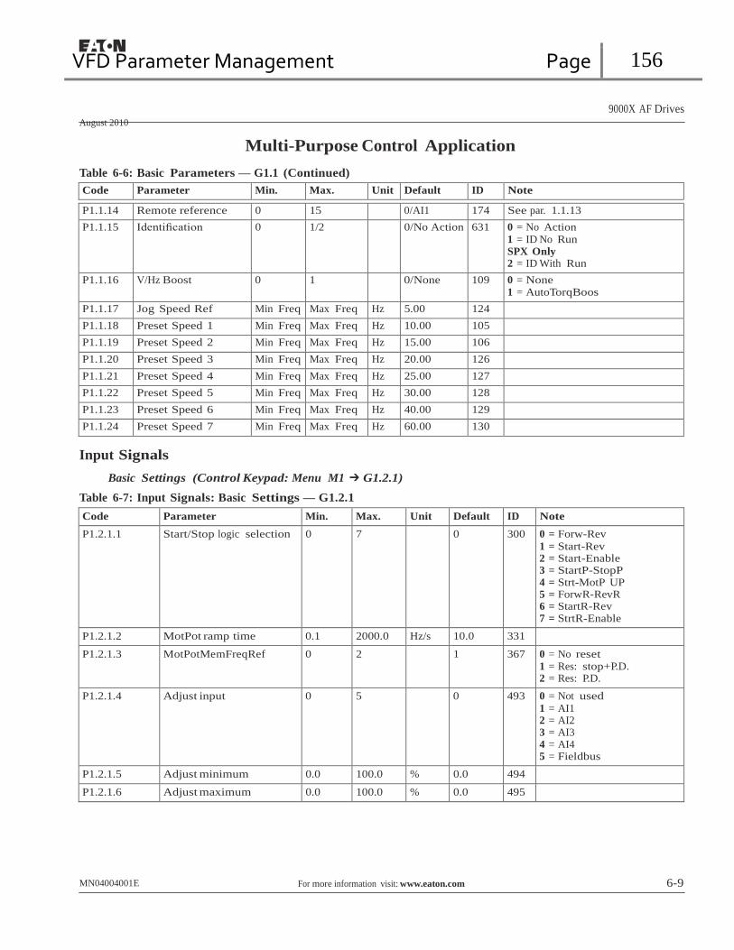
VFD Parameter Management Page 156
9000X AF Drives
August 2010
Multi-Purpose Control Application
Table 6-6: Basic Parameters — G1.1 (Continued)
Code Parameter Min. Max. Unit Default ID Note
P1.1.14 Remote reference 0 15 0/AI1 174 See par. 1.1.13
P1.1.15 Identification 0 1/2 0/No Action 631 0 = No Action 1 = ID No Run SPX Only 2 = ID With Run
P1.1.16 V/Hz Boost 0 1 0/None 109 0 = None 1 = AutoTorqBoos
P1.1.17 Jog Speed Ref Min Freq Max Freq Hz 5.00 124 P1.1.18 Preset Speed 1 Min Freq Max Freq Hz 10.00 105 P1.1.19 Preset Speed 2 Min Freq Max Freq Hz 15.00 106 P1.1.20 Preset Speed 3 Min Freq Max Freq Hz 20.00 126 P1.1.21 Preset Speed 4 Min Freq Max Freq Hz 25.00 127 P1.1.22 Preset Speed 5 Min Freq Max Freq Hz 30.00 128 P1.1.23 Preset Speed 6 Min Freq Max Freq Hz 40.00 129 P1.1.24 Preset Speed 7 Min Freq Max Freq Hz 60.00 130
Input Signals
Basic Settings (Control Keypad: Menu M1 ➔ G1.2.1)
Table 6-7: Input Signals: Basic Settings — G1.2.1
Code Parameter Min. Max. Unit Default ID Note
P1.2.1.1 Start/Stop logic selection 0 7 0 300 0 = Forw-Rev
1 = Start-Rev 2 = Start-Enable 3 = StartP-StopP 4 = Strt-MotP UP 5 = ForwR-RevR 6 = StartR-Rev 7 = StrtR-Enable
P1.2.1.2 MotPot ramp time 0.1 2000.0 Hz/s 10.0 331
P1.2.1.3 MotPotMemFreqRef 0 2 1 367 0 = No reset 1 = Res: stop+P.D. 2 = Res: P.D.
P1.2.1.4 Adjust input 0 5 0 493 0 = Not used
1 = AI1 2 = AI2 3 = AI3 4 = AI4 5 = Fieldbus
P1.2.1.5 Adjust minimum 0.0 100.0 % 0.0 494
P1.2.1.6 Adjust maximum 0.0 100.0 % 0.0 495
MN04004001E For more information visit: www.eaton.com 6-9

VFD Parameter Management Page 157
9000X AF Drives
August 2010
Multi-Purpose Control Application
Analog Input 1 (Control Keypad: Menu M1 ➔ G1.2.2)
Table 6-8: Analog Input 1 Parameters — G1.2.2
Code Parameter Min. Max. Unit Default ID Note
P1.2.2.1 AI1 signal selection 0 A.1 377 TTF programming. See chapter 6.3
P1.2.2.2 AI1 filter time 0.00 10.00 s 0.10 324 0 = No filtering
P1.2.2.3 AI1 signal range 0 3 0 320 0 = 0–100%
1 = 4mA/20%–100% 2 = -10V...+10V 3 = Custom range
P1.2.2.4 AI1 custom minimum setting
-160.00 160.00 % 0.00 321
P1.2.2.5 AI1 custom maximum setting
-160.00 160.00 % 100.00 322
P1.2.2.6 AI1 reference scaling. minimum value
0.00 320.00 Hz 0.00 303 Selects the frequency that corresponds to the min. reference signal
P1.2.2.7 AI1 reference scaling. maximum value
0.00 320.00 Hz 0.00 304
P1.2.2.8 AI1 joystick hysteresis 0.00 20.00 % 0.00 384
P1.2.2.9 AI1 sleep limit 0.00 100.00 % 0.00 385
P1.2.2.10 AI1 sleep delay 0.00 320.00 s 0.00 386
P1.2.2.11 AI1 joystick offset -50.00 50.00 % 0.00 165
Remember to place jumpers of block X2 accordingly. See 9000X AF Drives User Manual, Chapter 4.
6-10 For more information visit: www.eaton.com MN04004001E

VFD Parameter Management Page 158
9000X AF Drives
August 2010
Multi-Purpose Control Application
Analog Input 2 (Control Keypad: Menu M1 ➔ G1.2.3)
Table 6-9: Analog Input 2 Parameters — G1.2.3
Code Parameter Min. Max. Unit Default Cust ID Note
P1.2.3.1 AI2 signal selection
0 A.2 388 TTF programming. See chapter 6.3
P1.2.3.2 AI2 filter time 0.00 10.00 s 0.10 329 0 = No filtering
P1.2.3.3 AI2 signal range 0 3 1 325 0 = 0–100% 1 = 4mA/20%–100% 2 = -10V...+10V
3 = Custom range
P1.2.3.4 AI2 custom minimum setting
-160.00 160.00 % 0.00 326
P1.2.3.5 AI2 custom maximum setting
-160.00 160.00 % 100.00 327
P1.2.3.6 AI2 reference scaling, minimum value
0.00 320.00 Hz 0.00 393 Selects the frequency that corresponds to the min. reference signal
P1.2.3.7 AI2 reference scaling, maximum value
0.00 320.00 Hz 0.00 394 Selects the frequency that corresponds to the max. reference signal
P1.2.3.8 AI2 joystick hysteresis
0.00 20.00 % 0.00 395 Dead zone for joystick input
P1.2.3.9 AI2 sleep limit 0.00 100.00 % 0.00 396 Drive goes to sleep mode if input is below this limit for set time.
P1.2.3.10 AI2 sleep delay 0.00 320.00 s 0.00 397
P1.2.3.11 AI2 joystick offset -50.00 50.00 % 0.00 166 Remember to place jumpers of block X2 accordingly. See 9000X AF Drives User Manual, Chapter 4.
Analog Input 3 (Control Keypad: Menu M1 ➔ G1.2.4)
Table 6-10: Analog Input 3 Parameters — G1.2.4
Code Parameter Min. Max. Unit Default Cust ID Note
P1.2.4.1 AI3 signal selection
0 0.1 141 TTF programming. See chapter 6.3
P1.2.4.2 AI3 filter time 0.00 10.00 s 0.10 142 0 = No filtering
P1.2.4.3 AI3 signal range 0 3 1 143 0 = 0–100%
1 = 4mA/20%–100% 2 = -10V...+10V 3 = Custom range
P1.2.4.4 AI3 custom minimum setting
-160.00 160.00 % 0.00 144
P1.2.4.5 AI3 custom maximum setting
-160.00 160.00 % 100.00 145
P1.2.4.6 AI3 signal inversion
0 1 0 151 0 = Not inverted
1 = Inverted
MN04004001E For more information visit: www.eaton.com 6-11
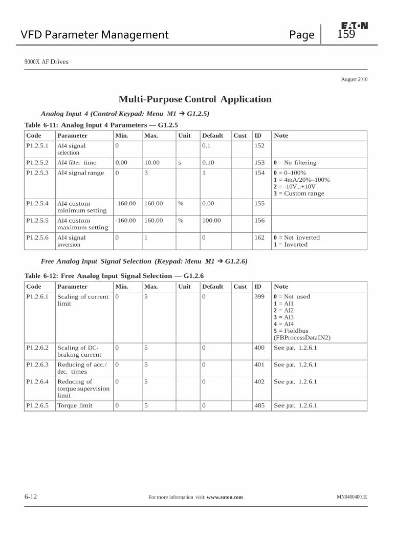
VFD Parameter Management Page 159
9000X AF Drives
August 2010
Multi-Purpose Control Application
Analog Input 4 (Control Keypad: Menu M1 ➔ G1.2.5)
Table 6-11: Analog Input 4 Parameters — G1.2.5
Code Parameter Min. Max. Unit Default Cust ID Note
P1.2.5.1 AI4 signal selection
0 0.1 152
P1.2.5.2 AI4 filter time 0.00 10.00 s 0.10 153 0 = No filtering
P1.2.5.3 AI4 signal range 0 3 1 154 0 = 0–100%
1 = 4mA/20%–100% 2 = -10V...+10V 3 = Custom range
P1.2.5.4 AI4 custom minimum setting
-160.00 160.00 % 0.00 155
P1.2.5.5 AI4 custom maximum setting
-160.00 160.00 % 100.00 156
P1.2.5.6 AI4 signal inversion
0 1 0 162 0 = Not inverted 1 = Inverted
Free Analog Input Signal Selection (Keypad: Menu M1 ➔ G1.2.6)
Table 6-12: Free Analog Input Signal Selection — G1.2.6
Code Parameter Min. Max. Unit Default Cust ID Note
P1.2.6.1 Scaling of current limit
0 5 0 399 0 = Not used 1 = AI1 2 = AI2 3 = AI3 4 = AI4 5 = Fieldbus (FBProcessDataIN2)
P1.2.6.2 Scaling of DC- braking current
0 5 0 400 See par. 1.2.6.1
P1.2.6.3 Reducing of acc./
dec. times 0 5 0 401 See par. 1.2.6.1
P1.2.6.4 Reducing of
torque supervision limit
0 5 0 402 See par. 1.2.6.1
P1.2.6.5 Torque limit 0 5 0 485 See par. 1.2.6.1
6-12 For more information visit: www.eaton.com MN04004001E

VFD Parameter Management Page 160
9000X AF Drives
August 2010
Multi-Purpose Control Application
Digital Inputs (Control Keypad: Menu M1 ➔ G1.2.7)
Table 6-13: Digital Input Signals — G1.2.7
Code Parameter Min. Max Default ID Note
P1.2.7.1 Start Signal 1 DigIN:0.1 DigIN:E.10 DigIN:A.1 403 See P1.2.1.1
P1.2.7.2 Start signal 2 DigIN:0.1 DigIN:E.10 DigIN:A.2 404 See P1.2.1.1
P1.2.7.3 Run Enable DigIN:0.1 DigIN:E.10 DigIN:0.2 407 Motor start enabled (cc)
P1.2.7.4 Reverse DigIN:0.1 DigIN:E.10 DigIN:0.1 412 Direction forward (oc)
Direction reverse (cc)
P1.2.7.5 Preset Speed 1 DigIN:0.1 DigIN:E.10 DigIN:0.1 419 See preset speeds in Basic Parameters (G2.1)
P1.2.7.6 Preset Speed 2 DigIN:0.1 DigIN:E.10 DigIN:0.1 420
P1.2.7.7 Preset Speed 3 DigIN:0.1 DigIN:E.10 DigIN:0.1 421
P1.2.7.8 Mot Pot Down DigIN:0.1 DigIN:E.10 DigIN:0.1 417 Mot.pot. reference decreases (cc)
P1.2.7.9 Mot Pot Up DigIN:0.1 DigIN:E.10 DigIN:0.1 418 Mot.pot. reference increases (cc)
P1.2.7.10 Fault Reset DigIN:0.1 DigIN:E.10 DigIN:A.3 414 All faults reset (cc)
P1.2.7.11 External Fault (close) DigIN:0.1 DigIN:E.10 DigIN:A.5 405 Ext. fault (F51) displayed (cc)
P1.2.7.12 External Fault (open) DigIN:0.1 DigIN:E.10 DigIN:0.2 406 Ext. fault (F51) displayed (oc)
P1.2.7.13 Acc/Dec Time Sel DigIN:0.1 DigIN:E.10 DigIN:A.6 408 Acc/Dec time 1 (oc)
Acc/Dec time 2 (cc)
P1.2.7.14 Acc/Dec Prohibit DigIN:0.1 DigIN:E.10 DigIN:0.1 415 Acc/Dec prohibited (cc)
P1.2.7.15 DC Brake Command DigIN:0.1 DigIN:E.10 DigIN:0.1 416 DC braking active (cc)
P1.2.7.16 Jogging Speed DigIN:0.1 DigIN:E.10 DigIN:A.4 413 Jogging speed selected for frequency reference (cc)
P1.2.7.17 AI1/AI2 Select DigIN:0.1 DigIN:E.10 DigIN:0.1 422 cc = AI2 is used as reference, when ID117 = 14
P1.2.7.18 Force Remote DigIN:0.1 DigIN:E.10 DigIN:0.1 409 Force control place to Remote (cc)
P1.2.7.19 Parameter Set1/Set2 Sel DigIN:0.1 DigIN:E.10 DigIN:0.1 496 Closed cont. = Set 2 is used
Open cont. = Set 1 is used
P1.2.7.20 Motor Ctrl Mode 1/2 DigIN:0.1 DigIN:E.10 DigIN:0.1 164 Closed cont. = Mode 2 is used Open cont. = Mode 1 is used
P1.2.7.21 CPX Temp Open DigIN:0.1 DigIN:E.10 DigIN:0.2 1686 CPX Temperature Fault
cc = closing contact; oc = opening contact.
MN04004001E For more information visit: www.eaton.com 6-13

VFD Parameter Management Page 161
9000X AF Drives
August 2010
Output Signals Multi-Purpose Control Application
Delayed Digital Output 1 (Keypad: Menu M1 ➔ G1.3.1)
Table 6-14: Delayed Digital Output 1 Parameters — G1.3.1
Code Parameter Min. Max. Unit Default Cust ID Note
P1.3.1.1 Digital output 1 signal selection
DigOUT:0.1 DigOUT:E:10 0.1 486
P1.3.1.2 Digital output 1 function
DigOUT:0.1 DigOUT:E:10 1 312 0 = Not used 1 = Ready 2 = Run 3 = Fault 4 = Fault inverted 5 = FC overheat warning 6 = Ext. fault or warning 7 = Ref. fault or warning 8 = Warning 9 = Reverse 10 = Jogging spd selected 11 = At speed 12 = Mot. regulator active 13 = Freq. limit 1 superv. 14 = Freq. limit 2 superv. 15 = Torque limit superv. 16 = Ref. limit supervision 17 = External brake control 18 = Remote control active 19 = FC temp. limit superv. 20 = Reference inverted 21 = Ext. brake control inverted 22 = Therm. fault or warn. 23 = On/Off control 24 = Fieldbus input data 1 25 = Fieldbus input data 2 26 = Fieldbus input data 3 27 = Fieldbus input data 4 28 = Fieldbus input data 5 29 = SafeDisableA 30 = CargeSW Stat
P1.3.1.3 Digital output 1 on delay
0.00 320.00 s 0.00 487 0.00 = delay not in use
P1.3.1.4 Digital output 1 off delay
0.00 320.00 s 0.00 488 0.00 = delay not in use
Delayed Digital Output 2 (Keypad: Menu M1 ➔ G1.3.2)
Table 6-15: Delayed Digital Output 2 Parameters — G1.3.2
Code Parameter Min. Max. Unit Default Cust ID Note
P1.3.2.1 Digital output 2 signal selection
DigOUT:0.1 DigOUT:E.10 0.1 489
P1.3.2.2 Digital output 2 function
DigOUT:0.1 DigOUT:E.10 0 490 See par. 1.3.1.2
P1.3.2.3 Digital output 2 on delay
0.00 320.00 s 0.00 491 0.00 = delay not in use
P1.3.2.4 Digital output 2 off delay
0.00 320.00 s 0.00 492 0.00 = delay not in use
6-14 For more information visit: www.eaton.com MN04004001E
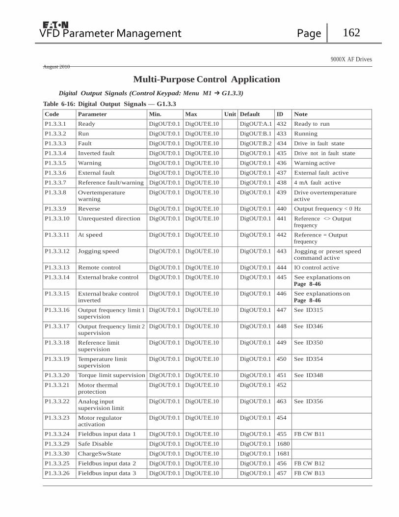
VFD Parameter Management Page 162
9000X AF Drives
August 2010
Multi-Purpose Control Application
Digital Output Signals (Control Keypad: Menu M1 ➔ G1.3.3)
Table 6-16: Digital Output Signals — G1.3.3
Code Parameter Min. Max Unit Default ID Note
P1.3.3.1 Ready DigOUT:0.1 DigOUT:E.10 DigOUT:A.1 432 Ready to run
P1.3.3.2 Run DigOUT:0.1 DigOUT:E.10 DigOUT:B.1 433 Running
P1.3.3.3 Fault DigOUT:0.1 DigOUT:E.10 DigOUT:B.2 434 Drive in fault state
P1.3.3.4 Inverted fault DigOUT:0.1 DigOUT:E.10 DigOUT:0.1 435 Drive not in fault state
P1.3.3.5 Warning DigOUT:0.1 DigOUT:E.10 DigOUT:0.1 436 Warning active
P1.3.3.6 External fault DigOUT:0.1 DigOUT:E.10 DigOUT:0.1 437 External fault active
P1.3.3.7 Reference fault/warning DigOUT:0.1 DigOUT:E.10 DigOUT:0.1 438 4 mA fault active
P1.3.3.8 Overtemperature warning
DigOUT:0.1 DigOUT:E.10 DigOUT:0.1 439 Drive overtemperature active
P1.3.3.9 Reverse DigOUT:0.1 DigOUT:E.10 DigOUT:0.1 440 Output frequency < 0 Hz
P1.3.3.10 Unrequested direction DigOUT:0.1 DigOUT:E.10 DigOUT:0.1 441 Reference <> Output frequency
P1.3.3.11 At speed DigOUT:0.1 DigOUT:E.10 DigOUT:0.1 442 Reference = Output frequency
P1.3.3.12 Jogging speed DigOUT:0.1 DigOUT:E.10 DigOUT:0.1 443 Jogging or preset speed command active
P1.3.3.13 Remote control DigOUT:0.1 DigOUT:E.10 DigOUT:0.1 444 IO control active
P1.3.3.14 External brake control DigOUT:0.1 DigOUT:E.10 DigOUT:0.1 445 See explanations on Page 8-46
P1.3.3.15 External brake control inverted
DigOUT:0.1 DigOUT:E.10 DigOUT:0.1 446 See explanations on
Page 8-46
P1.3.3.16 Output frequency limit 1 supervision
DigOUT:0.1 DigOUT:E.10 DigOUT:0.1 447 See ID315
P1.3.3.17 Output frequency limit 2 supervision
DigOUT:0.1 DigOUT:E.10 DigOUT:0.1 448 See ID346
P1.3.3.18 Reference limit supervision
DigOUT:0.1 DigOUT:E.10 DigOUT:0.1 449 See ID350
P1.3.3.19 Temperature limit supervision
DigOUT:0.1 DigOUT:E.10 DigOUT:0.1 450 See ID354
P1.3.3.20 Torque limit supervision DigOUT:0.1 DigOUT:E.10 DigOUT:0.1 451 See ID348
P1.3.3.21 Motor thermal protection
DigOUT:0.1 DigOUT:E.10 DigOUT:0.1 452
P1.3.3.22 Analog input supervision limit
DigOUT:0.1 DigOUT:E.10 DigOUT:0.1 463 See ID356
P1.3.3.23 Motor regulator activation
DigOUT:0.1 DigOUT:E.10 DigOUT:0.1 454
P1.3.3.24 Fieldbus input data 1 DigOUT:0.1 DigOUT:E.10 DigOUT:0.1 455 FB CW B11
P1.3.3.29 Safe Disable DigOUT:0.1 DigOUT:E.10 DigOUT:0.1 1680
P1.3.3.30 ChargeSwState DigOUT:0.1 DigOUT:E.10 DigOUT:0.1 1681
P1.3.3.25 Fieldbus input data 2 DigOUT:0.1 DigOUT:E.10 DigOUT:0.1 456 FB CW B12
P1.3.3.26 Fieldbus input data 3 DigOUT:0.1 DigOUT:E.10 DigOUT:0.1 457 FB CW B13

VFD Parameter Management Page 163
9000X AF Drives
August 2010
Multi-Purpose Control Application
Table 6-16: Digital Output Signals — G1.3.3 (Continued)
Code Parameter Min. Max Unit Default ID Note
P1.3.3.27 Fieldbus input data 4 DigOUT:0.1 DigOUT:E.10 DigOUT:0.1 169 FB CW B14
P1.3.3.28 Fieldbus input data 5 DigOUT:0.1 DigOUT:E.10 DigOUT:0.1 170 FB CW B15
CAUTION
Be ABSOLUTELY sure not to connect two functions to one and
same output in order to avoid function overruns and to ensure
flawless operation.
Limit Settings (Control Keypad: Menu M1 ➔ G1.3.4)
Table 6-17: Limit Settings — G1.3.4
Code Parameter Min. Max. Unit Default Cust ID Note
P1.3.4.1 Output frequency limit 1 supervision
0 3 0 315 0 = No limit 1 = Low limit supervision 2 = High limit supervision 3 = Brake-on control
P1.3.4.2 Output frequency limit 1; Supervised value
0.00 Par. 1.1.2 Hz 0.00 316
P1.3.4.3 Output frequency limit 2 supervision
0 4 0 346 0 = No limit 1 = Low limit supervision 2 = High limit supervision 3 = Brake-off control 4 = Brake on/off-control
P1.3.4.4 Output frequency limit 2; Supervised value
0.00 Par. 1.1.2 Hz 0.00 347
P1.3.4.5 Torque limit supervision
0 3 0 348 0 = Not used 1 = Low limit supervision 2 = High limit supervision 3 = Brake-off control
P1.3.4.6 Torque limit supervision value
-1000.0 1000.0 % 100.0 349
P1.3.4.7 Reference limit supervision
0 2 0 350 0 = Not used 1 = Low limit 2 = High limit
P1.3.4.8 Reference limit supervision value
0.00 Par. 1.1.2 % 0.00 351
P1.3.4.9 External brake-off delay
0.0 100.0 s 0.5 352
P1.3.4.10 External brake-on delay
0.0 100.0 s 1.5 353
P1.3.4.11 FC temperature supervision
0 2 0 354 0 = Not used 1 = Low limit 2 = High limit
P1.3.4.12 FC temperature supervised value
-10 75 ∞C 0 355
6-16 For more information visit: www.eaton.com MN04004001E

VFD Parameter Management Page 164
9000X AF Drives
August 2010
Multi-Purpose Control Application
Table 6-17: Limit Settings — G1.3.4 (Continued)
Code Parameter Min. Max. Unit Default Cust ID Note
P1.3.4.13 Ain Supv Input 0 4 0 356 0 = Not used 1 = AI1 2 = AI2 3 = AI3 4 = AI4
P1.3.4.14 Ain Supv Llim 0 Par. 1.3.4.15 % 10.00 357
P1.3.4.15 Ain Supv Hlim Par. 1.3.4.14 100.00 % 90.00 358
Analog Output 1 (Control Keypad: Menu M1 ➔ G1.3.5)
Table 6-18: Analog Output 1 Parameters — G1.3.5
Code Parameter Min. Max. Unit Default Cust ID Note
P1.3.5.1 Analog output 1 signal selection
AnOUT:0.1 AnOUT:E.10 A.1 464
P1.3.5.2 Analog output 1 function
0 15 1 307 0 = Not used
1 = Output freq. (0 – fmax) 2 = Freq. reference (0 – fmax) 3 = Motor speed (0 – Motor nominal speed) 4 = Motor current (0 – InMotor) 5 = Motor torque (0 – TnMotor) 6 = Motor power (0 – PnMotor) 7 = Motor voltage (0 – UnMotor) 8 = DC-Bus volt (0 – 1000V) 9 = AI1 10 = AI2 11 = Output freq. (fmin - fmax) 12 = Motor torque (–2…+2xTNmot)
13 = Motor power (–2…+2xTNmot)
14 = PT100 temperature 15 = FB Data In 4
P1.3.5.3 Analog output 1 filter time
0.00 10.00 s 1.00 308 0 = No filtering
P1.3.5.4 Analog output 1 inversion
0 1 0 309 0 = Not inverted
1 = Inverted
P1.3.5.5 Analog output 1 minimum
0 1 0 310 0 = 0 mA 1 = 4 mA
P1.3.5.6 Analog output 1 scale
10 1000 % 100 311
P1.3.5.7 Analog output 1 offset
-100.00 100.00 % 0.00 375
MN04004001E For more information visit: www.eaton.com 6-17

VFD Parameter Management Page 165
9000X AF Drives
August 2010
Multi-Purpose Control Application
Analog Output 2 (Control Keypad: Menu M1 ➔ G1.3.6)
Table 6-19: Analog Output 2 Parameters — G1.3.6
Code Parameter Min. Max. Unit Default Cust ID Note
P1.3.6.1 Analog output 2 signal selection
AnOUT:0.1 AnOUT:E.10 0.1 471
P1.3.6.2 Analog output 2 function
0 13 4 472 See par. 1.3.5.2
P1.3.6.3 Analog output 2 filter time
0.00 10.00 s 1.00 473 0 = No filtering
P1.3.6.4 Analog output 2 inversion
0 1 0 474 0 = Not inverted 1 = Inverted
P1.3.6.5 Analog output 2 minimum
0 1 0 475 0 = 0 mA 1 = 4 mA
P1.3.6.6 Analog output 2 scale
10 1000 % 100 476
P1.3.6.7 Analog output 2 offset
-100.00 100.00 % 0.00 477
Analog Output 3 (Control Keypad: Menu M1 ➔ G1.3.7)
Table 6-20: Analog Output 3 Parameters — G1.3.7
Code Parameter Min. Max. Unit Default Cust ID Note
P1.3.7.1 Analog output 3 signal selection
AnOUT:0.1 AnOUT:E.10 0.1 478
P1.3.7.2 Analog output 3 function
0 13 5 479 See par. 1.3.5.2
P1.3.7.3 Analog output 3 filter time
0.00 10.00 s 1.00 480 0 = No filtering
P1.3.7.4 Analog output 3 inversion
0 1 0 481 0 = Not inverted
1 = Inverted
P1.3.7.5 Analog output 3 minimum
0 1 0 482 0 = 0 mA 1 = 4 mA
P1.3.7.6 Analog output 3 scale
10 1000 % 100 483
P1.3.7.7 Analog output 3 offset
-100.00 100.00 % 0.00 484
6-18 For more information visit: www.eaton.com MN04004001E

VFD Parameter Management Page 166
9000X AF Drives
August 2010
Multi-Purpose Control Application
Drive Control Parameters (Control Keypad: Menu M1 ➔ G1.4)
Table 6-21: Drive Control Parameters — G1.4
Code Parameter Min. Max. Unit Default Cust ID Note
P1.4.1 Ramp 1 shape 0.0 10.0 s 0.00 500 0 = Linear >0 = S-curve ramp time
P1.4.2 Ramp 2 shape 0.0 10.0 s 0.0 501 0 = Linear >0 = S-curve ramp time
P1.4.3 Acceleration time
2 0.1 3000.0 s 10.0 502
P1.4.4 Deceleration time 2
0.1 3000.0 s 10.0 503
P1.4.5 Brake chopper 0 4 0 504 0 = Disabled 1 = Used when running 2 = External brake chopper 3 = Used when stopped/ running 4 = Used when running (no testing)
P1.4.6 Start function 0 1 0 505 0 = Ramp 1 = Flying start
P1.4.7 Stop function 0 3 1 506 0 = Coasting
1 = Ramp 2 = Ramp+Run enable coast 3 = Coast+Run enable ramp
P1.4.8 DC braking current 0.00 IL A 0.7 x IH 507
P1.4.9 DC braking time at stop
0.00 600.00 s 0.00 508 0 = DC brake is off at stop
P1.4.10 Frequency to start DC braking during ramp stop
0.10 10.00 Hz 1.50 515
P1.4.11 DC braking time at start
0.00 600.00 s 0.00 516 0 = DC brake is off at start
P1.4.12 Flux brake 0 1 0 520 0 = Off 1 = On
P1.4.13 Flux braking current
0.1 x IH 2 x IH A IH 519
P1.4.14 High Speed Mode 0 1 0/No 1522 0 = No
1 = Yes
MN04004001E For more information visit: www.eaton.com 6-19

VFD Parameter Management Page 167
9000X AF Drives
August 2010
Multi-Purpose Control Application
Skip Frequency Parameters (Control Keypad: Menu M1 ➔ G1.5)
Table 6-22: Skip Frequency Parameters — G1.5
Code Parameter Min. Max. Unit Default Cust ID Note
P1.5.1 Skip frequency range 1 low limit
0.00 Par. 1.5.2 Hz 0.00 509
P1.5.2 Skip frequency range 1 high limit
0.00 Par. 1.1.2 Hz 0.00 510 0 = Skip frequency range 1 not used
P1.5.3 Skip frequency range 2 low limit
0.00 Par. 1.5.4 Hz 0.00 511
P1.5.4 Skip frequency range 2 high limit
0.00 Par. 1.1.2 Hz 0.00 512 0 = Skip frequency range 2 not used
P1.5.5 Skip frequency range 3 low limit
0.00 Par. 1.5.6 Hz 0.00 513
P1.5.6 Skip frequency range 3 high limit
0.00 Par. 1.1.2 Hz 0.00 514 0 = Skip frequency range 3 not used
P1.5.7 Skip frequency acc./dec. ramp
0.1 10.0 Times 1.0 518
Motor Control Parameters (Control Keypad: Menu M1 ➔ G1.6)
Table 6-23: Motor Control Parameters — G1.6
Code Parameter Min. Max. Unit Default Cust ID Note
P1.6.1 Motor control mode 0 4 0 600 SVX: 0 = Freq Control 1 = OL SpeedCont 2 = OL Torq Ctrl SPX Only 3 = CL SpeedCont 4 = CL Torq Ctrl
P1.6.2 V/Hz Boost 0 1 0 109 0 = Not used
1 = Automatic torque boost
P1.6.3 V/Hz Ratio Select 0 3 0 108 0 = Linear 1 = Squared 2 = Programmable 3 = Linear with flux optim.
P1.6.4 Field weakening point 8.00 650 Hz 60.00 602
P1.6.5 Voltage at field weakening point
10.00 200.00 % 100.00 603 n% x Unmot
P1.6.6 V/Hz curve midpoint frequency
0.00 650 Hz 60.00 604
P1.6.7 V/Hz curve midpoint voltage
0.00 100.00 % 100.00 605 n% x Unmot
Parameter max. value = par. 1.6.5
P1.6.8 Output voltage at zero frequency
0.00 40.00 % 1.30 606 n% x Unmot
6-20 For more information visit: www.eaton.com MN04004001E

VFD Parameter Management Page 168
9000X AF Drives
August 2010
Multi-Purpose Control Application
Table 6-23: Motor Control Parameters — G1.6 (Continued)
Code Parameter Min. Max. Unit Default Cust ID Note
P1.6.9 Switching frequency
1.0 16 kHz 10 601 See Table 8-12 on Page 8-57
for exact values
P1.6.10 Overvoltage controller
0 2 1 607 0 = Not used
1 = Used (no ramping) 2 = Used (ramping)
P1.6.11 Undervoltage controller
0 1 1 608 0 = Off
1 = On:NoRamping 2 = On:Ramping
P1.6.12 Motor control mode 2
0 2/6 2 521 See par. 1.6.1
P1.6.13 Speed controller
P gain (open loop) 0 32767 3000 637
P1.6.14 Speed controller
I gain (open loop) 0 32767 300 638
P1.6.15 Load Drooping 0.00 100.00 0.00 620 Drooping % of nominal speed at nominal torque
P1.6.16 Identification 0 2 0 631 0 = No Action
1 = ID No Run SPX Only 2 = ID With Run
Closed Loop parameter group 1.6.17 (SPX only)
P1.6.17.1 MagnCurrent 0 90 A 0 612
P1.6.17.2 Speed Control Kp 1 1000 30 613
P1.6.17.3 Speed Control Ti -3200 3200 ms 100 614
P1.6.17.4 Reserved -32000 32000 x 0 1499
P1.6.17.5 Accel.Compens. 0 300 s 0 626
P1.6.17.6 Slip Adjust 0 500 % 75 619
P1.6.17.7 Start Magn Curr 0 61 A 0 627
P1.6.17.8 Start Magn Time 0 32000 ms 0 628
P1.6.17.9 Start 0SpeedTime 0 32000 ms 100 615
P1.6.17.10 Stop 0 SpeedTime 0 32000 ms 100 616
P1.6.17.11 StartUp Torque 0 3 0/Not
Used 621 0 = Not Used
1 = TorqueMemory 2 = Torque Ref 3 = Torq Fwd/Rev
P1.6.17.12 Startup Torq FWD -300 300 % 0 633
P1.6.17.13 Startup Torq REV -300 300 % 0 634
P1.6.17.14 Reserved -32000 32000 x 0 1499
P1.6.17.15 Encoder1FiltTime 0 100 ms 0 618
P1.6.17.16 Reserved -32000 32000 x 0 1499
P1.6.17.17 CurrentControlKp 0 100 % 40 617
P.1.6.17.18 Reserved -32000 32000 x 0 1499

VFD Parameter Management Page 169
9000X AF Drives
August 2010
Multi-Purpose Control Application
Protections (Control Keypad: Menu M1 ➔ G1.7)
Table 6-24: Protections — G1.7
Code Parameter Min. Max. Unit Default Cust ID Note
P1.7.1 Ref Fault Resp 0 5 0 700 0 = No Action 1 = Warning 2 = Warn:Stop 3 = Warn:PrevFre 4 = Warn:PresetF 5 = Fault 6 = Fault,Coast
P1.7.2 Ref Fault Freq. 0.00 Par. 1.1.2 Hz 0.00 728
P1.7.3 Response to external fault
0 3 2 701 0 = No response 1 = Warning 2 = Fault.stop acc. to 1.4.7 3 = Fault.stop by coasting P1.7.4 Input phase
supervision 0 3 3 730
P1.7.5 Response to undervoltage fault
1 3 0 727
P1.7.6 Output phase supervision
0 3 2 702
P1.7.7 Earth fault protection
0 3 2 703
P1.7.8 Thermal protection of the motor
0 3 2 704
P1.7.9 Motor ambient temperature factor
-100.0 100.0 % 0.0 705
P1.7.10 Motor cooling factor at zero speed
0.0 150.0 % 40.0 706
P1.7.11 Motor thermal time constant
1 200 min 40 707
P1.7.12 Motor duty cycle 0 100 % 100 708
P1.7.13 Stall protection 0 3 0 709 0 = No response 1 = Warning 2 = Fault.stop acc. to 1.4.7 3 = Fault.stop by coasting
P1.7.14 Stall current 0.00 InMotor x 2 A IL 710
P1.7.15 Stall time limit 1.00 120.00 s 15.00 711
6-22 For more information visit: www.eaton.com MN04004001E

VFD Parameter Management Page 170
9000X AF Drives
August 2010
Multi-Purpose Control Application
Table 6-24: Protections — G1.7 (Continued)
Code Parameter Min. Max. Unit Default Cust ID Note
P1.7.16 Stall frequency limit 1.0 Par. 1.1.2 Hz 25.0 712
P1.7.17 Underload protection
0 3 0 713 0 = No response
1 = Warning 2 = Fault.stop acc. to 1.4.7 3 = Fault.stop by coasting
P1.7.18 Field weakening area load
10.0 150.0 % 50.0 714
P1.7.19 Zero frequency load 5.0 150.0 % 10.0 715
P1.7.20 Underload protection time limit
2.00 600.00 s 20.00 716
P1.7.21 Response to thermistor fault
0 3 2 732 0 = No response 1 = Warning 2 = Fault.stop acc. to 1.4.7 3 = Fault.stop by coasting
P1.7.22 Response to fieldbus fault
0 3 2 733 See P1.7.21
P1.7.23 Response to slot fault
0 3 2 734 See P1.7.21
P1.7.24 No. of PT100 inputs 0 3 0 739
P1.7.25 Response to PT100 fault
0 3 0 740 0 = No response 1 = Warning 2 = Fault.stop acc. to 1.4.7 3 = Fault.stop by coasting
P1.7.26 PT100 warning limit -30.0 200.0 Cº 120.0 741
P1.7.27 PT100 fault limit -30.0 200.0 Cº 130.0 742
P1.7.28 PT100 Numbers 2 0 3 0 743
P1.7.29 PT100 Flt Resp 2 0 3 0/No Action
744 See External Fault
P1.7.30 PT100WarnLimit2 -30 200 °C 120 745
P1.7.31 PT100 FltLimit 2 -30 200 °C 130 746
P1.7.32 FB WatchdogDelay 0 10.00 s 0 1354 0 = Not monitored
P1.7.33 FCW monitor bit 0 1 1 / Fault
High 771
P1.7.34 FB monitor delay 0 10.00 s 0 772 0 = Not monitored
P1.7.35 Ref fault select 0 4 1 / AI2 770 0 = AI1
1 = AI2 2 = AI3 3 = AI4 4 = Fieldbus
SPX Only
P1.7.36 SafeDisable Mode 1 2 1/ Warning
755 1 = Warning 2 = Fault
MN04004001E For more information visit: www.eaton.com 6-23

VFD Parameter Management Page 171
9000X AF Drives
August 2010
Multi-Purpose Control Application
Autorestart Parameters (Control Keypad: Menu M1 ➔ G1.8)
Table 6-25: Autorestart Parameters — G1.8
Code Parameter Min. Max. Unit Default Cust ID Note
P1.8.1 Wait time 0.10 10.00 s 0.50 717 P1.8.2 Trial time 0.00 60.00 s 30.00 718 P1.8.3 Start mode 0 2 0 719 0 = Ramp
1 = Flying start 2 = According to par. 1.4.6
P1.8.4 Number of tries after undervoltage trip
0 10 0 720
P1.8.5 Number of tries after overvoltage trip
0 10 0 721
P1.8.6 Number of tries after overcurrent trip
0 3 0 722
P1.8.7 Number of tries after reference trip
0 10 0 723
P1.8.8 Number of tries after motor temperature fault trip
0 10 0 726
P1.8.9 Number of tries after external fault trip
0 10 0 725
P1.8.10 Number of tries after underload fault trip
0 10 1 738
Fieldbus Parameters (Control Keypad: Menu M1 ➔ G1.9)
Table 6-26: Fieldbus Parameters — G1.9
Code Parameter Min. Max. Unit Default Cust ID Note
P1.9.1 Fieldbus min scale 0.00 320.00 Hz 0.00 850
P1.9.2 Fieldbus max scale
0.00 320.00 Hz 0.00 851
P1.9.3 Fieldbus data out 1 selection
0 10000 1 852 Choose monitoring data with parameter ID
P1.9.4 Fieldbus data out 2 selection
0 10000 2 853 Choose monitoring data with parameter ID
P1.9.5 Fieldbus data out 3 selection
0 10000 3 854 Choose monitoring data with parameter ID
P1.9.6 Fieldbus data out 4 selection
0 10000 4 855 Choose monitoring data with parameter ID
P1.9.7 Fieldbus data out 5 selection
0 10000 5 856 Choose monitoring data with parameter ID
P1.9.8 Fieldbus data out 6 selection
0 10000 6 857 Choose monitoring data with parameter ID

VFD Parameter Management Page 172
9000X AF Drives
August 2010
Multi-Purpose Control Application
Table 6-26: Fieldbus Parameters — G1.9 (Continued)
Code Parameter Min. Max. Unit Default Cust ID Note
P1.9.9 Fieldbus data out 7 selection
0 10000 7 858 Choose monitoring data with parameter ID
P1.9.10 Fieldbus data out 8 selection
0 10000 37 859 Choose monitoring data with parameter ID
P1.9.11 FB Data In1 Sel 0 2000 0 876 Writes to drive ID only on a change
P1.9.12 FB Data In2 Sel 0 2000 0 877 Writes to drive ID only on a change
Torque Control Parameters (Control Keypad: Menu M1 ➔ G1.10)
Table 6-27: Torque Control Parameters — G1.10
Code Parameter Min. Max. Unit Default Cust ID Note
P1.10.1 Torque limit 0.0 400.0 % 300.0 609
P1.10.2 Torque limit control P-gain
0.0 32000 3000 610
P1.10.3 Torque limit control I-gain
0.0 32000 200 611
P1.10.4 Torque reference selection
0 8 0 641 0 = Not used
1 = AI1 2 = AI2 3 = AI3 4 = AI4 5 = AI1 joystick 6 = AI2 joystick 7 = Torque reference from keypad, R2.4 8 = Fieldbus
P1.10.5 Torque reference max.
-300.0 300.0 % 100 642
P1.10.6 Torque reference min.
-300.0 300.0 % 0.0 643
P1.10.7 Torque speed limit 0 2 1 644 0 = Max frequency
1 = Selected freq. reference 2 = Preset speed 7
P1.10.8 Minimum frequency for open loop torque control
0.00 par.1.1.1 Hz 3.00 636
P1.10.9 Torque controller P gain
0 32000 150 639
P1.10.10 Torque controller
I gain 0 32000 10 640
MN04004001E For more information visit: www.eaton.com 6-25

VFD Parameter Management Page 173
9000X AF Drives
August 2010
Multi-Purpose Control Application
Keypad Control (Control Keypad: Menu M2)
The parameters for the selection of control place and direction on the keypad are listed
below. See the Keypad control menu in the 9000X AF Drives User Manual.
Table 6-28: Keypad Control Parameters — M2
Code Parameter Min. Max. Unit Default Cust ID Note
P2.1 Control place 0 2 0 Keypad L/R
1685 0 = Keypad L/R 1 = Local 2 = Remote 3 = I/O Select
R2.2 Keypad reference Par. 1.1.1
Par. 1.1.2 Hz
P2.3 Direction (on keypad)
0 1 0 123 0 = Forward
1 = Reverse
P2.4 Stop button 0 1 1 114 0 = Limited function of Stop button 1 = Stop button always enabled
R2.5 Torque reference 0.0 100.0 % 0.0
P2.6 Hide Operate M 0 1 0/No 1707 0 = No 1 = Yes
System Menu (Control Keypad: Menu M5)
For parameters and functions related to the general use of the drive, such as application
and language selection, customized parameter sets or information about the hardware and
software, see Chapter 5 in the 9000X AF Drives User Manual.
Expander Boards (Control Keypad: Menu M6)
The M6 menu shows the expander and option boards attached to the control board and
board-related information. For more information, see Chapter 5 in the 9000X AF Drives
User Manual.
6-26 For more information visit: www.eaton.com MN04004001E
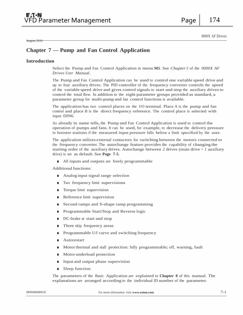
VFD Parameter Management Page 174
9000X AF Drives
August 2010
Chapter 7 — Pump and Fan Control Application Introduction
Select the Pump and Fan Control Application in menu M5. See Chapter 5 of the 9000X AF
Drives User Manual.
The Pump and Fan Control Application can be used to control one variable speed drive and
up to four auxiliary drives. The PID controller of the frequency converter controls the speed
of the variable speed drive and gives control signals to start and stop the auxiliary drives to
control the total flow. In addition to the eight parameter groups provided as standard, a
parameter group for multi-pump and fan control functions is available.
The application has two control places on the I/O terminal. Place A is the pump and fan
control and place B is the direct frequency reference. The control place is selected with
input DIN6.
As already its name tells, the Pump and Fan Control Application is used to control the
operation of pumps and fans. It can be used, for example, to decrease the delivery pressure
in booster stations if the measured input pressure falls below a limit specified by the user.
The application utilizes external contactors for switching between the motors connected to
the frequency converter. The autochange feature provides the capability of changing the
starting order of the auxiliary drives. Autochange between 2 drives (main drive + 1 auxiliary
drive) is set as default. See Page 7-5.
● All inputs and outputs are freely programmable
Additional functions:
● Analog input signal range selection
● Two frequency limit supervisions
● Torque limit supervision
● Reference limit supervision
● Second ramps and S-shape ramp programming
● Programmable Start/Stop and Reverse logic
● DC-brake at start and stop
● Three skip frequency areas
● Programmable U/f curve and switching frequency
● Autorestart
● Motor thermal and stall protection: fully programmable; off, warning, fault
● Motor underload protection
● Input and output phase supervision
● Sleep function
The parameters of the Basic Application are explained in Chapter 8 of this manual. The
explanations are arranged according to the individual ID number of the parameter.
MN04004001E For more information visit: www.eaton.com 7-1

VFD Parameter Management Page 175
CMB connected to GND CMA connected to GND
9000X AF Drives
August 2010
Control I/O
Reference potentiometer 1 – 10 kW
Pump and Fan Control Application Table 7-1: Pump and Fan Control Application Default I/O Configuration and Connection Example (with 2-wire transmitter)
Terminal Signal Description
OPTA1
1 +10Vref Reference output Voltage for potentiometer, etc.
2-wire
2 AI1+ Analog input, voltage range
0 – 10V DC
Voltage input frequency reference
transmitter 3 AI1- I/O Ground Ground for reference and controls
+ Actual value 4 AI2+ Analog input, current range Current input frequency reference - + 5 AI2- 0 – 20mA
- (0)4 … 20 mA 6 +24V Control voltage output Voltage for switches, etc. max 0.1A
7 GND I/O ground Ground for reference and controls
8 DIN1 Start/Stop; Control place A (PID controller) (programm.)
9 DIN2 Interlock 1 (programmable)
10 DIN3 Interlock 2 (programmable)
Contact closed = start
Contact closed = Interlock used Contact open = Interlock not used
Contact closed = Interlock used Contact open = Interlock not used
11 CMA Common for DIN1 – DIN3 Connect to GND or +24V
12 +24V Control voltage output Voltage for switches (see #6)
13 GND I/O ground Ground for reference and controls
14 DIN4 Start/Stop Control place B (Direct frequency reference) (programmable)
15 DIN5 Jogging speed selection
(programmable)
16 DIN6 Control place A/B selection (programmable)
Contact closed = Start
Contact closed = Jogging speed active
Contact open = Control place A is active Contact closed = Control place B is active
17 CMB Common for DIN4 – DIN6 Connect to GND or +24V
18 AO1+ Output frequency Programmable; See Tables 7-12, 7-13
FAULT
19 AO1- (GND)
Analog output and 7-14 Range 0 – 20 mA/RL, max. 500W
20 DO1 Digital output FAULT
Programmable Open collector, I ≤ 50 mA, V ≤ 48V DC
OPTA2
21 RO1 Relay output 1 Programmable, see Table 7-10
22 RO1
23 RO1
RUN
24 RO2 Relay output 2 Programmable, see Table 7-10
220V
AC
25 RO2
26 RO2
FAULT
Note: For more information on jumper selections, see the 9000X AF Drives User
Manual, Chapter 4. Jumper Block X3: CMA and CMB Grounding
CMB isolated from GND CMA isolated from GND
CMB and CMA internally connected together, isolated from GND
= Factory default

VFD Parameter Management Page 176
9000X AF Drives
August 2010
Pump and Fan Control Application
230V AC
22
RO1
24V DC
SPX9000 OPTA2
25
RO2 12 9 DIN2 DIN3 10
23 26
Autom. 0 Line
S1
Autom. 0 Line
S2
K2 K1
K2 K2
K1.1 K1 K2.1 K2
K1 K1.1 K2 K2.1
M1/SPX9000 M1/Line M2/SPX9000 M2/Line
Figure 7-1: 2-Pump Autochange System Principal Control Diagram
MN04004001E For more information visit: www.eaton.com 7-3

VFD Parameter Management Page 177
9000X AF Drives
August 2010
Pump and Fan Control Application
230V AC
SPX9000 OPTA1
24V DC
12 9 DIN2
SPX9000 OPTA1
DIN3
10
SPX9000 OPTA1
DIN4
14
22
SPX9000 25
OPTB5
23 26
SPX9000 28
OPTB5
29
A O Line A O Line A O Line
S1 S2 S3
K3 K2 K3
K2
K3 K1 K3
K1
K1 K2 K1
K2
K1.1 K1
K1 K1.1
K2.1 K2
K2 K2.1
K3.1 K3
K3 K3.1
M1/SPX9000 M1/Line M2/SPX9000 M2/Line M1/SPX9000 M3/Line
Figure 7-2: 3-Pump Autochange System Principal Control Diagram
7-4 For more information visit: www.eaton.com MN04004001E

VFD Parameter Management Page 178
9000X AF Drives
August 2010
Pump and Fan Control Application
Short Description of Function and Essential Parameters
Automatic Changing Between Drives (Autochange, P1.9.24)
The Autochange function allows the starting and stopping order of drives controlled by
the pump and fan automatics to be changed at desired intervals. The drive controlled by
frequency converter can also be included in the automatic changing and locking sequence
(par. 1.9.25). The Autochange function makes it possible to equalize the run times of the
motors and to prevent e.g. pump stalls due to too long running breaks.
● Apply the Autochange function with parameter 1.9.24, Autochange.
● The autochange takes place when the time set with parameter 1.9.26, Autochange
interval, has expired and the capacity used is below the level defined with parameter
1.9.28, Autochange frequency limit.
● The running drives are stopped and re-started according to the new order.
● External contactors controlled through the relay outputs of the frequency converter
connect the drives to the frequency converter or to the mains. If the motor controlled
by the frequency converter is included in the autochange sequence, it is always
controlled through the relay output activated first. The other relays activated later
control the auxiliary drives (see Figure 7-4 and Figure 7-5).
Parameter 1.9.24 — Autochange
0 Autochange not used
1 Autochange used
The automatic change of starting and stopping order is activated and applied to either the
auxiliary drives only or the auxiliary drives and the drive controlled by the frequency
converter, depending on the setting of parameter 1.9.25, Automatics selection. By default,
the Autochange is activated for 2 drives. See Figure 7-1 and Figure 7-4.
Parameter 1.9.25 — Autochange/Interlockings Automatics Selection
0 Automatics (autochange/interlockings) applied to auxiliary drives only
The drive controlled by the frequency converter remains the same. Therefore, mains
contactor is needed for one auxiliary drive only.
1 All drives included in the autochange/interlockings sequence
The drive controlled by the frequency converter is included in the automatics and a contactor
is needed for each drive to connect it to either the mains or the frequency converter.
Parameter 1.9.26 — Autochange interval
After the expiry of the time defined with this parameter, the autochange function takes place
if the capacity used lies below the level defined with parameters 1.9.28 (Autochange frequency
limit) and 1.9.27 (Maximum number of auxiliary drives). Should the capacity exceed the
value of P1.9.28, the autochange will not take place before the capacity goes below this limit.
● The time count is activated only if the Start/Stop request is active at control place A.
● The time count is reset after the autochange has taken place or on removal of Start
request at control place A.
MN04004001E For more information visit: www.eaton.com 7-5

VFD Parameter Management Page 179
9000X AF Drives
August 2010
Pump and Fan Control Application
Parameters 1.9.27 — Maximum Number of Auxiliary Drives and
1.9.28 — Autochange Frequency Limit
These parameters define the level below which the capacity used must remain so that the
autochange can take place.
This level is defined as follows:
● If the number of running auxiliary drives is smaller than the value of parameter 1.9.27
the autochange function can take place.
● If the number of running auxiliary drives is equal to the value of parameter 1.9.27 and
the frequency of the controlled drive is below the value of parameter 1.9.28 the
autochange can take place.
● If the value of parameter 1.9.28 is 0.0 Hz, the autochange can take place only in rest
position (Stop and Sleep) regardless of the value of parameter 1.9.27.
Interlock Selection (P1.9.23)
This parameter is used to activate the interlock inputs. The interlocking signals come from
the motor switches. The signals (functions) are connected to digital inputs which are
programmed as interlock inputs using the corresponding parameters. The pump and fan
control automatics only control the motors with active interlock data.
● The interlock data can be used even when the Autochange function is not activated.
● If the interlock of an auxiliary drive is inactivated and another unused auxiliary drive
available, the latter will be put to use without stopping the frequency converter.
● If the interlock of the controlled drive is inactivated. all motors will be stopped and
re-started with the new setup.
● If the interlock is re-activated in Run status, the automatics functions according to
parameter 1.9.23, Interlock selection:
0 Not used
1 Update in stop
Interlocks are used. The new drive will be placed last in the autochange line without stopping
the system. However, if the autochange order now becomes, for example, [P1 ➔ P3 ➔ P4 ➔ P2], it will be updated in the next Stop (autochange, sleep, stop, etc.).
Example:
[P1 ➔ P3 ➔ P4] ➔ [P2 LOCKED] ➔ [P1 ➔ P3 ➔ P4 ➔ P2] ➔ [SLEEP] ➔ [P1 ➔ P2 ➔ P3 ➔ P4]
2 Stop & Update
Interlockings are used. The automatics will stop all motors immediately and re-start with a
new setup.
Example:
[P1 ➔ P2 ➔ P4] ➔ [P3 LOCKED] ➔ [STOP] ➔ [P1 ➔ P2 ➔ P3 ➔ P4]
See Page 7-7 Examples.
7-6 For more information visit: www.eaton.com MN04004001E

VFD Parameter Management Page 180
9000X AF Drives
August 2010
Pump and Fan Control Application
Examples
Pump and fan automatics with interlocks and no autochange
Situation: One controlled drive and three auxiliary drives.
Parameter settings: 1.9.1 = 3, 1.9.25 = 0
Interlock feedback signals used, autochange not used.
Parameter settings: 1.9.23 = 1, 1.9.24 = 0
The interlock feedback signals come from the digital inputs selected with
parameters 1.2.6.18 to 1.2.6.21.
The Auxiliary drive 1 control (par. 1.3.1.27) is enabled through Interlock 1
(par. 1.2.6.18), the Auxiliary drive 2 control (par. 1.3.1.28) through Interlock
2 (par. 1.2.6.19) etc.
Phases: 1) The system and the motor controlled by the frequency converter are
started.
2) The Auxiliary drive 1 starts when the main drive reaches the starting
frequency set (par. 1.9.2).
3) The main drive decreases speed down to Auxiliary drive 1 Stop frequency
(par. 1.9.3) and starts to rise toward the Start frequency of Auxiliary drive 2,
if needed.
4) The Auxiliary drive 2 starts when the main drive has reached the starting
frequency set (par. 1.9.4).
5) The Interlock feedback is removed from Aux. drive 2. Because the Aux.
drive 3 is unused, it will be started to replace the removed Aux. drive 2.
6) The main drive increases speed to maximum because no more auxiliary
drives are available.
7) The removed Aux. drive 2 is reconnected and placed last in the auxiliary
drive start order which now is 1-3-2. The main drive decreases speed to the
set Stop frequency. The auxiliary drive start order will be updated either
immediately or in the next Stop (autochange, sleep, stop, etc.) according to
par. 1.9.23.
8) If still more power is needed, the main drive speed rises up to the
maximum frequency placing 100% of the output power in the system’s
disposal.
When the need of power decreases, the auxiliary drives turn off in the opposite order
(2-3-1; after the update 3-2-1).
MN04004001E For more information visit: www.eaton.com 7-7
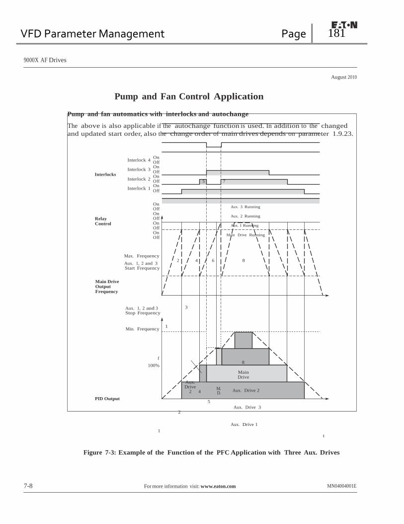
VFD Parameter Management Page 181
Off
9000X AF Drives
August 2010
Pump and Fan Control Application
Pump and fan automatics with interlocks and autochange
The above is also applicable if the autochange function is used. In addition to the changed
and updated start order, also the change order of main drives depends on parameter 1.9.23.
Interlocks
Relay Control
Interlock 4 On Off
Interlock 3 On
Interlock 2 On Off
Interlock 1 On Off
On Off On Off On Off On Off
5 7
Aux. 3 Running
Aux. 2 Running
Aux. 1 Running
Main Drive Running
Max. Frequency
Aux. 1, 2 and 3 Start Frequency
2 4 6 8
Main Drive Output Frequency
Aux. 1, 2 and 3 3 Stop Frequency
Min. Frequency 1
PID Output
f
100%
1
Aux. Drive M.
2 4 D.
5 2
8
Main Drive
Aux. Drive 2
Aux. Drive 3
Aux. Drive 1
t
Figure 7-3: Example of the Function of the PFC Application with Three Aux. Drives
7-8 For more information visit: www.eaton.com MN04004001E

VFD Parameter Management Page 182
9000X AF Drives
August 2010
Pump and Fan Control Application
PE L1
L2
L3
F3 F1 F2 Q1
SVX9000
L1 L2 L3
U V W
K1.1 K2.1
K1 K2
PE
U V W
M M1
3
PE
U V W
M M2
3
Figure 7-4: Example of 2-Pump Autochange, Main Diagram
PE L1 L2 L3
Q1 F3
F1 F2 F2
L1 L2 L3
SVX9000 K1.1 K2.1 K3.1
U V W
K1 K2 K3
PE
U V W
M1 M
3
U V W
M2 M 3
PE PE
U V W
M2 M
3
Figure 7-5: Example of 3-Pump Autochange, Main Diagram
MN04004001E For more information visit: www.eaton.com 7-9
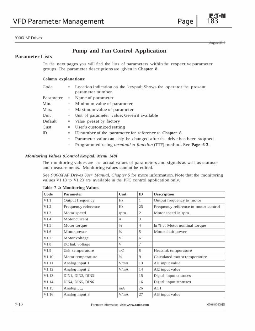
VFD Parameter Management Page 183
9000X AF Drives
August 2010
Parameter Lists Pump and Fan Control Application
On the next pages you will find the lists of parameters within the respective parameter
groups. The parameter descriptions are given in Chapter 8.
Column explanations:
Code = Location indication on the keypad; Shows the operator the present
parameter number
Parameter = Name of parameter
Min. = Minimum value of parameter
Max. = Maximum value of parameter
Unit = Unit of parameter value; Given if available
Default = Value preset by factory
Cust = User’s customized setting
ID = ID number of the parameter for reference to Chapter 8
= Parameter value can only be changed after the drive has been stopped = Programmed using terminal to function (TTF) method. See Page 6-3.
Monitoring Values (Control Keypad: Menu M8)
The monitoring values are the actual values of parameters and signals as well as statuses
and measurements. Monitoring values cannot be edited.
See 9000X AF Drives User Manual, Chapter 5 for more information. Note that the monitoring
values V1.18 to V1.23 are available in the PFC control application only.
Table 7-2: Monitoring Values
Code Parameter Unit ID Description
V1.1 Output frequency Hz 1 Output frequency to motor
V1.2 Frequency reference Hz 25 Frequency reference to motor control
V1.3 Motor speed rpm 2 Motor speed in rpm
V1.4 Motor current A 3
V1.5 Motor torque % 4 In % of Motor nominal torque
V1.6 Motor power % 5 Motor shaft power
V1.7 Motor voltage V 6
V1.8 DC link voltage V 7
V1.9 Unit temperature ∞C 8 Heatsink temperature
V1.10 Motor temperature % 9 Calculated motor temperature
V1.11 Analog input 1 V/mA 13 AI1 input value
V1.12 Analog input 2 V/mA 14 AI2 input value
V1.13 DIN1, DIN2, DIN3 15 Digital input statuses
V1.14 DIN4, DIN5, DIN6 16 Digital input statuses
V1.15 Analog Iout mA 26 AO1
V1.16 Analog input 3 V/mA 27 AI3 input value
7-10 For more information visit: www.eaton.com MN04004001E
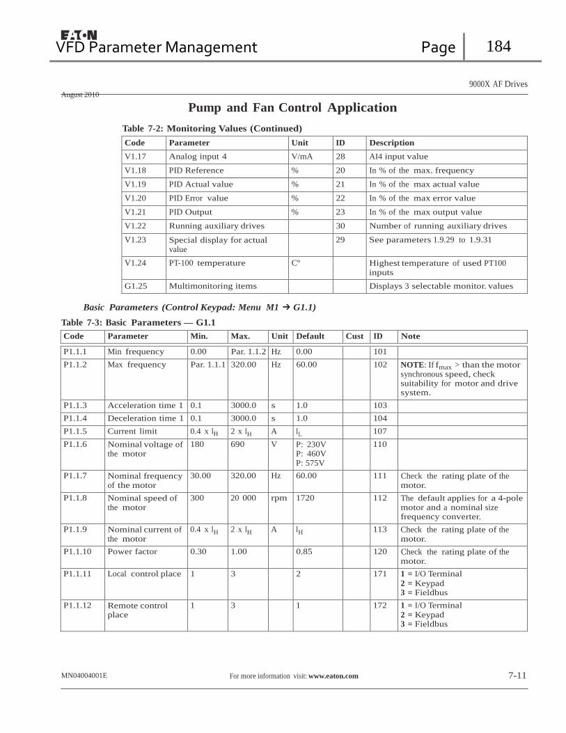
VFD Parameter Management Page 184
9000X AF Drives
August 2010
Pump and Fan Control Application
Table 7-2: Monitoring Values (Continued)
Code Parameter Unit ID Description
V1.17 Analog input 4 V/mA 28 AI4 input value
V1.18 PID Reference % 20 In % of the max. frequency
V1.19 PID Actual value % 21 In % of the max actual value
V1.20 PID Error value % 22 In % of the max error value
V1.21 PID Output % 23 In % of the max output value
V1.22 Running auxiliary drives 30 Number of running auxiliary drives
V1.23 Special display for actual value
29 See parameters 1.9.29 to 1.9.31
V1.24 PT-100 temperature Cº Highest temperature of used PT100 inputs
G1.25 Multimonitoring items Displays 3 selectable monitor. values
Basic Parameters (Control Keypad: Menu M1 ➔ G1.1)
Table 7-3: Basic Parameters — G1.1
Code Parameter Min. Max. Unit Default Cust ID Note
P1.1.1 Min frequency 0.00 Par. 1.1.2 Hz 0.00 101 P1.1.2 Max frequency Par. 1.1.1 320.00 Hz 60.00 102 NOTE: If fmax > than the motor
synchronous speed, check suitability for motor and drive system.
P1.1.3 Acceleration time 1 0.1 3000.0 s 1.0 103 P1.1.4 Deceleration time 1 0.1 3000.0 s 1.0 104 P1.1.5 Current limit 0.4 x IH 2 x IH A IL 107 P1.1.6 Nominal voltage of
the motor 180 690 V P: 230V
P: 460V P: 575V
110
P1.1.7 Nominal frequency of the motor
30.00 320.00 Hz 60.00 111 Check the rating plate of the motor.
P1.1.8 Nominal speed of the motor
300 20 000 rpm 1720 112 The default applies for a 4-pole motor and a nominal size frequency converter.
P1.1.9 Nominal current of the motor
0.4 x IH 2 x IH A IH 113 Check the rating plate of the motor.
P1.1.10 Power factor 0.30 1.00 0.85 120 Check the rating plate of the motor.
P1.1.11 Local control place 1 3 2 171 1 = I/O Terminal
2 = Keypad 3 = Fieldbus
P1.1.12 Remote control place
1 3 1 172 1 = I/O Terminal 2 = Keypad 3 = Fieldbus
MN04004001E For more information visit: www.eaton.com 7-11
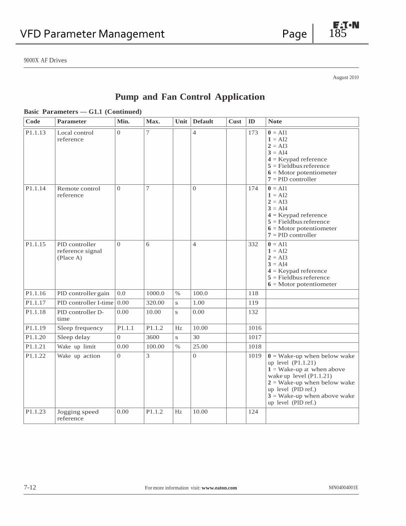
VFD Parameter Management Page 185
9000X AF Drives
August 2010
Pump and Fan Control Application
Basic Parameters — G1.1 (Continued)
Code Parameter Min. Max. Unit Default Cust ID Note
P1.1.13 Local control reference
0 7 4 173 0 = AI1 1 = AI2 2 = AI3 3 = AI4 4 = Keypad reference 5 = Fieldbus reference 6 = Motor potentiometer 7 = PID controller
P1.1.14 Remote control reference
0 7 0 174 0 = AI1 1 = AI2 2 = AI3 3 = AI4 4 = Keypad reference 5 = Fieldbus reference 6 = Motor potentiometer 7 = PID controller
P1.1.15 PID controller reference signal (Place A)
0 6 4 332 0 = AI1 1 = AI2 2 = AI3 3 = AI4 4 = Keypad reference 5 = Fieldbus reference 6 = Motor potentiometer
P1.1.16 PID controller gain 0.0 1000.0 % 100.0 118 P1.1.17 PID controller I-time 0.00 320.00 s 1.00 119 P1.1.18 PID controller D-
time 0.00 10.00 s 0.00 132
P1.1.19 Sleep frequency P1.1.1 P1.1.2 Hz 10.00 1016 P1.1.20 Sleep delay 0 3600 s 30 1017 P1.1.21 Wake up limit 0.00 100.00 % 25.00 1018 P1.1.22 Wake up action 0 3 0 1019 0 = Wake-up when below wake
up level (P1.1.21) 1 = Wake-up at when above wake up level (P1.1.21) 2 = Wake-up when below wake up level (PID ref.) 3 = Wake-up when above wake up level (PID ref.)
P1.1.23 Jogging speed reference
0.00 P1.1.2 Hz 10.00 124
7-12 For more information visit: www.eaton.com MN04004001E
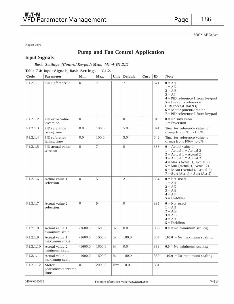
VFD Parameter Management Page 186
9000X AF Drives
August 2010
Input Signals Pump and Fan Control Application
Basic Settings (Control Keypad: Menu M1 ➔ G1.2.1)
Table 7-4: Input Signals, Basic Settings — G1.2.1
Code Parameter Min. Max. Unit Default Cust ID Note
P1.2.1.1 PID Reference 2 0 7 7 371 0 = AI1 1 = AI2 2 = AI3 3 = AI4 4 = PID reference 1 from keypad 5 = Fieldbus reference (FBProcessDataIN3) 6 = Motor potentiometer 7 = PID reference 2 from keypad
P1.2.1.2 PID error value inversion
0 1 0 340 0 = No inversion 1 = Inversion
P1.2.1.3 PID reference rising time
0.0 100.0 5.0 341 Time for reference value to change from 0% to 100%
P1.2.1.4 PID reference falling time
0.0 100.0 5.0 342 Time for reference value to change from 100% to 0%
P1.2.1.5 PID actual value selection
0 7 0 333 0 = Actual value 1 1 = Actual 1 + Actual 2 2 = Actual 1 – Actual 2 3 = Actual 1 * Actual 2 4 = Max (Actual 1, Actual 2) 5 = Min (Actual 1, Actual 2) 6 = Mean (Actual 1, Actual 2) 7 = Sqrt (Act 1) + Sqrt (Act 2)
P1.2.1.6 Actual value 1 selection
0 5 2 334 0 = Not used 1 = AI1 2 = AI2 3 = AI3 4 = AI4 5 = Fieldbus
P1.2.1.7 Actual value 2 selection
0 5 0 335 0 = Not used 1 = AI1 2 = AI2 3 = AI3 4 = AI4 5 = Fieldbus
P1.2.1.8 Actual value 1 minimum scale
-1600.0 1600.0 % 0.0 336 0.0 = No minimum scaling
P1.2.1.9 Actual value 1 maximum scale
-1600.0 1600.0 % 100.0 337 100.0 = No maximum scaling
P1.2.1.10 Actual value 2 minimum scale
-1600.0 1600.0 % 0.0 338 0.0 = No minimum scaling
P1.2.1.11 Actual value 2 maximum scale
-1600.0 1600.0 % 100.0 339 100.0 = No maximum scaling
P1.2.1.12 Motor potentiometer ramp time
0.1 2000.0 Hz/s 10.0 331
MN04004001E For more information visit: www.eaton.com 7-13

VFD Parameter Management Page 187
9000X AF Drives
August 2010
Pump and Fan Control Application
Table 7-4: Input Signals, Basic Settings — G1.2.1 (Continued)
Code Parameter Min. Max. Unit Default Cust ID Note
P1.2.1.13 Motor potentiometer frequency reference memory reset
0 2 1 367 0 = No reset 1 = Reset if stopped or powered down 2 = Reset if powered down
P1.2.1.14 Motor potentiometer PID reference memory reset
0 2 0 370 0 = No reset 1 = Reset if stopped or powered down 2 = Reset if powered down
P1.2.1.15 B reference scale, minimum
0.0 P1.2.1.16 Hz 0.0 344 0.0 = Scaling off >0.0 = Scaled min. value
P1.2.1.16 B reference scale, maximum
P1.2.1.15 320.0 Hz 0.0 345 0.0 = Scaling off >0.0 = Scaled max. value
Analog Input 1 (Control Keypad: Menu M1 ➔ G1.2.2)
Table 7-5: Input Signals, Analog Input 1 — G1.2.2
Code Parameter Min. Max. Unit Default Cust ID Note
P1.2.2.1 AI1 signal selection AnIN:A.1 AnIN:E.10 AnIN:A.1 377 P1.2.2.2 AI1 filter time 0.00 10.00 s 0.10 324 0 = No filtering
P1.2.2.3 AI1 signal range 0 2 0 320 0 = Signal range 0 – 100%
1 = Signal range 20 – 100%
2 = Custom range
P1.2.2.4 AI1 custom minimum setting
-160.00 160.00 % 0.00 321
P1.2.2.5 AI1 custom maximum setting
-160.00 160.00 % 100.00 322
P1.2.2.6 AI1 signal inversion 0.00 320.00 Hz 0.00 323 0 = Not inverted
1 = Inverted Remember to place jumpers of block X2 accordingly. See 9000X AF Drives User Manual, Chapter 4.
Analog Input 2 (Control Keypad: Menu M1 ➔ G1.2.3)
Table 7-6: Input Signals, Analog Input 2 — G1.2.3
Code Parameter Min. Max. Unit Default Cust ID Note
P1.2.3.1 AI2 signal selection AnIN:0.1 AnIN:E.10 AnIN:A.2 388 P1.2.3.2 AI2 filter time 0.00 10.00 s 0.10 329 0 = No filtering
P1.2.3.3 AI2 signal range 0 2 1 325 0 = 0–10V 1 = 4mA/20%–100% 2 = Custom range
P1.2.3.4 AI2 custom minimum setting
-160.00 160.00 % 0.00 326
P1.2.3.5 AI2 custom maximum setting
-160.00 160.00 % 100.00 327
P1.2.3.6 AI2 signal inversion 0.00 320.00 Hz 0.00 328 0 = Not inverted 1 = Inverted
Remember to place jumpers of block X2 accordingly. See 9000X AF Drives User Manual, Chapter 4.
7-14 For more information visit: www.eaton.com MN04004001E

VFD Parameter Management Page 188
9000X AF Drives
August 2010
Pump and Fan Control Application
Analog Input 3 (Control Keypad: Menu M1 ➔ G1.2.4)
Table 7-7: Input Signals, Analog Input 3 — G1.2.4
Code Parameter Min. Max. Unit Default Cust ID Note
P1.2.4.1 AI3 signal selection AnIN:0.1 AnIN:E.10 AnIN:0.1 141 P1.2.4.2 AI3 filter time 0.00 10.00 s 0.10 142 0 = No filtering
P1.2.4.3 AI3 signal range 0 2 1 143 0 = 0 – 100%
1 = 4mA/20%–100%
2 = Custom range
P1.2.4.4 AI3 custom minimum setting
-100.00 100.00 % 0.00 144
P1.2.4.5 AI3 custom maximum setting
-100.00 100.00 % 100.00 145
P1.2.4.6 AI3 inversion 0 1 0 151 0 = Not inverted 1 = Inverted
Remember to place jumpers of block X2 accordingly. See 9000X AF Drives User Manual, Chapter 4.
Analog Input 4. (Control Keypad: Menu M1 ➔ G1.2.5)
Table 7-8: Input Signals, Analog Input 4 — G1.2.5
Code Parameter Min. Max. Unit Default Cust ID Note
P1.2.5.1 AI4 signal selection AnIN:0.1 AnIN:E.10 AnIN:0.1 152 P1.2.5.2 AI4 filter time 0.00 10.00 s 0.10 153 0 = No filtering
P1.2.5.3 AI4 signal range 0 2 1 154 0 = 0 – 100%
1 = 4mA/20%–100%
2 = Custom range
P1.2.5.4 AI4 custom minimum setting
-160.00 160.00 % 0.00 155
P1.2.5.5 AI4 custom maximum setting
-160.00 160.00 % 100.00 156
P1.2.5.6 AI4 inversion 0 1 0 162 0 = Not inverted 1 = Inverted
Remember to place jumpers of block X2 accordingly. See 9000X AF Drives User Manual, Chapter 4.
Digital Inputs (Control Keypad: Menu M1 ➔ G1.2.6)
Table 7-9: Input Signals, Digital Inputs — G1.2.6
Code Parameter Min. Max. Unit Default Cust ID Note
P1.2.6.1 Start A signal DigIN:01 DigIn:E.10 DigIN:A.1 423 P1.2.6.2 Start B signal DigIN:01 DigIn:E.10 DigIN:A.4 424 P1.2.6.3 Control place A/B
selection DigIN:01 DigIn:E.10 DigIN:A.6 425 Control place A (oc)
Control place B (cc)
P1.2.6.4 External fault (close)
DigIN:01 DigIn:E.10 DigIN:0.1 405 Ext. fault displayed (cc)
P1.2.6.5 External fault (open)
DigIN:01 DigIn:E.10 DigIN:0.1 406 Ext. fault displayed (oc)
P1.2.6.6 Run enable DigIN:01 DigIn:E.10 DigIN:0.1 407 Motor start enabled (cc)
P1.2.6.7 Acc/Dec time selection
DigIN:01 DigIn:E.10 DigIN:0.1 408 Acc/Dec time 1 (oc)
Acc/Dec time 2 (cc) cc = closing contact; oc = opening contact.MN04004001E For more information visit: www.eaton.com 7-15

VFD Parameter Management Page 189
9000X AF Drives
August 2010
Pump and Fan Control Application
Table 7-9: Input Signals. Digital Inputs — G1.2.6 (Continued)
Code Parameter Min. Max. Unit Default Cust ID Note
P1.2.6.8 Control from I/O terminal (Force Remote)
DigIN:01 DigIn:E.10 DigIN:0.1 409 Force control place to Remote
P1.2.6.9 Reverse DigIN:01 DigIn:E.10 DigIN:0.1 412 Direction forward (oc)
Direction reverse (cc)
P1.2.6.10 Jogging speed DigIN:01 DigIn:E.10 DigIN:A.5 413 Jogging speed selected for frequency reference (cc)
P1.2.6.11 Fault reset DigIN:01 DigIn:E.10 DigIN:0.1 414 All faults reset (cc)
P1.2.6.12 Acc/Dec prohibit DigIN:01 DigIn:E.10 DigIN:0.1 415 Acc/Dec prohibited (cc)
P1.2.6.13 DC braking DigIN:01 DigIn:E.10 DigIN:0.1 416 DC braking active (cc)
P1.2.6.14 Motor potentiometer reference DOWN
DigIN:01 DigIn:E.10 DigIN:0.1 417 Motor potentiometer reference decreases (cc)
P1.2.6.15 Motor potentiometer reference UP
DigIN:01 DigIn:E.10 DigIN:0.1 418 Motor potentiometer reference increases (cc)
P1.2.6.16 Autochange 1 Interlock
DigIN:01 DigIn:E.10 DigIN:A.2 426 Activated if cc
P1.2.6.17 Autochange 2 Interlock
DigIN:01 DigIn:E.10 DigIN:A.3 427 Activated if cc
P1.2.6.18 Autochange 3
Interlock DigIN:01 DigIn:E.10 DigIN:0.1 428 Activated if (cc)
P1.2.6.19 Autochange 4 Interlock
DigIN:01 DigIn:E.10 DigIN:0.1 429 Activated if (cc)
P1.2.6.20 Autochange 5 Interlock
DigIN:01 DigIn:E.10 DigIN:0.1 430 Activated if (cc)
P1.2.6.21 PID reference 2 DigIN:01 DigIn:E.10 DigIN:0.1 431 Selected with P1.1.15 (oc)
Selected with P1.2.1.1 (cc)
cc = closing contact; oc = opening contact.
7-16 For more information visit: www.eaton.com MN04004001E
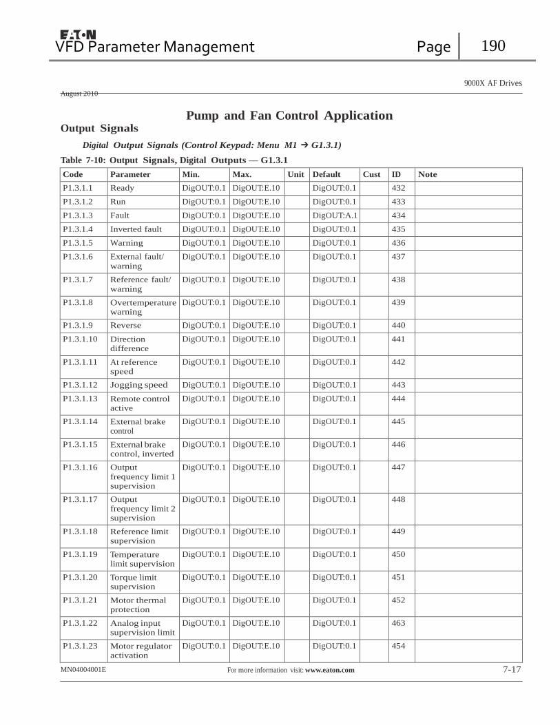
VFD Parameter Management Page 190
9000X AF Drives
August 2010
Output Signals Pump and Fan Control Application
Digital Output Signals (Control Keypad: Menu M1 ➔ G1.3.1)
Table 7-10: Output Signals, Digital Outputs — G1.3.1
Code Parameter Min. Max. Unit Default Cust ID Note
P1.3.1.1 Ready DigOUT:0.1 DigOUT:E.10 DigOUT:0.1 432
P1.3.1.2 Run DigOUT:0.1 DigOUT:E.10 DigOUT:0.1 433
P1.3.1.3 Fault DigOUT:0.1 DigOUT:E.10 DigOUT:A.1 434
P1.3.1.4 Inverted fault DigOUT:0.1 DigOUT:E.10 DigOUT:0.1 435
P1.3.1.5 Warning DigOUT:0.1 DigOUT:E.10 DigOUT:0.1 436
P1.3.1.6 External fault/
warning DigOUT:0.1 DigOUT:E.10 DigOUT:0.1 437
P1.3.1.7 Reference fault/ warning
DigOUT:0.1 DigOUT:E.10 DigOUT:0.1 438
P1.3.1.8 Overtemperature warning
DigOUT:0.1 DigOUT:E.10 DigOUT:0.1 439
P1.3.1.9 Reverse DigOUT:0.1 DigOUT:E.10 DigOUT:0.1 440
P1.3.1.10 Direction difference
DigOUT:0.1 DigOUT:E.10 DigOUT:0.1 441
P1.3.1.11 At reference speed
DigOUT:0.1 DigOUT:E.10 DigOUT:0.1 442
P1.3.1.12 Jogging speed DigOUT:0.1 DigOUT:E.10 DigOUT:0.1 443
P1.3.1.13 Remote control active
DigOUT:0.1 DigOUT:E.10 DigOUT:0.1 444
P1.3.1.14 External brake control
DigOUT:0.1 DigOUT:E.10 DigOUT:0.1 445
P1.3.1.15 External brake control, inverted
DigOUT:0.1 DigOUT:E.10 DigOUT:0.1 446
P1.3.1.16 Output
frequency limit 1 supervision
DigOUT:0.1 DigOUT:E.10 DigOUT:0.1 447
P1.3.1.17 Output frequency limit 2 supervision
DigOUT:0.1 DigOUT:E.10 DigOUT:0.1 448
P1.3.1.18 Reference limit supervision
DigOUT:0.1 DigOUT:E.10 DigOUT:0.1 449
P1.3.1.19 Temperature limit supervision
DigOUT:0.1 DigOUT:E.10 DigOUT:0.1 450
P1.3.1.20 Torque limit supervision
DigOUT:0.1 DigOUT:E.10 DigOUT:0.1 451
P1.3.1.21 Motor thermal protection
DigOUT:0.1 DigOUT:E.10 DigOUT:0.1 452
P1.3.1.22 Analog input supervision limit
DigOUT:0.1 DigOUT:E.10 DigOUT:0.1 463
P1.3.1.23 Motor regulator activation
DigOUT:0.1 DigOUT:E.10 DigOUT:0.1 454
MN04004001E For more information visit: www.eaton.com 7-17

VFD Parameter Management Page 191
9000X AF Drives
August 2010
Pump and Fan Control Application
Table 7-10: Output Signals, Digital Outputs — G1.3.1 (Continued)
Code Parameter Min. Max. Unit Default Cust ID Note
P1.3.1.24 Fieldbus digital input 1
DigOUT:0.1 DigOUT:E.10 DigOUT:0.1 455
P1.3.1.25 Fieldbus digital input 2
DigOUT:0.1 DigOUT:E.10 DigOUT:0.1 456
P1.3.1.26 Fieldbus digital input 3
DigOUT:0.1 DigOUT:E.10 DigOUT:0.1 457
P1.3.1.27 Autochange 1/ Aux 1 control
DigOUT:0.1 DigOUT:E.10 DigOUT:B.1 458
P1.3.1.28 Autochange 2/ Aux 2 control
DigOUT:0.1 DigOUT:E.10 DigOUT:B.2 459
P1.3.1.29 Autochange 3/ Aux 3 control
DigOUT:0.1 DigOUT:E.10 DigOUT:0.1 460
P1.3.1.30 Autochange 4/ Aux 4 control
DigOUT:0.1 DigOUT:E.10 DigOUT:0.1 461
P1.3.1.31 Autochange 5 DigOUT:0.1 DigOUT:E.10 DigOUT:0.1 462
Limit Settings (Control Keypad: Menu M1 ➔ G1.3.2)
Table 7-11: Output Signals, Limit Settings — G1.3.2
Code Parameter Min. Max. Unit Default Cust ID Note
P1.3.2.1 Output frequency limit 1 supervision
0 2 0 315 0 = No limit 1 = Low limit supervision 2 = High limit supervision
P1.3.2.2 Output freq. limit 1; Supervised value
0.00 P1.1.2 Hz 0.00 316
P1.3.2.3 Output frequency limit 2 supervision
0 2 0 346 0 = No limit 1 = Low limit supervision 2 = High limit supervision
P1.3.2.4 Output freq. limit 2; Supervised value
0.00 P1.1.2 Hz 0.00 347
P1.3.2.5 Torque limit supervision
0 2 0 348 0 = Not used
1 = Low limit supervision 2 = High limit supervision
P1.3.2.6 Torque limit supervision value
0.0 300.0 % 100.0 349
P1.3.2.7 Reference limit supervision
0 2 0 350 0 = Not used 1 = Low limit 2 = High limit
P1.3.2.8 Reference limit supervision value
0.0 100.0 % 0.0 351
P1.3.2.9 External brake-off delay
0.0 100.0 s 0.5 352
P1.3.2.10 External brake-on delay
0.0 100.0 s 1.5 353
P1.3.2.11 FC temperature supervision
0 2 0 354 0 = Not used 1 = Low limit 2 = High limit
7-18 For more information visit: www.eaton.com MN04004001E
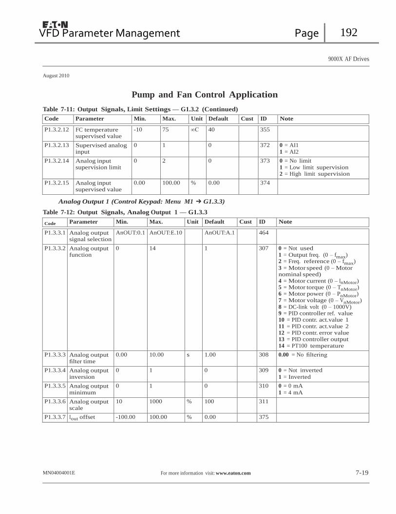
VFD Parameter Management Page 192
9000X AF Drives
August 2010
Pump and Fan Control Application
Table 7-11: Output Signals, Limit Settings — G1.3.2 (Continued)
Code Parameter Min. Max. Unit Default Cust ID Note
P1.3.2.12 FC temperature supervised value
-10 75 ∞C 40 355
P1.3.2.13 Supervised analog input
0 1 0 372 0 = AI1 1 = AI2
P1.3.2.14 Analog input supervision limit
0 2 0 373 0 = No limit
1 = Low limit supervision 2 = High limit supervision
P1.3.2.15 Analog input supervised value
0.00 100.00 % 0.00 374
Analog Output 1 (Control Keypad: Menu M1 ➔ G1.3.3)
Table 7-12: Output Signals, Analog Output 1 — G1.3.3
Code Parameter Min. Max. Unit Default Cust ID Note
P1.3.3.1 Analog output signal selection
AnOUT:0.1 AnOUT:E.10 AnOUT:A.1 464
P1.3.3.2 Analog output function
0 14 1 307 0 = Not used 1 = Output freq. (0 – fmax) 2 = Freq. reference (0 – fmax) 3 = Motor speed (0 – Motor nominal speed) 4 = Motor current (0 – InMotor) 5 = Motor torque (0 – TnMotor) 6 = Motor power (0 – PnMotor) 7 = Motor voltage (0 – VnMotor) 8 = DC-link volt (0 – 1000V) 9 = PID controller ref. value 10 = PID contr. act.value 1 11 = PID contr. act.value 2 12 = PID contr. error value 13 = PID controller output 14 = PT100 temperature
P1.3.3.3 Analog output filter time
0.00 10.00 s 1.00 308 0.00 = No filtering
P1.3.3.4 Analog output inversion
0 1 0 309 0 = Not inverted
1 = Inverted
P1.3.3.5 Analog output minimum
0 1 0 310 0 = 0 mA
1 = 4 mA
P1.3.3.6 Analog output scale
10 1000 % 100 311
P1.3.3.7 Iout offset -100.00 100.00 % 0.00 375
MN04004001E For more information visit: www.eaton.com 7-19

VFD Parameter Management Page 193
9000X AF Drives
August 2010
Pump and Fan Control Application
Analog Output 2 (Control Keypad: Menu M1 ➔ G1.3.4)
Table 7-13: Output Signals, Analog Output 2 — G1.3.4
Code Parameter Min. Max. Unit Default Cust ID Note
P1.3.4.1 Analog output 2 signal selection
AnOUT:01 AnOUT:E.10 AnOUT:0.1 471
P1.3.4.2 Analog output 2 function
0 14 0 472 See P1.3.3.2
P1.3.4.3 Analog output 2 filter time
0.00 10.00 s 1.00 473 0.00 = No filtering
P1.3.4.4 Analog output 2 inversion
0 1 0 474 0 = Not inverted 1 = Inverted
P1.3.4.5 Analog output 2 minimum
0 1 0 475 0 = 0 mA 1 = 4 mA
P1.3.4.6 Analog output 2 scale
10 1000 % 100 476
P1.3.4.7 Analog output 2 offset
-100.00 100.00 % 0.00 477
Analog Output 3 (Control Keypad: Menu M1 ➔ G1.3.5)
Table 7-14: Output Signals, Analog Output 3 — G1.3.5
Code Parameter Min. Max. Unit Default Cust ID Note
P1.3.5.1 Analog output 3 signal selection
AnOUT:01 AnOUT:E.10 AnOUT:0.1 478
P1.3.5.2 Analog output 3 function
0 14 0 479 See P1.3.3.2
P1.3.5.3 Analog output 3 filter time
0.00 10.00 s 1.00 480 0.00 = No filtering
P1.3.5.4 Analog output 3 inversion
0 1 0 481 0 = Not inverted 1 = Inverted
P1.3.5.5 Analog output 3 minimum
0 1 0 482 0 = 0 mA 1 = 4 mA
P1.3.5.6 Analog output 3 scale
10 1000 % 100 483
P1.3.5.7 Analog output 3 offset
-100.00 100.00 % 0.00 484
7-20 For more information visit: www.eaton.com MN04004001E

VFD Parameter Management Page 194
9000X AF Drives
August 2010
Pump and Fan Control Application
Drive Control Parameters (Control Keypad: Menu M1 ➔ G1.4)
Table 7-15: Drive Control Parameters — G1.4
Code Parameter Min. Max. Unit Default Cust ID Note
P1.4.1 Ramp 1 shape 0.0 10.0 s 0.0 500 0.00 = Linear >0.00 = S-curve ramp time
P1.4.2 Ramp 2 shape 0.0 10.0 s 0.0 501 0.00 = Linear >0.00 = S-curve ramp time
P1.4.3 Acceleration time 2 0.1 3000.0 s 10.0 502 P1.4.4 Deceleration time 2 0.1 3000.0 s 10.0 503 P1.4.5 Brake chopper 0 4 0 504 0 = Disabled
1 = Used when running 2 = External brake chopper 3 = Used when stopped/running 4 = Used when running (no testing)
P1.4.6 Start mode 0 1 0 505 0 = Ramp 1 = Flying start
P1.4.7 Stop mode 0 3 1 506 0 = Coasting 1 = Ramp 2 = Ramp+Run enable coast 3 = Coast+Run enable ramp
P1.4.8 DC braking current 0.4 x IH 2 x IH A IH 507 P1.4.9 DC braking time at
stop 0.00 600.00 s 0.00 508 0.00 = DC brake is off at stop
P1.4.10 Frequency to start DC braking during ramp stop
0.10 10.00 Hz 1.50 515
P1.4.11 DC braking time at start
0.00 600.00 s 0.00 516 0.00 = DC brake is off at start
P1.4.12 Flux brake 0 1 0 520 0 = Off 1 = On
P1.4.13 Flux braking current 0.4 x IH 2 x IH A IH 519
MN04004001E For more information visit: www.eaton.com 7-21

VFD Parameter Management Page 195
9000X AF Drives
August 2010
Pump and Fan Control Application Skip Frequencies (Control Keypad: Menu M1 ➔ G1.5)
Table 7-16: Skip Frequencies— G1.5
Code Parameter Min. Max. Unit Default Cust ID Note
P1.5.1 Skip frequency range 1 low limit
0.0 P1.5.2 Hz 0.00 509
P1.5.2 Skip frequency range 1 high limit
P1.5.1 320.00 Hz 0.00 510 0.00 = Skip frequency range 1 not used
P1.5.3 Skip frequency range 2 low limit
0.00 P1.5.4 Hz 0.00 511
P1.5.4 Skip frequency range 2 high limit
P1.5.3 320.00 Hz 0.00 512 0.00 = Skip frequency range 2 not used
P1.5.5 Skip frequency range 3 low limit
0.00 P1.5.6 Hz 0.00 513
P1.5.6 Skip frequency range 3 high limit
P1.5.5 320.00 Hz 0.00 514 0.00 = Skip frequency range 3 not used
P1.5.7 Prohibit acc./dec. ramp
0.1 10.0 1.0 518 Multiplier for ramp time in skip frequency range, e.g. 0.1 – 10% of normal ramp time
Motor Control Parameters (Control Keypad: Menu M1 ➔ G1.6)
Table 7-17: Motor Control Parameters — G1.6
Code Parameter Min. Max. Unit Default Cust ID Note
P1.6.1 Motor control mode 0 1 0 600 0 = Frequency control 1 = Speed control
P1.6.2 V/Hz optimization 0 1 0 109 0 = Not used 1 = Automatic torque boost
P1.6.3 V/Hz ratio selection 0 3 0 108 0 = Linear 1 = Squared 2 = Programmable 3 = Linear with flux optim.
P1.6.4 Field weakening point
8.00 320.00 Hz 60.00 602
P1.6.5 Voltage at field weakening point
10.00 200.00 % 100.00 603 n% x VnMotor
P1.6.6 V/Hz curve
midpoint frequency 0.00 P1.6.4 Hz 60.00 604
P1.6.7 V/Hz curve midpoint voltage
0.00 P1.6.5 % 100.00 605 n% x VnMotor
Parameter max. value = par. 1.6.5
P1.6.8 Output voltage at zero frequency
0.00 40.00 % 1.30 606 n% x VnMotor
P1.6.9 Switching frequency
1.0 Varies kHz Varies 601 See Table 8-12 on Page 8-57 for exact values
P1.6.10 Overvoltage controller
0 2 1 607 0 = Not used 1 = Used (no ramping) 2 = Used (ramping)
P1.6.11 Undervoltage controller
0 1 1 608 0 = Not used 1 = Used
7-22 For more information visit: www.eaton.com MN04004001E

VFD Parameter Management Page 196
9000X AF Drives
August 2010
Pump and Fan Control Application Protections (Control keypad: Menu M1 ➔ G1.7)
Table 7-18: Protections — G1.7
Code Parameter Min. Max. Unit Default Cust ID Note
P1.7.1 Response to reference fault
0 5 0 700 0 = No response
1 = Warning 2 = Warning+Previous Freq. 3 = Warning+Preset Freq P1.7.2 4 = Fault, stop acc. to P1.4.7 5 = Fault, stop by coasting
P1.7.2 4mA reference fault frequency
0.00 P1.1.2 Hz 0.00 728
P1.7.3 Response to external fault
0 3 2 701 0 = No response 1 = Warning 2 = Fault, stop per P1.4.7 3 = Fault, stop by coasting
P1.7.4 Input phase supervision
0 3 3 730 See P1.7.3
P1.7.5 Response to undervoltage fault
0 1 0 727 0 = Fault Stored
1 = No History
P1.7.6 Output phase supervision
0 3 2 702 See P1.7.3
P1.7.7 Ground fault protection
0 3 2 703 See P1.7.3
P1.7.8 Thermal protection of the motor
0 3 2 704 See P1.7.3
P1.7.9 Motor ambient temperature factor
-100.0 100.0 % 0.0 705
P1.7.10 Motor cooling
factor at zero speed 0.0 150.0 % 40.0 706 As a % of In motor
P1.7.11 Motor thermal time constant
1 200 min 45 707
P1.7.12 Motor duty cycle 0 100 % 100 708 P1.7.13 Stall protection 0 3 1 709 See P1.7.3
P1.7.14 Stall current 0.1 InMotor
x 2 A IL 710
P1.7.15 Stall time limit 1.00 120.00 s 15.00 711 P1.7.16 Stall frequency limit 1.0 P1.1.2 Hz 25.00 712 P1.7.17 Underload
protection 0 3 0 713 See P1.7.3
P1.7.18 Underload protect. fnom torque
10 150.0 % 50.0 714
P1.7.19 Underload protect. fo torque
5.0 150.0 % 10.0 715
P1.7.20 Underload protection time limit
2.00 600.00 s 20.00 716
P1.7.21 Response to thermistor fault
0 3 2 732 See P1.7.3
MN04004001E For more information visit: www.eaton.com 7-23
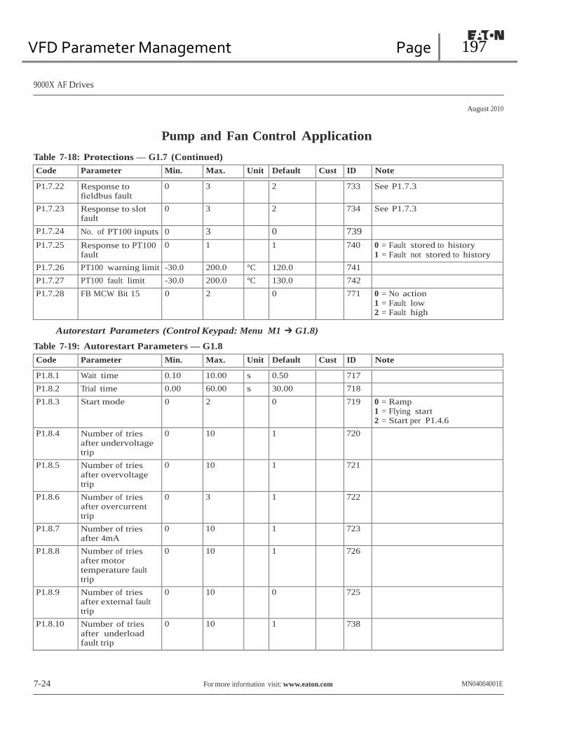
VFD Parameter Management Page 197
9000X AF Drives
August 2010
Pump and Fan Control Application
Table 7-18: Protections — G1.7 (Continued)
Code Parameter Min. Max. Unit Default Cust ID Note
P1.7.22 Response to fieldbus fault
0 3 2 733 See P1.7.3
P1.7.23 Response to slot fault
0 3 2 734 See P1.7.3
P1.7.24 No. of PT100 inputs 0 3 0 739 P1.7.25 Response to PT100
fault 0 1 1 740 0 = Fault stored to history
1 = Fault not stored to history
P1.7.26 PT100 warning limit -30.0 200.0 °C 120.0 741 P1.7.27 PT100 fault limit -30.0 200.0 °C 130.0 742 P1.7.28 FB MCW Bit 15 0 2 0 771 0 = No action
1 = Fault low 2 = Fault high
Autorestart Parameters (Control Keypad: Menu M1 ➔ G1.8)
Table 7-19: Autorestart Parameters — G1.8
Code Parameter Min. Max. Unit Default Cust ID Note
P1.8.1 Wait time 0.10 10.00 s 0.50 717 P1.8.2 Trial time 0.00 60.00 s 30.00 718 P1.8.3 Start mode 0 2 0 719 0 = Ramp
1 = Flying start 2 = Start per P1.4.6
P1.8.4 Number of tries after undervoltage trip
0 10 1 720
P1.8.5 Number of tries after overvoltage trip
0 10 1 721
P1.8.6 Number of tries after overcurrent trip
0 3 1 722
P1.8.7 Number of tries after 4mA
0 10 1 723
P1.8.8 Number of tries after motor temperature fault trip
0 10 1 726
P1.8.9 Number of tries after external fault trip
0 10 0 725
P1.8.10 Number of tries after underload fault trip
0 10 1 738
7-24 For more information visit: www.eaton.com MN04004001E

VFD Parameter Management Page 198
9000X AF Drives
August 2010
Pump and Fan Control Application Pump and Fan Control Parameters (Control Keypad: Menu M1 ➔ G1.9)
Table 7-20: Pump and Fan Control Parameters — G1.9
Code Parameter Min. Max. Unit Default Cust ID Note
P1.9.1 Number of auxiliary drives
0 4 0 1001
P1.9.2 Start frequency. auxiliary drive 1
P1.9.3 320.00 Hz 61.00 1002
P1.9.3 Stop frequency. auxiliary drive 1
P1.1.1 P1.9.2 Hz 10.00 1003
P1.9.4 Start frequency. auxiliary drive 2
P1.9.5 320.00 Hz 61.00 1004
P1.9.5 Stop frequency. auxiliary drive 2
P1.1.1 P1.9.4 Hz 10.00 1005
P1.9.6 Start frequency. auxiliary drive 3
P1.9.7 320.00 Hz 61.00 1006
P1.9.7 Stop frequency. auxiliary drive 3
P1.1.1 P1.9.6 Hz 10.00 1007
P1.9.8 Start frequency. auxiliary drive 4
P1.9.9 320.00 Hz 61.00 1008
P1.9.9 Stop frequency. auxiliary drive 4
P1.1.1 P1.9.8 Hz 10.00 1009
P1.9.10 Start delay. auxiliary drives
0.0 300.0 s 4.0 1010
P1.9.11 Stop delay. auxiliary drives
0.0 300.0 s 2.0 1011
P1.9.12 Reference step. auxiliary drive 1
0.0 100.0 % 0.0 1012
P1.9.13 Reference step. auxiliary drive 2
0.0 100.0 % 0.0 1013
P1.9.14 Reference step. auxiliary drive 3
0.0 100.0 % 0.0 1014
P1.9.15 Reference step. auxiliary drive 4
0.0 100.0 % 0.0 1015
P1.9.16 PID controller bypass
0 1 0 1020 1 = PID contr. bypassed
P1.9.17 Analog input selection for input pressure measurement
0 5 0 1021 0 = Not used 1 = AI1 2 = AI2 3 = AI3 4 = AI4 5 = Fieldbus signal
P1.9.18 Input pressure high limit
0.0 100.0 % 30.00 1022
P1.9.19 Input pressure low limit
0.0 100.0 % 20.00 1023
P1.9.20 Output pressure drop
0.0 100.0 % 30.00 1024
P1.9.21 Frequency drop delay
0.0 300.0 s 0.0 1025 0.0 = No delay
300.0 = No frequency drop
MN04004001E For more information visit: www.eaton.com 7-25
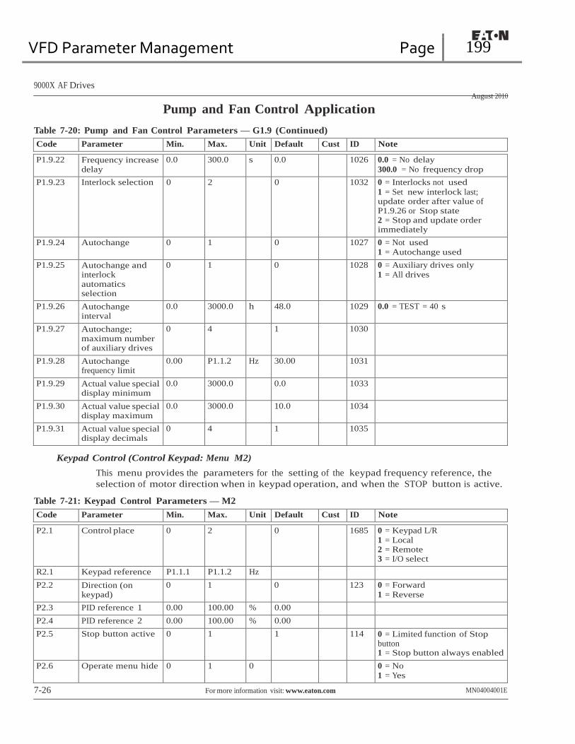
VFD Parameter Management Page 199
9000X AF Drives
August 2010
Pump and Fan Control Application
Table 7-20: Pump and Fan Control Parameters — G1.9 (Continued)
Code Parameter Min. Max. Unit Default Cust ID Note
P1.9.22 Frequency increase delay
0.0 300.0 s 0.0 1026 0.0 = No delay
300.0 = No frequency drop
P1.9.23 Interlock selection 0 2 0 1032 0 = Interlocks not used
1 = Set new interlock last; update order after value of P1.9.26 or Stop state 2 = Stop and update order immediately
P1.9.24 Autochange 0 1 0 1027 0 = Not used 1 = Autochange used
P1.9.25 Autochange and interlock automatics selection
0 1 0 1028 0 = Auxiliary drives only 1 = All drives
P1.9.26 Autochange interval
0.0 3000.0 h 48.0 1029 0.0 = TEST = 40 s
P1.9.27 Autochange; maximum number of auxiliary drives
0 4 1 1030
P1.9.28 Autochange frequency limit
0.00 P1.1.2 Hz 30.00 1031
P1.9.29 Actual value special display minimum
0.0 3000.0 0.0 1033
P1.9.30 Actual value special display maximum
0.0 3000.0 10.0 1034
P1.9.31 Actual value special display decimals
0 4 1 1035
Keypad Control (Control Keypad: Menu M2)
This menu provides the parameters for the setting of the keypad frequency reference, the
selection of motor direction when in keypad operation, and when the STOP button is active.
Table 7-21: Keypad Control Parameters — M2
Code Parameter Min. Max. Unit Default Cust ID Note
P2.1 Control place 0 2 0 1685 0 = Keypad L/R 1 = Local 2 = Remote 3 = I/O select
R2.1 Keypad reference P1.1.1 P1.1.2 Hz P2.2 Direction (on
keypad) 0 1 0 123 0 = Forward
1 = Reverse
P2.3 PID reference 1 0.00 100.00 % 0.00 P2.4 PID reference 2 0.00 100.00 % 0.00 P2.5 Stop button active 0 1 1 114 0 = Limited function of Stop
button 1 = Stop button always enabled
P2.6 Operate menu hide 0 1 0 0 = No 1 = Yes
7-26 For more information visit: www.eaton.com MN04004001E

VFD Parameter Management Page 200
9000X AF Drives
August 2010
Pump and Fan Control Application
Menus — M3 to M6
Menus M3 to M6 provide information on the Active Faults, Fault History, System Menu
settings and the Expander Board setup. These menu items are explained in detail in
Chapter 5 of the 9000X AF Drives User Manual.
Monitoring Menu — M7
The monitored items are the actual values of parameters and signals as well as the
status and measurements of other elements. Monitored items cannot be edited.
See the 9000X AF Drives User Manual, Chapter 5 — Menu information item M7, for
more information.
Note: Local control is always frequency control mode unless PID is selected for the local
reference. In remote, frequency mode is selected with DIN6 unless PID is selected for
the remote reference. PC Control is always frequency mode.
MN04004001E For more information visit: www.eaton.com 7-27

VFD Parameter Management Page 201
9000X AF Drives
August 2010
7-28 For more information visit: www.eaton.com MN04004001E
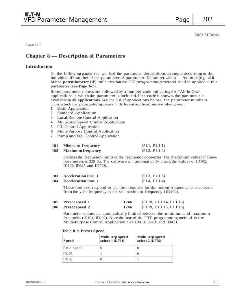
VFD Parameter Management Page 202
9000X AF Drives
August 2010
Chapter 8 — Description of Parameters Introduction
On the following pages you will find the parameter descriptions arranged according to the individual ID number of the parameter. A parameter ID number with a footnote (e.g. 418
Motor potentiometer UP) indicates that the TTF programming method shall be applied to this parameter (see Page 6-3).
Some parameter names are followed by a number code indicating the “All-in-One” applications in which the parameter is included. If no code is shown, the parameter is available in all applications. See the list of applications below. The parameter numbers under which the parameter appears in different applications are also given. 1 Basic Application
2 Standard Application
3 Local/Remote Control Application
4 Multi-Step Speed Control Application
5 PID Control Application
6 Multi-Purpose Control Application
7 Pump and Fan Control Application
101 Minimum frequency (P1.1, P1.1.1) 102 Maximum frequency (P1.2, P1.1.2)
Defines the frequency limits of the frequency converter. The maximum value for these parameters is 320 Hz. The software will automatically check the values of ID105, ID106, ID315 and ID728.
103 Acceleration time 1 (P1.3, P1.1.3) 104 Deceleration time 1 (P1.4, P1.1.4)
These limits correspond to the time required for the output frequency to accelerate from the zero frequency to the set maximum frequency (ID102).
105 Preset speed 1 1246 (P1.18, P1.1.14, P1.1.15) 106 Preset speed 2 1246 (P1.19, P1.1.15, P1.1.16)
Parameter values are automatically limited between the minimum and maximum frequencies (ID101, ID102). Note the use of the TTF-programming method in the Multi-Purpose Control Application. See ID419, ID420 and ID421.
Table 8-1: Preset Speed
Multi-step speed
Multi-step speed
Speed select 1 (DIN4) select 2 (DIN5)
Basic speed 0 0
ID105 1 0
ID106 0 1
MN04004001E For more information visit: www.eaton.com 8-1

VFD Parameter Management Page 203
9000X AF Drives
August 2010
Description of Parameters
107 Current limit (P1.5, P1.1.5)
This parameter determines the maximum motor current from the frequency converter. The parameter value range differs from size to size.
108 V/Hz ratio selection 234567 (P1.6.3)
Linear:
0 The voltage of the motor changes linearly with the frequency in the constant flux area from 0 Hz to the field weakening point where the nominal voltage is supplied to the motor. A linear V/Hz ratio should be used in constant torque applications. This default setting should be used if there is no special need for another setting.
Squared:
1 The voltage of the motor changes following a squared curve form with the frequency in the area from 0 Hz to the field weakening point where the nominal voltage is supplied to the motor. The motor runs under magnetized below the field weakening point and produces less torque and electromechanical noise. A squared V/Hz ratio can be used in applications where the torque demand of the load is proportional to the square of the speed, e.g. in centrifugal fans and pumps.
U[V]
Un ID603 Default: Nominal
Voltage of the Motor Field Weakening Point
Linear
Squared Default: Nominal Frequency of the Motor
f [Hz]
Figure 8-1: Linear and Squared Change of Motor Voltage
Programmable V/Hz curve:
2 The V/Hz curve can be programmed with three different points. A programmable V/Hz curve can be used if the other settings do not satisfy the needs of the application.
8-2 For more information visit: www.eaton.com MN04004001E

VFD Parameter Management Page 204
9000X AF Drives
August 2010
Description of Parameters
U[V]
Un
ID603 Default: Nominal Voltage of the Motor
Field Weakening
Point
ID605
(Default 10%)
ID606
(Default 1.3%)
ID604
(Default 5 Hz)
Default: Nominal
Frequency of the
Motor
ID602
f[Hz]
Figure 8-2: Programmable V/Hz Curve
Linear with flux optimization:
3 The frequency converter starts to search for the minimum motor current in order to save energy, lower the disturbance level and the noise. This function can be used in applications with constant motor load, such as fans, pumps, etc.
109 V/Hz optimization (P1.13, P1.6.2)
Automatic torque boost
Example:
The voltage to the motor changes automatically which makes the motor produce sufficient torque to start and run at low frequencies. The voltage increase depends on the motor type and power. Automatic torque boost can be used in applications where starting torque due to starting friction is high, e.g. in conveyors.
What changes are required to start the load from 0 Hz?
● First set the motor nominal values (Parameter group 1.1).
Option 1: Activate the Automatic torque boost.
Option 2: Programmable V/Hz curve
To obtain the required torque, the zero point voltage and midpoint voltage/frequency (in parameter group 1.6) need to be set, so that the motor can draw enough current at the low frequencies. First set parameter ID108 to Programmable V/Hz curve (value 2). Increase the zero point voltage (ID606) to get enough current at zero speed. Then set the midpoint voltage (ID605) to 1.4142*ID606 and the midpoint frequency (ID604) to value ID606/100%*ID111.
Note: In high torque — low speed applications — it is likely that the motor will
overheat. If the motor has to run a prolonged time under these conditions,
special attention must be paid to cooling the motor. Use external cooling for
the motor if the temperature tends to rise too high.
MN04004001E For more information visit: www.eaton.com 8-3

VFD Parameter Management Page 205
9000X AF Drives
August 2010
Description of Parameters
110 Nominal voltage of the motor (P1.6, P1.1.6)
Find this value Vn on the rating plate of the motor. This parameter sets the voltage at the field weakening point (ID603) to 100% * VnMotor.
111 Nominal frequency of the motor (P1.7, P1.1.7)
Find this value fn on the rating plate of the motor. This parameter sets the field weakening point (ID602) to the same value.
112 Nominal speed of the motor (P1.8, P1.1.8)
Find this value nn on the rating plate of the motor.
113 Nominal current of the motor (P1.9, P1.1.9)
Find this value ln on the rating plate of the motor.
118 PID controller gain 57 (P1.1.12)
This parameter defines the gain of the PID controller. If the value of the parameter is set to 100% a change of 10% in the error value causes the controller output to change by 10%. If the parameter value is set to 0 the PID controller operates as ID-controller. See the examples on Page 8-5.
119 PID controller I-time 57 (P1.1.13)
ID119 defines the integration time of the PID controller. If this parameter is set to 1.00 second, a change of 10% in the error value causes the controller output to change by 10.00%/s. If the parameter value is set to 0.00 s the PID controller will operate as PD controller. See the examples on Page 8-5.
120 Motor Power Factor (P1.10, P1.1.10)
Find this value “Power Factor” on the rating plate of the motor.
124 Jogging speed reference 34567 (P1.1.14, P1.1.15, P1.1.19)
Defines the jogging speed selected with the DIN3 digital input which can be programmed for Jogging speed. See parameter ID301.
This parameter’s value is automatically limited between minimum and maximum frequency (ID101 and ID102).
126 Preset speed 3 46 (P1.1.17) 127 Preset speed 4 46 (P1.1.18) 128 Preset speed 5 46 (P1.1.19) 129 Preset speed 6 46 (P1.1.20) 130 Preset speed 7 46 (P1.1.21)
These parameter values define the Multi-step speeds selected with the DIN3, DIN4, DIN5 and DIN6 digital inputs. See also parameters ID105 and ID106.
These parameter values are automatically limited between minimum and maximum frequency (ID101 and ID102).
8-4 For more information visit: www.eaton.com MN04004001E
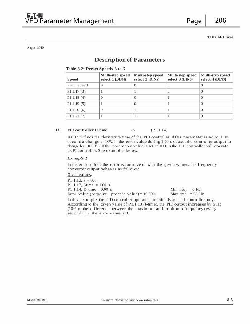
VFD Parameter Management Page 206
9000X AF Drives
August 2010
Description of Parameters
Table 8-2: Preset Speeds 3 to 7
Speed
Multi-step speed
select 1 (DIN4) Multi-step speed
select 2 (DIN5) Multi-step speed
select 3 (DIN6) Multi-step speed
select 4 (DIN3)
Basic speed 0 0 0 0
P1.1.17 (3) 1 1 0 0
P1.1.18 (4) 0 0 1 0
P1.1.19 (5) 1 0 1 0
P1.1.20 (6) 0 1 1 0
P1.1.21 (7) 1 1 1 0
132 PID controller D-time 57 (P1.1.14)
ID132 defines the derivative time of the PID controller. If this parameter is set to 1.00 second a change of 10% in the error value during 1.00 s causes the controller output to change by 10.00%. If the parameter value is set to 0.00 s the PID controller will operate as PI controller. See examples below.
Example 1:
In order to reduce the error value to zero, with the given values, the frequency converter output behaves as follows:
Given values:
P1.1.12, P = 0%
P1.1.13, I-time = 1.00 s P1.1.14, D-time = 0.00 s Min freq. = 0 Hz Error value (setpoint – process value) = 10.00% Max freq. = 60 Hz
In this example, the PID controller operates practically as an I-controller only. According to the given value of P1.1.13 (I-time), the PID output increases by 5 Hz (10% of the difference between the maximum and minimum frequency) every second until the error value is 0.
MN04004001E For more information visit: www.eaton.com 8-5

VFD Parameter Management Page 207
9000X AF Drives
August 2010
Description of Parameters
Hz
PID Output
Error Value
10%
Error = 10%
1s
10%
10%
10% I-Part = 5 Hz/s
I-Part = 5 Hz/s
I-Part = 5 Hz/s
I-Part = 5 Hz/s
I-Part = 5 Hz/s
t
Figure 8-3: PID Controller Function as I-Controller
Example 2:
Given values:
P1.1.12, P = 100% P1.1.13, I-time = 1.00 s P1.1.14, D-time = 1.00 s Min freq. = 0 Hz Error value (setpoint – process value) = ±10% Max freq. = 60 Hz
As the power is switched on, the system detects the difference between the setpoint and the actual process value and starts to either raise or decrease (in case the error value is negative) the PID output according to the I-time. Once the difference between the setpoint and the process value has been reduced to 0, the output is reduced by the amount corresponding to the value of P1.1.13.
In case the error value is negative, the frequency converter reacts reducing the output correspondingly. See Figure 8-4.
Hz
PID Output
Error Value
D-part
D-part
D-part
P-part = 5 Hz Error = 10%
Error = -10%
P-part = -5 Hz t
Figure 8-4: PID Output Curve with the Values of Example 2

VFD Parameter Management Page 208
9000X AF Drives
August 2010
Description of Parameters
Example 3:
Given values:
P1.1.12, P = 100% P1.1.13, I-time = 0.00 s P1.1.14, D-time = 1.00 s Min freq. = 0 Hz Error value (setpoint – process value) = ±10%/s Max freq. = 60 Hz
As the error value increases, the PID output also increases according to the set values (D-time = 1.00s)
Hz PID Output
D-part = 10% = 5.00 Hz
Error Value
D-part = -10% = -5.00 Hz
P-part = 100% *PID error = 5.000 Hz/s
10%
1.00 s t
Figure 8-5: PID Output Curve with the Values of Example 3
133 Preset speed 8 4 (P1.1.22) 134 Preset speed 9 4 (P1.1.23) 135 Preset speed 10 4 (P1.1.24) 136 Preset speed 11 4 (P1.1.25) 137 Preset speed 12 4 (P1.1.26) 138 Preset speed 13 4 (P1.1.27) 139 Preset speed 14 4 (P1.1.28) 140 Preset speed 15 4 (P1.1.29)
Table 8-3: Multi-Step Speed Selections with Digital Inputs DIN3, DIN4, DIN5 and DIN6
Speed
Multi-step speed
select 1 (DIN4) Multi-step speed
select 2 (DIN5) Multi-step speed
select 3 (DIN6) Multi-step speed
select 4 (DIN3)
P1.1.22 (8) 0 0 0 1
P1.1.23 (9) 1 0 0 1
P1.1.24 (10) 0 1 0 1
P1.1.25 (11) 1 1 0 1
P1.1.26 (12) 0 0 1 1
P1.1.27 (13) 1 0 1 1
P1.1.28 (14) 0 1 1 1
P1.1.29 (15) 1 1 1 1
MN04004001E For more information visit: www.eaton.com 8-7

VFD Parameter Management Page 209
9000X AF Drives
August 2010
Description of Parameters 141 AI3 signal selection 567 (P1.2.38, P1.2.4.1)
Connect the AI3 signal to the analog input of your choice with this parameter. For more information, see Page 6-3, “Terminal to Function” (TTF) programming principle.
142 AI3 signal filter time 567 (P1.2.41, P1.2.4.2)
When this parameter is given a value greater than 0, the function that filters out disturbances from the incoming analog signal is activated. A long filtering time makes the regulation response slower. See ID324.
143 AI3 signal range 567 (P1.2.39, P1.2.4.3)
With this parameter you can select the AI3 signal range.
Table 8-4: Selections for ID143
Application
5
6
7 Select
0 0 – 100% 0 – 100% 0 – 100%
1 20 – 100% 20 – 100% 20 – 100%
2 — -10 – +10V Customized
3 — Customized
144 AI3 custom setting minimum 67 (P1.2.4.4) 145 AI3 custom setting maximum 67 (P1.2.4.5)
Set the custom minimum and maximum levels for the AI3 signal from 0 to 100%.
151
AI3 signal inversion
567
(P1.2.40, P1.2.4.6)
0 = No inversion 1 = Signal inverted
152
AI4 signal selection
567
(P1.2.42, P1.2.5.1)
See ID141.
153
AI4 filter time
567
(P1.2.45, P1.2.5.2)
See ID142.
154
AI4 signal range
567
(P1.2.43, P1.2.5.3)
See ID143.
155
AI4 custom setting minimum
67
(P1.2.5.4) 156 AI4 custom setting maximum 67 (P1.2.5.5)
See ID144 and ID145.
162
AI4 signal inversion
567
(P1.2.44, P1.2.5.6)
See ID151.
8-8 For more information visit: www.eaton.com MN04004001E
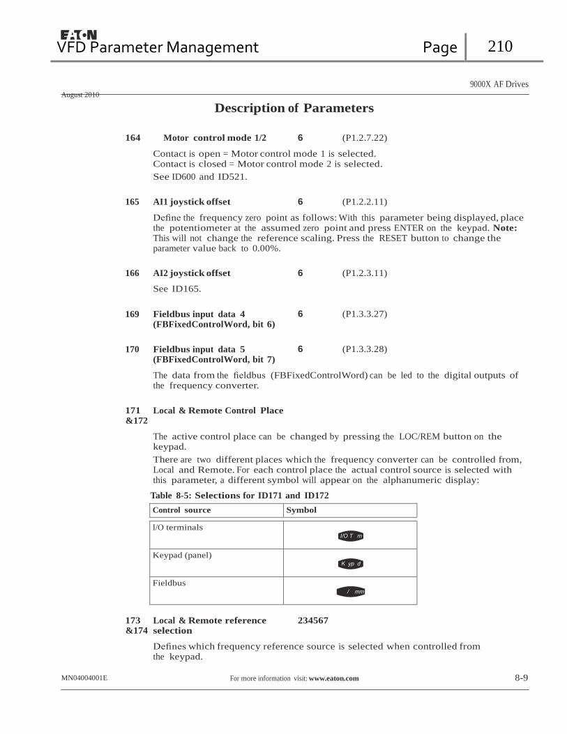
VFD Parameter Management Page 210
9000X AF Drives
August 2010
Description of Parameters
164 Motor control mode 1/2 6 (P1.2.7.22)
Contact is open = Motor control mode 1 is selected. Contact is closed = Motor control mode 2 is selected.
See ID600 and ID521.
165 AI1 joystick offset 6 (P1.2.2.11)
Define the frequency zero point as follows: With this parameter being displayed, place the potentiometer at the assumed zero point and press ENTER on the keypad. Note: This will not change the reference scaling. Press the RESET button to change the parameter value back to 0.00%.
166 AI2 joystick offset 6 (P1.2.3.11)
See ID165.
169 Fieldbus input data 4
(FBFixedControlWord, bit 6) 6 (P1.3.3.27)
170 Fieldbus input data 5
(FBFixedControlWord, bit 7) 6 (P1.3.3.28)
The data from the fieldbus (FBFixedControlWord) can be led to the digital outputs of the frequency converter.
171 &172
Local & Remote Control Place
The active control place can be changed by pressing the LOC/REM button on the keypad.
There are two different places which the frequency converter can be controlled from, Local and Remote. For each control place the actual control source is selected with this parameter, a different symbol will appear on the alphanumeric display:
Table 8-5: Selections for ID171 and ID172
Control source Symbol
I/O terminals
Keypad (panel)
Fieldbus
173 &174
Local & Remote reference selection
234567
Defines which frequency reference source is selected when controlled from the keypad.
MN04004001E For more information visit: www.eaton.com 8-9

VFD Parameter Management Page 211
9000X AF Drives
August 2010
Description of Parameters
Table 8-6: Selections for ID173, ID174 and ID175
Application
2 – 4
5
6
7 Select
0 Analog voltage ref. Terminals 2 – 3
Analog voltage ref. Terminals 2 – 3
Analog voltage ref. Terminals 2 – 3
Analog voltage ref. Terminals 2 – 3
1 Analog current ref. Terminals 4 – 5
Analog current ref. Terminals 4 – 5
Analog current ref. Terminals 4 – 5
Analog current ref. Terminals 4 – 5
2 Keypad reference
(Menu M2) AI3 AI1+AI2 AI3
3 Fieldbus reference
AI4 AI1 – AI2 AI4
4 Motor potentiometer (App #3 only)
Keypad reference (Menu M2)
AI2 – AI1 Keypad reference (Menu M2)
5 — Fieldbus reference
AI1 x AI2 Fieldbus reference
6 — Potentiometer ref. AI1 joystick Potentiometer ref.
7 — PID controller ref. AI2 joystick PID controller ref.
8 — — Keypad reference (Menu M2)
—
9 — — Fieldbus reference —
10 — — Potentiometer reference; controlled with DIN5 (TRUE = increase) and DIN6 (TRUE = decrease)
—
11 — — AI1 or AI2, whichever is lower
—
12 — — AI1 or AI2, whichever is greater
—
13 — — Max. frequency (recommended in torque control only)
—
14 — — AI1/AI2 selection —
FB Speed Reference
176 Force local 6 (P1.2.7.19)
Forces control place to I/O terminal.
177 Force remote 6 (P1.2.7.20) 300
Forces control place to keypad.
Start/Stop logic selection
2346
(P1.2.1, P1.2.1.1)
0 DIN1: closed contact = start forward DIN2: closed contact = start reverse
8-10 For more information visit: www.eaton.com MN04004001E

VFD Parameter Management Page 212
9000X AF Drives
August 2010
Description of Parameters
FWD Output
Frequency Stop Function
(ID506) = Coasting
t
REV
DIN1
DIN2
1 2 3
Figure 8-6: Start Forward/Start Reverse
The first selected direction has the highest priority.
When the DIN1 contact opens the direction of rotation starts to change.
If Start forward (DIN1) and Start reverse (DIN2) signals are active simultaneously the Start forward signal (DIN1) has priority.
1 DIN1: closed contact = start — open contact = stop DIN2: closed contact = reverse — open contact = forward, see Figure 8-7.
FWD Output
Frequency
Stop Function
(ID506) = Coasting
t
REV
DIN1
DIN2
Figure 8-7: Start, Stop and Reverse
MN04004001E For more information visit: www.eaton.com 8-11

VFD Parameter Management Page 213
9000X AF Drives
August 2010
Description of Parameters
2 DIN1: closed contact = start — open contact = stop DIN2: closed contact = start enabled — open contact = start disabled and drive stopped if running, see Figure 8-8.
3 3-wire connection (pulse control): DIN1: closed contact = start pulse DIN2: open contact = stop pulse (DIN3 can be programmed for reverse command), see Figure 8-8.
Output
Frequency Stop Function
(ID506) = Coasting
If Start and Stop pulses are
simultaneous the Stop pulse
overrides the Start pulse
t
REV
DIN1
Start
DIN2
Stop
Figure 8-8: Start Pulse/Stop Pulse
8-12 For more information visit: www.eaton.com MN04004001E
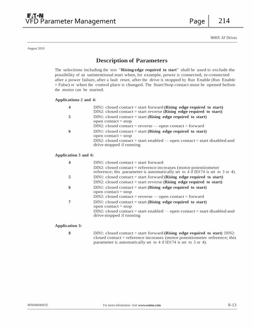
VFD Parameter Management Page 214
9000X AF Drives
August 2010
Description of Parameters
The selections including the text “Rising edge required to start” shall be used to exclude the
possibility of an unintentional start when, for example, power is connected, re-connected
after a power failure, after a fault reset, after the drive is stopped by Run Enable (Run Enable
= False) or when the control place is changed. The Start/Stop contact must be opened before
the motor can be started.
Applications 2 and 4:
4 DIN1: closed contact = start forward (Rising edge required to start) DIN2: closed contact = start reverse (Rising edge required to start)
5 DIN1: closed contact = start (Rising edge required to start) open contact = stop
DIN2: closed contact = reverse — open contact = forward
6 DIN1: closed contact = start (Rising edge required to start) open contact = stop
DIN2: closed contact = start enabled — open contact = start disabled and drive stopped if running
Application 3 and 6:
4 DIN1: closed contact = start forward
DIN2: closed contact = reference increases (motor potentiometer reference; this parameter is automatically set to 4 if ID174 is set to 3 or 4).
5 DIN1: closed contact = start forward (Rising edge required to start)
DIN2: closed contact = start reverse (Rising edge required to start)
6 DIN1: closed contact = start (Rising edge required to start) open contact = stop
DIN2: closed contact = reverse — open contact = forward
7 DIN1: closed contact = start (Rising edge required to start) open contact = stop
DIN2: closed contact = start enabled — open contact = start disabled and drive stopped if running
Application 3:
8 DIN1: closed contact = start forward (Rising edge required to start) DIN2: closed contact = reference increases (motor potentiometer reference; this parameter is automatically set to 4 if ID174 is set to 3 or 4).
MN04004001E For more information visit: www.eaton.com 8-13

VFD Parameter Management Page 215
9000X AF Drives
August 2010
Description of Parameters
301 DIN3 function 12345 (P1.17, P1.2.2)
0 Not used
1 External fault, closing contact = Fault is shown and motor is stopped when the input is active
2 External fault, opening contact = Fault is shown and motor is stopped when the input is not active
3 Run enable: contact open = Motor start disabled and the motor is stopped contact closed = Motor start enabled
Application 1:
4 Run enable: contact open = Motor start enabled contact closed = Motor start disabled and the motor is stopped
Applications 2 to 5:
4 Acc./Dec. time select: contact open = Acceleration/deceleration time 1 selected contact closed = Acceleration/deceleration time 2 selected
5 Closing contact: Force control place to I/O terminal
6 Closing contact: Force control place to keypad
7 Closing contact: Force control place to fieldbus
When the control place is forced to change, the values of Start/Stop, Direction and Reference valid in the respective control place are used (reference according to parameters ID173 and ID174).
Note: The value of ID125 Keypad Control Place does not change. When DIN3 opens the control place is selected according to parameter 3.1.
Applications 2 to 5:
8 Reverse: contact open = Forward contact closed = Reverse
Note: Can be used for reversing if ID300 has a value of 3.
Applications 3 to 5:
9 Jogging speed, contact closed = Jogging speed selected for frequency reference
10 Fault reset, contact closed = Resets all faults
11 Acc./dec. operation prohibited, contact closed = Stops acceleration or deceleration until the contact is opened
12 DC-braking command, contact closed = In Stop mode, the DC-braking operates until the contact is opened, see Figure 8-9.
Applications 3 and 5:
13 Motor potentiometer down, contact closed = Reference decreases until the contact is opened
Application 4:
13 Preset speed
8-14 For more information visit: www.eaton.com MN04004001E

VFD Parameter Management Page 216
9000X AF Drives
August 2010
Description of Parameters
Output
Frequency
ID515
t t
DIN2 DIN2
RUN
STOP
RUN
STOP
a) DIN3 as DC-brake command input and stop-mode = Ramp b) DIN3 as DC-brake command input and stop-mode = Coasting
Figure 8-9: DIN3 as DC-Brake Command Input
a) Stop mode = ramp, b) Stop mode = coasting
302 Reference offset for current input 12 (P1.15, P1.2.3)
0 No offset: 0 – 20 mA
1 Offset: 4 mA (“living zero”) provides supervision of zero level signal. In the Standard Application, the response to reference fault can be programmed with ID700.
303 Reference scaling, minimum value 2346 (P1.2.4, P1.2.16, P1.2.2.6) 304 Reference scaling, maximum value 2346 (P1.2.5, P1.2.17, P1.2.2.7)
Setting value limits: 0 ≤ ID303 ≤ ID304 ≤ ID102. If ID303 = 0 scaling is set off. The minimum and maximum frequencies are used for scaling.
Output
Frequency
Max. Frequency ID102
Output
Frequency
Max. Frequency ID102
ID304 Ref. Scaling Max. Value (1.2.23)
ID303
Min. Frequency ID101
0 10
With Reference Scaling
Analog
Input [V]
Min. Frequency ID101
0 10 Without Reference Scaling
Analog
Input [V]
Figure 8-10: With and Without Reference Scaling
Left: Reference scaling, Right: No scaling used (ID303 = 0)

VFD Parameter Management Page 217
9000X AF Drives
August 2010
Description of Parameters
305 Reference inversion 2 (P1.2.6)
Inverts reference signal: Max. ref. signal = Min. set freq. Min. ref. signal = Max. set freq.
0 No inversion
1 Reference inverted
Output
Frequency
ID304
Max. Freq. ID102
ID303
Min. Freq. ID101
Analog
Input
0 Max.
Figure 8-11: Reference Inversion
306 Reference filter time 2 (P1.2.7)
Filters out disturbances from the incoming analog Vin signal. A long filtering time makes regulation response slower.
%
100%
63%
Unfiltered Signal
Filtered Signal
t [s]
ID306
Figure 8-12: Reference Filtering
307 Analog output function (P1.16, P1.3.2, P1.3.5.2, P1.3.3.2)
This parameter selects the desired function for the analog output signal. See the specific parameters for the values available in each respective application.
8-16 For more information visit: www.eaton.com MN04004001E

VFD Parameter Management Page 218
9000X AF Drives
August 2010
Description of Parameters
308 Analog output filter time 234567 (P1.3.3, P1.3.5.3, P1.3.3.3)
Defines the filtering time for the analog output signal. Setting this parameter value to 0.00 will deactivate filtering.
%
100%
63%
Unfiltered Signal
Filtered Signal
ID308 t [s]
Figure 8-13: Analog Output Filtering
309 Analog output inversion 234567 (P1.3.4, P1.3.5.4, P1.3.3.4)
Inverts the analog output signal:
Maximum output signal = Minimum set value Minimum output signal = Maximum set value
See ID311 in Figure 8-14.
Analog
Output
Current
20 mA
10 mA
ID311 =
200%
ID311 = 50%
ID311 = 100%
Max. Value of Signal
Selected with ID307
0 0.5 1.0
Figure 8-14: Analog Output Invert
310 Analog output minimum 234567 (P1.3.5, P1.3.5.5, P1.3.3.5)
Defines the signal minimum to be either 0 mA or 4 mA (“living zero”). Note the difference in analog output scaling in ID311 (Figure 8-15).
0 Set minimum value to 0 mA
1 Set minimum value to 4 mA

VFD Parameter Management Page 219
9000X AF Drives
August 2010
Description of Parameters
311 Analog output scale 234567 (P1.3.6, P1.3.5.6, P1.3.3.6)
Scaling factor for analog output.
Table 8-7: Analog Output Scaling
Signal Max. value of the signal
Output frequency Max frequency (ID102)
Freq. Reference Max frequency (ID102)
Motor speed Motor nom. speed 1xnmMotor
Output current Motor nom. current 1xInMotor
Motor torque Motor nom. torque 1xTnMotor
Motor power Motor nom. power 1xPnMotor
Motor voltage 100% x VnMotor
DC-link voltage PI-ref. value PI act. value 1 PI act. value 2 PI error value PI output
1000 V 100% x ref. value max. 100% x actual value max. 100% x actual value max. 100% x error value max. 100% x output max.
Analog
Output
Current
20 mA
12 mA
10 mA
ID310 = 1
4 mA
ID311 = 200% ID311 =
100%
ID311 =
50%
Max. Value
of Signal
Selected by ID307
0 mA 0 0.5 1.0
Figure 8-15: Analog Output Scaling
312 Digital output function 23456 (P1.3.7, P1.3.1.2) 313 Relay output 1 function 2345 (P1.3.8, P1.3.1.3) 314 Relay output 2 function 2345 (P1.3.9)
8-18 For more information visit: www.eaton.com MN04004001E

VFD Parameter Management Page 220
9000X AF Drives
August 2010
Description of Parameters
Table 8-8: Output Signals Via DO1 and Output Relays RO1 and RO2
Setting value Signal content
0 = Not used Out of operation
Digital output DO1 sinks current and programmable relay (RO1, RO2) is activated when:
1 = Ready The frequency converter is ready to operate
2 = Run The frequency converter is operating (motor is running)
3 = Fault A fault trip has occurred
4 = Fault inverted A fault trip not occurred
5 = Overheat warning The heat-sink temperature exceeds +70°C
6 = External fault or warning Fault or warning depending on ID701
7 = Reference fault or warning Fault or warning depending on ID700
• if analog reference is 4 – 20 mA and signal is <4 mA
8 = Warning Always if a warning exists
9 = Reversed The reverse command has been selected
10 = Preset speed 1 (Application 2) 10 = Jogging speed (Applications 3456)
The preset speed has been selected with digital input The jogging speed has been selected with digital input
11 = At speed The output frequency has reached the set reference
12 = Motor regulator activated Overvoltage or overcurrent regulator was activated
13 = Output frequency limit supervision The output frequency is outside the set supervision low limit/high limit (ID315 and ID316)
14 = Control from I/O terminals
(Application 2) 14 = Output frequency limit 2 supervision (Applications 3456)
I/O control mode selected (in menu M2)
The output frequency goes outside the set supervision low limit/high limit (ID346 and ID347)
15 = Thermistor fault or warning
(Application 2) 15 = Torque limit supervision (Applications 3456)
The thermistor input of option board indicates overtemperature. Fault or warning depending on ID732. The motor torque is beyond the set supervision low limit/ high limit (ID348 and ID349).
16 = Fieldbus input data
(Application 2) 16 = Reference limit supervision (Applications 3456)
Fieldbus input data (FBFixedControlWord) to DO/RO. Active reference goes beyond the set supervision low limit/
high limit (ID350 and ID351)
17 = External brake control
(Applications 3456) External brake ON/OFF control with programmable delay
(ID352 and ID353)
18 = Control from I/O terminals
(Applications 3456) External control mode (Menu M2; ID125)
19 = Frequency converter temperature limit supervision (Applications 3456)
Frequency converter heatsink temperature goes beyond the set supervision limits (ID354 and ID355).
20 = Unrequested rotation direction
(Applications 345) 20 = Reference inverted (Application 6)
Rotation direction is different from the requested one.
21 = External brake control inverted
(Applications 3456) External brake ON/OFF control (ID352 and ID353); Output active when brake control is OFF
MN04004001E For more information visit: www.eaton.com 8-19

VFD Parameter Management Page 221
21 RO1
22 RO1
23 RO1
21 RO1
22 RO1
23 RO1
21 RO1
22 RO1
23 RO1
9000X AF Drives
August 2010
Description of Parameters
Table 8-8: Output Signals Via DO1 and Output Relays RO1 and RO2, (Continued)
Setting value Signal content
22 = Thermistor fault or warning (Applications 3456)
The thermistor input of option board indicates overtemperature. Fault or warning depending on ID732.
23 = Fieldbus input data (Application 5) 23 = On/Off control (Application 6)
Fieldbus input data (FBFixedControlWord) to DO/RO. Selects the analog input to be monitored. (ID356, ID357, ID358 and ID463)
24 = Fieldbus input data 1 (Application 6)
Fieldbus data (FBFixedControlWord) to DO/RO
25 = Fieldbus input data 2 (Application 6)
Fieldbus data (FBFixedControlWord) to DO/RO
26 = Fieldbus input data 3 (Application 6)
Fieldbus data (FBFixedControlWord) to DO/RO
315 Output frequency limit supervision function
0 No supervision
234567 (P1.3.10, P1.3.4.1, P1.3.2.1)
1 Low limit supervision
2 High limit supervision
3 Brake-on control (Application 6 only, see Page A-1.)
If the output frequency goes under/over the set limit (ID316) this function generates a warning message via the digital output DO1 or via the relay outputs RO1 or RO2 depending on the settings of ID312 to ID314.
316 Output frequency limit
supervision value 234567 (P1.3.11, P1.3.4.2, P1.3.2.2)
Selects the frequency value supervised by ID315. See Figure 8-16.
f [Hz] ID315 = 2
ID316
t
Example:
Figure 8-16: Output Frequency Supervision
8-20 For more information visit: www.eaton.com MN04004001E
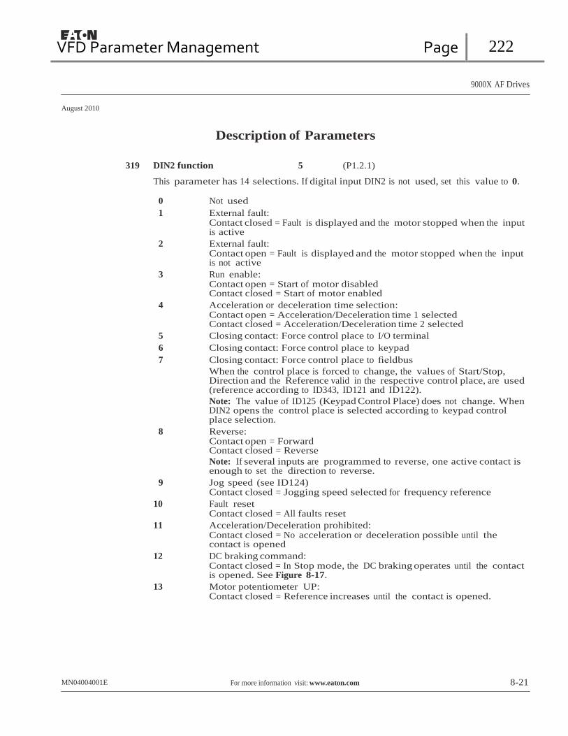
VFD Parameter Management Page 222
9000X AF Drives
August 2010
Description of Parameters
319 DIN2 function 5 (P1.2.1)
This parameter has 14 selections. If digital input DIN2 is not used, set this value to 0.
0 Not used
1 External fault: Contact closed = Fault is displayed and the motor stopped when the input is active
2 External fault: Contact open = Fault is displayed and the motor stopped when the input is not active
3 Run enable: Contact open = Start of motor disabled Contact closed = Start of motor enabled
4 Acceleration or deceleration time selection: Contact open = Acceleration/Deceleration time 1 selected Contact closed = Acceleration/Deceleration time 2 selected
5 Closing contact: Force control place to I/O terminal
6 Closing contact: Force control place to keypad
7 Closing contact: Force control place to fieldbus
When the control place is forced to change, the values of Start/Stop, Direction and the Reference valid in the respective control place, are used (reference according to ID343, ID121 and ID122).
Note: The value of ID125 (Keypad Control Place) does not change. When DIN2 opens the control place is selected according to keypad control place selection.
8 Reverse: Contact open = Forward Contact closed = Reverse
Note: If several inputs are programmed to reverse, one active contact is enough to set the direction to reverse.
9 Jog speed (see ID124) Contact closed = Jogging speed selected for frequency reference
10 Fault reset Contact closed = All faults reset
11 Acceleration/Deceleration prohibited: Contact closed = No acceleration or deceleration possible until the contact is opened
12 DC braking command: Contact closed = In Stop mode, the DC braking operates until the contact is opened. See Figure 8-17.
13 Motor potentiometer UP: Contact closed = Reference increases until the contact is opened.
MN04004001E For more information visit: www.eaton.com 8-21
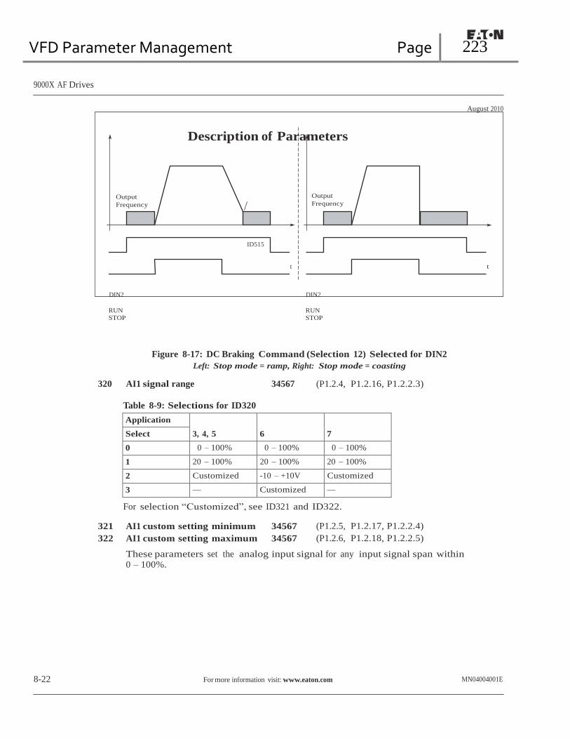
VFD Parameter Management Page 223
9000X AF Drives
August 2010
Description of Parameters
Output
Frequency
Output
Frequency
ID515
t t
DIN2 DIN2
RUN
STOP
RUN
STOP
Figure 8-17: DC Braking Command (Selection 12) Selected for DIN2
Left: Stop mode = ramp, Right: Stop mode = coasting
320 AI1 signal range 34567 (P1.2.4, P1.2.16, P1.2.2.3)
Table 8-9: Selections for ID320
Application
3, 4, 5
6
7 Select
0 0 – 100% 0 – 100% 0 – 100%
1 20 – 100% 20 – 100% 20 – 100%
2 Customized -10 – +10V Customized
3 — Customized —
For selection “Customized”, see ID321 and ID322.
321 AI1 custom setting minimum 34567 (P1.2.5, P1.2.17, P1.2.2.4) 322 AI1 custom setting maximum 34567 (P1.2.6, P1.2.18, P1.2.2.5)
These parameters set the analog input signal for any input signal span within 0 – 100%.
8-22 For more information visit: www.eaton.com MN04004001E

VFD Parameter Management Page 224
9000X AF Drives
August 2010
Description of Parameters
323 AI1 signal inversion 3457 (P1.2.7, P1.2.19, P1.2.2.6)
If this parameter = 0 no inversion of analog Vin signal takes place.
Note: In Application 3, AI1 is place B frequency reference if parameter
ID131 = 0 (default).
ID303
Output Frequency
ID320 = 0 AI1 = 0 – 100%
ID304 ID320 = 1 AI1 = Custom
AI1 (Term. 2)
0 ID321 ID322 100%
Figure 8-18: AI1 No Signal Inversion
If this parameter = 1 inversion of analog signal takes place. max. AI1 signal = minimum set speed min. AI1 signal = maximum set speed
ID303
Output Frequency
ID320 = 0 AI1 = 0 – 100%
ID304
ID320 = 1 AI1 = Custom
AI1 (Term. 2)
0 ID321
ID322
100%
Figure 8-19: AI1 Signal Inversion
MN04004001E For more information visit: www.eaton.com 8-23

VFD Parameter Management Page 225
9000X AF Drives
August 2010
Description of Parameters
324 AI1 signal filter time 34567 (P1.2.8, P1.2.20, P1.2.2.2)
When this parameter is given a value greater than 0, the function that filters out disturbances from the incoming analog signal is activated.
A long filtering time makes the regulation response slower. See Figure 8-20.
%
100%
63%
Unfiltered Signal
Filtered Signal
ID308 t [s]
Figure 8-20: AI1 Signal Filtering
325 Analog input AI2 signal range 34567 (P1.2.10, P1.2.22, P1.2.3.3)
Table 8-10: Selections for Parameter ID325
Application 3, 4
5
6
7 Select
0 0 – 20 mA 0 – 20 mA 0 – 100% 0 – 100% 1 4 – 20 mA 4 mA/
20 – 100% 20 – 100% 20 – 100%
2 Customized Customized -10 – +10V Customized 3 — — Customized —
ID304
Output
Frequency
ID325 = Custom
ID325 = 0
AI2 = 0 – 100%
ID303
0
ID326
ID325 = 1
AI2 = 20 – 100%
4 mA
ID327
AI2
(Term. 3,4)
20 mA
Figure 8-21: Analog Input AI2 Scaling
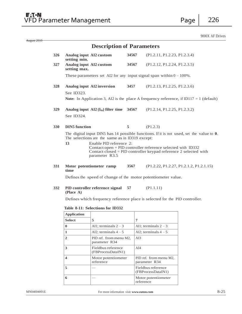
VFD Parameter Management Page 226
9000X AF Drives
August 2010
Description of Parameters
326 Analog input AI2 custom setting min.
327 Analog input AI2 custom setting max.
34567 (P1.2.11, P1.2.23, P1.2.3.4)
34567 (P1.2.12, P1.2.24, P1.2.3.5)
These parameters set AI2 for any input signal span within 0 – 100%.
328 Analog input AI2 inversion 3457 (P1.2.13, P1.2.25, P1.2.3.6)
See ID323.
Note: In Application 3, AI2 is the place A frequency reference, if ID117 = 1 (default)
329 Analog input AI2 (Iin) filter time 34567 (P1.2.14, P1.2.25, P1.2.3.2)
See ID324.
330 DIN5 function 5 (P1.2.3)
The digital input DIN5 has 14 possible functions. If it is not used, set the value to 0. The selections are the same as in ID319 except:
13 Enable PID reference 2: Contact open = PID controller reference selected with ID332 Contact closed = PID controller keypad reference 2 selected with parameter R3.5
331 Motor potentiometer ramp
time 3567 (P1.2.22, P1.2.27, P1.2.1.2, P1.2.1.15)
Defines the speed of change of the motor potentiometer value.
332 PID controller reference signal
(Place A) 57 (P1.1.11)
Defines which frequency reference place is selected for the PID controller.
Table 8-11: Selections for ID332
Application
5
7 Select
0 AI1; terminals 2 – 3 AI1; terminals 2 – 3
1 AI2; terminals 4 – 5 AI2; terminals 4 – 5
2 PID ref. from menu M2, parameter R34
AI3
3 Fieldbus reference (FBProcessDataIN1)
AI4
4 Motor potentiometer reference
PID ref. from menu M2, parameter R34
5 — Fieldbus reference
(FBProcessDataIN1)
6 — Motor potentiometer reference
MN04004001E For more information visit: www.eaton.com 8-25
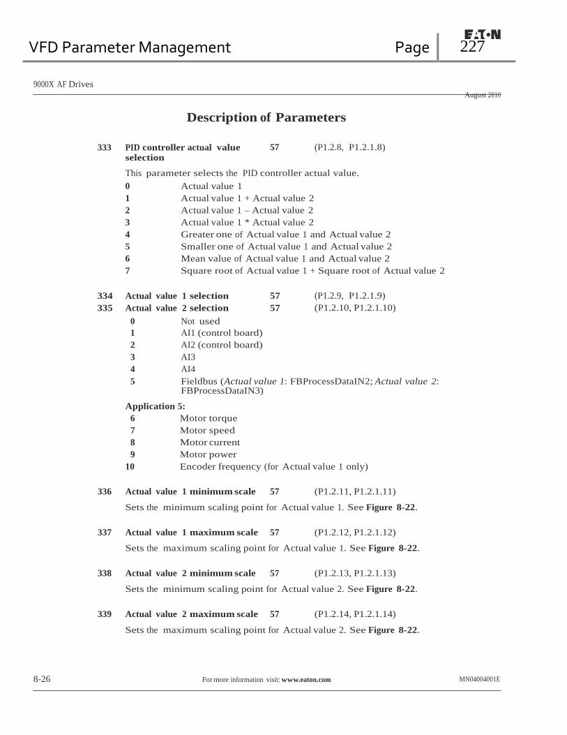
VFD Parameter Management Page 227
9000X AF Drives
August 2010
Description of Parameters
333 PID controller actual value selection
57 (P1.2.8, P1.2.1.8)
This parameter selects the PID controller actual value.
0 Actual value 1
1 Actual value 1 + Actual value 2
2 Actual value 1 – Actual value 2
3 Actual value 1 * Actual value 2
4 Greater one of Actual value 1 and Actual value 2
5 Smaller one of Actual value 1 and Actual value 2
6 Mean value of Actual value 1 and Actual value 2
7 Square root of Actual value 1 + Square root of Actual value 2
334 Actual value 1 selection 57 (P1.2.9, P1.2.1.9) 335 Actual value 2 selection 57 (P1.2.10, P1.2.1.10)
0 Not used
1 AI1 (control board)
2 AI2 (control board)
3 AI3
4 AI4
5 Fieldbus (Actual value 1: FBProcessDataIN2; Actual value 2: FBProcessDataIN3)
Application 5:
6 Motor torque
7 Motor speed
8 Motor current
9 Motor power
10 Encoder frequency (for Actual value 1 only)
336 Actual value 1 minimum scale 57 (P1.2.11, P1.2.1.11)
Sets the minimum scaling point for Actual value 1. See Figure 8-22.
337 Actual value 1 maximum scale 57 (P1.2.12, P1.2.1.12)
Sets the maximum scaling point for Actual value 1. See Figure 8-22.
338 Actual value 2 minimum scale 57 (P1.2.13, P1.2.1.13)
Sets the minimum scaling point for Actual value 2. See Figure 8-22.
339 Actual value 2 maximum scale 57 (P1.2.14, P1.2.1.14)
Sets the maximum scaling point for Actual value 2. See Figure 8-22.
8-26 For more information visit: www.eaton.com MN04004001E

VFD Parameter Management Page 228
9000X AF Drives
August 2010
Description of Parameters
Scaled
Input Signal [%]
100 100
Scaled
Input Signal [%]
ID336 = 30%
ID337 = 80%
76.5
(15.3 mA)
ID338 = -30%
ID339 = 140%
30 80 0
Analog
100 Input [%]
17.7
(3.5 mA)
-30 0
100
Analog
140 Input [%]
0 3.3
0 6.0
4 8.8
8.0
16.0
16.8
10.0V 0
20.0 mA 0
20.0 mA 4
10.0V
20.0 mA
20.0 mA
Figure 8-22: Examples of Actual Value Signal Scaling
340 PID error value inversion 57 (P1.2.32, P1.2.1.5)
This parameter allows you to invert the error value of the PID controller (and thus the operation of the PID controller).
0 No inversion
1 Inverted
341 PID reference rise time 57 (P1.2.33, P1.2.1.6)
Defines the time during which the PID controller reference rises from 0% to 100%.
342 PID reference fall time 57 (P1.2.34, P1.2.1.7)
Defines the time during which the PID controller reference falls from 100% to 0%.
344 Reference scaling minimum value, place B
57 (P1.2.35, P1.2.1.18)
MN04004001E For more information visit: www.eaton.com 8-27

VFD Parameter Management Page 229
9000X AF Drives
August 2010
Description of Parameters
345 Reference scaling maximum value, place B
57 (P1.2.36, P1.2.1.19)
You can choose a scaling range for the frequency reference from control place B between the Minimum and Maximum frequency.
If no scaling is desired set the parameter value to 0.0.
In Figure 8-23, input AI1 with signal range 0 – 100% is selected for Place B reference.
Output
Frequency
Output
Frequency
Max. Frequency ID102 Max. Frequency ID102
ID345
Min. Frequency ID101
0
Analog
Input [V]
10
ID344 Min. Frequency ID101
0
Analog
Input [V] 10
Figure 8-23: Control Place B with and without Reference Scaling
Left: ID344 = 0 (No reference scaling), Right: reference scaling
346 Output freq. limit 2 supervision function
0 No supervision
34567 (P1.3.12, P1.3.4.3, P1.3.2.3)
1 Low limit supervision
2 High limit supervision
3 Brake-on control (Application 6 only, see Page A-1.)
4 Brake-on/off control (Application 6 only, see Page A-1.)
If the output frequency goes under/over the set limit (ID347) this function generates a warning message via the digital output DO1 or relay outputs RO1 or RO2 depending on:
1) the settings of ID312 to ID314 (Applications 3, 4, 5) or …
2) to which output the supervision signals (ID447 and ID448) are connected (Applications 6 and 7).
347 Output frequency limit 2
supervision value 34567 (P1.3.13, P1.3.4.4, P1.3.2.4)
Selects the frequency value supervised by ID346. See Figure 8-16.
8-28 For more information visit: www.eaton.com MN04004001E
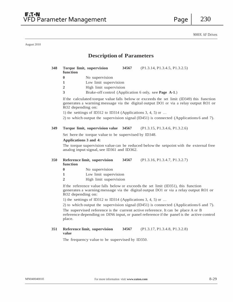
VFD Parameter Management Page 230
9000X AF Drives
August 2010
Description of Parameters
348 Torque limit, supervision function
0 No supervision
34567 (P1.3.14, P1.3.4.5, P1.3.2.5)
1 Low limit supervision
2 High limit supervision
3 Brake-off control (Application 6 only, see Page A-1.)
If the calculated torque value falls below or exceeds the set limit (ID349) this function generates a warning message via the digital output DO1 or via a relay output RO1 or RO2 depending on:
1) the settings of ID312 to ID314 (Applications 3, 4, 5) or …
2) to which output the supervision signal (ID451) is connected (Applications 6 and 7).
349 Torque limit, supervision value 34567 (P1.3.15, P1.3.4.6, P1.3.2.6)
Set here the torque value to be supervised by ID348.
Applications 3 and 4:
The torque supervision value can be reduced below the setpoint with the external free analog input signal, see ID361 and ID362.
350 Reference limit, supervision
function
0 No supervision
34567 (P1.3.16, P1.3.4.7, P1.3.2.7)
1 Low limit supervision
2 High limit supervision
If the reference value falls below or exceeds the set limit (ID351), this function generates a warning message via the digital output DO1 or via a relay output RO1 or RO2 depending on:
1) the settings of ID312 to ID314 (Applications 3, 4, 5) or …
2) to which output the supervision signal (ID451) is connected (Applications 6 and 7).
The supervised reference is the current active reference. It can be place A or B
reference depending on DIN6 input, or panel reference if the panel is the active control place.
351 Reference limit, supervision
value 34567 (P1.3.17, P1.3.4.8, P1.3.2.8)
The frequency value to be supervised by ID350.
MN04004001E For more information visit: www.eaton.com 8-29
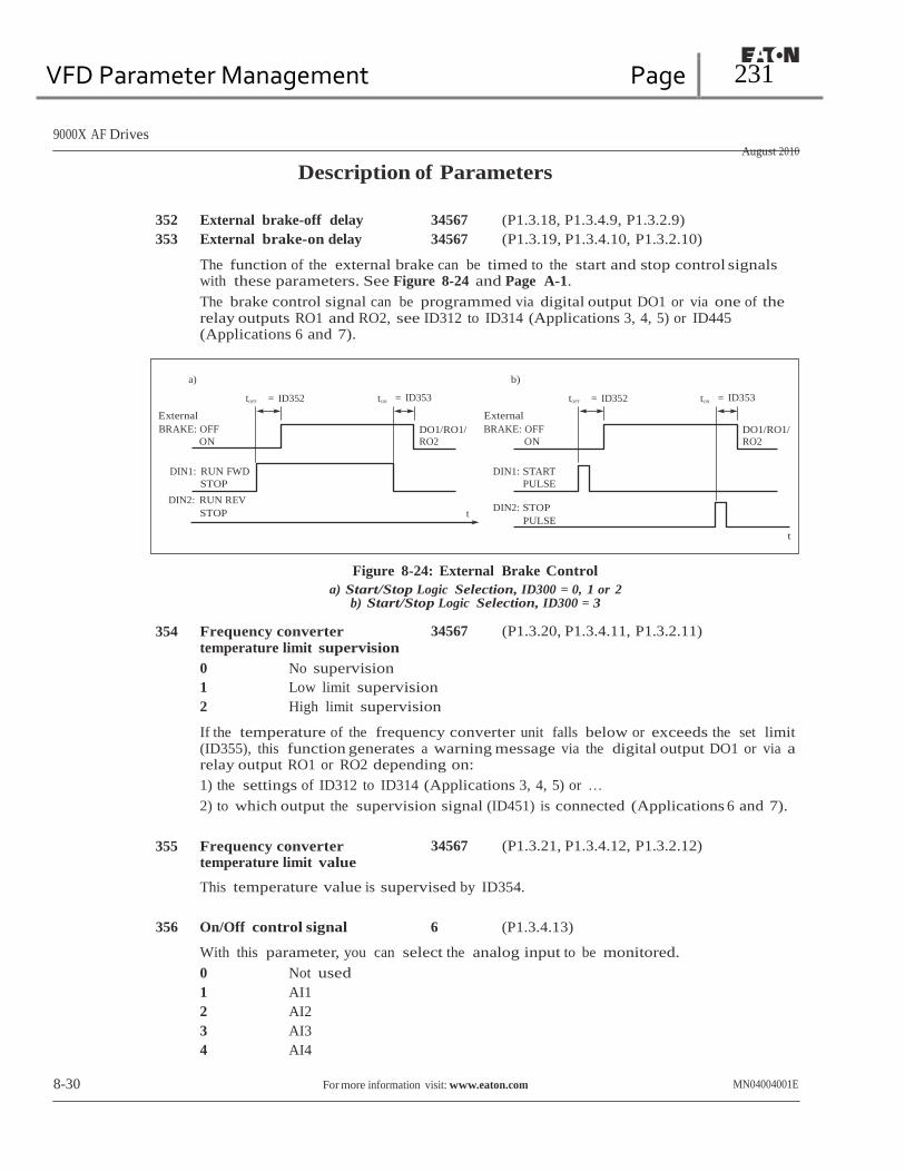
VFD Parameter Management Page 231
9000X AF Drives
August 2010
Description of Parameters
352 External brake-off delay 34567 (P1.3.18, P1.3.4.9, P1.3.2.9)
353 External brake-on delay 34567 (P1.3.19, P1.3.4.10, P1.3.2.10)
The function of the external brake can be timed to the start and stop control signals with these parameters. See Figure 8-24 and Page A-1.
The brake control signal can be programmed via digital output DO1 or via one of the relay outputs RO1 and RO2, see ID312 to ID314 (Applications 3, 4, 5) or ID445 (Applications 6 and 7).
a) b)
tOFF = ID352 tON = ID353 tOFF = ID352 tON
= ID353
External
BRAKE: OFF
ON
DO1/RO1/
RO2
External
BRAKE: OFF
ON
DO1/RO1/
RO2
DIN1: RUN FWD
STOP
DIN2: RUN REV
STOP
DIN1: START
PULSE
t DIN2: STOP
PULSE
t
Figure 8-24: External Brake Control
a) Start/Stop Logic Selection, ID300 = 0, 1 or 2 b) Start/Stop Logic Selection, ID300 = 3
354 Frequency converter temperature limit supervision
0 No supervision
34567 (P1.3.20, P1.3.4.11, P1.3.2.11)
1 Low limit supervision
2 High limit supervision
If the temperature of the frequency converter unit falls below or exceeds the set limit (ID355), this function generates a warning message via the digital output DO1 or via a relay output RO1 or RO2 depending on:
1) the settings of ID312 to ID314 (Applications 3, 4, 5) or …
2) to which output the supervision signal (ID451) is connected (Applications 6 and 7).
355 Frequency converter
temperature limit value 34567 (P1.3.21, P1.3.4.12, P1.3.2.12)
This temperature value is supervised by ID354.
356 On/Off control signal 6 (P1.3.4.13)
With this parameter, you can select the analog input to be monitored.
0 Not used
1 AI1
2 AI2
3 AI3
4 AI4
8-30 For more information visit: www.eaton.com MN04004001E

VFD Parameter Management Page 232
9000X AF Drives
August 2010
Description of Parameters
357 On/Off control low limit 6 (P1.3.4.14)
358 On/Off control high limit 6 (P1.3.4.15)
These parameters set the low and high limits of the signal selected with ID356. See Figure 8-25.
Analog Input (Selected with ID356)
ID358
ID357
Time
RO1 1
0
In this example the programming of ID463 = B.1.
Figure 8-25: An Example of On/Off-Control
359 PID controller minimum limit 5 (P1.2.30) 360 PID controller maximum limit 5 (P1.2.31)
With these parameters, you can set the minimum and maximum limits for the PID controller output.
Limit setting: -1000.0% (of fmax) < ID359 < ID360 < 1000.0% (of fmax).
These limits are of importance for example when you define the gain, I-time and D-time for the PID controller.
361 Free analog input, signal
selection 34 (P1.2.20, P1.2.17)
Selection of input signal for the free analog input (an input not used for a reference signal):
0 Not in use
1 Voltage signal Vin
2 Current signal Iin
MN04004001E For more information visit: www.eaton.com 8-31

VFD Parameter Management Page 233
9000X AF Drives
August 2010
Description of Parameters
362 Free analog input, function 34 (P1.2.21, P1.2.18)
This parameter is used for selecting a function for the free analog input signal:
0 Function is not in use
1 Reduces motor current limit (ID107)
This signal will adjust the maximum motor current between 0 and maximum limit set with ID107. See Figure 8-26.
Torque Limit
100%
ID107
0 V Signal Range
10 V
Analog
Input
0 mA
4 mA
Custom
20 mA
20 mA
Custom
Figure 8-26: Scaling of Max. Motor Current
2 Reduces DC braking current
DC braking current can be reduced with the free analog input signal between current 0.4 x IH and the current set with ID507. See Figure 8-27.
100%
ID507
DC-Braking
Current
0.15xIL
0
Signal Range
Free Analog
Input
Figure 8-27: Reduction of DC Braking Current
8-32 For more information visit: www.eaton.com MN04004001E

VFD Parameter Management Page 234
9000X AF Drives
August 2010
Description of Parameters
3 Reduces acceleration and deceleration times
Acceleration and deceleration times can be reduced with the free analog input signal according to the following formulas:
Reduced time = set acc./decel. time (ID103, ID104; ID502, ID503) divided by the factor R in Figure 8-28.
Factor R
10
2 Free
1
0 Signal Range
Analog
Input
Figure 8-28: Reduction of Acceleration and Deceleration Times
4 Reduces torque supervision limit
Set supervision limit can be reduced with the free analog input signal between 0 and set supervision limit (ID349), see Figure 8-29.
100%
Par. ID349
Torque
Limit
0 Signal Range
Free
Analog
Input
Figure 8-29: Reduction of Torque Supervision Limit
MN04004001E For more information visit: www.eaton.com 8-33

VFD Parameter Management Page 235
9000X AF Drives
August 2010
Description of Parameters
363 Start/Stop logic selection, place B
3 (P1.2.15)
0 DIN4: closed contact = start forward DIN5: closed contact = start reverse
FWD Output
Frequency Stop Function
(ID506) = Coasting
t
REV
DIN4
DIN5
1 2 3
Figure 8-30: Place B Start Forward/Start Reverse
The first selected direction has the highest priority.
When the DIN4 contact opens the direction of rotation starts to change.
If Start forward (DIN4) and Start reverse (DIN5) signals are active simultaneously, the Start forward signal (DIN4) has priority.
1 DIN4: closed contact = start — open contact = stop DIN5: closed contact = reverse — open contact = forward
See Figure 8-31.
FWD Output
Frequency
Stop Function
(ID506) = Coasting
t
REV
DIN4
DIN5
Figure 8-31: Place B Start, Stop, Reverse
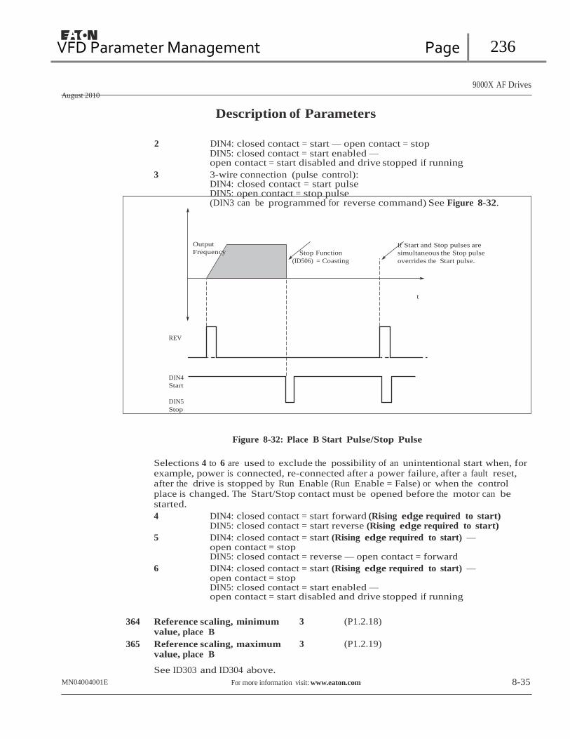
VFD Parameter Management Page 236
9000X AF Drives
August 2010
Description of Parameters
2 DIN4: closed contact = start — open contact = stop DIN5: closed contact = start enabled — open contact = start disabled and drive stopped if running
3 3-wire connection (pulse control): DIN4: closed contact = start pulse DIN5: open contact = stop pulse (DIN3 can be programmed for reverse command) See Figure 8-32.
Output
Frequency Stop Function
(ID506) = Coasting
If Start and Stop pulses are
simultaneous the Stop pulse
overrides the Start pulse.
t
REV
DIN4
Start
DIN5
Stop
Figure 8-32: Place B Start Pulse/Stop Pulse
Selections 4 to 6 are used to exclude the possibility of an unintentional start when, for example, power is connected, re-connected after a power failure, after a fault reset, after the drive is stopped by Run Enable (Run Enable = False) or when the control place is changed. The Start/Stop contact must be opened before the motor can be started.
4 DIN4: closed contact = start forward (Rising edge required to start) DIN5: closed contact = start reverse (Rising edge required to start)
5 DIN4: closed contact = start (Rising edge required to start) — open contact = stop DIN5: closed contact = reverse — open contact = forward
6 DIN4: closed contact = start (Rising edge required to start) — open contact = stop DIN5: closed contact = start enabled — open contact = start disabled and drive stopped if running
364 Reference scaling, minimum
value, place B
365 Reference scaling, maximum value, place B
See ID303 and ID304 above.
3 (P1.2.18)
3 (P1.2.19)
MN04004001E For more information visit: www.eaton.com 8-35

VFD Parameter Management Page 237
9000X AF Drives
August 2010
Description of Parameters
367 Motor potentiometer memory reset (Frequency reference)
0 No reset
3567 (P1.2.23, P1.2.28, P1.2.1.3, P1.2.1.16)
1 Memory reset in stop and power down
2 Memory reset in power down
370 Motor potentiometer memory
reset (PID reference)
0 No reset
57 (P1.2.29, P1.2.1.17)
1 Memory reset in stop and power down
2 Memory reset in power down
371 PID reference 2 (Place A
additional reference) 7 (P1.2.1.4)
If the PID reference 2 enable input function ID330 = TRUE, this parameter defines which reference place is selected as PID controller reference.
0 AI1 reference (terminals 2 and 3, e.g. potentiometer)
1 AI2 reference (terminals 5 and 6, e.g. transducer)
2 AI3 reference
3 AI4 reference
4 PID reference 1 from keypad
5 Reference from Fieldbus (FBProcessDataIN3)
6 Motor potentiometer
7 PID reference 2 from keypad
If value 6 is selected for this parameter, the functions Motor potentiometer DOWN and Motor potentiometer UP must be connected to digital inputs (ID417 and ID418).
372 Supervised analog input 7 (P1.3.2.13)
0 Analog reference from AI1 (terminals 2 and 3, e.g. potentiometer)
1 Analog reference from AI2 (terminals 4 and 5, e.g. transducer)
373 Analog input limit supervision 7 (P1.3.2.14)
If the value of the selected analog input goes under/over the set limit (ID374), this function generates a warning message through the digital output or the relay outputs depending on to which output the supervision function (ID463) is connected.
0 No supervision
1 Low limit supervision
2 High limit supervision
8-36 For more information visit: www.eaton.com MN04004001E

VFD Parameter Management Page 238
9000X AF Drives
August 2010
Description of Parameters
374 Analog input supervised value 7 (P1.3.2.15)
The value of the selected analog input to be supervised by ID373.
375 Analog output offset 67 (P1.3.5.7, P1.3.3.7)
Add -100.0 to 100.0% to the analog output.
376 PID sum point reference (Place
A direct reference) 5 (P1.2.4)
Defines which reference source is added to PID controller output if PID controller is used.
0 No additional reference (Direct PID output value)
1 PID output + AI1 reference from terminals 2 and 3 (e.g. potentiometer)
2 PID output + AI2 reference from terminals 4 and 5 (e.g. transducer)
3 PID output + PID keypad reference
4 PID output + Fieldbus reference (FBSpeedReference)
5 PID output + Motor potentiometer reference
If value 5 is selected for this parameter, the values of ID319 and ID301 are automatically set to 13. See Figure 8-33.
Hz
30.00
PID Max Limit
PID Min Limit
20.00
t
Figure 8-33: PID Sum Point Reference
Note: The maximum and minimum limits illustrated in the picture limit only the PID output, no other outputs are affected.
MN04004001E For more information visit: www.eaton.com 8-37
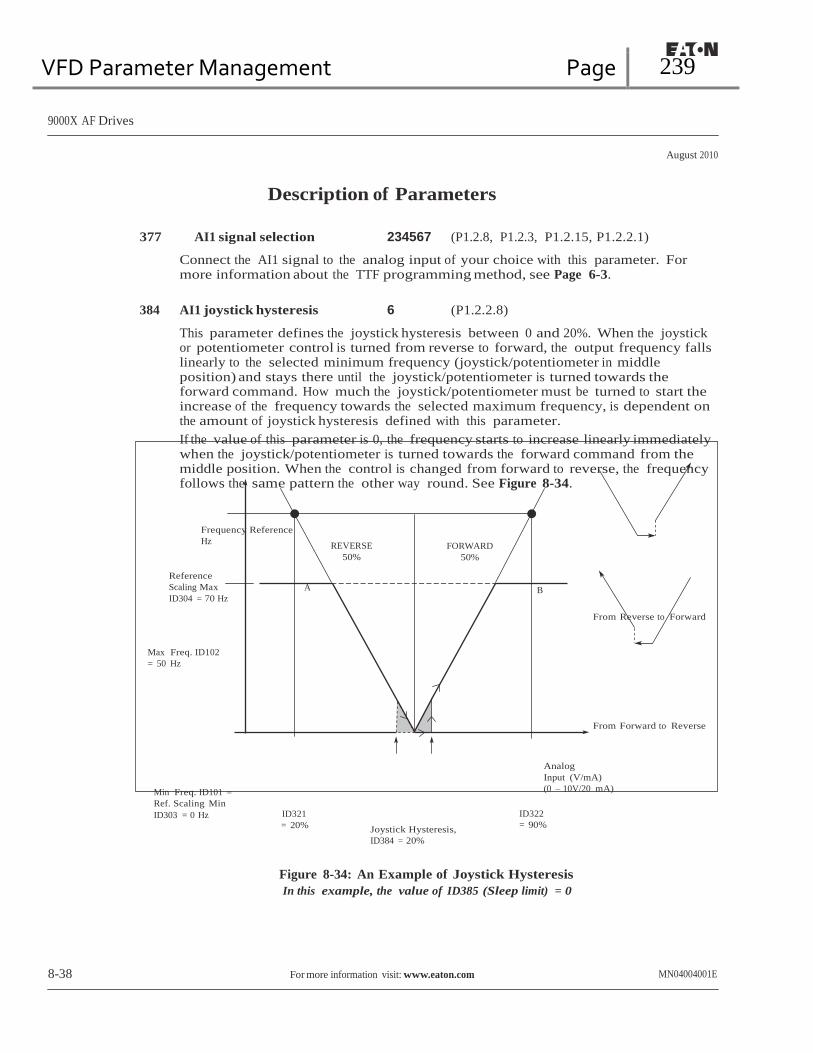
VFD Parameter Management Page 239
9000X AF Drives
August 2010
Description of Parameters
377 AI1 signal selection 234567 (P1.2.8, P1.2.3, P1.2.15, P1.2.2.1)
Connect the AI1 signal to the analog input of your choice with this parameter. For more information about the TTF programming method, see Page 6-3.
384 AI1 joystick hysteresis 6 (P1.2.2.8)
This parameter defines the joystick hysteresis between 0 and 20%. When the joystick or potentiometer control is turned from reverse to forward, the output frequency falls linearly to the selected minimum frequency (joystick/potentiometer in middle position) and stays there until the joystick/potentiometer is turned towards the forward command. How much the joystick/potentiometer must be turned to start the increase of the frequency towards the selected maximum frequency, is dependent on the amount of joystick hysteresis defined with this parameter.
If the value of this parameter is 0, the frequency starts to increase linearly immediately when the joystick/potentiometer is turned towards the forward command from the middle position. When the control is changed from forward to reverse, the frequency follows the same pattern the other way round. See Figure 8-34.
Frequency Reference
Hz REVERSE
50%
FORWARD
50%
Reference
Scaling Max
ID304 = 70 Hz
Max Freq. ID102
= 50 Hz
A B
From Reverse to Forward
From Forward to Reverse
Min Freq. ID101 =
Ref. Scaling Min
ID303 = 0 Hz ID321 = 20%
Joystick Hysteresis,
ID384 = 20%
Analog
Input (V/mA)
(0 – 10V/20 mA)
ID322
= 90%
Figure 8-34: An Example of Joystick Hysteresis
In this example, the value of ID385 (Sleep limit) = 0
8-38 For more information visit: www.eaton.com MN04004001E

VFD Parameter Management Page 240
9000X AF Drives
August 2010
Description of Parameters
385 AI1 sleep limit 6 (P1.2.2.9)
The frequency converter is automatically stopped if the AI signal level falls below the Sleep limit defined with this parameter. See Figure 8-35.
Frequency Reference
Hz
Reference
REVERSE
50%
FORWARD
50%
Scaling Max
ID304 = 70 Hz
Max Freq. ID102
= 50 Hz
A B
From Reverse to Forward
START STOP
STOP
START
From Forward to Reverse
Min Freq. ID101 =
Ref. Scaling Min
ID303 = 0 Hz ID321 = 20%
Sleep Limit
ID385 = 7%
Joystick Hysteresis,
ID384 = 20%
ID322
= 90%
Analog
Input (V/mA)
(0 – 10V/20 mA)
Figure 8-35: Example of Sleep Limit Function
MN04004001E For more information visit: www.eaton.com 8-39
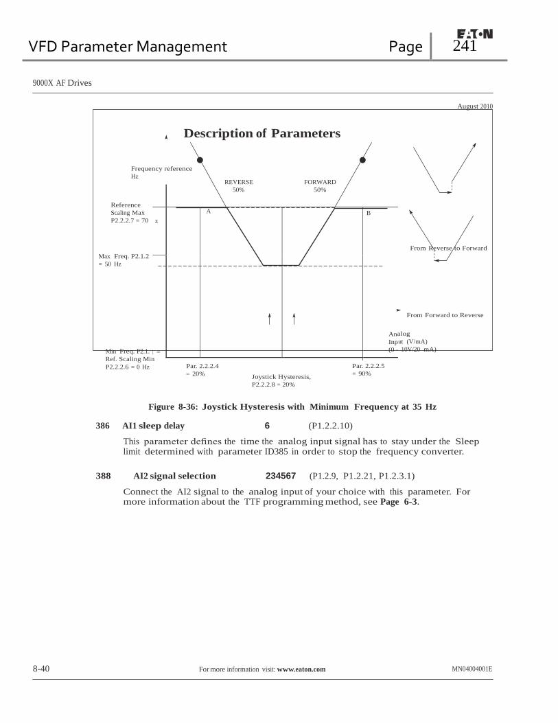
VFD Parameter Management Page 241
50% 50%
z
A B
An
Inp
(0 –
1 =
9000X AF Drives
August 2010
Description of Parameters
Frequency reference
Hz
Reference
Scaling Max
P2.2.2.7 = 70
REVERSE
FORWARD
Max Freq. P2.1.2
= 50 Hz
From Reverse to Forward
From Forward to Reverse
Min Freq. P2.1.
Ref. Scaling Min
P2.2.2.6 = 0 Hz Par. 2.2.2.4 = 20%
Joystick Hysteresis,
P2.2.2.8 = 20%
Par. 2.2.2.5
= 90%
alog
ut (V/mA)
10V/20 mA)
Figure 8-36: Joystick Hysteresis with Minimum Frequency at 35 Hz
386 AI1 sleep delay 6 (P1.2.2.10)
This parameter defines the time the analog input signal has to stay under the Sleep limit determined with parameter ID385 in order to stop the frequency converter.
388 AI2 signal selection 234567 (P1.2.9, P1.2.21, P1.2.3.1)
Connect the AI2 signal to the analog input of your choice with this parameter. For more information about the TTF programming method, see Page 6-3.
8-40 For more information visit: www.eaton.com MN04004001E
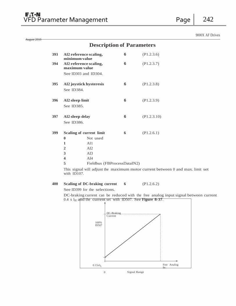
VFD Parameter Management Page 242
9000X AF Drives
August 2010
Description of Parameters
393 AI2 reference scaling, minimum value
394 AI2 reference scaling, maximum value
See ID303 and ID304.
6 (P1.2.3.6)
6 (P1.2.3.7)
395 AI2 joystick hysteresis 6 (P1.2.3.8)
See ID384.
396 AI2 sleep limit 6 (P1.2.3.9)
See ID385.
397 AI2 sleep delay 6 (P1.2.3.10)
See ID386.
399 Scaling of current limit 6 (P1.2.6.1)
0 Not used
1 AI1
2 AI2
3 AI3
4 AI4
5 Fieldbus (FBProcessDataIN2)
This signal will adjust the maximum motor current between 0 and max. limit set with ID107.
400 Scaling of DC-braking current 6 (P1.2.6.2)
See ID399 for the selections.
DC-braking current can be reduced with the free analog input signal between current 0.4 x IH and the current set with ID507. See Figure 8-37.
DC-Braking Current
100% ID507
0.15xIL
0
Signal Range
Free Analog In

VFD Parameter Management Page 243
9000X AF Drives
August 2010
Description of Parameters 401 Reducing of acceleration and
deceleration times
See ID399.
6 (P1.2.6.3)
Acceleration and deceleration times can be reduced with the free analog input signal according to the following formulas:
Reduced time = set acc./deceler. time (ID103, ID104; ID502, ID503) divided by the factor R from Figure 8-38.
Factor R
10
2 Free
Analog 1
Input
Signal Range
Figure 8-38: Reducing Acceleration and Deceleration Times
402 Reducing of torque supervision limit 6 (P1.2.6.4)
See ID399.
The set torque supervision limit can be reduced with the free analog input signal between 0 and the set supervision limit, ID349. See Figure 8-39.
Torque Limit
100%
ID349
0 Signal Range
Free Analog Input
Figure 8-39: Reducing Torque Supervision Limit
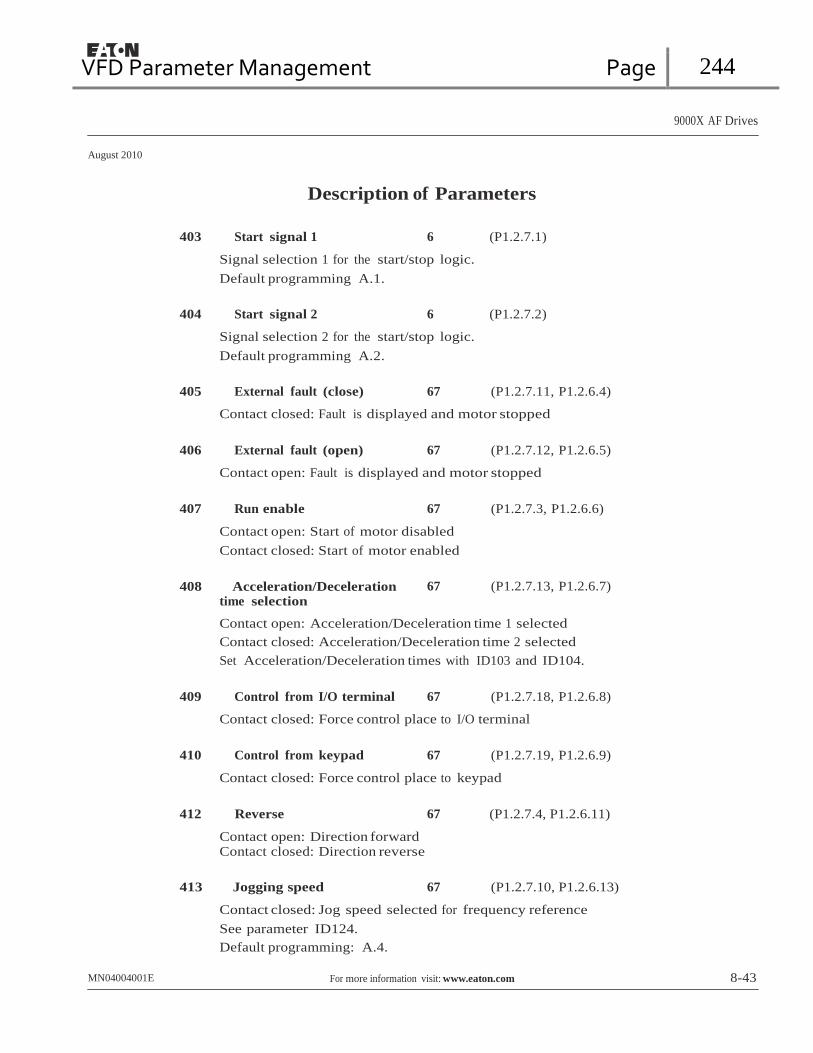
VFD Parameter Management Page 244
9000X AF Drives
August 2010
Description of Parameters
403 Start signal 1 6 (P1.2.7.1)
Signal selection 1 for the start/stop logic.
Default programming A.1.
404 Start signal 2 6 (P1.2.7.2)
Signal selection 2 for the start/stop logic.
Default programming A.2.
405 External fault (close) 67 (P1.2.7.11, P1.2.6.4)
Contact closed: Fault is displayed and motor stopped
406 External fault (open) 67 (P1.2.7.12, P1.2.6.5)
Contact open: Fault is displayed and motor stopped
407 Run enable 67 (P1.2.7.3, P1.2.6.6)
Contact open: Start of motor disabled
Contact closed: Start of motor enabled
408 Acceleration/Deceleration
time selection 67 (P1.2.7.13, P1.2.6.7)
Contact open: Acceleration/Deceleration time 1 selected
Contact closed: Acceleration/Deceleration time 2 selected
Set Acceleration/Deceleration times with ID103 and ID104.
409 Control from I/O terminal 67 (P1.2.7.18, P1.2.6.8)
Contact closed: Force control place to I/O terminal
410 Control from keypad 67 (P1.2.7.19, P1.2.6.9)
Contact closed: Force control place to keypad
412 Reverse 67 (P1.2.7.4, P1.2.6.11)
Contact open: Direction forward Contact closed: Direction reverse
413 Jogging speed 67 (P1.2.7.10, P1.2.6.13)
Contact closed: Jog speed selected for frequency reference
See parameter ID124.
Default programming: A.4.
MN04004001E For more information visit: www.eaton.com 8-43

VFD Parameter Management Page 245
9000X AF Drives
August 2010
Description of Parameters
414 Fault reset 67 (P1.2.7.10, P1.2.6.13)
Contact closed: All faults are reset.
415 Acceleration/Deceleration
prohibited 67 (P1.2.7.14, P1.2.6.14)
Contact closed: No acceleration or deceleration possible until the contact is opened.
416 DC-braking 67 (P1.2.7.15, P1.2.6.15)
Contact closed: In STOP mode, the DC braking operates until the contact is opened.
417 Motor potentiometer DOWN 67 (P1.2.7.8, P1.2.6.16)
Contact closed: Motor potentiometer reference DECREASES until the contact is opened.
418 Motor potentiometer UP 67 (P1.2.7.9, P1.2.6.17)
Contact closed: Motor potentiometer reference INCREASES until the contact is opened.
419 Preset speed 1 6 (P1.2.7.5) 420 Preset speed 2 6 (P1.2.7.6) 421 Preset speed 3 6 (P1.2.7.7)
Parameter values are automatically limited between the minimum and maximum frequencies (ID101 and ID102).
422 AI1/AI2 selection 6 (P1.2.7.17)
This parameter is used to select either AI1 or AI2 signal as the frequency reference.
423 Start A signal 7 (P1.2.6.1)
Start command from control place A.
Default programming: A.1
424 Start B signal 7 (P1.2.6.2)
Start command from control place B.
Default programming: A.4
425 Control place A/B selection 7 (P1.2.6.3)
Contact open: Control place A
Contact closed: Control place B
Default programming: A.6
8-44 For more information visit: www.eaton.com MN04004001E

VFD Parameter Management Page 246
9000X AF Drives
August 2010
Description of Parameters
426 Autochange 1 interlock 7 (P1.2.6.18)
Contact closed: Interlock of autochange drive 1 or auxiliary drive 1 activated.
Default programming: A.2.
427 Autochange 2 interlock 7 (P1.2.6.19)
Contact closed: Interlock of autochange drive 2 or auxiliary drive 2 activated.
Default programming: A.3.
428 Autochange 3 interlock 7 (P1.2.6.20)
Contact closed: Interlock of autochange drive 3 or auxiliary drive 3 activated.
429 Autochange 4 interlock 7 (P1.2.6.21)
Contact closed: Interlock of autochange drive 4 or auxiliary drive 4 activated.
430 Autochange 5 interlock 7 (P1.2.6.22)
Contact closed: Interlock of autochange drive 5 activated.
431 PID reference 2 7 (P1.2.6.23)
Contact open: PID controller reference selected with ID332.
Contact closed: PID controller keypad reference 2 selected with ID371.
432 Ready 67 (P1.3.3.1, P1.3.1.1)
The frequency converter is ready to operate.
433 Run 67 (P1.3.3.2, P1.3.1.2)
The frequency converter is operating (the motor is running).
434 Fault 67 (P1.3.3.3, P1.3.1.3)
A fault trip has occurred.
Default programming: A.1 for Application 7 and B.2 for Application 6.
435 Inverted fault
No fault trip has occurred.
67 (P1.3.3.4, P1.3.1.4)
436
Warning
General warning signal.
67
(P1.3.3.5, P1.3.1.5)
MN04004001E For more information visit: www.eaton.com 8-45

VFD Parameter Management Page 247
9000X AF Drives
August 2010
Description of Parameters
437 External fault or warning 67 (P1.3.3.6, P1.3.1.6)
Fault or warning depending on ID701.
438 Reference fault or warning 67 (P1.3.3.7, P1.3.1.7)
Fault or warning depending on ID700.
439 Overtemperature warning 67 (P1.3.3.8, P1.3.1.8)
The heatsink temperature exceeds +70°C.
440 Reverse 67 (P1.3.3.9, P1.3.1.9)
The Reverse command has been selected.
441 Unrequested direction 67 (P1.3.3.10, P1.3.1.10)
Motor rotation direction is different from the requested one.
442 At speed 67 (P1.3.3.11, P1.3.1.11)
The output frequency has reached the set reference.
443 Jogging speed 67 (P1.3.3.12, P1.3.1.12)
Jogging speed selected.
444 External control place 67 (P1.3.3.13, P1.3.1.13)
Control from I/O terminal selected (Menu M2; ID125).
445 External brake control 67 (P1.3.3.14, P1.3.1.14)
External brake ON/OFF control with programmable delay.
446 External brake control, inverted 67 (P1.3.3.15, P1.3.1.15)
External brake ON/OFF control; Output active when brake control is OFF.
447 Output frequency
limit 1 supervision 67 (P1.3.3.16, P1.3.1.16)
The output frequency is outside the set supervision low limit/high limit (see ID315 and ID316).
448 Output frequency
limit 2 supervision 67 (P1.3.3.17, P1.3.1.17)
The output frequency is outside the set supervision low limit/high limit (see ID346 and ID347).
8-46 For more information visit: www.eaton.com MN04004001E

VFD Parameter Management Page 248
9000X AF Drives
August 2010
Description of Parameters
449 Reference limit supervision 67 (P1.3.3.18, P1.3.1.18)
Active reference is beyond the set supervision low limit/high limit (see ID350 and ID351).
450 Temperature limit supervision 67 (P1.3.3.19, P1.3.1.19)
The frequency converter heatsink temperature is beyond the set supervision limits (see ID354 and ID355).
451 Torque limit supervision 67 (P1.3.3.20, P1.3.1.20)
The motor torque is beyond the set supervision limits (see ID348 and ID349).
452 Motor thermal protection 67 (P1.3.3.21, P1.3.1.21)
Motor thermistor initiates an overtemperature signal which can be tied to a digital output.
Note: This parameter will not work unless you have an OPTA3 or OPTB2 (thermistor relay board) connected.
454 Motor regulator activation 67 (P1.3.3.23, P1.3.1.23)
Overvoltage or overcurrent regulator has been activated.
455 Fieldbus input data 1
(FBFixedControlWord, bit 3)
456 Fieldbus input data 2 (FBFixedControlWord, bit 4)
457 Fieldbus input data 3 (FBFixedControlWord, bit 5)
67 (P1.3.3.24, P1.3.1.24)
67 (P1.3.3.25, P1.3.1.25)
67 (P1.3.3.26, P1.3.1.26)
The data from the fieldbus (FBFixedControlWord) can be tied to frequency converter digital outputs.
458 Autochange 1/Auxiliary
drive 1 control 7 (P1.3.1.27)
Control signal for autochange/auxiliary drive 1.
Default programming: B.1
459 Autochange 2/Auxiliary
drive 2 control 7 (P1.3.1.28)
Control signal for autochange/auxiliary drive 2.
Default programming: B.2
460 Autochange 3/Auxiliary drive 3 control
7 (P1.3.1.29)
Control signal for autochange/auxiliary drive 3. If three (or more) auxiliary drives are used, we recommend the use of a relay output to connect drive 3. Since the OPTA2 board only has two relay outputs, it is advisable to purchase an I/O expander board with extra relay outputs (e.g. OPTB5).
MN04004001E For more information visit: www.eaton.com 8-47

VFD Parameter Management Page 249
9000X AF Drives
August 2010
Description of Parameters
461 Autochange 4/Auxiliary drive 4 control
7 (P1.3.1.30)
Control signal for autochange/auxiliary drive 4. If three (or more) auxiliary drives are used, we recommend the use of relay outputs, to connect drives 3 and 4. Since the OPTA2 board only has two relay outputs it is advisable to purchase an I/O expander board with extra relay outputs (e.g. OPTB5).
462 Autochange 5 control 7 (P1.3.1.31)
Control signal for autochange drive 5.
463 Analog input supervision limit 67 (P1.3.3.22, P1.3.1.22)
The selected analog input signal is beyond the set supervision limits (see ID372, ID373 and ID374).
464 Analog output 1
signal selection 234567 (P1.3.1, P1.3.5.1, P1.3.3.1)
Connect the AO1 signal to the analog output of your choice with this parameter. For more information about the TTF programming method, see Page 6-3.
471 Analog output 2
signal selection 234567 (P1.3.12, P1.3.22, P1.3.6.1, P1.3.4.1)
Connect the AO2 signal to the analog output of your choice with this parameter. For more information about the TTF programming method, see Page 6-3.
472 Analog output 2 function 234567 (P1.3.13, P1.3.23, P1.3.6.2, P1.3.4.2) 473 Analog output 2 filter time 234567 (P1.3.14, P1.3.24, P1.3.6.3, P1.3.4.3) 474 Analog output 2 inversion 234567 (P1.3.15, P1.3.25, P1.3.6.4, P1.3.4.4) 475 Analog output 2 minimum 234567 (P1.3.16, P1.3.26, P1.3.6.5, P1.3.4.5) 476 Analog output 2 scaling 234567 (P1.3.17, P1.3.27, P1.3.6.6, P1.3.4.6)
For more information on these five parameters, see the corresponding parameters for the analog output 1, ID307 to ID311.
477 Analog output 2 offset 67 (P1.3.6.7, P1.3.4.7)
Add -100.0 to 100.0% to the analog output.
478 Analog output 3,
signal selection
See ID464.
67 (P1.3.7.1, P1.3.5.1
479 Analog output 3, function 67 (P1.3.7.2, P1.3.5.2)
See ID307.
480 Analog output 3, filter time 67 (P1.3.7.3, P1.3.5.3)
See ID308.
8-48 For more information visit: www.eaton.com MN04004001E

VFD Parameter Management Page 250
9000X AF Drives
August 2010
Description of Parameters
481 Analog output 3 inversion 67 (P1.3.7.4, P1.3.5.4)
See ID309.
482 Analog output 3 minimum 67 (P1.3.7.5, P1.3.5.5)
See ID310.
483 Analog output 3 scaling 67 (P1.3.7.6, P1.3.5.6)
See ID311.
484 Analog output 3 offset 67 (P1.3.7.7, P1.3.5.7)
See ID375.
485 Torque limit 6 (P1.2.6.5)
See ID399 for the selections.
486 Digital output 1
signal selection 6 6 (P1.3.1.1)
Connect the delayed DO1 signal to the digital output of your choice with this parameter. For more information about the TTF programming method, see Page 6-3.
487 Digital output 1 on-delay 6 (P1.3.1.3) 488 Digital output 1 off-delay 6 (P1.3.1.4)
With these parameters you can set on- and off-delays for digital outputs.
Signal Programmed
to Digital Output
DO1 or DO2 Output
ON-Delay OFF-Delay
Figure 8-40: Digital Outputs 1 and 2, On- and Off-Delays
489 Digital output 2 signal selection 6 (P1.3.2.1)
See ID486.
490 Digital output 2 function 6 (P1.3.2.2)
See ID312.
491 Digital output 2 on-delay 6 (P1.3.2.3)
See ID487.
MN04004001E For more information visit: www.eaton.com 8-49

VFD Parameter Management Page 251
9000X AF Drives
August 2010
Description of Parameters
492 Digital output 2 off-delay 6 (P1.3.1.4)
493
See ID488.
Adjust input
6
(P1.2.1.4)
With this parameter you can select the signal, according to which the frequency reference to the motor is fine adjusted.
0 Not used
1 Analog input 1
2 Analog input 2
3 Analog input 3
4 Analog input 4
5 Signal from fieldbus (FBProcessDataIN)
494 Adjust minimum 6 (P1.2.1.5) 495 Adjust maximum 6 (P1.2.1.6)
These parameters define the minimum and maximum of adjusted signals. See Figure 8-41.
f/Hz
Adjusted
Adjust
Maximum
ID495 = 10%
44 Hz
Adjust 0%
40 Hz
36 Hz
Adjust
Minimum
ID494 = 10%
Analog Input
Figure 8-41: An Example of Adjust Input
496 Parameter Set 1/Set 2 selection 6 (P1.2.7.21)
With this parameter you can select between Parameter Set 1 and Set 2. The input for this function can be selected from any slot. The procedure of selecting between the sets is explained in the 9000X AF Drives User Manual, Chapter 5.
Digital input = FALSE:
• The active set is saved to set 2
• Set 1 is loaded as the active set
Digital input = TRUE:
• The active set is saved to set 1
• Set 2 is loaded as the active set
Note: The parameter values can be changed in the active set only.
8-50 For more information visit: www.eaton.com MN04004001E

VFD Parameter Management Page 252
9000X AF Drives
August 2010
Description of Parameters
498 Start pulse memory 3 (P1.2.24)
Giving a value to this parameter determines if the present RUN status is copied when the control place is changed from A to B or vice versa.
0 The RUN status is not copied
1 The RUN status is copied
In order for this parameter to have effect, ID300 and ID363 must have been set the value 3.
500 Acceleration/Deceleration ramp 1 shape
501 Acceleration/Deceleration ramp 2 shape
234567 (P1.4.1)
234567 (P1.4.2)
The start and end of the acceleration and deceleration ramps can be smoothed with these parameters. Setting a value of 0.0 gives a linear ramp shape which causes acceleration and deceleration to react immediately to the changes in the reference signal.
Setting a value from 0.1 – 10 seconds for this parameter produces an S-shaped acceleration/deceleration. The acceleration time is determined with ID103 and ID104 (ID502 and ID503).
Hz
ID103, ID104
(ID502, ID503)
ID500 (ID501)
ID500 (ID501)
t
Figure 8-42: Acceleration/Deceleration (S-shaped)
502 Acceleration time 2 234567 (P1.4.3) 503 Deceleration time 2 234567 (P1.4.4)
These values correspond to the time required for the output frequency to accelerate from the zero frequency to the set maximum frequency (ID102). These parameters provide the possibility to set two different acceleration/deceleration time sets for one application. The active set can be selected with the programmable signal DIN3 (ID301).
MN04004001E For more information visit: www.eaton.com 8-51
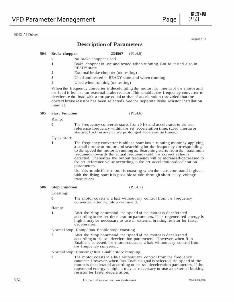
VFD Parameter Management Page 253
9000X AF Drives
August 2010
Description of Parameters
504 Brake chopper 234567 (P1.4.5)
0 No brake chopper used
1 Brake chopper in use and tested when running. Can be tested also in READY state
2 External brake chopper (no testing)
3 Used and tested in READY state and when running
4 Used when running (no testing)
When the frequency converter is decelerating the motor, the inertia of the motor and the load is fed into an external brake resistor. This enables the frequency converter to decelerate the load with a torque equal to that of acceleration (provided that the correct brake resistor has been selected). See the separate Brake resistor installation manual.
505 Start Function (P1.4.6)
Ramp:
0 The frequency converter starts from 0 Hz and accelerates to the set reference frequency within the set acceleration time. (Load inertia or starting friction may cause prolonged acceleration times.)
Flying start:
1 The frequency converter is able to start into a running motor by applying a small torque to motor and searching for the frequency corresponding to the speed the motor is running at. Searching starts from the maximum frequency towards the actual frequency until the correct value is detected. Thereafter, the output frequency will be increased/decreased to the set reference value according to the set acceleration/deceleration parameters.
Use this mode if the motor is coasting when the start command is given, with the flying start it is possible to ride through short utility voltage interruptions.
506 Stop Function (P1.4.7)
Coasting:
0 The motor coasts to a halt without any control from the frequency converter, after the Stop command.
Ramp:
1 After the Stop command, the speed of the motor is decelerated according to the set deceleration parameters. If the regenerated energy is high it may be necessary to use an external braking resistor for faster deceleration.
Normal stop: Ramp/ Run Enable stop: coasting
2 After the Stop command, the speed of the motor is decelerated according to the set deceleration parameters. However, when Run Enable is selected, the motor coasts to a halt without any control from the frequency converter.
Normal stop: Coasting/ Run Enable stop: ramping
3 The motor coasts to a halt without any control from the frequency converter. However, when Run Enable signal is selected, the speed of the motor is decelerated according to the set deceleration parameters. If the regenerated energy is high, it may be necessary to use an external braking resistor for faster deceleration.
8-52 For more information visit: www.eaton.com MN04004001E

VFD Parameter Management Page 254
9000X AF Drives
August 2010
Description of Parameters
507 DC-braking current 234567 (P1.4.8)
Defines the current injected into the motor during DC-braking.
508 DC-braking time at stop 234567 (P1.4.9)
Determines if braking is ON or OFF and the braking time of the DC-brake when the motor is stopping. The function of the DC-brake depends on the stop function, ID506.
0.0 DC-brake is not used
>0.0 DC-brake is in use and its function depends on the Stop function, (ID506). The DC-braking time is determined with this parameter.
Par. ID506 = 0; Stop function = Coasting:
After the stop command, the motor coasts to a stop without control of the frequency converter.
With DC-injection, the motor can be electrically stopped in the shortest possible time, without using an optional external braking resistor.
The braking time is scaled according to the frequency when the DC-braking starts. If the frequency is ≥ the nominal frequency of the motor, the set value of parameter ID508 determines the braking time. When the frequency is ≤10% of the nominal, the braking time is 10% of the set value of ID508.
fout fout
fn
Output Frequency
Motor Speed
DC-Braking ON
fn
0.1 x fn
t
Output Frequency Motor Speed
DC-Braking ON
t
t = 1 x ID508
t = 0.1 x ID508
RUN
STOP
RUN
STOP
Figure 8-43: DC-Braking Time when Stop Mode = Coasting
MN04004001E For more information visit: www.eaton.com 8-53

VFD Parameter Management Page 255
9000X AF Drives
August 2010
Description of Parameters
Par. ID506 = 1; Stop function = Ramp:
After the Stop command, the speed of the motor is reduced according to the set deceleration parameters, as fast as possible, to the speed defined with ID515, where the DC-braking starts.
The braking time is defined with ID508. If high inertia exists, it is recommended to use an external braking resistor for faster deceleration. See Figure 8-44.
fout
Motor Speed
Output Frequency
DC-Braking
ID515
t
t = ID508
RUN
STOP
Figure 8-44: DC-Braking Time when Stop Mode = Ramp
8-54 For more information visit: www.eaton.com MN04004001E

VFD Parameter Management Page 256
9000X AF Drives
August 2010
Description of Parameters
509 Skip frequency area 1; Low limit
510 Skip frequency area 1; High limit
511 Skip frequency area 2; Low limit
512 Skip frequency area 2; High limit
513 Skip frequency area 3; Low limit
514 Skip frequency area 3; High limit
234567 (P1.5.1)
234567 (P1.5.2)
34567 (P1.5.3)
34567 (P1.5.4)
34567 (P1.5.5)
34567 (P1.5.6)
In some systems it may be necessary to avoid certain frequencies because of mechanical resonance problems. With these parameters limits are set for the “skip frequency” regions. See Figure 8-45.
Output
Frequency
(Hz)
ID303
ID511
ID513
ID510
ID512
ID514
Reference (Hz)
Figure 8-45: Example of Skip Frequency Area Setting
515 DC-braking frequency at stop 234567 (P1.4.10)
The output frequency at which the DC-braking is applied. See Figure 8-45.
516 DC-braking time at start 234567 (P1.4.11)
DC-brake is activated when the start command is given. This parameter defines the time before the brake is released. After the brake is released, the output frequency increases according to the set start function by ID505.
MN04004001E For more information visit: www.eaton.com 8-55

VFD Parameter Management Page 257
9000X AF Drives
August 2010
Description of Parameters
518 Acceleration/deceleration ramp speed scaling ratio between skip frequency limits
234567 (P1.5.3, P1.5.7)
Defines the acceleration/deceleration time when the output frequency is between the selected skip frequency range limits (ID509 and ID510). The ramping speed (selected acceleration/deceleration time 1 or 2) is multiplied with this factor. E.g. value 0.1 makes the acceleration time 10 times shorter than outside the skip frequency range limits.
f out
(Hz)
ID518 = 0.2
ID510
(ID512; ID514)
ID509
(ID511; ID513)
ID518 = 1.2
Time (s)
Figure 8-46: Ramp Speed Scaling between Skip Frequencies
519 Flux braking current 234567 (P1.4.13)
Defines the flux braking current value. This value can be set between 0.4*IH and the Current limit.
520 Flux brake 234567 (P1.4.12)
Instead of DC braking, flux braking is a useful form of braking for motors ≤ 15 kW. When braking is needed, the frequency is reduced and the flux in the motor is increased, which in turn increases the motor’s capability to brake. Unlike DC braking, the motor speed remains controlled during braking.
The flux braking can be set ON or OFF.
0 Flux braking OFF
1 Flux braking ON
Note: Flux braking converts the energy into heat in the motor, and should be used intermittently to avoid motor damage.
8-56 For more information visit: www.eaton.com MN04004001E
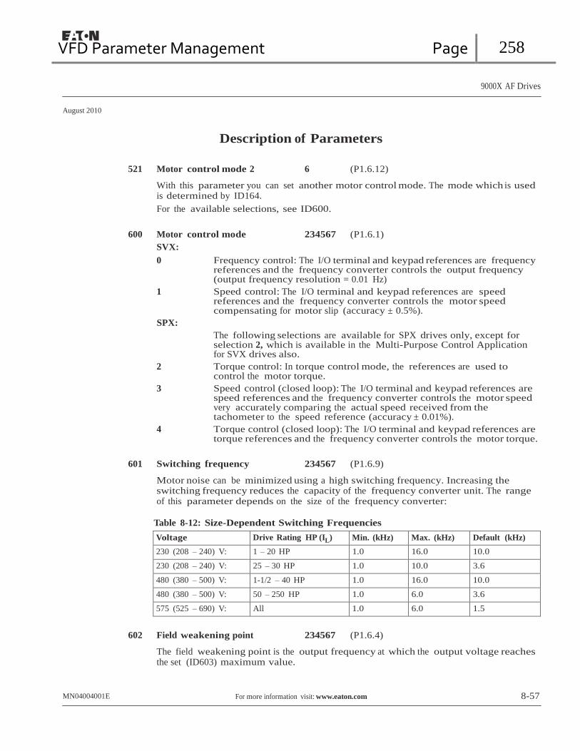
VFD Parameter Management Page 258
9000X AF Drives
August 2010
Description of Parameters
521 Motor control mode 2 6 (P1.6.12)
With this parameter you can set another motor control mode. The mode which is used is determined by ID164.
For the available selections, see ID600.
600 Motor control mode 234567 (P1.6.1)
SVX:
0 Frequency control: The I/O terminal and keypad references are frequency references and the frequency converter controls the output frequency (output frequency resolution = 0.01 Hz)
1 Speed control: The I/O terminal and keypad references are speed references and the frequency converter controls the motor speed compensating for motor slip (accuracy ± 0.5%).
SPX:
The following selections are available for SPX drives only, except for selection 2, which is available in the Multi-Purpose Control Application for SVX drives also.
2 Torque control: In torque control mode, the references are used to control the motor torque.
3 Speed control (closed loop): The I/O terminal and keypad references are speed references and the frequency converter controls the motor speed very accurately comparing the actual speed received from the tachometer to the speed reference (accuracy ± 0.01%).
4 Torque control (closed loop): The I/O terminal and keypad references are torque references and the frequency converter controls the motor torque.
601 Switching frequency 234567 (P1.6.9)
Motor noise can be minimized using a high switching frequency. Increasing the switching frequency reduces the capacity of the frequency converter unit. The range of this parameter depends on the size of the frequency converter:
Table 8-12: Size-Dependent Switching Frequencies
Voltage Drive Rating HP (IL) Min. (kHz) Max. (kHz) Default (kHz)
230 (208 – 240) V: 1 – 20 HP 1.0 16.0 10.0
230 (208 – 240) V: 25 – 30 HP 1.0 10.0 3.6
480 (380 – 500) V: 1-1/2 – 40 HP 1.0 16.0 10.0
480 (380 – 500) V: 50 – 250 HP 1.0 6.0 3.6
575 (525 – 690) V: All 1.0 6.0 1.5
602 Field weakening point 234567 (P1.6.4)
The field weakening point is the output frequency at which the output voltage reaches the set (ID603) maximum value.
MN04004001E For more information visit: www.eaton.com 8-57

VFD Parameter Management Page 259
9000X AF Drives
August 2010
Description of Parameters
603 Voltage at field weakening point
234567 (P1.6.5)
Above the frequency at the field weakening point, the output voltage remains at the set maximum value. Below the frequency at the field weakening point, the output voltage depends on the setting of the V/Hz curve parameters. See ID109, ID108, ID604 and ID605.
When the parameters ID110 and ID111 (nominal voltage and nominal frequency of the motor) are set, the parameters ID602 and ID603 are automatically set to the corresponding values. If you need different values for the field weakening point and the maximum output voltage, change these parameters after setting ID110 and ID111.
604 V/Hz curve, middle point
frequency 234567 (P1.6.6)
If the programmable V/Hz curve has been selected with ID108 this parameter defines the middle point frequency of the curve. See Figure 8-2.
605 V/Hz curve, middle point voltage
234567 (P1.6.7)
If the programmable V/Hz curve has been selected with the ID108 this parameter defines the middle point voltage of the curve. See Figure 8-2.
606 Output voltage at zero frequency
234567 (P1.6.8)
If the programmable V/Hz curve has been selected with the ID108 this parameter defines the zero frequency voltage of the curve. See Figure 8-2.
607 Overvoltage controller 234567 (P1.6.10)
These parameters allow the under-/overvoltage controllers to be switched out of operation. This may be useful, for example, if the main supply voltage varies more than -15% to +10% and the application will not tolerate this over-/undervoltage. In this case, the regulator controls the output frequency taking the supply fluctuations into account.
0 Controller switched off
1 Controller switched on (no ramping) = Minor adjustments of OP frequency are made
2 Controller switched on (with ramping) = Controller adjusts OP freq. up to max. freq.
608 Undervoltage controller 234567 (P1.6.11)
See ID607.
Note: Over-/undervoltage trips may occur when the controllers are switched off.
0 Controller switched off
1 Controller switched on
609 Torque limit 6 (P1.10.1)
With this parameter you can set the torque limit control between 0.0 – 400.0%.
8-58 For more information visit: www.eaton.com MN04004001E

VFD Parameter Management Page 260
9000X AF Drives
August 2010
Description of Parameters
610 Torque limit control P-gain 6 (P1.10.2)
This parameter defines the gain of the torque limit controller.
611 Torque limit control I-gain 6 (P1.10.3)
This parameter determines the I-gain of the torque limit controller.
612 CL: Magnetizing current 234567 (P1.6.12.1, P1.6.15.1)
Sets the motor magnetizing current (no-load current). See Page A-3.
613 CL: Speed control P-gain 234567 (P1.6.12.2, P1.6.15.2)
Sets the gain for the speed controller in % per Hz. See Page A-3.
614 CL: Speed control I-time 234567 (P1.6.12.3, P1.6.15.3)
Sets the integral time constant for the speed controller. Increasing the I-time increases stability but lengthens the speed response time. See Page A-3.
615 CL: Zero speed time at start 234567 (P1.6.12.9, P1.6.15.9)
After giving the start command the drive will remain at zero speed for the time defined by this parameter. The ramp will be released to follow the set frequency/ speed reference after this time has elapsed from the instant where the command is given. See Page A-3.
616 CL: Zero speed time at stop 234567 (P1.6.12.10, P1.6.15.10)
The drive will remain at zero speed with controllers active for the time defined by this parameter after reaching the zero speed when a stop command is given. This parameter has no effect if the selected stop function (ID506) is Coasting. See Page A-3.
617 CL: Current control P-gain 234567 (P1.6.12.17, P1.6.15.17)
Sets the gain for the current controller. This controller is active only in closed loop and advanced open loop modes. The controller generates the voltage vector reference to the modulator. See Page A-3.
618 CL: Encoder filter time 234567 (P1.6.12.18, P1.6.15.18)
Sets the filter time constant for speed measurement.
The parameter can be used to eliminate encoder signal noise. Too high a filter time reduces speed control stability. See Page A-3.
619 CL: Slip adjust 234567 P1.6.12.6, P1.6.15.6)
The motor name plate speed is used to calculate the nominal slip. This value is used to adjust the voltage of motor when loaded. The name plate speed is sometimes a little inaccurate and this parameter can therefore be used to trim the slip. Reducing the slip adjust value increases the motor voltage when the motor is loaded. See Page A-3.
MN04004001E For more information visit: www.eaton.com 8-59

VFD Parameter Management Page 261
9000X AF Drives
August 2010
Description of Parameters
620 CL: Load drooping 234567 (P1.6.12.4, P1.6.15.4)
The drooping function enables speed drop as a function of load. This parameter sets that amount corresponding to the nominal torque of the motor. See Page A-3.
621 CL: Startup torque 234567 (P1.6.12.11, P1.6.15.11)
Chooses the startup torque.
Torque Memory is used in crane applications. Startup torque FWD/REV can be used in other applications to help the speed controller. See Page A-3.
0 Not Used
1 TorqMemory
2 torque Ref
3 Torq.Fwd/Rev
626 CL: Acceleration compensation 234567 (P1.6.12.5, P1.6.15.5)
Sets the inertia compensation to improve speed response during acceleration and deceleration. The time is defined as acceleration time to nominal speed with nominal torque. This parameter is also active in advanced open loop mode.
627 CL: Magnetizing current at start 234567 (P1.6.12.7, P1.6.15.7)
628 CL: Magnetizing time at start 234567 (P1.6.12.8, P1.6.15.8)
Sets the rise time of magnetizing current.
631 Identification 23456 (P1.6.13, P1.6.16)
With this parameter, the drive will identify the motor and adjust tuning parameters to improve starting torque and closed loop current control. See Chapter 6 of the 9000X User Manual.
0 No Action
1 OL V/F Ratio-ID No Run; the drive is run at zero speed to identify the stator motor parameters.
2 OL V/F + Boost; same as ID No Run and then turns on V/Hz Boost.
3 (MultiPurpose APP, SPX Only) ID With Run; performs an ID No Run, and then runs the motor at 2/3 rated frequency to identify the motor no load current and motor saturation curve. Motor must be unloaded for an accurate ID Run.
633 CL: Start-up torque, forward 234567 (P1.6.13.5, P1.6.16.5)
Sets the start-up torque for forward direction if selected with parameter P1.6.12.11.
634 CL: Start-up torque, reverse 234567 (P1.6.13.2, P1.6.16.2)
Sets the start-up torque for reverse direction if selected with parameter P1.6.12.11.
8-60 For more information visit: www.eaton.com MN04004001E

VFD Parameter Management Page 262
9000X AF Drives
August 2010
Description of Parameters
636 Minimum frequency for Open Loop torque control
6 (P1.10.8)
Defines the frequency limit below which the frequency converter operates in the frequency control mode.
Because of the nominal slip of the motor, the internal torque calculation is inaccurate at low speeds where it is recommended to use the frequency control mode.
637 Speed controller P gain, Open
Loop 6 (P1.6.13)
Defines the P gain for the speed controlled in Open Loop control mode.
638 Speed controller I gain, Open
Loop 6 (P1.6.14)
Defines the I gain for the speed controlled in Open Loop control mode.
639 Torque controller P gain 6 (P1.10.9)
Defines the P gain of the torque controller.
640 Torque controller I gain 6 (P1.10.10)
Defines the I gain of the torque controller.
641 Torque reference selection 6 (P1.10.4)
Defines the source for torque reference.
0 Not used
1 Analog input 1
2 Analog input 2
3 Analog input 3
4 Analog input 4
5 Analog input 1 (joystick)
6 Analog input 2 (joystick)
7 From keypad, parameter R3.5
8 Fieldbus
642 Torque reference scaling,
maximum value
643 Torque reference scaling, minimum value
6 (P1.10.5)
6 (P1.10.6)
Scale the custom minimum and maximum levels for analog inputs within -300.0 – 300.0%.
MN04004001E For more information visit: www.eaton.com 8-61

VFD Parameter Management Page 263
9000X AF Drives
August 2010
Description of Parameters
644 Torque speed limit 6 (P1.10.7)
With this parameter the maximum frequency for the torque control can be selected.
0 Maximum frequency, ID102
1 Selected frequency reference
2 Preset speed 7, ID130
700 Response to the reference fault 234567 (P1.7.1)
0 No response
1 Warning
2 Warning, the frequency from 10 seconds back is set as reference
3 Warning, the Preset Frequency (ID728) is set as reference
4 Fault, stop mode after fault according to ID506
5 Fault, stop mode after fault always by coasting
A warning or a fault action and message is generated if the 4 – 20 mA reference signal is used and the signal falls below 3.5 mA for 5 seconds or below 0.5 mA for 0.5 seconds. The information can also be programmed into digital output DO1 or relay outputs RO1 and RO2.
701 Response to external fault 234567 (P1.7.3)
0 No response
1 Warning
2 Fault, stop mode after fault according to ID506
3 Fault, stop mode after fault always by coasting
A warning or a fault action and message is generated from the external fault signal in the programmable digital inputs DIN3. The information can also be programmed into digital output DO1 and into relay outputs RO1 and RO2.
702 Output phase supervision 234567 (P1.7.6)
0 No response
1 Warning
2 Fault, stop mode after fault according to ID506
3 Fault, stop mode after fault always by coasting
Output phase supervision of the motor ensures that the motor phases have approximately equal currents.
703 Earth fault protection 234567 (P1.7.7)
0 No response
1 Warning
2 Fault, stop mode after fault according to ID506
3 Fault, stop mode after fault always by coasting
Earth fault protection ensures that the sum of the motor phase currents is zero. The overcurrent protection is always working and protects the frequency converter from earth faults with high currents.
8-62 For more information visit: www.eaton.com MN04004001E

VFD Parameter Management Page 264
9000X AF Drives
August 2010
Description of Parameters
704 Motor thermal protection 234567 (P1.7.8)
0 No response
1 Warning
2 Fault, stop mode after fault according to ID506
3 Fault, stop mode after fault always by coasting
If tripping is selected the drive will stop and activate the fault stage. Deactivating this protection, i.e. setting parameter to 0, will reset the thermal stage of the motor to 0%. See Page A-4.
705 Motor thermal protection:
Motor ambient temp. factor 234567 (P1.7.9)
The factor can be set between -100.0% – 100.0%. See Page A-4.
706 Motor thermal protection:
Motor cooling factor at zero speed
234567 (P1.7.10)
The current can be set between 0 – 150.0% x InMotor. This parameter sets the value for thermal current at zero frequency. See Figure 8-47.
The default value is set assuming that there is no external fan cooling the motor. If an external fan is used this parameter can be set to 90% (or even higher).
Note: The value is set as a percentage of the motor nameplate data, ID113 (nominal current of the motor), not the drive’s nominal output current. The motor’s nominal current is the current that the motor can withstand in direct on-line use without being overheated.
If you change the parameter Nominal current of motor, this parameter is automatically restored to the default value.
Setting this parameter does not affect the maximum output current of the drive which is determined by ID107 alone. See Page A-4.
P Cooling
100%
Overload Area
IT
ID706=40%
0 fn
f
Figure 8-47: Motor Thermal Current IT Curve
MN04004001E For more information visit: www.eaton.com 8-63

VFD Parameter Management Page 265
9000X AF Drives
August 2010
Description of Parameters
707 Motor thermal protection: Time constant
234567 (P1.7.11)
This time can be set between 1 and 200 minutes.
This is the thermal time constant of the motor, the larger the motor, the longer the time constant. The time constant is the time within which the calculated thermal stage has reached 63% of its final value.
The motor thermal time is specific to the motor design and it varies between different motor manufacturers.
If the motor’s t6 – time (t6 is the time in seconds the motor can safely operate at six times the rated current) is known (given by the motor manufacturer) the time constant parameter can be set based on it. As a rule of thumb, the motor thermal time constant in minutes is equal to 2xt6. If the drive is in stop stage the time constant is internally increased to three times the set parameter value. The cooling in the stop stage is based on convection and the time constant is increased. See Figure 8-48.
Motor Temperature
Trip Area
105%
Motor
Current
I/IT
Fault/Warning
ID704
Time Constant T*
Motor Temperature
* Changes by motor size
and adjusted with ID707.
Θ = (I/IT)2 x (1-e-t/T)
Time
Figure 8-48: Motor Temperature Calculation
708 Motor thermal protection: Motor duty cycle
234567 (P1.7.12)
Defines how much of the nominal motor load is applied. The value can be set to 0% – 100%. See Page A-4.
709 Stall protection 234567 (P1.7.13)
0 No response
1 Warning
2 Fault, stop mode after fault according to ID506
3 Fault, stop mode after fault always by coasting
Setting the parameter to 0 will deactivate the protection and reset the stall time counter. See Page A-4.
8-64 For more information visit: www.eaton.com MN04004001E
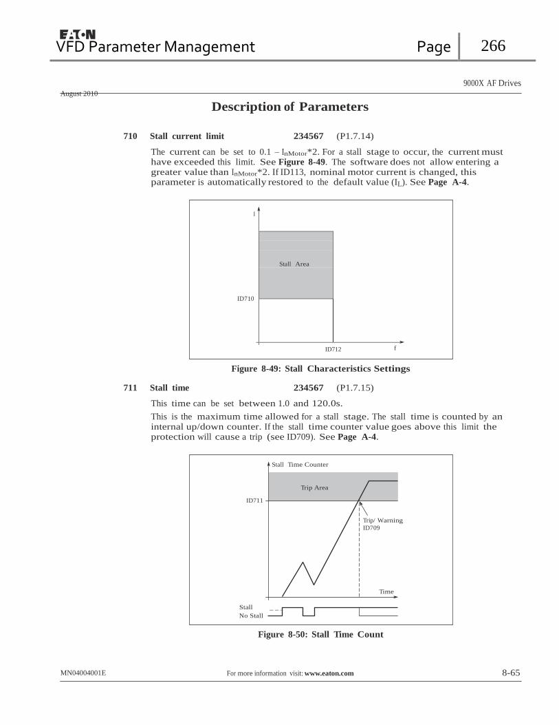
VFD Parameter Management Page 266
Stall Area
9000X AF Drives
August 2010
Description of Parameters
710 Stall current limit 234567 (P1.7.14)
The current can be set to 0.1 – InMotor*2. For a stall stage to occur, the current must have exceeded this limit. See Figure 8-49. The software does not allow entering a greater value than InMotor*2. If ID113, nominal motor current is changed, this parameter is automatically restored to the default value (IL). See Page A-4.
I
ID710
ID712 f
Figure 8-49: Stall Characteristics Settings
711 Stall time 234567 (P1.7.15)
This time can be set between 1.0 and 120.0s.
This is the maximum time allowed for a stall stage. The stall time is counted by an internal up/down counter. If the stall time counter value goes above this limit the protection will cause a trip (see ID709). See Page A-4.
Stall Time Counter
Trip Area
ID711
Trip/ Warning
ID709
Time
Stall
No Stall
Figure 8-50: Stall Time Count
MN04004001E For more information visit: www.eaton.com 8-65

VFD Parameter Management Page 267
9000X AF Drives
August 2010
Description of Parameters
712 Stall frequency limit 234567 (P1.7.16)
The frequency can be set between 1 – fmAx (ID102).
For a stall state to occur, the output frequency must have remained below this limit. See Page A-4.
713 Underload protection 234567 (P1.7.17)
0 No response
1 Warning
2 Fault, stop mode after fault according to ID506
3 Fault, stop mode after fault always by coasting
If tripping is set active the drive will stop and activate the fault stage. Deactivating the protection by setting the parameter to 0 will reset the underload time counter to zero. See Page A-5.
714 Underload protection, field weakening area load
234567 (P1.7.18)
The torque limit can be set between 10.0 – 150.0 % x TnMotor.
This parameter gives the value for the minimum torque allowed when the output frequency is above the field weakening point. See Figure 8-51.
If you change ID113, nominal motor current, this parameter is automatically restored to the default value. See Page A-5.
Torque
ID714
ID715
Underload Area
5 Hz
f
Field Weakening
Point ID602
Figure 8-51: Setting of Minimum Load
715 Underload protection, zero frequency load
234567 (P1.7.19)
The torque limit can be set between 5.0 – 150.0 % x TnMotor.
This parameter gives value for the minimum torque allowed with zero frequency. See Figure 8-51.
If you change the value of ID113, nominal motor current, this parameter is automatically restored to the default value. See Page A-5.
8-66 For more information visit: www.eaton.com MN04004001E

VFD Parameter Management Page 268
9000X AF Drives
August 2010
Description of Parameters
716 Underload time 234567 (P1.7.20)
This time can be set between 2.0 and 600.0s.
This is the maximum time allowed for an underload state to exist. An internal up/ down counter counts the accumulated underload time. If the underload counter value goes above this limit the protection will cause a trip according to ID713. If the drive is stopped the underload counter is reset to zero. See Figure 8-52 and Page A-5.
Underload Time Counter
Trip Area
ID716
Trip/ Warning ID713
Time
Underload
No Underload
Figure 8-52: Underload Time Counter Function
717 Automatic restart: Wait time 234567 (P1.8.1)
Defines the time before the frequency converter tries to automatically restart the motor after the fault has disappeared.
MN04004001E For more information visit: www.eaton.com 8-67

VFD Parameter Management Page 269
9000X AF Drives
August 2010
Description of Parameters
718 Automatic restart: Trial time 234567 (P1.8.2)
The Automatic restart function restarts the frequency converter when the faults selected with ID720 to ID725 have cleared and the waiting time has elapsed.
Wait Time Par. ID717
Wait Time Par. ID717
Wait Time Par. ID717
Fault Trigger
Motor Stop Signal
Restart 1 Restart 2
Motor Start Signal
Supervision
Fault State Active
RESET/ Fault Reset
Trial Time Par. ID718
Auto Function: (Trials = 2)
Figure 8-53: Example of Automatic Restarts with Two Restarts
ID720 to ID725 determine the maximum number of automatic restarts during the trial time set by ID718. The time count starts from the first autorestart. If the number of faults occurring during the trial time exceeds the values of ID720 to ID725 the fault state becomes active. Otherwise the fault is cleared after the trial time has elapsed and the next fault starts the trial time count again.
If a single fault remains during the trial time, a fault state is true.
719 Automatic restart: Start
function 234567 (P1.8.3)
The Start function for Automatic restart is selected with this parameter. The parameter defines the start mode:
0 Start with ramp
1 Flying start
2 Start according to ID505
8-68 For more information visit: www.eaton.com MN04004001E

VFD Parameter Management Page 270
9000X AF Drives
August 2010
Description of Parameters
720 Automatic restart: Number of tries after undervoltage fault trip
234567 (P1.8.4)
This parameter determines how many automatic restarts can be made during the trial time set by ID718 after an undervoltage trip.
0 No automatic restart
>0 Number of automatic restarts after undervoltage fault. The fault is reset and the drive is started automatically after the DC-link voltage has returned to the normal level.
721 Automatic restart: Number of
tries after overvoltage trip 234567 (P1.8.5)
This parameter determines how many automatic restarts can be made during the trial time set by ID718 after an overvoltage trip.
0 No automatic restart after overvoltage fault trip
>0 Number of automatic restarts after overvoltage fault trip. The fault is reset and the drive is started automatically after the DC-link voltage has returned to the normal level.
722 Automatic restart: Number of
tries after overcurrent trip 234567 (P1.8.6)
This parameter determines how many automatic restarts can be made during the trial time set by ID718.
Note: An IGBT temperature fault also included as part of this fault.
0 No automatic restart after overcurrent fault trip
>0 Number of automatic restarts after an overcurrent trip, saturation trip or IGBT temperature fault.
723 Automatic restart: Number of
tries after reference trip 234567 (P1.8.7)
This parameter determines how many automatic restarts can be made during the trial time set by ID718.
0 No automatic restart after reference fault trip
>0 Number of automatic restarts after the analog current signal (4 – 20 mA) has returned to the normal level (≥ 4 mA)
725 Automatic restart: Number of
tries after external fault trip 234567 (P1.8.9)
This parameter determines how many automatic restarts can be made during the trial time set by ID718.
0 No automatic restart after External fault trip
>0 Number of automatic restarts after External fault trip
MN04004001E For more information visit: www.eaton.com 8-69
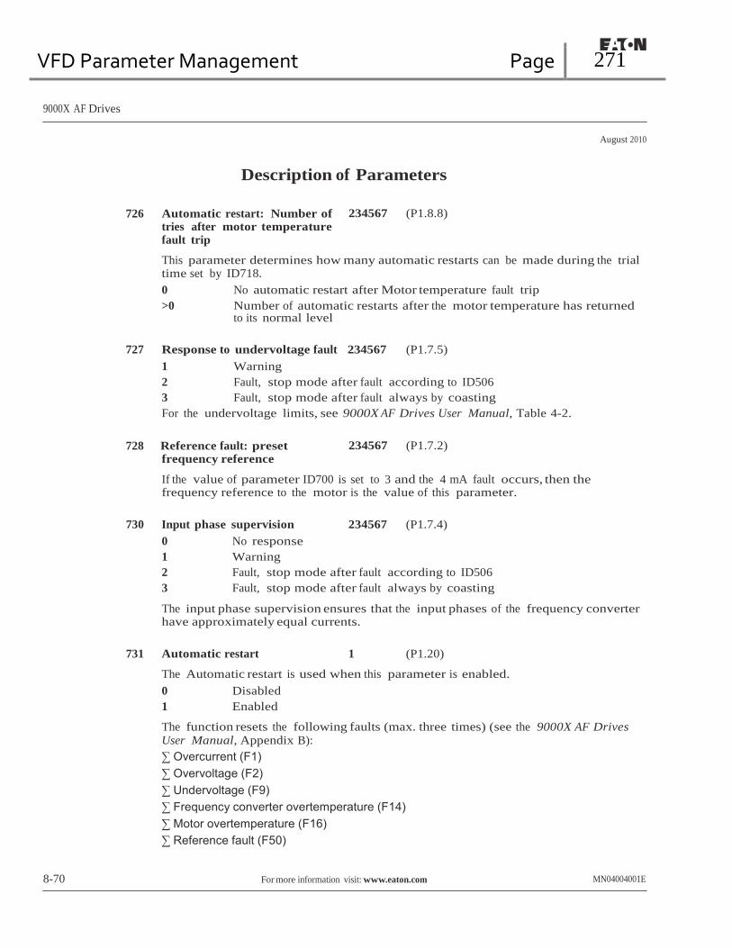
VFD Parameter Management Page 271
9000X AF Drives
August 2010
Description of Parameters
726 Automatic restart: Number of tries after motor temperature fault trip
234567 (P1.8.8)
This parameter determines how many automatic restarts can be made during the trial time set by ID718.
0 No automatic restart after Motor temperature fault trip
>0 Number of automatic restarts after the motor temperature has returned to its normal level
727 Response to undervoltage fault 234567 (P1.7.5)
1 Warning
2 Fault, stop mode after fault according to ID506
3 Fault, stop mode after fault always by coasting
For the undervoltage limits, see 9000X AF Drives User Manual, Table 4-2.
728 Reference fault: preset
frequency reference 234567 (P1.7.2)
If the value of parameter ID700 is set to 3 and the 4 mA fault occurs, then the frequency reference to the motor is the value of this parameter.
730 Input phase supervision 234567 (P1.7.4)
0 No response
1 Warning
2 Fault, stop mode after fault according to ID506
3 Fault, stop mode after fault always by coasting
The input phase supervision ensures that the input phases of the frequency converter have approximately equal currents.
731 Automatic restart 1 (P1.20)
The Automatic restart is used when this parameter is enabled.
0 Disabled
1 Enabled
The function resets the following faults (max. three times) (see the 9000X AF Drives User Manual, Appendix B):
∑ Overcurrent (F1)
∑ Overvoltage (F2)
∑ Undervoltage (F9)
∑ Frequency converter overtemperature (F14)
∑ Motor overtemperature (F16)
∑ Reference fault (F50)
8-70 For more information visit: www.eaton.com MN04004001E
VFD Parameter Management Page 272
9000X AF Drives
August 2010
Description of Parameters
732 Response to thermistor fault 234567 (P1.7.21)
0 No response
1 Warning
2 Fault, stop mode after fault according to ID506
3 Fault, stop mode after fault always by coasting
Setting the parameter to 0 will deactivate the protection.
733 Response to fieldbus fault 234567 (P1.7.22)
This sets the response mode for the fieldbus fault when a fieldbus board is used. For more information, see the respective Fieldbus Board Manual.
See ID732.
734 Response to slot fault 234567 (P1.7.23)
This sets the response mode for a board slot fault caused by a missing or failed board.
See ID732.
738 Automatic restart: Number of
tries after underload fault trip 234567 (P1.8.10)
This parameter determines how many automatic restarts can be made during the trial time set by ID718.
0 No automatic restart after an Underload fault trip
>0 Number of automatic restarts after an Underload fault trip
739 Number of PT100 inputs in use 567 (P1.7.24)
If a PT100 input board is installed in the frequency converter, this sets the number of PT100 inputs in use. See the 9000X Option Board User Manual.
Note: If the selected value is greater than the actual number of PT100 inputs being used, the display will read 200ºC. If the input is short-circuited the displayed value is -30ºC.
740 Response to PT100 fault 567 (P1.7.25)
0 No response
1 Warning
2 Fault, stop mode after fault according to ID506
3 Fault, stop mode after fault always by coasting
741 PT100 warning limit 567 (P1.7.26)
Set here the limit at which the PT100 warning will be activated.
742 PT100 fault limit 567 (P1.7.27)
Set here the limit at which the PT100 fault (F56) will be activated.
MN04004001E For more information visit: www.eaton.com 8-71
VFD Parameter Management Page 273
9000X AF Drives
August 2010
Description of Parameters
743 PT100 Numbers 2
See (P1.7.24)
6 (P1.7.28)
744
PT100 Flt Resp 2
See (P1.7.25)
6
(P1.7.29)
745
PT100 Warn Limit 2
See (P1.7.26)
6
(P1.7.30)
746
PT100 Fault Limit 2
See (P1.7.27)
6
(P1.7.31)
755
SafeDisable Mode
6
(P1.7.34)
With parameter, you set the mode of the Safe Disable.
770 Ref Fault Select 6 (P1.7.33)
With this parameter, you select the reference source to monitor for a Reference Fault.
771 FB MCW Bit 15 2, 3, 4, 5, 6, 7
Bit 15 of the Fieldbus Main Control Word is used to indicate the status of the signal from the master controller. For example, the PROFIBUS board will set Bit 15 high if the drive is addressed correctly and communicating with the master. Bit 15 is set low and the red LED on the board is turned on if: 1.) The cable is broken or incorrectly connected, 2.) The wrong configuration is set in the master, or 3.) The master is offline or shut down. Set Fault Low for this enhanced monitoring of the PROFIBUS.
This bit can affect both the Communication Fault and Reference Fault. Other Fieldbus boards or master controllers may indicate a problem by setting Bit 15 high. In this case, select Fault High to respond to a Bit 15.
850 Fieldbus reference minimum scaling
851 Fieldbus reference maximum scaling
6 (P1.9.1)
6 (P1.9.2)
Use these two parameters to scale the fieldbus reference signal. Setting value limits: 0 ≤ ID850 ≤ ID851 ≤ ID102. If ID851 = 0, custom scaling is not used and the minimum and maximum frequencies are used for scaling. The scaling functions as illustrated in Figure 8-10. See Page A-5.
Note: Using this custom scaling function also affects the scaling of the actual value.
8-72 For more information visit: www.eaton.com MN04004001E

VFD Parameter Management Page 274
9000X AF Drives
August 2010
Description of Parameters
852 to 859
Fieldbus data out selections 1 to 8
6 (P1.9.3 to P1.9.10)
Using these parameters, you can observe any monitored item or parameter from the fieldbus. Enter the ID number of the item you wish to observe for its value. See Page A-5.
Some typical values:
Table 8-13: Typical Monitored Items
Item Description Item Description
1 Output frequency 15 Digital inputs 1,2,3 status
2 Motor speed 16 Digital inputs 4,5,6 status
3 Motor current 17 Digital and relay output status
4 Motor torque 25 Frequency reference
5 Motor power 26 Analog output current
6 Motor voltage 27 AI3
7 DC link voltage 28 AI4
8 Unit temperature 31 AO1 (expander board)
9 Motor temperature 32 AO2 (expander board)
13 AI1 37 Active fault 1
14 AI2 — —
876 FB Data In1 Sel 6 (P1.9.11)
With this parameter, you select the ID of the parameter to write to with DB Data In1. The data is only sent to the drive on a change. This function is disabled if “Fieldbus” is selected in P1.10.4, Torq Ref Select.
877 FB Data In2 Sel 6 (P1.9.12)
With this parameter, you select the ID of the parameter to write to with DB Data in2. The data is only sent to the drive on a change. This function is disabled if “Fieldbus” is selected by any parameter in Group 1.2.6, Free AI Select.
1001 Number of auxiliary drives 7 (P1.9.1)
With this parameter, the number of auxiliary drives in use will be defined. The functions controlling the auxiliary drives (ID458 to ID462) can be programmed to relay outputs or digital output. By default, one auxiliary drive is in use and it is programmed to relay output RO1 at B.1.
1002 Start frequency, auxiliary drive 1
7 (P1.9.2)
The frequency of the drive controlled by the frequency converter must exceed the limit defined with these parameters with 1 Hz before the auxiliary drive is started. The 1 Hz overdraft makes a hysteresis to avoid unnecessary starts and stops. See Figure 8-54. See also ID101 and ID102.
MN04004001E For more information visit: www.eaton.com 8-73

VFD Parameter Management Page 275
9000X AF Drives
August 2010
Description of Parameters
1003 Stop frequency, auxiliary drive 1
7 (P1.9.3)
The frequency of the drive controlled by the frequency converter must fall with 1 Hz below the limit defined with these parameters before the auxiliary drive is stopped. The stop frequency limit also defines the frequency to which the frequency of the drive controlled by the frequency converter is dropped after starting the auxiliary drive. See Figure 8-54.
1004 Start frequency, auxiliary
drive 2
1005 Stop frequency, auxiliary drive 2
1006 Start frequency, auxiliary drive 3
1007 Stop frequency, auxiliary drive 3
1008 Start frequency, auxiliary drive 4
1009 Stop frequency, auxiliary drive 4
See ID1002 and ID1003.
7 (P1.9.4)
7 (P1.9.5)
7 (P1.9.6)
7 (P1.9.7)
7 (P1.9.8)
7 (P1.9.9)
8-74 For more information visit: www.eaton.com MN04004001E
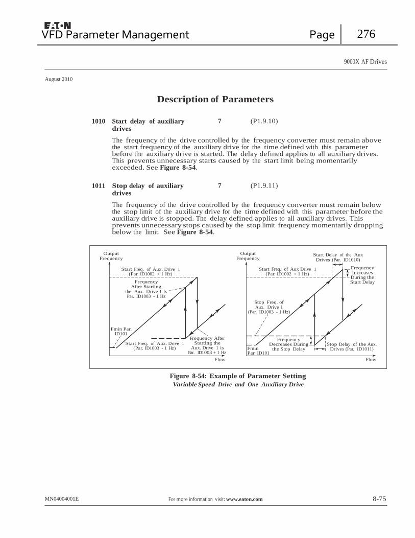
VFD Parameter Management Page 276
9000X AF Drives
August 2010
Description of Parameters
1010 Start delay of auxiliary drives
7 (P1.9.10)
The frequency of the drive controlled by the frequency converter must remain above the start frequency of the auxiliary drive for the time defined with this parameter before the auxiliary drive is started. The delay defined applies to all auxiliary drives. This prevents unnecessary starts caused by the start limit being momentarily exceeded. See Figure 8-54.
1011 Stop delay of auxiliary
drives 7 (P1.9.11)
The frequency of the drive controlled by the frequency converter must remain below the stop limit of the auxiliary drive for the time defined with this parameter before the auxiliary drive is stopped. The delay defined applies to all auxiliary drives. This prevents unnecessary stops caused by the stop limit frequency momentarily dropping below the limit. See Figure 8-54.
Output Frequency
Output Frequency
Start Delay of the Aux Drives (Par. ID1010)
Start Freq. of Aux. Drive 1
(Par. ID1002 + 1 Hz)
Frequency After Starting
the Aux. Drive 1 Is Par. ID1003 - 1 Hz
Start Freq. of Aux Drive 1
(Par. ID1002 + 1 Hz)
Stop Freq. of Aux. Drive 1
(Par. ID1003 - 1 Hz)
Frequency Increases
During the Start Delay
Fmin Par.
ID101
Start Freq. of Aux. Drive 1 (Par. ID1003 - 1 Hz)
Frequency After
Starting the Aux. Drive 1 is
Fmin
Frequency
Decreases During the Stop Delay
Stop Delay of the Aux.
Drives (Par. ID1011) Par. ID1003 + 1 Hz
Flow
Par. ID101 Flow
Figure 8-54: Example of Parameter Setting
Variable Speed Drive and One Auxiliary Drive
MN04004001E For more information visit: www.eaton.com 8-75

VFD Parameter Management Page 277
9000X AF Drives
August 2010
Description of Parameters
1012 Reference step after start of auxiliary drive 1
1013 Reference step after start of auxiliary drive 2
1014 Reference step after start of auxiliary drive 3
1015 Reference step after start of auxiliary drive 4
7 (P1.9.12)
7 (P1.9.13)
7 (P1.9.14)
7 (P1.9.15)
The reference step will always be automatically added to the reference value when the corresponding auxiliary drive is started. With the reference steps, e.g. the pressure loss in the piping caused by the increased flow can be compensated. See Figure 8-55.
Reference for PI-Controller
Reference Step 3 ID1014
Reference Step 2
ID1013
Reference Step 1 ID1012
Reference (Analog
Input)
Time
Aux. Drive 1
Aux. Drive 2
Aux. Drive 3
Stop
Start
Stop
Start
Stop
Start
Figure 8-55: Reference Steps after Starting Auxiliary Drives
1016 Sleep frequency 57 (P1.1.15)
The frequency converter is automatically stopped if the frequency of the drive falls below the Sleep level defined with this parameter for a time greater than that determined by ID1017. During the Stop state, the PID controller is operating switching the frequency converter back to the Run state when the actual value signal either falls below or exceeds (ID1019) the Wake-up level determined by ID1018. See Figure 8-56.
8-76 For more information visit: www.eaton.com MN04004001E

VFD Parameter Management Page 278
9000X AF Drives
August 2010
Description of Parameters
1017 Sleep delay 57 (P1.1.16)
The minimum amount of time the frequency has to remain below the Sleep level before the frequency converter is stopped. See Figure 8-56.
1018 Wake-up level 57 (P1.1.17)
The wake-up level defines the level below which the actual value must fall or which has to be exceeded before the Run state of the frequency converter is restored. See Figure 8-56.
Actual
Value
Wake-Up Level
(ID1018)
Time
Output
Frequency
t ID1017 t ID1017
Sleep Level
ID1016
Time
Start/Stop Status of
the Var. Speed Drive
Running
Stop
Figure 8-56: Frequency Converter Sleep Function
1019 Wake-up function 57 (P1.1.18)
This parameter defines whether the restoration of the Run state occurs when the actual value signal falls below or exceeds the Wake-up level (ID1018). See Figure 8-56 and Table 8-14.
Application 5 has selections 0 – 1 and Application 7 selections 0 – 3 available.
MN04004001E For more information visit: www.eaton.com 8-77
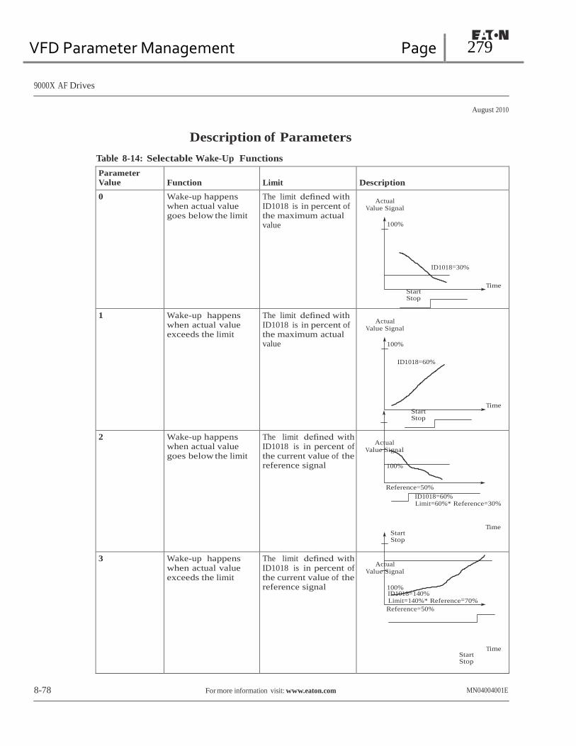
VFD Parameter Management Page 279
9000X AF Drives
August 2010
Description of Parameters
Table 8-14: Selectable Wake-Up Functions
Parameter Value
Function
Limit
Description
0 Wake-up happens when actual value goes below the limit
The limit defined with ID1018 is in percent of the maximum actual value
Actual
Value Signal
100%
ID1018=30%
Time
Start Stop
1 Wake-up happens when actual value exceeds the limit
The limit defined with ID1018 is in percent of the maximum actual value
Actual
Value Signal
100%
ID1018=60%
Time Start Stop
2 Wake-up happens when actual value goes below the limit
The limit defined with ID1018 is in percent of the current value of the reference signal
Actual
Value Signal
100%
Reference=50%
ID1018=60% Limit=60%* Reference=30%
Time
Start Stop
3 Wake-up happens when actual value exceeds the limit
The limit defined with ID1018 is in percent of the current value of the reference signal
Actual
Value Signal
100% ID1018=140% Limit=140%* Reference=70%
Reference=50%
Time
Start Stop
8-78 For more information visit: www.eaton.com MN04004001E
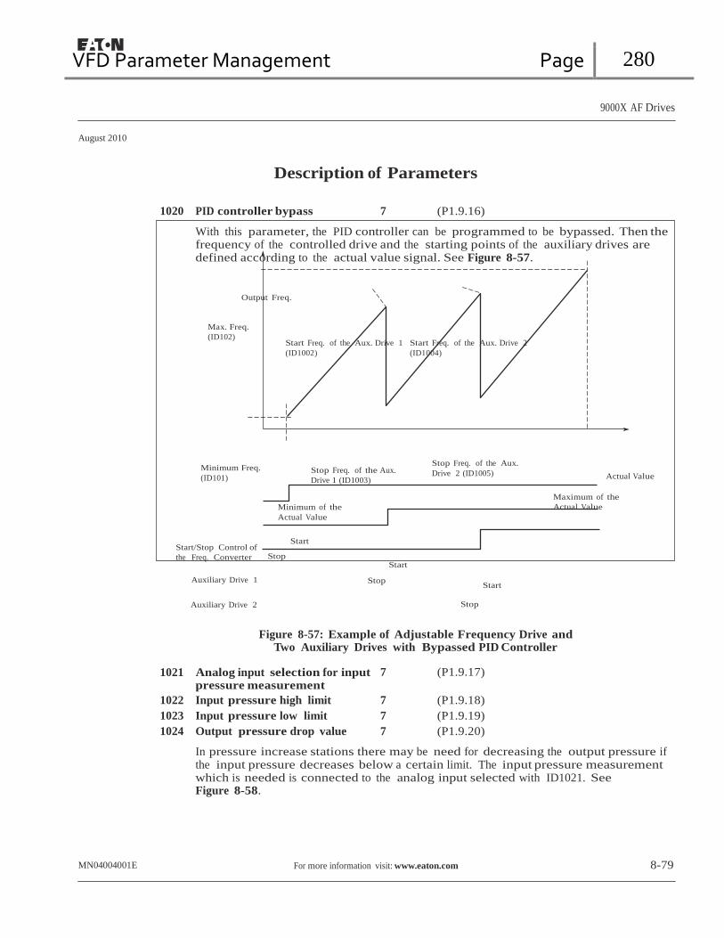
VFD Parameter Management Page 280
9000X AF Drives
August 2010
Description of Parameters
1020 PID controller bypass 7 (P1.9.16)
With this parameter, the PID controller can be programmed to be bypassed. Then the frequency of the controlled drive and the starting points of the auxiliary drives are defined according to the actual value signal. See Figure 8-57.
Output Freq.
Max. Freq.
(ID102)
Start Freq. of the Aux. Drive 1
(ID1002)
Start Freq. of the Aux. Drive 2
(ID1004)
Minimum Freq.
(ID101)
Stop Freq. of the Aux.
Drive 1 (ID1003)
Minimum of the
Actual Value
Stop Freq. of the Aux.
Drive 2 (ID1005) Actual Value
Maximum of the
Actual Value
Start/Stop Control of
the Freq. Converter Stop
Auxiliary Drive 1
Auxiliary Drive 2
Start
Stop
Start
Stop
Start
Figure 8-57: Example of Adjustable Frequency Drive and
Two Auxiliary Drives with Bypassed PID Controller
1021 Analog input selection for input pressure measurement
7 (P1.9.17)
1022 Input pressure high limit 7 (P1.9.18)
1023 Input pressure low limit 7 (P1.9.19)
1024 Output pressure drop value 7 (P1.9.20)
In pressure increase stations there may be need for decreasing the output pressure if the input pressure decreases below a certain limit. The input pressure measurement which is needed is connected to the analog input selected with ID1021. See Figure 8-58.
MN04004001E For more information visit: www.eaton.com 8-79

VFD Parameter Management Page 281
9000X AF Drives
August 2010
Description of Parameters
Input Pressure Measurement Selected with ID1021
PI-Controller Actual Value Input ID333
M
Figure 8-58: Input and Output Pressure Measuring
ID1022 and ID1023 are used to select the limits for the area of the input pressure, where the output pressure is decreased. The values are in percent of the input pressure measurement maximum value. With ID1024 the value for the output pressure decrease within this area can be set. The value is in percent of the reference value maximum. See Figure 8-59.
Output Pressure
ID1024 Output Pressure Drop Value
Time
Input Pressure
ID1026 Input Pressure High Limit
ID1032 Input Pressure Low Limit
Time
Figure 8-59: Output Pressure Behavior Depending on
Input Pressure and Parameter Settings
8-80 For more information visit: www.eaton.com MN04004001E

VFD Parameter Management Page 282
9000X AF Drives
August 2010
Description of Parameters
1025 Frequency drop delay after starting auxiliary drive
1026 Frequency increase delay after stopping auxiliary drive
7 (P1.9.21)
7 (P1.9.22)
If the speed of auxiliary drive increases slowly (e.g. in soft starter control) then a delay between the start of auxiliary drive and the frequency drop of the adjustable frequency drive will make the control smoother. This delay can be adjusted with ID1025.
In the same way, if the speed of the auxiliary drives decreases slowly a delay between the auxiliary drive stop and the frequency increase of the adjustable frequency drive can be programmed with ID1026. See Figure 8-60.
If either of the values of ID1025 or ID1026 is set to maximum (300.0 s) no frequency drop nor increase takes place.
Output Frequency
Start Freq. of Aux Drive + 1 Hz
Stop Freq. of
Aux Drive – 1 Hz
Start Delay of Aux. Drive (ID1010)
Aux. Drive
Control
Frequency Drop Delay
(ID1025) Stop Delay
of Aux. Drive (ID1011)
Time
Frequency Increase Delay
(ID1026)
Aux. Drive
Speed
Figure 8-60: Frequency Drop and Increase Delays
1027 Autochange 7 (P1.9.24)
0 Autochange not used
1 Autochange used
MN04004001E For more information visit: www.eaton.com 8-81
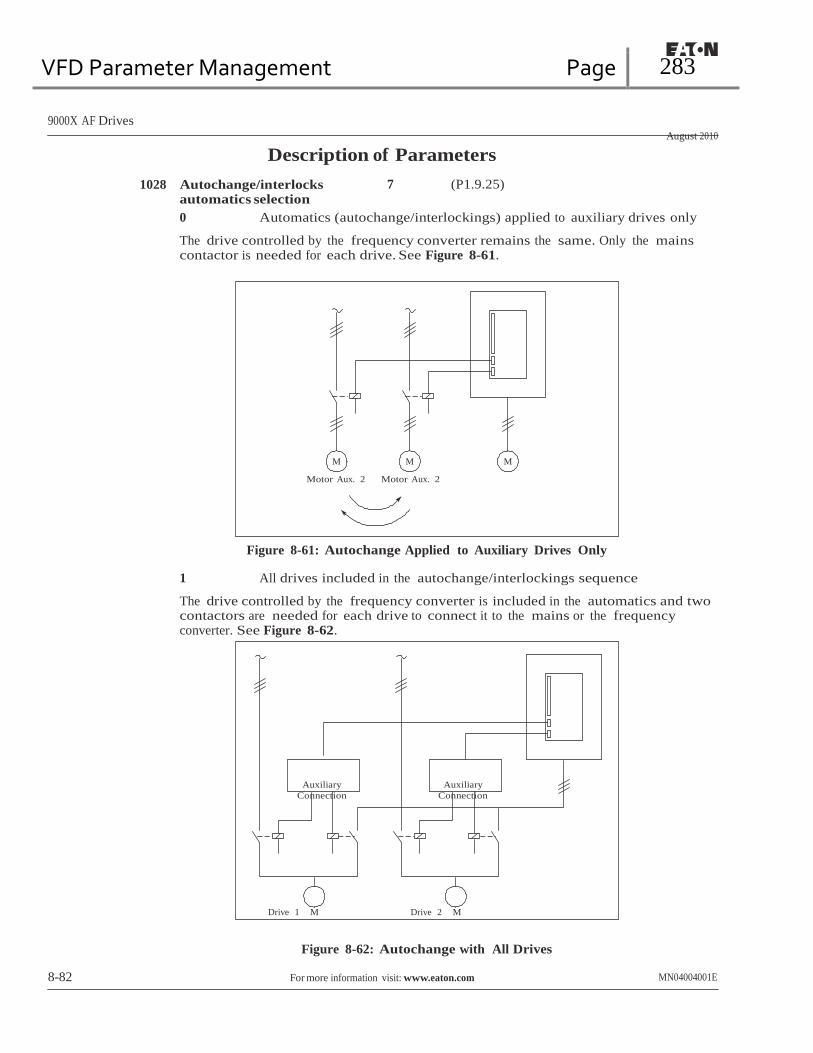
VFD Parameter Management Page 283
9000X AF Drives
August 2010
Description of Parameters
1028 Autochange/interlocks automatics selection
7 (P1.9.25)
0 Automatics (autochange/interlockings) applied to auxiliary drives only
The drive controlled by the frequency converter remains the same. Only the mains contactor is needed for each drive. See Figure 8-61.
M
Motor Aux. 2
M M
Motor Aux. 2
Figure 8-61: Autochange Applied to Auxiliary Drives Only
1 All drives included in the autochange/interlockings sequence
The drive controlled by the frequency converter is included in the automatics and two contactors are needed for each drive to connect it to the mains or the frequency converter. See Figure 8-62.
Auxiliary
Connection
Auxiliary
Connection
Drive 1 M Drive 2 M
Figure 8-62: Autochange with All Drives
8-82 For more information visit: www.eaton.com MN04004001E

VFD Parameter Management Page 284
9000X AF Drives
August 2010
Description of Parameters
1029 Autochange interval 7 (P1.9.26)
After the expiration of the time defined with this parameter, the autochange function takes place if the capacity used lies below the level defined with ID1031 (Autochange frequency limit) and ID1030 (Maximum number of auxiliary drives). Should the capacity exceed the value of ID1031, the autochange will not take place before the capacity goes below this limit.
• The time count is activated only if the Start/Stop request is active.
• The time count is reset after the autochange has taken place.
See Figure 8-63.
1030 Maximum number of auxiliary
drives 7 (P1.9.27)
1031 Autochange frequency limit 7 (P1.9.28)
These parameters define the level below which the capacity used must remain for autochange to take place.
This level is defined as follows:
• If the number of running auxiliary drives is smaller than the value of ID1030 the autochange function can take place.
• If the number of running auxiliary drives is equal to the value of ID1030 and the frequency of the controlled drive is below the value of ID1031 the autochange can take place.
• If the value of ID1031 is 0.0 Hz, the autochange can take place only in rest position (Stop and Sleep) regardless of the value of ID1030.
Output Frequency
ID1030=1
Max. Number of Auxiliary Drives
Autochange Moment
ID1031
Autochange Level,
Frequency
ID1029
Autochange Interval
ID1029
Autochange Interval
Aux. Drive 1 Control
Aux. Drive 2 Control
Figure 8-63: Autochange Interval and Limits
MN04004001E For more information visit: www.eaton.com 8-83
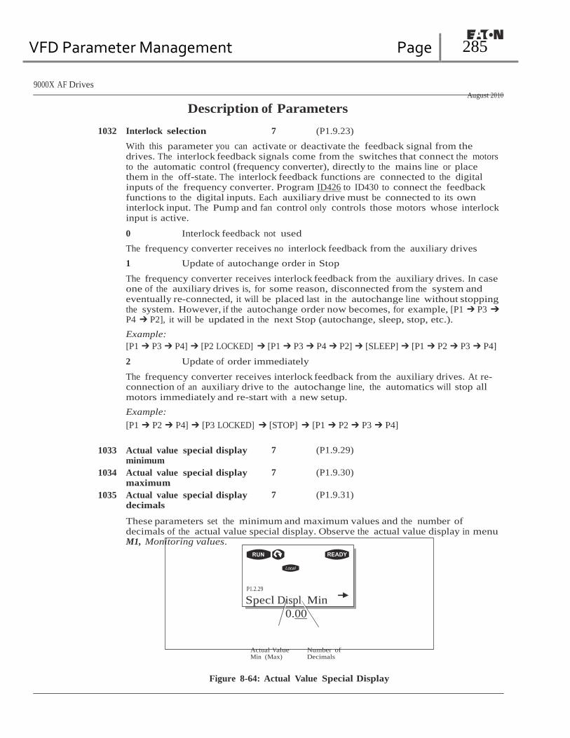
VFD Parameter Management Page 285
9000X AF Drives
August 2010
Description of Parameters
1032 Interlock selection 7 (P1.9.23)
With this parameter you can activate or deactivate the feedback signal from the drives. The interlock feedback signals come from the switches that connect the motors to the automatic control (frequency converter), directly to the mains line or place them in the off-state. The interlock feedback functions are connected to the digital inputs of the frequency converter. Program ID426 to ID430 to connect the feedback functions to the digital inputs. Each auxiliary drive must be connected to its own interlock input. The Pump and fan control only controls those motors whose interlock input is active.
0 Interlock feedback not used
The frequency converter receives no interlock feedback from the auxiliary drives
1 Update of autochange order in Stop
The frequency converter receives interlock feedback from the auxiliary drives. In case one of the auxiliary drives is, for some reason, disconnected from the system and eventually re-connected, it will be placed last in the autochange line without stopping the system. However, if the autochange order now becomes, for example, [P1 ➔ P3 ➔ P4 ➔ P2], it will be updated in the next Stop (autochange, sleep, stop, etc.).
Example:
[P1 ➔ P3 ➔ P4] ➔ [P2 LOCKED] ➔ [P1 ➔ P3 ➔ P4 ➔ P2] ➔ [SLEEP] ➔ [P1 ➔ P2 ➔ P3 ➔ P4]
2 Update of order immediately
The frequency converter receives interlock feedback from the auxiliary drives. At re- connection of an auxiliary drive to the autochange line, the automatics will stop all motors immediately and re-start with a new setup.
Example:
[P1 ➔ P2 ➔ P4] ➔ [P3 LOCKED] ➔ [STOP] ➔ [P1 ➔ P2 ➔ P3 ➔ P4]
1033 Actual value special display
minimum
1034 Actual value special display maximum
1035 Actual value special display decimals
7 (P1.9.29)
7 (P1.9.30)
7 (P1.9.31)
These parameters set the minimum and maximum values and the number of decimals of the actual value special display. Observe the actual value display in menu M1, Monitoring values.
P1.2.29
Specl Displ Min
0.00
Actual Value Min (Max)
Number of Decimals
Figure 8-64: Actual Value Special Display

VFD Parameter Management Page 286
9000X AF Drives
August 2010
Description of Parameters
1354 FB WatchdogDelay 6 (P1.7.32)
With this parameter, you activate the WatchDog timer. If bit 11 of the Main Control Word stops cycling for this set period of time, an FB Communication Fault occurs.
1522 High Speed Mode 6 (P1.4.14)
Changes maximum fundamental output frequency from 320.0 Hz to 600.0 Hz.
1680 Safe Disable 6 (P1.3.3.29)
With this parameter, you select the digital output to show the status of the Safe Disable. (Requires SPX drive and special card in Slot B.)
1681 ChargeSWState 6 (P1.3.3.30)
With this parameter, you select the digital output to show the status of the DC Bus charge. Can be used to close contactor when CPX precharge is complete.
1685 LoRemButtonActive 234567
With this parameter, you can disable the local remote button on the keypad if a digital input is used to select local and remote mode.
1686 CPX Temperature Fault 6 (P1.2.7.22)
Contact open: Fault is displayed and motor stopped.
1707 Hide Operate Menu 234567
With this parameter, you can disable the Keypad Operate Menu so the Multimonitor Menu can be used to display three monitor values at a time. if one of the values is a reference, the up/down arrows will adjust the reference as with the Operate Menu.
MN04004001E For more information visit: www.eaton.com 8-85
VFD Parameter Management Page 287
9000X AF Drives
August 2010
Description of Parameters Keypad Control Parameters
Unlike the parameters listed above, these parameters are located in the M2 menu of the control keypad. The reference parameters do not have an ID number.
114 STOP button activated (P2.4, P2.6)
To make the STOP button a “hotspot” which always stops the drive regardless of the selected control place, set the value of this parameter to 1.
See also ID125.
123 Keypad direction (P2.3)
0 Forward: The rotation of the motor is forward, when the keypad is the active control place.
1 Reverse: The rotation of the motor is reversed, when the keypad is the active control place.
For more information, see the 9000X AF Drives User Manual, Chapter 5, Keypad Control Menu (M2).
R3.2 Keypad reference (R2.2)
The frequency reference can be adjusted from the keypad with this parameter.
The output frequency can be copied as the keypad reference by pushing the STOP button for 3 seconds when you are on any of the pages of menu M2. For more information, see the 9000X AF Drives User Manual, Chapter 5, Keypad Control Menu (M2).
R3.4 PID reference 1 57 (R2.4)
The PID controller keypad reference can be set between 0% and 100%. This reference value is the active PID reference if ID332 = 2.
R3.5 PID reference 2 57 (R2.5)
The PID controller keypad reference 2 can be set between 0% an 100%. This reference is active if the DIN5 function = 13 and the DIN5 contact is closed.
R3.5 Torque reference 6 (R2.5)
Defines the torque reference from 0.0 to 100.0%.
1688 Operate Menu Hide — Disables operate menu to use monitor menu without auto
return to operate.
8-86 For more information visit: www.eaton.com MN04004001E

VFD Parameter Management Page 288
9000X AF Drives
August 2010
Appendix A — Additional Information In this chapter you will find additional information on special parameter groups. Such
groups are:
● Parameters of External Brake Control with Additional Limits (see below)
● Closed Loop Parameters (see Page A-3)
● Advanced Open Loop Parameters (see Page A-4)
● Parameters of Motor Thermal Protection (see Page A-4)
● Parameters of Stall Protection (see Page A-4)
● Parameters of Underload Protection (see Page A-5)
● Fieldbus Control Parameters (see Page A-5)
External Brake Control with Additional Limits
ID315, ID316, ID346 to ID349, ID352, ID353
The external brake used for additional braking can be controlled through ID315, ID316, ID346
to ID349 and ID352/ID353. Selecting On/Off Control for the brake, defining the frequency or
torque limit(s) the brake should react to and defining the Brake-On/-Off delays will allow an
effective brake control. See Figure A-1.
Torque Limit ID349
Frequency Limit ID347
START STOP
Brake Off Brake On
Brake-Off
Delay; ID352
Brake-On Delay;
ID353
Figure A-1: Brake Control with Additional Limits
In Figure A-1 the brake control is set to react to both the torque supervision limit (ID349) and
frequency supervision limit (ID347). Additionally, the same frequency limit is used for both
brake-off and brake-on control by giving ID346 the value 4. Use of two different frequency
limits is also possible. Then ID315 and ID346 must be given the value 3.
Brake-off: In order for the brake to release, three conditions must be fulfilled: 1) the drive
must be in Run state, 2) the torque must be over the set limit (if used) and 3) the output
frequency must be over the set limit (if used).
MN04004001E For more information visit: www.eaton.com A-1

VFD Parameter Management Page 289
9000X AF Drives
August 2010
Appendix A
Brake-on: Stop command activates the brake delay count and the brake is closed when the
output frequency falls below the set limit (ID315 or ID346). As a precaution, the brake closes
when the brake-on delay expires, at the latest.
Note: A fault or Stop state will close the brake immediately without a delay.
See Figure A-2.
Note: It is strongly advisable that the brake-on delay be set longer than the ramp time in
order to avoid damaging of the brake.
No brake-off control
ID346 Brake-off ctrl, 2 limits Brake-on/off ctrl, 1 limit
0-2
3 4
Brake-Off Control
TRUE
Output Frequency ≥ ID347
0-2
3-4
No brake-off control
ID348 Brake-off control, torque limit
0-2 3
And
Off-
Delay Count
TRUE
Motor Torque ≥ ID349
0-2
3-4
Run State
No Run Request
Reversing Or
No Run Request
On- Delay Count
Not
Brake Off
Brake On
Brake-On Control
ID315
ID346
No brake-on control
Brake-on ctrl, 2 limits
No brake-on control
Brake-on/off ctrl, 1 limit
0-2
3 3
Or
0-3
4
4
Or
And
ID316
ID347
0-3
4
Output
Frequency ≤
Fault
Figure A-2: Brake Control Logic
A-2 For more information visit: www.eaton.com MN04004001E

VFD Parameter Management Page 290
9000X AF Drives
August 2010
Closed Loop Parameters
ID612 to ID621
Appendix A
Select the Closed loop control mode by setting value 3 or 4 for ID600.
Closed loop control mode (see Page 8-57) is used when enhanced performance near zero
speed and better static speed accuracy with higher speeds are needed. Closed loop control
mode is based on “rotor flux oriented current vector control”. With this controlling principle,
the phase currents are divided into a torque producing current portion and a magnetizing
current portion. Thus, the squirrel cage induction machine can be controlled in a fashion of
a separately excited DC motor.
Note: These parameters can be used with SVXP drive only.
Example: Motor Control Mode = 3 (Closed loop speed control)
This is the usual operation mode when fast response times, high accuracy or controlled run
at zero frequencies are needed. Encoder board should be connected to slot C of the control
unit. Set the encoder P/R-parameter (P7.3.1.1). Run in open loop and check the encoder speed
and direction (V7.3.2.2). Change the direction parameter (P7.3.1.2) or switch the phases of
motor cables if necessary. Do not run if encoder speed is wrong. Program the no-load current
to ID612 and set ID619 (Slip Adjust) to get the voltage slightly above the linear V/Hz-curve
with the motor frequency at about 66% of the nominal motor frequency. The Motor Nominal
Speed parameter (ID112) is critical. The Current Limit parameter (ID107) controls the
available torque linearly in relative to motor nominal current.
MN04004001E For more information visit: www.eaton.com A-3

VFD Parameter Management Page 291
9000X AF Drives
August 2010
Appendix A
Parameters of Motor Thermal Protection
ID704 to ID708
General
The motor thermal protection is to protect the motor from overheating. The Eaton drive is
capable of supplying higher than nominal current to the motor. If the load requires this high
current there is a risk that the motor will be thermally overloaded. This is the case especially
at low frequencies. At low frequencies the cooling effect of the motor is reduced as well as its
capacity. If the motor is equipped with an external fan the load reduction at low speeds is
small.
The motor thermal protection is based on a calculated model and it uses the output current
of the drive to determine the load on the motor.
The motor thermal protection can be adjusted with parameters. The thermal current IT
specifies the load current above which the motor is overloaded. This current limit is a
function of the output frequency.
The thermal stage of the motor can be monitored on the control keypad display. See 9000X
AF Drives User Manual, Chapter 5.
CAUTION
The calculated model does not protect the motor if the airflow to
the motor is reduced by blocked air intake grill.
Parameters of Stall Protection
ID709 to ID712
General
The motor stall protection protects the motor from short time overload situations such as
one caused by a stalled shaft. The reaction time of the stall protection can be set shorter than
that of motor thermal protection. The stall state is defined with two parameters, ID710 (Stall
current) and ID712 (Stall frequency limit). If the current is higher than the set limit and output
frequency is lower than the set limit, the stall state is true. There is actually no real indication
of the shaft rotation. Stall protection is a type of overcurrent protection.
A-4 For more information visit: www.eaton.com MN04004001E

VFD Parameter Management Page 292
9000X AF Drives
August 2010
Parameters of Underload Protection
ID713 to ID716
Appendix A
General
The purpose of the motor underload protection is to ensure that there is load on the motor
when the drive is running. If the motor loses its load there might be a problem in the process,
e.g. a broken belt or a dry pump.
Motor underload protection can be adjusted by setting the underload curve with parameters
ID714 (Field weakening area load) and ID715 (Zero frequency load), see below. The underload
curve is a squared curve set between the zero frequency and the field weakening point. The
protection is not active below 5 Hz (the underload time counter is stopped).
The torque values for setting the underload curve are set in percentage which refers to the
nominal torque of the motor. The motor’s name plate data. parameter motor nominal current
and the drive’s nominal current IH are used to find the scaling ratio for the internal torque
value. If other than nominal motor is used with the drive, the accuracy of the torque
calculation decreases.
Fieldbus Control Parameters
ID850 to ID859
The Fieldbus control parameters are used when the frequency or the speed reference comes
from the fieldbus (Modbus, Profibus, DeviceNet, etc.). With the Fieldbus Data Out Selection
1 – 8, you can monitor values from the fieldbus.
MN04004001E For more information visit: www.eaton.com

VFD Parameter Management Page 293
Eaton’s Electrical Sector is a global leader in power distribution, power quality, control and automation, and monitoring products. When combined with Eaton’s full-scale engineering services, these products provide customer-driven PowerChain Management solutions to serve the power system needs of the data center, industrial, institutional, public sector, utility, commercial, residential, IT, mission critical, alternative energy and OEM markets worldwide.
PowerChain Management solutions help enterprises achieve sustainable and competitive advantages through proactive management of the power system as a strategic, integrated asset throughout its life cycle, resulting in enhanced safety, greater reliability and energy efficiency. For more information, visit www.eaton.com/electrical.

VFD Parameter Management Page 294
PROFIBUS Module
The BradCommunications™ Direct-Link™ network
adapters provide simple use and fast implementation in
connecting notebook or desktop computers with Profibus
protocols up to 12 Mbps.
Features
• RoHS compliant
08 Jul. 09
DW2007191 Direct-Link™ USB100PFB
Easy-to-Use solution
• Ready to plug, no hardware setting
• High Speed USB Adapter v2.0 &
v1.1
• Profibus protocols managed
simultaneously:
… Profibus DP-V0 Master/Slave
… Profibus DP-V1 Master
… S7/MPI Master
for Simatic®
S7 -300 and S7-400
… S7/MPI Slave
for Simatic®
S7-200
… S5 for Simatic®
S5
(95U, 115U, 135U, 155U)
• Profibus speed: 9.6kbps 12Mbps
• Software Interfaces:
… OPC Server
(Data Access v1.0a, v2.05 and
3.0)
… Wonderware DAServer
… Wonderware I/O Server
(SuiteLink, FastDDE)
… ActiveX Control
… DLL library 32-bits
… VI ( Virtual Instruments for NI
LabVIEW™)
Supported OS
• Windows XP / 2000 / 2003 Server
DLL
Molex is a member of PTO (PROFIBUS Trade Organization), PNO (PROFIBUS Nutzerorganisation e. V.) and France Profibus.
Overview
The BradCommunications™ Direct-Link™ is a range of automation components for industrial communication. It includes a variety of products such as diagnostic tools, intelligent connectors, tunneling gateways, dedicated fieldbus cards, and software drivers for industrial networks.
Simple as they are affordable, Direct-Link™ products allow you to acquire the equipment to develop your architectures and industrial applications at a lower cost. The BradCommunications™ Direct-Link™ product line is characterized by its simple use and fast implementation. The solutions are modular and scalable. Moreover, the products are designed to be easily embedded in computerized systems and are available in a wide selection of form factors. Particularly, the BradCommunications™ Direct-Link™ products are based on a non-intelligent 12 Mbps USB adapters that are especially designed to communicate with Siemens controllers and others compatibles devices set on a Profibus network. Direct-Link™ suits perfectly to applications requiring few CPU resources (for more powerful data through and large application, see applicom
®
product ranges).

VFD Parameter Management Page 295
Hardware
Unit High-speed USB Adapter, Version 2.0 or 1.1 Full speed and High Speed with automatic recognition
Processor USB : ARM 7, Philips LPC2212
Profibus : 186 core, 48 MHz Dimensions (L x W x H)
56 x 33 x 93mm (2.20“ x 1.29“ x 3.66“), Aluminium box
Power supply 5V through USB (no external supply required) Consumption 350 mA USB connector USB Port Type: Mini-B
USB Cable A/Mini-B (included in the package) Operating T° 0°C to +55°C (32°F to 131°F) Storage T° -20°C to +70°C (-4°F to 158°F) RoHS Yes Humidity 5 to 95% non condensing Certification CE, UL, UL/C
Supported Protocols
Protocol • S7/MPI(1)
Master - Siemens S7-300, S7-400
• MPI(1)
Slave - Siemens S7-200
• DP-V0 Master/Slave Class-1 & Class-2
(3070 bytes INPUT and 3070 bytes OUTPUT)
• DP-V1 Master Class-1 & Class-2
• S5(1)
Client – Siemens 95U, 115U, 135U, 155U Profibus port
Port type Profibus port (EN 50170) Connector type 9 pin, D-sub, female Electrical Interface
RS485 with galvanic insulation 500 V
Speed 9600 bps to 12 Mbps LED indicators 2 bicolor leds: Bus fault, Communication status
Part Number Description DRL-MPI-USB
BradCommunications™ Direct-Link™ High-Speed USB Adapter for MPI/S7, PROFIBUS
® up to 12 Mb, All Data Servers (OPC,
Wonderware™
, ActiveX™
) and DLL Library
DRL-MPI-USB-DLL BradCommunications™ Direct-Link™ High-Speed USB Adapter for
MPI/S7, PROFIBUS®
up to 12 Mb, DLL Library only DRL-PFB-USB
BradCommunications™ Direct-Link™ High-Speed USB Adapter for Full PROFIBUS
® (DP, S5, S7/MPI), Profibus up to 12 Mb, All Data
Servers (OPC, Wonderware™
, ActiveX™
) and DLL Library DRL-PFB-USB-DLL
BradCommunications™ Direct-Link™ High-Speed USB Adapter for
Full PROFIBUS®
(DP, S5, S7/MPI), Profibus up to 12 Mb, DLL Library only
DRL-UDS-USB Upgrade license from DLL Library only € All Data Servers (OPC,
Wonderware™
, ActiveX™
) and DLL Library
Direct-Link™ USB100PFB
Software tools Technical data
The core of Direct-Link™ PC Network Interfaces lies in effective software tools enabling fast integration of industrial communication into your applications.
Configuration
Diagnostics
Testing Tools (1) – Maximum of 40 Simatic
® S7 and S5 devices supported simultaneously.
Ordering information

VFD Parameter Management Page 296
PROFIBUS
Protocol manual
Profibus DRL-MPI-USB DRL-PFB-USB
Direct-Link™ PC Network Interfaces
Molex Automation and Electrical Product (AEP) division
1
Copyright © Molex Automation and Electrical Product (AEP). All rights reserved.

VFD Parameter Management Page 297
2
Copyright © Molex Automation and Electrical Product (AEP). All rights reserved.
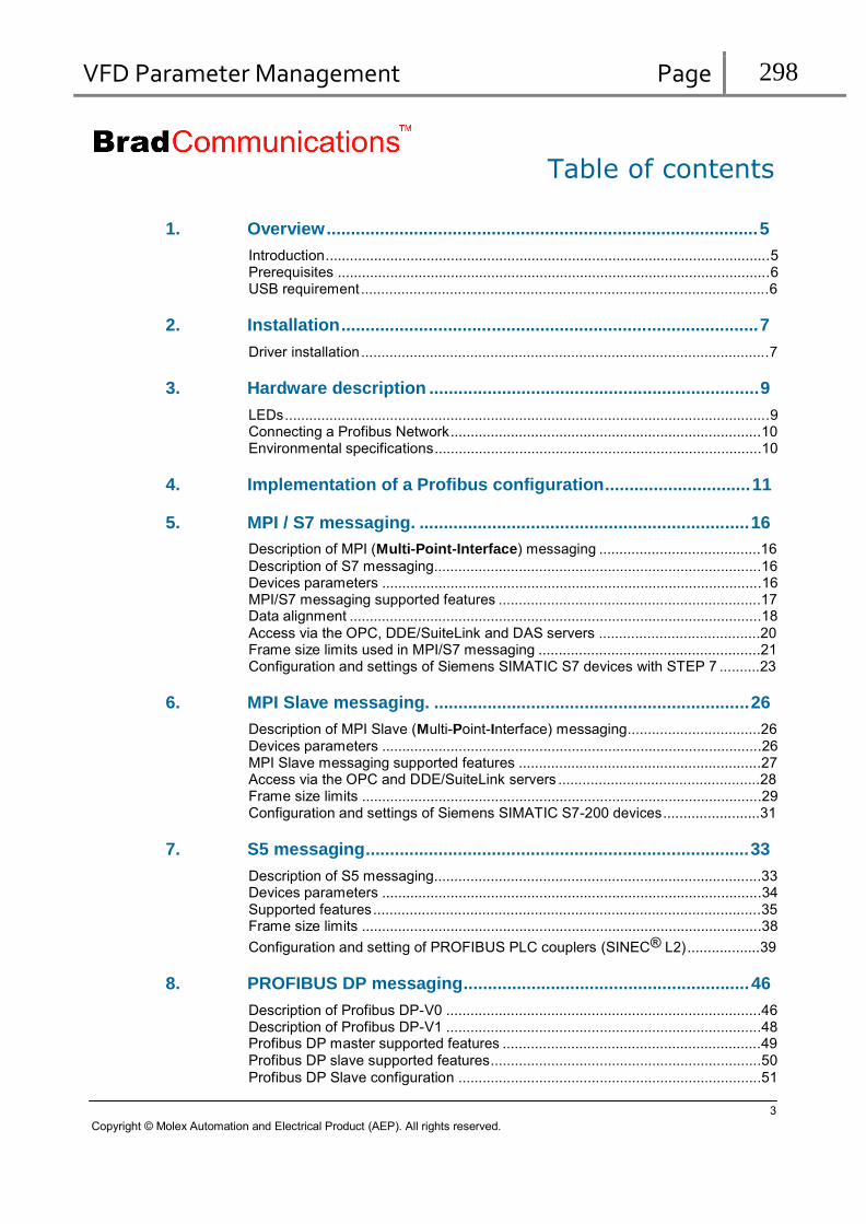
VFD Parameter Management Page 298
Table of contents
1. Overview ......................................................................................... 5
Introduction..............................................................................................................5 Prerequisites ...........................................................................................................6 USB requirement .....................................................................................................6
2. Installation ...................................................................................... 7
Driver installation .....................................................................................................7
3. Hardware description .................................................................... 9
LEDs ........................................................................................................................9 Connecting a Profibus Network.............................................................................10 Environmental specifications.................................................................................10
4. Implementation of a Profibus configuration.............................. 11
5. MPI / S7 messaging. .................................................................... 16
Description of MPI (Multi-Point-Interface) messaging ........................................16
Description of S7 messaging.................................................................................16 Devices parameters ..............................................................................................16 MPI/S7 messaging supported features .................................................................17 Data alignment ......................................................................................................18
Access via the OPC, DDE/SuiteLink and DAS servers ........................................20 Frame size limits used in MPI/S7 messaging .......................................................21 Configuration and settings of Siemens SIMATIC S7 devices with STEP 7 ..........23
6. MPI Slave messaging. ................................................................. 26
Description of MPI Slave (Multi-Point-Interface) messaging.................................26 Devices parameters ..............................................................................................26 MPI Slave messaging supported features ............................................................27 Access via the OPC and DDE/SuiteLink servers ..................................................28 Frame size limits ...................................................................................................29 Configuration and settings of Siemens SIMATIC S7-200 devices ........................31
7. S5 messaging............................................................................... 33
Description of S5 messaging.................................................................................33 Devices parameters ..............................................................................................34 Supported features ................................................................................................35 Frame size limits ...................................................................................................38
Configuration and setting of PROFIBUS PLC couplers (SINEC® L2) ..................39
8. PROFIBUS DP messaging........................................................... 46
Description of Profibus DP-V0 ..............................................................................46 Description of Profibus DP-V1 ..............................................................................48 Profibus DP master supported features ................................................................49 Profibus DP slave supported features...................................................................50
Profibus DP Slave configuration ...........................................................................51
3
Copyright © Molex Automation and Electrical Product (AEP). All rights reserved.

VFD Parameter Management Page 299
Profibus Local DP slave configuration ..................................................................54 Profibus master / slave DPV0 supported variables...............................................57 Frame size limit .....................................................................................................60 Access to Specific Services of Profibus DP messaging (DPV0, DPV1) ...............62 AuWriteReadMsg: .................................................................................................63 AuWriteReadMsg sample......................................................................................75
9. In case of problems ..................................................................... 76
Problems resolution...............................................................................................76 Checking stations on the Profibus network ...........................................................77 Checking the Profibus wiring.................................................................................78 Token management using the Profibus protocol ..................................................79 Profibus timing profiles ..........................................................................................80 Min slave interval...................................................................................................81 Using MPI Socket. .................................................................................................81
10. Returned status ........................................................................... 82
General status .......................................................................................................82 Library specific statuses ........................................................................................82 Statuses relating to the Profibus protocol .............................................................83
11. Annex A: Detect USB capability of your PC .............................. 85
4
Copyright © Molex Automation and Electrical Product (AEP). All rights reserved.

VFD Parameter Management Page 300
1. Overview
Introduction
The Direct-Link™ PC Network interfaces solution DRL-MPI-USB enables your applications to communicate with Siemens PLCs and compatible device using the
S7 protocol (S7-300, S7-400) manufactured by Siemens
MPI protocol (console outlet)
MPI slave protocole (S7-200)
manufactured by Siemens
manufactured by Siemens
The Direct-Link™ PC Network interfaces solution DRL-PFB-USB offers, in addition to the
DRL-MPI-USB solution
Profibus DP-V0 master/slave class 1&2 EN50170
Profibus DP-V1 master class 1&2 EN50170
Simatic S5 messaging manufactured by Siemens
These solutions uses the USB100PFB network adapter compatible with Profibus standard EN
50170 (RS485 with 500 Volts galvanic insulation) at speeds ranging from 9.6 kbps up to 12 Mbps.
Remarks:
These solutions don’t require any external protection system to run.
However, Data servers are an optional feature and required appropriate rights to run. Without these rights, only the DLL library is available. The rights are burned in the USB adapter before shipping. It is however possible to upgrade your rights on site by entering a code supplied by your retailer.
The supplied USB adapter is strongly linked with the ordered solution (DRL_MPI_USB or DRL_PFB_USB) and cannot be used indifferently with both solutions.
Profibus DP-V1 is supported only through DLL access.
See also:
In the documentation:
Protection - Options
5
Copyright © Molex Automation and Electrical Product (AEP). All rights reserved.

VFD Parameter Management Page 301
Prerequisites
The DRL PCNI product is compatible with Windows XP (SP2 recommended) and Windows 2003 Server and Windows Vista.
The DRL PCNI solutions require a specific firmware embedded in the BradCommunications USB100PFB module. As a consequence, DRL-MPI-USB and DRL-PFB-USB solution cannot run with a USB100PFB module delivered with other products (e.g. BradCommunications USB100PFB commDTM module, …)
Only one BradCommunications USB100PFB module must be plugged at the same time
Be sure that the “Power Options Properties” in the “Control panel” of your computer will not suspend the USB port, especially when the usb solution is used on a laptop.
USB requirement
USB host or hub must be compliant with USB 2.0 or 1.1 specifications, High-speed or Full-speed capable, support High-Power Bus-Powered USB device.
Note that USB 2.0 capability is recommended. Indeed, USB 1.1 decreases global performance significantly. To know if your computer has USB 2.0 capable ports, please consult the annex A at the end of this manual
It is recommended to use USB cable supplied along with the product. If longer cable is required, the
USB cable must be certified and capable of USB high-speed.
6
Copyright © Molex Automation and Electrical Product (AEP). All rights reserved.

VFD Parameter Management Page 302
2. Installation
Driver installation
After software installation, first time you will plug the BradCommunications USB100PFB module, the operating system will ask you to install the driver. To do this, just click on button of every window as indicated bellow:
Click on “No, not this time” then on “Next >”
Click on “Install the software automatically (Recommend)” then “Next>”
7
Copyright © Molex Automation and Electrical Product (AEP). All rights reserved.

VFD Parameter Management Page 303
Click on “Continue Anyway”
Click on “Finish”
Now, the solution is ready to use.
8
Copyright © Molex Automation and Electrical Product (AEP). All rights reserved.
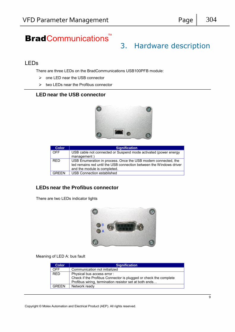
VFD Parameter Management Page 304
3. Hardware description
LEDs
There are three LEDs on the BradCommunications USB100PFB module:
one LED near the USB connector
two LEDs near the Profibus connector
LED near the USB connector
Color Signification OFF USB cable not connected or Suspend mode activated (power energy
management ) RED USB Enumeration in process. Once the USB modem connected, the
led remains red until the USB connection between the Windows driver and the module is completed.
GREEN USB Connection established
LEDs near the Profibus connector
There are two LEDs indicator lights
Meaning of LED A: bus fault
Color Signification
OFF Communication not initialized RED Physical bus access error :
Check if the Profibus Connector is plugged or check the complete Profibus wiring, termination resistor set at both ends…
GREEN Network ready
9
Copyright © Molex Automation and Electrical Product (AEP). All rights reserved.

VFD Parameter Management Page 305
Meaning of LED B: communication status
Color Signification
OFF Communication not initialized RED Layer 2 error or Init error
Check the Profibus: Timing configuration. Profile chosen. Parameter configuration (HSA, TTR, TSLOT,..).
GREEN Communication ready
See also:
In the documentation:
In case of problems
Connecting a Profibus Network
The connection to the PROFIBUS network is made by a female D-Sub 9-pin connector ready to be directly connected to the protocol line.
Environmental specifications
Storage temperature: -20°C to 70°C
Operating temperature: 0°C to 55°C
Humidity: 5% to 95% RH non-condensing
Typical Current Draw for USB connection: 350mA
Power on Profibus connector: 100mA maximum
Galvanic isolation: 500V (UTE C93-703 rules)
10
Copyright © Molex Automation and Electrical Product (AEP). All rights reserved.

VFD Parameter Management Page 306
4. Implementation of a Profibus configuration
Launch the configuration console from the start menu
Select the DRL-MPI-USB or DRL-PFB-USB solution with the menu Description / Add a
board or with the button
Then, configure Profibus master’s parameters. For that, Double-click on the icon
symbolizing the master in the Protocol view.
11
Copyright © Molex Automation and Electrical Product (AEP). All rights reserved.

VFD Parameter Management Page 307
The following dialog box is displayed:
Configure the parameters according to your master configuration. Help for each field is available directly in the Configuration console in the description field.
to configure the remote devices, two configuration methods are possible:
Automatic devices detection:
Your BradCommunications™ USB100PFB module must be already connected to your Profibus network and the station numbers and speeds of your devices are correctly set on your devices.
Choose the “Network detection” tab in the “Resources” area.
12
Copyright © Molex Automation and Electrical Product (AEP). All rights reserved.

VFD Parameter Management Page 308
Activate the network detection with the menu command “Network/Read network
configuration…” or with the button
A minimum configuration is then loaded to initiate the Profibus communication.
The 126 possible station addresses are now scanned and each detected station is inserted in the Network Detection view
All the detected devices can then be added in your configuration with the menu
Network/Insert and replace all or with the button. The devices can also be added individually, by Drag&Drop, from the Network detection tab to the configuration area.
Note To be able to insert a DP device in the configuration, you must own its GSD description file. This GSD file, provided by your device manufacturer, must be inserted previously in the Device Library of the configuration console
When adding a detected device other than Profibus DP in the Protocol view, a dialog box appears enabling you to specify the type of messaging to use :
13
Copyright © Molex Automation and Electrical Product (AEP). All rights reserved.

VFD Parameter Management Page 309
Note All kinds of Profibus stations are always detected (DP, S5, S7,… devices). Stations not supported by the DRL-MPI-USB solution should not be inserted when this solution is used.
See also:
In the documentation:
Implementation Manual
Manual devices configuration:
Your BradCommunications USB100PFB module is not yet linked to your Profibus network, but you know the devices to be configured.
Note To be able to insert a DP device in the configuration, you must own its GSD description file. This GSD file, provided by your device manufacturer, must be inserted previously in the Device Library of the configuration console
Choose the Device library tab in the Resources area.
Select the device to be added.
Drag & Drop the device from the Resources area to the configuration area or use
the insert button
The properties page of the Profibus device is opened automatically, so that you can set the station number and the other parameters. When you validate this page the device is added to the configuration. Repeat the procedure for all the devices to insert. For each device type (DP, S5, S7, etc), you can refer to the corresponding chapter in this manual to find a description of the main required parameters.
14
Copyright © Molex Automation and Electrical Product (AEP). All rights reserved.

VFD Parameter Management Page 310
See also:
In the documentation:
Implementation Manual
In this manual:
Configuration and settings of Siemens SIMATIC S7 devices with STEP 7
Configuration and settings of Siemens SIMATIC S7-200 devices
Configuration and setting of PROFIBUS PLC couplers (SINEC® L2)
Profibus DP Slave configuration
Profibus Local DP slave configuration
15
Copyright © Molex Automation and Electrical Product (AEP). All rights reserved.
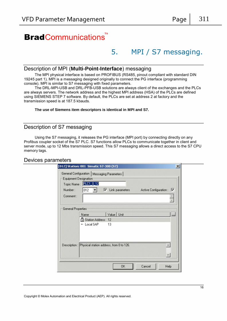
VFD Parameter Management Page 311
5. MPI / S7 messaging.
Description of MPI (Multi-Point-Interface) messaging
The MPI physical interface is based on PROFIBUS (RS485, pinout compliant with standard DIN 19245 part 1). MPI is a messaging designed originally to connect the PG interface (programming console). MPI is similar to S7 messaging with fixed parameters.
The DRL-MPI-USB and DRL-PFB-USB solutions are always client of the exchanges and the PLCs are always servers. The network address and the highest MPI address (HSA) of the PLCs are defined using SIEMENS STEP 7 software. By default, the PLCs are set at address 2 at factory and the transmission speed is at 187.5 kbauds.
The use of Siemens item descriptors is identical in MPI and S7.
Description of S7 messaging
Using the S7 messaging, it releases the PG interface (MPI port) by connecting directly on any Profibus coupler socket of the S7 PLC. S7 functions allow PLCs to communicate together in client and server mode, up to 12 Mbs transmission speed. This S7 messaging allows a direct access to the S7 CPU memory tags.
Devices parameters
16
Copyright © Molex Automation and Electrical Product (AEP). All rights reserved.

VFD Parameter Management Page 312
Parameters Description
Topic Name The name of the topic. This name is used in Data servers (OPC, PCDDE, …) to access the device.
Number Number affected to this device. Comment Describes the device Station Address Profibus station address configured on the device
If the Link parameter box is checked, you cannot change this value which is set identical to
the device number Local SAP Local SAP must be different to Station Address. It must be different for each devices.
The maximum value is 53. So, only 54 devices (SAP 0 to 53) could be accessed. When a new device is inserted in the configuration, the local SAP is automatically set to the station address + 1 (only if the station address is less than 52)
Link parameters Station Address is automatically set according the Number parameter. Active Configuration Activate the device configuration in the applicom
® interface: used to delete a device from
the applicom®
interface while keeping its configuration in the console.
Note
Not all parameters are described in this documentation. For more information on each parameter, refer to description field in the configuration console.
MPI/S7 messaging supported features The variables and functions available via the MPI/S7 messaging are listed in the table below. The address of the variable accessed must be in some cases calculated by referring to the
Addressing column in the table.
Variable
S7-300 S7-400 Addressing Exchange type PLC function
(library/DLL access) My.z DBx.DBXy.z
y*8+z x*524288+y*8+z
Read bits Write bit
READPACKBIT WRITEPACKBIT
Ey.z y*8+z Read input bits READPACKIBIT Ay.z y*8+z Read output bits
Write output bits READPACKQBIT WRITEPACKQBIT
MBy DBx.DBBy
y x*65536+v
Read bytes Write bytes
READPACKBYTE,READBYTE WRITEPACKBYTE,WRITEBYTE
EBy y Read input bytes READPACKIBYTE,READIBYTE ABy y Read output bytes
Write output bytes READPACKQBYTE,READQBYTE WRITEPACKQBYTE,WRITEQBYTE
MWy DBx.DBWy
y x*65536+y
Read words Write words
READWORD WRITEWORD
Ewy y Read input words READIWORD Awy y Read output words
Write output words READQWORD WRITEQWORD
MDy DBx.DBDy
y x*65536+y
Read double words Write double words
READDWORD WRITEDWORD
MDyF DBx.DBDyF
y x*65536+y
Read floating words Write floating words
READFWORD WRITEFWORD
Tn n Read timers Write timers
READTIMER WRITETIMER
Zn n Read counters Write counters
READCOUNTER WRITECOUNTER
x: DB number y: Byte number z: Number of the bit in the byte (0 to 7).
n : No. of the timer or of the counter (0 to 99)
17
Copyright © Molex Automation and Electrical Product (AEP). All rights reserved.

VFD Parameter Management Page 313
Addressing limits:
Each DB variable can be addressed from byte 0 to byte 65535. For the DB bits, only DBs numbered from 1 to 8191 can be addressed. For the bytes, words, double words and floating words, only DBs from 1 to 32767 can be
addressed.
Remarks:
The PROFIBUS S7 communication is currently validated on couplers CP 342-5 and CP 443-5.
Only the current value (CV) of the timers and counters can be accessed (read and write).
Data alignment
The variables of PLCs in the SIEMENS S7 range are byte-ordered both in memento and DB areas.
By default, any read request of words, double words or floating words will return an arry of consecutive data in memory. So,
if you read two words, starting a word MW1, the word MW1 and MW3 will be returned (build respectively with bytes MB1-MB2 and MB3-MB4)
if you read two double words, starting a word MD2, the double words MD2 and MD6 will be returned (build respectively with bytes MB2 to MB5 MB2 and MB6 to MB9)
In order to simplify your application’s design and also to optimize communication when OPC or
DDE servers are used, our recommendation is o leave the default options and to always use even addresses for word data ( MW0, MW2,…) to always use addresses multiple from 4 for double word and floating data (MD0, MD4,…)
However, you may need to access word, double words or floating words whose addresses are
aligned on even or odd addresses. To solve this problem, you can select the required addressing mode in the configuration console (switched in “expert mode”), on byte, word or double word addresses. By making a request to read several words, you can then access a table of words irrespective of their physical addresses.
Example 1: An application wants to read in a request the word MW11 and the word MW13. It will
therefore use a read request from address 11.The response content will take the following form:
if the alignment is on byte address
User array offset S7 mnemonic PLC physical address
0 MW11 11 and 12 1 MW12 11 and 13 2 MW13 13 and 14 3 MW14 14 and 15
if the alignment is on word address
User array offset S7 mnemonic PLC physical address
0 MW11 11 and 12 1 MW13 13 and 14 2 MW15 15 and 16 3 MW17 17 and 18
18
Copyright © Molex Automation and Electrical Product (AEP). All rights reserved.

VFD Parameter Management Page 314
Obviously, this addressing principle cannot be applied to writing several variables in a request. Writing 2 words from address 11
User array offset S7 mnemonic PLC physical address
0 MW11 11 and 12 1 MW13 13 and 14
Example 2: An application wants to read in a request the double words MD10 and t MD16. It will
therefore use a read request from address 10.The response content will take the following form:
if the alignment is on byte address
User array offset S7 mnemonic PLC physical address
0 MD10 from 10 to 13 1 MD11 from 11 to 14 2 MD12 from 12 to 15 3 MD13 from 13 to 16 4 MD14 from 14 to 17 5 MD15 from 15 to 18 6 MD16 from 16 to 19
if the alignment is on word address
User array offset S7 mnemonic PLC physical address
0 MD10 from 10 to 13 1 MD12 from 12 to 15 2 MD14 from 14 to 17 3 MD16 from 16 to 19 4 MD18 from 18 to 21 5 MD20 from 20 to 23 6 MD22 from 22 to 25
if the alignment is on double word address
User array offset S7 mnemonic PLC physical address
0 MD10 from 10 to 13 1 MD14 from 14 to 17 2 MD18 from 18 to 21 3 MD22 from 22 to 25 4 MD26 from 26 to 29 5 MD30 from 30 to 33 6 MD34 from 34 to 37
Writing 3 double words from address 10.
User array offset S7 mnemonic PLC physical address
0 MW10 from 10 to 13 1 MW14 from 14 to 17 2 MW18 from 18 to 21
19
Copyright © Molex Automation and Electrical Product (AEP). All rights reserved.
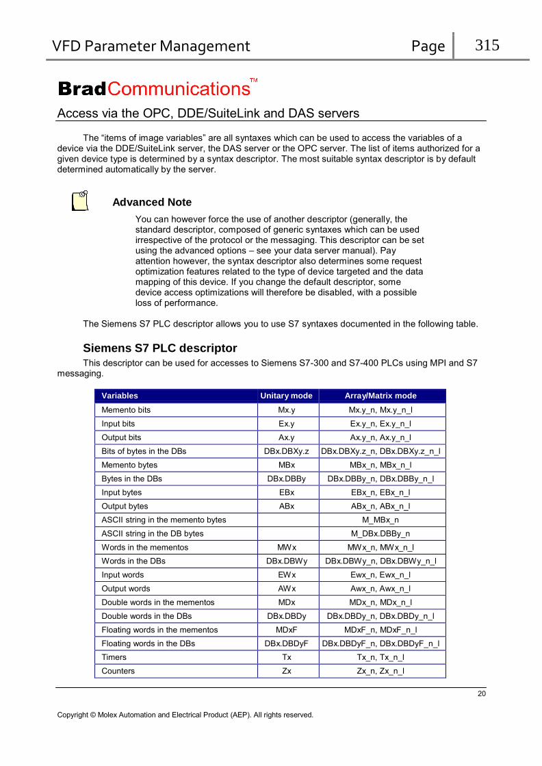
VFD Parameter Management Page 315
Access via the OPC, DDE/SuiteLink and DAS servers
The “items of image variables” are all syntaxes which can be used to access the variables of a device via the DDE/SuiteLink server, the DAS server or the OPC server. The list of items authorized for a given device type is determined by a syntax descriptor. The most suitable syntax descriptor is by default determined automatically by the server.
Advanced Note
You can however force the use of another descriptor (generally, the standard descriptor, composed of generic syntaxes which can be used irrespective of the protocol or the messaging. This descriptor can be set using the advanced options – see your data server manual). Pay attention however, the syntax descriptor also determines some request optimization features related to the type of device targeted and the data mapping of this device. If you change the default descriptor, some device access optimizations will therefore be disabled, with a possible loss of performance.
The Siemens S7 PLC descriptor allows you to use S7 syntaxes documented in the following table.
Siemens S7 PLC descriptor
This descriptor can be used for accesses to Siemens S7-300 and S7-400 PLCs using MPI and S7 messaging.
Variables Unitary mode Array/Matrix mode
Memento bits Mx.y Mx.y_n, Mx.y_n_l
Input bits Ex.y Ex.y_n, Ex.y_n_l
Output bits Ax.y Ax.y_n, Ax.y_n_l
Bits of bytes in the DBs DBx.DBXy.z DBx.DBXy.z_n, DBx.DBXy.z_n_l
Memento bytes MBx MBx_n, MBx_n_l
Bytes in the DBs DBx.DBBy DBx.DBBy_n, DBx.DBBy_n_l
Input bytes EBx EBx_n, EBx_n_l
Output bytes ABx ABx_n, ABx_n_l
ASCII string in the memento bytes M_MBx_n
ASCII string in the DB bytes M_DBx.DBBy_n
Words in the mementos MWx MWx_n, MWx_n_l
Words in the DBs DBx.DBWy DBx.DBWy_n, DBx.DBWy_n_l
Input words EWx Ewx_n, Ewx_n_l
Output words AWx Awx_n, Awx_n_l
Double words in the mementos MDx MDx_n, MDx_n_l
Double words in the DBs DBx.DBDy DBx.DBDy_n, DBx.DBDy_n_l
Floating words in the mementos MDxF MDxF_n, MDxF_n_l
Floating words in the DBs DBx.DBDyF DBx.DBDyF_n, DBx.DBDyF_n_l
Timers Tx Tx_n, Tx_n_l
Counters Zx Zx_n, Zx_n_l
20
Copyright © Molex Automation and Electrical Product (AEP). All rights reserved.

VFD Parameter Management Page 316
area Size/nb mementos 65536 bytes 0 <= x <= 65535 0 <= y <= 7 DB (32767 areas)
65536 bytes 1 <= x <= 32767* 0 <= y <= 65535 0 <= z <= 7 *If z, then: 1 <= x <= 8191
inputs 65536 bytes 0 <= x <= 65535 0 <= y <= 7 Outputs 65536 bytes 0 <= x <= 65535 0 <= y <= 7 Timers 255 0 <= x <= 255 Counters 255 0 <= x <= 255
Warning Use of String, array and Matrix modes requires some precautions due to data alignment configuration. For an alignment on byte addresses when reading 16-bit words or an alignment on byte or word addresses when reading 32-bit words, the write continues to use word addressing for the 16-bit words and double words for the 32-bit words. With array and matrix mode, an item symbolizing for example a word array does not designate the same variables in write as in read. Consequently, array and matrix mode can only be used in read.
Note
The limit values for parameters n and l depend on the protocol. With PCDDE, however, they can never exceed 128 for the bits and the bytes, 64 for the words, 32 for the double words and the floating words.
See also:
In this manual:
Data alignment
Frame size limits used in MPI/S7 messaging
Maximum number of variables per read exchange
Object Max. quantity in read
Alignment Byte Word Double word Bit 1600 Byte 200 Word 128 100 Double word, floating word 64 64 50 Timer/Counter 100
21
Copyright © Molex Automation and Electrical Product (AEP). All rights reserved.

VFD Parameter Management Page 317
Notes
With the OPC, DAS or DDE/SuiteLink data servers, If you use the default syntax descriptor (Siemens S7 PLC descriptor), the server will make the optimizations for read access:
All the unitary data will be accessed by reading bytes (so 200 bytes max by frame)
Others limitations applies only in case of arrays or strings.
With the OPC, DAS or DDE/SuiteLink data servers , the number indicated for read frames corresponds to the maximum (imposed by the server and/or the protocol) number of points which can be grouped during the dynamic frame optimization carried out by the server. However, this number may be reduced to adapt to a particular device, by configuring the frame lengths in the topic.
See also:
In the documentation:
Implementation: Topic configuration
Maximum number of variables per write exchange
Object PCDDE DLL/OPC/DAS
Bit 1 12 Byte 1 200 Word 1 100 Double word, floating word 1 50 Timer/Counter 1 100
Notes
With PCDDE, each variable writing results in the creation of a frame.
See also:
In the documentation:
Software interfaces: OPC Server: Optimization of synchronous and asynchronous requests
22
Copyright © Molex Automation and Electrical Product (AEP). All rights reserved.

VFD Parameter Management Page 318
Configuration and settings of Siemens SIMATIC S7 devices with STEP 7 Configuration is carried out with Step7 software supplied by SIEMENS. For further information,
refer to SIEMENS documentation.
In the following example,
the solution is client of a SIMATIC S7_400 PLC.
CPU slot = 3
You must first create a project in the environment.
Then, declare the hardware configuration of your PLC. You will need to declare: 1 Rack 1 Power supply 1 CPU (note the slot number for the server device configuration) 1 Coupler PROFIBUS CP443-5.
23
Copyright © Molex Automation and Electrical Product (AEP). All rights reserved.

VFD Parameter Management Page 319
Now click on the line corresponding to the coupler to choose its Profibus address.
Click on “PROFIBUS”
24
Copyright © Molex Automation and Electrical Product (AEP). All rights reserved.

VFD Parameter Management Page 320
Choose the following network profile
Load the configuration in the PLC in “Stop” mode, then switch into “Run”.
The green indicator lamps of the CPU and the coupler must be lit steady. The coupler is ready to operate and to be connected.
Note
When devices are disconnected from the network, communication
errors may occur (status 54 or 55). To avoid these problems, it is best to choose the customized profile, and adjust the value of Tslot.
25
Copyright © Molex Automation and Electrical Product (AEP). All rights reserved.

VFD Parameter Management Page 321
6. MPI Slave messaging.
Description of MPI Slave (Multi-Point-Interface) messaging
The MPI Slave physical interface, only available in DRL PCNI solution, is identical to that of PROFIBUS (RS485, pinout in compliance with standard DIN 19245 part 1). The transmission speed goes from 9600 bits/s to 12 Mbits/s.
The DRL PCNI solution, which is always master, allows to communicate with SIEMENS PLCs of the S7-200 family which are always slaves.
The network address, the transmission speed and the highest address of each PLC are defined by using SIEMENS “STEP 7-Micro Win32” software.
In MPI Slave, the used messaging is the S7 messaging embedded in DPV1 Class 2 exchanges.
Devices parameters
26
Copyright © Molex Automation and Electrical Product (AEP). All rights reserved.
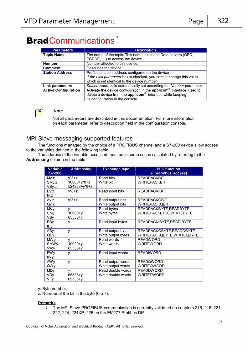
VFD Parameter Management Page 322
Parameters Description Topic Name The name of the topic. This name is used in Data servers (OPC,
PCDDE, …) to access the device. Number Number affected to this device. Comment Describes the device Station Address Profibus station address configured on the device
If the Link parameter box is checked, you cannot change this value
which is set identical to the device number Link parameters Station Address is automatically set according the Number parameter. Active Configuration Activate the device configuration in the applicom
® interface: used to
delete a device from the applicom®
interface while keeping
its configuration in the console.
Note
Not all parameters are described in this documentation. For more information on each parameter, refer to description field in the configuration console.
MPI Slave messaging supported features The functions managed by the choice of a PROFIBUS channel and a S7-200 device allow access
to the variables defined in the following table. The address of the variable accessed must be in some cases calculated by referring to the
Addressing column in the table.
Variable S7-200
Addressing Exchange type PLC function (library/DLL access)
My.z SMy.z VBy.z
y*8+z 10000+y*8+z 524288+y*8+z
Read bits Write bit
READPACKBIT WRITEPACKBIT
Ey.z Iy.z
y*8+z Read input bits READPACKIBIT
Ay.z Qy.z
y*8+z Read output bits Write output bits
READPACKQBIT WRITEPACKQBIT
MVy SMy VBy
y 10000+y 65536+y
Read bytes Write bytes
READPACKBYTE,READBYTE WRITEPACKBYTE,WRITEBYTE
EBy IBy
y Read input bytes READPACKIBYTE,READIBYTE
ABy QBy
y Read output bytes Write output bytes
READPACKQBYTE,READQBYTE WRITEPACKQBYTE,WRITEQBYTE
MWy SMWy VWy
y 10000+y 65536+y
Read words Write words
READWORD WRITEWORD
EWy IWy
y Read input words READIWORD
AWy QWy
y Read output words Write output words
READQWORD WRITEQWORD
MDy
VDy VFy
y
65536+y 65536+y
Read double words
Write double words READDWORD WRITEDWORD
y: Byte number. z: Number of the bit in the byte (0 à 7).
Remarks:
The MPI Slave PROFIBUS communication is currently validated on couplers 215, 216, 221,
222, 224, 224XP, 226 on the EM277 Profibus DP
27
Copyright © Molex Automation and Electrical Product (AEP). All rights reserved.
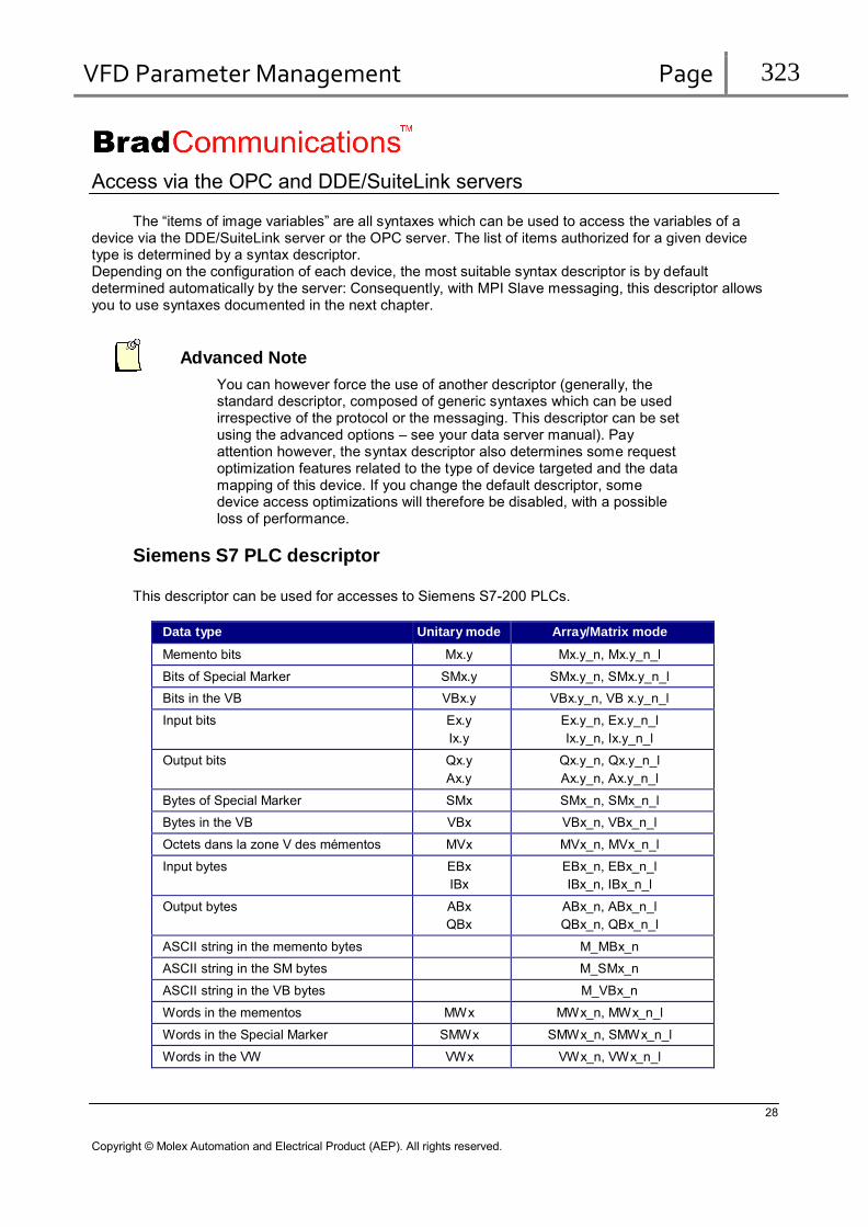
VFD Parameter Management Page 323
Access via the OPC and DDE/SuiteLink servers
The “items of image variables” are all syntaxes which can be used to access the variables of a device via the DDE/SuiteLink server or the OPC server. The list of items authorized for a given device type is determined by a syntax descriptor. Depending on the configuration of each device, the most suitable syntax descriptor is by default determined automatically by the server: Consequently, with MPI Slave messaging, this descriptor allows you to use syntaxes documented in the next chapter.
Advanced Note
You can however force the use of another descriptor (generally, the standard descriptor, composed of generic syntaxes which can be used irrespective of the protocol or the messaging. This descriptor can be set using the advanced options – see your data server manual). Pay attention however, the syntax descriptor also determines some request optimization features related to the type of device targeted and the data mapping of this device. If you change the default descriptor, some device access optimizations will therefore be disabled, with a possible loss of performance.
Siemens S7 PLC descriptor
This descriptor can be used for accesses to Siemens S7-200 PLCs.
Data type Unitary mode Array/Matrix mode
Memento bits Mx.y Mx.y_n, Mx.y_n_l
Bits of Special Marker SMx.y SMx.y_n, SMx.y_n_l
Bits in the VB VBx.y VBx.y_n, VB x.y_n_l
Input bits Ex.y
Ix.y Ex.y_n, Ex.y_n_l
Ix.y_n, Ix.y_n_l
Output bits Qx.y
Ax.y Qx.y_n, Qx.y_n_l
Ax.y_n, Ax.y_n_l
Bytes of Special Marker SMx SMx_n, SMx_n_l
Bytes in the VB VBx VBx_n, VBx_n_l
Octets dans la zone V des mémentos MVx MVx_n, MVx_n_l
Input bytes EBx
IBx EBx_n, EBx_n_l
IBx_n, IBx_n_l
Output bytes ABx
QBx ABx_n, ABx_n_l
QBx_n, QBx_n_l
ASCII string in the memento bytes M_MBx_n
ASCII string in the SM bytes M_SMx_n
ASCII string in the VB bytes M_VBx_n
Words in the mementos MWx MWx_n, MWx_n_l
Words in the Special Marker SMWx SMWx_n, SMWx_n_l
Words in the VW VWx VWx_n, VWx_n_l
28
Copyright © Molex Automation and Electrical Product (AEP). All rights reserved.

VFD Parameter Management Page 324
Input words IWx
EWx IWx_n, IWx_n_l
EWx_n, EWx_n_l
Output words QWx
AWx QWx_n, QWx_n_l
AWx_n, AWx_n_l
Double words in the mementos MDx MDx_n, MDx_n_l
Double words VDx VDx_n, VDx_n_l
Floating words VFx VFx_n, VFx_n_l
area Size/nb mementos 65536 bytes 0 <= x <= 65535 0 <= y <= 7 Inputs 65536 bytes 0 <= x <= 65535 0 <= y <= 7 Outputs 65536 bytes 0 <= x <= 65535 0 <= y <= 7
Warning Use of String, array and Matrix modes requires some precautions due to data alignment configuration. For an alignment on byte addresses when reading 16-bit words or an alignment on byte or word addresses when reading 32-bit words, the write continues to use word addressing for the 16-bit words and double words for the 32-bit words. With array and matrix mode, an item symbolizing for example a word array does not designate the same variables in write as in read. Consequently, array and matrix mode can only be used in read.
Note
The limit values for parameters n and l depend on the protocol. With PCDDE, however, they can never exceed 128 for the bits and the bytes, 64 for the words, 32 for the double words and the floating words.
Frame size limits
Maximum number of variables per read exchange
Object Max. quantity in read
Alignment Byte Word Double word Bit 608 Byte 76 Word 38 38 Double word, floating word 19 19 19
29
Copyright © Molex Automation and Electrical Product (AEP). All rights reserved.

VFD Parameter Management Page 325
Notes
With the OPC, DAS or DDE/SuiteLink data servers, If you use the default syntax descriptor (Siemens S7 PLC descriptor), the server will make the optimizations for read access:
All the unitary data will be accessed by reading bytes (so 76 bytes max by frame)
Others limitations applies only in case of arrays or strings.
With the OPC, DAS or DDE/SuiteLink data servers, the number indicated for read frames corresponds to the maximum (imposed by the server and/or the protocol) number of points which can be grouped during the dynamic frame optimization carried out by the server. However, this number may be reduced to adapt to a particular device, by configuring the frame lengths in the topic.
See also:
In the documentation:
Implementation: Topic configuration
Maximum number of variables per write exchange
Object PCDDE DLL/OPC/DAS
Bit 1 5 Byte 1 76 Word 1 38 Double word, floating word 1 19
Notes
With PCDDE, each variable writing results in the creation of a frame.
See also:
In the documentation:
Software interfaces: OPC Server: Optimization of synchronous and asynchronous requests
30
Copyright © Molex Automation and Electrical Product (AEP). All rights reserved.

VFD Parameter Management Page 326
Configuration and settings of Siemens SIMATIC S7-200 devices
Description
In this example, the solution is client of a SIMATIC S7-200 PLC
PLC configuration with STEP 7-Micro Win32
Configuration is carried out with Step7-Micro Win32 software supplied by SIEMENS. For further
information, refer to SIEMENS documentation.
Set the communication interface
First, set the communication interface with the PLC (Interface PG/PC): If the serial port of the computer is used with a RS232/PPI converter:
1. In the configuration panel, clic on “Set PG/PC Interface”. 2. In the “Access Point of the Application” list, choose “Micro/WIN => PC/PPI cable(PPI)”. 3. Then in the list “Interface Parameter Assignement Used”, choose “PC/PPI cable (PPI)”. 4. The button “Properties…” allows to check the serial port parameters.
Step 7-Micro/Win is then ready to communicate with the S7-200 PLC.
Use of Step 7-Micro/Win
At the first start of Step 7-Micro/Win, create a new project. Show the following window by clicking the button “System Block”:
Set the interfaces 0 and 1 according to S7-200 PLC used and according to the characteristics of the Profibus Network.
31
Copyright © Molex Automation and Electrical Product (AEP). All rights reserved.
VFD Parameter Management Page 327
Then load the configuration in the PLC. The green indicator lamps of the CPU and the coupler
must be lit steady. The coupler is ready to operate and to be connected, after running the launch file
“pcinit”.
32
Copyright © Molex Automation and Electrical Product (AEP). All rights reserved.

VFD Parameter Management Page 328
S 5 00: Read 01: Write
(2 bits)
Object type (6 bits)
DB No.
(If type 01 otherwise 0)
Address of first object
Number of objects Message counter
7. S5 messaging
Description of S5 messaging
The S5 messaging developed by Siemens France uses the SDA services. This access is materialized by a program section (supplied by us in the product) to be integrated in the Siemens PLCs. This program consists of an FB(FB100). It is validated on the CPUs 928, 928B, 942, 943, 943B, 944, 944B, 945, 946, 947, 948, 948B and on the 95U. The solution is always client of the exchanges and the PLCs are always servers. S5 messaging is carried in the “Data” part of a PROFIBUS telegram. Management of this protocol is completely transparent for product users.
A description of this protocol is provided below for information.
Byte 0 & 1
Byte 2 & 3
Byte 4 & 5
Byte 6 & 7
Object type:
Type Step5 object Description
01 DB Data block 02 M Internal variable (memento) 03 E Input 04 A Output 08 SY Internal variable (SMerker) 10 DX Extended data block
33
Copyright © Molex Automation and Electrical Product (AEP). All rights reserved.
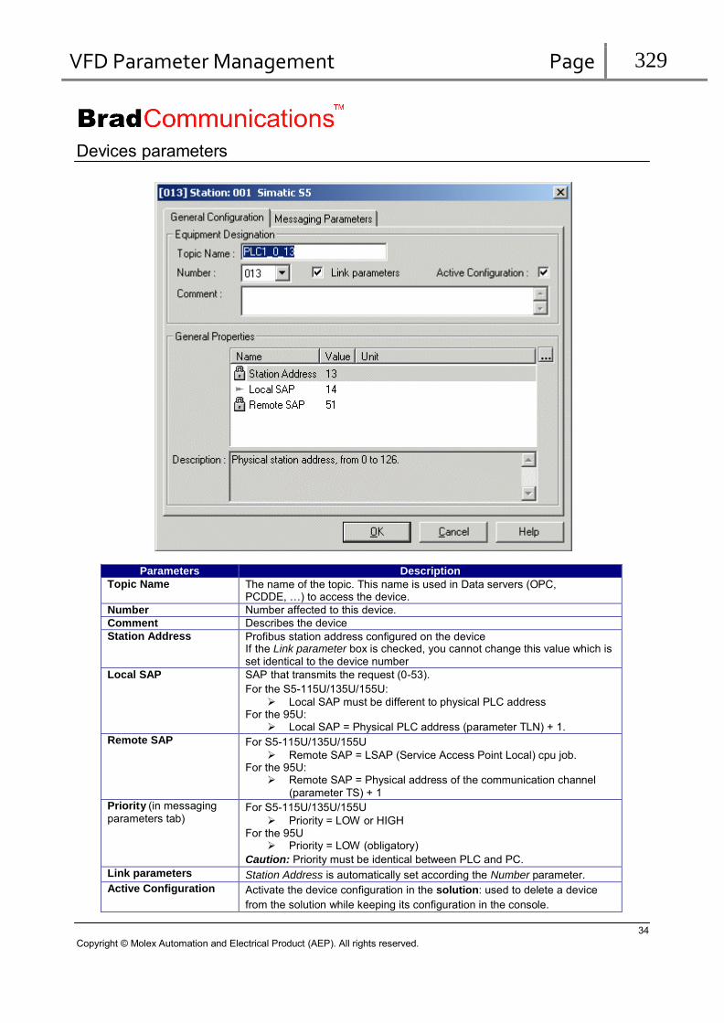
VFD Parameter Management Page 329
Devices parameters
Parameters Description Topic Name The name of the topic. This name is used in Data servers (OPC,
PCDDE, …) to access the device. Number Number affected to this device. Comment Describes the device Station Address Profibus station address configured on the device
If the Link parameter box is checked, you cannot change this value which is set identical to the device number
Local SAP SAP that transmits the request (0-53).
For the S5-115U/135U/155U:
Local SAP must be different to physical PLC address For the 95U:
Local SAP = Physical PLC address (parameter TLN) + 1. Remote SAP For S5-115U/135U/155U
Remote SAP = LSAP (Service Access Point Local) cpu job. For the 95U:
Remote SAP = Physical address of the communication channel
(parameter TS) + 1 Priority (in messaging
parameters tab) For S5-115U/135U/155U
Priority = LOW or HIGH For the 95U
Priority = LOW (obligatory)
Caution: Priority must be identical between PLC and PC. Link parameters Station Address is automatically set according the Number parameter. Active Configuration Activate the device configuration in the solution: used to delete a device
from the solution while keeping its configuration in the console.
34
Copyright © Molex Automation and Electrical Product (AEP). All rights reserved.

VFD Parameter Management Page 330
Note
Not all parameters are described in this documentation. For more information on each parameter, refer to description field in the configuration console.
Supported features The functions managed by the choice of a PROFIBUS Master channel allow access to the variables defined in the following table. The address of the variable accessed must be in some cases calculated by referring to the “Addressing”
column in the table.
Variable
Siemens PLC Addressing
(addr) Exchange type
(cyclic mode) PLC functions
M v.w
S v.w
DB x D y.z
DX x D y.z
v*8+w
v*8+w +2097152
x*4096+y*16+z
x*4096+y*16+z +1048576
Read bits
Write bits READPACKBIT
WRITEPACKBIT
MB v
SY v v
v + 131072 Read bytes
Write bytes READBYTE
WRITEBYTE MB v
SY v v
v + 131072 Read packed bytes
Write packed bytes READPACKBYTE
WRITEPACKBYTE MW v
SW v
DB x DW y
DX x DW y
v
v + 131072
x*256+y
x*256+y + 65536
Read words
Write words READWORD
WRITEWORD
MD v
SD v
DB x DD y
DX x DD y
v
v + 131072
x*256+y
x*256+y + 65536
Read double words
Write double words READDWORD
WRITEDWORD
MD v KG
SDvKG
DBxDDyKG
DXxDDyKG
v
v + 131072
x*256+y
x*256+y + 65536
Read floating words
Write floating words READFWORD
WRITEFWORD
E v,w v*8+w Read input bits READPACKIBIT EB v v Read input bytes READIBYTE EB v v Read packed input bytes READPACKIBYTE EW v v Read input words READIWORD A v.w v*8+w Read output bits
Write output bits READPACKQBIT
WRITEPACKQBIT AB v v Read output bytes
Write output bytes READQBYTE
WRITEQBYTE AB v v Read packed output bytes
Write packed output bytes READPACKQBYTE
WRITEPACKQBYTE AW v v Read output words
Write output words READQWORD
WRITEQWORD TB n n Read timers
Write timers READTIMER
WRITETIMER ZB n n Read counters
Write counters READCOUNTER
WRITECOUNTER
V: Byte No. y: No. of the word in the DB or in the DX (0 to 255) W: No. of the bit in the byte (0 to 7) z: No. of the bit in the word (0 to 15)
x: No. of the DB (1 to 255) or of the DX (0 to 255) n: No. of the timer or of the counter (0 to 255)
35
Copyright © Molex Automation and Electrical Product (AEP). All rights reserved.

VFD Parameter Management Page 331
Caution:
The SMerkers and the DX cannot be accessed with all Siemens CPUs.
For access to words in the mementos or in the SMerkers, to input words and output words,
these words are accessed in a byte area, word 1 being composed of bytes 1 and 2, word 2 of bytes 2 and 3, etc. The words therefore overlap on each other.
For access to double words and floating words in the mementos or in the SMerkers, these
variables are accessed in a byte area, double word 1 being composed of bytes 1, 2, 3 and 4, double word 2 of bytes 2, 3, 4 and 5,… The variables therefore overlap on each other.
Descriptor for Siemens series 5 PLCs, German (D) and French syntax
This descriptor can only be used in the event of accesses to Siemens Simatic S5 PLCs in S5 messaging,
Unitary mode Array/Matrix mode
Memento bits Mx.y Mx.y_n, Mx.y_n_l
Smerker bits (internal bytes) Sx.y Sx.y_n, Sx.y_n_l
Input bits Ex.y Ex.y_n, Ex.y_n_l
Output bits Ax.y Ax.y_n, Ax.y_n_l
Bits of words in the DBs DBxDy.z DBxDy.z_n, DBxDy.z_n_l
Bits of words in the DXs DXxDy.z DXxDy.z_n, DXxDy.z_n_l
Memento bytes MBx MBx_n, MBx_n_l
Internal bytes (SMerkers) SYx SYx_n, SYx_n_l
Input bytes EBx EBx_n, EBx_n_l
Output bytes ABx ABx_n, ABx_n_l
ASCII string in the memento bytes M_MBx_n
ASCII string in the internal bytes (SMerkers) M_SYx_n
Words in the mementos MWx MWx_n, MWx_n_l
Words in the Smerkers (internal bytes) SWx SWx_n, SWx_n_l
Input words EWx EWx_n, EWx_n_l
Output words AWx AWx_n, AWx_n_l
Words in the DBs DBxDWy DBxDWy_n, DBxDWy_n_l
Words in the DXs DXxDWy DXxDWy_n, DXxDWy_n_l
Right byte of a word in the DBs DBxDRy
Left byte of a word in the DBs DBxDLy
Right byte of a word in the DXs DXxDRy
Left byte of a word in the DXs DXxDLy
ASCII string in the DB words M_DBxDWy_n
ASCII string in the DX words M_DXxDWy_n
Double words in the memento bytes MDx MDx_n, MDx_n_l
Double words in the Smerkers (internal bytes) SDx SDx_n, SDx_n_l
Floating words in the memento bytes MDxKG
Floating words in the Smerkers (internal bytes) SDxKG
Double words in the DBs DBxDDy DBxDDy_n, DBxDDy_n_l
Double words in the DXs DXxDDy DXxDDy_n, DXxDDy_n_l
36
Copyright © Molex Automation and Electrical Product (AEP). All rights reserved.

VFD Parameter Management Page 332
Floating words in the DBs DBxDDyKG
Floating words in the DXs DXxDDyKG
Timers TBx TBx_n, TBx_n_l
Counters ZBx ZBx_n, ZBx_n_l
area Size/nb
mementos 256 bytes 0 <= x <= 255 0 <= y <= 7
SMerkers 4096 bytes 0 <= x <= 4095 0 <= y <= 7
DB (256 areas) 256 words 0 <= x <= 255 0 <= y <= 255 0 <= z <= 15
DX (256 areas) 256 words 0 <= x <= 255 0 <= y <= 255 0 <= z <= 15
Inputs 128 bytes 0 <= x <= 127 0 <= y <= 7
Outputs 128 bytes 0 <= x <= 127 0 <= y <= 7
Timers 128 0 <= x <= 255
Counters 128 0 <= x <= 255
Remark:
The limiting values of the parameters n and l depend on the protocol.
Descriptor for Siemens series 5 PLCs, English (GB) syntax
This descriptor can only be used in the event of accesses to Siemens Simatic S5 PLCs in S5 messaging
Unitary mode Array/Matrix mode
Memento bits Fx.y Fx.y_n, Fx.y_n_l
Smerker bits (internal bytes) Sx.y Sx.y_n, Sx.y_n_l
Input bits Ix.y Ix.y_n, Ix.y_n_l
Output bits Qx.y Qx.y_n, Qx.y_n_l
Bits of words in the DBs DBxDy.z DBxDy.z_n, DBxDy.z_n_l
Bits of words in the DXs DXxDy.z DXxDy.z_n, DXxDy.z_n_l
Memento bytes FYx FYx_n, FYx_n_l
Internal bytes (SMerkers) SYx SYx_n, SYx_n_l
Input bytes IBx IBx_n, IBx_n_l
Output bytes QYx QYx_n, QYx_n_l
ASCII string in the memento bytes M_FYx_n
ASCII string in the internal bytes (SMerkers) M_SYx_n
Words in the mementos FWx FWx_n, FWx_n_l
Words in the Smerkers (internal bytes) SWx SWx_n, SWx_n_l
Input words Iwx IWx_n, IWx_n_l
Output words QWx QWx_n, QWx_n_l
Words in the DBs DBxDWy DBxDWy_n, DBxDWy_n_l
Words in the DXs DXxDWy DXxDWy_n, DXxDWy_n_l
Right byte of a word in the DBs DBxDRy
Left byte of a word in the DBs DBxDLy
Right byte of a word in the DXs DXxDRy
Left byte of a word in the DXs DXxDLy
ASCII string in the DB words M_DBxDWy_n
ASCII string in the DX words M_DXxDWy_n
Double words in the memento bytes FDx FDx_n, FDx_n_l
Double words in the Smerkers (internal bytes) SDx SDx_n, SDx_n_l
37
Copyright © Molex Automation and Electrical Product (AEP). All rights reserved.
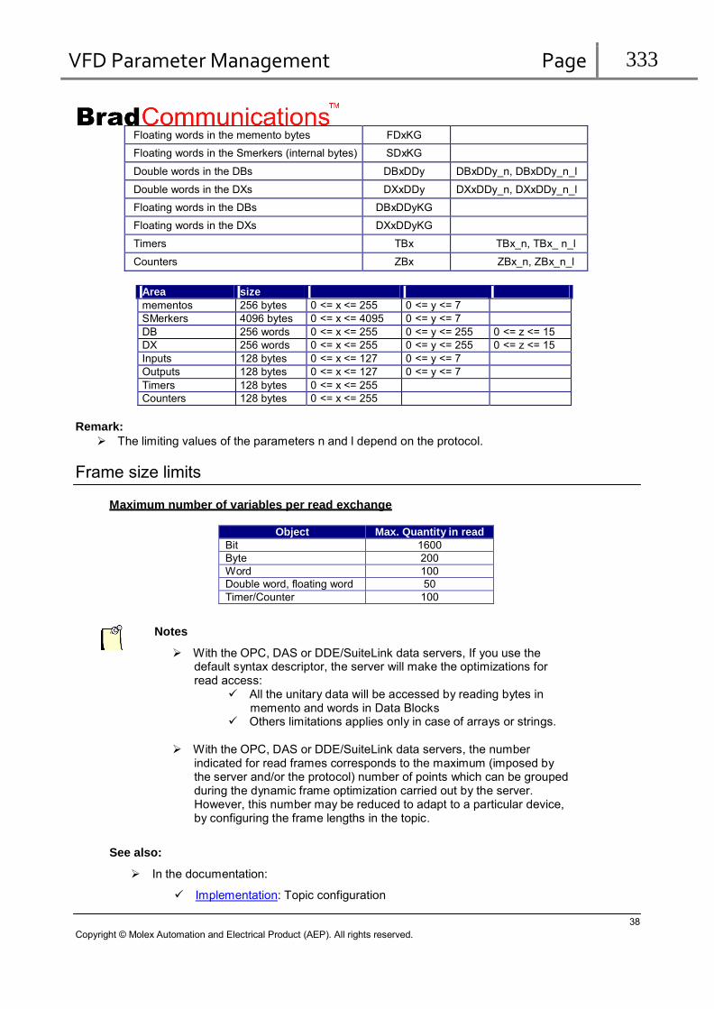
VFD Parameter Management Page 333
Floating words in the memento bytes FDxKG
Floating words in the Smerkers (internal bytes) SDxKG
Double words in the DBs DBxDDy DBxDDy_n, DBxDDy_n_l
Double words in the DXs DXxDDy DXxDDy_n, DXxDDy_n_l
Floating words in the DBs DBxDDyKG
Floating words in the DXs DXxDDyKG
Timers TBx TBx_n, TBx_ n_l
Counters ZBx ZBx_n, ZBx_n_l
Area size mementos 256 bytes 0 <= x <= 255 0 <= y <= 7 SMerkers 4096 bytes 0 <= x <= 4095 0 <= y <= 7 DB 256 words 0 <= x <= 255 0 <= y <= 255 0 <= z <= 15 DX 256 words 0 <= x <= 255 0 <= y <= 255 0 <= z <= 15 Inputs 128 bytes 0 <= x <= 127 0 <= y <= 7 Outputs 128 bytes 0 <= x <= 127 0 <= y <= 7 Timers 128 bytes 0 <= x <= 255 Counters 128 bytes 0 <= x <= 255
Remark:
The limiting values of the parameters n and l depend on the protocol.
Frame size limits
Maximum number of variables per read exchange
Object Max. Quantity in read
Bit 1600 Byte 200 Word 100 Double word, floating word 50 Timer/Counter 100
Notes
With the OPC, DAS or DDE/SuiteLink data servers, If you use the default syntax descriptor, the server will make the optimizations for read access:
All the unitary data will be accessed by reading bytes in memento and words in Data Blocks
Others limitations applies only in case of arrays or strings.
With the OPC, DAS or DDE/SuiteLink data servers, the number
indicated for read frames corresponds to the maximum (imposed by the server and/or the protocol) number of points which can be grouped during the dynamic frame optimization carried out by the server. However, this number may be reduced to adapt to a particular device, by configuring the frame lengths in the topic.
See also:
In the documentation:
Implementation: Topic configuration
38
Copyright © Molex Automation and Electrical Product (AEP). All rights reserved.

VFD Parameter Management Page 334
Maximum number of variables per write exchange
Object PCDDE DLL/OPC/DAS
Bit 1 8 or 16 * Byte 1 200 Word 1 100 Double word, floating word 1 50 Timer / Counter 1 100
Notes
With PCDDE, each variable writing results in the creation of a frame.
Notes
*: A bit write request limited to a maximum of: - 8 bits for a memento or a Smerker with start address modulo 8 - 8 bits for the outputs with start address modulo 8 -16 bits for a DB or a DX with start address modulo 16
Example: You can force on an output board:
8 bits from address 0 7 bits from address 1 etc.
See also:
In the documentation:
Software interfaces: OPC Server: Optimization of synchronous and asynchronous requests
Configuration and setting of PROFIBUS PLC couplers (SINEC® L2)
Connection between the computer and the SIEMENS PLC
The PC is connected to the SINEC L2 bus via the board. A SIEMENS PLC is connected to the
SINEC L2 network by installing a special communication processor, coupler CP 5430 TF or CP 5431
FMS, which is connected directly on the backplane bus of SIMATIC S5 PLCs. The CP can be used with
all S5 systems as of S5 115U and better. There are two physical interfaces on the CPs, one to connect
the SINEC L2 field network and the other to access the coupler configuration and setting. Traffic
management on the L2 network is processed independently by the CPs, so the CPU of the S5 PLC does
not have to perform this task.
Communication between the S5 processor and the communication coupler.
Communication between the PLC processor and the coupler is carried out via a dual port RAM
thereby ensuring very fast exchanges. This data exchange is carried out using communication blocks which are PLC sub-programs partly supplied with the product. The CPUs supported are 95U, 928, 928B, 942, 943, 943B, 944, 944B, 945, 946, 947, 948, 948B.
These sub-programs are stored in directory install\simatic\simatic.s5 on the CD-ROM.
39
Copyright © Molex Automation and Electrical Product (AEP). All rights reserved.
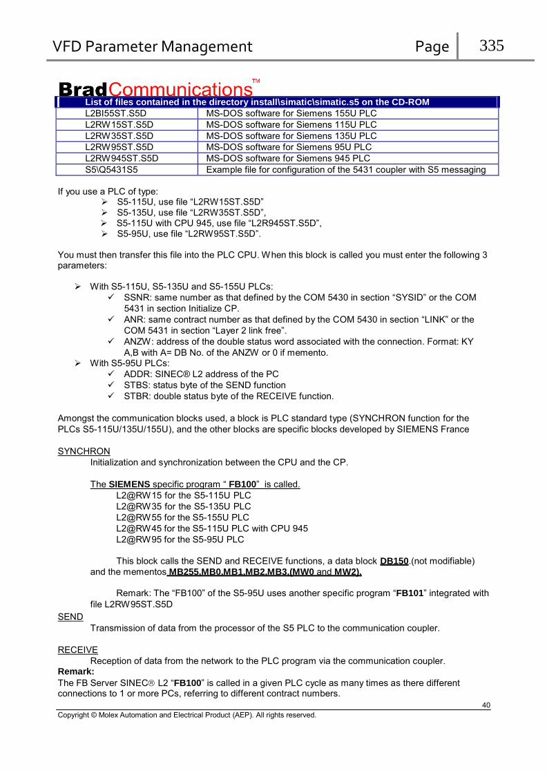
VFD Parameter Management Page 335
List of files contained in the directory install\simatic\simatic.s5 on the CD-ROM L2BI55ST.S5D MS-DOS software for Siemens 155U PLC L2RW15ST.S5D MS-DOS software for Siemens 115U PLC L2RW35ST.S5D MS-DOS software for Siemens 135U PLC L2RW95ST.S5D MS-DOS software for Siemens 95U PLC L2RW945ST.S5D MS-DOS software for Siemens 945 PLC S5\Q5431S5 Example file for configuration of the 5431 coupler with S5 messaging
If you use a PLC of type: S5-115U, use file “L2RW15ST.S5D” S5-135U, use file “L2RW35ST.S5D”, S5-115U with CPU 945, use file “L2R945ST.S5D”, S5-95U, use file “L2RW95ST.S5D”.
You must then transfer this file into the PLC CPU. When this block is called you must enter the following 3 parameters:
With S5-115U, S5-135U and S5-155U PLCs:
SSNR: same number as that defined by the COM 5430 in section “SYSID” or the COM
5431 in section Initialize CP.
ANR: same contract number as that defined by the COM 5430 in section “LINK” or the
COM 5431 in section “Layer 2 link free”.
ANZW: address of the double status word associated with the connection. Format: KY
A,B with A= DB No. of the ANZW or 0 if memento. With S5-95U PLCs:
ADDR: SINEC® L2 address of the PC
STBS: status byte of the SEND function
STBR: double status byte of the RECEIVE function.
Amongst the communication blocks used, a block is PLC standard type (SYNCHRON function for the
PLCs S5-115U/135U/155U), and the other blocks are specific blocks developed by SIEMENS France
SYNCHRON
Initialization and synchronization between the CPU and the CP.
The SIEMENS specific program “ FB100” is called.
L2@RW15 for the S5-115U PLC
L2@RW35 for the S5-135U PLC
L2@RW55 for the S5-155U PLC
L2@RW45 for the S5-115U PLC with CPU 945
L2@RW95 for the S5-95U PLC
This block calls the SEND and RECEIVE functions, a data block DB150.(not modifiable)
and the mementos MB255,MB0,MB1,MB2,MB3,(MW0 and MW2).
Remark: The “FB100” of the S5-95U uses another specific program “FB101” integrated with
file L2RW95ST.S5D
SEND Transmission of data from the processor of the S5 PLC to the communication coupler.
RECEIVE
Reception of data from the network to the PLC program via the communication coupler. Remark:
The FB Server SINEC L2 “FB100” is called in a given PLC cycle as many times as there different connections to 1 or more PCs, referring to different contract numbers.
40
Copyright © Molex Automation and Electrical Product (AEP). All rights reserved.
VFD Parameter Management Page 336
Example:
The following example shows how these function blocks must be called if you are using a PLC in
the S5-115U family. Note that the number of the function blocks differs from one type of PLC to another.
The SYNCHRON block must be called by the PLC program on each hot or cold restart of the PLC.
OB21 and OB22 (Organization blocks 21 and 22 )
SPA FB 249 ; Call block FB249.
NAME: SYNCHRON ; The console writes the block name. SSNR: KY 0,0 ; Memory area reserved for coupler access.
BLGR: KY 0,0 ; Size of the data area used for CPU<->CP communication.
; 0 = maximum size.
PAFE: MB 255 ; Diagnostic byte.
In block OB1 you must call block FB100. This special block links the SINEC L2 reception request
to the PLC data area.
Example on S5-115U/135U PLC:
OB1
:SPA FB100 ; This block is included in file L2RW15ST.S5D. Caution, this block
; uses the data blocks DB150, TRANSMISSION and RECEPTION.
NAME: L2@RW15
SSNR: KF +0 ; interface number defined by utility COM5430 or COM5431
ANR : KF +150 ; contract number defined by the utility COM 5430 or COM 5431
ANZW: KY 0,0 ; report
Example on S5-95U PLC:
OB1
SPA FB100 ; This block is included in file L2RW95ST.S5D. Caution, this block
; uses the data blocks DB150, TRANSMISSION and RECEPTION.
NAME: L2@RW95 ADDR: KF +1 ;SINEC L2 address of PC=1 STBS: MB150 ; status byte SEND = MB150 STBR: MB151 ;double status byte RECEIVE = MB151 and MB152
41
Copyright © Molex Automation and Electrical Product (AEP). All rights reserved.

VFD Parameter Management Page 337
Configuration of the SIEMENS CP5430 with COM5430
Configuration is carried out with COM5430 software supplied by SIEMENS. When the software is
started and open, you must select F2 to configure each part of the CP5430 board. You must then
configure the system identification. In the section “SYSID” you must complete the SSNR number which is
passed in as parameter when calling the manager block FB100.
To configure the parameters of the SINEC L2 bus, select “INIT”. Now create a logical link with
“LINK”. The following screen is displayed:
The Profibus protocol uses access to layer 2. The service used is SDA (Send Data with
Acknowledge).
Column Description
TYPE To define an access to layer 2, TYPE must be OPEN.(link open) PRIO Access on SINEC L2 can be defined in high or low priority. SSNR You must enter the SSNR (memory page area) (range of values 0 to 3) ANR Configurable as you choose, "job number" is used during direct accesses to layer 2, ANR must be
between 134-186., parameter ANR of the SIEMENS special block (FB100) must be initialized to this value.
SAP SAP (Service Access Point) is an address extension. All frames are received / transmitted by this SAP.
42
Copyright © Molex Automation and Electrical Product (AEP). All rights reserved.

VFD Parameter Management Page 338
Configuration of CP 5430 TF for S5 Messaging
Configuration is carried out with COM 5430 TF software under SINEC NCM supplied by
SIEMENS. When the software is started and open, you must configure each part of the CP 5430 board.
You must configure the system identification “SYSID” via the menu Edit\Init CP. In this section you must
enter the L2 address of the station, the station type (must be Active), the base No-Int, the number of
interfaces (CP5430) and parameters complementary to your project. You must now configure the network
parameters then create a logical link via the menu Edit\Links. Choose Free layer 2 link, the following
screen is displayed:
The Profibus protocol uses access to layer 2. The service used is SDA (Send Data with
Acknowledge).
Parameters Description
Local station address Write protected parameter indicating the address of the station being configured. PRIO Access on SINEC L2 can be defined in high or low priority. SSAP Local Service Access Point is an address extension. All frames are received / transmitted
by this SAP. No_I You must enter the SSNR (memory page area) (range of values 0 to 0.3) No_O Configurable as you choose, “job number” is used during direct accesses to layer 2, No-O
must be between 134-186., parameter ANR of the SIEMENS special block (FB100) must be initialized to this value.
43
Copyright © Molex Automation and Electrical Product (AEP). All rights reserved.
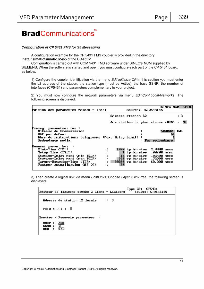
VFD Parameter Management Page 339
Configuration of CP 5431 FMS for S5 Messaging
A configuration example for the CP 5431 FMS coupler is provided in the directory install\simatic\simatic.s5\s5 of the CD-ROM
Configuration is carried out with COM 5431 FMS software under SINEC NCM supplied by
SIEMENS. When the software is started and open, you must configure each part of the CP 5431 board,
as below:
1) Configure the coupler identification via the menu Edit\initialize CP.In this section you must enter the L2 address of the station, the station type (must be Active), the base SSNR, the number of interfaces (CP5431) and parameters complementary to your project.
2) You must now configure the network parameters via menu Edit\Conf.Local-Networks. The following screen is displayed:
3) Then create a logical link via menu Edit\Links. Choose Layer 2 link free, the following screen is displayed:
44
Copyright © Molex Automation and Electrical Product (AEP). All rights reserved.

VFD Parameter Management Page 340
The Profibus protocol uses access to layer 2. The service used is SDA (Send Data with
Acknowledge).
Parameters Description
Local L2 station
address Write protected parameter indicating the address of the station being configured.
PRIO (H/L) Access on SINEC L2 can be defined in high or low priority. SSAP Local Service Access Point is an address extension. All frames are received / transmitted
by this SAP. SSNR You must enter the SSNR (memory page area) (range of values 0 to 0.3) ANR Configurable as you choose, “job number” is used during direct accesses to layer 2, ANR
must be between 134-186., parameter ANR of the SIEMENS special block (FB100) must be initialized to this value.
Configuration of the SINEC® L2 integrated interface of the S5-95U
Configuration is carried out via data block DB1 in section “SL2”. No matter which transmission
mode is selected, you must define certain parameters in this section. To define the various fields, refer to
the manufacturer's documentation (ref. 6ES5-998-8MB31).
Block DB1 in L2RW95ST.S5D (section “SL2”):
156: KC =';# SL2: TLN 2 STA AKT';
168: KC =' BDR 500 HSA 10 TRT ';
180: KC ='30000 SET 1 ST 1000 ';
192: KC ='SDT 1 12 SDT 2 360 SF';
204: KC =' DB6 DW0 EF DB7 DW0 ';
216: KC =' KBS MB62 KBE MB63 ';
228: KC ='STBS 1 MB150 STBR 1 MB15';
240: KC ='1 STBS 3 MB160 STBR 3 MB';
252: KC ='161 ; END ';
Default parameters in file L2RW95ST.S5D:
TLN : 2 ; address of the 95U on the network
STA : AKT ; active station (mandatory)
BDR : 500 kbauds ; transmission speed
HSA : 10 ; highest station address of all active stations
TRT : 30000 ; Target-Rotation-Time
SET : 1 ; Setup-Time (dead time)
ST : 1000 ; Slot-Time (reception time-out)
SDT1 : 12 ; Protocol minimum processing time
SDT2 : 360 ; Protocol maximum processing time
STBS : 1 MB150 : Contract No. and status byte “Transmission”
STBR : 1 MB151 : Contract No. and status bytes “Reception” (2 bytes used)
The contract No. corresponds to parameter ADDR, remote station address (@ PC), passed in on
calling the function block FB100.
For further details on the DB1 parameters, refer to the manufacturer's documentation.
Remarks:
The link type is AGAG.
The priority must be low (Caution! Make sure to define same priority on the PC side),
ADDR contract No. = SINEC L2 address of the PC.
45
Copyright © Molex Automation and Electrical Product (AEP). All rights reserved.

VFD Parameter Management Page 341
8. PROFIBUS DP messaging
Description of Profibus DP-V0
The PROFIBUS DP field bus is based on the European standard EN 50170. PROFIBUS DP telegrams can be used to transfer up to 244 bytes of data per telegram and connect to devices of address from 0 to 126. All data exchanges use the SAPs (Service Access Point). PROFIBUS DP uses SAPs from 54 to 62.
Our solutions include:
the class 1 DP master functionalities for optimized exchange of input/output data and device
diagnostics,
the class 2 DP master functionalities for access to device belonging to other masters and reading
the DP slave input/output configurations,
Multi-master operation, to enable several profibus masters to run on the same network (for example: a class 2 DP master and a class 1 DP master). This operation is based on the token ring. It is a logical ring where each master station passes in a defined order (of increasing address), the token giving the right to transmit or pass its turn.
The information required for device configuration is contained in a file of type XXXXXX.GSD which is
supplied by the manufacturer. It is required to import the GSD file in the device library of the
configuration console.
The format of the GSD file is described in the standard EN 50170, volume 2, PROFIBUS.
46
Copyright © Molex Automation and Electrical Product (AEP). All rights reserved.
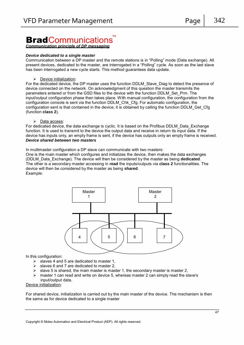
VFD Parameter Management Page 342
Communication principle of DP messaging
Device dedicated to a single master Communication between a DP master and the remote stations is in “Polling” mode (Data exchange). All present devices, dedicated to the master, are interrogated in a “Polling” cycle. As soon as the last slave has been interrogated a new cycle starts. This method guarantees data update.
Device initialization:
For the dedicated device, the DP master uses the function DDLM_Slave_Diag to detect the presence of device connected on the network. On acknowledgment of this question the master transmits the parameters entered or from the GSD files to the device with the function DDLM_Set_Prm. The input/output configuration phase then takes place. With manual configuration, the configuration from the configuration console is sent via the function DDLM_Chk_Cfg. For automatic configuration, the configuration sent is that contained in the device; it is obtained by calling the function DDLM_Get_Cfg (function class 2).
Data access:
For dedicated device, the data exchange is cyclic. It is based on the Profibus DDLM_Data_Exchange function. It is used to transmit to the device the output data and receive in return its input data. If the device has inputs only, an empty frame is sent, if the device has outputs only an empty frame is received. Device shared between two masters
In multimaster configuration a DP slave can communicate with two masters: One is the main master which configures and initializes the device, then makes the data exchanges (DDLM_Data_Exchange). The device will then be considered by the master as being dedicated. The other is a secondary master accessing in read the inputs/outputs via class 2 functionalities. The device will then be considered by the master as being shared.
Example:
Master
1 Master
2
4 5 6 7
In this configuration:
slaves 4 and 5 are dedicated to master 1, slaves 6 and 7 are dedicated to master 2, slave 5 is shared, the main master is master 1, the secondary master is master 2, master 1 can read and write on device 5, whereas master 2 can simply read the slave's
input/output data. Device initialization:
For shared device, initialization is carried out by the main master of the device. The mechanism is then the same as for device dedicated to a single master
47
Copyright © Molex Automation and Electrical Product (AEP). All rights reserved.

VFD Parameter Management Page 343
Data access:
For the main master, the device is seen as a dedicated slave. The mechanism is then the same as for device dedicated to a single master
For the secondary master, the data exchange is acyclic. It is based on the Profibus class 2 functions DDLM_Read_Input and DDLM_Read_Output. This operation does not allow writing of outputs. On Profibus DP, only the main master can write the outputs. The input/output data can be accessed in read by the same PLC functions as those used for the dedicated slaves (ReadPackIByte, ReadPackQByte, etc.), and by the same DDE and OPC items.
Description of Profibus DP-V1
Profibus DP-V1 is an acyclic data transmission which allows configuration and calibration of field devices during operation, as well as alarm acknowledgement. This acyclic transmission is parallel to the cyclic communication (data-exchange), but has lower priority.
Profibus DP-V1 master, use the remaining time in the Profibus cycle or “dead time” to set up an acyclic link with any slave. This acyclic exchange can therefore last for several polling cycles.
A Profibus DPV0 Class1 Master can open a DPV1 connection to its own slaves in Class1 mode or in Class 2 mode. A Profibus DPV0 Class2 Master can open a DPV1 connection to any slaves in Class 2 mode only!
A DPV1 Class 1 or Class 2 request consist to:
1. The DPV1 Master send a Read / Write request to a DPV1 Slave. 2. The DPV1 Master Polls the DPV1 Slave until the slave answers the request.
A Profibus DPV1 Class2 communication requests a connection between the Profibus DPV1 Class2 Master and the Profibus DPV1 Slave. This connection will then be maintained by the Profibus DPV1 master generating an idle request. To close the connection the master sends an abort request.
Dp master Class1
token Dp master Class2
Dp slave 1 Dp slave 2 Dp slave 3
Cycle
Dp slave 1 Dp slave 2 Dp slave 3 Dp slave 3
Cyclic range ACyclic range
48
Copyright © Molex Automation and Electrical Product (AEP). All rights reserved.

VFD Parameter Management Page 344
Profibus DP master supported features
The following DP characteristics are supported: 126 Profibus DP Slave/Master devices supported. 3070 Bytes of input data and 3070 Bytes of output data. Standard Profibus line speed (9.6, 19.2, 45.45, 93.75, 187.5, 500 kb/s, 1.5, 3, 6, 12 Mb/s).
Master DPV0 Class1 and Class2
Service Class1 Class2
DDLM_DataExchange -
DDLM_Set_Prm -
DDLM_Chk_Cfg -
DDLM_Global_Control -
DDLM_Get_Cfg - DDLM_Set_Slave_Add - DDLM_Read_Input - DDLM_Read_Output - DDLM_Get_Master_Diag - Not supported DDLM_Start_Seq - Not supported DDLM_DownLoad - Not supported DDLM_Upload - Not supported DDLM_End_Seq - Not supported DDLM_Act_Param_Brct - Not supported DDLM_Act_Param - Not supported DDLM_Slave_Diag -
Master DPV1 Class1 and Class2
Service Class1 Class2
MSAC1_Read -
MSAC1_Write -
MSAL1_Alarm Not supported -
MSAL1_Alarm_Ack Not supported -
MSAC2_Initiate - Automatically
MSAC2_Read -
MSAC2_Write -
MSAC2_DataTransport - Not supported
MSAC2_Abort -
Note:
The MSAC2_Initiate service is automatically managed by the firmware, the first DPV1 request will generate the connection if necessary.
The DPV1 polling is automatically managed by the firmware.
The DPV1 idle is automatically managed by the firmware.
49
Copyright © Molex Automation and Electrical Product (AEP). All rights reserved.

VFD Parameter Management Page 345
Profibus DP slave supported features
Slave DPV0 Class1 and Class2
Service Class1 Class2
DDLM_DataExchange - DDLM_Set_Prm - DDLM_Chk_Cfg - DDLM_Global_Control - DDLM_Get_Cfg - DDLM_Set_Slave_Add - Not supported DDLM_Read_Input - DDLM_Read_Output - DDLM_Get_Master_Diag Not supported - DDLM_Start_Seq Not supported Not supported DDLM_DownLoad Not supported Not supported DDLM_Upload Not supported Not supported DDLM_End_Seq Not supported Not supported DDLM_Act_Param_Brct Not supported Not supported DDLM_Act_Param Not supported Not supported DDLM_Slave_Diag -
Note:
The local slave does not support the DPV1 class1 and class2 functionality.
50
Copyright © Molex Automation and Electrical Product (AEP). All rights reserved.

VFD Parameter Management Page 346
Profibus DP Slave configuration
Parameters Description Gsd Name Name of the GSD file. Gsd Revision Version ID of the GSD file format. Identification number The module identification number .It will be compared to the device on the network. If they
are different, the connection will be refused. This identification number is provided in the GSD file.
Watchdog Control This parameter enables a remote station to switch into an error mode if no data has been exchanged during this period (Bus Fault). The value 0 deactivates this monitoring. This value is a multiple of 100 ms. Default value: 50.
MIN_TSDR Minimum time between reception of the last bit of a telegram and transmission of the first bit of the next telegram. This value is expressed in tBit. The available range is from 11 to 255. Default value: 11
Sync Mode Indicates that the device operates in Sync Mode as soon as the control command is delivered by means of the DDLM_Global_Control function.
Freeze mode Indicates that the device operates in Freeze Mode as soon as the control command is delivered by means of the DDLM_Global_Control function.
Profibus Group This parameter is used to define access groups at which this device belongs. Shared Device This option must be activated when the device belongs to another DP master in the
network. This other master initializes the device and performs the data exchange with this slave. However, via the product, you can access its inputs and outputs in read using the class 2 functions (DDLM_Read_Input and DDLM_Read_Output).
51
Copyright © Molex Automation and Electrical Product (AEP). All rights reserved.

VFD Parameter Management Page 347
This window is used to build the IO configuration telegram. The list of IO modules is available when you click on “Add” button. This list is filled from GSD file.
Warning: The modules that you configure here should match exactly the physical setup of your slave devices.
52
Copyright © Molex Automation and Electrical Product (AEP). All rights reserved.

VFD Parameter Management Page 348
If your device supports DPV1 functionality, a specific tab appears:
To use this Profibus DPV1 functionality, it is necessary to set True in “DPV1 Enable”. Using DPV1 commands without enabling this option will generate a status 46.
Remarks:
Note:
Each parameter is described in the description field of the configuration console.
53
Copyright © Molex Automation and Electrical Product (AEP). All rights reserved.
VFD Parameter Management Page 349
Profibus Local DP slave configuration
The PROFIBUS DP fieldbus is based on the European standard EN 50170. PROFIBUS DP telegrams can be used to transfer up to 244 bytes of data per telegram and connect to devices of address from 0 to 126. All data exchanges use the SAPs (Service Access Point). PROFIBUS DP uses SAPs from 54 to 62.
The Profibus DP slave includes:
the class 1 DP functionalities for optimized exchange of input/output data and device
diagnostics,
- Get Cfg (SAP 59) - Slave Diag (SAP 60) - Set Prm (SAP 61) - Ckk Cfg (SAP 62) - Data Exchange
the class 2 DP functionalities for access to device belonging to other masters and reading the
DP slave input/output configurations,
- Rd_inp (SAP 56) - Rd_outp (SAP 57)
The information required for device configuration is contained in a file of type XXXXXX.GSD which
is supplied by the manufacturer.
The format of the GSD file is described in the standard EN 50170, volume 2, PROFIBUS.
Note
The remote master will include the applicom
® DP slave in its configuration
through the use of the description files associated with the board used.
Card DRL-PFB-USB: BRAD0AB8.gsd
This file is available in the sub-directory “\Resources\Profibus GSD Files\PCNI\DRL_PFB_USB\” where the DRL PCNI product is installed.
54
Copyright © Molex Automation and Electrical Product (AEP). All rights reserved.

VFD Parameter Management Page 350
Functionality
This functionality provides data exchange with a master in the network. The size of the input and output data can be configured and enables all exchange combinations (0 to 244 bytes). The slave can ensure data consistency up to sizes of 122 bytes.
Allocation of a device number during configuration enables access to data in the local slave identically to that of a remote slave.
Caution:
Data transmitted by the remote master (output variables) refreshes the input variables of the product.
The data received by the remote master (input variables) corresponds to the output variables of the product.
The statuses of functions guarantee refreshing of data with the remote master as long as it sets the
“Bus Time-out” (Watchdog control) parameter.
55
Copyright © Molex Automation and Electrical Product (AEP). All rights reserved.

VFD Parameter Management Page 351
Configuration
The “General configuration” of the local slave Profibus DP device is used to validate the slave
mode of the solution.
Parameters Description Device Used to define the applicom® device number. This number is used by the application layers, in
association with the board number. Input size Used to define the size of the inputs managed, in reception, by the local slave on the Profibus DP
network. The available range is from 0 to 244 bytes. Default value: 244
Output size Used to define the size of the outputs managed, in reception, by the local slave on the Profibus DP
network. The available range is from 0 to 244 bytes. Default value: 244
Data format Selects the memory representation of 16 and 32-bit words: Little Indian (Intel): In increasing address order: low order byte – high order byte.
Big Indian (Motorola): In increasing address order: high order byte - low order byte. Default value: Big Indian (Motorola).
Description Free text field, use it as required.
56
Copyright © Molex Automation and Electrical Product (AEP). All rights reserved.

VFD Parameter Management Page 352
Profibus master / slave DPV0 supported variables
DP Variable Addressing Exchange type (cyclic mode)
PLC functions
Input bits (BIx) x Read input bits READPACKIBIT Output bits (BOx) x Read output bits
Write output bits READPACKQBIT
WRITEPACKQBIT Input bytes (OIx) x Read packed input bytes READPACKIBYTE Output bytes (Oox) x Read packed output bytes
Write packed output bytes READPACKQBYTE
WRITEPACKQBYTE Input words (WIx) x Read input words READIWORD Output words (WOx) x Read output words
Write output words READQWORD
WRITEQWORD Double input words (DIx) x+0x01000000 Read double input words READDWORD Double output words (DOx) x+0x02000000 Read double output words
Write double output words READDWORD
WRITEDWORD Floating input words (FIx) x+0x01000000 Read floating input words READFWORD Floating output words (FOx) x+0x02000000 Read floating output words
Write floating output words READFWORD
WRITEFWORD
x: Variable number
The address argument of the read and write bit primitives is calculated according to the following equation:
(number of byte transmitted * 8) + bit rank.
The address argument of the read and write byte, word, double word and floating word primitives corresponds to the number of bytes transmitted
Remarks
The product uses the CSRD (DATA EXCHANGE) services which provide a means of refreshing the inputs/outputs asynchronously with respect to your application. The read/write functions therefore read and modify the buffers asynchronously with respect to the refresh cycle.
The SYNC commands can be used to synchronize the slaves according to events. If the line “Sync_Mode_supp = 1” appears in the GSD file, the checkbox in the configuration of the configurator device will be checked.
57
Copyright © Molex Automation and Electrical Product (AEP). All rights reserved.
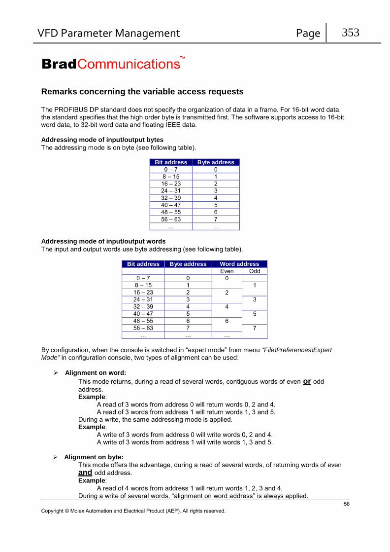
VFD Parameter Management Page 353
Remarks concerning the variable access requests
The PROFIBUS DP standard does not specify the organization of data in a frame. For 16-bit word data, the standard specifies that the high order byte is transmitted first. The software supports access to 16-bit word data, to 32-bit word data and floating IEEE data.
Addressing mode of input/output bytes
The addressing mode is on byte (see following table).
Bit address Byte address
0 – 7 0 8 – 15 1 16 – 23 2 24 – 31 3 32 – 39 4 40 – 47 5 48 – 55 6 56 – 63 7
… …
Addressing mode of input/output words
The input and output words use byte addressing (see following table).
Bit address Byte address Word address
Even Odd 0 – 7 0 0 8 – 15 1 1 16 – 23 2 2 24 – 31 3 3 32 – 39 4 4 40 – 47 5 5 48 – 55 6 6 56 – 63 7 7
… … …
By configuration, when the console is switched in “expert mode” from menu “File\Preferences\Expert Mode” in configuration console, two types of alignment can be used:
Alignment on word:
This mode returns, during a read of several words, contiguous words of even or odd
address. Example:
A read of 3 words from address 0 will return words 0, 2 and 4. A read of 3 words from address 1 will return words 1, 3 and 5.
During a write, the same addressing mode is applied. Example:
A write of 3 words from address 0 will write words 0, 2 and 4. A write of 3 words from address 1 will write words 1, 3 and 5.
Alignment on byte:
This mode offers the advantage, during a read of several words, of returning words of even
and odd address.
Example:
A read of 4 words from address 1 will return words 1, 2, 3 and 4. During a write of several words, “alignment on word address” is always applied.
58
Copyright © Molex Automation and Electrical Product (AEP). All rights reserved.

VFD Parameter Management Page 354
Addressing mode of input/output double or floating words
The input and output double or floating words use byte addressing (see following table).
Byte address Double word
address 0 0 1 1 2 2 3 3 4 4 5 5 6 6 7 7 8 8 9 9 10 10 11 11 12 12 … …
By configuration, when the console is switched in “expert mode”, three types of alignment can be used: Alignment on double word:
This mode returns, during a read of several double words, contiguous double words with address step of 4.
Example:
A read of 3 double words from address 0 will return double words 0, 4 and 8. A read of 3 double words from address 1 will return double words 1, 5 and 9. A read of 3 double words from address 2 will return double words 2, 6 and 10.
During a write of several double words, “alignment on double word address” is applied.
Alignment on word:
This mode returns, during a read of several double words, contiguous double words of even or odd address.
Example:
A read of 3 double words from address 0 will return words 0, 2 and 4. A read of 3 double words from address 1 will return words 1, 3 and 5.
During a write of several double words, “alignment on double word address” is applied.
Alignment on byte:
This mode offers the advantage, during a read of several double words, of returning double words
of even and odd address.
Example:
A read of 4 words from address 1 will return double words 1, 2, 3 and 4. During a write of several double words, “alignment on double word address” is applied.
59
Copyright © Molex Automation and Electrical Product (AEP). All rights reserved.
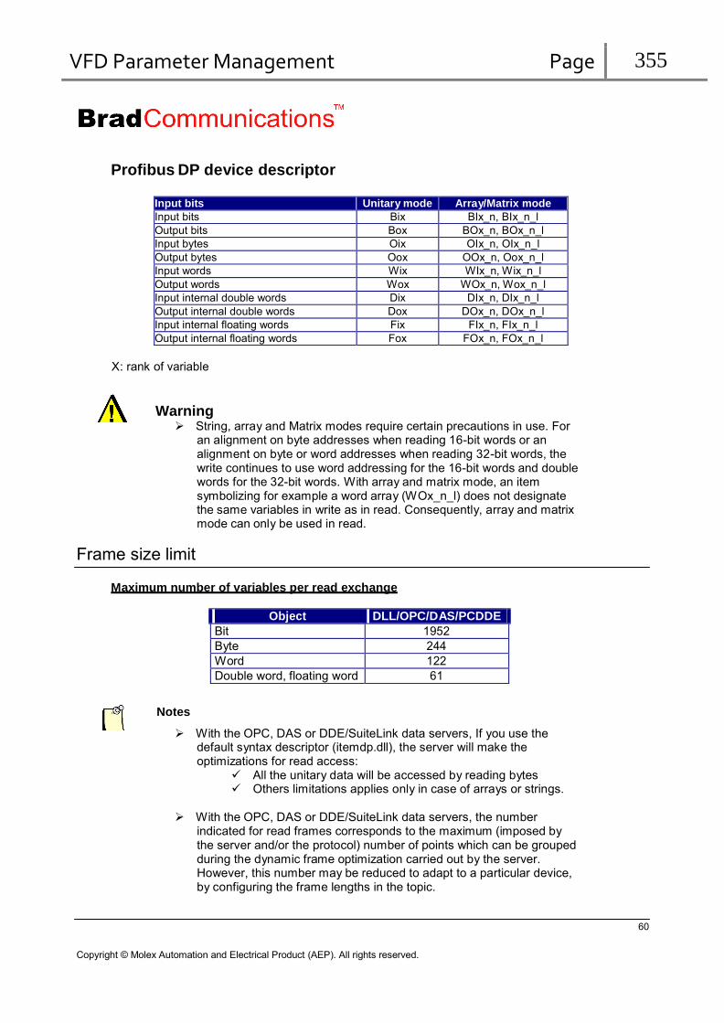
VFD Parameter Management Page 355
Profibus DP device descriptor
Input bits Unitary mode Array/Matrix mode Input bits Bix BIx_n, BIx_n_l Output bits Box BOx_n, BOx_n_l Input bytes Oix OIx_n, OIx_n_l Output bytes Oox OOx_n, Oox_n_l Input words Wix WIx_n, Wix_n_l Output words Wox WOx_n, Wox_n_l Input internal double words Dix DIx_n, DIx_n_l Output internal double words Dox DOx_n, DOx_n_l Input internal floating words Fix FIx_n, FIx_n_l Output internal floating words Fox FOx_n, FOx_n_l
X: rank of variable
Warning String, array and Matrix modes require certain precautions in use. For
an alignment on byte addresses when reading 16-bit words or an alignment on byte or word addresses when reading 32-bit words, the write continues to use word addressing for the 16-bit words and double words for the 32-bit words. With array and matrix mode, an item symbolizing for example a word array (WOx_n_l) does not designate the same variables in write as in read. Consequently, array and matrix mode can only be used in read.
Frame size limit
Maximum number of variables per read exchange
Object DLL/OPC/DAS/PCDDE Bit 1952 Byte 244 Word 122 Double word, floating word 61
Notes
With the OPC, DAS or DDE/SuiteLink data servers, If you use the default syntax descriptor (itemdp.dll), the server will make the optimizations for read access:
All the unitary data will be accessed by reading bytes Others limitations applies only in case of arrays or strings.
With the OPC, DAS or DDE/SuiteLink data servers, the number
indicated for read frames corresponds to the maximum (imposed by the server and/or the protocol) number of points which can be grouped during the dynamic frame optimization carried out by the server. However, this number may be reduced to adapt to a particular device, by configuring the frame lengths in the topic.
60
Copyright © Molex Automation and Electrical Product (AEP). All rights reserved.
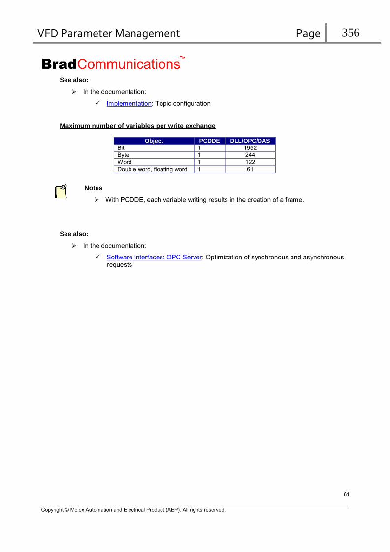
VFD Parameter Management Page 356
See also:
In the documentation:
Implementation: Topic configuration
Maximum number of variables per write exchange
Object PCDDE DLL/OPC/DAS
Bit 1 1952 Byte 1 244 Word 1 122 Double word, floating word 1 61
Notes
With PCDDE, each variable writing results in the creation of a frame.
See also:
In the documentation:
Software interfaces: OPC Server: Optimization of synchronous and asynchronous requests
61
Copyright © Molex Automation and Electrical Product (AEP). All rights reserved.

VFD Parameter Management Page 357
Access to Specific Services of Profibus DP messaging (DPV0, DPV1)
To access to Profibus DPV1 Data or specific DPV0 functionality it is necessary to use the Service interface only available as DLL command. These Service interface is not available over any of our data servers like OPC, DDE, Suite/Link, DAServer.
This Service Interface can be accessed through the DLL Function: AuWriteReadMsg.
These specific Profibus DP services can also be used from the diagnostic tool via the tabs DP-V0, DP-V1 C1 and DP-V1 C2.
62
Copyright © Molex Automation and Electrical Product (AEP). All rights reserved.

VFD Parameter Management Page 358
AuWriteReadMsg:
The “AuWriteReadMsg” function provides Profibus DP-V0 and DP-V1 services:
Get configuration from the device (Get Config).
Read input from the device (Read Input).
Read output from the device (Read_Output).
Read diagnostic function from the device (Slave Diag).
Write a command in the device (Global Control).
Configure the Profibus Address in a remote device (Set_Slave_Add)
DP-V1 Class1 Read and Write
DP-V1 Class2 Read and Write
DP-V1 Class2 Abort
This function requires the following 8 parameters: wChan: 16-bit word indicating the targeted channel. wEquip: 16-bit word indicating the number of the targeted device.
dwMsgParam: 32-bit word indicating the service.
Service Function 56 DPV0_C2_DDLM_Read_Input 57 DPV0_C2_DDLM_Read_Output 58 DPV0_C1_DDLM_Global_Control 59 DPV0_C2_DDLM_Get_Config 60 DPV0_C2_DDLM_Slave_Diag 0x10037 DPV0_C2_DDLM_Set_Slave_Add 67 DPV1_C1_MSAC1_Read 68 DPV1_C1_MSAC1_Write 69 DPV1_C2_MSAC2_Read 70 DPV1_C2_MSAC2_Write 72 DPV1_C2_MSAC2_Abort
wNbTx: Number of bytes to transmit to the lpbyBufTx buffer. lpbyBufTx: Near pointer to the transmission buffer. Up to 244 bytes of data can be placed in the
transmission message. pwNbRx: Near pointer to the number of bytes received. The return value indicates the num ber of
bytes received, if the variable indicated by pdwStatus is equal to zero. lpbyBufRx: Near pointer to the reception buffer. Up to 244 bytes of data can be received in the
buffer. pdwStatus: near pointer to an error status 32-bit wor
63
Copyright © Molex Automation and Electrical Product (AEP). All rights reserved.

VFD Parameter Management Page 359
Diagnostic request
The function “AuWriteReadMsg” can be used to read the device diagnostic.
This function requires the following 8 parameters: wChan: 16-bit word indicating the targeted channel. wEquip: 16-bit word indicating the number of the configured device. dwMsgParam: 32-bit word initialized to the value 60. wNbTx: Number of bytes to transmit to the lpbyBufTx buffer. lpbyBufTx: Near pointer to the transmission buffer. Up to 244 bytes of data can be placed in the
transmission message. pwNbRx: Near pointer to the number of bytes received. The return value indicates the number of
bytes received, if the variable indicated by pdwStatus is equal to zero. lpbyBufRx: Near pointer to the reception buffer. Up to 244 bytes of data can be received in the
buffer. pdwStatus: near pointer to an error status 32-bit word
#include "applicom.h" /* Statement File*/
void DPV0_C2_DDLM_Slave_Diag(WORD wChan)
{
DWORD dwMsgParam = 60; /* SAP for Read Slave Diagnostic */
WORD wEquip; /* device number */ WORD wNbTx = 0; /* Number of bytes to send */ BYTE byTxBuf[MAX_BUFFER_SIZE]; /* send buffer */ BYTE byRxBuf[MAX_BUFFER_SIZE]; /* receive buffer */ WORD wNbRx = sizeof(byRxBuf); /* number of bytes received */ DWORD dwStatus; /* return code */
printf("Read Slave Diagnostic\r\n");
wEquip = (WORD)PrintAndScan("Device Number :","%u"); /* Get device number */
AuWriteReadMsg (wChan, /* Channel number */
wEquip, /* number */
dwMsgParam, /* service */ wNbTx, /* Number of bytes to send */ byTxBuf, /* send buffer */ &wNbRx, /* number of bytes received */ byRxBuf, /* receive buffer */ &dwStatus ); /* return code */
if (dwStatus == 0) /* get return status */
{ /* if no error */
printf("Response Len: %u Data: %s \r\n",wNbRx,DumpData(byRxBuf,wNbRx));
}
else
{/* Error code analysis */
printf("Error : \r\n%s \r\n",GetStatusDefinition(dwStatus));
}
}
64
Copyright © Molex Automation and Electrical Product (AEP). All rights reserved.

VFD Parameter Management Page 360
Read IO configuration
The function “AuWriteReadMsg” can be used to read the device configuration string.
This function requires the following 8 parameters: wChan: 16-bit word indicating the targeted channel. wEquip: 16-bit word indicating the number of the configured device. dwMsgParam: 32-bit word initialized to the value 59. wNbTx: Number of bytes to transmit to the lpbyBufTx buffer. lpbyBufTx: Near pointer to the transmission buffer. Up to 244 bytes of data can be placed in the
transmission message. pwNbRx: Near pointer to the number of bytes received. The return value indicates the number of
bytes received, if the variable indicated by pdwStatus is equal to zero. lpbyBufRx: Near pointer to the reception buffer. Up to 244 bytes of data can be received in the
buffer. pdwStatus: near pointer to an error status 32-bit word
#include "applicom.h" /* Statement File*/
void DPV0_C2_DDLM_Get_Config(WORD wChan)
{
DWORD dwMsgParam = 59; /* SAP for Read Configuration */
WORD wEquip; /* device number */
WORD wNbTx = 0; /* Number of bytes to send */
BYTE byTxBuf[MAX_BUFFER_SIZE]; /* send buffer */
BYTE byRxBuf[MAX_BUFFER_SIZE]; /* receive buffer */
WORD wNbRx = sizeof(byRxBuf); /* number of bytes received */
DWORD dwStatus; /* return code */
printf("Read Slave Configuration\r\n");
wEquip = (WORD)PrintAndScan(" Device Number :","%u");
AuWriteReadMsg (wChan, /* Channel number
/* Get
device number */
*/
wEquip, /* number */ dwMsgParam, /* service */ wNbTx, /* Number of bytes to send */ byTxBuf, /* send buffer */ &wNbRx, /* number of bytes received */ byRxBuf, /* receive buffer */ &dwStatus ); /* return code */
if (dwStatus == 0) /* get return status */
{ /* if no error */
printf("Response Len: %u Data: %s \r\n",wNbRx,DumpData(byRxBuf,wNbRx));
}
else
{/* Error code analysis */
printf("Error : \r\n%s \r\n",GetStatusDefinition(dwStatus));
}
}
65
Copyright © Molex Automation and Electrical Product (AEP). All rights reserved.

VFD Parameter Management Page 361
Read all input data of a device
The function “AuWriteReadMsg” can be used to read all inputs data of a device.
This function requires the following 8 parameters: wChan: 16-bit word indicating the targeted channel, wEquip: 16-bit word indicating the number of the configured device. dwMsgParam: 32-bit word initialized to the value 56. wNbTx: Number of bytes to transmit to the lpbyBufTx buffer. lpbyBufTx: Near pointer to the transmission buffer. Up to 244 bytes of data can be placed in the
transmission message. pwNbRx: Near pointer to the number of bytes received. The return value indicates the number of
bytes received, if the variable indicated by pdwStatus is equal to zero. lpbyBufRx: Near pointer to the reception buffer. Up to 244 bytes of data can be received in the
buffer. pdwStatus: near pointer to status 32-bit word
#include "applicom.h" /* Statement File*/
void DPV0_C2_DDLM_Read_Input (WORD wChan)
{
DWORD dwMsgParam = 56; /* SAP for Read Input */ WORD wEquip; /* number equip */ WORD wNbTx = 0; /* Number of bytes to send */ BYTE byTxBuf[MAX_BUFFER_SIZE]; /* send buffer */ BYTE byRxBuf[MAX_BUFFER_SIZE]; /* receive buffer */ WORD wNbRx = sizeof(byRxBuf); /* number of bytes received */ DWORD dwStatus;
printf("Read Slave Input\r\n");
/* return code */
wEquip = (WORD)PrintAndScan(" Device Number :","%u"); /* Get device number */
AuWriteReadMsg (wChan, /* Channel number */
wEquip, /* number */
dwMsgParam, /* service */ wNbTx, /* Number of bytes to send */ byTxBuf, /* send buffer */ &wNbRx, /* number of bytes received */ byRxBuf, /* receive buffer */ &dwStatus ); /* return code */
if (dwStatus == 0) /* get return status */
{ /* if no error */
printf("Response Len: %u Data: %s \r\n",wNbRx,DumpData(byRxBuf,wNbRx));
}
else
{/* Error code analysis */
printf("Error : \r\n%s \r\n",GetStatusDefinition(dwStatus));
}
}
66
Copyright © Molex Automation and Electrical Product (AEP). All rights reserved.

VFD Parameter Management Page 362
Read all output data of a device
The function “AuWriteReadMsg” can be used to read all outputs of a device.
This function requires the following 8 parameters: wChan: 16-bit word indicating the targeted channel. wEquip: 16-bit word indicating the number of the configured device. dwMsgParam: 32-bit word initialized to the value 57. wNbTx: Number of bytes to transmit to the lpbyBufTx buffer. lpbyBufTx: Near pointer to the transmission buffer. Up to 244 bytes of data can be placed in the
transmission message. pwNbRx: Near pointer to the number of bytes received. The return value indicates the number of
bytes received, if the variable indicated by pdwStatus is equal to zero. lpbyBufRx: Near pointer to the reception buffer. Up to 244 bytes of data can be received in the
buffer. pdwStatus: near pointer to an error status 32-bit word
#include "applicom.h" /* Statement File*/
void DPV0_C2_DDLM_Read_Output(WORD wChan)
{
DWORD dwMsgParam = 57; /* SAP for Read Output */ WORD wEquip; /* number Equip */ WORD wNbTx = 0; /* Number of bytes to send */ BYTE byTxBuf[MAX_BUFFER_SIZE]; /* send buffer */ BYTE byRxBuf[MAX_BUFFER_SIZE]; /* receive buffer */ WORD wNbRx = sizeof(byRxBuf); /* number of bytes received */ DWORD dwStatus;
printf("Read Slave Output\r\n");
/* return code */
wEquip = (WORD)PrintAndScan(" Device Number :","%u"); /* Get device number */
AuWriteReadMsg (wChan, /* Channel number */
wEquip, /* number */
dwMsgParam, /* service */ wNbTx, /* Number of bytes to send */ byTxBuf, /* send buffer */ &wNbRx, /* number of bytes received */ byRxBuf, /* receive buffer */ &dwStatus ); /* return code */
if (dwStatus == 0) /* get return status */
{ /* if no error */
printf("Response Len: %u Data: %s \r\n",wNbRx,DumpData(byRxBuf,wNbRx));
}
else
{/* Error code analysis */
printf("Error : \r\n%s \r\n",GetStatusDefinition(dwStatus));
}
}
67
Copyright © Molex Automation and Electrical Product (AEP). All rights reserved.
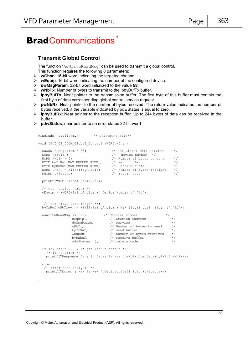
VFD Parameter Management Page 363
Transmit Global Control
The function “AuWriteReadMsg” can be used to transmit a global control.
This function requires the following 8 parameters: wChan: 16-bit word indicating the targeted channel. wEquip: 16-bit word indicating the number of the configured device. dwMsgParam: 32-bit word initialized to the value 58. wNbTx: Number of bytes to transmit to the lpbyBufTx buffer. lpbyBufTx: Near pointer to the transmission buffer. The first byte of this buffer must contain the
first byte of data corresponding global control service request. pwNbRx: Near pointer to the number of bytes received. The return value indicates the number of
bytes received, if the variable indicated by pdwStatus is equal to zero. lpbyBufRx: Near pointer to the reception buffer. Up to 244 bytes of data can be received in the
buffer. pdwStatus: near pointer to an error status 32-bit word
#include "applicom.h" /* Statement File*/
void DPV0_C1_DDLM_Global_Control (WORD wChan)
{
DWORD dwMsgParam = 58; /* Set Global ctrl service */
WORD wEquip ; /* device number */ WORD wNbTx = 0; /* Number of bytes to send */ BYTE byTxBuf[MAX_BUFFER_SIZE]; /* send buffer */ BYTE byRxBuf[MAX_BUFFER_SIZE]; /* receive buffer */ WORD wNbRx = sizeof(byRxBuf); /* number of bytes received */ DWORD dwStatus;
printf("Set Global Ctrl\r\n");
/* return code */
/* Get device number */
wEquip = (WORD)PrintAndScan(" Device Number :","%u");
/* Get slave data length */;
byTxBuf[wNbTx++] = (BYTE)PrintAndScan("New Global ctrl value :","%u");
AuWriteReadMsg (wChan, /* Channel number */
wEquip , /* Station address */
dwMsgParam, /* service */
wNbTx, /* Number of bytes to send */
byTxBuf, /* send buffer */
&wNbRx, /* number of bytes received */
byRxBuf, /* receive buffer */
&dwStatus ); /* return code */
if (dwStatus == 0) /* get return status */
{ /* if no error */
printf("Response Len: %u Data: %s \r\n",wNbRx,DumpData(byRxBuf,wNbRx));
}
else
{/* Error code analysis */
printf("Error : \r\n%s \r\n",GetStatusDefinition(dwStatus));
}
}
68
Copyright © Molex Automation and Electrical Product (AEP). All rights reserved.
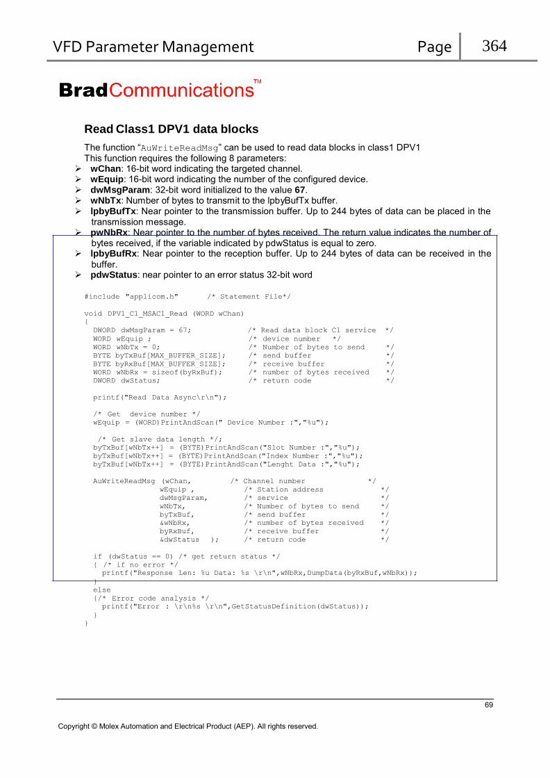
VFD Parameter Management Page 364
Read Class1 DPV1 data blocks
The function “AuWriteReadMsg” can be used to read data blocks in class1 DPV1 This function requires the following 8 parameters:
wChan: 16-bit word indicating the targeted channel. wEquip: 16-bit word indicating the number of the configured device. dwMsgParam: 32-bit word initialized to the value 67. wNbTx: Number of bytes to transmit to the lpbyBufTx buffer. lpbyBufTx: Near pointer to the transmission buffer. Up to 244 bytes of data can be placed in the
transmission message. pwNbRx: Near pointer to the number of bytes received. The return value indicates the number of
bytes received, if the variable indicated by pdwStatus is equal to zero. lpbyBufRx: Near pointer to the reception buffer. Up to 244 bytes of data can be received in the
buffer. pdwStatus: near pointer to an error status 32-bit word
#include "applicom.h" /* Statement File*/
void DPV1_C1_MSAC1_Read (WORD wChan)
{
DWORD dwMsgParam = 67; /* Read data block C1 service */
WORD wEquip ; /* device number */ WORD wNbTx = 0; /* Number of bytes to send */ BYTE byTxBuf[MAX_BUFFER_SIZE]; /* send buffer */ BYTE byRxBuf[MAX_BUFFER_SIZE]; /* receive buffer */ WORD wNbRx = sizeof(byRxBuf); /* number of bytes received */ DWORD dwStatus;
printf("Read Data Async\r\n");
/* return code */
/* Get device number */
wEquip = (WORD)PrintAndScan(" Device Number :","%u");
/* Get slave data length */;
byTxBuf[wNbTx++] = (BYTE)PrintAndScan("Slot Number :","%u");
byTxBuf[wNbTx++] = (BYTE)PrintAndScan("Index Number :","%u");
byTxBuf[wNbTx++] = (BYTE)PrintAndScan("Lenght Data :","%u");
AuWriteReadMsg (wChan, /* Channel number */
wEquip , /* Station address */
dwMsgParam, /* service */
wNbTx, /* Number of bytes to send */
byTxBuf, /* send buffer */
&wNbRx, /* number of bytes received */
byRxBuf, /* receive buffer */
&dwStatus ); /* return code */
if (dwStatus == 0) /* get return status */
{ /* if no error */
printf("Response Len: %u Data: %s \r\n",wNbRx,DumpData(byRxBuf,wNbRx));
}
else
{/* Error code analysis */
printf("Error : \r\n%s \r\n",GetStatusDefinition(dwStatus));
}
}
69
Copyright © Molex Automation and Electrical Product (AEP). All rights reserved.

VFD Parameter Management Page 365
Write Class1 DPV1 data blocks The function “AuWriteReadMsg” can be used to write data blocks in class1 DPV1 This function requires the following 8 parameters:
wChan: 16-bit word indicating the targeted channel. wEquip: 16-bit word indicating the number of the configured device. dwMsgParam: 32-bit word initialized to the value 68. wNbTx: Number of bytes to transmit to the lpbyBufTx buffer. lpbyBufTx: Near pointer to the transmission buffer. Up to 244 bytes of data can be placed in the
transmission message. pwNbRx: Near pointer to the number of bytes received. The return value indicates the number of
bytes received, if the variable indicated by pdwStatus is equal to zero. lpbyBufRx: Near pointer to the reception buffer. Up to 244 bytes of data can be received in the
buffer. pdwStatus: near pointer to an error status 32-bit word
#include "applicom.h" /* Statement File*/
void DPV1_C1_MSAC1_Write (WORD wChan)
{
DWORD dwMsgParam = 68; /* Write data block C1 service */
WORD wEquip ; /* device number */ WORD wNbTx = 0; /* Number of bytes to send */ BYTE byTxBuf[MAX_BUFFER_SIZE]; /* send buffer */ BYTE byRxBuf[MAX_BUFFER_SIZE]; /* receive buffer */ WORD wNbRx = sizeof(byRxBuf); /* number of bytes received */ DWORD dwStatus; /* return code */ WORD wLen;
printf("Write Data Async\r\n");
/* Get device number */
wEquip = (WORD)PrintAndScan(" Device Number :","%u");
/* Get slave data length */;
byTxBuf[wNbTx++] = (BYTE)PrintAndScan("Slot Number :","%u");
byTxBuf[wNbTx++] = (BYTE)PrintAndScan("Index Number :","%u");
wLen = byTxBuf[wNbTx++] = (BYTE)PrintAndScan("Lenght Data :","%u");
if (wLen)
{
if ( (wLen <= (244 -3)) )
{ /* Get slave data */;
GetData(&byTxBuf[wNbTx],wLen);
wNbTx += wLen;
}
else
{ /* length error */
printf("Error : \r\n%s \r\n",GetStatusDefinition(21));
return;
}
}
AuWriteReadMsg (wChan, /* Channel number */
wEquip , /* Station address */
dwMsgParam, /* service */
wNbTx, /* Number of bytes to send */
byTxBuf, /* send buffer */
&wNbRx, /* number of bytes received */
byRxBuf, /* receive buffer */
&dwStatus ); /* return code */
if (dwStatus == 0) /* get return status */
{ /* if no error */
printf("Response Len: %u Data: %s \r\n",wNbRx,DumpData(byRxBuf,wNbRx));
}
else
{/* Error code analysis */
printf("Error : \r\n%s \r\n",GetStatusDefinition(dwStatus));
}
}
70

VFD Parameter Management Page 366
Read Class2 DPV1 data blocks
The function “AuWriteReadMsg” can be used to read data blocks in class2 DPV1 This function requires the following 8 parameters: The initiate frame is sending automatically. This frame can be configured by the console of configuration.
wChan: 16-bit word indicating the targeted channel. wEquip: 16-bit word indicating the number of the configured device. dwMsgParam: 32-bit word initialized to the value 69. wNbTx: Number of bytes to transmit to the lpbyBufTx buffer. lpbyBufTx: Near pointer to the transmission buffer. Up to 244 bytes of data can be placed in the
transmission message. pwNbRx: Near pointer to the number of bytes received. The return value indicates the number of
bytes received, if the variable indicated by pdwStatus is equal to zero. lpbyBufRx: Near pointer to the reception buffer. Up to 244 bytes of data can be received in the
buffer. pdwStatus: near pointer to an error status 32-bit word
#include "applicom.h" /* Statement File*/
void DPV1_C2_MSAC2_Read (WORD wChan)
{
DWORD dwMsgParam = 69; /* Read data bloc C2 service */
WORD wEquip ; /* device number */ WORD wNbTx = 0; /* Number of bytes to send */ BYTE byTxBuf[MAX_BUFFER_SIZE]; /* send buffer */ BYTE byRxBuf[MAX_BUFFER_SIZE]; /* receive buffer */ WORD wNbRx = sizeof(byRxBuf); /* number of bytes received */ DWORD dwStatus;
printf("Read Data Async\r\n");
/* return code */
/* Get device number */
wEquip = (WORD)PrintAndScan(" Device Number :","%u");
/* Get slave data length */;
byTxBuf[wNbTx++] = (BYTE)PrintAndScan("Slot Number :","%u");
byTxBuf[wNbTx++] = (BYTE)PrintAndScan("Index Number :","%u");
byTxBuf[wNbTx++] = (BYTE)PrintAndScan("Lenght Data :","%u");
AuWriteReadMsg (wChan, /* Channel number */
wEquip , /* Station address */
dwMsgParam, /* service */
wNbTx, /* Number of bytes to send */
byTxBuf, /* send buffer */
&wNbRx, /* number of bytes received */
byRxBuf, /* receive buffer */
&dwStatus ); /* return code */
if (dwStatus == 0) /* get return status */
{ /* if no error */
printf("Response Len: %u Data: %s \r\n",wNbRx,DumpData(byRxBuf,wNbRx));
}
else
{/* Error code analysis */
printf("Error : \r\n%s \r\n",GetStatusDefinition(dwStatus));
}
}
71
Copyright © Molex Automation and Electrical Product (AEP). All rights reserved.

VFD Parameter Management Page 367
Write Class2 DPV1 data blocks
The function “AuWriteReadMsg” can be used to write data blocks in class2 DPV1 This function requires the following 8 parameters: The initiate frame is sending automatically. This frame can be configured by the console of configuration.
wChan: 16-bit word indicating the targeted channel. wEquip: 16-bit word indicating the number of the configured device. dwMsgParam: 32-bit word initialized to the value 70. wNbTx: Number of bytes to transmit to the lpbyBufTx buffer. lpbyBufTx: Near pointer to the transmission buffer. Up to 244 bytes of data can be placed in the
transmission message. pwNbRx: Near pointer to the number of bytes received. The return value indicates the number of
bytes received, if the variable indicated by pdwStatus is equal to zero. lpbyBufRx: Near pointer to the reception buffer. Up to 244 bytes of data can be received in the
buffer. pdwStatus: near pointer to an error status 32-bit word
#include "applicom.h" /* Statement File*/
void DPV1_C2_MSAC2_Write (WORD wChan)
{
DWORD dwMsgParam = 70; /* Write data bloc C2 service */
WORD wEquip ; /* device number */ WORD wNbTx = 0; /* Number of bytes to send */ BYTE byTxBuf[MAX_BUFFER_SIZE]; /* send buffer */ BYTE byRxBuf[MAX_BUFFER_SIZE]; /* receive buffer */ WORD wNbRx = sizeof(byRxBuf); /* number of bytes received */ DWORD dwStatus; /* return code */ WORD wLen;
printf("Write Data Async\r\n");
/* Get device number */
wEquip = (WORD)PrintAndScan(" Device Number :","%u");
/* Get slave data length */;
byTxBuf[wNbTx++] = (BYTE)PrintAndScan("Slot Number :","%u");
byTxBuf[wNbTx++] = (BYTE)PrintAndScan("Index Number :","%u");
wLen = byTxBuf[wNbTx++] = (BYTE)PrintAndScan("Lenght Data :","%u");
if (wLen)
{
if ( (wLen <= (244 -3)) )
{ /* Get slave data */;
GetData(&byTxBuf[wNbTx],wLen);
wNbTx += wLen;
}
else
{ /* length error */
printf("Error : \r\n%s \r\n",GetStatusDefinition(21));
return;
}
}
AuWriteReadMsg (wChan, /* Channel number */
wEquip , /* Station address */
dwMsgParam, /* service */
wNbTx, /* Number of bytes to send */
byTxBuf, /* send buffer */
&wNbRx, /* number of bytes received */
byRxBuf, /* receive buffer */
&dwStatus ); /* return code */
if (dwStatus == 0) /* get return status */
{ /* if no error */
printf("Response Len: %u Data: %s \r\n",wNbRx,DumpData(byRxBuf,wNbRx));
}
else
{/* Error code analysis */
printf("Error : \r\n%s \r\n",GetStatusDefinition(dwStatus));
}
}
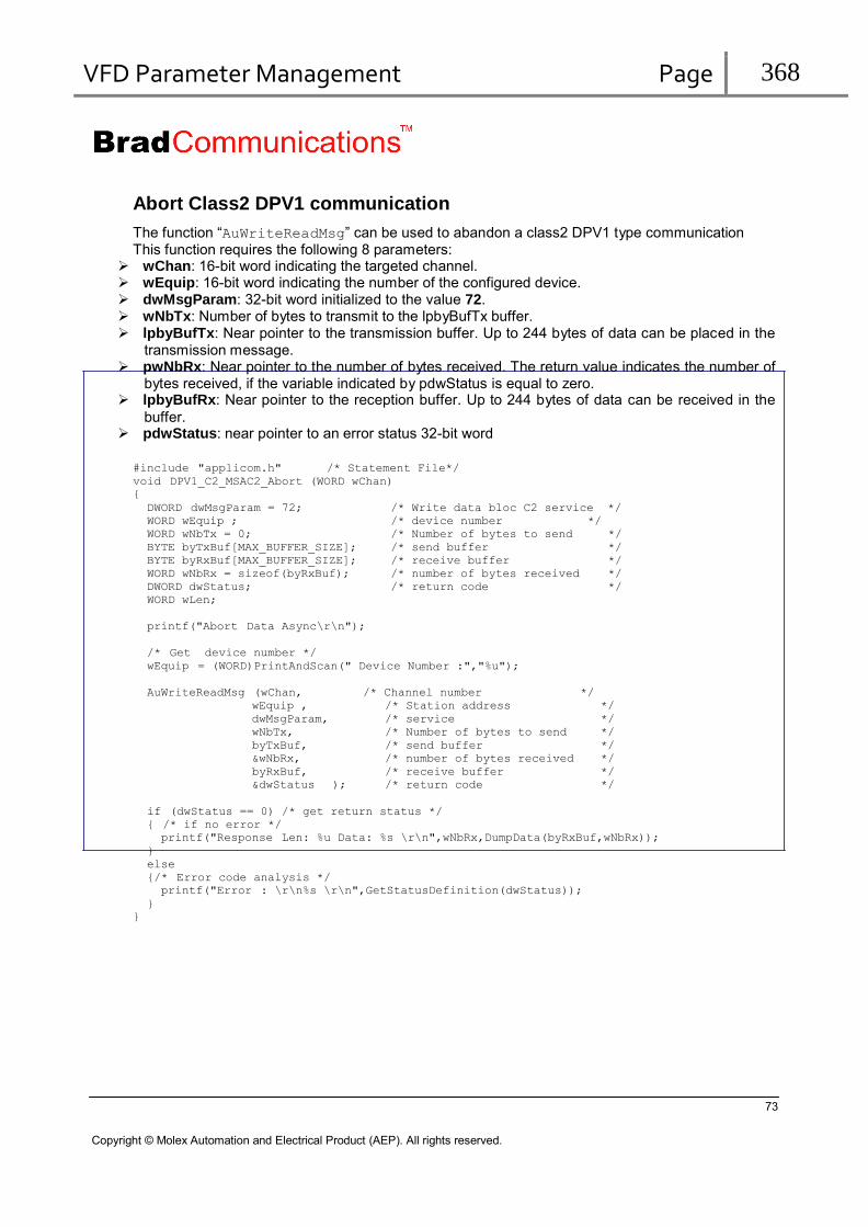
VFD Parameter Management Page 368
Abort Class2 DPV1 communication
The function “AuWriteReadMsg” can be used to abandon a class2 DPV1 type communication This function requires the following 8 parameters:
wChan: 16-bit word indicating the targeted channel. wEquip: 16-bit word indicating the number of the configured device. dwMsgParam: 32-bit word initialized to the value 72. wNbTx: Number of bytes to transmit to the lpbyBufTx buffer. lpbyBufTx: Near pointer to the transmission buffer. Up to 244 bytes of data can be placed in the
transmission message. pwNbRx: Near pointer to the number of bytes received. The return value indicates the number of
bytes received, if the variable indicated by pdwStatus is equal to zero. lpbyBufRx: Near pointer to the reception buffer. Up to 244 bytes of data can be received in the
buffer. pdwStatus: near pointer to an error status 32-bit word
#include "applicom.h" /* Statement File*/
void DPV1_C2_MSAC2_Abort (WORD wChan)
{
DWORD dwMsgParam = 72; /* Write data bloc C2 service */
WORD wEquip ; /* device number */
WORD wNbTx = 0; /* Number of bytes to send */
BYTE byTxBuf[MAX_BUFFER_SIZE]; /* send buffer */
BYTE byRxBuf[MAX_BUFFER_SIZE]; /* receive buffer */
WORD wNbRx = sizeof(byRxBuf); /* number of bytes received */
DWORD dwStatus; /* return code */
WORD wLen;
printf("Abort Data Async\r\n");
/* Get device number */
wEquip = (WORD)PrintAndScan(" Device Number :","%u");
AuWriteReadMsg (wChan, /* Channel number */
wEquip , /* Station address */
dwMsgParam, /* service */
wNbTx, /* Number of bytes to send */
byTxBuf, /* send buffer */
&wNbRx, /* number of bytes received */
byRxBuf, /* receive buffer */
&dwStatus ); /* return code */
if (dwStatus == 0) /* get return status */
{ /* if no error */
printf("Response Len: %u Data: %s \r\n",wNbRx,DumpData(byRxBuf,wNbRx));
}
else
{/* Error code analysis */
printf("Error : \r\n%s \r\n",GetStatusDefinition(dwStatus));
}
}
73
Copyright © Molex Automation and Electrical Product (AEP). All rights reserved.
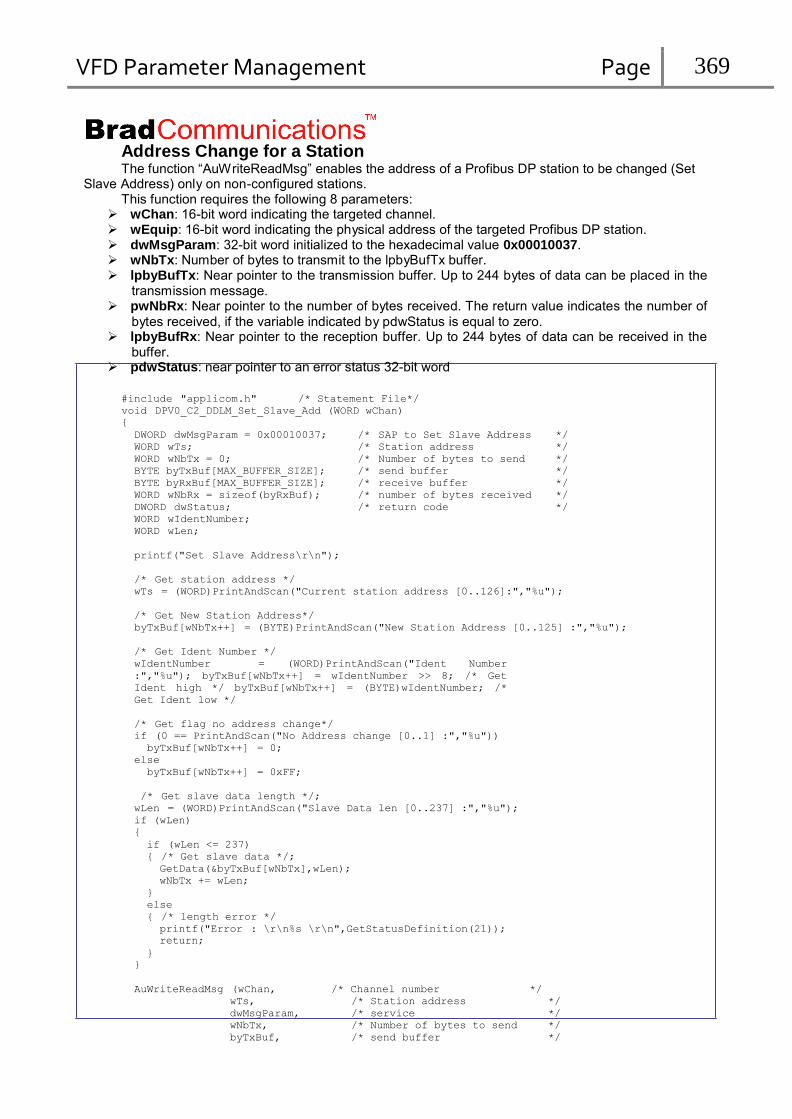
VFD Parameter Management Page 369
Address Change for a Station The function “AuWriteReadMsg” enables the address of a Profibus DP station to be changed (Set
Slave Address) only on non-configured stations. This function requires the following 8 parameters:
wChan: 16-bit word indicating the targeted channel. wEquip: 16-bit word indicating the physical address of the targeted Profibus DP station. dwMsgParam: 32-bit word initialized to the hexadecimal value 0x00010037. wNbTx: Number of bytes to transmit to the lpbyBufTx buffer. lpbyBufTx: Near pointer to the transmission buffer. Up to 244 bytes of data can be placed in the
transmission message. pwNbRx: Near pointer to the number of bytes received. The return value indicates the number of
bytes received, if the variable indicated by pdwStatus is equal to zero. lpbyBufRx: Near pointer to the reception buffer. Up to 244 bytes of data can be received in the
buffer. pdwStatus: near pointer to an error status 32-bit word
#include "applicom.h" /* Statement File*/
void DPV0_C2_DDLM_Set_Slave_Add (WORD wChan)
{
DWORD dwMsgParam = 0x00010037; /* SAP to Set Slave Address */ WORD wTs; /* Station address */ WORD wNbTx = 0; /* Number of bytes to send */ BYTE byTxBuf[MAX_BUFFER_SIZE]; /* send buffer */ BYTE byRxBuf[MAX_BUFFER_SIZE]; /* receive buffer */ WORD wNbRx = sizeof(byRxBuf); /* number of bytes received */ DWORD dwStatus; /* return code */ WORD wIdentNumber; WORD wLen;
printf("Set Slave Address\r\n");
/* Get station address */
wTs = (WORD)PrintAndScan("Current station address [0..126]:","%u");
/* Get New Station Address*/
byTxBuf[wNbTx++] = (BYTE)PrintAndScan("New Station Address [0..125] :","%u");
/* Get Ident Number */
wIdentNumber = (WORD)PrintAndScan("Ident Number
:","%u"); byTxBuf[wNbTx++] = wIdentNumber >> 8; /* Get
Ident high */ byTxBuf[wNbTx++] = (BYTE)wIdentNumber; /*
Get Ident low */
/* Get flag no address change*/
if (0 == PrintAndScan("No Address change [0..1] :","%u"))
byTxBuf[wNbTx++] = 0;
else
byTxBuf[wNbTx++] = 0xFF;
/* Get slave data length */;
wLen = (WORD)PrintAndScan("Slave Data len [0..237] :","%u");
if (wLen)
{
if (wLen <= 237)
{ /* Get slave data */;
GetData(&byTxBuf[wNbTx],wLen);
wNbTx += wLen;
}
else
{ /* length error */
printf("Error : \r\n%s \r\n",GetStatusDefinition(21));
return;
}
}
AuWriteReadMsg (wChan, /* Channel number */
wTs, /* Station address */
dwMsgParam, /* service */
wNbTx, /* Number of bytes to send */
byTxBuf, /* send buffer */

VFD Parameter Management Page 370
byRxBuf, /* receive buffer */ &dwStatus ); /* return code */
if (dwStatus == 0) /* get return status */
{ /* if no error */
printf("Response Len: %u Data: %s \r\n",wNbRx,DumpData(byRxBuf,wNbRx));
}
else
{/* Error code analysis */
printf("Error : \r\n%s \r\n",GetStatusDefinition(dwStatus));
}
}
AuWriteReadMsg sample
A Sample is available in the Product installation directory under the following sub-directory:
“Development\Visual Studio\C\Example\Profibus\ProfibusDpAuWriteReadMsg”
It contains a source file in ANSI C: ProfibusDPAuWriteReadMsg.c, and an executable file: ProfibusDpAuWriteReadMsg.exe.
To be integrated into a project or to be compiled, this file requires access to the following files: applicom.h and applicom.lib
75
Copyright © Molex Automation and Electrical Product (AEP). All rights reserved.

VFD Parameter Management Page 371
9. In case of problems
Problems resolution
Problem Suggestions
The BradCommunications
USB100PFB is connected to the machine but the LED near the USB connector remains off
Verify that the USB cable is correctly inserted on the both sides
Bad USB cable. Test with the supplied cable if another one is used
The BradCommunications
USB100PFB is connected to the machine but the LED near the USB connector remains red
The computer doesn’t recognize the device.
The driver has not been installed. Run the installation program in “modify mode” and select the S7, MPI on USB protocol
Verify in the Windows Device Manager that the USB DC100 Fieldbus adapter is present without error. If there is an error, disconnect and reconnect the BradCommunications USB100PFB on the computer, then “Scan for hardware change” in the Device Manager. If the error persists, uninstall and reinstall the software
No device present after network detection.
or
Network detection indicates a network problem.
Check your Profibus configuration on devices (address, speed)
Check the Profibus cable.
Check the master settings in the configuration console.
See also:
In this manual:
Checking stations on the Profibus network
Checking the Profibus wiring
At least, one of the two leds near the Profibus connector is not green
Check your Profibus configuration on devices (address, speed)
Check the Profibus cable.
Check the master and devices configuration in the console.
Also, check that the BradCommunications USB100PFB module is usable with usb solution.
See also:
In this manual:
Checking stations on the Profibus network
Checking the Profibus wiring
A status 55 is returned to your application
if your transmission speed is lower than 187,5 Kbds, increase the “Request Time-out” parameter in the Master parameters \Advanced Configuration tab
See also:
In this manual:
Checking stations on the Profibus network
Checking the Profibus wiring
76
Copyright © Molex Automation and Electrical Product (AEP). All rights reserved.
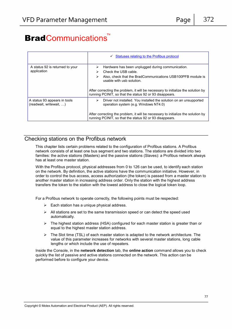
VFD Parameter Management Page 372
Statuses relating to the Profibus protocol
A status 92 is returned to your application
Hardware has been unplugged during communication.
Check the USB cable.
Also, check that the BradCommunications USB100PFB module is usable with usb solution.
After correcting the problem, it will be necessary to initialize the solution by running PCINIT, so that the status 92 or 93 disappears.
A status 93 appears in tools (readwait, writewait, …)
Driver not installed. You installed the solution on an unsupported operation system (e.g. Windows NT4.0)
After correcting the problem, it will be necessary to initialize the solution by running PCINIT, so that the status 92 or 93 disappears.
Checking stations on the Profibus network
This chapter lists certain problems related to the configuration of Profibus stations. A Profibus network consists of at least one bus segment and two stations. The stations are divided into two families: the active stations (Masters) and the passive stations (Slaves): a Profibus network always has at least one master station.
With the Profibus protocol, physical addresses from 0 to 126 can be used, to identify each station on the network. By definition, the active stations have the communication initiative. However, in order to control the bus access, access authorization (the token) is passed from a master station to another master station in increasing address order. Only the station with the highest address transfers the token to the station with the lowest address to close the logical token loop.
For a Profibus network to operate correctly, the following points must be respected:
Each station has a unique physical address.
All stations are set to the same transmission speed or can detect the speed used automatically.
The highest station address (HSA) configured for each master station is greater than or equal to the highest master station address.
The Slot time (TSL) of each master station is adapted to the network architecture. The value of this parameter increases for networks with several master stations, long cable lengths or which include the use of repeaters.
Inside the Console, in the network detection tab, the online action command allows you to check quickly the list of passive and active stations connected on the network. This action can be performed before to configure your device.
77
Copyright © Molex Automation and Electrical Product (AEP). All rights reserved.

VFD Parameter Management Page 373
Checking the Profibus wiring
This chapter lists certain problems related to the use of a Profibus cable with copper conductors assuming that the rules and directives contained in the standards concerned (standard EN50170, EMC rules, etc.) are observed. Use of connectors dedicated to Profibus is essential (SUB D 9-pin male connectors).
The integration of bus terminations on the connection device often leads to difficulties when starting the network:
Either because of incorrect configuration of the terminations.
Or due to inversion of the cable in the connector.
A Profibus cable with copper conductors must have two bus terminations at the ends of each network segment, as shown on the following figure:
R E C E IV E R
A C T IV E T E R M IN A T IO N
Activation of a termination is accessible on each connector. A Profibus connector generally has a switch, either directly visible, or connected to a tab as shown on the figure below:
A C T IV E T E R M IN A T IO N
78
Copyright © Molex Automation and Electrical Product (AEP). All rights reserved.

VFD Parameter Management Page 374
The station which has a termination activated must always be powered up.
A network operating correctly at 9.6 kbit without termination may have serious malfunctions at 1.5 Mbit since the risks of disturbance are greater at high speed.
The Profibus connectors are equipped with terminals to fit two cables. The position of the cable in the connector is important. If the cable is not connected to the correct terminal, the PROFIBUS network link will be considered as interrupted.
Token management using the Profibus protocol
There are 2 types of stations with different access rights
The active stations: They initiate exchanges.
The passive stations: They can only exchange data after having been invited by an active station.
Whether a station is active or passive depends on the device considered. Generally, simple field devices such as motor controls are passive, whereas “intelligent” devices such as PLCs are active. Many devices can be configured as either passive or active.
The DRL-MPI-USB and DRL-PFB-USB are active stations.
To prevent all the active stations accessing the bus at the same time, a station which wants to transmit must wait until it has received authorization to access the bus. It receives this authorization in the form of a special telegram, the “token”.
The token moves automatically from one active station to the next active station (in increasing
order of station address).
The token is transmitted around a logical ring, i.e. the station with the highest address sends the token to the station with the lowest address. Rule valid for each station: between transmission of the token and reception of the token there is a token rotation cycle.
Each active station “knows” the addresses of the other active stations. An active station checks
cyclically the range of addresses between it and the next active station. This range of addresses is called the “GAP”. During this check it detects the possible:
Addition of an active or passive station. Deletion of a passive station.
The GAP is an update factor, it indicates the frequency where a new cycle of Fdl_status is sent. This service builds a list of the active stations on network (LAS: list active stations). If the check shows that a new active station has been added, the new station receives the token immediately.
Two special cases result from this type of operation:
If there is only one active station and all the other stations are passive, the network operates
on the master-slave principle.
If all the stations are active, it is a purely token passage type network.
79
Copyright © Molex Automation and Electrical Product (AEP). All rights reserved.
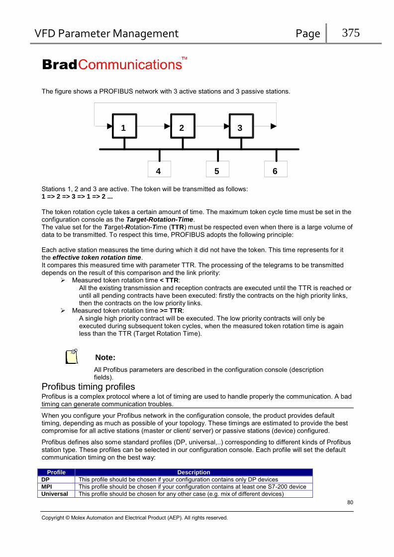
VFD Parameter Management Page 375
The figure shows a PROFIBUS network with 3 active stations and 3 passive stations.
1 2 3
4 5 6
Stations 1, 2 and 3 are active. The token will be transmitted as follows: 1 => 2 => 3 => 1 => 2 ...
The token rotation cycle takes a certain amount of time. The maximum token cycle time must be set in the configuration console as the Target-Rotation-Time. The value set for the Target-Rotation-Time (TTR) must be respected even when there is a large volume of data to be transmitted. To respect this time, PROFIBUS adopts the following principle:
Each active station measures the time during which it did not have the token. This time represents for it the effective token rotation time. It compares this measured time with parameter TTR. The processing of the telegrams to be transmitted depends on the result of this comparison and the link priority:
Measured token rotation time < TTR: All the existing transmission and reception contracts are executed until the TTR is reached or until all pending contracts have been executed: firstly the contracts on the high priority links, then the contracts on the low priority links.
Measured token rotation time >= TTR:
A single high priority contract will be executed. The low priority contracts will only be executed during subsequent token cycles, when the measured token rotation time is again less than the TTR (Target Rotation Time).
Note:
All Profibus parameters are described in the configuration console (description fields).
Profibus timing profiles Profibus is a complex protocol where a lot of timing are used to handle properly the communication. A bad timing can generate communication troubles.
When you configure your Profibus network in the configuration console, the product provides default timing, depending as much as possible of your topology. These timings are estimated to provide the best compromise for all active stations (master or client/ server) or passive stations (device) configured.
Profibus defines also some standard profiles (DP, universal,..) corresponding to different kinds of Profibus station type. These profiles can be selected in our configuration console. Each profile will set the default communication timing on the best way:
Profile Description
DP This profile should be chosen if your configuration contains only DP devices MPI This profile should be chosen if your configuration contains at least one S7-200 device Universal This profile should be chosen for any other case (e.g. mix of different devices)
80
Copyright © Molex Automation and Electrical Product (AEP). All rights reserved.

VFD Parameter Management Page 376
However, even if the profile will set the more appropriated parameters by default, some communication troubles can still happen. Indeed,
some particular devices can have specific behavior on the network (e.g S5 devices, VIPA devices for S7,…)
The network can sometimes contains other Profibus devices not included in the configuration
etc…
It can then normal to detect some communication problem after having configured your network and initialized the solution.
Min slave interval
This parameter is used for Profibus DP. This time represents the minimum interval between two data-exchanges on the same station. This is the time cycle. This time is a minimum and is not guaranteed. If, there is too many stations included in the cycle, this time couldn’t be respected. Smaller is this time, more the slave is solicited (quick data-exchanges).
In the case where only other messaging modes (S7, S5…) are used, this parameter is not used in the
same way, This time will then be used by our product to regulate the FDL_status sends. It should be then
set to largest time (set to 20, 2ms) because this service can to perturb some other stations as Simatic S5.
Using MPI Socket.
If you use a MPI socket to communicate with a S7 PLC, even if the MPI profile has been selected both in the PLC and in our configuration console, some communication troubles can appear.
Indeed, this profile can vary dramatically depending on the device.
So, if you encounter any communication problem, please refer to the technical note “Technote_Troubleshooting - MPI messaging.pdf” available from the main installation directory.
81
Copyright © Molex Automation and Electrical Product (AEP). All rights reserved.
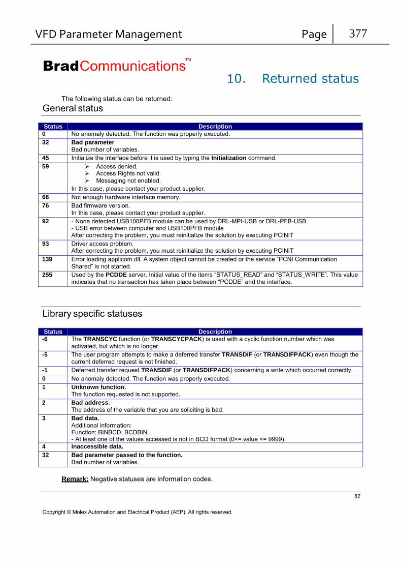
VFD Parameter Management Page 377
10. Returned status
The following status can be returned:
General status
Status Description 0 No anomaly detected. The function was properly executed. 32 Bad parameter
Bad number of variables. 45 Initialize the interface before it is used by typing the Initialization command. 59 Access denied.
Access Rights not valid.
Messaging not enabled.
In this case, please contact your product supplier. 66 Not enough hardware interface memory. 76 Bad firmware version.
In this case, please contact your product supplier. 92 - None detected USB100PFB module can be used by DRL-MPI-USB or DRL-PFB-USB.
- USB error between computer and USB100PFB module After correcting the problem, you must reinitialize the solution by executing PCINIT
93 Driver access problem. After correcting the problem, you must reinitialize the solution by executing PCINIT
139 Error loading applicom.dll. A system object cannot be created or the service “PCNI Communication
Shared” is not started. 255 Used by the PCDDE server. Initial value of the items “STATUS_READ” and “STATUS_WRITE”. This value
indicates that no transaction has taken place between “PCDDE” and the interface.
Library specific statuses
Status Description -6 The TRANSCYC function (or TRANSCYCPACK) is used with a cyclic function number which was
activated, but which is no longer. -5 The user program attempts to make a deferred transfer TRANSDIF (or TRANSDIFPACK) even though the
current deferred request is not finished. -1 Deferred transfer request TRANSDIF (or TRANSDIFPACK) concerning a write which occurred correctly. 0 No anomaly detected. The function was properly executed. 1 Unknown function.
The function requested is not supported. 2 Bad address.
The address of the variable that you are soliciting is bad. 3 Bad data.
Additional information: Function: BINBCD, BCDBIN. - At least one of the values accessed is not in BCD format (0<= value <= 9999).
4 Inaccessible data. 32 Bad parameter passed to the function.
Bad number of variables.
Remark: Negative statuses are information codes.
82
Copyright © Molex Automation and Electrical Product (AEP). All rights reserved.

VFD Parameter Management Page 378
Statuses relating to the Profibus protocol
Status Description 0 No anomaly detected. The function was executed correctly. 1 Unknown function.
The function requested is not supported. 2 Bad address.
The address of the variable that you are soliciting is bad. 3 Bad data.
Additional information: Function: BINBCD, BCDBIN, READWORDBCD, WRITEWORDBCD. - At least one of the values accessed is not in BCD format (0<= value <= 9999).
4 Inaccessible data. 6 Layer 2 negative acknowledgement by the device (NACK). 10 Layer 2 negative acknowledgement by the device (NACK).
Additional information: PROFIBUS protocol: - UE (User Error), Error in the remote device.
11 Layer 2 negative acknowledgement by the device (NACK). PROFIBUS protocol: - RR (Remote Resource), Insufficient resource in the remote device.
Or initialization parameters invalid 12 Layer 2 negative acknowledgement by the device (NACK).
Additional information: PROFIBUS protocol: - RS (Remote Service), The layer 2 service used is not allowed on the SAP or the SAP is not activated.
13 Layer 2 negative acknowledgement by the device (NACK).
Additional information: PROFIBUS protocol: - RDL (Response FDL/FMA1/2 Data Low), The resource of the remote device is insufficient to reply in low priority.
14 Layer 2 negative acknowledgement by the device (NACK).
Additional information: PROFIBUS protocol: - RDH (Response FDL/FMA1/2 Data High), The resource of the remote device is insufficient to reply in high priority.
15 PROFIBUS protocol: - LS (Local Service), local SAP not activated.
16 PROFIBUS protocol: - NO (Not Ok), Meaning depends on the layer 2 service. One LSAP is identical to another LSAP on a different communication channel.
21 PROFIBUS protocol: - IR (Invalid parameter in Request),
Additional information: TS applicom® = device address.
TS or device address > HSA 32 Bad parameter passed to the function.
Bad number of variables. 33 Response time-out fault. 34 Parity fault in reception or check word fault (CRC16, BCC).
Check the configuration of the channel and the target device. Check the wiring (RC at end of line for the RS485).
36 Device not configured.
Define the device configuration with the console and reinitialize the product. 54 PROFIBUS protocol:
- The PROFIBUS channel address is not present in the logical ring. 55 Response time-out exceeded, message lost.
PROFIBUS protocol: - Response time-out exceeded. - if your transmission speed is lower than 187,5 Kbds, increase the “Request Time-out”
parameter in the Master parameters \Advanced Configuration tab. 65 Connection denied.

VFD Parameter Management Page 379
Additional information: Bad wiring Remote stations badly configured.
67 Additional information:
84
Copyright © Molex Automation and Electrical Product (AEP). All rights reserved.

VFD Parameter Management Page 380
11. Annex A: Detect USB capability of your PC
Notes
The following annex is extracted from a Microsoft article.
Most desktop and laptop computers sold after 2002 are USB 2.0 enabled. USB 2.0 enabled means that the computer has one or more USB-enhanced host controllers. To determine if your computer running the Windows XP or Windows Server 2003 operating system has a USB-enhanced host controller, follow these steps:
1. Start Device Manager. To do so, click Start, and then click Run. In the Open box, type
devmgmt.msc, and then click OK.
2. In the Device Manager window, expand the Universal Serial Bus controllers node. Look for a host controller with the word "Enhanced" in the title. If you find one, your system has USB 2.0 capable ports and has the necessary host controller drivers.
85
Copyright © Molex Automation and Electrical Product (AEP). All rights reserved.

VFD Parameter Management Page 381
3. If you do not find an enhanced host controller in step 2, expand the Other Devices section. Look for Universal Serial Bus (USB) Controller. If you find this item, your system has USB 2.0 capable ports, but you need to install drivers for this host controller. If you do not find this item, your system does not have any USB 2.0 ports.
Do I need to install drivers for my enhanced (USB 2.0) host controller?
- Windows 2000 Service Pack 4 (SP4) - Windows XP SP1 - Windows Server 2003
Windows 2000 and Windows XP were released before USB 2.0 hardware was available, so the
drivers were released for those operating systems in the service packs. To install drivers, follow these steps:
1. Follow the procedure described in the answer to the previous question to verify that your
computer has USB 2.0 ports that required you to install a driver for the enhanced host controller.
2. In the Device Manager window, expand the Other Devices section as explained under the
previous question, and then double-click Universal Serial Bus (USB) Controller.
86
Copyright © Molex Automation and Electrical Product (AEP). All rights reserved.

VFD Parameter Management Page 382
3. On the General tab of the Properties dialog box, click Reinstall Driver.
4. In the Add New Hardware Wizard, select Install the software automatically (Recommended), and then click Next. Continue with the wizard, accepting all default options, until you reach the last page of the wizard, and then click Finish. You may have to restart your computer to finish the installation.
Power Supply Unit

VFD Parameter Management Page 383
Power Supply Unit 1/2
Primary switched-mode, 5 A, wide input voltage range AC 85-264 V D a t a s h e e t
103 mm
4.06 in
11 AUX 10 n.c.
114 mm 3 L DC - 9
4.49 in DC - 8
DC + 7
2 N DC + 6 DC - 5 DC - 4
138 mm 1 DC + 3 5.43 in DC + 2
1
Description Item-No. Pack.-unit
pcs Front-entry wiring, output voltage indication, 787-903 1 PFC (Power Factor Correction)
Industrial 125 W power supply unit
with universal input voltage range and 88 % efficiency that can be snapped onto DIN 35 rails with built-in active Power Factor-Correction → PFC > 0.97 in accordance with DIN IEC/EN 61000-3-2, class D.
This power supply unit already meets the requirements of the standard IEC/EN 61000-3-2 thanks to its active correction. This standard specifies that as of the year 2005 (probable) all units having an input power higher than 50 W must comply with specific limit values for the input current harmonic content when they are supplied by a public electrical network.
In comparison with the passive power factor correction via a large input choke, which remains normal today, the active power factor correction reduces the rms value of the input current. Thanks to this, a 10 or 16 A unit can produce more power, which reduces the unit total cost.
For higher current, the outputs of several units with epual nominal output voltage can be connected in parallel without any precautions. For higher output voltage, the connection of several outputs in series is possible without any precautions. Exceeding however the SELV value of DC 60 V the output should be connected to ground.
Technical Data
Input: Input voltage AC 85–264 V, 47-63 Hz, DC 90-250 V Input current 1.2 A (125 V); AC 0.65 A (230 V) Peak inrush current < 5 A Input fuse 6.3 A slow Function indication LED, green Max. power consumption 160 W Output: Output voltage DC 24 V, accuracy 0...+7.5 % Output power 125 W Nominal output current 5.1 A Efficiency (AC 230 V) 88 % Power factor correction (AC 230 V) > 0.97 Deviation: static load change 350 mV dyn. load change 10 – 90% 2.6–3 V at Vin ± 10 % none Peak-to-average Ripple factor 5 % Ripple voltage 50 mVtyp acc. to IEC/EN 61204 Switching peak 20 MHz ca. 20 mV Start-up time 700 ms Output current limit 1 s ... 1.5 x IN / 1.0 ... 1.1 x IN Output hold-up time 15 ms Output protection measures Overload and short-circuit protection Dielectric strength input / output AC 3 kV Nominal operating mode 100 % continuous duty

VFD Parameter Management Page 384
2/2
Primary switched-mode, 5 A, wide input voltage range AC 85-264 V D a ta s h e e t
General data:
MTBF > 600,000 h (GB, 40 °C) Vibration resistance 5 g at 10-2000 Hz Shock resistance 50 g Bump resistance 25 g Ambient operating temperature -40 °C...+60 °C Relative air humidity 93 %, no condensation Storage temperature -40 °C...+100 °C Mounting system To be snapped onto DIN rail (EN 50022)
for vertical mounting, modular Wire connection Terminal blocks with CAGE CLAMP®
(WAGO series 236) 0.08-2.5 mm² / AWG 28-14
Stripped length 5-6 mm / 0.22 in Weight 1.4 kg / 3.08 lbs Dimensions (WxHxD) (103 x 114* x 138) mm
(4.06 x 4.49* x 5.43) in * from upper edge of DIN35 rail
Standards / prescriptions EN 60950, VDE 0805, EN 50081-1, EN 50081-2, EN 50082-2, EN 60555-2, EN 61000-3-2, EN 55011/55022, EN 61000-4-2,-3,-4,-5,-6,-11 IEC/EN 61204, EN 60068 UL 1950, UL 508 Listed
WAGO Kontakttechnik GmbH & Co. KG Postfach 2880 • D-32385 Minden Tel.: 05 71 / 8 87-0 E-Mail: [email protected]
Hansastr. 27 • D-32423 Minden Fax.: 05 71 / 8 87-169 Web: http://www.wago.com
Subject to design changes 08.06.2011 / d590300e.doc
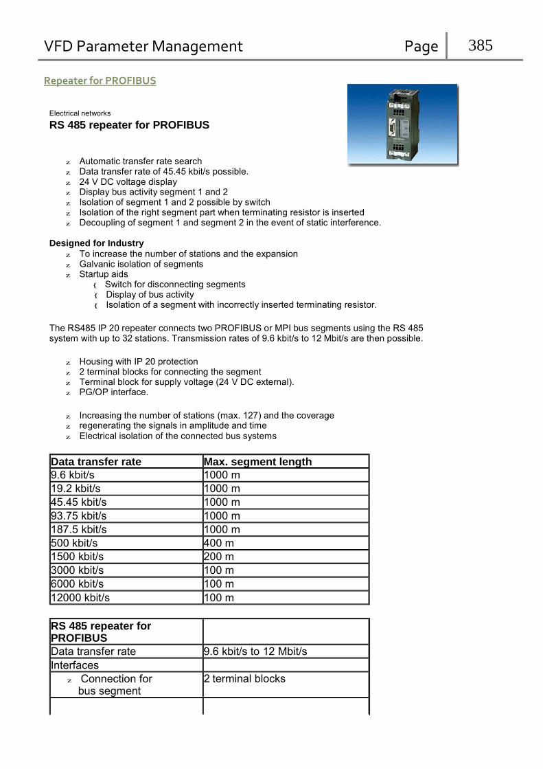
VFD Parameter Management Page 385
Repeater for PROFIBUS
Electrical networks
RS 485 repeater for PROFIBUS
z Automatic transfer rate search z Data transfer rate of 45.45 kbit/s possible. z 24 V DC voltage display z Display bus activity segment 1 and 2 z Isolation of segment 1 and 2 possible by switch z Isolation of the right segment part when terminating resistor is inserted z Decoupling of segment 1 and segment 2 in the event of static interference.
Designed for Industry z To increase the number of stations and the expansion z Galvanic isolation of segments z Startup aids
{ Switch for disconnecting segments { Display of bus activity { Isolation of a segment with incorrectly inserted terminating resistor.
The RS485 IP 20 repeater connects two PROFIBUS or MPI bus segments using the RS 485 system with up to 32 stations. Transmission rates of 9.6 kbit/s to 12 Mbit/s are then possible.
z Housing with IP 20 protection z 2 terminal blocks for connecting the segment z Terminal block for supply voltage (24 V DC external). z PG/OP interface.
z Increasing the number of stations (max. 127) and the coverage z regenerating the signals in amplitude and time z Electrical isolation of the connected bus systems
Data transfer rate Max. segment length
9.6 kbit/s 1000 m
19.2 kbit/s 1000 m
45.45 kbit/s 1000 m
93.75 kbit/s 1000 m
187.5 kbit/s 1000 m
500 kbit/s 400 m
1500 kbit/s 200 m
3000 kbit/s 100 m
6000 kbit/s 100 m
12000 kbit/s 100 m
RS 485 repeater for PROFIBUS
Data transfer rate 9.6 kbit/s to 12 Mbit/s
Interfaces
z Connection for bus segment
2 terminal blocks

VFD Parameter Management Page 386
z Connection for power terminal block
supply
Supply voltage
z Rated voltage 24 V DC (20.4 V to 28.8 V)
Current consumption at Rated voltage
z without load on PG/OP socket
z with load on PG/OP socket (5 V/90 mA)
z with load on PG/OP socket (24 V/90 mA)
Perm. environmental conditions
200 mA
230 mA
300 mA
z Operating temperature 0 °C to +60 °C
z
Transport/storage temperature
-40 °C to +70 °C
z Relative humidity max. 95% at +25 °C
Design
z Dimensions (W x H x D)
in mm
45 x 128 x 67

VFD Parameter Management Page 387
Technische Daten Spannungsversorgung
Nennspannung Welligkeit (Grenze statisch)
DC 24 V DC 20,4 V bis DC 28,8 V
Stromaufnahme bei Nennspannung max. 25 mA Potentialtrennung ja geprüft mit DC 500 V Baudrate 9,6 kBaud bis 12 MBaud Schutzart IP 20 Zulässige Umgebungstemperatur 0 C bis 60 C Lagertemperatur -- 40 C bis +70 C anschließbare Leitungen; Spannungsversorgung
flexible Leitungen -- mit Aderendhülse -- ohne Aderendhülse massive Leitungen
Schraubtechnik;
0,25 mm2 bis 1,5 mm2
0,14 mm2 bis 2,5 mm2
0,14 mm2 bis 2,5 mm2 anschließbare Leitungen; PROFIBUS Schraubtechnik; alle
SIMATIC NET PROFIBUS-Leitungen Maße B × H × T (in mm) 60 × 70 × 43 Gewicht (incl. Verpackung) ca. 95 g
Technical specifications Power supply
Rated voltage Ripple (static limit)
24 V DC 20.4 V DC to 28.8 V DC
Power input at rated voltage max 25 mA Galvanic isolation yes tested with 500 V DC Transmission rate 9.6 kbps to 12 Mbps Degree of protection IP 20 Permissible ambient temperature 0 C to 60 C Storage temperature -- 40 C to +70 C Connectable cables; power supply
Flexible cables -- With wire end ferrule -- Without wire end ferrule Solid cables
Screw type;
0.25 mm2 to 1.5 mm2
0.14 mm2 to 2.5 mm2
0.14 mm2 to 2.5 mm2 Connectable cables, PROFIBUS Screw type;
All SIMATIC NET PROFIBUS cables Dimensions W × H × D (in mm) 60 × 70 × 43 Weight (including packaging) Approx. 95 g
PROFIBUS Terminator
Deutsch
English
PROFIBUS Terminator 6ES7 972-0DA00-0AA0 PROFIBUS terminator Terminaison PROFIBUS
Bild I: Der PROFIBUS Terminator bildet einen aktiven Busabschluß. Der wesentliche Vorteil liegt darin, daß Busteilnehmer abgeschaltet, entfernt oder ausgetauscht werden können, ohne das der Da-
tentransfer beeinträchtigt wird. Dies gilt besonders für die Busteilnehmer an beiden Enden der Busleitung an denen bisher die Abschlußwiderstände zugeschaltet und versorgt sein mußten. Der
PROFIBUS Terminator läßt sich auf Normprofilschiene montieren.
Fig. I: The PROFIBUS terminator is an active bus terminator. The advantage of it is essentially that bus nodes can be switched off, removed or replaced without impairing data transfer. This applies
particularly to the bus nodes at both ends of the bus cable at which the terminating resistors previously had to be connected and supplied. The PROFIBUS terminator can be mounted on a
DIN rail.
Terminador de PROFIBUS Terminatore PROFIBUS
Product Information/Produktinformation
I
EWA 3NEB 812 6727-10a
1 LED 24 V-Spannungsversorgung 2 Anschluß für Spannungsversorgung DC 24 V 3 PROFIBUS-Anschluß 4 Schirmschelle für Erdung des Schirmgeflechts und für die Zugentlastung des Buskabels 5 Erdungsschraube 6 Schirmschelle für Zugentlastung des Kabels für Spannungsversorgung
1 24 V power supply LED 2 Connection for 24 V DC power supply 3 PROFIBUS connection 4 Shield clip for grounding the braided screen and for strain relief on the bus cable 5 Grounding screw 6 Shield clip for strain relief on the power supply cable
SIEMENS
PROFIBUS
TERMINATOR
1 DC 24 V
Bild II: Kabel abisolieren und Schirmgeflecht umstülpen bei Verwendung von:
D SIMATIC NET PROFIBUS-Leitung mit Best.-Nr.: 6XV1 830-0AH10, 6XV1 830-3BH10 nach Bild IIa.
D SIMATIC NET PROFIBUS-Leitung mit Best.-Nr.: 6XV1 830-3AH10 nach Bild IIb.
Bild III: Anschluß der Leitungen am PROFIBUS Terminator
Fig. II: Stripping the insulation from the cable and turning back the braided screen with the following:
D SIMATIC NET PROFIBUS cable (order no. 6XV1 830-0AH10, 6XV1 830-3BH10) as in figure IIa
D SIMATIC NET PROFIBUS cable (order no. 6XV1 830-3AH10) as in figure IIb
Fig. III: Connecting the cables to the PROFIBUS terminator
2 L+ M PE A1 B1 3
4
6
1
2
3
Hinweis
Anschluß für PROFIBUS Kabelschirm muß Blank auf Metallführung liegen
Anschluß für Spannungsversorgung
Anschluß zur Erdung
Note
1 PROFIBUS connection The cable shield must lie bare on the metal guide
2 Power supply connection 3 Ground connection
6ES7 972 --0DA00 --0AA0 Es ist beim Aufbau darauf zu achten, daß bei den PROFIBUS-DP-Steckern kein Abschlußwiderstand zugeschaltet ist, wenn der PROFIBUS mit 2 aktiven PROFIBUS Teminatoren aufgebaut ist
Ensure during setup that there is no terminating resistor connected to the PROFIBUS-DP connectors if the PROFIBUS is set up with 2 active PROFIBUS terminators.
5
IIa
8,5 16 10
6
III
PROFIBUS TERMINATOR
DC 24 V
IIb
16
8,5
16 10
6
L+ M PE A1 B1
2 1
6ES 0DA00 --0
3
E Siemens AG 1998

VFD Parameter Management Page 388
Datos técnicos Alimentación de tensión
Tensión nominal Ondulación (límite estático)
24 V c.c.
20,4 V a 28,8 V c.c. Consumo de corriente con tensión nominal máx. 25 mA Separación galvánica sí probada con 500 V c.c. Velocidad de transmisión 9,6 Kbaudios hasta 12 Mbaudios Grado de protección IP 20 Temperatura ambiente admisible 0 C a 60 C Temperatura de almacenaje -- 40 C a +70 C Conduct. conectables; alimentación de tensión
Conductores flexibles -- con casquillo terminal -- sin casquillo terminal Conductores macizos
Bornes a tornillo;
0,25 mm2 a 1,5 mm2
0,14 mm2 a 2,5 mm2
0,14 mm2 a 2,5 mm2 Conductores conectables; PROFIBUS Bornes a tornillo;
todos los cables PROFIBUS SIMATIC NET Diemensiones A × A × P (en mm) 60 × 70 × 43 Peso (incl. embalaje) aprox. 95 g
Dati tecnici Alimentazione
tensione nominale ondulazione (limite statico)
24 V c. c.
20,4 V c. c. fino a 28,8 V c. c. Assorbimento di corrente a tensione nominale max. 25 mA Separazione di potenziale sì testato con 500 V c. c. Baudrate 9,6 kBaud fino a 12 MBaud Tipo di protezione IP 20 Temperatura ambiente ammessa 0 C fino a 60 C Temperatura di magazzinaggio -- 40 C fino a +70 C Cavi collegabili; alimentazione
cavi flessibili -- con capocorda -- senza capocorda cavi rigidi
modelli a vite;
0,25 mm2 fino a 1,5 mm2
0,14 mm2 fino a 2,5 mm2
0,14 mm2 fino a 2,5 mm2 Cavi collegabili; PROFIBUS modelli a vite;
tutti i cavi SIMATIC NET PROFIBUS Dimensioni L × A × P (in mm) 60 × 70 × 43 Peso (incl. imballaggio) circa 95 g
Fig. I:
La terminaison PROFIBUS forme une terminaison active pour le bus. Avantage principal : le
Fig. I:
El terminador de PROFIBUS constituye un terminal de bus activo. Su principal ventaja consiste
Fig. I:
Il PROFIBUS Terminator rappresenta un terminale di bus attivo. Il vantaggio principale consiste
participant au bus peut être désactivé, supprimé ou remplacé, sans affecter les transferts de en que permite desconectar, retirar o sustituir estaciones del bus sin restringir la transferencia de nella possibilità di disabilitare e staccare segmenti o pezzi di segmenti di bus senza che il trasfe-
données. Ceci est intéressant en particulier pour les participants situés aux deux extrémités du datos. Esto rige particularmente para las estaciones de bus en ambos extremos de un cable de rimento di dati ne venga compromesso. Ció vale soprattutto per i partecipanti di bus ad en-
câble de bus, pour lesquels il fallait jusqu’à maintenant ajouter et alimenter des résistances ter- bus, donde hasta ahora debían conectarse y alimentarse las resistencias terminales. El termina- trambe le estremità del cavo di bus dove finora le resistenze terminali dovevano essere colle-
minales. La terminaison PROFIBUS peut être montée sur un profilé support normalisé. dor de PROFIBUS puede montarse sobre un perfil soporte normalizado. gate ed alimentate. Il PROFIBUS Terminator può essere montato su una guida ad U normalizza-
Français Español Italiano
1 LED de tension d’alimentation 24 V 2 branchement pour tension d’alimentation 24 VCC 3 branchement PROFIBUS 4 collier de blindag pour mise à la terre de la tresse de blindage et pour l’antitraction
du câble de buss
5 vis de mise à la terre
6 collier de blindage pour antitraction du câble d’alimentation électrique
Fig. II: dénudez le câble et retroussez la tresse de blindage si vous utilisez :
1 LED alimentación de tensión 24 V 2 Conexión para alimentación de tensión 24 V c.c. 3 Conexión para PROFIBUS 4 Abrazad. de blind. p. poner a tierra la pantalla trenzada y comp. las tracc. del cable de bus 5 Tornillo de puesta a tierra 6 Abrazadera de blindaje para compensar las tracciones del cable de alimentación de tensión
Fig. II: Pelar el cable y volver la pantalla trenzada si se utiliza:
ta.
1
2
3
4
5
6
Alimentazione per LED a 24 V
Collegamento per l’alimentazione a 24 V c. c.
Collegamento PROFIBUS
Staffa di schermatura per la messa a terra della calza di schermatura e per lo scarico di tiro del cavo di bus
Vite di messa a terra
Staffa di schermatura per lo scarico di tiro del cavo per l’alimentazione
D le câble PROFIBUS SIMATIC NET réf. : 6XV1 830-0AH10, 6XV1 830-36H10 selon
la figure IIa.
D le câble PROFIBUS SIMATIC NET réf. : 6XV1 830-3AH10 selon la figure IIb.
Fig. III: branchement des câbles à la terminaison PROFIBUS
1 branchement pour PROFIBUS le blindage du câble doit reposer à nu sur le guidage métallique
2 branchement de la tension d’alimentation
D el cable PROFIBUS SIMATIC NET con la ref.: 6XV1 830-0AH10, 6XV1 830-3BH10, según muestra la fig. IIa
D el cable PROFIBUS SIMATIC NET con la ref.: 6XV1 830-3AH10, según muestra la fig. IIb.
Fig. III: Conexión de los cables al terminador de PROFIBUS
1 Conexión para PROFIBUS La pantalla del cable deberá estar pelada y contactar con la guía metálica correspondiente.
2 Conexión para alimentación de tensión
3 Conexión para la puesta a tierra
Fig. II: Togliere l’isolamento al cavo e rimboccare la calza di schermatura utilizzando:
D il cavo di bus SIMATIC NET PROFIBUS con n. di ordinazione: 6XV1 830-0AH10, 6XV1 830-3BH10 come illustrato in figura IIa.
D il cavo di bus SIMATIC NET PROFIBUS con n. di ordinazione: 6XV1 830-3AH10 come illustrato in figura IIb.
Fig. III: Collegamento dei cavi con il PROFIBUS Terminator
1 Collegamento per il PROFIBUS
3
Remarque
branchement de mise à la terre
Observación
La schermatura del cavo deve trovarsi a diretto contatto delle guide metalliche 2 Collegamento per l’alimentazione 3 Collegamento per la messa a terra
Lors du montage, veiller à ce qu’aucune résistance terminale ne soit activée sur les fiches PROFIBUS- DP si le PROFIBUS contient 2 terminaisons PROFIBUS actives.
Durante el montaje, cerciorarse de que los conectores PROFIBUS-DP no llevan conectada ninguna resi- stencia terminal si se prevé el PROFIBUS con dos terminadores de PROFIBUS activos.
Avvertenza
Durante il montaggio fare attenzione che sui connettori PROFIBUS-DP non sia attivata alcuna resistenza terminale se il PROFIBUS è collegato a due PROFIBUS Teminator attivi.

VFD Parameter Management Page 389
Caractéristiques techniques : Alimentation électrique tension
nominale ondulation (limite statique)
24 VCC
20,4 VCC à 28,8 VCC Consommation de courant à la tension nominale maxi 25 mA Séparation galvanique oui testé avec 500 VCC Vitesse de transmission 9,6 kBaud à 12 MBaud Protection IP 20 Température d’ambiente 0 C à 60 C Température de stockage -- 40 C à +70 C Câbles raccordables ; alimentation électrique
câbles souples -- avec cosse terminale -- sans cosse terminale conducteurs pleins
Vissage ;
0,25 mm2 à 1,5 mm2
0,14 mm2 à 2,5 mm2
0,14 mm2 à 2,5 mm2 Câbles raccordables ; PROFIBUS Vissage ;
tous câbles PROFIBUS SIMATIC NET Dimensions l x h x p (en mm) 60 × 70 × 43 Poids (emballage compris) 95 g environ
EWA 3NEB 812 6727--10a