Embed Size (px)
Citation preview
Variable Fire BoilerDomestic Hot Water/Hydronic Heating
VF Boiler
M O D E L S C O V E R E D
VW and VB 500, 750, and 1000 Models
Series 100 and 101
Part No. TC-099
Service Handbook
Part No. TC-099 • Printed in the U.S.A. • 0407©2007 A. O. Smith Corporation
COMMERCIAL
Visit the “Information Central” link ofwww.hotwater.com for a listing of available Service Handbooks.
For additional information contact:A. O. Smith Water Products CompanyA Division of A. O. Smith Corporation500 Tennessee Waltz ParkwayAshland City, TN 370151-800-527-1953 www.hotwater.com
A. O. SMITH WATER PRODUCTS COMPANYVF BOILER SERVICE MANUALTechnical Training Department ©2007
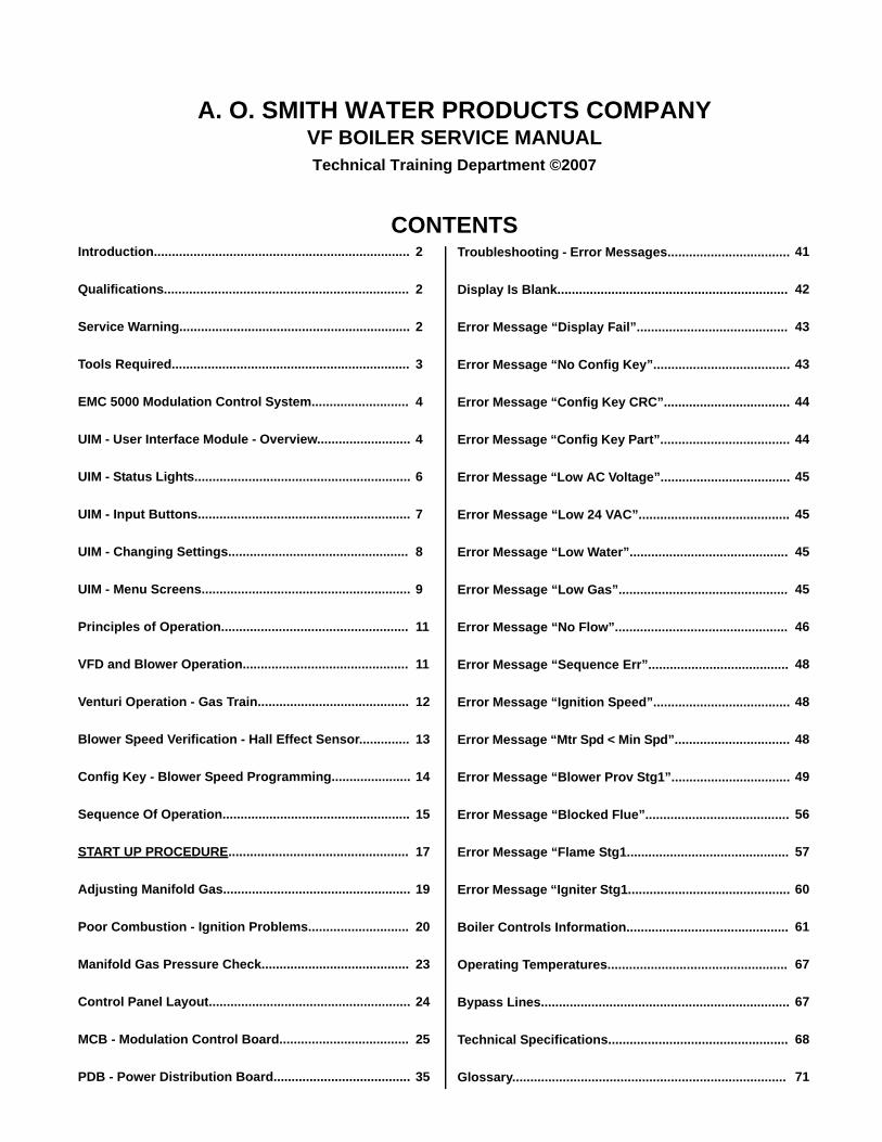
CONTENTSIntroduction.......................................................................
Qualifications....................................................................
Service Warning................................................................
Tools Required..................................................................
EMC 5000 Modulation Control System...........................
UIM - User Interface Module - Overview..........................
UIM - Status Lights............................................................
UIM - Input Buttons...........................................................
UIM - Changing Settings..................................................
UIM - Menu Screens..........................................................
Principles of Operation....................................................
VFD and Blower Operation..............................................
Venturi Operation - Gas Train..........................................
Blower Speed Verification - Hall Effect Sensor..............
Config Key - Blower Speed Programming......................
Sequence Of Operation....................................................
START UP PROCEDURE..................................................
Adjusting Manifold Gas....................................................
Poor Combustion - Ignition Problems............................
Manifold Gas Pressure Check.........................................
Control Panel Layout........................................................
MCB - Modulation Control Board....................................
PDB - Power Distribution Board......................................
2
2
2
3
4
4
6
7
8
9
11
11
12
13
14
15
17
19
20
23
24
25
35
Troubleshooting - Error Messages..................................
Display Is Blank................................................................
Error Message “Display Fail”..........................................
Error Message “No Config Key”......................................
Error Message “Config Key CRC”...................................
Error Message “Config Key Part”....................................
Error Message “Low AC Voltage”....................................
Error Message “Low 24 VAC”..........................................
Error Message “Low Water”............................................
Error Message “Low Gas”...............................................
Error Message “No Flow”................................................
Error Message “Sequence Err”.......................................
Error Message “Ignition Speed”......................................
Error Message “Mtr Spd < Min Spd”................................
Error Message “Blower Prov Stg1”.................................
Error Message “Blocked Flue”........................................
Error Message “Flame Stg1.............................................
Error Message “Igniter Stg1.............................................
Boiler Controls Information.............................................
Operating Temperatures..................................................
Bypass Lines.....................................................................
Technical Specifications..................................................
Glossary............................................................................
41
42
43
43
44
44
45
45
45
45
46
48
48
48
49
56
57
60
61
67
67
68
71
VF BOILER SERVICE MANUAL
INTRODUCTIONThis Service Manual is designed to aid in servicing and troubleshooting A. O. Smith VF boilers. Models VW/VB 500 - 1000 - series 100/101 boilers are covered in this manual.
The instructions and illustrations contained in this service manual will provide you with troubleshooting procedures to verify proper operation and diagnose and repair common service problems.
Important Service ReminderWhen performing any troubleshooting step outlined in this service manual always consider the wiring and connectors between components. Perform a close visual inspection of all wiring and connectors to and from a given component before replacement. Ensure wires were stripped before being crimped in a wire connector, ensure wires are crimped tightly in their connectors, ensure connection pins in sockets and plugs are not damaged or worn, ensure plugs and sockets are mating properly and providing good contact.
Failure to perform this critical step or failing to perform this step thoroughly often results in needless down time, unnecessary parts replacement, and customer dissatisfaction.
Instruction ManualHave a copy of the Instruction Manual that came with the boiler on hand for the model and series number before servicing.
Installation information given in this service manual is not a complete installation instruction. Installation information covered in this service manual has a limited focus as it applies to servicing the boiler. This Service Manual does not replace or supersede the Instruction Manual that came with the boiler. Always refer to the Instruction Manual that came with the boiler for complete installation instructions.
QualificationsService of A. O. Smith VF boilers requires ability equivalent to that of a Qualified Service Agent (defined by ANSI below) in the field involved. Installation skills such as plumbing, air supply, venting, gas supply, electrical supply are required in addition to electrical testing skills. Start up and servicing of VF boilers requires combustion analysis test equipment.
ANSI Z223.1 2006 Sec. 3.3.83: “Qualified Agency” - “Any individual, firm, corporation or company that either in person or through a representative is engaged in and is responsible for (a) the installation, testing or replacement of gas piping or (b) the connection, installation, testing, repair or servicing of appliances and equipment; that is experienced in such work; that is familiar with all precautions required; and that has complied with all the requirements of the authority having jurisdiction.”
Service WarningIf you are not licensed or certified to perform a given task do not attempt to perform any of the service or installation procedures outlined in this manual. If you do not understand the instructions given in this manual or do not feel confident in your abilities to perform a given task do not attempt to perform any procedures outlined in this manual.
AOS WPC - Tech Training 2 of 72 Ashland City, TN © 2007Servicing should only be performed by a Qualified Service Agent
VF BOILER SERVICE MANUAL
Tools Required• Instruction Manual that came with the boiler.
• Hand tools common to installation and service of commercial water heaters and boilers.
• TORX® T40 or 5mm hex wrench - for setting gas mixture at gas valve.
• 3mm or 7/64in hex (allen) wrench - for setting gas mixture at gas valve.
• Two - U tube manometers (preferably) or gas pressure gauges. U tube manometers can be used to accurately measure supply gas pressures. However, their resolution is insufficient to be used for measuring draft, manifold gas pressure on VF boilers, or perform air pressure switch testing. U tube manometers or gas pressure gauges may not be substituted for Digital Manometers listed below.
• Digital Manometer (s) range -20.00 to +20.00" W.C., resolution 0.01" W.C. Recommend UEI model EM200 or equivalent. Used to test performance of air pressure switches, measure draft, and measure manifold gas pressure.
• True RMS Digital Multi Meter DMM, recommend UEI model DL289 or Fluke equivalent.Capable of measuring:
AC/DC VoltageVAC Frequency (Hz)OhmsDC micro amps µA
• AC amp meter- recommend UEI model DL289 or equivalent.
• Combustion analyzer Capable of measuring:
CO2CODraft PressureExhaust TemperatureEfficiency
AOS WPC - Tech Training 3 of 72 Ashland City, TN © 2007Servicing should only be performed by a Qualified Service Agent
VF BOILER SERVICE MANUAL
EMC 5000 MODULATION CONTROL SYSTEMThis portion of the service manual will cover the EMC 5000 Modulation Control system (EMC - Energy Management Control). The EMC 5000 control system includes several components: a UIM (User Interface Module), a MCB (Modulation Control Board), and a PDB (Power Distribution Board). The EMC 5000 Control System can control single stage, multiple stage, and modulating boilers and water heaters. This service manual should be used as a reference for A. O. Smith VW/VB 500-1000 Series 100-101 boilers only.
Features Include:• EMI / RFI filtering - built into all circuit boards. (EMI = Electro Magnetic Interference, RFI
= Radio Frequency Interference) Helps prevent or eliminate erratic operation caused by EMI/RFI.
• Help screens - text based operational information to help the user understand how to change settings and navigate the menu screens.
• Self diagnostics - text based diagnostic information (error and fault messages) on board to help service technicians quickly and accurately service the boiler.
• Error message log - will retain a 9 event history (plus the current event) of error messages with a time stamp. This will help diagnose load and/or environmental conditions that may be contributing to a problem with operation or a lock-out.
• Short cycling protection - if any stage logs more than 30 cycles in one hour the control enters a short cycle prevention condition. The boiler will continue to operate in this mode. The UIM will display and log a “Short Cycle Cond” error message with the yellow Standby system status LED flashing. The MCB will add a 180 second delay before activating any stage’s call for heat after the last call for heat during this operating mode.
The short cycle protection mode can be ended (reset) by touching the Select button on the UIM while the error message is displayed.
• Temperature probe filtering - The inlet, outlet, and remote Tank/Loop temperature probes are read twice per second by the MCB and are filtered for 4 seconds. This filtering will help prevent rapid short cycling caused by momentary fluctuations in temperature.
• Pressure/flow switch filtering - input switches such as air pressure switches are read every second by the MCB and are filtered (de-bounced) for 6 seconds. This desensitizes the input signal and will help prevent nuisance error/fault conditions due to momentary fluctuations caused by wind gusts or blower speed changes. The flow switch is filtered for 4 seconds.
• Network capability - multiple boilers can be networked together (daisy chained) with standard Category 5/6 network cable and given individual network addresses.
• Access/monitoring with future A. O. Smith EMS (Energy Management System) controller.
AOS WPC - Tech Training 4 of 72 Ashland City, TN © 2007Servicing should only be performed by a Qualified Service Agent
VF BOILER SERVICE MANUAL
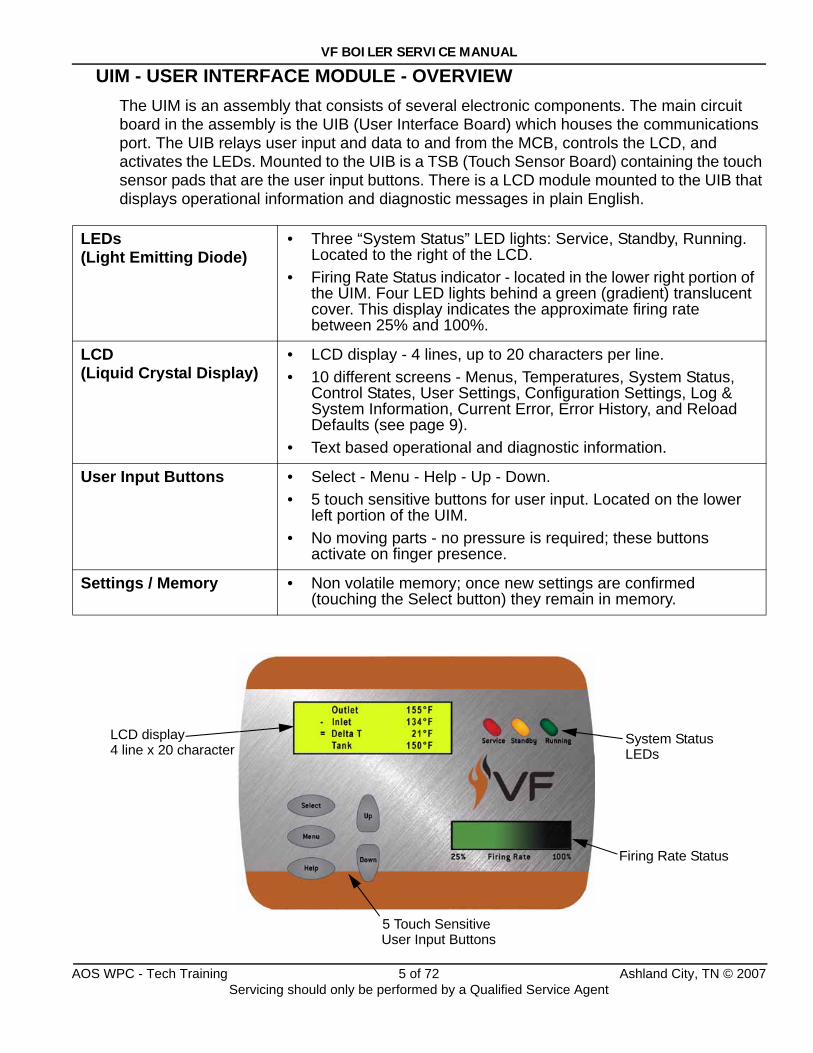
UIM - USER INTERFACE MODULE - OVERVIEWThe UIM is an assembly that consists of several electronic components. The main circuit board in the assembly is the UIB (User Interface Board) which houses the communications port. The UIB relays user input and data to and from the MCB, controls the LCD, and activates the LEDs. Mounted to the UIB is a TSB (Touch Sensor Board) containing the touch sensor pads that are the user input buttons. There is a LCD module mounted to the UIB that displays operational information and diagnostic messages in plain English.
LEDs(Light Emitting Diode)
• Three “System Status” LED lights: Service, Standby, Running. Located to the right of the LCD.
• Firing Rate Status indicator - located in the lower right portion of the UIM. Four LED lights behind a green (gradient) translucent cover. This display indicates the approximate firing rate between 25% and 100%.
LCD(Liquid Crystal Display)
• LCD display - 4 lines, up to 20 characters per line.• 10 different screens - Menus, Temperatures, System Status,
Control States, User Settings, Configuration Settings, Log & System Information, Current Error, Error History, and Reload Defaults (see page 9).
• Text based operational and diagnostic information.
User Input Buttons • Select - Menu - Help - Up - Down.• 5 touch sensitive buttons for user input. Located on the lower
left portion of the UIM.• No moving parts - no pressure is required; these buttons
activate on finger presence.
Settings / Memory • Non volatile memory; once new settings are confirmed (touching the Select button) they remain in memory.
LCD display4 line x 20 character
Firing Rate Status
5 Touch SensitiveUser Input Buttons
System Status LEDs
AOS WPC - Tech Training 5 of 72 Ashland City, TN © 2007Servicing should only be performed by a Qualified Service Agent
VF BOILER SERVICE MANUAL
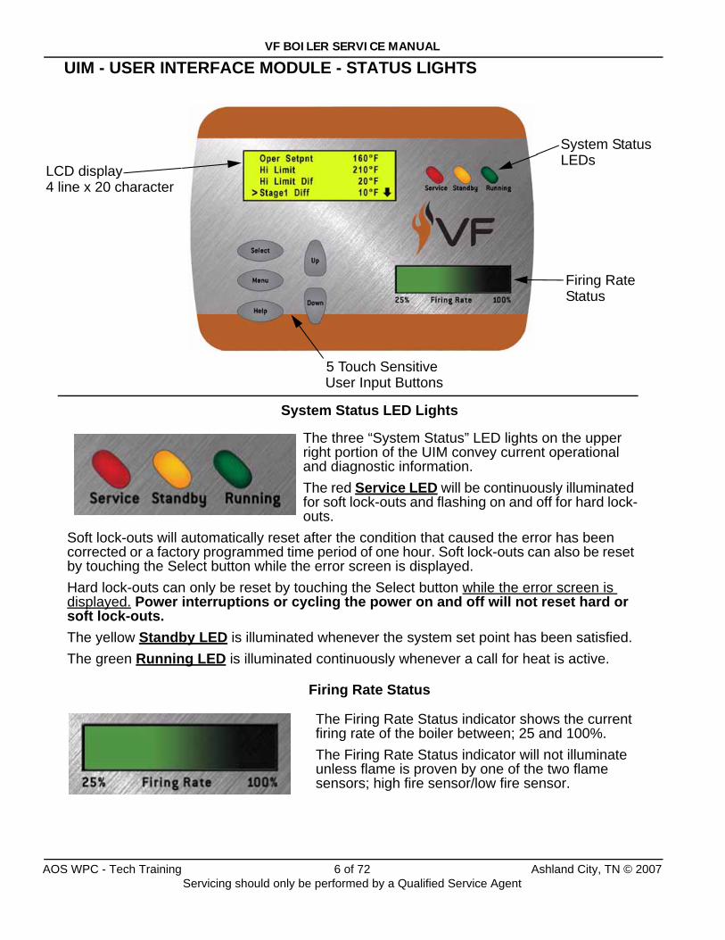
UIM - USER INTERFACE MODULE - STATUS LIGHTS
LCD display4 line x 20 character
System Status
Firing Rate
LEDs
5 Touch SensitiveUser Input Buttons
System Status LED Lights
Firing Rate Status
The three “System Status” LED lights on the upper right portion of the UIM convey current operational and diagnostic information. The red Service LED will be continuously illuminated for soft lock-outs and flashing on and off for hard lock-outs.
Soft lock-outs will automatically reset after the condition that caused the error has been corrected or a factory programmed time period of one hour. Soft lock-outs can also be reset by touching the Select button while the error screen is displayed. Hard lock-outs can only be reset by touching the Select button while the error screen is displayed. Power interruptions or cycling the power on and off will not reset hard or soft lock-outs.The yellow Standby LED is illuminated whenever the system set point has been satisfied.The green Running LED is illuminated continuously whenever a call for heat is active.
The Firing Rate Status indicator shows the current firing rate of the boiler between; 25 and 100%. The Firing Rate Status indicator will not illuminate unless flame is proven by one of the two flame sensors; high fire sensor/low fire sensor.
Status
AOS WPC - Tech Training 6 of 72 Ashland City, TN © 2007Servicing should only be performed by a Qualified Service Agent
VF BOILER SERVICE MANUAL
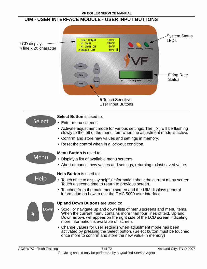
UIM - USER INTERFACE MODULE - USER INPUT BUTTONS
Select Button is used to:• Enter menu screens.• Activate adjustment mode for various settings. The [ > ] will be flashing
slowly to the left of the menu item when the adjustment mode is active.• Confirm and store new values and settings in memory.• Reset the control when in a lock-out condition.
Menu Button is used to:• Display a list of available menu screens.• Abort or cancel new values and settings, returning to last saved value.
Help Button is used to:• Touch once to display helpful information about the current menu screen.
Touch a second time to return to previous screen.• Touched from the main menu screen and the UIM displays general
information on how to use the EMC 5000 user interface.
Up and Down Buttons are used to:• Scroll or navigate up and down lists of menu screens and menu items.
When the current menu contains more than four lines of text, Up and Down arrows will appear on the right side of the LCD screen indicating more information is available off screen.
• Change values for user settings when adjustment mode has been activated by pressing the Select button. (Select button must be touched once more to confirm and store the new value in memory)
LCD display4 line x 20 character
System Status
Firing Rate
LEDs
5 Touch SensitiveUser Input Buttons
Status
AOS WPC - Tech Training 7 of 72 Ashland City, TN © 2007Servicing should only be performed by a Qualified Service Agent
VF BOILER SERVICE MANUAL
UIM - USER INTERFACE MODULE - CHANGING SETTINGS
1
2
3
4
5
6
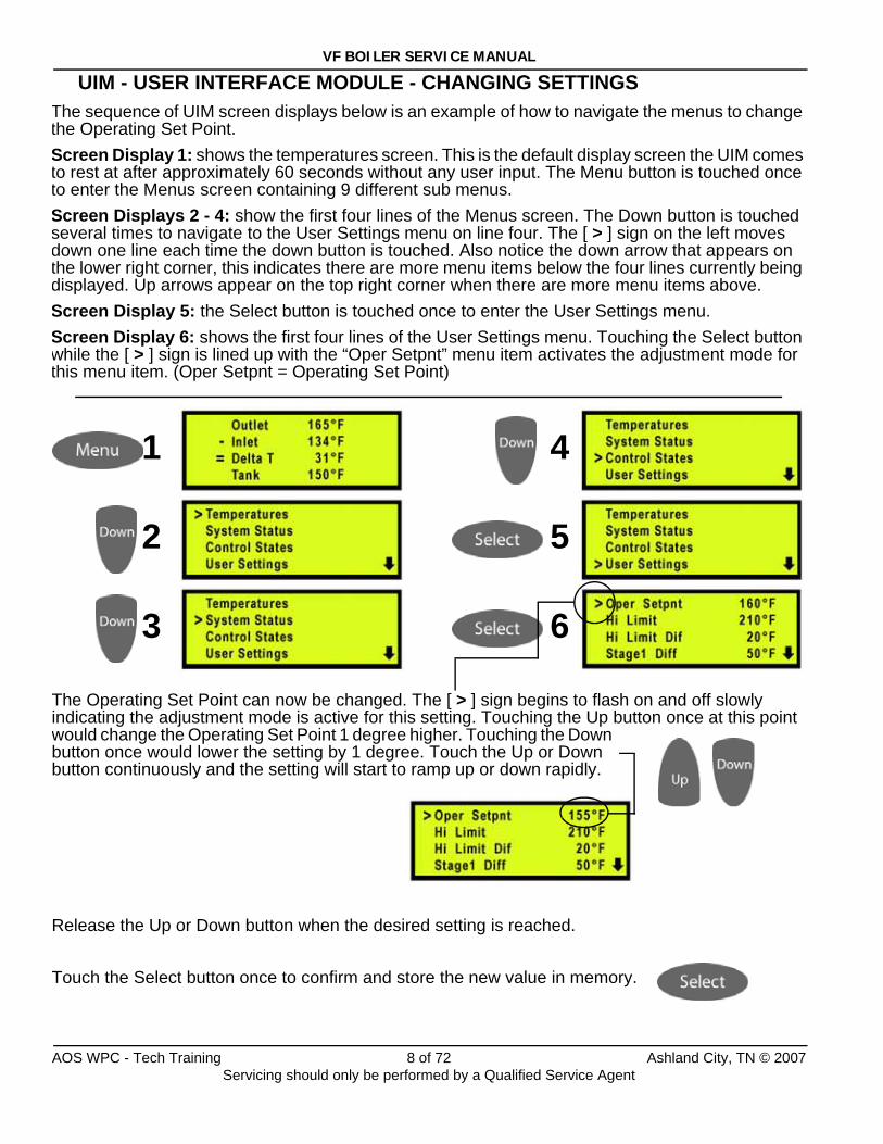
The sequence of UIM screen displays below is an example of how to navigate the menus to change the Operating Set Point.Screen Display 1: shows the temperatures screen. This is the default display screen the UIM comes to rest at after approximately 60 seconds without any user input. The Menu button is touched once to enter the Menus screen containing 9 different sub menus. Screen Displays 2 - 4: show the first four lines of the Menus screen. The Down button is touched several times to navigate to the User Settings menu on line four. The [ > ] sign on the left moves down one line each time the down button is touched. Also notice the down arrow that appears on the lower right corner, this indicates there are more menu items below the four lines currently being displayed. Up arrows appear on the top right corner when there are more menu items above.Screen Display 5: the Select button is touched once to enter the User Settings menu. Screen Display 6: shows the first four lines of the User Settings menu. Touching the Select button while the [ > ] sign is lined up with the “Oper Setpnt” menu item activates the adjustment mode for this menu item. (Oper Setpnt = Operating Set Point)
The Operating Set Point can now be changed. The [ > ] sign begins to flash on and off slowly indicating the adjustment mode is active for this setting. Touching the Up button once at this point would change the Operating Set Point 1 degree higher. Touching the Down button once would lower the setting by 1 degree. Touch the Up or Down button continuously and the setting will start to ramp up or down rapidly.
Release the Up or Down button when the desired setting is reached.
Touch the Select button once to confirm and store the new value in memory.
AOS WPC - Tech Training 8 of 72 Ashland City, TN © 2007Servicing should only be performed by a Qualified Service Agent
VF BOILER SERVICE MANUAL
UIM - USER INTERFACE MODULE - MENU SCREENSAt the top center of the UIM panel is the display LCD. This LCD is used to provide information to the user through menu activated screens. Within each of the screens, helpful context sensitive information can be displayed at any time by touching the “Help” button. Touching the help button once more returns the user to the previous screen.
The 10 available screens are:
Menu Screen:Displayed when the “Menu” button is touched. This screen is the selection point for the other menu screens.
Temperatures Screen (Default Screen):Displays the temperatures sensed from the Outlet, Inlet, and optional remote Tank/Loop temperature probes. This screen also displays the calculated temperature rise (Outlet minus Inlet) through the boiler, sometimes referred to as the Delta T (ΔT). Shorted and disconnected probes will have “Short” and “----” displayed to the right. The Temperatures Screen is the default screen the boiler will come to rest at without any user input for approximately 60 seconds.
There are no adjustable user inputs available from this screen.
System Status Screen:This screen is used to view the status of switch inputs and output states. An asterisk (*) is displayed next to the label when the status is “True” (the description is fulfilled). For example; if water is flowing, as detected by the flow switch, an asterisk (*) will appear in front of the Flow label (IE: *Flow).
There are no adjustable user inputs available from this screen.
Control States Screen:The CCB/FCB operating states of the boiler are displayed in this menu screen along with the actual blower motor rpm as relayed from a Hall Effect sensor (page 13) located inside the end cap of the blower motor. Blower rpm are displayed in real time. CCB and MCB are the same component on VF Boilers. See explanation for this and the FCB term on page 25.
There are no adjustable user inputs available from this screen.
User Settings Screen:This screen is used to enter values for various user settings such as; the operating set point abbreviated Oper Setpnt, the Hi Limit (automatic high limit), pump post circulate time etc. The Select button must be touched once to activate the adjustment mode for a user setting and again to confirm and store the new setting into memory.
Configuration Settings ScreenDisplays the status of the SW1 and SW2 dip switches (pages 30 and 33) on the MCB.
There are no adjustable user inputs available from this screen.
AOS WPC - Tech Training 9 of 72 Ashland City, TN © 2007Servicing should only be performed by a Qualified Service Agent
VF BOILER SERVICE MANUAL
UIM - USER INTERFACE MODULE - MENUS
Log & System Info Screen:This screen displays the following:
• Elapsed hours of operation (Total time system has been powered up).
• Number of running minutes (Number of minutes system has been in the run mode).
• Number of heating cycles.
• kBtu rating of the boiler.
• Software revision of the CCB (MCB), FCB, and Config Key (see explanation on page 25).
There are no adjustable user inputs available from this screen.
Current Error Screen: Displays the current error the system has detected, plus a timestamp of when the error occurred. (The timestamp is based on the elapsed hours value at the time the error occurred. It is displayed in hours and minutes). This error remains displayed as long as it is still valid. When cleared it is moved to the Error History Screen. The system will automatically jump to this screen when an error is detected. It will also go to this screen upon power-up if an error was still valid when power was turned off.
Errors are cleared (control system is reset) from this screen by touching the Select button.
There are no adjustable user inputs available from this screen.
Error History Screen:This screen displays a list of the last 9 errors (with timestamps) that have occurred. The last error to occur is displayed first. The actual date and time of the event can be calculated by subtracting the error time stamp from the elapsed hours of operation in the Log & System Info Screen. This can be helpful when determining if the error is related to environmental or load conditions.
There are no adjustable user inputs available from this screen.
Reload Defaults Screen:From this screen the user can restore the factory default values for screen adjustable configurations by touching the Select button. See page 70 for default values.
AOS WPC - Tech Training 10 of 72 Ashland City, TN © 2007Servicing should only be performed by a Qualified Service Agent
VF BOILER SERVICE MANUAL
PRINCIPLES OF OPERATIONVF boilers do not have a gas orifice. The blower “pulls” gas from the gas valve into a Venturi attached to the suction (inlet) side of the blower (page 12). As the speed of the blower is increased the vacuum in the Venturi is also increased and more fuel gas and combustion air is supplied to the burner. This is the basic principle of how a VF boiler modulates firing rate.
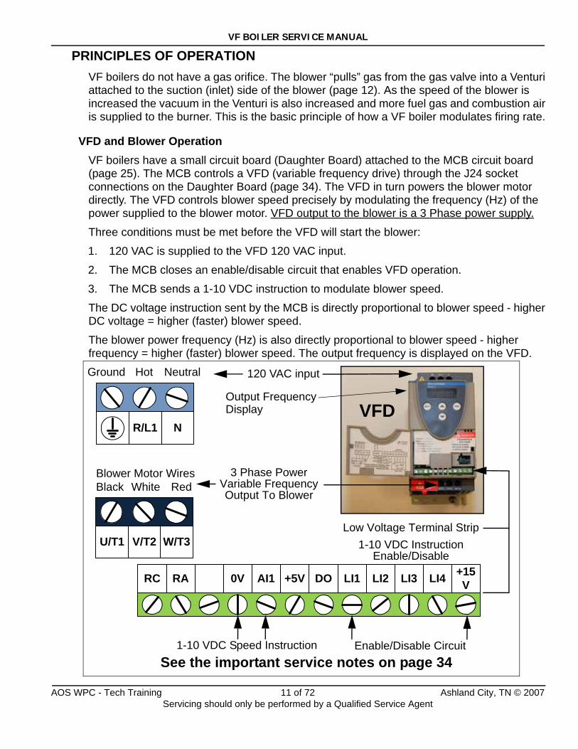
VFD and Blower OperationVF boilers have a small circuit board (Daughter Board) attached to the MCB circuit board (page 25). The MCB controls a VFD (variable frequency drive) through the J24 socket connections on the Daughter Board (page 34). The VFD in turn powers the blower motor directly. The VFD controls blower speed precisely by modulating the frequency (Hz) of the power supplied to the blower motor. VFD output to the blower is a 3 Phase power supply.
Three conditions must be met before the VFD will start the blower:
1. 120 VAC is supplied to the VFD 120 VAC input.
2. The MCB closes an enable/disable circuit that enables VFD operation.
3. The MCB sends a 1-10 VDC instruction to modulate blower speed.
The DC voltage instruction sent by the MCB is directly proportional to blower speed - higher DC voltage = higher (faster) blower speed.
The blower power frequency (Hz) is also directly proportional to blower speed - higher frequency = higher (faster) blower speed. The output frequency is displayed on the VFD.
120 VAC input
Low Voltage Terminal Strip1-10 VDC Instruction
Enable/DisableW/T3V/T2U/T1
NR/L1
RARC +5VAI10V LI2LI1DO +15VLI4LI3
3 Phase PowerVariable FrequencyOutput To Blower
Ground Hot Neutral
Black White RedBlower Motor Wires
VFD
1-10 VDC Speed Instruction Enable/Disable CircuitSee the important service notes on page 34
Output FrequencyDisplay
AOS WPC - Tech Training 11 of 72 Ashland City, TN © 2007Servicing should only be performed by a Qualified Service Agent
VF BOILER SERVICE MANUAL
PRINCIPLE OF OPERATION (CONT)
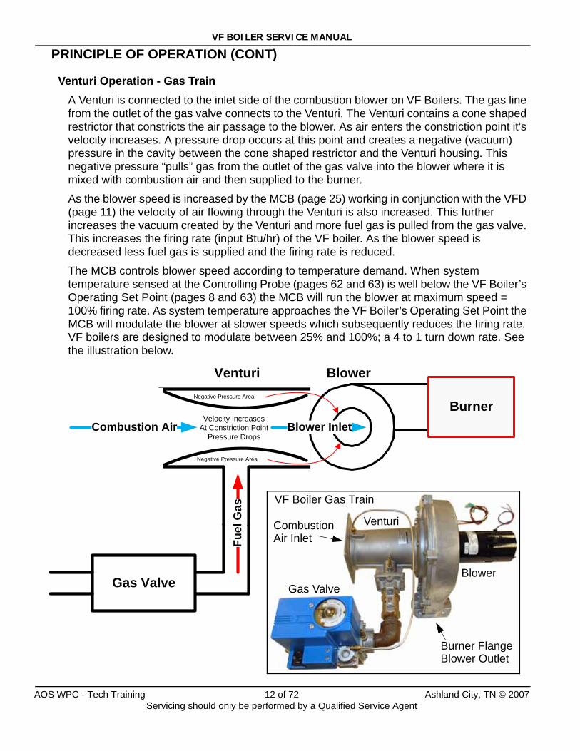
Venturi Operation - Gas TrainA Venturi is connected to the inlet side of the combustion blower on VF Boilers. The gas line from the outlet of the gas valve connects to the Venturi. The Venturi contains a cone shaped restrictor that constricts the air passage to the blower. As air enters the constriction point it’s velocity increases. A pressure drop occurs at this point and creates a negative (vacuum) pressure in the cavity between the cone shaped restrictor and the Venturi housing. This negative pressure “pulls” gas from the outlet of the gas valve into the blower where it is mixed with combustion air and then supplied to the burner.
As the blower speed is increased by the MCB (page 25) working in conjunction with the VFD (page 11) the velocity of air flowing through the Venturi is also increased. This further increases the vacuum created by the Venturi and more fuel gas is pulled from the gas valve. This increases the firing rate (input Btu/hr) of the VF boiler. As the blower speed is decreased less fuel gas is supplied and the firing rate is reduced.
The MCB controls blower speed according to temperature demand. When system temperature sensed at the Controlling Probe (pages 62 and 63) is well below the VF Boiler’s Operating Set Point (pages 8 and 63) the MCB will run the blower at maximum speed = 100% firing rate. As system temperature approaches the VF Boiler’s Operating Set Point the MCB will modulate the blower at slower speeds which subsequently reduces the firing rate. VF boilers are designed to modulate between 25% and 100%; a 4 to 1 turn down rate. See the illustration below.
Combustion Air
Fuel
Gas
Velocity IncreasesAt Constriction Point
Pressure Drops
Negative Pressure Area
Negative Pressure Area
Gas Valve
Venturi Blower
BurnerBlower Inlet
Gas Valve
Venturi
Blower
Burner Flange
CombustionAir Inlet
VF Boiler Gas Train
Blower Outlet
AOS WPC - Tech Training 12 of 72 Ashland City, TN © 2007Servicing should only be performed by a Qualified Service Agent
VF BOILER SERVICE MANUAL
PRINCIPLE OF OPERATION (CONT)
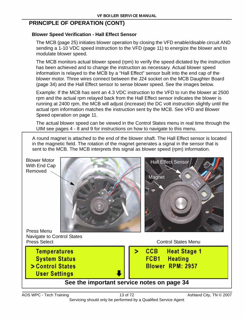
Blower Speed Verification - Hall Effect SensorThe MCB (page 25) initiates blower operation by closing the VFD enable/disable circuit AND sending a 1-10 VDC speed instruction to the VFD (page 11) to energize the blower and to modulate blower speed.
The MCB monitors actual blower speed (rpm) to verify the speed dictated by the instruction has been achieved and to change the instruction as necessary. Actual blower speed information is relayed to the MCB by a “Hall Effect” sensor built into the end cap of the blower motor. Three wires connect between the J24 socket on the MCB Daughter Board (page 34) and the Hall Effect sensor to sense blower speed. See the images below.
Example: If the MCB has sent an 4.3 VDC instruction to the VFD to run the blower at 2500 rpm and the actual rpm relayed back from the Hall Effect sensor indicates the blower is running at 2400 rpm, the MCB will adjust (increase) the DC volt instruction slightly until the actual rpm information matches the instruction sent by the MCB. See VFD and Blower Speed operation on page 11.
The actual blower speed can be viewed in the Control States menu in real time through the UIM see pages 4 - 8 and 9 for instructions on how to navigate to this menu.
Control States Menu
A round magnet is attached to the end of the blower shaft. The Hall Effect sensor is locatedin the magnetic field. The rotation of the magnet generates a signal in the sensor that issent to the MCB. The MCB interprets this signal as blower speed (rpm) information.
Magnet
Hall Effect SensorBlower MotorWith End CapRemoved
See the important service notes on page 34
Press MenuNavigate to Control StatesPress Select
AOS WPC - Tech Training 13 of 72 Ashland City, TN © 2007Servicing should only be performed by a Qualified Service Agent
VF BOILER SERVICE MANUAL
PRINCIPLE OF OPERATION (CONT)
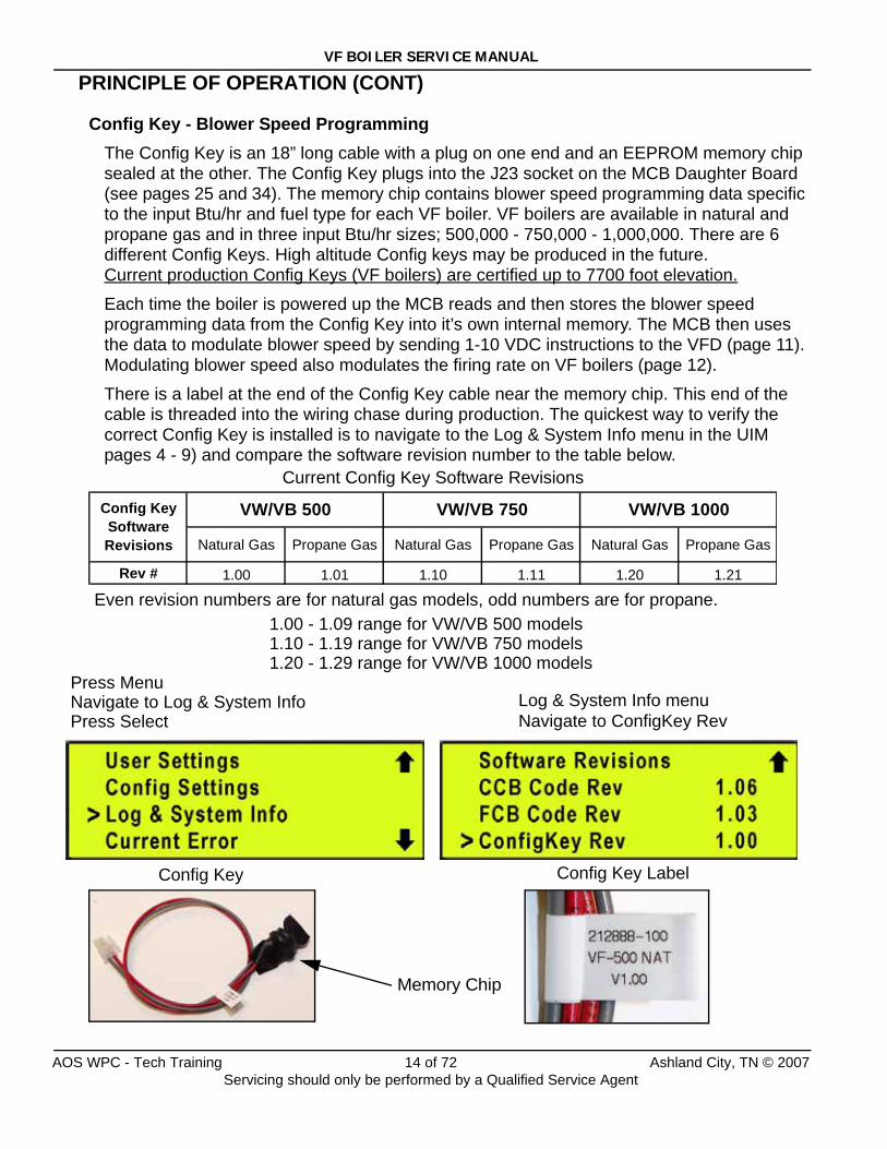
Config Key - Blower Speed ProgrammingThe Config Key is an 18” long cable with a plug on one end and an EEPROM memory chip sealed at the other. The Config Key plugs into the J23 socket on the MCB Daughter Board (see pages 25 and 34). The memory chip contains blower speed programming data specific to the input Btu/hr and fuel type for each VF boiler. VF boilers are available in natural and propane gas and in three input Btu/hr sizes; 500,000 - 750,000 - 1,000,000. There are 6 different Config Keys. High altitude Config keys may be produced in the future. Current production Config Keys (VF boilers) are certified up to 7700 foot elevation.
Each time the boiler is powered up the MCB reads and then stores the blower speed programming data from the Config Key into it’s own internal memory. The MCB then uses the data to modulate blower speed by sending 1-10 VDC instructions to the VFD (page 11). Modulating blower speed also modulates the firing rate on VF boilers (page 12).
There is a label at the end of the Config Key cable near the memory chip. This end of the cable is threaded into the wiring chase during production. The quickest way to verify the correct Config Key is installed is to navigate to the Log & System Info menu in the UIM pages 4 - 9) and compare the software revision number to the table below.
Memory Chip
Natural Gas Propane Gas Natural Gas Propane Gas Natural Gas Propane Gas
Rev # 1.00 1.01 1.10 1.11 1.20 1.21
Config Key Software Revisions
VW/VB 500 VW/VB 750 VW/VB 1000
Log & System Info menu
Config Key Label
Current Config Key Software Revisions
Even revision numbers are for natural gas models, odd numbers are for propane.1.00 - 1.09 range for VW/VB 500 models1.10 - 1.19 range for VW/VB 750 models1.20 - 1.29 range for VW/VB 1000 models
Config Key
Press MenuNavigate to Log & System InfoPress Select Navigate to ConfigKey Rev
AOS WPC - Tech Training 14 of 72 Ashland City, TN © 2007Servicing should only be performed by a Qualified Service Agent
VF BOILER SERVICE MANUAL
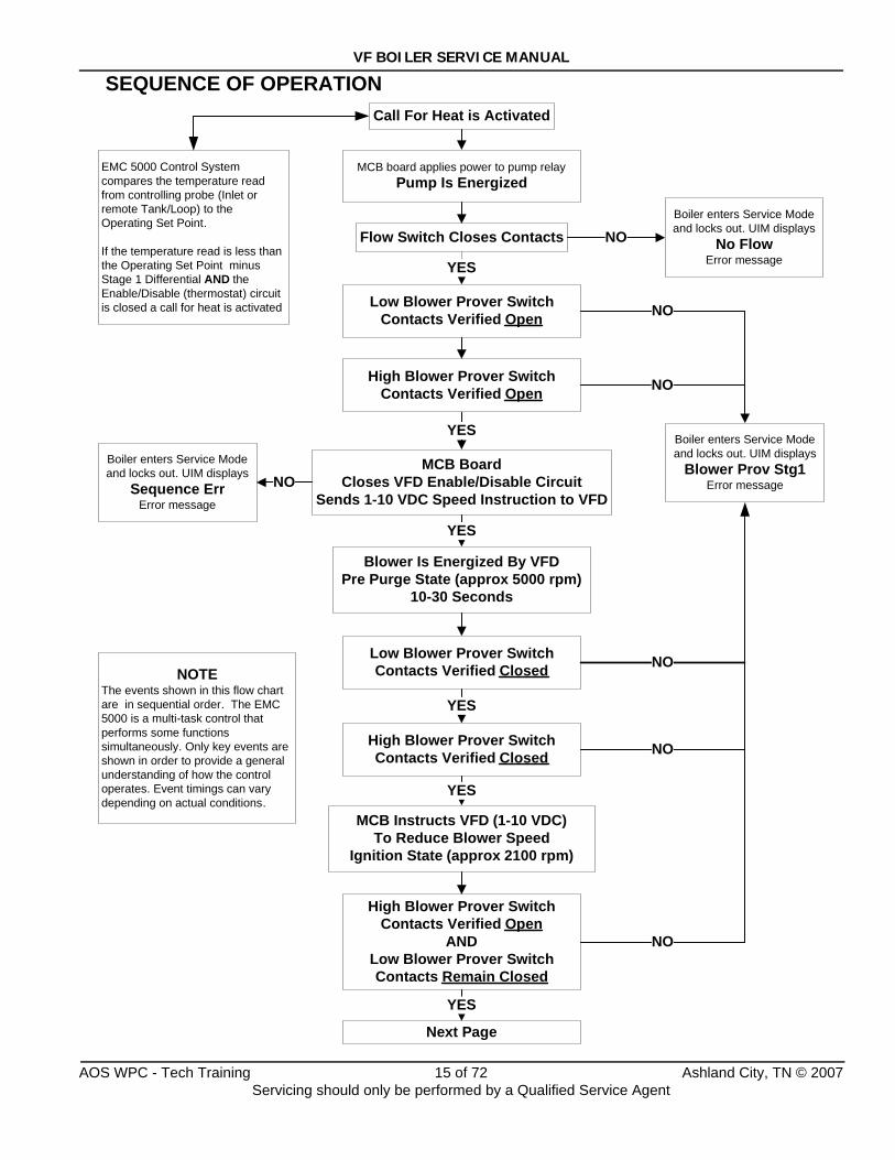
SEQUENCE OF OPERATION
MCB board applies power to pump relayPump Is Energized
Flow Switch Closes Contacts NOBoiler enters Service Mode and locks out. UIM displays
No FlowError message
MCB BoardCloses VFD Enable/Disable Circuit
Sends 1-10 VDC Speed Instruction to VFD
Low Blower Prover SwitchContacts Verified Open
YES
YES
NO
EMC 5000 Control System compares the temperature read from controlling probe (Inlet or remote Tank/Loop) to the Operating Set Point.
If the temperature read is less than the Operating Set Point minus Stage 1 Differential AND the Enable/Disable (thermostat) circuit is closed a call for heat is activated
Call For Heat is Activated
High Blower Prover SwitchContacts Verified Open
Boiler enters Service Mode and locks out. UIM displays
Blower Prov Stg1Error message
NO
Blower Is Energized By VFDPre Purge State (approx 5000 rpm)
10-30 Seconds
Low Blower Prover SwitchContacts Verified Closed
High Blower Prover SwitchContacts Verified Closed
Boiler enters Service Mode and locks out. UIM displays
Sequence ErrError message
YES
YES
NO
NO
MCB Instructs VFD (1-10 VDC)To Reduce Blower Speed
Ignition State (approx 2100 rpm)
High Blower Prover SwitchContacts Verified Open
ANDLow Blower Prover Switch Contacts Remain Closed
YES
YES
Next Page
NO
NOTEThe events shown in this flow chart are in sequential order. The EMC 5000 is a multi-task control that performs some functions simultaneously. Only key events are shown in order to provide a general understanding of how the control operates. Event timings can vary depending on actual conditions.
NO
AOS WPC - Tech Training 15 of 72 Ashland City, TN © 2007Servicing should only be performed by a Qualified Service Agent
VF BOILER SERVICE MANUAL
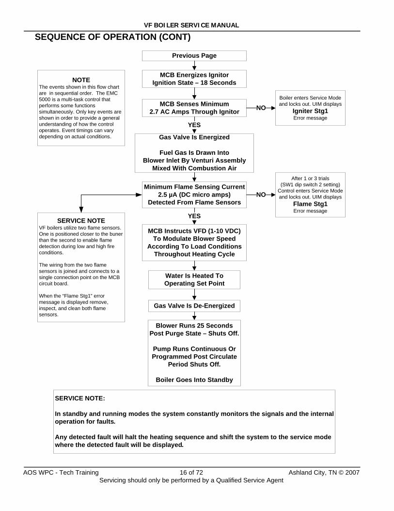
SEQUENCE OF OPERATION (CONT)
MCB Senses Minimum2.7 AC Amps Through Ignitor
Gas Valve Is Energized
Fuel Gas Is Drawn Into Blower Inlet By Venturi Assembly
Mixed With Combustion Air
Boiler enters Service Mode and locks out. UIM displays
Igniter Stg1Error message
Minimum Flame Sensing Current2.5 µA (DC micro amps)
Detected From Flame Sensors
Water Is Heated To Operating Set Point
Blower Runs 25 Seconds Post Purge State – Shuts Off.
Pump Runs Continuous Or Programmed Post Circulate
Period Shuts Off.
Boiler Goes Into Standby
MCB Energizes IgnitorIgnition State – 18 Seconds
Previous Page
NOTEThe events shown in this flow chart are in sequential order. The EMC 5000 is a multi-task control that performs some functions simultaneously. Only key events are shown in order to provide a general understanding of how the control operates. Event timings can vary depending on actual conditions.
SERVICE NOTEVF boilers utilize two flame sensors. One is positioned closer to the buner than the second to enable flame detection during low and high fire conditions.
The wiring from the two flame sensors is joined and connects to a single connection point on the MCB circuit board.
When the “Flame Stg1” error message is displayed remove, inspect, and clean both flame sensors.
YES
NO
SERVICE NOTE:
In standby and running modes the system constantly monitors the signals and the internal operation for faults.
Any detected fault will halt the heating sequence and shift the system to the service mode where the detected fault will be displayed.
After 1 or 3 trials (SW1 dip switch 2 setting)
Control enters Service Mode and locks out. UIM displays
Flame Stg1Error message
NO
Gas Valve Is De-Energized
MCB Instructs VFD (1-10 VDC)To Modulate Blower Speed
According To Load ConditionsThroughout Heating Cycle
YES
AOS WPC - Tech Training 16 of 72 Ashland City, TN © 2007Servicing should only be performed by a Qualified Service Agent
VF BOILER SERVICE MANUAL
START UP PROCEDURE
Prior To Start UpIn addition to normal supplies and hand tools necessary for installing and servicing water heaters and boilers the following tools and test equipment should be on hand. See the tool requirements page 3.
• A combustion analyzer capable of measuring draft pressure, CO, and CO2 or O2.
• True RMS Digital Multi Meter DMM capable of reading AC volts, DC volts, ohms, DC micro amps µA, and frequency Hz.
• AC amp meter.
• TORX® T40 or 5mm hex wrench - for setting gas mixture at gas valve.
• 3mm or 7/64in hex (allen) wrench - for setting gas mixture at gas valve.
• A U-tube manometer or pressure gauge for measuring supply gas pressure.
• A digital manometer for measuring (negative/vacuum) manifold gas pressure.
Firing Modes - Min/Max/Mod When performing a Start Up on a VF boiler, the boiler’s firing mode must be set to the Min Mode (minimum firing - 25%) and the Max Mode (maximum firing - 100%). While the boiler is firing press the Menu button on the UIM (page 7). Using the Up and Down buttons scroll down until the > cursor to the left of the display is lined up with the User Settings menu and press the Select button. Scroll down to Mod Mode menu item and press the Select button again. The > cursor starts flashing on and off slowly indicating adjustment of this menu item is now possible. Use the up and down buttons to select between these three options:
• Min (forced minimum firing rate - 25%)
• Max (forced maximum firing rate - 100%)
• Mod (MCB automatic controlled firing rate - modulation mode)
Press the Select button for the desired option to confirm. The > cursor stops flashing and the boiler enters the firing mode selected.
The Min Mode and Max Mode are used for checking combustion during start up. Return the boiler to the Mod Mode after checking combustion. The boiler will automatically return to the Mod Mode after 10 minutes. Review the UIM and Menus information on pages 4 - 10.
Turning The Boiler OffNEVER TURN THE BOILER OFF BY SECURING POWER WHILE IT IS FIRING. Repeated sudden stops while firing can damage the boiler. To shut down the boiler safely do one of the following so the boiler can go through a normal shut down sequence with post purge cycles:
• Lower the Operating Set Point to it’s lowest setting.
• Lower the set point of any external control in use to it’s lowest setting.
• Open the boiler’s 24 VAC Enable/Disable circuit manually (wires in the junction box on the back of the boiler). Be careful not to let the bare wire ends touch any grounded surface.
AOS WPC - Tech Training 17 of 72 Ashland City, TN © 2007Servicing should only be performed by a Qualified Service Agent
VF BOILER SERVICE MANUAL
START UP PROCEDURE (CONT)
Start Up Procedure1. Before starting the boiler, please review the boilers Instruction Manual supplied with the
boiler. Ensure the water piping, gas line, controls, and venting have been installed per the instruction manual. Further information on water piping and controls is on pages 61 - 67 in this service manual.
2. Ensure the gas train shut off valve (see the image on page 23) in the boiler’s gas train is open.
3. Purge all air from the gas line to the boiler and ensure there are no gas leaks. Ensure the main supply gas valve is open.
4. Be certain that the system is full of water, that all air has been purged from the boiler, storage tank (s), and the water lines. Open both the supply and return water valves to the boiler. Ensure there are no water leaks.
5. Ensure the power supply meets the minimum requirements on page 68 in this manual. Ensure all control wiring (remote Tank/Loop probe - external Enable/Disable control) is run in a dedicated conduit per requirements on page 68.
6. Perform the power supply test outlined on page 40; correct any problems detected.
7. Prior to turning on the gas, proper sequence of most of the system can be verified. Close the manifold gas shut off valve (page 23), start the system and allow it to run through a heating cycle. It should stop when it checks for the flame and declare a fault. This will verify that the pump, flow switch, igniter, VFD (variable frequency drive), gas valve, blower and low/ high blower prover switches are all functioning.
8. Drill a 7/16” hole in the side of the boot tee approximately 8" from back panel to insert the gas analyzer probe. The hole must be sealed upon completion of the start-up.
9. Open the main supply gas valve to the boiler.
10. Turn the boiler’s on/off switch on. Ensure the Operating Set Point is set high enough to activate a call for heat (page 8). If an external control is using the boiler’s Enable/Disable circuit (Aquastat, Boiler Sequencing Controller, EMS) ensure the external controls contacts are closed (page 65). If there is no external control using the boiler’s Enable/Disable circuit ensure the two wires provided for this circuit are wire nutted together in the junction box on the back of the boiler. Review the controls section beginning on page 61 and refer to the wiring diagram on the boiler.
11. Allow the unit to run for at least 15 minutes before proceeding with the combustion analysis. Take a combustion sample and record CO and CO2 or O2 readings.
12. Attach a U tube manometer to supply gas pressure source at the boiler. Measure the supply gas pressure with a U tube manometer with the boiler firing in Max Mode. Set the boiler to Max Mode (Firing Modes - page 17). Ensure a minimum supply gas pressure of 4.0 " W.C. for natural gas or 11.0 " W.C. for propane is present with the boiler firing at 100%. Maximum supply gas pressures are 11.0 " W.C. natural gas and 13.8 " W.C. propane gas. Adjust supply gas pressure at the supply gas regulator as needed to maintain these supply gas pressure requirements.
AOS WPC - Tech Training 18 of 72 Ashland City, TN © 2007Servicing should only be performed by a Qualified Service Agent
VF BOILER SERVICE MANUAL
START UP PROCEDURE (CONT)
Adjusting Manifold Gas13. Set the boiler to Max Mode (Firing Modes - page 17). Check combustion readings using
combustion analyzer. Compare CO2 readings taken to the high fire CO2 table below. If combustion readings are not in accordance with the high fire CO2 table adjust as follows:
Remove the flat, round, blue plastic cap from the top of the boiler’s 24 VAC gas valve. Using a 3mm (7/64”) hex wrench, turn the high fire adjustment screw under the cap counterclockwise to increase or clockwise to decrease gas flow and achieve the desired CO2 level per high fire table below. When desired adjustments are complete, reinstall the cap on the gas valve. CO readings should be less than 200 ppm.
14. Set the boiler to Min Mode (Firing Modes - page 17). Check combustion readings using combustion analyzer. Compare CO2 readings taken to the low fire CO2 table below. If combustion readings are not in accordance with the low fire CO2 table adjust as follows:
Remove the small metal slotted cap near the outlet of the boiler’s 24 VAC gas valve. Using a TORX® T40 or a 5mm hex wrench, carefully turn the low fire adjustment screw under the cap clockwise to increase or counterclockwise to decrease gas flow and achieve the desired CO2 level per low fire table below. When desired adjustments are complete, reinstall the cap on the gas valve. CO readings should be less than 200 ppm.
Start Up Note: There will be a time delay between adjustments on the gas valve and the response of the CO2 measuring instrument. Adjust the settings in small increments and allow the combustion readings to stabilize for at least 3 minutes before readjusting.
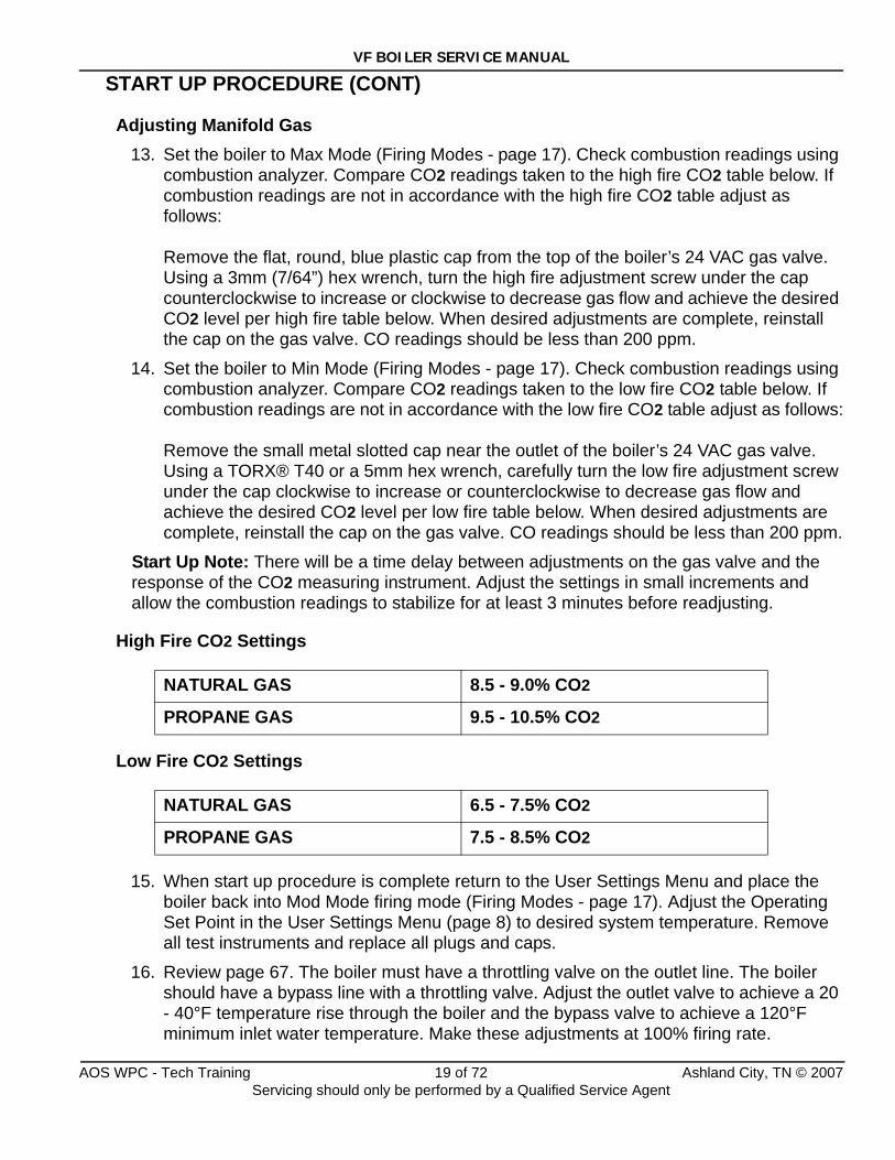
High Fire CO2 Settings
Low Fire CO2 Settings
15. When start up procedure is complete return to the User Settings Menu and place the boiler back into Mod Mode firing mode (Firing Modes - page 17). Adjust the Operating Set Point in the User Settings Menu (page 8) to desired system temperature. Remove all test instruments and replace all plugs and caps.
16. Review page 67. The boiler must have a throttling valve on the outlet line. The boiler should have a bypass line with a throttling valve. Adjust the outlet valve to achieve a 20 - 40°F temperature rise through the boiler and the bypass valve to achieve a 120°F minimum inlet water temperature. Make these adjustments at 100% firing rate.
NATURAL GAS 8.5 - 9.0% CO2
PROPANE GAS 9.5 - 10.5% CO2
NATURAL GAS 6.5 - 7.5% CO2
PROPANE GAS 7.5 - 8.5% CO2
AOS WPC - Tech Training 19 of 72 Ashland City, TN © 2007Servicing should only be performed by a Qualified Service Agent
VF BOILER SERVICE MANUAL
POOR COMBUSTION - IGNITION PROBLEMSIf the high and/or low fire CO2 combustion readings are not in accordance with the tables shown on page 19, the CO readings are high, or if the boiler is experiencing ignition failure or rough starting perform the following procedures:
Adequate Combustion - Proper Venting1. Ensure there is an adequate supply of fresh air for combustion and the boiler is vented
properly. DO NOT OVERLOOK THIS STEP. Lack of combustion air and improper venting is often the root cause for poor combustion.
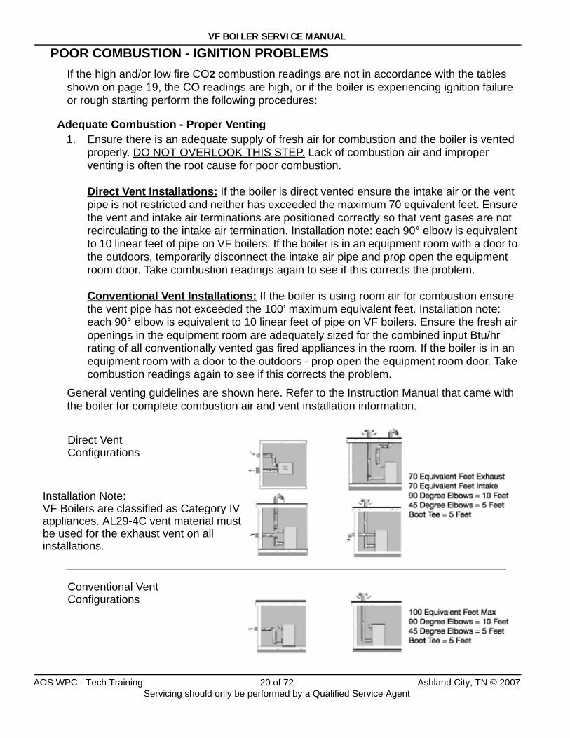
Direct Vent Installations: If the boiler is direct vented ensure the intake air or the vent pipe is not restricted and neither has exceeded the maximum 70 equivalent feet. Ensure the vent and intake air terminations are positioned correctly so that vent gases are not recirculating to the intake air termination. Installation note: each 90° elbow is equivalent to 10 linear feet of pipe on VF boilers. If the boiler is in an equipment room with a door to the outdoors, temporarily disconnect the intake air pipe and prop open the equipment room door. Take combustion readings again to see if this corrects the problem.
Conventional Vent Installations: If the boiler is using room air for combustion ensure the vent pipe has not exceeded the 100’ maximum equivalent feet. Installation note: each 90° elbow is equivalent to 10 linear feet of pipe on VF boilers. Ensure the fresh air openings in the equipment room are adequately sized for the combined input Btu/hr rating of all conventionally vented gas fired appliances in the room. If the boiler is in an equipment room with a door to the outdoors - prop open the equipment room door. Take combustion readings again to see if this corrects the problem.
General venting guidelines are shown here. Refer to the Instruction Manual that came with the boiler for complete combustion air and vent installation information.
Direct VentConfigurations
Conventional VentConfigurations
Installation Note:VF Boilers are classified as Category IVappliances. AL29-4C vent material mustbe used for the exhaust vent on all installations.
AOS WPC - Tech Training 20 of 72 Ashland City, TN © 2007Servicing should only be performed by a Qualified Service Agent
VF BOILER SERVICE MANUAL
POOR COMBUSTION - IGNITION PROBLEMS (CONT)
Burner Inspection2. Remove the burner and inspect the burner for any signs of damage or debris inside. If
the burner is damaged or contaminated with debris - replace the burner. Check all gaskets in the burner/blower assembly for wear or damage. Replace any worn or damaged gaskets.
Firing Rate - Modulation Performance3. The firing rate on VF boilers is modulated or controlled by blower speed (see pages 11
through 14). Ensure the correct Config Key (page 14) is installed for the input Btu/hr rating and fuel type of the boiler you are working on.
4. Verify the blower speed is acceptable during the following three operating states:
• Igniter warm up period - (AC amps can be detected through the igniter).
• Min Mode (Firing Modes - page 17).
• Max Mode (Firing Modes - page 17).
Start the boiler and check the three parameters listed below during the three operating states given above.
• DC voltage sent by the MCB at the VFD (page 11).
• Actual blower rpm as sensed by the Hall Effect sensor (page 13).
• Actual power frequency (Hz) on the VFD display (page 11).
Procedure• Measure the DC volt instruction from the MCB at the VFD to ensure all wiring and
connections between the J24 socket on the MCB Daughter Board and the VFD are intact (page 11).
• Check the actual blower rpm from the Control States Menu via the UIM display (page 13),
• Check the displayed Hz on the VFD (page 11).
Compare these values to those shown in the tables on page 22.
The actual blower rpm displayed by the UIM should be within 20% of the values given in the tables on page 22. The frequency should be within 5% of the values given in the tables page 22. The DC volt instruction should be within 1.0 VDC of the values given in the tables on page 22. If the actual values differ greatly from the values given in the tables on page 22 call our technical information center for further assistance at 800 527-1953.
AOS WPC - Tech Training 21 of 72 Ashland City, TN © 2007Servicing should only be performed by a Qualified Service Agent
VF BOILER SERVICE MANUAL
POOR COMBUSTION - IGNITION PROBLEMS (CONT)
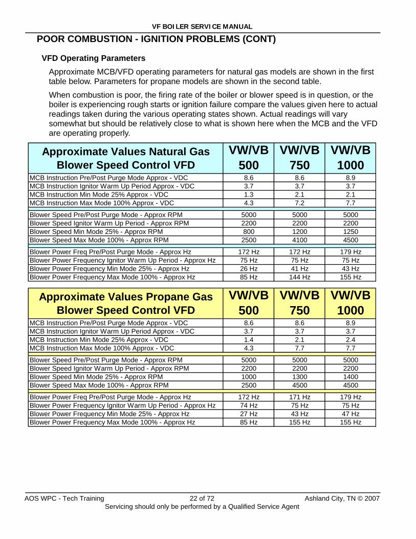
VFD Operating ParametersApproximate MCB/VFD operating parameters for natural gas models are shown in the first table below. Parameters for propane models are shown in the second table.
When combustion is poor, the firing rate of the boiler or blower speed is in question, or the boiler is experiencing rough starts or ignition failure compare the values given here to actual readings taken during the various operating states shown. Actual readings will vary somewhat but should be relatively close to what is shown here when the MCB and the VFD are operating properly.
Approximate Values Natural Gas Blower Speed Control VFD
VW/VB 500
VW/VB 750
VW/VB 1000
MCB Instruction Pre/Post Purge Mode Approx - VDC 8.6 8.6 8.9MCB Instruction Ignitor Warm Up Period Approx - VDC 3.7 3.7 3.7MCB Instruction Min Mode 25% Approx - VDC 1.3 2.1 2.1MCB Instruction Max Mode 100% Approx - VDC 4.3 7.2 7.7
Blower Speed Pre/Post Purge Mode - Approx RPM 5000 5000 5000Blower Speed Ignitor Warm Up Period - Approx RPM 2200 2200 2200Blower Speed Min Mode 25% - Approx RPM 800 1200 1250Blower Speed Max Mode 100% - Approx RPM 2500 4100 4500
Blower Power Freq Pre/Post Purge Mode - Approx Hz 172 Hz 172 Hz 179 HzBlower Power Frequency Ignitor Warm Up Period - Approx Hz 75 Hz 75 Hz 75 HzBlower Power Frequency Min Mode 25% - Approx Hz 26 Hz 41 Hz 43 HzBlower Power Frequency Max Mode 100% - Approx Hz 85 Hz 144 Hz 155 Hz
Approximate Values Propane Gas Blower Speed Control VFD
VW/VB 500
VW/VB 750
VW/VB 1000
MCB Instruction Pre/Post Purge Mode Approx - VDC 8.6 8.6 8.9MCB Instruction Ignitor Warm Up Period Approx - VDC 3.7 3.7 3.7MCB Instruction Min Mode 25% Approx - VDC 1.4 2.1 2.4MCB Instruction Max Mode 100% Approx - VDC 4.3 7.7 7.7
Blower Speed Pre/Post Purge Mode - Approx RPM 5000 5000 5000Blower Speed Ignitor Warm Up Period - Approx RPM 2200 2200 2200Blower Speed Min Mode 25% - Approx RPM 1000 1300 1400Blower Speed Max Mode 100% - Approx RPM 2500 4500 4500
Blower Power Freq Pre/Post Purge Mode - Approx Hz 172 Hz 171 Hz 179 HzBlower Power Frequency Ignitor Warm Up Period - Approx Hz 74 Hz 75 Hz 75 HzBlower Power Frequency Min Mode 25% - Approx Hz 27 Hz 43 Hz 47 HzBlower Power Frequency Max Mode 100% - Approx Hz 85 Hz 155 Hz 155 Hz
AOS WPC - Tech Training 22 of 72 Ashland City, TN © 2007Servicing should only be performed by a Qualified Service Agent
VF BOILER SERVICE MANUAL
POOR COMBUSTION - IGNITION PROBLEMS (CONT)
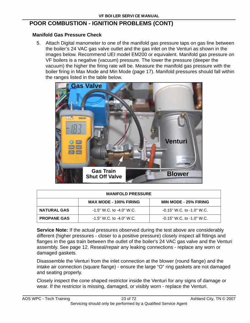
Manifold Gas Pressure Check5. Attach Digital manometer to one of the manifold gas pressure taps on gas line between
the boiler’s 24 VAC gas valve outlet and the gas inlet on the Venturi as shown in the images below. Recommend UEI model EM200 or equivalent. Manifold gas pressure on VF boilers is a negative (vacuum) pressure. The lower the pressure (deeper the vacuum) the higher the firing rate will be. Measure the manifold gas pressure with the boiler firing in Max Mode and Min Mode (page 17). Manifold pressures should fall within the ranges listed in the table below.
Service Note: If the actual pressures observed during the test above are considerably different (higher pressures - closer to a positive pressure) closely inspect all fittings and flanges in the gas train between the outlet of the boiler's 24 VAC gas valve and the Venturi assembly. See page 12. Reseal/repair any leaking connections - replace any worn or damaged gaskets.
Disassemble the Venturi from the inlet connection at the blower (round flange) and the intake air connection (square flange) - ensure the large “O” ring gaskets are not damaged and seating properly.
Closely inspect the cone shaped restrictor inside the Venturi for any signs of damage or wear. If the restrictor is missing, damaged, or visibly worn - replace the Venturi.
MANIFOLD PRESSURE
MAX MODE - 100% FIRING MIN MODE - 25% FIRING
NATURAL GAS -1.5" W.C. to -4.0" W.C. -0.15" W.C. to -1.0" W.C.
PROPANE GAS -1.5" W.C. to -4.0" W.C. -0.15" W.C. to -1.0" W.C.
Venturi
Gas Valve
Gas TrainShut Off Valve Blower
AOS WPC - Tech Training 23 of 72 Ashland City, TN © 2007Servicing should only be performed by a Qualified Service Agent
VF BOILER SERVICE MANUAL
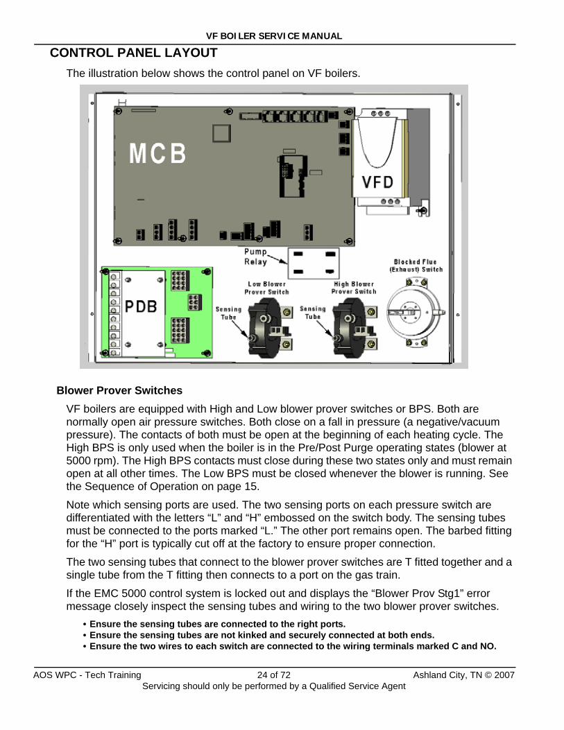
CONTROL PANEL LAYOUTThe illustration below shows the control panel on VF boilers.
Blower Prover SwitchesVF boilers are equipped with High and Low blower prover switches or BPS. Both are normally open air pressure switches. Both close on a fall in pressure (a negative/vacuum pressure). The contacts of both must be open at the beginning of each heating cycle. The High BPS is only used when the boiler is in the Pre/Post Purge operating states (blower at 5000 rpm). The High BPS contacts must close during these two states only and must remain open at all other times. The Low BPS must be closed whenever the blower is running. See the Sequence of Operation on page 15.
Note which sensing ports are used. The two sensing ports on each pressure switch are differentiated with the letters “L” and “H” embossed on the switch body. The sensing tubes must be connected to the ports marked “L.” The other port remains open. The barbed fitting for the “H” port is typically cut off at the factory to ensure proper connection.
The two sensing tubes that connect to the blower prover switches are T fitted together and a single tube from the T fitting then connects to a port on the gas train.
If the EMC 5000 control system is locked out and displays the “Blower Prov Stg1” error message closely inspect the sensing tubes and wiring to the two blower prover switches.
• Ensure the sensing tubes are connected to the right ports.• Ensure the sensing tubes are not kinked and securely connected at both ends.• Ensure the two wires to each switch are connected to the wiring terminals marked C and NO.
AOS WPC - Tech Training 24 of 72 Ashland City, TN © 2007Servicing should only be performed by a Qualified Service Agent
VF BOILER SERVICE MANUAL
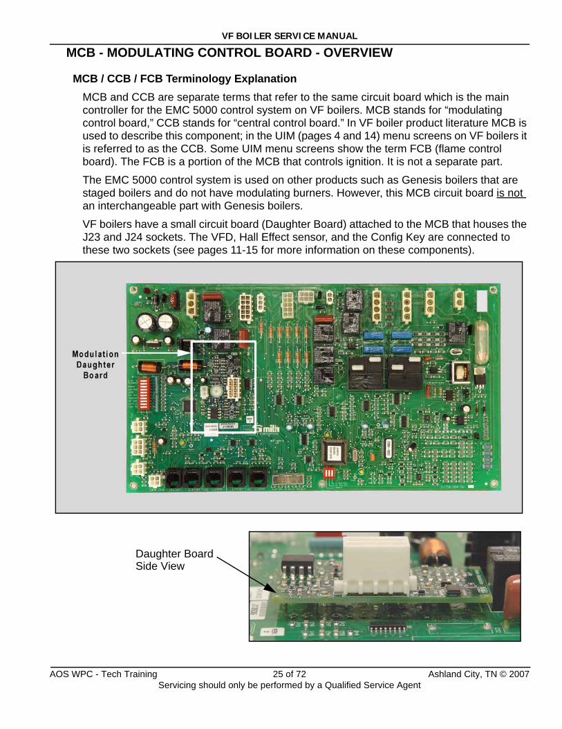
MCB - MODULATING CONTROL BOARD - OVERVIEW
MCB / CCB / FCB Terminology ExplanationMCB and CCB are separate terms that refer to the same circuit board which is the main controller for the EMC 5000 control system on VF boilers. MCB stands for “modulating control board,” CCB stands for “central control board.” In VF boiler product literature MCB is used to describe this component; in the UIM (pages 4 and 14) menu screens on VF boilers it is referred to as the CCB. Some UIM menu screens show the term FCB (flame control board). The FCB is a portion of the MCB that controls ignition. It is not a separate part.
The EMC 5000 control system is used on other products such as Genesis boilers that are staged boilers and do not have modulating burners. However, this MCB circuit board is not an interchangeable part with Genesis boilers.
VF boilers have a small circuit board (Daughter Board) attached to the MCB that houses the J23 and J24 sockets. The VFD, Hall Effect sensor, and the Config Key are connected to these two sockets (see pages 11-15 for more information on these components).
Daughter BoardSide View
AOS WPC - Tech Training 25 of 72 Ashland City, TN © 2007Servicing should only be performed by a Qualified Service Agent
VF BOILER SERVICE MANUAL
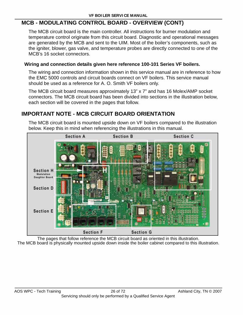
MCB - MODULATING CONTROL BOARD - OVERVIEW (CONT)The MCB circuit board is the main controller. All instructions for burner modulation and temperature control originate from this circuit board. Diagnostic and operational messages are generated by the MCB and sent to the UIM. Most of the boiler’s components, such as the igniter, blower, gas valve, and temperature probes are directly connected to one of the MCB’s 16 socket connectors.
Wiring and connection details given here reference 100-101 Series VF boilers.The wiring and connection information shown in this service manual are in reference to how the EMC 5000 controls and circuit boards connect on VF boilers. This service manual should be used as a reference for A. O. Smith VF boilers only.
The MCB circuit board measures approximately 13” x 7” and has 16 Molex/AMP socket connectors. The MCB circuit board has been divided into sections in the illustration below, each section will be covered in the pages that follow.
IMPORTANT NOTE - MCB CIRCUIT BOARD ORIENTATIONThe MCB circuit board is mounted upside down on VF boilers compared to the illustration below. Keep this in mind when referencing the illustrations in this manual.
The pages that follow reference the MCB circuit board as oriented in this illustration. The MCB board is physically mounted upside down inside the boiler cabinet compared to this illustration.
AOS WPC - Tech Training 26 of 72 Ashland City, TN © 2007Servicing should only be performed by a Qualified Service Agent
VF BOILER SERVICE MANUAL
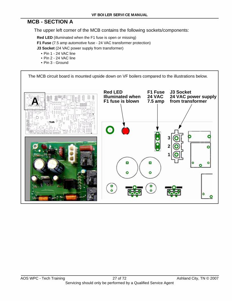
MCB - SECTION AThe upper left corner of the MCB contains the following sockets/components:
Red LED (illuminated when the F1 fuse is open or missing)F1 Fuse (7.5 amp automotive fuse - 24 VAC transformer protection)J3 Socket (24 VAC power supply from transformer)
• Pin 1 - 24 VAC line • Pin 2 - 24 VAC line • Pin 3 - Ground
ARed LED Illuminated when F1 fuse is blown
F1 Fuse24 VAC7.5 amp
J3 Socket24 VAC power supplyfrom transformer
3
2
1
The MCB circuit board is mounted upside down on VF boilers compared to the illustrations below.
AOS WPC - Tech Training 27 of 72 Ashland City, TN © 2007Servicing should only be performed by a Qualified Service Agent
VF BOILER SERVICE MANUAL
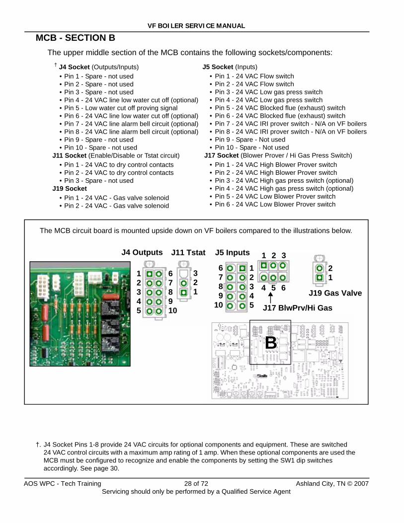
MCB - SECTION BThe upper middle section of the MCB contains the following sockets/components:
† J4 Socket (Outputs/Inputs)• Pin 1 - Spare - not used• Pin 2 - Spare - not used• Pin 3 - Spare - not used• Pin 4 - 24 VAC line low water cut off (optional)• Pin 5 - Low water cut off proving signal• Pin 6 - 24 VAC line low water cut off (optional)• Pin 7 - 24 VAC line alarm bell circuit (optional)• Pin 8 - 24 VAC line alarm bell circuit (optional)• Pin 9 - Spare - not used• Pin 10 - Spare - not used
J11 Socket (Enable/Disable or Tstat circuit)• Pin 1 - 24 VAC to dry control contacts• Pin 2 - 24 VAC to dry control contacts• Pin 3 - Spare - not used
J19 Socket • Pin 1 - 24 VAC - Gas valve solenoid• Pin 2 - 24 VAC - Gas valve solenoid
†. J4 Socket Pins 1-8 provide 24 VAC circuits for optional components and equipment. These are switched 24 VAC control circuits with a maximum amp rating of 1 amp. When these optional components are used the MCB must be configured to recognize and enable the components by setting the SW1 dip switches accordingly. See page 30.
B
211
2345
678910
12345
321
6789
10
1 2 3
4 5 6
J4 Outputs J11 Tstat J5 Inputs
J17 BlwPrv/Hi Gas
J19 Gas Valve
The MCB circuit board is mounted upside down on VF boilers compared to the illustrations below.
J5 Socket (Inputs)• Pin 1 - 24 VAC Flow switch• Pin 2 - 24 VAC Flow switch• Pin 3 - 24 VAC Low gas press switch• Pin 4 - 24 VAC Low gas press switch• Pin 5 - 24 VAC Blocked flue (exhaust) switch• Pin 6 - 24 VAC Blocked flue (exhaust) switch• Pin 7 - 24 VAC IRI prover switch - N/A on VF boilers• Pin 8 - 24 VAC IRI prover switch - N/A on VF boilers• Pin 9 - Spare - Not used• Pin 10 - Spare - Not used
J17 Socket (Blower Prover / Hi Gas Press Switch)• Pin 1 - 24 VAC High Blower Prover switch• Pin 2 - 24 VAC High Blower Prover switch• Pin 3 - 24 VAC High gas press switch (optional)• Pin 4 - 24 VAC High gas press switch (optional)• Pin 5 - 24 VAC Low Blower Prover switch • Pin 6 - 24 VAC Low Blower Prover switch
AOS WPC - Tech Training 28 of 72 Ashland City, TN © 2007Servicing should only be performed by a Qualified Service Agent
VF BOILER SERVICE MANUAL
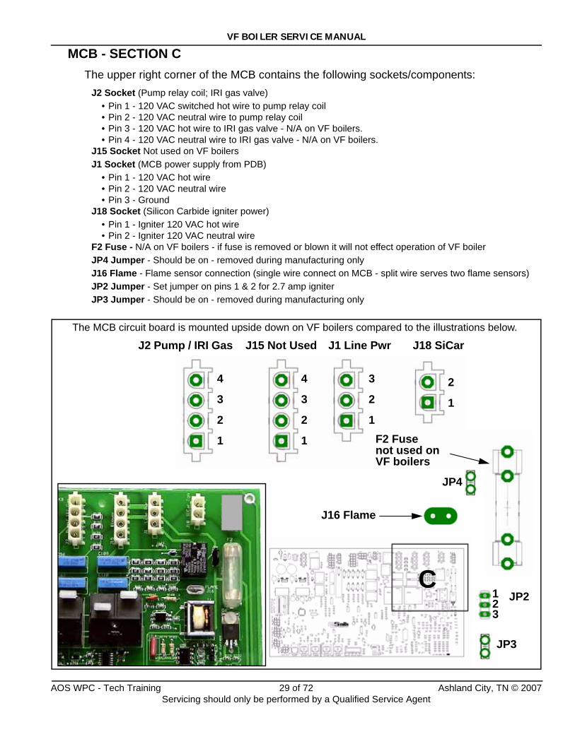
MCB - SECTION CThe upper right corner of the MCB contains the following sockets/components:
J2 Socket (Pump relay coil; IRI gas valve)• Pin 1 - 120 VAC switched hot wire to pump relay coil• Pin 2 - 120 VAC neutral wire to pump relay coil• Pin 3 - 120 VAC hot wire to IRI gas valve - N/A on VF boilers.• Pin 4 - 120 VAC neutral wire to IRI gas valve - N/A on VF boilers.
J15 Socket Not used on VF boilersJ1 Socket (MCB power supply from PDB)
• Pin 1 - 120 VAC hot wire• Pin 2 - 120 VAC neutral wire• Pin 3 - Ground
J18 Socket (Silicon Carbide igniter power)• Pin 1 - Igniter 120 VAC hot wire• Pin 2 - Igniter 120 VAC neutral wire
F2 Fuse - N/A on VF boilers - if fuse is removed or blown it will not effect operation of VF boilerJP4 Jumper - Should be on - removed during manufacturing onlyJ16 Flame - Flame sensor connection (single wire connect on MCB - split wire serves two flame sensors)JP2 Jumper - Set jumper on pins 1 & 2 for 2.7 amp igniterJP3 Jumper - Should be on - removed during manufacturing only
C
J2 Pump / IRI Gas J1 Line Pwr J18 SiCarJ15 Not Used
4
3
2
1
4
3
2
1
3
2
1
2
1
321
F2 Fusenot used on VF boilers
J16 Flame
JP2
JP3
JP4
The MCB circuit board is mounted upside down on VF boilers compared to the illustrations below.
123
AOS WPC - Tech Training 29 of 72 Ashland City, TN © 2007Servicing should only be performed by a Qualified Service Agent
VF BOILER SERVICE MANUAL
MCB - SECTION D
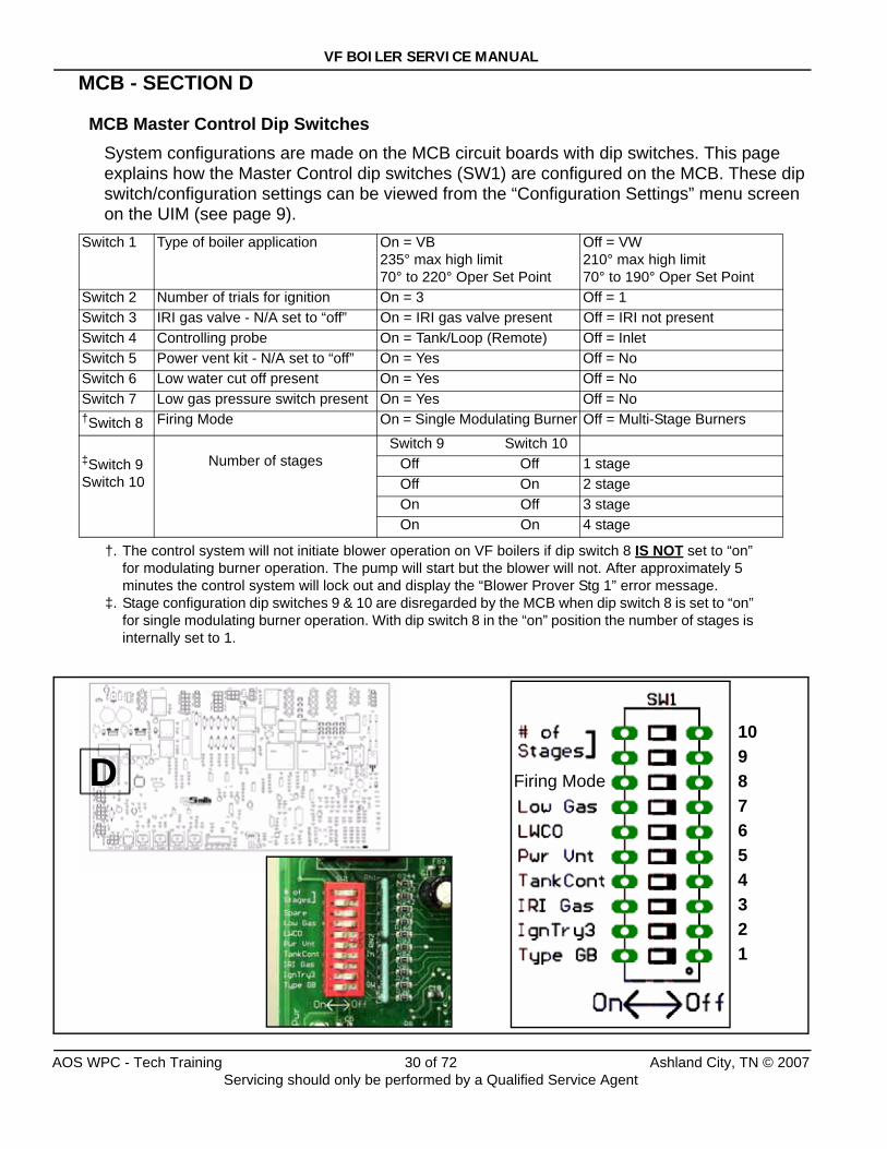
MCB Master Control Dip SwitchesSystem configurations are made on the MCB circuit boards with dip switches. This page explains how the Master Control dip switches (SW1) are configured on the MCB. These dip switch/configuration settings can be viewed from the “Configuration Settings” menu screen on the UIM (see page 9).
Switch 1 Type of boiler application On = VB 235° max high limit70° to 220° Oper Set Point
Off = VW 210° max high limit70° to 190° Oper Set Point
Switch 2 Number of trials for ignition On = 3 Off = 1Switch 3 IRI gas valve - N/A set to “off” On = IRI gas valve present Off = IRI not presentSwitch 4 Controlling probe On = Tank/Loop (Remote) Off = InletSwitch 5 Power vent kit - N/A set to “off” On = Yes Off = NoSwitch 6 Low water cut off present On = Yes Off = NoSwitch 7 Low gas pressure switch present On = Yes Off = No†Switch 8
†. The control system will not initiate blower operation on VF boilers if dip switch 8 IS NOT set to “on” for modulating burner operation. The pump will start but the blower will not. After approximately 5 minutes the control system will lock out and display the “Blower Prover Stg 1” error message.
Firing Mode On = Single Modulating Burner Off = Multi-Stage Burners
‡Switch 9Switch 10
‡. Stage configuration dip switches 9 & 10 are disregarded by the MCB when dip switch 8 is set to “on” for single modulating burner operation. With dip switch 8 in the “on” position the number of stages is internally set to 1.
Number of stagesSwitch 9 Switch 10
Off Off 1 stage Off On 2 stage On Off 3 stage On On 4 stage
D10987654321
Firing Mode
AOS WPC - Tech Training 30 of 72 Ashland City, TN © 2007Servicing should only be performed by a Qualified Service Agent
VF BOILER SERVICE MANUAL
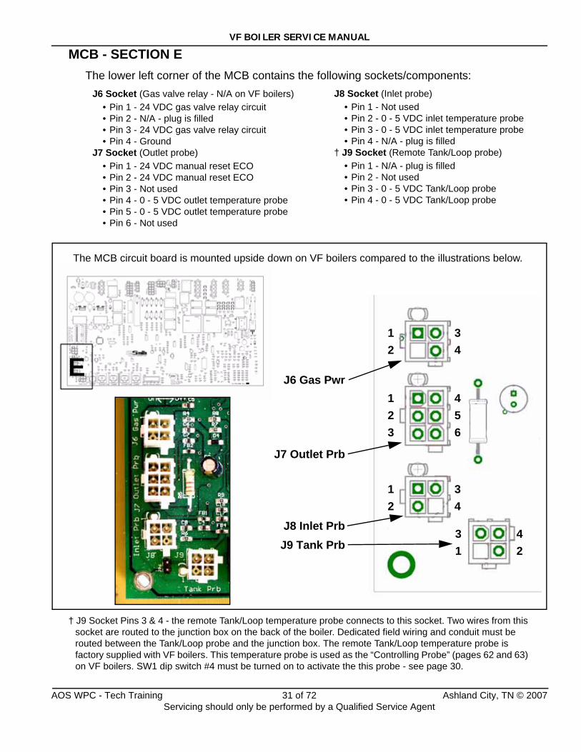
MCB - SECTION EThe lower left corner of the MCB contains the following sockets/components:
J6 Socket (Gas valve relay - N/A on VF boilers)• Pin 1 - 24 VDC gas valve relay circuit• Pin 2 - N/A - plug is filled• Pin 3 - 24 VDC gas valve relay circuit• Pin 4 - Ground
J7 Socket (Outlet probe)• Pin 1 - 24 VDC manual reset ECO • Pin 2 - 24 VDC manual reset ECO• Pin 3 - Not used• Pin 4 - 0 - 5 VDC outlet temperature probe• Pin 5 - 0 - 5 VDC outlet temperature probe• Pin 6 - Not used
† J9 Socket Pins 3 & 4 - the remote Tank/Loop temperature probe connects to this socket. Two wires from this socket are routed to the junction box on the back of the boiler. Dedicated field wiring and conduit must be routed between the Tank/Loop probe and the junction box. The remote Tank/Loop temperature probe is factory supplied with VF boilers. This temperature probe is used as the “Controlling Probe” (pages 62 and 63) on VF boilers. SW1 dip switch #4 must be turned on to activate the this probe - see page 30.
E123
456
12
42
31
34
12
34
J7 Outlet Prb
J9 Tank PrbJ8 Inlet Prb
J6 Gas Pwr
The MCB circuit board is mounted upside down on VF boilers compared to the illustrations below.
J8 Socket (Inlet probe)• Pin 1 - Not used• Pin 2 - 0 - 5 VDC inlet temperature probe• Pin 3 - 0 - 5 VDC inlet temperature probe• Pin 4 - N/A - plug is filled
† J9 Socket (Remote Tank/Loop probe)• Pin 1 - N/A - plug is filled• Pin 2 - Not used• Pin 3 - 0 - 5 VDC Tank/Loop probe• Pin 4 - 0 - 5 VDC Tank/Loop probe
AOS WPC - Tech Training 31 of 72 Ashland City, TN © 2007Servicing should only be performed by a Qualified Service Agent
VF BOILER SERVICE MANUAL
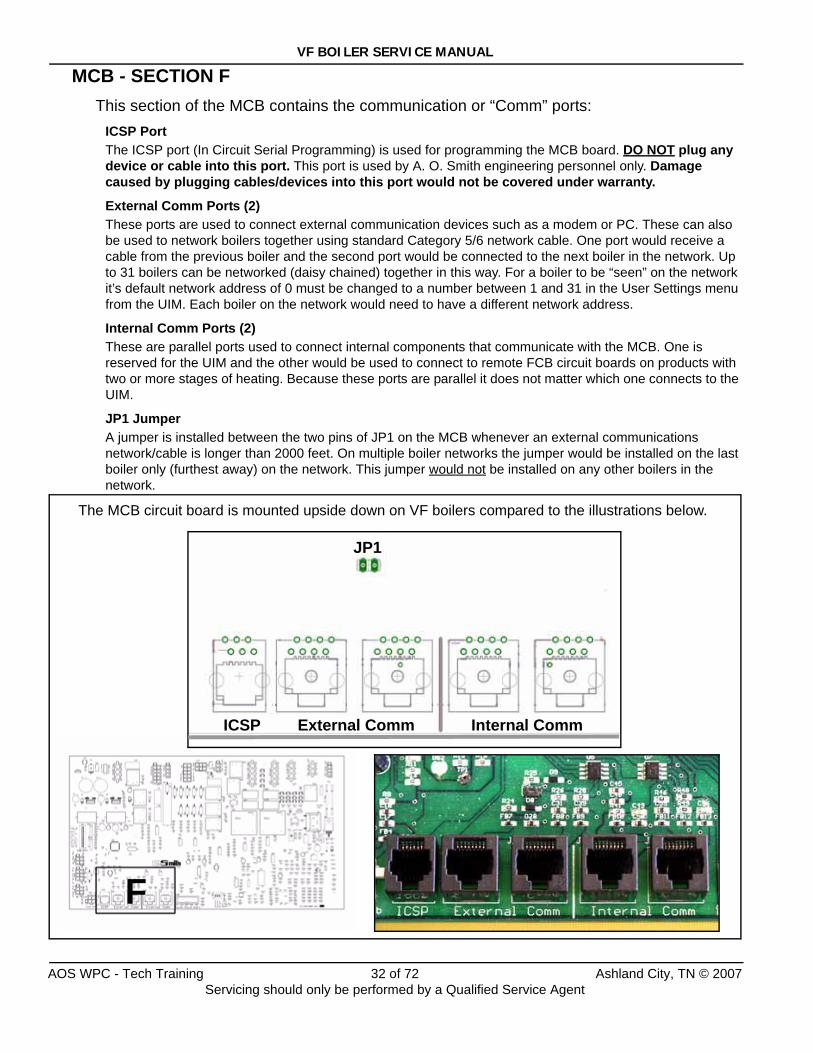
MCB - SECTION FThis section of the MCB contains the communication or “Comm” ports:
ICSP PortThe ICSP port (In Circuit Serial Programming) is used for programming the MCB board. DO NOT plug any device or cable into this port. This port is used by A. O. Smith engineering personnel only. Damage caused by plugging cables/devices into this port would not be covered under warranty.
External Comm Ports (2)These ports are used to connect external communication devices such as a modem or PC. These can also be used to network boilers together using standard Category 5/6 network cable. One port would receive a cable from the previous boiler and the second port would be connected to the next boiler in the network. Up to 31 boilers can be networked (daisy chained) together in this way. For a boiler to be “seen” on the network it’s default network address of 0 must be changed to a number between 1 and 31 in the User Settings menu from the UIM. Each boiler on the network would need to have a different network address.
Internal Comm Ports (2)These are parallel ports used to connect internal components that communicate with the MCB. One is reserved for the UIM and the other would be used to connect to remote FCB circuit boards on products with two or more stages of heating. Because these ports are parallel it does not matter which one connects to the UIM.
JP1 JumperA jumper is installed between the two pins of JP1 on the MCB whenever an external communications network/cable is longer than 2000 feet. On multiple boiler networks the jumper would be installed on the last boiler only (furthest away) on the network. This jumper would not be installed on any other boilers in the network.
F
ICSP
JP1
External Comm Internal Comm
The MCB circuit board is mounted upside down on VF boilers compared to the illustrations below.
AOS WPC - Tech Training 32 of 72 Ashland City, TN © 2007Servicing should only be performed by a Qualified Service Agent
VF BOILER SERVICE MANUAL
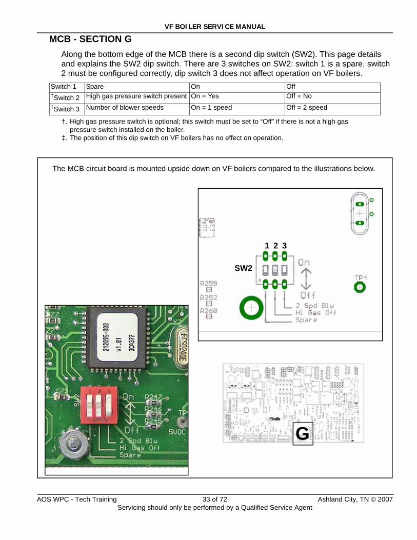
MCB - SECTION GAlong the bottom edge of the MCB there is a second dip switch (SW2). This page details and explains the SW2 dip switch. There are 3 switches on SW2: switch 1 is a spare, switch 2 must be configured correctly, dip switch 3 does not affect operation on VF boilers.
Switch 1 Spare On Off †Switch 2
†. High gas pressure switch is optional; this switch must be set to “Off” if there is not a high gas pressure switch installed on the boiler.
High gas pressure switch present On = Yes Off = No‡Switch 3
‡. The position of this dip switch on VF boilers has no effect on operation.
Number of blower speeds On = 1 speed Off = 2 speed
G
SW2
1 2 3
The MCB circuit board is mounted upside down on VF boilers compared to the illustrations below.
AOS WPC - Tech Training 33 of 72 Ashland City, TN © 2007Servicing should only be performed by a Qualified Service Agent
VF BOILER SERVICE MANUAL
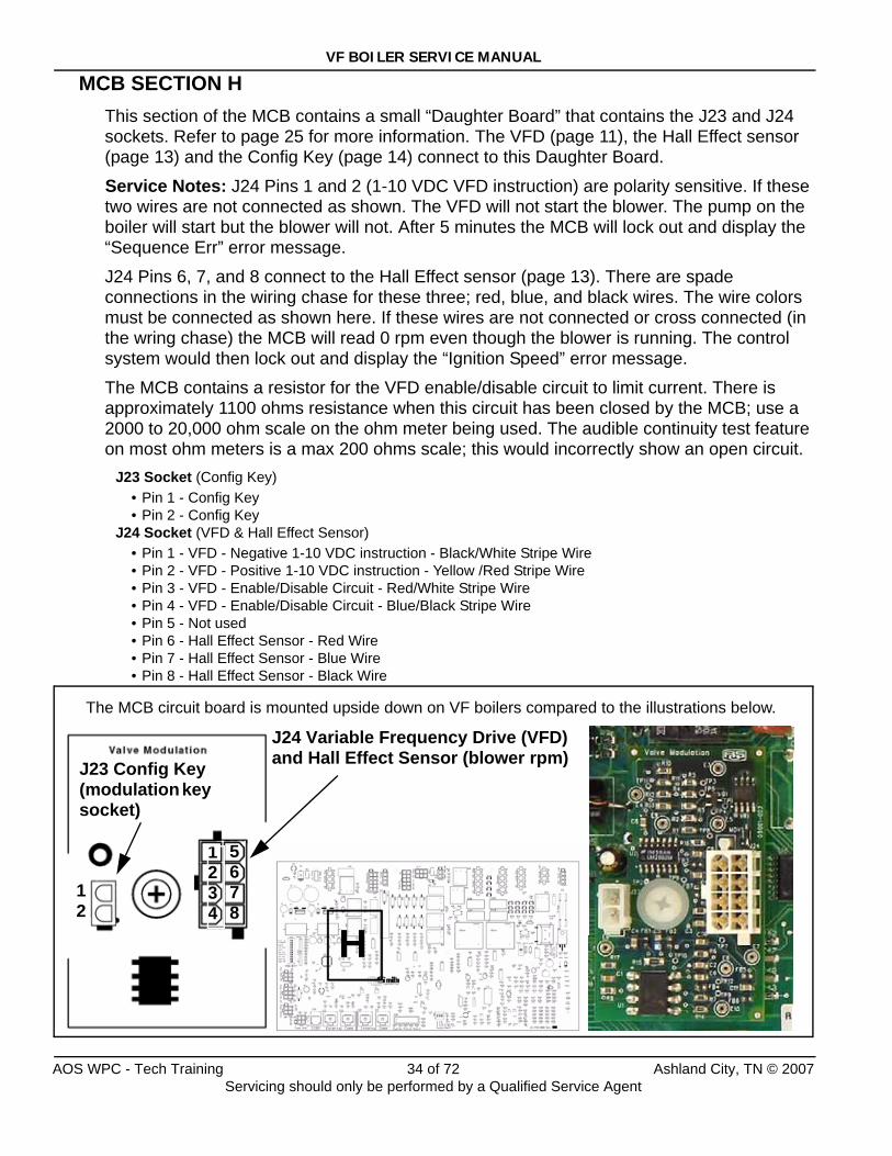
MCB SECTION HThis section of the MCB contains a small “Daughter Board” that contains the J23 and J24 sockets. Refer to page 25 for more information. The VFD (page 11), the Hall Effect sensor (page 13) and the Config Key (page 14) connect to this Daughter Board.
Service Notes: J24 Pins 1 and 2 (1-10 VDC VFD instruction) are polarity sensitive. If these two wires are not connected as shown. The VFD will not start the blower. The pump on the boiler will start but the blower will not. After 5 minutes the MCB will lock out and display the “Sequence Err” error message.
J24 Pins 6, 7, and 8 connect to the Hall Effect sensor (page 13). There are spade connections in the wiring chase for these three; red, blue, and black wires. The wire colors must be connected as shown here. If these wires are not connected or cross connected (in the wring chase) the MCB will read 0 rpm even though the blower is running. The control system would then lock out and display the “Ignition Speed” error message.
The MCB contains a resistor for the VFD enable/disable circuit to limit current. There is approximately 1100 ohms resistance when this circuit has been closed by the MCB; use a 2000 to 20,000 ohm scale on the ohm meter being used. The audible continuity test feature on most ohm meters is a max 200 ohms scale; this would incorrectly show an open circuit.
J23 Socket (Config Key)• Pin 1 - Config Key• Pin 2 - Config Key
J24 Socket (VFD & Hall Effect Sensor)• Pin 1 - VFD - Negative 1-10 VDC instruction - Black/White Stripe Wire• Pin 2 - VFD - Positive 1-10 VDC instruction - Yellow /Red Stripe Wire• Pin 3 - VFD - Enable/Disable Circuit - Red/White Stripe Wire• Pin 4 - VFD - Enable/Disable Circuit - Blue/Black Stripe Wire• Pin 5 - Not used• Pin 6 - Hall Effect Sensor - Red Wire• Pin 7 - Hall Effect Sensor - Blue Wire• Pin 8 - Hall Effect Sensor - Black Wire
H
5678
12
J23 Config Key(modulation key socket)
J24 Variable Frequency Drive (VFD) and Hall Effect Sensor (blower rpm)
1234
The MCB circuit board is mounted upside down on VF boilers compared to the illustrations below.
AOS WPC - Tech Training 34 of 72 Ashland City, TN © 2007Servicing should only be performed by a Qualified Service Agent
VF BOILER SERVICE MANUAL
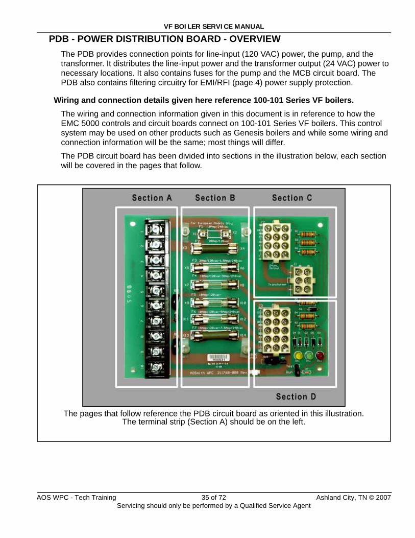
PDB - POWER DISTRIBUTION BOARD - OVERVIEWThe PDB provides connection points for line-input (120 VAC) power, the pump, and the transformer. It distributes the line-input power and the transformer output (24 VAC) power to necessary locations. It also contains fuses for the pump and the MCB circuit board. The PDB also contains filtering circuitry for EMI/RFI (page 4) power supply protection.
Wiring and connection details given here reference 100-101 Series VF boilers.The wiring and connection information given in this document is in reference to how the EMC 5000 controls and circuit boards connect on 100-101 Series VF boilers. This control system may be used on other products such as Genesis boilers and while some wiring and connection information will be the same; most things will differ.
The PDB circuit board has been divided into sections in the illustration below, each section will be covered in the pages that follow.
The pages that follow reference the PDB circuit board as oriented in this illustration.The terminal strip (Section A) should be on the left.
AOS WPC - Tech Training 35 of 72 Ashland City, TN © 2007Servicing should only be performed by a Qualified Service Agent
VF BOILER SERVICE MANUAL
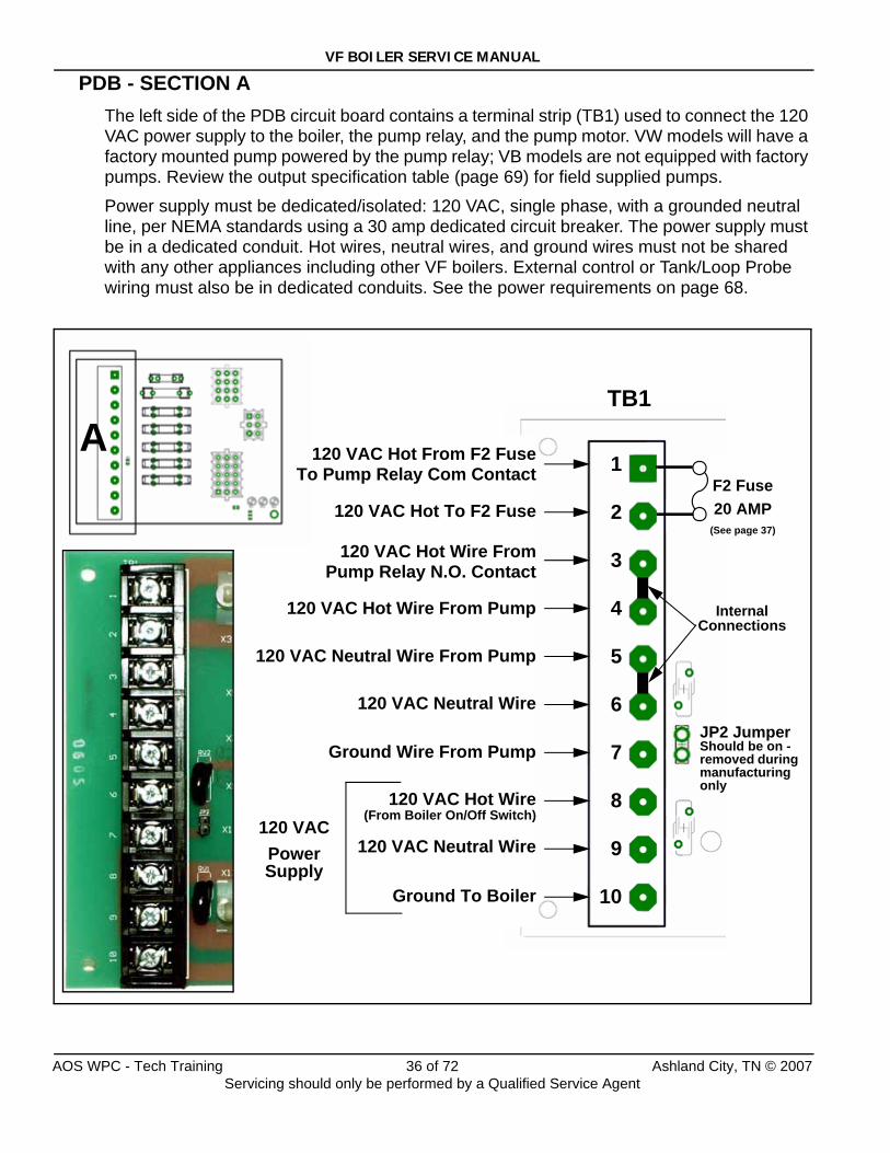
PDB - SECTION AThe left side of the PDB circuit board contains a terminal strip (TB1) used to connect the 120 VAC power supply to the boiler, the pump relay, and the pump motor. VW models will have a factory mounted pump powered by the pump relay; VB models are not equipped with factory pumps. Review the output specification table (page 69) for field supplied pumps.
Power supply must be dedicated/isolated: 120 VAC, single phase, with a grounded neutral line, per NEMA standards using a 30 amp dedicated circuit breaker. The power supply must be in a dedicated conduit. Hot wires, neutral wires, and ground wires must not be shared with any other appliances including other VF boilers. External control or Tank/Loop Probe wiring must also be in dedicated conduits. See the power requirements on page 68.
1
2
3
4
5
6
7
8
9
10
A
Ground To Boiler
JP2 Jumper Should be on - removed during manufacturing only
120 VAC Neutral Wire
120 VAC Hot Wire(From Boiler On/Off Switch)
120 VACPower Supply
Ground Wire From Pump
120 VAC Neutral Wire From Pump
120 VAC Hot Wire From Pump
120 VAC Neutral Wire
Internal Connections
120 VAC Hot To F2 Fuse
120 VAC Hot From F2 FuseTo Pump Relay Com Contact F2 Fuse
20 AMP(See page 37)
120 VAC Hot Wire FromPump Relay N.O. Contact
TB1
AOS WPC - Tech Training 36 of 72 Ashland City, TN © 2007Servicing should only be performed by a Qualified Service Agent
VF BOILER SERVICE MANUAL
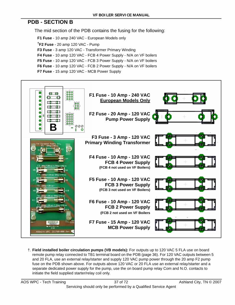
PDB - SECTION BThe mid section of the PDB contains the fusing for the following:
F1 Fuse - 10 amp 240 VAC - European Models only†F2 Fuse - 20 amp 120 VAC - PumpF3 Fuse - 3 amp 120 VAC - Transformer Primary WindingF4 Fuse - 10 amp 120 VAC - FCB 4 Power Supply - N/A on VF boilersF5 Fuse - 10 amp 120 VAC - FCB 3 Power Supply - N/A on VF boilersF6 Fuse - 10 amp 120 VAC - FCB 2 Power Supply - N/A on VF boilersF7 Fuse - 15 amp 120 VAC - MCB Power Supply
†. Field installed boiler circulation pumps (VB models): For outputs up to 120 VAC 5 FLA use on board remote pump relay connected to TB1 terminal board on the PDB (page 36). For 120 VAC outputs between 5 and 20 FLA, use an external relay/starter and supply 120 VAC pump power through the 20 amp F2 pump fuse on the PDB shown above. For outputs above 120 VAC or 20 FLA use an external relay/starter and a separate dedicated power supply for the pump, use the on board pump relay Com and N.O. contacts to initiate the field supplied starter/relay coil only.
BF2 Fuse - 20 Amp - 120 VAC
Pump Power Supply
F3 Fuse - 3 Amp - 120 VACPrimary Winding Transformer
F4 Fuse - 10 Amp - 120 VACFCB 4 Power Supply
(FCB 4 not used on VF Boilers)
F5 Fuse - 10 Amp - 120 VACFCB 3 Power Supply
(FCB 3 not used on VF Boilers)
F6 Fuse - 10 Amp - 120 VACFCB 2 Power Supply
(FCB 2 not used on VF Boilers
F7 Fuse - 15 Amp - 120 VACMCB Power Supply
F1 Fuse - 10 Amp - 240 VACEuropean Models Only
AOS WPC - Tech Training 37 of 72 Ashland City, TN © 2007Servicing should only be performed by a Qualified Service Agent
VF BOILER SERVICE MANUAL
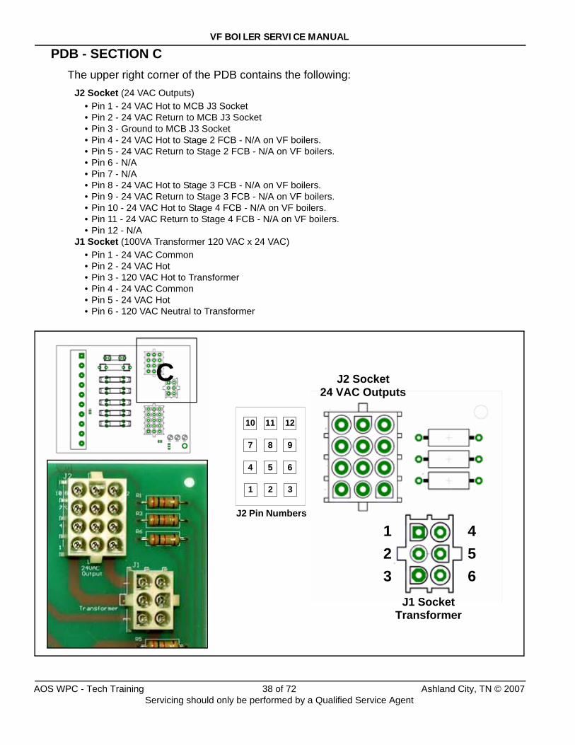
PDB - SECTION CThe upper right corner of the PDB contains the following:
J2 Socket (24 VAC Outputs)• Pin 1 - 24 VAC Hot to MCB J3 Socket• Pin 2 - 24 VAC Return to MCB J3 Socket• Pin 3 - Ground to MCB J3 Socket• Pin 4 - 24 VAC Hot to Stage 2 FCB - N/A on VF boilers.• Pin 5 - 24 VAC Return to Stage 2 FCB - N/A on VF boilers.• Pin 6 - N/A• Pin 7 - N/A• Pin 8 - 24 VAC Hot to Stage 3 FCB - N/A on VF boilers.• Pin 9 - 24 VAC Return to Stage 3 FCB - N/A on VF boilers.• Pin 10 - 24 VAC Hot to Stage 4 FCB - N/A on VF boilers.• Pin 11 - 24 VAC Return to Stage 4 FCB - N/A on VF boilers.• Pin 12 - N/A
J1 Socket (100VA Transformer 120 VAC x 24 VAC)• Pin 1 - 24 VAC Common• Pin 2 - 24 VAC Hot• Pin 3 - 120 VAC Hot to Transformer• Pin 4 - 24 VAC Common• Pin 5 - 24 VAC Hot• Pin 6 - 120 VAC Neutral to Transformer
C
321
654
987
121110
J2 Pin Numbers
J2 Socket24 VAC Outputs
J1 SocketTransformer
123
456
AOS WPC - Tech Training 38 of 72 Ashland City, TN © 2007Servicing should only be performed by a Qualified Service Agent
VF BOILER SERVICE MANUAL
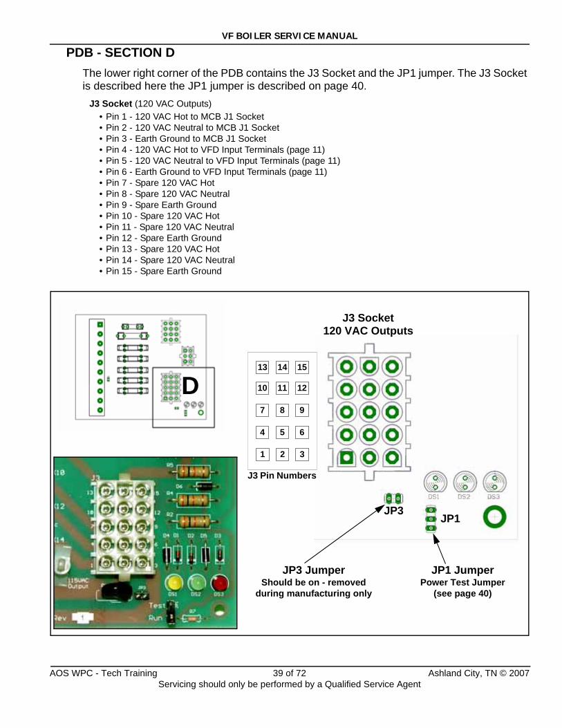
PDB - SECTION DThe lower right corner of the PDB contains the J3 Socket and the JP1 jumper. The J3 Socket is described here the JP1 jumper is described on page 40.
J3 Socket (120 VAC Outputs)• Pin 1 - 120 VAC Hot to MCB J1 Socket• Pin 2 - 120 VAC Neutral to MCB J1 Socket• Pin 3 - Earth Ground to MCB J1 Socket• Pin 4 - 120 VAC Hot to VFD Input Terminals (page 11)• Pin 5 - 120 VAC Neutral to VFD Input Terminals (page 11)• Pin 6 - Earth Ground to VFD Input Terminals (page 11)• Pin 7 - Spare 120 VAC Hot• Pin 8 - Spare 120 VAC Neutral• Pin 9 - Spare Earth Ground• Pin 10 - Spare 120 VAC Hot• Pin 11 - Spare 120 VAC Neutral• Pin 12 - Spare Earth Ground• Pin 13 - Spare 120 VAC Hot• Pin 14 - Spare 120 VAC Neutral• Pin 15 - Spare Earth Ground
JP1 JumperPower Test Jumper
(see page 40)
D
321
654
987
121110
151413
J3 Pin Numbers
J3 Socket120 VAC Outputs
JP1
JP3 JumperShould be on - removed
during manufacturing only
JP3
AOS WPC - Tech Training 39 of 72 Ashland City, TN © 2007Servicing should only be performed by a Qualified Service Agent
VF BOILER SERVICE MANUAL
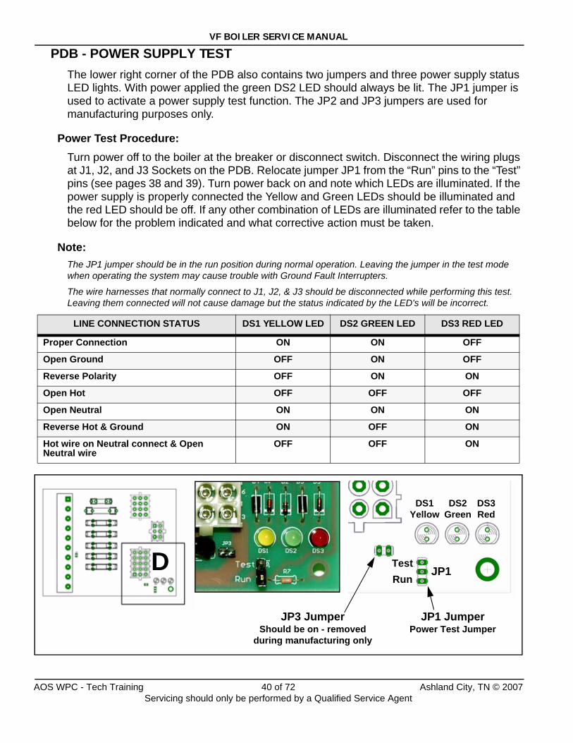
PDB - POWER SUPPLY TESTThe lower right corner of the PDB also contains two jumpers and three power supply status LED lights. With power applied the green DS2 LED should always be lit. The JP1 jumper is used to activate a power supply test function. The JP2 and JP3 jumpers are used for manufacturing purposes only.
Power Test Procedure:Turn power off to the boiler at the breaker or disconnect switch. Disconnect the wiring plugs at J1, J2, and J3 Sockets on the PDB. Relocate jumper JP1 from the “Run” pins to the “Test” pins (see pages 38 and 39). Turn power back on and note which LEDs are illuminated. If the power supply is properly connected the Yellow and Green LEDs should be illuminated and the red LED should be off. If any other combination of LEDs are illuminated refer to the table below for the problem indicated and what corrective action must be taken.
Note:The JP1 jumper should be in the run position during normal operation. Leaving the jumper in the test mode when operating the system may cause trouble with Ground Fault Interrupters.
The wire harnesses that normally connect to J1, J2, & J3 should be disconnected while performing this test. Leaving them connected will not cause damage but the status indicated by the LED's will be incorrect.
LINE CONNECTION STATUS DS1 YELLOW LED DS2 GREEN LED DS3 RED LED
Proper Connection ON ON OFF
Open Ground OFF ON OFF
Reverse Polarity OFF ON ON
Open Hot OFF OFF OFF
Open Neutral ON ON ON
Reverse Hot & Ground ON OFF ON
Hot wire on Neutral connect & Open Neutral wire
OFF OFF ON
D
DS1Yellow
DS2Green
DS3Red
JP1
JP3 JumperShould be on - removed
during manufacturing only
TestRun
JP1 JumperPower Test Jumper
AOS WPC - Tech Training 40 of 72 Ashland City, TN © 2007Servicing should only be performed by a Qualified Service Agent
VF BOILER SERVICE MANUAL
ERROR MESSAGES - TROUBLESHOOTINGThe EMC 5000 control system performs exhaustive self diagnostics and displays detected fault conditions on the UIM (page 6). There are approximately 80 different error messages. Troubleshooting procedures for the most common error messages are covered in this service manual. A more complete list of error messages is in the boiler’s Instruction Manual.
The troubleshooting procedures shown here relate to the EMC 5000 control system on VF boilers VW/VB 500 - 1000 Series 100/101 only.The first column in the tables that follow show the actual error message as displayed by the UIM along with an explanation. The second column details things to check or repair.
Use the System Status menu when troubleshooting:This menu is used to view the status of various components/switches, gas valve, flame sensors etc. An asterisk (*) is displayed next to a menu item when the status is true or on, the asterisk is not displayed when the status of a menu item is false or off. To access this menu press the Menu button on the UIM, navigate to the “System Status” menu and press Select. Using the information here along with the Sequence of Operation on page 15 is very helpful when troubleshooting. IE; if water flow is detected by the flow switch (flow switch contacts are closed) an asterisk (*) will appear in front of the Flow menu item; *Flow.
Things to check before servicing:• Using the Instruction Manual that came with the boiler as reference, verify the water
piping, gas line, venting, electrical, and controls are all properly installed.• Ensure SW1 dip switch #8 is turned on for Single Modulating Burner operation (page 30).• Ensure the Config Key is the correct key for the Btu/hr input and fuel type (page 14).• Ensure 120 VAC is supplied to the boiler and that the polarity is correct per the electrical
requirements on page 68. 120 VAC hot wire to black, neutral to white in the junction box.• Ensure minimum supply gas pressure is supplied to the boiler.
Resetting the EMC 5000 control:Reset the EMC 5000 control by touching the Select button while the “Current Error” menu screen (page 8) is displayed by the UIM.
IMORTANT SERVICE REMINDER:When performing any troubleshooting step outlined in this service manual always consider the wiring and connectors between components. Perform a close visual inspection of all wiring and connectors to and from a given component before replacement.
Ensure wires were stripped before being crimped in a wire connector, ensure wires are crimped tightly in their connectors, ensure connection pins in sockets and plugs are not damaged or worn, ensure plugs and sockets are mating properly and providing good contact.
Failure to perform this critical step or to perform this step thoroughly often results in needless down time, unnecessary parts replacement, and customer dissatisfaction.
AOS WPC - Tech Training 41 of 72 Ashland City, TN © 2007Servicing should only be performed by a Qualified Service Agent

VF BOILER SERVICE MANUAL
ERROR MESSAGES
DISPLAYED MESSAGECONDITION/INDICATES CHECK/REPAIR
UIM Display Is Blank
Boiler is turned off120 VAC power supply problems24 VAC power supply problemsBlown FusesDefective transformerWiring or plug/socket connection problemsUIM communication cable problems
Important Service Reminder:
When performing any troubleshooting steps outlined in this service manual always consider the wiring and connectors between components. Perform a close visual inspection of all wiring and connectors to a given component before replacement.
Ensure wires were stripped before being crimped in a wire connector, ensure wires are crimped tightly in their connectors, ensure connection pins in sockets and plugs are not damaged or worn, ensure plugs and sockets are mating properly and providing good contact.
Failure to perform this critical step or failing to perform this step thoroughly often results in needless down time, unnecessary parts replacement, and customer dissatisfaction.
• Ensure the on/off switch is on and working - replace switch if defective.
• Ensure 7.5 amp fuse on MCB is not blown/miss-ing - replace fuse (see page 27).
• Check comm cable connections at UIM and the MCB’s Internal Comm Ports. Secure power and install a new comm cable. (standard Cat 5 net-work cable). Plug UIM comm cable into other “internal” comm port on the MCB (page 32).
• Closely inspect communication ports on MCB and UIM for damage or wear (page 32).
• Ensure 120 VAC power is properly connected in the junction box on the back of the boiler.
• Ensure 120 VAC is supplied to TB1 terminals 8 and 9 on the PDB. Hot wire to terminal 8, neu-tral wire to terminal 9 (page 36).
• Ensure F7 fuse on PDB is not blown/missing (page 37) - replace fuse.
• Check F3 transformer fuse on PDB (page 37) if fuse is blown check wiring for shorts - then replace fuse.
• Check 120 VAC to transformer at the primary winding terminals on the transformer. If not present check wiring from PDB J1 socket.
• Check for 120 VAC between pins 3 & 6 of the J1 socket on the PDB (page 38). Perform this test with the wiring harness plugged into the J1 Socket. Ensure the J1 socket and plug are mak-ing good contact.
• Check for 24 VAC output at the transformer sec-ondary winding terminals - if 24 VAC is not present AND the two checks above were per-formed and the results were successful - replace the transformer. Check all wiring for shorts before powering up the new transformer.
• Check for 24VAC between pins 1 & 2 and between pins 4 & 5 of the J1 Socket on the PDB (page 38). Perform this test with the wiring har-ness plugged into the J1 Socket.
• Ensure the pins in the J1 socket on the PDB and the pins in the J1 plug and wiring harness are in good condition and making good contact. Repair or replace any parts that are worn, dam-aged, or failing to make a good connection.
AOS WPC - Tech Training 42 of 72 Ashland City, TN © 2007Servicing should only be performed by a Qualified Service Agent
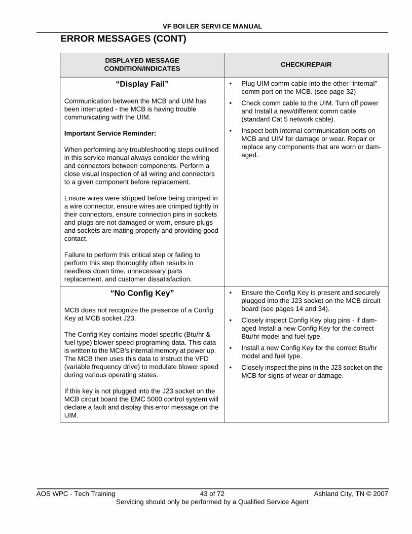
VF BOILER SERVICE MANUAL
ERROR MESSAGES (CONT)
DISPLAYED MESSAGECONDITION/INDICATES CHECK/REPAIR
“Display Fail”
Communication between the MCB and UIM has been interrupted - the MCB is having trouble communicating with the UIM.
Important Service Reminder:
When performing any troubleshooting steps outlined in this service manual always consider the wiring and connectors between components. Perform a close visual inspection of all wiring and connectors to a given component before replacement.
Ensure wires were stripped before being crimped in a wire connector, ensure wires are crimped tightly in their connectors, ensure connection pins in sockets and plugs are not damaged or worn, ensure plugs and sockets are mating properly and providing good contact.
Failure to perform this critical step or failing to perform this step thoroughly often results in needless down time, unnecessary parts replacement, and customer dissatisfaction.
• Plug UIM comm cable into the other “internal” comm port on the MCB. (see page 32)
• Check comm cable to the UIM. Turn off power and Install a new/different comm cable(standard Cat 5 network cable).
• Inspect both internal communication ports on MCB and UIM for damage or wear. Repair or replace any components that are worn or dam-aged.
“No Config Key”
MCB does not recognize the presence of a Config Key at MCB socket J23.
The Config Key contains model specific (Btu/hr & fuel type) blower speed programing data. This data is written to the MCB’s internal memory at power up. The MCB then uses this data to instruct the VFD (variable frequency drive) to modulate blower speed during various operating states.
If this key is not plugged into the J23 socket on the MCB circuit board the EMC 5000 control system will declare a fault and display this error message on the UIM.
• Ensure the Config Key is present and securely plugged into the J23 socket on the MCB circuit board (see pages 14 and 34).
• Closely inspect Config Key plug pins - if dam-aged Install a new Config Key for the correct Btu/hr model and fuel type.
• Install a new Config Key for the correct Btu/hr model and fuel type.
• Closely inspect the pins in the J23 socket on the MCB for signs of wear or damage.
AOS WPC - Tech Training 43 of 72 Ashland City, TN © 2007Servicing should only be performed by a Qualified Service Agent
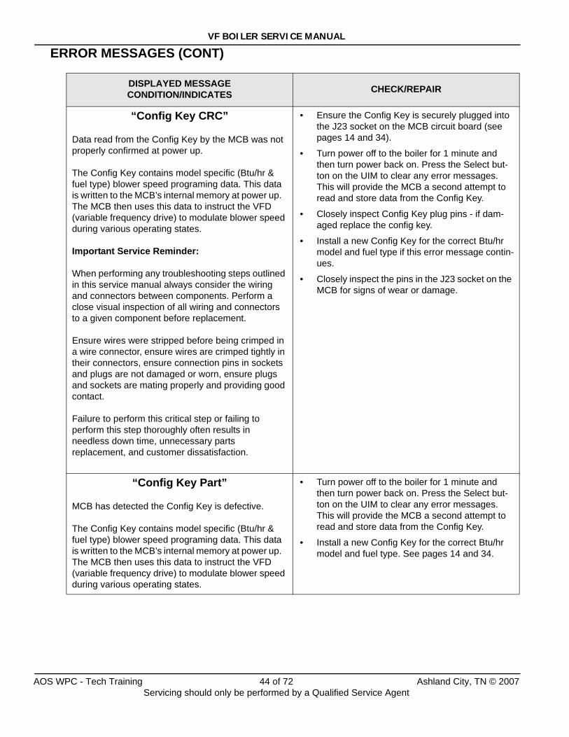
VF BOILER SERVICE MANUAL
ERROR MESSAGES (CONT)
DISPLAYED MESSAGECONDITION/INDICATES CHECK/REPAIR
“Config Key CRC”
Data read from the Config Key by the MCB was not properly confirmed at power up.
The Config Key contains model specific (Btu/hr & fuel type) blower speed programing data. This data is written to the MCB’s internal memory at power up. The MCB then uses this data to instruct the VFD (variable frequency drive) to modulate blower speed during various operating states.
Important Service Reminder:
When performing any troubleshooting steps outlined in this service manual always consider the wiring and connectors between components. Perform a close visual inspection of all wiring and connectors to a given component before replacement.
Ensure wires were stripped before being crimped in a wire connector, ensure wires are crimped tightly in their connectors, ensure connection pins in sockets and plugs are not damaged or worn, ensure plugs and sockets are mating properly and providing good contact.
Failure to perform this critical step or failing to perform this step thoroughly often results in needless down time, unnecessary parts replacement, and customer dissatisfaction.
• Ensure the Config Key is securely plugged into the J23 socket on the MCB circuit board (see pages 14 and 34).
• Turn power off to the boiler for 1 minute and then turn power back on. Press the Select but-ton on the UIM to clear any error messages. This will provide the MCB a second attempt to read and store data from the Config Key.
• Closely inspect Config Key plug pins - if dam-aged replace the config key.
• Install a new Config Key for the correct Btu/hr model and fuel type if this error message contin-ues.
• Closely inspect the pins in the J23 socket on the MCB for signs of wear or damage.
“Config Key Part”
MCB has detected the Config Key is defective.
The Config Key contains model specific (Btu/hr & fuel type) blower speed programing data. This data is written to the MCB’s internal memory at power up. The MCB then uses this data to instruct the VFD (variable frequency drive) to modulate blower speed during various operating states.
• Turn power off to the boiler for 1 minute and then turn power back on. Press the Select but-ton on the UIM to clear any error messages. This will provide the MCB a second attempt to read and store data from the Config Key.
• Install a new Config Key for the correct Btu/hr model and fuel type. See pages 14 and 34.
AOS WPC - Tech Training 44 of 72 Ashland City, TN © 2007Servicing should only be performed by a Qualified Service Agent
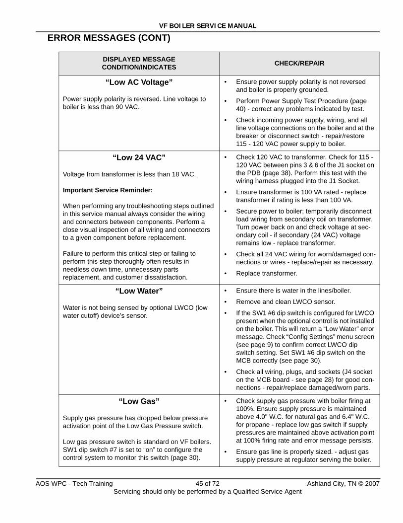
VF BOILER SERVICE MANUAL
ERROR MESSAGES (CONT)
DISPLAYED MESSAGECONDITION/INDICATES CHECK/REPAIR
“Low AC Voltage”
Power supply polarity is reversed. Line voltage to boiler is less than 90 VAC.
• Ensure power supply polarity is not reversed and boiler is properly grounded.
• Perform Power Supply Test Procedure (page 40) - correct any problems indicated by test.
• Check incoming power supply, wiring, and all line voltage connections on the boiler and at the breaker or disconnect switch - repair/restore 115 - 120 VAC power supply to boiler.
“Low 24 VAC”
Voltage from transformer is less than 18 VAC.
Important Service Reminder:
When performing any troubleshooting steps outlined in this service manual always consider the wiring and connectors between components. Perform a close visual inspection of all wiring and connectors to a given component before replacement.
Failure to perform this critical step or failing to perform this step thoroughly often results in needless down time, unnecessary parts replacement, and customer dissatisfaction.
• Check 120 VAC to transformer. Check for 115 - 120 VAC between pins 3 & 6 of the J1 socket on the PDB (page 38). Perform this test with the wiring harness plugged into the J1 Socket.
• Ensure transformer is 100 VA rated - replace transformer if rating is less than 100 VA.
• Secure power to boiler; temporarily disconnect load wiring from secondary coil on transformer. Turn power back on and check voltage at sec-ondary coil - if secondary (24 VAC) voltage remains low - replace transformer.
• Check all 24 VAC wiring for worn/damaged con-nections or wires - replace/repair as necessary.
• Replace transformer.
“Low Water”
Water is not being sensed by optional LWCO (low water cutoff) device’s sensor.
• Ensure there is water in the lines/boiler.
• Remove and clean LWCO sensor.
• If the SW1 #6 dip switch is configured for LWCO present when the optional control is not installed on the boiler. This will return a “Low Water” error message. Check “Config Settings” menu screen (see page 9) to confirm correct LWCO dip switch setting. Set SW1 #6 dip switch on the MCB correctly (see page 30).
• Check all wiring, plugs, and sockets (J4 socket on the MCB board - see page 28) for good con-nections - repair/replace damaged/worn parts.
“Low Gas”
Supply gas pressure has dropped below pressure activation point of the Low Gas Pressure switch.
Low gas pressure switch is standard on VF boilers. SW1 dip switch #7 is set to “on” to configure the control system to monitor this switch (page 30).
• Check supply gas pressure with boiler firing at 100%. Ensure supply pressure is maintained above 4.0" W.C. for natural gas and 6.4" W.C. for propane - replace low gas switch if supply pressures are maintained above activation point at 100% firing rate and error message persists.
• Ensure gas line is properly sized. - adjust gas supply pressure at regulator serving the boiler.
AOS WPC - Tech Training 45 of 72 Ashland City, TN © 2007Servicing should only be performed by a Qualified Service Agent
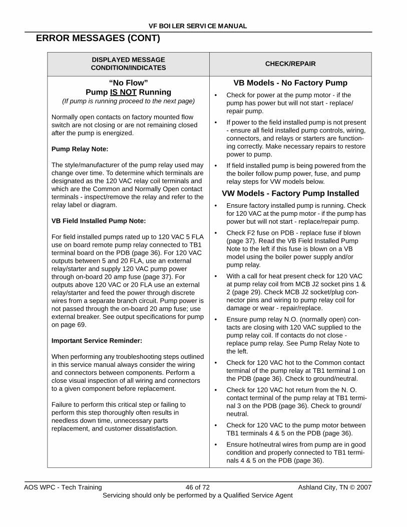
VF BOILER SERVICE MANUAL
ERROR MESSAGES (CONT)
DISPLAYED MESSAGECONDITION/INDICATES CHECK/REPAIR
“No Flow”Pump IS NOT Running
(If pump is running proceed to the next page)
Normally open contacts on factory mounted flow switch are not closing or are not remaining closed after the pump is energized.
Pump Relay Note:
The style/manufacturer of the pump relay used may change over time. To determine which terminals are designated as the 120 VAC relay coil terminals and which are the Common and Normally Open contact terminals - inspect/remove the relay and refer to the relay label or diagram.
VB Field Installed Pump Note:
For field installed pumps rated up to 120 VAC 5 FLA use on board remote pump relay connected to TB1 terminal board on the PDB (page 36). For 120 VAC outputs between 5 and 20 FLA, use an external relay/starter and supply 120 VAC pump power through on-board 20 amp fuse (page 37). For outputs above 120 VAC or 20 FLA use an external relay/starter and feed the power through discrete wires from a separate branch circuit. Pump power is not passed through the on-board 20 amp fuse; use external breaker. See output specifications for pump on page 69.
Important Service Reminder:
When performing any troubleshooting steps outlined in this service manual always consider the wiring and connectors between components. Perform a close visual inspection of all wiring and connectors to a given component before replacement.
Failure to perform this critical step or failing to perform this step thoroughly often results in needless down time, unnecessary parts replacement, and customer dissatisfaction.
VB Models - No Factory Pump• Check for power at the pump motor - if the
pump has power but will not start - replace/repair pump.
• If power to the field installed pump is not present - ensure all field installed pump controls, wiring, connectors, and relays or starters are function-ing correctly. Make necessary repairs to restore power to pump.
• If field installed pump is being powered from the the boiler follow pump power, fuse, and pump relay steps for VW models below.
VW Models - Factory Pump Installed• Ensure factory installed pump is running. Check
for 120 VAC at the pump motor - if the pump has power but will not start - replace/repair pump.
• Check F2 fuse on PDB - replace fuse if blown (page 37). Read the VB Field Installed Pump Note to the left if this fuse is blown on a VB model using the boiler power supply and/or pump relay.
• With a call for heat present check for 120 VAC at pump relay coil from MCB J2 socket pins 1 & 2 (page 29). Check MCB J2 socket/plug con-nector pins and wiring to pump relay coil for damage or wear - repair/replace.
• Ensure pump relay N.O. (normally open) con-tacts are closing with 120 VAC supplied to the pump relay coil. If contacts do not close - replace pump relay. See Pump Relay Note to the left.
• Check for 120 VAC hot to the Common contact terminal of the pump relay at TB1 terminal 1 on the PDB (page 36). Check to ground/neutral.
• Check for 120 VAC hot return from the N. O. contact terminal of the pump relay at TB1 termi-nal 3 on the PDB (page 36). Check to ground/neutral.
• Check for 120 VAC to the pump motor between TB1 terminals 4 & 5 on the PDB (page 36).
• Ensure hot/neutral wires from pump are in good condition and properly connected to TB1 termi-nals 4 & 5 on the PDB (page 36).
AOS WPC - Tech Training 46 of 72 Ashland City, TN © 2007Servicing should only be performed by a Qualified Service Agent
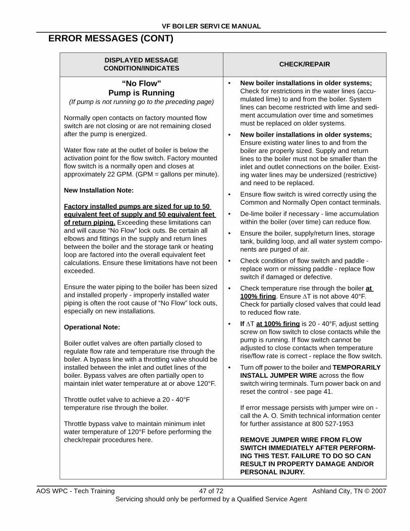
VF BOILER SERVICE MANUAL
ERROR MESSAGES (CONT)
DISPLAYED MESSAGECONDITION/INDICATES CHECK/REPAIR
“No Flow”Pump is Running
(If pump is not running go to the preceding page)
Normally open contacts on factory mounted flow switch are not closing or are not remaining closed after the pump is energized.
Water flow rate at the outlet of boiler is below the activation point for the flow switch. Factory mounted flow switch is a normally open and closes at approximately 22 GPM. (GPM = gallons per minute).
New Installation Note:
Factory installed pumps are sized for up to 50 equivalent feet of supply and 50 equivalent feet of return piping. Exceeding these limitations can and will cause “No Flow” lock outs. Be certain all elbows and fittings in the supply and return lines between the boiler and the storage tank or heating loop are factored into the overall equivalent feet calculations. Ensure these limitations have not been exceeded.
Ensure the water piping to the boiler has been sized and installed properly - improperly installed water piping is often the root cause of “No Flow” lock outs, especially on new installations.
Operational Note:
Boiler outlet valves are often partially closed to regulate flow rate and temperature rise through the boiler. A bypass line with a throttling valve should be installed between the inlet and outlet lines of the boiler. Bypass valves are often partially open to maintain inlet water temperature at or above 120°F.
Throttle outlet valve to achieve a 20 - 40°F temperature rise through the boiler.
Throttle bypass valve to maintain minimum inlet water temperature of 120°F before performing the check/repair procedures here.
• New boiler installations in older systems; Check for restrictions in the water lines (accu-mulated lime) to and from the boiler. System lines can become restricted with lime and sedi-ment accumulation over time and sometimes must be replaced on older systems.
• New boiler installations in older systems; Ensure existing water lines to and from the boiler are properly sized. Supply and return lines to the boiler must not be smaller than the inlet and outlet connections on the boiler. Exist-ing water lines may be undersized (restrictive) and need to be replaced.
• Ensure flow switch is wired correctly using the Common and Normally Open contact terminals.
• De-lime boiler if necessary - lime accumulation within the boiler (over time) can reduce flow.
• Ensure the boiler, supply/return lines, storage tank, building loop, and all water system compo-nents are purged of air.
• Check condition of flow switch and paddle - replace worn or missing paddle - replace flow switch if damaged or defective.
• Check temperature rise through the boiler at 100% firing. Ensure ΔT is not above 40°F. Check for partially closed valves that could lead to reduced flow rate.
• If ΔT at 100% firing is 20 - 40°F, adjust setting screw on flow switch to close contacts while the pump is running. If flow switch cannot be adjusted to close contacts when temperature rise/flow rate is correct - replace the flow switch.
• Turn off power to the boiler and TEMPORARILY INSTALL JUMPER WIRE across the flow switch wiring terminals. Turn power back on and reset the control - see page 41.
If error message persists with jumper wire on - call the A. O. Smith technical information center for further assistance at 800 527-1953
REMOVE JUMPER WIRE FROM FLOW SWITCH IMMEDIATELY AFTER PERFORM-ING THIS TEST. FAILURE TO DO SO CAN RESULT IN PROPERTY DAMAGE AND/OR PERSONAL INJURY.
AOS WPC - Tech Training 47 of 72 Ashland City, TN © 2007Servicing should only be performed by a Qualified Service Agent
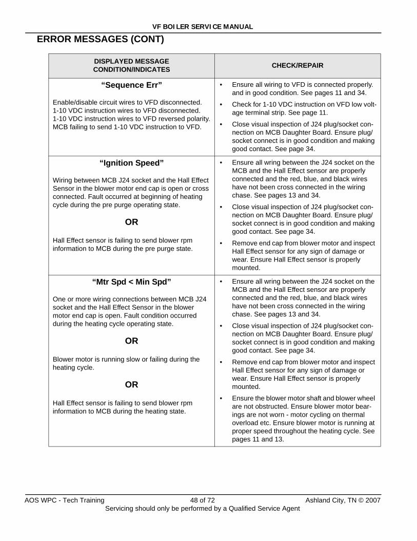
VF BOILER SERVICE MANUAL
ERROR MESSAGES (CONT)
DISPLAYED MESSAGECONDITION/INDICATES CHECK/REPAIR
“Sequence Err”
Enable/disable circuit wires to VFD disconnected.1-10 VDC instruction wires to VFD disconnected.1-10 VDC instruction wires to VFD reversed polarity.MCB failing to send 1-10 VDC instruction to VFD.
• Ensure all wiring to VFD is connected properly. and in good condition. See pages 11 and 34.
• Check for 1-10 VDC instruction on VFD low volt-age terminal strip. See page 11.
• Close visual inspection of J24 plug/socket con-nection on MCB Daughter Board. Ensure plug/socket connect is in good condition and making good contact. See page 34.
“Ignition Speed”
Wiring between MCB J24 socket and the Hall Effect Sensor in the blower motor end cap is open or cross connected. Fault occurred at beginning of heating cycle during the pre purge operating state.
OR
Hall Effect sensor is failing to send blower rpm information to MCB during the pre purge state.
• Ensure all wring between the J24 socket on the MCB and the Hall Effect sensor are properly connected and the red, blue, and black wires have not been cross connected in the wiring chase. See pages 13 and 34.
• Close visual inspection of J24 plug/socket con-nection on MCB Daughter Board. Ensure plug/socket connect is in good condition and making good contact. See page 34.
• Remove end cap from blower motor and inspect Hall Effect sensor for any sign of damage or wear. Ensure Hall Effect sensor is properly mounted.
“Mtr Spd < Min Spd”
One or more wiring connections between MCB J24 socket and the Hall Effect Sensor in the blower motor end cap is open. Fault condition occurred during the heating cycle operating state.
OR
Blower motor is running slow or failing during the heating cycle.
OR
Hall Effect sensor is failing to send blower rpm information to MCB during the heating state.
• Ensure all wring between the J24 socket on the MCB and the Hall Effect sensor are properly connected and the red, blue, and black wires have not been cross connected in the wiring chase. See pages 13 and 34.
• Close visual inspection of J24 plug/socket con-nection on MCB Daughter Board. Ensure plug/socket connect is in good condition and making good contact. See page 34.
• Remove end cap from blower motor and inspect Hall Effect sensor for any sign of damage or wear. Ensure Hall Effect sensor is properly mounted.
• Ensure the blower motor shaft and blower wheel are not obstructed. Ensure blower motor bear-ings are not worn - motor cycling on thermal overload etc. Ensure blower motor is running at proper speed throughout the heating cycle. See pages 11 and 13.
AOS WPC - Tech Training 48 of 72 Ashland City, TN © 2007Servicing should only be performed by a Qualified Service Agent
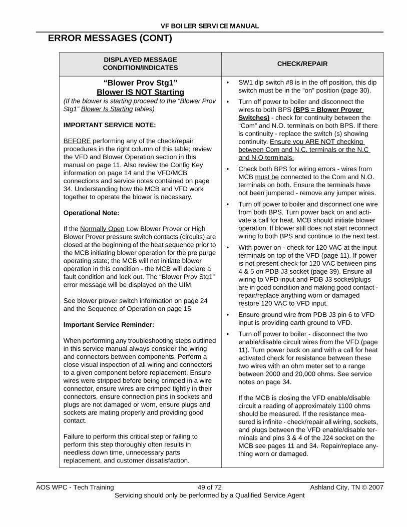
VF BOILER SERVICE MANUAL
ERROR MESSAGES (CONT)
DISPLAYED MESSAGECONDITION/INDICATES CHECK/REPAIR
“Blower Prov Stg1”Blower IS NOT Starting
(If the blower is starting proceed to the “Blower Prov Stg1” Blower Is Starting tables)
IMPORTANT SERVICE NOTE:
BEFORE performing any of the check/repair procedures in the right column of this table; review the VFD and Blower Operation section in this manual on page 11. Also review the Config Key information on page 14 and the VFD/MCB connections and service notes contained on page 34. Understanding how the MCB and VFD work together to operate the blower is necessary.
Operational Note:
If the Normally Open Low Blower Prover or High Blower Prover pressure switch contacts (circuits) are closed at the beginning of the heat sequence prior to the MCB initiating blower operation for the pre purge operating state; the MCB will not initiate blower operation in this condition - the MCB will declare a fault condition and lock out. The “Blower Prov Stg1” error message will be displayed on the UIM.
See blower prover switch information on page 24 and the Sequence of Operation on page 15
Important Service Reminder:
When performing any troubleshooting steps outlined in this service manual always consider the wiring and connectors between components. Perform a close visual inspection of all wiring and connectors to a given component before replacement. Ensure wires were stripped before being crimped in a wire connector, ensure wires are crimped tightly in their connectors, ensure connection pins in sockets and plugs are not damaged or worn, ensure plugs and sockets are mating properly and providing good contact.
Failure to perform this critical step or failing to perform this step thoroughly often results in needless down time, unnecessary parts replacement, and customer dissatisfaction.
• SW1 dip switch #8 is in the off position, this dip switch must be in the “on” position (page 30).
• Turn off power to boiler and disconnect the wires to both BPS (BPS = Blower Prover Switches) - check for continuity between the “Com” and N.O. terminals on both BPS. If there is continuity - replace the switch (s) showing continuity. Ensure you ARE NOT checking between Com and N.C. terminals or the N.C and N.O terminals.
• Check both BPS for wiring errors - wires from MCB must be connected to the Com and N.O. terminals on both. Ensure the terminals have not been jumpered - remove any jumper wires.
• Turn off power to boiler and disconnect one wire from both BPS. Turn power back on and acti-vate a call for heat. MCB should initiate blower operation. If blower still does not start reconnect wiring to both BPS and continue to the next test.
• With power on - check for 120 VAC at the input terminals on top of the VFD (page 11). If power is not present check for 120 VAC between pins 4 & 5 on PDB J3 socket (page 39). Ensure all wiring to VFD input and PDB J3 socket/plugs are in good condition and making good contact - repair/replace anything worn or damaged restore 120 VAC to VFD input.
• Ensure ground wire from PDB J3 pin 6 to VFD input is providing earth ground to VFD.
• Turn off power to boiler - disconnect the two enable/disable circuit wires from the VFD (page 11). Turn power back on and with a call for heat activated check for resistance between these two wires with an ohm meter set to a range between 2000 and 20,000 ohms. See service notes on page 34.
If the MCB is closing the VFD enable/disable circuit a reading of approximately 1100 ohms should be measured. If the resistance mea-sured is infinite - check/repair all wiring, sockets, and plugs between the VFD enable/disable ter-minals and pins 3 & 4 of the J24 socket on the MCB see pages 11 and 34. Repair/replace any-thing worn or damaged.
AOS WPC - Tech Training 49 of 72 Ashland City, TN © 2007Servicing should only be performed by a Qualified Service Agent
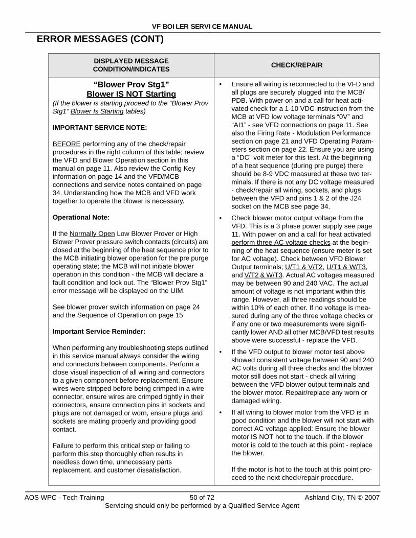
VF BOILER SERVICE MANUAL
ERROR MESSAGES (CONT)
DISPLAYED MESSAGECONDITION/INDICATES CHECK/REPAIR
“Blower Prov Stg1”Blower IS NOT Starting
(If the blower is starting proceed to the “Blower Prov Stg1” Blower Is Starting tables)
IMPORTANT SERVICE NOTE:
BEFORE performing any of the check/repair procedures in the right column of this table; review the VFD and Blower Operation section in this manual on page 11. Also review the Config Key information on page 14 and the VFD/MCB connections and service notes contained on page 34. Understanding how the MCB and VFD work together to operate the blower is necessary.
Operational Note:
If the Normally Open Low Blower Prover or High Blower Prover pressure switch contacts (circuits) are closed at the beginning of the heat sequence prior to the MCB initiating blower operation for the pre purge operating state; the MCB will not initiate blower operation in this condition - the MCB will declare a fault condition and lock out. The “Blower Prov Stg1” error message will be displayed on the UIM.
See blower prover switch information on page 24 and the Sequence of Operation on page 15
Important Service Reminder:
When performing any troubleshooting steps outlined in this service manual always consider the wiring and connectors between components. Perform a close visual inspection of all wiring and connectors to a given component before replacement. Ensure wires were stripped before being crimped in a wire connector, ensure wires are crimped tightly in their connectors, ensure connection pins in sockets and plugs are not damaged or worn, ensure plugs and sockets are mating properly and providing good contact.
Failure to perform this critical step or failing to perform this step thoroughly often results in needless down time, unnecessary parts replacement, and customer dissatisfaction.
• Ensure all wiring is reconnected to the VFD and all plugs are securely plugged into the MCB/PDB. With power on and a call for heat acti-vated check for a 1-10 VDC instruction from the MCB at VFD low voltage terminals “0V” and “AI1” - see VFD connections on page 11. See also the Firing Rate - Modulation Performance section on page 21 and VFD Operating Param-eters section on page 22. Ensure you are using a “DC” volt meter for this test. At the beginning of a heat sequence (during pre purge) there should be 8-9 VDC measured at these two ter-minals. If there is not any DC voltage measured - check/repair all wiring, sockets, and plugs between the VFD and pins 1 & 2 of the J24 socket on the MCB see page 34.
• Check blower motor output voltage from the VFD. This is a 3 phase power supply see page 11. With power on and a call for heat activated perform three AC voltage checks at the begin-ning of the heat sequence (ensure meter is set for AC voltage). Check between VFD Blower Output terminals; U/T1 & V/T2, U/T1 & W/T3, and V/T2 & W/T3. Actual AC voltages measured may be between 90 and 240 VAC. The actual amount of voltage is not important within this range. However, all three readings should be within 10% of each other. If no voltage is mea-sured during any of the three voltage checks or if any one or two measurements were signifi-cantly lower AND all other MCB/VFD test results above were successful - replace the VFD.
• If the VFD output to blower motor test above showed consistent voltage between 90 and 240 AC volts during all three checks and the blower motor still does not start - check all wiring between the VFD blower output terminals and the blower motor. Repair/replace any worn or damaged wiring.
• If all wiring to blower motor from the VFD is in good condition and the blower will not start with correct AC voltage applied: Ensure the blower motor IS NOT hot to the touch. If the blower motor is cold to the touch at this point - replace the blower.
If the motor is hot to the touch at this point pro-ceed to the next check/repair procedure.
AOS WPC - Tech Training 50 of 72 Ashland City, TN © 2007Servicing should only be performed by a Qualified Service Agent
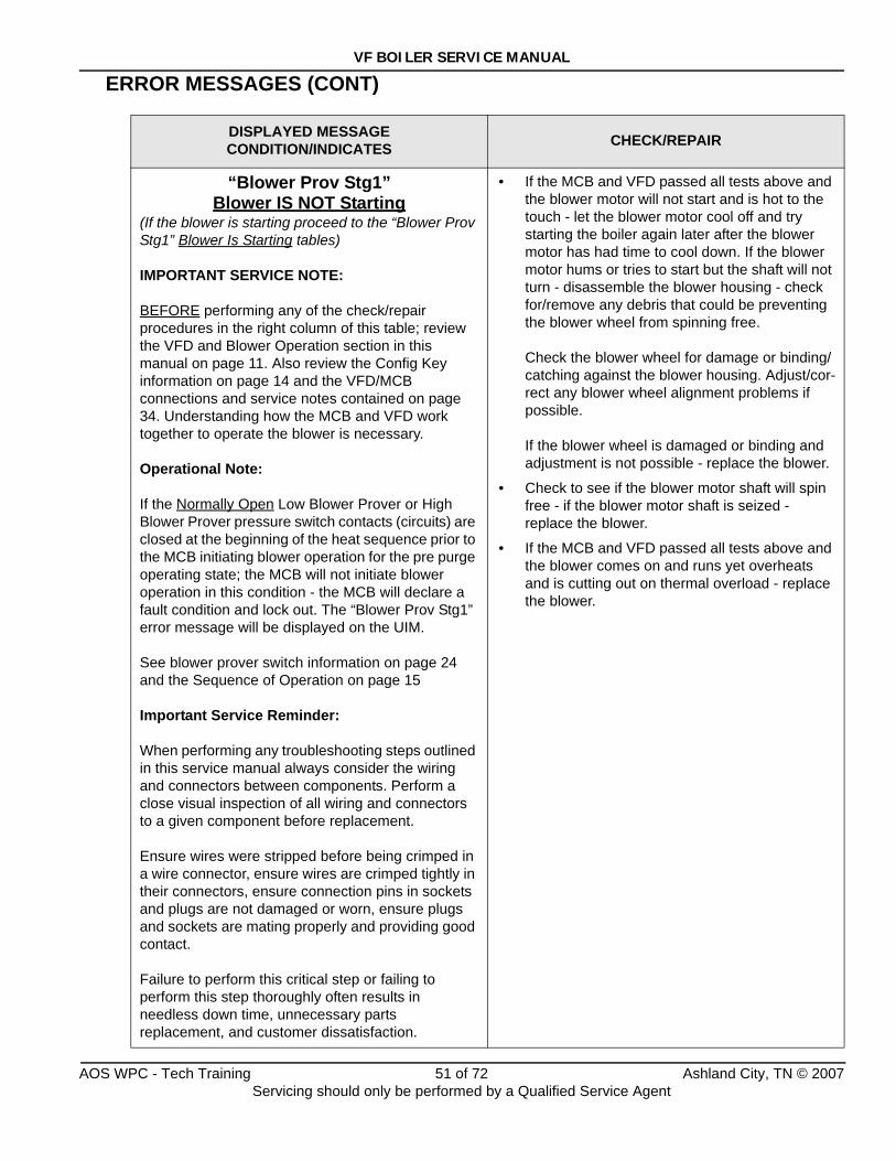
VF BOILER SERVICE MANUAL
ERROR MESSAGES (CONT)
DISPLAYED MESSAGECONDITION/INDICATES CHECK/REPAIR
“Blower Prov Stg1”Blower IS NOT Starting
(If the blower is starting proceed to the “Blower Prov Stg1” Blower Is Starting tables)
IMPORTANT SERVICE NOTE:
BEFORE performing any of the check/repair procedures in the right column of this table; review the VFD and Blower Operation section in this manual on page 11. Also review the Config Key information on page 14 and the VFD/MCB connections and service notes contained on page 34. Understanding how the MCB and VFD work together to operate the blower is necessary.
Operational Note:
If the Normally Open Low Blower Prover or High Blower Prover pressure switch contacts (circuits) are closed at the beginning of the heat sequence prior to the MCB initiating blower operation for the pre purge operating state; the MCB will not initiate blower operation in this condition - the MCB will declare a fault condition and lock out. The “Blower Prov Stg1” error message will be displayed on the UIM.
See blower prover switch information on page 24 and the Sequence of Operation on page 15
Important Service Reminder:
When performing any troubleshooting steps outlined in this service manual always consider the wiring and connectors between components. Perform a close visual inspection of all wiring and connectors to a given component before replacement.
Ensure wires were stripped before being crimped in a wire connector, ensure wires are crimped tightly in their connectors, ensure connection pins in sockets and plugs are not damaged or worn, ensure plugs and sockets are mating properly and providing good contact.
Failure to perform this critical step or failing to perform this step thoroughly often results in needless down time, unnecessary parts replacement, and customer dissatisfaction.
• If the MCB and VFD passed all tests above and the blower motor will not start and is hot to the touch - let the blower motor cool off and try starting the boiler again later after the blower motor has had time to cool down. If the blower motor hums or tries to start but the shaft will not turn - disassemble the blower housing - check for/remove any debris that could be preventing the blower wheel from spinning free.
Check the blower wheel for damage or binding/catching against the blower housing. Adjust/cor-rect any blower wheel alignment problems if possible.
If the blower wheel is damaged or binding and adjustment is not possible - replace the blower.
• Check to see if the blower motor shaft will spin free - if the blower motor shaft is seized - replace the blower.
• If the MCB and VFD passed all tests above and the blower comes on and runs yet overheats and is cutting out on thermal overload - replace the blower.
AOS WPC - Tech Training 51 of 72 Ashland City, TN © 2007Servicing should only be performed by a Qualified Service Agent
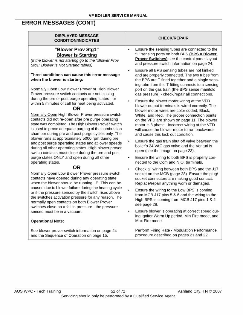
VF BOILER SERVICE MANUAL
ERROR MESSAGES (CONT)
DISPLAYED MESSAGECONDITION/INDICATES CHECK/REPAIR
“Blower Prov Stg1”Blower Is Starting
(If the blower is not starting go to the “Blower Prov Stg1” Blower Is Not Starting tables)
Three conditions can cause this error message when the blower is starting:
Normally Open Low Blower Prover or High Blower Prover pressure switch contacts are not closing during the pre or post purge operating states - or within 5 minutes of call for heat being activated.
ORNormally Open High Blower Prover pressure switch contacts did not re-open after pre purge operating state was completed. The High Blower Prover switch is used to prove adequate purging of the combustion chamber during pre and post purge cycles only. The blower runs at approximately 5000 rpm during pre and post purge operating states and at lower speeds during all other operating states. High blower prover switch contacts must close during the pre and post purge states ONLY and open during all other operating states.
ORNormally Open Low Blower Prover pressure switch contacts have opened during any operating state when the blower should be running. IE: This can be caused due to blower failure during the heating cycle or if the pressure sensed by the switch rises above the switches activation pressure for any reason. The normally open contacts on both Blower Prover switches close on a fall in pressure - the pressure sensed must be in a vacuum.
Operational Note:
See blower prover switch information on page 24 and the Sequence of Operation on page 15.
• Ensure the sensing tubes are connected to the “L” sensing ports on both BPS (BPS = Blower Prover Switches) see the control panel layout and pressure switch information on page 24.
• Ensure all BPS sensing tubes are not kinked and are properly connected. The two tubes from the BPS are T fitted together and a single sens-ing tube from this T fitting connects to a sensing port on the gas train (the BPS sense manifold gas pressure) - check/repair all connections.
• Ensure the blower motor wiring at the VFD blower output terminals is wired correctly. The blower motor wires are color coded; Black, White, and Red. The proper connection points on the VFD are shown on page 11. The blower motor is 3 phase - incorrect wiring at the VFD will cause the blower motor to run backwards and cause this lock out condition.
• Ensure the gas train shut off valve between the boiler’s 24 VAC gas valve and the Venturi is open (see the image on page 23).
• Ensure the wiring to both BPS is properly con-nected to the Com and N.O. terminals.
• Check all wiring between both BPS and the J17 socket on the MCB (page 28). Ensure the plug/socket connectors are making good contact. Replace/repair anything worn or damaged.
• Ensure the wiring to the Low BPS is coming from MCB J17 pins 5 & 6 and the wiring to the High BPS is coming from MCB J17 pins 1 & 2 see page 28.
• Ensure blower is operating at correct speed dur-ing Igniter Warm Up period, Min Fire mode, and Max Fire mode.
Perform Firing Rate - Modulation Performance procedure described on pages 21 and 22.
AOS WPC - Tech Training 52 of 72 Ashland City, TN © 2007Servicing should only be performed by a Qualified Service Agent
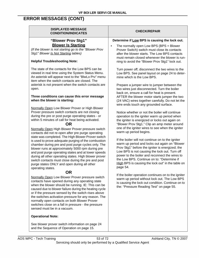
VF BOILER SERVICE MANUAL
ERROR MESSAGES (CONT)
DISPLAYED MESSAGECONDITION/INDICATES CHECK/REPAIR
“Blower Prov Stg1”Blower Is Starting
(If the blower is not starting go to the “Blower Prov Stg1” Blower Is Not Starting tables)
Helpful Troubleshooting Note:
The state of the contacts for the Low BPS can be viewed in real time using the System Status Menu. An asterisk will appear next to the “BlwLo Prv” menu item when the switch contacts are closed. The asterisk is not present when the switch contacts are open.
Three conditions can cause this error message when the blower is starting:
Normally Open Low Blower Prover or High Blower Prover pressure switch contacts are not closing during the pre or post purge operating states - or within 5 minutes of call for heat being activated.
ORNormally Open High Blower Prover pressure switch contacts did not re-open after pre purge operating state was completed. The High Blower Prover switch is used to prove adequate purging of the combustion chamber during pre and post purge cycles only. The blower runs at approximately 5000 rpm during pre and post purge operating states and at lower speeds during all other operating states. High blower prover switch contacts must close during the pre and post purge states ONLY and open during all other operating states.
ORNormally Open Low Blower Prover pressure switch contacts have opened during any operating state when the blower should be running. IE: This can be caused due to blower failure during the heating cycle or if the pressure sensed by the switch rises above the switches activation pressure for any reason. The normally open contacts on both Blower Prover switches close on a fall in pressure - the pressure sensed must be in a vacuum.
Operational Note:
See blower prover switch information on page 24 and the Sequence of Operation on page 15.
Determine if Low BPS is causing the lock out.• The normally open Low BPS (BPS = Blower
Prover Switch) switch must close its contacts after the blower starts. The Low BPS contacts must remain closed whenever the blower is run-ning to avoid the “Blower Prov Stg1” lock out.
Turn power off; disconnect the two wires to the Low BPS. See panel layout on page 24 to deter-mine which is the Low BPS.
Prepare a jumper wire to jumper between the two wires just disconnected. Turn the boiler back on, ensure a call for heat is present. AFTER the blower motor starts jumper the two (24 VAC) wires together carefully. Do not let the wire ends touch any grounded surface.
Notice whether or not the boiler will continue operation to the igniter warm up period when the igniter is energized or locks out again on “Blower Prov Stg1.” Clip an amp meter around one of the igniter wires to see when the igniter warm up period begins.
If the boiler will not continue on to the igniter warm up period and locks out again on “Blower Prov Stg1” before the igniter is energized; the Low BPS is not causing the lock out. Turn off power to the boiler and reconnect the wires to the Low BPS. Continue on to: “Determine if High BPS is causing the lock out” in the table on page 54.
If the boiler operation continues on to the igniter warm up period without lock out. The Low BPS is causing the lock out condition. Continue on to the: “Pressure Reading Test” on page 55.
AOS WPC - Tech Training 53 of 72 Ashland City, TN © 2007Servicing should only be performed by a Qualified Service Agent
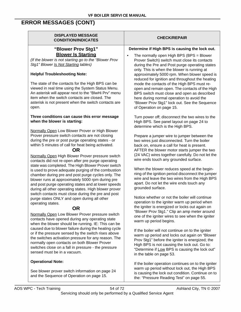
VF BOILER SERVICE MANUAL
ERROR MESSAGES (CONT)
DISPLAYED MESSAGECONDITION/INDICATES CHECK/REPAIR
“Blower Prov Stg1”Blower Is Starting
(If the blower is not starting go to the “Blower Prov Stg1” Blower Is Not Starting tables)
Helpful Troubleshooting Note:
The state of the contacts for the High BPS can be viewed in real time using the System Status Menu. An asterisk will appear next to the “BlwHi Prv” menu item when the switch contacts are closed. The asterisk is not present when the switch contacts are open.
Three conditions can cause this error message when the blower is starting:
Normally Open Low Blower Prover or High Blower Prover pressure switch contacts are not closing during the pre or post purge operating states - or within 5 minutes of call for heat being activated.
ORNormally Open High Blower Prover pressure switch contacts did not re-open after pre purge operating state was completed. The High Blower Prover switch is used to prove adequate purging of the combustion chamber during pre and post purge cycles only. The blower runs at approximately 5000 rpm during pre and post purge operating states and at lower speeds during all other operating states. High blower prover switch contacts must close during the pre and post purge states ONLY and open during all other operating states.
ORNormally Open Low Blower Prover pressure switch contacts have opened during any operating state when the blower should be running. IE: This can be caused due to blower failure during the heating cycle or if the pressure sensed by the switch rises above the switches activation pressure for any reason. The normally open contacts on both Blower Prover switches close on a fall in pressure - the pressure sensed must be in a vacuum.
Operational Note:
See blower prover switch information on page 24 and the Sequence of Operation on page 15.
Determine if High BPS is causing the lock out. • The normally open High BPS (BPS = Blower
Prover Switch) switch must close its contacts during the Pre and Post purge operating states only. This is when the blower is running at approximately 5000 rpm. When blower speed is reduced for ignition and throughout the heating mode the contacts of the High BPS must re-open and remain open. The contacts of the High BPS switch must close and open as described here during normal operation to avoid the “Blower Prov Stg1” lock out. See the Sequence of Operation on page 15.
Turn power off; disconnect the two wires to the High BPS. See panel layout on page 24 to determine which is the High BPS.
Prepare a jumper wire to jumper between the two wires just disconnected. Turn the boiler back on, ensure a call for heat is present. AFTER the blower motor starts jumper the two (24 VAC) wires together carefully. Do not let the wire ends touch any grounded surface.
When the blower reduces speed at the begin-ning of the ignition period disconnect the jumper wire and leave the two wires from the High BPS apart. Do not let the wire ends touch any grounded surface.
Notice whether or not the boiler will continue operation to the igniter warm up period when the igniter is energized or locks out again on “Blower Prov Stg1.” Clip an amp meter around one of the igniter wires to see when the igniter warm up period begins.
If the boiler will not continue on to the igniter warm up period and locks out again on “Blower Prov Stg1” before the igniter is energized; the High BPS is not causing the lock out. Go to: “Determine if Low BPS is causing the lock out” in the table on page 53.
If the boiler operation continues on to the igniter warm up period without lock out, the High BPS is causing the lock out condition. Continue on to the: “Pressure Reading Test” on page 55.
AOS WPC - Tech Training 54 of 72 Ashland City, TN © 2007Servicing should only be performed by a Qualified Service Agent
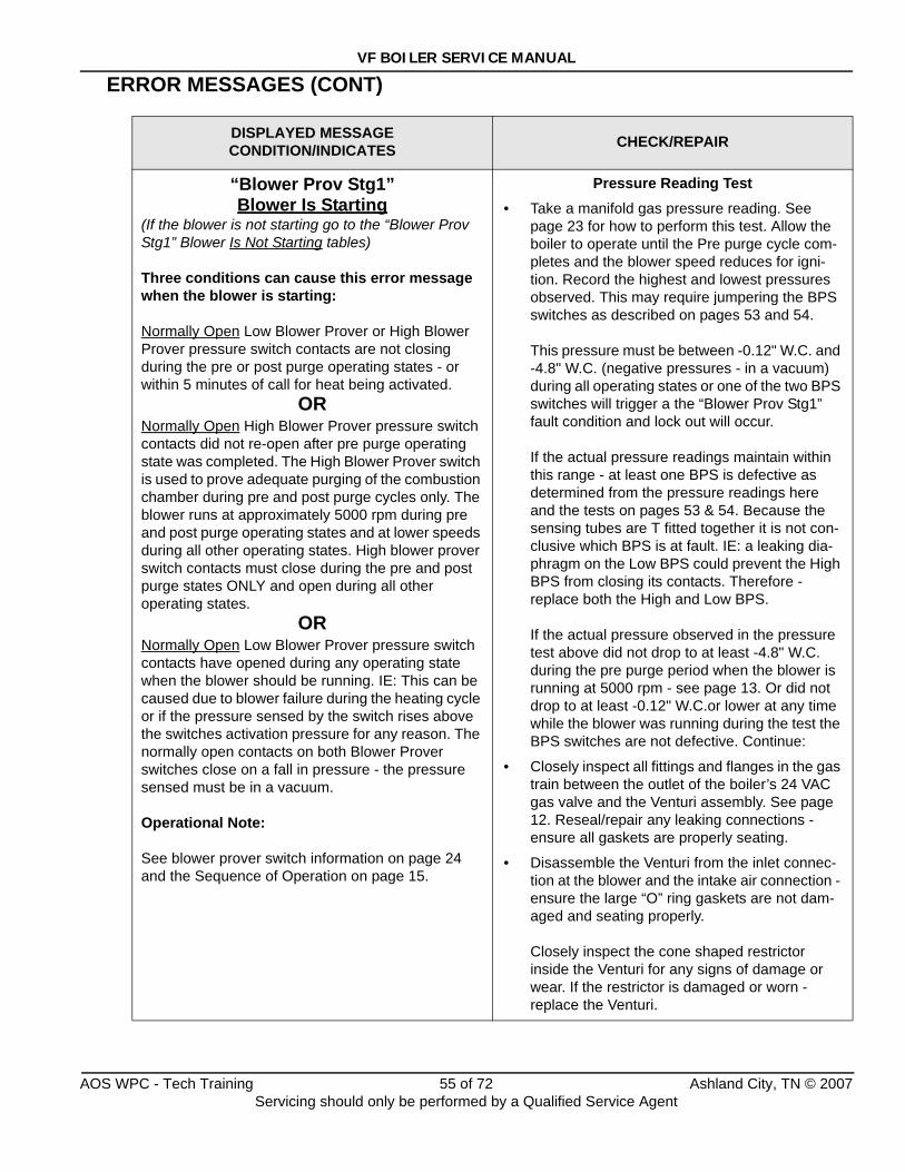
VF BOILER SERVICE MANUAL
ERROR MESSAGES (CONT)
DISPLAYED MESSAGECONDITION/INDICATES CHECK/REPAIR
“Blower Prov Stg1”Blower Is Starting
(If the blower is not starting go to the “Blower Prov Stg1” Blower Is Not Starting tables)
Three conditions can cause this error message when the blower is starting:
Normally Open Low Blower Prover or High Blower Prover pressure switch contacts are not closing during the pre or post purge operating states - or within 5 minutes of call for heat being activated.
ORNormally Open High Blower Prover pressure switch contacts did not re-open after pre purge operating state was completed. The High Blower Prover switch is used to prove adequate purging of the combustion chamber during pre and post purge cycles only. The blower runs at approximately 5000 rpm during pre and post purge operating states and at lower speeds during all other operating states. High blower prover switch contacts must close during the pre and post purge states ONLY and open during all other operating states.
ORNormally Open Low Blower Prover pressure switch contacts have opened during any operating state when the blower should be running. IE: This can be caused due to blower failure during the heating cycle or if the pressure sensed by the switch rises above the switches activation pressure for any reason. The normally open contacts on both Blower Prover switches close on a fall in pressure - the pressure sensed must be in a vacuum.
Operational Note:
See blower prover switch information on page 24 and the Sequence of Operation on page 15.
Pressure Reading Test • Take a manifold gas pressure reading. See
page 23 for how to perform this test. Allow the boiler to operate until the Pre purge cycle com-pletes and the blower speed reduces for igni-tion. Record the highest and lowest pressures observed. This may require jumpering the BPS switches as described on pages 53 and 54.
This pressure must be between -0.12" W.C. and -4.8" W.C. (negative pressures - in a vacuum) during all operating states or one of the two BPS switches will trigger a the “Blower Prov Stg1” fault condition and lock out will occur.
If the actual pressure readings maintain within this range - at least one BPS is defective as determined from the pressure readings here and the tests on pages 53 & 54. Because the sensing tubes are T fitted together it is not con-clusive which BPS is at fault. IE: a leaking dia-phragm on the Low BPS could prevent the High BPS from closing its contacts. Therefore - replace both the High and Low BPS.
If the actual pressure observed in the pressure test above did not drop to at least -4.8" W.C. during the pre purge period when the blower is running at 5000 rpm - see page 13. Or did not drop to at least -0.12" W.C.or lower at any time while the blower was running during the test the BPS switches are not defective. Continue:
• Closely inspect all fittings and flanges in the gas train between the outlet of the boiler’s 24 VAC gas valve and the Venturi assembly. See page 12. Reseal/repair any leaking connections - ensure all gaskets are properly seating.
• Disassemble the Venturi from the inlet connec-tion at the blower and the intake air connection - ensure the large “O” ring gaskets are not dam-aged and seating properly.
Closely inspect the cone shaped restrictor inside the Venturi for any signs of damage or wear. If the restrictor is damaged or worn - replace the Venturi.
AOS WPC - Tech Training 55 of 72 Ashland City, TN © 2007Servicing should only be performed by a Qualified Service Agent
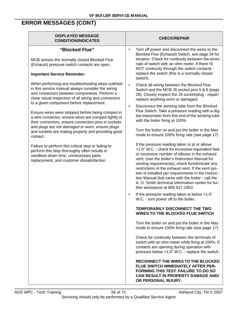
VF BOILER SERVICE MANUAL
ERROR MESSAGES (CONT)
DISPLAYED MESSAGECONDITION/INDICATES CHECK/REPAIR
“Blocked Flue”
MCB senses the normally closed Blocked Flue (Exhaust) pressure switch contacts are open.
Important Service Reminder:
When performing any troubleshooting steps outlined in this service manual always consider the wiring and connectors between components. Perform a close visual inspection of all wiring and connectors to a given component before replacement.
Ensure wires were stripped before being crimped in a wire connector, ensure wires are crimped tightly in their connectors, ensure connection pins in sockets and plugs are not damaged or worn, ensure plugs and sockets are mating properly and providing good contact.
Failure to perform this critical step or failing to perform this step thoroughly often results in needless down time, unnecessary parts replacement, and customer dissatisfaction.
• Turn off power and disconnect the wires to the Blocked Flue (Exhaust) Switch, see page 24 for location. Check for continuity between the termi-nals of switch with an ohm meter. If there IS NOT continuity through the switch contacts - replace the switch (this is a normally closed switch).
• Check all wiring between the Blocked Flue Switch and the MCB J5 socket pins 5 & 6 (page 28). Closely inspect the J5 socket/plug - repair/replace anything worn or damaged.
• Disconnect the sensing tube from the Blocked Flue Switch. Take a pressure reading with a dig-ital manometer from this end of the sensing tube with the boiler firing at 100%.
Turn the boiler on and put the boiler in the Max mode to ensure 100% firing rate (see page 17)
If the pressure reading taken is at or above +1.0” W.C. - check for excessive equivalent feet or excessive number of elbows in the exhaust vent, (see the boiler’s Instruction Manual for venting requirements), check for/eliminate any restrictions in the exhaust vent. If the vent sys-tem is installed per requirements in the Instruc-tion Manual that came with the boiler - call the A. O. Smith technical information center for fur-ther assistance at 800 527-1953
• If the pressure reading taken is below +1.0” W.C. - turn power off to the boiler.
TEMPORARILY DISCONNECT THE TWO WIRES TO THE BLOCKED FLUE SWITCH
Turn the boiler on and put the boiler in the Max mode to ensure 100% firing rate (see page 17)
Check for continuity between the terminals of switch with an ohm meter while firing at 100%. If contacts are opening during operation with pressure below +1.0" W.C. - replace the switch.
RECONNECT THE WIRES TO THE BLOCKED FLUE SWITCH IMMEDIATELY AFTER PER-FORMING THIS TEST. FAILURE TO DO SO CAN RESULT IN PROPERTY DAMAGE AND/OR PERSONAL INJURY.
AOS WPC - Tech Training 56 of 72 Ashland City, TN © 2007Servicing should only be performed by a Qualified Service Agent
VF BOILER SERVICE MANUAL
ERROR MESSAGES (CONT)
DISPLAYED MESSAGECONDITION/INDICATES CHECK/REPAIR
“Flame Stg1”
Flame or ignition failure.Error message displayed after 1 or 3 losses of flame or after 1 or 3 failed trials for ignition. EMC 5000 control system will lock-out after 1 or 3 trials depending on the SW1 #2 dip switch setting on the MCB circuit board. (see page 30)
Important Service Reminder:
When performing any troubleshooting steps outlined in this service manual always consider the wiring and connectors between components. Perform a close visual inspection of all wiring and connectors to a given component before replacement.
Ensure wires were stripped before being crimped in a wire connector, ensure wires are crimped tightly in their connectors, ensure connection pins in sockets and plugs are not damaged or worn, ensure plugs and sockets are mating properly and providing good contact.
Failure to perform this critical step or failing to perform this step thoroughly often results in needless down time, unnecessary parts replacement, and customer dissatisfaction.
• Ensure the supply gas shut off valve to the boiler and the gas train shut off valve (see image on page 23) are both open.
• Perform the Start Up Procedure pages 17-19.
• Perform the Poor Combustion/Ignition Problems procedures on pages 20-23.
• View the burner through the view port near the igniter on the top of the combustion chamber during the ignition trial period. If the burner is igniting but the flame goes out in a few seconds ensure the flame sensor wiring is connected properly and in good condition.
Note: There are two flame sensors on VF boil-ers. A single wire is connected to the J16 con-nect on the MCB (page 29). This wire is bifurcated (divided) into two wires and each end then connects to one of the two flame sensors. Repair/replace any worn or damaged wiring.
• If the flame sensor wiring is in good condition - perform a flame sensing test. Using a DC micro amp meter; place the meter test probes in series with the flame sensor wire. Disconnect the wire at the J16 connect on the MCB (page 29) insert the tip of one test probe into the wire connector securely - touch and hold the other test probe to the J16 connect.
Measure the flame sensing current during igni-tion. If the flame sensing current is less than 2.5 µA - remove, inspect, and clean both flame sen-sors. 5.0 µA flame sensing current is typical.
If either flame sensor shows signs of damage or the ceramic insulator is cracked - replace the flame sensor (s). If the flame sensors are in good condition clean both sensors with fine steel wool and reinstall both sensors. Check flame sensing current again to see if the current is higher and burner flame is established.
If the burner flame is still going out after a few seconds and all the above checks and proce-dures have been performed - call the A. O. Smith technical information center for further assistance at 800 527-1953.
AOS WPC - Tech Training 57 of 72 Ashland City, TN © 2007Servicing should only be performed by a Qualified Service Agent
VF BOILER SERVICE MANUAL
ERROR MESSAGES (CONT)
DISPLAYED MESSAGECONDITION/INDICATES CHECK/REPAIR
“Flame Stg1” (cont)
Flame or ignition failure.Error message displayed after 1 or 3 losses of flame or after 1 or 3 failed trials for ignition. EMC 5000 control system will lock-out after 1 or 3 trials depending on the SW1 #2 dip switch setting on the MCB circuit board. (see page 30)
Important Service Reminder:
When performing any troubleshooting steps outlined in this service manual always consider the wiring and connectors between components. Perform a close visual inspection of all wiring and connectors to a given component before replacement.
Ensure wires were stripped before being crimped in a wire connector, ensure wires are crimped tightly in their connectors, ensure connection pins in sockets and plugs are not damaged or worn, ensure plugs and sockets are mating properly and providing good contact.
Failure to perform this critical step or failing to perform this step thoroughly often results in needless down time, unnecessary parts replacement, and customer dissatisfaction.
• Check igniter amperage during igniter warm up period. If amp draw is less than 3.0 amps replace the igniter.
• Ensure the 1/8” steel sensing tube that connects between the gas valve (near the low fire adjust-ment screw cap) and the Venturi assembly is not clogged or damaged and properly con-nected at both ends. If the tube is kinked or damaged - replace the tube. Remove the steel tube and blow through it to ensure it is not clogged. Reinstall and tighten the compression fittings tightly at both ends.
• Ensure the 24 VAC gas valve is being energized during ignition:
If the burner is failing to ignite when viewed through the view port on the top of the heat exchanger - check for 24 VAC between pins 1 & 2 of the J19 socket on the MCB (page 28) at the end of the igniter warm up period. If 24 VAC is present - check all wiring between the J19 socket and the gas valve. Check the J19 socket/plug pins for wear or damage. Check the ground (green) wire from gas valve coil to the ground connections in the junction box on the boiler - repair/replace anything worn or damaged.
If 24 VAC is not present between pins 1 & 2 of the J19 socket on the MCB - call the A. O. Smith technical information center for further assis-tance at 800 527-1953.
AOS WPC - Tech Training 58 of 72 Ashland City, TN © 2007Servicing should only be performed by a Qualified Service Agent
VF BOILER SERVICE MANUAL
ERROR MESSAGES (CONT)
DISPLAYED MESSAGECONDITION/INDICATES CHECK/REPAIR
“Flame Stg1” (cont)
Flame or ignition failure.Error message displayed after 1 or 3 losses of flame or after 1 or 3 failed trials for ignition. EMC 5000 control system will lock-out after 1 or 3 trials depending on the SW1 #2 dip switch setting on the MCB circuit board. (see page 30)
Important Service Reminder:
When performing any troubleshooting steps outlined in this service manual always consider the wiring and connectors between components. Perform a close visual inspection of all wiring and connectors to a given component before replacement.
Ensure wires were stripped before being crimped in a wire connector, ensure wires are crimped tightly in their connectors, ensure connection pins in sockets and plugs are not damaged or worn, ensure plugs and sockets are mating properly and providing good contact.
Failure to perform this critical step or failing to perform this step thoroughly often results in needless down time, unnecessary parts replacement, and customer dissatisfaction.
• Ensure the 24 VAC gas valve is opening and gas is flowing through the valve:
Secure power to the boiler. Remove the gas pressure test plug at the outlet of the boiler’s 24 VAC gas valve. Install a barbed hose adapter fit-ting in this test port. Connect a U-tube or digital manometer to the barbed fitting.
Close the gas train shut off valve (see image on page 23).
Turn power to the boiler back on - ensure there is a call for heat present.
The blower will reduce speed as the igniter warm up period begins. The gas valve is ener-gized at the end of the igniter warm up period.
When the gas valve is energized a positive pressure should be measured from the outlet test port on the boiler’s 24 VAC gas valve (with the gas train shut off valve closed). The mea-sured pressure should be approximately the same as supply gas pressure to the inlet of the valve.
If there is no pressure increase when perform-ing this test. Turn power to the boiler off. Close the supply gas shut off valve to the boiler and remove the boiler’s 24 VAC gas valve - clean/remove any obstructions or debris from the inlet and outlet of the gas valve. Ensure the supply gas line to the boiler and the gas train inside the boiler are not obstructed - clean/remove any obstructions or debris.
If the gas valve is being energized (previous page) and all the above tests have been per-formed and there is no gas pressure increase at the gas valve outlet during this test - call the A. O. Smith technical information center for further assistance at 800 527-1953.
REMEMBER TO RE-OPEN THE GAS TRAIN SHUT OFF VALVE.
AOS WPC - Tech Training 59 of 72 Ashland City, TN © 2007Servicing should only be performed by a Qualified Service Agent
VF BOILER SERVICE MANUAL
ERROR MESSAGES (CONT)
DISPLAYED MESSAGECONDITION/INDICATES CHECK/REPAIR
“Igniter Stg1”
MCB is not sensing minimum igniter current of 2.7 AC amps during the igniter warm up period.
Important Service Reminder:
When performing any troubleshooting steps outlined in this service manual always consider the wiring and connectors between components. Perform a close visual inspection of all wiring and connectors to a given component before replacement.
Ensure wires were stripped before being crimped in a wire connector, ensure wires are crimped tightly in their connectors, ensure connection pins in sockets and plugs are not damaged or worn, ensure plugs and sockets are mating properly and providing good contact.
Failure to perform this critical step or failing to perform this step thoroughly often results in needless down time, unnecessary parts replacement, and customer dissatisfaction.
• Check all wiring and connections between pins 1 & 2 of the J18 socket on the MCB (see page 29) and the igniter. Repair/replace any worn or damaged wiring or connectors.
Closely inspect the pins in the J18 socket/plug for wear or damage. Ensure the plug and socket are properly connected and making good con-tact.
• Ensure there is 120 VAC between pins 1 & 2 of the J18 socket on the MCB during the igniter warm up period (blower speed reduces after pre purge cycle is completed).
If 120 VAC is not present at the J18 socket dur-ing the igniter warm up period - call the A. O. Smith technical information center for further assistance at 800 527-1953.
• Check igniter amps during igniter warm up period (blower speed reduces after pre purge cycle is completed). If amp draw is less than 3.0 amps replace the igniter.
AOS WPC - Tech Training 60 of 72 Ashland City, TN © 2007Servicing should only be performed by a Qualified Service Agent
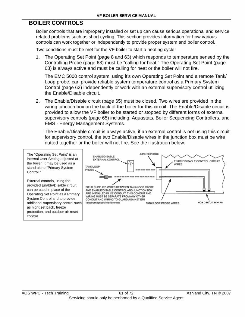
VF BOILER SERVICE MANUAL
BOILER CONTROLSBoiler controls that are improperly installed or set up can cause serious operational and service related problems such as short cycling. This section provides information for how various controls can work together or independently to provide proper system and boiler control.Two conditions must be met for the VF boiler to start a heating cycle:1. The Operating Set Point (page 8 and 63) which responds to temperature sensed by the
Controlling Probe (page 63) must be “calling for heat.” The Operating Set Point (page 63) is always active and must be calling for heat or the boiler will not fire.
The EMC 5000 control system, using it’s own Operating Set Point and a remote Tank/Loop probe, can provide reliable system temperature control as a Primary System Control (page 62) independently or work with an external supervisory control utilizing the Enable/Disable circuit.
2. The Enable/Disable circuit (page 65) must be closed. Two wires are provided in the wiring junction box on the back of the boiler for this circuit. The Enable/Disable circuit is provided to allow the VF boiler to be started or stopped by different forms of external supervisory controls (page 65) including: Aquastats, Boiler Sequencing Controllers, and EMS - Energy Management Systems.
The Enable/Disable circuit is always active, if an external control is not using this circuit for supervisory control, the two Enable/Disable wires in the junction box must be wire nutted together or the boiler will not fire. See the illustration below.
The “Operating Set Point” is an internal User Setting adjusted at the boiler. It may be used as a stand alone “Primary System Control.”
External controls, using the provided Enable/Disable circuit, can be used in place of the Operating Set Point as a Primary System Control and to provide additional supervisory control such as night set back, freeze protection, and outdoor air reset control.
MCB CIRCUIT BOARD
AOS WPC - Tech Training 61 of 72 Ashland City, TN © 2007Servicing should only be performed by a Qualified Service Agent
VF BOILER SERVICE MANUAL
BOILER CONTROLS (CONT)
Primary System ControlA Primary System Control is a top level “system” temperature control. A Primary System Control activates the call for heat or enables boiler operation when system temperature falls below the control’s set point and deactivates a call for heat or disables the boiler when system temperature reaches set point. The “system” is typically a storage tank (domestic hot water supply) or a hydronic loop (building heat system).
The Primary System Control must be able to sense temperature conditions in the system to work properly. It must not be adversely affected by false heat such as heat added by multiple boilers upstream or a bypass line.
The Primary System Control can be the Operating Set Point on the boiler acting on temperature sensed by the factory supplied remote Tank/Loop probe; the “Controlling Probe.” The Primary System Control can also be an External Temperature Control; a separate mechanical or electronic device that will have it’s own system temperature sensor (s) and a set of dry contacts to close or open the boiler’s Enable/Disable circuit.
Temperature ProbesThe temperature probes (3) used by the EMC 5000 control system are thermistors. Thermistors are thermally sensitive resistors. A change in temperature causes a corresponding change in electrical resistance (ohms). The EMC 5000 control system interprets the probe resistance as temperature.
VF boilers have two factory installed temperature probes; an Inlet Probe and an Outlet Probe to monitor the inlet and outlet water temperatures.
VF boilers are shipped from the factory with a third probe; the remote Tank/Loop Probe.
Remote Tank/Loop ProbeInstallation/Configuration: Remote Tank/Loop probes are furnished with VF boilers and should be installed in the storage tank on domestic hot water systems or in a T fitting in the return line before the boiler’s inlet on heating systems. On multiple boiler systems all Tank/Loop probes must be installed in T fittings before the first boiler’s inlet.
Two wires are provided for the Tank/Loop Probe in the junction box on the back of the boiler. Dedicated conduits must be provided for the field installed wiring to each Tank/Loop probe (page 68).
The SW1 dip switch #4 on the MCB (page 30) must be turned “on” to configure the remote Tank/Loop probe as the Controlling Probe (page 63).
Application Note: If the MCB SW1 dip switch #4 is turned off the control system will use the Inlet probe as the Controlling Probe; reliable system temperature control will not be possible.
Service Note: If the MCB SW1 dip switch #4 is turned on and the Tank/Loop Probe is not connected to the designated wires in the junction box on the back of the boiler the EMC 5000 control will declare a Tank Probe failure/fault condition and lock out. The “Tank Probe” error message will be displayed.
AOS WPC - Tech Training 62 of 72 Ashland City, TN © 2007Servicing should only be performed by a Qualified Service Agent
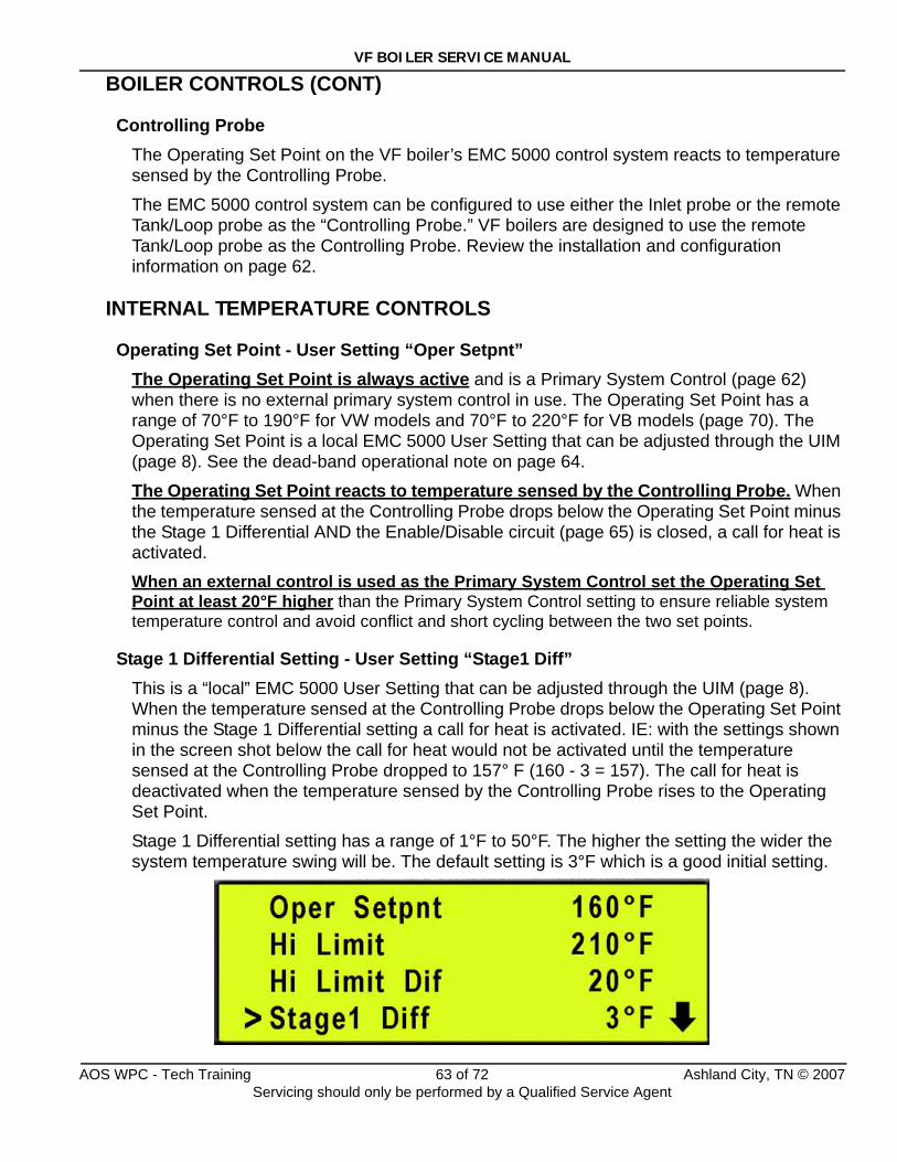
VF BOILER SERVICE MANUAL
BOILER CONTROLS (CONT)
Controlling ProbeThe Operating Set Point on the VF boiler’s EMC 5000 control system reacts to temperature sensed by the Controlling Probe.
The EMC 5000 control system can be configured to use either the Inlet probe or the remote Tank/Loop probe as the “Controlling Probe.” VF boilers are designed to use the remote Tank/Loop probe as the Controlling Probe. Review the installation and configuration information on page 62.
INTERNAL TEMPERATURE CONTROLS
Operating Set Point - User Setting “Oper Setpnt”The Operating Set Point is always active and is a Primary System Control (page 62) when there is no external primary system control in use. The Operating Set Point has a range of 70°F to 190°F for VW models and 70°F to 220°F for VB models (page 70). The Operating Set Point is a local EMC 5000 User Setting that can be adjusted through the UIM (page 8). See the dead-band operational note on page 64.
The Operating Set Point reacts to temperature sensed by the Controlling Probe. When the temperature sensed at the Controlling Probe drops below the Operating Set Point minus the Stage 1 Differential AND the Enable/Disable circuit (page 65) is closed, a call for heat is activated.When an external control is used as the Primary System Control set the Operating Set Point at least 20°F higher than the Primary System Control setting to ensure reliable system temperature control and avoid conflict and short cycling between the two set points.
Stage 1 Differential Setting - User Setting “Stage1 Diff”This is a “local” EMC 5000 User Setting that can be adjusted through the UIM (page 8). When the temperature sensed at the Controlling Probe drops below the Operating Set Point minus the Stage 1 Differential setting a call for heat is activated. IE: with the settings shown in the screen shot below the call for heat would not be activated until the temperature sensed at the Controlling Probe dropped to 157° F (160 - 3 = 157). The call for heat is deactivated when the temperature sensed by the Controlling Probe rises to the Operating Set Point.
Stage 1 Differential setting has a range of 1°F to 50°F. The higher the setting the wider the system temperature swing will be. The default setting is 3°F which is a good initial setting.
AOS WPC - Tech Training 63 of 72 Ashland City, TN © 2007Servicing should only be performed by a Qualified Service Agent
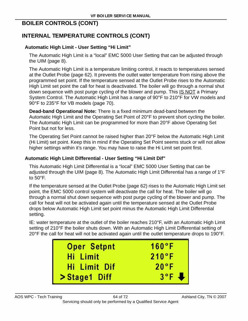
VF BOILER SERVICE MANUAL
BOILER CONTROLS (CONT)
INTERNAL TEMPERATURE CONTROLS (CONT)
Automatic High Limit - User Setting “Hi Limit”The Automatic High Limit is a “local” EMC 5000 User Setting that can be adjusted through the UIM (page 8).
The Automatic High Limit is a temperature limiting control, it reacts to temperatures sensed at the Outlet Probe (page 62). It prevents the outlet water temperature from rising above the programmed set point. If the temperature sensed at the Outlet Probe rises to the Automatic High Limit set point the call for heat is deactivated. The boiler will go through a normal shut down sequence with post purge cycling of the blower and pump. This IS NOT a Primary System Control. The Automatic High Limit has a range of 90°F to 210°F for VW models and 90°F to 235°F for VB models (page 70).
Dead-band Operational Note: There is a fixed minimum dead-band between the Automatic High Limit and the Operating Set Point of 20°F to prevent short cycling the boiler. The Automatic High Limit can be programmed for more than 20°F above Operating Set Point but not for less.
The Operating Set Point cannot be raised higher than 20°F below the Automatic High Limit (Hi Limit) set point. Keep this in mind if the Operating Set Point seems stuck or will not allow higher settings within it’s range. You may have to raise the Hi Limit set point first.
Automatic High Limit Differential - User Setting “Hi Limit Dif”This Automatic High Limit Differential is a “local” EMC 5000 User Setting that can be adjusted through the UIM (page 8). The Automatic High Limit Differential has a range of 1°F to 50°F.
If the temperature sensed at the Outlet Probe (page 62) rises to the Automatic High Limit set point, the EMC 5000 control system will deactivate the call for heat. The boiler will go through a normal shut down sequence with post purge cycling of the blower and pump. The call for heat will not be activated again until the temperature sensed at the Outlet Probe drops below Automatic High Limit set point minus the Automatic High Limit Differential setting.
IE: water temperature at the outlet of the boiler reaches 210°F, with an Automatic High Limit setting of 210°F the boiler shuts down. With an Automatic High Limit Differential setting of 20°F the call for heat will not be activated again until the outlet temperature drops to 190°F.
AOS WPC - Tech Training 64 of 72 Ashland City, TN © 2007Servicing should only be performed by a Qualified Service Agent
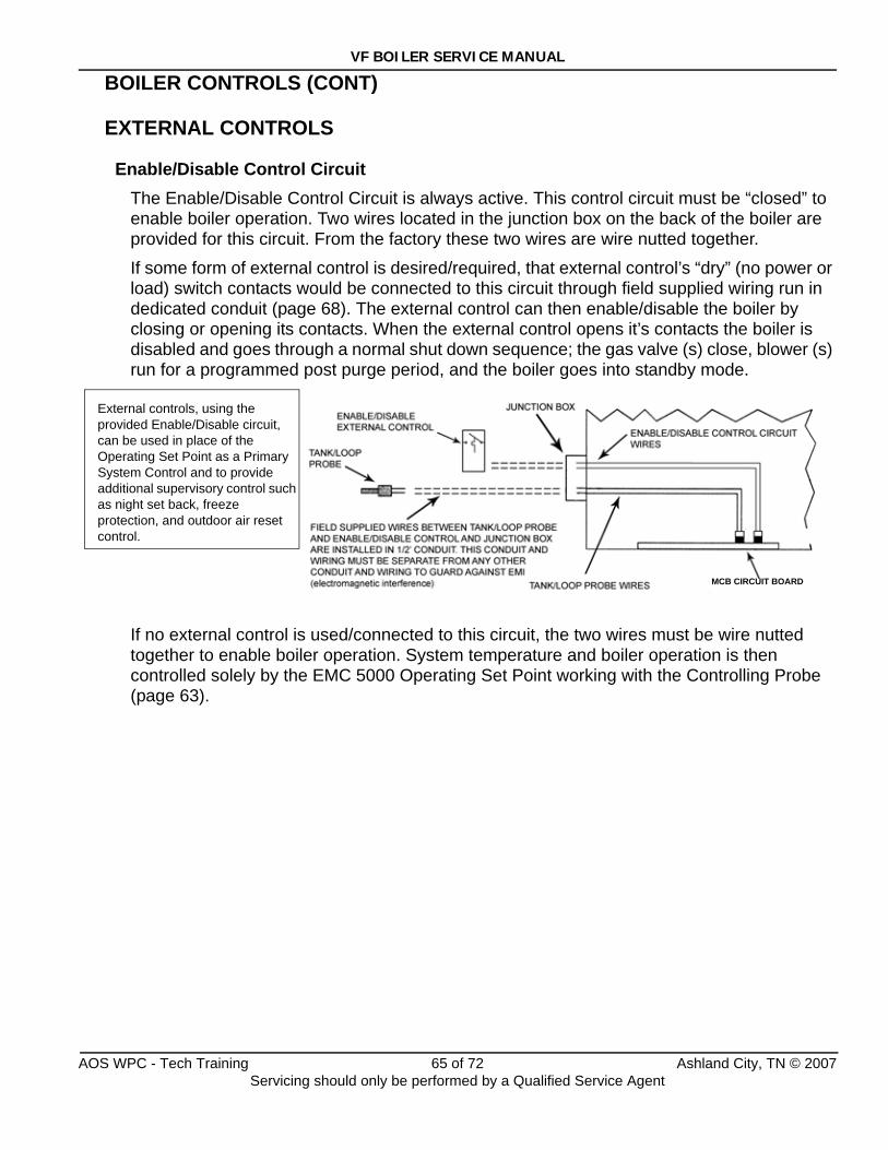
VF BOILER SERVICE MANUAL
BOILER CONTROLS (CONT)
EXTERNAL CONTROLS
Enable/Disable Control CircuitThe Enable/Disable Control Circuit is always active. This control circuit must be “closed” to enable boiler operation. Two wires located in the junction box on the back of the boiler are provided for this circuit. From the factory these two wires are wire nutted together.
If some form of external control is desired/required, that external control’s “dry” (no power or load) switch contacts would be connected to this circuit through field supplied wiring run in dedicated conduit (page 68). The external control can then enable/disable the boiler by closing or opening its contacts. When the external control opens it’s contacts the boiler is disabled and goes through a normal shut down sequence; the gas valve (s) close, blower (s) run for a programmed post purge period, and the boiler goes into standby mode.
If no external control is used/connected to this circuit, the two wires must be wire nutted together to enable boiler operation. System temperature and boiler operation is then controlled solely by the EMC 5000 Operating Set Point working with the Controlling Probe (page 63).
External controls, using the provided Enable/Disable circuit, can be used in place of the Operating Set Point as a Primary System Control and to provide additional supervisory control such as night set back, freeze protection, and outdoor air reset control.
MCB CIRCUIT BOARD
AOS WPC - Tech Training 65 of 72 Ashland City, TN © 2007Servicing should only be performed by a Qualified Service Agent
VF BOILER SERVICE MANUAL
BOILER CONTROLS (CONT)
EXTERNAL CONTROLS (CONT)
Types of External ControlsAn External Control can be a Primary System Control or a Supervisory Control or both. The enable/disable circuit described on page 65 would be field wired to the external control’s dry contacts. Field control wiring must be installed in a dedicated conduit.
When an external control is used as a Primary System Control the Operating Set Point on the boiler (pages 8 and 63) must be set at least 20°F higher than the external control’s temperature setting. This prevents the boiler’s Operating Set Point from cycling the boiler off before the Primary System Control’s Set Point has been reached (short-cycling the boiler).
Aquastat is one form of an external Primary System Control. A simple mechanical thermostat installed in a storage tank (domestic water) or in a T fitting on a heating loop (heating system).
EMS (energy management system) is another type of external Primary System Control. EMS controls can also provide supervisory enable/disable functionality. System temperature can be controlled by an EMS control equipped with it’s own Tank /Loop temperature sensor. Supervisory functionality such as occupied/unoccupied and/or freeze protection can be programmed in EMS systems to enable or disable boiler operation based on temperature, time, and event programing.
Outdoor Air Reset Control is another functionality EMS controllers often provide. The EMS system will have an outdoor temperature sensor or external load sensor in addition to a system temperature sensor. Typical Hydronic Reset Control operation; as the outdoor temperature drops, the system set point is automatically raised to provide more heating capacity as the load increases. As the outdoor temperature rises, the system set point is automatically lowered to provide energy savings during low load conditions.
Boiler Sequencing Controllers are another type of external control that can sequence multiple boilers on and off as the system load fluctuates using their own Tank or Loop temperature sensing device. These types of controls offer lead/lag operation of multiple boilers to provide equal run time rotation (also available in many EMS controllers) which evens the wear on all boilers over time. Many boiler sequence controllers are also available with Outdoor Air Reset Control functionality described above.
Multiple Boiler ControlEMS or Boiler Sequencing Controllers are strongly recommend in multiple boiler applications.
AOS WPC - Tech Training 66 of 72 Ashland City, TN © 2007Servicing should only be performed by a Qualified Service Agent
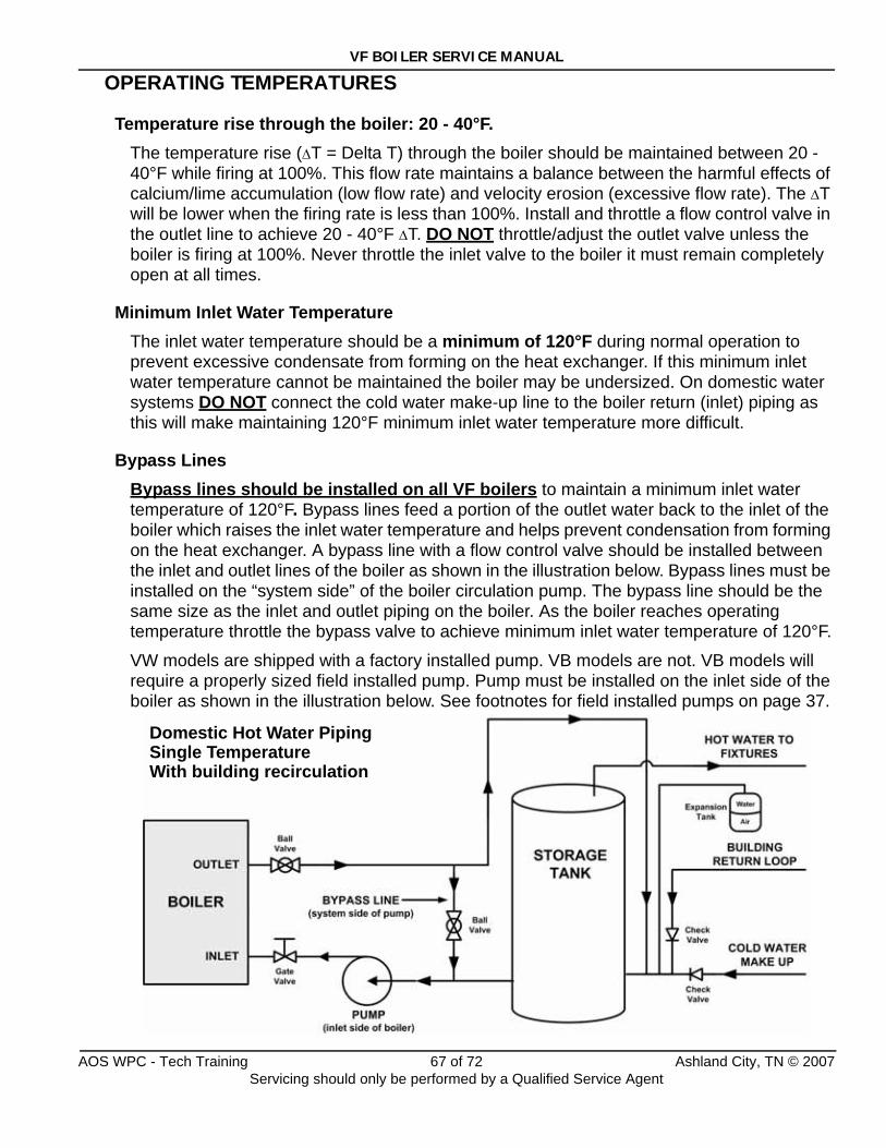
VF BOILER SERVICE MANUAL
OPERATING TEMPERATURES
Temperature rise through the boiler: 20 - 40°F. The temperature rise (ΔT = Delta T) through the boiler should be maintained between 20 - 40°F while firing at 100%. This flow rate maintains a balance between the harmful effects of calcium/lime accumulation (low flow rate) and velocity erosion (excessive flow rate). The ΔT will be lower when the firing rate is less than 100%. Install and throttle a flow control valve in the outlet line to achieve 20 - 40°F ΔT. DO NOT throttle/adjust the outlet valve unless the boiler is firing at 100%. Never throttle the inlet valve to the boiler it must remain completely open at all times.
Minimum Inlet Water TemperatureThe inlet water temperature should be a minimum of 120°F during normal operation to prevent excessive condensate from forming on the heat exchanger. If this minimum inlet water temperature cannot be maintained the boiler may be undersized. On domestic water systems DO NOT connect the cold water make-up line to the boiler return (inlet) piping as this will make maintaining 120°F minimum inlet water temperature more difficult.
Bypass LinesBypass lines should be installed on all VF boilers to maintain a minimum inlet water temperature of 120°F. Bypass lines feed a portion of the outlet water back to the inlet of the boiler which raises the inlet water temperature and helps prevent condensation from forming on the heat exchanger. A bypass line with a flow control valve should be installed between the inlet and outlet lines of the boiler as shown in the illustration below. Bypass lines must be installed on the “system side” of the boiler circulation pump. The bypass line should be the same size as the inlet and outlet piping on the boiler. As the boiler reaches operating temperature throttle the bypass valve to achieve minimum inlet water temperature of 120°F.
VW models are shipped with a factory installed pump. VB models are not. VB models will require a properly sized field installed pump. Pump must be installed on the inlet side of the boiler as shown in the illustration below. See footnotes for field installed pumps on page 37.
Domestic Hot Water PipingSingle Temperature With building recirculation
AOS WPC - Tech Training 67 of 72 Ashland City, TN © 2007Servicing should only be performed by a Qualified Service Agent
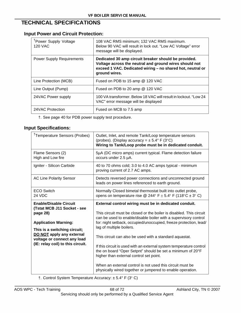
VF BOILER SERVICE MANUAL
TECHNICAL SPECIFICATIONS
Input Power and Circuit Protection:
Input Specifications:
†Power Supply Voltage120 VAC
†. See page 40 for PDB power supply test procedure.
108 VAC RMS minimum; 132 VAC RMS maximum. Below 90 VAC will result in lock out. “Low AC Voltage” error message will be displayed.
Power Supply Requirements Dedicated 30 amp circuit breaker should be provided. Voltage across the neutral and ground wires should not exceed 1 VAC. Dedicated wiring – no shared hot, neutral or ground wires.
Line Protection (MCB) Fused on PDB to 15 amp @ 120 VAC
Line Output (Pump) Fused on PDB to 20 amp @ 120 VAC
24VAC Power supply 100 VA transformer. Below 18 VAC will result in lockout. “Low 24 VAC” error message will be displayed
24VAC Protection Fused on MCB to 7.5 amp
†Temperature Sensors (Probes)
†. Control System Temperature Accuracy: ± 5.4° F (3° C)
Outlet, Inlet, and remote Tank/Loop temperature sensors (probes). (Display accuracy = ± 5.4° F (3°C) Wiring to Tank/Loop probe must be in dedicated conduit.
Flame Sensors (2)High and Low fire
5µA (DC micro amps) current typical. Flame detection failure occurs under 2.5 µA.
Igniter - Silicon Carbide 40 to 70 ohms cold; 3.0 to 4.0 AC amps typical - minimum proving current of 2.7 AC amps.
AC Line Polarity Sensor Detects reversed power connections and unconnected ground leads on power lines referenced to earth ground.
ECO Switch24 VDC
Normally Closed bimetal thermostat built into outlet probe, opens on temperature rise @ 244° F ± 5.4° F (118°C ± 3° C)
Enable/Disable Circuit(Tstat MCB J11 Socket - see page 28)
Application Warning:
This is a switching circuit; DO NOT apply any external voltage or connect any load (IE: relay coil) to this circuit.
External control wiring must be in dedicated conduit.
This circuit must be closed or the boiler is disabled. This circuit can be used to enable/disable boiler with a supervisory control for: night setback, occupied/unoccupied, freeze protection, lead/lag of multiple boilers.
This circuit can also be used with a standard aquastat.
If this circuit is used with an external system temperature control the on board “Oper Setpnt” should be set a minimum of 20°F higher than external control set point.
When an external control is not used this circuit must be physically wired together or jumpered to enable operation.
AOS WPC - Tech Training 68 of 72 Ashland City, TN © 2007Servicing should only be performed by a Qualified Service Agent
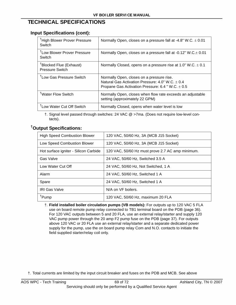
VF BOILER SERVICE MANUAL
TECHNICAL SPECIFICATIONS
Input Specifications (cont):
†Output Specifications:
†High Blower Prover Pressure Switch
†. Signal level passed through switches: 24 VAC @ >7ma. (Does not require low-level con-tacts).
Normally Open, closes on a pressure fall at -4.8" W.C. ± 0.01
†Low Blower Prover Pressure Switch
Normally Open, closes on a pressure fall at -0.12" W.C.± 0.01
†Blocked Flue (Exhaust) Pressure Switch
Normally Closed, opens on a pressure rise at 1.0" W.C. ± 0.1
†Low Gas Pressure Switch Normally Open, closes on a pressure rise.Natural Gas Activation Pressure: 4.0" W.C. ± 0.4 Propane Gas Activation Pressure: 6.4 " W.C. ± 0.5
†Water Flow Switch Normally Open, closes when flow rate exceeds an adjustable setting (approximately 22 GPM)
†Low Water Cut Off Switch Normally Closed, opens when water level is low
High Speed Combustion Blower 120 VAC, 50/60 Hz, 3A (MCB J15 Socket)
Low Speed Combustion Blower 120 VAC, 50/60 Hz, 3A (MCB J15 Socket)
Hot surface igniter - Silicon Carbide 120 VAC, 50/60 Hz must prove 2.7 AC amp minimum.
Gas Valve 24 VAC, 50/60 Hz, Switched 3.5 A
Low Water Cut Off 24 VAC, 50/60 Hz, Not Switched, 1 A
Alarm 24 VAC, 50/60 Hz, Switched 1 A
Spare 24 VAC, 50/60 Hz, Switched 1 A
IRI Gas Valve N/A on VF boilers.†Pump
†. Field installed boiler circulation pumps (VB models): For outputs up to 120 VAC 5 FLA use on board remote pump relay connected to TB1 terminal board on the PDB (page 36). For 120 VAC outputs between 5 and 20 FLA, use an external relay/starter and supply 120 VAC pump power through the 20 amp F2 pump fuse on the PDB (page 37). For outputs above 120 VAC or 20 FLA use an external relay/starter and a separate dedicated power supply for the pump, use the on board pump relay Com and N.O. contacts to initiate the field supplied starter/relay coil only.
120 VAC, 50/60 Hz, maximum 20 FLA
†. Total currents are limited by the input circuit breaker and fuses on the PDB and MCB. See above
AOS WPC - Tech Training 69 of 72 Ashland City, TN © 2007Servicing should only be performed by a Qualified Service Agent
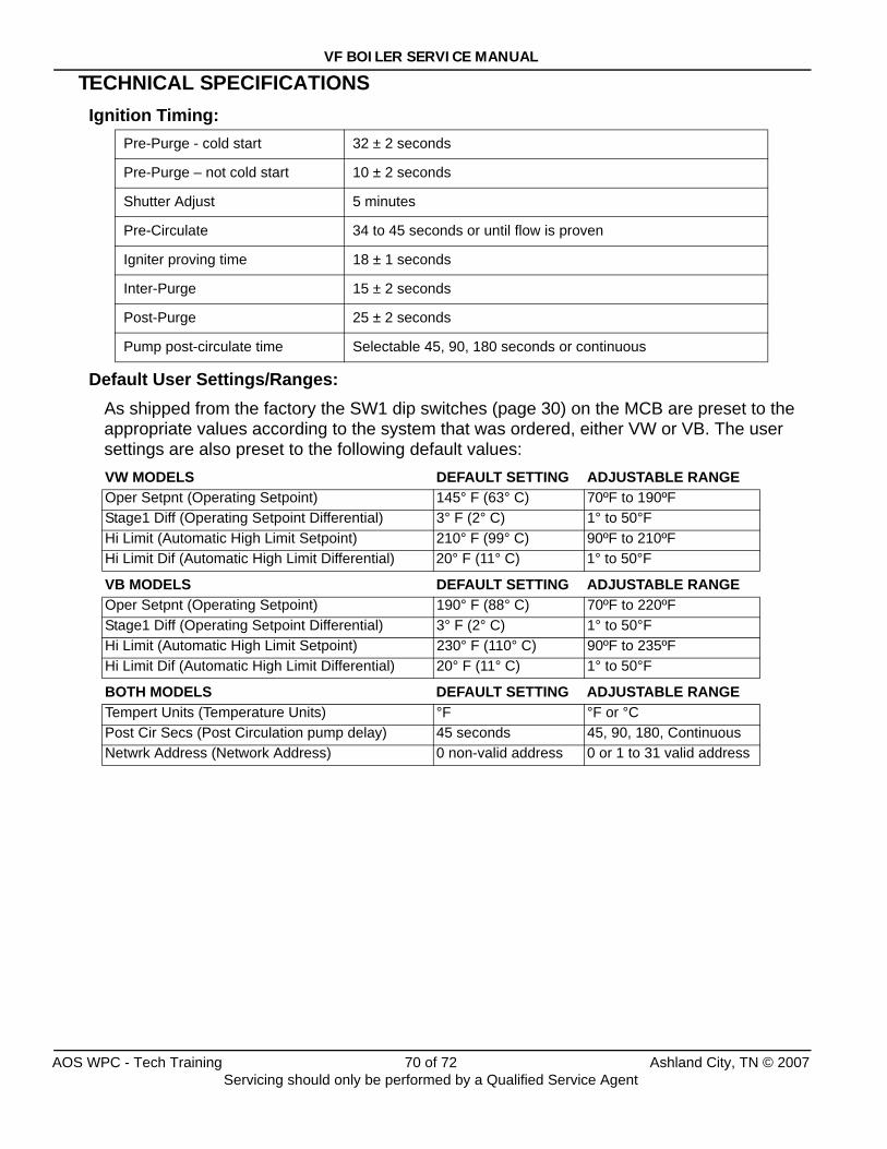
VF BOILER SERVICE MANUAL
TECHNICAL SPECIFICATIONSIgnition Timing:
Default User Settings/Ranges:As shipped from the factory the SW1 dip switches (page 30) on the MCB are preset to the appropriate values according to the system that was ordered, either VW or VB. The user settings are also preset to the following default values:
Pre-Purge - cold start 32 ± 2 seconds
Pre-Purge – not cold start 10 ± 2 seconds
Shutter Adjust 5 minutes
Pre-Circulate 34 to 45 seconds or until flow is proven
Igniter proving time 18 ± 1 seconds
Inter-Purge 15 ± 2 seconds
Post-Purge 25 ± 2 seconds
Pump post-circulate time Selectable 45, 90, 180 seconds or continuous
VW MODELS DEFAULT SETTING ADJUSTABLE RANGEOper Setpnt (Operating Setpoint) 145° F (63° C) 70ºF to 190ºFStage1 Diff (Operating Setpoint Differential) 3° F (2° C) 1° to 50°FHi Limit (Automatic High Limit Setpoint) 210° F (99° C) 90ºF to 210ºF Hi Limit Dif (Automatic High Limit Differential) 20° F (11° C) 1° to 50°F
VB MODELS DEFAULT SETTING ADJUSTABLE RANGEOper Setpnt (Operating Setpoint) 190° F (88° C) 70ºF to 220ºFStage1 Diff (Operating Setpoint Differential) 3° F (2° C) 1° to 50°FHi Limit (Automatic High Limit Setpoint) 230° F (110° C) 90ºF to 235ºFHi Limit Dif (Automatic High Limit Differential) 20° F (11° C) 1° to 50°F
BOTH MODELS DEFAULT SETTING ADJUSTABLE RANGETempert Units (Temperature Units) °F °F or °CPost Cir Secs (Post Circulation pump delay) 45 seconds 45, 90, 180, ContinuousNetwrk Address (Network Address) 0 non-valid address 0 or 1 to 31 valid address
AOS WPC - Tech Training 70 of 72 Ashland City, TN © 2007Servicing should only be performed by a Qualified Service Agent
VF BOILER SERVICE MANUAL
GLOSSARYΔT:Symbol used for “Delta T.” Engineering term to convey “temperature rise” or “difference” through a boiler or heat exchanger. IE: If the inlet water temperature to a boiler is 120°F and the outlet water temperature leaving the boiler is 140°F; the temperature rise through the boiler is 20°F, which is commonly expressed as “20° ΔT.”
Blocked Flue Switch - Blocked Exhaust Switch: Two terms describing the same device. This is a normally closed air pressure switch that opens on a rise in pressure. Used to detect a blocked exhaust vent. Connects to J5 socket on the MCB, see page 28.
EJB - External Junction Box: Abbreviation used in wiring/connection diagrams. This is a wiring box mounted outside of boiler. Connections for 120 VAC supply power, external thermostat/enable/disable control, and remote Tank/Loop temperature probe are made here.
Hall Effect Sensor: A small sensor mounted in the end cap of the blower motor that converts blower rotation motion into electrical data that is interpreted by the MCB as actual rpm data.
High Blower Prover Switch: This is a normally open air pressure switch that closes on a fall in pressure. It is used to detect that the blower is running at the proper higher speed used during the pre/post purge operational states. Connects to J17 socket on the MCB, see pages 24 and 28.
Low Blower Prover Switch: This is a normally open air pressure switch that closes on a fall in pressure. It is used to detect that the blower is running during the heating cycle. Connects to J17 socket on MCB, see pages 24 and 28.
Low Gas Pressure Switch: This is a normally open pressure switch that closes on a rise in pressure used to detect supply gas pressure is maintained above minimum requirement. This switch is standard on VF boilers. Connects to J5 socket on MCB, see page 28. The MCB board’s master dip switch SW1 (page 30) must also be configured when a low gas pressure switch is used to activate and monitor this circuit.
Low Water Cut Off:This is an electronic continuity based control used to prove water level in the boiler. This is an optional component usually used to satisfy local code requirements. Connects to J4 socket on MCB, see page 28. The MCB board’s master dip switch SW1 (see page 30) must also be configured to activate and monitor this circuit.
MCB - Modulation Control Board :This is the main control circuit board for the EMC 5000. It controls all centralized functions including temperature control, diagnostics, automatic high limit etc. It sends information to/from UIB and implements the External Network Interface. See pages 25 and 26.
PDB - Power Distribution Board:Distributes 120VAC and 24VAC power and supplies fusing to the MCB circuit board and the pump. Contains a test circuit for determining if line power is properly applied to the system. See page 35.
TSB - Touch Sensor Board:Circuit board containing touch switch pads (user input buttons) which is a portion of the UIM assembly.
UIB - User Interface Board:Part of the UIM assembly. Communicates with the MCB. Controls the operation of the LCD. Receives inputs from the touch switches. Activates the LED's according to commands sent from the MCB.
AOS WPC - Tech Training 71 of 72 Ashland City, TN © 2007Servicing should only be performed by a Qualified Service Agent
VF BOILER SERVICE MANUAL
GLOSSARY (CONT)UIM - User Interface Module:Plastic housing that holds the UIB, LCD, and TSB. Provides means to both send and receive information from the user. Only one cable to the MCB is required for communications and power. Operates on 5 VDC only. Connects to internal communications port on MCB, see page 32.
VFD:Variable Frequency Drive. A component that varies the power supply’s frequency.
Water Flow Switch:This is a normally open paddle type switch mounted in the outlet of the boiler that closes when water flow through the boiler exceeds the minimum flow “make point” of the switch. This switch does not prove required flow rate only that water present and that it is flowing. Connects to J5 socket on MCB, see page 28.
Author:Paul StewartTraining SpecialistA. O. Smith Water Products Company ©2007Ashland City, Tennessee
AOS WPC - Tech Training 72 of 72 Ashland City, TN © 2007Servicing should only be performed by a Qualified Service Agent

Variable Fire BoilerDomestic Hot Water/Hydronic Heating
VF Boiler
M O D E L S C O V E R E D
VW and VB 500, 750, and 1000 Models
Series 100 and 101
Part No. TC-099
Service Handbook
Part No. TC-099 • Printed in the U.S.A. • 0407©2007 A. O. Smith Corporation
COMMERCIAL
Visit the “Information Central” link ofwww.hotwater.com for a listing of available Service Handbooks.
For additional information contact:A. O. Smith Water Products CompanyA Division of A. O. Smith Corporation500 Tennessee Waltz ParkwayAshland City, TN 370151-800-527-1953 www.hotwater.com