Embed Size (px)
Citation preview

VF100 O&M Manual R4.doc IHPN100698
VF-100 VOLUMETRIC FEEDER
Installation and Operation
MANUAL
Revision 4, 8/10/09

SERIES VF-100 SCREW FEEDER
1
FOREWORD
Eagle Microsystems began in the 1960’s as a manufacturer’s representative for weighing components. By the 1970’s the company had transformed itself into a manufacturer of both electronic and mechanical weighing components with emphasis on the municipal marketplace in the water and waste water treatment , where light weight, corrosion resistant and both duty and standby sources of chemicals were required. Eagle Microsystems provides a full line of vertical and horizontal cylinder, carboy, drum, and tank scales. Today Eagle Microsystems in its endeavor to expand its product line is providing dry material volumetric feeding equipment with wetting cones and solution tanks to provide its customers with basic systems along with its line of weighing components. For more information on Eagle products, visit the company’s web site at www.eaglemicrosystems.com
SERIES VF-100 SCREW FEEDER
2
TABLE OF CONTENTS: page FOREWORD 1 INTRODUCTION 3 I. PRE - INSTALLATION INSTRUCTIONS 4 A. RECEIVING 4 B. STORAGE 4 C. LOCATION 5 D. UNPACKING 5 II. INSTALLATION INSTRUCTIONS 5 III. STARTUP 6 A. CHECK SCREW ROTATION 6 B. DETERMINE ACTUAL FEED RATE 7 C. OPERATION 7 FIGURE-1 CONTROL BOX 7 IV. MAINTENANCE 8 FIGURE-2 HUB ASSEMBLY 9 FIGURE-3 AGITATOR ASSEMBLY 9 V. PARTS 9 SPARE PARTS 10 SCR MOTOR CONTROLLER 10 FIGURE-4 SCR CONTROLLER ASSEMBLY 10 GEARMOTOR 10 FIGURE-5 GEARMOTOR 10 VI. DRAWINGS
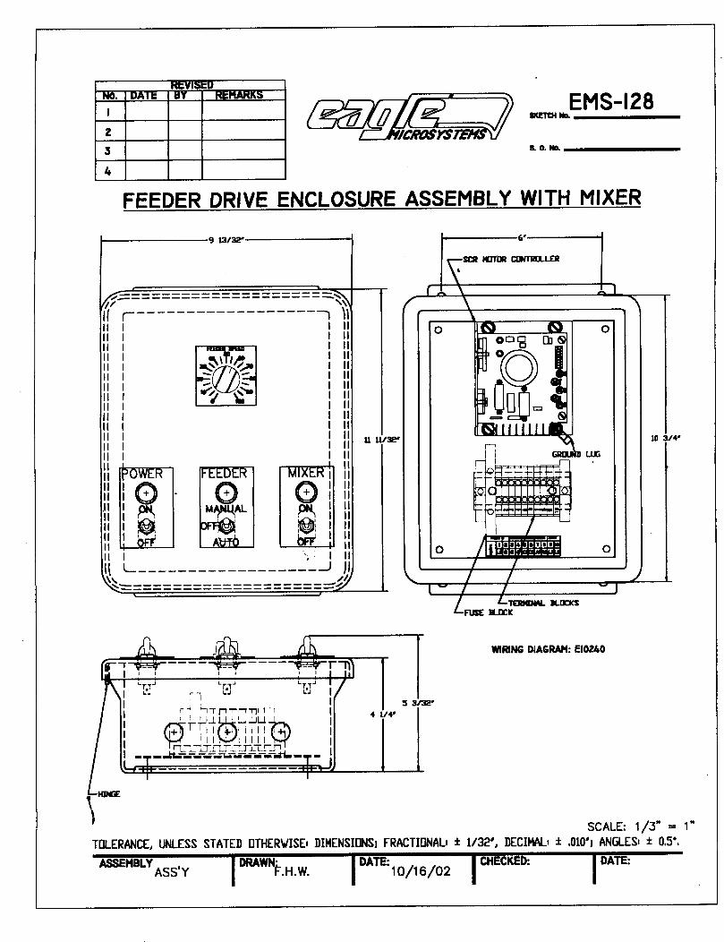
FEEDER CONTROL MODULE (TYP) EMS-128
SERIES VF-100 SCREW FEEDER
3
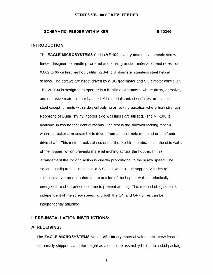
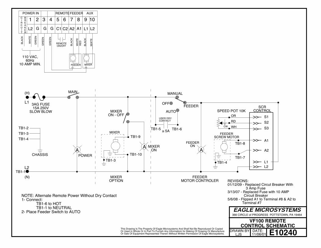
SCHEMATIC, FEEDER WITH MIXER E-10240
INTRODUCTION: The EAGLE MICROSYSTEMS Series VF-100 is a dry material volumetric screw feeder designed to handle powdered and small granular material at feed rates from 0.002 to 65 cu feet per hour, utilizing 3/4 to 3” diameter stainless steel helical screws. The screws are direct driven by a DC gearmotor and SCR motor controller. The VF-100 is designed to operate in a hostile environment, where dusty, abrasive, and corrosive materials are handled. All material contact surfaces are stainless steel except for units with side wall pulsing or rocking agitation where high strength Neoprene or Buna N/Vinyl hopper side wall liners are utilized. The VF-100 is available in two hopper configurations. The first is the sidewall rocking motion where, a rocker arm assembly is driven from an eccentric mounted on the feeder drive shaft. This motion rocks plates under the flexible membranes in the side walls of the hopper, which prevents material arching across the hopper. In this arrangement the rocking action is directly proportional to the screw speed. The second configuration utilizes solid S.S. side walls in the hopper. An electro- mechanical vibrator attached to the outside of the hopper wall is periodically energized for short periods of time to prevent arching. This method of agitation is independent of the screw speed, and both the ON and OFF times can be independently adjusted. I. PRE-INSTALLATION INSTRUCTIONS: A. RECEIVING: The EAGLE MICROSYSTEMS Series VF-100 dry material volumetric screw feeder is normally shipped via motor freight as a complete assembly bolted to a skid package.
SERIES VF-100 SCREW FEEDER
4
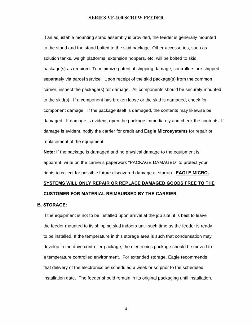
If an adjustable mounting stand assembly is provided, the feeder is generally mounted to the stand and the stand bolted to the skid package. Other accessories, such as solution tanks, weigh platforms, extension hoppers, etc. will be bolted to skid package(s) as required. To minimize potential shipping damage, controllers are shipped separately via parcel service. Upon receipt of the skid package(s) from the common carrier, inspect the package(s) for damage. All components should be securely mounted to the skid(s). If a component has broken loose or the skid is damaged, check for component damage. If the package itself is damaged, the contents may likewise be damaged. If damage is evident, open the package immediately and check the contents. If damage is evident, notify the carrier for credit and Eagle Microsystems for repair or replacement of the equipment. Note: If the package is damaged and no physical damage to the equipment is apparent, write on the carrier’s paperwork “PACKAGE DAMAGED” to protect your rights to collect for possible future discovered damage at startup. EAGLE MICRO- SYSTEMS WILL ONLY REPAIR OR REPLACE DAMAGED GOODS FREE TO THE CUSTOMER FOR MATERIAL REIMBURSED BY THE CARRIER. B. STORAGE: If the equipment is not to be installed upon arrival at the job site, it is best to leave the feeder mounted to its shipping skid indoors until such time as the feeder is ready to be installed. If the temperature in this storage area is such that condensation may develop in the drive controller package, the electronics package should be moved to a temperature controlled environment. For extended storage, Eagle recommends that delivery of the electronics be scheduled a week or so prior to the scheduled installation date. The feeder should remain in its original packaging until installation.
SERIES VF-100 SCREW FEEDER
5
C. LOCATION: The feeder should be installed in an area which is clean and dry and without excessive drafts that will blow fine material into the air. This will prevent a dusting problem that would be detrimental to both personnel and other equipment in the area. Damp locations can cause some materials to absorb moisture. This can affect the handling properties of the material causing difficulties in feeding the material. D. UNPACKING: Remove all strapping and packing material from the feeder assembly. If furnished
with a scale, remove the shipping spacers from beneath the scale plate and lower the
scale so that the leveling feet are resting on the feeder stand.
II. INSTALLATION INSTRUCTIONS:
Move the feeder assembly to the desired location and orientation. Level the feeder stand and bolt it down. The stand height is pre-adjusted at the factory. However, should height adjustment be necessary it can be accomplished in the field with ordinary hand tools. Once the feeder assembly is in place, remove the four (4) 1-inch long x ¼-20 hex bolts from the leveling feet, and install the four (4) 5/8-inch long x ¼-20 hex bolts into the shock mount. Adjust the leveling feet of the scale from the under side of the feeder stand platform. DO NOT OVER-TIGHTEN! These screws are only to keep the scale from moving on the stand. If tightened completely they will apply load to the load cells, and this will result in inaccurate scale measurements.
On installations where the customer has chosen not to purchase a mounting stand from Eagle Microsystems, the customer must provide a mounting stand. The stand must be rigid, flat and level. The stand should be large enough to support the feeder
SERIES VF-100 SCREW FEEDER
6
base and have mounting holes drilled to match the bolt pattern of the feeder. If a weigh plate is provided, its platform must be located in the correct location and at the correct height and be level. Other accessories such as a solution tank must be properly located in reference to the feeder, while accessories such as an extension hopper only have to be bolted into position atop the feeder. On some convenient structure close to the feeder locate and drill holes for mounting the motor drive controller. This location should be within a 20’ cable run of the feeder. If the controller must be located at longer distance from the feeder a junction box and cable extension box will have to be provided (by others). Wire the drive controller in accordance with the National Electric, Code, State and Local regulations. See wiring diagram provided with the feeder for basic feeder to controller connections. III. STARTUP: A. CHECK SCREW ROTATION: Once the wiring is complete and before material is added to the feeder hopper, check the rotation of the drive screw to make sure the screw is rotating in the correct direction. Start the feeder and look into the feeder hopper to observe the screw flight. If the flight appears to be advancing toward the discharge spout, the screw is rotating in the correct direction. If you are not sure, drop a small amount of material (enough to cover the flight) in the center of the feeder hopper and observe which way the flight draws the material. If the material moves toward the discharge spout, all is well. If the material moves toward the drive end of the screw, the flight is rotating backward. Rotating backward will unscrew the flight assembly from the drive shaft. Stop the motor, remove AC power from the SCR controller and reverse the two armature wires connected to the SCR terminals. If the wiring reversal is required, check that the screw is fully threaded into the drive shaft, re-apply power to
SERIES VF-100 SCREW FEEDER
7
the SCR, start the motor and check the rotation again. Once the rotation has been proven to be correct and the screw is fully secured to the drive shaft, you are ready to fill the hopper with material. B. DETERMINE ACTUAL FEED RATES: Actual feed rates vary in accordance with material density, material flow
characteristics and ambient environmental influences. For accurate results it is
important that you determine the actual feed rates you can expect at different settings
of the speed potentiometer and, in the case of a feeder equipped with the remote
analog speed control option, different control input levels. This is best accomplished
with an accurate portable scale and a timing device. Recording the weight of material
fed over a reasonable period of time at various settings will allow you to develop a
very accurate feed rate table for your particular conditions.
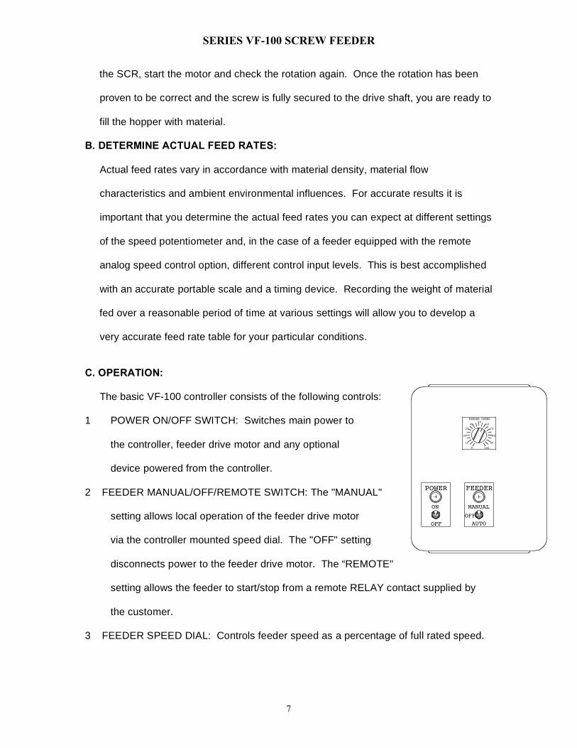
C. OPERATION: The basic VF-100 controller consists of the following controls:
1 POWER ON/OFF SWITCH: Switches main power to
the controller, feeder drive motor and any optional
device powered from the controller.
2 FEEDER MANUAL/OFF/REMOTE SWITCH: The "MANUAL"
setting allows local operation of the feeder drive motor
via the controller mounted speed dial. The "OFF" setting
disconnects power to the feeder drive motor. The “REMOTE"
setting allows the feeder to start/stop from a remote RELAY contact supplied by
the customer.
3 FEEDER SPEED DIAL: Controls feeder speed as a percentage of full rated speed.
POWER
ON
OFF
6040
FEEDER
AUTO
MANUAL
OFF
0
20
30
10
100
70
90
80
50FEEDER SPEED
SERIES VF-100 SCREW FEEDER
8
Other auxiliary switches and controls may be provided for optional equipment such as
solution tank mixers and hopper vibrator systems. When necessary, the operation of
these optional devices is covered in an addendum to this manual.
IV. MAINTENANCE: Drive: All bearings and critical drive components are sealed and require no periodic
lubrication. The drive hub assembly, located on the drive side of the feeder hopper,
houses the sealed bearings that support the screw flight and the seal that
prevents the material from migrating from the inside of the hopper to the bearings.
The seal packing will wear over time and should be monitored and replaced when
worn out to prevent damage to the bearings. Periodically check for packing failure by
removing the drive guard and observing the “weep hole” on the underside of the hub
assembly. If chemical is observed in the hole or piled beneath it, replace the
packing. During routine maintenance shutdowns, empty the hopper and observe the
packing. If there is less than l/8” of white packing material visible, replace the
packing. Unscrew the feed screw and the packing flange. The spring loaded seal
housing should come out of the hub. Remove the teflon packing material, replace it
and reassemble with a new seal O-ring in the hub. If the material has penetrated the
inside of the hub assembly and bearings, wash them out and then check the
bearings for run out and play. If in doubt, replace the bearings, or if the bearings
seem OK, re-assemble the drive hub.
SERIES VF-100 SCREW FEEDER
9
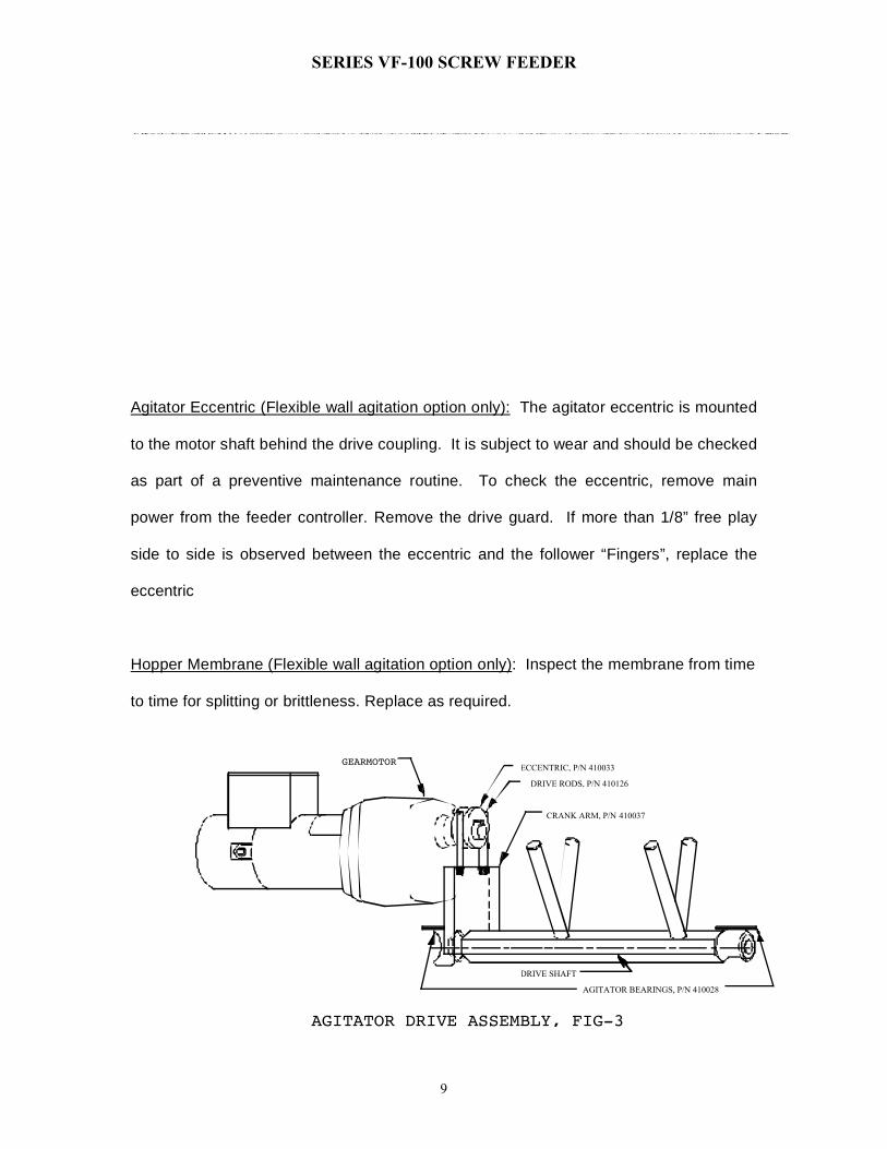
Agitator Eccentric (Flexible wall agitation option only): The agitator eccentric is mounted
to the motor shaft behind the drive coupling. It is subject to wear and should be checked
as part of a preventive maintenance routine. To check the eccentric, remove main
power from the feeder controller. Remove the drive guard. If more than 1/8” free play
side to side is observed between the eccentric and the follower “Fingers”, replace the
eccentric
Hopper Membrane (Flexible wall agitation option only): Inspect the membrane from time
to time for splitting or brittleness. Replace as required.
GEARMOTOR
AGITATOR DRIVE ASSEMBLY, FIG-3
ECCENTRIC, P/N 410033
DRIVE RODS, P/N 410126
AGITATOR BEARINGS, P/N 410028
DRIVE SHAFT
CRANK ARM, P/N 410037
SERIES VF-100 SCREW FEEDER
10
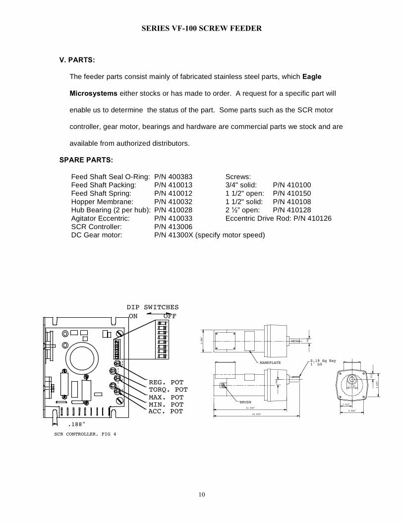
V. PARTS: The feeder parts consist mainly of fabricated stainless steel parts, which Eagle Microsystems either stocks or has made to order. A request for a specific part will enable us to determine the status of the part. Some parts such as the SCR motor controller, gear motor, bearings and hardware are commercial parts we stock and are available from authorized distributors. SPARE PARTS: Feed Shaft Seal O-Ring: P/N 400383 Screws: Feed Shaft Packing: P/N 410013 3/4" solid: P/N 410100 Feed Shaft Spring: P/N 410012 1 1/2" open: P/N 410150 Hopper Membrane: P/N 410032 1 1/2" solid: P/N 410108 Hub Bearing (2 per hub): P/N 410028 2 ½” open: P/N 410128 Agitator Eccentric: P/N 410033 Eccentric Drive Rod: P/N 410126 SCR Controller: P/N 413006 DC Gear motor: P/N 41300X (specify motor speed)
.188"
ON OFF
ACC. POTMIN. POTMAX. POTTORQ. POTREG. POT
1A1 L2A2 1 23 1 2
A
AC
M
I
RE
TO
8
7
6
5
4
3
2
1
DIP SWITCHES
SCR CONTROLLER, FIG 4
BRUSH
NAMEPLATE0.19 Sq Key1' LG
3.
38
0"
.7
50
"
.9
12
"
1.630"
1.812"
3.625"
3.
62
5"
.9
00
"
11.310"
13.310"
MAIN
E10240VF100 REMOTE
CONTROL SCHEMATICDRAWN BY:
LJSDATE:
EAGLE MICROSYSTEMS366 CIRCLE of PROGRESS POTTSTOWN, PA 19464
This Drawing Is The Property Of Eagle Microsystems And Shall Not Be Reproduced Or Copied Or Used In Whole Or In Part To Furnish Any Informatiom for Making Of Drawing Or Manufacture Or Sale Of Equipment Represented Therein Without Written Permission Of Eagle Microsystems.
BLAC
K
WHI
TE
GRE
EN
GRE
EN
BLAC
K
RED
FEEDER MIXER
110 VAC, 60Hz
10 AMP MIN.
WHI
TE
1 2 3 4 5 6 7 8 9 10
L2 G G G C1 C2 A2 A1 L1 L2
POWER IN REMOTE FEEDER AUX
BLAC
K
WHI
TE
GRE
ENREMOTE ON/OFF
C I R C U I T
MIXER ON
TB1-9
TB1-10
MIXER
MIXER ON - OFF
TB1-3
A
ORRDWH
TB1-7
TB1-8
TB1-1
FEEDER SCREW MOTOR
SPEED POT 10K
L1
L2
S1
S3
A1
A2
L2
>>–>>–
>>–
>>–
>>–>>–
S2>>–
L1POWER
CW
(H)
(N)
FEEDER ON
MANUAL
OFF
TB1-5 TB1-6
USER DRY CONTACT
≥ 5A
A
AUTO
TB1-4
SCR CONTROL
CHASSIS
TB1-2TB1-3TB1-4
A
FEEDER
MIXER OPTION
FEEDER MOTOR CONTROLER
11/06/01
B R E A K E R
REVISIONS: 01/12/09 - Replaced Circut Breaker With 3 Amp Fuse 3/13/07 - Replaced Fuse with 10 AMP Circuit Breaker 5/6/08 - Flipped A1 to Terminal #8 & A2 to
Terminal #7
3AG FUSE 15A 250V
SLOW BLOW
NOTE: Alternate Remote Power Without Dry Contact 1- Connect:
TB1-6 to HOT TB1-1 to NEUTRAL
2- Place Feeder Switch to AUTO