Embed Size (px)
Citation preview
Vesta-Series-DS v1.0 Page 1 of 18
Rigado Inc.
3950 Fairview Industrial Dr.
Salem, Oregon 97302
866-6-RIGADO [email protected]
www.rigado.com/products/iot-gateways
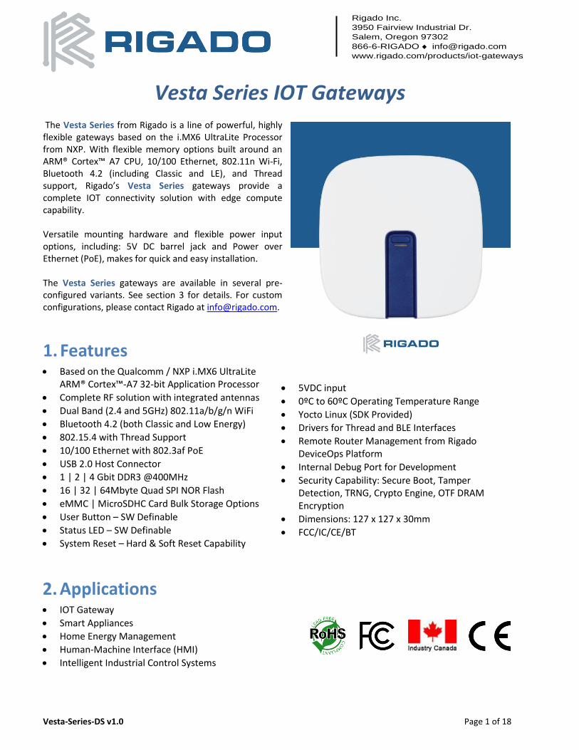
Vesta Series IOT Gateways The Vesta Series from Rigado is a line of powerful, highly flexible gateways based on the i.MX6 UltraLite Processor from NXP. With flexible memory options built around an ARM® Cortex™ A7 CPU, 10/100 Ethernet, 802.11n Wi-Fi, Bluetooth 4.2 (including Classic and LE), and Thread support, Rigado’s Vesta Series gateways provide a complete IOT connectivity solution with edge compute capability. Versatile mounting hardware and flexible power input options, including: 5V DC barrel jack and Power over Ethernet (PoE), makes for quick and easy installation. The Vesta Series gateways are available in several pre-configured variants. See section 3 for details. For custom configurations, please contact Rigado at [email protected].
1. Features • Based on the Qualcomm / NXP i.MX6 UltraLite
ARM® Cortex™-A7 32-bit Application Processor
• Complete RF solution with integrated antennas
• Dual Band (2.4 and 5GHz) 802.11a/b/g/n WiFi
• Bluetooth 4.2 (both Classic and Low Energy)
• 802.15.4 with Thread Support
• 10/100 Ethernet with 802.3af PoE
• USB 2.0 Host Connector
• 1 | 2 | 4 Gbit DDR3 @400MHz
• 16 | 32 | 64Mbyte Quad SPI NOR Flash
• eMMC | MicroSDHC Card Bulk Storage Options
• User Button – SW Definable
• Status LED – SW Definable
• System Reset – Hard & Soft Reset Capability
• 5VDC input
• 0ºC to 60ºC Operating Temperature Range
• Yocto Linux (SDK Provided)
• Drivers for Thread and BLE Interfaces
• Remote Router Management from Rigado DeviceOps Platform
• Internal Debug Port for Development
• Security Capability: Secure Boot, Tamper Detection, TRNG, Crypto Engine, OTF DRAM Encryption
• Dimensions: 127 x 127 x 30mm
• FCC/IC/CE/BT
2. Applications • IOT Gateway
• Smart Appliances
• Home Energy Management
• Human-Machine Interface (HMI)
• Intelligent Industrial Control Systems
Vesta Series Gateway Datasheet
August 14, 2017
Vesta-Series-DS-V1.0 Page 2 of 18
3. Ordering Information Email [email protected] for quotes and custom orders, or visit www.rigado.com/products/iot-gateways
Standard Model Part #
DRAM NOR Flash
Bulk Storage
Ethernet WiFi Low
Power Wireless
PoE / USB
Accessories
Vesta-100B VG3-1E4-B0C0-US
128MB None 4GB eMMC
Yes No BMD-300 BLE 4.2
USB N/A
Vesta-200B VG3-2E4-WIB0C0-USA
256MB None 4GB eMMC
Yes Yes BMD-300 BLE 4.2
USB Wall Mount AC Adapter
Vesta-200R VG3-2E4-WITAC0-USA
256MB None 4GB eMMC
Yes Yes R41Z BLE 4.2 + 802.15.4
USB Wall Mount AC Adapter
Vesta-300B VGS-23E4-WIB0C0-ASA
256MB 32MB 4GB eMMC
Yes Yes BMD-300 BLE 4.2
PoE + USB
Wall Mount AC Adapter
Vesta-300R VGS-23E4-WITAC0-ASA
256MB 32MB 4GB eMMC
Yes Yes R41Z BLE 4.2 + 802.15.4
PoE + USB
Wall Mount AC Adapter
Table 1 – Ordering Part Numbers
3.1 In the Box
IOT Gateway • Vesta Series Gateway (see standard models above in section 3)
Accessories • 5V, 2A (10W) AC/DC Wall Adapter (Part#: 820-00029)
• Wall/Ceiling Mount Kit
o Vesta mounting backer plate (Part#: 820-00022)
o Vesta mounting hardware (Part#: 820-00027)
▪ Drywall Anchor, #6-#8 Screw, 1-1/4" Length
▪ M3 x 50 mm Length, Pan Head, Phillips #1, Machine Screw
▪ Screw, Pan Head Phillips Sheet Metal #6/18x1.25"
3.2 Hardware Revision/Errata Please visit developer.rigado.com for release notes and errata.
Vesta Series Datasheet IOT Gateway
14 August 2017
Vesta-Series-DS-V1.0 Page 3 of 18
Table of Contents 1. FEATURES ............................................................................................................................................................................... 1 2. APPLICATIONS ........................................................................................................................................................................ 1 3. ORDERING INFORMATION...................................................................................................................................................... 2
3.1 IN THE BOX ....................................................................................................................................................................................... 2 3.2 HARDWARE REVISION/ERRATA ............................................................................................................................................................. 2
4. SPECIFICATIONS ..................................................................................................................................................................... 4 5. HARDWARE ............................................................................................................................................................................ 5
5.1 POWER ............................................................................................................................................................................................ 5 5.1.1 Barrel Jack ................................................................................................................................................................................... 5 5.1.2 Power over Ethernet................................................................................................................................................................... 5
5.2 ETHERNET ........................................................................................................................................................................................ 5 5.3 USB ............................................................................................................................................................................................... 5 5.4 RESET .............................................................................................................................................................................................. 5 5.5 USER BUTTON ................................................................................................................................................................................... 6 5.6 MULTI-COLOR LED ............................................................................................................................................................................ 6 5.7 CABLE COVER .................................................................................................................................................................................... 6
6. ELECTRICAL SPECIFICATIONS .................................................................................................................................................. 7 6.1 ABSOLUTE MAXIMUM RATINGS............................................................................................................................................................. 7 6.2 OPERATING CONDITIONS ..................................................................................................................................................................... 7 6.3 USB CONNECTOR POWER .................................................................................................................................................................... 7 6.4 POWER CONSUMPTION ....................................................................................................................................................................... 7
7. MODULE CONNECTIVITY ........................................................................................................................................................ 8 8. MECHANICAL DATA .............................................................................................................................................................. 11
8.1 VESTA DIMENSIONS .......................................................................................................................................................................... 11 9. CUSTOM DEVELOPMENT ...................................................................................................................................................... 12 10. BLUETOOTH QUALIFICATION ................................................................................................................................................ 13 11. REGULATORY STATEMENTS .................................................................................................................................................. 13
11.1 FCC STATEMENT: ............................................................................................................................................................................ 13 11.2 IC STATEMENT: ............................................................................................................................................................................... 13 11.3 CE REGULATORY .............................................................................................................................................................................. 14 11.4 UNIT LABELING ................................................................................................................................................................................ 15 11.1 BOX LABELING ................................................................................................................................................................................. 16
12. WARRANTY .......................................................................................................................................................................... 17 13. CAUTIONS ............................................................................................................................................................................ 17 14. LIFE SUPPORT POLICY ........................................................................................................................................................... 17 15. DOCUMENT HISTORY ........................................................................................................................................................... 18 16. RELATED DOCUMENTS ......................................................................................................................................................... 18
Vesta Series Datasheet IOT Gateway
14 August 2017
Vesta-Series-DS-V1.0 Page 4 of 18
4. Specifications Processor
i.MX6 UltraLite (G3) 528MHz ARM® Cortex™-A7
Memory
Memory (Volatile) DDR3L SDRAM @ 400MHz, x16; 128MB (1Gbit) | 256MB (2Gbit)
Memory (Program Flash) QSPI NOR FLASH; 16MB (128Mbit) | 32MB (256Mbit)
Memory (Bulk Storage) eMMC (4GB) | MicroSDHC (8GB)
WiFi (802.11a/b/g/n)
Frequency 2.412GHz - 2.484GHz; 5.180GHz – 5.925GHz
Modulations DSSS, FHSS | OFDM
Transmit Power 19 to 12.5dBm for 2.4GHz band, 17 to 10.5dBm for 5GHz band, see QCA6234 datasheet
Receiver Sensitivity -98 to -72dBm for 2.4GHz band, -92 to -68dBm for 5GHz band, depending on modulation
Antenna Integrated 2.4GHz and Integrated 5GHz
Bluetooth BMD-300 Module R41Z Module
Bluetooth Version 4.2 (Bluetooth Low Energy) 4.2 (Bluetooth Low Energy)
LE Connections Up to 20 connections Two connections
Frequency 2.360 to 2.5 GHz 2.360GHz to 2.483GHz
Modulations GFSK at 1Mbps, 2Mbps data rates GFSK at 1Mbps
Transmit Power 4dBm 3.5dBm
Receiver Sensitivity -96dBm -95dBm
Thread (802.15.4) R41Z configuration (only)
Frequency 2.360GHz to 2.483GHz
Modulations OQPSK @ 250kbps
Transmit Power 3.5dBm
Receiver Sensitivity -100dBm
Ethernet
10/100 Base-T RJ-45 connector with PoE Support
USB
USB 2.0, A-type Host connector
Dimensions
Vesta Enclosure Length Width Height
127 mm 127 mm 30 mm
Hardware
Power supply 4.5 to 5.5VDC (3A max for LTE, 2A otherwise) via Barrel Jack (5.5mm x 2.1mm)
36-57V (IEEE 802.3af) via Ethernet connector (RJ-45). PoE is optional.
Temperature Range 0 to +60°C
Certifications
FCC / IC / CE / BT
Table 2 –Specifications
Vesta Series Datasheet IOT Gateway
14 August 2017
Vesta-Series-DS-V1.0 Page 5 of 18
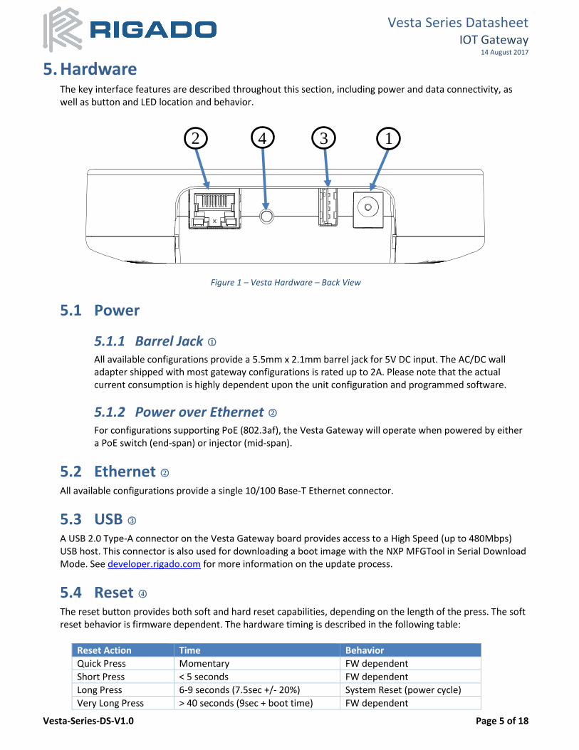
5. Hardware The key interface features are described throughout this section, including power and data connectivity, as well as button and LED location and behavior.
Figure 1 – Vesta Hardware – Back View
5.1 Power
5.1.1 Barrel Jack ○1 All available configurations provide a 5.5mm x 2.1mm barrel jack for 5V DC input. The AC/DC wall adapter shipped with most gateway configurations is rated up to 2A. Please note that the actual current consumption is highly dependent upon the unit configuration and programmed software.
5.1.2 Power over Ethernet ○2 For configurations supporting PoE (802.3af), the Vesta Gateway will operate when powered by either a PoE switch (end-span) or injector (mid-span).
5.2 Ethernet ○2 All available configurations provide a single 10/100 Base-T Ethernet connector.
5.3 USB ○3 A USB 2.0 Type-A connector on the Vesta Gateway board provides access to a High Speed (up to 480Mbps) USB host. This connector is also used for downloading a boot image with the NXP MFGTool in Serial Download Mode. See developer.rigado.com for more information on the update process.
5.4 Reset ○4 The reset button provides both soft and hard reset capabilities, depending on the length of the press. The soft reset behavior is firmware dependent. The hardware timing is described in the following table:
Reset Action Time Behavior
Quick Press Momentary FW dependent
Short Press < 5 seconds FW dependent
Long Press 6-9 seconds (7.5sec +/- 20%) System Reset (power cycle)
Very Long Press > 40 seconds (9sec + boot time) FW dependent
2 4 3 1
Vesta Series Datasheet IOT Gateway
14 August 2017
Vesta-Series-DS-V1.0 Page 6 of 18
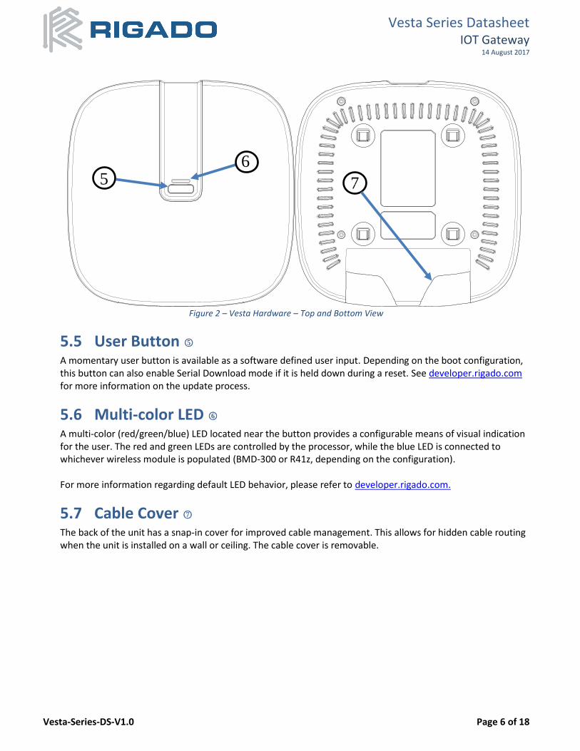
Figure 2 – Vesta Hardware – Top and Bottom View
5.5 User Button ○5 A momentary user button is available as a software defined user input. Depending on the boot configuration, this button can also enable Serial Download mode if it is held down during a reset. See developer.rigado.com for more information on the update process.
5.6 Multi-color LED ○6 A multi-color (red/green/blue) LED located near the button provides a configurable means of visual indication for the user. The red and green LEDs are controlled by the processor, while the blue LED is connected to whichever wireless module is populated (BMD-300 or R41z, depending on the configuration). For more information regarding default LED behavior, please refer to developer.rigado.com.
5.7 Cable Cover ○7 The back of the unit has a snap-in cover for improved cable management. This allows for hidden cable routing when the unit is installed on a wall or ceiling. The cable cover is removable.
5
6
7 v
Vesta Series Datasheet IOT Gateway
14 August 2017
Vesta-Series-DS-V1.0 Page 7 of 18
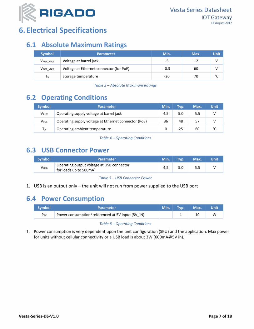
6. Electrical Specifications
6.1 Absolute Maximum Ratings Symbol Parameter Min. Max. Unit
VAUX_MAX Voltage at barrel jack -5 12 V
VPOE_MAX Voltage at Ethernet connector (for PoE) -0.3 60 V
TS Storage temperature -20 70 °C
Table 3 – Absolute Maximum Ratings
6.2 Operating Conditions Symbol Parameter Min. Typ. Max. Unit
VAUX Operating supply voltage at barrel jack 4.5 5.0 5.5 V
VPOE Operating supply voltage at Ethernet connector (PoE) 36 48 57 V
TA Operating ambient temperature 0 25 60 °C
Table 4 – Operating Conditions
6.3 USB Connector Power Symbol Parameter Min. Typ. Max. Unit
VUSB Operating output voltage at USB connector for loads up to 500mA1
4.5 5.0 5.5 V
Table 5 – USB Connector Power
1. USB is an output only – the unit will not run from power supplied to the USB port
6.4 Power Consumption Symbol Parameter Min. Typ. Max. Unit
P5V Power consumption1 referenced at 5V input (5V_IN) 1 10 W
Table 6 – Operating Conditions
1. Power consumption is very dependent upon the unit configuration (SKU) and the application. Max power for units without cellular connectivity or a USB load is about 3W (600mA@5V in).
Vesta Series Gateway Datasheet
August 14, 2017
Vesta-Series-DS-V1.0 Page 8 of 18
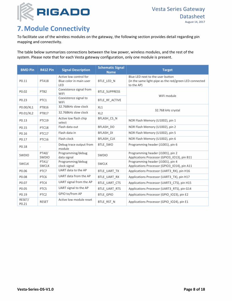
7. Module Connectivity To facilitate use of the wireless modules on the gateway, the following section provides detail regarding pin mapping and connectivity. The table below summarizes connections between the low power, wireless modules, and the rest of the system. Please note that for each Vesta gateway configuration, only one module is present.
BMD Pin R41Z Pin Signal Description Schematic Signal
Name Target
P0.11 PTA18 Active low control for Blue color in main user LED
BTLE_LED_N Blue LED next to the user button (in the same light-pipe as the red/green LED connected to the AP)
P0.02 PTB2 Coexistence signal from WiFi
BTLE_SUPPRESS
WiFi module P0.23 PTC1
Coexistence signal to WiFi
BTLE_RF_ACTIVE
P0.00/XL1 PTB16 32.768kHz slow clock XL1 32.768 kHz crystal
P0.01/XL2 PTB17 32.768kHz slow clock XL2
P0.13 PTC19 Active low flash chip select
BFLASH_CS_N NOR Flash Memory (U1002), pin 1
P0.15 PTC18 Flash data out BFLASH_DO NOR Flash Memory (U1002), pin 2
P0.16 PTC17 Flash data in BFLASH_DI NOR Flash Memory (U1002), pin 5
P0.17 PTC16 Flash clock BFLASH_CLK NOR Flash Memory (U1002), pin 6
P0.18 - Debug trace output from module
BTLE_SWO Programming header (J1001), pin 6
SWDIO PTA0/ SWDIO
Programming/debug data signal
SWDIO Programming header (J1001), pin 2 Applications Processor (GPIO3_IO13), pin B11
SWCLK PTA1/ SWCLK
Programming/debug clock signal
SWCLK Programming header (J1001), pin 4 Applications Processor (GPIO3_IO14), pin A11
P0.06 PTC7 UART data to the AP BTLE_UART_TX Applications Processor (UART3_RX), pin H16
P0.08 PTC6 UART data from the AP BTLE_UART_RX Applications Processor (UART3_TX), pin H17
P0.07 PTC4 UART signal from the AP BTLE_UART_CTS Applications Processor (UART3_CTS), pin H15
P0.05 PTC5 UART signal to the AP BTLE_UART_RTS Applications Processor (UART3_RTS), pin G14
P0.19 PTC2 GPIO to/from AP BTLE_GPIO Applications Processor (GPIO_IO23), pin E2
RESET/ P0.21
RESET Active low module reset
BTLE_RST_N Applications Processor (GPIO_IO24), pin E1
Vesta Series Gateway Datasheet
August 14, 2017
Vesta-Series-DS-V1.0 Page 9 of 18
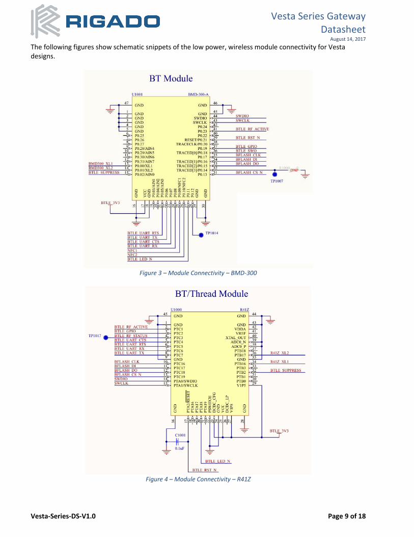
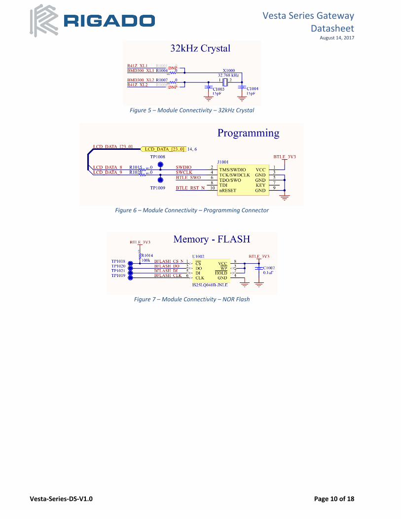
The following figures show schematic snippets of the low power, wireless module connectivity for Vesta designs.
Figure 3 – Module Connectivity – BMD-300
Figure 4 – Module Connectivity – R41Z
Vesta Series Gateway Datasheet
August 14, 2017
Vesta-Series-DS-V1.0 Page 10 of 18
Figure 5 – Module Connectivity – 32kHz Crystal
Figure 6 – Module Connectivity – Programming Connector
Figure 7 – Module Connectivity – NOR Flash
Vesta Series Gateway Datasheet
August 14, 2017
Vesta-Series-DS-V1.0 Page 11 of 18
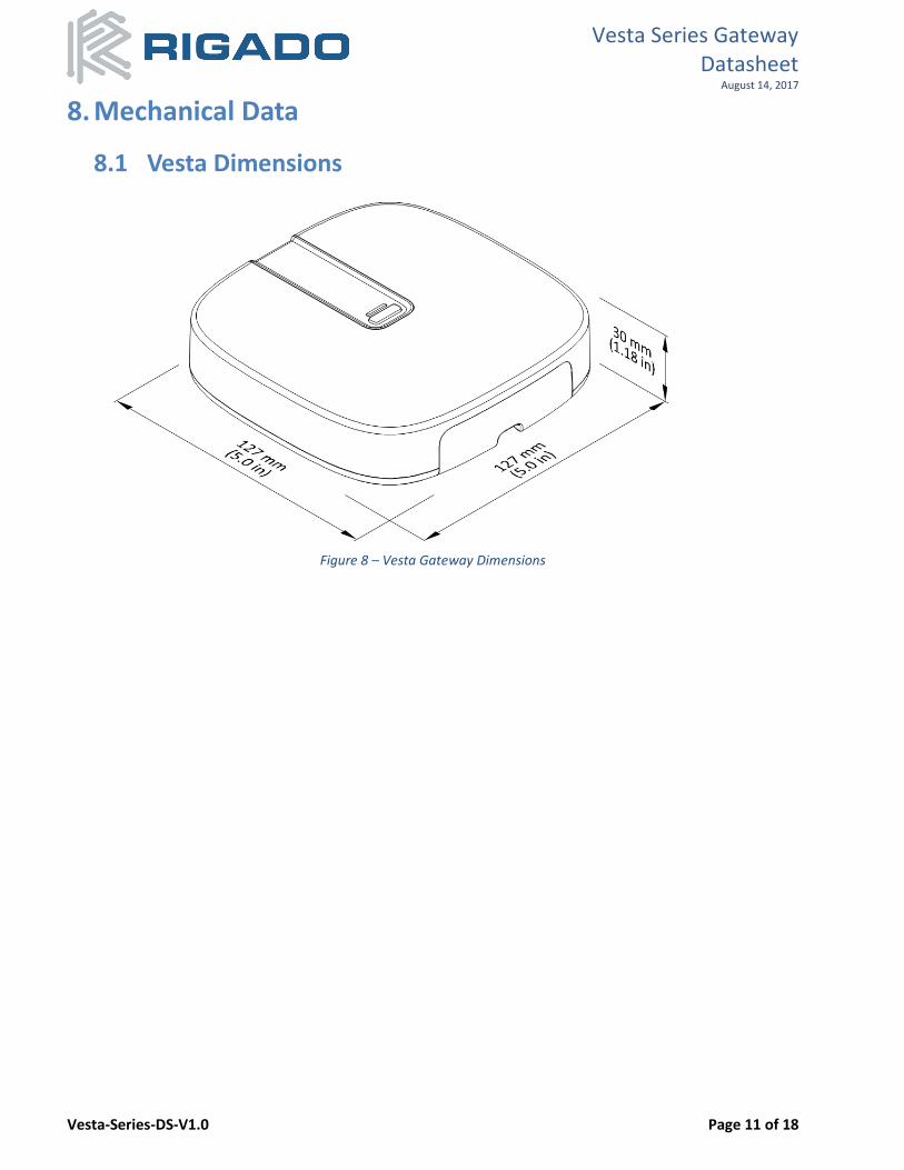
8. Mechanical Data
8.1 Vesta Dimensions
Figure 8 – Vesta Gateway Dimensions
Vesta Series Gateway Datasheet
August 14, 2017
Vesta-Series-DS-V1.0 Page 12 of 18
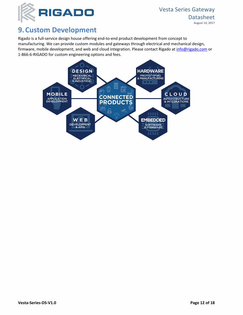
9. Custom Development Rigado is a full-service design house offering end-to-end product development from concept to manufacturing. We can provide custom modules and gateways through electrical and mechanical design, firmware, mobile development, and web and cloud integration. Please contact Rigado at [email protected] or 1-866-6-RIGADO for custom engineering options and fees.
Vesta Series Gateway Datasheet
August 14, 2017
Vesta-Series-DS-V1.0 Page 13 of 18
10. Bluetooth Qualification The Bluetooth modules are qualified as a Bluetooth Component (tested) for RF-PHY. This allows customers to use different Bluetooth stacks that have been qualified by Nordic or NXP without the need to complete additional RF-PHY testing. To achieve Bluetooth End Product qualification, the Rigado RF-PHY QDID can be combined with Nordic or NXP QDIDs used when filing on the Bluetooth SIG website. The only testing required is for the Bluetooth profiles supported by the Gateway’s applications. Applications with only custom profiles do not require any additional testing.
• BMD-300: RF-PHY v4.2 Component(Tested) Declaration ID D030629 / QDID 81876
• R41Z-T RF-PHY v4.2 Component(Tested): Declaration ID D035037 / QDID 95459
11. Regulatory Statements
11.1 FCC Statement: This device has been tested and found to comply with part 15 of the FCC rules. These limits are designed to provide reasonable protection against harmful interference in a residential installation. This equipment generates, uses and can radiate radio frequency energy and, if not installed and used in accordance with the instructions, may cause harmful interference to radio communications. However, there is no guarantee that interference will not occur in a particular installation. If this equipment does cause harmful interference to radio or television reception, which can be determined by turning the equipment off and on, the user is encouraged to try to correct the interference by one or more of the following measures:
• Reorient or relocate the receiving antenna.
• Increase the separation between the equipment and the receiver
• Connect the equipment into an outlet on a circuit different from that to which the receiver is connected.
• Consult the dealer or an experienced radio/TV technician for help. Operation is subjected to the following two conditions: (1) This device may no cause harmful interference, and (2) this device must accept any interference received, including interference that may cause undesired operation. Note: Modification to this product will void the user’s authority to operate this equipment. Note: Modification to this product will void the users’ authority to operate this equipment.
11.2 IC Statement: This device complies with Industry Canada license-exempt RSS standard(s). Operation is subject to the following two conditions: (1) this device may not cause interference, and (2) this device must accept any interference, including interference that may cause undesired operation of the device. Le présent appareil est conforme aux CNR d'Industrie Canada applicables aux appareils radio exempts de licence. L'exploitation est autorisée aux deux conditions suivantes : (1) l'appareil ne doit pas produire de brouillage, et (2) l'utilisateur de l'appareil doit accepter tout brouillage radioélectrique subi, même si le brouillage est susceptible d'en compromettre le fonctionnement. RF exposure warning: The equipment complies with RF exposure limits set forth for an uncontrolled environment. The antenna(s) used for this transmitter must not be co-located or operating in conjunction with any other antenna or transmitter.
Vesta Series Gateway Datasheet
August 14, 2017
Vesta-Series-DS-V1.0 Page 14 of 18
Avertissement d'exposition RF: L'équipement est conforme aux limites d'exposition aux RF établies pour un incontrôlés environnement. L'antenne (s) utilisée pour ce transmetteur ne doit pas être co-localisés ou onctionner en conjonction avec toute autre antenne ou transmetteur .
11.3 CE Regulatory The Vesta Series IoT Gateways are tested and compliant against the following standards.
• EN 60950-1: 2006 + A11: 2009 + A1: 2010 + A12: 2011*
• ETSI EN 300 328 V 2.1.1
• ETSI EN 300 440 V 2.1.1
• ETSI EN 301 489-1 V 2.1.1
• ETSI EN 301 489-3 V 2.1.1
• ETSI EN 301 489-17 V 3.1.1
• ETSI EN 301 893 V 2.1.1
• EN 55024: 2010 + A1: 2015
• EN 55032: 2015
• EN 61000-3-2: 2014
• EN 61000-3-3: 2013 Declarations of Conformity and supporting test reports are available at www.rigado.com.
Vesta Series Gateway Datasheet
August 14, 2017
Vesta-Series-DS-V1.0 Page 15 of 18
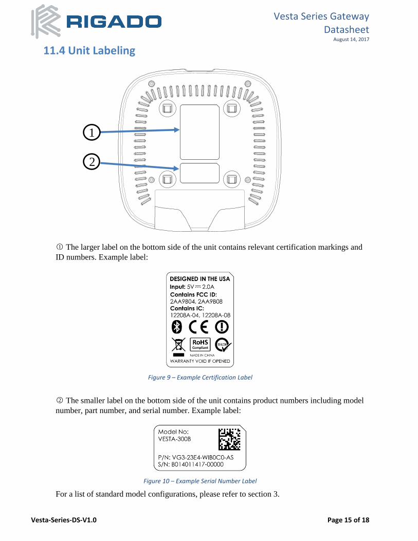
11.4 Unit Labeling
○1 The larger label on the bottom side of the unit contains relevant certification markings and
ID numbers. Example label:
Figure 9 – Example Certification Label
○2 The smaller label on the bottom side of the unit contains product numbers including model
number, part number, and serial number. Example label:
Figure 10 – Example Serial Number Label
For a list of standard model configurations, please refer to section 3.
2
1
Vesta Series Gateway Datasheet
August 14, 2017
Vesta-Series-DS-V1.0 Page 16 of 18
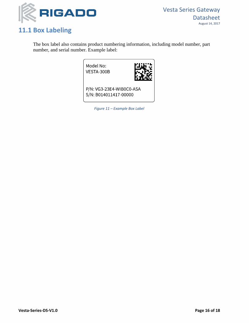
11.1 Box Labeling
The box label also contains product numbering information, including model number, part
number, and serial number. Example label:
Figure 11 – Example Box Label
Vesta Series Gateway Datasheet
August 14, 2017
Vesta-Series-DS-V1.0 Page 17 of 18
12. Warranty Rigado offers a 1-year limited warranty for all Vesta Series products. IMPORTANT NOTE: Warranty is void if the unit enclosure is opened for any reason.
13. Cautions 1) The guidelines of this document should be followed to ensure proper performance of the product. 2) This product is for use in office, business, and residential applications. 3) Supply voltage to the product should not be higher than the specified inputs or reversed. Additionally, it
should not contain noise, spikes, or AC ripple voltage. 4) Do not open the product enclosure. 5) This product should be kept away from direct heat, both during storage and after installation. 6) Do not drop or physically shock the product. 7) Do not damage the interface surfaces of the product. 8) The product should not be mechanically stressed at any time (storage, handling, installation). 9) Do not expose this product to:
• Humid or salty air conditions
• High concentrations of corrosive gasses.
• Temperatures lower than -20°C or higher than 70°C.
14. Life Support Policy This product is not designed to be used in a life support device or system, or in applications where there is potential for a failure or malfunction to, directly or indirectly, cause significant injury. By using this product in an application that poses these risks, such as described above, the customer is agreeing to indemnify Rigado for any damages that result.
Vesta Series Gateway Datasheet
August 14, 2017
Vesta-Series-DS-V1.0 Page 18 of 18
15. Document History Revision Date Changes / Notes
1.0 2017-8-11 Initial release
16. Related Documents Please refer to developer.rigado.com for additional information.
Mouser Electronics
Authorized Distributor
Click to View Pricing, Inventory, Delivery & Lifecycle Information: Rigado:
Vesta-200B VG3-23E4-WIB0C0-ASA VG3-23E4-WITAC0-ASA