Embed Size (px)
Citation preview

E U R O P E A N S O U T H E R N O B S E R V A T O R YOrganisation Européenne pour des Recherches Astronomiques dans l’Hémisphère Austral
Europäische Organisation für astronomische Forschung in der südlichen Hemisphäre
VERY LARGE TELESCOPE
Prepared.....................................................................................................Name Date Signature
Approved...................................................................................................Name Date Signature
Released .....................................................................................................Name Date Signature
Doc.No. VLT-SPE-ESO-13660-3836
Issue 2.4
Date 25/05/07
VLT PROGRAMME * TELEPHONE: +49 89 32006-0 * FAX: +49 89 320 2362
ESO New General Detector Controller
Base Software
Design Description
A.Moorwood
J.Stegmeier 25/05/07
D.Baade, G.Finger

2 NGC Base Software Design - 2.4 VLT-SPE-ESO-13660-3836

NGC Base Software Design - 2.4 VLT-SPE-ESO-13660-3836 3
Change Record
Issue/Rev. Date Section/Page affected Reason/Initiation/Document/Remarks
0.1 30/11/05 All First preparation.
1.0 27/03/06 3
4
6.3.1
9
10
Added sections for testing, logging and errorhandling. Newfigure for class structure.
Some issues for driver compilation and installa-tion.
Added dwell-time modification flag to binaryclock pattern format.
Added traceability matrix.
Updated.
2.0 10/08/06 All Revised version.
2.1 30/08/06 6.610
New section added.Updated man-pages.
2.2 03/01/07 All10
Aligned with new naming conventions.Updated man-pages.
2.3 19/02/07 6.37.310
Some addtional script instructions.Modified type definitions.Updated man-pages.
2/4 25/05/07 10 Updated man-pages

4 NGC Base Software Design - 2.4 VLT-SPE-ESO-13660-3836

NGC Base Software Design - 2.4 VLT-SPE-ESO-13660-3836 5
T A B L E O F C O N T E N T S
1 INTRODUCTION 91.1 Purpose . . . . . . . . . . . . . . . . . . . . . . . . . . . . . . . . . . . . . . . . . . . . . . . . . . . . . . . . . . . . . . . . . . . . . . . 91.2 Scope . . . . . . . . . . . . . . . . . . . . . . . . . . . . . . . . . . . . . . . . . . . . . . . . . . . . . . . . . . . . . . . . . . . . . . . . . 91.3 Applicable and Reference Documents . . . . . . . . . . . . . . . . . . . . . . . . . . . . . . . . . . . . . . . . . . . . . 91.4 Glossary. . . . . . . . . . . . . . . . . . . . . . . . . . . . . . . . . . . . . . . . . . . . . . . . . . . . . . . . . . . . . . . . . . . . . . . 91.5 Abbreviations and Acronyms . . . . . . . . . . . . . . . . . . . . . . . . . . . . . . . . . . . . . . . . . . . . . . . . . . . . 9
2 HARDWARE OVERVIEW 112.1 Detector Front End . . . . . . . . . . . . . . . . . . . . . . . . . . . . . . . . . . . . . . . . . . . . . . . . . . . . . . . . . . . . 112.2 Computing Architecture. . . . . . . . . . . . . . . . . . . . . . . . . . . . . . . . . . . . . . . . . . . . . . . . . . . . . . . . 122.3 Communication Protocol . . . . . . . . . . . . . . . . . . . . . . . . . . . . . . . . . . . . . . . . . . . . . . . . . . . . . . . 122.4 Voltage Programming. . . . . . . . . . . . . . . . . . . . . . . . . . . . . . . . . . . . . . . . . . . . . . . . . . . . . . . . . . 132.5 Sequencer Programming . . . . . . . . . . . . . . . . . . . . . . . . . . . . . . . . . . . . . . . . . . . . . . . . . . . . . . . 13
2.5.1 Clock Pattern RAM . . . . . . . . . . . . . . . . . . . . . . . . . . . . . . . . . . . . . . . . . . . . . . . . . . . . . . 132.5.2 Sequencer Program RAM. . . . . . . . . . . . . . . . . . . . . . . . . . . . . . . . . . . . . . . . . . . . . . . . . 14
2.6 Sequencer Control . . . . . . . . . . . . . . . . . . . . . . . . . . . . . . . . . . . . . . . . . . . . . . . . . . . . . . . . . . . . . 152.7 Synchronization . . . . . . . . . . . . . . . . . . . . . . . . . . . . . . . . . . . . . . . . . . . . . . . . . . . . . . . . . . . . . . . 15
3 SOFTWARE ARCHITECTURE 173.1 Hierarchy . . . . . . . . . . . . . . . . . . . . . . . . . . . . . . . . . . . . . . . . . . . . . . . . . . . . . . . . . . . . . . . . . . . . 173.2 Software Modules . . . . . . . . . . . . . . . . . . . . . . . . . . . . . . . . . . . . . . . . . . . . . . . . . . . . . . . . . . . . . 183.3 Test Software . . . . . . . . . . . . . . . . . . . . . . . . . . . . . . . . . . . . . . . . . . . . . . . . . . . . . . . . . . . . . . . . . 183.4 Class Structure . . . . . . . . . . . . . . . . . . . . . . . . . . . . . . . . . . . . . . . . . . . . . . . . . . . . . . . . . . . . . . . . 183.5 Verbose Mode and Logging . . . . . . . . . . . . . . . . . . . . . . . . . . . . . . . . . . . . . . . . . . . . . . . . . . . . . 203.6 Error Handling. . . . . . . . . . . . . . . . . . . . . . . . . . . . . . . . . . . . . . . . . . . . . . . . . . . . . . . . . . . . . . . . 20
4 DEVICE DRIVER 234.1 NGC Communication Channel . . . . . . . . . . . . . . . . . . . . . . . . . . . . . . . . . . . . . . . . . . . . . . . . . . 234.2 DMA Data Acquisition . . . . . . . . . . . . . . . . . . . . . . . . . . . . . . . . . . . . . . . . . . . . . . . . . . . . . . . . . 234.3 Commands . . . . . . . . . . . . . . . . . . . . . . . . . . . . . . . . . . . . . . . . . . . . . . . . . . . . . . . . . . . . . . . . . . . 254.4 Driver Interface Libraries . . . . . . . . . . . . . . . . . . . . . . . . . . . . . . . . . . . . . . . . . . . . . . . . . . . . . . . 27
5 NGC INTERFACE CLASS 295.1 Interface Base Class . . . . . . . . . . . . . . . . . . . . . . . . . . . . . . . . . . . . . . . . . . . . . . . . . . . . . . . . . . . . 295.2 Interface Instantiation . . . . . . . . . . . . . . . . . . . . . . . . . . . . . . . . . . . . . . . . . . . . . . . . . . . . . . . . . . 315.3 NGC Simulator Class . . . . . . . . . . . . . . . . . . . . . . . . . . . . . . . . . . . . . . . . . . . . . . . . . . . . . . . . . . 31
6 NGC SOFTWARE CLASSES 336.1 Module Base Class . . . . . . . . . . . . . . . . . . . . . . . . . . . . . . . . . . . . . . . . . . . . . . . . . . . . . . . . . . . . . 336.2 Parameter Model . . . . . . . . . . . . . . . . . . . . . . . . . . . . . . . . . . . . . . . . . . . . . . . . . . . . . . . . . . . . . . 346.3 Sequencer Module Class. . . . . . . . . . . . . . . . . . . . . . . . . . . . . . . . . . . . . . . . . . . . . . . . . . . . . . . . 35
6.3.1 Clock Pattern Setup. . . . . . . . . . . . . . . . . . . . . . . . . . . . . . . . . . . . . . . . . . . . . . . . . . . . . . 356.3.2 Sequencer Program . . . . . . . . . . . . . . . . . . . . . . . . . . . . . . . . . . . . . . . . . . . . . . . . . . . . . . 38

6 NGC Base Software Design - 2.4 VLT-SPE-ESO-13660-3836
6.3.3 Sequencer Control . . . . . . . . . . . . . . . . . . . . . . . . . . . . . . . . . . . . . . . . . . . . . . . . . . . . . . . 436.3.4 Synchronization . . . . . . . . . . . . . . . . . . . . . . . . . . . . . . . . . . . . . . . . . . . . . . . . . . . . . . . . . 43
6.4 CLDC Module Class . . . . . . . . . . . . . . . . . . . . . . . . . . . . . . . . . . . . . . . . . . . . . . . . . . . . . . . . . . . 446.5 ADC Module Class . . . . . . . . . . . . . . . . . . . . . . . . . . . . . . . . . . . . . . . . . . . . . . . . . . . . . . . . . . . . 466.6 Selftest . . . . . . . . . . . . . . . . . . . . . . . . . . . . . . . . . . . . . . . . . . . . . . . . . . . . . . . . . . . . . . . . . . . . . . . 466.7 Configuration Modules . . . . . . . . . . . . . . . . . . . . . . . . . . . . . . . . . . . . . . . . . . . . . . . . . . . . . . . . . 46
7 DATA PRE-PROCESSING 477.1 Concept . . . . . . . . . . . . . . . . . . . . . . . . . . . . . . . . . . . . . . . . . . . . . . . . . . . . . . . . . . . . . . . . . . . . . . 47
7.1.1 Parallel Computing Architecture . . . . . . . . . . . . . . . . . . . . . . . . . . . . . . . . . . . . . . . . . . 477.1.2 Priority Controlled Scheduling . . . . . . . . . . . . . . . . . . . . . . . . . . . . . . . . . . . . . . . . . . . . 487.1.3 The Threads-Model . . . . . . . . . . . . . . . . . . . . . . . . . . . . . . . . . . . . . . . . . . . . . . . . . . . . . . 50
7.2 The Acquisition Process . . . . . . . . . . . . . . . . . . . . . . . . . . . . . . . . . . . . . . . . . . . . . . . . . . . . . . . . 507.2.1 Initialization . . . . . . . . . . . . . . . . . . . . . . . . . . . . . . . . . . . . . . . . . . . . . . . . . . . . . . . . . . . . 517.2.2 Exporting Parameters . . . . . . . . . . . . . . . . . . . . . . . . . . . . . . . . . . . . . . . . . . . . . . . . . . . . 517.2.3 Frame Types . . . . . . . . . . . . . . . . . . . . . . . . . . . . . . . . . . . . . . . . . . . . . . . . . . . . . . . . . . . . 527.2.4 Acquisition Loop . . . . . . . . . . . . . . . . . . . . . . . . . . . . . . . . . . . . . . . . . . . . . . . . . . . . . . . . 537.2.5 Data Transfer . . . . . . . . . . . . . . . . . . . . . . . . . . . . . . . . . . . . . . . . . . . . . . . . . . . . . . . . . . . 547.2.6 Importing Data-Sets . . . . . . . . . . . . . . . . . . . . . . . . . . . . . . . . . . . . . . . . . . . . . . . . . . . . . 547.2.7 Pixel Sorting . . . . . . . . . . . . . . . . . . . . . . . . . . . . . . . . . . . . . . . . . . . . . . . . . . . . . . . . . . . . 557.2.8 Run-Time Flags . . . . . . . . . . . . . . . . . . . . . . . . . . . . . . . . . . . . . . . . . . . . . . . . . . . . . . . . . 567.2.9 Simulation Mode . . . . . . . . . . . . . . . . . . . . . . . . . . . . . . . . . . . . . . . . . . . . . . . . . . . . . . . . 56
7.3 Acquisition Process Interface . . . . . . . . . . . . . . . . . . . . . . . . . . . . . . . . . . . . . . . . . . . . . . . . . . . . 567.3.1 Data Interface . . . . . . . . . . . . . . . . . . . . . . . . . . . . . . . . . . . . . . . . . . . . . . . . . . . . . . . . . . . 567.3.2 Data Export. . . . . . . . . . . . . . . . . . . . . . . . . . . . . . . . . . . . . . . . . . . . . . . . . . . . . . . . . . . . . 597.3.3 The Acquisition Module Class. . . . . . . . . . . . . . . . . . . . . . . . . . . . . . . . . . . . . . . . . . . . . 59
8 MAINTENANCE SERVER 61
1 TRACEABILITY MATRIX 11.1 NGC Requirements from [AD6] . . . . . . . . . . . . . . . . . . . . . . . . . . . . . . . . . . . . . . . . . . . . . . . . . . 11.2 NGC Software Requirements from [AD7] . . . . . . . . . . . . . . . . . . . . . . . . . . . . . . . . . . . . . . . . . 101.3 Adaptive Optics Requirements for NGC from [AD20] . . . . . . . . . . . . . . . . . . . . . . . . . . . . . . 14
1 APPENDIX 11.1 ngcb2Drv - Command Definition Table . . . . . . . . . . . . . . . . . . . . . . . . . . . . . . . . . . . . . . . . . . . . 11.2 ngcbDrvCom. . . . . . . . . . . . . . . . . . . . . . . . . . . . . . . . . . . . . . . . . . . . . . . . . . . . . . . . . . . . . . . . . . . 41.3 ngcbDrvDma . . . . . . . . . . . . . . . . . . . . . . . . . . . . . . . . . . . . . . . . . . . . . . . . . . . . . . . . . . . . . . . . . . 51.4 ngcbPrio. . . . . . . . . . . . . . . . . . . . . . . . . . . . . . . . . . . . . . . . . . . . . . . . . . . . . . . . . . . . . . . . . . . . . . . 71.5 ngcbThread . . . . . . . . . . . . . . . . . . . . . . . . . . . . . . . . . . . . . . . . . . . . . . . . . . . . . . . . . . . . . . . . . . . . 71.6 ngcbSem . . . . . . . . . . . . . . . . . . . . . . . . . . . . . . . . . . . . . . . . . . . . . . . . . . . . . . . . . . . . . . . . . . . . . . 81.7 ncgbTHREAD Class. . . . . . . . . . . . . . . . . . . . . . . . . . . . . . . . . . . . . . . . . . . . . . . . . . . . . . . . . . . . 111.8 ngcbSEM Class . . . . . . . . . . . . . . . . . . . . . . . . . . . . . . . . . . . . . . . . . . . . . . . . . . . . . . . . . . . . . . . . 141.9 ngcbPARAM Class. . . . . . . . . . . . . . . . . . . . . . . . . . . . . . . . . . . . . . . . . . . . . . . . . . . . . . . . . . . . . 161.10 ngcbIFC Class . . . . . . . . . . . . . . . . . . . . . . . . . . . . . . . . . . . . . . . . . . . . . . . . . . . . . . . . . . . . . . . . . 20

NGC Base Software Design - 2.4 VLT-SPE-ESO-13660-3836 7
1.11 ngcbIFC_MSG Class . . . . . . . . . . . . . . . . . . . . . . . . . . . . . . . . . . . . . . . . . . . . . . . . . . . . . . . . . . . 241.12 ngcbSIM Class . . . . . . . . . . . . . . . . . . . . . . . . . . . . . . . . . . . . . . . . . . . . . . . . . . . . . . . . . . . . . . . . 251.13 ngcbNET Class . . . . . . . . . . . . . . . . . . . . . . . . . . . . . . . . . . . . . . . . . . . . . . . . . . . . . . . . . . . . . . . . 281.14 ngcbOBJ Class . . . . . . . . . . . . . . . . . . . . . . . . . . . . . . . . . . . . . . . . . . . . . . . . . . . . . . . . . . . . . . . . 301.15 ngcbMOD_CLASS . . . . . . . . . . . . . . . . . . . . . . . . . . . . . . . . . . . . . . . . . . . . . . . . . . . . . . . . . . . . . 321.16 ngcdcsCLDC_CLASS . . . . . . . . . . . . . . . . . . . . . . . . . . . . . . . . . . . . . . . . . . . . . . . . . . . . . . . . . . 341.17 ngcdcsSEQ_CLASS . . . . . . . . . . . . . . . . . . . . . . . . . . . . . . . . . . . . . . . . . . . . . . . . . . . . . . . . . . . . 381.18 ngcdcsADC_CLASS . . . . . . . . . . . . . . . . . . . . . . . . . . . . . . . . . . . . . . . . . . . . . . . . . . . . . . . . . . . 441.19 ngcdcsACQ_DATA_CLASS. . . . . . . . . . . . . . . . . . . . . . . . . . . . . . . . . . . . . . . . . . . . . . . . . . . . . 471.20 ngcdcsACQ_CLASS . . . . . . . . . . . . . . . . . . . . . . . . . . . . . . . . . . . . . . . . . . . . . . . . . . . . . . . . . . . 511.21 ngcdcsCTRL_CLASS . . . . . . . . . . . . . . . . . . . . . . . . . . . . . . . . . . . . . . . . . . . . . . . . . . . . . . . . . . . 57

8 NGC Base Software Design - 2.4 VLT-SPE-ESO-13660-3836

NGC Base Software Design - 2.4 VLT-SPE-ESO-13660-3836 9
1 INTRODUCTION
1.1 Purpose
The document describes the design of a common base software for the ESO New General detectorController (NGC). It addresses to the hardware developer in the lab, to the detector specialist, to allinstrument users including those of external consortia and to all software developers designing ap-plications based on NGC.
1.2 Scope
The new general detector controller will be used for both optical and infrared applications. Whilethe low level interfacing to the controller is the same in both cases, there are a lot of differences con-cerning how the controller is actually used. This especially concerns data pre-processing and expo-sure handling. The base software shall provide a transparent implementation of the NGC hardwaremodules, giving access through software functions to all features provided by the NGC and stillleaving full freedom in the applicable range of the NGC detector front end. The application specificparts are described in the design documents [RD10] (optical) and [RD11] (infrared).
The scope of this document covers all NGC software functionality, which can be used in all cases,even though this does not mean that all of this functionality finally will be used in all specific appli-cations. Especially the parallel pre-processing software (section 7) may be used where required,while for less challenging tasks a more simple approach may be adequate to avoid overkill solu-tions and to ease software maintenance.
Although not being part of the software design, there is a short overview of the NGC hardware, butonly to an extend of what is required to understand the software methods. A detailed description ofthe hardware is given in [RD15].
1.3 Applicable and Reference Documents
All applicable and reference documents are listed in the “NGC Project Documentation” document,VLT-LIS-ESO-13660-3906.
1.4 Glossary
See NGC Project Glossary [AD63].
1.5 Abbreviations and Acronyms
See NGC Project Acronyms [AD64].

10 NGC Base Software Design - 2.4 VLT-SPE-ESO-13660-3836
[AD1][AD2][AD3][AD4][AD5][AD6] VLT-SPE-ESO-13660-3207, 1.0 NGC Requirements Specification[AD7] VLT-SPE-ESO-13660-3670, 0.1 NGC Software Requirements[AD8] VLT-TRE-ESO-13660-3900, 1.1 New General Detector Controller - Technical Report[AD9][RD10] VLT-SPE-ESO-13660-3835, 2.0 NGC Control Software System - Optical Instruments - High-level Software Design Description[RD11] VLT-SPE-ESO-13660-3837 NGC Infrared Detector Control Software - Design Description[AD12][AD13][AD14][RD15] VLT-MAN-ESO-13640-1388 FIERA CCD Controller Software - User Manual[RD16] VLT-MAN-ESO-14100-1878 IRACE DCS - User Manual[RD17][RD18][RD19][AD20] VLT-SPE-ESO-16100-3729, 1.0 SPARTA Adaptive Optics - Specifications for NGC[AD21][AD22][AD23][AD24][AD25] VLT-PRO-ESO-10000-0228, 1.0 VLT Software Programming Standards[AD26] VLT-MAN-ESO-17210-0667, 1.3 VLT Software - Guidelines for the Development of VLT Application Software[AD27] VLT-SPE-ESO-17212-0001, 5.0 VLT Instrumentation Software Specification[AD28] VLT-SPE-ESO-17240-0385, 4.0 INS Common Software Specification[AD29][AD30][AD31][RD32] VLT-MAN-ESO-17210-0619 CCS - User Manual[RD33] VLT-MAN-ESO-17210-0770 Extended CCS - User Manual[RD34][RD35] VLT-MAN-ESO-17210-0771 CCS Event Tool Kit - EVH - User Manual[RD36][AD37] GEN-SPE-ESO-19400-0794, 3.0 Data Interface Control Document[AD38][RD39] VLT-MAN-ESO-17210-0690 VLT Software - Graphical User Interface - User Manual[RD40] VLT-MAN-ESO-17240-0866 Real Time Display - User Manual[RD41] VLT-MAN-ESO-17200-0908 Tools for Automated Testing - User Manual[RD42][RD43][RD44][RD45][RD46][RD47][RD48][RD49][RD50][RD51][RD52][RD53][RD54][RD55][RD56][RD57][RD58][RD59][RD60][RD61][RD62][AD63] VLT-LIS-ESO-13660-3907, 1.0 NGC Project Glossary[AD64] VLT-LIS-ESO-13660-3908, 1.0 NGC Project Acronyms[AD65] VLT-LIS-ESO-13660-3906, 1.0 NGC Project Documentation[AD66]

NGC Base Software Design - 2.4 VLT-SPE-ESO-13660-3836 11
2 HARDWARE OVERVIEW
The NGC hardware consists of a modular assembly of back-end and detector front-end modules.The back-end module is a PCI-Bus interface card connecting the local control and data acquisitioncomputer (NGC-LCU) to the front-end modules which are creating and receiving the detector sig-nals. The hardware module providing the clock timings is called sequencer. The hardware moduleproviding the needed clock voltage levels and the additional detector biases is called CLDC. Thehardware module doing the analog to digital conversion of the detector data is called ADC module.Data and control signals between back-end and front-end are on fiber-optic link(s) with transmis-sion rates of 2.5 GBit. Detailed descriptions of the hardware modules functionality are given in[AD8].
2.1 Detector Front End
The detector front-end consists of at least one main-board and an arbitrary number of additionalboards. The boards may contain only a sequencer-/CLDC-module or only an ADC-module (con-verting the detector output signals) or possibly any combination of those. The number of ADCs oneach ADC-module is also configurable. The boards are linked together in a network-like structure(see Figure 1). Current hardware only supports linear chains (i.e. header 0x5).
Each board is equipped with a temperature sensor, which can be read-out through a dedicated reg-ister. Each board also provides through register value(s) its own serial-number, a product code anda revision number.
Figure 1 NGC Hardware
Sequencer
CLDC
ADC System
hdr=0x5
hdr=0x6
hdr=0x8
hdr=0x2
Register
Sequencer
CLDC
ADC System
hdr=0x5
hdr=0x6
hdr=0x8
hdr=0x2
Register
Sequencer
CLDC
ADC System
hdr=0x5
hdr=0x6
hdr=0x8
hdr=0x2
Register
hdr=0x7hdr=0x7
hdr=0x7

12 NGC Base Software Design - 2.4 VLT-SPE-ESO-13660-3836
2.2 Computing Architecture
The NGC will be controlled remotely from an instrument workstation (IWS). The physical interfaceto the hardware (PCI-Bus back-end card) resides in a local computer (NGC-LCU), which is also usedfor the data acquisition and pre-processing. Currently the local computer is a PC running a Linuxoperating system (kernel 2.4 or higher). In case the maximum nesting depth inside the NGC modulenetwork has been reached, the system needs to be accessed through additional PCI-Bus back-endcards. This may imply the usage of more than one NGC-LCU, also in case the computing or pe-ripheral bus bandwidth of the NGC-LCU is not sufficient. So the configuration range covers a sim-ple system controlling one detector via one PCI-Bus interface card as well as large detector mosaicsdistributing their data via a huge number of channels among several computers.
Figure 2 Computing Architecture
2.3 Communication Protocol
The communication between back-end and front-end modules is based on packet transmission overserial links. A packet structure is defined to address a function (i.e. a register or memory in a front-end module) for reading or writing. The package is first sent to the back-end transmitter-FIFO andthen the transmission is activated upon raising a run-bit in the back-end control register. A packetwhich has reached its destination is acknowledged in the back-end status register as soon as the ad-dressed function has been executed. In case of a “read” operation the acknowledge is sent once therequested data is available in the back-end receiver-FIFO. This limits the size of a single read/writeoperation to the size of the transfer FIFOs.
A package consists of a number of headers in the range of [0x2 to 0x8] followed by the address towrite to or to read from, followed by a command code (write = 0x0, read = 0x8000000). In case of awrite operation a number of data words up to FIFO size can be appended. In case of a read opera-tion the command code is or’ed with the number of data words to be read.
NGC-LCU2PCI-Bus
Interfaces
1
2
NGC-Network
NGC-Network
NGC-Network
NGC-Network
IWS
DET
NGC-LCU1PCI-Bus
Interfaces
1
2
LAN

NGC Base Software Design - 2.4 VLT-SPE-ESO-13660-3836 13
Figure 3 Packet Structure
The packet follows the route through the front-end network as described by the headers until head-er 0x2 or header 0x8 is reached. Header 0x5, 0x6, 0x7 lead to the next board connected on the associ-ated link. Header 0x2 means, that a function on this board is addressed. Header 0x8 addresses theconfiguration register on this board (for resetting or link configuration). The configuration registeris write-only and does not send an acknowledge back. The header 0x8 is directly followed by theregister value (no address, no command code) and therefore it is an exception in the protocol.
2.4 Voltage Programming
The CLDC module is able to drive 16 clock- and 20 bias voltages (bias 17 to 20 are reserved for highvoltages). The voltages are set via two 14-bit DAC modules. Each DAC module houses 32 outputchannels and one programmable negative offset. The channels of the first DAC lead to clock lowand clock high of the 16 clocks (pairs to clock low and impairs to clock high). The 20 bias voltagesare generated by the first 20 channels of the second DAC module. There are two clock monitor out-puts on the module. The two clocks to be monitored can be selected via a two registers. There is alsoa programmable monitor for the video channels on the ADC module. A voltage telemetry of theDAC channels can be done with 16 bit accuracy. The channel to be measured is selected via a regis-ter. An A/D conversion is done upon a write to the telemetry channel register. Afterwards the con-verted 16-bit data can be read from the telemetry data register. Special telemetry channels areforeseen to perform bias voltage current measurements.
2.5 Sequencer Programming
The NGC sequencer configuration is divided into two parts: clock pattern setup and sequencer pro-gram.
2.5.1 Clock Pattern RAM
The clock patterns are stored in the sequencer pattern RAM. The size of the pattern RAM is 2 x 2048x 32 bits, which can be divided into an arbitrary number of patterns. The RAM is organized in twoblocks: low-RAM and high-RAM. The low-RAM contains clocks 1 to 32, the high-RAM contains theconvert pulse, some utility signals and special flags marking break-points, “wait for trigger” state-ments or “end of program”/”end of pattern”. Each word in the low-RAM together with the corre-sponding word in the high-RAM forms one sequencer state. The duration time of the state (dwelltime) is given in ticks in 16 bits (12 to 27) of the high-RAM word. Some bits in the high-RAM wordare foreseen to disable for each individual state a contiguous sections of clock- and/or utility-sig-nals (i.e. the signals remain in their current state until they are enabled again).
...|DATA|DATA|0x0|ADDR|HEADERn|...|HEADER2|HEADER1|
|0x80000000 + size|ADDR|HEADERn|...|HEADER2|HEADER1|
Write data to address
Read data from address
14 NGC Base Software Design - 2.4 VLT-SPE-ESO-13660-3836
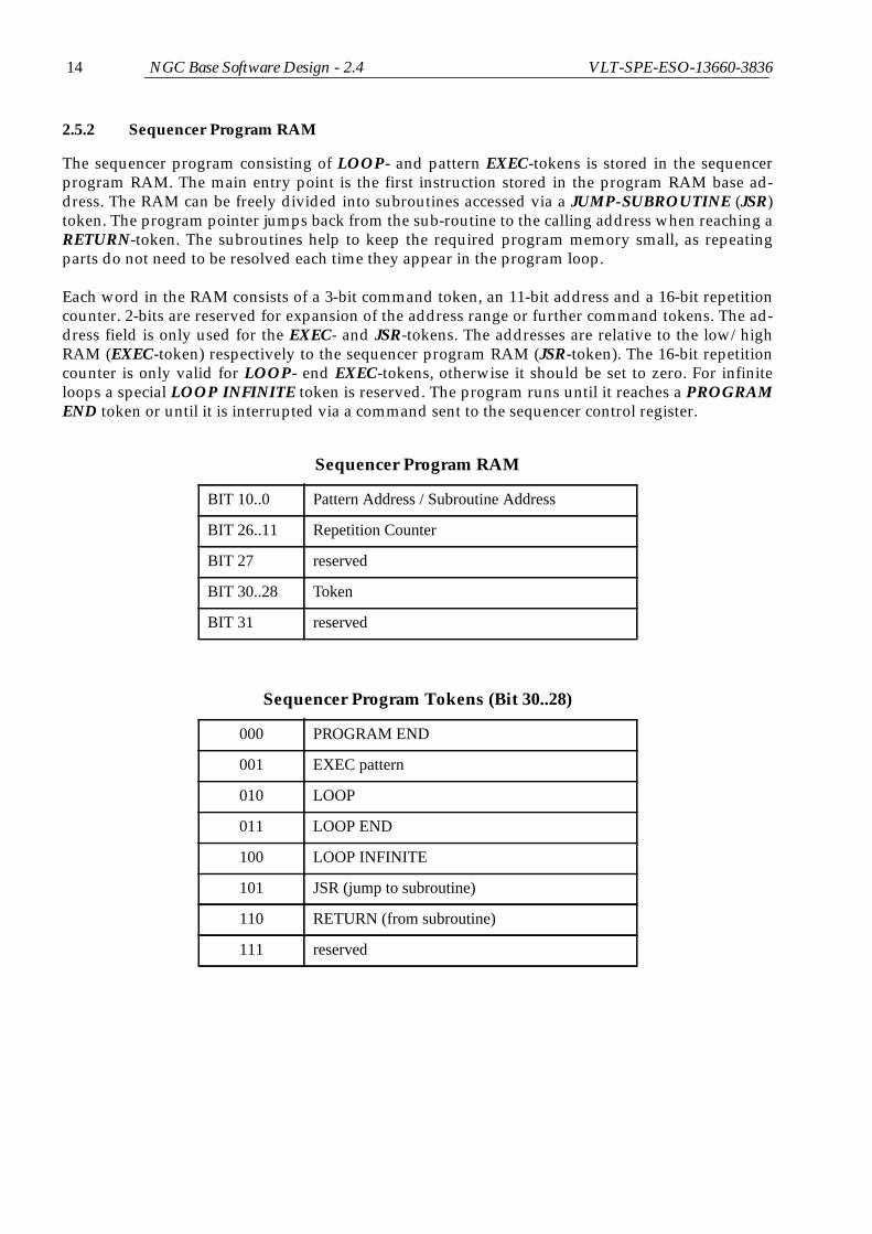
2.5.2 Sequencer Program RAM
The sequencer program consisting of LOOP- and pattern EXEC-tokens is stored in the sequencerprogram RAM. The main entry point is the first instruction stored in the program RAM base ad-dress. The RAM can be freely divided into subroutines accessed via a JUMP-SUBROUTINE (JSR)token. The program pointer jumps back from the sub-routine to the calling address when reaching aRETURN-token. The subroutines help to keep the required program memory small, as repeatingparts do not need to be resolved each time they appear in the program loop.
Each word in the RAM consists of a 3-bit command token, an 11-bit address and a 16-bit repetitioncounter. 2-bits are reserved for expansion of the address range or further command tokens. The ad-dress field is only used for the EXEC- and JSR-tokens. The addresses are relative to the low/highRAM (EXEC-token) respectively to the sequencer program RAM (JSR-token). The 16-bit repetitioncounter is only valid for LOOP- end EXEC-tokens, otherwise it should be set to zero. For infiniteloops a special LOOP INFINITE token is reserved. The program runs until it reaches a PROGRAMEND token or until it is interrupted via a command sent to the sequencer control register.
Sequencer Program RAM
BIT 10..0 Pattern Address / Subroutine Address
BIT 26..11 Repetition Counter
BIT 27 reserved
BIT 30..28 Token
BIT 31 reserved
Sequencer Program Tokens (Bit 30..28)
000 PROGRAM END
001 EXEC pattern
010 LOOP
011 LOOP END
100 LOOP INFINITE
101 JSR (jump to subroutine)
110 RETURN (from subroutine)
111 reserved

NGC Base Software Design - 2.4 VLT-SPE-ESO-13660-3836 15
2.6 Sequencer Control
The sequencer is started by setting either the start bit or the start-sync bit in the sequencer controlregister. If the start-sync bit is used, then the synchronous start signal is raised and all sequencer in-stances will be started synchronously unless they have the external-run-control disable bit set in theircontrol register. This also applies to the initiating sequencer (i.e. the sequencer may raise the start-sync bit but not start itself when the external run-control is disabled). The normal start-bit will al-ways start the sequencer, even if external run-control is disabled.
The sequencer stops after the dwell time of the pattern currently executed in the following cases:
• The address FIFO becomes empty (error condition).
• The stop bit is set in the sequencer control register.
• A PROGRAM END token is executed.
• The break bit is set in the sequencer control register and a pattern state is executed, which hasalso the break bit set in its high RAM word. The reaching of such a break point can be tracedby polling the sequencer status register.
2.7 Synchronization
The program execution is suspended when a pattern state was executed, which had the “wait fortrigger bit” set in its high RAM word, and the trigger mode is enabled in the sequencer control regis-ter. Program execution is resumed upon the reception of the external trigger signal or when the trig-ger bit is set by software in the sequencer control register. By using the “wait for-trigger bit” it ispossible to synchronize detector read-outs with external events or also to synchronize programsrunning on multiple sequencer modules with high accuracy. The external trigger signal has to begenerated by an external dedicated hardware. Using the VLT TIM for this purpose allows external-ly controlled timings which are synchronous with the VLT time reference signal. As the “wait fortrigger” state can also be disabled by setting the trigger-mode bit in the sequencer control register tozero, it is possible to run exactly the same clock pattern sequence either continuously or triggeredexternally.
Some signal lines in the sequencer clock pattern RAM can be used to create feed-back signals (“endof read-out”) to in turn trigger external devices.

16 NGC Base Software Design - 2.4 VLT-SPE-ESO-13660-3836

NGC Base Software Design - 2.4 VLT-SPE-ESO-13660-3836 17
3 SOFTWARE ARCHITECTURE
3.1 Hierarchy
The software can be classified hierarchically as shown in Figure 4.
Figure 4 Software Hierarchy
open()close()read()write()ioctl()
Reset()/Initialize()SetTimeout()
ReadBuffer(address,buffer,size,...)WriteBuffer(address,buffer,size,...)
SingleDmaRead()ConfigureSustainedDma()
StartSustainedDma()WaitForData()
AbortSustainedDma()GetDmaStatus()
...
SetVoltage()ReadTelemetry()
EnableVoltageOutput()SetClockPattern()GetClockPattern()StartSequencer()StopSequencer()
EnableAdc()/DisableAdc()...
StartAcquisition()StopAcquisition()RequestImage()ReceiveImage()
...
CaptureData()ProcessData()TransferData()
...
ConfigureSystem()SetReadoutMode()SetupExposure()StartExposure()AbortExposure()CreateFitsFile()
UpdateDatabase()DisplayImage()
...
Graphical User Interface
Driver Level
DriverInterface
Level
ControllerInterface
Level
Control-Server
AcquisitionProcess
Level
SystemData Acquisition Communication
mmap()

18 NGC Base Software Design - 2.4 VLT-SPE-ESO-13660-3836
3.2 Software Modules
All software modules are under CMM configuration control. The base software contains the follow-ing software modules:
• ngcdrv - The device driver for the PCI-Bus back-end card.
• ngcb - The NGC basic software module containing the driver interface library (ngcbDrv)for communication and DMA, some basic i/o tools, a portable threads- andpriority-control implementation and the C++ base classes for general systemaccess. This module also provides a hardware simulation mechanism for the NGCcontroller (see section 5.3).
• ngcpp - The DMA data-acquisition and pre-/processing module.
• ngcdcs - The NGC detector control software base module implementing the classes for theNGC hardware modules and the interfaces to the data acquisition (Figure 5).
A dictionary, which is common to both infrared and optical systems, is stored in the dicNGC soft-ware module.
The software module ngcarch provides automatic installation procedures for all the mentioned soft-ware modules (see Figure 6).
3.3 Test Software
Test scripts for the TAT (see [RD41]) are developed in parallel to the software module code genera-tion. Test configuration files are created for various virtual system architectures and detector assem-blies to cover all possible ranges of complexity. The DMA data-acquisition and pre-/processingmodule ngcpp does not contain TAT test scripts, but fully working test/template acquisition pro-cesses instead, which are then embedded in the test scripts and test configuration files of the higherlevel ngcdcs module.
3.4 Class Structure
The Sequencer-, CLDC- and ADC- hardware modules are modelled in the ngcdcs software moduleas C++ objects (ngcdcsSEQ, ngcdcsCLDC, ngcdcsADC). They all inherit from a base module class(ngcbMOD, see 6.1), which keeps the physical interface (ngcbIFC, see 5.1) including the route to themodule. Hardware simulation is implemented via a simulator class (ngcbSIM, see 5.3), which is anobject within the ngcbIFC class. The ngcdcsCTRL class is a container class for all these hardwaremodules. Interface classes for controlling the data acquisition process (ngcdcsACQ) and for the datatransfer (ngcdcsACQ_DATA) are also part of the ngcdcs module. The ngcbOBJ class is a base classunifying some common tasks for the controller classes and the acquisition module classes.

NGC Base Software Design - 2.4 VLT-SPE-ESO-13660-3836 19
Figure 5 Class Structure
Figure 6 Module dependencies
ngcbIFC
ngcbIFC_XXX
ngcbMOD
ngcdcsCLDC ngcdcsSEQ ngcdcsADC
ngcbSIM
ngcdcsACQ
ngcdcsACQ_DATA
ngcbOBJ
ngcdcsCTRL
ngcbIFC_MSG
1..* 1..* 1..* 1..*Inherits from
Instantiates
ngcdcsSRV/EVH
evhTASK
ngcbngcbDrvngcbIFC, ngcbSIMngcbOBJngcbMODngcbTHREAD,...
ngcpp
ngcdcs...SEQ...CLDC...ADC
...ACQ_DATA
...ACQ
...EVH
...Server
ngcir... ngco...
(infrared specific) (optical specific)
ngcarch
ngcdic
Depends on

20 NGC Base Software Design - 2.4 VLT-SPE-ESO-13660-3836
3.5 Verbose Mode and Logging
Verbose messages can be printed on the standard output stream of each process. The detail is givenby a verbose level, which is also passed as parameter to the respective sub-processes. To make themessages of the sub-processes visible, it is required to start those processes in a separate terminal.
Error - logging will be done with the standard CCS error logging facility, which includes the auto-matic logs like tracing of any received/sent command (see [AD27], [RD32]). Additionally the ver-bose output can be logged in a detail depending on a given log-level for maintenance/debuggingpurposes. Operational logs are TBD.
3.6 Error Handling
The CCS error mechanism [RD32] provides a classification scheme for application specific errors.The NGC base software uses this mechanism. The introduction of new error codes is limited to cas-es, where specific actions (“reset”, “restart server”, “restart CCS environment”, “reboot” etc.) are re-quired. Other errors, which leave the system still in a valid state without further interaction(“parameter out of range”, “invalid file name”,...) are trapped by an overall system error(ngcbERR_SYSTEM, ngcdcsERR_SYSTEM) plus an appropriate message string. The meaning of theerror class and the possibly needed interactions are described in a help file (.hlp), which can be dis-played with the standard CCS-tools (also with the logMonitor). The actual error reason (“timeout”,“link channel error”,...) is given in an associated error message string.
Error Severity Description
ngcbERR_SYSTEM Warning General error of informative character (“parameter out ofrange”, “invalid file name”, etc.).
ngcbERR_IO Serious An I/O-error on the interface to the detector front endoccurred. Typically this will require at least a reset or apower-cycle of the NGC hardware to recover.
ngcbERR_SRV Serious The communication with the driver interface process hasfailed. The server may have died or the message system/net-work is down.
ngcbERR_INIT Serious The server initialization failed. The message system maynot be up, or the operating system has run out of itsresources. This may require a restart of the environment oreven a reboot of the IWS/NGC-LCU.
ngcbERR_WARNING Warning A warning which has only very limited effect on the furthersystem behaviour.

NGC Base Software Design - 2.4 VLT-SPE-ESO-13660-3836 21
ngcbERR_DB_READ Serious Error when reading from the online database. This mayrequire a rebuild of the database and a restart of the CCSenvironment.
ngcbERR_DB_WRITE Serious Error when writing to the online database. This may requirea rebuild of the database and a restart of the CCS environ-ment.
ngcbERR_DB_INIT Serious Error when reading from or writing to the online databaseduring initialization phase. This may require a rebuild of thedatabase and a restart of the CCS environment.
Error Severity Description
ngcdcsERR_SYSTEM Warning General error of informative character (“parameter out ofrange”, “invalid file name”, etc.)
ngcdcsERR_IO Serious An I/O-error on the interface to the detector front endoccurred. Typically this will require at least a reset or apower-cycle of the NGC hardware to recover.
ngcdcsERR_INIT Serious The server initialization failed. The message system maynot be up, or the operating system has run out of itsresources. This may require a restart of the environment oreven a reboot of the IWS/NGC-LCU.
ngcdcsERR_WARNING Warning A warning which has only very limited effect on the furthersystem behaviour.
ngcdcsERR_FATAL Fatal An error which cannot be recovered in any case.
ngcdcsERR_DB_READ Serious Error when reading from the online database. This mayrequire a rebuild of the database and a restart of the CCSenvironment.
ngcdcsERR_DB_WRITE Serious Error when writing to the online database. This may requirea rebuild of the database and a restart of the CCS environ-ment.
Error Severity Description

22 NGC Base Software Design - 2.4 VLT-SPE-ESO-13660-3836
ngcdcsERR_DB_INIT Serious Error when reading from or writing to the online databaseduring initialization phase. This may require a rebuild of thedatabase and a restart of the CCS environment.
ngcdcsERR_ACQ_IO Serious An I/O-error occurred when communicating with the acqui-sition process. The process may have died or the networkconnection to the NGC-LCU may be broken.
ngcdcsERR_ACQ_OVERRUN Serious The acquisition process was not able to process the data intime. All data are buffered in a ring-buffer to compensateoperating system gitters. If data are coming in faster thanthey can be processed for a longer period, then the ring-buffer may overrun. Either read-out slower or add sufficientdelays between the readouts.
ngcdcsERR_ACQ_OVERFLOW Serious The data on the physical NGC-data link are coming infaster, than they can be delivered to the computer bus. Theinternal FIFOs on the interface boards become full in thiscase. This is a hardware error. The reason may be for exam-ple crosstalk/spikes on the physical communication lines.
ngcdcsERR_EXP_IO Serious An error occurred during data taking. The data connectionto the acquisition process may be broken (process has diedor network is down).
ngcdcsERR_EXP_FILE Serious An error occurred when writing the exposure data to a fileon the disk. The disk may be full or the directory can nomore be accessed.
Error Severity Description

NGC Base Software Design - 2.4 VLT-SPE-ESO-13660-3836 23
4 DEVICE DRIVER
The PCI-Bus back-end card is the interface between the NGC detector front-end and the PCI-Bus onthe NGC-LCU. It provides both a communication channel (COM-port) for setup and status com-mands and a high speed scatter/gather DMA channel for ring-buffered sustained data transfer. Thedevice driver for this module is delivered in the ngcdrv module. If no interface card is used (e.g.software is used only for simulation purposes), then the device driver needs not to be installed.
The device driver supports Linux Kernel 2.4 and 2.6 (or later). The Makefile of the ngcdrv modulealso takes care of the differences between Linux 2.4 and Linux 2.6 kernels. Compilation and installa-tion can simply be done with “make all install” on both kernel version trees. A script to install(ngcdrv_load) and to remove (ngcdrv_unload) the driver is part of the ngcdrv module. The installscript may be added to the /etc/rc.local file to let the driver be loaded at boot time. The compilationand installation of the driver module has to be done as user “root” on a directory which is local onthe target computer. Path and environment need to be reset to the root home session.
CAUTION: Use “rlogin $HOST -l root”, “telnet $HOST” or “su -”, to login as root. The frequentlyused “su” (without “-”) does not setup a proper root session and the loading of the driver module(ngcdrv_load) may fail with an error message indicating an “invalid module format”.
The device driver provides the standard system calls (open, close, read, write, ioctl, mmap) for sev-eral instances (boards) installed on the host-computer. A channel to a device can be opened withthe open system call. The device name is typically “/dev/ngc<n>_com” for the communication chan-nel and “/dev/ngc<n>_dma” for the DMA channel, whereby <n> is the instance number (startingwith 0) of the board.
(int) fd = open(“/dev/ngc<n>_com”, O_RDWR);(int) fd = open(“/dev/ngc<n>_dma”, O_RDWR);
If the open call fails, a negative value is returned and the appropriate errno is set. The close systemcall is used to close a channel to a device:
(int) status = close((int) fd);
The function returns 0 in case of successful operation. Otherwise a negative value is returned andthe appropriate errno is set.
The driver also supports the execution of a single DMA read. This transfer can be done through thestandard read system call.
4.1 NGC Communication Channel
The communication channel is operated through the read/write system calls. A timeout for theseoperations can be specified via an ioctl command. The default timeout value is zero, which meansthat the timeout is disabled. A reset of the target device can also be performed via ioctl. The read/write is done using a polling mechanism.
4.2 DMA Data Acquisition
DMA transfers are done via scatter/gather lists. Large DMA transfers are cut into small pieces andan array of DMA-descriptor blocks holds the address and the size for each part (see Figure 7). Thelast entry in a descriptor block contains the address and the flags of the next descriptor to be loadedinto a DMA Descriptor Address Register. The flags contain information about the direction of the

24 NGC Base Software Design - 2.4 VLT-SPE-ESO-13660-3836
transfer (Local Bus to PCI Bus or vice versa) and whether an interrupt should be generated after thetransfer or not. An ‘end-of-chain’ flag marks the end of the list. A sustained mode (ring buffer mode)is possible by setting the address of the first descriptor in the ‘next descriptor address’ field of the lastdescriptor in the chain (without setting the ‘end-of-chain’ flag). If a ring-buffer consist of N elementsspecified by the calling application, the driver would divide each element into smaller pieces ofDMA. An interrupt is only generated when the last piece for one ring-buffer element has been trans-ferred. The actual layout of the scatter/gather list is fully transparent to the user.
Figure 7
The DMA memory is allocated by the driver in kernel space and the corresponding pages aremapped into the user space via the mmap system call. First the driver is told via an ioctl system callhow many ring-buffer elements to allocate in kernel space:
ngcdrv_ring_t ring;
ring.nbuf = <number of buffers>;ring.size = <size of each buffer>;
ioctl ((int) fd, NGCDRV_DMA_CFG_BUF, (void *)&ring);
Then the memory has to be mapped into the user space via the mmap system call. The number ofring-buffer elements actually allocated might differ from the value passed to the driver. Therefore
Next Descriptor Address Flags
PCI-Bus Address of DMA Buffer
Local Bus Address
Transfer Size
PCI-Bus Address of DMA Buffer
Local Bus Address
Transfer Size
Next Descriptor Address Flags
PCI-Bus Address of DMA Buffer
Local Bus Address
Transfer Size
Next Descriptor Address Flags
Next Descriptor Address Flags
DMA Descriptor Address Register
...
(Continuous Mode)
First Descriptor
Last Descriptor
(End of Transfer)
Second Descriptor
Interrupt

NGC Base Software Design - 2.4 VLT-SPE-ESO-13660-3836 25
the value returned in the ring-structure must be used for the mapping:
(void *)mapArea = mmap(0,(int)(ring.size*ring.nbuf),PROT_READ,MAP_SHARED,(int)fd,0);
The function returns a (virtually) contiguous memory area holding the specified number of ring-buffer elements or MAP_FAILED if an error has occurred. The user space buffers are then obtainedin the following way:
if (mapArea != MAP_FAILED) { int i; mapSize = ring.size * ring.nbuf; for(i=0;i<ring.nbuf;i++) { buffer[i] = (char *)(mapArea + (i * ring.size)); } }
The memory is released in the user space by un-mapping the reserved area:
if (mapSize > 0) { munmap(mapArea, mapSize); }
The buffer addresses should be set to NULL afterwards:
for (i=0;i<ring.nbuf;i++) { buffer[i] = (char *)NULL; }
4.3 Commands
The ioctl system call is used to send a command to a device:
(int) status = ioctl((int) fd, (int) command, [(void *)argument]);
The function returns 0 in case of successful operation. Otherwise -1 is returned and the appropriateerrno is set. The following ioctl commands are supported by the device driver. The command liter-als are defined in the device driver header file (ngcdrv.h).
• NGCDRV_PCFG_GET reads a register value from the PCI configuration space;
The argument is a pointer to an ngcdrv_param_t structure:
unsigned int reg; - not usedunsigned int value; - returns the register valueunsigned int offset; - PCI configuration address
• NGCDRV_PCFG_SET sets a register value in the PCI configuration space;
The argument is a pointer to an ngcdrv_param_t structure:
unsigned int reg; - not usedunsigned int value; - register value

26 NGC Base Software Design - 2.4 VLT-SPE-ESO-13660-3836
unsigned int offset; - PCI configuration address
• NGCDRV_CFG_GET reads a register value from the device configuration space;
The argument is a pointer to an ngcdrv_param_t structure:
unsigned int reg; - not usedunsigned int value; - returns the register valueunsigned int offset; - offset from configuration base address
• NGCDRV_CFG_SET sets a register value in the device configuration space;
The argument is a pointer to an ngcdrv_param_t structure:
unsigned int reg; - not usedunsigned int value; - register valueunsigned int offset; - offset from configuration base address
• NGCDRV_COM_RESET resets the target device and clears the COM-port FIFOs;
No argument.
• NGCDRV_COM_TMO sets a timeout for subsequent read/write calls on a COM-port device;
The argument is a pointer to an unsigned int specifying the timeout in seconds. The defaultvalue is zero, which means that the timeout is disabled.
• NGCDRV_DMA_RESET resets (clears) the DMA data FIFO;
No argument.
• NGCDRV_DMA_CFG_BUF configures the ring-buffer mode on a DMA device (Linux only);
The argument is a pointer to an ngcdrv_ring_t structure:
unsigned int nbuf; - number of ring-buffer elementsunsigned long size; - size (in bytes) of each buffer
This command is only valid when using the Linux operating system.
• NGCDRV_DMA_START starts a continuous ring-buffered scatter-gather DMA;
No argument.
• NGCDRV_DMA_WAIT waits for the next ring-buffer interrupt;
No argument. The interrupts are buffered internally. If the calling function has missed aninterrupt, the ioctl call returns immediately.
• NGCDRV_DMA_DONECOUNT returns the current buffer counter;
The argument is a pointer to an unsigned int containing the current buffer counter. The counteris initialized to zero with the NGCDRV_DMA_START ioctl command. It wraps with the rangeof an unsigned 32-Bit integer.

NGC Base Software Design - 2.4 VLT-SPE-ESO-13660-3836 27
• NGCDRV_DMA_BYTECOUNT returns the number of bytes left in the current DMA;
The argument is a pointer to an unsigned int containing the current byte counter. Currentlythis functionality is not supported by the device hardware.
• NGCDRV_DMA_ABORT aborts a sustained ring-buffered scatter-gather DMA;
No argument.
• NGCDRV_DMA_OVERFLOW checks the DMA-FIFO full flag;
The argument is a pointer to an unsigned int returning a non zero value if the DMA input FIFObecame full. The input FIFO full flag is cleared with an NGCDRV_DMA_START ioctlcommand or when a single DMA read is performed.
4.4 Driver Interface Libraries
The driver functionality is assembled in a driver interface library (ngcbDrv) consisting of two majorparts for the communication with the system (ngcbDrvCom) and the DMA data-acquisition (ngcb-DrvDma). This library is intended to give a stable procedural interface to the driver, while the de-vice driver itself is subject to updates forced by changes in the peripheral buses and or by newkernel versions or operating system patches. See sections 1.2 and 1.3 for an overview of the sup-plied functions. The “ngcbAddr.h” header file contains all information concerning register addressesand bit-masks for register contents.

28 NGC Base Software Design - 2.4 VLT-SPE-ESO-13660-3836

NGC Base Software Design - 2.4 VLT-SPE-ESO-13660-3836 29
5 NGC INTERFACE CLASS
On top of the device driver interface library (ngcbDrv) the NGC interface class is intended to pro-vide the basic entry point for the C++ programmer.
5.1 Interface Base Class
The physical interface is represented in the ngcbIFC class. The class provides methods for opening/closing/resetting the device and for writing data to an address or reading data from an address of amodule function in an NGC front-end network which is connected through this interface. All NGCregisters/memory can be accessed by calls to the ReadAddr(), WriteAddr() member functions. ThengcbIFC class hides all implementation details, which can be customized by overloading the Open(),Close(), Reset(), ReadAddr(), WriteAddr() methods. The intention is to have a transparent representa-tion of these methods, regardless whether they are called locally on the NGC-LCU or remotely onthe IWS (Figure 8), which in the latter case would implement these functions as a network protocolwithin a client/server environment. In case the NGC is controlled remotely from the IWS, the driv-er interface process running on the NGC-LCU is a lightweight process, which needs to support onlya very limited set of commands like ONLINE (open device), STANDBY (close device), RESET,RDADDR (read from address), WRADDR (write to address), regardless of the complexity of the de-tector front-end system behind and regardless of the complexity of the executed function. In casethe software has to be ported to whatever protocol, only the ngcbIFC_XXX class and the commandhandler of the driver interface process have to be replaced, while all higher level functionality canremain untouched. The methods will take care of byte-swapping between big endian and little en-dian computing architectures and will keep all device handles (such as file descriptors, messagequeues etc.) internal. So the task for the instantiating application is reduced to its actual basic func-tion, which is read/write access to addresses in the NGC detector front end.
Figure 8 Interface Classes
The normal application will be to run the SW distributed on IWS/NGC-LCU. To run the control-
ngcbIFC
interface->ReadAddr()interface->WriteAddr()
ngcbIFC_XXX
DriverInterfaceProcess_XXX:
interface->ReadAddr()interface->WriteAddr()
DeviceDriver
ngcbIFC
interface->ReadAddr()interface->WriteAddr()
ControlServer:
ControlServer:
Protocol_XXXHandle
Command
Running locally on NGC-LCU
Running somewhereRunning locally on NGC-LCU
DeviceDriver

30 NGC Base Software Design - 2.4 VLT-SPE-ESO-13660-3836
server locally on the NGC-LCU is mainly intended for HW-development and detector tests in thelaboratory, where one does not have access to an IWS in each particular case.
Two virtual methods (ExecServer()/KillServer()) are supplied to execute/kill the driver interface pro-cess in an application defined way. For the default local interface implemented by the ngcbIFC classthese methods are empty. In case a driver interface process is used the Connect()/Disconnect() meth-ods will instruct this process to open/close the connection to the physical device, while the Open()/Close() methods will open/close a connection between control server and driver interface process. Ifthe interface is local, then the Connect()/Disconnect() methods are implemented just as Open()/Close() calls. The convenience methods Online(), Standby() and Off() will take care to call the Exec-Server()/KillServer(), Open()/Close() and Connect()/Disconnect() methods in the right way for switch-ing the interface state regardless whether the physical interface is local or not. The method
int ReadAddr(ngcb_route_t route, int address, int *buffer, int size, int *result);
reads size 32-bit words from address into buffer. The method
int WriteAddr(ngcb_route_t route, int address, int *buffer, int size, int *result);
writes size 32-bit words from buffer to address.
The ngcb_route_t structure contains the following elements:
int numHdr; - number of headers to target including the terminating <0x2>int hdr[ngcbMAX_MOD];- array of headers including the terminating <0x2>
Both operations implement a 4-byte swap in case the calling computer has a big-endian architecture.The methods take care of splitting up the operation into a sequence of read()/write() calls in case thebuffer size exceeds the maximum size for a single operation (Rx-/Tx-FIFO size, see section 2.3). Theresult returns a 32-bit status word for the executed operation. An error string can be retrieved via theResult2Err() method. The status word may have the following values:
ngcbRES_SUCCESS (0) - successful operation
Bit 0..7 contain the operation status byte (ngcbRES_ERR_IO bit is not set):
ngcbRES_OP_INVALID - invalid address or functionngcbRES_OP_FAILURE - operation failedngcbRES_ERR_HDR - wrong headerngcbRES_ERR_ADDR - wrong addressngcbRES_ERR_DATA - wrong datangcbRES_ERR_XSIZE - wrong transfer sizengcbRES_ERR_NOT_OPEN - device is not open
Bit 8..16 contain a combination of the following i/o error bits (ngcbRES_ERR_IO bit is set):
ngcbRES_ERR_IO - i/o errorngcbRES_ERR_INTR - i/o interruptedngcbRES_ERR_OPEN - error opening devicengcbRES_ERR_RESET - error resetting devicengcbRES_ERR_TIMEOUT - i/o timeoutngcbRES_ERR_LINK_DOWN - link channel downngcbRES_ERR_LINK_HARD - link channel hard errorngcbRES_ERR_LINK_SOFT - link channel soft error

NGC Base Software Design - 2.4 VLT-SPE-ESO-13660-3836 31
5.2 Interface Instantiation
The interface is constructed by passing a name-string as constructor-argument. Then it can beopened and closed by calling the Open()/Close() methods with no argument. The methodOpen(name) will also open the interface, but additionally it sets a new name. The name is identical tothe device name in case the interface is local. For interfaces using a driver interface process, thename is an application specific string passing the information needed to start the process on the ap-propriate computer. Typically the string is formed out of the host name, the environment name andthe server name, where the latter may be set to a hard coded default server name when the field ismissing. The driver interface process may require certain command line arguments (this could bethe device name of the physical interface device). The Arg() methods returns a pointer to a string,which is intended to be passed to the process as command line within the ExecServer() method.
This instantiation scheme is not obligatory, as the Open()/Close() and ExecServer()/KillServer() meth-ods may handle this in an arbitrary way. The basic ngcbIFC_MSG class delivered with the ngcbmodule uses this scheme for a client/server implementation based on the CCS-message system[AD25]. The driver interface process (ngcb2Drv) running locally on the NGC-LCU is based on theEVH-toolkit (see [RD33] and [RD35].
Figure 9 Interface Instantiation
5.3 NGC Simulator Class
The hardware simulation should be done at the lowest possible level to allow all higher level soft-ware functions to be tested without having access to the physical device. The IRACE approach (see[RD16]) was to have a dedicated simulator process playing the role of the electronics. Instead ofwriting the messages to the device driver, the i/o was done through socket communication withthis simulator process. Although this is the maximum level of separation, the introduction of puresimulation specific administrative functionality (process startup, two-way protocol conversion...)imposes an unwanted heaviness to this solution. In FIERA (see [RD15]), a first approach also hadbeen to have a process simulating the detector, with the drawback that often the real code and thesimulation code were misaligned. For this reason, the dedicated process playing the role of the elec-
ngcbIFC
interface->ReadAddr()interface->WriteAddr()
ngcbIFC_MSG
ngcb2Drv:
interface->ReadAddr()interface->WriteAddr()
DeviceDriver
ngcbIFC
interface->ReadAddr()interface->WriteAddr()
ControlServer:
ControlServer:
CCS MessageHandle
Command
Running locally on NGC-LCU
Running somewhere Running locally on NGC-LCU
DeviceDriver
System

32 NGC Base Software Design - 2.4 VLT-SPE-ESO-13660-3836
tronics has been soon removed. The different processes directly simulated the command executiontiming before replying to the higher level software, assuming a successful execution of the com-mand by the electronics.
The NGC hardware simulation is done through a C++ class (ngcbSIM), which is directly instantiat-ed in the ngcbIFC class. This object-oriented approach still provides a good level of separation, butavoids the additional protocol conversion effort. The only costs are a few conditional statementsaround the basic calls to the driver interface library functions, switching between the “real” read()/write() functions and the ngcbSIM::Read()/ngcbSIM::Write() member functions of the simulator class.
An instance of the ngcbSIM class is created inside the (local) ngcbIFC interface class when calling theSim() member function with the argument ‘1’. In case of a non-local interface the simulation flag hasto be propagated to the driver interface process via a command (SIMULAT/STOPSIM), whichwould instruct the process to call the Sim() method on its local ngcbIFC instance.
The simulator configures itself dynamically via the system headers sent with the write() system call.A new simulator object is created recursively for every NGC hardware module defined via the linkconfiguration register (header 0x8). It provides all NGC hardware registers including sequencer pat-tern- and program-RAM. The voltage setting is sloped to the telemetry values via the DAC - ADCconversion function. The message packets are routed to the right destination instance using the in-formation in the routing headers. The result is automatically passed back recursively to the main en-try point (first ngcbSIM instance). The synchronous sequencer start signal (physically on an externalline) is propagated to all ngcbSIM instances. Time-outs and errors can be emulated by accessing un-used addresses at any module instance:
ngcbTESTERR_NO_ACK (0x100) - no acknowledgengcbTESTERR_IVLD (0x104) - invalid addressngcbTESTERR_SEQ_EMPTY (0x200) - sequencer FIFO becomes emptyngcbTESTERR_SEQ_IDLE (0x201) - sequencer goes to IDLE state (sequence has termi-
nated)
Further error cases may be added (TBD).
Once verified the ngcbSIM class allows all software including the ngcbIFC class itself to be fully test-ed in simulation mode.

NGC Base Software Design - 2.4 VLT-SPE-ESO-13660-3836 33
6 NGC SOFTWARE CLASSES
6.1 Module Base Class
The NGC detector front-end is modular in a sense, that it might consist of an arbitrary number ofsequencers, CLDC modules and ADC modules which are linked together in a network-like struc-ture. To realize this modularity also in the controlling software all hardware modules are imple-mented in an object oriented way using C++ classes.
All hardware modules have in common, that their registers are accessed via a chain of headers lead-ing from one physical board to the other. To access a function on a certain hardware module, one al-ways needs to specify the register address of the function and the route of headers leading tophysical board where the module resides. For large systems it will be required to spread the systemcontrol among several PCI-Bus interface cards on the same or even on different hosting computers.To support also these architectures, the hardware modules have additionally to be addressed viaboth the ngcbIFC object (through which this part of the front-end is accessed) and the chain of head-ers (route) leading to the module. The hardware module base class (ngcbMOD) is constructed withthe arguments (ngcbIFC *interface, ngcb_route_t route). The sequencer-, CLDC- andADC classes all derive from this hardware module base class and from now on their individualfunctions can be easily modelled using simple ReadAddr()/WriteAddr() calls with the only argu-ments address and data[].
Figure 10 Module Function Call
The board temperature of each hardware module can be retrieved using the Temperature() memberfunction. The Initialize() member function reads all relevant board information (serial number,product code, revision) from the hardware. The product information is stored in public data mem-bers and can be used to introduce revision specific behavior to the derived classes.
mySequencer->Start()
ngcbMOD::WriteAddr(0x6000, 0x1)
myDevice->WriteAddr(route, 0x6000, 0x1)
ngcdcsSEQ *mySequencer = new ngcdcsSEQ(myDevice, route);
ngcbIFC *myDevice = new ngcbIFC(deviceName); /* or: new ngcbIFC_XXX(deviceName) */
ngcb_route_t route = {3, {0x5, 0x6, 0x2}};
ngcbComWrite(myDevice->fileDescriptor, (char *)(int []){0x5, 0x6, 0x2, 0x0, 0x6000, 0x1}, 6, errMsg);
write(myDevice->fileDescriptor, (char *)(int []){0x5, 0x6, 0x2, 0x0, 0x6000, 0x1}, 6);/* check status and error conditions *//* fill errMsg, if operation failed */

34 NGC Base Software Design - 2.4 VLT-SPE-ESO-13660-3836
6.2 Parameter Model
In the NGC base software a parameter class (ngcbPARAM) is defined in order to associate specificbehavior of the sequencer and acquisition modules to the setting of a parameter value. The parame-ter storage type is given in the constructor. A Set() method exists for all common types to set a newvalue. The class takes care for all possible type conversions. An internal flag traces all parameterchanges. The Get() method always returns a formatted string value. The class contains the followingpublic data members:
char name[64]; - parameter name
char alias[64]; - one alias name for the parameter
char format[16]; - format for output of the Get(),ValString() methods.
int fits; - flag to put the parameter into the FITS-header
char comment[44]; - optional comment for FITS-header
char unit[8]; - optional unit string
int flag; - storage space for application specific flags (initial value is 0)
int ctrlList; - controller modules (sequencer), where the parameter is used. This is a bit-list main-taining up to 32 controller modules (bit 0 for 1st. module, bit 1 for 2nd. module andso on).
int acqList; - acquisition-processes, where the parameter is used. This is a bit-list maintaining upto 32 acquisition processes (bit 0 for 1st. module, bit 1 for 2nd. module and so on).
The bit-lists (ctrlList, acqList) of a parameter help to decide whether the sequencer has to be reloadedor not after a new setup or whether for example the acquisition process has to be re-synchronized(see sections 6.3 and 7.2.2). The format, unit, fits and comment data members are intended to be im-ported from dictionaries by the using applications (control server).
The parameters are maintained in a dynamic linked list (ngcbPARAM_LIST class). Parameters canbe added and removed with the Add()/Remove() member functions. The list is always NULL-termi-nated. In order to walk through the list one can use the following construct:
for (l=list.First();l!=(ngcbPARAM_LIST *)NULL;l=l->next) { ngcbPARAM *p = l->param; printf("%s = %s %d %f\n", p->name, p->Get(), p->ValInt(), p->ValFloat()); }
There are two convenience member functions to clear the instance bits of a sequencer module or ofan acquisition module from all parameters in the list: ClrCtrlList(instance) and ClrAcqList(instance). Ifboth bit-lists are zero (empty), then the parameter is automatically removed from the parameter list.
NGC Base Software Design - 2.4 VLT-SPE-ESO-13660-3836 35
6.3 Sequencer Module Class
The ngcdcsSEQ class provides all functions to setup and control a sequencer module.
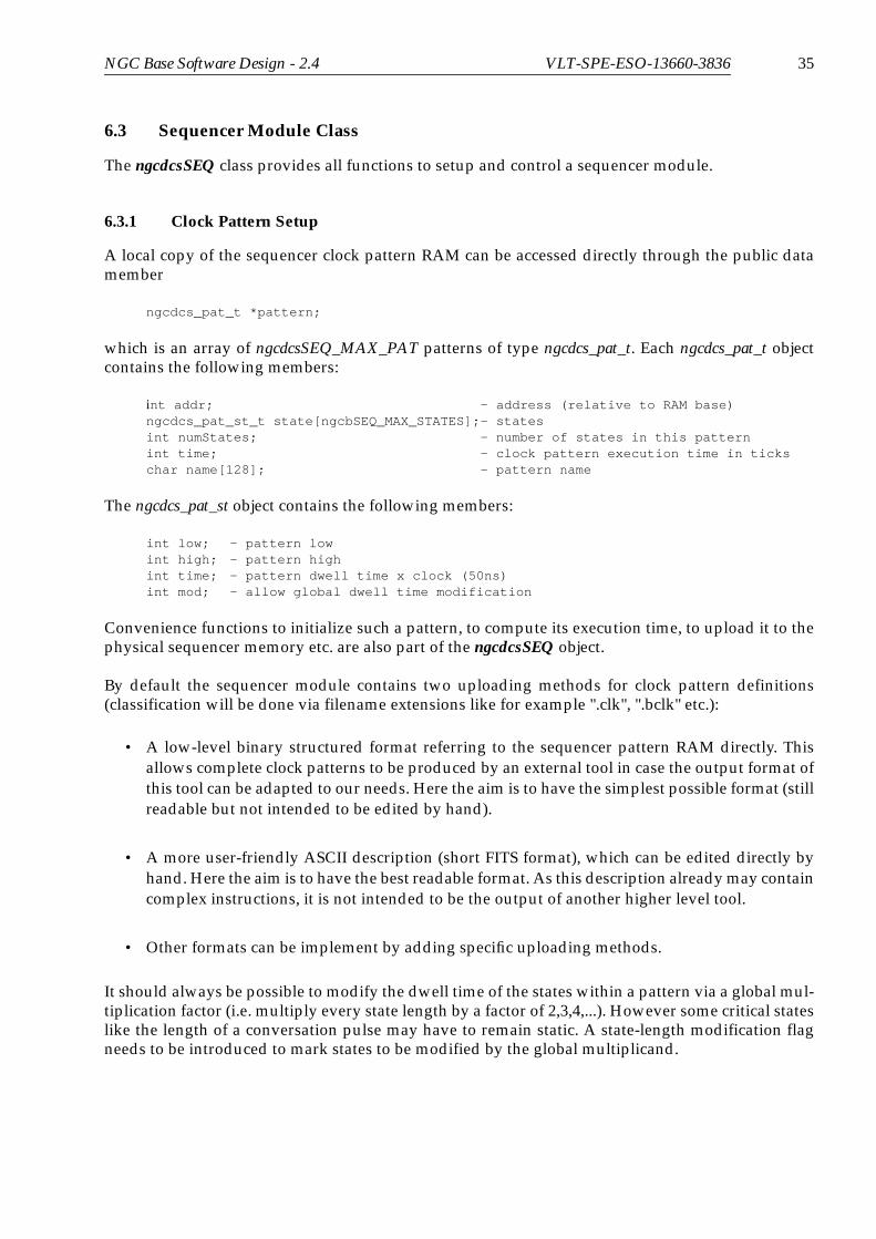
6.3.1 Clock Pattern Setup
A local copy of the sequencer clock pattern RAM can be accessed directly through the public datamember
ngcdcs_pat_t *pattern;
which is an array of ngcdcsSEQ_MAX_PAT patterns of type ngcdcs_pat_t. Each ngcdcs_pat_t objectcontains the following members:
int addr; - address (relative to RAM base)ngcdcs_pat_st_t state[ngcbSEQ_MAX_STATES];- statesint numStates; - number of states in this patternint time; - clock pattern execution time in tickschar name[128]; - pattern name
The ngcdcs_pat_st object contains the following members:
int low; - pattern lowint high; - pattern highint time; - pattern dwell time x clock (50ns)int mod; - allow global dwell time modification
Convenience functions to initialize such a pattern, to compute its execution time, to upload it to thephysical sequencer memory etc. are also part of the ngcdcsSEQ object.
By default the sequencer module contains two uploading methods for clock pattern definitions(classification will be done via filename extensions like for example ".clk", ".bclk" etc.):
• A low-level binary structured format referring to the sequencer pattern RAM directly. Thisallows complete clock patterns to be produced by an external tool in case the output format ofthis tool can be adapted to our needs. Here the aim is to have the simplest possible format (stillreadable but not intended to be edited by hand).
• A more user-friendly ASCII description (short FITS format), which can be edited directly byhand. Here the aim is to have the best readable format. As this description already may containcomplex instructions, it is not intended to be the output of another higher level tool.
• Other formats can be implement by adding specific uploading methods.
It should always be possible to modify the dwell time of the states within a pattern via a global mul-tiplication factor (i.e. multiply every state length by a factor of 2,3,4,...). However some critical stateslike the length of a conversation pulse may have to remain static. A state-length modification flagneeds to be introduced to mark states to be modified by the global multiplicand.

36 NGC Base Software Design - 2.4 VLT-SPE-ESO-13660-3836
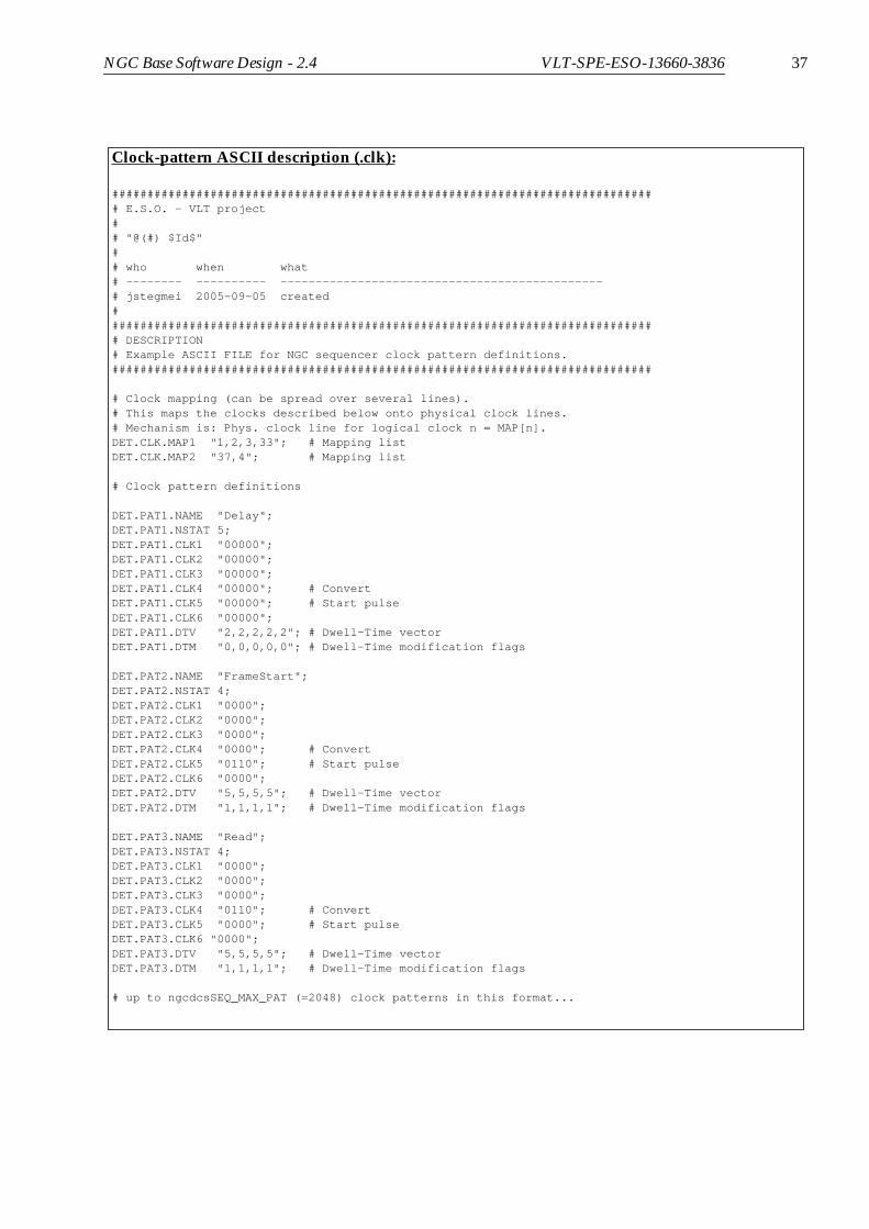
In the ASCII format described below the DET.PATi index directly gives the pattern reference indexto be used in the sequencer program ASCII description (see section 6.3.2). The uploading method al-ways has to take care of filling in the correct pattern address for each pattern object.
The clock-pattern description block may consist of up to 64 state-vectors (one for each bit in the se-quencer clock-pattern RAM). In order not to specify a huge number of unused clocks, a clock map-ping vector can be specified, which maps logical clocks described in the file onto physical clocklines. Clocks without map reference can also be addressed directly by their number (for example“DET.PATi.CLK62”).
Binary structured clock-pattern setup (.bclk):
# <Pattern-1>10b00000000000000000001000000000000 0b00000000000000000000000100000000 10b00000000000000000001000000000000 0b00000000000000000000000100000000 10b00000000000000000001000000000000 0b00000000000000000000000000000001 00b00000000000000000001000000000000 0b00000000000000000000000000000001 00b00000000000000000001000000000000 0b00000000000000000000000100000000 00b10000000000000000001000000000000 0b00000000000000000000000100000000 1!
# <Pattern-3>30b00000000000000000011000000000000 0b00000000000000000000000000000010 10b00000000000000000011000000000000 0b00000000000000000000000000000010 10b00000000000000000011000000000000 0b00000000000000000000000000000110 10b00000000000000000011000000000000 0b00000000000000000000000000000110 00b00000000000000000011000000000000 0b00000000000000000000000000000010 00b10000000000000000011000000000000 0b00000000000000000000000000000010 1!
# High Word | Low Word |Mod.-Flag
NGC Base Software Design - 2.4 VLT-SPE-ESO-13660-3836 37
Clock-pattern ASCII description (.clk):
############################################################################## E.S.O. - VLT project## "@(#) $Id$"## who when what# -------- ---------- ----------------------------------------------# jstegmei 2005-09-05 created############################################################################### DESCRIPTION# Example ASCII FILE for NGC sequencer clock pattern definitions.#############################################################################
# Clock mapping (can be spread over several lines).# This maps the clocks described below onto physical clock lines.# Mechanism is: Phys. clock line for logical clock n = MAP[n].DET.CLK.MAP1 "1,2,3,33"; # Mapping listDET.CLK.MAP2 "37,4"; # Mapping list
# Clock pattern definitions
DET.PAT1.NAME "Delay";DET.PAT1.NSTAT 5;DET.PAT1.CLK1 "00000";DET.PAT1.CLK2 "00000";DET.PAT1.CLK3 "00000";DET.PAT1.CLK4 "00000"; # ConvertDET.PAT1.CLK5 "00000"; # Start pulseDET.PAT1.CLK6 "00000";DET.PAT1.DTV "2,2,2,2,2"; # Dwell-Time vectorDET.PAT1.DTM "0,0,0,0,0"; # Dwell-Time modification flags
DET.PAT2.NAME "FrameStart";DET.PAT2.NSTAT 4;DET.PAT2.CLK1 "0000";DET.PAT2.CLK2 "0000";DET.PAT2.CLK3 "0000";DET.PAT2.CLK4 "0000"; # ConvertDET.PAT2.CLK5 "0110"; # Start pulseDET.PAT2.CLK6 "0000";DET.PAT2.DTV "5,5,5,5"; # Dwell-Time vectorDET.PAT2.DTM "1,1,1,1"; # Dwell-Time modification flags
DET.PAT3.NAME "Read";DET.PAT3.NSTAT 4;DET.PAT3.CLK1 "0000";DET.PAT3.CLK2 "0000";DET.PAT3.CLK3 "0000";DET.PAT3.CLK4 "0110"; # ConvertDET.PAT3.CLK5 "0000"; # Start pulseDET.PAT3.CLK6 "0000";DET.PAT3.DTV "5,5,5,5"; # Dwell-Time vectorDET.PAT3.DTM "1,1,1,1"; # Dwell-Time modification flags
# up to ngcdcsSEQ_MAX_PAT (=2048) clock patterns in this format...

38 NGC Base Software Design - 2.4 VLT-SPE-ESO-13660-3836
Three cases may arise when configuring the sequencer clock-patterns in the way described above:
6.3.2 Sequencer Program
The sequencer program may depend on an application specific set of parameters (like detector inte-gration time, number of samples, window parameters...), which at runtime are only known to thedetector control server. In the simplest case these parameters directly fit into the repetition countersof the LOOP and EXEC instructions:
Other applications may need to compute the repetition counters via arithmetic formulas:
ngcdcsSEQ CLASS
UploadASCII()UploadBin()
Editor
Tool_X
Tool_Y
test.clk
test_X.bclk
test_Y.y_out UploadFormat_Y()
ngcdcsSEQ_Y CLASS
ngcdcsSEQ CLASS
UploadASCII()UploadBin()
ngcdcsSEQ CLASS
UploadASCII()UploadBin()
a)
b)
c)
LOOP $DET.NREADSEXEC <1_second_delay_pattern> $DET.EXPTIMEEXEC <readout_pattern> 1
END
N = $DET.NREADS * $DET.NCYCLES;
LOOP $NEXEC <1_second_delay_pattern> $DET.EXPTIMEEXEC <readout_pattern> 1
END

NGC Base Software Design - 2.4 VLT-SPE-ESO-13660-3836 39
The detector readout will typically not consist of a single pattern, but of another piece of sequencerprogram code which is assembled in a sub-routine:
The next level of complexity is reached, when the computed parameters depend on the executiontime of such a sub-routine:
The arithmetic formulas may use conditional instructions to compute results depending on the set-ting of logical parameters. It is also required that some of the computed parameters are passed backto the server. For example the “actual” exposure time or the “minimum” detector integration timecan only be determined within this programming context, as arbitrary constant delays may be add-ed such as chopper transition time or fixed delays after detector reset.
The evaluation of arithmetic formulas at run-time should be implemented via a simple scriptinglanguage. As the script evaluation may need to be done frequently, the startup-overhead of thescript must be as short as possible. For the current implementation the TCL scripting language hasbeen chosen, as this is the current VLT software standard and the startup overhead is very short.The script evaluation may not be required by all applications. In particular this is a main differencebetween optical and infrared applications. Where no script is required a simple parsing can bedone. To optimize for both needs, a hybrid sequencer program format is used. The script evaluationbetween the SCRIPT/SCRIPT_END instructions can simply be skipped (as in the test1.seq exam-ple).
The clock patterns given as argument to an EXEC instruction are referred to by their reference in-dex. The mapping to their actual clock pattern RAM address is done internally by the uploading
N = $DET.NREADS * $DET.NCYCLES;NX1 = $DET.NX / $DET.NCHANNELS
LOOP $NEXEC <1_second_delay_pattern_1s> $DET.EXPTIMEJSR <readout>
ENDRETUIRN
<readout>:LOOP $DET.NY
EXEC <line_start_pattern> 1EXEC <sample_pattern> $NX1
ENDRETURN
N = $DET.NREADS * $DET.NCYCLES;NX1 = $DET.NX / $DET.NCHANNELS;T_DELAY = (($DET.EXPTIME / $N) - Time(<readout>)) * 10.0e9
LOOP $NEXEC <10_nanosecond_delay_pattern> $T_DELAYJSR <readout>
ENDRETURN
<readout>:LOOP $DET.NY
EXEC <line_start_pattern> 1EXEC <sample_pattern> $NX1
ENDRETURN

40 NGC Base Software Design - 2.4 VLT-SPE-ESO-13660-3836
method of the clock pattern configuration (see section 6.3.1).
The parameters defined via the USE statements, the execution times of the subroutines defined viathe SUBRT statements and the script code itself are passed to the script interpreter through stdin.Once the script code had been executed the (possibly updated) parameters are passed back throughstdout. The potentially used parameters are stored in an instance of the ngcbPARAM_LIST class (seesection 6.2). The list is passed to the ngcdcsSEQ class via the constructor. The ngcdcsSEQ class takescare for attaching its own instance to the ctrlList of all parameters which are declared in the USEstatement. The parameter list is intended to be maintained in a control server using instances of thengcdcsSEQ class for sequencer control. The list helps the server to optimize the frequency of se-quencer program re-loads.
So finally the sequencer program consists of three parts: the declaration section, the evaluation sec-tion and the actual program code. The declaration section contains the assignment of pattern names
PAT_A = 1PAT_B = 2PAT_C = 3
USE PARAM1 PARAM2USE PARAM3 PARAM4
SUBRT routine1 routine2
SCRIPTif {$svar(PARAM4)} {set svar(new1) [expr{$svar(PARAM1)*
($time_r(routine1) +$time_r(routine2))}]
} else {set svar(new1) [expr{$svar(PARAM1)*
$time_p(PAT_A)}]}SCRIPT_END
EXEC PAT_A $PARAM1LOOP INFINITE JSR routine1 3 LOOP $PARAM2 LOOP $new1 EXEC PAT_B END END
JSR routine2ENDEXEC PAT_A 1RETURN
routine1:LOOP $PARAM3 EXEC PAT_C 4ENDRETURN
routine2:INCLUDE "test1.seq"
test1.seq:
PAT_D = 4PAT_E = 5PAT_F = 6
EXEC PAT_DLOOP 10 JSR myRoutine1 LOOP 5 EXEC PAT_E 4 ENDENDRETURN
myRoutine1:LOOP 3 EXEC PAT_F 10ENDRETURN
Sequencer program ASCII description:

NGC Base Software Design - 2.4 VLT-SPE-ESO-13660-3836 41
to pattern numbers, the declaration of the used parameters and the declaration of subroutines. Nor-mally subroutines need not to be declared. The SUBRT statement is only required in case the execu-tion time of such a subroutine is needed in the evaluation section. The same applies to theparameter list. Parameters which are not used in the script but which are directly referred in theprogram code also need not to be declared. The evaluation section is enclosed with SCRIPT/SCRIPT_END statement. The whole section can be skipped if it is not required. The evaluation sec-tion is directly followed by the actual program code. Subroutines have to be labeled by a routinename. The label is just the name followed by ‘:’. The loop repetition factors can be either a hardcod-ed decimal value, the value of a parameter or INFINITE. A loop repetition factor evaluated to -1 isthe same as INFINITE, other negative values are illegal. The EXEC instruction is followed by twoarguments: the pattern number and also a repetition factor. Both can be hardcoded decimal valuesor the values of a parameter. A repetition factor of 1 may be omitted. The pattern number can be re-placed by its name when a name was assigned in the declaration section.
Declaration Section
<pattern_name 1> = <pattern_number 1><pattern_name 2> = <pattern_number 2>...<pattern_name N> = <pattern_number N>
USE <parameter_name 1> <parameter_name 2> ... <parameter_name N>USE ...
SUBRT <routine_name 1> <routine_name 2> ... <routine_name N>SUBRT ...
Evaluation Section
SCRIPT[SETLIB {myTclLib1 myTclLib2 ...}] # optional, can be used to embed own tcl-libraries[Script Code]# parameters are in $svar(parameter name)# subroutine execution times (milliseconds) are in $time_r(routine_name)# pattern execution times (milliseconds) are in $time_p(pattern_name)...SCRIPT_END
Program Code
# Nested LoopsLOOP <INFINITE|repetition_factor|$parameter_name> [LOOP... ...END] END
# Repeated Pattern ExecutionEXEC <pattern_name|pattern_number|$paramater_name> <repetition_factor|$parameter_name>
# Jump to SubroutineJSR <routine_name> <repetition factor>
# Include another program file to this positionINCLUDE <file_name>
# Subroutine Label (Routine Name)<routine_name>:
# Return from Main Program or from SubroutineRETURN

42 NGC Base Software Design - 2.4 VLT-SPE-ESO-13660-3836
The JSR statement jumps to a subroutine given by its name. It may optionally be followed by a rep-etition factor for repetitive calling of for example a “DELAY”-subroutine. The RETURN statementreturns from a subroutine to the position from where the subroutine has been called. A RETURNstatement in the main code (top level) will return from the whole program (exit).
The range of the counters of a LOOP construct is 16 bit integer [0, 65535]. The range of the “direct”repetition factors of the EXEC and JSR instructions is 32-bit signed integer [0, 2147483647], as the di-rect repetition factors are expanded internally to LOOP constructs.
This parameter driven program structure allows a wide range of application specific detector read-outs (multiple configurable windows/regions of interest, configurable pixel sub-sampling, etc.).
For completeness the sequencer module also contains a simple uploading method for a binary se-quencer program RAM description. Because of the required server interaction at run-time the appli-cable range of this fixed format is limited.
A local copy of the sequencer program RAM can be accessed directly through the public data mem-ber
ngcdcs_seqp_t program;
which contains the following members:
int code[ngcbSEQ_RAM_SIZE]; - sequencer program codeint length; - program code lengthngcdcs_subrt_t subRt[ngcdcsSEQ_MAX_SUBRT];- subroutinesint numSubRt; - number of subroutinesint stored; - program stored in controller
Binary structured sequencer program (.bseq):
0x4000 # start address for this piece of code0b000100000000000000000000000000010b01000000000000000000000000000001
0b000100000010000000000000000000010b001000000000000000000000010000000b000100001100000000000000000000010b000100000110000000000000000000010b00110000000000000000000000000001
0b000100000100000000000000000000010b001000000000000000000000010000000b000100001110000000000000000000010b000100001010000000000000010000000b000100010000000000000000000000010b000100001000000000000000010000000b00110000000000000000000000000001
0b001000000000000000000000000010100b000100000000000000000000000010100b00110000000000000000000000000001
0b000100000100000000000000000000010b001000000000000000000000010000000b000100001110000000000000000000010b000100001010000000000000010000000b000100010000000000000000000000010b000100001000000000000000010000000b00110000000000000000000000000001
0b00110000000000000000000000000001 !

NGC Base Software Design - 2.4 VLT-SPE-ESO-13660-3836 43
The ngcdcs_subrt_t object contains the following members:
int addr; - start address (relative to RAM base)int index; - reference indexint length; - subroutine code lengthdouble time; - execution time in secondschar name[128]; - subroutine name (optional)
It is possible to modify the global program structure directly and then upload it via a SetupPrg()method. The SetPrg(prg) method uploads an externally defined program and upon success the glo-bal program structure would be a mirror of what has been loaded. The code may completely residein the main program code without having the subroutines resolved (numSubRt = 0). Otherwise thesubroutines are placed at the given addresses. Convenience methods are available for checking andoptimizing the code (CheckPrg(&prg)) and for calculating code execution times (ExecTime(code,size)).The execution time calculation requires that the referred clock patterns have been uploaded before.
The program stored in the sequencer program RAM can be read back via a GetPrg(&prg) method.The DumpPrg(text, prg) member function dumps the binary program code to a formatted ASCII textof type (char *). The function automatically resolves subroutines and also calculates their execu-tion times.
6.3.3 Sequencer Control
The sequencer can be started and stopped via the Start()/Stop() methods. The Start() method has aparameter, which defines whether to raise the synchronous start signal or whether to start only thisinstance (see section 2.6). A sequencer instance only goes to running state in case a sequencer pro-gram has been loaded before. The synchronous start can be enabled or disabled with the RunCtrl()method. The Stop() method will interrupt the program immediately. Sometimes it is required tostop the pattern sequence only on dedicated break points. The break points are set in a bit in thehigh RAM word of a clock-pattern state. The Break() method will instruct the sequencer to stop atthe next break point. The Wait() method will wait with a given timeout until the program has termi-nated. A proper value for the timeout can be computed with a BreakTimeout() function, which willalso cover the case that the timeout may be infinite (no break point in the program) and only theStop() method can be used.
6.3.4 Synchronization
The synchronization mechanism with external events is described in section 2.7. It is fully undercontrol of the respective clock pattern design. The TriggerMode() function can be used to enable ordisable the “wait-for-trigger” state.

44 NGC Base Software Design - 2.4 VLT-SPE-ESO-13660-3836
6.4 CLDC Module Class
The ngcdcsCLDC class provides all functions to setup the clock- and DC-bias voltages on a CLDCmodule. The clock- and bias voltage setup can accessed through the public data members
ngcdcs_clk_t *clk; - array of clock voltagesint numClk; - number of clock voltagesngcdcs_dc_t *dc; - array of bias voltagesint numDc; - number of bias voltagesdouble offsetClk; - global offset for clock voltagesdouble offsetDc; - global offset for bias voltages
The ngcdcs_dc_t object contains the following members:
double volt; - setup valuedouble range[2]; - rangedouble dacCorr; - DAC correction factordouble telCorr; - ADC correction factor for telemetryint dacChan; - DAC channelint telChan; - ADC channel for telemetrychar name[64]; - name of the bias voltage
The ngcdcs_clk_t object contains the following members:
ngcdcs_dc_t level[ngcdcsCLDC_DCLK]; - multi-level biases for each clock
The current hardware uses two-level clocks (ngcdcsCLDC_DCLK = 2).
An overall configuration of all voltages on the CLDC module can be done via the LoadCfgFile()method. The LoadCfgFile() method can be overloaded to support/test different kinds of setup files ifrequired. The LoadCfgFile() method is intended to fill the above structures. The Setup() method willupload the structures to the controller. The SaveCfgFile() method will save the current setup to a file.Also this method can be overloaded to create other formats than the default one. The default formatsupported by the ngcdcsCLDC class is a short FITS format as shown below. The SaveCfgFile() meth-od will keep all comments when saving a modified voltage setup to a file. The voltages can bechanged at run-time individually within their defined range. It is possible at any time to restore thedefault values as they were given in the voltage configuration file originally loaded.
All voltages including the two global offsets can be set individually via member function calls. Volt-age telemetry can be done at any time for one selected voltage. Two clock channels can be selectedvia the Monitor() method to be routed to the two clock-monitor outputs of the board. A calibrationmethod (Calibrate()) can be called to compensate offset voltage errors on the individual DAC chan-nels. The voltage output of the module can be enabled and disabled via the Enable()/Disable() meth-ods. The voltage conversion functions ConvertDac() and ConvertTel() for the DAC and for thetelemetry can be overloaded to cover the needs for board modifications for special applications.

NGC Base Software Design - 2.4 VLT-SPE-ESO-13660-3836 45
Voltage definition file (.v):
############################################################################## E.S.O. - VLT project## "@(#) $Id$"## who when what# -------- ---------- ----------------------------------------------# jstegmei 2005-10-05 created################################################################################ DESCRIPTION# NGC voltage file. The keywords have to be defined for all used# clock- and DC-voltages in the following format:## DET.CLDC.CLKHINMi - Name of high clock i (optional)# DET.CLDC.CLKHIi - Level of high clock i (mandatory)# DET.CLDC.CLKHIGNi - Gain factor (optional)# DET.CLDC.CLKHIRAi - Range of low clock i (mandatory)## DET.CLDC.CLKLONMi - Name of low clock i (optional)# DET.CLDC.CLKLOi - Level of low clock i (mandatory)# DET.CLDC.CLKLOGNi - Gain factor (optional)# DET.CLDC.CLKLORAi - Range of low clock i (mandatory)## DET.CLDC.DCNMi - Name of DC voltage i (optional)# DET.CLDC.DCi - Level of DC voltage i (mandatory)# DET.CLDC.DCGNi - Gain factor (optional)# DET.CLDC.DCRAi - Range for DC voltage i (mandatory)##############################################################################
# Offsets:DET.CLDC.CLKOFF 10.0; # Global clock voltage offsetDET.CLDC.DCOFF 10.0; # Global DC voltage offset
# Clock Voltages:DET.CLDC.CLKHINM1 "clk1Hi";DET.CLDC.CLKHI1 3.000;DET.CLDC.CLKHIGN1 1.000;DET.CLDC.CLKHIRA1 "[-9.000, 9.000]";
DET.CLDC.CLKLONM1 "clk1Lo";DET.CLDC.CLKLO1 0.000;DET.CLDC.CLKLOGN1 1.000;DET.CLDC.CLKLORA1 "[-9.000, 9.000]";
# up to 16 clock voltages like this ...
# DC Voltages:DET.CLDC.DCNM1 "DC1";DET.CLDC.DC1 0.000;DET.CLDC.DCGN1 1.0;DET.CLDC.DCRA1 "[-9.000, 9.000]";
# up to 20 DC-voltages like this ...

46 NGC Base Software Design - 2.4 VLT-SPE-ESO-13660-3836
6.5 ADC Module Class
The ngcdcsADC class provides all functions to setup an ADC module. This class only contains somesetup functionalities to enable/disable ADCs on the board, to select a channel to be routed to thevideo-monitor output of the board and to switch between the several available operation- and simu-lation-modes. No separate configuration/setup file is required here, as the module configuration(i.e. the number of enabled ADCs) is done within the scope of an overall system configuration (i.e.where the boards, device names, routes and number of modules are defined). This overall systemconfiguration is outside the scope of this document, as there are huge differences between opticaland infrared applications.
6.6 Selftest
All hardware module classes provide a Selftest() method testing the hardware functionality to thepossible extend. The Selftest() method provides proper feed-back via the verbose-output and the log-ging system (see section 3.5).
6.7 Configuration Modules
All configuration files for the NGC hardware modules (clock pattern definitions, sequencer pro-grams, voltage configuration files) are intended to be stored in instrument- or detector-specific con-figuration modules, which are under CMM configuration control. This also applies to maintenanceand test configurations. Usually the configuration files are part of the NGC-system delivery. In caseswhere detector development is done outside, the respective instrumentation team is responsible forthe development of the configuration files. Templates and a graphical editing tool for the clock pat-terns will be provided.

NGC Base Software Design - 2.4 VLT-SPE-ESO-13660-3836 47
7 DATA PRE-PROCESSING
7.1 Concept
Basically the pre-processing task to be performed is:
• Receive data from an external device. Generally this is achieved by writing the data from thedevice directly to the computer memory (DMA) and generating an interrupt once a certainamount of data had been transferred (data event). The data flow is continuous.
• Compute a data-array containing the result of the pre-processing - in the easiest case by sortingand/or adding up several subsequent input arrays. The computation (“adding-up”, “sorting”)must happen in parallel to the reception (DMA) of the next input data array. The algorithmsare manifold and need specific parameters to be defined at run-time (“number of input arraysto add up”,...). There are no strict real-time requirements (i.e. guaranteed response time on adata event), but the amount of data to be processed within a certain time-slot is huge (up toseveral hundred Mega-Bytes).
• Transfer the result array to disk and/or to a display. The target disk and the display utilityusually reside on another computer (instrument workstation). Thus the transfer is done via anetwork interface. The transfer of the result array must also happen in parallel to bothreceiving and processing the next incoming data arrays (continuous data flow). Memorycopies have to be avoided.
The CPU speed and the bandwidth of peripheral buses on modern “standard” computers is in-creasing steadily. The usage of an “off the shelve” computer plus operating system gives the oppor-tunity to benefit from the rapid progress on the computer market and the wide range of availabledevelopment and debugging tools in combination with the least possible expense for portability is-sues. The following sections describe how the described data acquisition task can be performed onstandard computers running a UNIX/Linux operating system as it is delivered with the ESOVLTSW releases.
7.1.1 Parallel Computing Architecture
In order to improve the computing bandwidth, modern computers can be equipped with severalCPUs. When a process becomes runnable, the scheduler looks, which CPU is the least busy, andthen grants this CPU to the process. Once a process is running on a certain CPU, it will keep thisCPU until it is re-scheduled. Re-scheduling may occur either after a certain time-slot (in case otherprocesses are also runnable) or when the process has to wait (for example for a semaphore or for in-put on a socket). When processing large data arrays, the computing task has to be distributed acrossseveral processes to benefit from the multi-CPU architecture. In the simplest case with two CPUswe would execute two processes, where one was processing the first half of the array while the oth-er was processing the second half. The operating system always takes care of the optimal CPUwhere to schedule a process. Once process-1 is scheduled on CPU1, the process-2 will automaticallybe scheduled on CPU2 (as now this is the least busy) without doing any further pre-selection. Thisscheme will work unless there are no other processes with high CPU-needs running on the NGC-LCU (see section 7.1.2 about how to avoid unwanted scheduling if this was the case). The two pro-cesses have to be synchronized (i.e. they have both to be triggered when a new data-array is avail-able for processing). This master task requires at least one more process. Once the processing is

48 NGC Base Software Design - 2.4 VLT-SPE-ESO-13660-3836
done, the result still has to be transferred to give space for the next incoming data. The transfer ofthe result data (to disk or to another computer) also has to be done in parallel to the processing ofthe next set of input data and therefore also requires a separate process. Finally both data-processingand data-transfer need some external input (commands) to be controlled (START, STOP) and to beparametrized (SETUP). This command handling must react asynchronously at any time and is thefifth process in our minimum configuration:
Figure 11 Parallel Data Processing
7.1.2 Priority Controlled Scheduling
By default the UNIX model grants certain time-slots to each process to guarantee a fair distributionof the computing resources. When the data processing approaches the limit of the CPUs bandwidth,a priority scheme has to be assigned in order to avoid, that less important tasks interrupt the time-critical tasks. For example the data transfer should just be done, when there is enough time to trans-fer. In case the processing task adds up 10 data arrays to compute their average, the transfer task hasthe time of 10 data events to transfer the average until the next result is available. In case of normaltime-sharing scheduling the transfer-task would immediately start running after the 10th array hadbeen processed and would compete with the processing-task for CPU-resources, where both wouldbe granted the same amount of CPU-power. This would result in a possible loss of input data, incase the CPU-load of the processing task was more than 50%.
Figure 12 Non-priority-based scheduling
One possibility was to install as much physical CPUs as there are processes needed for the acquisi-tion. For more complex processing tasks, requiring more than 2 processes (for example non-destruc-tive read-out or computation of standard deviation), this would become expensive and would alsonot put all of the CPUs to effective use (for the lower priority tasks). A better way to use the fullcomputing bandwidth of all installed CPUs is to assign a priority scheme to the processes:
ProcessData 1
ProcessData 2
Capture
TransferTask
CommandHandler
MemoryComputer
Data Event (device driver signals, that
Command/Reply
Trigger
Wait
TriggerWait
Trigger
Wait
the data has been written to the computer’smemory)
Result-Data
(START/STOP/SETUP)
Processing-Task
Transfer-Task
crash (no time left to handle next data event)

NGC Base Software Design - 2.4 VLT-SPE-ESO-13660-3836 49
Figure 13 Priority-based scheduling
The Linux operating system provides a soft real-time scheduling technique, which allows to runprocesses with distinct priorities. The priority setting however requires super-user privileges. The“sudo” command or a dedicated installation user with the appropriate access rights may be chosento overcome installation caveats.
The priority scheme introduces a further level of complexity into our process model, but gives morecontrol over the scheduling. Of course we want at least to be able to stop the system at any time.This implies, that the command handling process has the highest priority in the system. The secondpriority is given to the capture process, as this has to react in time to the data events. The next prior-ity level is given to the tasks processing the raw data arrays. All other tasks have a low prioritysharing the remaining bandwidth.
Although this is not yet a full “real-time” system, the priority scheme guarantees a stable mean-pro-cessing time which is sufficient for all image pre-processing done outside the very fast control loops(e.g. as needed for adaptive optics). Jitters in the response time (latency) which are in the range ofseveral milliseconds can be overcome by implementing a ring-buffer of an appropriate size for theincoming data.
The system interfaces to the outside world via two processes: the command handler and the trans-fer task. The processing task is supposed to deliver different types of result-data (raw frames, aver-aged frames, standard deviation,...). This means, that the receiving process has to decide, whichdata it is interested in and so the transfer-task will transfer data only upon request. Although the re-quest has the nature of a command,. it should not be handled by the command-handler, because inthis case it would be handled with the highest priority. As this is just what we intended to avoid, asecond “command handling” has to be implemented within the transfer task itself. The receivingprocess can then start/stop/setup the system via a command sent to the command handler, butwill send data requests directly to the transfer task, which then only handles this request whenthere is time to do so (the computed result data arrays will be queued up to a configurable size):
Figure 14 Data Transfer/Command Handling
Processing-Task
Transfer-Task
Receiver
CommandHandler
TransferTask
Start/Stop/Setup
Reply
Request
Data
50 NGC Base Software Design - 2.4 VLT-SPE-ESO-13660-3836
7.1.3 The Threads-Model
Although the UNIX process model together with the IPC mechanisms is sufficient for parallelizingthe data acquisition, this is still heavy to handle, as all global variables have to reside in a sharedmemory area, where the applications must take care to allocate and free space for all kinds of globaldata structures. Furthermore the cleanup of this stuff after a process crash is a complex job for itself.Linux, SUN Solaris and all POSIX-standard compliant UNIX releases support a programmatic inter-face, which hides all of this implementation details from the programmer. This mechanism is calledmulti-threading. A thread is in its functionality the same as a process. The difference is just, that threadscan run within one address space and can therefore use the same memory and global variables. Amain-thread is started like a process and then it starts in turn other threads for executing different jobsin parallel on the same data. The threads model also includes several internal task-synchronizationfeatures (mutexes, conditions, counting semaphores) which help to make the task-control more easyto survey. Like a process a thread can also be executed with a distinct priority.
Multi-threading gives a clear performance improvement. A process has five fundamental parts: code(“text”), data, stack, file I/O, and signal tables. Processes have a significant amount of overheadwhen switching: All the tables have to be flushed from the processor for each task switch. If a processspawns a child process using fork(), the only part that is shared is the text. Threads reduce this over-head by sharing the fundamental parts. Due to this mechanism switching happens much more fre-quently and efficiently, which is essential for our parallel data acquisition task.
The usage of global data among several threads requires mutual exclusion mechanisms in order toprevent, that for example the same variable is read and written at the same time or incremented/decremented at the same time. A routine which takes care of this is called “thread-safe”. Thread safe-ty can be achieved by protecting global variables and also the execution of code fragments with mu-texes or semaphores. In many cases the mutual exclusion is just inherent in the functionality and canbe achieved by designing a proper task distribution.
Multi-threading is supported by Linux, SUN Solaris and all POSIX-standard compliant UNIX re-leases. Applications based on this mechanism can very easily be ported to all of these operating sys-tems. For simulation purposes the same acquisition process code may run on all developmentcomputers. Together with the priority based scheduling feature the system balances itself makingmaximum use of any number of CPUs installed. The same program, that at high data-rates wouldspread itself across all available CPUs, can also run on a cheap single-CPU architecture, when onlylow input data rates are expected. The whole data acquisition task can directly be started in one stepfrom a UNIX/Linux command shell without requiring any further startup-script and process moni-toring.
7.2 The Acquisition Process
The acquisition processes can be started as individual tasks on the NGC-LCU (in simulation modealso on the instrument workstation). The incoming data are read via DMA into a ringbuffer. Thecapture process provides the synchronization between the DMA-driver and the calculation process.A ringbuffer overflow is also detected by the capture process. After processing the data, the resultframe will also be stored in a ringbuffer to guarantee continuous data flow. Any data transfer is ful-ly parallel to the processing loop (i.e. while transferring the result, the next result is computed).There are no memory copies required. When the frame has been processed and should be trans-ferred, it is given to the data server. From here the frames can be distributed in parallel to severalhosts via parallel data transfer threads. The frames are transferred on request. The request may beFIFO (for science data transfer) or LIFO (for video data transfer). Different frame types can be trans-ferred in parallel to different requesting data clients (i.e. the display shows raw frames while the av-eraged frame is transferred and stored to a FITS-file). Using this method the transfer capacity is only

NGC Base Software Design - 2.4 VLT-SPE-ESO-13660-3836 51
limited by the network bandwidth and the computing power of the requesting client process. It ispossible to download data sets like flatfields or bad-pixel masks. The data sets can be stored inshared memory to be shared between acquisition processes. This acquisition process frameworkprovides a flexible mean to implement any kind of “on the fly” pre-processing (bias subtraction,fast centroiding, digital filtering, handling of chopping and/or nodding cycles, etc.).
If the ‘-i’ option is not specified, the acquisition process starts the data capture and processing itself,using the default parameter setting (auto-start). This mode is reserved for test purposes. For using acommand interface the acquisition process has to be invoked with the ‘-i’ option. Most acquisitionprocesses additionally support the command line options ‘-nx <n>’ and ‘-ny <n>’ from where theyderive the DMA size and the dimension of the produced data frames.
7.2.1 Initialization
The basic initialization of the DMA system is done via the ngcppStartup() function.
ngcppStartup(argc, argv, size, erms)
The command line arguments (argc, argv) of the process have to be passed to this routine, so thatsome default stuff (such as device names) can be evaluated. The third argument defines the size (inbytes) of one DMA ringbuffer element. The DMA size can be redefined within the scope of the ac-quisition loop if required (see section 7.2.4), but only in case the DMA is stopped at that time.
7.2.2 Exporting Parameters
The acquisition process may need to be controlled through an arbitrary number of application spe-cific parameters. These parameters need to be made public in order to be able to set them “byname” through the command interface. A parameter structure myTYPE and an associated array ofparameter names have to be defined by the application. Afterwards the dynamic parameter struc-ture has to be passed to the system. This is done via the ngcppSetupDynParam() function. Then somedefault parameter values have to be set. The ngcppParamDefault() function informs the system, thatthe default parameter setup has been done. Now the command handler is able to receive a doublebuffered mirror of all parameters defined in myTYPE:
Usage: ngcppXXX [options] Options: -i enable interactive mode -im <input mode> input mode (normal, sim) (default: normal) -cmdport <portNum> set command server port (default: 0) -dataport <portnum> set data server port (default: 0) -nclient <numClient> max. number of data clients (default: numClient = 0) -dev <n> <device> device name for device <n> (default: /dev/ngc0_dma (device 0)) -st <time> simulation interval time in ms (default: simulation time = 500 ms) -v switch verbose mode on -h show this

52 NGC Base Software Design - 2.4 VLT-SPE-ESO-13660-3836
7.2.3 Frame Types
A data frame consists of a frame header and an output ringbuffer. With each frame a certain frametype (DIT, INT, STDEV...) and a data type (integer, floating point,...) are associated. There are de-fault frame types defined within the ngcpp module:
ngcppFRAME_SNAPSHOT - snapshot framengcppFRAME_DIT - DIT-framengcppFRAME_INT - INT-framengcppFRAME_INTERMEDIATE_DIT - intermediate DIT-framengcppFRAME_INTERMEDIATE_INT - intermediate INT-framengcppFRAME_SDV - standard-deviation framengcppFRAME_SAMPLE - sample framengcppFRAME_HCYCLE1 - first half-cycle framengcppFRAME_HCYCLE2 - second half-cycle framengcppFRAME_TRACK - vector for offset corrections
It is also possible to add new frame types to the system. The frame type has to be a single bit value.The least significant bits are used for the pre-defined default frames. The first unused bit can be re-trieved by defining myFRAME_TYPE in the following way:
#define myFRAME_TYPE (ngcppFRAME_USER << 1)
To introduce a new frame type to the system, one has also to specify a frame name and a parametername (both ASCII-strings). If the parameter string is not empty, the specified parameter should beused to switch the generation of the frame on/off:
ngcppAddFrameType(myFRAME_TYPE, “MYFRAME”, “DET.NC.MYFRAME”, erms)
Each frame has to be at least double-buffered. Science-frames (like the INT-frame), which have to bestored in any case should have three ringbuffer elements (this depends on the expected computationrate of the frame and the transfer time including storage on disk). The output ringbuffer has to be al-
static char *names[] = {“DET.MYFRAME”, “DET.MYPARAM1”, “DET.MYPARAM2%f”, “DET.SETUPID”};typedef struct{ int myFrame; int myParam1; float myParam2; int setupId;} myTYPE;
param = (myTYPE *)ngcppSetupDynParam(_vecsize(names), (char **)names, 0, erms))
/* Set default parameter values */param->setupId = 0;param->myFrame = 1;param->myParam1 = 0;param->myParam2 = 1.5;ngcppParamDefault();

NGC Base Software Design - 2.4 VLT-SPE-ESO-13660-3836 53
located by the acquisition process. Then the frame has to be passed to the system:
The ringbuffer element, that has to be used for processing the frame, is assigned by the system andis always stored in the structure element myFrame.dptr. So all processing has to be done on resMy-Frame[myFrame.dptr].
7.2.4 Acquisition Loop
After the initialization phase, the acquisition process has to wait for the start command with ngcpp-WaitStart(). After receiving the start command, it can do some further initialization steps (such asredefining the DMA size) and will then signal to the capture process, that the main process is nowready to get data. The ngcppStartCapture() function will enter the DMA-loop. From now on all fur-ther processing has to keep up with the incoming data flow. So the acquisition process should enterthe acquisition loop immediately. With ngcppWaitData() it waits for the next data buffer, processesit and finally calls the acknowledge-function ngcppAckData(), when no more processing has to bedone with the current data buffer.
static int *resMyFrame[2]; /* data-ring buffer of my-frame */static ngcppFRAME myFrame; /* frame structure for my-frame */int numPix = nx * ny;
/* Allocate frame buffers */for (i=0;i<2;i++) { resMyFrame[i]=(int *)malloc (numPix * sizeof(int)); }
/* Initialize frame structures */myFrame.h.start_x = 0;myFrame.h.start_y = 0;myFrame.h.nx = nx;myFrame.h.ny = ny;myFrame.h.dtype = ngcppDTYPE_INT32;myFrame.h.ftype = myFRAME_TYPE;ngcppInitFrame(&myFrame, (char **)resMyFrame, 2);

54 NGC Base Software Design - 2.4 VLT-SPE-ESO-13660-3836
7.2.5 Data Transfer
To transfer a data frame an output request function has to be called:
myFrame.h.setupId = param->setupId; ngcppReqOut(ngcppQUEUE_SKIP, &myFrame);
The setupId header element is used by the receiving process to identify frames belonging to a certainparameter setup. This is needed, as parameters may change, while the system is running.
The first argument of the ngcppReqOut() function is used to specify the behavior, when the outputringbuffer of the frame is full. It has to be one of the following values:
ngcppQUEUE_SKIP - skip frame, if queue is fullngcppQUEUE_BLOCK - block until queue is freengcppQUEUE_SETERR - set an error flag in the frame header and skip
7.2.6 Importing Data-Sets
The acquisition process has the possibility to reserve memory that can be filled from remote via the
/* Main loop */while(1) { active = 1;
/* Wait for start */ if (ngcppWaitStart() == -1) continue;
/* Some initialization if required (redefine DMA size, ...) */
/* Signal capture process, that process is ready to get data */ if (ngcppStartCapture() < 0) continue;
/* Acquisition loop */ while (active) { /* Get next data buffer */ ngcppWaitData(dataIn);
/* Check, if stop signal has been received */ if (!(active = ngcppCheckStop())) continue;
/* Now process the data somehow */
/* Transfer computed data frames */
/* Let capture process know, that data has been processed */ ngcppAckData(); } /* end of acquisition loop */
/* Terminate processing */ ngcppTermProcessing(); ngcppFlushOutput(); } /* end of main loop */

NGC Base Software Design - 2.4 VLT-SPE-ESO-13660-3836 55
command handler. This memory area(s) may contain flatfield(s), badpixel-mask(s) or other datasets used for the pre-processing (or also the simulation) of image data. The buffer can be set fromthe controlling process via the ngcppUploadBuf() function. As the reserved memory is double buff-ered, the acquisition process would not block while an upload is in progress. Once all buffers areset, a synchronization command ngcppMsync() has to be sent to the command handler to performthe buffer swap. The memory areas can be placed in shared memory in order to be shared betweendifferent acquisition processes.
7.2.7 Pixel Sorting
The structures of the detector arrays differ a lot. Ordering can be in stripes, quadrants, quadrantsand stripes, from outside to inside or vice versa. The sorting and processing of the arrays mightmake the parallel computation algorithms quite complex. For very large arrays, which do no morefit into the cache, the sorting might additionally slow down the performance of the real-time loop. Ifapplicable the frames can be computed as raw unsorted buffers, which are reformatted just beforethey are transferred. For this purpose a pixel map (ngcppPixMap) has to be defined. The ngcppPix-Map is declared as NULL pointer by default. It is only applied if it points to a valid map. The acqui-sition process can allocate an integer buffer with appropriate size and fill it with a sorting table.Then the ngcppPixMap must be set to the defined map:
ngcppPixMap = myMap;
The map will apply the following sorting:
out[i] = data[ngcppPixMap[i]];
The transfer task also takes care of window requests. If a special frame should be transferred un-sorted even though a pixel map has been defined, then the noSort flag must be set in the framestructure when passing it to the output queue:
myFrame.noSort = 1;ngcppReqOut (ngcppQUEUE_SKIP, &myFrame);
#define myDATA_SET_ID 4 /* has to be a single bit value */char *myDataSet;
ngcppShDataAttch(0, erms);ngcppShDataGetPtr((char **)&myDataSet, myDATA_SET_ID, size, erms);while (active) { ngcppWaitStart(); ngcppStartCapture(); while (started) { ngcppWaitData (&dataIn); if (ngcppShDataIsValid(myDATA_SET_ID) { /* process data frame: frame = f(dataIn, myDataSet) */ } ngcppAckData(); } ngcppTermProcessing(); }

56 NGC Base Software Design - 2.4 VLT-SPE-ESO-13660-3836
7.2.8 Run-Time Flags
There are two global flags for exposure control. They are set asynchronously via the command inter-preter task and can be checked at run-time within the acquisition loop. Both flags have to be reset bythe application after they have been checked.
The counter-reset flag (ngcppResetCnt) is set, when the exposure should (re-)start while the sequenc-er is left running (continuous mode). Typically at this point the observing conditions have changed(telescope move etc.). This means, that the DMA-input buffer has to be flushed ngcppFlushInput()and the current integration has to be skipped. This has to be taken into account when estimating theexposure time. In the worst case one integration is lost.
The exposure-end flag (ngcppEndFlg) is set, when the exposure should end immediately. Typicallynow an intermediate result should be transferred.
7.2.9 Simulation Mode
The acquisition process has a built-in simulator. In simulation mode the input-ringbuffer is pre-filled with default-data. The input sequence is simulated via timer functions (maximum resolution:1 ms, maximum frequency: 100 Hz input-frame rate). The content of the data can be explicitly set bydefining a function of type:
static void simul(short **buf, int size, int num, int *p)
This allows the application to fill the num ring-buffer elements with detector- and read-out mode-specific data. The size gives the number of 16 bit data-words in each ring-buffer element. The pointer“p” is reserved for future use.
Then the routine has to be assigned before the ngcppStartup() function is called:
ngcppSimBuf = simul;
If no buffer simulator is defined, a noise pattern will be used by default. It is also possible to uploadsimulation data using the import mechanism described in section 7.2.6. As in that case simulationdata for all produced frame types need to be uploaded, the applicable range of this feature is limit-ed.
7.3 Acquisition Process Interface
The previous sections have shown the principle of the acquisition process. Now we still have to pro-vide an interface to send commands to the process and to receive data from it.
7.3.1 Data Interface
The data frames can be requested in parallel from the data transfer threads. This is needed, as the ac-quisition process produces various different frame types and the frame type to be displayed (video-data) and the frame type(s) to be stored on disk (science-data) are not necessarily the same. Even ifthe user wants to get the same data both saved to disk and displayed in the RTD, then one still needsparallel channels for smooth operations not blocking each other. The saving to disk may take longerthan the display (or vice versa), the display may run anywhere else (on a dedicated host) and finallyone always wants to display the most recent image while when saving to disk one needs the oldestimage, which has not yet been saved. If required due to performance reasons, the video transfer

NGC Base Software Design - 2.4 VLT-SPE-ESO-13660-3836 57
(RTD) may be stopped while taking the science-data for an exposure.
The data transfer is done via socket (TCP/IP). The ngcppOpenDataLine() routine distinguishes be-tween the video- and the science-data transfer. In science mode the oldest available, but not yettransferred frame, which matches the frame-type in the request structure is transferred (FIFO). Invideo-mode for each frame-type matching the request, the latest not yet transferred frame is select-ed (LIFO). From this selection the oldest frame is transferred. In both cases ‘not yet transferred’means, that the frame has not yet been transferred to the requesting client. In video-mode addition-ally the retransmit flag in the request structure is checked, to allow frames of the specified type tobe transmitted again. This can be used, to display different windows of the same frame during longintegrations.
Format of the request structure:
typedef struct { int type; /* requested frame type */ int blocking; /* block until frame is ready */ int retransmit; /* transfer last buffer again */ int start_x; /* window start-x */ int start_y; /* window start-y */ int nx; /* window nx */ int ny; /* window ny */} ngcpp_req_t;
Format of the returned frame structure:
typedef struct { int dtype; /* data type */ int ftype; /* frame type */ int start_x; /* window start-x */ int start_y; /* window start-y */ int nx; /* window nx */ int ny; /* window ny */ int scal; /* scale factor */ int cnt; /* frame counter */ int setupId; /* setup-id */ int err; /* error code */ int overrun; /* overrun flag */ int frames; /* available frame types */ int tx; /* track point x */ int ty; /* track point y */ float expFactor; /* exposure time factor */ int reserved1; /* reserved */ int reserved2; /* reserved */ int reserved3; /* reserved */ int reserved4; /* reserved */ int reserved5; /* reserved */} ngcpp_hdr_t;

58 NGC Base Software Design - 2.4 VLT-SPE-ESO-13660-3836
The sequence for the function calls should be the following:
• ngcppPingDataLine() (optional);
• ngcppOpenDataLine(serverName, &socket,...);
• ngcppSendDataRequest(socket, request,...);
• ngcppWaitDataReply(socket, &frameHeader...);
• Check frame header. The frame name can be resolved with the ngcppGetFrameNameByType()function (optional);
• If frame type is ngcppFRAME_NO_FRAME, then send a new data request. Otherwise do eithertransfer the frame (the window parameters in the request may still be updated now) withngcppAcceptFrame(socket, request, &frame,...) or skip it with ngcppSkipFrame(socket,...);
• The frame can be scaled using the general ngcppScale(&frame) function (optional);
• Continue with ngcppSendDataRequest(socket, request);
The socket can be used for a select() call before ngcppWaitDataReply(). To cancel a request one has tocall ngcppCancelReq(socket, ...) before ngcppWaitDataReply() and then send a new request withngcppSendDataRequest().
If any of these functions fails, one should call ngcppCloseDataLine() and then try to reopen with ngcp-pOpenDataLine() to recover the data channel from failure.
The calling program should not exit with an open request. When the process is waiting for the datareply, ngcppAbortReq(serverName, pid,...) or ngcppCancelReq(socket,...) have to be called before exiting.It is recommended to add ngcppAbortReq() or ngcppCancelReq() to a signal handler.
The ngcppAcceptFrameN(socket, request, &frame, partNo, numDiv, ...) function can be used instead ofngcppAcceptData() to request a frame partition. The additional parameters partNo and numDiv haveto be supplied to indicate that the partition number partNo out of numDiv sub-divisions of the framehas to be taken as base for the requested window.
The described functions are sufficient to receive data from the acquisition process. They can be usedfor stand-alone applications (RTD-interface) or also for various test purposes. To get this interfaceinto the context as described in section 3.2, a more object oriented approach is needed. ThengcdcsACQ_DATA class will assemble the functions into an object, which can be configured eitherat creation time using the constructor or after creation using a Configure() method. The configura-tion is store in the following members of the ngcdcs_acq_cfg_t structure:
int dataPort; - data server portint transferMode; - data transfer modechar host[64]; - acquisition process host
Once configured a data connection can be established and closed with simple calls to the Open()/Close() member functions. Then data can be requested, transferred, skipped or re-transmitted in aflexible way using the class member functions. File descriptors and the request structure are storedinside the object and are transparent to the applications using the object.

NGC Base Software Design - 2.4 VLT-SPE-ESO-13660-3836 59
7.3.2 Data Export
The acquisition process framework allows the export of data buffers for external processing (for ex-ample with higher level image processing systems):
void ngcppDataExport(void *buffer, int ftype, int bitPix, int nx, int ny)
With the appropriate counter-part in the data interface to be included by the used tool:
ngcppSIMPLE_HDR *ngcppImportData(void **buffer, char *erms)int ngcppReturnData(char *erms)
The installation, startup and task management for these external tools is outside the scope of thisframework. Generally this mechanism may introduce huge performance drops depending on theinterface of the used tool. The usage of a dedicated acquisition process to perform a raw-data burstand an off-line processing with the respective tool should be taken into consideration before intro-ducing this further complexity.
7.3.3 The Acquisition Module Class
The ngcdcsACQ class provides all functions to execute/kill an acquisition process on the NGC-LCU. One instance of the ngcdcsACQ class has to be created to control one acquisition process. Theparameters exported by the process are attached to a global parameter list (ngcbPARAM_LIST, seesection 6.2), which is passed via the constructor. The class contains functions to maintain these pa-rameters, to upload data sets, to switch between normal mode and simulation mode, to start/stopthe acquisition and to set the run-time flags (see section 7.2.8) at the proper time. The acquisitionmodule also creates an instance of the ngcdcsACQ_DATA class in order to receive data from thelaunched process. The object is stored in the public member “data” of the ngcdcsACQ class. The con-figuration structure for the data interface is propagated from the more overall configuration of thengcdcsACQ class. So the complete ngcdcs_acq_cfg_t structure contains:
int cmdPort; - command server portint dataPort; - data server portint errPort; - error-stack server portint numDataClient; - number of data clients per processint transferMode; - data transfer modechar host[64]; - acquisition process hostchar dev[128]; - acquisition process DMA device nameint seqIdx; - associated sequencer instancechar name[64]; - optional name for this module
The data transfer done by the internal data object would block the acquisition module during thetransfer time of the image data. The applicable range of the data object would be limited unless oneprovides a mechanism for asynchronous data transfer. Without using such a mechanism the datatransfer should be done by an external data transfer task. The host name and the port number re-turned by the Host()/DataPort() member functions of the ngcdcsACQ class can be used to configuresuch a task. Even though this was a standard solution, it will become complex and heavy to admin-istrate in case of large mosaics with many acquisition processes on different NGC workstations. Touse the full transfer bandwidth one data transfer task per acquisition process needs to be launchedand controlled. A much more elegant way would be to use the internal data object from within athread running in the scope of the ngcdcsACQ class itself. This minimizes all configuration and syn-chronization effort, as all needed information is simply already there and needs not to be communi-cated at all. However the POSIX threads interface as described in section 7.1.3 basically does notallow to create a thread by using a pointer to a C++ class member function. The solution is to put

60 NGC Base Software Design - 2.4 VLT-SPE-ESO-13660-3836
the starter function outside of the class and declare it as extern "C". The POSIX thread creation rou-tine allows a (void *) argument to be passed to the starter function. This can be used to pass a point-er to the application class instance to the starter function, which then in turn can safely execute theproper member function. The ngcb module contains a C++ class (ngcbTHREAD) which implementsthis mechanism. By deriving from this ngcbTHREAD class it is possible to create/kill member func-tion threads easily via the new/delete operator:
myThread = new ngcbTHREAD(this, (ngcbPROCESS_T)&myClass::MyFunction, &myArg);...delete myThread;
For completeness the ngcbTHREAD library also contains a C++ style semaphore implementationwhere a (counting) semaphore can also be created and initialized with the new operator.
mySem = new ngcbSEM(count);mySem->Wait(); // decrement counter, block if zero...mySem->Post(); // increment counter
For pure mutual exclusion purposes a (faster) mechanism (binary semaphore) is also included:
mySem = new ngcbSEM(1);mySem->Lock(); // block, if locked...mySem->Unlock(); // release the lock
The acquisition module class derives from the ngcbTHREAD class and uses a (private) memberfunction to perform the asynchronous data transfer. The StartTransferring() method will launch thethread, the StopTransferring() method will abort it. The transfer thread will request the image(s) fromthe acquisition process, receive the image data and finally call a Store() method to save the data todisk. Some FITS-header information is created internally at run-time (such as actual image dimen-sion, frame type, data type and time stamps). Other FITS information (coming from a system snap-shot at exposure start) is passed to the ngcdcsACQ class from outside. The FITS information iscombined and stored at the right place within the Store() method depending on the selected file for-mat. The Store() method can be overloaded to implement different file formats. Using the threadmethod the ngcdcsACQ class can easily be set up through member function calls to receive any typeand any number of image frames from the acquisition process.
In order not to use the asynchronous data transfer the DataConnect() method should be overloadedwith an empty function. This would prevent the ngcdcsACQ instance from establishing an (unused)data connection when launching the acquisition process.
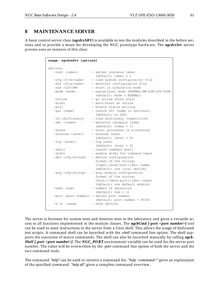
NGC Base Software Design - 2.4 VLT-SPE-ESO-13660-3836 61
8 MAINTENANCE SERVER
A basic control server class (ngcdcsSRV) is available to test the modules described in the before sec-tions and to provide a mean for developing the NGC prototype hardware. The ngcdcsSrv serverprocess uses an instance of this class:
The server is foreseen for system tests and detector tests in the laboratory and gives a versatile ac-cess to all functions implemented in the module classes. The ngcbCmd [-port <port number>] toolcan be used to send instructions to the server from a Unix shell. This allows the usage of dedicatedtest scripts. A command shell can be launched with the -shell command line option. The shell sup-ports the execution of macro commands. The shell can also be launched manually by calling ngcb-Shell [-port <port number>]. The NGC_PORT environment variable can be used for the server portnumber. The value will be overwritten by the -port command line option of both the server and thetwo command tools.
The command "help" can be used to retrieve a command list. "help <command>" gives an explanationof the specified command. "help all" gives a complete command overview.
usage: ngcdcsSrv [options]
options: -inst <label> - server instance label (default: label = ) -cfg <file-name> - load system configuration file -dcf <file-name> - detector configuration file -sim <LCU|HW> - start in simulation mode
-mode <mode> - operational mode (NORMAL|HW-SIM|LCU-SIM) (default: mode = NORMAL) -online - go online after start -start - auto-start at online -poll - enable status polling -gui [name] - launch GUI (name is optional) (default: no GUI) -ld <dictionary> - load dictionary (repetitive) -det <index> - detector category index (default: index = 1) -xterm - start processes in x-terminal -verbose <level> - verbose level (default: level = 0) -log <level> - log level (default: level = 0) -shell - launch command shell -stdin - enable stdin for command input -dev <cfg-string> - device configuration format of the string: [type]:[host|env]:[dev.-name] (default: one local device) -acq <cfg-string> - acq.-module configuration format of the string: [host]:[data-port]:[dev.-name] (default: one default module) -ndet <num> - number of detectors (default: num = 1) -port <port number> - server port number (default: port number = 8030) -h or -usage - show options

62 NGC Base Software Design - 2.4 VLT-SPE-ESO-13660-3836
The execution of this server does not require any special user privileges to be granted by the operat-ing system.
For software testing it is possible to emulate various errors:
• No acknowledge from hardware module (“no_ack”)
• Invalid address on a NGC hardware module (“ivld”)
• Sequencer FIFO empty (“seq_empty”)
• Sequencer goes to IDLE state (“seq_idle”)
• I/O error on all communication links (“io_err1,2,3”)
• I/O error on data link (“data_io”)
• Error when writing data to a file (“data_file”)
• Server blocks forever (“block”)
Others may be added. The emulation can be done with the command “simerr <identifier>”.

NGC Base Software Design - 2.4 VLT-SPE-ESO-13660-3836 1
1 TRACEABILITY MATRIX
1.1 NGC Requirements from [AD6]
Item Requirement Section
3.7 Software
1 Generally, software shall not limit the performance of the hard-ware.
6.1, 7
2 It shall be command driven. 5.1, 5.2, 8 (to a limitedextend)
3.7.1 High-level operating systems
3 The high-level operating systems must be |compliant with theVLT requirements. However, their number and diversity shall bekept to the minimum necessary for NGC.
2.2
4 A careful attempt shall be made to define an interface layerbetween the NGC control software proper and the operating sys-tem(s) and so to enable porting of all software above this layer atreasonable cost.
3.1, 4.4
3.7.2 Configuration Control
5 At all times, all software and all parameter files shall be keptunder configuration control.
3.2, 6.7
6 For critical parameter files, an additional mechanism to ensuretheir integrity (e.g., check sums) should be considered
TBD
3.7.3 Programming
7 The usage of modern code-generating tools with a view towardstesting, documenting, and debugging is encouraged. Their selec-tion should be coordinated with the Technical Division. Islandsolutions should be avoided.
TBD
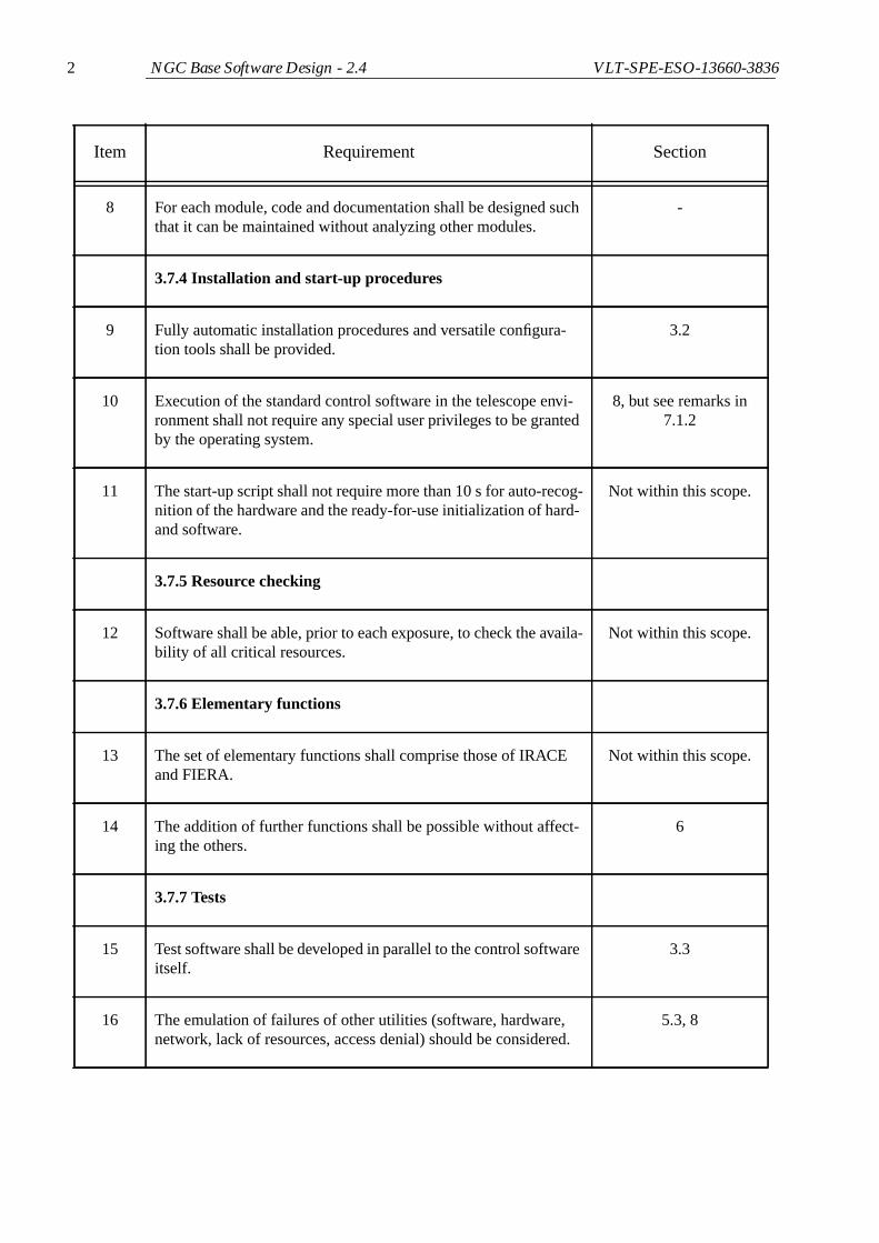
2 NGC Base Software Design - 2.4 VLT-SPE-ESO-13660-3836
8 For each module, code and documentation shall be designed suchthat it can be maintained without analyzing other modules.
-
3.7.4 Installation and start-up procedures
9 Fully automatic installation procedures and versatile configura-tion tools shall be provided.
3.2
10 Execution of the standard control software in the telescope envi-ronment shall not require any special user privileges to be grantedby the operating system.
8, but see remarks in7.1.2
11 The start-up script shall not require more than 10 s for auto-recog-nition of the hardware and the ready-for-use initialization of hard-and software.
Not within this scope.
3.7.5 Resource checking
12 Software shall be able, prior to each exposure, to check the availa-bility of all critical resources.
Not within this scope.
3.7.6 Elementary functions
13 The set of elementary functions shall comprise those of IRACEand FIERA.
Not within this scope.
14 The addition of further functions shall be possible without affect-ing the others.
6
3.7.7 Tests
15 Test software shall be developed in parallel to the control softwareitself.
3.3
16 The emulation of failures of other utilities (software, hardware,network, lack of resources, access denial) should be considered.
5.3, 8
Item Requirement Section

NGC Base Software Design - 2.4 VLT-SPE-ESO-13660-3836 3
17 Standardized tests of the software corresponding to any supportedhardware configuration shall be possible by merely selecting asingle set of parameters.
8 (to a limited extend)
18 A sequence of tests of several hardware configurations shall bepossible without operator intervention.
8 (to a limited extend)
19 Means should be considered to let NGC keep track of the fre-quency of usage of its key functionalities as a way to set usage-oriented test priorities.
Not within this scope.
3.7.8 Times and timings
20 Without the VLT TIM, all absolute times shall be correct to withinless than 0.1s.
Not within this scope.
21 Relative synchronizations and time intervals shall be accurate tobetter than 0.1% or, for intervals less than 10s, to better than0.01s.
Not within this scope.
22 Stricter timing requirements shall be realized using TIM. 2.6, 6.3.3
3.7.9 Special modes
23 Support of the following techniques (in the order of decreasingpriority) should be foreseen:
• nod and shuffle
• subpixel sampling and digital filtering so that duringan exposure the built-up of the S/N can be followedby performing a regression analysis for each pixel
• drift scanning
• non-destructive readout
• on-chip charge shifts by a user-definable amount (e.g.,for through-focus sequences)
7.2
24 Device type-specific modes offered by state-of-the-art IR detec-tors shall be included.
7.2
Item Requirement Section

4 NGC Base Software Design - 2.4 VLT-SPE-ESO-13660-3836
25 If centroiding functions need to be supported, this shall be possi-ble at a frame rate of 1 Hz for data arrays of up to 256 x 256 pixelsusing a single Gaussian fit or similar. For much smaller dataarrays, rates of up to 100 Hz should be possible.
7.2
3.7.10 Consecutive exposures
26 If, e.g. due to on-line data processing, the time between end ofdetector readout and availability of the FITS file on disk becomesa significant overhead, it shall be possible to configure the soft-ware such that the next exposure begins right after the previousreadout.
Not within this scope.
3.7.11 Windowing and on-chip binning
27 Standard windowing and on-chip binning shall be provided 6.3.2, 7.2
28 The number of windows should only be limited by the capabilitiesof the detectors.
6.3.2, 7.2
3.7.12 Pixel processor
29 A pixel processor shall be embedded in the system. Its interfacesto the remainder of the system shall be designed such that areplacement of the hardware plus operating system and/or of theprocessing software can be fully transparent to all other subsys-tems.
7
30 The following operations shall be supported from the beginning:averaging of frames with and without removal of outliers (e.g.,particle events)
• bias subtraction
• centroiding of point sources
• TBC
(If performance reasons so require, the implementation may bedetector dependent.)
7.2, 7.2.6
31 Close integration with NGC of a general-purpose image process-ing system featuring a user friendly scripting language could beconsidered.
7.3.2
Item Requirement Section

NGC Base Software Design - 2.4 VLT-SPE-ESO-13660-3836 5
32 More desirable is an interface to the ESO DFS and the inclusionof general-purpose algorithms and recipes in the DFS CPL for re-use by data reduction pipelines.
Not within this scope.
3.7.13 ALMA control software
33 If this is in the general interest of ESO and supported by the Tech-nology Division, elements of the ALMA control software may beused.
TBD
3.7.14 Special utilities
34 For multi-port systems, bias equalization to within better than 1%shall be possible on demand but without any further operatorsupervision.
7.2
3.8 External interfaces
35 Ideally, external interfaces (e.g., commands, databases) presentlymaintained by IRACE and FIERA would be supported by NGCwith a minimum of changes so as to make the integration of NGCwith the ESO operations scheme as seamless as possible. How-ever, since in this regard the commonalities of FIERA and IRACEare very limited, this also limits backward compatibility.In no case shall NGC feature two different types of interfaces forthe same purpose.
Not within this scope.
3.8.1 Data format
36 The data format shall be compliant with the Data Interface Con-trol Document.
Not within this scope.
37 Comprehensive detector and electronics telemetry shall beincluded in the data headers.
Not within this scope.
38 From the FITS headers, it shall be possible to uniquely infer thecomplete set of hard- and software configuration and all parame-ter values.
Not within this scope.
Item Requirement Section

6 NGC Base Software Design - 2.4 VLT-SPE-ESO-13660-3836
39 A generalized, moderately configurable interface to real-timecomputers, e.g. for adaptive optics or fringe tracking applications,shall be defined (in cooperation with ESO software engineersworking downstream from such an interface).
Not within this scope.
40 It could be advantageous that (a possibly special incarnation of)the pixel processor can serve as the real-time computer (or viceversa).
TBD
41 Latency shall not exceed 100 us. Not within this scope.
3.8.3 Real-time display
42 An interface to the RTD shall be provided. 7.3.1
43 For high frame rates, it shall be possible to request only every nthframe to be displayed.
7.2
44 Adaptive auto-selection shall be supported. 7.2
3.8.4 VLT telescope control system
45 It shall be possible to synchronize detector operations with thefollowing functions:
• Telescope nodding
• M2 chopping
• Non-sidereal tracking
2.6, 2.7, 6.3.3, 6.3.4
3.8.5 VLT time distribution system
46 The possibility of an interface to the VLT Time Interface Moduleshall be foreseen.
2.7, 6.3.4
47 -52
Reserved.
3.11 Diagnostic tools
Item Requirement Section

NGC Base Software Design - 2.4 VLT-SPE-ESO-13660-3836 7
3.11.1 Hardware self-test
53 The hardware shall be able to execute a comprehensive self-test. Itshall be possible to start it by pressing a physical button as well asby software. Due consideration shall be given to the protection ofthe detectors. The execution shall not exceed 5 minutes. An auto-matic log shall be produced.
6.6, 3.5
54 In order to save space on the electronics boards, it is acceptable tolet remote software (e.g., on the xLCU) execute these tests withhardware only reporting its status. This software shall be devel-oped in parallel to the one of the hardware.
6.6
3.11.2 Read-back of parameter values
55 It shall be possible to read back the actual values of all parametersset by software.
Not within this scope.
3.11.3 Automatic identification of hardware components
56 All LRUs (line Replaceable Unit) shall have a unique identifica-tion that is readable by software.
2.1, 6.1
57 An extension also to detectors shall be considered. TBD, must be sup-ported by hardware
58 Software shall be able to use this information for auto-configura-tion.
6.1
3.11.4 Error handling
59 Meaningful error messages and log files are essential; they shallenable software staff not familiar with the software or its scope toidentify and fix minor problems. Different severity levels shall bedistinguished. The status and options for the next actions shall beclear at all times.
3.5, 3.6
60 It shall be possible to set the severity level up to which automaticrecoveries from errors shall be attempted.
Not within this scope.
Item Requirement Section

8 NGC Base Software Design - 2.4 VLT-SPE-ESO-13660-3836
61 After a failed data saving, the OS shall have the possibility torecover the last frame.
Not within this scope.
62 After an interruption in the power supply, software should be ableto automatically restore the status at the beginning of the last suc-cessful exposure.
Not possible.
3.12 Support of engineering work
3.12.1 Engineering mode
63 There shall be a password-protectable engineering mode. It maycontain extra modules and options while otherwise may be omit-ted for reasons of convenience. However, modules used for nor-mal operations shall be identical.
8
64 This mode shall offer access to all essential elementary detectorcontrol functions and allow hardware engineers rapid proto-typ-ing of experimental software.
8
3.12.2 Change of parameters
65 A change of software-configurable parameters shall not require are-start of the system and, where possible, be supported also dur-ing readout. This would also benefit multi-mode instrumentswhere, e.g., imaging and spectroscopy require different parametersets for optimal performance. Switching between modes shall notlead to any hysteresis.
6.2, 7.2.2
66 A mechanism shall be implemented to reduce the risk of out-of-range parameter values being set accidentally that could damagethe connected detector(s). One possibility might be to let the con-troller hardware request a unique electronic ID (such as the serialnumber) from the detector.
TBD
67 An interface to BOB shall be provided that permits parameter val-ues to be set from dedicated observation blocks / observing tem-plates. To take advantage of this, laboratory setups would need tobe able to emulate VLT-compatible instruments to the extent thatVLT control software Sequencer scripts can be executed.
Not within this scope.
Item Requirement Section
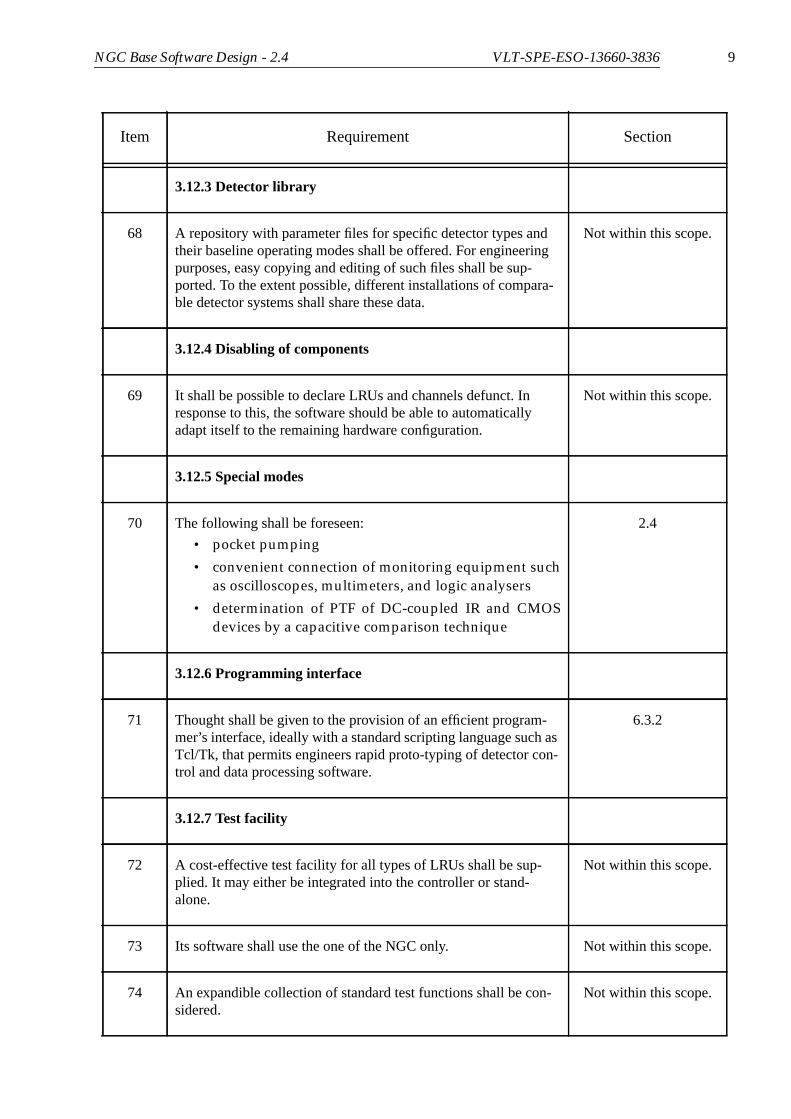
NGC Base Software Design - 2.4 VLT-SPE-ESO-13660-3836 9
3.12.3 Detector library
68 A repository with parameter files for specific detector types andtheir baseline operating modes shall be offered. For engineeringpurposes, easy copying and editing of such files shall be sup-ported. To the extent possible, different installations of compara-ble detector systems shall share these data.
Not within this scope.
3.12.4 Disabling of components
69 It shall be possible to declare LRUs and channels defunct. Inresponse to this, the software should be able to automaticallyadapt itself to the remaining hardware configuration.
Not within this scope.
3.12.5 Special modes
70 The following shall be foreseen:
• pocket pumping
• convenient connection of monitoring equipment suchas oscilloscopes, multimeters, and logic analysers
• determination of PTF of DC-coupled IR and CMOSdevices by a capacitive comparison technique
2.4
3.12.6 Programming interface
71 Thought shall be given to the provision of an efficient program-mer’s interface, ideally with a standard scripting language such asTcl/Tk, that permits engineers rapid proto-typing of detector con-trol and data processing software.
6.3.2
3.12.7 Test facility
72 A cost-effective test facility for all types of LRUs shall be sup-plied. It may either be integrated into the controller or stand-alone.
Not within this scope.
73 Its software shall use the one of the NGC only. Not within this scope.
74 An expandible collection of standard test functions shall be con-sidered.
Not within this scope.
Item Requirement Section
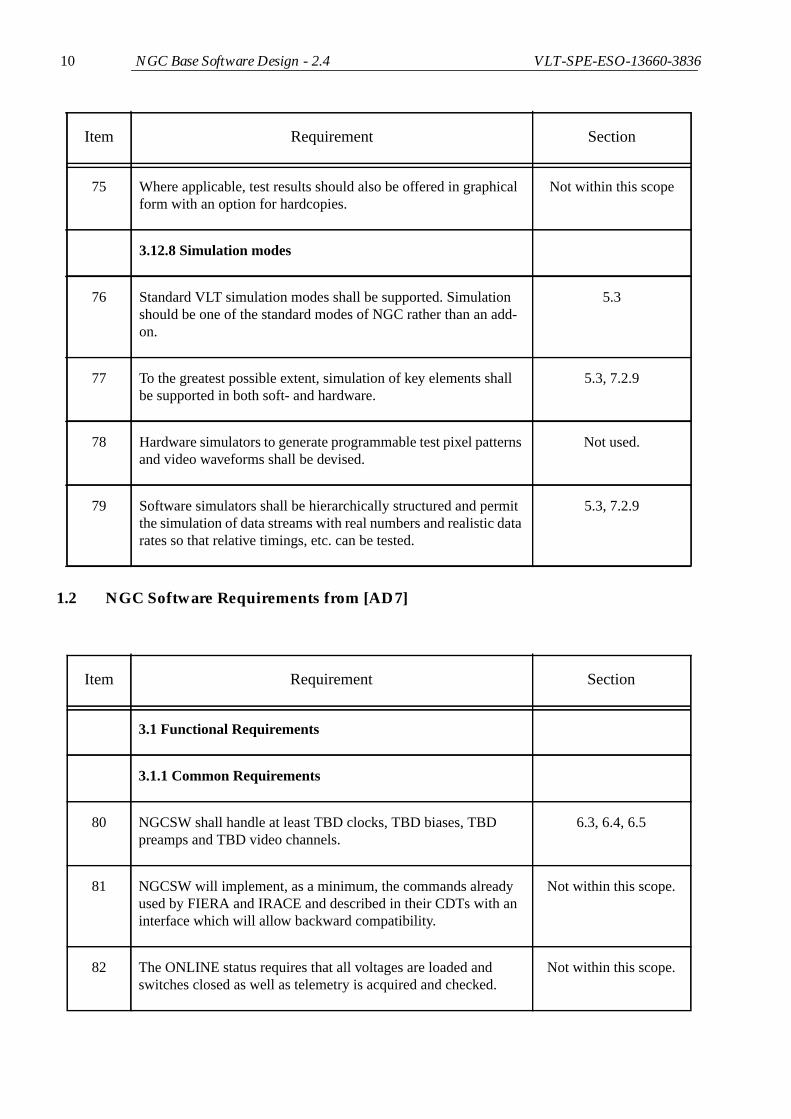
10 NGC Base Software Design - 2.4 VLT-SPE-ESO-13660-3836
1.2 NGC Software Requirements from [AD7]
75 Where applicable, test results should also be offered in graphicalform with an option for hardcopies.
Not within this scope
3.12.8 Simulation modes
76 Standard VLT simulation modes shall be supported. Simulationshould be one of the standard modes of NGC rather than an add-on.
5.3
77 To the greatest possible extent, simulation of key elements shallbe supported in both soft- and hardware.
5.3, 7.2.9
78 Hardware simulators to generate programmable test pixel patternsand video waveforms shall be devised.
Not used.
79 Software simulators shall be hierarchically structured and permitthe simulation of data streams with real numbers and realistic datarates so that relative timings, etc. can be tested.
5.3, 7.2.9
Item Requirement Section
3.1 Functional Requirements
3.1.1 Common Requirements
80 NGCSW shall handle at least TBD clocks, TBD biases, TBDpreamps and TBD video channels.
6.3, 6.4, 6.5
81 NGCSW will implement, as a minimum, the commands alreadyused by FIERA and IRACE and described in their CDTs with aninterface which will allow backward compatibility.
Not within this scope.
82 The ONLINE status requires that all voltages are loaded andswitches closed as well as telemetry is acquired and checked.
Not within this scope.
Item Requirement Section

NGC Base Software Design - 2.4 VLT-SPE-ESO-13660-3836 11
83 NGCSW will handle multiple independent detectors. 6
84 It shall be possible to read number of windows limited only bydetector properties
6.3.2, 7.2
85 Windows shall be read either in hardware through sequences or insoftware. The latter case implies that a full frame is read out andthen a window of data is computed in memory.
6.3.2, 7.2, 7.2.7, 7.3.1
86 Telemetry shall be available at all times, with the possibility tohave a separate period for logging on the VLT logMonitor.
6.4
87 NGCSW shall transfer all computed results to display (RTD) and/or to FITS-file.
7.2
88 Display visualization is done in parallel to all other data transfers(i.e. one may look at the DIT frame while storing the INT frameto disk and while the next data is already being processed).
7.2
89 If processing- or data-transfer-bandwidth exceeds the capacity ofone single computer, the task is split up to N computing units.
2.2, 7.2
90 In order to test the image data path, NGC must be able to producepre-defined data,
7.2.9
3.1.3 Infrared Specific Requirements
91 Each Pixel can be read out N times and an average is computed. 7.2
92 Subsampling and digital filtering of individual pixels shall be pos-sible.
7.2
93 The ONLINE status requires that the system also starts readout. Not within this scope.
94 In case reference values on special channels are read out (e.g.Hawaii2RG), NGC shall be able to interpolate through rows orcolumns.
7.2
95 Chopping mode shall be implemented 7.2
Item Requirement Section

12 NGC Base Software Design - 2.4 VLT-SPE-ESO-13660-3836
96 NGCSW shall be able to transfer bursts of raw data to FITS files. 7.2 (partially), [RD11]
97 Standard read-out modes:
• Uncorrelated
• Double correlated (reset-read-read)
• Double correlated (read-reset-read)
• Least square fit
• Fowler Sampling
7.2
3.2 External Interface Requirements
3.21 User Interfaces
98 NGCSW user interfaces will be developed following rulesdescribed in [RD39].
Not within this scope.
99 The user interface for telescope operations will merge functionali-ties of current FIERA and IRACE user interfaces.
Not within this scope.
100 Specific graphical interface may be developed in order to easeengineer’s work in the laboratory. These interfaces may be devel-oped not following the standards if their use is confined to labora-tory.
8
3.2.3 Software Interfaces
101 Sequencer programming shall be implemented using a scriptinglanguage.
6.3.2
102 The scripting language will allow evaluation of arithmetic formu-las at run-time.
6.3.2
103 The startup overhead of the script must be as short as possible. 6.3.2
104 Where no script is required a simple parsing can be done. 6.3.2
105 A graphical tool shall be implemented in order to have also thepossibility to program and visualize the sequences.
Not within this scope.
Item Requirement Section

NGC Base Software Design - 2.4 VLT-SPE-ESO-13660-3836 13
106 The format on disk of the sequences shall be ASCII. 6.3.2
107 Other formats, non ASCII, for ancillary data (e.g. for graphics)could be used, but must not be required for running the system.
6.3.2
108 The sequence programming will allow free use of setup parame-ters.
6.3.2
109 The chopper frequency may be input parameter or output parame-ter of the sequencer program.
6.3.2
110 Free placement of synchronization points with external trigger. 6.3
111 Read-out of multiple windows shall be configurable in program-ming.
6.3.2
112 Sub-pixel sampling (N samples per pixel) shall also be possible 6.3.2
113 The sequencer programming tool will also allow to emulate thereal sequencer.
5.3
114 Interface to standard RTD shall be provided. 7.3.1
115 The interface and the library to be used are given in [RD40]. 7.3.1
116 If needed flat-field frame and bad pixels mask shall be uploaded toNGCSW which will then distribute them to the relevant subsys-tem.
7.2.6
3.2.4 Communications Interfaces
117 Communication between internal subsystems of NGCSW shall beimplemented using VLTSW standard messaging tools as well asCCS database.
5.1, 5.2
118 Whenever not otherwise specified, the same standards will beused for all other communication interfaces.
5.1, 5.2
Item Requirement Section

14 NGC Base Software Design - 2.4 VLT-SPE-ESO-13660-3836
1.3 Adaptive Optics Requirements for NGC from [AD20]
3.3.2 Data Transfer
119 Data transfer rate to the IWS shall be limited only by readoutspeed.
7.2
120 An overhead of max. 5 seconds will be considered acceptable. 7.2
Item Requirement Section
AONGCREQ-004 Number of detectors controlled from single NGC: 1-4 2, 6
AONGCREQ-005 It should be possible to control multiple detectors with a sin-gle NGC.
2, 6
AONGCREQ-006 The detectors controlled by a single NGC all be read with thesame read-mode and frame rate. Operations such as start andstop, should operate on all detectors simultaneously.
2, 6, 7.2
AONGCREQ-007 It should be possible to synchronize the start of a readsequence between NGCs
2.7, 6.3.4
AONGCREQ-008 The synchronization should allow the start of the readout inseparate NGCs to be started within the frame jitter time.
2.7, 6.3.4
AONGCREQ-009 Ability to visualise 1 of N frames asynchronously on instru-ment WS using standard RTD, the value of N will be chosento allow visualisation on the WS of 1-4Hz, the maximumframe rate required to the WS will be 50Hz.
7.2
AONGCREQ-010 Ability store 1 of N frames asynchronously in FITS formaton instrument WS, the value of N will be defined to allow amaximum frame rate of 50Hz.
7.2
Item Requirement Section

NGC Base Software Design - 2.4 VLT-SPE-ESO-13660-3836 15
AONGCREQ-011 Ability to store a series of N guaranteed consecutive frames,where N should be sufficient to store a minimum of 2 secondsof data with a goal of 10s.
7.2
AONGCREQ-012 At least one ROI (windowing/regions of interest) per detectorshould be supported, as a goal multiple ROIs.
6.3.2, 7.2, 7.2.7,7.3.1
AONGCREQ-013 It should be possible to update the ROI definition (at a mini-mum start coordinates) dynamically when a loop of readoutsis in operation.
-
AONGCREQ-014 Ability to synchronize the start of a readout sequence with anexternal trigger to within 30 micro seconds.
2.7, 6.3.4
AONGCREQ-015 1x1 to 16x16 defined in steps of 1 pixel binning is the samefor each window within a given detector.
6.3.2, 7.2, 7.2.7,7.3.1
AONGCREQ-024 It should be possible to command the NGC to execute adefined read sequence for the defined mosaic
6.3.2
AONGCREQ-025 N times. 6.3.2
AONGCREQ-026 with a user definable (in microseconds) delay (from 0 toTBD) between executions
6.3.2
AONGCREQ-027 where N is a value between 1 and Inf. 6.3.2
AONGCREQ-028 A stop command for a given mosaic should stop the currentloop of readout sequences at the completion of the next cycle
6.3.3
AONGCREQ-028a
It should be possible to instruct the NGC to pass a 15bit dataramp over the real time data link in a standard frame includ-ing both start and end of frame words at frame rates up to themaximum supported
TBD - must besupported by
hardware
AONGCREQ-029 As a goal it should be possible to load simulated images intothe NGC memory and have them ‘played back’ over the RTdata link as though coming from a normal readout sequence.
Not supported byHW.
Item Requirement Section

16 NGC Base Software Design - 2.4 VLT-SPE-ESO-13660-3836
AONGCREQ-030 The replay speed should be a user parameter up to the maxi-mum possible frame rate.
Not supported byHW.
AONGCREQ-038 Define one (or more) ROIs for a specified detector with startpixel and window dimensions.
6.3.2, 7.2, 7.2.7,7.3.1
AONGCREQ-039 Define readout mode for detector mosaic. Not within thisscope.
AONGCREQ-040 Enable/Disable storage of detector frames. 7.2.5, 7.3.1
AONGCREQ-041 Define sub-sampling of readout to be passed to instrumentworkstation for visualisation or storage.
7.2
AONGCREQ-042 Start readout of mosaic of detectors for N cycles, 1<=N<=Inf 6.3.2, 6.3.3
AONGCREQ-043 with optional synchronization with external synch signal. 2.7, 6.3.4
AONGCREQ-044 Stop readout of a mosaic of detectors. 6.3.3
AONGCREQ-045 Acquire and store a contiguous set of N frames from a‘group’ of detectors.
6.3.2, 7.2
AONGCREQ-046 Upload a set of detector frames to be replayed in simulationmode.
Not supported byHW.
AONGCREQ-047 Replay previously uploaded simulated data frames at definedloop frequency.
Not supported byHW.
Item Requirement Section

NGC Base Software Design - 2.4 VLT-SPE-ESO-13660-3836 1
1 APPENDIX
1.1 ngcb2Drv - Command Definition Table
PUBLIC_COMMANDS
COMMAND= BREAKFORMAT= AREPLY_FORMAT= AHELP_TEXT=Interrupt server.@
COMMAND= EXITFORMAT= AREPLY_FORMAT= AHELP_TEXT=Make the server exit/terminate.@
COMMAND= KILLFORMAT= AREPLY_FORMAT= AHELP_TEXT=Send a KILL signal to the server.@
COMMAND= MSGDLOGFORMAT= AREPLY_FORMAT= AHELP_TEXT=Disable autologging of messages sent or received by the application.@
COMMAND= MSGELOGFORMAT= AREPLY_FORMAT= AHELP_TEXT=Enable autologging of messages sent or received by the application.@
COMMAND= ONLINEFORMAT= AREPLY_FORMAT= AREPLY_PARAMETERS=
PAR_NAME= donePAR_TYPE= STRINGPAR_DEF_VAL= “OK”
HELP_TEXT=Connect server to interface device.@
COMMAND= PINGFORMAT= AREPLY_FORMAT= AREPLY_PARAMETERS=
PAR_NAME= donePAR_TYPE= STRINGPAR_DEF_VAL= “OK”
HELP_TEXT=Make a check of the functioning of the server and send back an

2 NGC Base Software Design - 2.4 VLT-SPE-ESO-13660-3836
overall status message.@
COMMAND= RDADDRFORMAT= BREPLY_FORMAT= BHELP_TEXT=Binary read from a module address.@
COMMAND= RESETFORMAT= AREPLY_FORMAT= AREPLY_PARAMETERS=
PAR_NAME= donePAR_TYPE= STRINGPAR_DEF_VAL= “OK”
HELP_TEXT=Send a reset instruction to the interface device.@
COMMAND= SIMULATSYNONYMS= SIMFORMAT= AREPLY_FORMAT= AREPLY_PARAMETERS=
PAR_NAME= donePAR_TYPE= STRINGPAR_DEF_VAL= “OK”
HELP_TEXT=Switch to simulation mode. A simulator will be used instead ofaccessing the physical interface device.@
COMMAND= STANDBYFORMAT= AREPLY_FORMAT= AREPLY_PARAMETERS=
PAR_NAME= donePAR_TYPE= STRINGPAR_DEF_VAL= “OK”
HELP_TEXT=Disconnect server from interface device.@
COMMAND= STATUSFORMAT= AREPLY_FORMAT= AREPLY_PARAMETERS=
PAR_NAME= statusPAR_TYPE= INTEGERPAR_DEF_VAL= 0
HELP_TEXT=Get physical interface device status.@
COMMAND= STOPSIMFORMAT= AREPLY_FORMAT= AREPLY_PARAMETERS=
PAR_NAME= donePAR_TYPE= STRINGPAR_DEF_VAL= “OK”

NGC Base Software Design - 2.4 VLT-SPE-ESO-13660-3836 3
HELP_TEXT=Switch to normal operation mode.@
COMMAND= TIMEOUTFORMAT= APARAMETERS=
PAR_NAME= secondsPAR_TYPE= INTEGERPAR_OPTIONAL=NO
REPLY_FORMAT= AREPLY_PARAMETERS=
PAR_NAME= donePAR_TYPE= STRINGPAR_DEF_VAL= “OK”
HELP_TEXT=Set a new timeout (in seconds) for the device i/o.@
COMMAND= VERBOSEFORMAT= APARAMETERS=
PAR_NAME= onPAR_TYPE= LOGICALPAR_OPTIONAL=YES
PAR_NAME= offPAR_TYPE= LOGICALPAR_OPTIONAL=YES
REPLY_FORMAT= AHELP_TEXT=Switch verbose mode on/off.@
COMMAND= VERSIONFORMAT= APARAMETERS=REPLY_FORMAT= AHELP_TEXT=Return the present server version.@
COMMAND= WRADDRFORMAT= BREPLY_FORMAT= BHELP_TEXT=Binary write to a module address.@
MAINTENANCE_COMMANDS
TEST_COMMANDS
// --- oOo ---

4 NGC Base Software Design - 2.4 VLT-SPE-ESO-13660-3836
1.2 ngcbDrvCom
NAME
ngcbDrvCom - NGC driver interface for communication line
SYNOPSIS
#include "ngcbDrv.h"
int ngcbComOpen(const char *name, char *erms)
int ngcbComClose(int fd)
int ngcbComReset(int fd)
int ngcbComTimeout(int fd, int seconds)
int ngcbComRead(int fd, char *buffer, int size, char *erms)
int ngcbComWrite(int fd, char *buffer, int size, char *erms)
int ngcbComReadStatus(int fd)
int ngcbComErrStatus()
void ngcbComErrStr(int status, char *errStr)
void ngcbComStatStr(int status, char *errStr)
DESCRIPTION
ngcbComOpen() opens connection to the front-end.
ngcbComClose() closes the connection to the front-end.
ngcbComReset() performs a device reset of the subsystem.
ngcbComTimeout() sets the timeout for read/write accesses in seconds.
ngcbComRead() reads a number of bytes from the device.
ngcbComWrite() writes a number of bytes to the device.
ngcbComReadStatus() returns the actual value of the communicationstatus register.
ngcbComErrStatus() returns the saved status value of the lastfaulty I/O. The saved value is reset to zero on each deviceopen/close.
ngcbComErrStr() returns in <errStr> an error message matchingthe given <status>.
ngcbComStatStr() returns in <statStr> a status message matchingthe given <status>.
RETURN VALUES
ngcbComOpen returns an open file descriptor in case of success.A value of -1 indicates an error.
If not specified otherwise all other functions return zero incase of success. A value of -1 indicates an error.
<erms> will contain an error-message in case of failure.

NGC Base Software Design - 2.4 VLT-SPE-ESO-13660-3836 5
1.3 ngcbDrvDma
NAME
ngcbDrvDma - interface library to NGC DMA driver
SYNOPSIS
#include "ngcbDrv.h"
int ngcbDmaOpen(const char *devName, ngcb_dma_t *dma, char *erms)
int ngcbDmaClose(ngcb_dma_t *dma, char *erms)
int ngcbDmaAlloc(ngcb_dma_t dma, unsigned char **buffer, int num, unsigned long size, char *erms)
void ngcbDmaFree(ngcb_dma_t dma, unsigned char **buffer, int num)
int ngcbDmaInit(ngcb_dma_t *dma, unsigned char **buffer, int num, unsigned long size, unsigned int *doneCount, char *erms)
int ngcbDmaStop(ngcb_dma_t dma, char *erms)
int ngcbDmaClr(ngcb_dma_t dma, char *erms)
int ngcbDmaGetCnt(ngcb_dma_t dma, unsigned int *cnt, char *erms)
int ngcbDmaWait(ngcb_dma_t dma, unsigned int cnt, char *erms)
int ngcbDmaStat(ngcb_dma_t dma, int *byteCount, char *erms)
int ngcbDmaOverflow(ngcb_dma_t dma)
DESCRIPTION
ngcbDmaOpen() opens the dma interface driver with device name<devName>.
ngcbDmaClose() closes the dma interface driver referred to bythe device handle <dma>.
ngcbDmaAlloc() allocates <num> DMA ringbuffer elements withthe specified size (in bytes). The <num> buffer pointers have tobe allocated by the calling application.
ngcbDmaFree() frees the DMA ringbuffer space previously allocatedwith ngcbDmaAlloc().
ngcbDmaInit() initiates a sustained ringbuffered DMA-read. Thearray of buffers has to be passed to the routine. <num> is thenumber of ringbuffer elements and <size> is the size (in bytes)of each buffer element. As current Linux kernel versions do nolonger support DMA to user-space memory, the current implementationignores the <buf>, <num> and <size> parameters and does the DMAto the buffers allocated/mapped in the kernel with ngcbDmaAlloc().The parameters are left in here as user-space DMA may re-appear againand the applications may benefit from such an implementation. To keepthe user space code compatible with such cases it is stronglyrecommended to pass the <buf>, <num> and <size> values from thengcbDmaAlloc() routine into here. <doneCount> is set by theroutine as initial buffer counter. Usually this will be zero,but the value might differ when using future driver versions.

6 NGC Base Software Design - 2.4 VLT-SPE-ESO-13660-3836
ngcbDmaStop() stops the current DMA.
ngcbDmaClr() clears all DMA data FIFOs.
ngcbDmaGetCnt() gets the current buffer counter.
ngcbDmaWait() suspends the calling routine until the next DMA-bufferhas been received.
ngcbDmaStat() sets <byteCount> to the number of bytes which arestill left in the current DMA.
ngcbDmaOverflow() returns a value of 1 in case of a dataFIFO overflow. Otherwise, a value of 0 is returned.
RETURN VALUES
ngcbDmaOverflow returns a value of 1 in case of an inputfifo overflow. Otherwise, a value of 0 is returned.
All other functions:
Upon successful completion, a value of 0 is returned.Otherwise a value of -1 is returned and erms contains anerror string.
CAUTIONS
The ngcbDmaOpen() function must always be called before any of theother functions in this set can be used. The device should alwaysbe closed before being re-opened.
SEE ALSO
ngcbDmaPci(3), ngcbDma0(3)

NGC Base Software Design - 2.4 VLT-SPE-ESO-13660-3836 7
1.4 ngcbPrio
NAME
ngcbPrio, ngcbGetPrio, ngcbSetPrio - priority control
SYNOPSIS
#include "ngcb.h"
int ngcbGetPrio(int *priority, int *class, int *quantum)int ngcbSetPrio(int priority, int class, int quantum)
DESCRIPTION
Priority control:
The time quantum is expressed in microseconds (only relevantfor real-time class).
ngcbTQ_INF: infitite time quantumngcbTQ_DEF: default time quantumngcbTQ_NC: do not change previous value
classes: ngcbPRI_RT - real time class ngcbPRI_TS - time sharing class
The priority is rising with higher values.
RETURN VALUES
In case of failure -1 is returned, otherwise zero.
1.5 ngcbThread
NAME
ngcbThread, ngcbThrCreate, ngcbThrExit, ngcbThrKill, ngcbThrJoin - thread routines
SYNOPSIS
#include "ngcbThread.h"
int ngcbThrCreate(void *(*startFunc)(void *), void *arg, long flags, ngcb_thread_t *thread)
void ngcbThrExit(void *status)
int ngcbThrKill(ngcb_thread_t thread, int sig)
int ngcbThrJoin(ngcb_thread_t thread, ngcb_thread_t *departed, void **status)
ngcb_thread_t ngcbThrId()
DESCRIPTION
Thread routines (behave like pthread/POSIX or thread/SOLARIS).
CAUTIONS
ngcbThread.h also provides definitions to support the same nomenclatureas used for the Solaris implementation. See also the man pages forthr_create(3THR), thr_join(3THR), thr_kill(3THR) and thr_exit(3THR)on Solaris.
SEE ALSO
thr_create(3THR), thr_join(3THR), thr_kill(3THR), thr_exit(3THR)

8 NGC Base Software Design - 2.4 VLT-SPE-ESO-13660-3836
1.6 ngcbSem
NAME
ngcbSem, ngcbSemInit, ngcbSemDestroy, ngcbSemWait, ngcbSemPost, ngcbSemTryWait,ngcbSemCnt, ngcbSemLock, ngcbSemUnlock, ngcbSemTryLock, ngcbRwLockInit,ngcbRwLockDestroy, ngcbRwRdLock, ngcbRwWrLock, ngcbRwUnlock, ngcbRwTryRdLock,ngcbTryWrLock - wrapping routines for semaphores and readers/writer-locks using theposix mutex routines
SYNOPSIS
#include "ngcbThread.h"
int ngcbSemInit(ngcb_sema_t *sp, unsigned int count, int type, void *arg)
int ngcbSemDestroy(ngcb_sema_t *sp)
int ngcbSemLock(ngcb_sema_t *sp)
int ngcbSemUnlock(ngcb_sema_t *sp)
int ngcbSemTryLock(ngcb_sema_t *sp)
int ngcbSemWait(ngcb_sema_t *sp)
int ngcbSemPost(ngcb_sema_t *sp)
int ngcbSemTryWait(ngcb_sema_t *sp)
int ngcbSemCnt(ngcb_sema_t *sp)
int ngcbRwLockInit(ngcb_lock_t *rwlp, int type, void *arg)
int ngcbRwDestroy(ngcb_lock_t *rwlp)
int ngcbRwRdLock(ngcb_lock_t *rwlp)
int ngcbRwTryRdLock(ngcb_lock_t *rwlp)
int ngcbRwWrLock(ngcb_lock_t *rwlp)
int ngcbRwTryWrLock(ngcb_lock_t *rwlp)
int ngcbRwUnlock(ngcb_lock_t *rwlp)
DESCRIPTION
Routines for semaphores and readers/writer-locks using the posixmutexes:
ngcbSemInit() creates a new counting semaphore. <count> specifies theinitial semaphore counter value.
int ngcbSemDestroy() destroys the specified semphore.
void ngcbSemLock() acquires the binary lock associated with thesemaphore. The function will block until the lock is available.
void ngcbSemUnlock() releases the binary lock associated withthe semaphore.
int ngcbSemTryLock() tries to get the binary lock associated withthe semaphore. If the lock is not available, the function returns (-1).
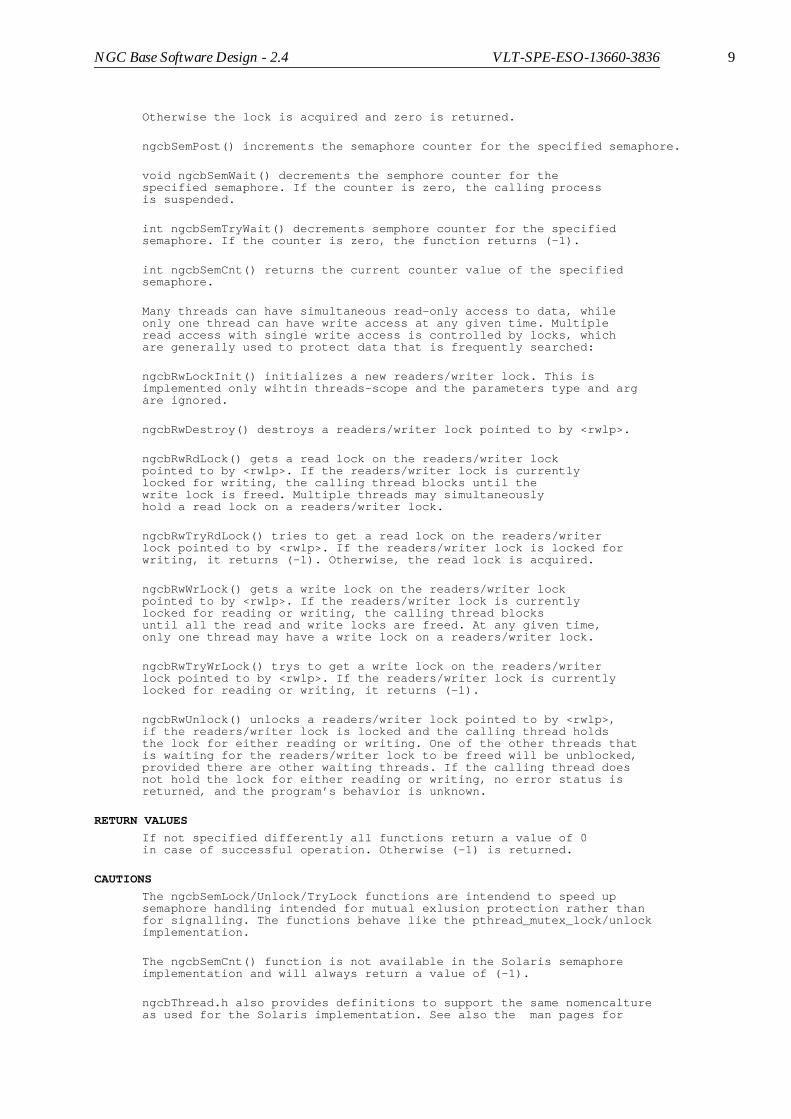
NGC Base Software Design - 2.4 VLT-SPE-ESO-13660-3836 9
Otherwise the lock is acquired and zero is returned.
ngcbSemPost() increments the semaphore counter for the specified semaphore.
void ngcbSemWait() decrements the semphore counter for thespecified semaphore. If the counter is zero, the calling processis suspended.
int ngcbSemTryWait() decrements semphore counter for the specifiedsemaphore. If the counter is zero, the function returns (-1).
int ngcbSemCnt() returns the current counter value of the specifiedsemaphore.
Many threads can have simultaneous read-only access to data, whileonly one thread can have write access at any given time. Multipleread access with single write access is controlled by locks, whichare generally used to protect data that is frequently searched:
ngcbRwLockInit() initializes a new readers/writer lock. This isimplemented only wihtin threads-scope and the parameters type and argare ignored.
ngcbRwDestroy() destroys a readers/writer lock pointed to by <rwlp>.
ngcbRwRdLock() gets a read lock on the readers/writer lockpointed to by <rwlp>. If the readers/writer lock is currentlylocked for writing, the calling thread blocks until thewrite lock is freed. Multiple threads may simultaneouslyhold a read lock on a readers/writer lock.
ngcbRwTryRdLock() tries to get a read lock on the readers/writerlock pointed to by <rwlp>. If the readers/writer lock is locked forwriting, it returns (-1). Otherwise, the read lock is acquired.
ngcbRwWrLock() gets a write lock on the readers/writer lockpointed to by <rwlp>. If the readers/writer lock is currentlylocked for reading or writing, the calling thread blocksuntil all the read and write locks are freed. At any given time,only one thread may have a write lock on a readers/writer lock.
ngcbRwTryWrLock() trys to get a write lock on the readers/writerlock pointed to by <rwlp>. If the readers/writer lock is currentlylocked for reading or writing, it returns (-1).
ngcbRwUnlock() unlocks a readers/writer lock pointed to by <rwlp>,if the readers/writer lock is locked and the calling thread holdsthe lock for either reading or writing. One of the other threads thatis waiting for the readers/writer lock to be freed will be unblocked,provided there are other waiting threads. If the calling thread doesnot hold the lock for either reading or writing, no error status isreturned, and the program’s behavior is unknown.
RETURN VALUES
If not specified differently all functions return a value of 0in case of successful operation. Otherwise (-1) is returned.
CAUTIONS
The ngcbSemLock/Unlock/TryLock functions are intendend to speed upsemaphore handling intended for mutual exlusion protection rather thanfor signalling. The functions behave like the pthread_mutex_lock/unlockimplementation.
The ngcbSemCnt() function is not available in the Solaris semaphoreimplementation and will always return a value of (-1).
ngcbThread.h also provides definitions to support the same nomencaltureas used for the Solaris implementation. See also the man pages for

10 NGC Base Software Design - 2.4 VLT-SPE-ESO-13660-3836
sema_init(3THR) and rwlock_init(3THR) on Solaris.
SEE ALSO
pthread_mutex_lock(3), pthread_mutex_unlock(3), sema_init(3THR),rwlock_init(3THR)

NGC Base Software Design - 2.4 VLT-SPE-ESO-13660-3836 11
1.7 ncgbTHREAD Class
NAME
ngcbTHREAD - C++ interface for posix threads
SYNOPSIS
#include <ngcbTHREAD.h>
ngcbTHREAD baseClass();ngcbTHREAD newThread(this, (ngcbPROCESS_T)&process, (void *)arg);
DESCRIPTION
C++ interface for posix threads.
PUBLIC METHODS
ngcbTHREAD(); Constructor method providing a base class for all applications, which want to use this interface.
ngcbTHREAD(ngcbTHREAD *appl, ngcbPROCESS_T process, void *arg) Constructor for a thread-object. This will start the specified process, which is declared in the application class. A pointer to the calling application class is passed in <appl>. <arg> passes a pointer to an application specific argument through to the called process. The <process> must be a member function of the application class. The <process> must be of type:
void <appl>::Process(void *arg)
The application class must be derived from the ncgbTHREAD class. A pipe is created to be able to trigger the created process via a select call.
virtual ~ngcbTHREAD(); Destructor method.
irtual ngcbTHREAD *NewThread(ngcbTHREAD *appl, ngcbPROCESS_T process, void *arg); Creates a new thread object, statring the specified process. Procedural interface to threwad-object creation with the <new> operator.
int ThrCreate(ngcbTHREAD *appl, ngcbPROCESS_T process, void *arg, ngcbTHREAD_T *threadId, char *erms); Function to create a thread in the scope of the specified application class <appl>. <arg> passes a pointer to an application specific argument through to the called process. The <process> must be of type:
void <appl>::Process(ngcbTHREAD *thread, void *arg)
A thread-id is returned in <threadId> as a handle to be used in later calls to the ThrJoin() and ThrKill() member functions.
void ThrExit(); Function to be called by a thread before exiting.
int ThrKill(ngcbTHREAD_T threadId, int sig, char *erms); Function to send signal to a thread specified via the handle <threadId>. The <threadId> is retrieved by calling the ThrCreate() member function.
int ThrJoin(ngcbTHREAD_T threadId, char *erms); Function to join a thread specified via the handle <threadId>. The <threadId> is retrieved by calling the ThrCreate() member

12 NGC Base Software Design - 2.4 VLT-SPE-ESO-13660-3836
function. The calling process is suspended until the specified thread exits.
int ThrKill(int sig, char *erms);int ThrJoin(char *erms); Same as the above functions but these are used for killing/joining a thread-object constructed with the second constructor.
int Initialized(); Returns (1) in case a thread-object constructed with the second constructor was created successfully.
int FdIn(); Returns a file descriptor to be used in the thread for a wakeup select call.
int FdOut(); Returns a file descriptor to be written to in order to send a message to the called thread.
ngcbTHREAD_T ThreadId() Returns own thread id.
RETURN VALUES
If not specified otherwise all functions return (0) incase of success. If an error occured (-1) is returned and <erms>will contain an error-message.
EXAMPLES
class myCLASS: public ngcbTHREAD {
ngcbTHREAD *myThread_;
public: myCLASS() { myThread_ = (ngcbTHREAD *)NULL;
}
void MyProcess(ngcbTHREAD *thr, void *arg) { int fdThr = thr->FdIn();
... use fdThr in select call te get triggered for abort ... }
void StartMyProcess { myThread_ = NewThread(this, (ngcbPROCESS_T)&myCLASS::MyProcess, NULL);
if (myThread_ == (ngcbTHREAD *)NULL) { ... error handling ... } else if (!myThread_->Initialized()) { delete myThread_; ... error handling ... } }
void KillMyProcess { if (myThread_ != (ngcbTHREAD *)NULL) { delete myThread_; } }

NGC Base Software Design - 2.4 VLT-SPE-ESO-13660-3836 13
}
SEE ALSO
ngcbSem(3), ngcbThread(3), ngcbSEM(4)

14 NGC Base Software Design - 2.4 VLT-SPE-ESO-13660-3836
1.8 ngcbSEM Class
NAME
ngcbSEM - C++ interface for semaphores using the posix mutex routines
SYNOPSIS
#include <ngcbTHREAD.h>
ngcbSEM baseClass();
ngcbSEM sem(count);
DESCRIPTION
C++ interface for semaphores using the posix mutex routines.
PUBLIC METHODS
ngcbSEM(); Constructor method providing a base class for application specific semaphores.
ngcbSEM(unsigned int count); Constructor method for a counting semaphore object. <count> specifies the initial semaphore counter value.
virtual ~ngcbSEM(); Destructor method.
int Create(ngcbSEM_T *sp, unsigned int count, char *erms); Create a new counting semaphore. <count> specifies the initial semaphore counter value.
int Destroy(ngcbSEM_T *sp, char *erms); Destroy the specified semphore.
void Lock(ngcbSEM_T *sp); Acquire the binary lock associated with the semaphore. The function will block until the lock is available.
void Unlock(ngcbSEM_T *sp); Release the binary lock associated with the semaphore.
int TryLock(ngcbSEM_T *sp); Tries to get the binary lock associated with the semaphore. If the lock is not available, the function returns (-1). Otherwise the lock is acquired and zero is returned.
void Post(ngcbSEM_T *sp); Increment semaphore counter for the specified semaphore.
void Wait(ngcbSEM_T *sp); Decrement semphore counter for the specified semaphore. If the counter is zero, the calling process is suspended.
int TryWait(ngcbSEM_T *sp); Decrement semphore counter for the specified semaphore. If the counter is zero, the function returns (-1).
int Cnt(ngcbSEM_T *sp); Returns the current counter value of the specified semaphore.
void Lock(); Acquire the binary lock associated with the own semaphore object. The function will block until the lock is available.
void Unlock(); Release the binary lock associated with the own semaphore object.

NGC Base Software Design - 2.4 VLT-SPE-ESO-13660-3836 15
int TryLock(); Tries to get the binary lock associated with the oen semaphore. object. If the lock is not available, the function returns (-1). Otherwise the lock is acquired and zero is returned.
void Post(); Increment semaphore counter for own semaphore object.
void Wait(); Decrement semphore counter for own semaphore object. If the counter is zero, the calling process is suspended.
int TryWait(); Decrement semphore counter for own semaphore object. If the counter is zero, the function returns (-1).
int Cnt(); Returns the current counter value of the own semaphore object.
RETURN VALUES
If not specified otherwise all functions return (0) incase of success. If an error occured (-1) is returned and <erms>(if present) will contain an error-message.
CAUTIONS
The ngcbSemLock/Unlock/TryLock functions are intendend to speed upsemaphore handling intended for mutual exlusion protection rather thanfor signalling. The functions behave like the pthread_mutex_lock/unlockimplementation.
SEE ALSO
ngcbTHREAD(4), pthread_mutex_lock(3), pthread_mutex_unlock(3)
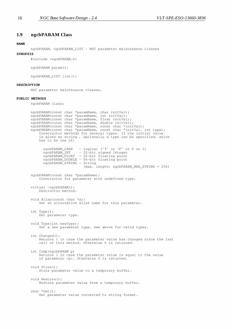
16 NGC Base Software Design - 2.4 VLT-SPE-ESO-13660-3836
1.9 ngcbPARAM Class
NAME
ngcbPARAM, ngcbPARAM_LIST - NGC parameter maintenance classes
SYNOPSIS
#include <ngcbPARAM.h>
ngcbPARAM param();
ngcbPARAM_LIST list();
DESCRIPTION
NGC parameter maintenance classes.
PUBLIC METHODS
ngcbPARAM class:
ngcbPARAM(const char *paramName, char initVal);ngcbPARAM(const char *paramName, int initVal);ngcbPARAM(const char *paramName, float initVal);ngcbPARAM(const char *paramName, double initVal);ngcbPARAM(const char *paramName, const char *initVal);ngcbPARAM(const char *paramName, const char *initVal, int type); Constructor methods for several types. If the initial value is given as string , optionally a type can be specified, which has to be one of:
ngcbPARAM_CHAR - logical (’T’ or ’F’ or 0 or 1) ngcbPARAM_INT - 32-bit signed integer ngcbPARAM_FLOAT - 32-bit floating point ngcbPARAM_DOUBLE - 64-bit floating point ngcbPARAM_STRING - string (max. length: ngcbPARAM_MAX_STRING = 256)
ngcbPARAM(const char *paramName); Constructor for parameter with undefined type.
virtual ~ngcbPARAM(); Destructor method.
void Alias(const char *a); Set an alternative alias name for this parameter.
int Type(); Get parameter type.
void Type(int newType); Set a new parameter type. See above for valid types.
int Changed(); Returns 1 in case the parameter value has changed since the last call of this method. Otherwise 0 is returned.
int Comp(ngcbPARAM p) Returns 1 in case the parameter value is equal to the value of parameter <p>. Otherwise 0 is returned.
void Store(); Store parameter value to a temporary buffer.
void Restore(); Restore parameter value from a temporary buffer.
char *Get(); Get parameter value converted to string format.

NGC Base Software Design - 2.4 VLT-SPE-ESO-13660-3836 17
int Set(const char *newValue); Convert value from string format to Type() and set this as new value.
int Set(char newValue); Convert value from logical format to Type() and set this as new value.
int Set(int newValue); Convert value from 32-bit signed integer format to Type() and set this as new value.
int Set(float newValue); Convert value from 32-bit floating point format to Type() and set this as new value.
int Set(double newValue); Convert value from 64-bit floating point format to Type() and set this as new value.
char ValChar(); Get parameter value converted to logical format.
int ValInt(); Get parameter value converted to 32-bit integer format.
float ValFloat(); Get parameter value converted to 32-bit floating point format.
double ValDouble(); Get parameter value converted to 64-bit floating point format.
char *ValString(); Get parameter value converted to string format - same as Get().
ngcbPARAM_LIST class:
ngcbPARAM_LIST(); Constructor method.
virtual ~ngcbPARAM_LIST(); Destructor method.
ngcbPARAM *Add(ngcbPARAM *newParam, int noDelete = 1); Add a new parameter object to the list. If a parameter object with the same name does already exist a pointer to the existing object is returned. Otherwise the same object is returned. If noDelete is set to zero, the parameter object will be deleted when the parameter is removed from the list, otherwise not (default).
ngcbPARAM *Add(const char *paramName, char initVal);ngcbPARAM *Add(const char *paramName, int initVal);ngcbPARAM *Add(const char *paramName, float initVal);ngcbPARAM *Add(const char *paramName, double initVal);ngcbPARAM *Add(const char *paramName, const char *initVal);ngcbPARAM *Add(const char *paramName, const char *initVal, int type); Add a parameter to the list. If the initial value is given as string , optionally a type can be specified, which has to be one of:
ngcbPARAM_CHAR - logical (’T’ or ’F’ or 0 or 1) ngcbPARAM_INT - 32-bit signed integer ngcbPARAM_FLOAT - 32-bit floating point ngcbPARAM_DOUBLE - 64-bit floating point ngcbPARAM_STRING - string (max. length: ngcbPARAM_MAX_STRING = 256)
A pointer to the new parameter object is returned. In case the parameter already exists, a pointer to the existing parameter

18 NGC Base Software Design - 2.4 VLT-SPE-ESO-13660-3836
object is returned. No check for NULL-pointer return value required.
ngcbPARAM *Add(const char *name); Add a parameter of undefined type to the list.
void Clear(); Remove all parameters.
void Remove(ngcbPARAM *param); Remove parameter object from list - resolve by object.
void Remove(const char *paramName); Remove parameter object from list - resolve by parameter name.
ngcbPARAM *Get(const char *paramName); Searches the list for a parameter object with the given name and returns a pointer to the object. If the parameter is not in the list, a NULL pointer is returned.
ngcbPARAM_LIST *First(); Returns the list entry point for "walking" through the list (see example below).
int Set(const char *paramName, char paramValue);int Set(const char *paramName, int paramValue);int Set(const char *paramName, float paramValue);int Set(const char *paramName, double paramValue);int Set(const char *paramName, const char *paramValue); Convenience functions to set a parameter value in the list.
int ValChar(const char *paramName, char *paramValue);int ValInt(const char *paramName, int *paramValue);int ValFloat(const char *paramName, float *paramValue);int ValDouble(const char *paramName, double *paramValue);int ValString(const char *paramName, char *paramValue); Convenience functions to get a parameter value from the list.
oid ClrCtrlList(int instance); Remove a controller (=sequencer) instance defined by its (sequential) instance number from all parameters inside the list.
oid ClrAcqList(int instance); Remove an acquisition process defined by its sequential instance number from all parameters inside the list.
PUBLIC DATA MEMBERS
ngcbPARAM class:
char name[64]; - parameter name
char alias[64]; - parameter alias name
char format[16]; - format for output of the Get(),ValString() methods. The default depends on the type:
ngcbPARAM_CHAR: "%c" ngcbPARAM_INT: "%d" ngcbPARAM_FLOAT/DOUBLE: "%6G" ngcbPARAM_STRING: not applicable
int fits; - flag to put the parameter into the FITS-header
char comment[28]; - optional comment for FITS-header
char unit[4]; - optional unit

NGC Base Software Design - 2.4 VLT-SPE-ESO-13660-3836 19
int flag; - storage space for application specifc flags (initial value is 0)
int ctrlList; - controller modules (sequencer), where the parameter is used. This is a bit-list maintaining up to 32 controller modules (bit 0 for 1st. module, bit 1 for 2nd. module and so on).
int acqList; - acquisition -processes, where the parameter is used. This is a bit-list maintaining up to 32 acquisition processes (bit 0 for 1st. module, bit 1 for 2nd. module and so on).
ngcbPARAM_LIST class:
ngcbPARAM *param; - pointer to parameter object
ngcbPARAM_LIST *next; - pointer to next list element
RETURN VALUES
If not specified differently, all functions return ngcbSUCCESSin case of success. Otherwise ngcbFAILURE is returned and theErrMsg() method will return a detailed error message.
EXAMPLES
Example for "walking" through a parameter list:
ngcbPARAM_LIST list; ngcbPARAM_LIST *l; ngcbPARAM *p;
// Add some parameters to the list... list.Add("Parameter1", "value"); list.Add("Parameter2", (char)1); list.Add("Parameter3", (int)5); list.Add("Parameter4", (float)0.1); list.Add("Parameter5", (double)0.2); list.Add("Parameter6", "1.1", ngcbPARAM_FLOAT);
p = list.Get("Parameter3"); if (p != (ngcbPARAM *)NULL) { strcpy(p->format, "0x%08x"); }
// Now just print the whole list for (l=list.First();l!=(ngcbPARAM_LIST *)NULL;l=l->next) { p = l->param; printf("%s = %s\n", p->name, p->Get()); }

20 NGC Base Software Design - 2.4 VLT-SPE-ESO-13660-3836
1.10 ngcbIFC Class
NAME
ngcbIFC - NGC interface class
SYNOPSIS
#include <ngcbIFC.h>
ngcbIFC interface();
DESCRIPTION
This class defines the general basic interface functions(Open, Close, Read, Write, etc.) to the NGC front end.It is functional for a locally installed standard NGC interfaceboard. In case the board is installed on another computer adriver interface process has to be started on that computer.Apart from the process startup which should happen via theoverloaded ExecServer()/KillServer() methods, the functionalityof the interface should be transparent to the application.Most public functions can be overloaded to provide the appropriateclient part of an interprocess communication.
PUBLIC METHODS
ngcbIFC(); Constructor method.
ngcbIFC(const char *name); Constructor method with default interface name.
virtual ~ngcbIFC(); Destructor method. This will in any case call the Close() method.
virtual int Open();virtual int Open(const char *name); Opens an interface device. If <name> is not specified the default device name from the constructor is taken. If a driver interface process is used, the name will contain the information which interface process to start on which host in an application specific format.
virtual int Close(); Closes an interface device.
virtual int ExecServer() Start driver interface process. The information which process to start on which host should be retrieved from the Name() method.
virtual int KillServer() Exit/Kill the driver interface interface process.
virtual int Connect(); Only for driver interface interfaces: connect through to device (i.e. send a command to the driver interface process to open the device).
virtual int Disconnect(); Only for driver interface interfaces: disconnect from the device (i.e. send a command to the driver interface process to close the device).
virtual int Fd(); Returns the (remote-) interface file descriptor.
virtual int Pid(); Returns the process id of the driver interface process or zero in case no driver interface process is used.

NGC Base Software Design - 2.4 VLT-SPE-ESO-13660-3836 21
virtual const char *Host(); Returns the host name of the driver interface process or a NULL pointer in case no driver interface process is used.
virtual int Reset(); Resets/intializes an interface device.
virtual int Read(int *buffer, int size); Read <size> words from device. The function returns the status word of the operation (see below for further details).
virtual int Write(int *buffer, int size); Write <size> words to device. The function returns the status word of the operation (see below for further details).
virtual int ReadAddr(ngcb_route_t route, int addr, int *buffer, int size, int *result); Reads size words from <addr> into buffer. <result> returns a status word for the operation (see below for further details). The operation implements a 4-byte-swap in case the calling computer has a big-endian architecture. The ngcb_route_t structure contains the following elements:
int numHdr; - number of headers to target including the terminating <0x2> int hdr[ngcbMAX_MOD]; - array of headers including the terminating <0x2>
virtual int WriteAddr(ngcb_route_t route, int addr, int *buffer, int size, int *result); Writes size words from buffer to <addr>. <result> returns a status word for the operation (see below for further details). The operation implements a 4-byte-swap in case the calling computer has a big-endian architecture.
int ReadAddr(ngcb_route_t route, int addr, int *buffer, int size);int WriteAddr(ngcb_route_t route, int addr, int *buffer, int size); Same as above but these interfaces hide the result code in case it is not needed. These methods call the virtual ReadAddr()/WriteAddr() method described above and need not to be overloaded by specific interface implementations.
virtual int Status() Returns the status of the interface board.
virtual int Timeout(int seconds); Sets a new timeout for read/write operations (in seconds).
virtual int Timeout(); Returns the current timeout (in seconds);
virtual int Running(); Returns 1 in case the driver interface process is running. Otherwise the function returns zero. This method is fully application specific.
virtual int Connected(); Returns 1 in case the driver interface process is connected to the device (i.e. device is open). Otherwise the function returns zero.
virtual void Verbose(const char *format, ...); Verbose method. A message is passed to the verbose output depending on the current verbose level. If the verbose level is zero, the message is ignored.
virtual void Log(const char *format, ...); Log method.

22 NGC Base Software Design - 2.4 VLT-SPE-ESO-13660-3836
virtual int Sim(int flag) Switch to simulation mode.
int WriteBuffer(int *buffer, int size, int *result) Writes a formatted buffer to the device. The format is: <hdr1 hdr2 ... hdrN address data1 data2 ...> <result> returns the status word for the operation. An error message can be retrieved via the Result2Err() method. The operation implements a 4-byte-swap in case the calling computer has a big-endian architecture. This method calls the virtual WriteAddr() method and needs not to be overloaded by specific interface implementations.
char *Name(); Returns the current interface(-device) name, as specified in the constructor or in the last Open() call. Can also be used to set a new (default-) name.
char *Type(); Returns a pointer to the interface type identifier string.
char *Arg(); Returns a pointer to the interface argument string. The argument string is intended to be passed to a driver interface process as command line.
void Instance(int instance); Sets an interface instance number. This ist just intended to store an outside reference index, to be given back via the Instance() method. The instance number is not used or changed inside this base interface class.
int Instance(); Returns the interface instance number.
int Standby(); Bring interface device to standby state. The driver interface process (if required) is alive, but the physical device is disconnected (i.e. closed).
int Online(); Bring interface device to on-line state. The driver interface process (if required) is alive and the physical device is connected (i.e. opened). If the device was disconnected before (i.e. was in standby- or off-state), a hardware reset is performed.
int Off(); Bring interface device to off-state. The physical devices is disconnected and the driver interface process is not alive.
char *ErrMsg(); Returns the current error message in case of failure.
int BigEndian(); Returns 1 in case the computer architecture is big-endian. Otherwise the function returns zero.
void Result2Err(char *errStr, int resultCode) Fills <errStr> with an error string matching the result code.
PUBLIC DATA MEMBERS
int ioError; - Indicates that the preceeding transaction caused an i/o error (generally the connection should be reset in that case).
int local; - If set to 1 the interface device is local. Otherwise it is installed on on a different computer and communication is done via a driver interface process.

NGC Base Software Design - 2.4 VLT-SPE-ESO-13660-3836 23
int sim; - Interface simulation level (0 = normal mode).
int xterm; - Start driver interface process in new terminal.
int verboseLevel; - Verbose level
int logLevel; - Log level
char thisHost[64]; - Host where this instance is launched
ngcb_vb_t verboseHandler; External verbose handler to be used instead of the built-in one:
void myHandler(int flag, const char *format, ...)
The usage is the as printf plus an additional flag which can be one of:
ngcbVB_PRINT - pass message to verbose output ngcbVB_LOG - log message
ngcb_es_t errStateHandler; External error-state handler of type:
void myHandler(char *erms, ngcbIFC *module)
RETURN VALUES
If not specified differently, all functions return ngcbSUCCESS in caseof success. Otherwise ngcbFAILURE is returned and ErrMsg() will contain adetailed error message.
The status word for device i/o (resultCode) may have the followingvalues:
ngcbRES_SUCCESS (0) - successful operation
Bit 0..7 - operation status byte (ngcbRES_ERR_IO is not set):
ngcbRES_OP_INVALID - invalid address or function ngcbRES_OP_FAILURE - operation failed ngcbRES_ERR_HDR - wrong header ngcbRES_ERR_ADDR - wrong address ngcbRES_ERR_DATA - wrong data ngcbRES_ERR_XSIZE - wrong transfer size ngcbRES_ERR_NOT_OPEN - device is not open
Bit 8..16 - combination of error bits (ngcbRES_ERR_IO is set):
ngcbRES_ERR_IO - i/o error ngcbRES_ERR_INTR - i/o interrupted ngcbRES_ERR_OPEN - error opening device ngcbRES_ERR_RESET - error resetting device ngcbRES_ERR_TIMEOUT - i/o timeout ngcbRES_ERR_LINK_DOWN - link channel down ngcbRES_ERR_LINK_HARD - link channel hard error ngcbRES_ERR_LINK_SOFT - link channel soft error ngcbRES_ERR_LINK_FRAM - link channel framing error
An error string can be retrieved via the Result2Err() method. Usually the error message is also in ErrMsg(), but it might be required to have the real error code to react on individual error conditions without doing ambiguous string parsing again.
SEE ALSO
ngcbDrvCom(3)

24 NGC Base Software Design - 2.4 VLT-SPE-ESO-13660-3836
1.11 ngcbIFC_MSG Class
NAME
ngcbIFC_MSG - CCS message system interface class
SYNOPSIS
#include "ngcbIFC_MSG.h"
ngcbIFC_MSG connection()
PARENT CLASS
ngcbIFC_MSG: public ngcbIF
DESCRIPTION
CCS message system interface class. The parent class ngcbIF isoverloaded with the appropriate client functions- see man-page for ngcbIFC(4). Interface type is "ccs".The name consists of the tuple "environment,serverName" oronly "environment" (in that case the default driver interface process<ngcb2Drv> would be started).
PUBLIC METHODS
ngcbIFC_MSG(eccsERROR *s); Constructor method.
ngcbIFC_MSG(const char *name, eccsERROR *s); Constructor method with default name.
ngcbIFC_MSG(const char *instance, const char *name, eccsERROR *s); Constructor methods with instance and default name.
virtual ~ngcbIFC_MSG(); Destructor method.
RETURN VALUES
If not specified differently, all functions return ngcbSUCCESSin case of success. Otherwise ngcbFAILURE is returned, an erroris added to the error-stack and the ErrMsg() method will returna detailed error message.
SEE ALSO
ngcbIFC(4), msgMESSAGE(4)

NGC Base Software Design - 2.4 VLT-SPE-ESO-13660-3836 25
1.12 ngcbSIM Class
NAME
ngcbSIM - NGC front-end module simulator class
SYNOPSIS
#include <ngcbSIM.h>
ngcbSIM module();
DESCRIPTION
NGC front-end module simulator class. The simulator configuresitself dynamically via the system headers sent with the write()system call. A new simulator object is created recursively forevery NGC hardware module defined via the link configuration register.It provides all NGC hardware registers including sequencer pattern-and program-RAM. The voltage setting is sloped to the telemetry valuesvia the DAC - ADC conversion function. The message packets are routedto the right destination instance using the information in the routingheaders. The result is automatically passed back recursively to themain entry point (first ngcbSIM instance). Timeouts and errors canbe simulated by accessing unused addresses at any module instance:
ngcbTESTERR_NO_ACK (0x100) - no acknowledge ngcbTESTERR_IVLD (0x101) - invalid address ngcbTESTERR_SEQ_EMPTY (0x200) - sequencer FIFO becomes empty ngcbTESTERR_SEQ_IDLE (0x201) - sequencer goes to idle state
PUBLIC METHODS
ngcbSIM(); Constructor method.
virtual ~ngcbSIM(); Destructor method.
int Status();
void Timeout(int seconds); Set timeout in seconds. This will implement an appropriate delay for the ngcbTESTERR_NO_ACK error simulation or in case the required up-stream channels had not been enabled.
void Reset(); Reinitialize all register values.
int Write(int *buffer, int size); Handle the write system call on the main entry point (first instance).
int Execute(int *fifoBuf, int *buffer, int size, int length); Extract next header element from <buffer> and either execute a (private) read-from-address/write-to-address function on this instance or cut the header element from the route and pass the buffer to one of the next connected simulator objects as described in the header part of the buffer. The <fifoBuf> represents the RX-FIFO on the hardware interface device. All results are stored in that buffer and can finally be read-out via the Read() method. The handshake signals are set properly by the responding simulator instance.
void Read(int *buffer, int size); Handle the read system call on the main entry point (first instance).
virtual void Verbose(const char *format, ...); Verbose method. A message is passed to the verbose output depending on the current verbose level. If the verbose level is zero, the message is ignored.

26 NGC Base Software Design - 2.4 VLT-SPE-ESO-13660-3836
virtual void Log(const char *format, ...); Log method.
int *Fifo(); Returns a pointer to the FIFO buffer, where to store the the actual data. Methods overloading the ReadCB() callback must always store the result into here.
void Sync(); Handle the sychnronous start signal;
virtual void ResetCB() Callback to initialize additional stuff.
virtual int WriteCB(int addr, int *buffer, int size); Callback to install additional functionality to the write-to-address function accessing this instance.
virtual int ReadCB(int addr, int size); Callback to install additional functionality to the read-from-address function accessing this instance.
PUBLIC DATA MEMBERS
ngcbSIM *mod[ngcbNUM_LINK]; - Next connected modules
ngcbSIM *mod0; - First module (entry point)
int verboseLevel; - Verbose level
int logLevel; - Log level
ngcb_vb_t verboseHandler; External verbose handler to be used instead of the built-in one:
void myHandler(int flag, const char *format, ...)
The usage is the as printf plus an additional flag which can be one of:
ngcbVB_PRINT - Pass message to verbose output ngcbVB_LOG - Log message
PRIVATE METHODS
int WriteAddr_(int addr, int *buffer, int size); Write-To-Address function to be handled by this simulated module instance. The function will call the WriteCB() callback in case the address could not be resolved.
int ReadAddr_(int addr, int size); Read-From-Address function to be handled by this simulated module instance. This will store the result into the global RX-FIFO buffer. he function will call the ReadCB() callback in case the address could not be resolved.
RETURN VALUES
The Write() method returns the number of data words written.A zero value indicates an error and the status should be checkedvia the Status() method.
The Fifo() method returns a pointer to the FIFO buffer, where tostore the the actual data for read-from-address operations.
The Status() method returns the content of the interface statusregister.

NGC Base Software Design - 2.4 VLT-SPE-ESO-13660-3836 27
The Execute() and the ReadCB()/WriteCB() callbacks return a resultcode for the executed operation. The result code consists of thefollowing or’ed bit values:
ngcbIFC_STAT_ACK - acknowledge received ngcbIFC_STAT_VALID - address was valid ngcbSIM_UPDATE_STATUS - status invariant operation (all header 0x8 functions accessing the local configuration register)
SEE ALSO
ngcbIFC(4), ngcbMOD(4)

28 NGC Base Software Design - 2.4 VLT-SPE-ESO-13660-3836
1.13 ngcbNET Class
NAME
ngcbNET, ngcbBOARD - NGC network structure classes
SYNOPSIS
#include <ngcbNET.h>
ngcbBOARD board();
ngcbNET network();
DESCRIPTION
NGC network structure classes. These classes describe a modulenetwork connected to the physical interface. The networkmay have a chain- or a tree-structure. The ngcbBOARD classdescribes one physical board in the network. The ngcbNETclass describes the overall network. The boards need tobe enabled after reset. An appropriate Enable() methodprovides this functionality for each board.
PUBLIC METHODS
ngcbBOARD class:
ngcbBOARD(); Constructor method.
virtual ~ngcbBOARD; Destructor method deleting all boards on the downlinks.
int Enable(ngcbIFC *dev, char *erms); Enables this board and all connected boards on the downlinks.
int BoardInfo() Update board information. This retrieves the product codes and the actual board temperature from the NGC hardware.
void Dump(char *s);void Dump(FILE *s); Dump board information to a string or to an output stream.
ngcbNET class:
ngcbNET(); Constructor method.
ngcbNET(ngcbIFC *interface); Constructor method defining the interface device to access the NGC network.
int Add(ngcb_route_t route, char *erms); Add a route to a module to the network. This will automatically create not yet existing boards on the route. The ngcb_route_t structure contains the following elements:
int numHdr; - number of headers to target including the terminating <0x2> int hdr[ngcbMAX_MOD]; - array of headers including the terminating <0x2>
int Enable(char *erms); Enable the whole network.
void Dump(char *s);void Dump(FILE *s); Dump network information to a string or to an output stream.

NGC Base Software Design - 2.4 VLT-SPE-ESO-13660-3836 29
PUBLIC DATA MEMBERS
ngcbBOARD class:
ngcbIFC *dev; - interface device (passed through)
ngcb_route_t route; - route to board
int numLink; - number of downlinks to activate
int boardId; - unique board id
int productCode; - Product code
int revision; - Revision number
int serialNumber; - Derial number
int temperature; - Board temperature
ngcbBOARD *board[ngcbNUM_LINK]; - boards on downlinks
ngcbNET class:
ngcbBOARD mainBoard; - first board in network
ngcbIFC *dev; - interface device to access the NGC network
RETURN VALUES
If not specified differently, all functions return ngcbSUCCESSin case of success. Otherwise ngcbFAILURE is returned and the<erms> will return a detailed error message.
SEE ALSO
ngcbIFC(4)

30 NGC Base Software Design - 2.4 VLT-SPE-ESO-13660-3836
1.14 ngcbOBJ Class
NAME
ngcbOBJ - general NGC object class
SYNOPSIS
#include <ngcbOBJ.h>
ngcbOBJ object();
DESCRIPTION
General NGC object class. This is the parent class of both theNGC hardware modules and the acquisition process interface.
PUBLIC METHODS
ngcbOBJ(); Constructor method.
void Instance(int n);int Instance(); Functions to trace an instance number for this object. If not set, the instance is zero.
int LogErr(char *pos) Logs the actual code position and then calls the Failure() call-back. Generally intended to be be called with the argument macro NGCB_CODE_POS.
virtual char *ErrMsg(); Returns the current error message in case of failure.
virtual void Verbose(const char *format, ...);virtual void Verbose(int level, const char *format, ...); Verbose method. A message is passed to the verbose output depending on the current verbose level. If the verbose level is zero, the message is ignored. The second version only prints the message if the verbose level execeeds the given <level>.
virtual void Log(const char *format, ...);virtual void Log(int level, const char *format, ...); Log method. If the verbose level is zero, the message is ignored. The second version only logs the message if the log level execeeds the given <level>.
virtual int Success();virtual int Failure(); Callbacks for SUCCESS and FAILURE return. These are defined by default to return ngcbSUCCESS/ngcbFAILURE. Further error handling/logging can be added here. Applications may also use the return(ngcbMOD_ERR) macro, which will additionally log the current code-position before executing the Failure() callback.
PUBLIC DATA MEMBERS
int xterm; - Start sub-processes in new terminal.
int verboseLevel; - Verbose level
int logLevel; - Log level
ngcb_vb_t verboseHandler; External verbose handler to be used instead of the built-in one:
void myHandler(int flag, const char *format, ...)

NGC Base Software Design - 2.4 VLT-SPE-ESO-13660-3836 31
The usage is the as printf plus an additional flag which can be one of:
ngcbVB_PRINT - pass message to verbose output ngcbVB_LOG - log message
RETURN VALUES
If not specified differently, all functions return ngcbSUCCESSin case of success. Otherwise ngcbFAILURE is returned and theErrMsg() method will return a detailed error message.The Success()/Failure() callbacks can be used to overload thereturn values and to add some individual error handling/logging.

32 NGC Base Software Design - 2.4 VLT-SPE-ESO-13660-3836
1.15 ngcbMOD_CLASS
NAME
ngcbMOD - general NGC front-end module class
SYNOPSIS
#include <ngcbMOD.h>
ngcbMOD module();
PARENT CLASS
ngcbMOD: public ngcbOBJ
DESCRIPTION
General NGC front-end module class. This is the parent classof all NGC front-end modules (sequencer, CLDC, ADC).
PUBLIC METHODS
ngcbMOD(ngcb_route_t); Constructor method specifying the local route to the module inside the front-end (header).
ngcbMOD(ngcbIFC *dev, ngcb_route_t); Constructor method specifying the interface device and the local route to the module inside the front-end (header).
virtual ~ngcbMOD(); Destructor method.
ngcb_route_t *Route(); Returns the local route to the module inside the front-end (header).
ngcbIFC *Dev(); Returns the interface device.
void Dev(ngcbIFC *dev); Assings a new device to the module.
int Initialize(); Initialize module (e.g. read product information).
int ReadAddr(int addr, int *buffer, int size); Reads size words from <addr> into buffer.
int WriteAddr(int addr, int *buffer, int size); Writes size words from buffer to <addr>.
int Temperature(int *t); Read temperature of the board, where this module resides.
virtual void Reset(); Call-back function to align soft-states after reset.
virtual int Online(); Call-back function executed when going to ONLINE-state.
virtual int Standby(); Call-back function executed when going to STANDBY-state.
PUBLIC DATA MEMBERS
char name[64]; - Optional name for this module
ngcbIFC *dev; - Interface device assosiacted with this module
NGC Base Software Design - 2.4 VLT-SPE-ESO-13660-3836 33
ngcb_route_t route; - Local route to the module inside the front-end (header)
int productCode; - Product code
int revision; - Revision number
int serialNumber; - Serial number
RETURN VALUES
If not specified differently, all functions return ngcbSUCCESSin case of success. Otherwise ngcbFAILURE is returned and theErrMsg() method will return a detailed error message.The Success()/Failure() callbacks from the ngcbOBJ class canbe used to overload the return values and to add some individualerror handling/logging.
SEE ALSO
ngcbOBJ(4), ngcbIFC(4)

34 NGC Base Software Design - 2.4 VLT-SPE-ESO-13660-3836
1.16 ngcdcsCLDC_CLASS
NAME
ngcdcsCLDC_CLASS - NGC clock- and bias-driver class
SYNOPSIS
#include <ngcdcsMOD_CLASS.h>
ngcdcsCLDC_CLASS cldc();
PARENT CLASS
ngcdcsCLDC_CLASS: public eccsERROR_CLASS, public ngcbMOD
DESCRIPTION
NGC clock- and bias-driver class.
PUBLIC METHODS
ngcdcsCLDC_CLASS(ngcb_route_t route); Constructor method specifying the local route to the module inside the front-end (header).
ngcdcsCLDC_CLASS(ngcbIFC *dev, ngcb_route_t route); Constructor method specifying the interface device and the local route to the module inside the front-end (header).
virtual ~ngcdcsCLDC_CLASS(); Destructor method.
void Reset(); Align soft-states after reset;
ccsCOMPL_STAT Online(int check=1) Hook method, which is executed when going online. If the <check> flag is set, then the telemetry values are checked against the current voltage setup before going on-line.
ccsCOMPL_STAT Standby(); Hook method, which is executed when going standby.
ccsCOMPL_STAT Calibrate(); Calibrate (offset compensation). This will disable the CLDC output first.
void ClearCalibration(); Clears the calibration.
ccsCOMPL_STAT Check(); Check the telemetry against the current setup. An error is returned, when the deviation of one of the telemetry values exceeds the margin given in the public data member <margin>.
ccsCOMPL_STAT Selftest(); Perform a selftest. The output is disabled before the test starts. The voltage setup has to be re-loaded afterwards.
ccsCOMPL_STAT OffsetClk(double volt); Set the offset for the clock voltages.
ccsCOMPL_STAT OffsetDC(double volt); Set the offset for the bias voltages.
double OffsetClk(); Returns the offset for the clock voltages.
double OffsetDC(); Returns the offset for the bias voltages.

NGC Base Software Design - 2.4 VLT-SPE-ESO-13660-3836 35
ccsCOMPL_STAT DacChan(int chan, double volt) Set voltage on a specific DAC channel.
ccsCOMPL_STAT VoltageDC(int num, double volt, int rangeCheck=1); Set bias voltage.
ccsCOMPL_STAT VoltageClk(int num, int l, double volt, int rangeCheck=1); Set voltage for clock level <l>.
ccsCOMPL_STAT VoltageClk(int num, ngcdcs_clkv_t cv, int rangeCheck=1); Set voltage for clock (all levels).
ccsCOMPL_STAT Setup(); Apply the voltage setup as specified in the public clock and DC-voltage arrays.
ccsCOMPL_STAT TelChan(int chan); Set telemetry channel.
ccsCOMPL_STAT TelData(double *volt); Read current telemetry data.
ccsCOMPL_STAT TelDC(int num, double *volt); Telemetry for bias voltage.
ccsCOMPL_STAT TelClk(int num, int l, double *volt); Telemetry for clock voltage level <l>.
ccsCOMPL_STAT TelClk(int num, ngcdcs_clkv_t *cv); Telemetry for clock voltage (all levels).
int Enabled(); Returns 1 in case the CLDC output is enabled.
ccsCOMPL_STAT Enable(); Enable CLDC output.
ccsCOMPL_STAT Disable(); Disable CLDC output.
const char *StatusString(); Return a string matching the CLDC status (enabled or disabled).
ccsCOMPL_STAT Zero(); Set all CLDC voltages and all offsets to zero volts.
ccsCOMPL_STAT Monitor(int num, int chan); Set clock channel number for clock monitor. <num> specifies the clock monitor number (1 or 2).
virtual double ConvertTel(int value); Convert digital value of telemetry ADC to a voltage.
virtual int Volt2Reg(double *volt, int chan, double corr=1.0); Convert voltage for DAC channel <chan> to a digital value. <corr> specifies a correction factor to be applied.
virtual double Reg2Volt(int regVal, int chan, double corr=1.0); Convert register value of DAC channel <chan> to a voltage. <corr> specifies a correction factor to be applied.
virtual ccsCOMPL_STAT LoadCfgFile(const char *fileName=NULL); Load voltage configuration file. This is supposed to fill the public clock- and DC-voltage setup arrays. A setup is done afterwards.

36 NGC Base Software Design - 2.4 VLT-SPE-ESO-13660-3836
virtual ccsCOMPL_STAT SaveCfgFile(const char *fileName); Save current setup to a voltage configuration file.
PUBLIC DATA MEMBERS
int status; - Soft status:
ngcbCLDC_STAT_ENABLED - enabled ngcbCLDC_STAT_DISABLED - disabled
int autoEnable; - Enable voltage outputs when going on-line. Default is 0.
char cfgFile[256]; - Current voltage file
ngcdcs_clk_t *clk; - Array of clock voltages
ngcdcs_clkv_t *clkTel; - Array of saved clock voltages telemetry values
int numClk; - Number of clock voltages
double offsetClk; - Offset for clock voltages (default is 0.0)
ngcdcs_dc_t *dc; - Array of bias voltages
double telemetryGain; - Gain factor for telemetry (default is 1.5, which corresponds to a range of +-15 V).
double *dcTel; - Array of saved bias voltages telemetry values
int telFlag; - Flag to update telemetry. This is always set to one, in case a voltage has changed. It cane be used to trace the voltage setting. Must be reset by the instantiating application.
int numDc; - Number of bias voltages
double offsetDC; - Offset for bias voltages (default is 0.0)
int clkMon1; - Clock on monitor 1
int clkMon2; - Clock on monitor 2
double margin; - Margin for telemetry check (in volts). The default value is 0.0 volts (telemetry disabled).
The ngcdcs_clk_t object contains the following members:
ngcdcs_dc_t level[ngcdcsCLDC_DCLK]; - setup for all levels
The ngcdcs_dc_t object contains the following members:
double volt; - Setup value double range[2]; - Range double dacCorr; - DAC correction factor double telCorr; - Telemetry correction factor int dacChan; - DAC channel int telChan; - ADC channel for telemetry char name[64]; - Name of the voltage
The ngcdcs_clkv_t object contains the members:
double volt[ngcdcsCLDC_DCLK]; - Voltage values for all levels
RETURN VALUES

NGC Base Software Design - 2.4 VLT-SPE-ESO-13660-3836 37
If not specified differently, all functions return SUCCESSin case of success. Otherwise FAILURE is returned and anerror is added to the error-stack.
CAUTIONS
All channel numbers (clock, bias, DAC, telemetry, clock-monitor),which are given as argument to the above member functions,start with zero!
SEE ALSO
ngcbIFC(4), ngcbMOD(4)

38 NGC Base Software Design - 2.4 VLT-SPE-ESO-13660-3836
1.17 ngcdcsSEQ_CLASS
NAME
ngcdcsSEQ_CLASS - NGC sequencer class
SYNOPSIS
#include <ngcdcsMOD_CLASS.h>
ngcdcsSEQ_CLASS seq();
PARENT CLASS
ngcdcsSEQ_CLASS: public eccsERROR_CLASS, public ngcdcsMOD
DESCRIPTION
NGC sequencer class.
PUBLIC METHODS
ngcdcsSEQ_CLASS(ngcb_route_t route); Constructor method specifying the local route to the module inside the front-end (header).
ngcdcsSEQ_CLASS(ngcbIFC *dev, ngcb_route_t route); Constructor method specifying the interface device and the local route to the module inside the front-end (header).
ngcdcsSEQ_CLASS(ngcb_route_t route, ngcbPARAM_LIST *p); Constructor method specifying the local route to the module inside the front-end and a pointer to a dynamic parameter list.
ngcdcsSEQ_CLASS(ngcbIFC *dev, ngcb_route_t route, ngcbPARAM_LIST *p); Constructor method specifying the interface device and the local route to the module inside the front-end and a pointer to a dynamic parameter list.
virtual ~ngcdcsSEQ(); Destructor method.
void Reset(); Align soft-states after reset;
ccsCOMPL_STAT Online(); Hook method, which is executed when going online.
ccsCOMPL_STAT Standby(); Hook method, which is executed when going standby.
ccsCOMPL_STAT Selftest(); Perform a selftest.
ccsCOMPL_STAT TriggerMode(int flag); Enable (flag = 1) or disable (flag = 0) the trigger mode. When the trigger mode is disable the sequencer does never wait for the external trigger.
ccsCOMPL_STAT RunCtrl(int flag); Enable (flag = 1) or disable (flag = 0) external run-control for this instance. When run-control is disabled this sequencer instance will not be started automatically via the run-signal line on the backplane.
ccsCOMPL_STAT Start(int sync); Start sequencer. If the <sync>-flag is set to 1, then the run-signal on the backplane is also raised to start further sequencer instances on the same backplane.

NGC Base Software Design - 2.4 VLT-SPE-ESO-13660-3836 39
ccsCOMPL_STAT Step(int sync); Start sequencer and run till next break-point. If the <sync>-flag is set to 1, then the run-signal on the backplane is also raised to start further sequencer instances on the same backplane.
ccsCOMPL_STAT Stop(int force=0); Stop sequencer immediately. If the force-flag is set to 1 the command will be sent regardless of the actual sequencer state. Otherwise it will only be sent when not in idle state.
ccsCOMPL_STAT Break(); Let sequencer stop at next breakpoint.
ccsCOMPL_STAT Break(int timeout, int interval=100); Let sequencer stop at next breakpoint and wait with timeout (in seconds) for sequencer program termination. A polling interval in milliseconds can be given (default is 100).
ccsCOMPL_STAT Wait(int event, int timeout, int interval=100); Wait with timeout (in seconds) for sequencer program event. A negative value will set an infinite timeout. A polling interval in milliseconds can be given (default is 100). The routine returns immediately with an error, in case the sequencer goes to failure state. The event can be one of the following:
ngcbSEQ_STAT_WAITING - sequencer is waiting for trigger
ngcbSEQ_STAT_PRGEND - program end bit is set or sequence has terminted
ngcbSEQ_STAT_BREAK - break-point has been reached or sequence has terminated
int BreakTimeout(double *timeout); Returns a timeout (in seconds) to be used for the break-command. This is the maximum time which may pass until a break-point is reached. If none of the patterns executed by the current program contains a break-point, or if the program contains infinite loops without any break-point, the routine will return -1 (= infinite) and the calling application should use the Stop() command rather than the Break() command. If no valid clock pattern setup or no valid program is currently loaded, an error is returned.
ccsCOMPL_STAT Trigger(); Send a trigger command.
ccsCOMPL_STAT Status(int *hwStatus); Get sequencer hardware status.
void NewStatus(int newStatus); Set a new status (soft-status only).
const char *StatusString(); Returns a string matching the sequencer soft state (idle, running, failure).
int RunningState(); Returns 1 if the sequencer is in running state. Otherwise zero is returned.
int FailureState(); Returns 1 if the sequencer is in failure state. Otherwise zero is returned.
ccsCOMPL_STAT PatTime(ngcdcs_pat_t pat, int apply=1); Compute execution time of pattern <pat>.
int PatNumStates(ngcdcs_pat_t pat); Compute number of states in pattern <pat>.

40 NGC Base Software Design - 2.4 VLT-SPE-ESO-13660-3836
void DumpPat(char *reply, ngcdcs_pat_t pat); Dump pattern <pat> to a string.
void StorePatSetup(); Store all global patterns to private copy.
ccsCOMPL_STAT RestorePatSetup(); Restore all global patterns from private copy.
ccsCOMPL_STAT SetupPat(); Download all defined global patterns.
ccsCOMPL_STAT SetPat(int idx, ngcdcs_pat_t pat); Set clock pattern. This will also apply the global dwell time factor/add if applicable. If the operation was successful, the pattern is copie to the global pattern structure at the given index <idx>.
ccsCOMPL_STAT GetPat(ngcdcs_pat_t *pat); Retrieve a pattern defined by the address (pat.addr) from the sequencer pattern ram.
ccsCOMPL_STAT GetPat(int idx, ngcdcs_pat_t *pat); Retrieve a pattern by index from the sequencer pattern ram (idx = pattern number).
ccsCOMPL_STAT SetPatClk(int idx, int clkNum, const char *s) Set a specific clock timing in a pattern.
ccsCOMPL_STAT DwellTime(int factor, int add); Set global dwell time factor+add.
ccsCOMPL_STAT TimeFactor(int factor); Set global dwell time factor.
ccsCOMPL_STAT TimeAdd(int add); Set global dwell time add.
ccsCOMPL_STAT CleanLoop(int *code, int *codeLength); Check loop structures in <code> and remove zero loops.
int ExecTime(double *execTime) Compute execution time of whole sequencer program. A negative value indicates an infinite loop.
ccsCOMPL_STAT ExecTime(double *execTime, int *code, int length) Compute execution time in seconds for a piece of sequencer program code (i.e. subroutine).
ccsCOMPL_STAT ResolveSubRt(ngcdcs_seqp_t *prg); Resolve subroutines addresses defined in sequencer program main code of <prg>. This will fill the all subroutine structures including <name> and <time> (see below for structure details).
ccsCOMPL_STAT CheckPrg(ngcdcs_seqp_t *prg); Check the sequencer program and cleanup the loop-structures in main code and in all resolved sub-routines.
ccsCOMPL_STAT SetupPrg(); Download current global sequencer program structure.
ccsCOMPL_STAT SetPrg(ngcdcs_seqp_t prg); Write the sequencer program <prg> to the controller RAM and (if this was successful) copy it to global sequencer program structure.
ccsCOMPL_STAT GetPrg(ngcdcs_seqp_t *prg); Read sequencer program from controller RAM. The subroutines

NGC Base Software Design - 2.4 VLT-SPE-ESO-13660-3836 41
within <prg> will be resolved automatically.
void DumpPrg(char *, ngcdcs_seqp_t prg, int n = -1); Dump sequencer program <prg> to string:
n < 0 - whole program n = 0 - main program n > 0 - subroutine <n>
void DumpCode(char *reply, ngcdcs_seqp_t prg, int offset, int length); Dump piece of sequencer program code to string.
ccsCOMPL_STAT MinPulse(double *min, int clkNum) Compute the minumum distance between two rising edges for the given clock number. The <min> value is returned in nanoseconds. A negative value indicates that the signal-line is not toggling.
ccsCOMPL_STAT PulseCnt(int *rising, int *falling, int clkNum); Compute number of rising/falling edges on the given clock within sequencer program. Infinite loops are executed once.
ccsCOMPL_STAT Parameters(const char *fileName, char *list) Appends to the <list> string all parameter names (separated by new-line character) which are used by the sequencer program file given by <fileName>. The function recursively scans all included files.
ccsCOMPL_STAT LoadClkFile(const char *fileName); Load clock pattern file.
ccsCOMPL_STAT SaveClkFile(const char *fileName); Save clock pattern file.
ccsCOMPL_STAT LoadPrgFile(const char *fileName); Load sequencer program file. Two formats (ASCII and BIN) are supported by default. Other formats can be added by overloading the PrgFile() callback.
ccsCOMPL_STAT ClearPrgFile(); Clear sequencer program file. This should be done before loading a complete new setup, in order to avoid automatic re-loading of the last program upon various parameter setups.
virtual ccsCOMPL_STAT LoadClk(const char *fileName); Callback to load sequencer clock pattern file in application specific format.
virtual ccsCOMPL_STAT SaveClk(const char *fileName); Callback to load sequencer clock pattern file in application specific format.
virtual ccsCOMPL_STAT PrgFile(const char *fileName); Callback to load sequencer program file in application specific format.
virtual int LookupCB(const char *name, char *value); Callback for parameter lookup. The function must return non-zero in case the parameter given by its <name> has been resolved and the value had been properly set. Otherwise zero must be returned.
PUBLIC DATA MEMBERS
double clock; - Sequencer clock (default: 10 ns)
int status; - Soft status:
ngcdcsSEQ_STAT_IDLE - idle ngcdcsSEQ_STAT_RUNNING - running

42 NGC Base Software Design - 2.4 VLT-SPE-ESO-13660-3836
ngcdcsSEQ_STAT_FAILURE - failure
int runCtrl; - External run-control enabled (default is 1).
int continuous; - Continuous mode flag (default is 0). This would issue a restart at each exposure.
int triggerMode; - Triggered mode flag (default is 0). This would enable the wait-for-trigger state. If not set, the wait-for-trigger state is ignored. The value only becomes valid at next start. Use the TriggerMode() function to enable/disable the trigger mode at run-time.
int timeFactor; - Global dwell time factor (default is 1)
int timeAdd; - Global value to be added to dwell time (default is 0)
int updateFlag; - Flag to update the sequencer program
char clkFile[256]; - Clock pattern file name
char prgFile[256]; - Sequencer program file name
ngcb_lookup_t paramLookup; - External handler for parameter lookup
int acqList[ngcdcsACQ_MAX_PROC]; - List of associated acquisition processes
ngcdcs_win_t win; - Read-out window structure:
int sx; - Start pixel in x-direction (fast) int sy; - Start pixel in y-direction (slow) int nx; - Dimension in x-direction int ny; - Dimension in y-direction
ngcdcs_pat_t *pattern; - Clock pattern setup
ngcdcs_seqp_t program; - Sequencer program
The ngcdcs_pat_t object contains the following members:
int addr; - Address (relative to RAM base) ngcdcs_pat_st_t state[ngcbSEQ_MAX_STATES]; - States int numStates; - Number of states in this pattern int time; - Clock pattern execution time in ticks char name[128]; - Pattern name
The ngcdcs_pat_st object contains the following members:
int low; - Pattern low int high; - Pattern high int time; - Pattern dwell time (in ticks) int mod; - Allow global dewll time modification
The ngcdcs_seqp_t object contains the following members:
int code[ngcbSEQ_RAM_SIZE]; - Sequencer program code int length; - Program code length ngcdcs_subrt_t subRt[ngcdcsSEQ_MAX_SUBRT]; - Subroutines int numSubRt; - Number of subroutines int stored; - Program stored in controller
The ngcdcs_subrt_t object contains the following members:
int addr; - Start address (relative to RAM base) int index; - Reference index
NGC Base Software Design - 2.4 VLT-SPE-ESO-13660-3836 43
int length; - Subroutine code length double time; - Execution time in seconds char name[128]; - Subroutine name (optional)
RETURN VALUES
If not specified differently, all functions return SUCCESSin case of success. Otherwise FAILURE is returned and anerror is added to the error-stack.
SEE ALSO
ngcbIFC(4), ngcbMOD(4), ngcbPARAM(4)

44 NGC Base Software Design - 2.4 VLT-SPE-ESO-13660-3836
1.18 ngcdcsADC_CLASS
NAME
ngcdcsADC_CLASS - NGC ADC class
SYNOPSIS
#include <ngcdcsMOD_CLASS.h>
ngcdcsADC_CLASS adc();
PARENT CLASS
ngcdcsADC_CLASS: public eccsERROR_CLASS, public ngcdcsMOD
DESCRIPTION
NGC ADC class.
PUBLIC METHODS
ngcdcsADC_CLASS(ngcb_route_t route); Constructor method specifying the local route to the module inside the front-end (header).
ngcdcsADC_CLASS(ngcbIFC *dev, ngcb_route_t route); Constructor method specifying the interface device and the local route to the module inside the front-end (header).
ngcdcsADC_CLASS(ngcb_route_t route, int n, int b); Constructor method specifying the local route to the module inside the front-end (header) and the number of ADC units + bits per pixel on this module.
ngcdcsADC_CLASS(ngcbIFC *dev, ngcb_route_t route, int n, int b); Constructor method specifying the interface device and the local route to the module inside the front-end and the number of ADC units + bits per pixel on this module.
virtual ~ngcdcsADC_CLASS(); Destructor method.
void Reset(); Align soft-states after reset;
ccsCOMPL_STAT Online(); Hook method, which is executed when going online. This will write the actual configuration to the hardware.
ccsCOMPL_STAT Standby(); Hook method, which is executed when going standby.
ccsCOMPL_STAT Selftest(); Perform a selftest.
void Preset(int size, int n); Configuration preset with a given packet size and <n> enabled ADC units. The <size> and <n> will be adjustet to the nearest possible value. This will not yet transfer the configuration to the hardware. The latter is done by the Online() hook.
ccsCOMPL_STAT Disable(); Disable all ADC units on this module.
ccsCOMPL_STAT Enable(int n); Enable first n ADC units on this module.
ccsCOMPL_STAT Enable(); Enable all ADC units on this module.

NGC Base Software Design - 2.4 VLT-SPE-ESO-13660-3836 45
ccsCOMPL_STAT First(int flag); Set "first-in-chain"-flag.
ccsCOMPL_STAT Convert(int cvt1, int cvt2); Enable/disable conversion on conversion strobe 1 and/or 2.
ccsCOMPL_STAT PacketSize(int size); Set transfer packet size. A value of zero lets the system choose a proper size.
ccsCOMPL_STAT PacketCnt(int size); Set packet routing length. This is the number of packets to be received from the down-link(s) before the own data is transferred.
ccsCOMPL_STAT OpMode(int newMode); Set operation mode. Valid values are:
ngcbADC_MODE_NORMAL (0) ngcbADC_MODE_SIM (1)
ccsCOMPL_STAT SimMode(int newMode) Set simulation mode. Valid values are:
ngcbADC_SIM_NUMBERS (0) ngcbADC_SIM_CNT (1)
ccsCOMPL_STAT Delay(int ticks); Set conversion strobe delay in ticks.
ccsCOMPL_STAT Offset(int chan, double offset); Set ADC offset (in Volts) on the given offset channel.
ccsCOMPL_STAT Monitor(int num, int chan); Set channel number for the monitor. <num> specifies the monitor number.
int PixPerWord(); Returns the number of pixels per 32-bit word (1 or 2).
PUBLIC DATA MEMBERS
int numAdc; - Number of ADC units on this module
int enable; - Number of enabled ADC units on this module
int packetSize; - Packet size
int packetCnt; - Packet routing length (number of packets from down-link).
int convert1; - Enable conversion on convert pulse 1
int convert2; - Enable conversion on convert pulse 2
int firstInChain; - First in chain
int opMode; - Operation mode (0=normal, 1=simulation)
int simMode; - Simulation mode (0=numbers, 1=counter)
int delay; - Conversion strobe delay (in ticks)
double offset[32]; - Offset per group
int monitor1; - Monitor 1

46 NGC Base Software Design - 2.4 VLT-SPE-ESO-13660-3836
int monitor2; - Monitor 2
RETURN VALUES
If not specified differently, all functions return SUCCESSin case of success. Otherwise FAILURE is returned and anerror is added to the error-stack.
CAUTIONS
The channel number, which is given as argument to the Monitor()member function, starts with zero!
SEE ALSO
ngcbIFC(4), ngcbMOD(4)

NGC Base Software Design - 2.4 VLT-SPE-ESO-13660-3836 47
1.19 ngcdcsACQ_DATA_CLASS
NAME
ngcdcsACQ_DATA_CLASS - NGC acquisition process data interface class
SYNOPSIS
#include <ngcdcsMOD_CLASS.h>
ngcdcsACQ_DATA_CLASS data();
PARENT CLASS
ngcdcsACQ_DATA_CLASS: public eccsERROR_CLASS, public ngcdcsOBJ
DESCRIPTION
NGC acquisition process data interface class.
PUBLIC METHODS
ngcdcsACQ_DATA_CLASS(); Constructor method.
ngcdcsACQ_DATA_CLASS(ngcdcs_acq_cfg_t cfg); Constructor method with configuration object (see below).
virtual ~ngcdcsACQ_DATA_CLASS(); Destructor method.
void Configure(ngcdcs_acq_cfg_t cfg) Configure system. The configuration object has the following members:
int dataPort; - Data server port int transferMode; - Data transfer mode char host[64]; - Acquisition process host
The transfer mode must be one of ngcppTMODE_SCIENCE or ngcppTMODE_VIDEO. The default value is ngcppTMODE_SCIENCE. In science mode the oldest available, but not yet transferred frame, which matches the frame-type in the request structure is transferred (FIFO). In video-mode for each frame-type matching the request, the latest not yet transferred frame is selected (LIFO). From this selection the oldest frame is transferred. In both cases ‘not yet transferred’ means, that the frame has not yet been transferred to the requesting client.
The configuration becomes active with the next call of the Open() - member function.
ngcdcs_acq_cfg_t *Cfg(); Get pointer to configuration.
ccsCOMPL_STAT Open(); Open data connection;
ccsCOMPL_STAT Close(); Close data connection.
int Fd(); Returns the file descriptor for data connection to acquisition process.
int BitPix(int dataType); Convert data type to bitpix-value as requiered by the FITS-specification.
ccsCOMPL_STAT FrameDef(ngcdcs_framedef_t *frameDef); Get currently defined frame types.

48 NGC Base Software Design - 2.4 VLT-SPE-ESO-13660-3836
int AvailableFrames(); Returns currently available frame types.
int FrameType(const char *name); Get frame type by frame name.
void FrameName(char *name, int type); Get frame name by frame type.
void FrameParam(char *paramName, int type); Get frame enable/disable parameter name by type.
void FrameParam(char *paramName, const char *name); Get frame enable/disable parameter name by frame name.
int FrameIdx(int type); Returns the index for a given frame type.
void SetRequest(int type); Setup data request by specifying a new type.
void SetRequest(int sx, int sy, int nx, int ny); Setup data request by specifying a new window.
void SetRequest(int type, int sx, int sy, int nx, int ny); Setup data request by specifying a new type and a new window.
ccsCOMPL_STAT Request(); Send data request as defined by the SetRequest() methods.
ccsCOMPL_STAT Request(int type); Send data request (new type).
ccsCOMPL_STAT Request(int sx, int sy, int nx, int ny); Send data request (new window).
ccsCOMPL_STAT Request(int type, int sx, int sy, int nx, int ny); Send data request (new type and new window).
ccsCOMPL_STAT Retransmit(); Retransmit frame. Retransmission can only be done in video- transfer mode (ngcppTMODE_VIDEO).
ccsCOMPL_STAT Retransmit(int sx, int sy, int nx, int ny); Retransmit frame (new window). Retransmission can only be done in video-transfer mode (ngcppTMODE_VIDEO).
ccsCOMPL_STAT Cancel(); Cancel pending data request.
ccsCOMPL_STAT Wait(); Wait for data event.
ccsCOMPL_STAT Skip(); Skip data frame
ccsCOMPL_STAT GetFrame(ngcpp_frame_t *frame, int chipId=0);ccsCOMPL_STAT GetFrame(void *buffer, int chipId=0); Get frame (as is). <chipId> specifies a chip in a mosaic. If the <chipId> is zero, the data for all chips in a mosaic is received.
ccsCOMPL_STAT GetFrame(ngcpp_frame_t *frame, int sx, int sy, int nx, int ny, int chipId=0);ccsCOMPL_STAT GetFrame(void *buffer, int sx, int sy, int nx, int ny, int chipId=0);

NGC Base Software Design - 2.4 VLT-SPE-ESO-13660-3836 49
Get frame (new window). <chipId> specifies a chip in a mosaic. If the <chipId> is zero, the data for all chips in a mosaic is received.
ccsCOMPL_STAT Accept(); Accept data frame (as is). This does not yet receive any data.
ccsCOMPL_STAT Accept(int sx, int sy, int nx, int ny); Accept data frame (new window). This does not yet receive any data.
ccsCOMPL_STAT Receive(void *buffer, int offset, int size); Receive <size> bytes of frame data and put them into <buffer> at <offset>. The offset is given in bytes.
ccsCOMPL_STAT Receive(ngcpp_frame_t *frame, int offset, int size); Receive <size> bytes of frame data and put them into the buffer of the <frame> structure at <offset>. The offset is given in bytes.
void Scale(ngcpp_frame_t *frame); Apply scale factor as defined in the frame header. The data type in the header will be updated accordingly.
void Scale(void *buffer, int nx, int ny, int *dataTpye, int *scaleFactor); Apply scale factor. The <dataType> may change.
void Scale(void *buffer, ngcdcs_finfo_t *f); Apply scale factor as defined in the frame info structure <f>. The ngcdcs_finfo_t structure contains the following members:
int type; - Unique frame type char name[64]; - Unique frame name int fcnt; - Frame counter int scaleFactor; - Scaling factor to be applied in order to normalize double expFactor; - Factor for EXPTIME int bitPix; - Bits per pixel (as defined in the FITS-standard) int nx; - Dimension in x-direction int ny; - Dimension in y-direction double crpix1; - Reference pixel in x-direction double crpix2; - Reference pixel in y-direction int detIdx; - Detector index (for mosaics) int expCnt; - Exposure counter char utc[64]; - Time when frame was ready in the pre-processor ngcdcsCUBE *cube; - Data cube object to be used for storing to a cube
The value of bitPix may change, when aplying the scaleFactor.
void Scale(void *buffer); Apply scale factor as defined in the last received header. The data type in the last received header will be updated accordingly.
Information on current frame:
int Valid(); Returns 1 in case a valid frame was received. Otherwise zero is returned.
int FrameType(); Returns the type of the current frame.
int FrameIdx(); Returns the index for current frame type.
void FrameName(char *name); Get current frame name.

50 NGC Base Software Design - 2.4 VLT-SPE-ESO-13660-3836
int DataType(); Return data type of current frame.
int ScaleFactor(); Return scaling factor for current frame.
double ExpFactor(); Return EXPTIME factor for current frame.
int FrameCounter(); Return frame counter for current frame.
int SetupId(); Return setup-id of the current frame.
int StartX(); Return start pixel in x-direction for current frame.
int StartY(); Return start pixel in y-direction for current frame.
int NX(); Return x-dimension of current frame.
int NY(); Return y-dimension of current frame.
int FrameSize(); Return frame size in bytes of current frame.
int DatumSize(); Return pixel datum size in bytes of current frame.
int BitPix(); Return bitpix-value of data type of current frame (as requiered by the FITS-specification).
PUBLIC DATA MEMBERS
int numDet; - Number of detectors in mosaic
int ioError; - Flag indication that an i/o-error has occured
RETURN VALUES
If not specified differently, all functions return SUCCESSin case of success. Otherwise FAILURE is returned and anerror is added to the error-stack.
SEE ALSO
ngcdcsOBJ(4), ngcdcsACQ(4)

NGC Base Software Design - 2.4 VLT-SPE-ESO-13660-3836 51
1.20 ngcdcsACQ_CLASS
NAME
ngcdcsACQ_CLASS - NGC acquisition process interface class
SYNOPSIS
#include <ngcdcsMOD_CLASS.h>
ngcdcsACQ_CLASS acq();
PARENT CLASS
ngcdcsACQ_CLASS: public eccsERROR_CLASS, public ngcdcsOBJ, public ngcbTHREAD
DESCRIPTION
NGC acquisition process interface class.
PUBLIC METHODS
ngcdcsACQ_CLASS(); Constructor method.
ngcdcsACQ_CLASS(ngcbPARAM_LIST *p); Constructor method with parameter list.
ngcdcsACQ_CLASS(ngcdcs_acq_cfg_t cfg, ngcbPARAM_LIST *p); Constructor method with configuration object (see below) and parameter list.
virtual ~ngcdcsACQ_CLASS(); Destructor method.
void Configure(ngcdcs_acq_cfg_t newConf) Configure system. The configuration object has the following members:
int cmdPort; - Command server port int dataPort; - Data server port int errPort; - Error-stack server port int numDataClient; - Number of data clients int transferMode; - Data transfer mode char host[64]; - Acquisition process host char dev[128]; - Acquisition process DMA device name
The port numbers may be set to zero to let the system choose an approporiate one. The actual number are stored in the public data members cmdPort and dataPort. The configuration becomes active with the next call of the Exec() - member function.
void GetCfg(ngcdcs_acq_cfg_t *currentConf); Returns the current configuration, as given via the Configure() method.
ccsCOMPL_STAT Alloc(int size); Allocate new frame buffer of the given size. A zero size will free the buffer. A negative value will allocate a default size.
ccsCOMPL_STAT Alloc(); Same as Alloc(int size) but uses the preset value of the public data member <allocSize> (see below).
void Dictionary(ngcdcsDIC *dictionary); Attach to a dictionary.
void Exposure(ngcdcsEXP *exposure); Attach to an exposure setup.

52 NGC Base Software Design - 2.4 VLT-SPE-ESO-13660-3836
ngcdcsEXP *Exposure(); Returns the current exposure setup.
void ErrState(int id, const char *erms); Set this module instance to error state. An external error state handler will be called with an internal <id>, <erms> and a pointer to this object as argmuents.
void SimError(int error); Trigger an error simulation. Possible values for <error> are:
ngcdcsACQ_TESTERR_DATA_IO - Data i/o failed ngcdcsACQ_TESTERR_STORE - Failed to store data to disk
void Sim(int flag); Switch to simulation mode if <flag> is not equal to zero.
char *Host(); Returns acquisition process host name.
char *Dev(); Returns acquisition process device name.
int Pid(); Returns process id of current acquisition process or zero, if no process is launched.
ccsCOMPL_STAT Reset(); Internal cleanup. If no acquisition process is launched, the function will have no further effect.
ccsCOMPL_STAT Exec();ccsCOMPL_STAT Exec(const char *newProcess); Launch new acquisition process specified by process name. The previously running process will automatically be aborted before. If no name is given, the previous process will be (re-)launched. If name is NULL or an empty string, the previously launched process is aborted and the saved process name is deleted, so no re-launch will happen when calling Exec() until a new name is given. In burst-mode (i.e. burst > 0) the process given in the global burstProcess name will be used instead of <newProcess>.
ccsCOMPL_STAT Abort(); Abort current acquisition process.
virtual ccsCOMPL_STAT DataConnect(); Establish a (local) connection to the data server. A local connection would require an asynchronous data transfer implementation. If this is not desired or possible, the DataConnect() method has to be overloaded with a "no operation" function. Then the host name returned by the Host() member function and the data port number stored in the public data member dataPort can be used to implement an exernal data transfer task.
int FdCmd(); Returns file descriptor for connection to command server thread.
int FdErr(); Returns error-stack file descriptor.
ccsCOMPL_STAT HandleFdCmdEvt(); Handle input on command server file-descriptor. This is an i/o error case.
ccsCOMPL_STAT HandleFdErrEvt(); Handle input on run-time error-stack file descriptor.
const char *StatusString(); Returns a string matching the acquisition module status

NGC Base Software Design - 2.4 VLT-SPE-ESO-13660-3836 53
(idle, running, failure);
ccsCOMPL_STAT Burst(int num); Set number of bursts. If burst is greater than zero, the burst-process definded in the public data member <burstProcess> is launched instead of the defined acquisition process. If burst is a negative number, its absolute value is used as number for the internal burst buffers.
ccsCOMPL_STAT BurstSkip(int num); Set number of frames to skip before starting burst.
ccsCOMPL_STAT Start(); Send start command to acquisition process.
ccsCOMPL_STAT Restart(); If acquisition process was not in ready state, a stop command is issued before starting.
ccsCOMPL_STAT Stop(); Send stop command to acquisition process.
ccsCOMPL_STAT NewSetup(); Mark next setup. Should be called before each new exposure.
ccsCOMPL_STAT ResetCnt(); Set flag to reset acquisition process counters
ccsCOMPL_STAT End(); Set flag to end processing as soon as possible by computing an intermediate result.
ccsCOMPL_STAT Cmd(const char *cmd, char *reply); Send user-defined ASCII command to acquisition process. The reply will be stored in <reply>.
ccsCOMPL_STAT Upload(int id, const char *path); Upload a FITS-file to the acquisition process. The data has to be marked with an integer <id> to be resolved by the acquisition process.
ccsCOMPL_STAT Upload(int id, char *buffer, int size); Upload a raw data buffer to the acquisition process. The data has to be marked with an integer <id> to be resolved by the acquisition process.
ccsCOMPL_STAT Clear(int id); Clear uploaded data region. This will mark the data region given by its <id> as invalid.
ccsCOMPL_STAT SyncParam(int timeout=20); Synchronize parameter setup with the given timeout.
ccsCOMPL_STAT SetParam(const char *paramName, const char *paramValue, int sync=1); Set an acquisition process parameter. If <sync> is set to 1, the SyncParam() method is called after uploading the parameter.
ccsCOMPL_STAT GetParam(const char *paramName, char *paramValue); Retrieve a parameter from acquisition process.
ccsCOMPL_STAT ApplyParamList(ngcbPARAM_LIST *list, int sync=1); Upload all parameters which are defined in both the given <list> and in the acquisition process. If <sync> is set to 1, the SyncParam() method is called after uplaoding the parameters.

54 NGC Base Software Design - 2.4 VLT-SPE-ESO-13660-3836
ccsCOMPL_STAT ApplyParamList(int sync); Apply the global parameter list.
ccsCOMPL_STAT HwWin(int sx, int sy, int nx, int ny) Set HW read-out window.
ccsCOMPL_STAT SimTime(int ms); Set simulation interval for acquisition process (in milliseconds).
float Perf(); Returns current CPU load in percent.
void Statistics(ngcdcs_acqperf_t statistics); Retrieve data transfer statistics of last exposure. The ngcdcs_acqperf_t structure contains the following members:
double net; - Network overhead in seconds double disk; - Disk overhead in seconds double file; - File creation overhead in seconds double fits; - FITS-header overhead in seconds double proc; - Post-processing overhead in seconds double size; - Reference size for rate in bytes
int TransferEnable(); Enable sustained transfer. This will also start the data transfer if not yet done.
void TransferDisable(); Disable sustained transfer.
ccsCOMPL_STAT StartTransferring(); Start data transfer.
void StopTransferring(); Stop data transfer.
ccsCOMPL_STAT StartExposure(); Start exposure. This will also start the data transfer if not yet done.
void StopExposure(); Stop exposure.
int Transferring(); Check protected transferring flag. Returns 1 in case the transfer is still in progress.
int LastTransfer(); Returns 1 in case the last data transfer of an exposure has been started. The flag is reset to zero, when a new exposure is started.
ccsCOMPL_STAT FrameDef(ngcdcs_framedef_t *frameDef); Get currently defined frame types.
ngcdcs_framedef_t *ngcdcsACQ::Frame(const char *name); Get status info for a frame specified via its <name>.
ccsCOMPL_STAT FrameGen(const char *frameName, int gen); Switch generation for frame with the given name on/off (gen = 1/0).
void ExpStartTime(struct timeval timeVal); Set exposure start time.
const char *ExpStartTime(); Get exposure start time.

NGC Base Software Design - 2.4 VLT-SPE-ESO-13660-3836 55
double ExpStartTimeMJD(); Get exposure start time (MJD).
int ExpSeqNo(); Get current exposure sequence number.
int ExpActive(); Returns 1 in case an exposure is currently active on this acquisition module.
virtual ccsCOMPL_STAT Store(char *buffer, ngcdcs_finfo_t finfo, char *where); Overloadable function to store a frame to disk. The data buffer is passed in <buffer>. The string <where> returns the full path, where the data has actually been stored. This depends on the naming scheme, the file format etc. given in the exposure configuration object, which can be retrieved via the Exposure() method.
The ngcdcs_finfo_t structure contains the following members:
int type; - Unique frame type char name[64]; - Unique frame name int fcnt; - Frame counter int scaleFactor; - Scaling factor to be applied in order to normalize double expFactor; - Factor for EXPTIME int bitPix; - Bits per pixel (as defined in the FITS-standard) int sx; - Lower left corner (x-direction) int sy; - Lower left corner (y-direction) int nx; - Dimension in x-direction int ny; - Dimension in y-direction double crpix1; - Reference pixel in x-direction double crpix2; - Reference pixel in y-direction int detIdx; - Detector index (for mosaics) int expCnt; - Exposure counter char utc[64]; - Time when frame was ready in the pre-processor ngcdcsCUBE *cube; - Data cube object to be used for storing to a cube
The ngcdcsCUBE object contains the following members:
FILE *fd; - File descriptor int naxis1; - Dimension in x-direction for all images in the cube int naxis2; - Dimension in y-driection for all images in the cube int naxis3; - Number of images int bitPix; - Bits per pixel for all images in the cube (as defined in the FITS-standard) int sx; - Lower left corner (x-direction) int sy; - Lower left corner (y-direction) char fileName[256]; - Actual filename (full path) char frameName[64]; - Frame type name for all images in the cube int Size(); - Returns actual size of the cube data in bytes int Open(const char *path, const char *name); - create cube file void Close(); - Close the cube file (empty cubes will be removed)
The naxis1,2,3, the bitPix and the frameName of the individual frames to be added have to be checked for consistency with the overall value in the ngcdcsCUBE object before storing!
PUBLIC DATA MEMBERS
int ioError; - Flag indication that an i/o-error has occured
ngcdcs_es_t errStateHandler; - External error state handler of type:

56 NGC Base Software Design - 2.4 VLT-SPE-ESO-13660-3836
void myHandler(char *erms, ngcdcsACQ *module)
ngcdcs_acq_dcf_t detCfg - Detector configuration:
int numDet; - Number of detectors in mosaic int addIdx; - Flag to add detector index to filename int det0; - First detector in this instance int sx; - Lower left x (for HW-window) int sy; - Lower left y (for HW-window) int nx; - Detector x-dimension int ny; - Detector y-dimension int splitX; - Split to FITS extensions int splitY; - Split to FITS extensions
int allocSize; - Frame buffer size preset (in bytes)
ngcdcsACQ_DATA data; - Data interface
int updateFrames; - Flag indicating that frame configuration has changed
int burstNum; - Number of bursts (zero = burst disabled). Default value is 0.
int burstSkip; - Frames to skip before starting burst. Default value is 0.
int continuous; - Continuous mode flag. If the flag is set, the counter reset function is disabled. Default value is 0.
int transfer; - Transfer flag (sustained data connection)
char burtsProcess[256]; - Burst process to start in burst mode. Default is <ngcppBurst>.
int status; - Soft status:
ngcdcsACQ_STAT_IDLE - idle ngcdcsACQ_STAT_READY - acq.process has been launched and is ready to receive commands ngcdcsACQ_STAT_RUNNING - running ngcdcsACQ_STAT_FAILURE - failure (run-time error)
int cmdPort; - Actual command server port
int dataPort; - Actual data server port
RETURN VALUES
If not specified differently, all functions return SUCCESSin case of success. Otherwise FAILURE is returned and anerror is added to the error-stack.
SEE ALSO
ngcdcsACQ_DATA(4), ngcdcsOBJ(4)
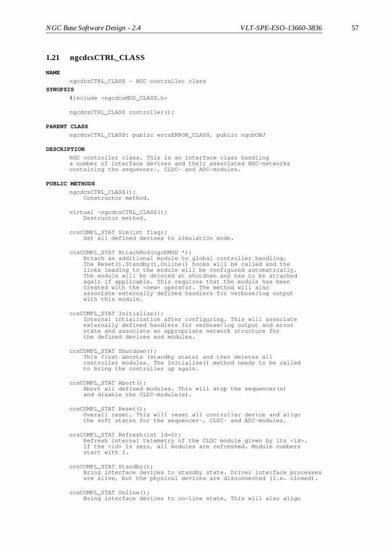
NGC Base Software Design - 2.4 VLT-SPE-ESO-13660-3836 57
1.21 ngcdcsCTRL_CLASS
NAME
ngcdcsCTRL_CLASS - NGC controller class
SYNOPSIS
#include <ngcdcsMOD_CLASS.h>
ngcdcsCTRL_CLASS controller();
PARENT CLASS
ngcdcsCTRL_CLASS: public eccsERROR_CLASS, public ngcbOBJ
DESCRIPTION
NGC controller class. This is an interface class handlinga number of interface devices and their associated NGC-networkscontaining the sequencer-, CLDC- and ADC-modules.
PUBLIC METHODS
ngcdcsCTRL_CLASS(); Constructor method.
virtual ~ngcdcsCTRL_CLASS(); Destructor method.
ccsCOMPL_STAT Sim(int flag); Set all defined devices to simulation mode.
ccsCOMPL_STAT AttachMod(ngcbMOD *); Attach an additional module to global controller handling. The Reset(),Standby(),Online() hooks will be called and the links leading to the module will be configured automatically. The module will be deleted at shutdown and has to be attached again if applicable. This requires that the module has been created with the <new> operator. The method will also associate externally defined handlers for verbose/log output with this module.
ccsCOMPL_STAT Initialize(); Internal intialization after configuring. This will associate externally defined handlers for verbose/log output and error state and associate an appropriate network structure for the defined devices and modules.
ccsCOMPL_STAT Shutdown(); This first aborts (standby state) and then deletes all controller modules. The Initialize() method needs to be called to bring the controller up again.
ccsCOMPL_STAT Abort(); Abort all defined modules. This will stop the sequencer(s) and disable the CLDC-module(s).
ccsCOMPL_STAT Reset(); Overall reset. This will reset all controller device and align the soft states for the sequencer-, CLDC- and ADC-modules.
ccsCOMPL_STAT Refresh(int id=0); Refresh internal telemetry of the CLDC module given by its <id>. If the <id> is zero, all modules are refreshed. Module numbers start with 1.
ccsCOMPL_STAT Standby(); Bring interface devices to standby state. Driver interface processes are alive, but the physical devices are disconnected (i.e. closed).
ccsCOMPL_STAT Online(); Bring interface devices to on-line state. This will also align

58 NGC Base Software Design - 2.4 VLT-SPE-ESO-13660-3836
the soft states for the sequencer-, CLDC- and ADC-modules and call the appropriate on-line hooks. The driver interface processes are alive and all physical devices are connected (i.e. opened). If a device was disconnected before (i.e. was in standby- or off-state), a hardware reset is performed on this device and the NGC- network is (re-)enabled afterwards. If the <check> flag is set, then system integrity checks are performed before going on-line.
ccsCOMPL_STAT Off(); Bring interface devices to off-state. All physical devices are disconnected and driver interface processes are not alive.
void Shutdown(); Shutdown all controller modules. This will delete all created objects for the sequencer-, CLDC- and ADC-modules.
ngcbNET *Network(int instance); Return pointer to the NGC network structure associated with a device specified by its instance number. If no network is associated to the given interface instance, a NULL pointer is returned.
ccsCOMPL_STAT Enable(); Enable all networks associated with the defined interface devices.
ccsCOMPL_STAT ReadAddr(ngcbIFC *dev, ngcb_route_t route, int address, int *buffer, int size); Reads size words from the given device address into buffer. The ngcb_route_t structure contains the following elements:
int numHdr; - Number of headers to target including the terminating <0x2> int hdr[ngcbMAX_MOD]; - Array of headers including the terminating <0x2>
ccsCOMPL_STAT WriteAddr(ngcbIFC *dev, ngcb_route_t route, int address, int *buffer, int size); Writes size words from buffer to the given device address. The ngcb_route_t structure contains the following elements:
int numHdr; - Number of headers to target including the terminating <0x2> int hdr[ngcbMAX_MOD]; - Array of headers including the terminating <0x2>
ccsCOMPL_STAT WriteBuffer(ngcbIFC *dev, int *buffer, int size); Writes a formatted buffer to the given interface device. The format of the buffer is: <hdr1 hdr2 ... hdrN address data1 data2 ...>
PUBLIC DATA MEMBERS
ngcb_es_t errStateHandler; - External error-state handler of type:
void myHandler(char *erms, ngcbIFC *module)
int ioError; - Indicates that the preceeding transaction caused an i/o error on one of the interface devices(generally the connection should be reset in that case).
ngcbIFC *dev[ngcdcsCTRL_MAX_DEV]; - Controller interface devicesint numDev; - Number of interface devices
ngcdcsCLDC_CLASS *cldc[ngcdcsCTRL_MAX_CLDC]; - CLDC modulesint numCldcMod; - Number of CLDC modulesint cldcRef; - CLDC reference module
ngcdcsSEQ_CLASS *seq[ngcdcsCTRL_MAX_SEQ]; - Sequencer modulesint numSeqMod; - Number of sequencer modules
NGC Base Software Design - 2.4 VLT-SPE-ESO-13660-3836 59
int seqRef; - Sequencer reference module
ngcdcsADC_CLASS *adc[ngcdcsCTRL_MAX_ADCMOD]; - ADC modulesint numAdcMod; - Number of ADC modulesint adcRef; - ADC reference module
RETURN VALUES
If not specified differently, all functions return SUCCESSin case of success. Otherwise FAILURE is returned and anerror is added to the error-stack.
SEE ALSO
ngcbOBJ(4), ngcbIFC(4), ngcbNET(4), ngcbMOD(4), ngcdcsCLDC_CLASS(4),ngcdcsSEQ_CLASS(4), ngcdcsADC_CLASS(4)

60 NGC Base Software Design - 2.4 VLT-SPE-ESO-13660-3836