Embed Size (px)
Citation preview

P#
87
1
Very Compact Integration of an Ultra-Low
Vibration Platform for Space Cryocoolers
Using Miniature High Frequency Actuators
G. Aigouy1, J. Butterworth1, J-C. Rey1, C. Benoit2, P. Lamy3
1 Air Liquide Advanced Technologies, 38600 Sassenage, France2 Cedrat Technologies S.A., 38246 Meylan, France3 SMAC, 83079 Toulon, France
ABSTRACT
Air Liquide advanced Technologies in collaboration with Cedrat Technologies and SMAC has
performed a study of a compact vibration control platform for mechanical cryocoolers. This solu-
tion has been proposed as an alternative approach to cryocooler integration with respect to sus-
pended systems that must be mechanically locked during the launch phase. This system allows
significant reduction of the platform’s physical size and mass.
The platform filters vibrations generated by the cryocoolers above 150¶Hz using passive dissi-
pation in metallic or elastomeric mounting blocks. Vibration generated by the cryocoolers below
150¶Hz is suppressed through a vibration cancellation algorithm that balances the opposed piston
compressor (piston axis) and by miniature high frequency actuators for the other axes.
An overview of the system is presented together with results of initial tests
INTRODUCTION
Over the last 12 years, Air Liquide Advanced Technologies (AL.AT) has developed and ma-
tured pulse tube cryocoolers for both Earth Observation and Space Science programs.1-5 The devel-
opments began with the 80K Miniature Pulse Tube Cryocooler (MPTC) before moving to the
40 - 50¶K range with the large pulse tube cooler (LPTC), and now reach the 10 - 20¶K temperature
range.
The LPTC cooler has been selected for flight on two space programs with more than a dozen
flight coolers scheduled to be delivered in the next few years. The LPTC is currently in the process
of final qualification in the framework of a national program and will also provide cooling for the
European Meteosat Third Generation (MTG) program.
A significant part of this development effort has been dedicated to performance refinement,
system level optimization, and integration improvements with respect to induced micro-vibrations.
The MTG project has been a challenging milestone in order to achieve the lowest induced vibration
level possible, for which a dedicated integration platform has been studied, and proposed as an
alternative approach to existing suspended systems with launch locking devices. As part of the final
proposition for the MTG project, an ultralow induced vibration integration platform has been stud-
ied and partially tested, which combines the use of passive isolation dampers above 150¶Hz and
531Cryocoolers 17, edited by S.D. Miller and R.G. Ross, Jr.©¶International Cryocooler Conference, Inc., Boulder, CO, 2012

P#
87
2
Figure 1. Proposed MTG ultra-low vibration integration platform
Figure 2. Compact integration of theplatform compared to classical integration
Figure 3. LPTC Cooler equippedwith miniature actuators
active miniature piezoelectric actuators for low frequencies. This new approach allows a fully multi
axis control to reduce the vibrations, with a control effort reduced to low frequencies only, and with
very little additional power consumption. The platform is composed exclusively of flight proven
components and materials, for the actuators, and elastomeric materials, which gives a high level of
maturity to the proposed solution. The implementation of the actuator’s drivers inside the elec-
tronic has been studied and assessed in terms of electrical consumption and reliability inside the
MTG CDE.
This approach uses active balancing of the compressor moving masses along the piston axis,
described previously,1,2 and piezoelectric actuators for the other two compressor axes and the cold
head.
PROPOSED MTG PLATFORM DESIGN
The achieved final plate form design, proposed for MTG weighs around 40¶kg including two
redundant LPTC coolers, and associated drive electronics, without any additional launch locking
device required (Figures 1 & 2).
The multi-axis vibration control is achieved by a combination of passive isolation dampers that
become effective for frequencies higher than 150¶Hz, and active control using the existing compres-
sor moving masses balancing method for the piston’s axis, and external miniature actuators for the
compressor and cold finger transverse axes (Figure 3).
The achievable induced vibration level (resultant of compressor plus cold finger) has been
analyzed with finite element analyses based on the achieved control performance of the actuators,
and the theoretical isolation performance of the dampers. The expected performance, shown in
Figure 4, is a maximum level of 100¶mN over the full frequency range up to 1000¶Hz and lower than
50¶mN in the frequency range of 50¶Hz-460¶Hz (8 harmonics of the LPTC drive frequency at 57.5¶Hz).
532 CRYOCOOLER INTEGRATION TECHNOLOGIES

P#
87
3
Figure 7. In flight interface force measurement with momentum interpretation
Figure 4. Theoretical achievable induced vibration performances (resultant)
Figure 5. Collocated integration ofthe miniature actuators on the compressorinterface load washers
Figure 6. Integration of the miniatureactuators on the cold finger resultant vibrationsources
The complete system performance could not be tested as the proposed platform assembly has
not been retained by the MTG project. However, the complete system has been analyzed for launch
loads to demonstrate the suppression of the launch locking device.
MINIATURE PIEZOELECTRIC ACTUATORS
The miniature actuators have been integrated onto the compressor and the cold finger as shown
in Figures 5 to 7. On the compressor the actuators have been collocated with the interface load
washers which provide the in flight force information by interpreting the moment measurement in
the in-plane axes (FY and FX) and by a direct measurement in the out-of-plane axis (FZ). On the
cold finger the actuators have been located onto the gas momentum geometrical sources, as no
mechanical moving part generates vibration on pulse tube type cold fingers.
533UTRA-LOW VIBRATION USING MINIATURE ACTUATORS

P#
87
4
Figure 8. Proposed feed forward control scheme
The actuators selection and integration have been undertaken in partnership with CEDRAT
which has developed piezoelectric actuators for space applications; these are flight proven on sev-
eral missions. The inherent good balancing of the compressor and the inherent low vibration level
of the pulse tube type cold finger has allowed selecting small size actuators providing a proof mass
force up to 200¶mN, with a few grams mass attached, with a very small electrical consumption, and
a very compact design. The major advantage of miniature actuators is the very high resonance
frequency above 1000¶Hz which makes their use compatible with the launch sine and random vibra-
tion environment without any locking required.
The existing frequency domain control method currently applied onto the compressor moving
masses has been successfully tested on the actuators, and has been considered as a backup method
for MTG. A significant demonstration effort has been realized for the MTG project to demonstrate
the performance and advantages of feed forward real time control methods which are not currently
used for coolers on space applications compared to state of the art frequency domain optimization
methods. Time domain tests have been realized to assess the achievable control performance and to
propose the most appropriated control scheme. The final proposed control approach (shown in
Figure 8) is based on a combination of time domain adaptive filtering and actuator differential
phasing optimization. The advantage of adaptive filtering methods is the possibility to operate the
control on a degraded mode without available vibration measurements once the filter coefficients
have been defined.
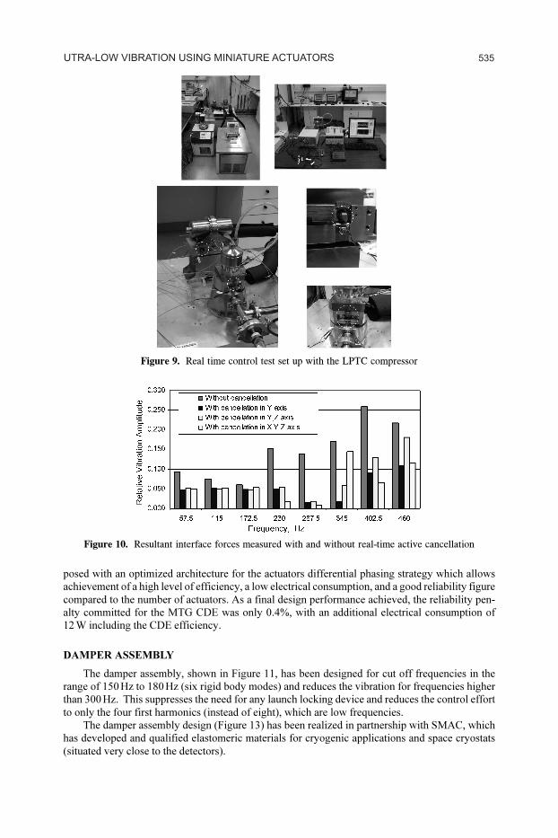
Figure 9 illustrates the test setup, while Figure 10 shows the control performance achieved
with a classical real time control approach (adaptive filtering not tested yet) on the test set up of
Figure 9. The result noted as “without cancellation” means only with the compressor moving mass
balancing control (resultant over all axes).
ACTUATOR DRIVERS IMPLEMENTATION INSIDE THE CDE
The actuator driver implementation inside the LPTC Cooler Drive Electronic (CDE) has been
assessed in terms of electrical consumption cost and reliability. A dedicated design has been pro-
534 CRYOCOOLER INTEGRATION TECHNOLOGIES
P#
87
5
Figure 9. Real time control test set up with the LPTC compressor
posed with an optimized architecture for the actuators differential phasing strategy which allows
achievement of a high level of efficiency, a low electrical consumption, and a good reliability figure
compared to the number of actuators. As a final design performance achieved, the reliability pen-
alty committed for the MTG CDE was only 0.4%, with an additional electrical consumption of
12¶W including the CDE efficiency.
DAMPER ASSEMBLY
The damper assembly, shown in Figure 11, has been designed for cut off frequencies in the
range of 150¶Hz to 180¶Hz (six rigid body modes) and reduces the vibration for frequencies higher
than 300¶Hz. This suppresses the need for any launch locking device and reduces the control effort
to only the four first harmonics (instead of eight), which are low frequencies.
The damper assembly design (Figure 13) has been realized in partnership with SMAC, which
has developed and qualified elastomeric materials for cryogenic applications and space cryostats
(situated very close to the detectors).
Figure 10. Resultant interface forces measured with and without real-time active cancellation
535UTRA-LOW VIBRATION USING MINIATURE ACTUATORS

P#
87
6
Figure 11. High frequency passive isolation assembly
Figure 12. Theoretical dampers isolation performance (resultant)
Figure 13. Elastomeric damper designs from SMAC with space qualified materials
The final design of the damping assembly frequency coverage from both active and passive
vibration control systems is summarized in Figure 14.
REFERENCES
1. Trollier, T. et al., “Status of Air Liquide Space Pulse Tube Cryocoolers,” Cryocoolers 15, ICC Press,
Boulder, CO (2009), pp. 115-123.
2. Trollier, T. et al, “Air Liquide space pulse tube cryocoolers and associated cooler drive electronics,”
Proceedings of ICEC 22-ICMC 2008, (2009), pp. 781-86.
536 CRYOCOOLER INTEGRATION TECHNOLOGIES

P#
87
7
Figure 14. Frequency coverage of the platform
3. Trollier, T. et al, “Design of Large Heat Lift 40 to 80 K Pulse Tube Cryocooler for Space Applica-
tions,” Cryocoolers 14, ICC Press, Boulder, CO (2007), pp. 75-82.
4. Tanchon, J. et al., “Air Liquide Space Pulse Tube Cryocoolers,” Adv. in Cryogenic Engineering, vol.
53A, Amer. Institute of Physics, Melville, NY (2008), pp. 506-513.
5. Tanchon, J. et al., “20–50 K and 40–80 K pulse tube coolers: Two candidates for a low temperature
cooling chain,” Cryogenics, vol. 50 (2010), pp. 55-60.
537UTRA-LOW VIBRATION USING MINIATURE ACTUATORS