Embed Size (px)
Citation preview

• BEL
Vertical Spindle Moulder
Instruction Manual
www.wad
kin.co
m
info@
wadkin
.com

BE CAREFUL THIS MACHINE CAN BE DANGEROUS
IF IMPROPERLY USED
Always use guards. Keep clear until rotation has ceased.
Always operate as instructed and in accordance with good practice.
Read instruction manual before installing, operating or maintaining machine.
Manufactured by: A L Dalton Ltd Crossgate Drive Queens Drive Ind Est Nottingham
-I--!!! ~~? ;~~~ .
NG21 LW United Kingdom
Telephone Number: 0870 850 9111 Fax Number: 0870 240 0575
Website: www.wadkin.com Email: [email protected]
MODEL TYPE:
SERIAL NO:
VOLTS: HP:
015
YEAR:
PH: HZ:
www.wad
kin.co
m
info@
wadkin
.com
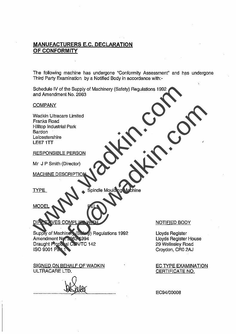
MANUFACTURERS E.C. DECLARATION OF CONFORMITY
The following machine has undergone "Conformity Assessment" and hflS undergone Third Party Examination by a Notified Body in accordance with:-
Schedule IV of the Supply of Machinery (Safety) Regulations 1992 and Amendment No. 2063
COMPANY
Wadkin Ultracare Limited Franks Road Hilltop Industrial Park Bardon Leicestershire LE671TT
RESPONSIBLE PERSON
Mr J P Smith (Director)
MACHINE DESCRIPTION
TYPE
MODEL
Spindle Moulding Machine
BEL
DIRECTIVES COMPLIED WITH
Supply of Machinery (Safety) Regulations 1992 Amendment No. 20631994 Draught Proposal CENITC 142 ISO 9001 Part 1
SIGNED ON BEHALF OF WADKIN UL TRACARE LTD.
NOTIFIED BODY
Lloyds Register Lloyds Register House 29 Wellesley Road Croydon, CRO 2AJ
i
EC TYPE EXAMINATION CERTIFICATE NO.
EC94/00008
www.wad
kin.co
m
info@
wadkin
.com
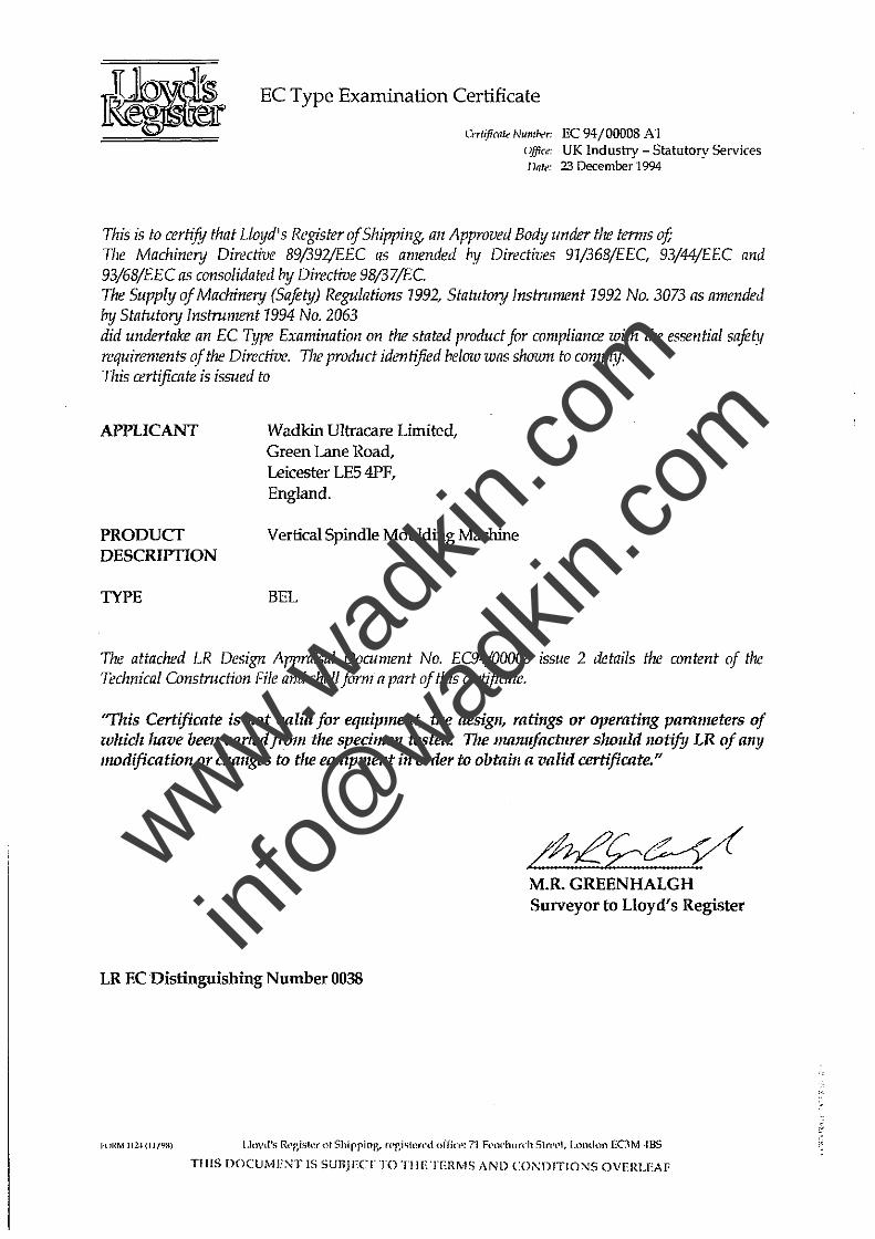
EC Type Examination Certificate
CI·rt~fi(i1le Num"r'r; EC 94/00008 A1 "!fi'" UK Industry - Statutory Services J )fife: 23 December 1994
This is to certify that Lioyd's Register of Shipping, an Approved Body under the terms of; The Machinenj Directive 89/392/EEC as amended by Directives 91/368/EEC 93/44/EEC and 93/68/EEC as consolidated by Directive 98/37jEC. The Supply oj Machinery (Saftty) RegulatiO/ls 1992, Statutory instnm1l!nt 1992 No. 3073 as amended by Statutory ins/ru1111!nt 1994 No. 2063 did undertake an EC Type Examination 011 the stated product for compliance with the essential safety requirements ~f the Directive. The product identified below was shown to comply. This certificate is issued to
APPLICANT
PRODUCT DESCRIPTION
TYPE
Wadkin Ultracare Limited, Green Lane Road, Leicester LE54PF, England.
Vertical Spindle Moulding Machine
BEL
The attached LR Desigrz Appraisal Document No. EC94/00008 issue 2 details the content of the Technical Constmction File and shall forma part of this certificate.
"TIzis Certificate is not valid for eqllipment, the design, ratings or operating parameters of which /ulVe been varied from the specimen tested. TIle mamljacblTer sJwllld notify LR of any modification or changes to the equipment in order to obtain a valid certificate."
LR EC Distinguishing Number 0038
1"(IRM I 12·1 tll/",a)
/n,ef:C:--Y( M.R. GREENHALGH Surveyor to Lloyd's Register
TillS DOCUMENT IS SUllJECT TO TilE TERMS AND CO;\;D1TIONS OVERLEAF
www.wad
kin.co
m
info@
wadkin
.com
PREFACE
IMPORTANT
It is our policy' and that of our suppliers to constantly review the design anCi capacity of our products. With this in mind we would remind our customers that while the dimensions and performance data contained herein are correct at the time of going to press1 it is possible that due to the incorp.0ratio.n of the latest develOpments to enhance. performance, dimensions and suppliers may vary from those illustrated.
This manual is written as a general guide. A typical machine is shown to illustrate the mam features. For reason of clarity certain guards1 safety devices and machine parts may not be shown on pan:icular illustrations but MUST be fixeo to the machine, correctly set and working before operating
Failure to comp'ly with instructions in this manual may invalidate the guarantee
www.wad
kin.co
m
info@
wadkin
.com
HEALTH AND SAFETY
The CE mark on this machine signifies that an EC Declaration of Conform~y is drawn up indicating that the machine is manufactured in accordance with the Essential Health and Safety Requirements of the 'Supply of Machinery (Safety) Regulations 1992'.
The 'requirements for supply of relevant machinery' in the General Requirements of the Regulations are not only that the machine satisfies the relevant essential health and safety requirements, but also that 1he manufacturer ....... carries out the necessary research or lests on components, fittings or the complete machine to determine whether by its design or construction the machine is capable of being erected and put into service safely'.
Persons who install this machine have duties under the 'Provision and Use of Work Equipment Regulations 1992'. An indication of these duties is given in the following extracts, but the user should be familiar with the full implications of the regulations.
REGULATION 5 requires that:
Every employer shall ensure that work equipment is so constructed or adapted as to be suitable for the purpose for which it is used or provided.
In selecting work eqUipment, every employer shall have regard to the working condHions and to the risks to heatth and safety of persons which exist in the premises or undertakings in which that work equipment is to be used and any add~ional risk posed by the use of that work equipment.
Every employer shall ensure that work . . equipment is used only for the operations for which, and under cond~ions for which, It is su~able.
In this regulation 'suHable' means suitable in any respect Which It is reasonably foreseeable will affect heatth or safety of any person.
The Provision and Use of Work Equipment Regulations also include requirements as follows.
regulation 6 - maintenance,
regulation 7 - specific risks,
regulation 8 . information and instructions,
regulation 9 . training.
Note:-
Attention is drawn to those requirements of the 'Woodworking Machines Regulations 1974' which are not replaced by the Supply of Machinery (Safely) Regulations or other, eg; Regulation 13 of the Woodworking Machinery Regulation, - 'Training', still applies.
Whilst the prime duty for ensuring health and safety rests with employers, employees too have legal duties, particularly under sections 7 and 8 of the Health and Safety at Work Act. They includ e;
taking reasonable care for their own health and safety and that of others who may be affected by what they do or don·t do;
co-operating with their employer on health and safety;
not intertering with or misusing anything provided for their health, safety and welfare.
These duties on employees have been supplemented by regulation 12 of the Management of Health and Safety at Work Regulations 1992. One of the new requirements is that employees' should use correctly all work Hems provided by their employer in accordance with their training and the instructions they receive to enable them to use the. items safely.
www.wad
kin.co
m
info@
wadkin
.com
Noise
Noise levels can vary widely from machine to machine depending on the conditions of use. Persons exposed to high noise levels. even for a short time, may experience temporary partial hearing loss and continuous exposure to high levels can result in permanent hearing damage.
The Noise at Work Regulations 1989 place legal duties on employers to prevent damage to hearing.
There are three action levels 01 noise defined in regulation 2;
the first actionlevel:-
a dally. personal noise exposure (LEP.') of 85dB(a)
the second action level:-
a daily personal noise exposure (LEP. ,) of 90dB(A)
the peak action level
a peak sound pressure of 200 pascals (140dB re 20pa)
The exposure level is obviously influenced by the emission level of all the equipment in use.
Emission levels for machines are provided in the particular machine instruction book.
These levels are measured in accordance with ISO 7960 under certain specified test conditions, they do not necessarily represent the highest noise level, which is influenced by many factors, eg number of spindles in operation, type and condition of workpiece, spindle speeds etc.
For regulations and information on relevant personal protective equipment i.e., ear defenders, employers should refer to the Personal Protective Equipment at Work Regulations 1992.
Dust
Wood dust can be harmful to health by inhalation and skin contact and concentrations of small panicles in the air can form an explosive mixture.
The Control of Substances Hazardous 10 Heaith Regulations (COSHH) 1989 place legal duties on employers to ensure that:
the exposure of his employees to substances hazardous to health is either prevented or, where this is not reasonably practicable, adequately controlled.
..... adequate control to exposure of employees to a substance hazardous to health shall be secured by measures other than the provision of personal protective equipment.
where the measures taken in accordance with the paragraph above do not prevent or provide adequate control ai, exposure to substances hazardous to the health of employees, Ihen, in addition 10 taking those measures, the employer shall provide those employees with such suilable personal protective equipment as will adequately control their exposure to substances hazardous 10 health.
Instructions for Use
Machinery manufacturers are required by the Supply of Machinery Safety Regulations to provide comprehensive 'Instructions for Use' of equipment, it is important that this information is transmitted to the person using the machine. www.w
adkin
.com
info@
wadkin
.com

IMPORTANT
SAFETY PROCEDURES AND CONSIDERATIONS
To ensure safe working conditions, persons operating and assisting with the operation of this machine must ensure that they read and fully understand the instructions given within this manual and have received sufficient training in the use of the machine and the safety aspects to be observed.
Note:- Persons under the age of 18 years must not operate the machine except during a course of training under the supervision of a trained operator.
A) POINTS TO NOTE BEFORE OPERATING OR ASSISTING WITH THE OPERATION OF THE MACHINE
1) You have read and understood the operation and safety aspects of the machine and have been checked out by a qualified supervisor.
2) The machine is supplied with full safeguarding. The machine shall not be operated unless .the safeguardings are in position and functional.
3) Cutters/blades are the correct type, suitable for the machine and working conditions, rotate in the correct direction of cut, are sharp and correctly fitted.
4) Correct spindle and speeds are selected for the cutter equipment and working conditions.
5) Loose clothing is either removed or securely fastened back and jewellery removed.
6) Adequate working space and lighting is provided.
7) All dust extraction equipment is switched on, prope~ly adjusted and working adequately.
8) The machine is securely installed (refer to installation section within this manual).
9) The machine should only be used for cutting wood or materiars with physical and technological characteristics similar to wood, and for which the chip or particle removal process is similar.
www.wad
kin.co
m
info@
wadkin
.com
8) DURING MACHINING:-
1) Wear suitable protective clothing e.g., approved eye protection, ear defenders and dust mask. Gloves shall be worn when handling sharp edged saws.
2) Stop the machine using the emergency stop or at the mains' isolator before making adjustments, cleaning or carrying out maintenance.
3) Keep the floor area around the machine clean and free from wood refuse. Do not allow the floor around the machine to become slippery.
4) Stop the machine and report immediately to a person in authority any actual or potential malfunction or operator hazard. Do not attempt to repair or rectify the machine unless qualified and authorised to do so.
5) The operator must not leave the machine running whilst unattended.
6) Never by pass interlocks.
7) A push stick or handled push block must be used to feed the trailing end of a workpiece past the cutting head.
8) When ripping never stand directly behind the material.
WARNING:-
Failure to observe correct operating procedures prior to and during operation of this machine can result in severe injury.
DO NOT attempt to operate the machine while under the influence of anything that reduces your alertness. www.w
adkin
.com
info@
wadkin
.com
CONTENTS
SECTION 1 GENERAL INFORMATION Page No
General description General machining practices Noise Emission values Working areas Foundation dimensions Tooling requirements Machine specification Electrical diagram
SECTION 2 INSTALLATION
Unloading Unpacking Cleaning Location and foundation Supplies and services
1-1 1-1 1-3 1-4 1-5 1-7 1-9 1-11
2-1 2-1 2-1 2-1 2-2
SECTION 3 OPERATING INSTRUCTIONS
Safety and safety devices 3-1 Machine controls 3-2 False fences 3-2 Changing loose work spindle and/or cutter 3-5 Machine adjustment - Top guard opening 3-7
Top cover/shaw guard 3-7 Straight fence adjustment 3-7 Spindle speed change 3-9 Vertical spindle adjustment 3-9 Table rings removal/replacement 3-10 Ring fence 3-10 www.w
adkin
.com
info@
wadkin
.com
pep ~
1~lm -----------------------------------------------
SECTION 4 MAINTENANCE
Scheduled maintenance - General information Weekly information Monthly information
Drive belt tensioning/adjustment and replacement Brake motor - disc replacement Approved lubricants
SECTION 5 SPARES
Fence assembly Fence guard assembly Table rings Spindle rise and fall Spindle assembly Motor mounting and belt tensioning Loose top piece Ring fence Side tables and support rails
Page No
4-1 4-1 4-1 4-1 4-2 4-5
5-3 5-5 5-7 5-9 5-11 5-13 5-15 5-17 5-19
www.wad
kin.co
m
info@
wadkin
.com
15
14 ~
BEL
13-==PB~~'\ 12 11
10
1
rG~
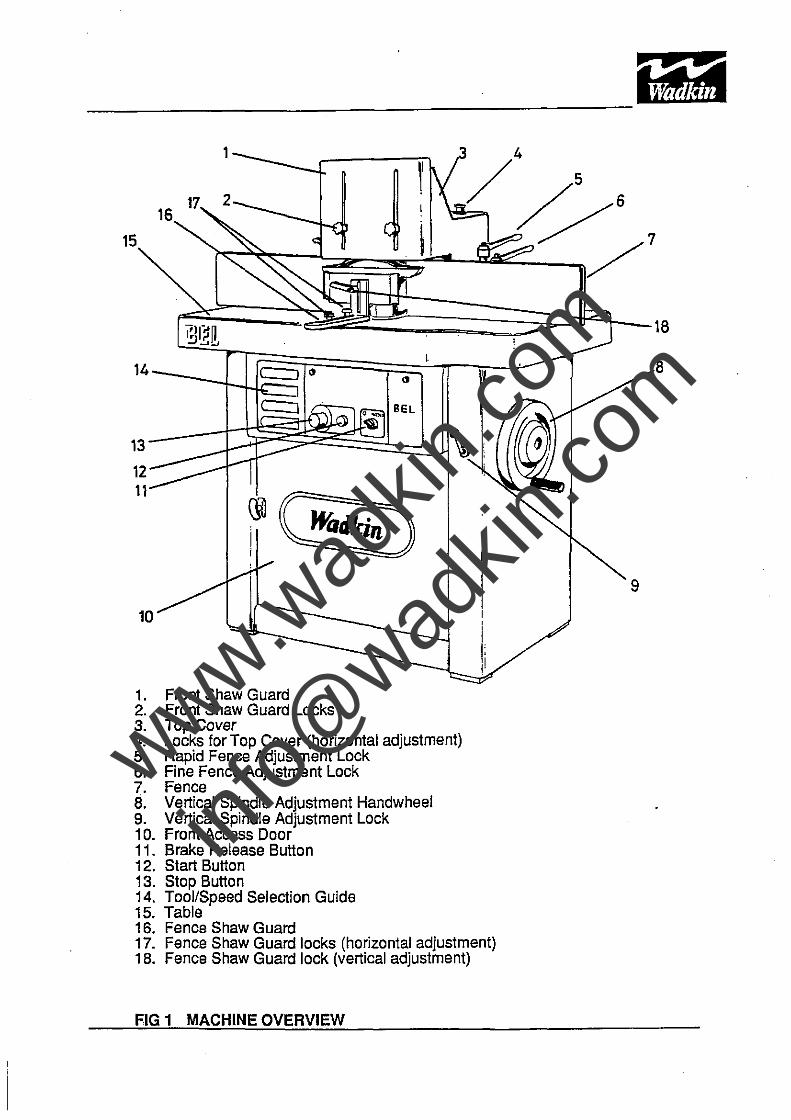
1. Front Shaw Guard 2. Front Shaw Guard Locks 3. Top Cover 4. Locks for Top Cover (horizontal adjustment) 5. Rapid Fence Adjustment Lock 6. Fine Fence Adjustment Lock 7. Fence 8. Vertical Spindle Adjustment Handwheel 9. Vertical Spindle Adjustment Lock 10. Front Access Door 11. Brake Release Button 12. Start Button 13. Stop Button 14. Tool/Speed Selection Guide 15. Table 16. Fence Shaw Guard
! , i I: '1 !'
17. Fence Shaw Guard locks (horizontal adjustment) 18. Fence Shaw Guard lock (vertical adjustment)
FIG 1 MACHINE OVERVIEW
8
9
www.wad
kin.co
m
info@
wadkin
.com
SECTION 1 GENERAL INFORMATION
General Description
The Wadkin BEL Spindle Moulder is a hand fed machine with a fixed precision ground, cast iron work table.
Protruding through the table is. a single vertical spindle with an interchangeable loose top piece. These optional top pieces allow for a variety of tooling to be used with a quick change over time.
An automatic brake motor with coned drive pulley is located beneath the table. This motor, via a toothed 'V' belt, provides drive to the coned spindle pulley.
Vertical spindle movement is achieved by rotation of the large hand wheel located on the side of the machine. Fully adjustable guards and fences ensure accurate and safe machining.
General Machining Practices
This machine has been approved for machining wood, plastics and composites. Other materials with physical and technological characteristics similar to wood and for which the chip or particle removal process is similar may be machined but only after consultation and approval of Wadkin Plc.
The correct guarding must always be used and should be adjusted to suit individual machine set ups. Correctly positioned guards prevent access to rotating components when machining.
The type of cutterblock, the cutter projection and the height at which the block is set will determine the minimum size of the hole in the table. Select the loose table rings so as to
. give the smallest possible hole and thus reducing the risk of the work piece dipping and catching the edge as It passes over the gap.
When machining a series of identical components the following piece can be used to feed the previous one but a push stick or handled push block must be used for the final piece.
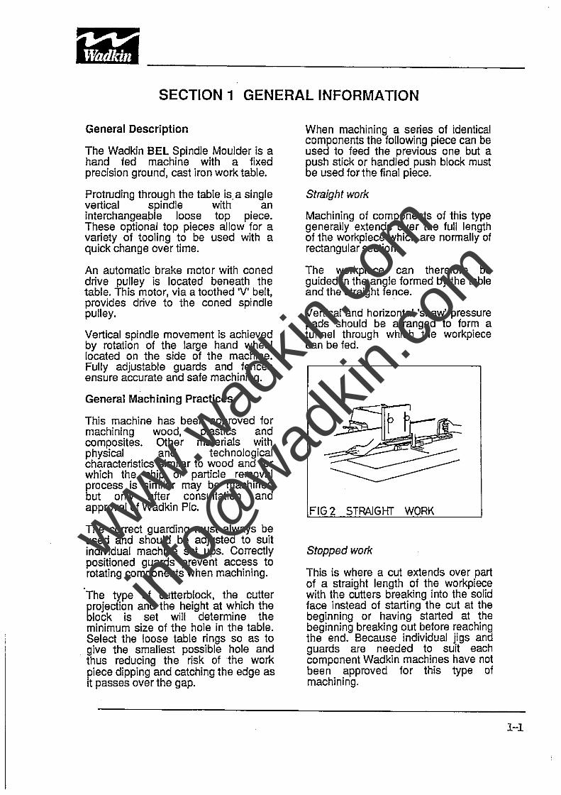
Straight work
Machining of components of this type generally extends over the full length of the workpiece which are normally of rectangular section.
The workpiece can therefore be guided in the angle formed by the table and the straight fence.
Vertical and horizontal 'shaw' pressure pads should be arranged to form a tunnel through which the workpiece can be fed.
FIG 2 STRAIGI-IT WORK
Stopped work
This is where a cut extends over part of a straight length of the workpiece with the cutters breaking into the solid face instead of starting the cut at the beginning or having started at the beginning breaking out before reaching the end. Because individual jigs and guards are needed to suit each component Wadkin machines have not been approved for this type of machining.
1-1
www.wad
kin.co
m
info@
wadkin
.com
-----------------------------------------------
1-2
Bevel cutting
Wadkin do not supply special jigs or a canting table for the spindle moulders and therefore a profile cutterblock must be used to produce bevels.
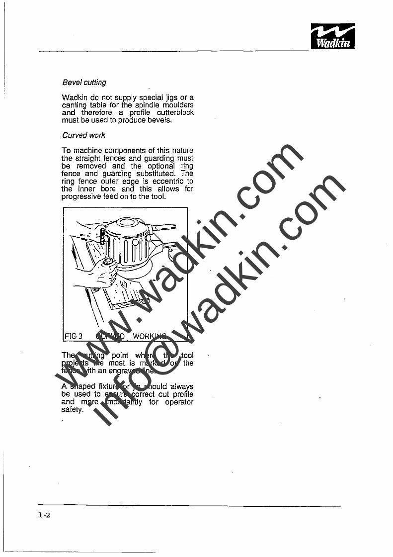
Curved work
To machine components of this nature the straight fences and guarding must be removed and the optional ring fence and guarding substituted. The ring fence outer edge is eccentric to the inner bore and this allows for progressive feed on to the tool.
FIG 3 CURVED. WORKING
The cutting point where the tool projects the most is marked on the fence with an engraved line.
A shaped fixture or jig should always be used to ensure correct cut profile and more importantly for operator safety.
Jii! •• ~
111&111
www.wad
kin.co
m
info@
wadkin
.com
NOISE EMISSION VALUES
Machine criteria
The BEL spindle moulder was assessed for noise emissions as a free standing machine on a concrete floor, not bolted down and not mounted on any vibration dampening. . Flexible piping connected the machine to the main dust extraction.
Material criteria
Material :- Three layer particle board
Moisture content:- 6-10% Material width :- 800mm Material length :- 800mm Material thickness :-16mm
Machine cutting criteria
Tooling of diameter 125mm, 25mm wide and with two knifes was fitted to the machine s'pindle. Timber was hand fed into the cutting area at a rate of between 4 and 8 meters per minute with the spindle rotating at 6000 r.p.m. Cutting depth was set at 10mm.
The figures quoted in the noise chart are Emission levels and are not necessarily safe working levels. Whilst there is a correlation between Emission levels and exposure levels, this cannot be used reliably to determine whether or not further precautions are required. Factors that Influe nce the actual level of exposure to the work face include the duration of exposure, the characteristics of the work room, other sources of dust and noise i.e., the number of machines on other adjacent processes. Also the permissible exposure levels can vary from country to country. This information however, will enable the user of the machine to make a better evaluating of the hazard and risk.
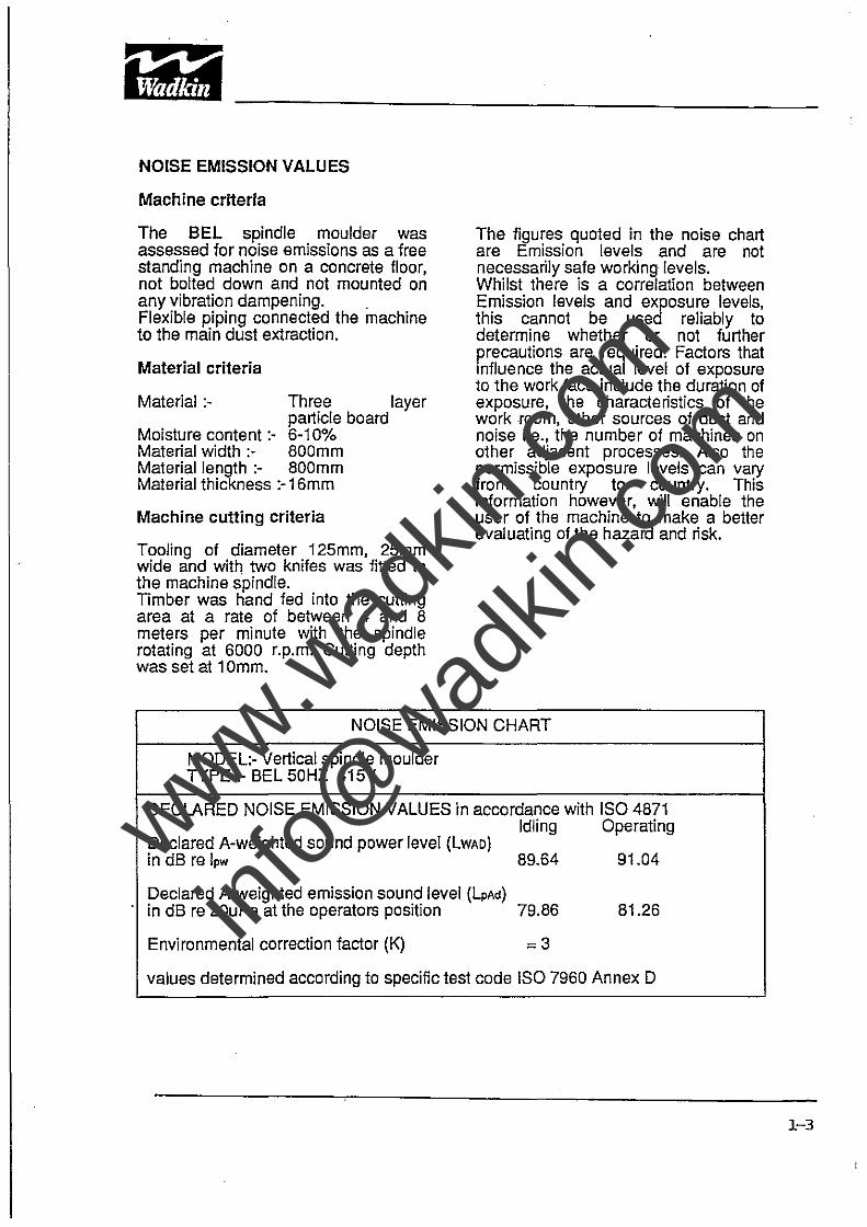
NOISE EMISSION CHART
MODEL:- Vertical spindle moulder TYPE :- BEL 50HZ 415V
DECLARED NOISE EMISSION VALUES in accordance with ISO 4871 Idling Operating
Declared A-weighted sound power level (LWAO) in dB re Ipw 89.64 91.04
Declared A-weighted emission sound level (LpAd) in dB re 20uPa at the operators position 79.86 81.26
Environmental correction factor (K) ~3
values determined according to specific test code ISO 7960 Annex D
1-3
www.wad
kin.co
m
info@
wadkin
.com
~. #~
I~"!t)~ -----------------------------------------------
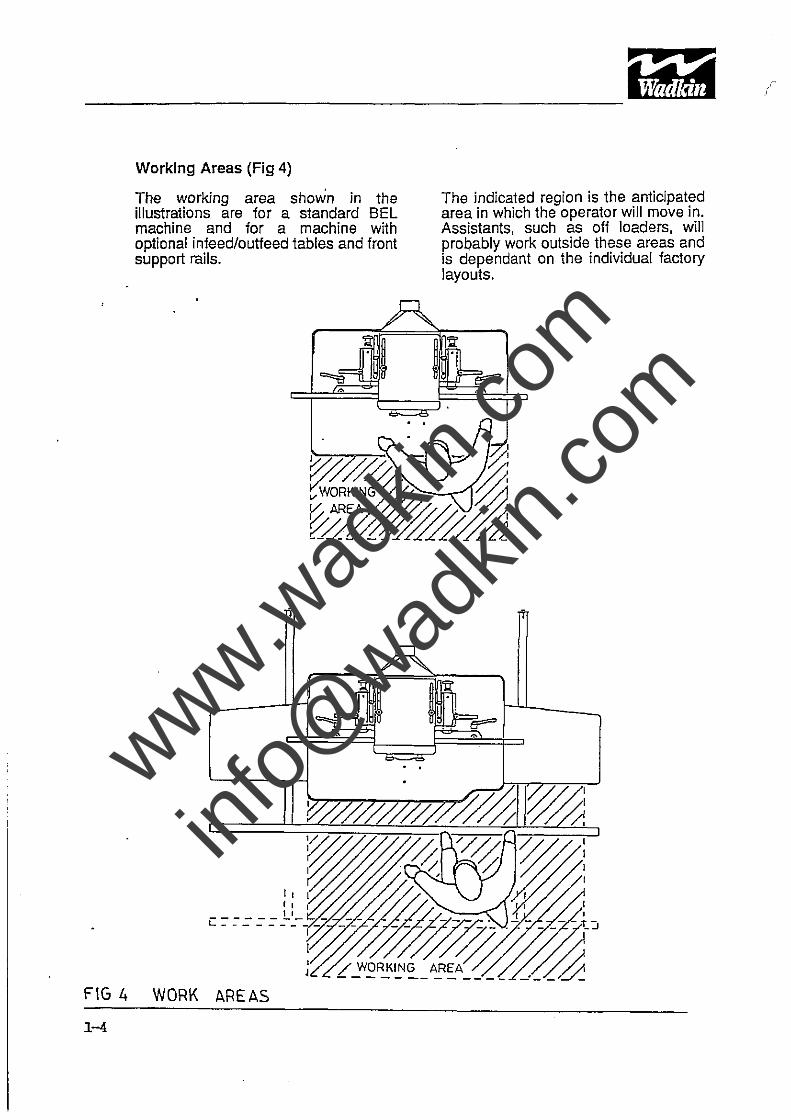
Working Areas (Fig 4)
The working area shown in the illustrations are for a standard BEL machine and for a machine with optional infeed/outfeed tables and front support rails.
I,
" I , I c:-:-:::: ~ _-~ __ -I
I
'll: I' .
FIG 4 WORK AREAS
1-4
, ,
The indicated region is the anticipated area in which the operator will move in. Assistants, such as off loaders, will probably work outside these areas and is dependant on the individual factory layouts.
www.wad
kin.co
m
info@
wadkin
.com
l
873
'11!'
~~~~ 0
ml ~. m l" 0
@=I)
J1l liJ
1485
565
930
150 ~ ____ I
i i -
1J .cJ.,
f---- ff 0
--- b.. 0
~
-i1 I i
.
~
N N
0') ~ 11 >< c
;;
~ o z o .. :a
-j ! '-.• _ .. -1 ____ ..1. ~ ::l o z
..., 0 0
. . .
"
350
I
-+-i
w i U1 I 0 !
I i i i I i i i +
793
650
-
~~ 'll U1 0 . U1
0
\-'f) CENTRE
~ ;j- '''NOLE
-, U
.. 31 z 0 ~ on n on
430
-
V
oV
cO' -", "'0 a: r mm ;;::'" "-0>
a: a:
tJ>'" -<0 ,.. .. Cl .. ,... ca: N:;;:0
" Cl o !:i
.(IJ
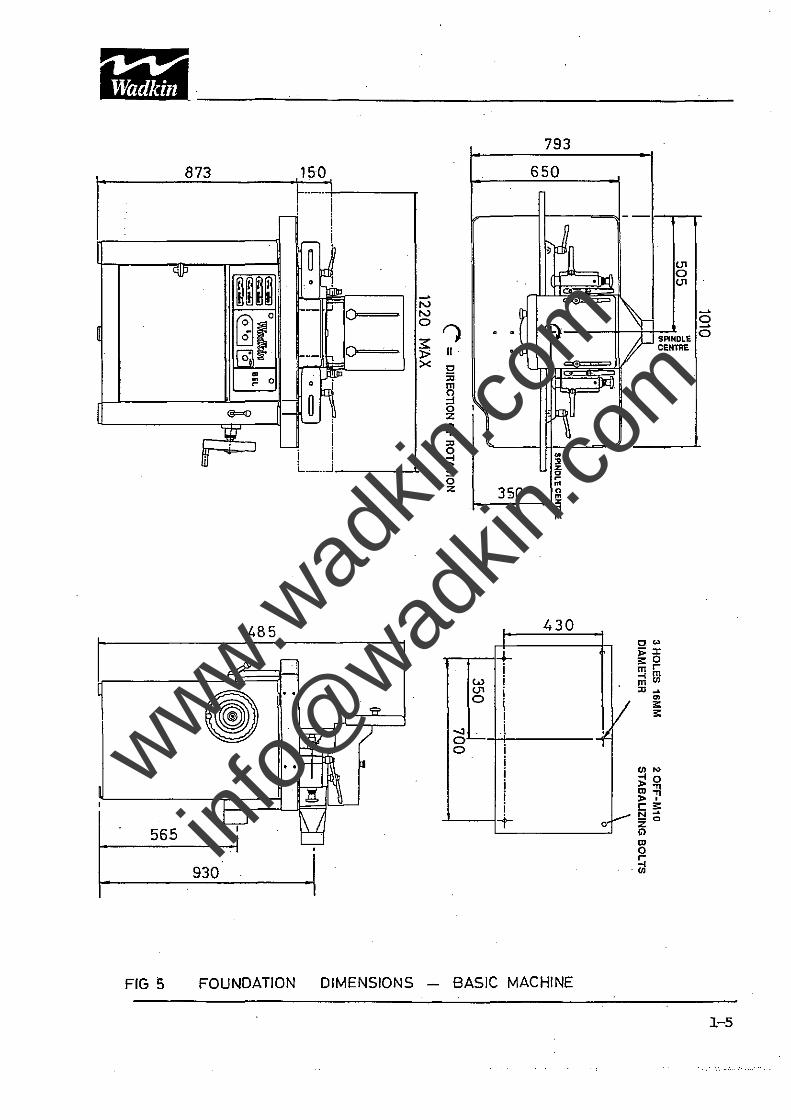
FIG 5 FOUNDATION DIMENSIONS - BASIC MACHINE
1-5
www.wad
kin.co
m
info@
wadkin
.com
873
~
'Uf'
~il~~ Hb
I~t. 0
m
" 0
@=()
1:;'
m-J ;
r
1485
565
930
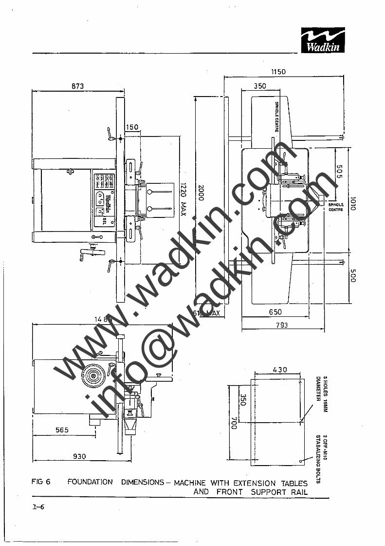
FIG 6 FOUNDATION
1--6
-'
"
-+ ~ 1-.. _-- _ , i i
.-!
~~ 1-.. - P'o
~o
iM -! i ! + I-"-"~
'-
N N o
l:5 o o
-'--- -610 MA)( I
.., 0 0
350
1150
o II %
~ o m % ;; m
., I U1 o U1
') "-r---n---r-~,.-- --+
650
793
, 430
, ~
i w U1 0
i i i i ..... ,
V
oV
"''' ;!~ ID." >. Cl!:: N-;;:0
" '" o
U1 o o
DIMENSIONS - MACHINE WITH EXTENSION TABLES ~ AND FRONT SUPPORT RAIL
www.wad
kin.co
m
info@
wadkin
.com
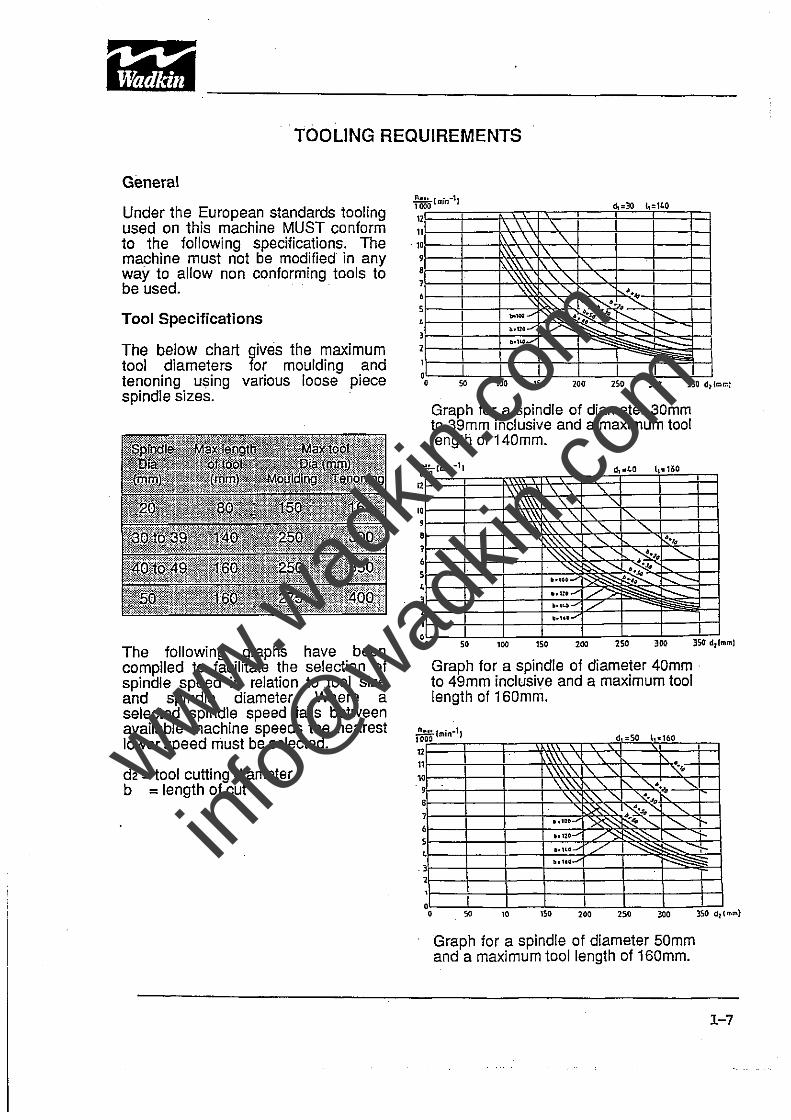
TOOLING REQUIREMENTS
General
Under the European standards tooling used on this machine MUST conform to the following specifications. The machine must not be modified in any way to allow non conforming tools to be used.
Tool Specifications
The below chart gives the maximum tool diameters for moulding and tenoning using various loose piece spindle sizes.
The following graphs have been compiled to facilitate the selection of spindle speed in relation to .tool size and spindle diameter. Where a selected spindle speed falls between available machine speeds the nearest lower speed must be selected.
d2 = tool cutting diameter b = length of cut
1 ., 1 1 0
9
• , • 5 , l 1
1
0 o
~30t140 . "
\ \ \ .\ \ '\
\\\ \ \ ,\\\ \ ,
" \\\\ ," " ,~ .",,-1'- ....
~." 1 ..... / ~ .~>t-1 hUO"'"
O.I~-
I 1 1
so 100 150
Graph for a spindle of diameter 30mm to 39mm inclusive and a maximum tool length of 140mm.
n-::~lmin-l1 .LO ,'" 1
1
\ \ \ 1\ \
\ " , 1"-\\ ~, , 1'\'- " 1:\.'\"-"- " ~.,.
""~ "- ~., "-"0
~~ , t---:---.. ",/ ./ I---"'~ I-..... / 1
so lOO 150 100 lSO 300 350 d,l
Graph for a spindle of diameter 40mm . to 49mm inclusive and a maximum tool length of 160mm.
mml
r.~ .. so 1 .. 160
,\\\ , \'\ " , "- "- ". . '\ ~\ " " "'-
" ," " ~ .. ~,l~" "-...... ~ ~" "-... i-... ,,/ ~ ",,,,-,,- i"'--- ~
•• M· /' -....::
~ ..... ---
so 10 lSO 100 15 0 300
Graph for a spindle of diameter 50mm and a maximum tool length of 160mm.
350 0 I
1-7
www.wad
kin.co
m
info@
wadkin
.com
1"":1# ~ 1h -----------------------------------------------
1-8
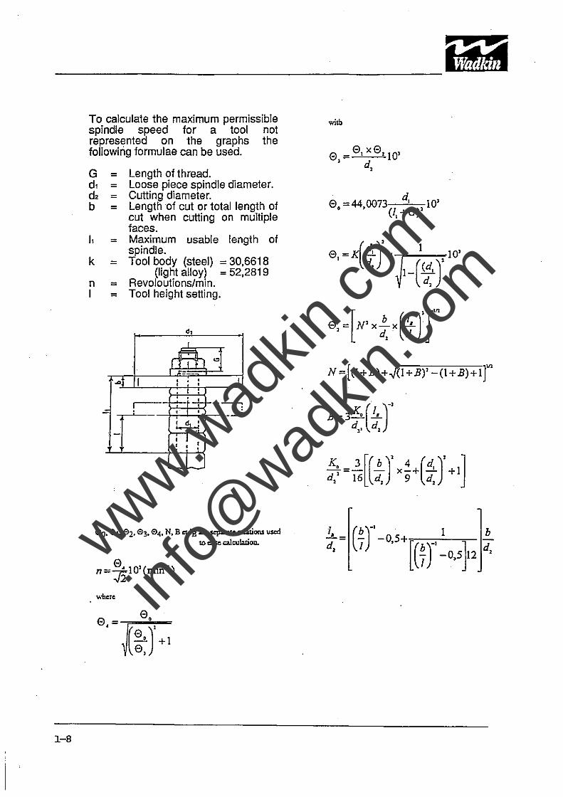
To calculate the maximum permissible spindle speed for a tool not represented on the graphs the following formulae can be used.
G = Length of thread. d, = Loose piece spindle diameter. d2 = Cutting diameter. b = Length of cut or total length of
cut when cutting on multiple faces.
), = Maximum usable length of spindle.
k = Tool body (steel) = 30.6618 (light alloy) = 52.2819
n = Revoloutions/min. I = Tool height setting.
d 1
I
r=r= I "'1 J I
---~l I • • I , • · , .-- ~
.: , • ----'
l.4-:! . -
• I , , • • ·
L "1
00.°1.°2. 0l. 04. N. B et IB:uesepame relations US<d to case c:alculatioD..
where
witb
° =0,x0'10' , d ,
° =44 0073 d, 10' • , (I,+G)'
N =[(l+B)+.J(1+B)' -(I+B)+l r B = 3 K, (iL)-'
d,. d,
:~ =]..[(.!!..)' x~+(!i)' +1] , 16 d, 9 d,
1 -!-= d, www.w
adkin
.com
info@
wadkin
.com
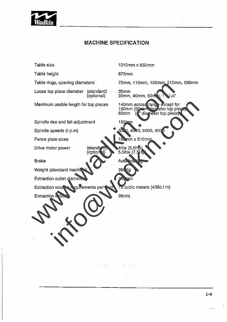
MACHINE SPECIFICATION
Table size
Table height
Table rings, opening diameters
Loose top piece diameter (standard) (optional)
Maximum usable length fortop pieces
Spindle rise and fall adjustment
Spindle speeds (r.p.m)
Fence plate sizes
Drive motor power (standard) (optional)
1010mm x 650mm
873mm
75mm, 11 Omm, 150mm, 210mm, 280mm
30mm 35mm, 40mm, 50mm, 1", 1,12"
140mm across range except for 160mm (50mm diameter top piece) 80mm (1" diameter top piece)
150mm
3000,4000,6000,8000
150mm x 510mm
4Kw (5.5Hp) 5.5Kw (7.5Hp)
Brake Auto braking
Weight (standard machine) 390Kg
Extraction outlet diameters 100mm
Extraction volume requirements per duct 13 cubic meters (436c.f.m)
Extraction velocity 26m/s
1-9
www.wad
kin.co
m
info@
wadkin
.com
.,
, , .U ,
" 12 L3
<.. < eZ ~ ","
~ ~ -<fl
~ <DZ
" "''' 0 "" El c> "'-I "':2: 0",·
~ ~
n Q
In ~ o.
'" '" '" c -. -. i<c: :0
'" '" '" '" 0 < ~-
~~ §~
< ~
> ~
;l~ ~
~ . - " ~
~ 0 m
•
~ ! ) ) ) '" ~ ,-0
~ 8Q)' §
s ~!
~ K i ;; ~~ C N
!i N " " ~
~ . N
C-__ 'b ~ '-~
l- ~ ~
v~~ , I"
~-_'\>~ ~
-...
:~ ..<Q =~ ~~ = 'i1 ~ .%
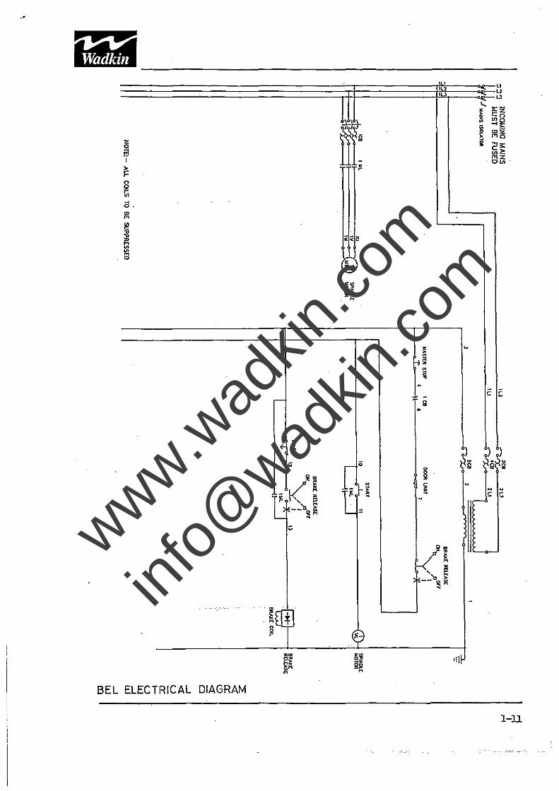
BEL ELECTRICAL DIAGRAM
l-U
www.wad
kin.co
m
info@
wadkin
.com
SECTION2 INSTALLATION
Unloading
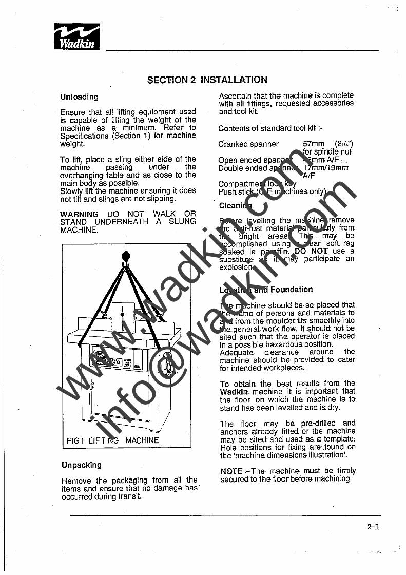
Ensure that all lifting equipment used is capable of lifting the weight of the machine as a minimum. Refer to Specifications (Section 1) for machine weight.
To lift, place a sling either sideo.f the machine passing under the overhanging table and as close to the main body as possible. . Slowly lift the machine ensuring it does not tilt and slings are not slipping.
WARNING DO NOT WALK OR STAND UNDERNEATH A SLUNG MACHINE.
1(1
I 11/
=01
FIG 1 LIFTING MACHINE
Unpacking
Remove the packaging from all the items and ensure that no damage has . occurred during transit.
Ascertain that the machine is complete with all fittings, requested accessories arid tool kit.
Contentsof.standard,tool kit;-
Cranked spanner
Open ended spanner Double ended spanner
57mm (2,14') for spindle nut 46mmNF,. 17mm/19mm A/F
Compartment lock key Push. stick (C.E machines. only)
Cleaning
Before levelling the machine remove. the anti-rust material particularly from the bright areas. This· may be accomplished using a clean soft. rag soaked in paraffin .. DO NOT use a substitute. as it may participate an explosion.
Location and Foundation
The machine should be so. placed that the traffic of persons and materials to and from the moulder fits smoothly into the.generai work flow. It should not be sited such that the operator is placed in a possible hazardous position. Adequate clearance around the machine should be provided. to cater for intended workpieces.
To obtain the best results. from the Wadkin; machine it is important that the floor on which the machine is to stand has been levelled and is. dry.
The floor may be pre-drilled and anchors already fitted. or the machine may be sited and used as a template. Hole positions for fixing,are.found on the 'machine dimensions illustration'.
NOTE:-The.· machine. must be firmly securedto the' floor before machining.
2-1
www.wad
kin.co
m
info@
wadkin
.com
"'1·#3. lh ------------------------------------------------~-----
2-2
Open the iront access :door to obtain access 10 'anchor bolts and the two l'earstabllizing bolts. The stabilizing
. bolts should be adjusted until they touch the iloorand then iastenedin position by tightening the locknuts. Fully lighten the anchor bolts.and close access door.
Supplies and Services
Electrical Supply The customer is responsible for an adequate electrical supply. Details of lhepower requirements are provided with the machine.
The machine is delivered with its complete electrical equipment ready for·connection.
The· electrical connection is at the rear . ofihe machine and an electrical schematic diagram can be found in the electrical cabinet as well as within this manual.
POINTS TO NOTE WHEN CONNECTING THEPOWER SUPPLY
A) Check 1he voltage, phase and frequency correspond to those on the motor plate.
B) Check the main fuses are of the correct capaCity in accordance with the machine nameplate.
C) Connect the incoming supply leads 10 the appropriate terminals.
D) Check all connectors are sound and that equipment is earthed.
E) Check the spindle rotation:When viewed iromthe ·front of the machine the rotational direction should be anticlockwise.lf this is incorrect reverse any two of the incoming mains leads after having first isolated the power.
Exhaust Connections The exhaust connections are located at the rear of the machine. The lower extraction being for the machine base and the upper extraction for the cutter.
Each outlet ·is 100mm in diameter and should be connected to the main extraction duct by a length of flexible hose.
The volume of air to be extracted at each outlet is 436 c.f.m at a rate of 26 meters per second.
www.wad
kin.co
m
info@
wadkin
.com
SECTION 3 OPERATING INSTRUCTIONS
Safety and Safety Devices
The safe operation of woodworking machinery requires constant alertness and close attention to the
. work in hand.
Before operating this machinery carefully read and understand the operational and safety aspects to be observed.
Blunt cutters often contribute to accidents. An efficient machinist knows when sharpening is necessary, but if there is a reluctance to spend time on grinding and resetting, the cutters may run beyond their efficient limits.
Cutters that have 'lost' their edge not only cut inefficiently, they tend to chop and snatch at the workpiece. This lowers the guality of finished work, but more seriously increases the risk of accidents.
A safety device prevents the machine from operating if the front access door is open and at the same time the door cannot be closed if the spindle lock is left engaged. .
Note:- The speed stamped on the cutters is their maximum operating speed NOT their normal operating speed at which they should be run.
Bi:!fore Operating the Machine
Ensure that all guards and fences are securely fitted and 'correctly adjusted. Guards and other safety devices are NOT' to be removed/opened while the machine is in operation.' They are there for YOUR SAFETY.
Ensure cutters/blades are the correct type and size for the prevailing machine conditions and workpiece.
Check cutters rotate in the correct direction of cut, are sharp and secu rely fastened.
Remove or securely fasten loose clothing; confine long hair and remove jewellery, etc.
Ensure adequate working space and lighting is provided~
Switch on all dust extraction equipment, ensure it is working correctly.
Check machine is in a safe and secure manner to operate.
It is bad practice to use cutters at the top of the spindle, always fit as low down as possible.
Check that any jigs to be used are robustly made, safe and appropriate for the workpiece and machine.
Check main is 'ON' and isolator at the rear of the machine is 'ON'.
During Machining
Wear suitable protective equipment, e.g. goggles, ear defenders, dust mask.
Stop the machine using the master stop before making adjustments or cleaning wood chips from' the work area.
Keep the floor area around the machine clean and free from wood refuse.
3-1
www.wad
kin.co
m
info@
wadkin
.com
'-1# s~ ~IA;,. ---------------------------------------------------------
Do not allow the floor to become slippery with oil or grease.
Report any machine malfunction or operator hazard to a person in authority immediately. Do not attempt to start or repair the machine unless qualified to do so. The machine must be immediately stopped using the master stop if running.
Ensure all power sources are isolated before commencing any maintenance work.
Comply with the Woodworking Machines Regulations. Failure to do so could result in legal proceedings.
Never leave the machine running whilst unattended.
Do not attempt to operate 1he machine while under the influence of anything that reduces your alertness.
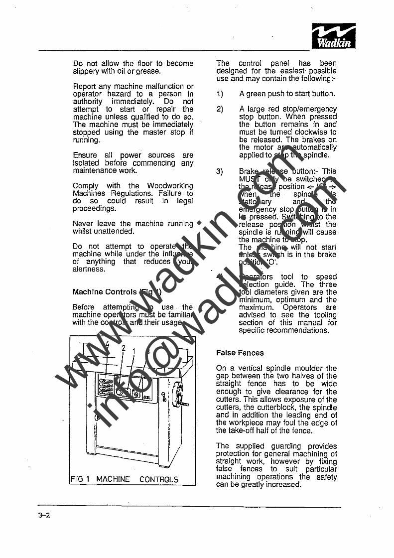
Machine Controls (Fig 1)
Before attempting to use· the machine operators must be familiar with the controls end their usage.
[ 4 2 1 3
~ L J- i , , 1
~ ~
'. ,.{
~ ~ \i(l .... ;
~ I: ; :l :! H
J. -lY FIG 1 MACHINE CONTROLS
The control panel has been designed for the easiest possible use and may contain the following:-
1)
2)
3)
4)
A green push to start button.
A large red stop/emergency stop button. When pressed the button remains in and must be turned clockwise to be released. The brakes on the motor are automatically applied to stop the spindle.
Brake release button:- This MUST only be switched to the release position..,.. (0) ~ when the spindle is stationary and the emergency stop button is in Le pressed. Switching to the release position whilst the spindle is running will cause the machine to stop. The machine will not start unless switch is in the brake position '0'.
Operators tool to speed selection guide. The three tool diameters given are the minimum, optimum and the maximum. Operators are advised to see the tooling section of this manual for specific recommendations.
False Fences
On a vertical spindle moulder the gap between the two halves of the straight fence has to be wide enough to give clearance for the cutte rs. This allows exposu re of the cutters, the cutterblock, the spindle and in addition the leading end of the workpiece may foul the edge of the take-off half of the fence.
The supplied guarding provides protection for general machining of straight work, however by fixing false fences to suit particular machining operations the safety can be greatly increased.
www.wad
kin.co
m
info@
wadkin
.com

A false fence replacing the supplied permali fence can substantially reduce or even close the fence gap leaving only the cutters exposed.
3-3
www.wad
kin.co
m
info@
wadkin
.com
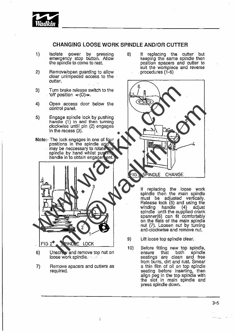
CHANGING LOOSE WORK SPINDLE AND/OR CUnER
1)
2)
3)
4)
5)
Isolate power by pressing emergency stop button. Allow the spindle to come to rest.
Remove/open guarding to allow clear unimpeded access to the cutter.
Turn brake release switch to the 'off' position +(O)~.
Open access door below the control panel.
Engage spindle lock by pushing handle (1) in and then turning clockwise untill pin (2) engages in the recess (3).
Note:- The lock engages in one of four positions in the spindle and it may be neccessary to rotate the spindle by hand whilst pushing handle in to obtain engagement.
. FIG 2 SPINDLE LOCK
6)
7)
Unscrew and remove top nut on loose work spindle.·· ... .
Remove spacers and cutters as required.
8) If replacing the cutter but keeping the same spindle then position spacers and cutter to suit the workpiece and reverse procedures (1-6) .
FIG3 SPI
If replacing the loose work spindle then the main spindle must be adjusted vertically. Release lock (5) and using the winding handle (4) adjust spindle until the supplied crank spanner(6) can fit comfortably on the flats of the main spindle
. nut (7). Loosen nut by turning anti-clockwise and remove nut.
9) Lift loose top spindle clear.
10) Before fitting new top spindle, ensure that both spindle seatings are clean and free from burrs, dirt and rust. Smear a thin film of oil on top spindle seating before inserting, then align peg in the top spindle with the slot in main spindle and press spindle down.
3-5
www.wad
kin.co
m
info@
wadkin
.com
------------------------------------------------11)
12)
13)
14)
15)
16)
17)
18)
Replace and tighten the main spindle nut. .
Select ring to suit cutter.
Fit new cutter and spacers to suit. Secure with loose spindle nut.
Disengage spindle . lock and close access door.
Check and if necessary alter spindle speed.
Engage brake motor.
Replace/close all guarding.
Release button.
emergency stop
Jii!IP .~ ~I§'"
www.wad
kin.co
m
info@
wadkin
.com
MACHINE ADJUSTMENTS
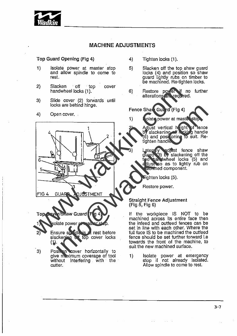
Top Guard Opening (Fig 4)
1)
2)
3)
4)
6
5
Isolate power at master stop and allow spindle to come to rest.
Slacken . off top cover handwheellocks (1).
Slide cover (2) forwards until locks are behind hinge.
Open cover.
FIG 4 GUARD ADJUSTMENT
Top CoverlShaw Guard (Fig 4)
1)
2)
3)
Isolate power at master stop.
Ensure spindle is at rest before slackening off top cover locks (1 ).
Position cover horizontally to give maximum coverage of tool without interfering. with· the cutter.
4)
5)
6)
Tighten locks (1).
Slacken off the top shaw guard locks (4) and position so shaw guard lightly rubs on timber to be machined. Re-tighten locks.
Restore power if no further alterations are required.
Fence Shaw Guard (Fig 4)
1)
2)
3)
Isolate power at master stop.
Adjust vertical height of fence by slackening off locking handle (6) and positioning to suit. Retighten handle.
Laterally adjust fence shaw guard (3) by slackening off the two handwheel locks (5) and adjust so as to lightly rub on machined component.
4) Tighten locks (5).
5) Restore power.
Straight Fence Adjustment (Fig 5, Fig 6)
If the workpiece IS NOT to be machined across its entire face then the infeed and outfeed fences can be set in line with each other. Where the full face IS to be machined the outfeed fence should be set further forward Le towards the front of the machine, to suit the new machined surface.
1) Isolate power at emergency stop if not already isolated. Allow spindle to come to rest.
3-7
www.wad
kin.co
m
info@
wadkin
.com
PeP ~ IdflAl1I
--------------------------------------------~-
3-8
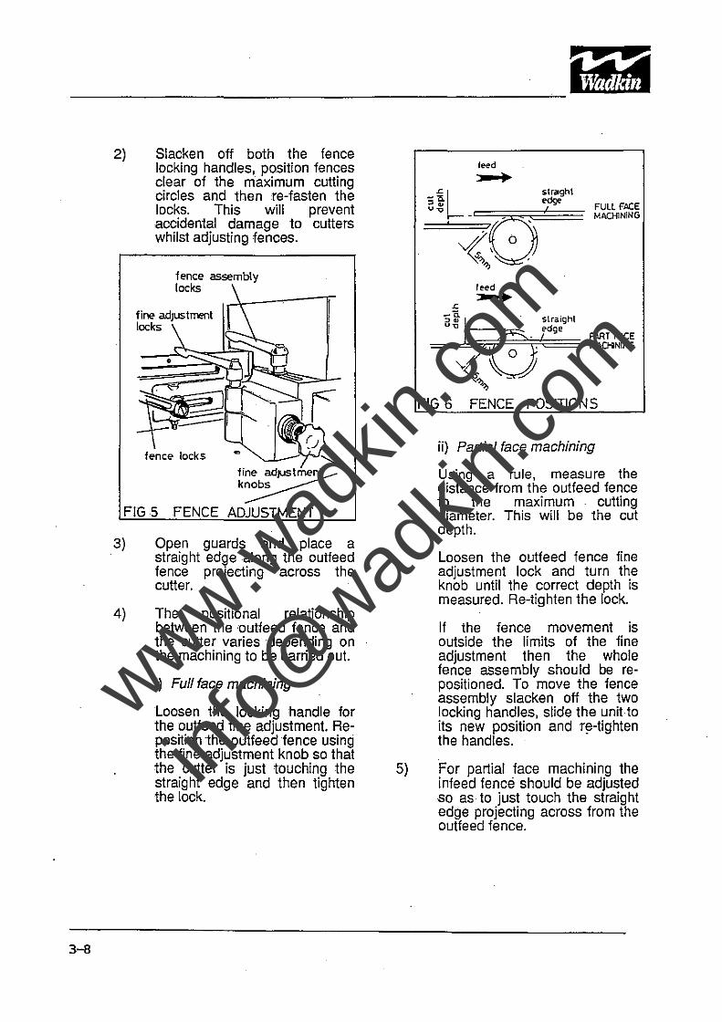
2) Slacken off both the fence locking handles, position fences clear of the maximum cutting circles and then re-fasten the locks. This will prevent accidental damage to cutters whilst adjusting fences.
fence assembly locks
•
fence locks
r ~" fi~~b~JUs~
k~ FIG 5 FENCE ADJUSTMENT
3)
4)
Open guards and place a straight edge along the oulfeed fence projecting across the cutter.
The positional relationship between 1heoutfeed fence and the cutter varies depending on the machining to be carried out.
i) Full face machining
Loosen the locking handle for the outfeed fine adjustment. Reposition the oulfeedfence using the iine adjustment knob so that the cutter is just touching the straight edge and then tighten the lock.
5)
straght
~~~,~dge== FULL FACE -:: MACHINING
reed ~
straight ~dge
==:b~p~~~== PART FACE MACHINING
FIG 6 FENCE POSITIONS
ii) Partial face machining
Using a rule, measure the distance from the outfeed fence to the maximum cutting diameter. This will be the cut depth.
Loosen the outfeed fence fine adjustment lock and turn the knob until the correct depth is measured. Re-tighten the lock.
If the fence movement is outside the limits of the fine adjustment then the whole fence assembly should be repositioned. To move the fence assembly slacken off the two locking handles, slide the unit to its new position and rl'-tighten the handles.
For partial face machining the infeed fence should be adjusted so as to just touch the straight edge projecting across from the outfeed fence.
www.wad
kin.co
m
info@
wadkin
.com
6)
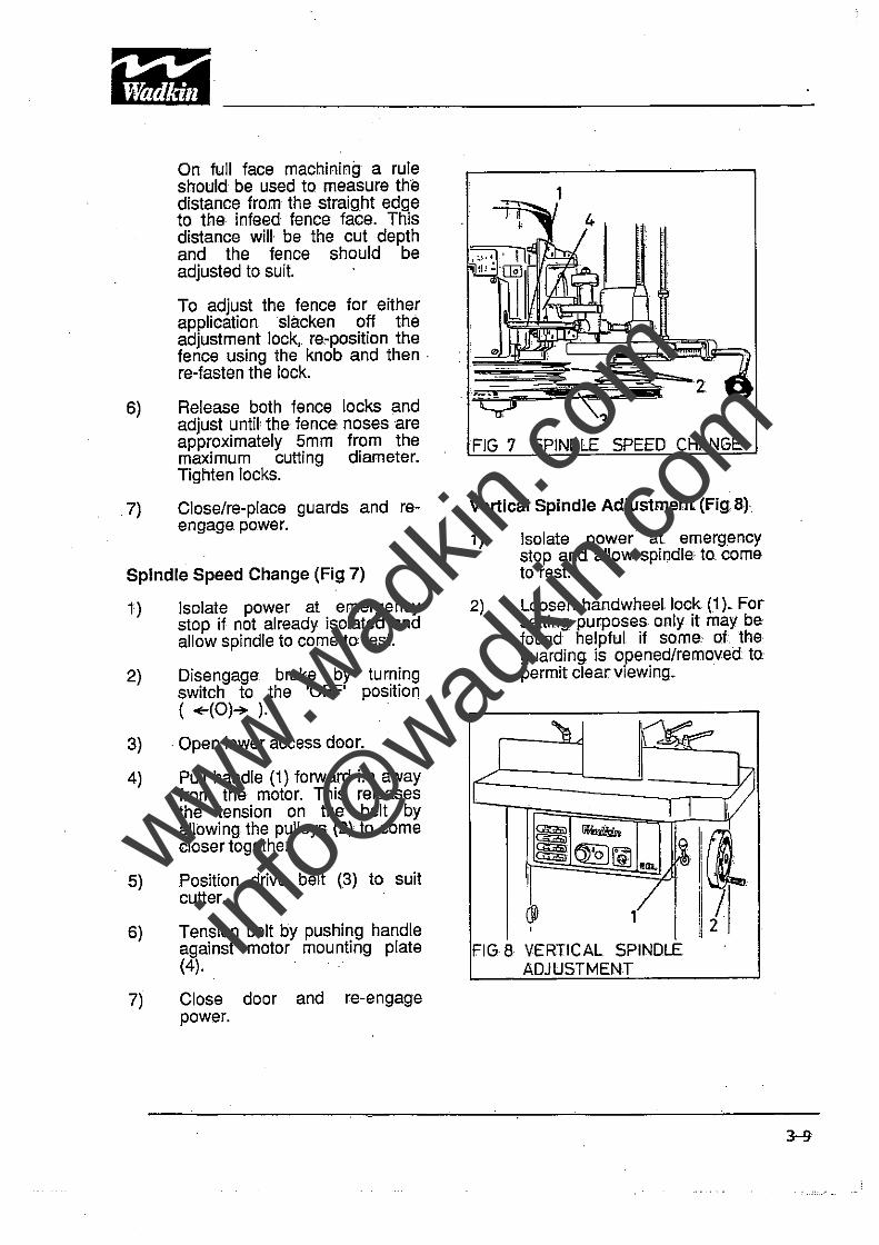
On full face machining a rule should be used to measure the distance from the straight edge to the infeed fence face. This distance will be the cut depth and the fence should be adjusted to suit.
To adjust the fence for either application slacken off the adjustment lock,. re.-position the fence using the knob and then· re-fasten the lock.
Release both fence locks and adjust until the fence noses are approximately 5mm from the maximum cutting diameter. Tighten locks.
.7) Close/re-place guards and reengage. power.
Spindle Speed Change (Fig 7)
1)
2)
3)
4)
5)
6)
7)
Isolate power at emergency stop if not already isolated and allow spindle to come to rest.
Disengage brake by turning switch to the 'OFF' position ( +-(O)~ ).
. Open lower access door.
Pull handle (1) forward i.e away from the motor. This releases the tension on the belt by allowing the pulleys (2) to come closer together.
Position drive belt (3) to suit cutter.
Tension belt by pushing handle against motor mounting plate (4).
Close door and re-engage power.
FIG 7
Vertical Spindle Adjustment (Fig. 8)
1)
2)
[ /'
Isolate power at emergency stop and allow spindle to. come to rest.
Loosen handwheellock(1 ) .. For setting purposes only it may be found helpful if some of the guarding is opened/removed to permit clear viewing.
."\l ~~----='
~
1 l V ~~ '(1 ~:~ ~19J ~ ,I o. . G 'Ia
I
@ ,7 I, I , P
FIG 8 VERTICAL SPINDLE ADJUSTMENT
www.wad
kin.co
m
info@
wadkin
.com
Jii£' •• ~
'~lttl11 ------------------------------~--------------
3-10
3) Raise or lower the spindle by' turning thehandwheel (2) to SUIt the workpiece or by reading off the digital readoutlocated behind the handwheel (2).
Note:-Whilst the rise and fall movement of the spindle provides Immediate adjustment of cutter height, further ,adjustment outside this range can lJeachieved by repositioning1he collars on the work spindle. Where avoidable, 'cutlers should not be positioned at the top of the work spindle.
4) Tighten 'handwheel lock (1) when set.
5) Re-engage power.
Table Bings Bemoval/Be-placement
The rings ,are machined toa fine tolerance to ensure a close fit between each other. To :prevent the rings rotating ':each ring has a pin which locates in 'the next ring or in the case of 1heouter ring, the main 'table. Because of the close tolerances rings must be removed or fitled squarely to the table.
The following sequence of operations must be performed with the power 'OFF'and isolated and with the cutler removed.
1) Position guards to allow unimpeded,access.
2) Release fence plate locks and position fences at their :extremities. In this position it is possible 10 remove or replace either or both of the two inner rings.
3)
4)
5)
6)
7)
To remove or replace the outer rings the fence locks have to be totally unscrewed and the fences removed (see Section 3-Straight fence adjustment Fig 5). .
Re-fit cutler.
Replace/re-position Re-position fences and tighten locks.
Replace guards and reset if necessary.
Restor:e power.
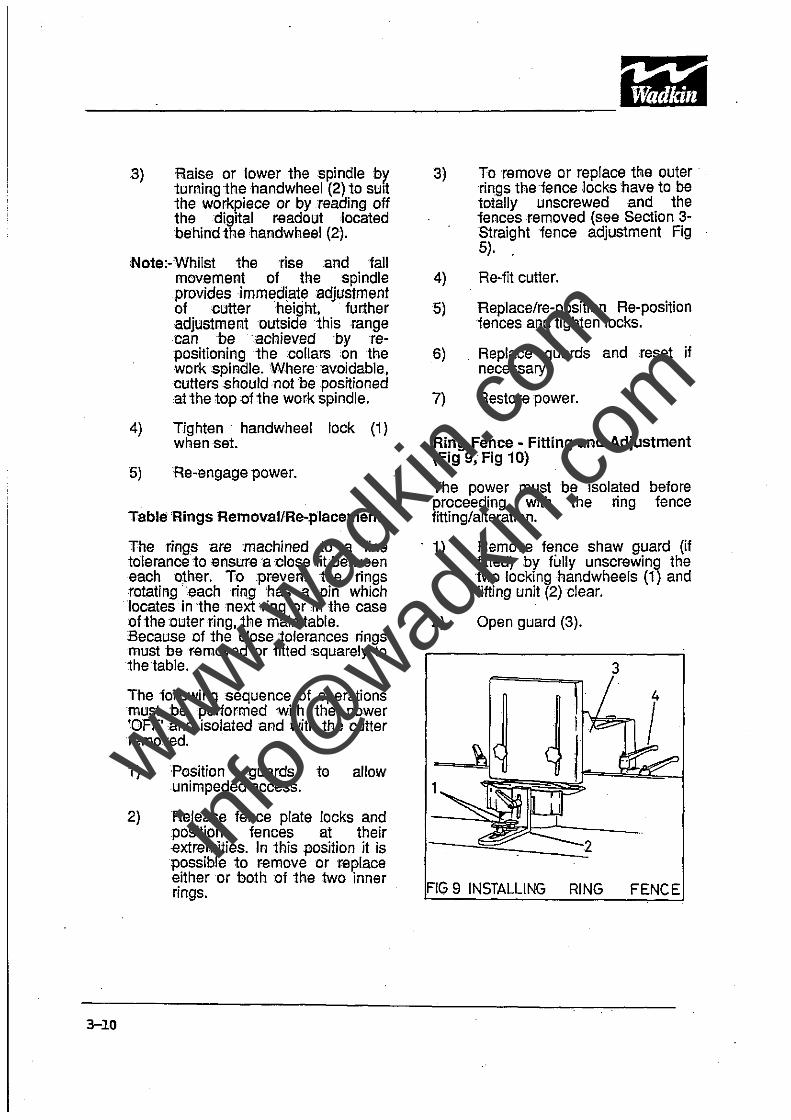
Ring Fence - Fitting and Adjustment (Fig 9, Fig 10)
The power must proceeding with fitting/alteration.
be isolated before the ring fence
. 1)
2)
Remove fence shaw guard (if fitted) by fully unscrewing the two lockinghandwheels (1) and lifting unit (2) clear.
Open guard (3).
9 INSTALLING RING FENCE
www.wad
kin.co
m
info@
wadkin
.com
PE1• _I11III !~A;"
--~----------~-----------------------
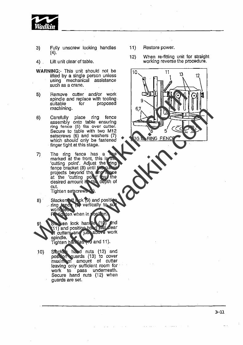
3)
4)
Fully unscrew locking handles (4).
Lift unit clear oftable.
WARNING;- This unit should not be lifted by a single person unless using mechanical assistance such as a crane.
5)
6)
7)
8)
9)
~O)
Remove cutter and/or work spindle and replace with tooling· suitable for proposed machining.
Carefully place ring fence assembly onto table ensuring ring fence (5) fits over cutter. Secure to table with two M12 setscrews (6) and washers (7) which should only be fastened finger tight at this stage.
The ring fence has a line marked at the front, this is the 'cutting point'. Adjust the ring fence bracket (8) until the cutter projects beyond the ring fence at the 'cutting point' by the desired amount Le the depth of cut. Tighten setscrews (6).
Slacken off lock (g) and position . ring fence (5) vertically to suit workpiece. Re-tighten when in position.
Slacken lock handle (10). and (11) and position hood just clear of cutters and just above work spindle. Tighten handles (10 and 11).
Slacken hand nuts (12) and position guards (13) to cover maximum amount of cutter leaving only sufficient room for . work to pass underneath. Secure hand nuts (12) when guards are set.
11)
12)
10"
Restore power.
When re-fitting unit for straight working reverse the procedure.
11 \
13
6,7
~
FIG 10 RING FENCE
3-D
www.wad
kin.co
m
info@
wadkin
.com
SECTION4 MAINTENANCE
Scheduled Maintenance
Scheduled maintenance consists of regularly maintaining the machine in a good operating condition, capable of safely producing good quality trouble free work, with the minimum of down time;
This inclUdes tasks such as regular cleaning and lubrication which can and should be performed by the operator.
Much attention has been given to keeping lubrication and maintenance down to a minimum. In consequence the cutterblock spindle has been fitted with permanently lubricated bearings.
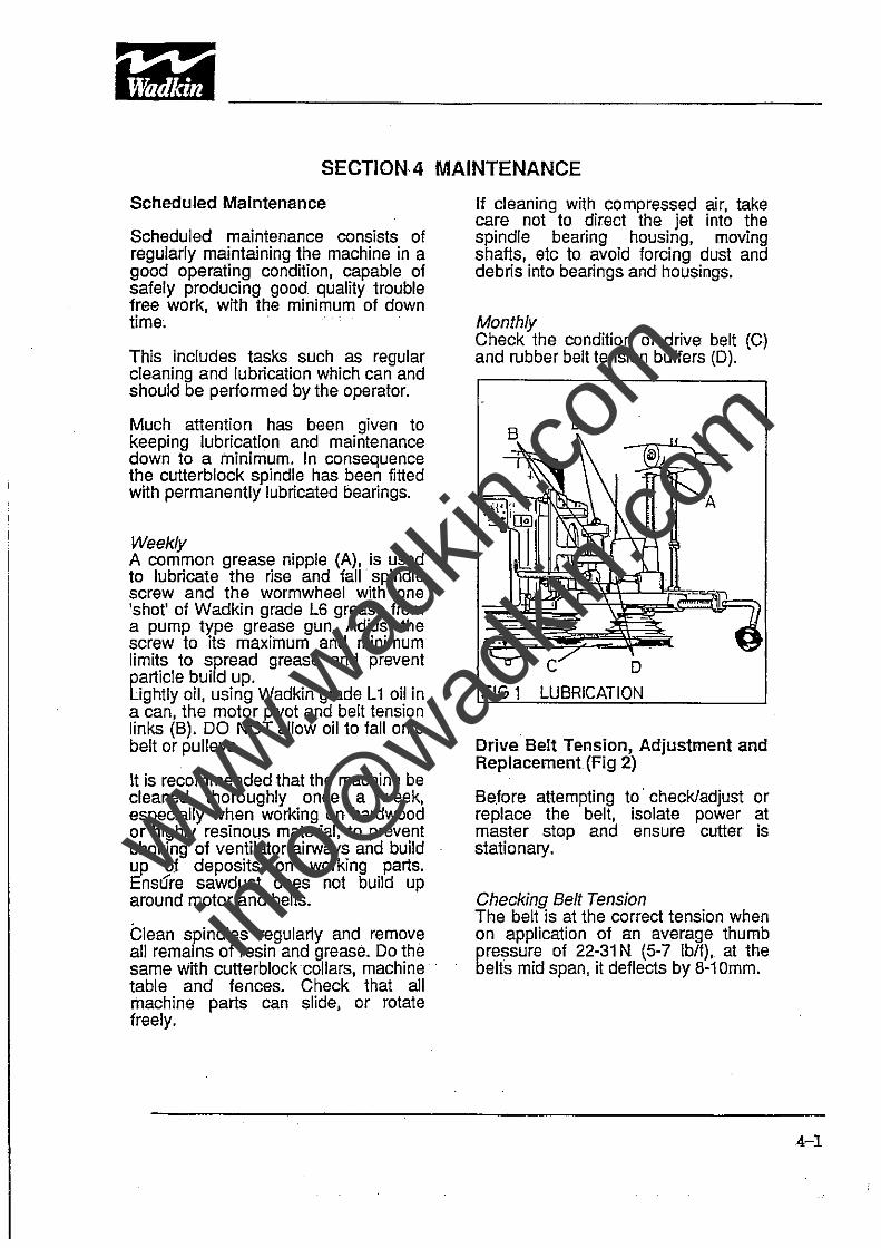
Weekly A common grease nipple (A), is used to lubricate the rise and fall· spindle screw and the wormwheel with one 'shot' of Wadkin grade L6 grease. from a pump type grease gun. Adjust the screw to its maximum and minimum limits to spread grease and prevent particle build up. Lightly oil, using Wadkin grade L 1 oil in a can, the motor pivot and belt tension links (B). DO NOT allow oil to fall onto belt or pulleys.
It is recommended that the machine be cleaned thoroughly once a week, especially when working on hardwood or highly resinous material, to prevent choking of ventilator airways and build up oj deposits on working parts. Ensure sawdust does not build up around motor and belts.
Clean spindles regularly and remove all remains of resin and grease. Do the same with cutterblockcoliars, machine table and fences. Check that all machine parts can slide, or rotate freely.
If cleaning with compressed air, take care not to direct the jet into the spindle bearing housing, moving shafts, etc to avoid forcing dust and debris into bearings and housings.
Monthly Check the condition of drive belt (Cl and rubber belt tension buffers (D).
Drive Belt Tension, Adjustment and Replacement (Fig 2)
Before attempting to· check/adjust or replace the belt, isolate power at master stop and ensure cutter is stationary.
Checking Belt Tension The belt is at the correct tension when on application of an average thumb pressure of 22-31 N (5-7 Ib/l), at the belts mid span, it deflects by 8-10mm.
4-1
www.wad
kin.co
m
info@
wadkin
.com
~I· ?. 11,W!i ------------------------~---------------------
4-2
Adjustment After a period of time the stiffness of the buffers (1) may reduce and this could cause the pulley centres to 'wave'. If this happens,slightly tighten the locknuts either side by an equal amount to compress the buffers.
2 DRIVE BELT
To adjust the belt tension the locknuts behind the buffers (1) should be loosened and the buffers re-positioned to suit the threaded handle (2).
Replacement To rep'lace a belt follow the procedure descnbed in 'Section 3- Spindle speed changing'except replace the belt instead of re-positioning.
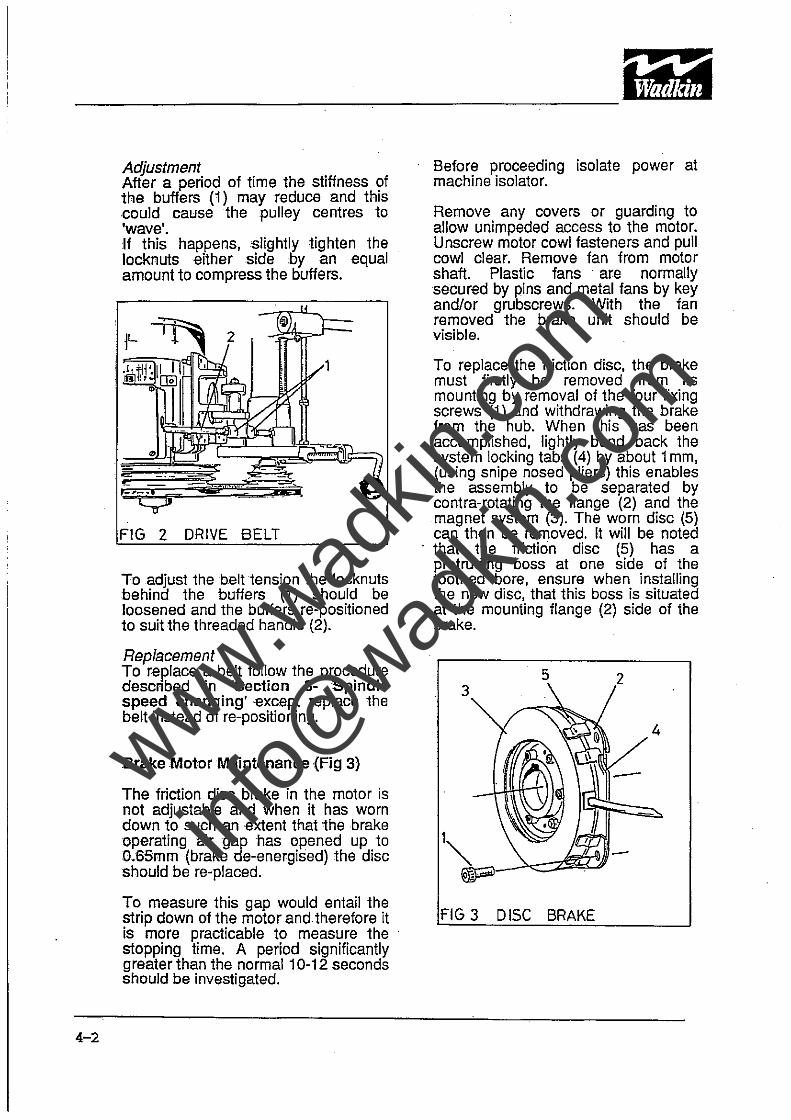
Brake Molor Maintenance (Fig 3)
The friction disc brake in the motor is not adjustable and when it has worn down to such an extent that the brake operating air gap has opened up to 0.65mm (brake de-energised) the disc should be re-placed.
To measure this gap would entail the strip down of the motor and therefore it is more practicable to measure the stopping time. A period significantly greater than the normal 10-12 seconds should be investigated.
Before proceeding isolate power at machine isolator.
Remove any covers or guarding to allow unimpeded access to the motor. Unscrew motor cowl fasteners and pull cowl clear. Remove fan from motor shaft. Plastic fans· are normally secured by pins and metal fans by key and/or grubscrews. With the fan removed the brake unit should be visible.
To replace the friction disc, the brake must firstly be removed from its mounting by removal of the four fixing screws (1) and withdrawing the brake from the hub. When this has been accomplished, lightly bend back the system locking tabs (4) by about 1 mm, (using snipe nosed pliers) this enables the assembly to be separated by contra-rotating the flange (2) and the magnet system (3). The worn disc (5) can then be removed. It will be noted
. that the friction disc (5) has a protruding boss at one side of the toothed bore, ensure when installing the new disc, that this boss is situated at the mounting flange (2) side of the brake.
4
fiG 3 DISC BRAKE
www.wad
kin.co
m
info@
wadkin
.com

To re-assemble, reverse the dismantling procedure then ensure the . locking tabs (4) .are fully re-clamped. Visually centralise the disced toothed bore by thumb pressure, then re-mesh onto the brake hub, re-fasten into position by fixing screws (1). Replace fan, cowl and any removed guards or covers, ensuring they are .securely fastened where necessary .
. ' /'
4-3
www.wad
kin.co
m
info@
wadkin
.com
WAD KIN CASTROl
l1
L2
L4
l6
L10il
L20il
L4 Oil
Hyspin AWS32
Alpha ZN 150
Magna 68
Spheerol AP3
L6 Grease
.' /
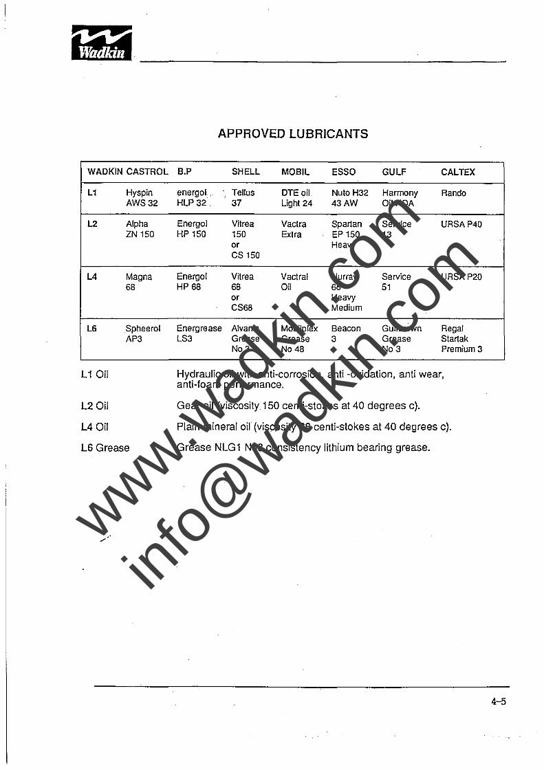
APPROVED LUBRICANTS
B.P SHEll MOBll ESSO GULF CAlTEX
energoi, Tellus DTEoil Nuto H32 Harmony Rando HLP32 37 Light 24 43AW OilHDA
Energol Vitrea Vactra Spartan Service URSA P40 HP 150 150 Extra EP 150 13
or Heavy CS 150
Energol Vitrea Vactral Nurray Service URSA P20 HP 68 68 Oil 68 51
or Heavy CS68 Medium
Energrease Alvania Mobilplex Beacon Gulfcrown Regal LS3 Grease Grease 3 Grease Startak
No3 No 48 No3 Premium 3
Hydraulic oil with anti-corrosion, anti -oxidation, anti wear, anti-foam performance.
Gear oil (viscosity 150 centi-stokes at 40 degrees c).
Plain mineral oil (viscosity 68 centi-stokes at 40 degrees c).
Grease NLG1 No3 consistency lithium bearing grease.
4-5
www.wad
kin.co
m
info@
wadkin
.com
SECTION 5 ILLUSTRATED PARTS LIST
CONTENTS
1. Fence Assembly
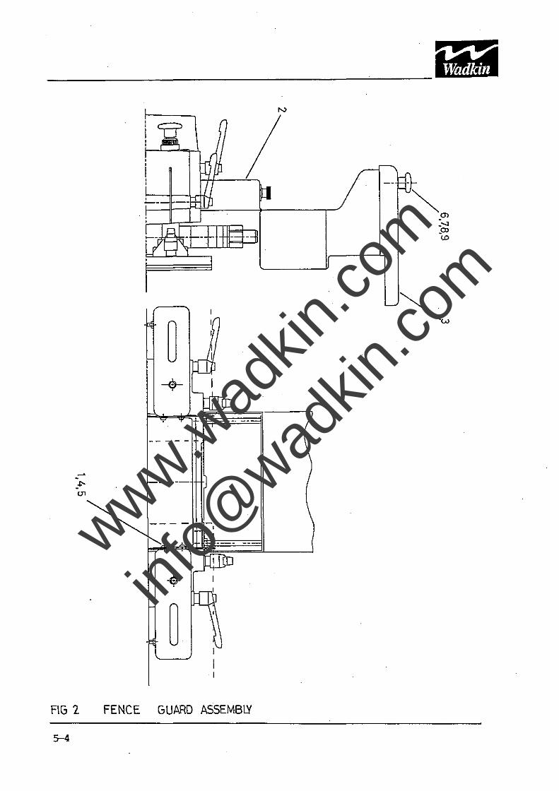
2. Fence Guard Assembly
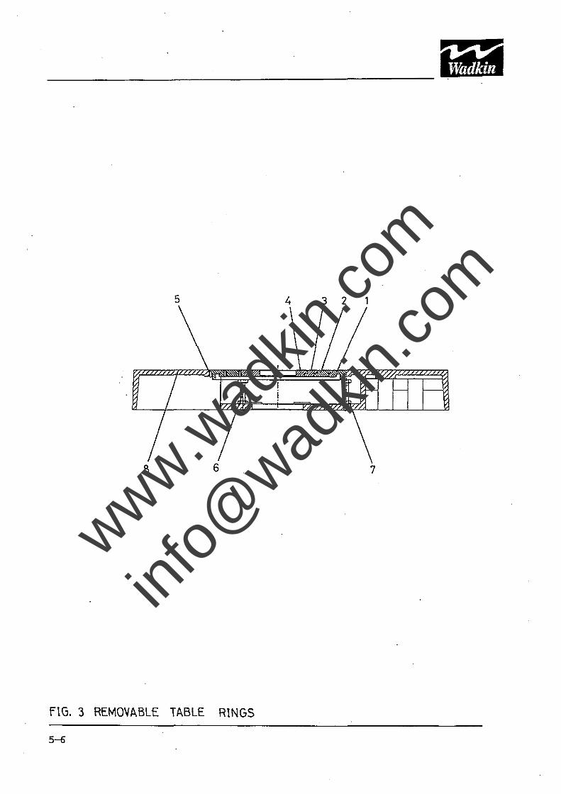
3. Removable Table Rings
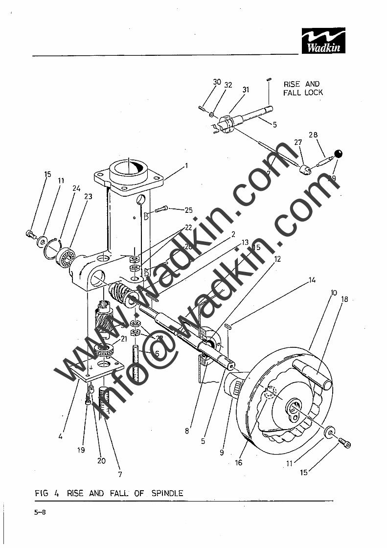
4. Spindle Rise and Fall
5. Spindle Assembly
6. Motor Mounting and Belt Tensioner
7. Loose Top Piece
8. Ring Fence
9. Optional Side Tables and Front Support Rail
5-1
www.wad
kin.co
m
info@
wadkin
.com
9, 22,23
3
2
1
o 0
20,21 o
6, 6,B,9 6,7
10.11
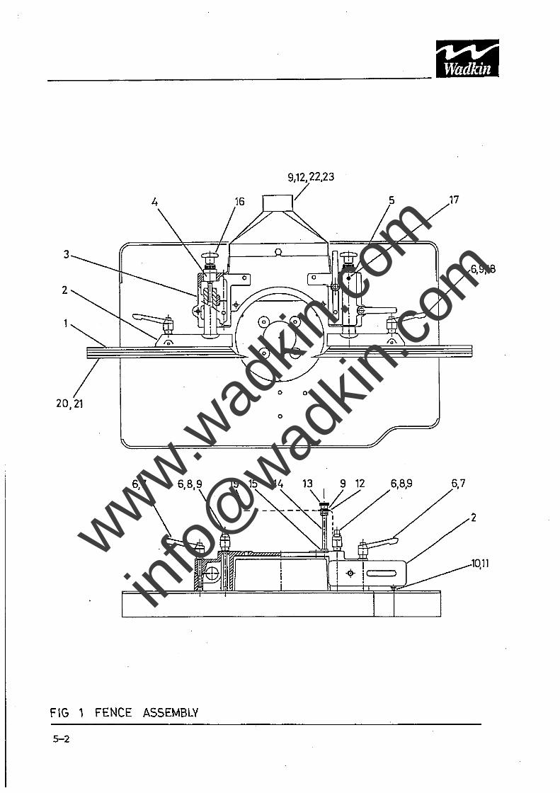
FIG 1 FENCE ASSEMBLY
5-2
www.wad
kin.co
m
info@
wadkin
.com
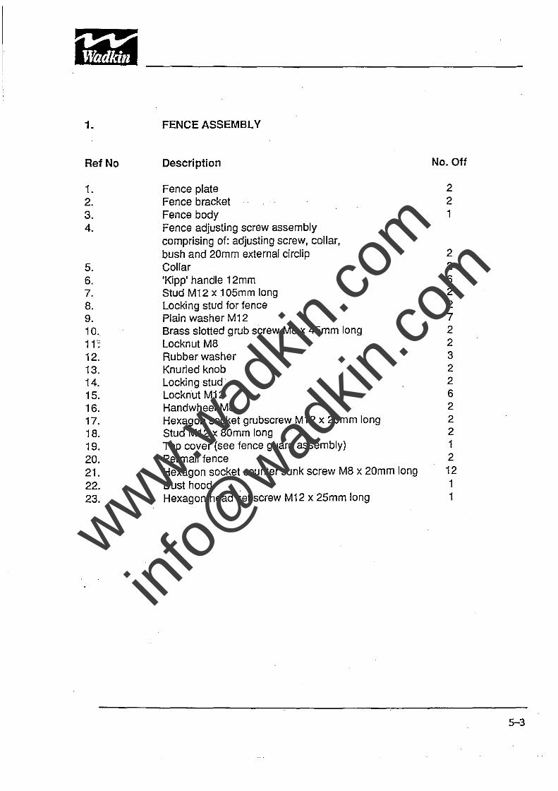
1. FENCE ASSEMBLY
Ref No Description No. Off
1. Fence plate 2 2. Fence bracket 2 3. Fence body 1 4. Fence adjusting screw assembly
comprising of: adjusting screw, collar, bush and 20mm external circlip 2
5. Collar 2 6. 'Kipp' handle 12mm 6 7. Stud M12 x 1 05mm long 2 B. Locking stud for fence 2 9. Plain washer M12 7 10. Brass slotted grub screw M8 x 45mm long 2 11: Locknut M8 2 12. Rubber washer 3 13. Knurled knob 2 14. Locking stud 2 15. Locknut M12 6 16. Handwheel M8 2 17. Hexagon socket grubscrew M12 x 20mm long 2 18. Stud M12 x 80mm long 2
19. Top cover (see fence guard assembly) 1
20. Permali fence 2
21. Hexagon socket counter sunk screw M8 x 20mm long 12
22. Dust hood 1
23. Hexagon head set screw M12 x 25mm long 1
5-3
www.wad
kin.co
m
info@
wadkin
.com
----------------------------------~-----
_.f;(J1
FIG 2 FENCE GUARD ASSEMBlY
N
Ilia I ,
www.wad
kin.co
m
info@
wadkin
.com

2. FENCE GUARD ASSEMBLY
Ref No . Description No. Off
1. Chip deflector 2 2. Top cover, 1 3. Front visor 1 4. Hexagon socket button head screw MS x 20mm long 4
5. Plain washer MS 4
6. Stud MS x 30mm long 2 7. Fibre washer 4
S. Plastic handwheel MS 2 9. Plain large diameter washer M8 2
5-5
www.wad
kin.co
m
info@
wadkin
.com
5 4 3 2 1
8 6 7
FIG. 3 REMOVABLE TABLE RINGS
5-6
www.wad
kin.co
m
info@
wadkin
.com
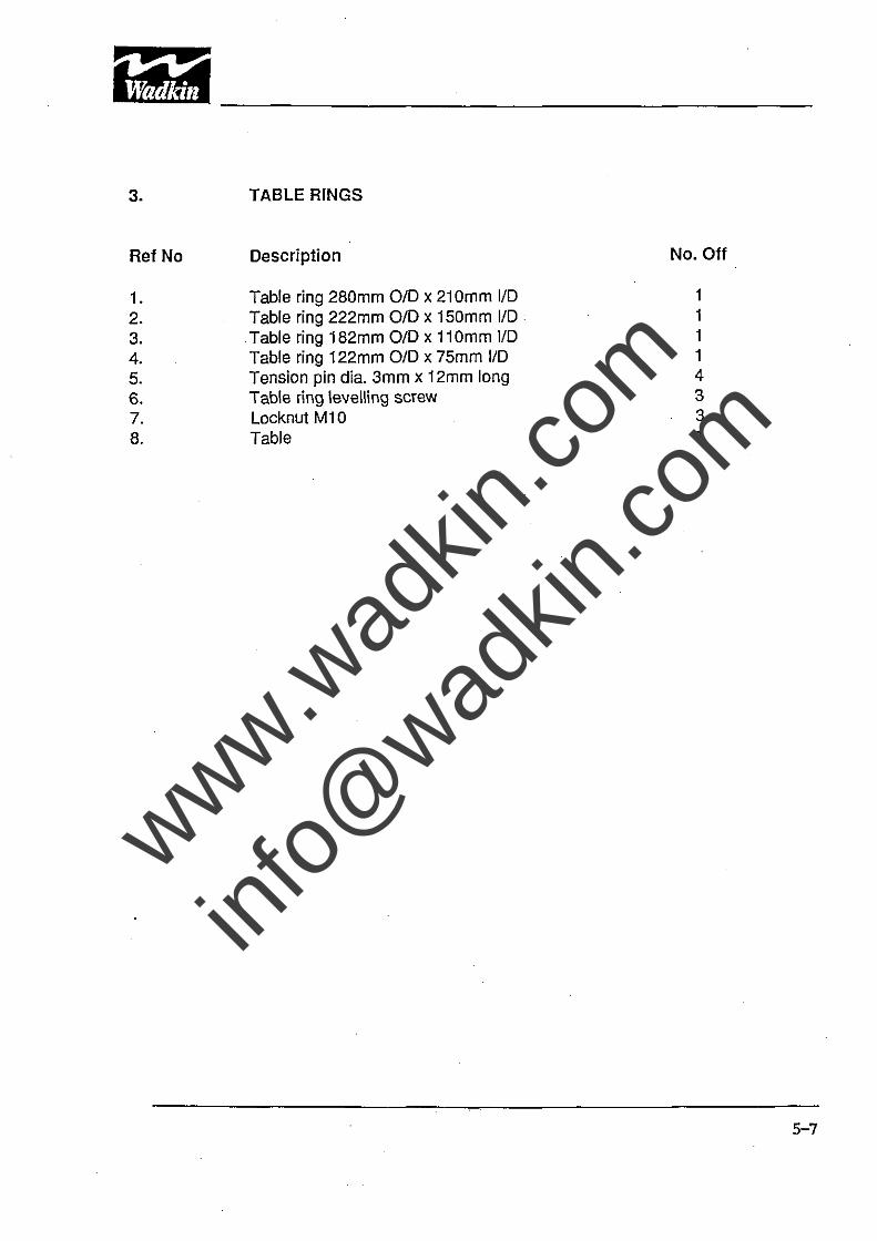
3.
Ref No
1. 2. 3. 4. 5. 6. 7. 8.
TABLE RINGS
Description
Table ring 280mm 010 x 210mm 110 Table ring 222mm 010 x 150mm 110
.Table ring 182mm 010 x 110mm 110 Table ring 122mm 010 x 75mm 110 Tension pin dia. 3mm x 12mm long Table ring levelling screw Locknut M10 Table
No. Off
1 1 1 1 4 3 3 1
5-7
www.wad
kin.co
m
info@
wadkin
.com
------------------------------------~---
I,i.a ' 11
30 <"
/
32 31 RISE AND
/
FALL LOCK
'"'~5 ~~ "- 28
~ 17 29
2 13 15
12
19
16 11 7 15
FIG 4 RISE AND FALL OF SPINDLE
5-8
www.wad
kin.co
m
info@
wadkin
.com
4.
Ref No
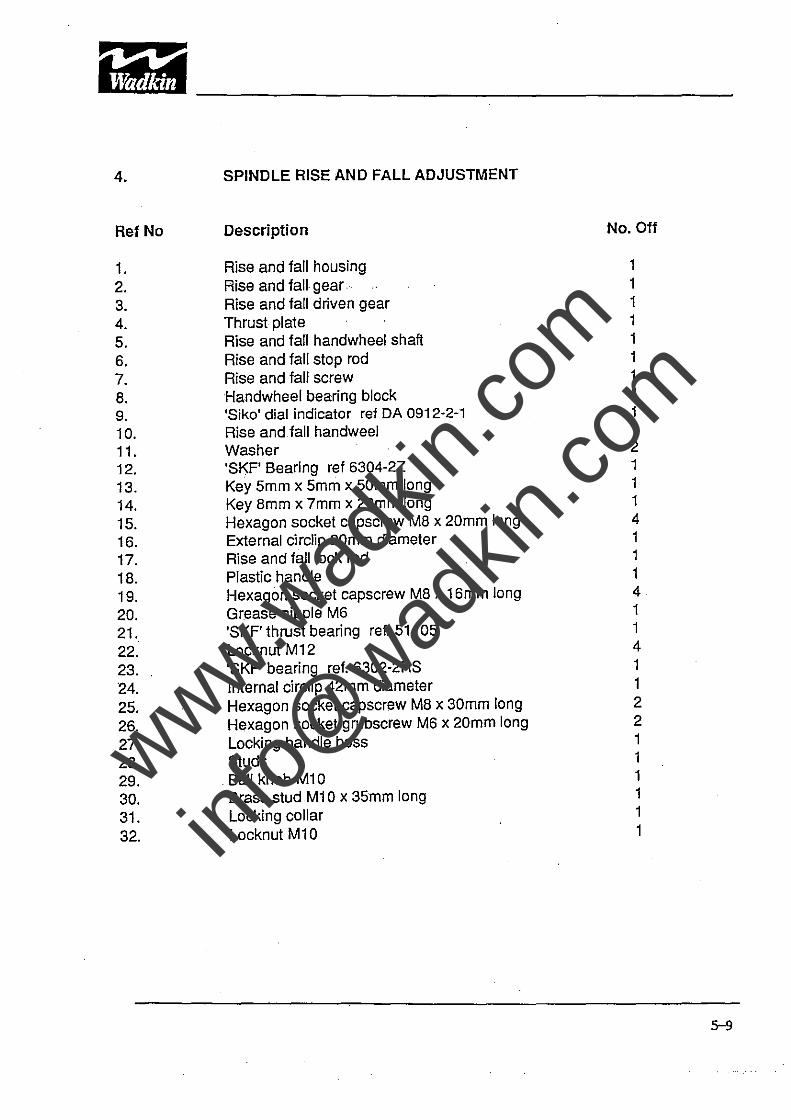
1. 2. 3. 4. S. 6. 7. S. 9. 10. 11. 12. 13. 14. 1S. 16. 17. 1S. 19. 20. 21. 22. 23. 24. 2S. 26. 27. 2S. 29. 30. 31. 32.
SPINDLE RISE AND FALL ADJUSTMENT
Description
Rise and fall housing Rise and fall· gear ... Rise and fall driven gear Thrust plate Rise and fall handwheel shaft Rise and fall stop rod Rise and fall screw Handwheel bearing block 'Siko' dial indicator ref DA 0912-2-1 Rise and fall handweel Washer 'SKF' Bearing ret 6304-2Z Key Smm x Smm x SOmm long Key Smm x 7mm x 20mm long Hexagon socket capscrew MS x 20mm long External circlip 20mm diameter Rise and fall lock rod Plastic handle Hexagon socket capscrew MS x 16mm long Grease nipple M6 'SKF' thrust bearing ret. S11 OS Locknut M12 'SKF' bearing reI. 6302-2RS Internal circlip 42mm diameter Hexagon socket capscrew MS x 30mm long Hexagon socket grubscrew M6 x 20mm long Locking handle boss Studs .
. Ball knob M10 Brass stud M10 x 35mm long Locking collar Locknut M10
No. Off
1 1 1 1 1 1 1 1 1 1 2 1 1 1 4 1 1 1 4 1 1 4 1 1 2 2 1 1 1 1 1 1
5-9
www.wad
kin.co
m
info@
wadkin
.com
B
l e-
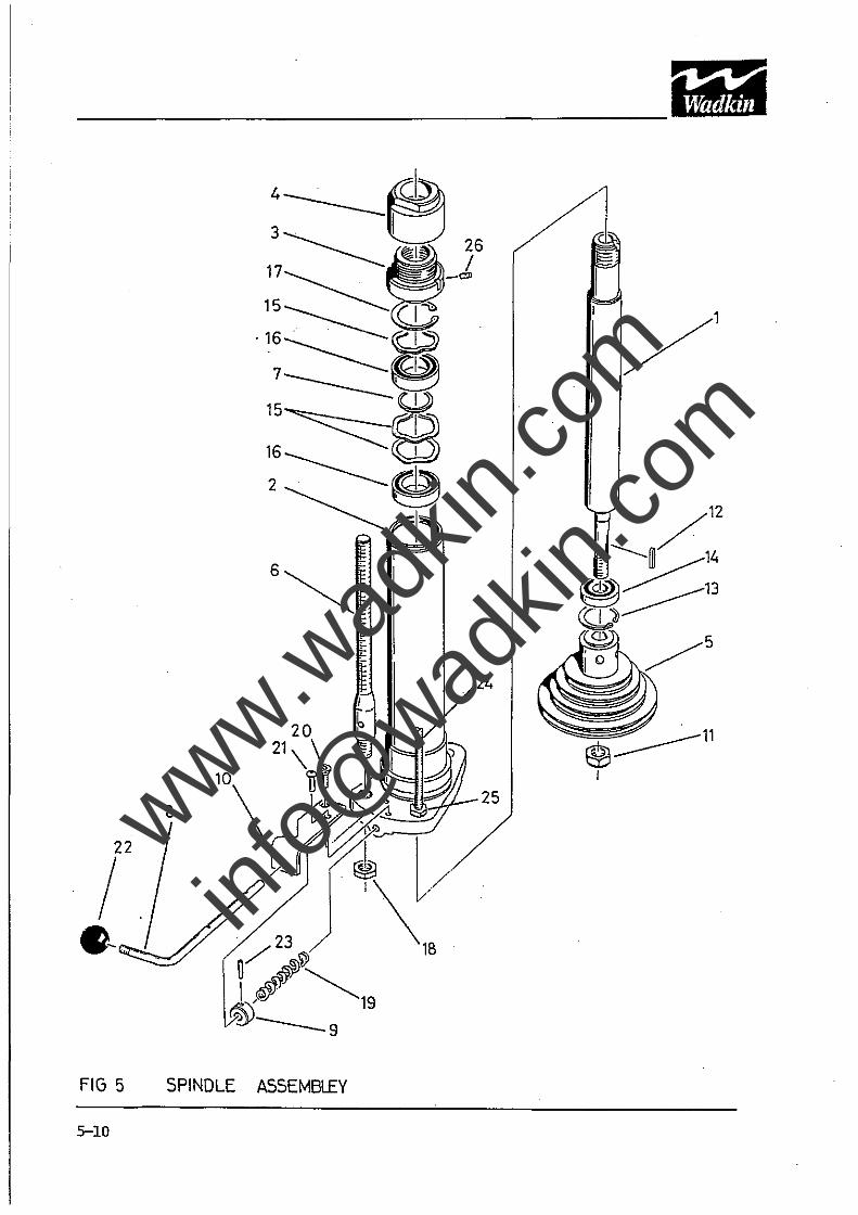
FIG 5 5PINDLE
5-10
4 ____ ~ 3· 0
17 -------. . I1 26 15~ -1, .16~ I'"'"
7~~ 15 W
16~m 2-----~ ~~
I
A55EMBLEY
~:.----11 I
www.wad
kin.co
m
info@
wadkin
.com
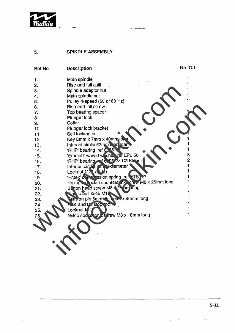
5.
RefNo
1. 2. 3. 4. S. 6. 7. 8. 9. 10. 11. 12. 13. 14. 1S. 16. 17. 18. 19. 20. 21. 22. 23. 24. 2S. 26.
SPINDLE ASSEMBLY
Description No. Off
Main spindle 1 Rise and fall quill 1 Spindle adaptor nut 1 Main spindle nut 1 Pulley 4-speed (SO or 60 Hz) 1 Rise and fall screw 1 Top bearing spacer 1 Plunger lock 1 Collar 1 Plunger lock bracket 1 Self locking nut 1 Key 8mm x 7mm x 40mm long 1 Internal circlip 62mm diameter 1 'RHP' bearing ref 630S-2Z 1 'Emmott' waved washer ref EPl SO 3 'RHP' bearing ref 6008-2Z C3 Kluber 2 Internal circiip 68mm diameter 1 Locknut M20 x 1.Sp 1 'Entex' compression spring ref ETS127 1 Hexagon socket countersunk screw M8 x 2Smm long 1 Button head screw M8 x 2Smm long 1 Plastic ball knob M12 1 Tension pin Smm diameter x 40mm long 1 Rise and fall stop rod 1 Locknut M12 1 Nyloc socket grubscrew M8 x 16mm long 1
5-ll
www.wad
kin.co
m
info@
wadkin
.com
i,y -----------------------------------------
18
17
16
29 ~21 @
4
2,3,19,20
28 0 9
8 /' 18
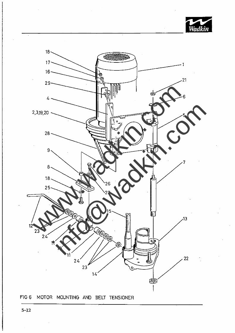
FIG 6 MOTOR MOUNTING AND BELT TENSIONER
5-12
www.wad
kin.co
m
info@
wadkin
.com
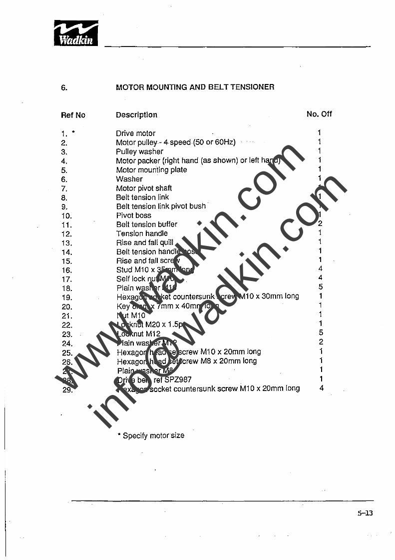
6. MOTOR MOUNTING AND BELT TENSION ER
RefNo Description No. Off
1. • Drive motor 1 2. Motor pulley- 4 speed (50 or 60Hz) 1 3. Pulley washer 1 4. Motor packer (right hand (as shown) or left hand) 1 5. Motor mounting plate 1 6. Washer 1 7. Motor pivot shaft 1 B. Belt tension link 1 9. Belt tension link pivot bush· 1 10. Pivot boss 1
11. Belt tension buffer 2 12. Tension handle 1 13. Rise and fall quill 1
14. Belttension handle boss 1 15. Rise and fall screw 1 16. Stud Ml0 x 35mm long 4
17. Self lock nut M10 4
1B. Plain washer M1 0 5
19. Hexagon socket countersunk screw Ml0 x 30mm long 1
20. Key Bmm x 7mm x 40mm long 1
21. Nut M10 1
22. Locknut M20 x 1.5p 1
23. Locknut M12 5
24. Plain washer M12 2
25. Hexagon head setscrew M10 x 20mm long 1
26. Hexagon head setscrew MB x 20mm long 1
27. Plain washer MB 1
2B. Drive belt rei SPZ987 1
29. Hexagon socket countersunk screw Ml 0 x 20mm long 4
• Specify motor size
5-13
www.wad
kin.co
m
info@
wadkin
.com
8 ________
10
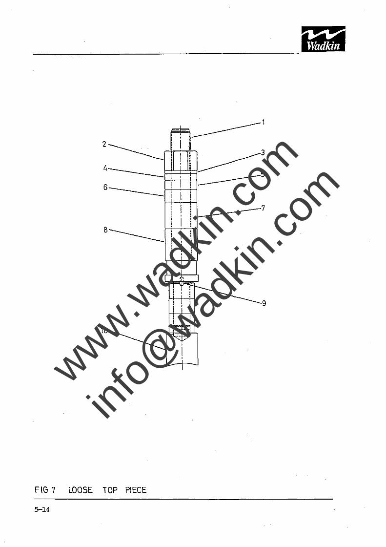
fiG 7 LOOSE TOP PIECE
5-14
i.=Fh ________ 1
, , , .... __ -I-_-J :-__ 't __ ~ '-0:-- --,I .........
-7
9
www.wad
kin.co
m
info@
wadkin
.com
7.
RefNo
1. 2. 3. 4. 5. 6. 7. 8. 9. 10.
LOOSE TOP SPINDLE
Description
Loose spindle Spindle nut 5mm spacer 10mm spacer 15mm spacer 20mm spacer 40mm spacer 50mm spacer Spindle drive dowel Machine main spindle
Note: When ordering any of the above parts specify the loose spindle diameter.
No. Off
1 1 1 1 1 i 1 1 1 1
5-15
www.wad
kin.co
m
info@
wadkin
.com
17 20 21
12
9
rib~l(1(~ll=~~~~$~B~~~)- 4,10 ,----!.lV
18.19 1+1-----7
2,3
________________________________ . ....Lf-l-~1------'~
22 4,5,6 8 1
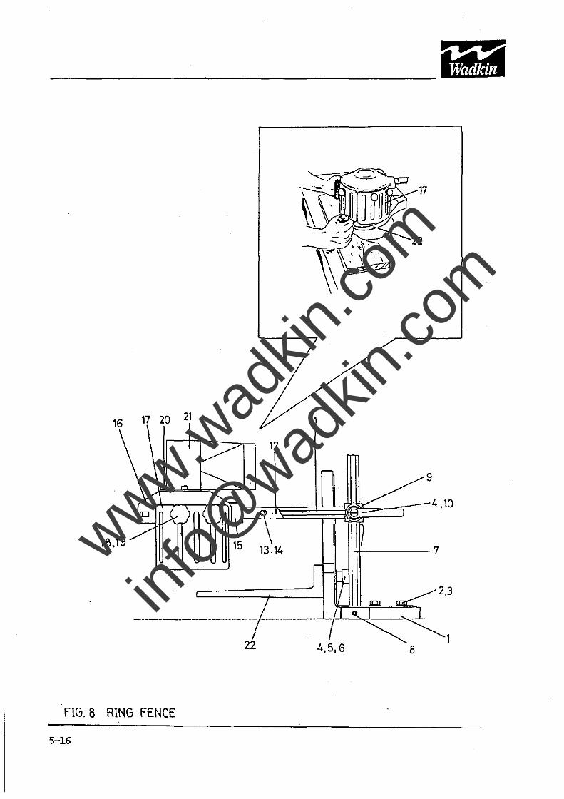
fIG. B RING FENCE
5-l6
www.wad
kin.co
m
info@
wadkin
.com
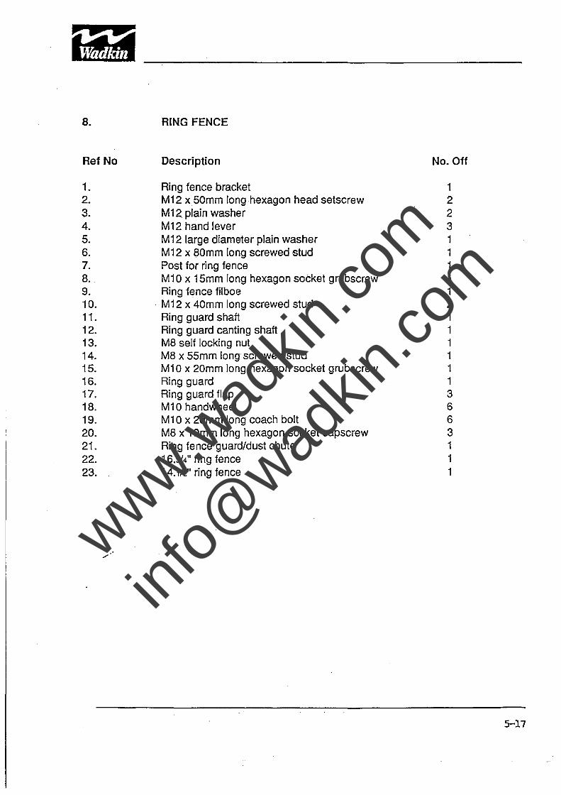
8. RING FENCE
RefNo Description No. Off
1. Ring fence bracket 1 2. M12 x50mm long hexagon head setscrew 2 3. M12. plain washer 2 4. M12 hand lever 3 5. M12 large diameter plain washer 1 6. M12 x BOmm long screwed stud 1 7. Post for ring fence 1 B. M10 x 15mm long hexagon socket grubscrew 1 9. Ring fence filboe 1 10. . M12 x 40mm long screwed stud 2 11. Ring guard shaft 1 12. Ring guard canting shaft 1 13. MB self locking nut 1 14. MB x 55mm long screwed stud 1 15. M10 x 20mm long hexagon socket grubscrew 1 16. Ring guard 1 17. Ring guard flap 3 1B. M10 handwheel 6 19. M10 x 20mm long coach bolt 6 20. MB x 1 Omm long hexagon socket capscrew 3 21. Ring fence guard/dust chute 1 22. 16.314" ring fence 1 23. 14.112" ring fence 1
5-17
www.wad
kin.co
m
info@
wadkin
.com
4
11
---+-12, 3··
5
6 14 2
13
! ! ,EIIT ~ 11 Ill. .
" ~
-0- - ... I .= ~ ~/~
5
9,10 7, 8
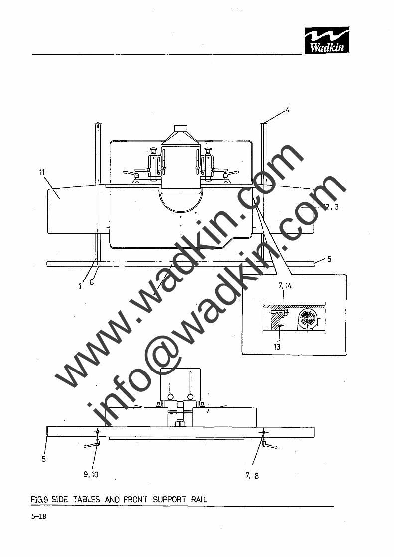
FIG.9 SlOE TABLES AND FRONT SUPPORT RAIL
5-18
www.wad
kin.co
m
info@
wadkin
.com
9.
Ref No
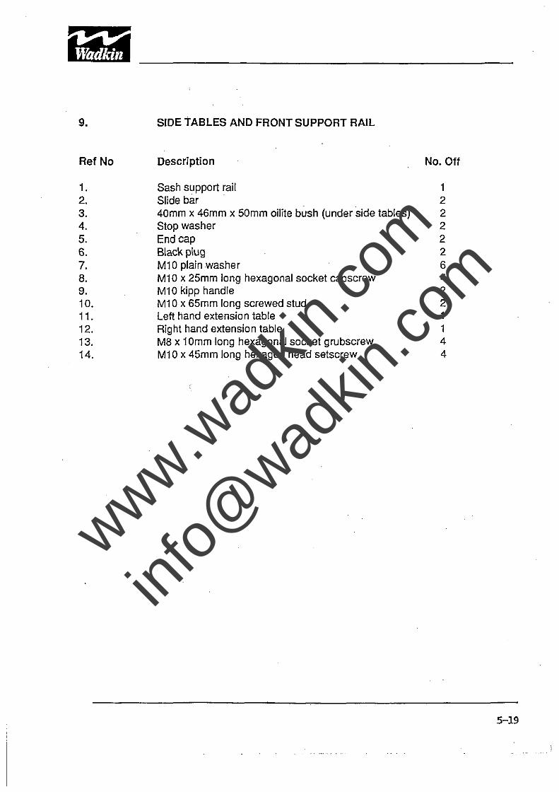
1. 2. 3. 4. S. 6. 7. 8. 9. 10. 11. 12. 13. 14.
SIDE TABLES AND FRONT SUPPORT RAIL
Description No. Off
Sash support rail 1 Slide bar 2 40mm x 46mm x SOmm oHite bush (under side tables) 2 Stop washer 2 End cap 2 Black plug 2 M10plainwasher 6 M10 x 2Smm long hexagonal socket capscrew 4 M10 kipp handle 2 M10 x 65mm long screwed stud 2 Left hand extension table 1 Rig ht hand extensio n table 1 M8 x 1 Omm long hexagonal socket grubscrew 4 M10 x 4Smm long hexagon head setscrew 4
5-19
www.wad
kin.co
m
info@
wadkin
.com
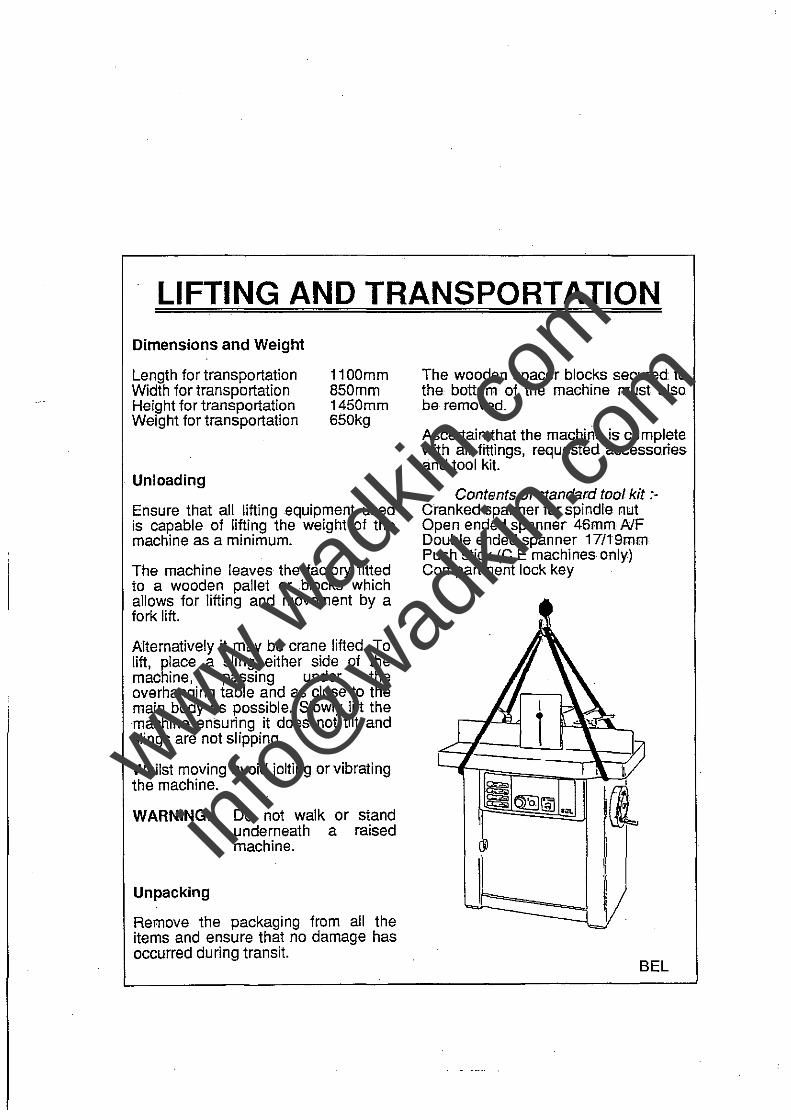
LIFTING AND TRANSPORTATION
Dimensions and Weight
Length for transportation Width for transportation Height for transportation Weight for transportation
. Unloading
1100mm 850mm 1450mm 650kg
Ensure that all lifting equipment used is capable of lifting the weight of the machine as a minimum.
The machine leaves the factory fitted to a wooden pallet or .blocks which allows for lifting and movement by a fork lift.
Alternatively it may be crane lifted. To lift, place a sling either side of the machine, passing under the overhanging table and as close to the main body as possible. Slowly lift the machine ensuring it does not tilt and slings are not slipping.
Whilst moving avoid jolting or vibrating the machine.
WARNING:- Do not walk or stand underneath a raised machine.
Unpacking
Remove the packaging from all the items and ensure that no damage has occurred during transit.
The wooden spacer blocks secured to the bottom of the machine must also be removed.
Ascertain that the machine is complete with all fittings, requested accessories and tool kit.
Contents of standard tool kit :Cranked spanner for spindle nut Open ended spanner 46mm AlF Double ended spanner 17/19mm Push stick (C.E machines only) Compartment lock key
(jJ
I
BEL
www.wad
kin.co
m
info@
wadkin
.com
i~~ -----------------------------------IMPORTANT
SAFETY PROCEDURES AND CONSIDERATIONS
To ensure safe working conditions, persons operating and assisting with the operation of this machine must ensure that they read and fully understand the instructions given within this manual and have received sufficient training in the use 01 the machine and the safety aspects to be observed.
Note:- Persons under the age of 18 years must not operate the machine except during a course of training under the supervision 01 a trained operator.
A) POINTS OF NOTE BEFORE OPERATING OR ASSISTING WITH THE OPERATION OF THE MACHINE
1)
2)
3)
4)
5)
6)
7)
8)
9)
10)
11)
You have read and understood the operation and safety aspects of the machine and have been checked out by a qualified supervisor.
The machine is supplied with full safeguarding. The machine shall not be operated unless the safeguardings suitable to the operation being carried out are in position and functional.
Cutters/blades are the correct type. Suitable for the machine, working conditions and maximum speed, rotate in the correct direction of cut, are sharp and correctly fitted.
Correct spindle, feed speeds are selected for the cutter equipment and working conditions.
Loose clothing is either removed or securely fastened back and jewellery removed.
Adequate working space and lighting is provided.
All dust extraction equipment is switched on, properly adjusted and working adequately.
The machine is securely installed (refer to installation section within this manual).
The machine should only be used for cutting wood or materials with physical and technological characteristics similar to wood and for which the chip or particle removal process is similar.
The correct table rings are selected to close the gap between the table and spindle to a minimum.
Check loose work spindle' is securely and correctly held in position.
www.wad
kin.co
m
info@
wadkin
.com

I"'::I·~ ~itiWI -----------------------------------------------
B) DURING MACHINING:-
1 )
2)
3)
4)
5)
6}
7)
Wear suitable protective clothing e.g., approved eye protection, ear defenders and dust mask. Gloves shall be worn when handling tools and sharp edged feed rolls.
Stop the machine using the emergency stop or at the mains isolator before making adjustments, cleaning or carrying out maintenance.
Keep the floor area around the machine clean and free from wood refuse. Do not allow the floor around the machine to become slippery.
Stop the machine and report immediately to a person in authority any actual or potential malfunction or operator hazard. Do not attempt to repair or rectify the machine unless qualified and authorised to do so.
The operator must not leave the machine running whilst unattended.
Never by pass interlocks.
A handled push block must be used to feed the trailing end of a work piece past the cutting head.
WARNING:-
Failure to observe correct operating procedures prior to and during operation of this machine can result in severe injury.
DO NOT attempt to operate the machine while under the influence of anything that reduces your alertness.
www.wad
kin.co
m
info@
wadkin
.com

Telephone Number: 0870 850 9111 Fax Number: 0870 240 0575
Website: www.wadkin.com Email: [email protected]
www.wad
kin.co
m
info@
wadkin
.com