Embed Size (px)
Citation preview
UWA Design and Construction Standards
Page 1 of 23
Vertical Transport
L DOCUMENT CONTROL
Document Name UWA Design and Construction Standards: Vertical Transport - L
Document Status Final version
Version No. 2.0
Date of Issue 1st June 2020
Endorsement Body To be determined
Owner Director, Campus Management
Author(s)
The Standards have been developed by Campus Management with
the assistance of UWA staff, external consultants, contractors and
colleagues from other education institutions.
Contact Person Associate Director Capital Works, Campus Management
COPYRIGHT
This document is the property of The University of Western Australia and may not be copied as a whole or
in part without the approval in writing of the Associate Director Capital Works, Campus Management.

UWA Design and Construction Standards
Page 2 of 23
Vertical Transport
L Table of Contents
Contents
Introduction .................................................................................................................................. 3
Purpose ......................................................................................................................................... 3
Services ......................................................................................................................................... 3
Related Documents ....................................................................................................................... 4
1.3.1 University Documents ......................................................................................................... 4 1.3.2 Relevant Legislation ............................................................................................................ 4 1.3.3 Manufacturer Specifications and Data Sheets .................................................................... 5 1.3.4 Project Specific Documentation .......................................................................................... 5 Discrepancies ................................................................................................................................ 5
Departures .................................................................................................................................... 5
Professional Services ..................................................................................................................... 6
Structure of Document ................................................................................................................. 6
Definitions ..................................................................................................................................... 6
General Requirements .................................................................................................................. 7
Design Considerations ................................................................................................................... 7
System Functionality ..................................................................................................................... 8
System Types ................................................................................................................................ 8
2.3.1 Lifts – Passenger and Goods ............................................................................................... 8 2.3.2 Escalators and Moving Walks ............................................................................................. 9 Performance Requirements .......................................................................................................... 9
2.4.1 Definition of Terms ............................................................................................................. 9 2.4.2 Traffic Analysis Methodology ............................................................................................. 10 2.4.3 Performance Criteria ........................................................................................................... 11 2.4.4 Car Dimensions and Sizing .................................................................................................. 11 Special Functionality of Systems ................................................................................................... 12
2.5.1 Security Functions ............................................................................................................... 12 2.5.2 Hazardous Goods Operation ............................................................................................... 12 2.5.3 Standby Power Operation ................................................................................................... 13 2.5.4 Passenger Comfort .............................................................................................................. 14 2.5.5 Environmentally Sustainable Design Initiatives .................................................................. 15 2.5.6 Quality, Finishes and Fixtures ............................................................................................. 16 2.5.7 Standards and Codes .......................................................................................................... 17 2.5.8 Safety in Design .................................................................................................................. 17 2.5.9 Testing, Commissioning and Certification ........................................................................... 17 2.5.10 As Installed Documentation and O&M Manuals ................................................................. 18 2.5.11 Maintenance Considerations .............................................................................................. 18
Checklist for Project Team ............................................................................................................ 20
Abbreviations ....................................................................................................................................... 21
References ........................................................................................................................................... 22

UWA Design and Construction Standards
Page 3 of 23
Vertical Transport
L Change Log ........................................................................................................................................... 23
Introduction
PURPOSE
The purpose of this document is to provide an overview of the planning & design principles to be
considered when providing Consultancy and/or Design of Vertical Transportation Services for UWA
projects.
The UWA Design and Construction Standards (the Standards) outline UWA’s expectations for its built
forms to achieve consistency in the quality of the design and construction of those built forms. They are
aligned with the UWA’s Campus Plan 2010 planning principles and UWA’s requisites for aesthetic appeal,
maintainability and environmental sustainability, while ensuring that there is sufficient scope for innovation
and technological advancements to be explored within each project.
The Standards are intended for use by any parties who may be involved in the planning, design and
construction of UWA facilities. This includes external consultants and contractors, UWA planners,
designers and project managers as well as faculty and office staff who may be involved in the planning,
design, maintenance or refurbishment of facilities. These Standards also provide facility managers,
maintenance contractors and other service providers with an understanding of UWA services in order to
assist in the maintenance and operation of facilities.
In the design phase of any project Consultants for Vertical Transportation Services should consider the
best design outcomes, as well as coordination of services and installation. The design should ensure that
all selected building materials and services are fit for purpose whilst providing value for money. Building
materials and services must be of sound construction, offer local support and integrate with other services
and design concepts. Additionally, these materials and services must be easily maintained and able to be
scaled to within the University environment.
SERVICES
The UWA Design and Construction Standards for Vertical Transport (this document) are a part of UWA
Design and Construction Standards set of documents (the Standards). The Standards are divided into the
following service documents for ease of use, but must be considered in its entirety, regardless of specific
discipline or responsibilities:
A Building and Architecture
B Mechanical Services
C Electrical Services

UWA Design and Construction Standards
Page 4 of 23
Vertical Transport
L D Communication Services
E Hydraulic Services
F Security Services
G Fire Services and Fire Safety Engineering
H Structural Works
I Civil Works
J Irrigation Services
K Sustainability
L Vertical Transport (this document)
RELATED DOCUMENTS
1.3.1 University Documents
The Standards are to be read in conjunction with the following relevant University documents:
UWA General Preliminaries Document
UWA Specification for As-Constructed Documentation
Relevant UWA planning and policy documents such as the UWA Campus Plan, UWA Masterplan,
Landscape Vision and Integrated Infrastructure Strategy, University Policy on Alterations to University
Buildings, Asbestos Management Plan, etc.
Relevant UWA operational and maintenance documents such as preferred vendors lists, room data
sheets, operational and maintenance manuals, etc.
Other documents as referenced within the UWA Design and Construction Standards.
1.3.2 Relevant Legislation
The planning, design and construction of each UWA facility must fully comply with current relevant
legislation, including but not limited to:
Relevant Australian or Australian / New Zealand Standards (AS/NZS),
National Construction Code (NCC),
Occupational Safety and Health (OSH) legislation,
Disability Discrimination Act (DDA),
Accessibility Aspiration Design Factors, and
Local council and authority requirements.

UWA Design and Construction Standards
Page 5 of 23
Vertical Transport
L 1.3.3 Manufacturer Specifications and Data Sheets
All installation must be carried out in accordance with manufacturer specifications and data sheets to
ensure product performance over its intended life and so as not to invalidate any warranties.
1.3.4 Project Specific Documentation
Requirements specific to a project, campus or other variable, will be covered by project specific
documentation, such as client briefs, specifications and drawings. These Standards will supplement any
such project specific documentation.
The Standards do not take precedence over any contract document, although they will typically be cross-
referenced in such documentation.
Extracts from the Standards may be incorporated in specifications; however it remains the consultant’s and
contractor’s responsibility to fully investigate the needs of the University and produce designs and
documents that are entirely ‘fit for purpose’ and which meet the ‘intent’ of the project brief.
DISCREPANCIES
The Standards outline the University’s generic requirements above and beyond the above mentioned
legislation. Where the Standards outline a higher standard than within the relevant legislation, the
Standards will take precedence.
If any discrepancies are found between any relevant legislation, the Standards and project specific
documentation, these discrepancies should be highlighted in writing to the Associate Director Capital
Works, Campus Management.
DEPARTURES
The intent of the Standards is to achieve consistency in the quality of the design and construction of the
University’s built forms. However, consultants and contractors are expected to propose ‘best practice /
state of the art’ construction techniques, and introduce technological changes that support pragmatic,
innovative design.
In recognition of this, any departures from relevant legislation, or the Standards, if allowed, must be
confirmed in writing by the Associate Director Capital Works, Campus Management.
Any departures made without such written confirmation shall be rectified at no cost to UWA.
UWA Design and Construction Standards
Page 6 of 23
Vertical Transport
L PROFESSIONAL SERVICES
For all works, it is expected that suitably qualified and experienced professionals are engaged to interpret
and apply these Standards to UWA projects. Works cannot be carried out by unqualified and unlicensed
consultants or contractors.
Campus Management administer the online contractor safety induction. Upon completion the contractor
will be issued with a UWA Contractors Safety Induction Card which they are required to carry at all times
when working for the University.
STRUCTURE OF DOCUMENT
This document is structured into 4 parts:
Part 1 Introduction (this Section)
Part 2 General Requirements – outlines the general requirements or design philosophies adopted
at UWA
Part 3 Checklist for project team (if applicable) – checklist of items for consideration at various
stages of a project
Part 4 Specifications (if applicable) – materials specifications and/or preferred lists for materials,
processes or equipment used by UWA.
DEFINITIONS
For the purpose of this document, the following definitions apply:
Can: Implies a capability of possibility and refers to the ability of the user of the document, or to a
possibility that is available or might occur.
May: Indicates the existence of an option.
Shall: Indicates that a statement is mandatory.
Should: Indicates a recommendation.

UWA Design and Construction Standards
Page 7 of 23
Vertical Transport
L General Requirements
DESIGN CONSIDERATIONS
The design considerations are intended to facilitate the provision of functional spaces which are safe,
comfortable and aesthetically pleasing.
Consistency
Combining system componentry that vary in manufacturer and operating principles may cause
unnecessary complications during maintenance periods.
Within buildings, and across campuses, UWA seek uniformity in systems design, effectively achieving
coherence and compatibility across components both portable and fixed.
Functionality
UWA expect designers to understand the functions of the space and produce designs that practically serve
the intended purpose of the space, permitting simplistic usability for every day operation and maintenance.
Determining logical functionality should involve consideration of several factors including special power
requirements, overall cost and probability of expansion. Preference lies in the delivery of complete cost
effective packages that refrain from over engineering and unnecessary expenditure.
Safety and Maintainability
Maintenance of installed equipment and systems is crucial. Poor maintainability of equipment often leads to
unexpected failures.
Reducing maintenance difficulties and optimising availability of products is essential. Design solutions shall
prioritise safety at all stages from equipment selection through to construction and ongoing operation and
maintenance.
Innovation
Incorporate contemporary technology and innovative engineering for aesthetics and functionality.
Designers should perform life cycle analysis on systems to ensure that selected equipment will last the
expected life of the building and replacement equipment remains available throughout.

UWA Design and Construction Standards
Page 8 of 23
Vertical Transport
L SYSTEM FUNCTIONALITY
Design for buildings should include appropriate means for the vertical connections between various
functional spaces. Such links could be in the form of stairs (open/ feature or enclosed) and ramps as well
as mechanised vertical transportation systems, including passenger and/ or goods lifts, hoists, escalators
and moving walkways. Such vertical transportation systems are critical elements in the operational
efficiency of any building and should be considered together with requirements for issues such as:
Accessibility, Emergency operation and management/ handling of Hazardous Materials. The systems for
UWA buildings should be designed to meet the individual building’s function which may include, but is not
limited to, lecture theatres, teaching and research laboratories, administration buildings and student
accommodation.
SYSTEM TYPES
The vertical transportation systems should provide the following minimum performance criteria.
2.3.1 Lifts – Passenger and Goods
All new lift systems should be machine room-less type selected from the Contractor’s Premium range of
equipment. Passenger elevators are to be located as centrally as possible within each building to provide
efficient and flexible transportation.
New lift systems should provide the following minimum parameters: -
Lift speed selected to provide a nominal terminal to terminal floor travel time of 25 - 30 seconds with a
minimum speed of 1.0 metre per second.
Acceleration and deceleration to be greater than or equal to 0.8 metres per second per second.
For travel distance less than 4 floors the lifts shall provide 180 starts per hour at 40%Elevator Duty
For travel distance greater than 4 floors the lifts shall provide 240 starts per hour at 60% Elevator Duty.
Ride quality commensurate with speed of lift car with lateral and vertical vibrations not greater than the
values as noted in Passenger Comfort criteria below.
Operational noise levels not greater than levels as noted in Passenger Comfort criteria below.
Door operating systems with a minimum lifespan of 6 million cycles

UWA Design and Construction Standards
Page 9 of 23
Vertical Transport
L 2.3.2 Escalators and Moving Walks
Escalators and moving walks should be located as centrally as possible within each building to provide
efficient and flexible transportation. All new escalators and moving walks should be designed with the
following minimum parameters: -
Variable voltage, variable frequency start/stop operation.
Step/pallet width of 1000 mm; reduced width to cater for special situations to UWA approval.
Minimum 800 mm flat transition at top and bottom of units.
Maximum inclination of 30 degrees for escalators and 12 degrees for inclined walks
Speed equal of less than 0.5 metres per second
Yellow step demarcation and skirt brushes to complete length of travel.
Glass balustrades with under handrail continuous LED lighting.
Clear circulation space at both top and bottom of travel with width equal to total unit width and length at
least 2500 mm from handrail newel.
PERFORMANCE REQUIREMENTS
2.4.1 Definition of Terms
Within this design guide the following definitions are referenced:
Interval
Interval is the time between successive lift car arrivals at a floor. The interval can be a measure of the
maximum passenger waiting time for a lift system with adequate handling capacity.
Interval is a design criterion of this guide.
Waiting Time
Waiting time is the period an average passenger will wait between pressing the landing call button and the
lift car arriving.
The waiting time is not a design criterion of this guide, however may be used to demonstrate performance
via simulation.

UWA Design and Construction Standards
Page 10 of 23
Vertical Transport
L Handling Capacity
The handling capacity of the system is the percentage of the assigned building population the lift system
can transport in a five-minute period.
Elevate
Elevate is a commercially available Lift Traffic Analysis software allowing mathematical calculations and
simulation to be undertaken to determine the performance of a lift system in various traffic demands.
2.4.2 Traffic Analysis Methodology
The traffic analysis methodology required to determine the number of lifts required in each building shall be
undertaken using Elevate General Analysis calculations.
The traffic profile applied during General Analysis calculations for two-way traffic peaks shall be as follows:
40% incoming,
40% outgoing and
20% inter-floor.
The traffic profile applied during General Analysis calculations for up peak traffic shall be as follows:
100% incoming,
0% outgoing and
0% inter-floor.
Average Waiting Times
In addition to the General Analysis mathematical calculation undertaken, Elevate simulations may be
required to confirm average waiting times at UWA request.
For any project adopting Destination Control call allocation systems, full simulations shall be undertaken
with the average waiting times to be less than, or equal to, 80% of the nominated intervals.
Prior to completion of schematic design a report should be submitted demonstrating how the performance
requirements of the vertical transportation systems are achieved. The report should include: -
Outline of the assessable population used for traffic analysis calculations/simulations.
Summary of vertical transportation systems proposed to meet the performance requirements of the
UWA Design and Construction Standards
Page 11 of 23
Vertical Transport
L building including speed, number of units, door times, etc.
Summary of key features and special operating requirements of the systems.
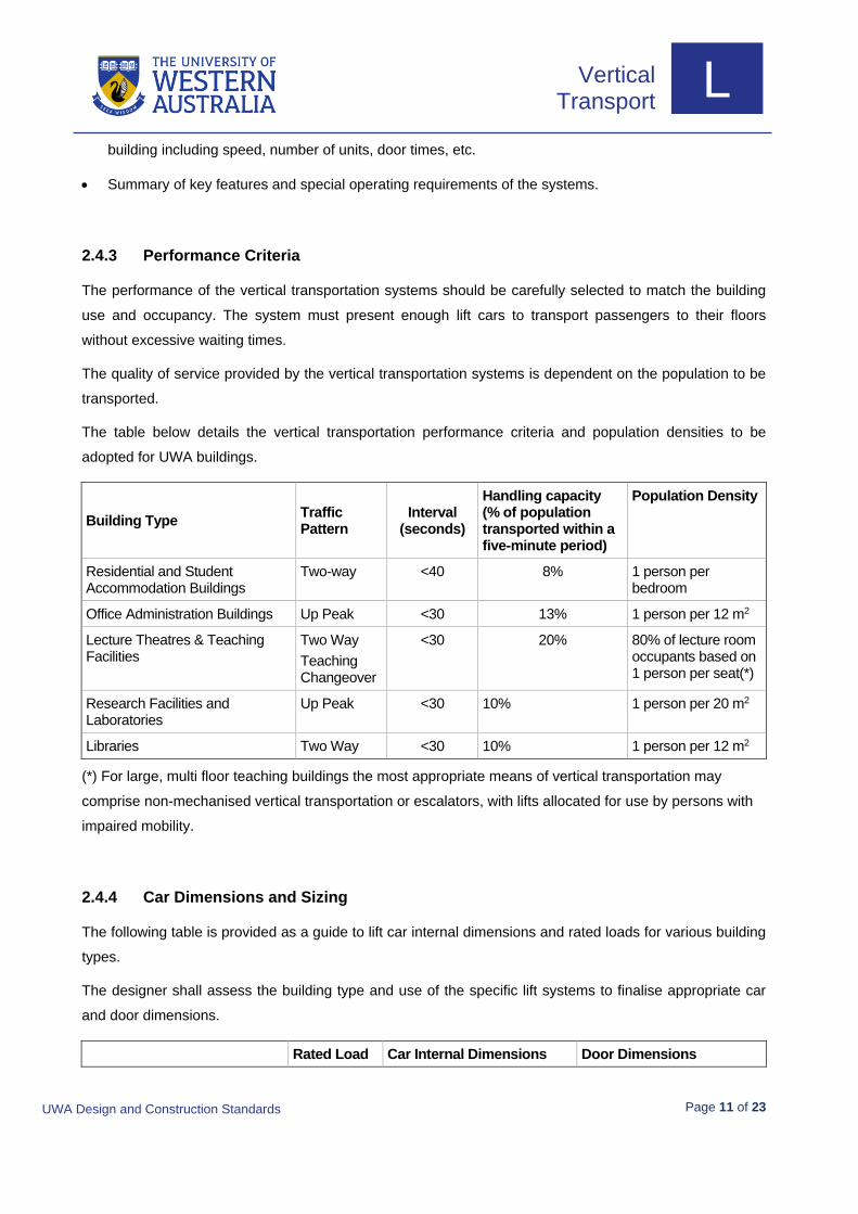
2.4.3 Performance Criteria
The performance of the vertical transportation systems should be carefully selected to match the building
use and occupancy. The system must present enough lift cars to transport passengers to their floors
without excessive waiting times.
The quality of service provided by the vertical transportation systems is dependent on the population to be
transported.
The table below details the vertical transportation performance criteria and population densities to be
adopted for UWA buildings.
Building Type Traffic Pattern
Interval (seconds)
Handling capacity (% of population transported within a five-minute period)
Population Density
Residential and Student Accommodation Buildings
Two-way <40 8% 1 person per bedroom
Office Administration Buildings Up Peak <30 13% 1 person per 12 m2
Lecture Theatres & Teaching Facilities
Two Way
Teaching Changeover
<30 20% 80% of lecture room occupants based on 1 person per seat(*)
Research Facilities and Laboratories
Up Peak <30 10% 1 person per 20 m2
Libraries Two Way <30 10% 1 person per 12 m2
(*) For large, multi floor teaching buildings the most appropriate means of vertical transportation may
comprise non-mechanised vertical transportation or escalators, with lifts allocated for use by persons with
impaired mobility.
2.4.4 Car Dimensions and Sizing
The following table is provided as a guide to lift car internal dimensions and rated loads for various building
types.
The designer shall assess the building type and use of the specific lift systems to finalise appropriate car
and door dimensions.
Rated Load Car Internal Dimensions Door Dimensions

UWA Design and Construction Standards
Page 12 of 23
Vertical Transport
L Rated Load Car Internal Dimensions Door Dimensions
Typical Passenger Lifts
(residential, general access, libraries, etc.)
1275 kg 1400 mm (w) x 2000 mm (d) 1000 mm (w ) x 2100 mm (h)
Higher traffic passenger lifts
(office, lecture theatres, etc.)
1350 kg 1800 mm (w) x 1450 mm (d) 1100 mm (w ) x 2100 mm (h)
Goods Service Lifts 2000 kg 1750 mm (w) x 2000 mm (d) 1300 mm (w ) x 2100 mm (h)
Minimum ceiling height in the lift car shall be selected to match materials transportation requirements as
well as building heights and aesthetic considerations. Passenger car heights should not be less than
2300 mm to the car false ceiling and goods lifts should not be less than 2500 mm to the car false ceiling.
SPECIAL FUNCTIONALITY OF SYSTEMS
2.5.1 Security Functions
Dependant on the building location and type, the vertical transportation systems may require functionality
to improve the building’s security. The security interface should be fully programmable and appropriate for
the building usage with the following minimum guidelines applied: -
The vertical transportation designer must review and coordinate with the Security Design and
Construction Guidelines for the projects requirements.
All car reader systems should be flush mounted within the car operating panel or landing button
faceplates to ensure damage cannot occur.
Where security key switches are used for isolation of floors the keys should be of a high security type
approved by UWA.
Where destination control systems are adopted the security card readers shall allow all functions of the
system to be used.
Particular attention should be made to ensure that the vertical transportation system does not compromise
building security.
2.5.2 Hazardous Goods Operation
Where goods service lifts require transport of Hazardous Goods the lift shall be provided with the following
functionality.
Key switches should be located on each landing call station and within each car operating panel.
Car ventilation systems shall be specifically designed for the type of hazardous goods to be transported

UWA Design and Construction Standards
Page 13 of 23
Vertical Transport
L with appropriate car/shaft sensor systems for alarm purposes.
The sequence below provided as an indicative typical arrangement for a duplex car group. This principle of
operation should be adopted and modified as required for the specific installation.
Loading floor – Off Loading floor – On Loading floor – Run
Receiving floor – off Lifts operate normally One lift is removed from duplex control and recalled to the loading floor, parks with doors open and illuminates an indicator at all landings and in the car with 'Lift on Hazardous Goods Control'. Existing car calls to be completed first
Call is entered in lift car then doors close and lift is dispatched to receiving floor and parks with doors closed. If safety edge is activated, doors reopen and car does not move until a further run command is entered at the key switch
Receiving floor – on One lift is removed from duplex control and recalled to loading floor and parks with doors open and illuminates an indicator at all landings and in the car 'Lift on Hazardous Goods Control'. Existing car calls to be completed first
Lift already on hazard goods control remains parked at first activated level and second switch activation is ignored. Only one lift is to be allowed to enter hazard goods control at any time
Lift that is parked in response to run signal from loading floor opens doors for unloading
Receiving floor – run Call is entered in lift car then doors close and lift is dispatched to Level 1 and parks with doors closed. If safety edge is activated, doors reopen and car does not move until a further run command is entered at the key switch
Lift that is parked in response to run signal from loading floor opens doors for unloading
Lift remains parked with doors open after unloading signal from on/run combination – ignores second run command
2.5.3 Standby Power Operation
Where the project is provided with a standby generator, the lifts should be connected to the standby power
source in accordance with the Electrical Services design principles. In most cases it would be expected
that the standby generator would provide standby power to at least one lift in the building in the event of
power failure. The basic sequence of the operation for such is expected to comprise the following:
On the loss of mains power supply the standby generator shall automatically start up and supply
standby power
All lifts shall sequentially return at rated speed to the main entrance. One lift only in any group at any
one time may be selected to return to the main floor

UWA Design and Construction Standards
Page 14 of 23
Vertical Transport
L All lifts shall illuminate the lift returning to main floor indicator until the respective lift has arrived at the
main floor
Following automatic recall of all lifts to the main floor, the lift selected shall remain in operational at full
rated speed.
Automatic Recall Operation
Unless provided with emergency power via a standby generator, every lift should be provided with an
appropriate automatic system (UPS or similar) that will recall the lift to the nearest floor in the event of a
power failure provided the lift is safe to travel.
The lift shall travel to the nearest floor and open the doors to release any trapped passengers whilst
retaining lift car lighting and ventilation systems.
2.5.4 Passenger Comfort
Ride Quality
All lifts cars shall offer a smooth travel to passengers. The quality of ride shall be measured in accordance
with the techniques outlined in ISO 18738 and all reporting provided using ISO weighting.
The maximum permissible horizontal and vertical accelerations shall not exceed:
Half amplitude peak acceleration
Adjacent peak to peak acceleration
All lifts 7.5 milli-g 15 milli-g
Lift Sound Levels
Based on a maximum ambient sound level of 45dB(A) in lobbies and occupied space adjacent to lift wells,
the operating average peak sound levels shall be:
Inside car, stationary at any floor, fan off, doors closed: 45dB(A)
Inside car, running, accelerating or decelerating, fan off: 55 dB(A)
During door opening, closing or reversal sequences, fan off: 55dB(A)
At the top floor landing with the lift starting or running 10dB(A)
Inside machine rooms with lifts operating: 75dB(A)
Outside lift well or machine room with lift operating: 48dB(A).

UWA Design and Construction Standards
Page 15 of 23
Vertical Transport
L
Communication and Alarm Monitoring
All lifts should be provided with hands-free auto dialling emergency communication systems
connecting directly to the Security Control Room.
2.5.5 Environmentally Sustainable Design Initiatives
The following environmentally sustainable design initiatives shall be implemented for the project:
Machines
Hoist machines should be specified as permanent magnet synchronous type. The high efficiency of these
machines results in reduced energy consumption when compared to traditional lift and escalator systems.
Power Drives/Motion Controllers
The drives for both escalators and lifts should be specified as Variable Voltage Variable Frequency (VVVF)
systems. The VVVF drives will reduce starting current and energy consumption throughout the lift of the
equipment. All VVVF drives installed shall selected with consideration of minimisation of harmonic content
reflected into the supply mains, refer to the Design and Construction Standards – Electrical Services.
The lift control system must have no “time bombs” or software lock outs and if specialised tooling is
required to maintain the lifts this must be supplied by the lift company so that others can maintain the
equipment.
Lighting Systems
It is proposed that lighting systems on lift systems be LED type with improved energy efficiency over
traditional lighting systems.
The car interior lighting on the lift system should be specified to ‘time out’ and switch off after a period of
inactivity.
Energy Saving “Time Out”
In addition to the lighting system timing out the car indication screens and ventilation systems should be
specified to switch off after a period of inactivity.

UWA Design and Construction Standards
Page 16 of 23
Vertical Transport
L
2.5.6 Quality, Finishes and Fixtures
Finishes for floor, walls and ceilings in lift cars, doors and door frames, plus arrangement of appointments
and fixtures should be selected appropriate for the functioning of the lifts. In general, finishes and fixtures
should be hard wearing to withstand the intended building use incorporating vandal resistant materials with
emphasis on ease of cleaning, maintenance and aesthetics. Emphasis should be given to panel design
and profile in all lifts that will not only discourage vandalism but also complement the planning
consideration of the project and provide user friendliness. Preference should be given to selection of
standard proprietary products (not bespoke) that can be readily replaced and maintained throughout the life
of the building.
All lift cars that may be used for transportation of materials should be provided with removable protective
blankets.
If a destination control system (DCS) is not used then general operational controls (car operating panels)
within the lift should considered to be provided on both sides of the lift car for ease of operation by all
users. The car operating panels must comply with AS1735.12-1999 regarding disabled access design and
feature dual illumination and touch tone button identification.
The main car operating panel must incorporate a key switch for independent service operation and a key
switch for fire service operation.
As a minimum requirement LED type car displays must be installed in the car operating panels however,
consideration should be made for the provision of colour displays that are connected to the University IT
system and capable of displaying variable student information and the like.
Programmable visual and audible voice type annunciators should be incorporated into lifts along with
hands free auto dialling emergency communication systems that are connected to UWA security. The auto
dial phone shall incorporate “inductive loop technology” and must provide communication from the top of
the lift car and the lift pit.
Lift car emergency lighting systems should ensure safe and re-assuring lift car environment under loss of
power conditions and incorporate backup power for the emergency alarm system.
Lighting and emergency lighting fitting selections should be identical to the provisions installed under the
general Electrical Services installation.
To maximise passenger protection at door entrances, three dimensional multiple infra-red non-contact
beam systems should be utilised.
Power outlet should be incorporated into the lift car for utility maintenance and cleaning purposes.
Landing direction / arrival lanterns should be provided with adjustable electronic chimes and tone direction
UWA Design and Construction Standards
Page 17 of 23
Vertical Transport
L identification (one chime for up and two chimes for down). Hall lanterns shall have an advance notification
time that is adjustable but set at 4.0 seconds. At a minimum a digital display shall be provided at the main
landing above each landing door.
A hall fire service key switch must be incorporated into the main exit hall lobby plate, this key switch barrel
is to match the barrel in the car fire service key switch.
2.5.7 Standards and Codes
New vertical transportation systems must comply with all relevant Australian Standards, National
Construction Code, WA Electrical Requirements, WA Electricity Act 1945 and Work Health and Safety
Requirements (Public Buildings) Regulations.
For compliance with Australian Standard AS 1735 Part 1, all passenger lifts shall comply with EN 81.20
and EN 81.50 and all escalators and walks shall comply with EN 115.
Applicable Standards include (but are not limited to) those listed within the References section of this
document. Standards listed should be reviewed for current versions and additional amendments.
2.5.8 Safety in Design
Incorporate design solutions that minimises the potential for danger during construction as well as during
occupation and maintenance.
Regular reviews shall be undertaken progressively through the various stages of design to facilitate optimal
solutions to minimise unsafe risk issues. The opportunity for UWA staff to be involved in such workshops
and reviews shall be provided.
2.5.9 Testing, Commissioning and Certification
Prior to practical completion, testing and commissioning shall be performed on all installed equipment and
systems to verify that they operate correctly and function as intended.
Testing and commissioning shall include:
Testing required by the Statutory Authority
Testing of each element and service to establish it performs correctly in each operating mode,
including operating sequences and interlocks
Review of arrangements for operation, servicing and maintenance to ensure that they are adequate for

UWA Design and Construction Standards
Page 18 of 23
Vertical Transport
L UWA needs
Results should be incorporated into the As Installed documentation and handed over as part of Practical
Completion.
Inspections
The University reserves the right to carry out inspections during the course of construction and to
undertake tests on completed installations.
Witness testing may be required for various testing and commissioning activities.
2.5.10 As Installed Documentation and O&M Manuals
All projects shall be completed with the handover of As Built documentation detailing all information
necessary to enable safe and efficient ongoing operation and maintenance of the new installation. In some
cases, this documentation may need to take the form of upgrading existing documents. All such As Built
documentation shall include the following information as a minimum:
Operation instructions
Contact details and schedule for all spare and replacement parts
Maintenance manuals, testing registers and schedules
Well plan, pit plans, elevations, car interior drawings and fixtures drawings.
Electrical Safety Certificate
It is a requirement of Occupational Safety and Health Regulations-1996, regulation 4.30.1 (c) that
this documentation is available at the Workplace. A copy must be left with the lift or escalator.
Refer UWA Specifications for As-Constructed Documentation for further information.
2.5.11 Maintenance Considerations
Maintenance of UWA facilities is funded from recurrent resources that usually bear little relation to the
capital programme making it imperative to ensure that all Vertical Transportation equipment is constructed
bearing in mind life-cycle costs and maintainability.
Designs will be rejected if they opt for minimising capital cost at the expense of on-going maintenance
costs or make inadequate provision for:
• servicing and maintenance

UWA Design and Construction Standards
Page 19 of 23
Vertical Transport
L • uncomplicated removal and replacement of plant and equipment
• access
• durability
Sample maintenance procedures for Vertical Transportation throughout the buildings are vital and shall be
reviewed with UWA prior to tendering.
All design and construction materials shall reflect low maintenance considerations. Fabric, structural and
service components shall be readily accessible to reduce labour requirements and down-time should
repairs be required post defects liability.
Consultants shall ensure that they indicate:
• how each item of plant is to be installed initially;
• how the University’s routine service personnel will access each plant item;
• methodology to be used in changing the largest item of plant in any plant area.
“Adequate access” for routine servicing means the sufficient space for a service technician, irrespective of
working age, to reach all items requiring routine service safely and without undue stress.
Mechanical and Electrical plant and equipment, particularly those requiring manual operation or routine
maintenance. shall have safe and comfortable access. Adequate clearances are essential to enable work
to be carried out around them.
Adequate space in conduits or ducts to allow for future growth of services shall be allowed. Such things as
electrical and telephone cables may be too big and heavy to be pulled around conduit bends; straight
access, without bends or obstructions, shall be provided.

UWA Design and Construction Standards
Page 20 of 23
Vertical Transport
L Checklist for Project Team
The following activities should be considered by the project team during the planning of the project.
Activity Responsibility Stakeholder(s) Timeframe
Building planning/ vertical transportation philosophy
Architect/ vertical transportation consultant
CM (Engineering Services / Client Faculty)
Gate 2 Feasibility
Spatial planning requirements/ ergonomic analysis
Architect/ vertical transportation consultant
CM (Engineering Services)
Gate 2 Feasibility
BCA and regulatory compliance issues
Architect/ vertical transportation consultant
CM (Engineering Services)
Gate 2 Feasibility
System interfaces with BMCS, fire, emergency power, security and CCTV
Vertical transportation and other services consultants
CM (Engineering Services/ Building Operations)
Gate 3 Planning/ detailed design
Shaft ventilation, in car air conditioning, hazardous goods alarms
Vertical transportation and mechanical services consultants
CM (Engineering Services/ Building Operations)
Gate 3 Planning/ detailed design
Interior design coordination/ buildability
Architect/ vertical transportation consultant
CM (Engineering Services)
Gate 3 Planning/ detailed design
Ongoing (post DLP) maintenance agreement
Vertical transportation consultant
CM (Engineering Services)
Gate 4 Tender
Beneficial use of lift for construction activities
Contractor CM (Engineering Services)
Gate 5 Construction

UWA Design and Construction Standards
Page 21 of 23
Vertical Transport
L Abbreviations
ANSI American National Standards Institute
ATS Automatic Transfer Switches
BMCS Building Management and Control Systems
CCTV Closed Circuit Television
CM Campus Management
DLP Defects Liability Period
EN European (Normalised) Standards
ESD Ecologically Sustainable Design
ISO International Organisation for Standardisation
LED Light Emitting Diode
UWA The University of Western Australia
VVVF Variable Voltage Variable Frequency

UWA Design and Construction Standards
Page 22 of 23
Vertical Transport
L References
AS 1170.4 Structural design actions Earthquake actions in Australia
AS 1735 Series (all parts) Lifts, Escalators & Moving Walks
AS/NZS 3000 Wiring Rules
AS/NZS 61000 Electromagnetic compatibility (EMC)
EN 81 Safety Rules for the construction and installation of lifts – Lifts for the
transport of persons and goods
Part 20: Passenger and goods passenger lifts
Part 50: Design rules, calculations, examinations and test of lift components
EN 115 Safety of escalators and moving walks
Part 1 Construction and installation
ISO 18738 Measurement of lift ride quality
NCC National Construction Code of Australia
WAER WA Electrical Requirements

UWA Design and Construction Standards
Page 23 of 23
Vertical Transport
L
Change Log
It is envisaged that revisions to this document will be undertaken at intervals of not more than two (2)
years. This version differs from the previous version in the following areas:
Section Title Description
1.6 Professional Services Inclusion of safety induction.
2.3.1 Lifts – Passenger and Goods Additional text regarding the positioning of lifts
2.3.2 Escalators and Moving Walks Additional text regarding the positioning of escalators and moving walk ways
2.4.4 Car Dimensions and Sizing Additional text regarding passenger car heights
2.5.5. Power Drives/Motion Controllers Additional paragraph regarding lift control systems
2.5.6 Quality, Finishes and Fixtures Substantial update regarding car operating panels
2.5.10 As Installed Documentation and O&M Manuals Updates on safety compliance
2.5.11 Maintenance Considerations New paragraph on maintenance considerations