Embed Size (px)
Citation preview
1
Installation Guide & Owner’s Manual
Water Source Heat Pumps Vertical / Horizontal 1 – 5 Nominal Ton
GEOCOOL SERIES
Reader should pay particular attention to the words: NOTE, CAUTION, and WARNING. NOTES are intended to clarify or make the installation easier. CAUTIONS are given to prevent equipment damage. WARNINGS are given to alert reader that personal injury and/or equipment damage may result if installation and/or service are not handled properly.
Rev. 042012001
Table of Contents
1. Description General
Feature Overview
Safety
2. Installation General
Codes and Ordinance
Handling
Location
Service and Installation Clearance
Mounting and Suspension
Duct Work
Sealing
Supplementary Cooling / Heating
Water Line Piping
Condensate Piping
Electrical
Filters
Enhanced Dehumidification
Control Wiring
Thermostat Wiring Diagram
3. Completion General
Check‐out
Start‐up
Commissioning
4. Operation and Maintenance General
Maintenance and Schedule
Filters
Blower Assembly
Indoor Coil(s)
Water Heat Exchanger
Service
5. Troubleshooting 6. Appendix 1 – Unit Configuration 7. Appendix 2 – Model Number Nomenclature
3
The equipment is protect‐ed by a standard limited warranty under the cond‐ition that initial installat‐ion, service, start‐up and maintenance is performed according to their instru‐
ction set forth in this manual. This manual should be read in its entirety prior to installation and before performing any service or maintenance work. Equip‐ment description in this manual is available with various optional accessories. If you have questions after reading this manual in its entirety, consult other factory documentation or contact your sales representative to obtain further information before manipulating this equipment or its optional accessories. This unit must not be used at any time during any phase of construction. Very low return temperatures, harmful vapors and misplacement of the filters will damage the unit and its efficiency.
1. Description
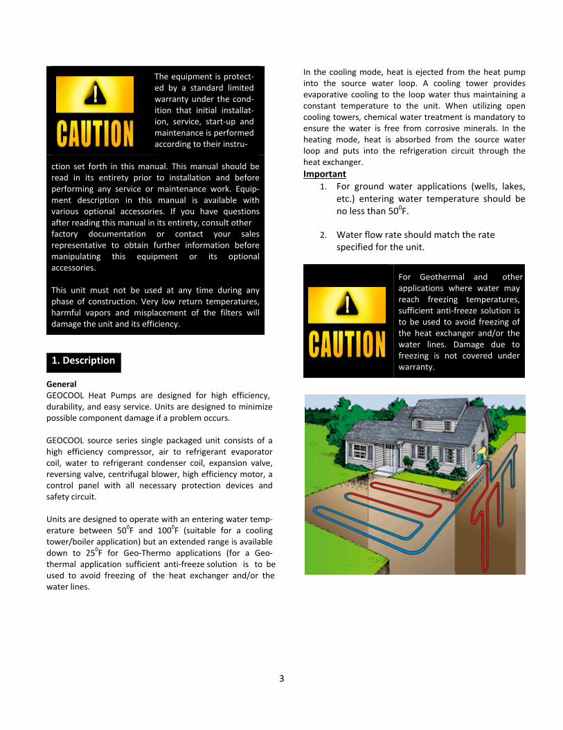
General GEOCOOL Heat Pumps are designed for high efficiency, durability, and easy service. Units are designed to minimize possible component damage if a problem occurs. GEOCOOL source series single packaged unit consists of a high efficiency compressor, air to refrigerant evaporator coil, water to refrigerant condenser coil, expansion valve, reversing valve, centrifugal blower, high efficiency motor, a control panel with all necessary protection devices and safety circuit. Units are designed to operate with an entering water temp‐erature between 500F and 1000F (suitable for a cooling tower/boiler application) but an extended range is available down to 250F for Geo‐Thermo applications (for a Geo‐thermal application sufficient anti‐freeze solution is to be used to avoid freezing of the heat exchanger and/or the water lines.
In the cooling mode, heat is ejected from the heat pump into the source water loop. A cooling tower provides evaporative cooling to the loop water thus maintaining a constant temperature to the unit. When utilizing open cooling towers, chemical water treatment is mandatory to ensure the water is free from corrosive minerals. In the heating mode, heat is absorbed from the source water loop and puts into the refrigeration circuit through the heat exchanger.
Important 1. For ground water applications (wells, lakes,
etc.) entering water temperature should be no less than 500F.
2. Water flow rate should match the rate specified for the unit.
For Geothermal and other applications where water may reach freezing temperatures, sufficient anti‐freeze solution is to be used to avoid freezing of the heat exchanger and/or the water lines. Damage due to freezing is not covered under warranty.
4
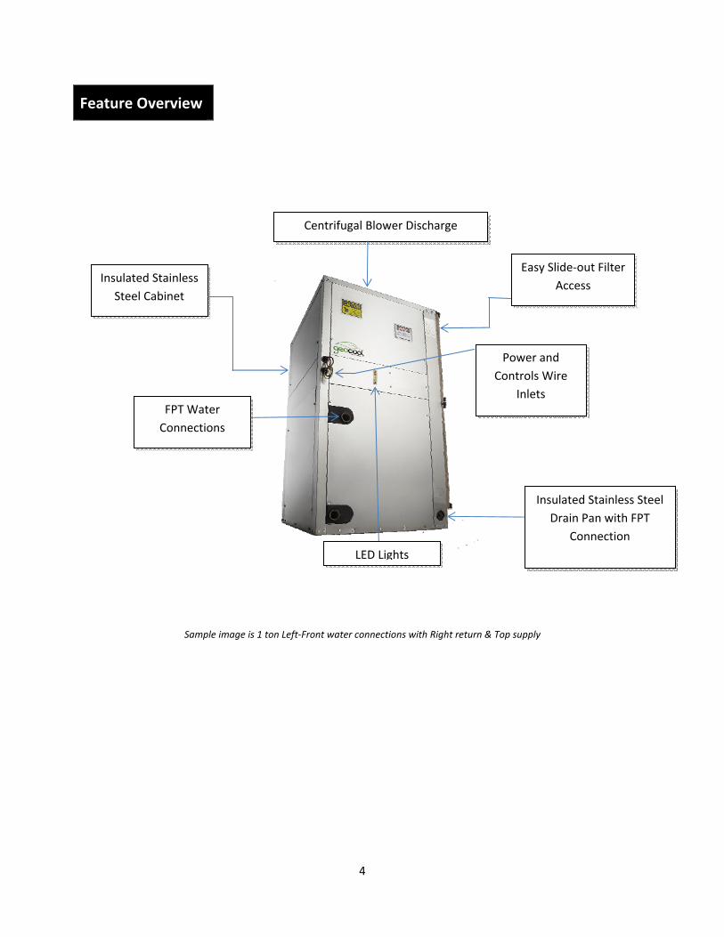
Feature Overview
Sample image is 1 ton Left‐Front water connections with Right return & Top supply
Centrifugal Blower Discharge
Easy Slide‐out Filter
Access Insulated Stainless
Steel Cabinet
Insulated Stainless Steel
Drain Pan with FPT
Connection
FPT Water
Connections
Power and
Controls Wire
Inlets
LED Lights
5
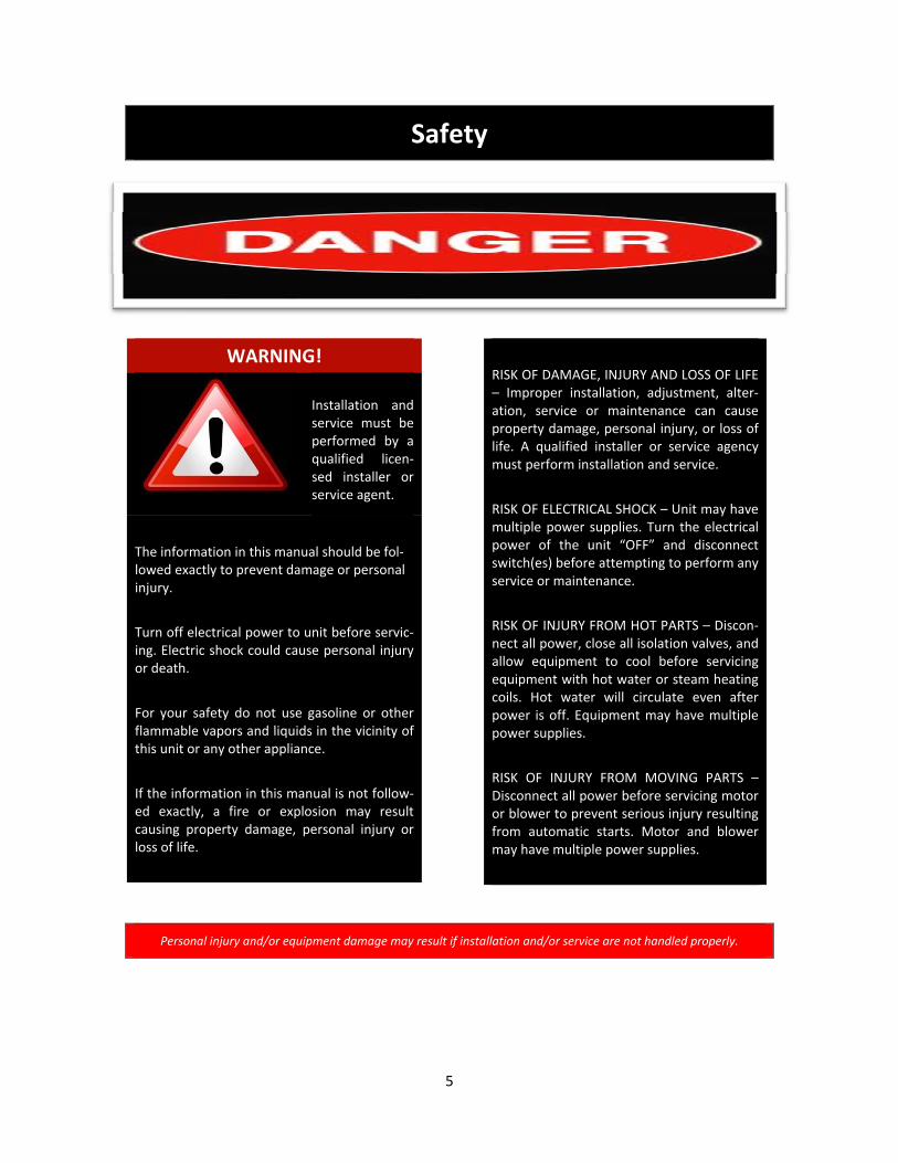
Safety
WARNING!
Installation and service must be performed by a qualified licen‐sed installer or service agent.
The information in this manual should be fol‐lowed exactly to prevent damage or personal injury.
Turn off electrical power to unit before servic‐ing. Electric shock could cause personal injury or death.
For your safety do not use gasoline or other flammable vapors and liquids in the vicinity of this unit or any other appliance.
If the information in this manual is not follow‐ed exactly, a fire or explosion may result causing property damage, personal injury or loss of life.
RISK OF DAMAGE, INJURY AND LOSS OF LIFE – Improper installation, adjustment, alter‐ation, service or maintenance can cause property damage, personal injury, or loss of life. A qualified installer or service agency must perform installation and service.
RISK OF ELECTRICAL SHOCK – Unit may have multiple power supplies. Turn the electrical power of the unit “OFF” and disconnect switch(es) before attempting to perform any service or maintenance.
RISK OF INJURY FROM HOT PARTS – Discon‐nect all power, close all isolation valves, and allow equipment to cool before servicing equipment with hot water or steam heating coils. Hot water will circulate even after power is off. Equipment may have multiple power supplies.
RISK OF INJURY FROM MOVING PARTS – Disconnect all power before servicing motor or blower to prevent serious injury resulting from automatic starts. Motor and blower may have multiple power supplies.
Personal injury and/or equipment damage may result if installation and/or service are not handled properly.
7
specific design of the system and the unit.
Flexible connectors are required on all duct connections to minimize air leaks.
Closed loop and pond applications require specialized design knowledge. No attempt at these installations should be made unless the dealer has received specialized training.
WARNING!
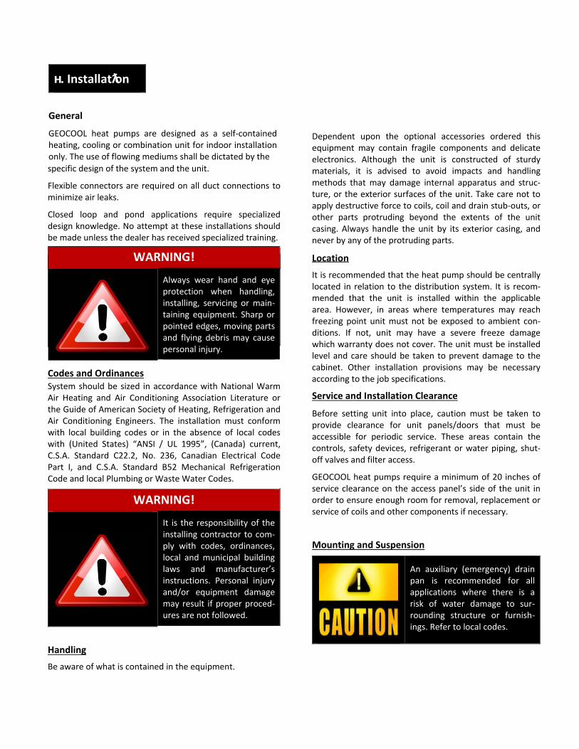
Always wear hand and eye protection when handling, installing, servicing or main‐taining equipment. Sharp or pointed edges, moving parts and flying debris may cause personal injury.
Codes and Ordinances System should be sized in accordance with National Warm Air Heating and Air Conditioning Association Literature or the Guide of American Society of Heating, Refrigeration and Air Conditioning Engineers. The installation must conform with local building codes or in the absence of local codes with (United States) “ANSI / UL 1995”, (Canada) current, C.S.A. Standard C22.2, No. 236, Canadian Electrical Code Part I, and C.S.A. Standard B52 Mechanical Refrigeration Code and local Plumbing or Waste Water Codes.
WARNING!
It is the responsibility of the installing contractor to com‐ply with codes, ordinances, local and municipal building laws and manufacturer’s instructions. Personal injury and/or equipment damage may result if proper proced‐ures are not followed.
Handling
Be aware of what is contained in the equipment.
Dependent upon the optional accessories ordered this equipment may contain fragile components and delicate electronics. Although the unit is constructed of sturdy materials, it is advised to avoid impacts and handling methods that may damage internal apparatus and struc‐ture, or the exterior surfaces of the unit. Take care not to apply destructive force to coils, coil and drain stub‐outs, or other parts protruding beyond the extents of the unit casing. Always handle the unit by its exterior casing, and never by any of the protruding parts.
Location
It is recommended that the heat pump should be centrally located in relation to the distribution system. It is recom‐mended that the unit is installed within the applicable area. However, in areas where temperatures may reach freezing point unit must not be exposed to ambient con‐ditions. If not, unit may have a severe freeze damage which warranty does not cover. The unit must be installed level and care should be taken to prevent damage to the cabinet. Other installation provisions may be necessary according to the job specifications.
Service and Installation Clearance
Before setting unit into place, caution must be taken to provide clearance for unit panels/doors that must be accessible for periodic service. These areas contain the controls, safety devices, refrigerant or water piping, shut‐off valves and filter access.
GEOCOOL heat pumps require a minimum of 20 inches of service clearance on the access panel’s side of the unit in order to ensure enough room for removal, replacement or service of coils and other components if necessary.
Mounting and Suspension
An auxiliary (emergency) drain pan is recommended for all applications where there is a risk of water damage to sur‐rounding structure or furnish‐ings. Refer to local codes.
н. Installatƛon
General
GEOCOOL heat pumps are designed as a self‐contained heating, cooling or combination unit for indoor installation only. The use of flowing mediums shall be dictated by the
7
Floor Mounted
Make sure the unit is level and mounted on a field‐supplied platform and rubber pads with a minimum height to ensure proper fall on the condensate line. A slope of no less than 2% is recommended. Other installation provisions may be necessary according to job specifications.
Suspended
The GEOCOOL horizontal water source heat pump is equipped with steel hanging mounts for suspended installations. The unit should be lifted into position by supporting the unit with the skid used for shipping. Suspend the unit from its four corners with field supplied 3/8 “all‐thread” rods. Secure the rods into the holes in the steel hanging mounts and secure with nuts and lock‐washers.
Duct Work
For new installations duct work should be designed and installed using current ASHRAE procedures which take into consideration proper air‐flow, proper distribution, sound level considerations, efficiency, durability, safety, etc.
For existing duct systems please make sure unit fits the duct system in the aspects of flow rate, pressure drop, insulation and sound level. Any air leaks in existing system should be found and repaired.
Flexible connectors are important for connections of unit to metal ductwork to eliminate transfer of vibrations. Duct‐work should be properly insulated to avoid energy loss and condensation during the cooling cycle.
Sealing
It is very important to keep outside air from infiltrating the unit cabinet. Seal all piping penetrations with Armaflex, Permagum, or other suitable sealant. Also seal around drain connections, electrical connections, and all other inlets where air may enter the cabinet. This is especially important when the unit is installed in an unconditioned area.
Supplementary Cooling / Heating
When heat is called for, unit shall switch to mechanical heating. Should the unit have hot water, or steam capabilities, it shall be activated according to controls.
Unit with Hot Water Coil
Water supply lines must be insulated, properly fastened, drained and supported according to the local code require‐ments.
Unit with Steam Coils
The unit MUST be installed high enough to allow for a minimum of one (1) foot condensate drop leg off of the steam coil (or as recommended by the steam trap manu‐facturer). Lines should be insulated with approved insulat‐ion and be properly fastened, sloped and supported according to local code requirements.
Unit with Water‐Side Economizer
Water supply lines must be insulated with closed cell type pipe insulation or insulation that includes a vapor barrier. Lines should be properly fastened, drained and supported according to local code barriers.
Water Line Piping
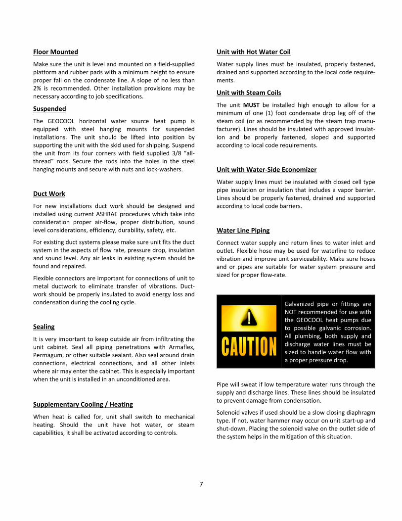
Connect water supply and return lines to water inlet and outlet. Flexible hose may be used for waterline to reduce vibration and improve unit serviceability. Make sure hoses and or pipes are suitable for water system pressure and sized for proper flow‐rate.
Galvanized pipe or fittings are NOT recommended for use with the GEOCOOL heat pumps due to possible galvanic corrosion. All plumbing, both supply and discharge water lines must be sized to handle water flow with a proper pressure drop.
Pipe will sweat if low temperature water runs through the supply and discharge lines. These lines should be insulated to prevent damage from condensation.
Solenoid valves if used should be a slow closing diaphragm type. If not, water hammer may occur on unit start‐up and shut‐down. Placing the solenoid valve on the outlet side of the system helps in the mitigation of this situation.
8
Caution: Inadequate water flow to heat exchanger due to improper pipes, valves or pump is dangerous to heat pump and constitutes abuse that will void the warranty of the compressor and/or heat exchanger.
An in‐line water screen strainer is always recommended but it is imperative where poor water quality may exist. Ball valves with hose connections are recommended for back‐flushing and chemical cleaning of the evaporator condenser.
Condensate Piping
A drain trap must be connected to the drain pan at the unit. A condensate connection is provided on each side of the unit. Condensate piping should be installed according to local codes. The line should be one size larger than pipe size as the drain nipple and should pitch downward toward the building drain.
Do not over tighten the connections. The connection to the unit needs to be hand tightened.
Connect drain line to the unit with a “P” trap to avoid pulling air from outside th e unit back through the drain line. The line should be insulated where the ambient conditions may cause a condensation on the surface of the pipe. An additional drain pan may be installed under the unit, and should include a separate drain line for overflow from the primary drain. An air break should be used with long runs of condensate lines.
Drain pans in any air conditioning equipment, even when they have a built‐in slope to the drain, will have moisture present and will require periodic cleaning to prevent any build‐up of algae or bacteria. Cleaning of the drain pans will also prevent any possible plugging of the drain lines, and overflow of the pan itself. Some means to clean out the “P” trap should be provided. Only qualified personnel should clean drain pans, drain lines or the insides of equipment.
Electrical
WARNING!
All electrical installations need to be performed by a licensed electrician and according to all applicable codes.
Check the unit data plate to make sure it matches with the power supply. Proper fuses or HACR circuit breakers should be installed. See unit’s nameplate for minimum amps and maximum fuse/breaker. Connect power to the unit according to the wiring diagram provided with the unit.
Use ONLY copper wires for power lines.
The power and control wiring may be brought into unit through the holes provided on the unit’s cabinet. Protect the branch circuit in accordance with code requirements.
GEOCOOL control wires should not run with any other wires inside same conduit.
The units must be electrically grounded in accordance with all applicable codes.
Power can be applied to the unit after the control wiring is connected, and start‐up checks are complete.
Filters
Slide the correct filter in with arrow pointing towards the blower in the direction of airflow. Make sure filter(s) cover the entire coil(s).
9
Enhanced Dehumidification
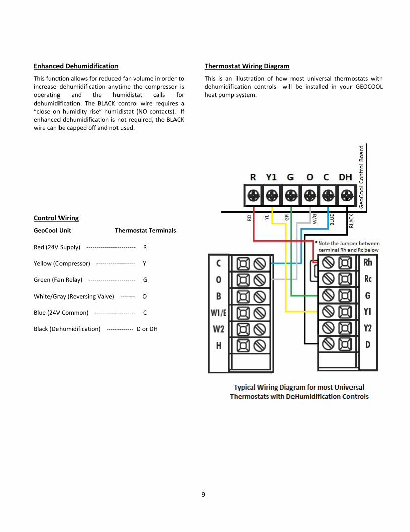
This function allows for reduced fan volume in order to increase dehumidification anytime the compressor is operating and the humidistat calls for dehumidification. The BLACK control wire requires a “close on humidity rise” humidistat (NO contacts). If enhanced dehumidification is not required, the BLACK wire can be capped off and not used.
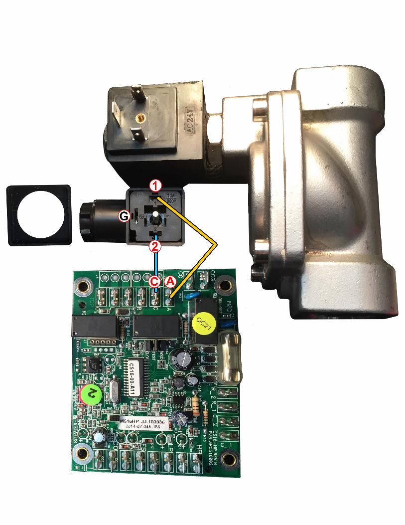
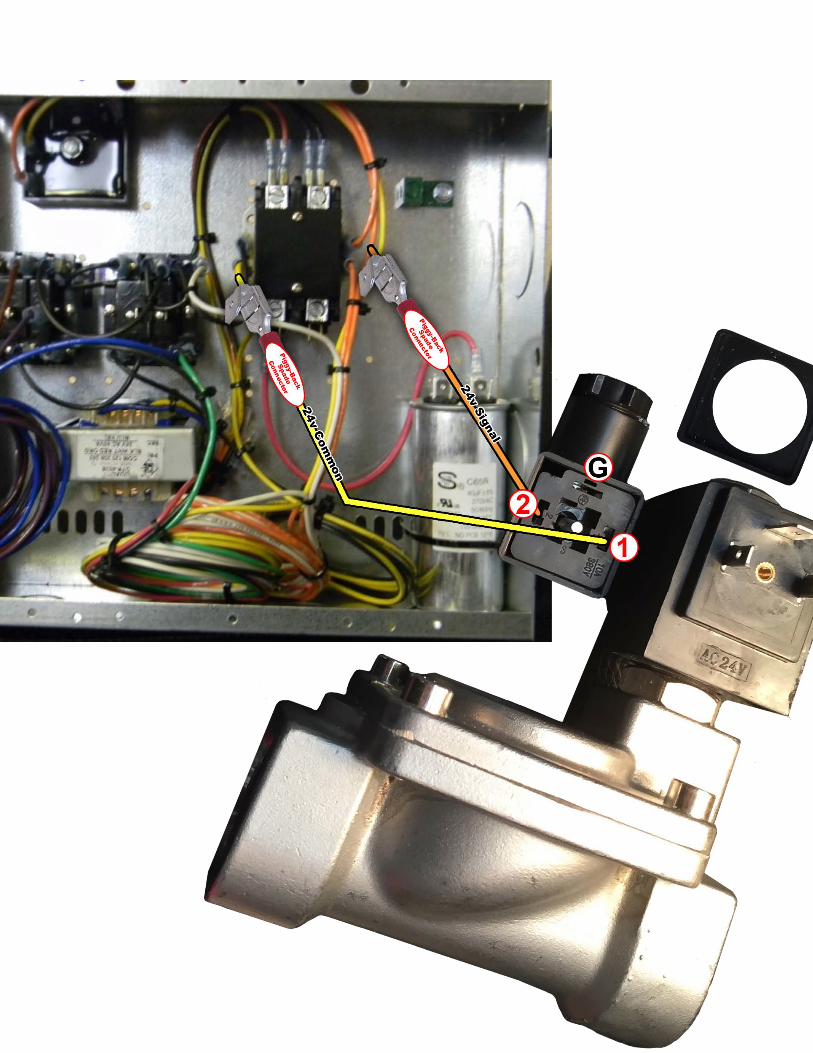
Control Wiring
GeoCool Unit Thermostat Terminals Red (24V Supply) ‐‐‐‐‐‐‐‐‐‐‐‐‐‐‐‐‐‐‐‐‐‐‐‐ R Yellow (Compressor) ‐‐‐‐‐‐‐‐‐‐‐‐‐‐‐‐‐‐‐ Y Green (Fan Relay) ‐‐‐‐‐‐‐‐‐‐‐‐‐‐‐‐‐‐‐‐‐‐‐ G White/Gray (Reversing Valve) ‐‐‐‐‐‐‐ O Blue (24V Common) ‐‐‐‐‐‐‐‐‐‐‐‐‐‐‐‐‐‐‐‐ C Black (Dehumidification) ‐‐‐‐‐‐‐‐‐‐‐‐‐ D or DH
Thermostat Wiring Diagram
This is an illustration of how most universal thermostats with dehumidification controls will be installed in your GEOCOOL heat pump system.
10
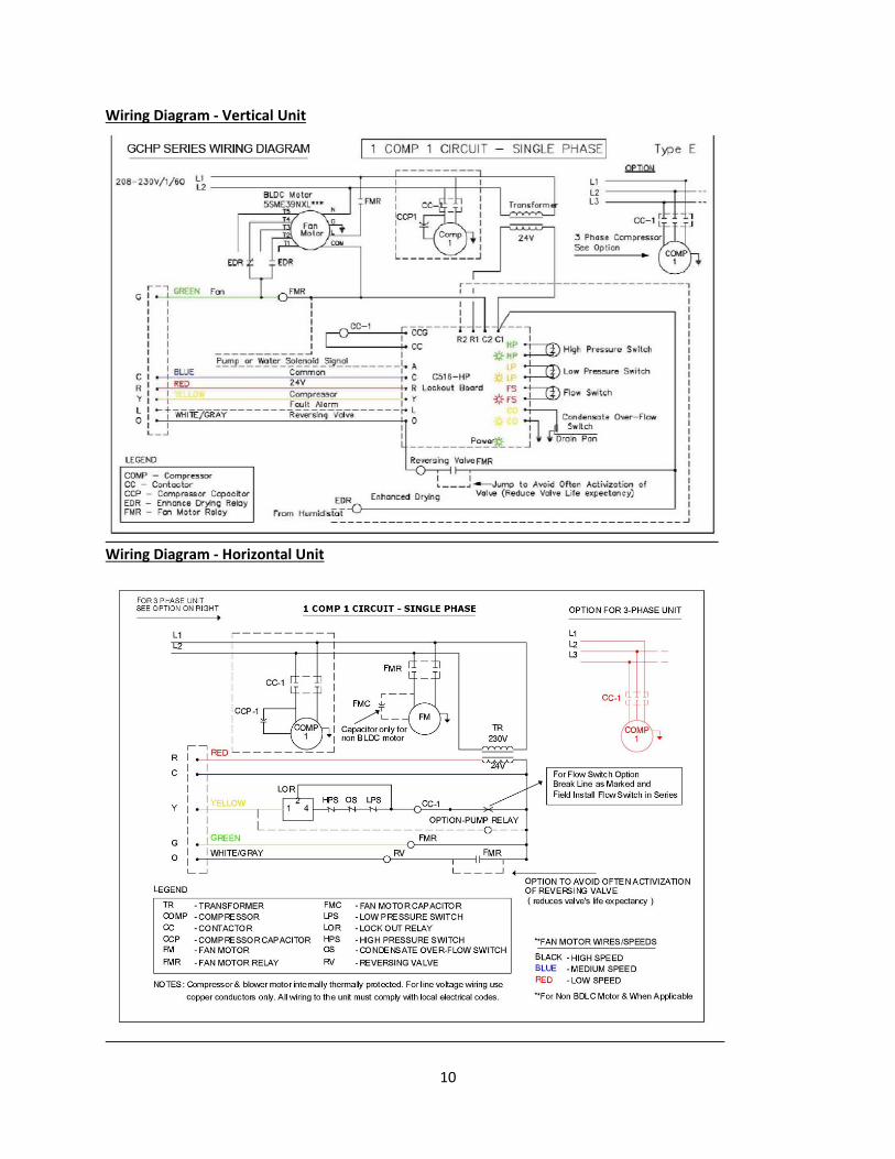
Wiring Diagram ‐ Vertical Unit
Wiring Diagram ‐ Horizontal Unit
13
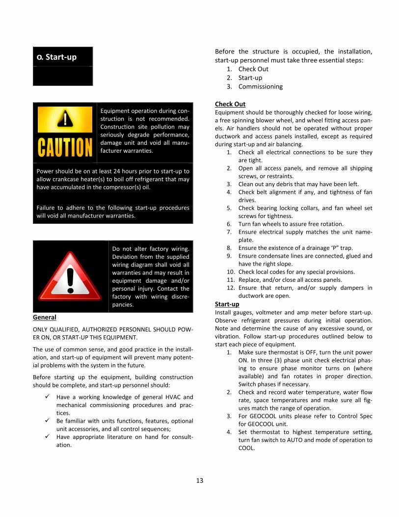
о. Start‐up
Equipment operation during con‐struction is not recommended. Construction site pollution may seriously degrade performance, damage unit and void all manu‐facturer warranties.
Power should be on at least 24 hours prior to start‐up to allow crankcase heater(s) to boil off refrigerant that may have accumulated in the compressor(s) oil.
Failure to adhere to the following start‐up procedures will void all manufacturer warranties.
Do not alter factory wiring. Deviation from the supplied wiring diagram shall void all warranties and may result in equipment damage and/or personal injury. Contact the factory with wiring discre‐pancies.
General
ONLY QUALIFIED, AUTHORIZED PERSONNEL SHOULD POW‐ER ON, OR START‐UP THIS EQUIPMENT.
The use of common sense, and good practice in the install‐ation, and start‐up of equipment will prevent many potent‐ial problems with the system in the future.
Before starting up the equipment, building construction should be complete, and start‐up personnel should:
Have a working knowledge of general HVAC and mechanical commissioning procedures and prac‐tices.
Be familiar with units functions, features, optional unit accessories, and all control sequences;
Have appropriate literature on hand for consult‐ation.
Before the structure is occupied, the installation, start‐up personnel must take three essential steps:
1. Check Out 2. Start‐up 3. Commissioning
Check Out Equipment should be thoroughly checked for loose wiring, a free spinning blower wheel, and wheel fitting access pan‐els. Air handlers should not be operated without proper ductwork and access panels installed, except as required during start‐up and air balancing.
1. Check all electrical connections to be sure they are tight.
2. Open all access panels, and remove all shipping screws, or restraints.
3. Clean out any debris that may have been left. 4. Check belt alignment if any, and tightness of fan
drives. 5. Check bearing locking collars, and fan wheel set
screws for tightness. 6. Turn fan wheels to assure free rotation. 7. Ensure electrical supply matches the unit name‐
plate. 8. Ensure the existence of a drainage ‘P” trap. 9. Ensure condensate lines are connected, glued and
have the right slope. 10. Check local codes for any special provisions. 11. Replace, and/or close all access panels. 12. Ensure that return, and/or supply dampers in
ductwork are open.
Start‐up Install gauges, voltmeter and amp meter before start‐up. Observe refrigerant pressures during initial operation. Note and determine the cause of any excessive sound, or vibration. Follow start‐up procedures outlined below to start each piece of equipment.
1. Make sure thermostat is OFF, turn the unit power ON. In three (3) phase unit check electrical phas‐ing to ensure phase monitor turns on (where available) and fan rotates in proper direction. Switch phases if necessary.
2. Check and record water temperature, water flow rate, space temperatures and make sure all fig‐ures match the range of operation.
3. For GEOCOOL units please refer to Control Spec for GEOCOOL unit.
4. Set thermostat to highest temperature setting, turn fan switch to AUTO and mode of operation to COOL.
14
5. Make sure reversing valve is energized but neither fan nor compressor is running.
6. Reduce temperature setting to about five (5) deg‐rees below room temperature. Fan should start immediately and compressor shall start after about three (3) minutes. In a unit with two (2) circuits second compressor shall start about three (3) minutes after first one has started.
7. Verify unit is cooling. 8. Turn system mode to HEAT and then set tempera‐
ture to about five (5) degrees above room temp‐erature. Compressor shall stop and then start after about three (3) minutes. In a unit with two (2) circuits second compressor shall start about three (3) minutes after the first one has started.
9. Verify unit is heating. 10. Set the thermostat to the desired temperature. 11. Instruct customer on the unit, the thermostat ope‐
ration and the required maintenance.
12. Record all pressures, flow rates and temperatures related to operation.
Optional Equipment / Accessory
Any optional equipment and/or accessory which may come with the unit must be checked according to its specificat‐ions.
Commissioning
The commissioning of an air‐conditioning system is the pro‐cess of achieving, verifying and documenting the perform‐ance of that system to meet the operational needs of the building. This may not be the formal process in smaller structures, such as a normal residence, but some form of owner acceptance will occur. Adjustments made during the commissioning phase may include air or water balancing or configuration of controls and operational sequences.
Air Balancing
The correct air balancing is imperative to achieve optimal comfort and efficiency of the entire system. Unqualified personnel should not attempt to adjust air circulation, as all systems have unique operating characteristics. Professional air balance specialists should be employed to establish actual
operating conditions and to configure the air delivery sys‐tem for optimal performance.
Water Balancing
When unit is one of many at the same water system, a specialist with a complete working knowledge of water systems, controls and operation must be employed to properly balance the entire system. Unqualified personnel should not attempt to manipulate temperatures, pressures or flow rates, as all systems have unique operating charac‐teristics and improper balancing can result in undesirable noises and operation.
пΦ Operation and Maintenance
General
A heat pump is a self ‐contained system that requires prof‐esssional maintenance and repair. Other than replacing filters and keeping the exterior and surrounding areas of the unit clean, the homeowner should not attempt to make any adjustments or repairs to the heat pump system. A qualified licensed technician will be able to take care of any questions or problems which may occur.
For either maintenance routine or in the event the unit is not functioning correctly a service company is required. Only a company with service technicians qualified and experienced in both heating and air conditioning should be permitted to service the systems in order to keep warrant‐ies in effect. The service tech may call the factory if assist‐ance is required.
After start‐up the air conditioning system requires a main‐tenance schedule.
A maintenance program similar to the example given be‐low should be scheduled for routine maintenance of this equipment in order to provide continued efficient and re‐liable operation for the owner.
Maintenance Schedule
Monthly:
Check cleanliness of filters and replace if necess‐ary.
15
Inspect coils, clean if dirty or obstructed in any way.
In case of excessive noise or unusual operation check for reason and act accordingly.
Quarterly: Check cooling coil drain pan and accessible conden‐
sate pipes and “P” trap to assure proper drainage. Clean if necessary.
Check operation of heating and cooling section if seasonal.
Check the inlet and outlet air temperatures. Deter‐mine cause for abnormal changes and act accord‐ingly.
Check water pressure drop to determine water flow, in case flow rate is out of range adjust water flow with unit’s valves.
Annually: Inspect and clean unit interior as necessary at the
beginning of cooling season mode. Clean the drain line, “P” trap, and condensate pan. Clean evaporator coil. Clean the water to refrigerant heat exchanger. Check refrigerant pressures and temperatures
every spring and correct unusual operation accord‐ingly.
Filters When the heat pump circulates and filters the air in your house, dust and dirt particles build up on the filter. Exces‐sive accumulation can block the airflow, forcing the unit to work harder to maintain desired temperatures, thus costing more. Check filter at least once a month and change as needed with the same size filter. Filters on GEOCOOL heat pump units are easy to change as they slide out of side of unit easily. Replace old filters with the size indicated on each filter or as shown in the specific unit data. Be sure arrows on filter frames point toward the unit.
Blower Assembly GEOCOOL heat pumps use forward curved blower wheels that are non‐overloading, very efficient and very easy clean. Clean blower wheels are necessary to reduce electrical use, maintain capacity and reduce stress on the unit. The blower wheel and blower section need to be inspected periodically, and cleaned of dust and debris. To inspect and clean the blower, set thermostat to “OFF” position turn the electrical power to the unit to “OFF” position at the disconnect switch. Clean the assembly, check for looseness, check screws for tightness, rotate blower wheel while listening close for noise or roughness.
Indoor Coils
Coils should be inspected and cleaned annually to ensure there is no obstruction to airflow. Dirty evaporator coils will eventually freeze up, and often result in time consum‐ing and expensive service call. Clean filters will help to pre‐vent dirt from accumulating on the evaporator; however the evaporator should be cleaned annually with a soft bristled brush and steam or a non‐corrosive coil cleaning solution. Move the brush in the fin direction. Make sure coil fins are not flattened.
Water Heat Exchanger
The efficiency of the unit is dependent on the water to refrigerant heat exchanger’s performance. Therefore, a clean heat exchanger and a correct flow rate are impera‐tive for minimizing the cost of operation. In severe cases dirty heat exchanger or flow rate out of range may cause the unit to malfunction. Heat exchanger can be cleaned by back flushing with or without the appropriate chemical available at a refrigeration supply shop. To obtain the correct flow rate adjust the water line valves.
NOTE
It is important to keep filters, water heat exchanger, coil and blower(s) clean.
Service
Phone: 800.360.1569 Fax: 270.443.9606
Be sure to have the model and serial number of the unit available when calling the warranty service department. These model and serial numbers will help them answer questions regarding your unit.
16
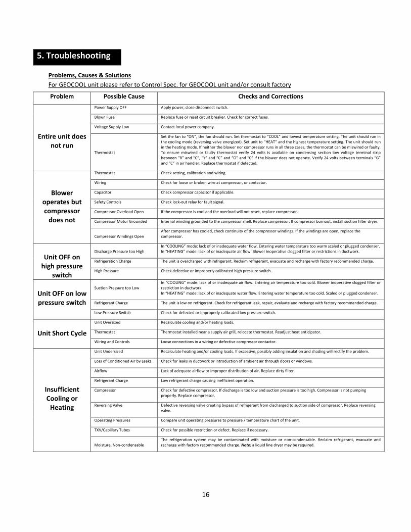
5. Troubleshooting
Problems, Causes & Solutions
For GEOCOOL unit please refer to Control Spec. for GEOCOOL unit and/or consult factory
Problem Possible Cause Checks and Corrections
Entire unit does
not run
Power Supply OFF Apply power, close disconnect switch.
Blown Fuse Replace fuse or reset circuit breaker. Check for correct fuses.
Voltage Supply Low Contact local power company.
Thermostat
Set the fan to “ON”, the fan should run. Set thermostat to “COOL” and lowest temperature setting. The unit should run in the cooling mode (reversing valve energized). Set unit to “HEAT” and the highest temperature setting. The unit should run in the heating mode. If neither the blower nor compressor runs in all three cases, the thermostat can be miswired or faulty. To ensure miswired or faulty thermostat verify 24 volts is available on condensing section low voltage terminal strip between “R” and “C”, “Y” and “C” and “O” and “C” if the blower does not operate. Verify 24 volts between terminals “G” and “C” in air handler. Replace thermostat if defected.
Blower operates but compressor does not
Thermostat Check setting, calibration and wiring.
Wiring Check for loose or broken wire at compressor, or contactor.
Capacitor Check compressor capacitor if applicable.
Safety Controls Check lock‐out relay for fault signal.
Compressor Overload Open If the compressor is cool and the overload will not reset, replace compressor.
Compressor Motor Grounded Internal winding grounded to the compressor shell. Replace compressor. If compressor burnout, install suction filter dryer.
Compressor Windings Open
After compressor has cooled, check continuity of the compressor windings. If the windings are open, replace the compressor.
Unit OFF on high pressure
switch
Discharge Pressure too High
In “COOLING” mode: lack of or inadequate water flow. Entering water temperature too warm scaled or plugged condenser. In “HEATING” mode: lack of or inadequate air flow. Blower inoperative clogged filter or restrictions in ductwork.
Refrigeration Charge The unit is overcharged with refrigerant. Reclaim refrigerant, evacuate and recharge with factory recommended charge.
High Pressure Check defective or improperly calibrated high pressure switch.
Unit OFF on low pressure switch
Suction Pressure too Low
In “COOLING” mode: lack of or inadequate air flow. Entering air temperature too cold. Blower inoperative clogged filter or restriction in ductwork. In “HEATING” mode: lack of or inadequate water flow. Entering water temperature too cold. Scaled or plugged condenser.
Refrigerant Charge The unit is low on refrigerant. Check for refrigerant leak, repair, evaluate and recharge with factory recommended charge.
Low Pressure Switch Check for defected or improperly calibrated low pressure switch.
Unit Short Cycle
Unit Oversized Recalculate cooling and/or heating loads.
Thermostat Thermostat installed near a supply air grill, relocate thermostat. Readjust heat anticipator.
Wiring and Controls Loose connections in a wiring or defective compressor contactor.
Insufficient Cooling or Heating
Unit Undersized Recalculate heating and/or cooling loads. If excessive, possibly adding insulation and shading will rectify the problem.
Loss of Conditioned Air by Leaks Check for leaks in ductwork or introduction of ambient air through doors or windows.
Airflow Lack of adequate airflow or improper distribution of air. Replace dirty filter.
Refrigerant Charge Low refrigerant charge causing inefficient operation.
Compressor Check for defective compressor. If discharge is too low and suction pressure is too high. Compressor is not pumping properly. Replace compressor.
Reversing Valve Defective reversing valve creating bypass of refrigerant from discharged to suction side of compressor. Replace reversing valve.
Operating Pressures Compare unit operating pressures to pressure / temperature chart of the unit.
TXV/Capillary Tubes Check for possible restriction or defect. Replace if necessary.
Moisture, Non‐condensable
The refrigeration system may be contaminated with moisture or non‐condensable. Reclaim refrigerant, evacuate and recharge with factory recommended charge. Note: a liquid line dryer may be required.