Embed Size (px)
Citation preview

VERTICAL TOOL TURRETS (VTP)
Instruction Manual 1
VERTICAL
TOOL TURRETS
INSTRUCTION MANUAL
VTP-250 VTP-200 VTP-160
March 2009

2
VERTICAL TOOL TURRETS (VTP)
Instruction Manual
VERTICAL TOOL TURRETS (VTP)
Instruction Manual 3
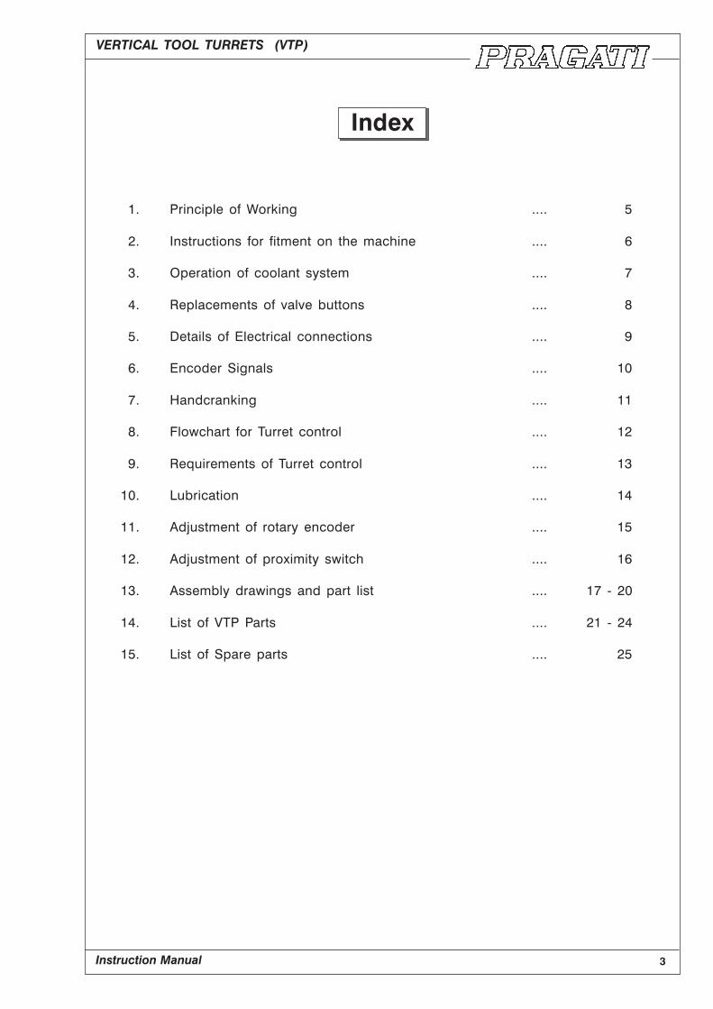
Index
1. Principle of Working .... 5
2. Instructions for fitment on the machine .... 6
3. Operation of coolant system .... 7
4. Replacements of valve buttons .... 8
5. Details of Electrical connections .... 9
6. Encoder Signals .... 10
7. Handcranking .... 11
8. Flowchart for Turret control .... 12
9. Requirements of Turret control .... 13
10. Lubrication .... 14
11. Adjustment of rotary encoder .... 15
12. Adjustment of proximity switch .... 16
13. Assembly drawings and part list .... 17 - 20
14. List of VTP Parts .... 21 - 24
15. List of Spare parts .... 25

4
VERTICAL TOOL TURRETS (VTP)
Instruction Manual

VERTICAL TOOL TURRETS (VTP)
Instruction Manual 5
1. Principle of Working
Three piece face gear is the basic element used for indexing. Coupling design allows the turret
body to be indexed without lifting. It also ensures high repeat positioning accuracy as well as
rigidity.
3 Phase torque motor drives the internal gear (4) as well as roller housing (7) through a set of
gears. Initial 40° rotation of roller housing declamps the turret and disengages the sliding
coupling (11). but no motion is transfererred to the body. Further rotation of motor drives the
sliding coupling and body. Turret angular movement is monitered by encoder (8). Turret logic
controller energises the solenoid (9) just before reaching the demanded position. Plunger (10)
engages into the slot of solenoid ring (3) as soon as the correct index position is reached.
Plunger engagement is sensed by the proximity switch. This signal is used to reverse the motor.
Turret remains stationery, but internal gear (4) rotates in reverse direction along with roller
housing (7). Turret gets clamped in 40° of reverse rotation; and is sensed by ‘clamp’ signal from
the encoder. Then the motor is switched off and solenoid de-energised.
Fig 1.1
1. Torque Motor 2. Turret Body 3. Solenoid Ring 4. Internal Gear
5. Disc Spring 6. Main Shaft 7. Roller Housing 8. Encoder
9. Solenoid 10. Plunger 11. Sliding Coupling 12. Rotating Coupling
13. Fixed Coupling 14. Entry for Electrical wires.

6
VERTICAL TOOL TURRETS (VTP)
Instruction Manual
2. Instruction for fitment on the machine
Sealing surface of the machine should be flat to ensure proper contact with the turret base.
Machine surface should be either scraped or surface ground.
Turret should be aligned by dialing the tool mounting surface of turret body. Clamping bolts
should be tightened after aligning the sealing surface square to the lather axis. It is advisable
to allow the turret to ‘slip’ in the event of accidental collision or overload. This ‘slipping’ absorbs
some of the energy of collision, and reduces possible damage.
Oversize mounting holes facilitate turret alignment, and also allow slipping in case of overload.
Fig 2.1

VERTICAL TOOL TURRETS (VTP)
Instruction Manual 7
3. Operation of Coolant System
Fig 3.1
Coolant Entry Points
Turret has two alternative positions (A and A1) for the connection of coolant pipe. Coolant
passes from the base to the turret body through spring loaded valves V and V1; depending on
inlet position A2 or A1
Coolant Outlets
Turret has four coolant outlets B1, B2, B3 and B4 at the top of the body.
Coolant Cleanliness
Coolant passage within the turret body is narrow, and has a number of baffle plate valves ‘D’
and poppet valves ‘C’ in its passage. It is essential that the coolant be fairy clean, as it enteres
the turret. Otherwise there is a possibility of clogging the passages.
Clean coolant also helps in increasing the life of valve buttons.
8
VERTICAL TOOL TURRETS (VTP)
Instruction Manual
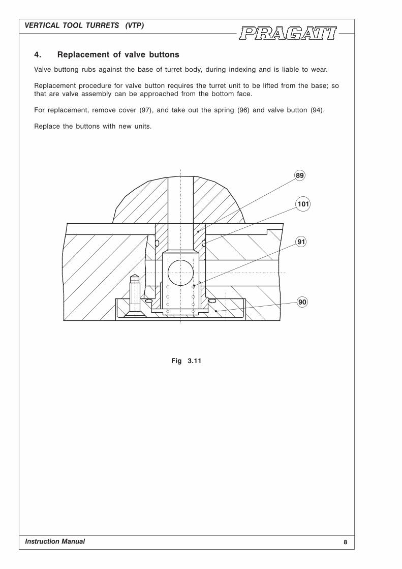
4. Replacement of valve buttons
Valve buttong rubs against the base of turret body, during indexing and is liable to wear.
Replacement procedure for valve button requires the turret unit to be lifted from the base; so
that are valve assembly can be approached from the bottom face.
For replacement, remove cover (97), and take out the spring (96) and valve button (94).
Replace the buttons with new units.
Fig 3.11
VERTICAL TOOL TURRETS (VTP)
Instruction Manual 9
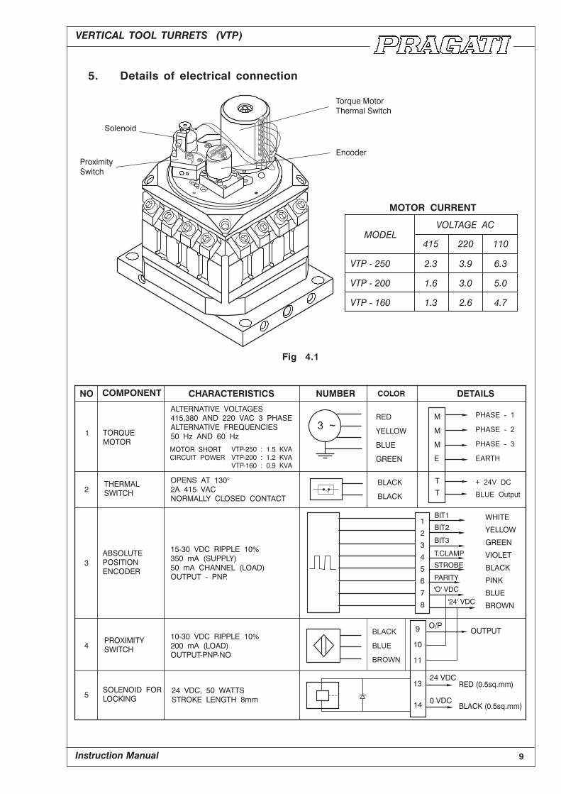
5. Details of electrical connection
Fig 4.1

10
VERTICAL TOOL TURRETS (VTP)
Instruction Manual
6. Encoder Signals
Fig 5.1
It is important to remember that encoder is connected to the internal gear (18), and
not to the turret body (1). Turret body is stationary during ‘Declamp’ and ‘Clamp’
operation, but encoder moves along with internal gear.
Indexing from position No. 2 to position No. 4 :
Sequence of operation; and encoder signals :
(1) Start position. Motor switched ON. Encoder starts rotating along with internal gear,
but turret body is stationary.
(2) Turret indexing movement starts. Encoder angular movement is now synchronised with
angular movement of turret. PLC starts looking for coincidence. (i.e., demanded
position = encoder feedback position).
(3) At some distance (40°) before the final position, encoder signals show that the desired
position is approaching. That is to stay encoder feedback indicates coincidence.
(demanded position = actual position). At this point, PLC should energize the solenoid.
(4) Desired physical position of turret reached. Solenoid plunger slides down into its slot
to arrest the turret movement. Drive motor stalls. Solenoid proximity switch becomes
ON. Motor is switched OFF.
(5) With the shortest possible delay, motor is switched ON in reverse direction. Turret
remains stationary. Encoder rotates along with internal gear.
(6) After 40° of reverse rotation, turret is clamped in its new position, Encoder ‘clamp’
signal becomes ON. Motor is switched OFf and Solenoid is switched OFF. Cycle
complete.
VERTICAL TOOL TURRETS (VTP)
Instruction Manual 11
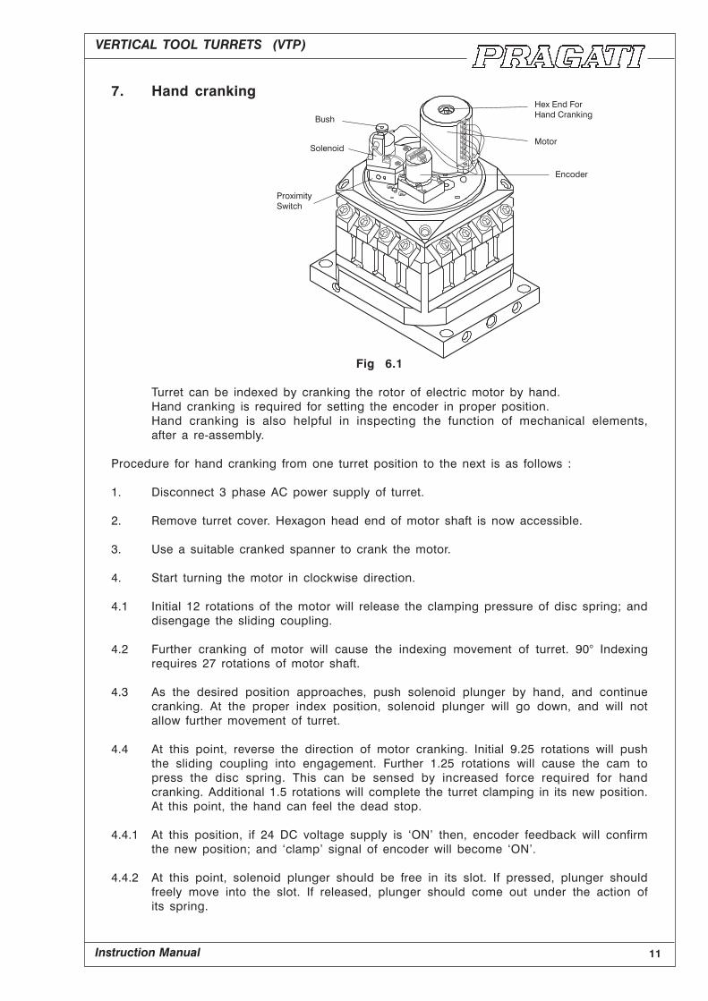
7. Hand cranking
Fig 6.1
Turret can be indexed by cranking the rotor of electric motor by hand.
Hand cranking is required for setting the encoder in proper position.
Hand cranking is also helpful in inspecting the function of mechanical elements,
after a re-assembly.
Procedure for hand cranking from one turret position to the next is as follows :
1. Disconnect 3 phase AC power supply of turret.
2. Remove turret cover. Hexagon head end of motor shaft is now accessible.
3. Use a suitable cranked spanner to crank the motor.
4. Start turning the motor in clockwise direction.
4.1 Initial 12 rotations of the motor will release the clamping pressure of disc spring; and
disengage the sliding coupling.
4.2 Further cranking of motor will cause the indexing movement of turret. 90° Indexing
requires 27 rotations of motor shaft.
4.3 As the desired position approaches, push solenoid plunger by hand, and continue
cranking. At the proper index position, solenoid plunger will go down, and will not
allow further movement of turret.
4.4 At this point, reverse the direction of motor cranking. Initial 9.25 rotations will push
the sliding coupling into engagement. Further 1.25 rotations will cause the cam to
press the disc spring. This can be sensed by increased force required for hand
cranking. Additional 1.5 rotations will complete the turret clamping in its new position.
At this point, the hand can feel the dead stop.
4.4.1 At this position, if 24 DC voltage supply is ‘ON’ then, encoder feedback will confirm
the new position; and ‘clamp’ signal of encoder will become ‘ON’.
4.4.2 At this point, solenoid plunger should be free in its slot. If pressed, plunger should
freely move into the slot. If released, plunger should come out under the action of
its spring.

12
VERTICAL TOOL TURRETS (VTP)
Instruction Manual
8. Flowchart for turret control
VERTICAL TOOL TURRETS (VTP)
Instruction Manual 13
9. Requirements of turret control
Flow chart for turret control is given on page 11. Any modern PLC with scan
time of 8 to 10 milliseconds) will be capable of handling the sequence as specified
in flow chart.
9.1 Safety Features :
9.11 ‘Motor Overheat Signal’
Turret motor has been designed with a special winding, to allow a large number of
‘starts, stops and reversals, per minute. However, the motor can get overheated.
If it is allowed to run continuously for a long time, even on no load. As a saftey
measure, a thermal switch embedded in motor windings. In the event of over
heating, thermal switch should trip the motor contactor; and also give ‘motor’
overheaf signal to the control circuit. Motor contactor should be tripped, without
depending on PLC software.
9.12 ‘Time Fault’ Alarm
Time required for indexing varies from 1.5 to 5 seconds depending on number of
indexes. So 5 seconds is the maximum time required for completing any indexing
operation. If the ‘Cycle Complete’ signal is not received within 10 seconds after the
‘Cycle start’, then ‘Time Fault’ alarm should be generated.
9.13 ‘Turret Not Locked’ Alarm
Turret clamp switch should be monitored at the end of indexing cycle. If the clamp
signals missing, ‘a feed hold’ signal should be generated to stop the machine
movements. Simultaneously, ‘Turret Not Locked’ alarm signal should be generated.
9.14 ‘Position Fault’ Alarm
At the end of indexing cycle, a check should be made to ensure that the turret has
indexed to the demanded position. If the actual position and demanded position
do not match, then ‘Position Fault’ alarm signal should be generated.
9.15 ‘Invalid Demand’ Alarm
A 4 position turret cannot react to a tool demand other than 1 to 4. If any other tool
position (Say 6) is demanded; control should give out ‘Invalid Demand’ alarm.
All these alarms should stop the operation of the machine and an indication should
be available on the control panel regarding the nature the fault.
14
VERTICAL TOOL TURRETS (VTP)
Instruction Manual
9.2 ‘Manual Mode’ of turret control
Control panel should have a facility to change over the turret control to manual
mode. Following facilities should be available in this mode.
9.21 ‘Inching’ the motor is either direction :
During servicing, it is sometimes necessary to rotate the motor for checking the
functioning of the turret mechanism. Push button switches should be provided to
allow ‘Inching’ of the motor in either direction.
9.22 Tool indexing cycle on manual demand :
If the power falls during the indexing cycle, turret can stop in an unclamped position.
It is then possible that valid encoder feedback is not available because the turret
has stopped in an intermediate position. In such a case, control should provides
a facility to index the turret into desired position by manual data entry of ‘tool demand’
This can be either by a ‘thumb wheel’ switch, or by push button data entry through
CNC panel.
Indexing cycle through manual tool demand will be identical to the normal indexing
cycle, except for the fact the cycle will start even if initial signal conditions are not
satisfied.
10. Lubrication
Vertical Turrets are lubricated for life, using Kluber Isoflex Grease.
If the turret is opened for servicing, all internal components should be thorougly
cleaned; and relubricated with grease; before re-assembly.
Following grease is recommended;
Kluber Isoflex NBU 15.

VERTICAL TOOL TURRETS (VTP)
Instruction Manual 15
11. Adjustment of rotary encoder
Fig 10.1
1. Hand crank the turret, and clamp it in position No. 1 (Refer ‘hand cranking’ page 10).
Clamped position of the turret is sensed by Increased load on the hand lever,
ultimately reaching a dead stop.
2. Check that the line mark on the face of gear is in line with the line mark on encoder
shaft; as shown in the figure.
3. Align the orientation line mark on gear to white orientation mark on the body of encoder.
4. Hold the encoder assembly just above its sealing position, and align the orientation
mark on encoder with orientation mark on the mounting block.
5. Carefully insert the encoder into its sealing position, so that encoder gear (12) meshes
with pinion (11). Align the encoder mark, and clamp the encoder loosely in position.
6. Supply 24 VDC power to the encoder and observe the encoder outputs. Slowly rotate
encoder in its position, and observe the ‘clamp’ signal. Clamp the encoder, so that
it is rougly in the middle of clamp signal. At this point, encoder signals should indicate
position No. 1; and clamp signal should be ‘ON’.
7. Hand crank the turret in clockwise direction of next indexing ‘Clamp’ signal of encoder
should remain ‘ON’ for at least one full revolution of motor shaft.
Hand crank the turret, and clamp it in position No. 2. Observe the encoder signals
and confirm that they are as per expectation.
Fig 10.2
16
VERTICAL TOOL TURRETS (VTP)
Instruction Manual
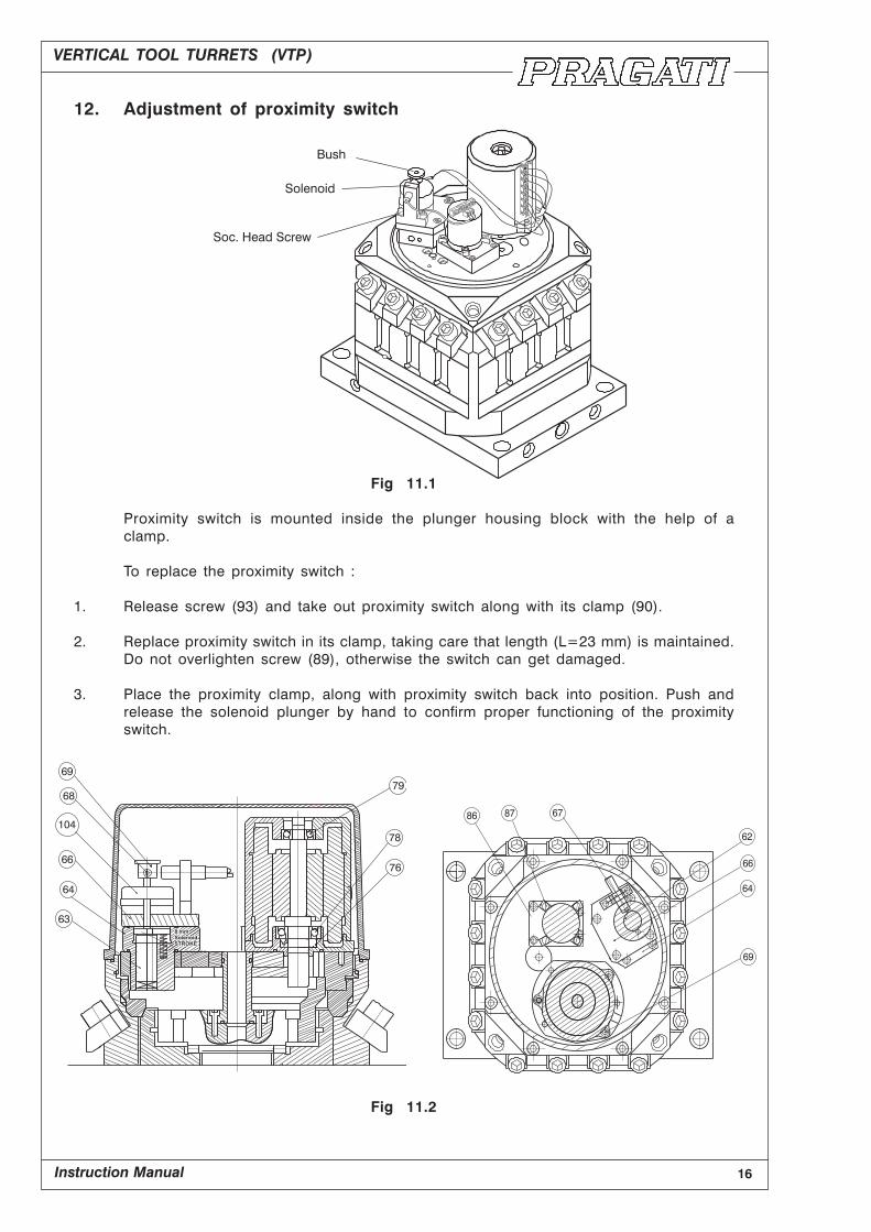
12. Adjustment of proximity switch
Fig 11.1
Proximity switch is mounted inside the plunger housing block with the help of a
clamp.
To replace the proximity switch :
1. Release screw (93) and take out proximity switch along with its clamp (90).
2. Replace proximity switch in its clamp, taking care that length (L=23 mm) is maintained.
Do not overlighten screw (89), otherwise the switch can get damaged.
3. Place the proximity clamp, along with proximity switch back into position. Push and
release the solenoid plunger by hand to confirm proper functioning of the proximity
switch.
Fig 11.2
VERTICAL TOOL TURRETS (VTP)
Instruction Manual 17
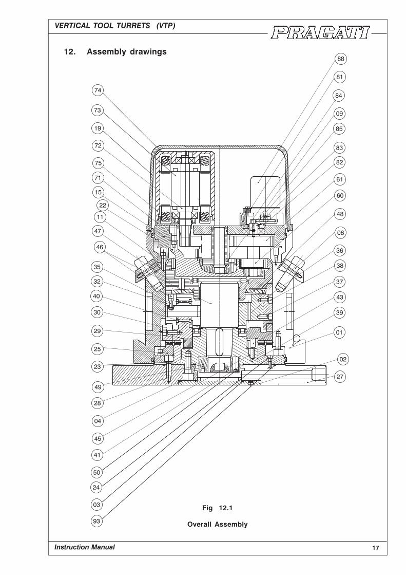
12. Assembly drawings
Fig 12.1
Overall Assembly

18
VERTICAL TOOL TURRETS (VTP)
Instruction Manual
Fig 12.2
Spindle Assembly
VERTICAL TOOL TURRETS (VTP)
Instruction Manual 19
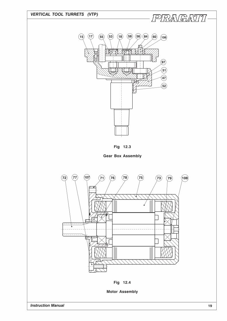
Fig 12.3
Gear Box Assembly
Fig 12.4
Motor Assembly
20
VERTICAL TOOL TURRETS (VTP)
Instruction Manual
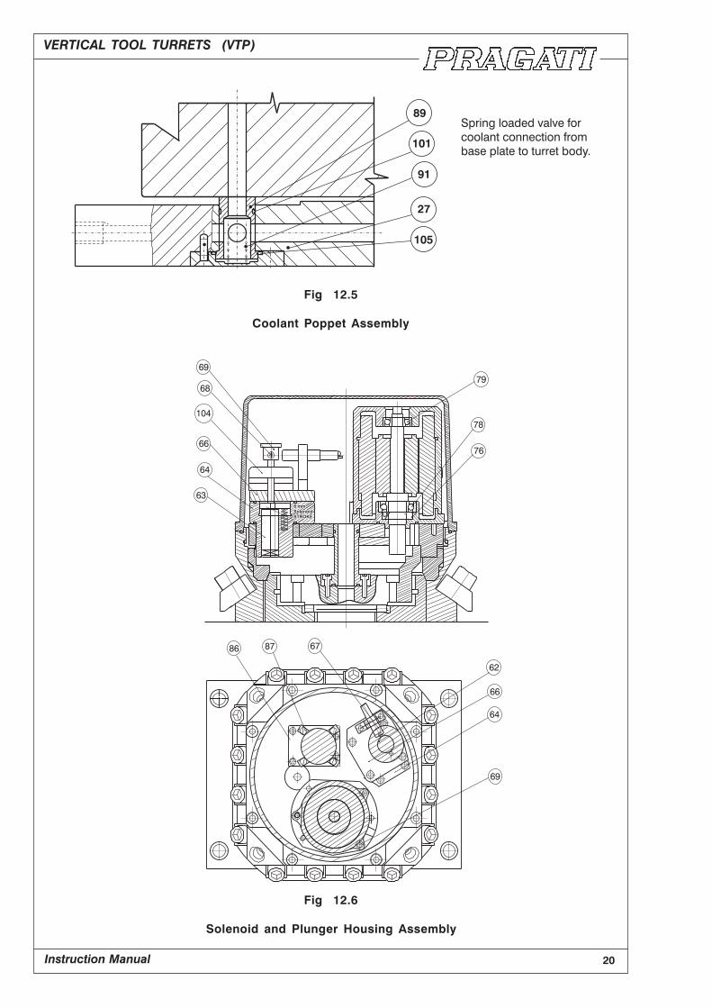
Fig 12.5
Coolant Poppet Assembly
Fig 12.6
Solenoid and Plunger Housing Assembly

VERTICAL TOOL TURRETS (VTP)
Instruction Manual 21
14 List of VTP Parts :
Sl. No. Description Make Final Size Quantity
1 Main Body Pragati Pragati 1
2 Bottom Cover Pragati Pragati 1
3 O - Ring Pragati 75 x 81.8 x 1.8 1
4 O - Ring Pragati 127 x 136.8 x 1.8 1
5 Soc. Hd. Screw High Tensile M 5 x 15 4
(GRADE)
6 Clamp Pragati Pragati 16
7 Clamp Spring Spring Steel Ø 0.5 x Ø 6 x 9.8 16
8 Clamp Bolt M 16 x 1.5 Pragati Pragati 16
9 Cable Duct Pragati Pragati 1
10 Soc. Head Screw High Tensile M 5 x 20 4
(GRADE)
11 Solenoid Ring Pragati Pragati 1
12 Cyl. Pin EN 353 Ø 8H8 x 30 2
13 Key For Solenoid Ring Pragati Pragati 2
14 Soc. Head Screw High Tensile M 6 x 20 12
(GRADE)
15 Top Plate Pragati Pragati 1
16 Cyl. Pin 6H 8 x 42 Pragati Ø 6H8 x 42 1
17 Soc. Head Screw High Tensile M 8 x 30 8/7
(GRADE)
18 Bearing Cover Pragati Pragati 2
19 Top Dome Pragati Pragati 1
20 Soc. Head Screw High Tensile M 5 x 15 4
(GRADE)
21 Turcon Seal Pragati 220 x 228.8 x 6 1
22 Turcon Seal VAKO 220 x 228.8 x 6 1
23 Fixed Coupling Pragati Pragati 1
24 Cyl. Pin EN 353 Ø 6H 8 x 20 2

22
VERTICAL TOOL TURRETS (VTP)
Instruction Manual
Sl. No. Description Make Final Size Quantity
25 Rotating Coupling Pragati Pragati 1
26 Cyl. Pin EN 353 ¢ 8H 8 x 20 2
27 Base Plate Pragati Pragati 1
28 Soc. Head Screw High Tensile M 8 x 25 14
(GRADE)
29 Sliding Coupling Pragati Pragati 1
30 Drive Key Short Pragati Pragati 1
31 Soc. Head Screw High Tensile M 8 x 20 1
(GRADE)
32 Roller Housing Pragati Pragati 1
33 Roller Ping Pragati Pragati 3
34 Roller Steel Pragati 3
35 Soc. Head Screw High Tensile M5 x 16 3
(GRADE)
36 Drive Key Long Pragati Pragati 1
37 Soc. Head Screw High Tensile M 6 x 16 1
(GRADE)
38 Soc. Head Screw High Tensile M 6 x 14 1
(GRADE)
39 Main Flange Pragati Pragati 1
40 O - Ring VAKO ¢ 57 x 2 1
41 O - Ring UNBRAKO ¢ 80 x 3 1
42 AXi Cylinder RB Steel ¢ 65 x ¢ 90 x 18 1
43 Spring Seat Pragati Pragati 1
44 Spring Spring Steel W1.4x0D11.5x53.6 4
45 Special Screw - M6x15 Pragati Pragati 4
46 Main Shaft Pragati Pragati 1
47 Internal Gear Pragati Pragati 1
48 Disc Spring INA ¢ 87 x ¢ 160 x 8 1
49 Lock Nut Pragati Pragati 1

VERTICAL TOOL TURRETS (VTP)
Instruction Manual 23
Sl. No. Description Make Final Size Quantity
50 Soc. Head Grub Screw High Tension M 10 x 25 4
Steel
51 Axial Thrust Bearing Steel Ø 70 x Ø 95 x 18 1
52 Needle Cage Bearing Steel Ø 65 x Ø 70 x 20 1
53 Gear Shaft II Pragati Pragati 1
54 Gear 2 Pragati Pragati 1
55 Deep Groove BB Steel Ø 15 x Ø 35 x 11 5
56 External Circlip C.I. Grade Ø 23.2 x 1 4
57 Key STD. 20 x 6 x 5 3
58 Gear Shaft III Pragati Pragati 1
59 Gear III Pragati Pragati 1
60 Gear Shaft IV Pragati Pragati 1
61 Gear 4 Pragati Pragati 1
62 Solenoid Assy. - - - - 1
63 Plunger Pragati Pragati 1
64 Plunger Housing Pragati Pragati 1
65 Helical Spring Spring Steel OD 6 x W 0.7 x 30 2
66 Solenoid Mtg. Plate Pragati Pragati 1
67 Proximity Clamp Pragati Pragati 1
68 Bush Pragati Pragati 1
69 Soc. Head Screw High Tension M 4 x 5 1
Steel
70 Motor Asssy.1440 Rpm - - - - 1
71 Motor Mtg. Flange Pragati Pragati 1
72 Motor Shaft Pragati Pragati 1
73 Rotor Pragati Pragati 1
74 Stator Pragati Pragati 1
75 Motor Housing Pragati Pragati 1
76 Turcon Seal Pragati Ø 20 x Ø 35 x 7 1
77 Soc. Head Screw Spring Steel M 6 x 25 3
78 Ang. Cont. BB Steel Ø 20 x Ø 42 x 12 1
24
VERTICAL TOOL TURRETS (VTP)
Instruction Manual
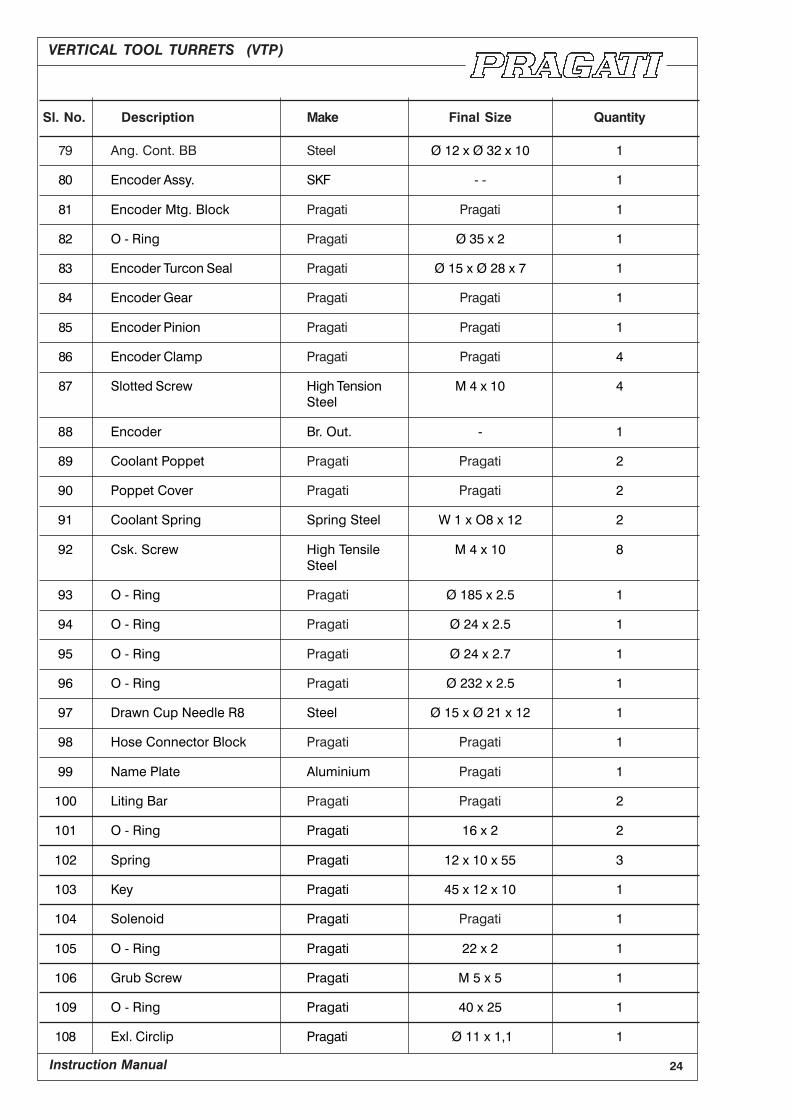
Sl. No. Description Make Final Size Quantity
79 Ang. Cont. BB Steel Ø 12 x Ø 32 x 10 1
80 Encoder Assy. SKF - - 1
81 Encoder Mtg. Block Pragati Pragati 1
82 O - Ring Pragati Ø 35 x 2 1
83 Encoder Turcon Seal Pragati Ø 15 x Ø 28 x 7 1
84 Encoder Gear Pragati Pragati 1
85 Encoder Pinion Pragati Pragati 1
86 Encoder Clamp Pragati Pragati 4
87 Slotted Screw High Tension M 4 x 10 4
Steel
88 Encoder Br. Out. - 1
89 Coolant Poppet Pragati Pragati 2
90 Poppet Cover Pragati Pragati 2
91 Coolant Spring Spring Steel W 1 x O8 x 12 2
92 Csk. Screw High Tensile M 4 x 10 8
Steel
93 O - Ring Pragati Ø 185 x 2.5 1
94 O - Ring Pragati Ø 24 x 2.5 1
95 O - Ring Pragati Ø 24 x 2.7 1
96 O - Ring Pragati Ø 232 x 2.5 1
97 Drawn Cup Needle R8 Steel Ø 15 x Ø 21 x 12 1
98 Hose Connector Block Pragati Pragati 1
99 Name Plate Aluminium Pragati 1
100 Liting Bar Pragati Pragati 2
101 O - Ring Pragati 16 x 2 2
102 Spring Pragati 12 x 10 x 55 3
103 Key Pragati 45 x 12 x 10 1
104 Solenoid Pragati Pragati 1
105 O - Ring Pragati 22 x 2 1
106 Grub Screw Pragati M 5 x 5 1
109 O - Ring Pragati 40 x 25 1
108 Exl. Circlip Pragati Ø 11 x 1,1 1
VERTICAL TOOL TURRETS (VTP)
Instruction Manual 25
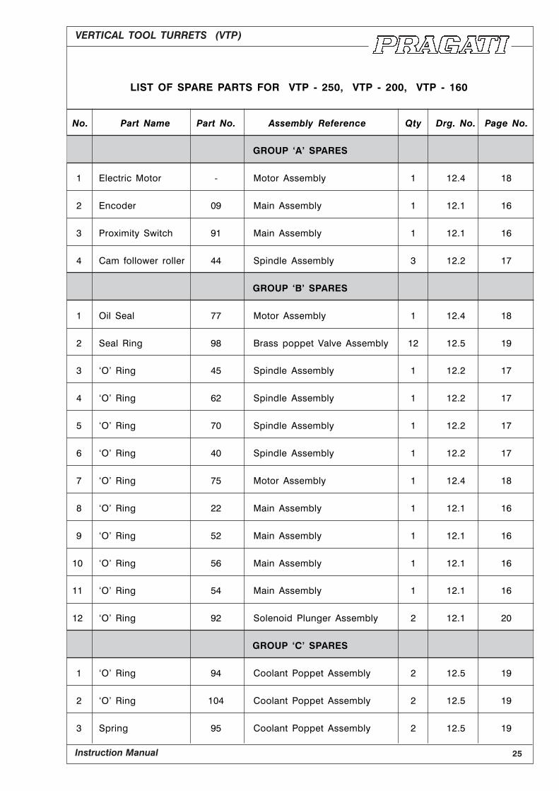
LIST OF SPARE PARTS FOR VTP - 250, VTP - 200, VTP - 160
No. Part Name Part No. Assembly Reference Qty Drg. No. Page No.
GROUP ‘A’ SPARES
1 Electric Motor - Motor Assembly 1 12.4 18
2 Encoder 09 Main Assembly 1 12.1 16
3 Proximity Switch 91 Main Assembly 1 12.1 16
4 Cam follower roller 44 Spindle Assembly 3 12.2 17
GROUP ‘B’ SPARES
1 Oil Seal 77 Motor Assembly 1 12.4 18
2 Seal Ring 98 Brass poppet Valve Assembly 12 12.5 19
3 ‘O’ Ring 45 Spindle Assembly 1 12.2 17
4 ‘O’ Ring 62 Spindle Assembly 1 12.2 17
5 ‘O’ Ring 70 Spindle Assembly 1 12.2 17
6 ‘O’ Ring 40 Spindle Assembly 1 12.2 17
7 ‘O’ Ring 75 Motor Assembly 1 12.4 18
8 ‘O’ Ring 22 Main Assembly 1 12.1 16
9 ‘O’ Ring 52 Main Assembly 1 12.1 16
10 ‘O’ Ring 56 Main Assembly 1 12.1 16
11 ‘O’ Ring 54 Main Assembly 1 12.1 16
12 ‘O’ Ring 92 Solenoid Plunger Assembly 2 12.1 20
GROUP ‘C’ SPARES
1 ‘O’ Ring 94 Coolant Poppet Assembly 2 12.5 19
2 ‘O’ Ring 104 Coolant Poppet Assembly 2 12.5 19
3 Spring 95 Coolant Poppet Assembly 2 12.5 19