Embed Size (px)
Citation preview
2
Vertebral Column: OverviewBa
ck
Fig. 1.1 Vertebral column Left lateral view.
The vertebral column (spine) is divided into four regions: the cervical, thoracic, lumbar, and sacral spines. Both the cervical
and lumbar spines demonstrate lordosis (inward curvature); the thoracic and sacral spines demonstrate kyphosis (outward curvature).
A Regions of the spine.
B Bony vertebral column.
Clinical
Spinal developmentThe characteristic curvatures of the adult spine appear over the course of postnatal development, being only partially present in a newborn. The newborn has a “kyphotic” spinal curvature (A); lumbar lordosis develops later and becomes stable at puberty (C).
A B C
3
1 Bones, Ligaments &
Joints
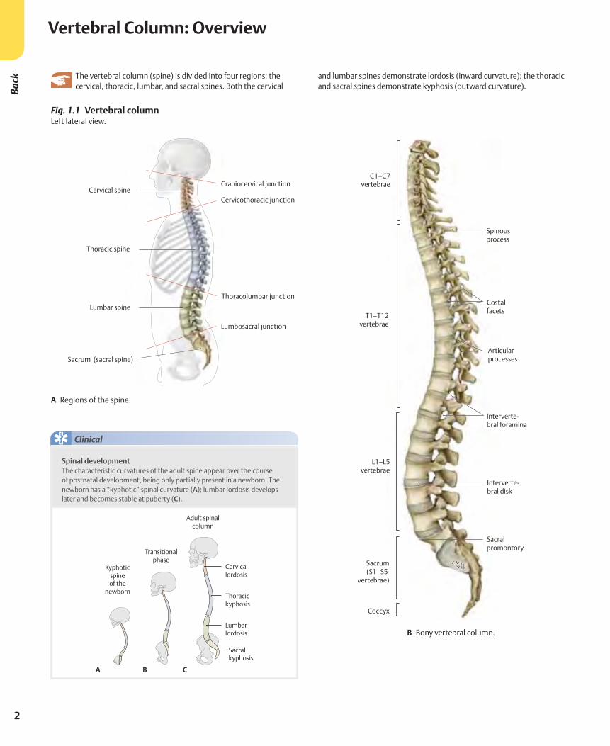
B Midsagittal section through an adult male.
Fig. 1.2 Normal anatomical position of the spine Left lateral view.
A Line of gravity. The line of gravity passes through certain anatomical landmarks, including the inflection points at the cervi-cothoracic and thoracolumbar junctions. It continues through the center of gravity (anterior to the sacral promontory) before passing through the hip joint, knee, and ankle.
4
Vertebral Column: ElementsBa
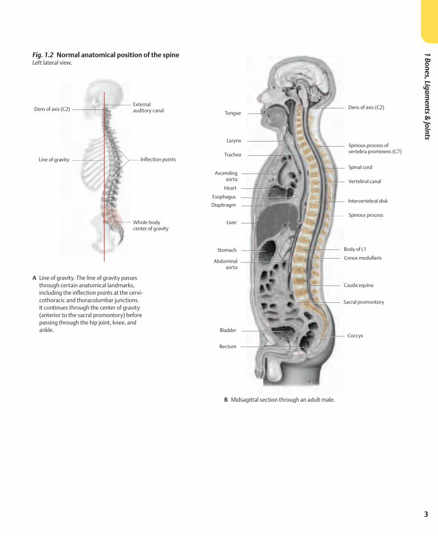
ck Fig. 1.3 Bones of the vertebral column
A Anterior view. B Posterior view.
Fig. 1.4 Palpable spinous processes as landmarks Posterior view. The easily palpated spinous processes provide important landmarks dur-ing physical examination.
5
1 Bones, Ligaments &
Joints
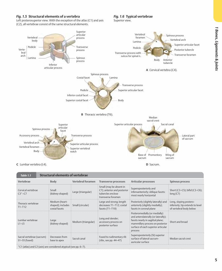
Fig. 1.5 Structural elements of a vertebra Left posterosuperior view. With the exception of the atlas (C1) and axis (C2), all vertebrae consist of the same structural elements.
Fig. 1.6 Typical vertebraeSuperior view.
A Cervical vertebra (C4).
B Thoracic vertebra (T6).
C Lumbar vertebra (L4). D Sacrum.
Table 1.1 Structural elements of vertebrae
Vertebrae Body Vertebral foramen Transverse processes Articular processes Spinous process
Cervical vertebraeC3*–C7
Small (kidney-shaped)
Large (triangular)
Small (may be absent in C7); anterior and posterior tubercles enclose transverse foramen
Superoposteriorly and inferoanteriorly; oblique facets: most nearly horizontal
Short (C3–C5); bifid (C3–C6); long (C7)
Thoracic vertebraeT1–T12
Medium (heart-shaped); includes costal facets
Small (circular)Large and strong; length decreases T1–T12; costal facets (T1–T10)
Posteriorly (slightly laterally) and anteriorly (slightly medially); facets in coronal plane
Long, sloping postero-inferiorly; tip extends to level of vertebral body below
Lumbar vertebraeL1–L5
Large (kidney-shaped)
Medium (triangular)Long and slender; accessory process on posterior surface
Posteromedially (or medially) and anterolaterally (or laterally); facets nearly in sagittal plane; mammillary process on posterior surface of each superior articular process
Short and broad
Sacral vertebrae (sacrum)S1–S5 (fused)
Decreases from base to apex
Sacral canalFused to rudimentary rib (ribs, see pp. 44–47)
Superoposteriorly (SI) superior surface of lateral sacrum-auricular surface
Median sacral crest
*C1 (atlas) and C2 (axis) are considered atypical (see pp. 6–7).
6
Cervical VertebraeBa
ck
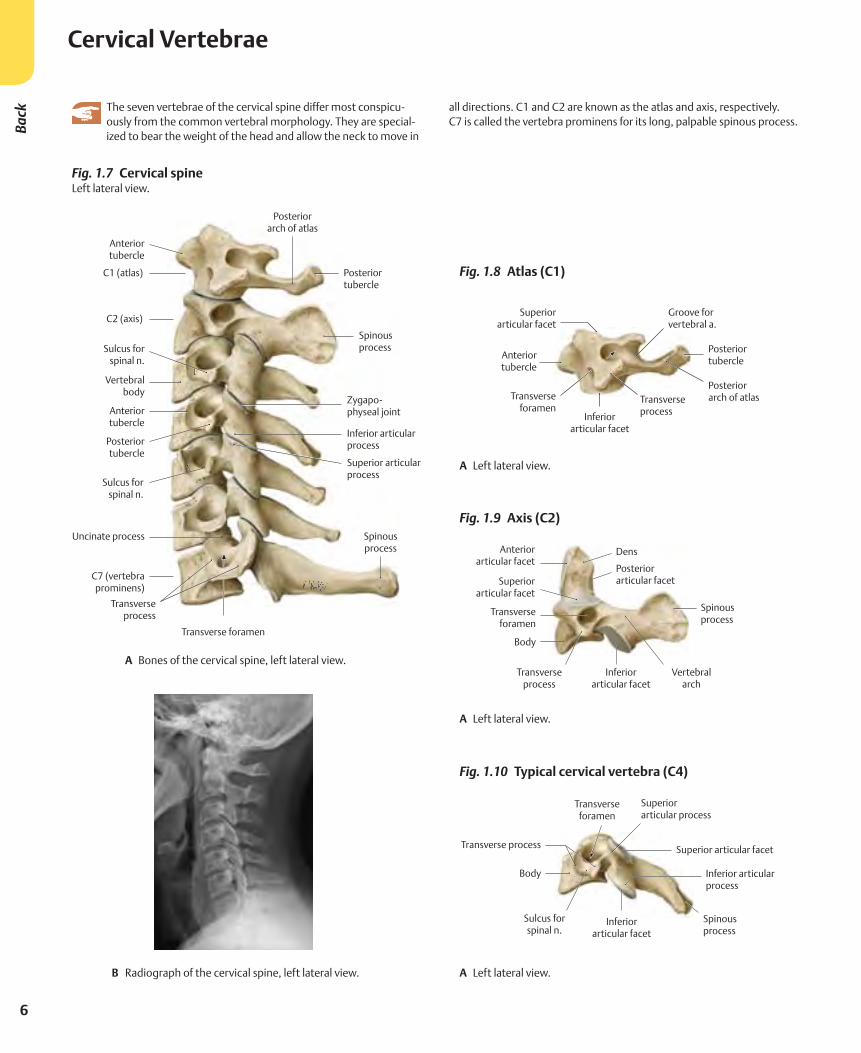
Fig. 1.7 Cervical spine Left lateral view.
A Bones of the cervical spine, left lateral view.
B Radiograph of the cervical spine, left lateral view.
Fig. 1.8 Atlas (C1)
Fig. 1.9 Axis (C2)
Fig. 1.10 Typical cervical vertebra (C4)
A Left lateral view.
A Left lateral view.
A Left lateral view.
The seven vertebrae of the cervical spine differ most conspicu-ously from the common vertebral morphology. They are special-ized to bear the weight of the head and allow the neck to move in
all directions. C1 and C2 are known as the atlas and axis, respectively. C7 is called the vertebra prominens for its long, palpable spinous process.
7
1 Bones, Ligaments &
Joints
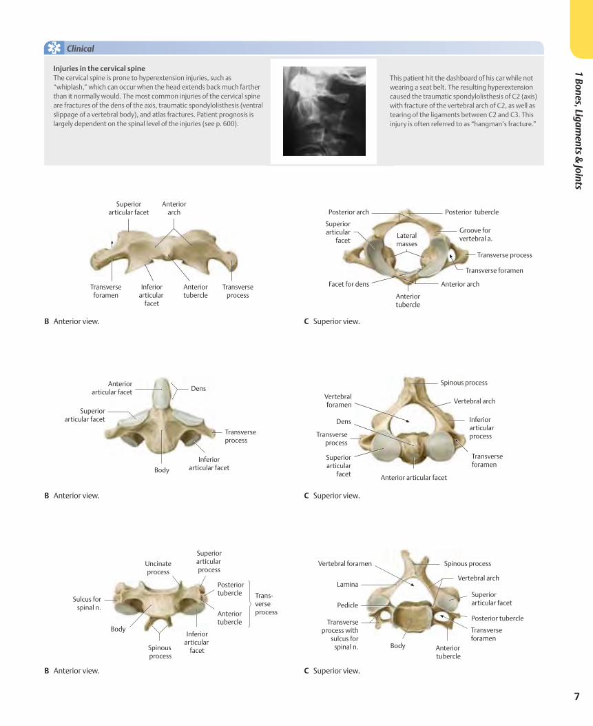
B Anterior view. C Superior view.
B Anterior view. C Superior view.
B Anterior view. C Superior view.
Clinical
Injuries in the cervical spine The cervical spine is prone to hyperextension injuries, such as “whiplash,” which can occur when the head extends back much farther than it normally would. The most common injuries of the cervical spine are fractures of the dens of the axis, traumatic spondylolisthesis (ventral slippage of a vertebral body), and atlas fractures. Patient prognosis is largely dependent on the spinal level of the injuries (see p. 600).
This patient hit the dashboard of his car while not wearing a seat belt. The resulting hyperextension caused the traumatic spondylolisthesis of C2 (axis) with fracture of the vertebral arch of C2, as well as tearing of the ligaments between C2 and C3. This injury is often referred to as “hangman’s fracture.”
8
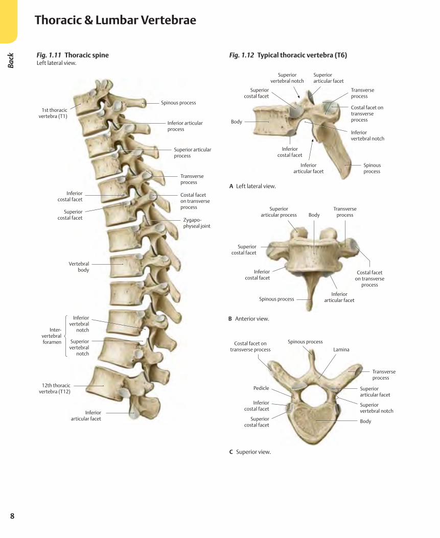
Fig. 1.11 Thoracic spine Left lateral view.
Fig. 1.12 Typical thoracic vertebra (T6)
A Left lateral view.
B Anterior view.
C Superior view.
Thoracic & Lumbar VertebraeBa
ck
9
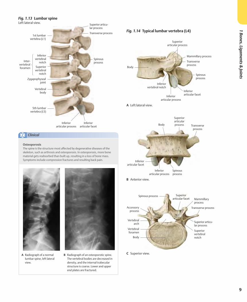
Fig. 1.13 Lumbar spine Left lateral view.
Fig. 1.14 Typical lumbar vertebra (L4)
A Left lateral view.
B Anterior view.
C Superior view.
Clinical
OsteoporosisThe spine is the structure most affected by degenerative diseases of the skeleton, such as arthrosis and osteoporosis. In osteoporosis, more bone material gets reabsorbed than built up, resulting in a loss of bone mass. Symptoms include compression fractures and resulting back pain.
A Radiograph of a normal lumbar spine, left lateral view.
B Radiograph of an osteoporotic spine. The vertebral bodies are decreased in density, and the internal trabecular structure is coarse. Lower and upper end plates are fractured.
1 Bones, Ligaments &
Joints
10
Back
Sacrum & Coccyx
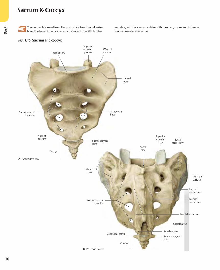
Fig. 1.15 Sacrum and coccyx
A Anterior view.
B Posterior view.
The sacrum is formed from five postnatally fused sacral verte-brae. The base of the sacrum articulates with the fifth lumbar
vertebra, and the apex articulates with the coccyx, a series of three or four rudimentary vertebrae.
11
1 Bones, Ligaments &
Joints
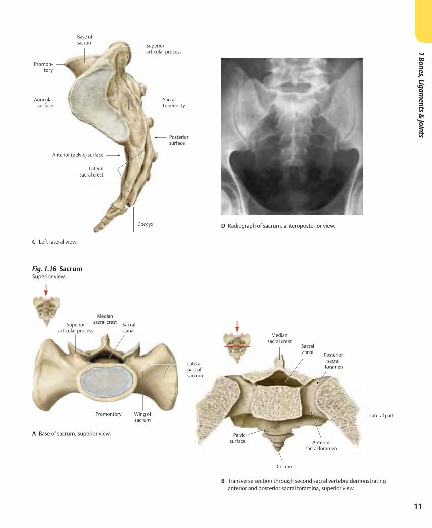
Fig. 1.16 Sacrum Superior view.
B Transverse section through second sacral vertebra demonstrating anterior and posterior sacral foramina, superior view.
A Base of sacrum, superior view.
C Left lateral view.
D Radiograph of sacrum, anteroposterior view.
12
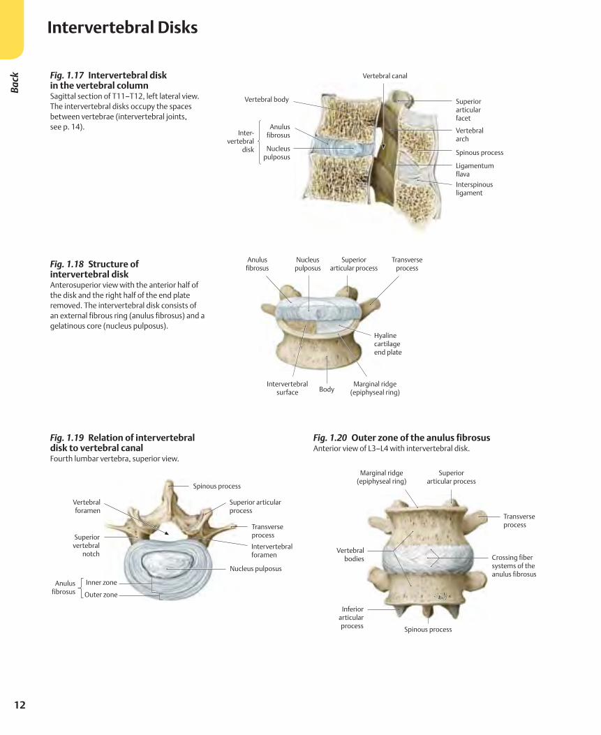
Fig. 1.20 Outer zone of the anulus fibrosus Anterior view of L3–L4 with intervertebral disk.
Intervertebral DisksBa
ck
Fig. 1.18 Structure of intervertebral diskAnterosuperior view with the anterior half of the disk and the right half of the end plate removed. The intervertebral disk consists of an external fibrous ring (anulus fibrosus) and a gelatinous core (nucleus pulposus).
Fig. 1.19 Relation of intervertebral disk to vertebral canalFourth lumbar vertebra, superior view.
Fig. 1.17 Intervertebral disk in the vertebral columnSagittal section of T11–T12, left lateral view. The intervertebral disks occupy the spaces between vertebrae (intervertebral joints, see p. 14).
13
1 Bones, Ligaments &
Joints
A Superior view. B Midsagittal T2-weighted MRI (magnetic resonance image).
C Superior view. D Posterior view, vertebral arches removed.
Clinical
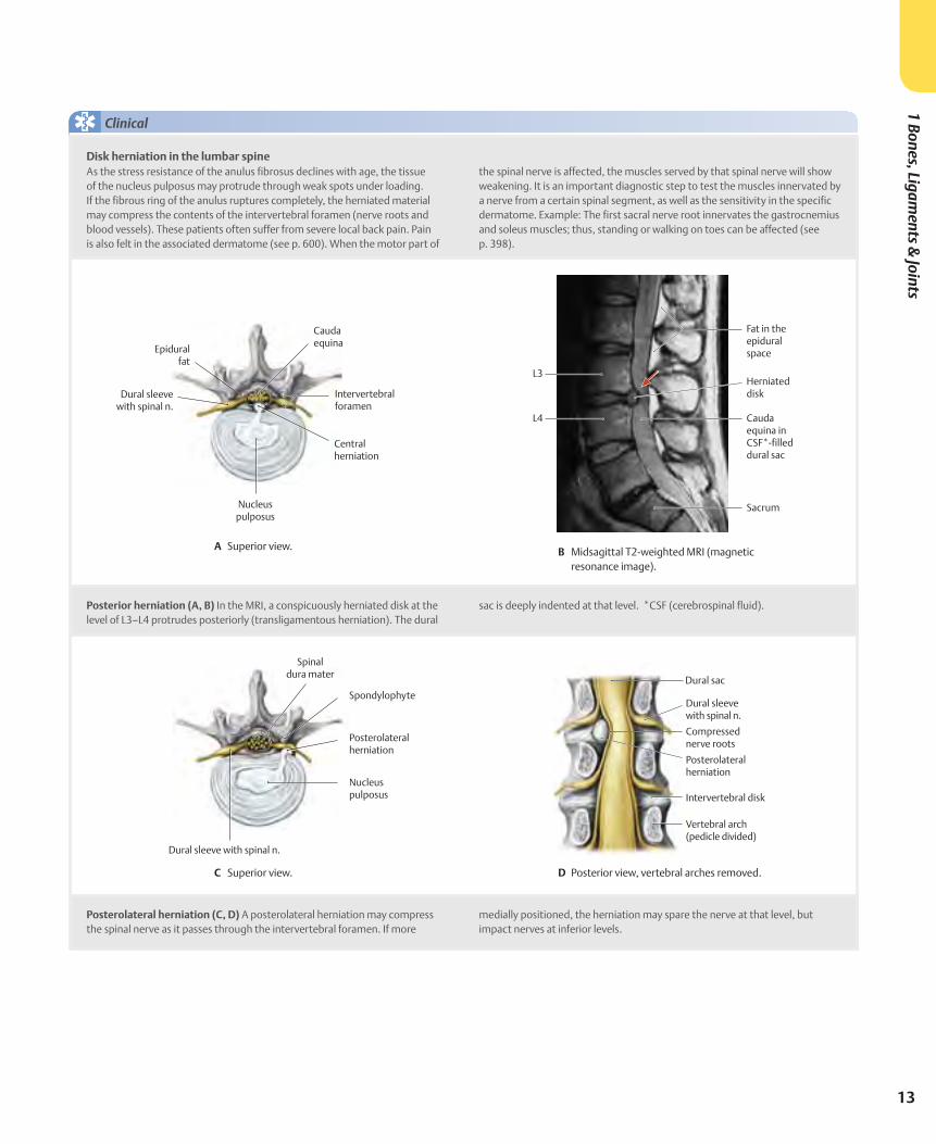
As the stress resistance of the anulus fibrosus declines with age, the tissue of the nucleus pulposus may protrude through weak spots under loading. If the fibrous ring of the anulus ruptures completely, the herniated material may compress the contents of the intervertebral foramen (nerve roots and blood vessels). These patients often suffer from severe local back pain. Pain is also felt in the associated dermatome (see p. 600). When the motor part of
the spinal nerve is affected, the muscles served by that spinal nerve will show weakening. It is an important diagnostic step to test the muscles innervated by a nerve from a certain spinal segment, as well as the sensitivity in the specific dermatome. Example: The first sacral nerve root innervates the gastrocnemius and soleus muscles; thus, standing or walking on toes can be affected (see p. 398).
Disk herniation in the lumbar spine
Posterior herniation (A, B) In the MRI, a conspicuously herniated disk at the level of L3–L4 protrudes posteriorly (transligamentous herniation). The dural
sac is deeply indented at that level. *CSF (cerebrospinal fluid).
Posterolateral herniation (C, D) A posterolateral herniation may compress the spinal nerve as it passes through the intervertebral foramen. If more
medially positioned, the herniation may spare the nerve at that level, but impact nerves at inferior levels.
14
Joints of the Vertebral Column: OverviewBa
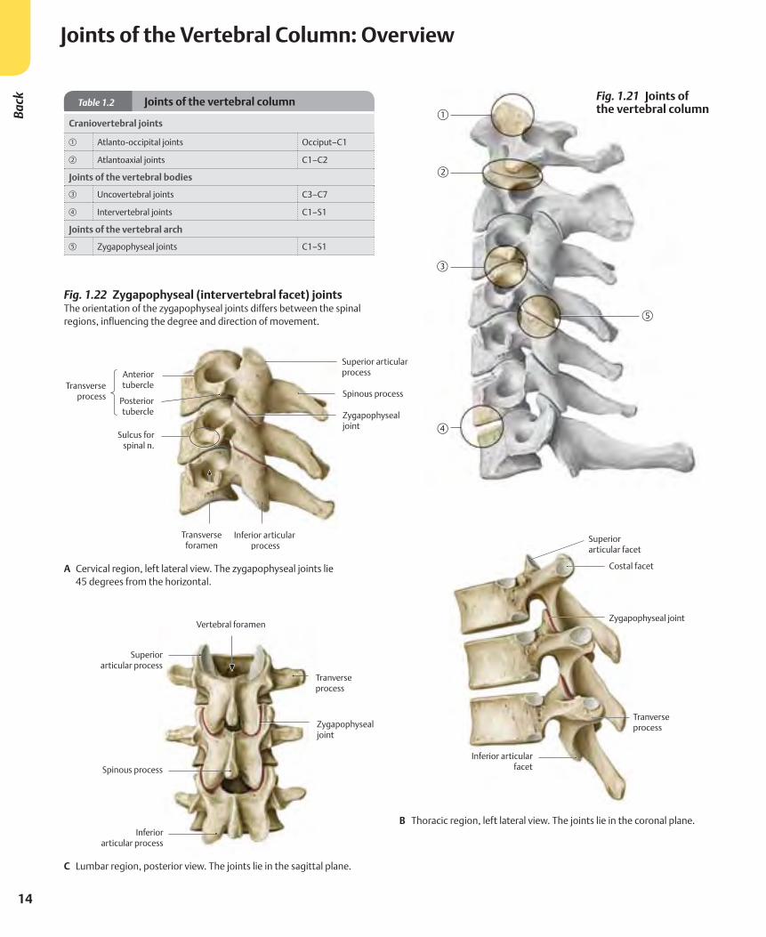
ck Table 1.2 Joints of the vertebral column
Craniovertebral joints
A Atlanto-occipital joints Occiput–C1
S Atlantoaxial joints C1–C2
Joints of the vertebral bodies
D Uncovertebral joints C3–C7
F Intervertebral joints C1–S1
Joints of the vertebral arch
G Zygapophyseal joints C1–S1
Fig. 1.21 Joints of the vertebral column
Fig. 1.22 Zygapophyseal (intervertebral facet) joints The orientation of the zygapophyseal joints differs between the spinal regions, influencing the degree and direction of movement.
A Cervical region, left lateral view. The zygapophyseal joints lie 45 degrees from the horizontal.
B Thoracic region, left lateral view. The joints lie in the coronal plane.
C Lumbar region, posterior view. The joints lie in the sagittal plane.
15
1 Bones, Ligaments &
Joints
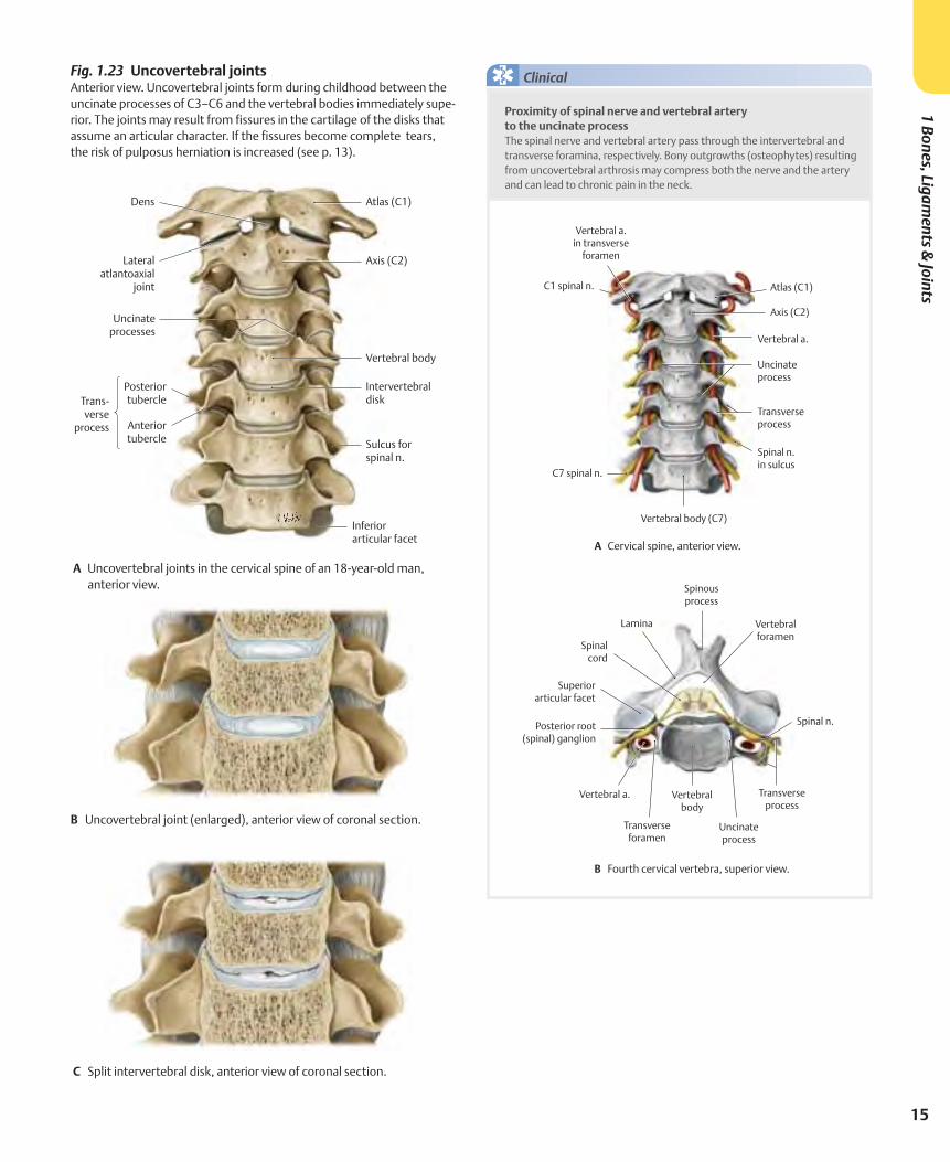
Fig. 1.23 Uncovertebral joints Anterior view. Uncovertebral joints form during childhood between the uncinate processes of C3–C6 and the vertebral bodies immediately supe-rior. The joints may result from fissures in the cartilage of the disks that assume an articular character. If the fissures become complete tears, the risk of pulposus herniation is increased (see p. 13).
A Uncovertebral joints in the cervical spine of an 18-year-old man, anterior view.
B Uncovertebral joint (enlarged), anterior view of coronal section.
C Split intervertebral disk, anterior view of coronal section.
Proximity of spinal nerve and vertebral artery to the uncinate processThe spinal nerve and vertebral artery pass through the intervertebral and transverse foramina, respectively. Bony outgrowths (osteophytes) resulting from uncovertebral arthrosis may compress both the nerve and the artery and can lead to chronic pain in the neck.
Clinical
A Cervical spine, anterior view.
B Fourth cervical vertebra, superior view.
16
Joints of the Vertebral Column: Craniovertebral RegionBa
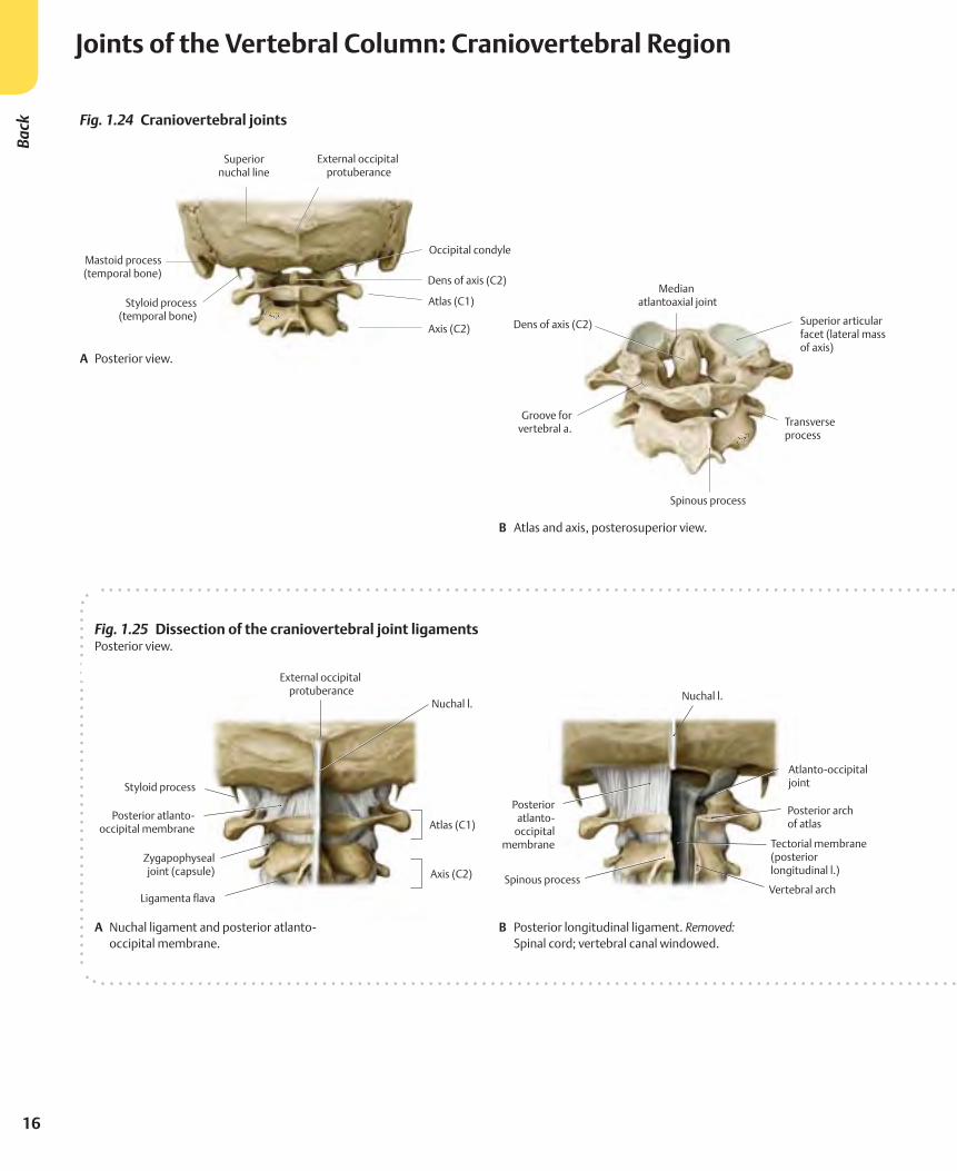
ck Fig. 1.24 Craniovertebral joints
A Posterior view.
B Atlas and axis, posterosuperior view.
Fig. 1.25 Dissection of the craniovertebral joint ligaments Posterior view.
A Nuchal ligament and posterior atlanto-occipital membrane.
B Posterior longitudinal ligament. Removed: Spinal cord; vertebral canal windowed.
17
1 Bones, Ligaments &
Joints
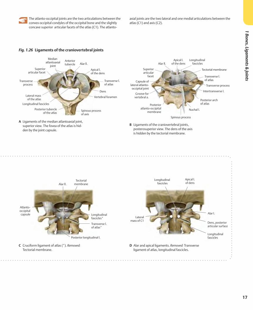
C Cruciform ligament of atlas (*). Removed: Tectorial membrane.
D Alar and apical ligaments. Removed: Transverse ligament of atlas, longitudinal fascicles.
Fig. 1.26 Ligaments of the craniovertebral joints
A Ligaments of the median atlantoaxial joint, superior view. The fovea of the atlas is hid-den by the joint capsule.
B Ligaments of the craniovertebral joints, posterosuperior view. The dens of the axis is hidden by the tectorial membrane.
The atlanto-occipital joints are the two articulations between the convex occipital condyles of the occipital bone and the slightly concave superior articular facets of the atlas (C1). The atlanto-
axial joints are the two lateral and one medial articulations between the atlas (C1) and axis (C2).
18
Vertebral Ligaments: Overview & Cervical SpineBa
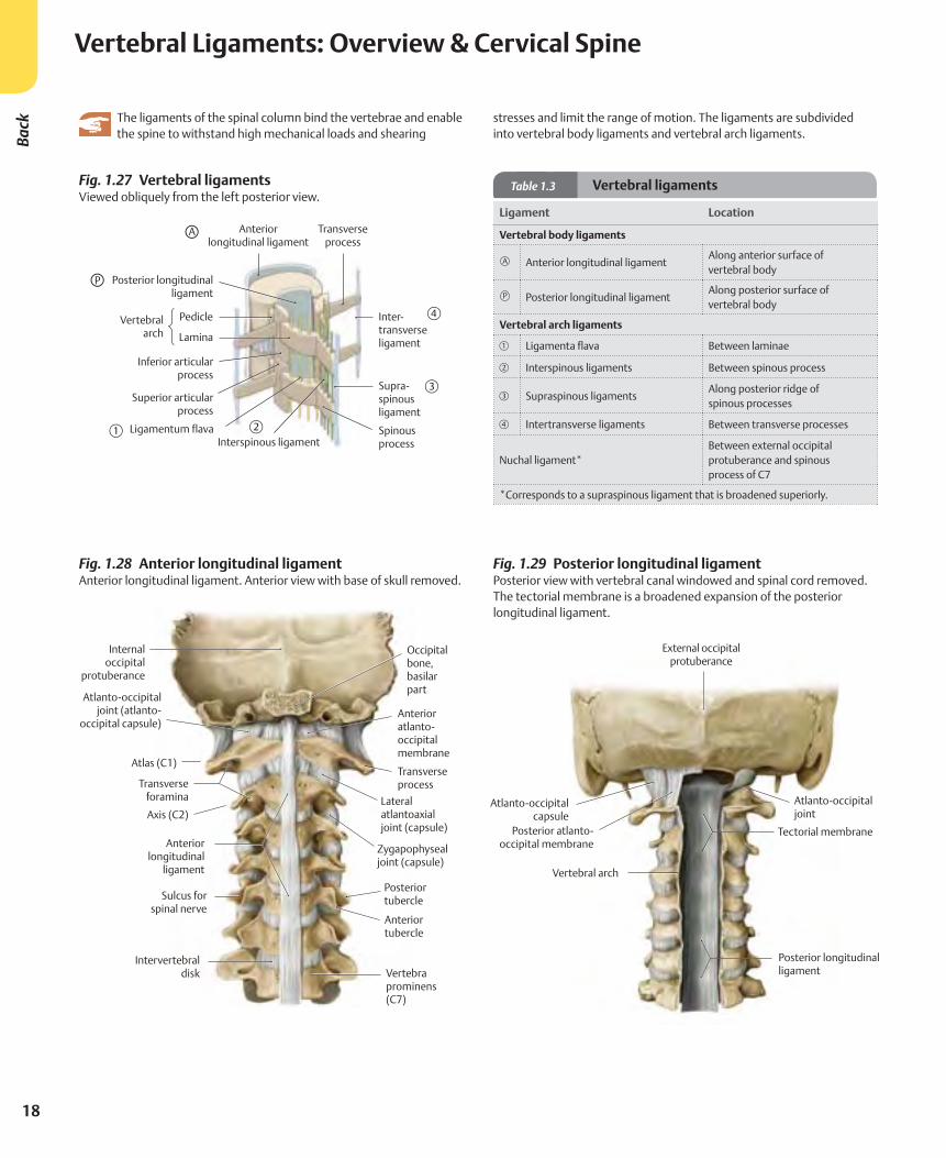
ck The ligaments of the spinal column bind the vertebrae and enable the spine to withstand high mechanical loads and shearing
stresses and limit the range of motion. The ligaments are subdivided into vertebral body ligaments and vertebral arch ligaments.
Fig. 1.27 Vertebral ligaments Viewed obliquely from the left posterior view.
Fig. 1.28 Anterior longitudinal ligamentAnterior longitudinal ligament. Anterior view with base of skull removed.
Table 1.3 Vertebral ligaments
Ligament Location
Vertebral body ligaments
Anterior longitudinal ligamentAlong anterior surface of vertebral body
Posterior longitudinal ligamentAlong posterior surface of vertebral body
Vertebral arch ligaments
A Ligamenta flava Between laminae
S Interspinous ligaments Between spinous process
D Supraspinous ligamentsAlong posterior ridge of spinous processes
F Intertransverse ligaments Between transverse processes
Nuchal ligament*Between external occipital protuberance and spinous process of C7
*Corresponds to a supraspinous ligament that is broadened superiorly.
Fig. 1.29 Posterior longitudinal ligamentPosterior view with vertebral canal windowed and spinal cord removed. The tectorial membrane is a broadened expansion of the posterior longitudinal ligament.
P
A
19
1 Bones, Ligaments &
Joints
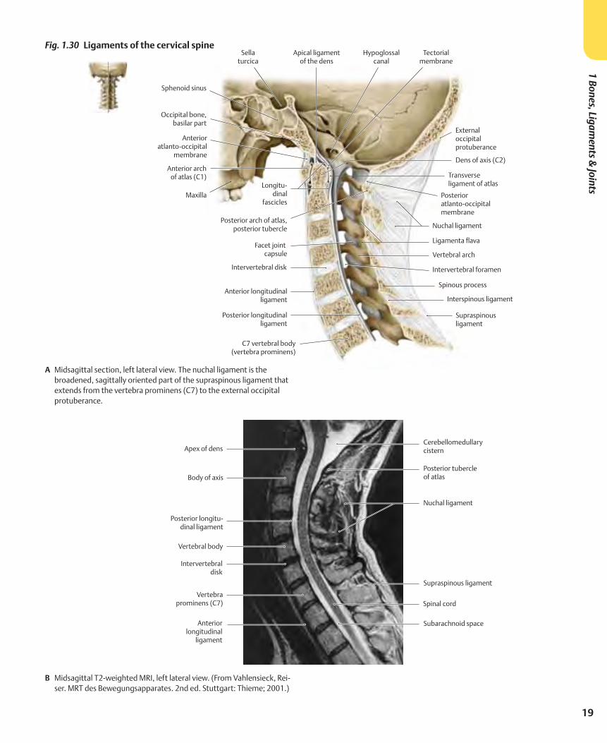
Fig. 1.30 Ligaments of the cervical spine
A Midsagittal section, left lateral view. The nuchal ligament is the broadened, sagittally oriented part of the supraspinous ligament that extends from the vertebra prominens (C7) to the external occipital protuberance.
B Midsagittal T2-weighted MRI, left lateral view. (From Vahlensieck, Rei-ser. MRT des Bewegungsapparates. 2nd ed. Stuttgart: Thieme; 2001.)
20
Back
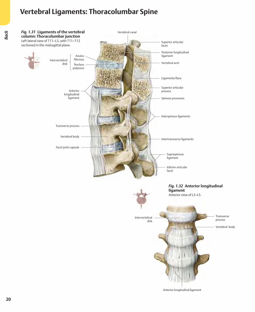
Vertebral Ligaments: Thoracolumbar Spine
Fig. 1.31 Ligaments of the vertebral column: Thoracolumbar junctionLeft lateral view of T11–L3, with T11–T12 sectioned in the midsagittal plane.
Fig. 1.32 Anterior longitudinal ligament Anterior view of L3–L5.
21
1 Bones, Ligaments &
Joints
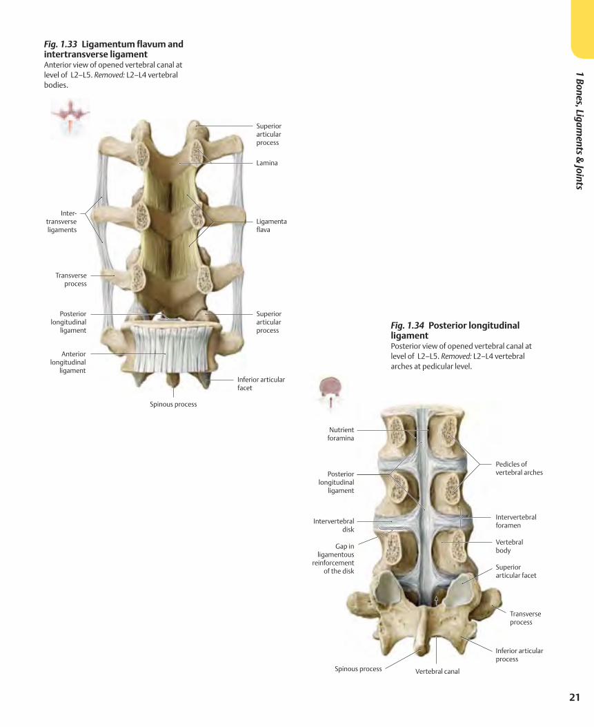
Fig. 1.33 Ligamentum flavum and intertransverse ligament Anterior view of opened vertebral canal at level of L2–L5. Removed: L2–L4 vertebral bodies.
Fig. 1.34 Posterior longitudinal ligament Posterior view of opened vertebral canal at level of L2–L5. Removed: L2–L4 vertebral arches at pedicular level.