Embed Size (px)
Citation preview
Revit family creation standards
Version 12

© copyright bimstore 2014
All rights reserved
No part of this publication may be reproduced, stored in a retrieval system, or transmitted in any form or by any means, electronic, mechanical, photocopying,
scanning or otherwise without the prior permission of bimstore
These standards are structured from content within the following documents:
BS8541 -Library objects for architecture, engineering and construction. PAS1192:2013
BS1192:4 - COBieBS1192:3 - Asset Management & Operation
Autodesk Revit Architecture 2010 Families Guide Autodesk Revit Model Content Style Guide
AEC (UK) BIM Standard for Autodesk Revit
bimstore bible (version 12) by bimstore Created August 2014 Printed August2014
bimstore bible
The purpose of this guide is to define bimstore guidelines and standards for model content creation in Revit Architecture, Revit MEP, and Revit Structure. Model content refers to the two-dimensional and three-dimensional standard component families that are used to create elements that represent manufactured or generic content (for example, windows, doors, furniture, and plumbing fixtures).
By following the guidelines and standards in this document, content creators will ensure the portability and performance of their content in a BIM process. This will meet the baseline standard to be hosted on bimstore, because we ensure that our components shall:
� Display uniformly regardless of context.
� Be a standard, complete, consistent, accurate and uniform representation of the components.
� Be compatible with recognised industry standards.
� Ensure the component is usable throughout the BIM process, from early conceptual design through to Facilities Management and operation of the building.
1.0 introducton
Note: These standards are specific for Autodesk Revit software only. Please refer to the bimstore bible - Archicad or bimstore bible - Bentley for more information on other formats.
2.0 planning a model familybimstore bible
When creating a Revit family, the intended use of the family in a project environment determines the extent to which it is designed. You can design all families to include a number of representations for use in different project views and project phases.
The type and size of the project that a family is intended for use in is a critical point to consider when deciding what representations should be included in the family and what level of detail each representation should have. The more detailed a family is, the larger its file size will be. The larger the file size, the slower the performance, loading, and regeneration time of the family will be. When considering the design intent of a family, use the following guidelines:
2.1. Determining the template to use
For objects typically hosted by other components, such as a window or light fixture, start with a host-based template. For example, for a window or door, use a wall-based template, such as Window.rft or Door.rft. How the family is hosted (or what it does or does not attach to) determines which template should be used to create the family. In general, the choice of a template is driven by the host of the object, with the following exceptions:
� Floor-based objects typically use a level-based template unless they are required to cut the floor. For example, Furniture objects are created with a level-based template.
� For objects that are designed to be used in more than one discipline, such as plumbing or lighting fixtures, use a host-based template that allows the greatest flexibility for all disciplines. For example, a lighting fixture used exclusively in an architectural discipline could be created with a ceiling or wall-based template, but for an engineering environment, a face-based template is required for the model linking workflow. Therefore, for a lighting fixture that will be used in both disciplines, use a face-based template.
2.2. Determine the family’s use
Before you even open Revit, grab a piece of paper and plan your family. Although it may be tempting to jump straight in and start building your family, this can cause you problems later. Some of the questions you will need to establish are:
� Is the family a generic family or a family based upon specific manufacturers’ content? – This is a fundamental question to establish early on. Generally a manufacturer’s content is created with fewer parameters than generic content. For example, if a manufacturer only makes one table size, then why add a parameter to change its length?
� What parameters does the family need? – Think about what parameters are required. Adding additional unnecessary parameters will increase model size and decrease its performance. Think about what parameters may require scheduling. By using the bimstore standard templates the minimum required parameters will already be created within the template.
� What template should you use? – See section 2.1. This is a critical decision that will affect how the family behaves, displays, and schedules within your model.
� Family Intent & Purpose – Establish what the family is going to be used for and model appropriately for its intended use. Is the family an all - purpose family that can be used from concept to construction or is it more targeted at a specific phase i.e. construction.
� Level of Detail – This is an important concept covered in section 2.3. Decide early on what the family representations will be at the different levels of detail (coarse, medium and fine).
Use the family planning checklist in appendix 01 to assist you in this process.
6 bimstore
2.3. Level of detail
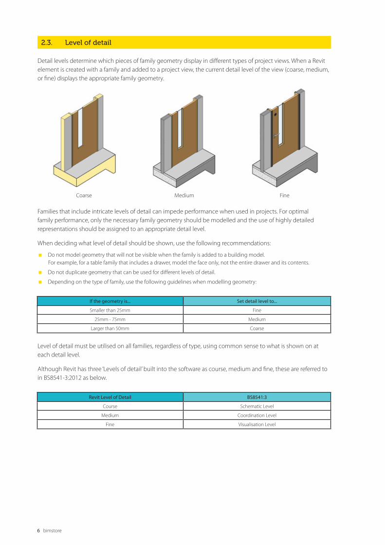
Detail levels determine which pieces of family geometry display in different types of project views. When a Revit element is created with a family and added to a project view, the current detail level of the view (coarse, medium, or fine) displays the appropriate family geometry.
Coarse Medium Fine
Families that include intricate levels of detail can impede performance when used in projects. For optimal family performance, only the necessary family geometry should be modelled and the use of highly detailed representations should be assigned to an appropriate detail level.
When deciding what level of detail should be shown, use the following recommendations:
� Do not model geometry that will not be visible when the family is added to a building model. For example, for a table family that includes a drawer, model the face only, not the entire drawer and its contents.
� Do not duplicate geometry that can be used for different levels of detail.
� Depending on the type of family, use the following guidelines when modelling geometry:
If the geometry is... Set detail level to...
Smaller than 25mm Fine
25mm - 75mm Medium
Larger than 50mm Coarse
Revit Level of Detail BS8541:3
Course Schematic Level
Medium Coordination Level
Fine Visualisation Level
Level of detail must be utilised on all families, regardless of type, using common sense to what is shown on at each detail level.
Although Revit has three ‘Levels of detail’ built into the software as course, medium and fine, these are referred to in BS8541-3:2012 as below.
2.4. Element visibility
Typically, the geometry of an element created by a family will change depending on the current project view. The visibility settings of the family determine in which project views elements created with the family will display.
In a plan view, you may want to see a 2D representation of the element. In a 3D or elevation view, you may want to display a fully detailed 3D representation of the element. In other views, you may want to hide the element. Limiting the visibility of highly detailed family geometry to only certain views can improve project performance.
2.5. Nesting families
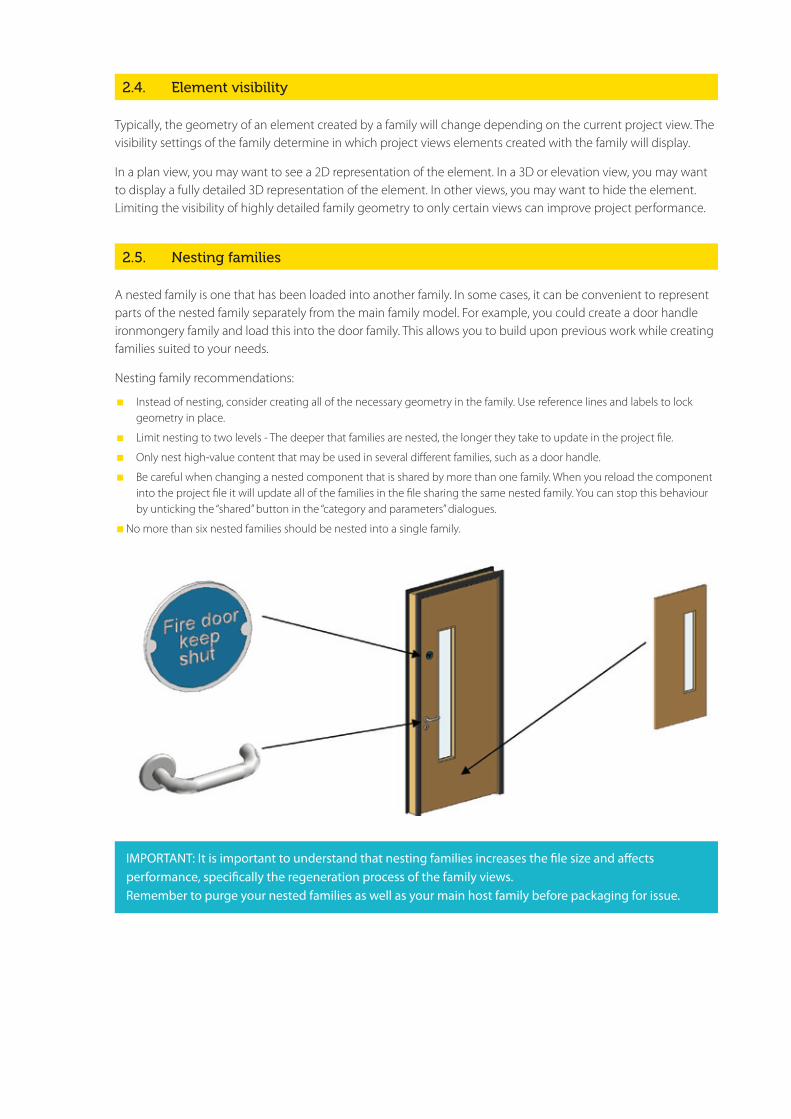
A nested family is one that has been loaded into another family. In some cases, it can be convenient to represent parts of the nested family separately from the main family model. For example, you could create a door handle ironmongery family and load this into the door family. This allows you to build upon previous work while creating families suited to your needs.
Nesting family recommendations:
� Instead of nesting, consider creating all of the necessary geometry in the family. Use reference lines and labels to lock geometry in place.
� Limit nesting to two levels - The deeper that families are nested, the longer they take to update in the project file.
� Only nest high-value content that may be used in several different families, such as a door handle.
� Be careful when changing a nested component that is shared by more than one family. When you reload the component into the project file it will update all of the families in the file sharing the same nested family. You can stop this behaviour by unticking the “shared” button in the “category and parameters” dialogues.
� No more than six nested families should be nested into a single family.
IMPORTANT: It is important to understand that nesting families increases the file size and affects performance, specifically the regeneration process of the family views. Remember to purge your nested families as well as your main host family before packaging for issue.

8 bimstore
2.7. Areas to avoid for optimal performance
Below are some of the common mistakes that are made when creating content for Autodesk Revit. After planning your family review this table to prevent you making the same mistakes.
Common mistakes when creating families... Recommended approach...
Lack of planning prior to family creation Before creating a family, use the guidelines outlined in 2.0 Planning a Revit Model Family
Unnecessary parametric relationships Before adding geometry to a family:
1) Plan the parametric relationships and create a reference plane skeleton that features the main parametric relationships.
2) Build only the parametric family behaviour that you need to avoid over-constraining the model.
High levels of geometric detail and underuse of visibility settings Use the guidelines in the Level of Detail and Element Visibility sections of this guide to avoid unnecessarily large family files
Use of geometry instead of symbolic lines in plan views In plan view representations, geometry usually can be represented with symbolic lines, rather than (solid) geometry. Using geometry instead of symbolic lines will create an unnecessarily larger family
Overuse of voids, formulas, and arrays Extensive use of voids, formulas, and arrays will add to the overall family size and affect its performance in projects
Use of too many nested families (families imported into other families)
Nest families to create geometry in other families only when necessary. Only use nested content to share objects among multiple families, for example, door hardware, muntin patterns, and so on
Large families with many types that do not include type catalogues The more types (particularly unused) the heavier the family. Create type catalogues for families that contain six or more types
Inadequate family testing See section 13.0 General Family Testing Guidelines
2.6. Family size
Although not as important as it was prior to Revit 2010, many large components can affect the performance of a Building Information Model.
It is recommended to keep the components’ file size as small as possible; however this must be considered carefully as one very large parametric family (that can be configured to almost any configuration) will be loaded into a project only once. The alternative would be many smaller individual families, but these combined can be larger (and just as cumbersome) as a single large flexible component.
It is recommended that a typical family be no larger than around 700kb, however every family and its functionality is unique so this can vary.
We recommend the following to keep your family as small as possible:
� Purge and audit your family prior to upload (Be careful not to remove any material types you may have added!)
� Keep nesting to a minimum, and ensure the nested objects are also purged and audited, including removing any un-used types!
� Limit the use of custom materials and bitmaps whenever possible.
� Only model what is required to an appropriate level of detail. You will excite no one with your threads on screws!
� Remove any CAD or images used while building your component, and purge to make double sure they’ve been removed!
� Never explode CAD into your family.
Before you create a model family, review the standards in this section, and then use the best practice workflow below to create your content.
This workflow helps to ensure that your content is created in the most efficient and least error prone manner.
1) Create a new family file (.rfa) with the appropriate bimstore family template.
2) Define subcategories for the family to help control the visibility of the family geometry.
3) Create the family skeleton, or framework, usually using reference planes or lines;
a) Define the origin (the insertion point) of the family. In most families the template will already have this defined.
b) Lay out reference planes to snap to when you sketch component geometry.
c) Add dimensions to specify parametric relationships.
d) Label dimensions to create type or instance parameters or 2D representation.
e) Test, or flex, the skeleton.
4) Define family type variations by specifying different parameters.
5) Add a single level of geometry in solids and voids, and constrain the geometry to reference planes.
6) Flex the new model (types and its hosts) to verify correct component behaviour.
7) Repeat previous steps until the family geometry is complete.
8) Specify 2D and 3D geometry display characteristics with subcategory and entity visibility settings.
9) Save the family, and then test it.
10) For large families that include many types (over 8), create a type catalogue
3.1. Prototyping
If you need to create a number of similar families, then plan and create a “prototype family”. Test the prototype family (section 13) in the family editor and in a project environment to identify any problem areas and in consistencies.
Correct any errors and inconsistencies and retest the family to ensure it works properly before creating any additional families. This prototype family can now stripped and used as a template and a benchmark for the additional families.
You can upload your prototype families to bimstore labs for testing and feedback by the bimstore community. www.bimstore.co.uk
3.0 content creation workflowbimstore bible

All content created by bimstore must be created in Metric. This is established at template selection, and as long as you are using the bimstore family template the units will be set to Metric.
Although families can be created as unit - specific (imperial or metric), Revit software stores all coordinates in universal units and displays specific units according to user preference. This means that:
� Units can be set to display as necessary for a target audience (i.e., display as decimal units for a civil engineering drawing or fractional units for an architectural drawing).
� Families created in imperial units may be loaded into and used in metric projects and vice versa.
Although reverse engineering someone else’s family can cause unforeseen problems, sometimes it is necessary. When reverse engineering a family, it may be necessary to change the units of the family to aid the reverse engineering process. For more information on how to do this refer to the Revit Help Documentation.
4.0 family unitsbimstore bible
Family names are the primary means of identifying families in the Revit software. bimstore family naming conventions are created in accordance with BS8541-1:2012, which ensure that families can be identified in 70 industry standards, bimstore and the Revit software itself . The naming conventions include descriptions that allow the user to search for families by element, by manufacture, and/ or base unites
5.1 Family (component) naming
Guidelines
� Create unique names for each family. For example, a fixed window family and a fixed door family cannot share the same name.
� Use natural language to name a family. The family name should describe how the family is identified in the real world (i.e, in catalogues, by manufacturer, etc).
� If possible, do not include the family category in the family name, unless the functional type is the same as the category (eg. window).
� Use ‘Title Casing’ (as with the title of a book) for family names, as they are case sensitive.
� Keep file names as short as possible. Family names must display in dialogues and in the Type Selector.
� When adding optional descriptions to family file names, consider the order in which the descriptions are listed to ensure that the family files display in the Project Browser in the most logical and intuitive order.
� Do not use spaces between words in filenames. To separate words within a syntax element (eg. Manufacturer or Descriptor). Use the underscore character (_).
� If a hyphen (-) is used to include a performance range, enclose the range in parentheses, for example, (230-250_Ton).
� If a type catalogue is to be used with a family, name the type catalogue (txt.file) with the same name as the family. See section 10.0 for additional information.
� If a system family (wall, roof, railing, floor, stair) the [function_type] field can be omitted as it is clear what the component is by the system selection.
� If the content is from an external source and not named in accordance with this guide then, the family must be renamed in accordance with this guide.
Format
All families created for bimstore must be named in the following format: <Functional Type> - <Subtype> - <Manufacture> - <Descriptor 1> - <2D if necessary>An example family for an internal flush face door made by a company called Laidlaw would be for example- “Door-Internal-Laidlaw_Flush_Face”.A thermally broken aluminium Casement window made by a company called Acme would be -”Window-Casement-Acme-Thermally_broken_Aluminium”.
Further examples:
� Window-Double_Hung-Acme-Tilting_Sash.rfa Fountain-Drinking-Acme-Polished_Chrome.rfa
� Chiller-Air_Cooled-Acme-Low_Profile.rfa Window-Double_Hung-Generic-Wood.rfa
5.0 family namingbimstore bible
bimstore 11
Field/Component Required or Optional Description
<Functional Type> Required Names the element that the family created (for example, Door or Window)
<Subtype> As needed Names the part type, for example, for a window the subtype could be Case-ment. In a door it would be external or internal.
<Manufacturer/Generic> Required Manufacturer name, generic families may substitute the Manufacturer name with “Generic”.
<Descriptor 1> Required Brief plain-English description of the component.
<2D> Required Use only 2D families
12 bimstore
5.2. Type naming conventions
All families must include one predefined type. For families that create real-world objects that are available in standard sizes, predefined types should be generated. Unless they represent nominal sizes, type names should include units or capacity, and include a unit indicator.
When naming a family type, use the format and rules below:
Guidelines
� Do not include the family name or category in the type name.
� Type names should mirror actual usage.
� Type names should indicate the key differences between types (size, count, material) and, when applicable, reflect standard sizes. In some cases, you may base names on size difference, but use common terms rather than numbers.
� When types are named by size, use dimensions only. Avoid the use of characters or words. (h, w, d, or height, width, depth).
� Type names should include units or capacity and a unit indicator, unless they represent nominal sizes.
� Metric types should reflect the local unit standard, unless the types are intended to be generic.
� Keep type names as short as possible. Type names must display in dialogues and in the Type Selector.
Format
Unless there is a market-specific reason to do otherwise, use the following general order in type names:
For doors and windows: <width> x <height> For casework and furniture: <width> x <depth> x <height>
For other element types: <width> x <depth>
Further examples for an imperial window:
� 1200mm x 600mm
� 1500mm x 600mm
� 1800mm x 600mm
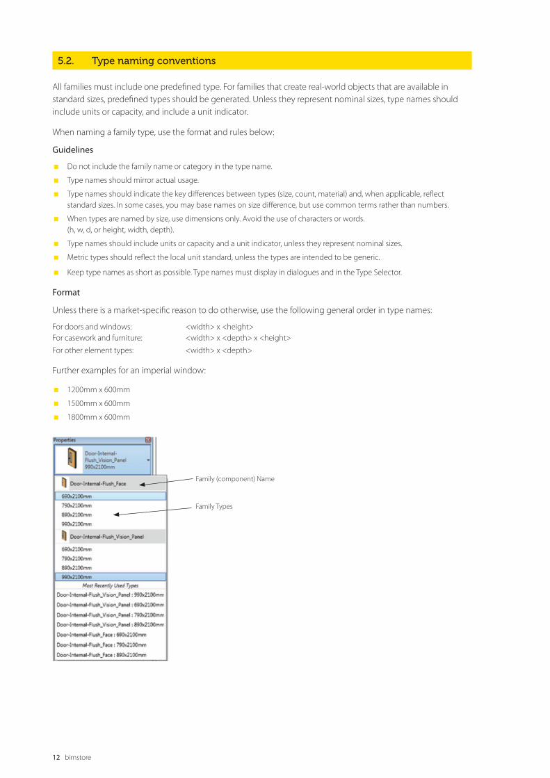
Family (component) Name
Family Types

All families, including generic families, must be assigned to appropriate categories and subcategories. When a family is created, it is assigned a category. The category defines its top level of identification (for example, Door, Window, or Casework) within the project environment. When the family is used in a project, the family can be located in the Project Browser under its category, and elements created by the family types will schedule by its category. The line weight, line colour, line pattern, and material assignment of the family geometry can also be assigned by category.
To display different line weights, line colours, line patterns, and material assignments for different geometric components of the family (for example, the frame, sash, mullions, and glass that comprise a window), the components can be assigned to subcategories within the family category.
Categories are predefined in Revit software and cannot be created or changed by the user. Subcategories are predefined in some families, but other subcategories can be created in families as needed.
For the most part, the subcategories required will be automatically defined in the family template.
6.0 category and subcategory
standards and usage
bimstore bible

Families contain parameters that not only create the family geometry, but identify or classify the elements that are created by the family. All families have predefined parameters that you assign values or data to, but you can add parameters that are not predefined in Revit software.
The bimstore template that you use to create your family (see section 2.1) will contain the minimum parameters required to meet these family creation guidelines and industry standards such as BS8541-4:2012. Should you wish to add additional parameters, then ensure that these are created as ‘shared parameters’. These should be defined in an shared parameter .txt file that is independent of family and project files.
If you add a shared parameter which you think would be useful for future families you can request that the parameter is added to the bimstore standard templates via our contact form. If you are adding shared parameters to system files, you must ensure that the file is included with the upload to bimstore as a txt file.
‘Family Parameters; should only be used in place of shared parameters in situation where the data is not required to appear in schedules or tags, or where used formula prevents shared parameter use.
7.0 bimstore parameter usagebimstore bible
7.1. Parameter naming convention
Consistent parameter naming enables easier and more comprehensive parametric searching. Create parameters only when variation creates meaningfully differentiated types that represent real-world possibilities.
Guidelines
� Use standard approved parameter names when available.
� Keep parameter names as short as possible.
� Avoid abbreviation and truncation when possible.
� Use ‘Title Casing’ (as with the title of a book) for parameter names, as they are case sensitive (e.g., Coefficient of Performance; Point of Shipment; High and Low Pressure Gas Connection Diameter).
� Do not change label names provided by the bimstore family templates.
� Parameter names that you reuse to create equalities should be carefully checked for name coherence.
� Use the most common descriptor for a group of parameters as the first part of the name so that the parameters sort logically (e.g., Filter Face Area; Filter Efficiency).
� Avoid using symbols in parameter names, including: + - / \ * ( ) “ ‘ < > | ^ $ { } [ ].
� Do not include units in the name of a parameter (e.g., Supply Air Flow CFM).
� Using the terms Actual or Design:
a) Actual – describes the actual value the system definition requires. “Actual” parameters are linked to connectors and are often used for parameters that define flow rates, for example, Actual Supply Air Flow; Actual Chilled Water Flow.
b) Design – describes what the product is designed to do, for example, Design Ventilation Air Flow; Design Return Air Flow.
� Name Yes/No parameters so they imply that they return a Yes/No value, for example:
a) Has Handle
b) Is Energy Efficient
c) Show Hoods
Format
<Function/Object> <Type of measurement/Descriptor> <Function/Object> required if the parameter applies to a sub-component rather than the entire family. <Type of measurement/Descriptor> required for all parameters to describe the value being passed.

16 bimstore
7.2. Correct use of the bimstore parameters
By default you will notice three parameters under the “other” category of the template. Both these parameters MUST be completed before the family is uploaded to bimstore or used in a ‘live’ project environment.
Parameter name Description Type of parameter
_current revision Current bimstore revision of the current family. This is numerical and should begin at 1.
System (Integer)
_created by This should read “www.bimstore.co.uk” or your own URL if created inhouse. System (URL)
_distributed by This should read “www.bimstore.co.uk” System (URL)
_author The authors name, i.e. your name System (Text)
_bimspec_guid Leave this field blank, this will be completed by the bimstore team System (Integer)
� “_current revision” – This parameter should be maintained when editing and updating families. This should start at 1 and progress per family revision
� “_created by” – This parameter should always reference the bimstore website.
� “_author” – This should by the name of the person who made the original family and not changed when the family is revised. You may use a URL in this field to link to a company website if appropriate.
� “_bimspec_guid” - this is used by bimstore to identify this component and link it with property dimensions in bimstore and other future software packages.
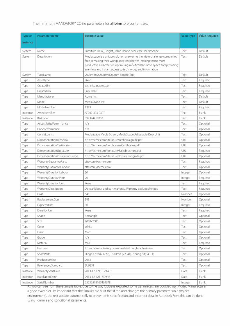
7.3. Cobie Parameters
All bimstore content must have the correct COBie parameters. These parameters are used to create COBie Data Drops (a standard format Excel file) that can be utilised by third party software and organizations.
COBie is quickly becoming the standard information schema in the UK and many organizations - including the UK government - are now asking for a Completed COBie file as a deliverable upon occupancy of a building.
It is important that all bimstore content is compatible with COBie (Defined in BS1192:4), and that when a COBie file is created from the building information model the data is transferred in the correct schema.
Not all COBie fields require a value, for example “WarrantyStartDate” will be entered by the contractor or client upon handover of COBie. However it is important that this parameter exists when its exported.
Type or
instance
Parameter name Example Value Value Type Value Required
System Name Furniture-Desk_Height_Table-Round-Steelcase-MediaScape Text Default
System Description Mediascape is a unique solution answering the triple challenge companies’ face in making their workplaces work better -making teams more productive and creative, optimising m² of collaborative space and providing seamless and instant access to technology and information.
Text Default
System TypeName 2000mmx2000mmx900mm Square Top Text Default
Type AssetType Fixed Text Required
Type CreatedBy [email protected] Text Required
Type CreatedOn ‘July 2014’ Text Required
Type Manufacturer Acme Inc Text Default
Type Model MediaScape MV Text Default
Type ModelNumber 9383 Text Required
Instance AssetIdentifier AT002-323-232T Text Blank
Instance BarCode 392324411002 Text Blank
Type AccessibilityPerformance n/a Text Optional
Type CodePerformance n/a Text Optional
Type Consitituents MediaScape Media Screen, MediaScape Adjustable Desk Unit Text Optional
Type DocumentationTechnical http://acme.com/literature/Technicalguide.pdf URL Optional
Type DocumentationCertificates http://acme.com/certificates/Certificates.pdf URL Optional
Type DocumentationLiterature http://acme.com/literature/Salesbrochure.pdf URL Required
Type DocumentationInstallationGuide http://acme.com/literature/Installationguide.pdf URL Optional
Type WarrantyGuarantorParts [email protected] Text Required
Type WarrantyGuarantorLabour [email protected] Text Optional
Type WarrantyDurationLabour 20 Integer Optional
Type WarrantyDurationParts 20 Integer Required
Type WarrantyDurationUnit Years Text Required
Type WarrantyDescription 20 year labour and part warranty. Warranty excludes hinges Text Required
Type Cost 545 Number Optional
Type ReplacementCost 545 Number Optional
Type ExpectedLife 30 Integer Required
Type DurationUnit Years Text Required
Type Shape Rectangle Text Optional
Type Size 2000x2000 Text Optional
Type Color White Text Optional
Type Finish Matt Text Optional
Type Grade n/a Text Optional
Type Material MDF Text Required
Type Features Extendable table top, power assisted height adjustment Text Optional
Type SpareParts Hinge Cover(23232), USB Port (22844), Spring Kit(34311) Text Optional
Type ProductionYear 2013 Text Optional
Type ReferencedStandard EU9231 Text Optional
Instance WarrantyStartDate 2013-12-12T13:29:45 Date Blank
Instance InstallationDate 2013-12-12T13:29:45 Date Blank
Instance SerialNumber 65536578767464678 Integer BlankAs you can see from the example table, due to the way COBie is exported some parameters are doubled up (Model, Manufacturer a good example). Its important that the families are built that if the user changes the primary parameter (in a project environment), the rest update automatically to prevent mis-specification and incorrect data. In Autodesk Revit this can be done using Formula and conditional statements.
The minimum MANDATORY COBie parameters for all bimstore content are:
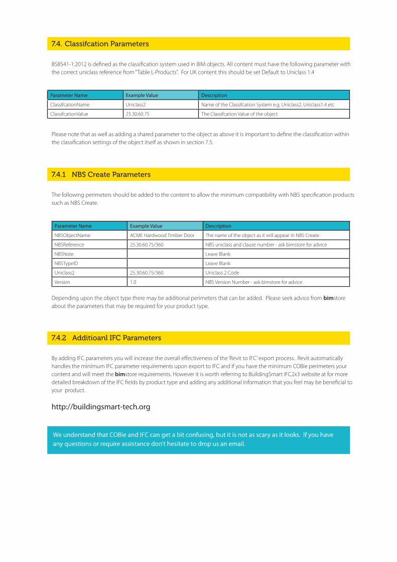
7.4. Classifcation Parameters
BS8541-1:2012 is defined as the classification system used in BIM objects. All content must have the following parameter with the correct uniclass reference from “Table L-Products”. For UK content this should be set Default to Uniclass 1.4
Parameter Name Example Value Description
ClassifcationName Uniclass2 Name of the Classifcation System e.g. Uniclass2, Uniclass1.4 etc
ClassifcationValue 25.30.60.75 The Classifcation Value of the object
Please note that as well as adding a shared parameter to the object as above it is important to define the classification within the classification settings of the object itself as shown in section 7.5.
7.4.1 NBS Create Parameters
The following perimeters should be added to the content to allow the minimum compatibility with NBS specification products such as NBS Create.
Parameter Name Example Value Description
NBSObjectName ACME Hardwood Timber Door The name of the object as it will appear in NBS Create
NBSReference 25.30.60.75/360 NBS uniclass and clause number - ask bimstore for advice
NBSNote Leave Blank
NBSTypeID Leave Blank
Uniclass2 25.30.60.75/360 Uniclass 2 Code
Version 1.0 NBS Version Number - ask bimstore for advice
Depending upon the object type there may be additional perimeters that can be added. Please seek advice from bimstore about the parameters that may be required for your product type.
7.4.2 Additioanl IFC Parameters
By adding IFC parameters you will increase the overall effectiveness of the ‘Revit to IFC’ export process. Revit automatically handles the minimum IFC parameter requirements upon export to IFC and if you have the minimum COBie perimeters your content and will meet the bimstore requirements. However it is worth referring to BuildingSmart IFC2x3 website at for more detailed breakdown of the IFC fields by product type and adding any additional information that you feel may be beneficial to your product.
http://buildingsmart-tech.org
We understand that COBie and IFC can get a bit confusing, but it is not as scary as it looks. If you have any questions or require assistance don’t hesitate to drop us an email.
19 bimstore
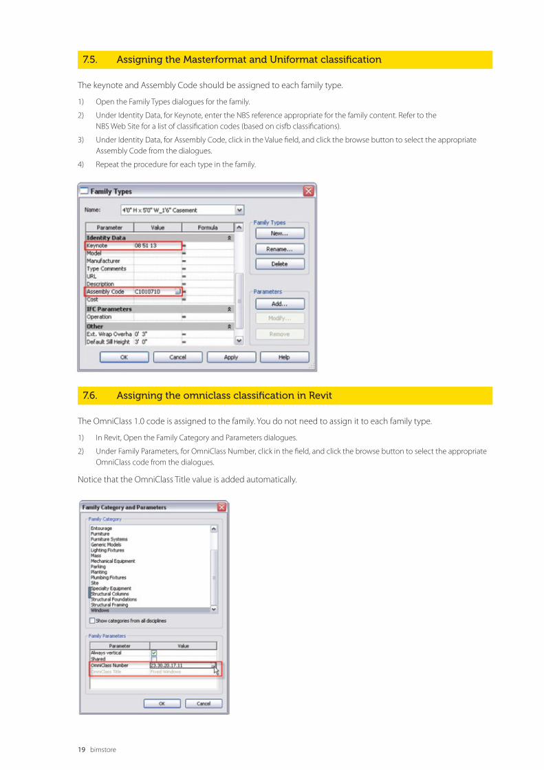
7.6. Assigning the omniclass classification in Revit
The OmniClass 1.0 code is assigned to the family. You do not need to assign it to each family type.
1) In Revit, Open the Family Category and Parameters dialogues.
2) Under Family Parameters, for OmniClass Number, click in the field, and click the browse button to select the appropriate OmniClass code from the dialogues.
Notice that the OmniClass Title value is added automatically.
7.5. Assigning the Masterformat and Uniformat classification
The keynote and Assembly Code should be assigned to each family type.
1) Open the Family Types dialogues for the family.
2) Under Identity Data, for Keynote, enter the NBS reference appropriate for the family content. Refer to the NBS Web Site for a list of classification codes (based on cisfb classifications).
3) Under Identity Data, for Assembly Code, click in the Value field, and click the browse button to select the appropriate Assembly Code from the dialogues.
4) Repeat the procedure for each type in the family.
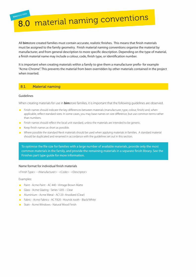
All bimstore created families must contain accurate, realistic finishes. This means that finish materials must be assigned to the family geometry. Finish material naming conventions organise the material by manufacturer, and from general description to more specific description. Depending on the type of material, a finish material name may include a colour, code, finish type, or identification number.
It is important when creating materials within a family to give them a manufacturer prefix- for example “Acme-Chrome”. This prevents the material from been overridden by other materials contained in the project when inserted.
8.1. Material naming
Guidelines
When creating materials for use in bimstore families, it is important that the following guidelines are observed.
� Finish names should indicate the key differences between materials (manufacturer, type, colour, finish) and, when applicable, reflect standard sizes. In some cases, you may base names on size difference, but use common terms rather than numbers.
� Finish names should reflect the local unit standard, unless the materials are intended to be generic.
� Keep finish names as short as possible.
� Where possible the standard Revit materials should be used when applying materials in families. A standard material should be duplicated and renamed in accordance with the guidelines set out in this section.
To optimise the file size for families with a large number of available materials, provide only the most common materials in the family, and provide the remaining materials in a separate finish library. See the Finishes part type guide for more information.
Name format for individual finish materials
<Finish Type> - <Manufacturer> - <Code> - <Descriptor>
Examples:
� Paint - Acme Paint - AC 440 - Vintage Brown Matte
� Glass - Acme Glazing - Series 1205 – Clear
� Aluminium - Acme Metal - AC120 -Anodized (Clear)
� Fabric - Acme Fabrics - AC F820 - Hounds tooth - Black/White
� Stain - Acme Windows - Natural Wood Finish
8.0 material naming conventionsbimstore bible
21 bimstore
8.2. Material ‘image’ naming
If a standard material can not be modified to suit, then a custom material may be made. These materials can consist of a number of images, bump, cut-out maps etc.
These guidelines must be followed for the creation and naming of these images:
� Create unique names for each unique material image.
� Capitalise the leading letters in each portion of the material name.
� Do not use spaces between words in file names. To separate words within a syntax element (e.g., Manufacturer or Descriptor), use the underscore character (_).
� Acceptable file formats for material images include: bmp, jpg, jpeg and png.
� Provide a readme file to describe where the image files must be located and how to map Revit to the “Revit Manufacturer Library“ folder in the Rendering Options dialogues. This file must be included in the .zip file when it is uploaded to
bimstore.
Examples:
Image File:
Paint-Acme_Paint-AC_440-Vintage_Brown_Matte.jpg
Stain-Acme_Windows-Natural_Wood_Finish.jpg
Bump Image File:
-bump.jpg
Cutouts/Perforations:
cutout.jpg
Aluminum-Acme_Fencing-AC120-Anodized-cutout.jpg
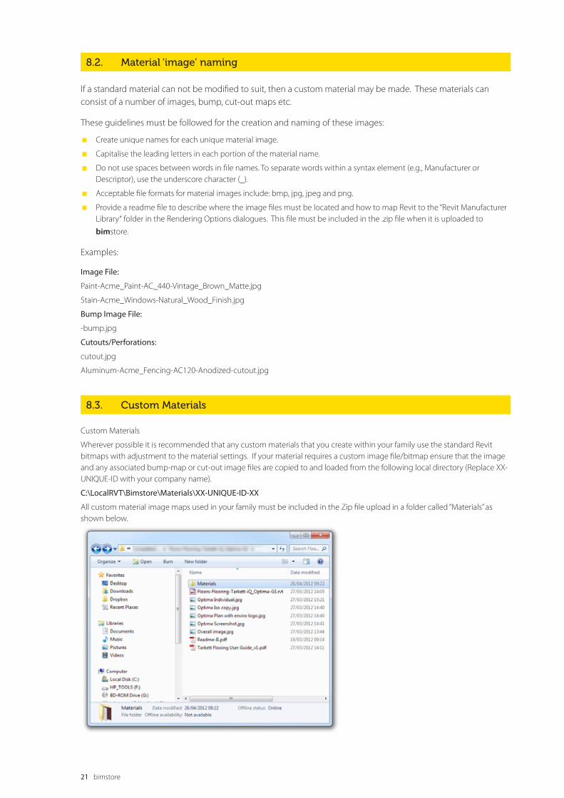
8.3. Custom Materials
Custom Materials
Wherever possible it is recommended that any custom materials that you create within your family use the standard Revit bitmaps with adjustment to the material settings. If your material requires a custom image file/bitmap ensure that the image and any associated bump-map or cut-out image files are copied to and loaded from the following local directory (Replace XX-UNIQUE-ID with your company name).
C:\LocalRVT\Bimstore\Materials\XX-UNIQUE-ID-XX
All custom material image maps used in your family must be included in the Zip file upload in a folder called “Materials” as shown below.
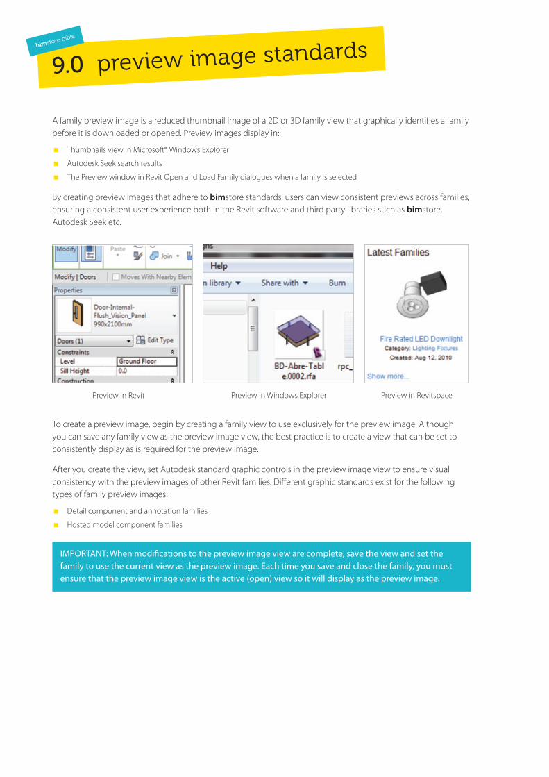
A family preview image is a reduced thumbnail image of a 2D or 3D family view that graphically identifies a family before it is downloaded or opened. Preview images display in:
� Thumbnails view in Microsoft® Windows Explorer
� Autodesk Seek search results
� The Preview window in Revit Open and Load Family dialogues when a family is selected
By creating preview images that adhere to bimstore standards, users can view consistent previews across families, ensuring a consistent user experience both in the Revit software and third party libraries such as bimstore, Autodesk Seek etc.
Preview in Revit Preview in Windows Explorer Preview in Revitspace
To create a preview image, begin by creating a family view to use exclusively for the preview image. Although you can save any family view as the preview image view, the best practice is to create a view that can be set to consistently display as is required for the preview image.
After you create the view, set Autodesk standard graphic controls in the preview image view to ensure visual consistency with the preview images of other Revit families. Different graphic standards exist for the following types of family preview images:
� Detail component and annotation families
� Hosted model component families
IMPORTANT: When modifications to the preview image view are complete, save the view and set the family to use the current view as the preview image. Each time you save and close the family, you must ensure that the preview image view is the active (open) view so it will display as the preview image.
9.0 preview image standardsbimstore bible
23 bimstore
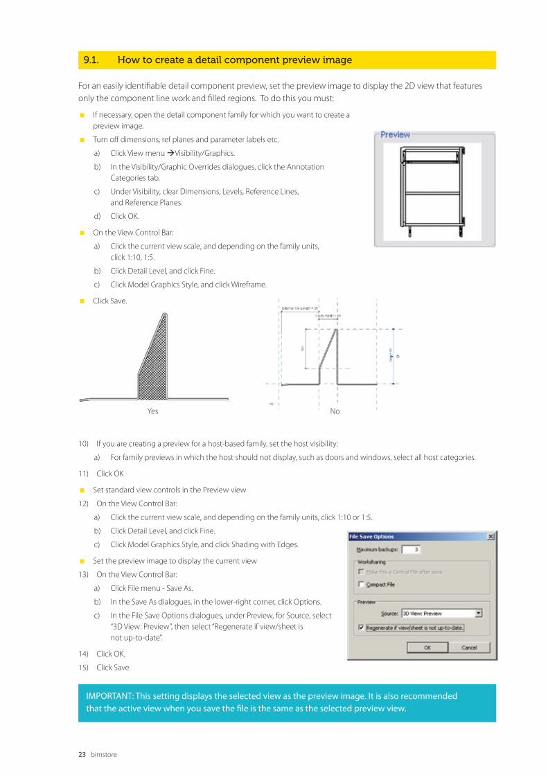
9.1. How to create a detail component preview image
For an easily identifiable detail component preview, set the preview image to display the 2D view that features only the component line work and filled regions. To do this you must:
� If necessary, open the detail component family for which you want to create a preview image.
� Turn off dimensions, ref planes and parameter labels etc.
a) Click View menu Visibility/Graphics.
b) In the Visibility/Graphic Overrides dialogues, click the Annotation Categories tab.
c) Under Visibility, clear Dimensions, Levels, Reference Lines, and Reference Planes.
d) Click OK.
� On the View Control Bar:
a) Click the current view scale, and depending on the family units, click 1:10, 1:5.
b) Click Detail Level, and click Fine.
c) Click Model Graphics Style, and click Wireframe.
� Click Save.
Yes No
10) If you are creating a preview for a host-based family, set the host visibility:
a) For family previews in which the host should not display, such as doors and windows, select all host categories.
11) Click OK
� Set standard view controls in the Preview view
12) On the View Control Bar:
a) Click the current view scale, and depending on the family units, click 1:10 or 1:5.
b) Click Detail Level, and click Fine.
c) Click Model Graphics Style, and click Shading with Edges.
� Set the preview image to display the current view
13) On the View Control Bar:
a) Click File menu - Save As.
b) In the Save As dialogues, in the lower-right corner, click Options.
c) In the File Save Options dialogues, under Preview, for Source, select “3D View: Preview”, then select “Regenerate if view/sheet is not up-to-date”.
14) Click OK.
15) Click Save.
IMPORTANT: This setting displays the selected view as the preview image. It is also recommended that the active view when you save the file is the same as the selected preview view.
24 bimstore
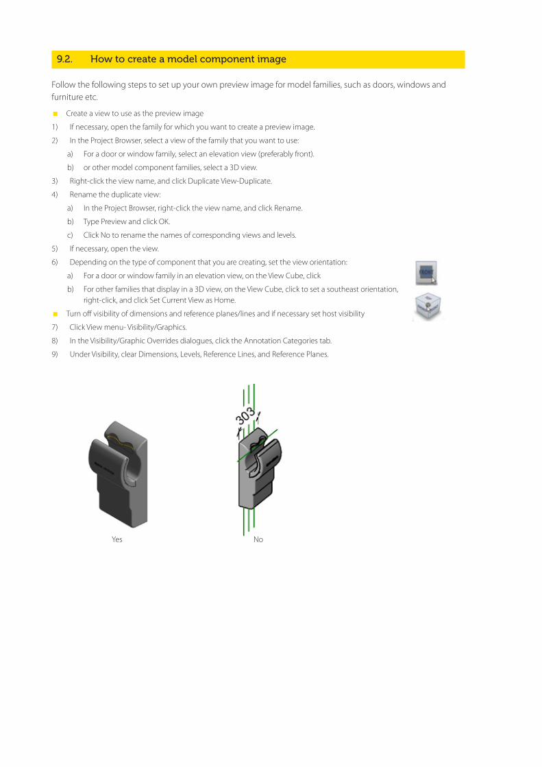
9.2. How to create a model component image
Follow the following steps to set up your own preview image for model families, such as doors, windows and furniture etc.
� Create a view to use as the preview image
1) If necessary, open the family for which you want to create a preview image.
2) In the Project Browser, select a view of the family that you want to use:
a) For a door or window family, select an elevation view (preferably front).
b) or other model component families, select a 3D view.
3) Right-click the view name, and click Duplicate View-Duplicate.
4) Rename the duplicate view:
a) In the Project Browser, right-click the view name, and click Rename.
b) Type Preview and click OK.
c) Click No to rename the names of corresponding views and levels.
5) If necessary, open the view.
6) Depending on the type of component that you are creating, set the view orientation:
a) For a door or window family in an elevation view, on the View Cube, click
b) For other families that display in a 3D view, on the View Cube, click to set a southeast orientation, right-click, and click Set Current View as Home.
� Turn off visibility of dimensions and reference planes/lines and if necessary set host visibility
7) Click View menu- Visibility/Graphics.
8) In the Visibility/Graphic Overrides dialogues, click the Annotation Categories tab.
9) Under Visibility, clear Dimensions, Levels, Reference Lines, and Reference Planes.
Yes No

A type catalogue is a comma-delimited .txt file that, when placed in the same directory as a family, displays a list of family types before the family is loaded into a project. You can select and load only the family types that the current project requires, avoiding an unnecessary increase in project size from unused types and a long list of types in the Type Selector. The type catalogue also provides an external means of editing the family, as you can remove and add parameters and types in the catalogue file (.txt).
Only use ‘Type Catalogues’ when your family contains more than 6 pre configured family types. When your family contains less than 6 family types a type catalogue should NOT be used and the types build
10.1. Type catalogue standards
Use the following standards when creating type catalogues:
� Use any text editor to create type catalogues.
� Create type catalogues ONLY for families that contain eight or more types.
� Name a type catalogue file (.txt) with the same name as the family file (.rfa) that it supports.
� Ensure that parameters in type catalogues are test loaded by the family for which you create the type catalogue. If the parameters are not used, the family will not load.
� When uploading family to bimstore ensure that the type catalogue is included in the .zip upload.
For information on creating a type catalogue, see “Creating Type Catalogues” in the Revit Help and Families Guide.
10.0 type catalogue standards
and usage
bimstore bible
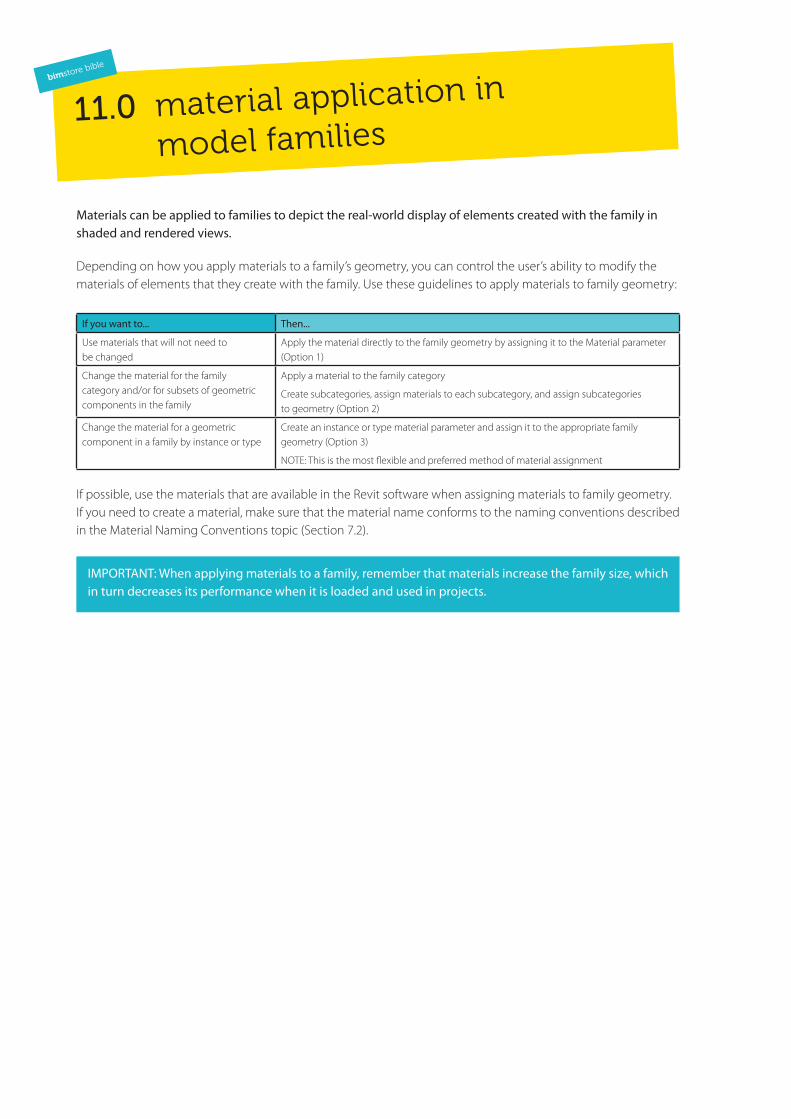
Materials can be applied to families to depict the real-world display of elements created with the family in shaded and rendered views.
Depending on how you apply materials to a family’s geometry, you can control the user’s ability to modify the materials of elements that they create with the family. Use these guidelines to apply materials to family geometry:
If you want to... Then...
Use materials that will not need to be changed
Apply the material directly to the family geometry by assigning it to the Material parameter (Option 1)
Change the material for the family category and/or for subsets of geometric components in the family
Apply a material to the family category
Create subcategories, assign materials to each subcategory, and assign subcategories to geometry (Option 2)
Change the material for a geometric component in a family by instance or type
Create an instance or type material parameter and assign it to the appropriate family geometry (Option 3)
NOTE: This is the most flexible and preferred method of material assignment
If possible, use the materials that are available in the Revit software when assigning materials to family geometry. If you need to create a material, make sure that the material name conforms to the naming conventions described in the Material Naming Conventions topic (Section 7.2).
IMPORTANT: When applying materials to a family, remember that materials increase the family size, which in turn decreases its performance when it is loaded and used in projects.
11.0 material application in
model families
bimstore bible

bimstore 27 bimstore
11.1. Option 1 – Applying materials with the material parameter
You can apply materials directly to some or all of the family geometry in the Family Editor. Each piece of family geometry has a default Material parameter to which you can assign materials.
Use this method when
The material of the family geometry is unlikely to change, such as for a manufactured component that is supplied with a single standard material.
Result
When you create elements in a project with the family, you cannot:
� change the element materials without editing the family
� change the material for instances or types of the family
� change the materials by assigning a material to the element category
11.2. Option 2 – Apply materials to a family geometry by category and subcategory
You can apply materials to all or select pieces of family geometry by subcategory. Subcategories are categories that exist within the family category. You can assign different pieces of family geometry to each subcategory, and then apply a different material to each subcategory. To apply material to geometry that is not assigned to a subcategory, you can apply materials by the family category.
Use this method when
You want to be able to apply different materials to different family components by category or subcategory.
Result
When you create an element in a project with the family:
� You can change the materials assigned to each subcategory or category.
11.3. Apply materials to family geometry by category and subcategory
You can create and assign a custom instance or type material parameter to family geometry. This is the most flexible option to use when applying materials to your family geometry.
Use this method when
� To allow the user to change family materials by instance or by type.
� By setting the material parameter to <by category> this option can also allow the elements to be updated by subcategory or category.
Result
When you create an element with the family in a project, the parameter gives you the option to change a material for an instance of the element or for each type of element that you create.

In Revit MEP, the connector connects the single family component with other components to create MEP systems. Without a connector, a family would just be a static placeholder.
If you are creating any electrical, plumbing or mechanical content then you must include the relevant MEP connectors. Even if you are unsure of the exact parameter fields, the connector must still be added, to comply with the bimstore standards.
Unless you are creating a Revit MEP component, it may be possible to skip this section.
MEP Electrical connector MEP Duct connector
12.1. Adding a connector
1) Click the tool for the connector you wish to add (Electrical Connector, Duct Connector, or Pipe Connector).
2) Click to place the connector in the drawing area.
RME provides two ways to place the connector, placing it on a face or on a work plane. If you select the Place on Face option, the connector is automatically added to the centre of the face of the geometry and moves with the face. If the geometry is deleted, the connector is also deleted.
BEST PRACTICE: Place connectors on a face rather than on a work plane.
12.0 adding MEP connectors
in families
bimstore bible

bimstore 29 bimstore
12.2. Connector direction
For duct/pipe connectors, an arrow, perpendicular to the surface, displays. The direction that the arrow is pointing is also the direction in which the connecting duct/pipe will be drawn. As the picture shows, vertical duct can be drawn from an up connector in an air terminal.
NOTE: The arrow does not represent the flow direction.
12.3. Primary Connector
By default, the first connector in each domain is assigned as the primary connector. In the following image, you can easily identify the primary connector (connector 1) by the cross symbol. The Re-assign Primary tool allows you to reassign the primary connector, as required.
The primary connector of pipe and duct fittings should be located at coordinates (-1, 0, 0). In the following image of the plan view of a P-Trap, connector 1 is the primary connector. For other family types, the location of the primary connector is not important.
30 bimstore
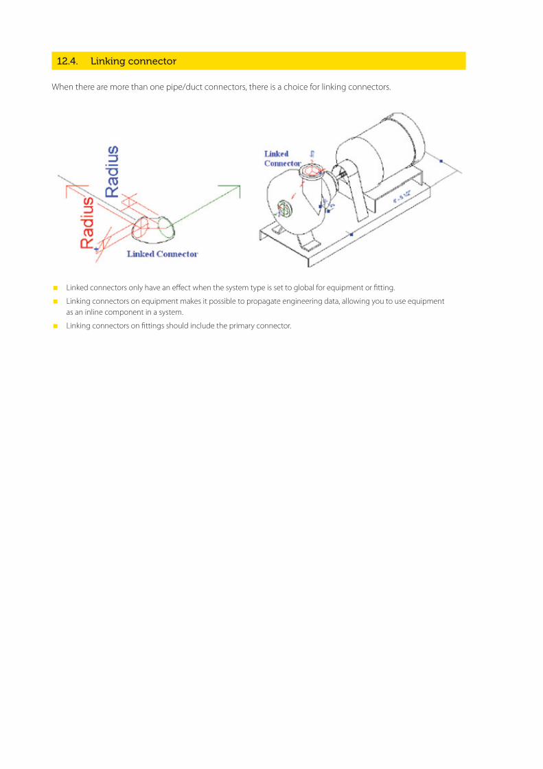
12.4. Linking connector
When there are more than one pipe/duct connectors, there is a choice for linking connectors.
� Linked connectors only have an effect when the system type is set to global for equipment or fitting.
� Linking connectors on equipment makes it possible to propagate engineering data, allowing you to use equipment as an inline component in a system.
� Linking connectors on fittings should include the primary connector.
Perform general testing on a family when it is:
� open in the Family Editor
� loaded into a project
Use the criteria in the checklists below to test families in each of the above environments. When testing families in projects, it is strongly recommended that you:
� Test families in projects that match the design intent of the family. For example, test a window family that is designed to be placed in a large commercial building in a large commercial project.
� Content that is designed to work in more than one Revit discipline must be tested in all applicable disciplines. For example, for a lighting fixture, test the connectors in Revit MEP, and verify that the fixture casts light as expected when rendering in Revit Architecture.
13.1. Family editor testing criteria
� Test all family parameters to ensure that the geometry flexes/adjusts correctly when the family parameters are modified.
� Test all family types – change the type, apply it, and inspect the geometry to verify that the dimensions and relationships are maintained.
� In a host-based family, verify that the host flexes as expected. Change the host thickness and ensure that the family geometry adjusts appropriately.
� Verify that the family preview image is using the Preview view.
� Check all views to ensure that the family displays appropriately in different detail levels and when different Model Graphics styles are applied.
� Test constraints:
a) Test the handles on the edge of the geometry and make sure that all geometry is constrained to either a reference plane or a reference line.
b) Test the dimension parameter to make sure that the reference plane or line is being adjusted by the parameter and not the actual geometry.
13.0 general family testing guidelinesbimstore bible
13.2. Project testing criteria for Revit Architecture
These are items to be checked in families created for primary use in Revit Architecture.
For all families:
� Inspect the family appearance in all views (plan, reflected ceiling plan, elevation, Section, 3D) at all detail levels (Coarse, Medium, Fine).
� Inspect the family appearance in different Model Graphics Styles: Wireframe, Hidden Line, Shading, and Shading with Edges.
� Test all family types – change the type, apply it, and inspect the geometry to verify that the dimensions and relationships are maintained.
� Create new types and modify all parameters, checking all views for anomalies.
� Modify all material assignments to verify that materials are associated to the geometry correctly. TIP: To better inspect family geometry, modify all material type parameters to glass. Also, if any of the family geometry does not display as glass, then a material parameter is assigned incorrectly.
� Modify category and subcategory materials to verify the family is not using material type parameters.
For hosted families:
� Place hosted families into the provided host thicknesses and confirm families work in all hosts appropriate to the families use, including in-place walls and mass elements.
� Modify the host thickness by 25% - 400%, and check for unconnected geometry and/or plan representations that may be disconnected from the geometry.
� Re-inspect the family appearance in all views to ensure that the geometry displays as expected.
� Dimension to all references and snap all references to walls.
� Create a test rendering.
Test the following commands on geometry created in the family:
� Copy/Paste
� Rotate
� Mirror
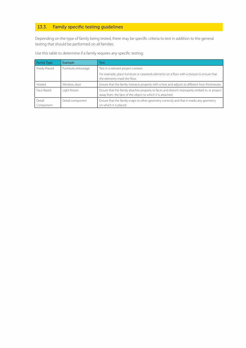
13.3. Family specific testing guidelines
Depending on the type of family being tested, there may be specific criteria to test in addition to the general testing that should be performed on all families.
Use this table to determine if a family requires any specific testing:
Family Type Example Test
Freely-Placed Furniture, entourage Test in a relevant project context.
For example, place furniture or casework elements on a floor with a texture to ensure that the elements mask the floor.
Hosted Window, door Ensure that the family interacts properly with a host and adjusts to different host thicknesses.
Face-Based Light fixture Ensure that the family attaches properly to faces and doesn’t improperly embed in, or project away from, the face of the object to which it is attached.
Detail Component
Detail component Ensure that the family snaps to other geometry correctly and that it masks any geometry on which it is placed.

In order to distribute your content using the bimstore.co.uk portal, it must meet the standards outlined in this document. When you are satisfied that it does, you can make your submission to the team for verification, following which it will be uploaded to the site and will appear in the listings and search results.
Once you are ready to submit your content, please contact [email protected] who will walk you through the submission process.
Our main goal at bimstore is to distribute high-quality, manufacturer-specific content to the construction industry. We trust that you understand that these processes reinforce that commitment and safeguard the integrity of this site as an industry leader in the distribution of BIM components.
14.0 distributing contentbimstore bible


Content Creation Checklist
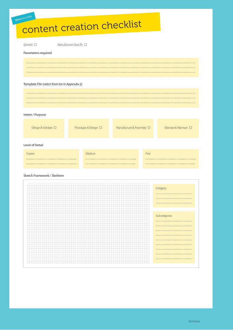
content creation checklistbimstore bible
bimstore
bimstore bible
Generic Manufacture Specific
Parameters required
Checklist
.......................................................................................................................................................................................................................................................................................
.......................................................................................................................................................................................................................................................................................
.......................................................................................................................................................................................................................................................................................
Template File (select from list in Appendix 2)
.......................................................................................................................................................................................................................................................................................
.......................................................................................................................................................................................................................................................................................
.......................................................................................................................................................................................................................................................................................
Intent / Purpose
Design & Validate Prototype & Design Manufacture & Assembly Operate & Maintain
Level of Detail
Coarse ....................................................................................................................................................................
Medium ....................................................................................................................................................................
Fine ....................................................................................................................................................................
Sketch Framework / Skeleton
Category ....................................................................................................................................................................................
Subcategories ...........................................................................................................................................................................................................................................................................................................................................................................................................................................................................................................................................................
content creation checklistbimstore bible
bimstore bible
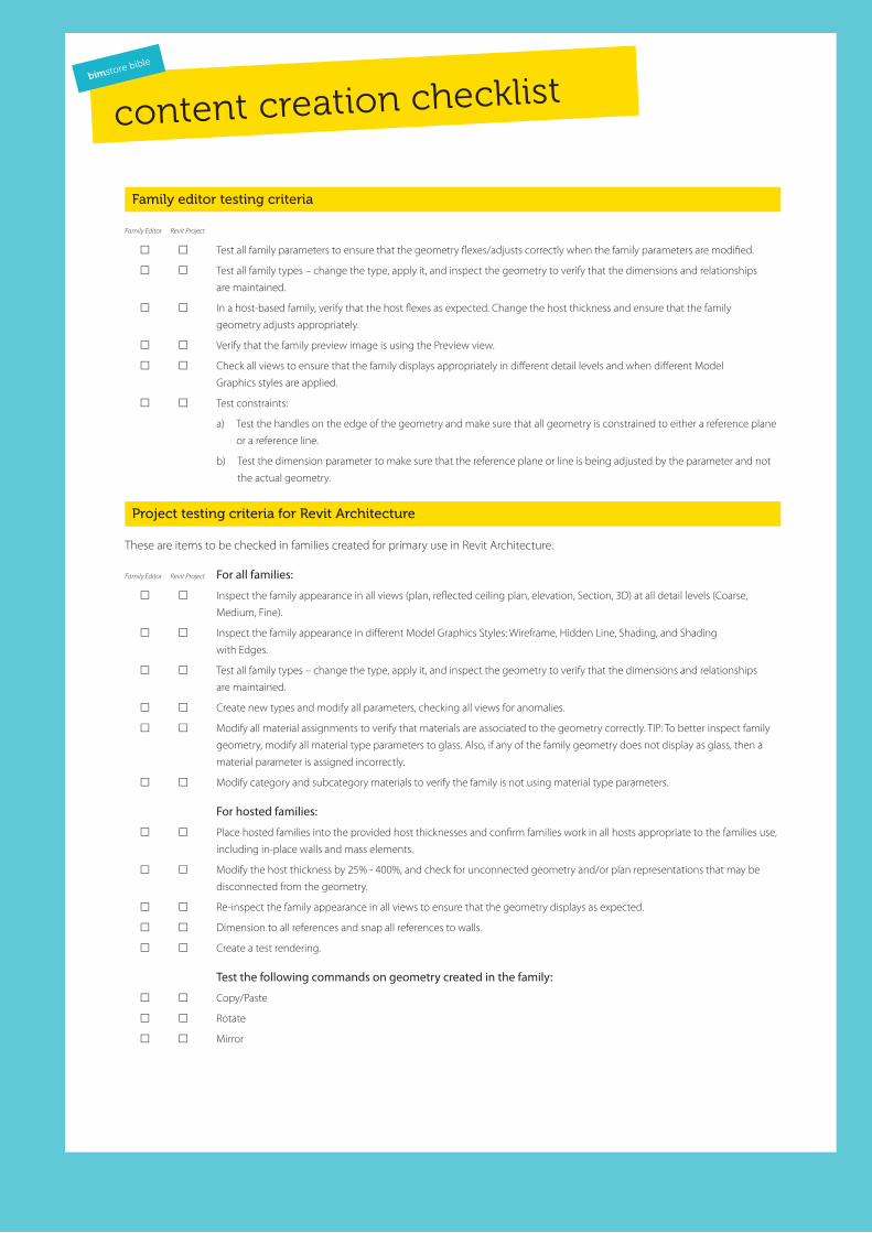
Family editor testing criteria
Family Editor Revit Project
Test all family parameters to ensure that the geometry flexes/adjusts correctly when the family parameters are modified.
Test all family types – change the type, apply it, and inspect the geometry to verify that the dimensions and relationships
are maintained.
In a host-based family, verify that the host flexes as expected. Change the host thickness and ensure that the family
geometry adjusts appropriately.
Verify that the family preview image is using the Preview view.
Check all views to ensure that the family displays appropriately in different detail levels and when different Model
Graphics styles are applied.
Test constraints:
a) Test the handles on the edge of the geometry and make sure that all geometry is constrained to either a reference plane
or a reference line.
b) Test the dimension parameter to make sure that the reference plane or line is being adjusted by the parameter and not
the actual geometry.
Project testing criteria for Revit Architecture
These are items to be checked in families created for primary use in Revit Architecture.
Family Editor Revit Project For all families:
Inspect the family appearance in all views (plan, reflected ceiling plan, elevation, Section, 3D) at all detail levels (Coarse,
Medium, Fine).
Inspect the family appearance in different Model Graphics Styles: Wireframe, Hidden Line, Shading, and Shading
with Edges.
Test all family types – change the type, apply it, and inspect the geometry to verify that the dimensions and relationships
are maintained.
Create new types and modify all parameters, checking all views for anomalies.
Modify all material assignments to verify that materials are associated to the geometry correctly. TIP: To better inspect family
geometry, modify all material type parameters to glass. Also, if any of the family geometry does not display as glass, then a
material parameter is assigned incorrectly.
Modify category and subcategory materials to verify the family is not using material type parameters.
For hosted families:
Place hosted families into the provided host thicknesses and confirm families work in all hosts appropriate to the families use,
including in-place walls and mass elements.
Modify the host thickness by 25% - 400%, and check for unconnected geometry and/or plan representations that may be
disconnected from the geometry.
Re-inspect the family appearance in all views to ensure that the geometry displays as expected.
Dimension to all references and snap all references to walls.
Create a test rendering.
Test the following commands on geometry created in the family:
Copy/Paste
Rotate
Mirror
Checklist
Template List
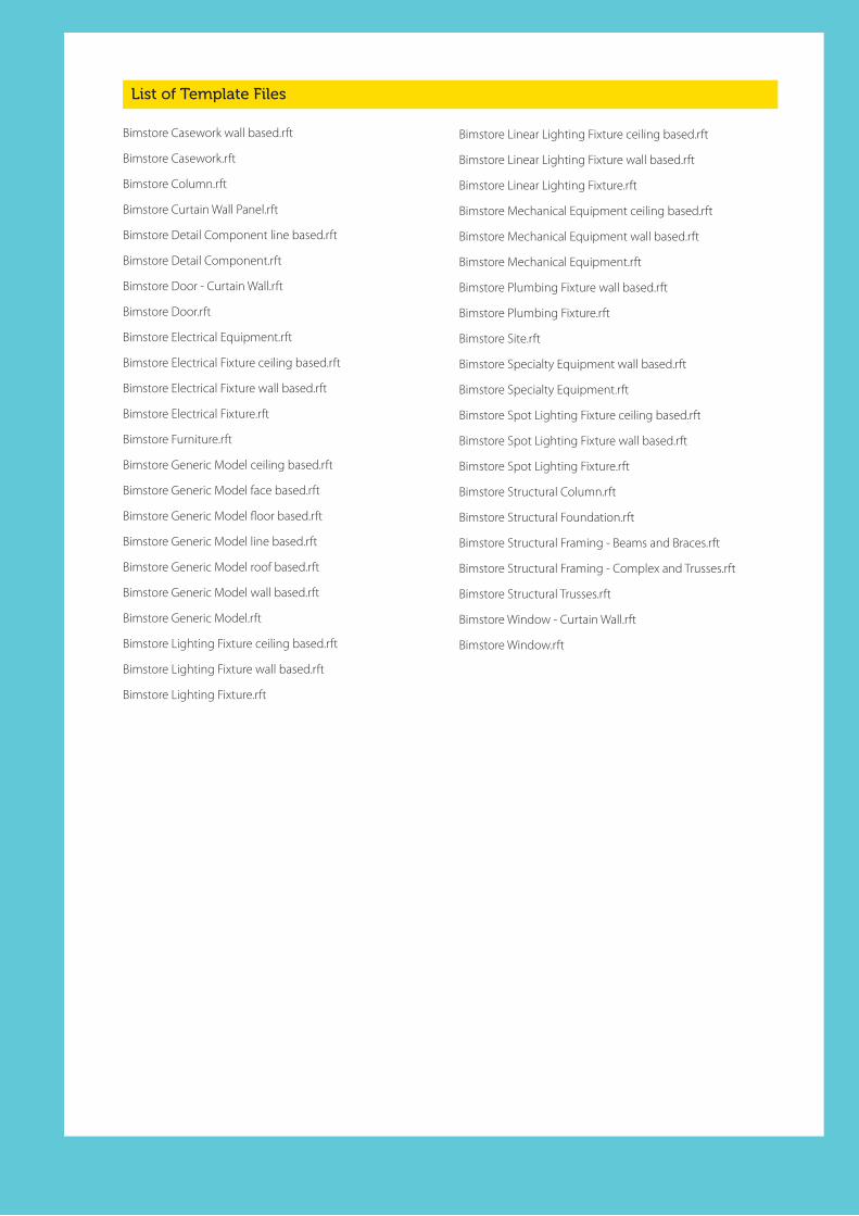
List of Template Files
Bimstore Casework wall based.rft
Bimstore Casework.rft
Bimstore Column.rft
Bimstore Curtain Wall Panel.rft
Bimstore Detail Component line based.rft
Bimstore Detail Component.rft
Bimstore Door - Curtain Wall.rft
Bimstore Door.rft
Bimstore Electrical Equipment.rft
Bimstore Electrical Fixture ceiling based.rft
Bimstore Electrical Fixture wall based.rft
Bimstore Electrical Fixture.rft
Bimstore Furniture.rft
Bimstore Generic Model ceiling based.rft
Bimstore Generic Model face based.rft
Bimstore Generic Model floor based.rft
Bimstore Generic Model line based.rft
Bimstore Generic Model roof based.rft
Bimstore Generic Model wall based.rft
Bimstore Generic Model.rft
Bimstore Lighting Fixture ceiling based.rft
Bimstore Lighting Fixture wall based.rft
Bimstore Lighting Fixture.rft
Bimstore Linear Lighting Fixture ceiling based.rft
Bimstore Linear Lighting Fixture wall based.rft
Bimstore Linear Lighting Fixture.rft
Bimstore Mechanical Equipment ceiling based.rft
Bimstore Mechanical Equipment wall based.rft
Bimstore Mechanical Equipment.rft
Bimstore Plumbing Fixture wall based.rft
Bimstore Plumbing Fixture.rft
Bimstore Site.rft
Bimstore Specialty Equipment wall based.rft
Bimstore Specialty Equipment.rft
Bimstore Spot Lighting Fixture ceiling based.rft
Bimstore Spot Lighting Fixture wall based.rft
Bimstore Spot Lighting Fixture.rft
Bimstore Structural Column.rft
Bimstore Structural Foundation.rft
Bimstore Structural Framing - Beams and Braces.rft
Bimstore Structural Framing - Complex and Trusses.rft
Bimstore Structural Trusses.rft
Bimstore Window - Curtain Wall.rft
Bimstore Window.rft
1. Introduction .................................................................................................. 3
2. Planning a model family ............................................................................. 4
2.1. Determining the template to use 4
2.2. Determine the family’s use 5
2.3. Level of detail 6
2.4. Element visibility 7
2.5. Nesting families 7
2.6. Family size 8
2.7 Areas to avoid for optimal performance 8
3. Content creation workflow ......................................................................... 9
3.1. Prototyping 9
4. Family Units ................................................................................................. 10
5. Family Naming ............................................................................................ 11
5.1. Family (component) naming 11
5.2. Type naming conventions 12
6. Category and subcategory standards and usage ................................ 13
7. bimstore parameter usage ....................................................................... 14
7.1. Parameter naming convention 15
7.2. Correct use of the bimstore parameters 16
7.3. Cobie parameters 16
17
7.4 Classification Parameters 18
7.4.1 NBS Create Parameters 18
7.4.2 Additional IFC Parameters 18
7.5. Assigning the Masterformat and Uniformat Classification 19
7.6 Assigning the Omniclass Classification in Revit 19
8. Material naming conventions .................................................................. 20
8.1. Material naming 20
8.2. Material ‘image’ naming 21
8.3 Custom Materials 21
9. Preview image standards .......................................................................... 22
9.1. How to create - detail component preview image 23
9.2. How to create a model component image ............................................ 24
10. Type catalogue standards and usage ..................................................... 25
10.1 Type Catalogue Standards ....................................................................... 25
11. Material application in model families ................................................... 26
11.1. Option 1 – Applying materials with the material parameter ............. 27
11.2. Option 2 – Apply materials to a family geometry by category and subcategory ......................................................................................... 27
11.3. Apply materials to family by category and subcategory .................... 27
12. Adding MEP connectors in families ........................................................ 28
12.1. Adding a connector ................................................................................... 28
12.2. Connector direction ................................................................................... 29
12.3. Primary Connector ..................................................................................... 29
12.4. Linking connector ...................................................................................... 30
13. General family testing guidelines ........................................................... 31
13.1. Family editor testing criteria .................................................................... 31
13.2. Project testing criteria for Revit Architecture ....................................... 32
13.3. Family specific testing guidelines ........................................................... 33
14. Distributing content .................................................................................. 34
Appendix 01: Documentation Templates ............................................................ 35
Content creation checklist ....................................................................................... 37
Template list ............................................................................................................... 40


North EastSpaceworksBenton Park RoadNewcastle upon TyneNE7 7LX
T.+44 (0)191 223 6600F. +44 (0)191 223 6610
Yorkshire1 Brewery PlaceBrewery WharfLeedsLS10 1NE
T. +44 (0)844 800 6660F. +44 (0)113 243 1396
North West80 Mosley StreetSt Peter’s SquareManchesterM2 3FX
T. +44 (0)844 800 6660F. +44 (0)161 236 2384
Humberside_space@TheStudio Geneva Way Leeds Road Hull HU7 0DG
T. +44 (0)844 800 6660F. +44 (0)113 243 1396
London175-185 Gray’s Inn Road London WCI 8UE
T. 0207 812 0581