Embed Size (px)
Citation preview
BWC EXCEL 1
48 VDC Battery Charging System
Owner’s Manual
Bergey Windpower Co. 2200 Industrial Blvd.
Norman, OK 73069 USA Telephone: (405) 364-4212
Fax: (405) 364-2078 E-mail: [email protected]
Web: www.bergey.com
EXCEL 1 Wind Turbine
Version 1.1 December 2012

1
BWC EXCEL 1 Wind Turbine 48V System
OWNER’S MANUAL
TableofContents1. Overview .................................................................................................................................................. 2 2. Cautions and Warnings ............................................................................................................................ 3 3. System Description .................................................................................................................................. 4 4. System Operation .................................................................................................................................... 6 5. Turbine Installation ................................................................................................................................... 8 6. Inspections and Maintenance ................................................................................................................ 14 7. Trouble-Shooting Problems ................................................................................................................... 16 8. Installation Planning ............................................................................................................................... 17 9. Specifications .......................................................................................................................................... 22 10. Basic Tower Requirements ................................................................................................................... 23 11. System Single Line Diagram ................................................................................................................. 26 12. Identification ......................................................................................................................................... 27 13. Warranty ................................................................................................................................................ 27 14. Registration Card .................................................................................................................................. 28 Appendix ..................................................................................................................................................... 29
How to Avoid the Most Common Mistakes When Installing an EXCEL 1 .............................. 29 MidNite TCB Turbine Control Box Installation Instructions MidNite Solar Classic Owner's Manual
TableofFiguresFigure 1: EXCEL 1 on a Tilt Tower .............................................................................................................. 2 Figure 2: Major Components of the EXCEL 1 Wind Turbine ....................................................................... 4 Figure 3: AutoFurl ........................................................................................................................................ 6 Figure 4: Tower Mounting for the EXCEL 1 ................................................................................................. 8 Figure 5: Turbine Mounting .......................................................................................................................... 9 Figure 6: Tail Fin Attachment ..................................................................................................................... 10 Figure 7: Tail Boom Attachment ................................................................................................................ 11 Figure 8: Blade and Spinner Fasteners ..................................................................................................... 12 Figure 9: Nut Tightening Order .................................................................................................................. 12 Figure 10: Tower Adapter Requirements .................................................................................................... 24 Figure 11: Top Tower Section ..................................................................................................................... 25 Figure 12: Single Line Diagram (Typical) .................................................................................................... 26
TableofTablesTable 1: Variation in wind speed and expected relative energy output with tower height ......................... 18 Table 2: Recommended Wire Sizes for the 48V EXCEL 1 ........................................................................ 20
2
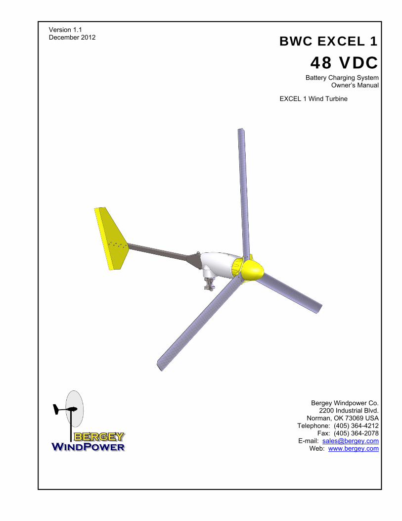
1. Overview The BWC EXCEL 1-48 wind turbine system is a state-of-the-art small generator designed to charge bat-teries and supply electrical loads in a 24 to 48 VDC power system. When used in conjunction with a suitable sine wave DC-AC inverter and a 48 VDC battery bank the EXCEL 1-48 can also be connected to the power grid. The EXCEL 1-48 turbine consists of a 1kW wind turbine, a MidNite Solar Turbine Control Box and the MidNite Solar Classic 250 charge controller. The EXCEL 1-48 wind turbine features superior low-wind-speed performance, very high system efficien-cy, and low noise. The BWC EXCEL 1-48 is offered with the optional guyed tubular Tilt Tower, which comes in heights from 60’ to 100’. The Tilt Tower is shown in Figure 1. For installation procedures on this tower, please refer to the “BWC EXCEL 1 Tilt Tower Installation Manual”. This manual is available on-line at http://www.bergey.com.
Figure 1: EXCEL 1 on a Tilt Tower

3
2. Cautions and Warnings This manual contains important information on the installation of your BWC EXCEL 1 wind turbine and charge controller. We strongly recommend that you read and follow the instructions contained in this manual. At several points in the manual items of special interest or significant impact are highlighted by one of the following notices.
DANGER: Hazard or unsafe practice that could cause personal injury or death.
WARNING: Hazard or unsafe practice which could cause product damage. NOTE: Significant point of interest.
4
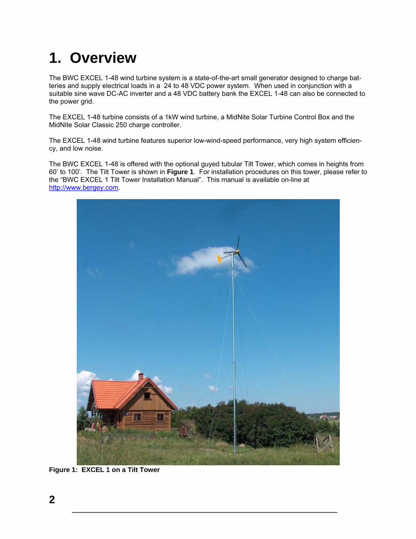
3. System Description EXCEL 1 Wind Turbine Components The major components of the EXCEL 1 wind turbine are shown in Figure 2. A. Blades / Rotor System The rotor system consists of three fiberglass blades. Acting like aircraft wings, the blades convert the energy of the wind into rotational forces that drive an alternator. The airfoil on the EXCEL 1 is the new SH3045 developed specifically for the EXCEL 1 by Bergey WindPower. The fiberglass blades are excep-tionally strong because they are densely packed with glass reinforcing fibers that run the full length of the blade.
Figure 2: Major Components of the EXCEL 1 Wind Turbine B. Alternator The alternator rotates from torque generated by the rotor blades to produce electricity. The alternator utilizes permanent magnets and has an inverted configuration in that the outside housing (magnet can) rotates, while the internal stator windings and central shaft are stationary. The alternator was specially designed for the EXCEL 1 and produces power at low RPM’s, eliminating the need for a gearbox. The output from the alternator is three-phase alternating current (AC), and is rectified to direct current (DC) to charge the battery bank. Since it uses permanent magnets, the alternator is generating voltage whenever the rotor is turning.
Danger The output wiring of the BWC EXCEL 1-48 presents a shock hazard whenever the rotor is turning. Caution must be exercised at all times to avoid electrical shock.
Alternator
PowerheadTail Fin
Tower Mount/Adapter Spinner
Blades
Nacelle

5
C. Nacelle The nacelle is the fiberglass housing around the main body of the machine. It contains the main structur-al “backbone” of the turbine (called the mainframe), the slip-ring assembly, the yaw bearings, and the tower mount. The yaw bearings allow the wind turbine to freely pivot around the top of the tower so that the rotor will face into the wind. The slip-ring assembly is the electrical connection between the moving (as it orients with the wind direc-tion) wind turbine and the fixed tower wiring. The slip-rings and yaw bearings are located just above the tower mount. The tower mount attaches the EXCEL 1 turbine to the top of the tower. D. Tail Assembly and AutoFurl Operation The tail assembly, composed of a tail boom and the tail fin, keeps the powerhead (and, therefore, the ro-tor) aligned into the wind at wind speeds below approximately 12.5 m/s (28 mph). At about 12.5 m/s the AutoFurl mechanism (see Figure 3) turns the rotor away from the wind to limit its speed. The tail ap-pears to fold, but in reality the tail stays stationary, as the powerhead turns sideways to the wind. The rotor does not, however, furl completely sideways. This allows the turbine to continue to produce power in high winds. When the high winds subside the AutoFurl system automatically restores the turbine to the normal straight position. E. MidNite Solar Turbine Control Box The MidNite Solar Turbine Control Box (TCB) is used to convert the turbine’s AC power to DC power. It also can be used to temporarily short the turbine during maintenance of the turbine system. The owner’s manual for the TCB is included in the Appendix. F. MidNite Solar Classic 250 The MidNite Solar Classic 250 charge controller is used to control the charging of batteries. The owner’s manual for the Classic is included in the Appendix.
6
4. System Operation A. Normal Operation The rotor of the BWC EXCEL 1 should begin to rotate when the wind speed reaches approximately 3 m/s (7 mph). Battery charging should commence shortly after the rotor spins up to speed. Once turning, the rotor will continue to turn in lower wind speeds, down to approximately 2.5 m/s (6 mph).
Note All operational wind speeds given assume steady winds, sea-level altitude and moderate temperatures. Hot weather, high altitude, turbulence, and gusting winds will reduce system per-formance.
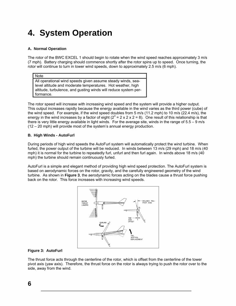
The rotor speed will increase with increasing wind speed and the system will provide a higher output. This output increases rapidly because the energy available in the wind varies as the third power (cube) of the wind speed. For example, if the wind speed doubles from 5 m/s (11.2 mph) to 10 m/s (22.4 m/s), the energy in the wind increases by a factor of eight (23 = 2 x 2 x 2 = 8). One result of this relationship is that there is very little energy available in light winds. For the average site, winds in the range of 5.5 – 9 m/s (12 – 20 mph) will provide most of the system’s annual energy production. B. High Winds - AutoFurl During periods of high wind speeds the AutoFurl system will automatically protect the wind turbine. When furled, the power output of the turbine will be reduced. In winds between 13 m/s (29 mph) and 18 m/s (40 mph) it is normal for the turbine to repeatedly furl, unfurl and then furl again. In winds above 18 m/s (40 mph) the turbine should remain continuously furled. AutoFurl is a simple and elegant method of providing high wind speed protection. The AutoFurl system is based on aerodynamic forces on the rotor, gravity, and the carefully engineered geometry of the wind turbine. As shown in Figure 3, the aerodynamic forces acting on the blades cause a thrust force pushing back on the rotor. This force increases with increasing wind speeds.
Figure 3: AutoFurl The thrust force acts through the centerline of the rotor, which is offset from the centerline of the tower pivot axis (yaw axis). Therefore, the thrust force on the rotor is always trying to push the rotor over to the side, away from the wind.

7
But the rotor is kept facing into the wind at speeds up to ~ 12.5 m/s (28 mph) by the wind turbine’s tail assembly. The tail, in turn, is kept straight by its own weight because its pivot at the back of the nacelle is inclined. So the weight of the tail holds it against a rubber bumper and the tail holds the rotor into the wind. The geometries in the systems are carefully balanced so that at ~ 12.5 m/s (28 mph) the rotor force acting on the yaw-offset is large enough to overcome the preset force holding the tail straight. At this point the rotor will start turning away from the wind or furling. The tail stays aligned with the wind direction. The speed of furling depends on the severity of the wind gusts and whether the wind turbine stays furled de-pends on the wind speed. As the wind turbine furls the geometry of the tail pivot causes the tail to lift slightly. When the high winds subside the weight of the tail assembly returns the whole turbine to the straight position. The AutoFurl system works whether the turbine is loaded or unloaded. The AutoFurl system is completely passive, so it is very reliable and since there are no wear points, like in a mechanical brake system, it is very robust. AutoFurl was used in the very first wind system produced by Bergey Windpower in 1980 and in every unit produced since. AutoFurl is an important element of our success. There is one situation in the field, however, that we have found can disrupt the operation of AutoFurl. If the wind turbine is installed on a sharp hill or next to a cliff so that the wind can come up through the rotor on an incline (e.g., from below; as opposed to horizontally) we know that this will affect furling and can produce higher peak outputs. We strongly recommend avoiding this situation.
Warning Do not install the EXCEL 1 wind turbine near cliffs or precipices or on sharp hills such that the wind does not travel hori-zontally through the rotor.
8
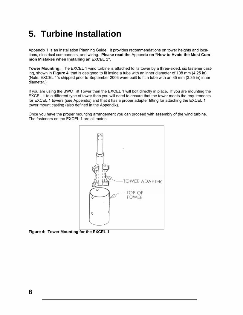
5. Turbine Installation Appendix 1 is an Installation Planning Guide. It provides recommendations on tower heights and loca-tions, electrical components, and wiring. Please read the Appendix on “How to Avoid the Most Com-mon Mistakes when Installing an EXCEL 1”. Tower Mounting: The EXCEL 1 wind turbine is attached to its tower by a three-sided, six fastener cast-ing, shown in Figure 4, that is designed to fit inside a tube with an inner diameter of 108 mm (4.25 in). (Note: EXCEL 1’s shipped prior to September 2003 were built to fit a tube with an 85 mm (3.35 in) inner diameter.) If you are using the BWC Tilt Tower then the EXCEL 1 will bolt directly in place. If you are mounting the EXCEL 1 to a different type of tower then you will need to ensure that the tower meets the requirements for EXCEL 1 towers (see Appendix) and that it has a proper adapter fitting for attaching the EXCEL 1 tower mount casting (also defined in the Appendix). Once you have the proper mounting arrangement you can proceed with assembly of the wind turbine. The fasteners on the EXCEL 1 are all metric.
Figure 4: Tower Mounting for the EXCEL 1
9
Tilt-up Type Towers: If you have a tilting tower, such as the BWC Tilt Tower, the following proce-dure is recommended: Tools Required:
17 mm box end wrench 17 mm socket and 300mm (12”) ratchet drive 8 mm socket or wrench 4 mm Allen wrench Torque wrench (at least 50 ft-lb) Pliers Crimpers for wiring terminals (U-shaped crimp preferred over straight crimp) Thread locking compound (like Loctite 242) Tape measure, 12 ft.
Procedure: Step 1: With the tower tilted down, place the powerhead of the wind turbine near the top end of the tower. The tower wiring is connected to the EXCEL 1 wind turbine at the slip-ring using three M6 screws and ring terminals crimped to the three conductors. BWC does not supply these ring terminals. Cut the outer insulation on the wire back about 60 mm (2.5 in). Strip the insulation off the outer 12 mm (1/2 in) of each conductor and crimp on the appropriate ring terminals. Attach the power conductors to the slip-ring as-sembly with the screws provided and torque to 60 in-lbs (5 ft-lbs).
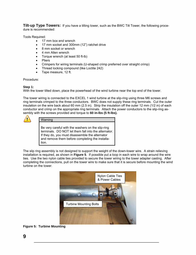
The slip ring assembly is not designed to support the weight of the down-tower wire. A strain relieving installation is required, as shown in Figure 5. If possible put a loop in each wire to wrap around the wire ties. Use the two nylon cable ties provided to secure the tower wiring to the tower adapter casting. After completing the connections, pull on the tower wire to make sure that it is secure before mounting the wind turbine on the tower.
Figure 5: Turbine Mounting
Warning Be very careful with the washers on the slip-ring terminals. DO NOT let them fall into the alternator. If they do, you must disassemble the alternator and remove them before completing the installa-tion.
Turbine Mounting Bolts
Nylon Cable Ties & Power Cables
10
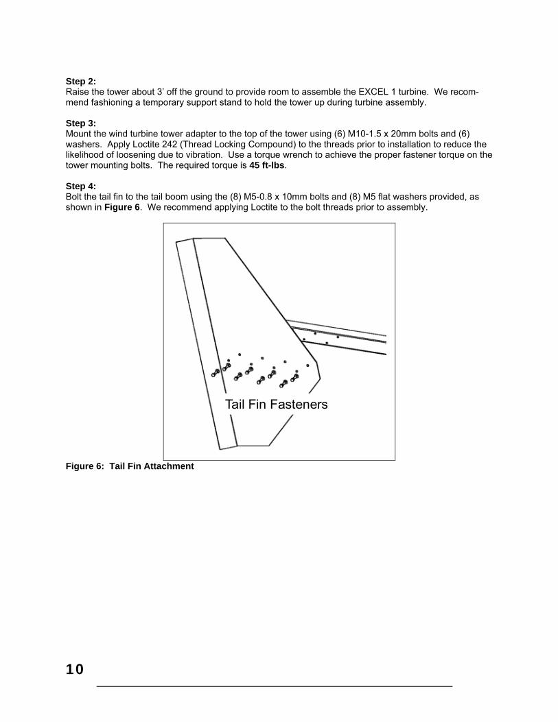
Step 2: Raise the tower about 3’ off the ground to provide room to assemble the EXCEL 1 turbine. We recom-mend fashioning a temporary support stand to hold the tower up during turbine assembly. Step 3: Mount the wind turbine tower adapter to the top of the tower using (6) M10-1.5 x 20mm bolts and (6) washers. Apply Loctite 242 (Thread Locking Compound) to the threads prior to installation to reduce the likelihood of loosening due to vibration. Use a torque wrench to achieve the proper fastener torque on the tower mounting bolts. The required torque is 45 ft-lbs. Step 4: Bolt the tail fin to the tail boom using the (8) M5-0.8 x 10mm bolts and (8) M5 flat washers provided, as shown in Figure 6. We recommend applying Loctite to the bolt threads prior to assembly.
Tail Fin Fasteners
Figure 6: Tail Fin Attachment
11
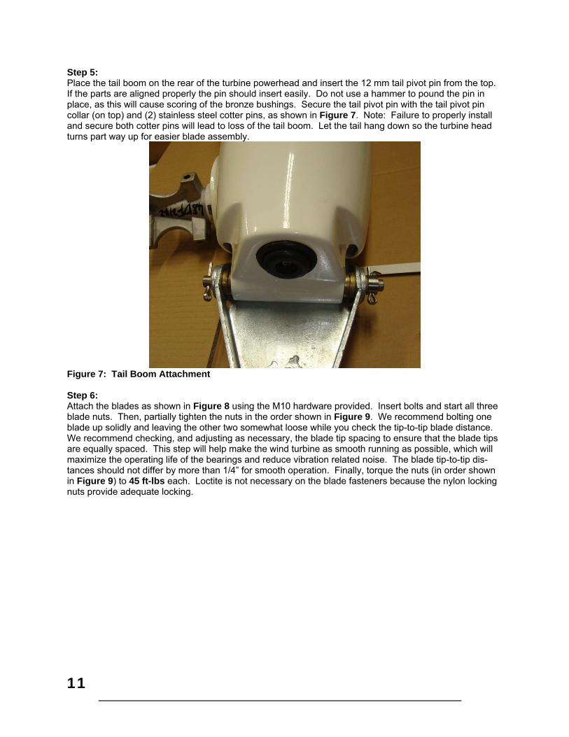
Step 5: Place the tail boom on the rear of the turbine powerhead and insert the 12 mm tail pivot pin from the top. If the parts are aligned properly the pin should insert easily. Do not use a hammer to pound the pin in place, as this will cause scoring of the bronze bushings. Secure the tail pivot pin with the tail pivot pin collar (on top) and (2) stainless steel cotter pins, as shown in Figure 7. Note: Failure to properly install and secure both cotter pins will lead to loss of the tail boom. Let the tail hang down so the turbine head turns part way up for easier blade assembly.
Figure 7: Tail Boom Attachment
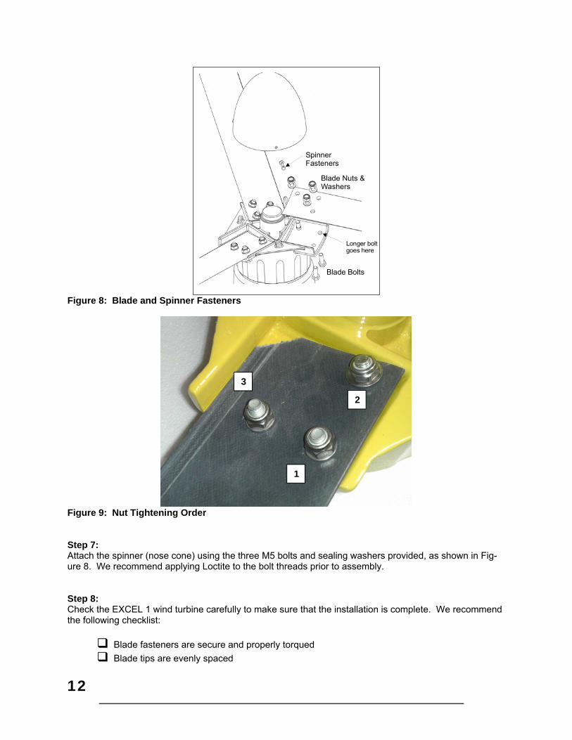
Step 6: Attach the blades as shown in Figure 8 using the M10 hardware provided. Insert bolts and start all three blade nuts. Then, partially tighten the nuts in the order shown in Figure 9. We recommend bolting one blade up solidly and leaving the other two somewhat loose while you check the tip-to-tip blade distance. We recommend checking, and adjusting as necessary, the blade tip spacing to ensure that the blade tips are equally spaced. This step will help make the wind turbine as smooth running as possible, which will maximize the operating life of the bearings and reduce vibration related noise. The blade tip-to-tip dis-tances should not differ by more than 1/4” for smooth operation. Finally, torque the nuts (in order shown in Figure 9) to 45 ft-lbs each. Loctite is not necessary on the blade fasteners because the nylon locking nuts provide adequate locking.
12
Longer boltgoes here
Blade Nuts &Washers
Blade Bolts
SpinnerFasteners
Figure 8: Blade and Spinner Fasteners
Figure 9: Nut Tightening Order Step 7: Attach the spinner (nose cone) using the three M5 bolts and sealing washers provided, as shown in Fig-ure 8. We recommend applying Loctite to the bolt threads prior to assembly.
Step 8: Check the EXCEL 1 wind turbine carefully to make sure that the installation is complete. We recommend the following checklist:
Blade fasteners are secure and properly torqued
Blade tips are evenly spaced
2
3
1

13
Spinner is secure
Tail fin is secure
Tail pivot pin is locked in place with both cotter pins.
Tower adapter bolts are secure Step 10: Dynamically brake the EXCEL 1’s alternator by using the shorting function of the turbine control box. Step 11: Raise the tower following the procedures outlined by the tower supplier. Please make safety your top priority. Non-tilting Towers: On a non-tilting tower, such as a fixed guyed tower or a self-supporting pole type tower, there are two general approaches that can be used: 1) assemble the tower and turbine to-gether on the ground and then use a light-duty crane to set the tower in place, or 2) erect the tower and then lift the wind turbine to the top with either a light-duty crane or a gin-pole. A gin-pole, in this case, is a tower assembly tool that attaches to the tower and provides an arm with a pulley so that parts can be hoisted above the top of the tower. Gin-poles are used by professional tower erectors and we do not recommend their use by non-professionals. We know of at least one homeowner who died while improperly using a gin-pole to install a small wind turbine (though not a Bergey turbine). Wherever possible we strongly recommend assembling the tower and turbine on the ground. In this case please follow the general procedure for turbine assembly provided in the preceding section. When raising the tower you must lift the tower, not the EXCEL 1 wind turbine. The EXCEL 1 cannot support the weight of the tower. For customers installing a BWC EXCEL 1 on an existing fixed tower we recommend that you use a crane to lower the tower so that you can attach the turbine on the ground. Alternatively, we recommend you use a bucket-truck, like the type used by utility linemen. Check with local sign companies because they often offer bucket-truck services at reasonable hourly rates. If neither of these approaches is possible then we recommend that you engage the services of professional wind turbine or tower erectors to install your wind turbine.
14
6. Inspections and Maintenance The BWC EXCEL 1 installation should be inspected after 30 days and then again 180 days after installa-tion. Following these two inspections the installation should be inspected every two years and after any particularly severe weather. In corrosive marine environments more frequent inspections are recom-mended. Inspections should be done on days when the wind is below 7 m/s (16 mph). Check List for Inspections 1) Inspect each of the anchor points. Ensure that all hardware is secure and the guy wires are properly
tensioned. Check to ensure that no cable & guy wire strands are broken. 2) Use the turbine control box to stop the alternator. Once the rotor is stopped, climb or lower the tower.
Always use proper safety belts and lanyards when climbing.
3) Inspect the blades for:
a) Condition of the leading and trailing edges, particularly out near the tip. b) Tip damage. c) Cracks outboard of the hub pad, in the blade pultrusion itself. Cracks in the molded hub pad are
normal after a few weeks of operation and will not affect the strength or reliability of the blade. 4) Remove the spinner. Check the torque on the blade nuts; the torque value is 45 ft-lbs. Check the
front bearing cover for seal integrity and grease loss. Check the alternator bearings for lack of play, a tiny amount of play is acceptable and normal, if it appears excessive, pop the front bearing cover off. This will expose the bearing adjustment nut. Remove the cotter pin and tighten the nut to just snug. DO NOT USE A WRENCH, if the cotter pin will go through one of the two holes in the alternator shaft then push it through, if not BACK THE NUT OFF (CCW) until a cotter pin will go through. Replace the front bearing cover. Reattach the spinner and check that it is secure.
5) Inspect the mainframe for cracks. 6) Inspect the slip rings & brush assemblies for cleanliness and signs of heating. Clean as necessary. 7) Check the screws holding the nacelle and tail fin rubber bumpers in place. 8) Check the cotter pins on the tail pivot pin. 9) Check for cracks or loose hardware on the tail boom, bushings, and fin. 10) Check the torque on the tower mounting bolts; the recommended value is 45 ft-lbs. 11) While descending the tower or before raising it, inspect the following:
a) Check that the tower wiring is properly secure. b) Check all tower fasteners. c) Look for any cracks in the tower structure. d) Check the condition of the guy wire attachments. e) Use temporary guys rope for gin pole support.
12) Check the connection on all ground rods and hardware. 13) Inspect the surge arrestor(s) if used. Replace if there are signs of damage. 14) Inspect the wire run, particularly all electrical connections and disconnect switches. 15) Check condition of all wiring connections into and out of the charge controller. 16) Restart the turbine. 17) Listen to the sound of the machine as it speeds up. No mechanical sounds, such as a "clunking" or
"banging," should be heard. Also watch for any new or significant vibration. Some “growling” from the alternator is normal. The turbine operation should be smooth.
Danger Only qualified personnel with proper safety equipment should climb the tower. Never climb the tower when the rotor is turning.

15
Preventive Maintenance We recommend that the bearings be re-packed (re-greased) every 8-12 years. There are four tapered roller bearings, two for the alternator and two for the tower adapter. There are two bearing seals and we recommend that these seals be replaced when the bearings are re-packed. The strength of the blades, particularly at the root (inner) end, may degrade over time due to flexure and UV degradation of the fiberglass material. The symptom of degradation is a reduction in blade stiffness fore-and-aft. The blades have to become very flexible in the fore-aft direction before there is any risk of tower strikes during severe weather. We recommend that you check blade stiffness about every 10 years and replace the blades if they become extremely flexible. In some installation environments, the blades will develop fiberglass “fuzz”. If this is found, the blades should be lightly and evenly sanded with fine grit sand paper and painted to provide UV protection.

16
7. Trouble-Shooting Problems The following guide can be used to pinpoint the cause of operational problems with the BWC EXCEL 1 wind turbine and the charge controller. For problems or symptoms not found in the following listing, please contact the Service Department at Bergey Windpower Co. at: Tel: (405) 364-4212 Fax: (405) 364-2078 e-mail: [email protected] Problem Cause(s) Diagnosis Remedy
Battery voltage gets too high.
Charge controller reg-ulating voltage set too high
Excessive battery gassing. Use voltmeter to check bat-tery cell voltages or hydrome-ter to check the specific gravi-ty – compare to battery manufacturers recommenda-tions.
Refer to the MidNite So-lar Classic Owner’s Manual to adjust the battery regulation volt-age.
Batteries do not reach full state of
charge.
Charge controller reg-ulating voltage set too low.
Use hydrometer to check the specific gravity of the battery cells. Compare with battery manufacturer’s recommenda-tion.
Refer to the MidNite So-lar Classic Owner’s Manual to adjust the battery regulation volt-age.
Loads are too large. Remove largest load. If bat-tery bank reaches higher state of charge, then the sys-tem is overloaded.
Consult with BWC about possible remedies.
Rotor turns, but the system doesn’t
charge the batteries.
Blown Turbine discon-nect breaker
Check voltage across breaker with turbine spinning, should be near zero volts AC.
Replace breaker (if used).
Open breaker in tur-bine control box.
Check breaker position Check all wiring, correct if necessary. Reset breaker.
Turbine control box rectifier failure, possi-ble damaged stator winding
Check voltage from the tur-bine.
Replace rectifier assem-bly, or stator
Rotor is unbalanced, causing the turbine
to move slightly back and forth as it spins.
Blade tips not evenly spaced.
Check tip-to-tip distances with a tape measure. They should be within 6.5 mm (¼”).
Loosening one blade at a time, adjust the tip spacing to bring distanc-es within specifications.
Ice build-up on blades. Visual inspection. Severe icing is very obvious.
Take no action. Do not stand under machine. The ice will be shed when there is sufficient sun and wind.
Wind is higher than 16 mph, but rotor will
not turn, or turns slowly
Short in power leads. Check connections first. Iso-late power leads. Use VOM to check for short circuit.
Repair short circuit.
Short in alternator Replace alternator
Charge controller fail-ure.
Disconnect turbine from charge controller. Turbine should start.
Contact MidNite Solar for troubleshooting.

17
8. Installation Planning Installation Planning The location and height of the tower for the BWC EXCEL 1 wind system will be important factors in de-termining the overall performance of the system. Average wind speed is influenced by many things and may vary considerably within a relatively small region, particularly in complex terrain. Site and tower choice, however, are often limited by such factors as zoning restrictions, property size, proximity to neigh-bors, customer preferences, and wiring costs. All of these factors should be taken into consideration in choosing the best tower site and height. A. Legal Restrictions and Good Neighbor Relations One of the first steps in planning an installation is to determine the legal status of the proposed wind tur-bine installation in the community in which it will be installed. In most cities and some counties an instal-lation will be subject to zoning laws and building codes. Some neighborhoods have protective covenants that limit the types of home improvements. In areas requiring permits the installation must be planned weeks to months in advance to allow time for applications to be processed and, if necessary, hearings to be held. The quickest way to determine the local codes and requirements is to call or visit the office of the building inspector. Few cities have specific regulations dealing with wind turbines, but most will have height re-strictions, building code requirements, and a formal process for obtaining a building permit. The most common problem encountered in the United States is a height restriction of 35’, particularly in residentially zoned areas. A 30’ tower meets the 35 ft restriction, but it does so at some loss in performance. If you need or want to go higher than the zoning height restriction you must apply for a variance. A variance is essentially per-mission to break a rule and it is granted following a public hearing before a Planning Board. Obtaining a variance is a major undertaking, costing $200-5,000 and taking several months, so it is important to es-tablish whether it will be necessary as soon as possible. Bergey Windpower Co. has experience in working with customers and BWC dealers in variance hearings and we offer advice and assistance to those who request it. Generally, in order to obtain a building permit you will be required to submit a plot plan and fill out an ap-plication. A plot plan is a map, drawn to scale, of your property showing the boundaries, dwelling(s) and other structures, major topographic features, easements, and, most importantly, the location and height of the proposed wind turbine tower. Often you will be required to submit plans for the tower and information on the wind turbine. In some cases you will also be required to submit a structural analysis of the tower to show that it is in compliance with the building code. Sometimes a registered Professional Engineer (PE) must sign this analysis and occasionally the PE must be licensed in the State where the unit will be installed. Bergey Windpower Co. has engineering analyses, PE-Certified, for most towers it offers and copies of these analyses are available to our customers. Noise data is occasionally required and will is available for the EXCEL 1 from Bergey Windpower Co in the “Technical” section of our website. If your property size is several acres or more than the turbine will likely be so far from the nearest neigh-bor’s house that they will not be bothered. It is, none the less, strongly recommended that you contact your nearest neighbors well in advance of any construction to let them know that you are installing a wind turbine. This is doubly good advice if your property size is less than several acres or you have to obtain a variance for a building permit. Good neighbor relations boil down to treating your neighbors the same way you would like to be treated and showing respect for their views. An example of what not to do is to

18
put the turbine on your property line so that it is closer to a neighbor’s house than to your own and not give those neighbors any advance notice of your intentions. In general, we do not recommend that a BWC EXCEL 1 be installed on property of less than one acre in size. We say this because the impact of a wind turbine on the neighbors in such a “tight” area is signifi-cant and the potential for disputes is too great. If you have questions about procedures, requirements, or tactics, please contact us. Since so few wind systems have been installed and communities are generally unfamiliar with them, you may face some obstacles in gaining permission to install a unit. We appreciate the pioneering spirit and resolve demon-strated by our customers and we stand ready to help out in any way that we can. B. Towers The smooth flow of the wind over the land is interrupted by obstructions and topographical variations. These interruptions bring about two important phenomena: wind shear and turbulence. Wind shear describes the fact that close to the ground the wind is slowed down by friction and the influence of obsta-cles. Thus, wind speed is low close to the ground and increases with increasing height above the ground. Wind shear is more pronounced over rough terrain and less pronounced over smooth terrain. Turbulence is essentially rough air caused by the wind passing over obstructions such as trees, buildings, or terrain features. Turbulent air reduces energy output and puts greater strain on the wind turbine. The effects of both wind shear and turbulence diminish with height and can be largely overcome simply by putting the machine sufficiently high above the ground. Taller towers usually will provide better eco-nomics because the power in the wind increases as the cube of the wind velocity (P = V3; e.g., a 26% increase in wind speed doubles the energy output). A small increase in average wind speed will result in a large increase in long-term energy output. Table 2 shows the influence that tower height can have on annual energy output for the BWC EXCEL 1 wind turbine under typical DOE Class 2 inland site conditions with a shear exponent of 0.20. Wind speed may increase more radically with tower height in hilly or wooded areas. In flat open areas, power produc-tion will increase less significantly with tower height. The BWC EXCEL 1 wind turbine must be placed on a tower that is tall enough to give the rotor proper exposure to the wind. Putting a wind turbine on a tower that is too short is like installing a solar system in the shade. As a “rule-of-thumb” the BWC EXCEL 1 should be 9 m (30 ft) above obstacles within 100 m (320 ft), particularly in the prevailing wind direction. So, the minimum recommended tower height is 18m (60 ft.). Table 1: Variation in wind speed and expected relative energy output with tower height
Tower Height Ft - (meters)
Average Wind Speed (m/s)
Relative Energy Production
30 (9) 4.8 100%
40 (13) 5.2 121%
60 (18) 5.6 147%
80 (24) 5.9 165%
100 (30) 6.2 186%

19
We do not recommend mounting the BWC EXCEL 1 on any home or any buildings. Our concerns are: 1. The forces on the turbine and mounting system are substantial and homes are not designed
structurally for them. 2. The air flow around and over a home or building is complex and can cause considerable turbu-
lence. 3. The wind turbine will cause vibrations that will be amplified through the home’s structure.
BWC offers a guyed-tubular tilt-up tower, the Tilt Tower, for the EXCEL 1 in heights form 18m (60ft) to 30m (100ft). The Tilt Tower is cost-effective and is designed to be installable by non-experts. The instal-lation of these towers is covered in the BWC EXCEL 1 Tilt Tower Installation Manual. Contact BWC for other tower options, including self-supporting towers that do not require guy wires. Customers can also supply their own towers. These towers have to meet certain criteria for strength and blade clearance (see Appendix), and a mounting adapter for the EXCEL 1 wind turbine will need to be designed and fabricated. Customer supplied towers are not covered by the BWC warranty and any dam-age to the EXCEL 1 wind turbine resulting from a customer supplied tower is excluded from the turbine warranty coverage. C. Location The size and layout of the installation site may limit the tower location, height, or type. More often than not, however, there are several potential sites. In choosing the best one, the following factors should be considered: 1. The proximity of the proposed site to dwellings. As noted before, it is a good idea for you to consult with neighbors about the installation before proceed-ing. The rotor system and alternator do produce a certain amount of sound. This is a low-level whirring sound that usually cannot be heard indoors. From a noise standpoint, the further the wind turbine is from a house the better. In general, we recommend that the turbine be installed at least 60’ from the house. Most often the tower is installed 60’ – 160’ from the owner’s house. Never choose a site that is closer to a neighbor’s home than to your own. 2. The local elevation at the tower site. Since system performance improves with increased wind turbine elevation it is sometimes best to site the tower on a hill or ridge to gain extra height. If, as is often the case however, the hill or ridge is a consid-erable distance (more than 330’) from the house the additional wiring costs may more than offset the per-formance gain to be realized. It is often less expensive to avoid the hill and simply choose a taller tower installed closer to the house. 3. The length of the wire run. While it is possible to install wire runs (the wiring between the wind turbine and the wind turbine electron-ics) of 650’ or more, the costs for long wire runs, particularly if they are buried, can be prohibitive. The longer the wire run, the larger and more expensive the wire that is required to conduct the electricity with acceptable losses. As a general rule, wire runs over 330’) if buried or 650’ if installed overhead should be avoided because of their high costs. 4. General convenience. Often the most compelling consideration for locating the wind turbine tower is the space where it will not interfere with vehicle traffic, fence lines, crops, gardens, septic system lateral lines, power poles, etc. Since the wind turbine installation is semi-permanent, your future plans for the property should also be
20
taken into consideration. When using a Tilt Tower you should consider the extra space needed for the tower when it is tilted down. 5. Safety The BWC EXCEL 1 should never be installed close to a power line. We recommend that the tower be at least 1 ½ times the height of the tower from any power line including any overhead service line bringing power to your home.
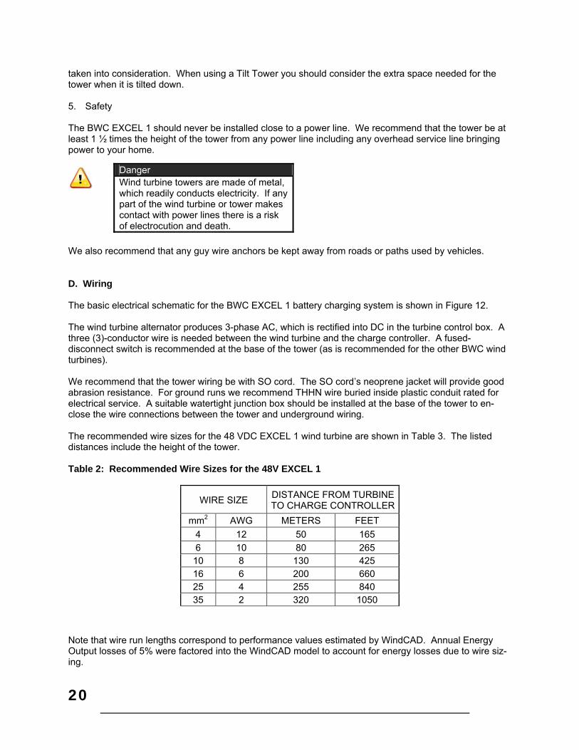
We also recommend that any guy wire anchors be kept away from roads or paths used by vehicles. D. Wiring The basic electrical schematic for the BWC EXCEL 1 battery charging system is shown in Figure 12. The wind turbine alternator produces 3-phase AC, which is rectified into DC in the turbine control box. A three (3)-conductor wire is needed between the wind turbine and the charge controller. A fused-disconnect switch is recommended at the base of the tower (as is recommended for the other BWC wind turbines). We recommend that the tower wiring be with SO cord. The SO cord’s neoprene jacket will provide good abrasion resistance. For ground runs we recommend THHN wire buried inside plastic conduit rated for electrical service. A suitable watertight junction box should be installed at the base of the tower to en-close the wire connections between the tower and underground wiring. The recommended wire sizes for the 48 VDC EXCEL 1 wind turbine are shown in Table 3. The listed distances include the height of the tower. Table 2: Recommended Wire Sizes for the 48V EXCEL 1
WIRE SIZE DISTANCE FROM TURBINE TO CHARGE CONTROLLER
mm2 AWG METERS FEET
4 12 50 165
6 10 80 265 10 8 130 425 16 6 200 660 25 4 255 840 35 2 320 1050
Note that wire run lengths correspond to performance values estimated by WindCAD. Annual Energy Output losses of 5% were factored into the WindCAD model to account for energy losses due to wire siz-ing.
Danger Wind turbine towers are made of metal, which readily conducts electricity. If any part of the wind turbine or tower makes contact with power lines there is a risk of electrocution and death.

21
Before assembling the wind turbine the tower wiring must be in place, though not necessarily permanent-ly affixed. We recommend that you leave at least 30 cm (12 in) of free wire at the top of the tower for making the electrical connections to the wind turbine. E. Other System Components A complete remote power system will include other electrical components such as a battery bank (re-quired), a solar array (optional), a dump load (optional), and an inverter (optional). The wind turbine and the other equipment are electrically connected to a “DC-bus” architecture, as shown in Figure 12. The DC-bus architecture is robust and very flexible, allowing a variety of options for multiple and differing components. The unifying feature is that all of these components are electrically connected to the posi-tive (+) and negative (-) DC bus, so they all experience the same DC voltage. The DC voltage of the sys-tem is largely determined by the state of charge of the battery bank and to a lesser, but still significant, extent by the charging or discharging rates (the rate at which DC power is being created or consumed). Charging components, such as wind turbines, solar arrays, and inverter/chargers (powered by a back-up generator or the power grid), can be added to a DC-bus system with separate charge regulators and these regulators can operate completely autonomously (e.g., they do not need to communicate with each other or be coordinated using a central system controller). The separate charge regulators, whether there is just one or if there are a dozen, will respond to the DC-bus voltage and control their generators charg-ing current. When putting together or adding to a DC-bus remote power system there are a few pitfalls to avoid if pos-sible:
Battery banks that are too small, so that battery voltage swings too much with high charging or discharging currents.
Multiple charge regulators set to the same voltage, so that there is one big step in charging cur-rent rather than several smaller ones.
Setting high voltage regulation points too low so that the batteries don’t get fully charged Setting the low voltage disconnect (typically part of the inverter) too high so that the battery bank
capacity is underutilized. If using both solar and wind turbine power, set the wind charger voltage a little higher than the so-
lar charge voltage to keep load on the turbine whenever possible. This helps keep the turbine noise level lower.

22
9. Specifications EXCEL 1 TURBINE:
Metric Imperial ROTOR DIAMETER 2.5 m 8.2 ft. OVERALL LENGTH 2.1 m 6.9 ft. TURBINE WEIGHT 34 kg 75 lbs. TURBINE THRUST 890 N 200 lbs. RATED POWER 1,000 W RATED WINDSPEED 11 m/s 24.6 mph RATED ROTOR SPEED 490 rpm START-UP WINDSPEED 3 m/s 6.7 mph CUT-IN WINDSPEED 2.5 m/s 5.6 mph FURLING WINDSPEED 13 m/s 29 mph MAX DESIGN WINDSPEED 54 m/s 120 mph MAX RUNNING CURRENT 11 Amps AC
23
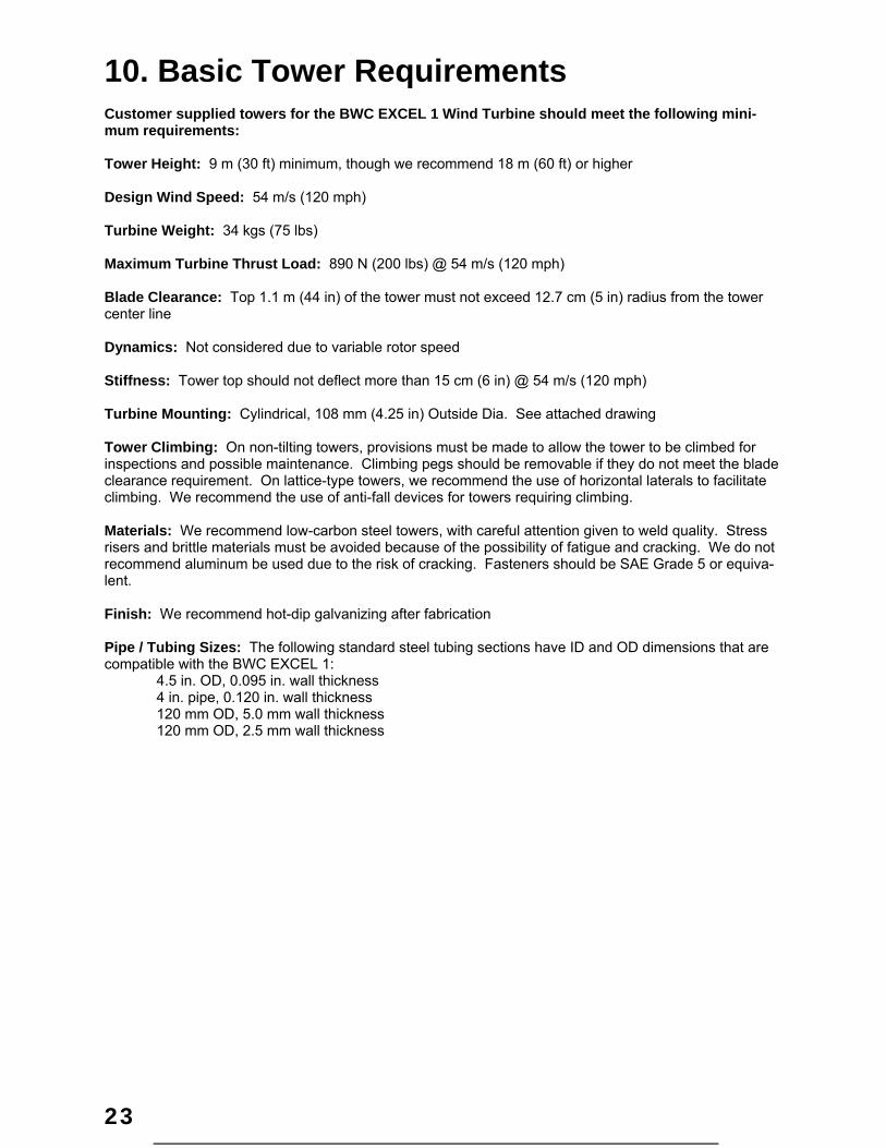
10. Basic Tower Requirements Customer supplied towers for the BWC EXCEL 1 Wind Turbine should meet the following mini-mum requirements: Tower Height: 9 m (30 ft) minimum, though we recommend 18 m (60 ft) or higher Design Wind Speed: 54 m/s (120 mph) Turbine Weight: 34 kgs (75 lbs) Maximum Turbine Thrust Load: 890 N (200 lbs) @ 54 m/s (120 mph) Blade Clearance: Top 1.1 m (44 in) of the tower must not exceed 12.7 cm (5 in) radius from the tower center line Dynamics: Not considered due to variable rotor speed Stiffness: Tower top should not deflect more than 15 cm (6 in) @ 54 m/s (120 mph) Turbine Mounting: Cylindrical, 108 mm (4.25 in) Outside Dia. See attached drawing Tower Climbing: On non-tilting towers, provisions must be made to allow the tower to be climbed for inspections and possible maintenance. Climbing pegs should be removable if they do not meet the blade clearance requirement. On lattice-type towers, we recommend the use of horizontal laterals to facilitate climbing. We recommend the use of anti-fall devices for towers requiring climbing. Materials: We recommend low-carbon steel towers, with careful attention given to weld quality. Stress risers and brittle materials must be avoided because of the possibility of fatigue and cracking. We do not recommend aluminum be used due to the risk of cracking. Fasteners should be SAE Grade 5 or equiva-lent. Finish: We recommend hot-dip galvanizing after fabrication Pipe / Tubing Sizes: The following standard steel tubing sections have ID and OD dimensions that are compatible with the BWC EXCEL 1: 4.5 in. OD, 0.095 in. wall thickness 4 in. pipe, 0.120 in. wall thickness 120 mm OD, 5.0 mm wall thickness 120 mm OD, 2.5 mm wall thickness
24
Figure 10: Tower Adapter Requirements
25
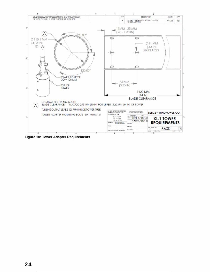
Turbine/Tower Adapter: BWC offers a tower section that can be used with customer supplied towers. Item 6612 (10 ft) and 6612-1 (5 ft) are predrilled with the turbine mounting holes and also has guy cable attachment nuts located below the blade clearance distance.
Figure 11: Top Tower Section
¼” x 20 (6 PLCS)
11mm Φ (6 PLCS)
26
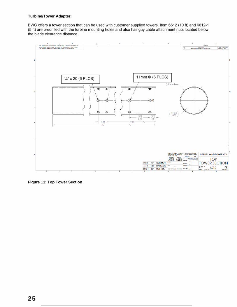
11. System Single Line Diagram
ACINPUT
SHORTING
MIDNITE SOLARTURBINE CONTROL BOXV(in) = 480VACV(out) = 600VDCI(out) = 52A
CHASSIS
15A
P3P2
3 4
DC
P1
15A
(OPTIONAL)
LA
5
CHASSIS
GROUND ROD AT BASE OF TOWER(OPTIONAL)
6
LA
5
-+
BAT
PV
BATTERYBANK
4
3 x #8AWG CU + #10AWG CU GND WIRE FOR RUNS BETWEEN 180 TO
300 FEET (INCLUDING TOWER HEIGHT). REFER TO THE
INSTALLATION MANUAL FOR OTHER CONFIGURATIONS AND DISTANCES.
MIDNITE SOLARCLASSIC 250V(in) = 250VDCV(out) = 48VDCI(out) = 52A
XL.1 WIND TURBINE1kW 3Ø OUTPUTI(max) = 15A, V(max) 180VAC
3
INDOORS
OUTDOORS
NOTES:
1. EQUIPMENT SHALL BE INSTALLED IN ACCORDANCE WITH NFPA 70 NEC ARTICLE 694.
2. SYSTEM SHALL BE INSTALLED ONLY BY QUALIFIED PERSONS PER NEC 705-6.
3. PROVIDE WARNING SIGN PER NEC 694-22(A)(4) READING "WARNING. ELECTRIC SHOCK HAZARD. DO NOT TOUCH TERMINALS. TERMINALS ON BOTH THE LINE AND THE LOAD SIDE MAY BE ENERGIZED IN THE OPEN POSITION.
4. MARK DISCONNECT "WIND ELECTRIC SYSTEM DISCONNECT" PER NEC 694.22(C)(2).
5. LIGHTNING ARRESTOR INSTALLED AT TOWER-BASE DISCONNECT SWITCH OR POWERCENTER.
6. MOUNT DISCONNECT / J-BOX ON SEPERATE POST. DO NOT MOUNT TO THE TOWER.
BERGEY WINDPOWERNORMAN, OKLAHOMA
Figure 12: Single Line Diagram (Typical)

27
12. Identification Each BWC EXCEL 1-48 wind turbine has a serial number decal located on the tower mount. The Serial Number is also written on the box that the turbine came in. We recommend writing it here as well: BWC EXCEL 1-48 Serial Number:
13. Warranty
FIVE YEAR BERGEY WARRANTY BWC XL.1 Windpower Generating Systems manufactured by Bergey Windpower Company, Inc. (herein-after called Bergey) are warranted against defects in design, workmanship, and material under normal use for which intended for five years after warranty registration or installation, whichever is first.
This warranty does not cover: 1. Towers, equipment, materials or supplies not manufactured by Bergey. 2. Damage or loss of function sustained during periods with wind speeds exceeding 120 mph (53.6 m/s). 3. Wind turbines and associated electrical/electronic equipment supplied by Bergey that have been in any way modi-
fied or altered. 4. Repairs performed by other than authorized Bergey service personnel. 5. Acts of God, incidental, or consequential damages. Bergey's limit of liability hereunder shall be to provide necessary parts and labor to repair said products installed by Bergey or by an authorized Bergey installation facility. Bergey systems not installed by the factory or by an authorized installation facility will be re-paired or replaced, at Bergey's option, when returned, transportation charges prepaid, to either the Bergey factory or an authorized Bergey Service Center. This warranty is in lieu of all other Bergey guarantees or warranties expressed or implied. No employee, agent, dealer, or other person is authorized to give warranties on behalf of Bergey. Bergey reserves the right to make design changes, improvements, and additions to its products without obligation to install such in products previously manufactured.
THIS IS A LIMITED WARRANTY

28
14. Registration Card RETURN THIS CARD TO BWC ALONG WITH PHOTOS DOCUMENTING INSTALLATION NOTE: DIGITAL PHOTOGRAPHS PREFERRED IF AVAILABLE) Return to: Bergey Windpower Company 2200 Industrial Blvd. Norman, Oklahoma 73069
BWC WIND TURBINE SYSTEM REGISTRATION CARD
OWNER NAME ___________________________________
Address _________________________________________
City, Slate, Postal Code _____________________________
Country __________________________________________
Phone (________) _________________________________
Email ____________________________________________
DEALER NAME ___________________________________
Address__________________________________________
City, Slate, Postal Code _____________________________
Country __________________________________________
Phone (________) _________________________________
LOCAL UTILITY COMPANY INFORMATION (if grid-
connected system)
Name of Utility ____________________________________
Net Metering? Yes No
HYBRID SYSTEM (If applicable)
Is turbine part of hybrid wind-PV-diesel system? Yes
No
PV array? Yes No PV Power rating _______ kW
Diesel Gen-set? Yes No Generator rating _____ kW
WIND SYSTEM MODEL __________________________
Serial No. (e.g. 2009866; near top of mainframe tube)
_____________________________________
Controller: PowerSync II VCS-10 Classic 250
Controller Serial No.____________________________
Blade Serial Numbers (e.g. 10080025; stamped on blade
root pad)
______________ _____________ _____________
Tower Type _________________ Height ____________
Anchor Type __________________________________
Wiring Run Length (Tower-to-Controller): __________ ft
Wire Size ________ gauge
Wire Type Copper Aluminum
BATTERY BANK INFORMATION (if applicable)
Battery Manufacturer & Model ______________________
Battery Bank Voltage 24V 48V 120V 240V
Battery Bank Amp Hours _________
Number of Battery Strings ________
Inverter Manufacturer and Model____________________
OWNER’S or DEALER’S SIGNATURE _________________________________________
DATE SYSTEM INSTALLED _________________________________________________
WARRANTY REPAIR IS PERFORMED ONLY AFTER FACTORY AUTHORIZATION. PLEASE RETURN THIS CARD AND PHOTO-GRAPHS OF INSTALLATION PROMPTLY IN ORDER TO ASSURE COVERAGE. Required Photographs
1. Complete tower - turbine system view 2. Anchor photos including all anchor hardware 3. Photos showing all grounding connections 4. Turnbuckle photos showing safety cables 5. Installed rebar cages for anchors, pads, piers and any other concrete items 6. Controller location and environment 7. Controller interior showing wiring connections 8. Interior of tower-base disconnect switch showing fuses and wiring connections

29
Appendix
How to Avoid the Most Common Mistakes When Installing an EXCEL 1
1. DO NOT install the wind turbine close to a steep slope or cliff. If the wind can blow up at an angle as it
hits the wind turbine the furling will be hampered and the turbine will experience excessive loads and vi-bration. This is most important from the prevailing wind direction. Try to keep the tower at least two tow-er heights back from steep slopes.
2. DO USE thimbles on all guy wires and position the lower malleable clip close to the thimble so that the guy wire “captures” the thimble securely. Not using thimbles or not securing them can lead to guy failure and tower collapse. Thimbles are not required on knuckle-end anchors, such as double-eye and triple-eye anchors.
3. DO USE temporary yellow polypropylene ropes from the top of the gin pole to the side anchors when lift-ing or raising the tower. The ropes prevent the gin-pole from falling sideways when vertical, and center it as the tower is being raised.
4. DO USE ring type crimped lugs.DO NOT use mechanical screw lugs, 5. DO tighten blades nuts in proper sequence to the proper torque. 6. DO NOT overtorque the blade nuts, this will crush the blade. 7. DO perform yearly inspections, including proper guy line tensioning

MNTCB Turbine Control Box Installation Instructions (continued)
10-201-1 REV P1 Page 1 of 4
The MNTCB Turbine Control Box is designed for use with three phase turbines.
Applications: Turbine Braking
Three phase AC to DC converter
Turbine disconnect
Features: Heavy Duty three phase bridge rectifier
Converts three phase AC to DC
Provides disconnect protected by circuit breakers
Chassis ground bus bar with 14 useable openings (10 #14-6 and 4#1/0-14)
Knockouts for in and out on bottom and sides
Top surface is available to bring conduit in from directly above the enclosure
MNTCB
Turbine Control Box

MNTCB Turbine Control Box Installation Instructions (continued)
10-201-1 REV P1 Page 2 of 4
IMPORTANT SAFETY INSTRUCTIONS
SAVE THESE INSTRUCTIONS - These instructions contain important safety and operating instructions for the MidNite
Solar MNTCB Turbine Control Box boxes.
Before installing and using this product read all instructions and safety information contained in this manual.
If you do not fully understand any of the concepts, terminology, or hazards outlined in these instructions, please refer
installation to a qualified dealer, electrician or installer. These instructions are not meant to be a complete explanation of a
renewable energy system.
GENERAL PRECAUTIONS
WORKING WITH OR IN THE VICINITY OF A LEAD ACID BATTERY, SEALED OR VENTED IS DANGEROUS.
VENTED BATTERIES GENERATE EXPLOSIVE GASES DURING NORMAL OPERATION. FOR THIS REASON, IT
IS VERY IMPORTANT THAT BEFORE SERVICING EQUIPMENT IN THE VICINITY OF LEAD-ACID BATTERIES
YOU REVIEW AND FOLLOW THESE INSTRUCTIONS CAREFULLY.
If service or repair should become necessary, contact MidNite Solar Inc. Improper servicing may result in a risk of shock, fire
or explosion. To reduce these risks, disconnect all wiring before attempting any maintenance or cleaning.
Do not work alone. Someone should be in the range of your voice or close enough to come to your aid when you work with
or near electrical equipment.
Remove rings, bracelets, necklaces, watches etc. when working with batteries, photovoltaic modules or other electrical
equipment. Power from an illuminated photovoltaic array makes a very effective arc welder with dire consequences if one of
the welded pieces is on your person.
All electrical work must be performed in accordance with local, state and federal electrical codes.
Always disconnect all sources of energy prior to installing or performing maintenance on the Turbine Control Box.
Disclaimer
Unless specifically agreed to in writing, MidNite Solar Inc.
(a) Makes no warranty as to the accuracy, sufficiency or suitability of any technical or other information provided in its
manuals or other documentation.
(b) Assumes no responsibility or liability for loss or damage whether direct, indirect, consequential or incidental, which
might arise out of use of such information. The use of any such information will be entirely at the user's risk.
MNTCB Turbine Control Box Installation Instructions (continued)
10-201-1 REV P1 Page 3 of 4
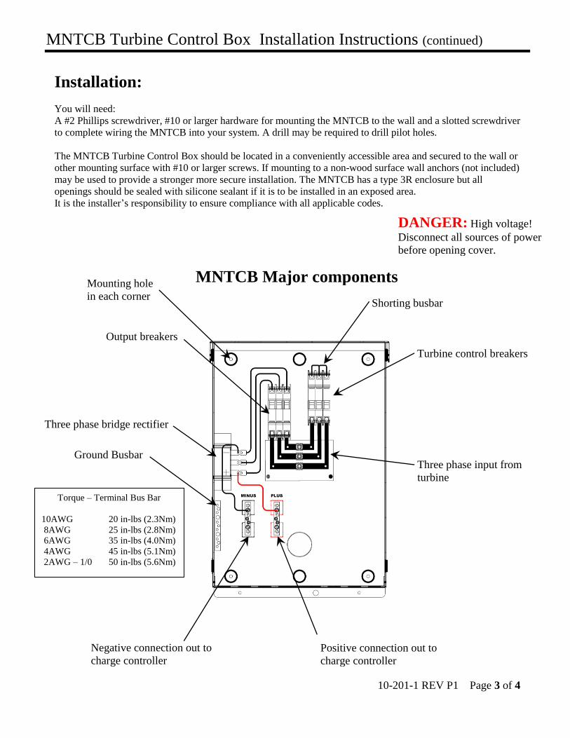
Torque – Terminal Bus Bar
10AWG 20 in-lbs (2.3Nm)
8AWG 25 in-lbs (2.8Nm) 6AWG 35 in-lbs (4.0Nm)
4AWG 45 in-lbs (5.1Nm) 2AWG – 1/0 50 in-lbs (5.6Nm)
Installation:
You will need:
A #2 Phillips screwdriver, #10 or larger hardware for mounting the MNTCB to the wall and a slotted screwdriver
to complete wiring the MNTCB into your system. A drill may be required to drill pilot holes.
The MNTCB Turbine Control Box should be located in a conveniently accessible area and secured to the wall or
other mounting surface with #10 or larger screws. If mounting to a non-wood surface wall anchors (not included)
may be used to provide a stronger more secure installation. The MNTCB has a type 3R enclosure but all
openings should be sealed with silicone sealant if it is to be installed in an exposed area.
It is the installer’s responsibility to ensure compliance with all applicable codes.
Positive connection out to
charge controller
Ground Busbar
Three phase bridge rectifier
Negative connection out to
charge controller
Three phase input from
turbine
Turbine control breakers
Output breakers
Shorting busbar
Mounting hole
in each corner
MNTCB Major components
DANGER: High voltage!
Disconnect all sources of power
before opening cover.

MNTCB Turbine Control Box Installation Instructions (continued)
10-201-1 REV P1 Page 4 of 4
Midnite Solar 17722 - 67thAve N.E. Arlington, Wa 98223 U.S.A.
360.403.7207 [email protected]
Wiring: First verify that the turbine is stopped or disconnected and that no power is present, then, remove the desired
knockout(s) on the side or bottom and route the three phase output wires from the turbine to the three box lugs
just below the breakers (Page 3).
Connect phase 1 to the top box lug, phase 2 to the middle box lug and phase three to the bottom box lug. The
order of the phases is not critical so if desired phase 1,2 and 3 can actually be in any order. Be sure to use a
heavy enough gauge of wire to carry all the current from the turbine.
Now connect the DC output from the MNTCB (Page 3) to the input of the charge controller (refer to the
documentation that came with your controller). Be sure to observe proper polarity. Be sure to use a heavy
enough gauge of wire to carry all the current from the turbine.
Connect an earth ground to the ground terminal block at the lower left side of the MNTCB (Page 3)
The installer must ensure compliance with all applicable wiring codes including ANSI/NFPA 70.
Check your work before applying power!
Operating the MNTCB:
The three ganged circuit breakers to the left connect and disconnect power from the turbine to the charge
controller.
The three ganged breakers to the right connect the turbine to the shorting busbar to slow the turbine to a near
stop.
To operate the turbine and charge batteries push all breakers to the up position.
Notice that one set of breakers is upside down. This is so that when all the breakers are up the turbine is not
slowed and power is presented to the charge controller.
When all breakers are down the turbine is slowed and the charge controller is disconnected.
The breakers should typically be all up or all down however, if the left breakers are down and the right ones
are up then the turbine would be free-wheeling with no load from the shorting busbar or the charge controller.
This is not recommended because the turbine could overspeed in a high wind.
If the right breakers are down and the left ones are up then the turbine is slowed and the charge controller is
connected. This is not recommended or useful.
DANGER: High voltage! Disconnect all sources of power before opening cover.

1 | P a g e
MidNite Solar Classic
Owner’s Manual
Standard Classic Classic Lite
This Manual covers models Classic 150, 200, 250 &
250KS as well as the Classic 150, 200, 250 & 250KS LITE

2 | P a g e
The MidNite Solar Classic charge controller conforms to UL 1741, Safety for Inverters, Converters,
Controllers and Interconnection System Equipment for Use With Distributed Energy Resources,
Second Edition, May 7, 1999 with revisions through January 28, 2010 and
CAN/CSA C22.2 No. 107.1: 2001/09/01 Ed: 3 (R2006)
Notice of Copyright
MidNite Solar's Classic charge controller User’s Manual
Copyright ⓒ 2010 all rights reserved.
MidNite Solar Inc. reserves the right to revise this document and to periodically make changes to the
content hereof without obligation or organization of such revisions or changes unless required to do so
by prior arrangement.
Disclaimer
Unless specifically agreed to in writing, MidNite Solar Inc.
(a) Makes no warranty as to the accuracy, sufficiency or suitability of any technical or other
information provided in its manuals or other documentation.
(b) Assumes no responsibility or liability for loss or damage whether direct, indirect, consequential or
incidental, which might arise out of use of such information. The use of any such information will be
entirely at the user's risk.
Contact Information
Telephone: 360.403.7207
Fax: 360.691.6862
Email: [email protected]
Web: www.midnitesolar.com
3 | P a g e
Table of Contents
Glossary of Terms..................................................................................................................................... 5 Scope .......................................................................................................................................................... 7 Introduction .............................................................................................................................................. 7 Classic Power Curves ............................................................................................................................... 9 Unpacking the Classic ............................................................................................................................ 11
Removing and installing the front cover on the Classic ..................................................................... 12 Mounting the Classic ............................................................................................................................. 13
Alternative Mounting .......................................................................................................................... 15 Dimensions...................................................................................................................................... 15
Sealed or Vented .................................................................................................................................. 16
Battery Temperature Compensation .................................................................................................... 16 Classic Stacking Cable Routing and Installation Guidelines ............................................................. 17
Battery Temperature Sensor Installation ............................................................................................. 18 Chassis Grounding ................................................................................................................................. 20
DC System Grounding ........................................................................................................................ 20
DC GFP (Ground Fault Protection) ..................................................................................................... 21 Disabling GFP ..................................................................................................................................... 21
Wiring the Classic .................................................................................................................................. 22 DC Terminal Connector ...................................................................................................................... 25
Over Current Protection and Wire Size Requirements ...................................................................... 25 Current Rating ..................................................................................................................................... 25
Over Current Protection ...................................................................................................................... 26 Long Distance Wire Runs ................................................................................................................... 26
Connecting the Classic to the Clipper ................................................................................................. 26 Maximum and Minimum Wire Size .................................................................................................... 27
Equalization Manual and Auto ............................................................................................................. 28 Equalization with the Classic Lite ...................................................................................................... 28 Equalization with the standard Classic ............................................................................................... 29
Standard Classic programming ............................................................................................................ 30 Commissioning the Classic (Quick Start) ........................................................................................... 30
Battery Charge Stages and Meanings ................................................................................................. 30
Resting ............................................................................................................................................ 30
Mode is OFF ................................................................................................................................... 31 Adjusting Absorb, Equalize and Float Voltages .................................................................................. 31 Current Limit....................................................................................................................................... 31 LED Modes and the “Blinking Red LED”.......................................................................................... 31 Calibrating Battery and PV Voltage .................................................................................................... 32
Configuring DC Input Source ............................................................................................................. 32 Configuring the Classic for Wind Input Source .................................................................................. 34 Setting the Date and Time ................................................................................................................... 35 Setting Longitude and Latitude ........................................................................................................... 35
Configuring Auxiliary Input/Output ................................................................................................... 35 Aux 1 Function................................................................................................................................ 39 Aux 2 Function. Output/Input ......................................................................................................... 40
Setting the MNGP features ................................................................................................................. 41 Navigating the Menu's ........................................................................................................................ 41

4 | P a g e
Viewing Other MidNite Products on the Display ............................................................................... 42
Connecting Classic to Two MNGPs/Network cable ........................................................................... 42 Arc Fault ............................................................................................................................................. 43 View Faults and Warning's .................................................................................................................. 44 View Logged Data .............................................................................................................................. 44
Graphical Logging Display modes ..................................................................................................... 47 Dealer Information Screen .................................................................................................................. 49
Classic Lite Programming ..................................................................................................................... 50 LED explanations ................................................................................................................................ 50 Programming ....................................................................................................................................... 51
Dip Switches ....................................................................................................................................... 51
Section 1 Switch settings explained ................................................................................................. 53
Section 2 Switch settings explained ................................................................................................. 54 Battery voltage and time settings .................................................................................................... 57
Using MNGP Remote to program a Classic Lite ................................................................................ 58
Programming the Lite with a Networked Standard Classic ................................................................ 58 Programming the Lite with the Local App .......................................................................................... 59 Clearing Faults .................................................................................................................................... 59 Notes on the Lite ................................................................................................................................. 59
Explanations of Solar and Legacy ...................................................................................................... 59
Uploading New Firmware to the Classic .............................................................................................. 60
Connecting the Classic to the Internet ................................................................................................. 63 Networking.......................................................................................................................................... 63
Network Setup Through the MNGP ................................................................................................... 64 Web Access ......................................................................................................................................... 66 Local Network..................................................................................................................................... 66
Positive Ground systems ........................................................................................................................ 66
HyperVOC ™ ......................................................................................................................................... 67 Troubleshooting ...................................................................................................................................... 68 Specifications Electrical ......................................................................................................................... 69
Specifications Mechanical ..................................................................................................................... 70 Default Battery charge set points ......................................................................................................... 71
Optional accessories ............................................................................................................................... 71
Regulatory Approval .............................................................................................................................. 71 Warranty ................................................................................................................................................. 72 Appendix ................................................................................................................................................. 73
Aux 1 and Aux 2 Graphs/Jumpers ...................................................................................................... 73 Aux 1 Voltage-Time Relation (Relay/12v) ......................................................................................... 74 ............................................................................................................................................................. 74 Aux 2 Voltage-Time Relation (PWM) ................................................................................................ 74
Classic Breaker sizing ......................................................................................................................... 75 Label Set from Classic ........................................................................................................................ 77 MODBUS............................................................................................................................................ 78 RS232 Jack Pin Out .......................................................................................................................... 102
5 | P a g e
Glossary of Terms
Absorb – Constant voltage charge stage to fill the batteries. The controller is regulating so maximum power will
not be seen at this time. The Absorb timer is also counting down to the switch to Float.
A-EQ-R – This will reload the Auto Equalize counters, basically it will start the counters from day 1.
AF – Arc Fault, See page 43 for more info on arc fault protection.
Arc Adjust – This menu is where you adjust the Arc Fault sensitivity. For info on Arc Fault see page 43.
A-RST – Auto reset of the Classic controller, The Classic will reboot around Midnight every night when this is
enabled. This is useful for very remote sites where a loss of internet capability for example would be a hard ship.
Aux – Auxiliary relays. The Classic has 2 relays: Aux 1 can be configured as a 12 volt signal or a dry relay, Aux
2 can be used as a PWM signal output. Refer to page 35 for more Aux info.
BLK – Bulk MPPT Mode. By using the up arrow in Tweaks under BLK you can force the Classic into Bulk
mode.
Bulk MPPT - Maximum current charge stage, the Classic is trying to bring the batteries to the Absorb voltage
set point. We are basically putting all available power into the batteries.
Comm – This Menu allows adjustment of things like Mod Bus port, USB Mode and MNGP address.
DvrtCnt – When enabled, allows the charge stage timers to continue to run when the diversion modes are hold-
ing the battery voltage just below the actual set point.
Equalize - Constant voltage charge stage to equalize the batteries. The controller is regulating so maximum
power will not be seen at this time. The Equalize timer is also counting down to the switch to Float.
EQ MPPT - Maximum current charge stage, the Classic is trying to bring the batteries to the Equalize voltage
set point. We are basically putting all available power into the batteries.
Float – Constant voltage charge stage with a lower voltage than the Absorb charge point. The controller is regu-
lating so maximum power will not be seen at this time.
Float MPPT – Maximum current charge stage, the Classic is trying to bring the batteries to the Float voltage set
point. We are basically putting all available power into the batteries.
FLT – Float mode. By using the up arrow in Tweaks under FLT you can force the Classic into Float mode.
GF – Ground Fault, See page 21 for more info on ground fault protection.
Got Comm – Indicates a lack of communication between the display and the Classic. Consult Troubleshooting
for information page 68.
6 | P a g e
Insomnia – This when enabled, will keep the Classic from going to Resting. This is intended for hydro mode
only where you may need time to open water valves and do not want to wait for the Classic to wake up.
LED-MODE – This selection lets you pick the function of the 6 visible LED’s on a standard Classic.
LMX – LoMax, This enables the Classic to track the input voltage all the way down to Battery voltage. When
disabled the Classic will stop tracking the input around 5 volts above the battery voltage. When the input voltage
is within a couple volts of the battery voltage the inductors can “Sing” this is usually not very loud and will do
no harm.
Local App – Monitoring software included with the Classic for monitoring over the Local Network or Internet.
MNGP – Midnite Graphical interface Panel. This is the graphical display included with the standard Classic
controller.
MNLP – MidNite LED interface Panel. This is the LED display that comes standard with the Classic Lite.
Mode – This menu lets you turn the charging ability of the controller On / Off as well as lets you select the DC
input source. See page 30 for info on the Mode menu.
Mod Bus – a standard protocol used for communications. We have published our protocol to allow users to in-
terface with the Classic. See page 78 for our Mod Bus protocol.
My MidNite – Web based monitoring for the Classic. (Not available yet)
NiteLog – When enabled allows the Classic to log data in the evening when the Classic is Resting.
PV Shading – This indicates the Maximum power point voltage is less than half the open circuit voltage.
Pwr Save – Allows you to adjust the time the Backlight stays on.
Resting – The Classic is not charging the battery due to low light. For reasons Resting will appear please see
page 30.
Shade – When enabled the Classic will show PV Shading on the display when the Maximum power point volt-
age is less than half the open circuit voltage.
T-Comp – Temperature compensation using a temperature sensor to measure the ambient temperature of the
battery bank and will adjust the voltage set points up or down accordingly to ensure a full battery. There are 3
parameters to set Minimum and Maximum adjusted voltage as well as volts per degree C per Cell. Typically this
is -.05 mV but please consult your battery manufacturer. See page 16 for Temperature compensation info.
Tweaks – This menu has all the advanced adjustments for the Classic. For example: Voltage off set adjustments
etc.
VBatt – Battery voltage, measured at the battery terminals of the Classic.
VOC – Open Circuit Voltage, unloaded voltage measurement.
Vpv – Input voltage, measured at the input terminals of the Classic.

7 | P a g e
Web Access – When enabled allows the Classic to send data over the internet to My MidNite’s Server for you to
view when wanted.
Scope
This Manual provides safety guidelines and installation information for the Classic charge controller. It
does not provide brand specific information about photovoltaic panels, batteries etc. Contact the
manufacturer of other components in the system for relevant technical data.
Introduction
The MidNite Classic charge controller is unique in its ability to be used for a great variety of DC input
sources. The Classic is designed to regulate DC input from PV, and Approved Hydro and Wind turbines
for other DC sources please contact MidNite Solar tech support.. The Classic 150, 200 and 250 are
designed to work with 12, 24, 36, 48, 60 and 72 volt battery banks.
The Classic250KS is designed to charge up to a 120V nominal battery bank.
The Classic can be installed stand alone or as a multi-unit networked installation.
Standard features of the Classic charge controller include:
*3 input operating voltage ranges 150, 200 and 250 VDC
*Multiple DC input options (example Solar, Wind or Hydro)
*Wizard driven setup interface including voice and help screens
*Graphical display
*Previous 180 days of operational data logged
*Internet ready
This Manual covers Classic 150, Classic 200 Classic 250 and the Classic 250KS. It covers the
installation, wiring and use of the Classic charge controller.
WARNING Warnings signs identify conditions or practices that could result in personal injury or loss of
life.
CAUTION Cautions identify conditions or practices that could result in damage to the unit or other
equipment.
MIDNITE SOLAR CHARGE CONTROLLER INSTALLATION GUIDELINES AND SAFETY
INSTRUCTIONS
This product is intended to be installed as part of a permanently grounded electrical system as shown in the
system configuration sections. The following important restrictions apply unless superseded by local or national
codes:

8 | P a g e
•The System's DC Negative conductor must not be bonded to earth ground. The Classic does this with its
internal Ground Fault Protection circuitry. The battery negative and ground are not bonded together directly but
are connected together by the Classic’s internal GFP device. All negative conductor connections must be kept
separate from the grounding conductor connections. The equipment ground terminal inside the Classic must be
connected to Earth Ground for the internal DC-GFP to work. Continue
• With the exception of certain telecom applications, the Charge Controller should never be positive grounded.
• The Charge Controller equipment ground is marked with this symbol: • If damaged or malfunctioning, the Charge Controller should only be disassembled and repaired by a qualified
service center. Please contact your renewable energy dealer/installer for assistance. Incorrect reassembly risks
malfunction, electric shock or fire.
• The Charge Controller is designed for indoor installation or installation inside a weatherproof enclosure. It
must not be exposed to rain and should be installed out of direct sunlight.
For routine, user-approved maintenance:
• Turn off all circuit breakers, including those to the solar modules, batteries and related electrical connections
before performing any maintenance.
Standards and Requirements
All installations must comply with national and local electrical codes; professional installation is recommended.
The NEC in the USA requires a DC ground fault interrupter for all residential PV installations. NEC2011
requires an ARC FAULT detector on all charge controllers and inverters operating above 80VDC. Both of these
devices are built into the Classic.
DC and Battery-Related Installation Requirements:
All DC cables must meet local and national codes.
Shut off all DC breakers before connecting any wiring.
Torque all the Charge Controller’s wire lugs and ground terminals to the specs found on page 19. Copper wiring must be rated at 75° C or higher.
Keep cables close together (e.g., using a tie-wrap) as much as possible to reduce inductance.
Ensure both cables pass through the same knockout and conduit to allow the inductive currents to
cancel.
DC battery over-current protection must be used as part of the installation on the input and output.
Breakers between the battery and the Classic must meet UL489 standards.
Breakers between the DC source and the Classic must meet UL1077 or UL489 standards.
Design the battery enclosure to prevent accumulation of hydrogen gas at the top of the enclosure. Vent the
battery compartment from the highest point to the outside. A sloped lid can also be used to direct the flow of
hydrogen to the vent opening. Sealed (AGM, Gel etc) batteries do not normally require ventilation. Consult your
battery manufacturer for details.
WARNING: PERSONAL PRECAUTIONS DURING INSTALLATION
WARNING BATTERIES PRESENT RISK OF
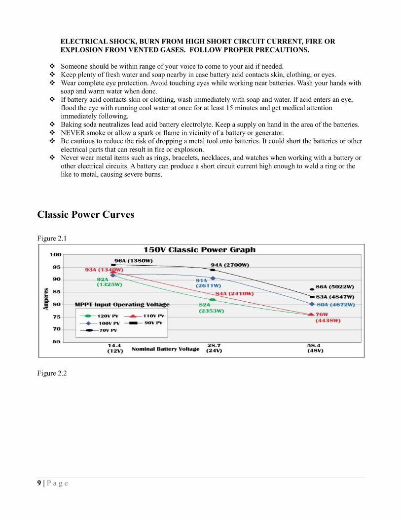
9 | P a g e
ELECTRICAL SHOCK, BURN FROM HIGH SHORT CIRCUIT CURRENT, FIRE OR
EXPLOSION FROM VENTED GASES. FOLLOW PROPER PRECAUTIONS.
Someone should be within range of your voice to come to your aid if needed.
Keep plenty of fresh water and soap nearby in case battery acid contacts skin, clothing, or eyes.
Wear complete eye protection. Avoid touching eyes while working near batteries. Wash your hands with
soap and warm water when done.
If battery acid contacts skin or clothing, wash immediately with soap and water. If acid enters an eye,
flood the eye with running cool water at once for at least 15 minutes and get medical attention
immediately following.
Baking soda neutralizes lead acid battery electrolyte. Keep a supply on hand in the area of the batteries.
NEVER smoke or allow a spark or flame in vicinity of a battery or generator.
Be cautious to reduce the risk of dropping a metal tool onto batteries. It could short the batteries or other
electrical parts that can result in fire or explosion.
Never wear metal items such as rings, bracelets, necklaces, and watches when working with a battery or
other electrical circuits. A battery can produce a short circuit current high enough to weld a ring or the
like to metal, causing severe burns.
Classic Power Curves
Figure 2.1
Figure 2.2
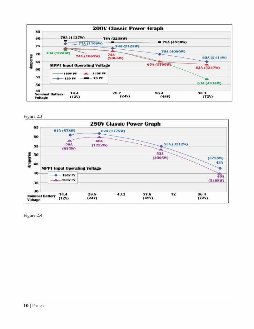
10 | P a g e
Figure 2.3
Figure 2.4
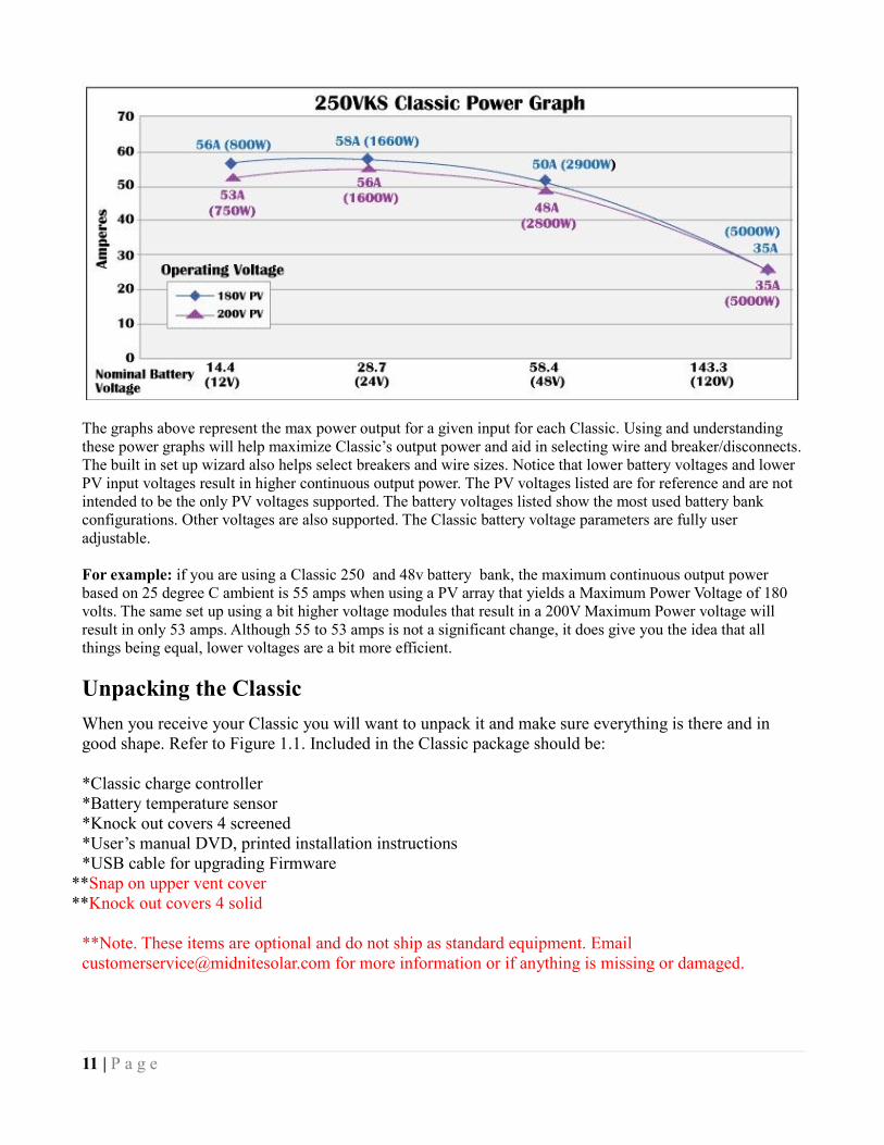
11 | P a g e
The graphs above represent the max power output for a given input for each Classic. Using and understanding
these power graphs will help maximize Classic’s output power and aid in selecting wire and breaker/disconnects.
The built in set up wizard also helps select breakers and wire sizes. Notice that lower battery voltages and lower
PV input voltages result in higher continuous output power. The PV voltages listed are for reference and are not
intended to be the only PV voltages supported. The battery voltages listed show the most used battery bank
configurations. Other voltages are also supported. The Classic battery voltage parameters are fully user
adjustable.
For example: if you are using a Classic 250 and 48v battery bank, the maximum continuous output power
based on 25 degree C ambient is 55 amps when using a PV array that yields a Maximum Power Voltage of 180
volts. The same set up using a bit higher voltage modules that result in a 200V Maximum Power voltage will
result in only 53 amps. Although 55 to 53 amps is not a significant change, it does give you the idea that all
things being equal, lower voltages are a bit more efficient.
Unpacking the Classic
When you receive your Classic you will want to unpack it and make sure everything is there and in
good shape. Refer to Figure 1.1. Included in the Classic package should be:
*Classic charge controller
*Battery temperature sensor
*Knock out covers 4 screened
*User’s manual DVD, printed installation instructions
*USB cable for upgrading Firmware
**Snap on upper vent cover
**Knock out covers 4 solid
**Note. These items are optional and do not ship as standard equipment. Email
[email protected] for more information or if anything is missing or damaged.

12 | P a g e
Removing and installing the front cover on the Classic
Removing the front art deco cover is required to gain access to the wiring compartment.
Be aware if this is not the first removal of this cover there is a cable connecting the cover to the
electronics. Do not pull hard or fast as damage could occur.
To remove the front cover of the Classic in preparation for installation, remove the 4 Phillips head
screws with a #2 Phillips screwdriver. Lift the front half of the Classic casting off. You will need to
unplug the display cable. It works the same as any phone cable.
To re-install the front cover of the Classic you will need to plug in the display cable and carefully route
it around the components on the circuit board as you set the cover in place. See Figure 1.2 Do not force
the cover if it does not seat into place easily stop and look for any cables or wires that may be
interfering. With the cover seated in place install the four Phillips screws with a #2 Phillips screwdriver.
Figure 1.2
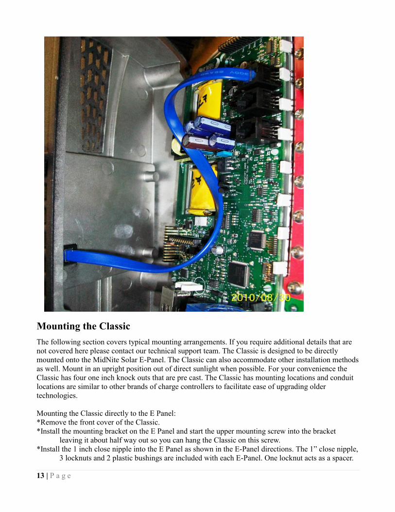
13 | P a g e
Mounting the Classic
The following section covers typical mounting arrangements. If you require additional details that are
not covered here please contact our technical support team. The Classic is designed to be directly
mounted onto the MidNite Solar E-Panel. The Classic can also accommodate other installation methods
as well. Mount in an upright position out of direct sunlight when possible. For your convenience the
Classic has four one inch knock outs that are pre cast. The Classic has mounting locations and conduit
locations are similar to other brands of charge controllers to facilitate ease of upgrading older
technologies.
Mounting the Classic directly to the E Panel:
*Remove the front cover of the Classic.
*Install the mounting bracket on the E Panel and start the upper mounting screw into the bracket
leaving it about half way out so you can hang the Classic on this screw.
*Install the 1 inch close nipple into the E Panel as shown in the E-Panel directions. The 1” close nipple,
3 locknuts and 2 plastic bushings are included with each E-Panel. One locknut acts as a spacer.
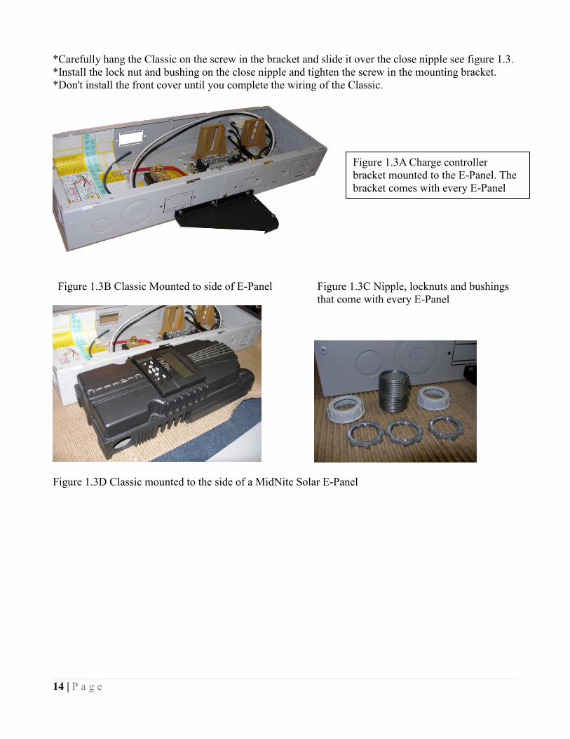
14 | P a g e
*Carefully hang the Classic on the screw in the bracket and slide it over the close nipple see figure 1.3.
*Install the lock nut and bushing on the close nipple and tighten the screw in the mounting bracket.
*Don't install the front cover until you complete the wiring of the Classic.
Figure 1.3B Classic Mounted to side of E-Panel Figure 1.3C Nipple, locknuts and bushings
that come with every E-Panel
Figure 1.3D Classic mounted to the side of a MidNite Solar E-Panel
Figure 1.3A Charge controller
bracket mounted to the E-Panel. The
bracket comes with every E-Panel
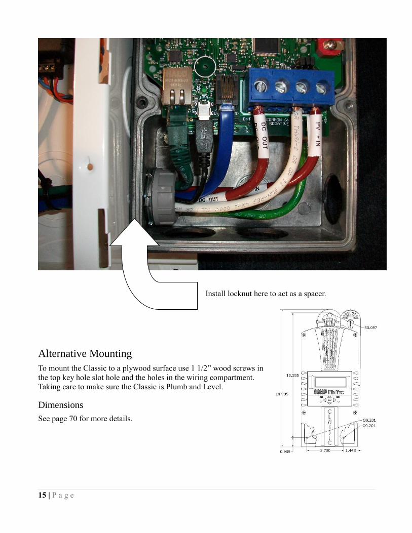
15 | P a g e
Install locknut here to act as a spacer.
Alternative Mounting
To mount the Classic to a plywood surface use 1 1/2” wood screws in
the top key hole slot hole and the holes in the wiring compartment.
Taking care to make sure the Classic is Plumb and Level.
Dimensions
See page 70 for more details.

16 | P a g e
Sealed or Vented
The Classic has the ability to be sealed for protection from salt air or dust. It comes from the factory
Vented. If you live in a dusty or salt air environment you may wish to seal the Classic. Sealing the
Classic does not make the unit water resistant. To seal the Classic install the solid plastic knock out
covers into any unused knock outs and snap the upper vent cover onto the Classic as seen in the photo
below. Note that the Classic will be slightly de-rated (puts out less power) by sealing it. Refer to the
specifications page of the owner’s manual for the ratings in the sealed mode. To obtain the parts
necessary to seal the Classic please contact our Technical Support Team. Refer to Figure 1.4 and 1.5
Figure 1.4 Figure 1.5
Battery Temperature Compensation
The Classic comes with a battery temperature sensor (BTS). This sensor raises or lowers charge voltage
based on temperature. Connect BTS to the BATT TEMP jack. (Refer to Battery Temperature Sensor
Installation 18) Battery temperature menu appears as T-Comp in the BATTERY MENU. In this menu
you can change the voltage compensation as needed. If the BTS is disconnected or shorted the Classic
will automatically use the default charge voltages non-compensated.

17 | P a g e
Classic Stacking Cable Routing and Installation Guidelines
The Classic uses a 4 conductor phone cable to communicate with other Classic's or other MidNite products. This
cable is a standard 4 conductor phone cable and simply plugs into the jack on the Master Classic labeled slave.
Plug the other end into the master jack on the second device (Slave). There is a plastic clamp located on the
circuit board for routing the network cables above the USB jack so they stay tied down and out of the way.
Refer to figure 1.7A and 1.7B
Figure 1.7A Master / Slave hook up
Master Classic Slave Classic
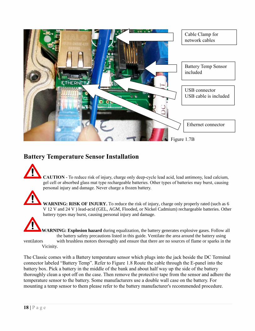
18 | P a g e
Figure 1.7B
Battery Temperature Sensor Installation
CAUTION - To reduce risk of injury, charge only deep-cycle lead acid, lead antimony, lead calcium,
gel cell or absorbed glass mat type rechargeable batteries. Other types of batteries may burst, causing
personal injury and damage. Never charge a frozen battery.
WARNING: RISK OF INJURY. To reduce the risk of injury, charge only properly rated (such as 6
V 12 V and 24 V ) lead-acid (GEL, AGM, Flooded, or Nickel Cadmium) rechargeable batteries. Other
battery types may burst, causing personal injury and damage.
WARNING: Explosion hazard during equalization, the battery generates explosive gases. Follow all
the battery safety precautions listed in this guide. Ventilate the area around the battery using
ventilators with brushless motors thoroughly and ensure that there are no sources of flame or sparks in the
Vicinity.
The Classic comes with a Battery temperature sensor which plugs into the jack beside the DC Terminal
connector labeled “Battery Temp”. Refer to Figure 1.8 Route the cable through the E-panel into the
battery box. Pick a battery in the middle of the bank and about half way up the side of the battery
thoroughly clean a spot off on the case. Then remove the protective tape from the sensor and adhere the
temperature sensor to the battery. Some manufacturers use a double wall case on the battery. For
mounting a temp sensor to them please refer to the battery manufacturer's recommended procedure.
Battery Temp Sensor
included
Cable Clamp for
network cables
USB connector
USB cable is included
Ethernet connector
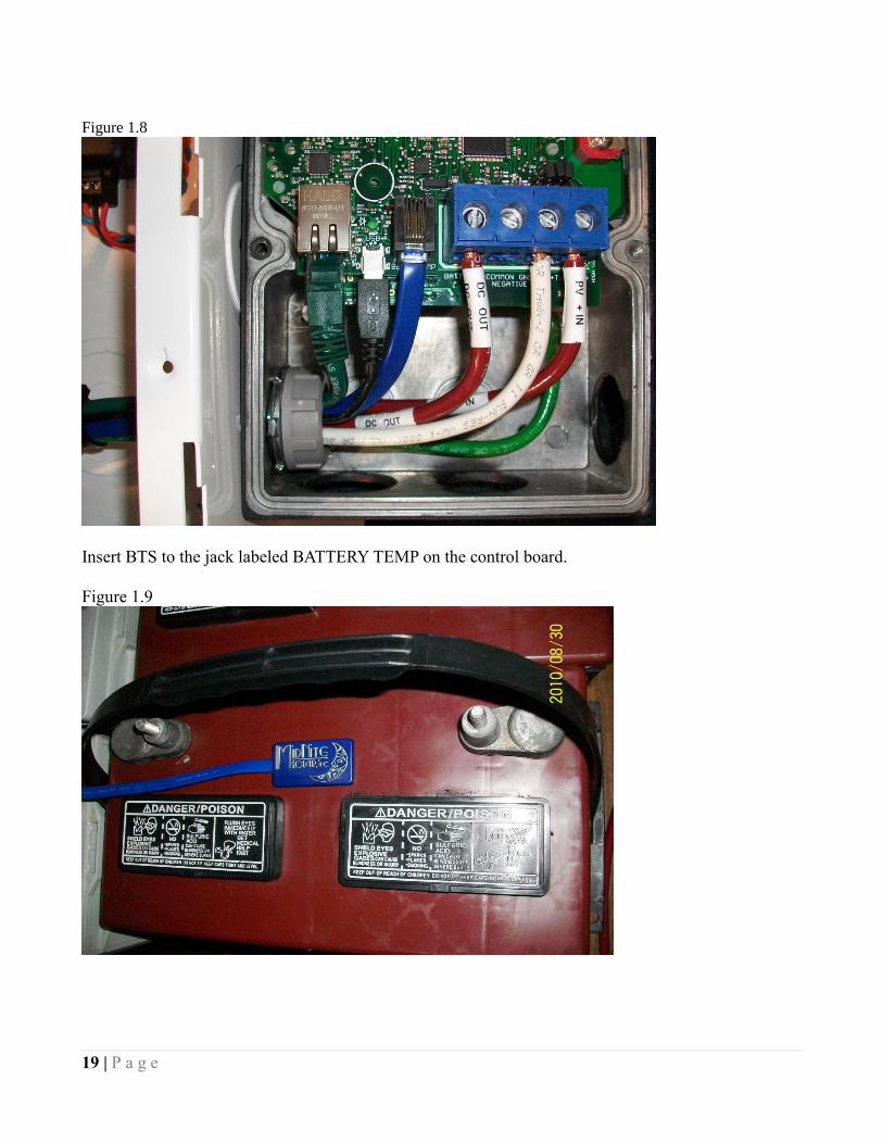
19 | P a g e
Figure 1.8
Insert BTS to the jack labeled BATTERY TEMP on the control board.
Figure 1.9

20 | P a g e
Chassis Grounding
In all installations the Classic chassis should be connected to ground. For systems with a battery
breaker sized 60 amps and smaller 10 AWG (6 mm2) copper is generally sufficient. For systems with a
battery breaker sized 100 amps and smaller 8 AWG (10 mm2) copper is required. For grounding
conductor requirements on your specific installation please consult your local electrical code. The
chassis grounding terminal is in the upper right corner of the electrical connection compartment see
DC System Grounding
The Classic charge controller is designed to work with Negative Ground, Positive Ground or
Ungrounded power systems. In grounded systems, dc negative may be connected to ground either
externally or by using the Classic’s internal grounding jumper, shown on figure 2.1. The internal
grounding jumper should only be installed when the Classic’s GFP is enabled. In a system with
multiple charge controllers the grounding jumper should be installed on every charge controller. In
Positive ground or Ungrounded systems the GFP jumper must be removed. See Figure 2.1 Also note
that with Positive ground there will be items still referenced to battery negative that can complete a
short circuit of the battery bank. These items include but are not limited to the USB Cable and the
Ethernet jack. Please contact Technical support for assistance on Positive ground systems.
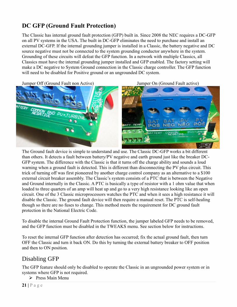
21 | P a g e
DC GFP (Ground Fault Protection)
The Classic has internal ground fault protection (GFP) built in. Since 2008 the NEC requires a DC-GFP
on all PV systems in the USA. The built in DC-GFP eliminates the need to purchase and install an
external DC-GFP. If the internal grounding jumper is installed in a Classic, the battery negative and DC
source negative must not be connected to the system grounding conductor anywhere in the system.
Grounding of these circuits will defeat the GFP function. In a network with multiple Classics, all
Classics must have the internal grounding jumper installed and GFP enabled. The factory setting will
make a DC negative to System Ground connection in the Classic charge controller. The GFP function
will need to be disabled for Positive ground or an ungrounded DC system.
Jumper Off (Ground Fault non Active) Jumper On (Ground Fault active)
The Ground fault device is simple to understand and use. The Classic DC-GFP works a bit different
than others. It detects a fault between battery/PV negative and earth ground just like the breaker DC-
GFP system. The difference with the Classic is that it turns off the charge ability and sounds a loud
warning when a ground fault is detected. This is different than disconnecting the PV plus circuit. This
trick of turning off was first pioneered by another charge control company as an alternative to a $100
external circuit breaker assembly. The Classic’s system consists of a PTC that is between the Negative
and Ground internally in the Classic. A PTC is basically a type of resistor with a 1 ohm value that when
loaded to three quarters of an amp will heat up and go to a very high resistance looking like an open
circuit. One of the 3 Classic microprocessors watches the PTC and when it sees a high resistance it will
disable the Classic. The ground fault device will then require a manual reset. The PTC is self-healing
though so there are no fuses to change. This method meets the requirement for DC ground fault
protection in the National Electric Code.
To disable the internal Ground Fault Protection function, the jumper labeled GFP needs to be removed,
and the GFP function must be disabled in the TWEAKS menu. See section below for instructions.
To reset the internal GFP function after detection has occurred; fix the actual ground fault, then turn
OFF the Classic and turn it back ON. Do this by turning the external battery breaker to OFF position
and then to ON position.
Disabling GFP
The GFP feature should only be disabled to operate the Classic in an ungrounded power system or in
systems where GFP is not required.
Press Main Menu
22 | P a g e
Scroll to the right or left until TWEAKS is highlighted and press ENTER
In TWEAKS press the right soft key to get to the MORE menu
In MORE scroll until GFP is highlighted
Use the up and down arrow keys to toggle between on and off
Press ENTER to save
Wiring the Classic
WARNING: Shock hazard. Disconnect the batteries and input power before opening the Classic
front cover
When two or more Classics are paralleled onto one DC Source a blocking diode must be used between
each Classic and the input source to isolate each Classic from the other ones.
The Classic should be wired by a qualified professional and needs to meet all applicable electrical
codes. Always make sure all source and battery circuits are de energized and wait 5 minutes before
working on the wiring in the Classic. The Classic has 2 common neutral (negative) terminals.
Therefore, only one neutral conductor is required to run from the E-Panel and terminate on either (or
both) common neutral terminal. The Positive DC source wire goes to the PV+ Turbine+ screw. The
Positive Battery DC wire goes to battery + terminal. Torque the terminal screws to the specs below.
To connect the wiring to the Classic:
Ensure the DC source and Battery are disconnected
Connect a grounding conductor between the Classic and system ground
Ensure the breaker between the battery and Classic meets UL489 standards.
Ensure the breaker between the dc source and Classic meets UL1077 standards.
Connect the DC source and Battery wire to the Classic
Connect any communications cables or auxiliary input/output wires
Torque terminal connector screws to the following specs
The Torque specs on the DC terminal connector (big blue terminal connector) are:
Up to #10 AWG torque to 25-35 inch pounds.
#8 AWG torque to 30-40 inch pounds.
#6 AWG or above. Torque to 40-50 inch pounds.
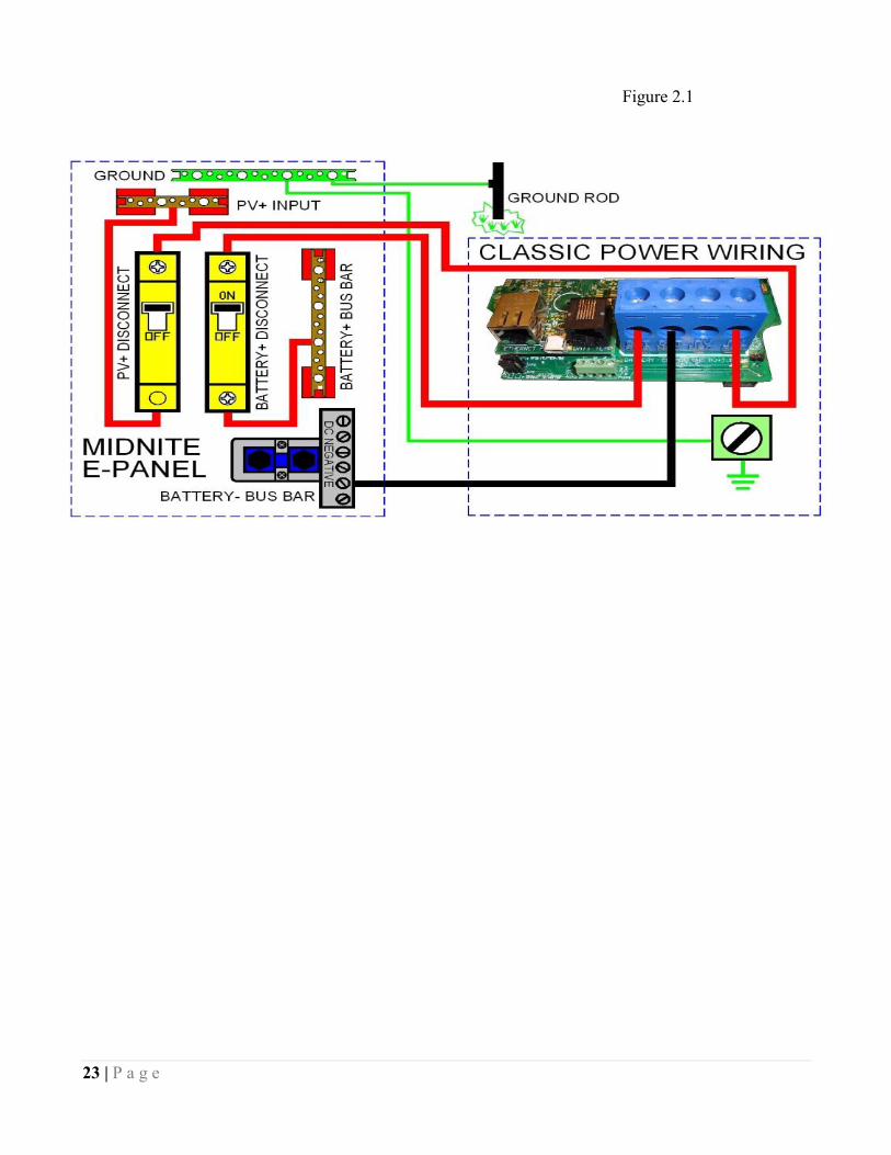
23 | P a g e
Figure 2.1
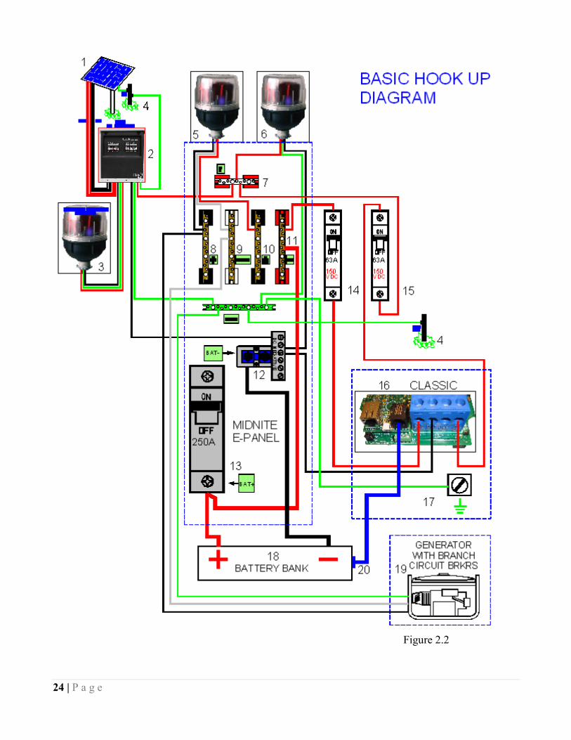
24 | P a g e
Figure 2.2

25 | P a g e
DC Terminal Connector
Figure 2.4
The Classic's DC terminal connector is located on the circuit board as shown in. The connector will
take up to a #4 AWG. #4 AWG THHN when installed in the Classic and MidNite E-Panel is rated for
over 100 amps and is therefore suitable for the highest power available from the Classic 150.
Over Current Protection and Wire Size Requirements
The over current devices, wiring, and installation methods used must conform to all electrical codes
applicable to the location of installation. Wiring needs to be protected with proper strain relief clamps
and or conduit. See page 75 for a breaker and wire size chart.
The network cables, USB cable, BTS cable and auxiliary input/output cables should run in a different
conduit to preserve their signal. When installing the Classic in a MidNite E-Panel, it is acceptable to
run all wiring through the same knockout hole. It is legal to run signal and power wires together as long
as all wiring is listed for the highest voltage to be encountered.
Current Rating
The Classic limits the output current based on the model you have.
The Classic current ratings are:
Classic 150 + 150 Lite - 96 amps maximum
Classic 200 + 200 Lite - 79 amps maximum
Classic 250 + 250 Lite - 62 amps maximum
Classic 250ks + 250ks Lite – 58 amps maximum

26 | P a g e
Over Current Protection
The Classic must have over current protection to protect wiring from over current events. A means of
disconnect must be installed on the DC in and DC out of the Classic. Consult your local codes to
determine over current ratings. The breaker between the battery bank and the Classic must conform to
UL489. The breaker between the DC source and the Classic must conform to UL1077 or UL489. The
NEC requires 1.56 times short circuit current for PV over current protection. This is reduced to 1.25
times when using a breaker rated for continuous duty. All MidNite Solar breakers are
hydraulic/magnetic and are rated for continuous duty. No de-rating is required for the output breaker
when using MidNite Solar breakers.
PV in particular will be capable of producing more current than its name plate rating in extreme
situations so the safe minimum wire size should be selected for the PV array maximum short circuit
current. Please consult PV manufacturer for specifications. The US National Electrical Code requires
1.56 times the PV short circuit current for wire size on the PV input. Output wire size follows the NEC
guidelines. Typical wire size for output is 6AWG for the Classic250 and 4AWG for the Classic200 and
150 but check all de-ratings for your wire type and installation method.
Long Distance Wire Runs
The Classic offers some unique opportunities if you are faced with longer than normal wire runs
between the DC source and the Classic. The Classic comes in 3 input voltage ranges letting you design
a DC source at a higher voltage if it is beneficial. For example let’s say you have a 300 ft run from a
PV array to the Classic you could wire for an open circuit voltage close to 250vdc accounting for the
coldest temperature you will encounter. This will allow you to run a smaller gauge wire than with a
lower voltage charge controller. The efficiency of a high voltage Classic is less than the lower voltage
versions, so you need to weigh the benefit. If this sounds too complicated use this rule of thumb in
selecting the proper Classic. PV runs up to 100 feet, use the Classic 150. Runs up to 180 feet, use the
Classic 200. Above 180 feet use the Classic 250.
If the wire size between the DC source and the Classic is larger than the Classic's DC terminal
connector you can use a splicer block or similar connector to reduce down to #4 AWG close to the
Classic. The MidNite E-Panels are supplied with a PV input busbar that accepts up to 2/0 wire.
Connecting the Classic to the Clipper
The connections between the Clipper and Classic are fairly basic. There is the DC – and + conductors
from the Clipper to the PV input on the Classic. There is also a smaller set of – and + conductors
connecting Auxiliary 2 to the PWM input on the Clipper. To program the Classic to work with the
Clipper the Aux 2 needs to be programmed. Follow the steps below to program this. (Note: see our
instructional videos at www.midnitesolar.com)
-Enter the Main menu and scroll to Aux and press Enter.
-Scroll to the right to highlight the text under Aux 2 and press the upper right soft key.
-Scroll up or down to find Clipper control and press the right soft key again
-On this screen we need to select AC or DC for the Clipper you have (DC is default)
-Press the right soft key again and here we need to set the absolute voltage we want the clipper to allow
-Press Enter to save this data and press Main Menu until you get back to the Aux 1 and Aux 2 screen
-Set the Text under Aux 2 to say Clipper Control and press Enter.
-Press Status to return to the home screen.
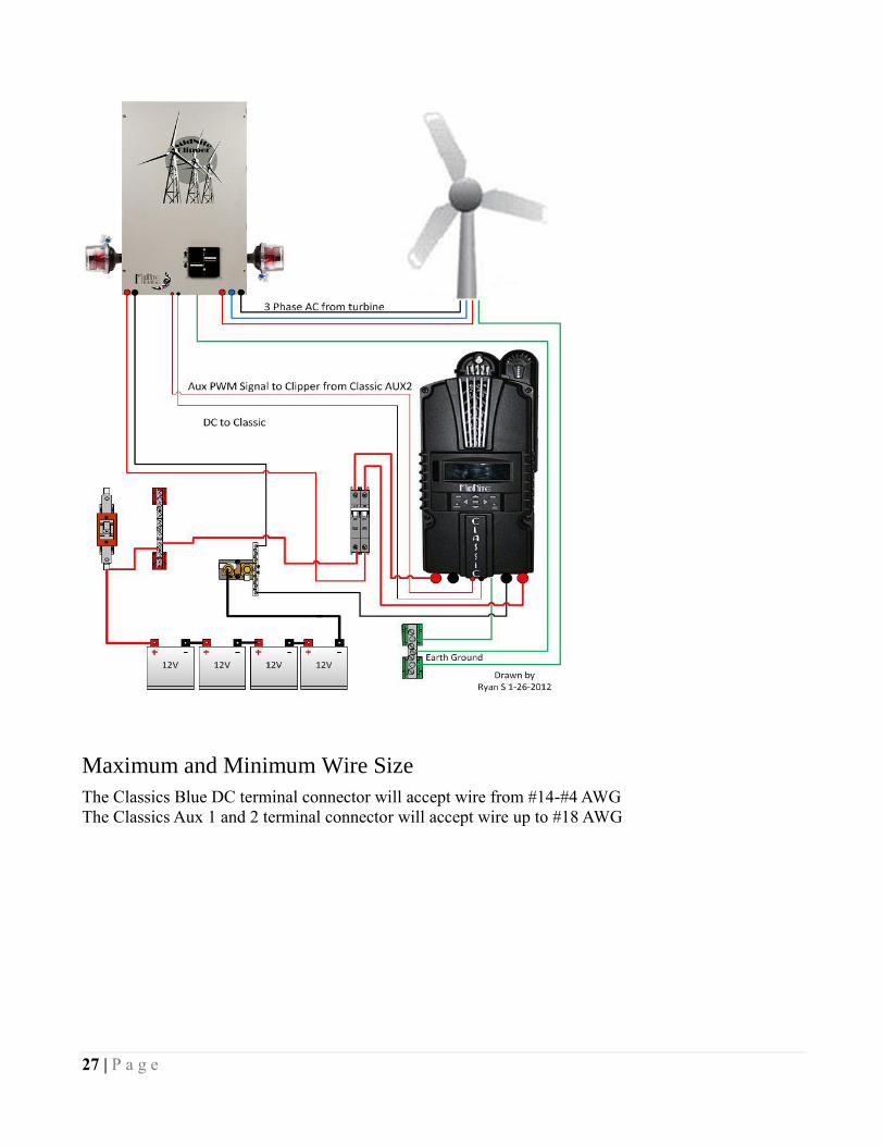
27 | P a g e
Maximum and Minimum Wire Size
The Classics Blue DC terminal connector will accept wire from #14-#4 AWG
The Classics Aux 1 and 2 terminal connector will accept wire up to #18 AWG
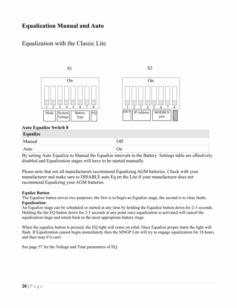
28 | P a g e
Equalization Manual and Auto
Equalization with the Classic Lite
Auto Equalize Switch 8
Equalize
Manual Off
Auto On
By setting Auto Equalize to Manual the Equalize intervals in the Battery Settings table are effectively
disabled and Equalization stages will have to be started manually.
Please note that not all manufacturers recommend Equalizing AGM batteries. Check with your
manufacturer and make sure to DISABLE auto Eq on the Lite if your manufacturer does not
recommend Equalizing your AGM batteries
Equlize Button
The Equalize button serves two purposes: the first is to begin an Equalize stage, the second is to clear faults.
Equalization:
An Equalize stage can be scheduled or started at any time by holding the Equalize button down for 2-3 seconds.
Holding the the EQ button down for 2-3 seconds at any point once equalization is activated will cancel the
equalization stage and return back to the most appropriate battery stage.
When the equalize button is pressed, the EQ light will come on solid. Once Equalize proper starts the light will
flash. If Equalization cannot begin immediately then the MNGP Lite will try to engage equalization for 18 hours
and then stop if it can't.
See page 57 for the Voltage and Time parameters of EQ.
S1 S2
Mode System
Voltage
Battery
Type EQ DHCP IP Address
MODBUS
port
1 2 3 4 5 6 7 8
On
1 2 3 4 5 6 7 8
On

29 | P a g e
Equalization with the standard Classic
30 | P a g e
Standard Classic programming
Commissioning the Classic (Quick Start)
The Classic will enter into the Quick Set screens upon initial power up. If the Classic does not enter
into the quick set or you want to restore to Factory Default follow these steps to get initiate a Quick
Set.
With the power off to the Classic Hold the left and right arrow buttons down.
Turn the power on to the Classic and continue to hold the arrow buttons until the setup screen is
displayed.
Answer the questions on the next few screens to complete the Quick Set.
Battery Charge Stages and Meanings
Bulk MPPT
This stage of the Classic means; that the Classic will be putting out as much current as it can to raise the
battery voltage to the absorb voltage set point. This is also known as constant current mode.
Absorb
This stage means that the Classic will maintain the absorb set point voltage until the batteries are charged.
This stage is terminated at the end of the Absorb time or the End Amps set point whichever is reached
first. At this stage the classic is not putting out maximum current, as that would increase the battery
voltage over the Absorb set point. This is also referred to as constant voltage mode.
The absorb time is proportional to the bulk time. (i.e. the time bulk takes to reach the absorb voltage.) The
battery it’s considered “full” at the end of the absorb charge cycle.
Float
A Float cycle follows after the Absorb cycle is completed; Float is displayed on the screen. Battery volt-
age is held at the float voltage set point.
Equalize
Equalization function can be manually initiated or can be set up to Auto Equalize, refer to page 27 for de-
tails on setting up EQ. The intent of an equalization charge is to bring all battery cells to an equal voltage
by a controller deliberate overcharge. The goal is to return each battery cell to its optimum condition
through a series of voltage controlled chemical reactions inside the batteries.
Resting
Resting will show when the Classic is not charging the batteries this is typically do to low light.

31 | P a g e
Mode is OFF
The Classic is unique, it has multiple charging algorithms for just about any DC input. Because we support such a
wide variety of DC inputs we have also added a software “ON” and “OFF” feature. This software “Switch” basical-
ly turns the relay off effectively disconnecting the input source so the Classic will not charge the battery. If you see
“Mode is Off” in the bottom right corner of the display then the Mode may have got turned off. To turn the mode
back “ON” push the Main Menu button several times until “Wizard” is highlighted. Scroll to the right until “Mode”
is highlighted and press “Enter”. On this screen “OFF” should be highlighted use the up or down arrow to change it
to “ON” and press “Enter”. Press the Status button once to return to the main status screen.
Note: This is the same menu you would use to change between Charging algorithms IE Solar, Hydro etc
Adjusting Absorb, Equalize and Float Voltages
Absorb, Equalize and Float voltages are fully adjustable. You will need to get the actual voltages from the
battery manufacturer. To adjust these voltages follow the steps below.
Press Main Menu to enter the Main Menu
Scroll right or left until Charge is highlighted and push the Enter button
Highlight Volts and press the Enter button
Use left and right arrows keys to highlight the set point voltage to adjust
Use up and down arrow keys to lower or raise the voltage
Press the Enter button to save the new voltages.
Current Limit The Classic has a current limit component which interacts with the temperature of the charge controller.
If the Classic is exposed to extremely hot ambient conditions the output current will be reduced
automatically to keep the charge controller safe, if the orange LED comes on, on the MNGP it means that
the Classic is in current limit mode. If you believe the Classic is not hot and the orange LED is on, most
likely the current limit set point is too low. To check this follow steps bellow.
Press Main Menu
Highlight the CHARGE menu and press the Enter Button
Scroll to LIMITS and press the Enter Button
Press the right arrow key to highlight “Out Amps” or “In Amps” column
Use the up and down arrow keys to change the current limit then press the Enter Button to save
this data
LED Modes and the “Blinking Red LED”
The Classic may have a Red Blinking LED on its display. This has no effect on the Classic and simply
shows it is communicating with the Display. New Classics ship with this disabled. Below we will explain
the different LED Modes. To change the LED Mode press the “Main Menu” button repeatedly until

32 | P a g e
“Wizard” is highlighted. Scroll to the right until “Misc” is highlighted and press “Enter”. Now scroll to
“LED-Mode” and press “Enter”. Here you can use the up and down arrows to select the mode you prefer.
After selecting the appropriate LED Mode press “Enter” to save this data to the Classic. Pressing “Status”
will now bring you back to the home screen.
-OFF – No LED activity no matter what
-Rick Mode – LED Activity for Errors and Warnings only. (Over current, Arc Fault Etc)
-Blinky – basically cycles all the LEDs in a Disco fashion (Useful for Partys)
-LED 1 – LED activity for Warnings and Errors as well as info. A green LED on the display indicates the
Classic is in Float. A yellow LED on the display indicates a warning (Over Temp, over current etc). A red
LED on the Display indicates an Error (Arc Fault etc). There is also 3 LEDS inside the Classic that can be
viewed through the upper vents. The red LED indicates Auxiliary 1 is active. The blue LED is not used at
this time and the yellow LED indicates Auxiliary 2 is active
Calibrating Battery and PV Voltage
To calibrate the Classic battery and PV voltage reading, you will need a Volt meter to check the actual
battery bank voltage or input PV voltage. Using the volt meter measure the voltage on the DC terminal
connector of the Classic (refer to Figure 2.4) compare this reading to the reading on the Status screen in
the Classic,(press Status if not in this screen) to adjust the reading of the Classic to the one in the volt
meter follow these steps:
Press Main Menu, scroll to TWEAKS and press Enter
Highlight VBatt and use the up and down arrow keys to match both of the readings
Press the Enter button to save
Note. Use the description below to help complete the calibration of the Classic voltages.
TWEAKS screen
Figure 2.7
Configuring DC Input Source
To select the Mode the Classic will run in, follow the steps below.
Push the Main Menu button.
Scroll left or right until Mode is highlighted and then push the Enter button.
Scroll to the right and highlight the current Mode than use the up and down arrows to set the
mode you want.
Take note of the Right soft key most modes have some set points that can be adjusted.
Press the Main Menu button until you get back to the Mode Menu
Set the ON/OFF to ON and press Enter
Battery voltage adjust
Battery voltage
offset
Displayed
battery voltage
Input voltage adjust
Input voltage
offset
Displayed Input
voltage

33 | P a g e
The following Modes will appear in this order in the MODE Menu.
Micro Hydro This mode is intended for use with hydro systems but can be used with other sources as well. When the
Classic first turns on after the input voltage goes above battery voltage, it will sweep from that open
circuit voltage down to battery voltage, finding the maximum power point voltage (MPP V). Then return
the input to that newly found voltage. After the original turn on sweep, the Classic will do mini sweeps at
user adjustable time intervals. If the time interval is set to 0, the Classic will not do any mini sweeps but
will stay on this first found MPP V until the user goes to the mode menu and turns it off and back on
again.
Micro Hydro mode sweeps slightly slower than Solar mode and has 2 user adjustable settings. Sweep
Interval is the time between mini-sweeps, in minutes, and sweeps around the present (i.e. the last found),
MPP Voltage. The range of this sweep is determined by the Sweep Depth user adjustment and is
expressed as a percentage of Watts that the sweep started from. For example, if in Micro Hydro mode,
the Classic was outputting 1000 Watts and the Sweep Depth percentage was set for 20%, (200 Watts), the
sweep will bring the input voltage DOWN until the output power drops down to 800 Watts, then will
sweep UP in voltage until the power drops again down to 800 Watts and then go back to the newly found
MPP Voltage, waiting for the next sweep.
Solar This is the default mode for PV systems and has a very fast sweep (typically1/2 second or less) that will
re-sweep at user adjustable sweep intervals, unless the Classic finds that it needs to do a sweep on its own
because of changing conditions. The timed sweep interval is user adjustable and is in units of
minutes. SOLAR mode is typically best for PV systems, especially if there is partial shading at times
during the day. The Classic will show a message of "PV SHADE" if it thinks the PV array is partially
shaded (if this feature is enabled).
SOLAR mode is best suited for shaded or un-shaded PV arrays that are at least one nominal voltage
above the battery voltage. For severe partial shading or PV arrays with nominal voltage equal to battery
voltage, you may also want to try Legacy P&O (Perturb and Observe) MPPT mode.
Legacy P&O Legacy P&O (Perturb and Observe) mode is a slow tracking mode similar to the Micro Hydro mode but
with the difference that it is slightly faster and will shut off if the power source goes off.
It has 2 settings that are user adjustable. Sweep Interval is the time between mini-sweeps, in minutes, and
sweeps around the present (i.e. the last found), MPP Voltage. The range of this sweep is determined by
the Sweep Depth user adjustment and is expressed as a percentage of Watts that the sweep started
from. For example, if in Legacy P&O mode, the Classic was outputting 500 Watts and the Sweep Depth
percentage was set for 10%, (50 Watts), the sweep will bring the input voltage DOWN until the output
power drops down to 450 Watts, then will sweep UP in voltage until the power drops again down to 450
Watts and then go back to the newly found MPP Voltage, waiting for the next sweep.

34 | P a g e
Wind Track This mode uses a power curve that is either built by the user or one of the pre-installed graphs. The power
curve consists of 16 set points that consist of output amperage and input voltage, allowing the user to
custom build a curve for their Wind turbine. Please refer to the Wind section of the manual for full details
on programming the curve as well as our video that will help in understanding how to adjust these curves
using the wind graph editor.
Dynamic This is typically used for PV (solar) input sources and tries to follow, on a slow dynamic basis, the
changing conditions of the input source. This mode has one user adjustment which is a forced sweep
perturb trigger interval for times when the input condition changes do not trigger a dynamic sweep. The
interval is in units of minutes.
U-Set VOC% This is a fully manual mode based on a percentage of VOC. The Classic will sweep based on the user set
time in minutes and then park at a user set % of the VOC the Classic found on that sweep. This mode is
useful for testing or constant voltage sources.
Note: Mode must be manually turned ON after changing the mode. To turn the Mode on highlight the
OFF under ON/OFF and switch it to ON. Press enter to save this change.
Configuring the Classic for Wind Input Source
Wind
If you selected “Wind” you will need to select a power curve from the list of pre-loaded curves or build
your own. To access the list of power curves follow the steps below.
Push the Main Menu button.
Scroll left or right until “Mode” is highlighted and push the Enter button.
Set the status to OFF and then use the right soft key to select “Graph”.
Using the left soft key select “MEM”. Now you can scroll up and down through the menu and select from
the curve that was designed for your turbine. Once you find the correct power curve use the right soft key
to select “RECALL”. Now push the Enter button to save this power curve to the Classics memory.
There are also 9 memory spaces for you to save a custom power curve. To build custom power curves
select a memory location between 1 and 9 and hit “RECALL”. Use the right and left arrow buttons to
scroll through the 16 steps in the custom curve. On each step you can set the amperage by using the up
and down buttons. When you have the power curve the way you want it select “MEM”. Use the up and
down buttons to select a location 1 through 9 to save it in and select “SAVE”. Now push the Enter button
to save it to the Classic's memory.
For more information consult the videos contained in this DVD as well as the MidNite Solar web site.
Classic-Wind-Graph-Editor-1.mpg
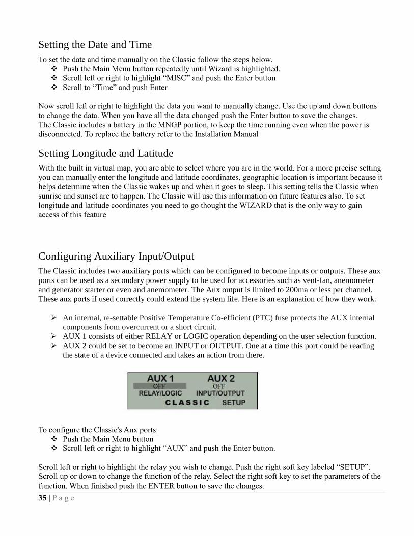
35 | P a g e
Setting the Date and Time
To set the date and time manually on the Classic follow the steps below.
Push the Main Menu button repeatedly until Wizard is highlighted.
Scroll left or right to highlight “MISC” and push the Enter button
Scroll to “Time” and push Enter
Now scroll left or right to highlight the data you want to manually change. Use the up and down buttons
to change the data. When you have all the data changed push the Enter button to save the changes.
The Classic includes a battery in the MNGP portion, to keep the time running even when the power is
disconnected. To replace the battery refer to the Installation Manual
Setting Longitude and Latitude
With the built in virtual map, you are able to select where you are in the world. For a more precise setting
you can manually enter the longitude and latitude coordinates, geographic location is important because it
helps determine when the Classic wakes up and when it goes to sleep. This setting tells the Classic when
sunrise and sunset are to happen. The Classic will use this information on future features also. To set
longitude and latitude coordinates you need to go thought the WIZARD that is the only way to gain
access of this feature
Configuring Auxiliary Input/Output
The Classic includes two auxiliary ports which can be configured to become inputs or outputs. These aux
ports can be used as a secondary power supply to be used for accessories such as vent-fan, anemometer
and generator starter or even and anemometer. The Aux output is limited to 200ma or less per channel.
These aux ports if used correctly could extend the system life. Here is an explanation of how they work.
An internal, re-settable Positive Temperature Co-efficient (PTC) fuse protects the AUX internal
components from overcurrent or a short circuit.
AUX 1 consists of either RELAY or LOGIC operation depending on the user selection function.
AUX 2 could be set to become an INPUT or OUTPUT. One at a time this port could be reading
the state of a device connected and takes an action from there.
To configure the Classic's Aux ports:
Push the Main Menu button
Scroll left or right to highlight “AUX” and push the Enter button.
Scroll left or right to highlight the relay you wish to change. Push the right soft key labeled “SETUP”.
Scroll up or down to change the function of the relay. Select the right soft key to set the parameters of the
function. When finished push the ENTER button to save the changes.

36 | P a g e
Main Aux Screen shows both Aux1 and Aux2 functions
Off - Places output to Low state (0 Volts)
Auto - Selects the assigned function to the Aux output or input
On - Sets output for Low state (12 Volts or Relay On)
The Following is a list of the Aux 1 and 2 functions with brief descriptions of their function.
Aux 1
Vent Fan Lo This mode will turn Aux 1 off above the voltage set point you program. It allows you to run a vent fan for
a battery bank based on battery voltage. There is a voltage set point that you set and Aux 1 will turn off
when the battery reaches that set point. The voltage has to fall 2 tenths of a volt below the set point for 30
seconds before Aux 1 will turn back on.
Vent Fan High This mode will turn Aux 1 on above the voltage set point you program. It allows you to run a vent fan for
a battery bank based on battery voltage. There is a voltage set point that you set and Aux 1 will turn on
when the battery reaches that set point. The voltage has to fall 2 tenths of a volt below the set point for 30
seconds before Aux 1 will turn off.
Float Low This mode will turn Aux 1 off whenever the Classic is in Float. Aux 1 will stay off until the Classic falls 3
tenths of a volt below the float voltage set point.
Float High This mode will turn Aux 1 on whenever the Classic is in Float. Aux 1 will stay on until the Classic falls 3
tenths of a volt below the float voltage set point.
Clipper Control This mode was intended to control the MidNite Clipper. It will send out a PWM signal whenever the
controller is unloading the turbine because the battery is full or close to it. There are no adjustment in this
mode the Classic is preprogrammed with the best parameters to control turbine RPM.
Day Light This mode will turn Aux 1 on at sunrise and turn it off at sunset based on the PV input voltage.
Table 2.0

37 | P a g e
Nite Light This mode will turn Aux 1 on at sunset and turn it off at sunrise based on the pv input voltage.
Toggle Test This mode will cycle Aux 1 for 1 second off and 1 second on repeatedly. This mode is mostly for testing
purposes.
Pv V on Low This Mode will turn Aux 1 off above a user set voltage based on the input voltage to the Classic ( V High)
and turn Aux 1 on when it hits a low voltage set point (V Low). It also allows you to set a delay time in
seconds the Classic will wait before turning Aux 1 off after reaching the V High set point. It also allows
you to set a hold time in seconds the Classic will wait before turning Aux 1 on after reaching the V Low
set point. This mode can be useful for controlling a failsafe stopping system for Hydro or Wind.
Pv V on High This Mode will turn Aux 1 on above a user set voltage based on the input voltage to the Classic ( V High)
and turn Aux 1 off when it hits a low voltage set point (V Low). It also allows you to set a delay time in
seconds the Classic will wait before turning Aux 1 on after reaching the V High set point. It also allows
you to set a hold time in seconds the Classic will wait before turning Aux 1 off after reaching the V Low
set point. This mode can be useful for controlling a failsafe stopping system for Hydro or Wind.
Opportunity Lo This mode will turn Aux 1 off when the Classic gets within a certain range of the voltage set points for
each charging stage (V High) and turn Aux 1 on when it gets to a low set point (V Low). These set points
are user adjustable and will allow the Absorb, Float and EQ timers to continue to run. You will adjust
these set points to negative numbers and the numbers are an offset from the voltage set point. For
example a -.2 would turn Aux 1 off 2 tenths of a volt below your set points. This mode will allow you
maximum diversion while maintaining your 3 stage charging. It also allows you to set a delay time in
seconds the Classic will wait before turning Aux 1 off after reaching the V High set point. It also allows
you to set a hold time in seconds the Classic will wait before turning Aux 1 on after reaching the V Low
set point.
Opportunity Hi This mode will turn Aux 1 on when the Classic gets within a certain range of the voltage set points for
each charging stage (V High) and turn Aux 1 off when it gets to a low set point (V Low). These set points
are user adjustable and will allow the Absorb, Float and EQ timers to continue to run. You will adjust
these set points to negative numbers and the numbers are an offset from the voltage set point. For
example a -.2 would turn Aux 1 on 2 tenths of a volt below your set points. This mode will allow you
maximum diversion while maintaining your 3 stage charging. It also allows you to set a delay time in
seconds the Classic will wait before turning Aux 1 on after reaching the V High set point. It also allows
you to set a hold time in seconds the Classic will wait before turning Aux 1 off after reaching the V Low
set point.
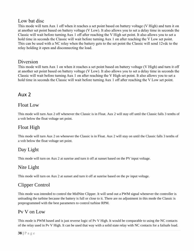
38 | P a g e
Low bat disc This mode will turn Aux 1 off when it reaches a set point based on battery voltage (V High) and turn it on
at another set point based on battery voltage (V Low). It also allows you to set a delay time in seconds the
Classic will wait before turning Aux 1 off after reaching the V High set point. It also allows you to set a
hold time in seconds the Classic will wait before turning Aux 1 on after reaching the V Low set point.
This can be used with a NC relay when the battery gets to the set point the Classic will send 12vdc to the
relay holding it open and disconnecting the load.
Diversion This mode will turn Aux 1 on when it reaches a set point based on battery voltage (V High) and turn it off
at another set point based on battery voltage (V Low). It also allows you to set a delay time in seconds the
Classic will wait before turning Aux 1 on after reaching the V High set point. It also allows you to set a
hold time in seconds the Classic will wait before turning Aux 1 off after reaching the V Low set point.
Aux 2
Float Low
This mode will turn Aux 2 off whenever the Classic is in Float. Aux 2 will stay off until the Classic falls 3 tenths of
a volt below the float voltage set point.
Float High
This mode will turn Aux 2 on whenever the Classic is in Float. Aux 2 will stay on until the Classic falls 3 tenths of
a volt below the float voltage set point.
Day Light
This mode will turn on Aux 2 at sunrise and turn it off at sunset based on the PV input voltage.
Nite Light
This mode will turn on Aux 2 at sunset and turn it off at sunrise based on the pv input voltage.
Clipper Control
This mode was intended to control the MidNite Clipper. It will send out a PWM signal whenever the controller is
unloading the turbine because the battery is full or close to it. There are no adjustment in this mode the Classic is
preprogrammed with the best parameters to control turbine RPM.
Pv V on Low
This mode is PWM based and is just reverse logic of Pv V High. It would be comparable to using the NC contacts
of the relay used in Pv V High. It can be used that way with a solid state relay with NC contacts for a failsafe load.

39 | P a g e
Pv V on High
This mode is PWM based and will PWM Aux 2 above a user set voltage (V High) based on the input voltage to the
Classic and stop when it hits a low voltage set point (V Low).
Toggle Test
This mode will cycle Aux 2 for 1 second off and 1 second on repeatedly. This mode is mostly for testing purposes.
Opportunity Lo
This mode is PWM based and is just reverse logic of Opportunity Hi. It would be comparable to using the NC con-
tacts of the relay used in Opportunity Hi. It can be used that way with a solid state relay and NC contacts to do di-
version above a set voltage.
Opportunity Hi
This mode is PWM based and will PWM Aux 2 when the Classic gets within a certain range of the voltage set
points for each charging stage (V High) and stop when it gets to a low set point (V Low). These set points are user
adjustable and will allow the Absorb, Float and EQ timers to continue to run. You will adjust these set points to
negative numbers and the numbers are an offset from the voltage set point. For example a -.2 would turn Aux 2 on
2 tenths of a volt below your set points. This mode will allow you maximum diversion while maintaining your 3
stage charging.
Diversion Lo
This mode is PWM based and is just reverse logic of Diversion Hi. It would be comparable to using the NC con-
tacts of the relay used in Diversion Hi. It can be used that way with a solid state relay and NC contacts to do diver-
sion above a set voltage.
Diversion Hi
This mode is PWM based and will PWM Aux 2 at a set point based on battery voltage (V High) and stop it at an-
other set point based on battery voltage (V Low).
Aux 1 Function
OUTPUT = Relay or 12V/0V Signal jumper selectable
Aux 1 has the relay so Diversion functions must operate slowly
VENT FAN LOW Aux1 on below setpoint
VENT FAN HIGH Aux1 on above setpoint
FLOAT LOW Aux1 off when in Float
FLOAT HIGH Aux1 on when in Float
CLIPPER CONTROL PWM Control for Cipper
DAY LIGHT Aux1 on at dawn off at dusk

40 | P a g e
NITE LIGHT Aux1 on at dusk off at dawn
TOGGLE TEST Aux1 cycled 1 sec interval
Pv V ON LOW Aux1 on below Pv in setpoint
Pv V ON HIGH Aux1 on above Pv in setpoint
OPPORTUNITY LO Divrt based on chrg state lo
OPPURTUNITY HI Divrt based on chrg state hi
LOW BAT DISC Disc load based on bat volt
DIVERSION Slow Diversion control
Aux 2 Function. Output/Input
OUTPUT = 12V/0V Signal
FLOAT LOW Aux2 off when in Float
FLOAT HIGH Aux2 on when in Float
DAY LIGHT Aux2 on at dawn off at dusk
NITE LIGHT Aux2 on at dusk off at dawn
CLIPPER CONTROL PWM Control for Clipper
Pv V ON LOW PWM sig below Pv in setpoint
Pv V ON HIGH PWM sig above Pv in setpoint
TOGGLE TEST Aux2 cycled 1 sec interval
OPPORTUNITY LO PWM divert rltv chg state lo
OPPORTUNITY HI PWM divert rltv chg state hi
DIVERSION LO PWM Divert on Bat voltage lo
DIVERSION HI PWM Divert on bat voltage hi
To set/ change threshold voltage as well as time do the following:
When in the function you wish to use press the right soft button
This will take you to the VOLTS menu here is where you set your threshold voltage
Use the left and right arrow keys to navigate through the options
Use the up and down arrow keys to raise or lower the threshold voltage
To change the time press again the right soft button to get to the TIME menu
In this menu do the same as you did in the VOLTS menu, until desired adjustments are made
Press ENTER to save
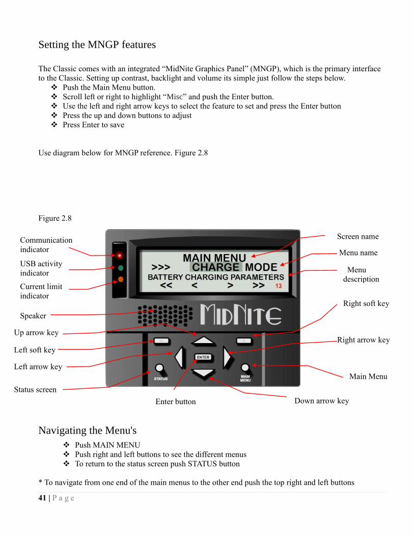
41 | P a g e
Setting the MNGP features
The Classic comes with an integrated “MidNite Graphics Panel” (MNGP), which is the primary interface
to the Classic. Setting up contrast, backlight and volume its simple just follow the steps below.
Push the Main Menu button.
Scroll left or right to highlight “Misc” and push the Enter button.
Use the left and right arrow keys to select the feature to set and press the Enter button
Press the up and down buttons to adjust
Press Enter to save
Use diagram below for MNGP reference. Figure 2.8
Figure 2.8
Navigating the Menu's
Push MAIN MENU
Push right and left buttons to see the different menus
To return to the status screen push STATUS button
* To navigate from one end of the main menus to the other end push the top right and left buttons
Down arrow key
Main Menu
Right arrow key
Right soft key
Up arrow key
Left soft key
Left arrow key
Status screen
Enter button
Current limit
indicator
Speaker
USB activity
indicator
Communication
indicator
Menu
description
Screen name
Menu name

42 | P a g e
Below the name of the menu is a description of the menu. Pushing the left and right buttons will enable
you to see all the main menus provided. Inside some of these main menus will be sub-menus to adjust the
parameters of the selected feature.
Here is an overview of these menus:
<<WIZARD— CHARGE —MODE—AUX—MISC—LOGS—TWEAKS—TEMPS—NET>>
Below each of the menu names is a row with a description of the menu inside. To enter a menu, the name
of the menu has to be highlighted. Pushing ENTER will show the submenus. The up and down arrow
keys are enabled for easier navigation. Highlighting a sub menu and pushing ENTER will take you inside
the submenu where you will be able to change the parameters of the unit. To get out of the submenus push
MAIN MENU, this will take you out of the submenus one at a time every time you push it. See page 44
for entire Menu Map.
Viewing Other MidNite Products on the Display
Coming Soon…….
Connecting Classic to Two MNGPs/Network cable
The Classic can be controlled with two MNGPs at the same time. This will help when the Classic is in a
shop and there is a considerable distance between the Classic and the controlling point (office, inside
house, garage etc.). Instead of going to the Classic to check status or to change a setting, the user can run
a cable to the controlling point and see the Classic in a second MNGP. The cable is a six wire phone
cable. Connect one side of the extension cable to the jack in the Classic labeled SLAVE/OUT and the
other end to the second MNGP. Since the Classic transmits power and data signals through the phone
cable to the MNGP the length of the cable is limited to 100ft.
MidNite Solar only offers a 3ft as an optional
accessory. If you are making your own cable
be sure be sure to insert cable end all the way
into the phone terminal to get a good contact.
Use the phone crimping pliers to crimp both
ends of the cable.
We recommend using flat phone cable for extension, just
because it is easier to work with. Use the two pictures above as reference. Make sure the color and
position of the wires are as shown in the diagram below. Use terminal connector tab as reference.
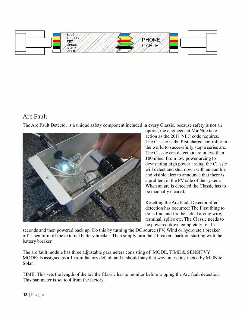
43 | P a g e
Arc Fault
The Arc Fault Detector is a unique safety component included in every Classic, because safety is not an
option, the engineers at MidNite take
action as the 2011 NEC code requires.
The Classic is the first charge controller in
the world to successfully stop a series arc.
The Classic can detect an arc in less than
100mSec. From low power arcing to
devastating high power arcing, the Classic
will detect and shut down with an audible
and visible alert to announce that there is
a problem in the PV side of the system.
When an arc is detected the Classic has to
be manually cleared.
Resetting the Arc Fault Detector after
detection has occurred: The First thing to
do is find and fix the actual arcing wire,
terminal, splice etc. The Classic needs to
be powered down completely for 15
seconds and then powered back up. Do this by turning the DC source (PV, Wind or hydro etc.) breaker
off. Then turn off the external battery breaker. Than simply turn the 2 breakers back on starting with the
battery breaker.
The arc fault module has three adjustable parameters consisting of: MODE, TIME & SENSITVY
MODE: Is assigned as a 1 from factory default and it should stay that way unless instructed by MidNite
Solar.
TIME: This sets the length of the arc the Classic has to monitor before tripping the Arc fault detection.
This parameter is set to 4 from the factory.

44 | P a g e
SENSITIVITY: This parameter determines how sensitive the Arc fault detector will be 1 being the most
sensitive and 15 the least. This parameter is set to 10 from the factory.
If you experience nuisance tripping you can raise the sensitivity one digit at a time. Follow the
instructions below to make adjustments or disable Arc fault. As a last resort, you may disable Arc fault if
your system cannot work with the arc fault detector.
To change the parameters of the Arc Fault, follow the steps below:
Press Main Menu
Scroll to the right or left until TWEAKS is highlighted and press ENTER
In TWEAKS press the right soft key to get to the BITS menu
In BITS press the right soft key to get to ARC ADJ
In this menu use the left and right keys to select the feature to adjust
Use the up and down arrow keys to change the parameters
In order for the Classic to read the new settings you must power cycle the Classic. Do this by turning the
DC source (PV, Wind or hydro etc.) breaker off. Then turn off the external battery breaker. Than simply
turn the 2 breakers back on starting with the battery breaker.
View Faults and Warning's
The Classic has some helpful safety features including the GFP (Ground Fault Protection) and AFD (Arc
Fault Detector). When one or more faults are detected the Classic will stop outputting power and display
a fault message in the bottom right corner of the home screen (STATUS).
View Logged Data
The Classic logs 380 days’ worth of data in its memory. The data logging in the Classic has two modes
and frequency of data capture.
DAILY HISTORY
Is captured once each day and is saved at night, after 2 hours of no activity when the PV input voltage is
below battery voltage for solar, or in modes that do not necessarily rest at night, like wind or hydro, the
capture will happen once every 24 hours. Data logged each day is kilo-watt-hours, Float time in hours and
minutes, the maximum power output for the day, maximum FET temperature inside the unit, maximum
PV or input voltage and maximum battery voltage for the day.
HOURLY HISTORY
Also referred to as “Short term History” is captured once every five 5 minutes anytime the Classic is not
resting (when it is charging). Data logged every 5 minutes is power, input voltage, battery voltage,
Charging Stage, amps out and kW-Hours.
A time and date stamp is associated with each data entry in both Daily and Hourly history logs. The main
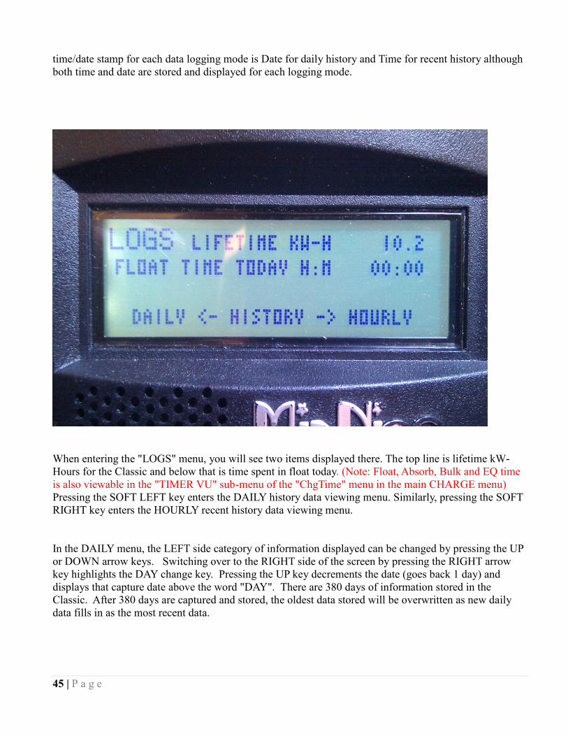
45 | P a g e
time/date stamp for each data logging mode is Date for daily history and Time for recent history although
both time and date are stored and displayed for each logging mode.
When entering the "LOGS" menu, you will see two items displayed there. The top line is lifetime kW-
Hours for the Classic and below that is time spent in float today. (Note: Float, Absorb, Bulk and EQ time
is also viewable in the "TIMER VU" sub-menu of the "ChgTime" menu in the main CHARGE menu)
Pressing the SOFT LEFT key enters the DAILY history data viewing menu. Similarly, pressing the SOFT
RIGHT key enters the HOURLY recent history data viewing menu.
In the DAILY menu, the LEFT side category of information displayed can be changed by pressing the UP
or DOWN arrow keys. Switching over to the RIGHT side of the screen by pressing the RIGHT arrow
key highlights the DAY change key. Pressing the UP key decrements the date (goes back 1 day) and
displays that capture date above the word "DAY". There are 380 days of information stored in the
Classic. After 380 days are captured and stored, the oldest data stored will be overwritten as new daily
data fills in as the most recent data.
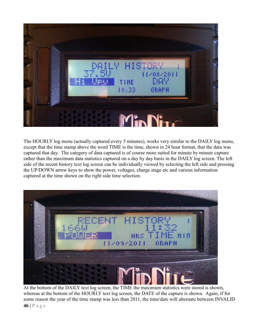
46 | P a g e
The HOURLY log menu (actually captured every 5 minutes), works very similar to the DAILY log menu,
except that the time stamp above the word TIME is the time, shown in 24 hour format, that the data was
captured that day. The category of data captured is of course more suited for minute by minute capture
rather than the maximum data statistics captured on a day by day basis in the DAILY log screen. The left
side of the recent history text log screen can be individually viewed by selecting the left side and pressing
the UP/DOWN arrow keys to show the power, voltages, charge stage etc and various information
captured at the time shown on the right side time selection.
At the bottom of the DAILY text log screen, the TIME the maximum statistics were stored is shown,
whereas at the bottom of the HOURLY text log screen, the DATE of the capture is shown. Again, if for
some reason the year of the time stamp was less than 2011, the time/date will alternate between INVALID

47 | P a g e
and the time/date stamped along with that data and does not necessarily mean the data itself is not correct.
If the data is all zeros and the year is shown as 2000, the data IS most likely invalid and not correct or the
logging memory has not been filled yet. This is why the Classic powers up with the year 05/04/2003... It
means that data was actually logged but the date was not set, whereas if it is showing 00/00/2000 it will
normally mean that the data is just zero and therefore invalid data as well as invalid time and date.
The upper right corner of the text log screens displays a number from 1 to 380. This number shows the
index or position of the data in the 380 data log time slots. The most recently stored data has an index of
1. Two data points ago shows an index of 2, etc. This index goes for either Daily History or Recent
History text log viewing screen.
Graphical Logging Display modes
Both DAILY and HOURLY logging can also be viewed in a graphical manner. While in the text viewing log
screen, pressing the Soft Right key labeled "GRAPH" will bring up this view screen. The HOURLY view is also
available in the main status cycle of screens, changed by repeatedly pressing the STATUS key, just after STATUS
TWO screen. This is labeled as "SHORT TERM HISTORY" in the STATUS screens.
A summary of the next Status screen will be shown while holding the status button before releasing it and entering
that next status screen. This also goes for the Recent History graph screen in Status.
Each data point shown in the graphical view screen is shown as a dot. There are a maximum of 96 dots, appearing
horizontally per screen with some information about each dot shown on the left side of the screen. An individual
data point can be selected for investigation by moving a small, flashing once per second vertical cursor horizontally
across the graphed data by using the Left and Right arrow keys. The most recent data is shown on the right most
side of the first screen. The cursor first appears around 20 dots or data points from the right side of the first screen.
(About 20 data points ago in history)
To scroll the data viewed one third of a screen to the left, hold the “Shift” key, the “Soft Left button”, down and tap
the “Left arrow key”. Each press of this combination of buttons will scroll the graphical view horizontally another
1/3 screen. Holding the Shift key and Right arrow key on the most recent data screen will push the cursor up
against the right side and onto data point one.
Pressing the Up arrow button will change the data viewed to the next category. For instance, in the Recent history
graph screen, the displayed data will change from Power to input voltage, battery voltage and kW-Hours. Pressing
the Down arrow key will bring the category of data back down again. A very brief 5 or 6 character annunciator dis-
played in the upper left corner tells us what category of data the graph is showing us. The number just below this 5
or 6 character descriptions is the actual number in volts or watts or applicable unit of data displayed at that cursor
position centered on the dot of the graph. The third line down on the left side of the recent data screen shows the
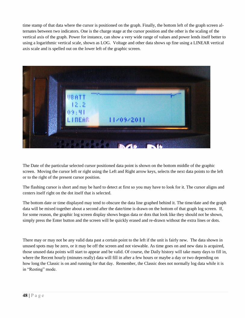
48 | P a g e
time stamp of that data where the cursor is positioned on the graph. Finally, the bottom left of the graph screen al-
ternates between two indicators. One is the charge stage at the cursor position and the other is the scaling of the
vertical axis of the graph. Power for instance, can show a very wide range of values and power lends itself better to
using a logarithmic vertical scale, shown as LOG. Voltage and other data shows up fine using a LINEAR vertical
axis scale and is spelled out on the lower left of the graphic screen.
The Date of the particular selected cursor positioned data point is shown on the bottom middle of the graphic
screen. Moving the cursor left or right using the Left and Right arrow keys, selects the next data points to the left
or to the right of the present cursor position.
The flashing cursor is short and may be hard to detect at first so you may have to look for it. The cursor aligns and
centers itself right on the dot itself that is selected.
The bottom date or time displayed may tend to obscure the data line graphed behind it. The time/date and the graph
data will be mixed together about a second after the date/time is drawn on the bottom of that graph log screen. If,
for some reason, the graphic log screen display shows bogus data or dots that look like they should not be shown,
simply press the Enter button and the screen will be quickly erased and re-drawn without the extra lines or dots.
There may or may not be any valid data past a certain point to the left if the unit is fairly new. The data shown in
unused spots may be zero, or it may be off the screen and not viewable. As time goes on and new data is acquired,
those unused data points will start to appear and be valid. Of course, the Daily history will take many days to fill in,
where the Recent hourly (minutes really) data will fill in after a few hours or maybe a day or two depending on
how long the Classic is on and running for that day. Remember, the Classic does not normally log data while it is
in “Resting” mode.

49 | P a g e
Dealer Information Screen
For dealers’ convenience the Classic has a display screen that can be modified to publicize the dealers’
business information. This is helpful because the customer will know who to contact in case they want to
report any problems regarding the product. This will also help to promote retailers’ accessories that are
compatible with the Classic. This screen is capable of 20 characters per row and four rows, for a total of
80 modifiable characters.
To modify this display screen, follow these steps:
Press main menu
Scroll to MISC and select it
On the following screen, select MNGP and press enter
On this screen select LOAD DEFAULTS press enter
On the password select 365 and press enter
Using the up and down keys will allow you to change the alphabet characters
Now scroll left and right to go to the next character block
Do this until your desired message is complete
Press enter to save on the classic memory
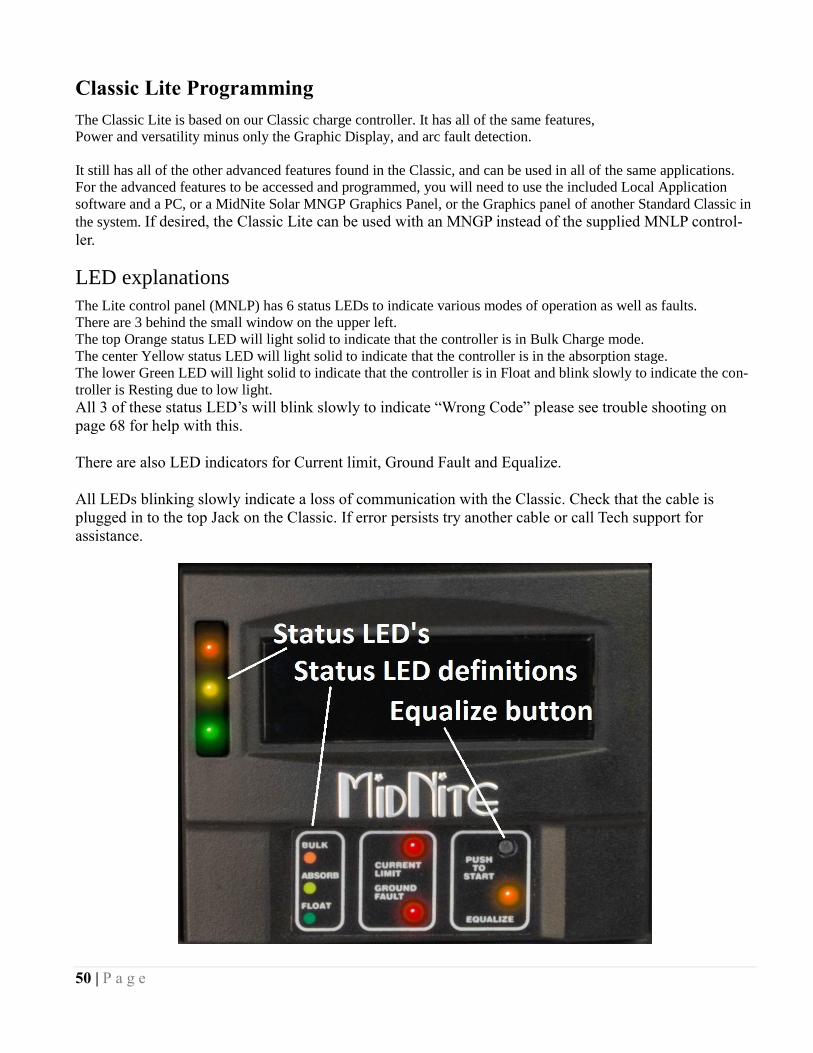
50 | P a g e
Classic Lite Programming
The Classic Lite is based on our Classic charge controller. It has all of the same features,
Power and versatility minus only the Graphic Display, and arc fault detection.
It still has all of the other advanced features found in the Classic, and can be used in all of the same applications.
For the advanced features to be accessed and programmed, you will need to use the included Local Application
software and a PC, or a MidNite Solar MNGP Graphics Panel, or the Graphics panel of another Standard Classic in
the system. If desired, the Classic Lite can be used with an MNGP instead of the supplied MNLP control-
ler.
LED explanations
The Lite control panel (MNLP) has 6 status LEDs to indicate various modes of operation as well as faults.
There are 3 behind the small window on the upper left.
The top Orange status LED will light solid to indicate that the controller is in Bulk Charge mode.
The center Yellow status LED will light solid to indicate that the controller is in the absorption stage.
The lower Green LED will light solid to indicate that the controller is in Float and blink slowly to indicate the con-
troller is Resting due to low light.
All 3 of these status LED’s will blink slowly to indicate “Wrong Code” please see trouble shooting on
page 68 for help with this.
There are also LED indicators for Current limit, Ground Fault and Equalize.
All LEDs blinking slowly indicate a loss of communication with the Classic. Check that the cable is
plugged in to the top Jack on the Classic. If error persists try another cable or call Tech support for
assistance.

51 | P a g e
Programming
There are four separate ways to program a Classic Lite.
1-The programming is done using Dip Switches under the front cover of the MNLP.
2-The Classic Lite can be programmed with an independent MNGP.
3-The Lite can be Networked with a standard Classic and programmed using the standard Classic’s
MNGP
4-The Classic Lite can be programmed using the Local App (Through the Ethernet connection) software
included on the DVD or available at www.midnitesolar.com
Dip Switches
Below you will find an Explanation of the Dip switches and the values associated with their settings. Up
is on and down is off on the switches. To access the Dip switches you need to remove the front cover on
the Lite display panel. Firmly grasp the left and right side of the cover and slide it off.

52 | P a g e
Now you will need to use the supplied tool (Toothpick) to place all 15 switches in the correct position. All
the information on the switches can be found on the labels on the MNLP as well as in the tables below.
Keep in mind if any of the switches are set to Custom the Lite display becomes a LED display only and
you will need to use the included PC software or a MNGP to program the Classic. Please see page XX in
the Appendix for info on using the “Local App” software in conjunction with a PC.
Note: The Classic Lite will need to be programed in “Custom Mode” for all applications other than Solar.

53 | P a g e
Section 1 Switch settings explained
Mode: Switches 1 and 2 (Section 1)
On Section 1, the first 2 Switches are used to select which Solar Mode will be used.
For “Solar” Mode: set switches 1 and 2 to OFF . This is the optimum setting for virtually all solar installations.
For “Legacy “ Mode: Set Switch 1 to OFF and Switch 2 to On.
Legacy Mode can be used in cases where the Open Circuit Voltage is close to the battery voltage. For example, a 22
volt open circuit array and a 12 volt battery. Or where there are mixed sizes of panels in an array. (Solar Salad)
When switch 1, 2, 3, and 4 are set to ON, the Lite is in “Custom Programming mode” and can be programmed
using any of the other 3 methods.
Custom set up will be required for Wind, Hydro, Fuel Cell applications as well as setting up the Aux. output
controls and for Battery voltages of 36, 60, and 72 (84, 96, 108, and 120 volt batteries for KS model)
System Voltage: Switches 3 and 4 (Section 1)
On Section 1, set Switches 3 and 4 to the appropriate positions (Found in the Chart) corresponding to your system's
battery voltage. 12, 24, and 48 volt systems are included in this menu. 36 and 72 volt battery set up can be
accomplished using the Custom set up method. (84, 96, 108, and 120 volt batteries for KS model)
Battery Type: Switches 5, 6, 7 (Section 1)
Switches 5, 6, and 7 allow you to select from 7 different battery types and charging profiles. These profiles can be
found in the 2 charts on the following pages. These should cover most common applications. If slightly different
voltages are desired, this can be done using Custom Mode and programming methods 2, 3, or 4.
Auto Equalize: Switch 8 (Section 1)
Switch 8 is used to select Automatic equalization.
In the OFF position, a manual equalization cycle, if desired, is selected by pressing the “Equalize”
button on the MNLP for 3 seconds. To Cancel Equalize, Press Equalize button for 3 seconds.
With Switch 8 in the ON position, the Lite will attempt to equalize the batteries automatically.
The equalize interval is dependent upon the battery type selected. Please refer to:
“Dip switch battery settings for 12, 24, or 48 volt batteries” for specific information on this function.
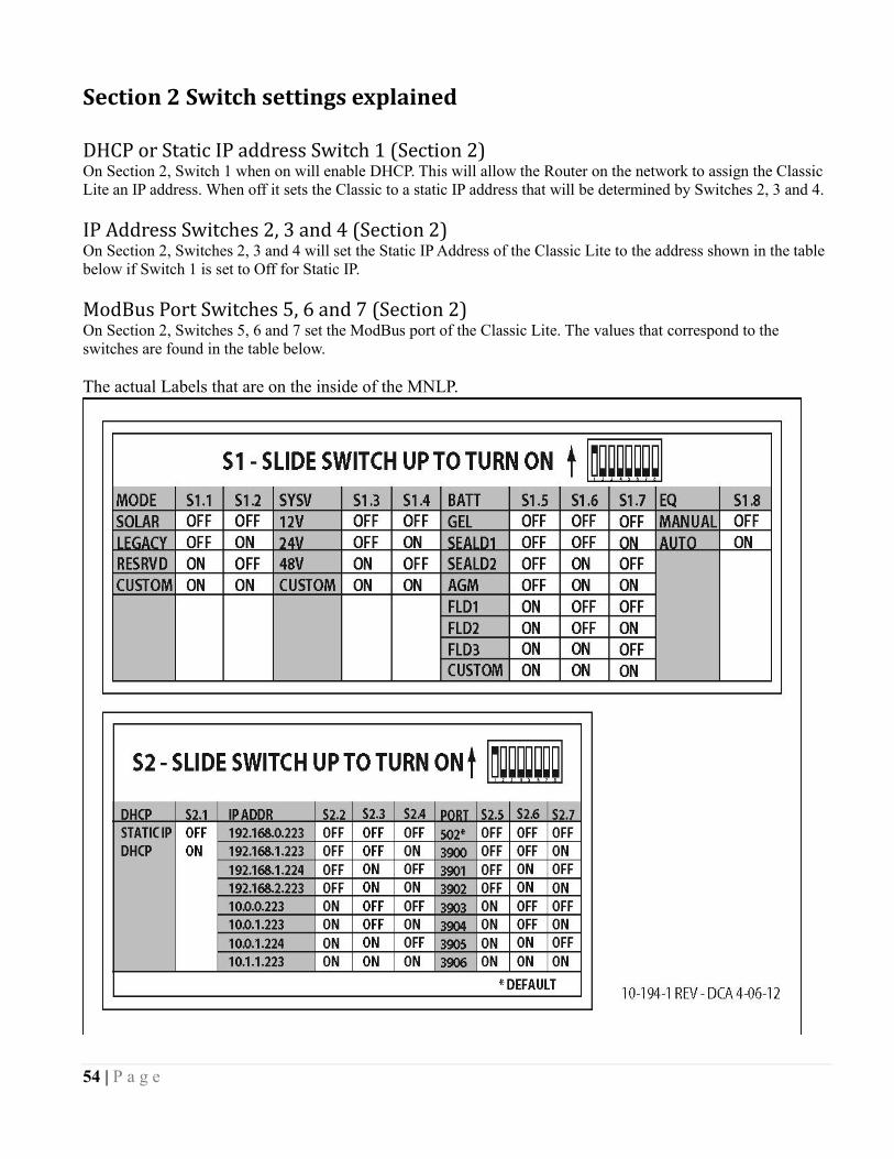
54 | P a g e
Section 2 Switch settings explained
DHCP or Static IP address Switch 1 (Section 2) On Section 2, Switch 1 when on will enable DHCP. This will allow the Router on the network to assign the Classic
Lite an IP address. When off it sets the Classic to a static IP address that will be determined by Switches 2, 3 and 4.
IP Address Switches 2, 3 and 4 (Section 2) On Section 2, Switches 2, 3 and 4 will set the Static IP Address of the Classic Lite to the address shown in the table
below if Switch 1 is set to Off for Static IP.
ModBus Port Switches 5, 6 and 7 (Section 2) On Section 2, Switches 5, 6 and 7 set the ModBus port of the Classic Lite. The values that correspond to the
switches are found in the table below.
The actual Labels that are on the inside of the MNLP.
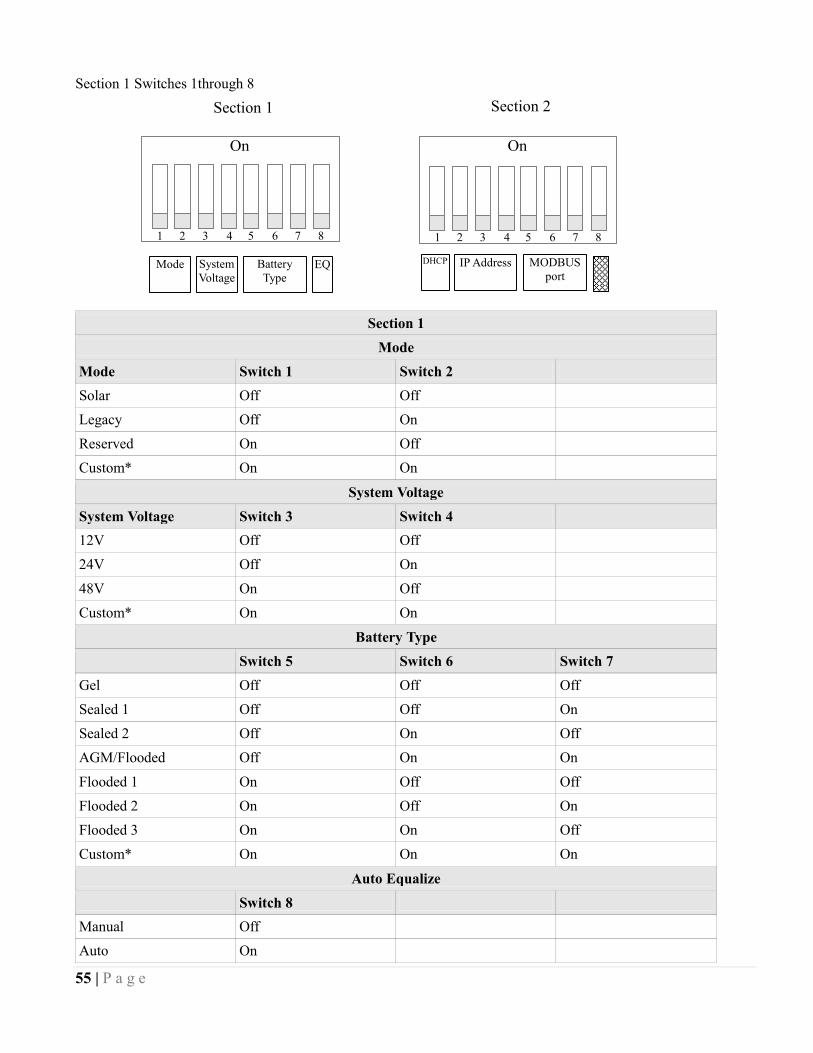
55 | P a g e
Section 1 Switches 1through 8
Section 1
Mode
Mode Switch 1 Switch 2
Solar Off Off
Legacy Off On
Reserved On Off
Custom* On On
System Voltage
System Voltage Switch 3 Switch 4
12V Off Off
24V Off On
48V On Off
Custom* On On
Battery Type
Switch 5 Switch 6 Switch 7
Gel Off Off Off
Sealed 1 Off Off On
Sealed 2 Off On Off
AGM/Flooded Off On On
Flooded 1 On Off Off
Flooded 2 On Off On
Flooded 3 On On Off
Custom* On On On
Auto Equalize
Switch 8
Manual Off
Auto On
Section 1 Section 2
Mode System
Voltage
Battery
Type EQ DHCP IP Address
MODBUS
port
1 2 3 4 5 6 7 8
On
1 2 3 4 5 6 7 8
On
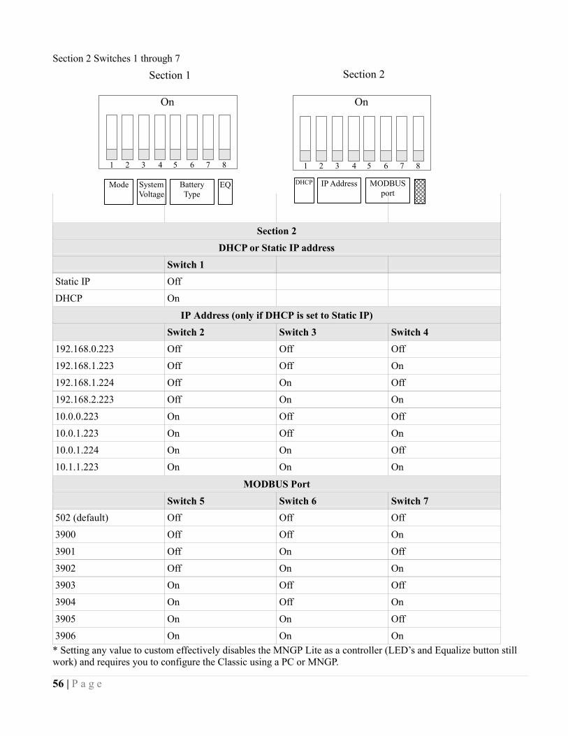
56 | P a g e
Section 2 Switches 1 through 7
Section 2
DHCP or Static IP address
Switch 1
Static IP Off
DHCP On
IP Address (only if DHCP is set to Static IP)
Switch 2 Switch 3 Switch 4
192.168.0.223 Off Off Off
192.168.1.223 Off Off On
192.168.1.224 Off On Off
192.168.2.223 Off On On
10.0.0.223 On Off Off
10.0.1.223 On Off On
10.0.1.224 On On Off
10.1.1.223 On On On
MODBUS Port
Switch 5 Switch 6 Switch 7
502 (default) Off Off Off
3900 Off Off On
3901 Off On Off
3902 Off On On
3903 On Off Off
3904 On Off On
3905 On On Off
3906 On On On
* Setting any value to custom effectively disables the MNGP Lite as a controller (LED’s and Equalize button still
work) and requires you to configure the Classic using a PC or MNGP.
Section 1 Section 2
Mode System
Voltage
Battery
Type EQ DHCP IP Address
MODBUS
port
1 2 3 4 5 6 7 8
On
1 2 3 4 5 6 7 8
On
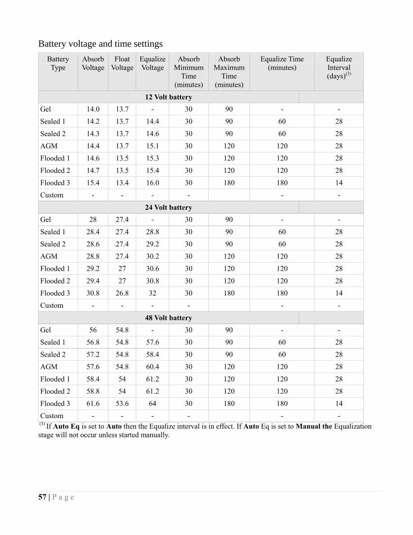
57 | P a g e
Battery voltage and time settings
Battery
Type
Absorb
Voltage
Float
Voltage
Equalize
Voltage
Absorb
Minimum
Time
(minutes)
Absorb
Maximum
Time
(minutes)
Equalize Time
(minutes)
Equalize
Interval
(days)(3)
12 Volt battery
Gel 14.0 13.7 - 30 90 - -
Sealed 1 14.2 13.7 14.4 30 90 60 28
Sealed 2 14.3 13.7 14.6 30 90 60 28
AGM 14.4 13.7 15.1 30 120 120 28
Flooded 1 14.6 13.5 15.3 30 120 120 28
Flooded 2 14.7 13.5 15.4 30 120 120 28
Flooded 3 15.4 13.4 16.0 30 180 180 14
Custom - - - - - -
24 Volt battery
Gel 28 27.4 - 30 90 - -
Sealed 1 28.4 27.4 28.8 30 90 60 28
Sealed 2 28.6 27.4 29.2 30 90 60 28
AGM 28.8 27.4 30.2 30 120 120 28
Flooded 1 29.2 27 30.6 30 120 120 28
Flooded 2 29.4 27 30.8 30 120 120 28
Flooded 3 30.8 26.8 32 30 180 180 14
Custom - - - - - -
48 Volt battery
Gel 56 54.8 - 30 90 - -
Sealed 1 56.8 54.8 57.6 30 90 60 28
Sealed 2 57.2 54.8 58.4 30 90 60 28
AGM 57.6 54.8 60.4 30 120 120 28
Flooded 1 58.4 54 61.2 30 120 120 28
Flooded 2 58.8 54 61.2 30 120 120 28
Flooded 3 61.6 53.6 64 30 180 180 14
Custom - - - - - - (3)
If Auto Eq is set to Auto then the Equalize interval is in effect. If Auto Eq is set to Manual the Equalization
stage will not occur unless started manually.

58 | P a g e
Using MNGP Remote to program a Classic Lite
The Classic Lite can be programmed using an MNGP remote. This is an easy way to get into and program not only
the basic functions, but the advanced features as well. In Dip Switch Section 1set DIP Switches 1, 2, 3, and 4 to
ON. This will tell the Classic Lite's MNLP display to allow custom programming, Next, remove the plug from the
back of the MNLP and plug it into the MNGP. Now, you basically have a Standard Classic. The programming for
this is found in the Standard Classic Manual. (Included on the DVD you got with your Lite) Once programmed in
this way, the MNGP can be removed, and the MNLP replaced. All functions, and voltages programed into the
Classic will now be retained in permanent memory.
Programming the Lite with a Networked Standard Classic
The third method of programming is to use a Standard Classic in the system to program the Lite in a simple
“Master / Slave” network. In Dip Switch Section 1set DIP Switches 1, 2, 3, and 4 to ON. This will tell the Lite’s
MNLP display to allow custom programming. Shown below is a set of jumpers. All Classics have these jumpers.
For proper operation, you will need to place the small black connector over both of the pins on the left most header,
as shown below. Do this to the Lite only.
The Lite can now be addressed by the MNGP on a networked Standard Classic. Networking is accomplished by
plugging one end of a (user supplied) 4 or 6 conductor phone cable into the “Slave” jack on the Standard Classic.
The other end of this 4 pin cable then plugs into the “Master” jack on the Lite. Use the provided blue cable to
connect the MNLP to the “Remote” jack of the Lite. Connected like this, the MNGP on the Standard Classic now
becomes not only the programmer, but also the digital Graphic display for the Lite. To access the Lite from the
Standard Classic's MNGP, hold down the Left arrow key, and tap the Up arrow. The display should now read
“CLASSIC 2” in the center of the screen. “Classic 2” represents the Lite. By holding the Left arrow, and using the
up and down arrows, you can select between the Standard “Classic” and the Lite “Classic2”
Note: There are currently over 100 possible “Addresses” in the MNGP that can be accessed by holding the left
arrow and tapping the up and down arrows. If you get “Lost” Just head up or down until you find your Classic
(Address 10) and Classic2 (Address 11)
Programming is now done the same as for the Standard Classic. Please see the Classic owner’s manual for more
information.

59 | P a g e
Programming the Lite with the Local App
Coming Soon
Clearing Faults
If either the Ground Fault or Current Limit fault light is lit, then the equalize button can be tapped to clear
these faults. If the fault condition has not been removed, however, then the light will re-illuminate
indicating that a fault condition is still present.
Notes on the Lite
If anything is set to Custom, then the MNGP lite will not send any programming data to the Classic. So a
Custom setting effectively disables MNGP Lite Control over the Classic requiring the user to use a PC or
MNGP to configure the Classic.
Note: The Custom setting still allows full function of the LED’s and the EQ button
Explanations of Solar and Legacy
Solar
This is the default mode for PV systems and has a very fast sweep (typically1/2 second or less) that will
re-sweep at user adjustable sweep intervals, unless the Classic finds that it needs to do a sweep on its own
because of changing conditions. The timed sweep interval is user adjustable and is in units of
minutes. SOLAR mode is typically best for PV systems, especially if there is partial shading at times
during the day. The Classic will show a message of "PV SHADE" if it thinks the PV array is partially
shaded (if this feature is enabled).
SOLAR mode is best suited for shaded or un-shaded PV arrays that are at least one nominal voltage
above the battery voltage. For severe partial shading or PV arrays with nominal voltage equal to battery
voltage, you may also want to try Legacy P&O (Perturb and Observe) MPPT mode.
Legacy P&O
Legacy P&O (Perturb and Observe) mode is a slow tracking mode similar to the Micro Hydro mode but
with the difference that it is slightly faster and optimized for Solar. Legacy mode can be very usefull for
arrays that experience heavy shading issues as well as PV arrays that have a low voltage. If the array has a
VOC (Open Circuit Voltage) of less than 125% of the battery voltage Solar mode will not work as well so
Legacy will be a better choice.

60 | P a g e
Uploading New Firmware to the Classic
The Classic has the ability to have its firmware updated with the included USB cable and a Windows
based PC. Please see www.midntesolar.com and click on the Firmware tab for the firmware and
instructions. Do to the various different Windows configurations we will not go into detail in the Classic
Manual. The Firmware upgrade is fail safe so if the wrong code is installed the Classic simply says
“Wrong code” prompting you to load the correct code. Also if the upload is interrupted for whatever
reason simply start over. WARNING ! The Classic's USB port is NOT isolated from battery negative. This is typically only an issue on positive ground systems
or systems with a tripped ground fault protection device. Care must be taken that a computer connected to the Classic's USB port is
either isolated from ground and the Classic's negative or that the computer's USB negative is common with the Classic's negative
and ground.
Prepare Classic charge controller for update.
1. Now go to your electrical panel and identify the input and output breakers for the Classic. Turn them off.
Wait 3 minutes for the Classic to de-energize.
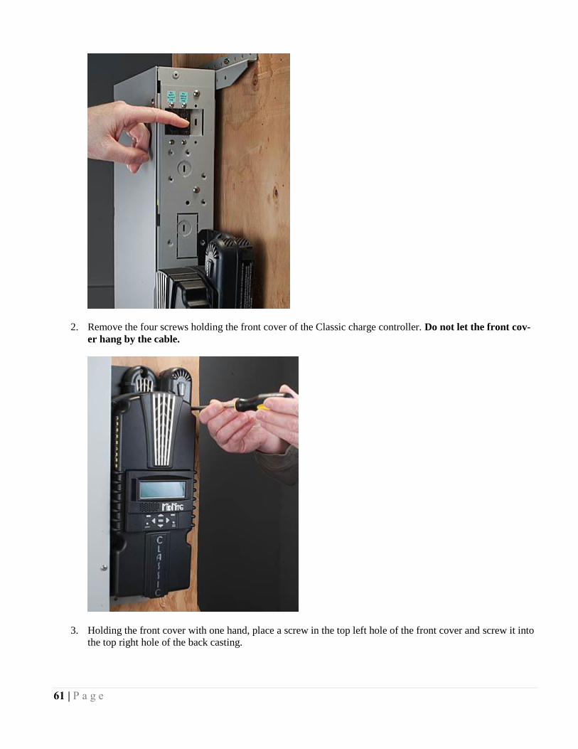
61 | P a g e
2. Remove the four screws holding the front cover of the Classic charge controller. Do not let the front cov-
er hang by the cable.
3. Holding the front cover with one hand, place a screw in the top left hole of the front cover and screw it into
the top right hole of the back casting.
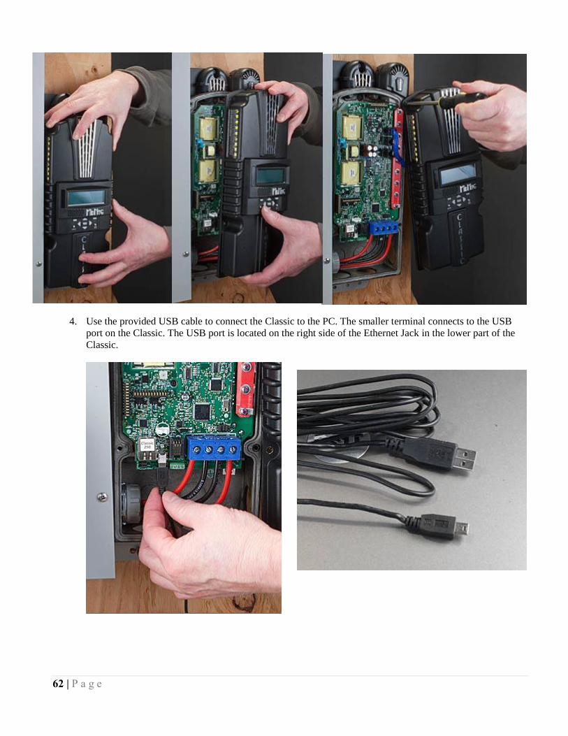
62 | P a g e
4. Use the provided USB cable to connect the Classic to the PC. The smaller terminal connects to the USB
port on the Classic. The USB port is located on the right side of the Ethernet Jack in the lower part of the
Classic.
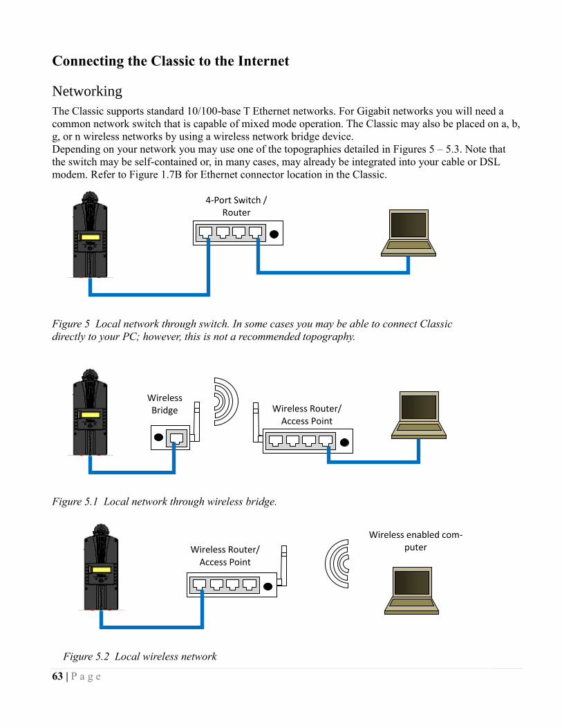
63 | P a g e
Connecting the Classic to the Internet
Networking
The Classic supports standard 10/100-base T Ethernet networks. For Gigabit networks you will need a
common network switch that is capable of mixed mode operation. The Classic may also be placed on a, b,
g, or n wireless networks by using a wireless network bridge device.
Depending on your network you may use one of the topographies detailed in Figures 5 – 5.3. Note that
the switch may be self-contained or, in many cases, may already be integrated into your cable or DSL
modem. Refer to Figure 1.7B for Ethernet connector location in the Classic.
4-Port Switch / Router
Figure 5 Local network through switch. In some cases you may be able to connect Classic
directly to your PC; however, this is not a recommended topography.
Wireless Router/ Access Point
Wireless Bridge
Figure 5.1 Local network through wireless bridge.
Wireless Router/ Access Point
Wireless enabled com-puter
Figure 5.2 Local wireless network
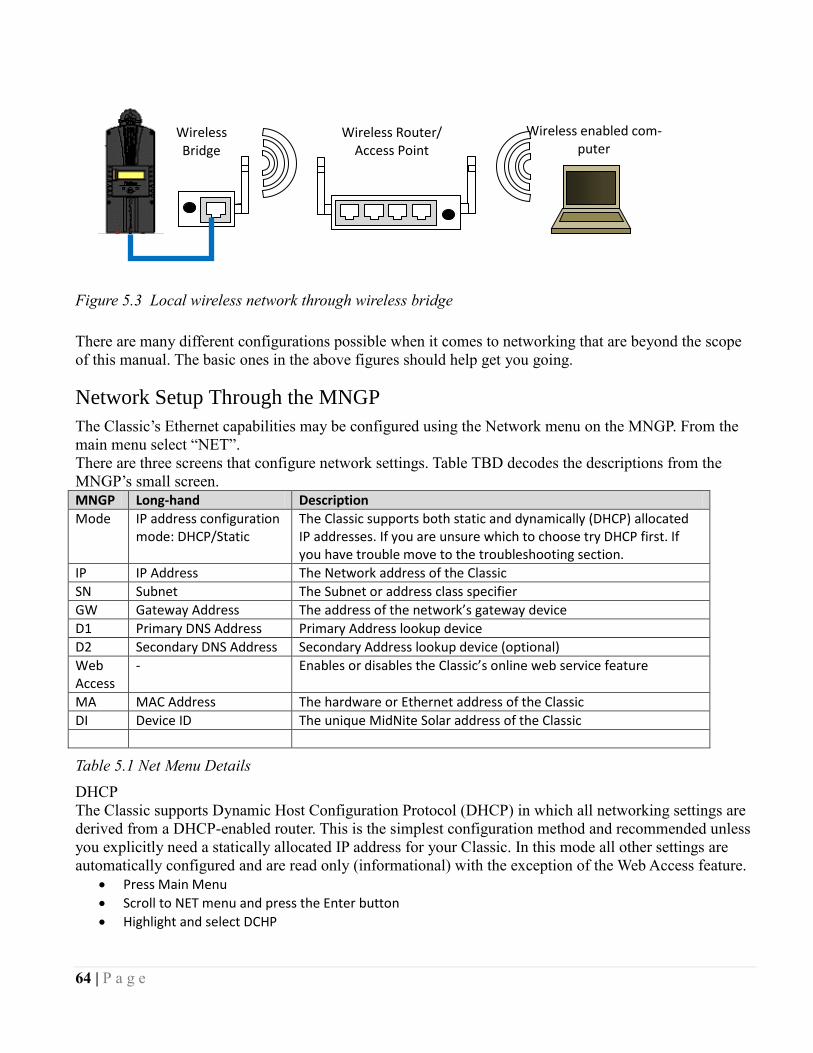
64 | P a g e
There are many different configurations possible when it comes to networking that are beyond the scope
of this manual. The basic ones in the above figures should help get you going.
Network Setup Through the MNGP
The Classic’s Ethernet capabilities may be configured using the Network menu on the MNGP. From the
main menu select “NET”.
There are three screens that configure network settings. Table TBD decodes the descriptions from the
MNGP’s small screen.
MNGP Long-hand Description
Mode IP address configuration mode: DHCP/Static
The Classic supports both static and dynamically (DHCP) allocated IP addresses. If you are unsure which to choose try DHCP first. If you have trouble move to the troubleshooting section.
IP IP Address The Network address of the Classic
SN Subnet The Subnet or address class specifier
GW Gateway Address The address of the network’s gateway device
D1 Primary DNS Address Primary Address lookup device
D2 Secondary DNS Address Secondary Address lookup device (optional)
Web Access
- Enables or disables the Classic’s online web service feature
MA MAC Address The hardware or Ethernet address of the Classic
DI Device ID The unique MidNite Solar address of the Classic
Table 5.1 Net Menu Details
DHCP
The Classic supports Dynamic Host Configuration Protocol (DHCP) in which all networking settings are
derived from a DHCP-enabled router. This is the simplest configuration method and recommended unless
you explicitly need a statically allocated IP address for your Classic. In this mode all other settings are
automatically configured and are read only (informational) with the exception of the Web Access feature.
Press Main Menu
Scroll to NET menu and press the Enter button
Highlight and select DCHP
Wireless enabled com-puter
Wireless Router/ Access Point
Wireless Bridge
Figure 5.3 Local wireless network through wireless bridge
65 | P a g e
Please note that the Classic’s DHCP protocol implementation usually takes a few seconds up to a minute
to update the network settings. If the network settings do not update within a minute, please consult the
troubleshooting section.
Static IP
The Classic supports static IP address allocation. In this mode you can assign the Classic a specific IP
address. This lets you set up things like port forwarding from your router or for networks with static IP
allocations.
Press Main Menu
Scroll to NET menu and press the Enter button
Highlight and select STATIC
Using the left and right keys, navigate to the settings to change and use the up and down arrows to adjust the desired fields.
Press the COMMIT softkey at any time to commit the settings to the Classic’s Flash memory.
Please note that static settings span two menu screens. You may use the soft keys to navigate between the
two menus. Pressing the ENTER key in either menu saves all settings to Flash memory.
For convenience when you manually set the device’s IP address the Gateway and Primary DNS addresses
follow the change. See the following sections for details on each of these fields.
IP Address
This is the local network address of your Classic. It usually takes the form “192.169.0/1.x” or “10.0.0.x”
depending on your networking equipment. You must be careful when selecting this address. If it does not
match your network subnet then the classic will not be able to communicate with the network. If it is the
same as another device on the network then collisions will occur causing both devices to act erratically.
Check your router settings or ask your network administrator which local address to use. Also refer to the
troubleshooting section for tips.
Subnet
This refers to the class of local network you are using. This depends on your network hardware but most
users should use “255.255.255.0” for this field.
Gateway
This is the address of your router or modem – the device which is connected directly to the Internet
proper. It will usually take the form 192.168.0/1.1 or 10.0.0.1 depending on your network configuration
and hardware. Check your router settings or ask your network administrator which local address to use.
Also refer to the troubleshooting section for tips.
DNS 1 & 2
The DNS is the means by which human-readable internet addresses are resolved to actual IP addresses on
the network. These values can usually be set identically to the gateway address depending on your
network hardware. If your ISP provides you with specific DNS servers then use those addresses in these
fields instead.
Example 1: Your gateway is a DSL modem with address 192.168.1.1. If your ISP has not given you
explicit DNS servers to use then set the D1 field to 192.168.1.1. D2 can be ignored.
Example 2: Your gateway is a cable modem with address 10.0.0.1. Your ISP has specified primary and
secondary DNS server addresses of 11.22.33.44 and 11.22.33.55, respectively. Set the D1 address to
11.22.33.44 and the D2 address to 11.22.33.55.
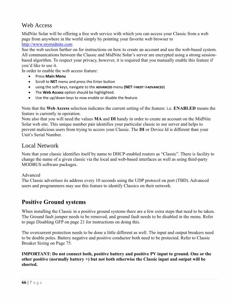
66 | P a g e
Web Access
MidNite Solar will be offering a free web service with which you can access your Classic from a web
page from anywhere in the world simply by pointing your favorite web browser to
http://www.mymidnite.com
See the web section further on for instructions on how to create an account and use the web-based system.
All communications between the Classic and MidNite Solar’s server are encrypted using a strong session-
based algorithm. To respect your privacy, however, it is required that you manually enable this feature if
you’d like to use it.
In order to enable the web access feature:
Press Main Menu
Scroll to NET menu and press the Enter button
using the soft keys, navigate to the ADVANCED menu (NET→NEXT→ADVANCED)
The Web Access option should be highlighted.
Use the up/down keys to now enable or disable the feature.
Note that the Web Access selection indicates the current setting of the feature: i.e. ENABLED means the
feature is currently in operation.
Note also that you will need the values MA and DI handy in order to create an account on the MidNite
Solar web site. This unique number pair identifies your particular classic to our server and helps to
prevent malicious users from trying to access your Classic. The DI or Device Id is different than your
Unit’s Serial Number.
Local Network
Note that your classic identifies itself by name to DHCP-enabled routers as “Classic”. There is facility to
change the name of a given classic via the local and web-based interfaces as well as using third-party
MODBUS software packages.
Advanced
The Classic advertises its address every 10 seconds using the UDP protocol on port (TBD). Advanced
users and programmers may use this feature to identify Classics on their network.
Positive Ground systems
When installing the Classic in a positive ground systems there are a few extra steps that need to be taken.
The Ground fault jumper needs to be removed, and ground fault needs to be disabled in the menu. Refer
to page Disabling GFP on page 21 for instructions on doing this.
The overcurrent protection needs to be done a little different as well. The input and output breakers need
to be double poles. Battery negative and positive conductor both need to be protected. Refer to Classic
Breaker Sizing on Page 75.
IMPORTANT: Do not connect both, positive battery and positive PV input to ground. One or the
other positive (normally battery +) but not both otherwise the Classic input and output will be
shorted.

67 | P a g e
HyperVOC ™
HyperVOC is a unique feature the Classic has built in. HyperVOC refers to; when the DC Input Voltage
raises above the maximum operating voltage (150V, 200V, 250V, depending on the Classic model).
HyperVOC gives you the flexibility to go up to the maximum operating voltage PLUS the nominal
battery voltage. For example, the Classic 150 has an input voltage rating of 150 operating volts, if the
Classic 150 is connected to a 48 volt battery bank, the HyperVOC voltage limit will be: 150V + 48V a
total of 198 Volts that the Classic can withstand without breaking. When the Classic input voltage rises
above 150 volts it will switch off (stop outputting power). As long as the Classic is in HyperVOC mode,
the microprocessor and all other functions like AUX will continue running. When the input voltage comes
back down below 150v (or the rated operating voltage of the Classic, depending on model) the Classic
will wake up and start charging again automatically. This could happen in a really cold morning with a
system that has a Voltage Open Circuit (VOC) close to the maximum operating input voltage.
Note 1. A HyperVOC message will be displayed on the bottom right side of the Status screen.
Note 2. Max nominal battery voltage to be added is 48v
HyperVOC can be useful in overcoming an industry shortcoming in charging 48 volt battery’s with
standard panels. For example let’s take a sample system with Solar World 165’s that have a VOC of
44.1vdc. The industry has limited us to 2 of these panels in series making it hard to charge a 48vdc battery
on hot summer days. With the Classic we designed in Hyper VOC to allow you to run 3 of these in series.
3 panels at 44.1vdc will give you a total VOC of 132.3vdc. When temperature compensated for cold
climates to 125% gives you 165vdc. This is above the maximum safe limits for most controllers but falls
well into the Hyper VOC range of the Classic. We do have to use Hyper VOC wisely though if we abuse
it the Controller will never wake up in colder weather.
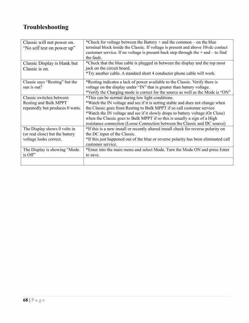
68 | P a g e
Troubleshooting
Classic will not power on.
“No self test on power up”
*Check for voltage between the Battery + and the common – on the blue
terminal block inside the Classic. If voltage is present and above 10vdc contact
customer service. If no voltage is present back step through the + and – to find
the fault. Classic Display is blank but
Classic is on.
*Check that the blue cable is plugged in between the display and the top most
jack on the circuit board.
*Try another cable. A standard short 4 conductor phone cable will work.
Classic says “Resting” but the
sun is out?
*Resting indicates a lack of power available to the Classic. Verify there is
voltage on the display under “IN” that is greater than battery voltage.
*Verify the Charging mode is correct for the source as well as the Mode is “ON”
Classic switches between
Resting and Bulk MPPT
repeatedly but produces 0 watts.
*This can be normal during low light conditions.
*Watch the IN voltage and see if it is setting stable and does not change when
the Classic goes from Resting to Bulk MPPT if so call customer service
*Watch the IN voltage and see if it slowly drops to battery voltage (Or Close)
when the Classic goes to Bulk MPPT if so this is usually a sign of a High
resistance connection (Loose Connection between the Classic and DC source)
The Display shows 0 volts in
(or real close) but the battery
voltage looks correct.
*If this is a new install or recently altered install check for reverse polarity on
the DC input of the Classic.
*If this just happened out of the blue or reverse polarity has been eliminated call
customer service.
The Display is showing “Mode
is Off”
*Enter into the main menu and select Mode. Turn the Mode ON and press Enter
to save.
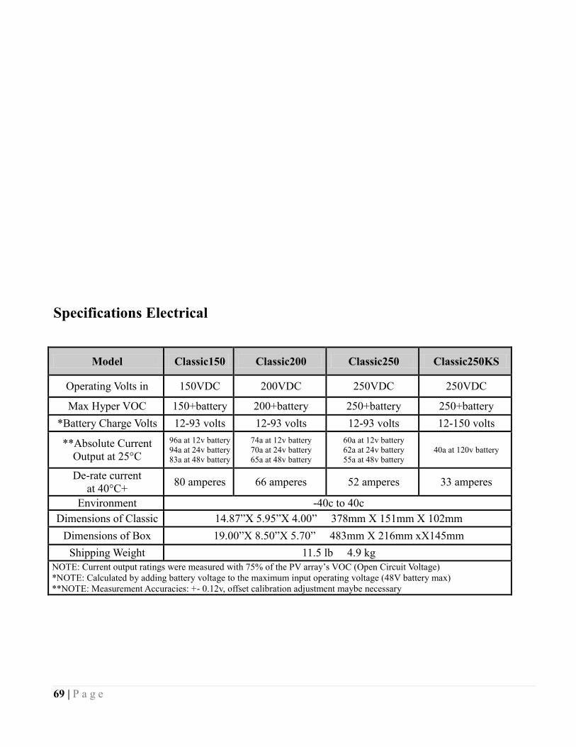
69 | P a g e
Specifications Electrical
Model Classic150 Classic200 Classic250 Classic250KS
Operating Volts in 150VDC 200VDC 250VDC 250VDC
Max Hyper VOC 150+battery 200+battery 250+battery 250+battery
*Battery Charge Volts 12-93 volts 12-93 volts 12-93 volts 12-150 volts
**Absolute Current
Output at 25°C
96a at 12v battery
94a at 24v battery
83a at 48v battery
74a at 12v battery
70a at 24v battery
65a at 48v battery
60a at 12v battery
62a at 24v battery
55a at 48v battery
40a at 120v battery
De-rate current
at 40°C+ 80 amperes 66 amperes 52 amperes 33 amperes
Environment -40c to 40c
Dimensions of Classic 14.87”X 5.95”X 4.00” 378mm X 151mm X 102mm
Dimensions of Box 19.00”X 8.50”X 5.70” 483mm X 216mm xX145mm
Shipping Weight 11.5 lb 4.9 kg
NOTE: Current output ratings were measured with 75% of the PV array’s VOC (Open Circuit Voltage)
*NOTE: Calculated by adding battery voltage to the maximum input operating voltage (48V battery max)
* **NOTE: Measurement Accuracies: +- 0.12v, offset calibration adjustment maybe necessary
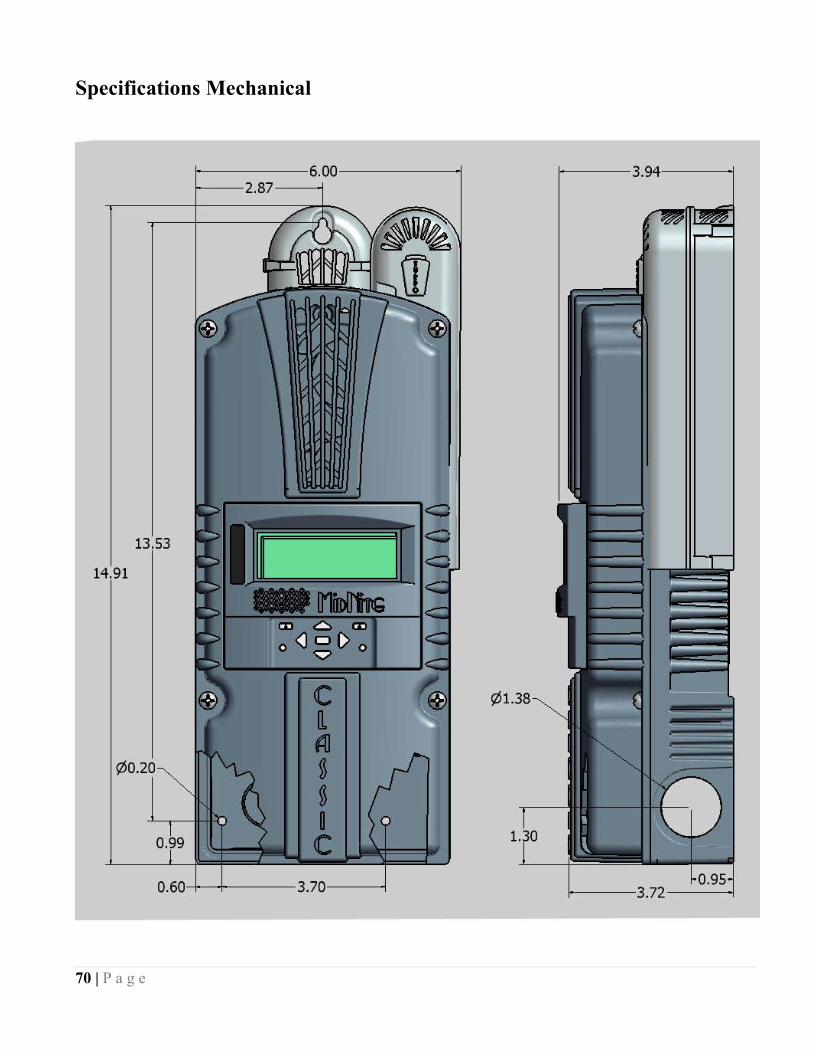
70 | P a g e
Specifications Mechanical
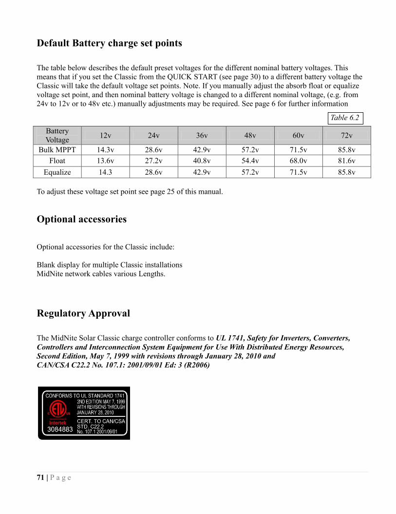
71 | P a g e
Default Battery charge set points
The table below describes the default preset voltages for the different nominal battery voltages. This
means that if you set the Classic from the QUICK START (see page 30) to a different battery voltage the
Classic will take the default voltage set points. Note. If you manually adjust the absorb float or equalize
voltage set point, and then nominal battery voltage is changed to a different nominal voltage, (e.g. from
24v to 12v or to 48v etc.) manually adjustments may be required. See page 6 for further information
Battery
Voltage 12v 24v 36v 48v 60v 72v
Bulk MPPT 14.3v 28.6v 42.9v 57.2v 71.5v 85.8v
Float 13.6v 27.2v 40.8v 54.4v 68.0v 81.6v
Equalize 14.3 28.6v 42.9v 57.2v 71.5v 85.8v
To adjust these voltage set point see page 25 of this manual.
Optional accessories
Optional accessories for the Classic include:
Blank display for multiple Classic installations
MidNite network cables various Lengths.
Regulatory Approval
The MidNite Solar Classic charge controller conforms to UL 1741, Safety for Inverters, Converters,
Controllers and Interconnection System Equipment for Use With Distributed Energy Resources,
Second Edition, May 7, 1999 with revisions through January 28, 2010 and
CAN/CSA C22.2 No. 107.1: 2001/09/01 Ed: 3 (R2006)
Table 6.2

72 | P a g e
Warranty
MidNite Solar's Classic comes with a standard 5 year warranty we will repair or replace the Classic at no
charge to the consumer during this 5 year period
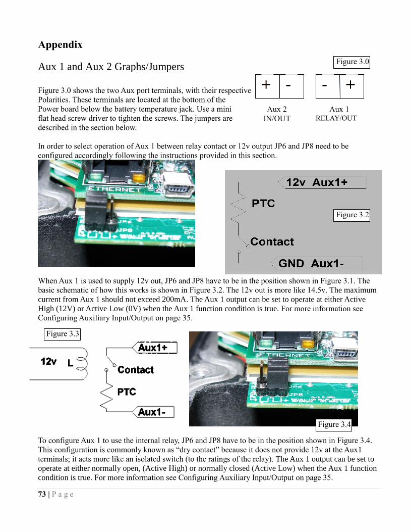
73 | P a g e
Aux 2
IN/OUT
- -
Aux 1 RELAY/OUT
Appendix
Aux 1 and Aux 2 Graphs/Jumpers
Figure 3.0 shows the two Aux port terminals, with their respective
Polarities. These terminals are located at the bottom of the
Power board below the battery temperature jack. Use a mini
flat head screw driver to tighten the screws. The jumpers are
described in the section below.
In order to select operation of Aux 1 between relay contact or 12v output JP6 and JP8 need to be
configured accordingly following the instructions provided in this section.
When Aux 1 is used to supply 12v out, JP6 and JP8 have to be in the position shown in Figure 3.1. The
basic schematic of how this works is shown in Figure 3.2. The 12v out is more like 14.5v. The maximum
current from Aux 1 should not exceed 200mA. The Aux 1 output can be set to operate at either Active
High (12V) or Active Low (0V) when the Aux 1 function condition is true. For more information see
Configuring Auxiliary Input/Output on page 35.
To configure Aux 1 to use the internal relay, JP6 and JP8 have to be in the position shown in Figure 3.4.
This configuration is commonly known as “dry contact” because it does not provide 12v at the Aux1
terminals; it acts more like an isolated switch (to the ratings of the relay). The Aux 1 output can be set to
operate at either normally open, (Active High) or normally closed (Active Low) when the Aux 1 function
condition is true. For more information see Configuring Auxiliary Input/Output on page 35.
Figure 3.2
Figure 3.3
Figure 3.4
Figure 3.0
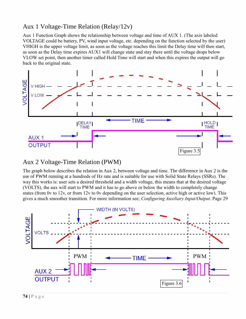
74 | P a g e
Aux 1 Voltage-Time Relation (Relay/12v)
Aux 1 Function Graph shows the relationship between voltage and time of AUX 1. (The axis labeled
VOLTAGE could be battery, PV, wind input voltage, etc. depending on the function selected by the user)
VHIGH is the upper voltage limit, as soon as the voltage reaches this limit the Delay time will then start,
as soon as the Delay time expires AUX1 will change state and stay there until the voltage drops below
VLOW set point, then another timer called Hold Time will start and when this expires the output will go
back to the original state.
Aux 2 Voltage-Time Relation (PWM)
The graph below describes the relation in Aux 2, between voltage and time. The difference in Aux 2 is the
use of PWM running at a hundreds of Hz rate and is suitable for use with Solid State Relays (SSRs). The
way this works is: user sets a desired threshold and a width voltage, this means that at the desired voltage
(VOLTS), the aux will start to PWM and it has to go above or below the width to completely change
states (from 0v to 12v, or from 12v to 0v depending on the user selection, active high or active low). This
gives a much smoother transition. For more information see; Configuring Auxiliary Input/Output. Page 29
PWM PWM
Figure 3.5
Figure 3.6
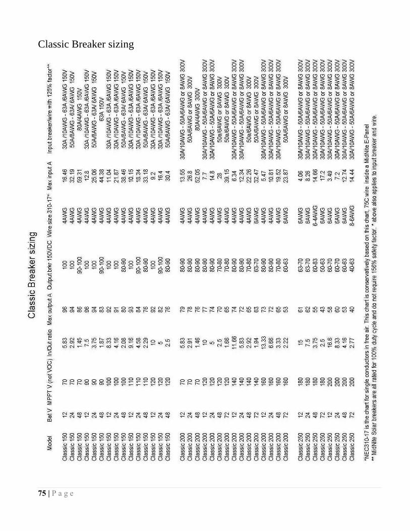
75 | P a g e
Classic Breaker sizing
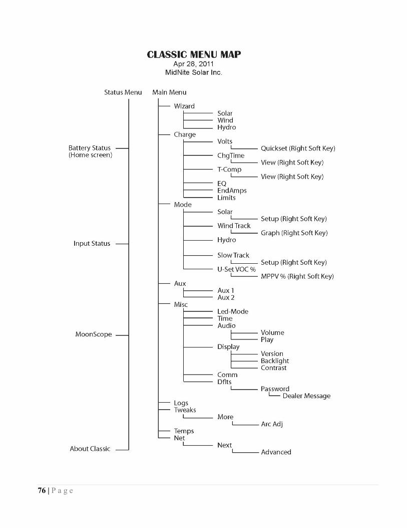
76 | P a g e

77 | P a g e
Label Set from Classic

78 | P a g e
MODBUS
DISCLAIMER
There is not a convention on the write-ability of registers. You may write to any register in the system
including registers THAT MAY DAMAGE OR DESTROY your Classic and attached equipment like
battery banks. Please make sure that you understand what you are doing before attempting to change any
settings (like battery voltage) using the raw MODBUS interface. MidNite Solar cannot take
responsibility for any damage to your Classic in the event of misconfiguration.
Registers and bits marked RESERVED are not necessarily unimplemented. Great care must be taken not
to overwrite these registers or bits to ensure proper operation of the Classic.
Wherever possible we have tried to indicate settings that may have an adverse effect on your system if set
incorrectly.
If you need to configure your system, please consider using the MNGP’s built in configuration wizard
which will step you through the process.
Conventions:
Register units are expressed using formulas to try to reduce the ambiguity surrounding converting from
the raw bus formats and human-readable values. Due to the nature of the Classic’s operation, there is not
a uniform convention as far as data endianness so you may find some classes of values that follow a Most
Significant Byte (MSB) first convention and others that use the Least Significant Byte (LSB) first
convention.
Bits are numbered from 0-15 in the little-endian or LSB-0 notation. That is, the least significant bit is
indexed by 0.
For Example, the number 43,981 is 0xABCD in hex is represented in binary as 1010101111001101.
The bit ordering is as shown in the following table: 15 14 13 12 11 10 9 8 7 6 5 4 3 2 1 0
1 0 1 0 1 0 1 1 1 1 0 0 1 1 0 1
So that the binary digit indexed by (0) is 1. (1) is 0, (6) is 1, and (10) is 0.
MODBUS registers are 16-bit (2-octet/byte) in size. When using values from the map to indicate
conversion formulas the following convention is used to access different octets:
Note that when talking about bytes or octets, it is more convenient to describe them in hexadecimal (base
16) form than in decimal. Some values are expressed in bytes as it is a more compact way of dealing with
certain classes of numbers (IP addresses, for example). We use the ‘C’ convention of referring to
hexadecimal numbers by prefixing them with ‘0x’. So the decimal value 10 is represented by the
hexadecimal value 0x0A.
A note on Read/Write: The Classic MODBUS does not strictly enforce the Read/Write accessibility of
some registers. It is possible to write to some registers marked Read Only. This will usually have no effect
on Classic operation, but in some cases you may corrupt a register from which you wanted to read data. In
some cases the registers are reset internally as new values. Additionally, some counters are accessible
directly. For example, the AbsorbTime (4139) timer is a “suggested” read only register; however, if your

79 | P a g e
MODBUS application has reason to reset or adjust this register, there is nothing to prevent you from
changing it however you please. Don’t be surprised if your batteries pop in and out of Absorb stage
unexpectedly, though!
Operators:
Indexing
[ ] square brackets around an address indicate the value of the register specified:
ex: [4116] indicates the value of the register at address 4116.
[ ]MSB Square brackets followed by an MSB means to use the most-significant byte of the register.
ex: if the value at register 4116 is 0x04B1 (decimal 1201):
[4116] = 0x04B1,
then
[4116]MSB = 0x04
[ ]LSB Square brackets followed by an LSB means to use the least-significant byte of the register.
ex: if the value at register 4116 is 0x04B1 (decimal 1201):
[4116] = 0x04B1,
then
[4116]LSB = 0xB1
( ) Parentheses refer to bits within the register.
For example: [4116](0) means “the 0th bit of the value in register 4116.
So if 4116 held the value 1 (0x0001 hex) then [4116](0) would be a 1. [4116](1…15)
would all be 0s.
… Ellipses represent ranges of values or indices.
For example to refer to the first three bits of a register you may see:
[4116](0…3) which signifies the first three bits of the value of register 4116.
You may also see spans of registers as:
[4116…4120] which refer to registers 4116 to 4120 inclusive.
Arithmetic
+ Add two numbers together
- Subtract two numbers (or negate the value on the right)
/ Divide two numbers (integer implied)
* Multiply two numbers (integer implied)
Logical

80 | P a g e
<< x Binary shift left. Shift the value x binary digits to the left. This is equivalent to multiplying
the decimal number by 2x. Ex:
[4116] = 0x0001
Then
[4116] << 1 = 0x0002.
>> x Binary shift right. Shift the value x binary digits to the right. This is equivalent to dividing
the decimal number by 2x.
[4116] = 0x0002
Then
[4116] >> 1 = 0x0001.
| OR two numbers together (aligned to LSB)
& AND two numbers together (aligned to LSB)
^ XOR two numbers together (aligned to LSB)
String
|| Concatenate.
[4116] = 0x4142.
[4116]MSB || [4116]LSB => 0x41 || 0x42 => ‘A’ ||‘B’ => “AB”
Examples:
Using the example of the Average PV Voltage register: dispavgVpv @ 4116
Suppose using a MODBUS scanner you retrieve the following (integer) value from the dispavgVpv
register at address 4116:
4116: 1201
The address itself: 4116
Full 16-bit value at the address: [4116] = 1201 (0x04B1 hex)
The top-most (MSB) octet of the register: [4116]MSB = 0x04 hex
The bottom-most (LSB) octet of the register [4116]LSB = 0xB1 hex
Applying the Conversion ([4116] / 10) Volts:
o [4116] = 1201
o 1201 / 10 = 120.1 Volts
File Transfer and Function Execution modes:
Coming soon (next revision of this document) will be information on how to use the MODBUS File
Transfer and Function execution commands. File Transfer will be necessary, for instance, to transfer
wind power curves to/from the Classic or logging and audio data to/from the Classic and/or MNGP.
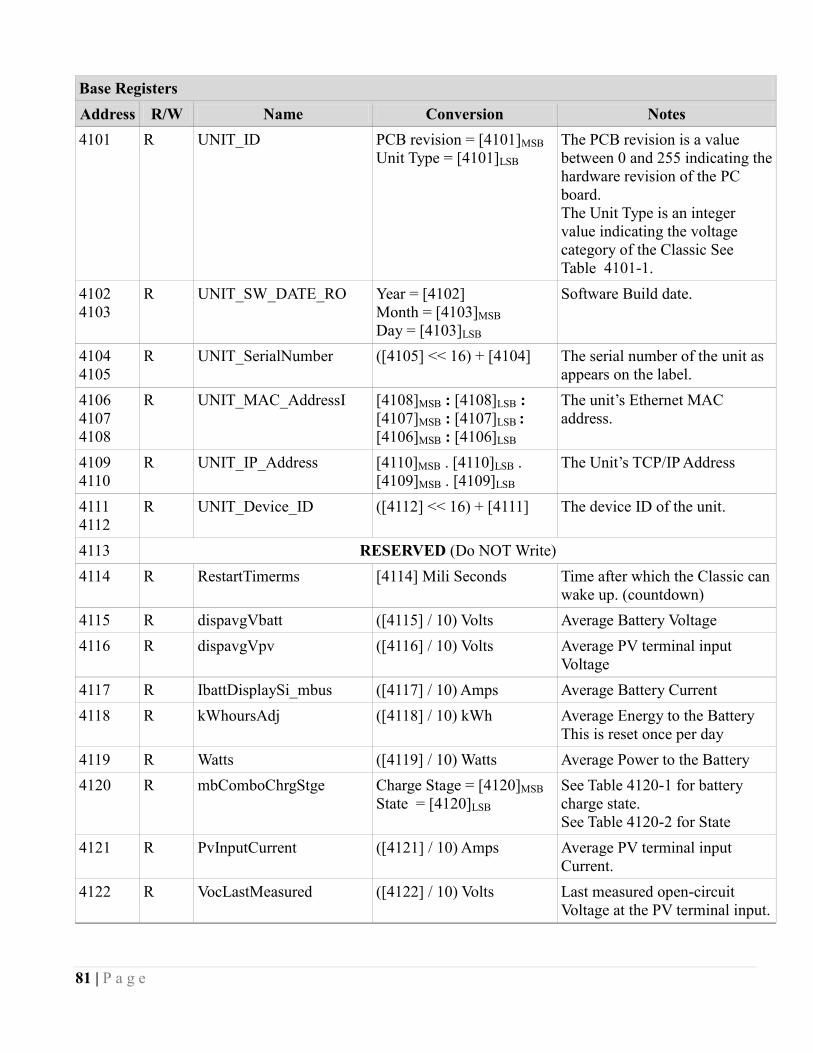
81 | P a g e
Base Registers
Address R/W Name Conversion Notes
4101 R UNIT_ID PCB revision = [4101]MSB
Unit Type = [4101]LSB
The PCB revision is a value
between 0 and 255 indicating the
hardware revision of the PC
board.
The Unit Type is an integer
value indicating the voltage
category of the Classic See
Table 4101-1.
4102
4103
R UNIT_SW_DATE_RO
Year = [4102]
Month = [4103]MSB
Day = [4103]LSB
Software Build date.
4104
4105
R UNIT_SerialNumber
([4105] << 16) + [4104] The serial number of the unit as
appears on the label.
4106
4107
4108
R UNIT_MAC_AddressI [4108]MSB : [4108]LSB :
[4107]MSB : [4107]LSB :
[4106]MSB : [4106]LSB
The unit’s Ethernet MAC
address.
4109
4110
R UNIT_IP_Address [4110]MSB . [4110]LSB .
[4109]MSB . [4109]LSB
The Unit’s TCP/IP Address
4111
4112
R UNIT_Device_ID ([4112] << 16) + [4111] The device ID of the unit.
4113 RESERVED (Do NOT Write)
4114 R RestartTimerms [4114] Mili Seconds Time after which the Classic can
wake up. (countdown)
4115 R dispavgVbatt ([4115] / 10) Volts Average Battery Voltage
4116 R dispavgVpv ([4116] / 10) Volts Average PV terminal input
Voltage
4117 R IbattDisplaySi_mbus ([4117] / 10) Amps Average Battery Current
4118 R kWhoursAdj ([4118] / 10) kWh Average Energy to the Battery
This is reset once per day
4119 R Watts ([4119] / 10) Watts Average Power to the Battery
4120 R mbComboChrgStge Charge Stage = [4120]MSB
State = [4120]LSB
See Table 4120-1 for battery
charge state.
See Table 4120-2 for State
4121 R PvInputCurrent ([4121] / 10) Amps Average PV terminal input
Current.
4122 R VocLastMeasured ([4122] / 10) Volts Last measured open-circuit
Voltage at the PV terminal input.
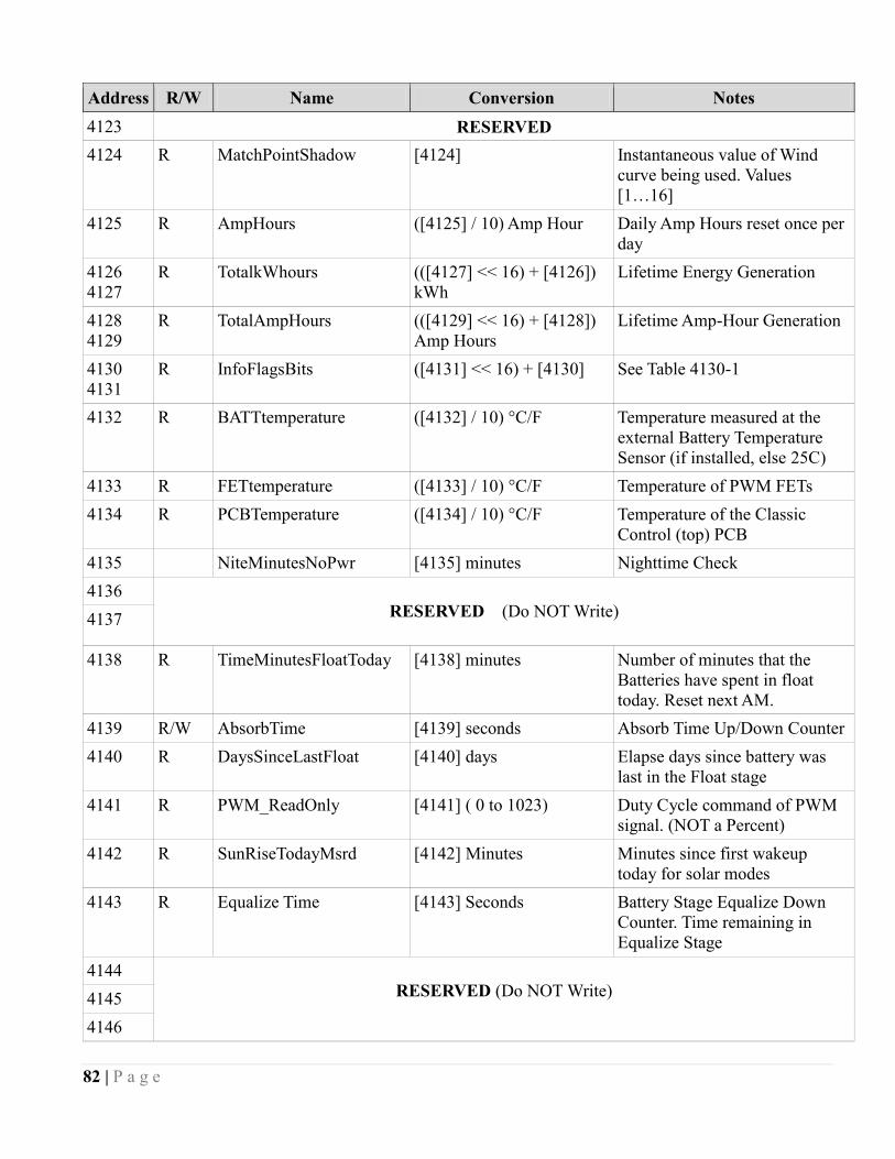
82 | P a g e
Address R/W Name Conversion Notes
4123 RESERVED
4124 R MatchPointShadow [4124] Instantaneous value of Wind
curve being used. Values
[1…16]
4125 R AmpHours ([4125] / 10) Amp Hour Daily Amp Hours reset once per
day
4126
4127
R TotalkWhours (([4127] << 16) + [4126])
kWh
Lifetime Energy Generation
4128
4129
R TotalAmpHours (([4129] << 16) + [4128])
Amp Hours
Lifetime Amp-Hour Generation
4130
4131
R InfoFlagsBits ([4131] << 16) + [4130] See Table 4130-1
4132 R BATTtemperature ([4132] / 10) °C/F Temperature measured at the
external Battery Temperature
Sensor (if installed, else 25C)
4133 R FETtemperature ([4133] / 10) °C/F Temperature of PWM FETs
4134 R PCBTemperature ([4134] / 10) °C/F Temperature of the Classic
Control (top) PCB
4135 NiteMinutesNoPwr [4135] minutes Nighttime Check
4136
RESERVED (Do NOT Write)
4137
4138 R TimeMinutesFloatToday [4138] minutes Number of minutes that the
Batteries have spent in float
today. Reset next AM.
4139 R/W AbsorbTime [4139] seconds Absorb Time Up/Down Counter
4140 R DaysSinceLastFloat [4140] days Elapse days since battery was
last in the Float stage
4141 R PWM_ReadOnly [4141] ( 0 to 1023) Duty Cycle command of PWM
signal. (NOT a Percent)
4142 R SunRiseTodayMsrd [4142] Minutes Minutes since first wakeup
today for solar modes
4143 R Equalize Time [4143] Seconds Battery Stage Equalize Down
Counter. Time remaining in
Equalize Stage
4144
RESERVED (Do NOT Write) 4145
4146
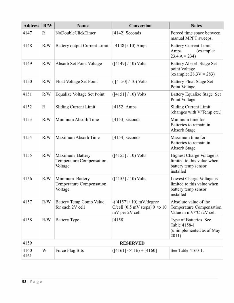
83 | P a g e
Address R/W Name Conversion Notes
4147 R NoDoubleClickTimer [4142] Seconds Forced time space between
manual MPPT sweeps.
4148 R/W Battery output Current Limit [4148] / 10) Amps Battery Current Limit
Amps (example:
23.4 A = 234)
4149 R/W Absorb Set Point Voltage ([4149] / 10) Volts Battery Absorb Stage Set
point Voltage
(example: 28.3V = 283)
4150 R/W Float Voltage Set Point ( [4150] / 10) Volts Battery Float Stage Set
Point Voltage
4151 R/W Equalize Voltage Set Point ([4151] / 10) Volts Battery Equalize Stage Set
Point Voltage
4152 R Sliding Current Limit [4152] Amps Sliding Current Limit
(changes with V/Temp etc.)
4153 R/W Minimum Absorb Time [4153] seconds Minimum time for
Batteries to remain in
Absorb Stage.
4154 R/W Maximum Absorb Time [4154] seconds Maximum time for
Batteries to remain in
Absorb Stage.
4155 R/W Maximum Battery
Temperature Compensation
Voltage
([4155] / 10) Volts Highest Charge Voltage is
limited to this value when
battery temp sensor
installed
4156 R/W Minimum Battery
Temperature Compensation
Voltage
([4155] / 10) Volts Lowest Charge Voltage is
limited to this value when
battery temp sensor
installed
4157 R/W Battery Temp Comp Value
for each 2V cell
-([4157] / 10) mV/degree
C/cell (0.5 mV steps) 0 to 10
mV per 2V cell
Absolute value of the
Temperature Compensation
Value in mV/°C /2V cell
4158 R/W Battery Type [4158] Type of Batteries. See
Table 4158-1
(unimplemented as of May
2011)
4159 RESERVED
4160
4161
W Force Flag Bits ([4161] << 16) + [4160] See Table 4160-1.
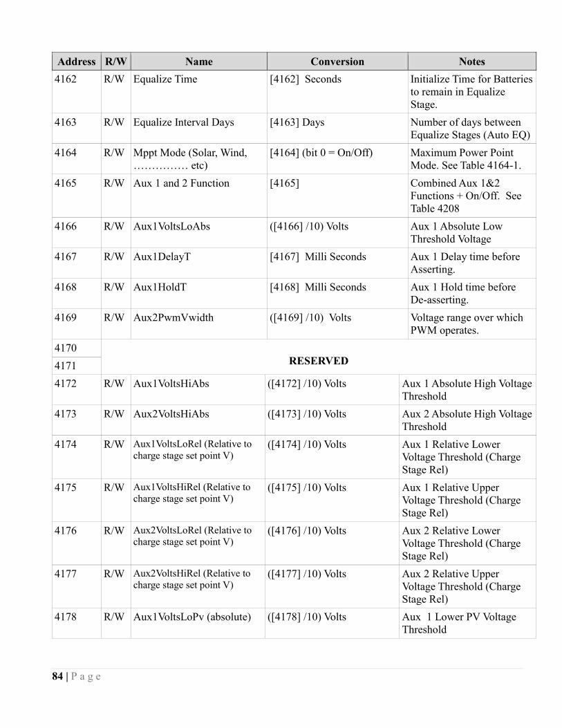
84 | P a g e
Address R/W Name Conversion Notes
4162 R/W Equalize Time [4162] Seconds Initialize Time for Batteries
to remain in Equalize
Stage.
4163 R/W Equalize Interval Days [4163] Days Number of days between
Equalize Stages (Auto EQ)
4164 R/W Mppt Mode (Solar, Wind,
…………… etc)
[4164] (bit 0 = On/Off) Maximum Power Point
Mode. See Table 4164-1.
4165 R/W Aux 1 and 2 Function [4165] Combined Aux 1&2
Functions + On/Off. See
Table 4208
4166 R/W Aux1VoltsLoAbs ([4166] /10) Volts Aux 1 Absolute Low
Threshold Voltage
4167 R/W Aux1DelayT [4167] Milli Seconds Aux 1 Delay time before
Asserting.
4168 R/W Aux1HoldT [4168] Milli Seconds Aux 1 Hold time before
De-asserting.
4169 R/W Aux2PwmVwidth ([4169] /10) Volts Voltage range over which
PWM operates.
4170
RESERVED 4171
4172 R/W Aux1VoltsHiAbs ([4172] /10) Volts Aux 1 Absolute High Voltage
Threshold
4173 R/W Aux2VoltsHiAbs ([4173] /10) Volts Aux 2 Absolute High Voltage
Threshold
4174 R/W Aux1VoltsLoRel (Relative to
charge stage set point V) ([4174] /10) Volts Aux 1 Relative Lower
Voltage Threshold (Charge
Stage Rel)
4175 R/W Aux1VoltsHiRel (Relative to
charge stage set point V) ([4175] /10) Volts Aux 1 Relative Upper
Voltage Threshold (Charge
Stage Rel)
4176 R/W Aux2VoltsLoRel (Relative to
charge stage set point V) ([4176] /10) Volts Aux 2 Relative Lower
Voltage Threshold (Charge
Stage Rel)
4177 R/W Aux2VoltsHiRel (Relative to
charge stage set point V) ([4177] /10) Volts Aux 2 Relative Upper
Voltage Threshold (Charge
Stage Rel)
4178 R/W Aux1VoltsLoPv (absolute) ([4178] /10) Volts Aux 1 Lower PV Voltage
Threshold
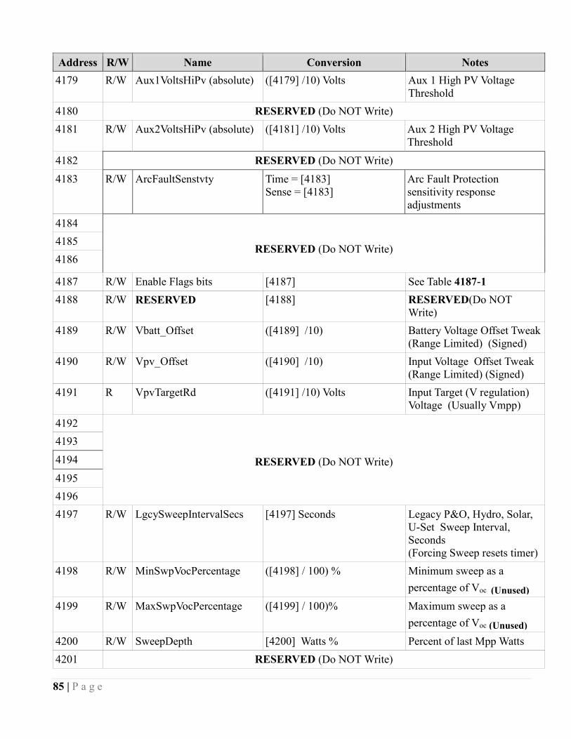
85 | P a g e
Address R/W Name Conversion Notes
4179 R/W Aux1VoltsHiPv (absolute) ([4179] /10) Volts Aux 1 High PV Voltage
Threshold
4180 RESERVED (Do NOT Write)
4181 R/W Aux2VoltsHiPv (absolute) ([4181] /10) Volts Aux 2 High PV Voltage
Threshold
4182 RESERVED (Do NOT Write)
4183 R/W ArcFaultSenstvty Time = [4183]
Sense = [4183]
Arc Fault Protection
sensitivity response
adjustments
4184
RESERVED (Do NOT Write) 4185
4186
4187 R/W Enable Flags bits [4187] See Table 4187-1
4188 R/W RESERVED [4188] RESERVED(Do NOT
Write)
4189 R/W Vbatt_Offset ([4189] /10) Battery Voltage Offset Tweak
(Range Limited) (Signed)
4190 R/W Vpv_Offset ([4190] /10) Input Voltage Offset Tweak
(Range Limited) (Signed)
4191 R VpvTargetRd ([4191] /10) Volts Input Target (V regulation)
Voltage (Usually Vmpp)
4192
RESERVED (Do NOT Write)
4193
4194
4195
4196
4197 R/W LgcySweepIntervalSecs [4197] Seconds Legacy P&O, Hydro, Solar,
U-Set Sweep Interval,
Seconds
(Forcing Sweep resets timer)
4198 R/W MinSwpVocPercentage ([4198] / 100) % Minimum sweep as a
percentage of Voc (Unused)
4199 R/W MaxSwpVocPercentage ([4199] / 100)% Maximum sweep as a
percentage of Voc (Unused)
4200 R/W SweepDepth [4200] Watts % Percent of last Mpp Watts
4201 RESERVED (Do NOT Write)
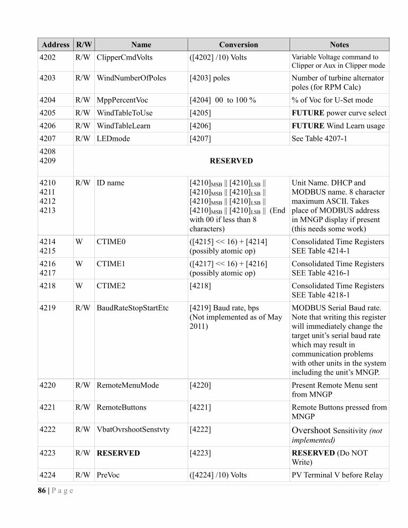
86 | P a g e
Address R/W Name Conversion Notes
4202 R/W ClipperCmdVolts ([4202] /10) Volts Variable Voltage command to
Clipper or Aux in Clipper mode
4203 R/W WindNumberOfPoles [4203] poles Number of turbine alternator
poles (for RPM Calc)
4204 R/W MppPercentVoc [4204] 00 to 100 % % of Voc for U-Set mode
4205 R/W WindTableToUse [4205] FUTURE power curve select
4206 R/W WindTableLearn [4206] FUTURE Wind Learn usage
4207 R/W LEDmode [4207] See Table 4207-1
4208
4209
RESERVED
4210
4211
4212
4213
R/W ID name [4210]MSB || [4210]LSB ||
[4210]MSB || [4210]LSB ||
[4210]MSB || [4210]LSB ||
[4210]MSB || [4210]LSB || (End
with 00 if less than 8
characters)
Unit Name. DHCP and
MODBUS name. 8 character
maximum ASCII. Takes
place of MODBUS address
in MNGP display if present
(this needs some work)
4214
4215
W CTIME0 ([4215] << 16) + [4214]
(possibly atomic op)
Consolidated Time Registers
SEE Table 4214-1
4216
4217
W CTIME1 ([4217] << 16) + [4216]
(possibly atomic op)
Consolidated Time Registers
SEE Table 4216-1
4218 W CTIME2 [4218] Consolidated Time Registers
SEE Table 4218-1
4219 R/W BaudRateStopStartEtc [4219] Baud rate, bps
(Not implemented as of May
2011)
MODBUS Serial Baud rate.
Note that writing this register
will immediately change the
target unit’s serial baud rate
which may result in
communication problems
with other units in the system
including the unit’s MNGP.
4220 R/W RemoteMenuMode [4220] Present Remote Menu sent
from MNGP
4221 R/W RemoteButtons [4221] Remote Buttons pressed from
MNGP
4222 R/W VbatOvrshootSenstvty [4222] Overshoot Sensitivity (not
implemented)
4223 R/W RESERVED [4223] RESERVED (Do NOT
Write)
4224 R/W PreVoc ([4224] /10) Volts PV Terminal V before Relay
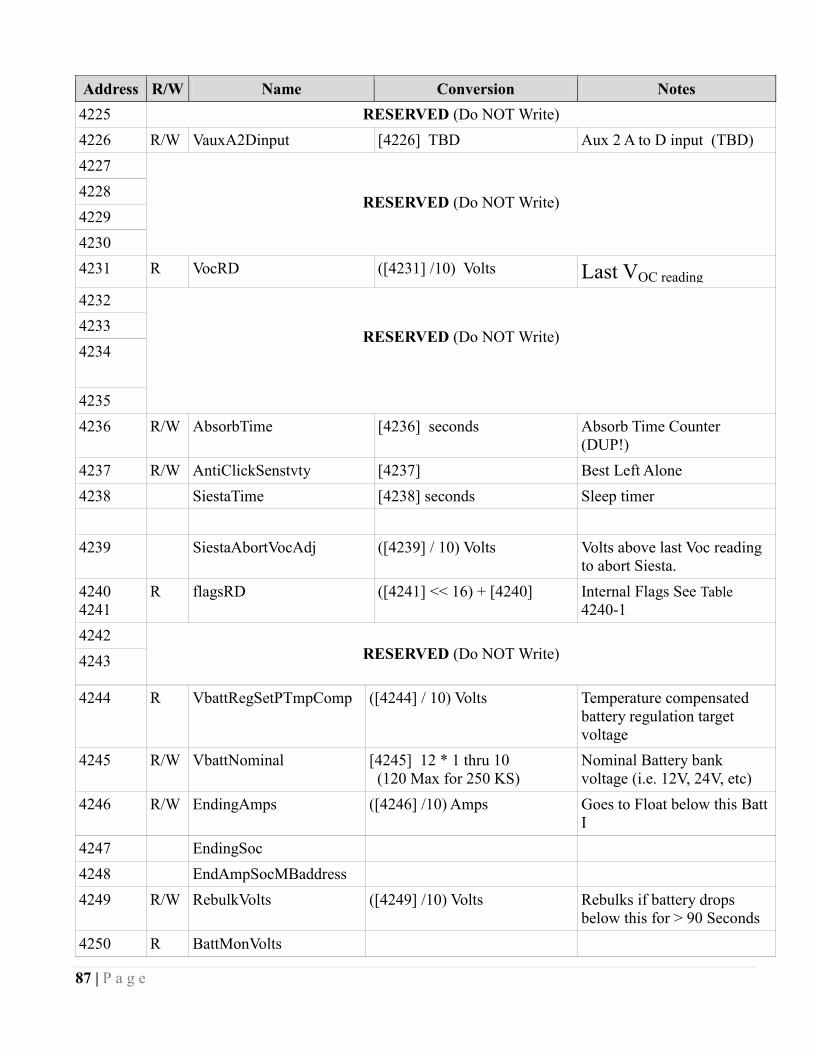
87 | P a g e
Address R/W Name Conversion Notes
4225 RESERVED (Do NOT Write)
4226 R/W VauxA2Dinput [4226] TBD Aux 2 A to D input (TBD)
4227
RESERVED (Do NOT Write) 4228
4229
4230
4231 R VocRD ([4231] /10) Volts Last VOC reading
4232
RESERVED (Do NOT Write)
4233
4234
4235
4236 R/W AbsorbTime [4236] seconds Absorb Time Counter
(DUP!)
4237 R/W AntiClickSenstvty [4237] Best Left Alone
4238 SiestaTime [4238] seconds Sleep timer
4239 SiestaAbortVocAdj ([4239] / 10) Volts Volts above last Voc reading
to abort Siesta.
4240
4241
R flagsRD ([4241] << 16) + [4240] Internal Flags See Table
4240-1
4242
RESERVED (Do NOT Write)
4243
4244 R VbattRegSetPTmpComp ([4244] / 10) Volts Temperature compensated
battery regulation target
voltage
4245 R/W VbattNominal [4245] 12 * 1 thru 10
(120 Max for 250 KS)
Nominal Battery bank
voltage (i.e. 12V, 24V, etc)
4246 R/W EndingAmps ([4246] /10) Amps Goes to Float below this Batt
I
4247 EndingSoc
4248 EndAmpSocMBaddress
4249 R/W RebulkVolts ([4249] /10) Volts Rebulks if battery drops
below this for > 90 Seconds
4250 R BattMonVolts
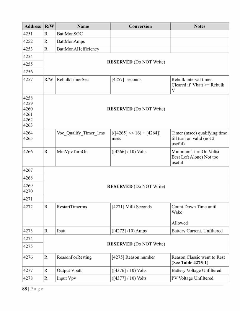
88 | P a g e
Address R/W Name Conversion Notes
4251 R BattMonSOC
4252 R BattMonAmps
4253 R BattMonAHefficiency
4254
RESERVED (Do NOT Write) 4255
4256
4257
R/W RebulkTimerSec [4257] seconds Rebulk interval timer.
Cleared if Vbatt >= Rebulk
V
4258
4259
4260
4261
4262
4263
RESERVED (Do NOT Write)
4264
4265
Voc_Qualify_Timer_1ms (([4265] << 16) + [4264])
msec
Timer (msec) qualifying time
till turn on valid (not 2
useful)
4266 R MinVpvTurnOn ([4266] / 10) Volts Minimum Turn On Volts(
Best Left Alone) Not too
useful
4267
RESERVED (Do NOT Write)
4268
4269
4270
4271
4272 R RestartTimerms [4271] Milli Seconds Count Down Time until
Wake
Allowed
4273 R Ibatt ([4272] /10) Amps Battery Current, Unfiltered
4274
RESERVED (Do NOT Write)
4275
4276 R ReasonForResting [4275] Reason number Reason Classic went to Rest
(See Table 4275-1)
4277 R Output Vbatt ([4376] / 10) Volts Battery Voltage Unfiltered
4278 R Input Vpv ([4377] / 10) Volts PV Voltage Unfiltered
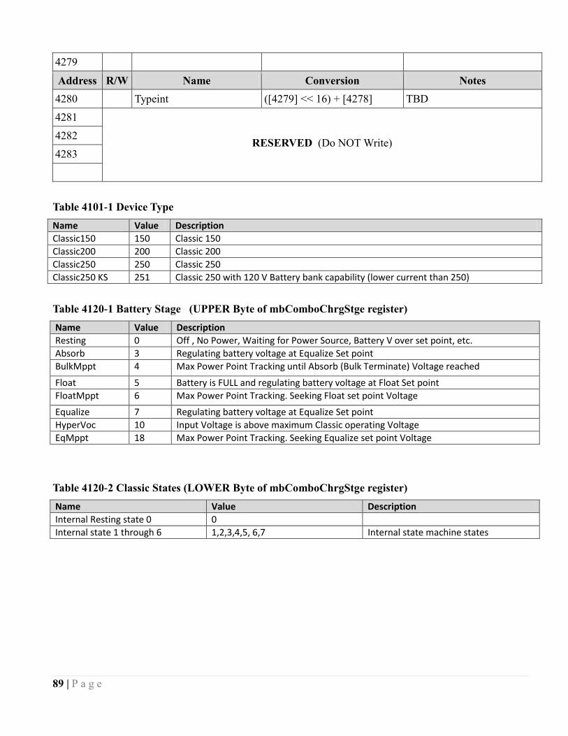
89 | P a g e
4279
Address R/W Name Conversion Notes
4280 Typeint ([4279] << 16) + [4278] TBD
4281
RESERVED (Do NOT Write) 4282
4283
Table 4101-1 Device Type
Name Value Description
Classic150 150 Classic 150
Classic200 200 Classic 200
Classic250 250 Classic 250
Classic250 KS 251 Classic 250 with 120 V Battery bank capability (lower current than 250)
Table 4120-1 Battery Stage (UPPER Byte of mbComboChrgStge register)
Name Value Description
Resting 0 Off , No Power, Waiting for Power Source, Battery V over set point, etc.
Absorb 3 Regulating battery voltage at Equalize Set point
BulkMppt 4 Max Power Point Tracking until Absorb (Bulk Terminate) Voltage reached
Float 5 Battery is FULL and regulating battery voltage at Float Set point
FloatMppt 6 Max Power Point Tracking. Seeking Float set point Voltage
Equalize 7 Regulating battery voltage at Equalize Set point
HyperVoc 10 Input Voltage is above maximum Classic operating Voltage
EqMppt 18 Max Power Point Tracking. Seeking Equalize set point Voltage
Table 4120-2 Classic States (LOWER Byte of mbComboChrgStge register)
Name Value Description
Internal Resting state 0 0
Internal state 1 through 6 1,2,3,4,5, 6,7 Internal state machine states
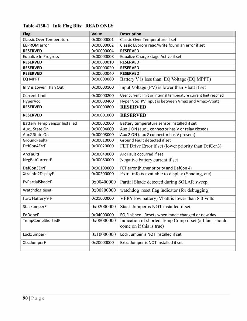
90 | P a g e
Table 4130-1 Info Flag Bits: READ ONLY
Flag Value Description
Classic Over Temperature 0x00000001 Classic Over Temperature if set
EEPROM error 0x00000002 Classic EEprom read/write found an error if set
RESERVED 0x00000004 RESERVED
Equalize In Progress 0x00000008 Equalize Charge stage Active if set
RESERVED 0x00000010 RESERVED
RESERVED 0x00000020 RESERVED
RESERVED 0x00000040 RESERVED
EQ MPPT 0x00000080 Battery V is less than EQ Voltage (EQ MPPT)
In V is Lower Than Out 0x00000100 Input Voltage (PV) is lower than Vbatt if set
Current Limit 0x00000200 User current limit or internal temperature current limt reached
HyperVoc 0x00000400 Hyper Voc PV input is between Vmax and Vmax+Vbatt
RESERVED 0x00000800 RESERVED
RESERVED 0x00001000 RESERVED
Battery Temp Sensor Installed 0x00002000 Battery temperature sensor installed if set
Aux1 State On 0x00004000 Aux 1 ON (aux 1 connector has V or relay closed)
Aux2 State On 0x00008000 Aux 2 ON (aux 2 connector has V present)
GroundFaultF 0x00010000 Ground Fault detected if set
DefCon4ErrF 0x00020000 FET Drive Error if set (lower priority than DefCon3)
ArcFaultF 0x00040000 Arc Fault occurred if set
NegBatCurrentF 0x00080000 Negative battery current if set
DefCon3ErrF 0x00100000 FET error (higher priority and DefCon 4)
XtraInfo2DsplayF 0x00200000 Extra info is available to display (Shading, etc)
PvPartialShadeF 0x00400000 Partial Shade detected during SOLAR sweep
WatchdogResetF 0x00800000 watchdog reset flag indicator (for debugging)
LowBatteryVF 0x01000000 VERY low battery) Vbatt is lower than 8.0 Volts
StackumperF 0x02000000 Stack Jumper is NOT installed if set
EqDoneF 0x04000000 EQ Finished. Resets when mode changed or new day
TempCompShortedF 0x08000000 Indication of shorted Temp Comp if set (all fans should
come on if this is true)
LockJumperF 0x10000000 Lock Jumper is NOT installed if set
XtraJumperF 0x20000000 Extra Jumper is NOT installed if set

91 | P a g e
Table 4158-1 Battery Type (not used yet as of May 2011)
Name Value Description
Flooded 1 Lead Acid (Flooded)
Gel 2 Lead Acid (Gel)
AGM 3 Lead Acid (AGM)
AGM2 4 Lead Acid (AGM2)
Lithium 5 LiIon
Nicad 6 Nickel Cadmium
VRLA 7 AGM or AGM or AGM2 actually
AbsolyteIIP 8 TBD
User1 9 TBD
Table 4160-1 ForceFlagsBits (can write to low or high 16 bits independently if wanted)
Name Value Description
RESERVED 0x00000001 RESERVED (Do NOT Set to 1)
ForceRstDailyKwHrsF 0x00000002 Reset Daily kWh count
ForceEEpromUpdateWriteF 0x00000004 Write all current settings to internal EEPROM
ForceEEpromInitReadF 0x00000008
Reset all values to EEPROM defaults (MAY not work yet)
ForceResetInfoFlags 0x00000010 Force ALL Info Flags to zero when set to 1 (Will reset info flags to 0) (or course some may pop back to 1 after reset-ting if applicable)
ForceFloatF 0x00000020 Force battery charge stage to Float
ForceBulkF 0x00000040 Force new Bulk/Absorb charge stage
ForceEqualizeF 0x00000080 Force new Equalize stage
ForceNiteF 0x00000100 Force a new night time
Force25HrDayF 0x00000200 Otherwise it's a 24 Hour day
ForcePandOsweepF 0x00000400 Force a Mini-Sweep for Legacy P&O mode
ForceSweepF 0x00000800 Force a Sweep (at least for U-Set)
RESERVED 0x00001000 RESERVED(Do NOT Set to 1)
ForceGetTimeF 0x00002000 Set time from MNGP Remote Modbus (CTIME)
RESERVED 0x00004000 RESERVED(Do NOT Set to 1)
RESERVED 0x00008000 RESERVED(Do NOT Set to 1)
RESERVED 0x00010000 RESERVED(Do NOT Set to 1)
RESERVED 0x00020000 RESERVED(Do NOT Set to 1)
RESERVED 0x00040000 RESERVED(Do NOT Set to 1)
RESERVED 0x00080000 RESERVED(Do NOT Set to 1)
RESERVED 0x00100000 RESERVED(Do NOT Set to 1)
RESERVED 0x00200000 RESERVED(Do NOT Set to 1)
RESERVED 0x00400000 RESERVED(Do NOT Set to 1)
ForceResetFaultsF 0x00800000 Just reset all of the faults
RESERVED 0x01000000 RESERVED(Do NOT Set to 1)

92 | P a g e
Table 4164-1 MPPT MODE†
` Value Description
PV_Uset 0x0001 U-SET MPPT MODE (includes MPPT ENABLED (On) FLAG i.e. if 0x0000 MPPT mode is OFF)
DYNAMIC 0x0003 Slow Dynamic Solar Tracking (old Solar 1 O & P )
Legacy P&O 0x0009 Legacy P & O sweep mode
SOLAR 0x000B Fast SOLAR track (old PV Learn mode)
MICRO HYDRO 0x000D Micro Hydro mode (similar to Legacy P&O)
WIND TRACK 0x0005 Wind Track Mode
WIND LEARN (future mode) 0x0007 Wind Learn Mode (not implemented as of May 2011)
PV COMBO 1 0x000F PV COMBO 1
RESERVED 0x0011 RESERVED
BOOST CHRG 0x0013 Boost Charge Mode (Lower to Higher Voltage, Unimplement-ed as of May 2011)
†Bit 0 is the ON/OFF (Enable/Disable) Table shows modes as ON
NOTE: MPPT MODE will automatically revert to OFF during mode change
Table 4207-1 LED Mode
Name Value Description
All Off 0 No LED activity except on startup
Rick Mode 1 Minimal Activity: Remote Yellow LED indicates Current
Limiting or FET Temperature Limit.
Blinky 2 All LEDs Active: Lightshow!
MNGP Red LED : MNGP->Classic MODBUS active
LED 1 3 Status Mode:
MNGP Green LED = Battery Full (Float)
Classic Red LED = Aux 1 Active.
Classic Yellow LED = Aux 2 Active
Classic Blue LED = Unimplemented
LED 2 4 Unimplemented
LED 3 5 Unimplemented
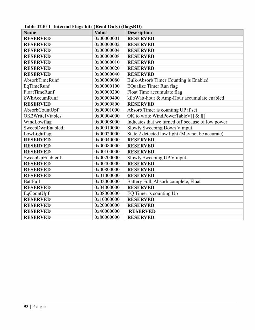
93 | P a g e
Table 4240-1 Internal Flags bits (Read Only) (flagsRD)
Name Value Description
RESERVED 0x00000001 RESERVED
RESERVED 0x00000002 RESERVED
RESERVED 0x00000004 RESERVED
RESERVED 0x00000008 RESERVED
RESERVED 0x00000010 RESERVED
RESERVED 0x00000020 RESERVED
RESERVED 0x00000040 RESERVED
AbsorbTimeRunf 0x00000080 Bulk/Absorb Timer Counting is Enabled
EqTimeRunf 0x00000100 EQualize Timer Run flag
FloatTimeRunf 0x00000200 Float Time accumulate flag
kWhAccumRunf 0x00000400 kiloWatt-hour & Amp-Hour accumulate enabled
RESERVED 0x00000800 RESERVED
AbsorbCountUpf 0x00001000 Absorb Timer is counting UP if set
OK2WriteIVtables 0x00004000 OK to write WindPowerTableV[] & I[]
WindLowflag 0x00008000 Indicates that we turned off because of low power
SweepDwnEnabledf 0x00010000 Slowly Sweeping Down V input
LowLightflag 0x00020000 State 2 detected low light (May not be accurate)
RESERVED 0x00040000 RESERVED
RESERVED 0x00080000 RESERVED
RESERVED 0x00100000 RESERVED
SweepUpEnabledf 0x00200000 Slowly Sweeping UP V input
RESERVED 0x00400000 RESERVED
RESERVED 0x00800000 RESERVED
RESERVED 0x01000000 RESERVED
BattFull 0x02000000 Battery Full, Absorb complete, Float
RESERVED 0x04000000 RESERVED
EqCountUpf 0x08000000 EQ Timer is counting Up
RESERVED 0x10000000 RESERVED
RESERVED 0x20000000 RESERVED
RESERVED 0x40000000 RESERVED
RESERVED 0x80000000 RESERVED

94 | P a g e
AUX 1 and 2 modes
Extracted and encoded as combined in Aux12Function
Table 4165-1 AUX 1 Off – Auto – On (Extracted/Encoded as Aux12Function bits 6,7)
Name Value Description
Aux 1 Off 0 Aux 1 output is OFF (0 Volts)
Aux 1 Auto 1 Aux 1 operates as defined in Aux2Funtion
Aux 1 On 2 Aux 1 output is ON (~14 Volts)
Aux 1 Unimplemented 3 Unassigned at present
Aux1OffAutoOn = (((Aux12Function & 0xc0) >> 6));
Table 4165-2 AUX 2 Off – Auto – On (Extracted/Encoded as Aux12Function bits 14,15)
Name Value Description
Aux 2 Off 0 Aux 2 output is OFF (0 Volts)
Aux 2 Auto 1 Aux 2 operates as defined in Aux2Funtion
Aux 2 On 2 Aux 2 output is ON (~14 Volts)
Aux 2 Unimplemented 3 Unassigned at present
Aux2OffAutoOn = ((Aux12FunctionS & 0xc000) >> 14);
Table 4165-3 AUX 1 Function (Extracted/Encoded as Aux12Function bits 0-5)
Name Value Description
DIVERSION SLW+ 1 Non-PWM On at Vbatt > Aux1VoltsHiAbs
Off at Vbatt < Aux1VoltsLoAbs (Active High)
DIVERSION SLW- 2 Same as DIVERSION SLW+ but Active Low
BAT DIV V REL+ 3 Non-PWM On at Vbatt > Aux1VoltsHiAbs
Off at Vbatt < Aux1VoltsLoAbs (Active High)
BAT DIV V REL- 4 Non-PWM On at Vbatt > Aux1VoltsHiAbs
Off at Vbatt < Aux1VoltsLoAbs (Active Low)
PV V TRIGGER + 7 Active High output if Vin exceeds Aux1VoltsHiPv
PV V TRIGGER - 8 Active Low output if Vin exceeds Aux1VoltsHiPv
MANUAL ON-OFF 9 MANUAL On/Off allowed using Off-Auto-On Selection
TOGGLE TEST 13 Out Once per second On-Off-On-Off automatic toggle
NITE LITE HIGH 14 Active High indicating Night Time. Inactive at Wakeup
NITE LITE LOW 15 Active Low indicating Night Time. Inactive at Wakeup
WIND CLIPPER 16 Output goes Active High when V input is above PV input V
plus headroom voltage
Aux1Function = Aux12Function & 0x3f;
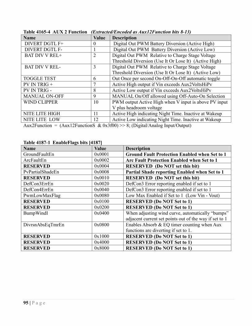
95 | P a g e
Table 4165-4 AUX 2 Function (Extracted/Encoded as Aux12Function bits 8-13)
Name Value Description
DIVERT DGTL F+ 0 Digital Out PWM Battery Diversion (Active High)
DIVERT DGTL F- 1 Digital Out PWM Battery Diversion (Active Low)
BAT DIV V REL+ 2 Digital Out PWM Relative to Charge Stage Voltage
Threshold Diversion (Use It Or Lose It) (Active High)
BAT DIV V REL- 3 Digital Out PWM Relative to Charge Stage Voltage
Threshold Diversion (Use It Or Lose It) (Active Low)
TOGGLE TEST 6 Out Once per second On-Off-On-Off automatic toggle
PV IN TRIG + 7 Active High output if Vin exceeds Aux2VoltsHiPv
PV IN TRIG - 8 Active Low output if Vin exceeds Aux2VoltsHiPv
MANUAL ON-OFF 9 MANUAL On/Off allowed using Off-Auto-On Selection
WIND CLIPPER 10 PWM output Active High when V input is above PV input
V plus headroom voltage
NITE LITE HIGH 11 Active High indicating Night Time. Inactive at Wakeup
NITE LITE LOW 12 Active Low indicating Night Time. Inactive at Wakeup
Aux2Function = (Aux12FunctionS & 0x3f00) >> 8; (Digital/Analog Input/Output)
Table 4187-1 EnableFlags bits [4187]
Name Value Description
GroundFaultEn 0x0001 Ground Fault Protection Enabled when Set to 1
ArcFaultEn 0x0002 Arc Fault Protection Enabled when Set to 1
RESERVED 0x0004 RESERVED (Do NOT set this bit)
PvPartialShadeEn 0x0008 Partial Shade reporting Enabled when Set to 1
RESERVED 0x0010 RESERVED (Do NOT set this bit)
DefCon3ErrEn 0x0020 DefCon3 Error reporting enabled if set to 1
DefCon4ErrEn 0x0040 DefCon3 Error reporting enabled if set to 1
PwmLowMaxFlag 0x0080 Low Max Enabled if Set to 1 (Low Vin - Vout)
RESERVED 0x0100 RESERVED (Do NOT Set to 1)
RESERVED 0x0200 RESERVED (Do NOT Set to 1)
BumpWindI 0x0400 When adjusting wind curve, automatically “bumps”
adjacent current set points out of the way if set to 1
DivrsnAbsEqTmrEn 0x0800 Enables Absorb & EQ timer counting when Aux
functions are diverting if set to 1.
RESERVED 0x1000 RESERVED (Do NOT Set to 1)
RESERVED 0x4000 RESERVED (Do NOT Set to 1)
RESERVED 0x8000 RESERVED (Do NOT Set to 1)
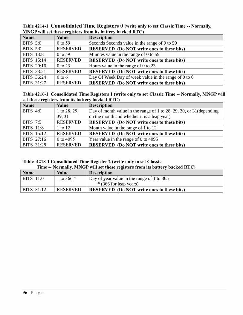
96 | P a g e
Table 4214-1 Consolidated Time Registers 0 (write only to set Classic Time -- Normally,
MNGP will set these registers from its battery backed RTC)
Name Value Description
BITS 5:0 0 to 59 Seconds Seconds value in the range of 0 to 59
BITS 5:0 RESERVED RESERVED (Do NOT write ones to these bits)
BITS 13:8 0 to 59 Minutes value in the range of 0 to 59
BITS 15:14 RESERVED RESERVED (Do NOT write ones to these bits)
BITS 20:16 0 to 23 Hours value in the range of 0 to 23
BITS 23:21 RESERVED RESERVED (Do NOT write ones to these bits)
BITS 36:24 0 to 6 Day Of Week Day of week value in the range of 0 to 6
BITS 31:27 RESERVED RESERVED (Do NOT write ones to these bits)
Table 4216-1 Consolidated Time Registers 1 (write only to set Classic Time -- Normally, MNGP will
set these registers from its battery backed RTC)
Name Value Description
BITS 4:0 1 to 28, 29,
39, 31
Day of month value in the range of 1 to 28, 29, 30, or 31(depending
on the month and whether it is a leap year)
BITS 7:5 RESERVED RESERVED (Do NOT write ones to these bits)
BITS 11:8 1 to 12 Month value in the range of 1 to 12
BITS 15:12 RESERVED RESERVED (Do NOT write ones to these bits)
BITS 27:16 0 to 4095 Year value in the range of 0 to 4095
BITS 31:28 RESERVED RESERVED (Do NOT write ones to these bits)
Table 4218-1 Consolidated Time Register 2 (write only to set Classic
Time -- Normally, MNGP will set these registers from its battery backed RTC)
Name Value Description
BITS 11:0 1 to 366 * Day of year value in the range of 1 to 365
* (366 for leap years)
BITS 31:12 RESERVED RESERVED (Do NOT write ones to these bits)

97 | P a g e
Table 4275-1 Reason For Resting
VALUE REASON FOR RESTING
1 Anti-Click. Not enough power available (Wake Up)
2 Insane Ibatt Measurement (Wake Up)
3 Negative Current (load on PV input ?) (Wake Up)
4 PV Input Voltage lower than Battery V (Vreg state)
5 Too low of power out and Vbatt below set point for > 90 seconds
6 FET temperature too high (always shows up on boot up) (Cover is on maybe ?)
7 Ground Fault Detected
8 Arc Fault Detected
9 Too much negative current while operating
10 Battery is less than 8.0 Volts
11 PV input is available but V is rising too slowly. Low Light or bad connection
12 Voc has gone down from last Voc or low light. Re-check
13 Voc has gone up from last Voc enough to be suspicious. Re-check
14 Same as 11
15 Same as 12
16 Mppt MODE is OFF (Usually because user turned it off)
17 PV input is higher than operation range (too high for 150V Classic)
18 PV input is higher than operation range (too high for 200V Classic)
19 PV input is higher than operation range (too high for 250V or 250KS)
25 Battery Voltage too high of Overshoot (small battery or bad cable ?)

98 | P a g e
The network registers are all Read/Write. You may write any values to these registers, however this may
result in erratic operation in some instances.
To set A static IP address, be sure to clear the DHCP bit in register 20481 before writing the static values
to the
Network
Address Name Units Description
20481 IP Settings [20481] Network Settings Flags. See
Table 20481-1
20482
20483
IP Address [20483]MSB . [20483]LSB .
[20482]MSB . [20482]LSB
The IP address of the
Classic†
20484
20485
Gateway Address [20485]MSB . [20485]LSB .
[20484]MSB . [20484]LSB
Network Gateway Address. †
20486
20487
Subnet [20487]MSB . [20487]LSB .
[20486]MSB . [20486]LSB
Network Subnet Mask†
20488
20489
DNS_1 [20489]MSB . [20489]LSB .
[20488]MSB . [20488]LSB
Primary DNS Address†
20490
20491
DNS_2 [20491]MSB . [20491]LSB .
[20490]MSB . [20490]LSB
Secondary/Alternate DNS
Address†
† Read Only if the DHCP flag is set. To assign a static IP to the Classic, first clear the DHCP flag in the IP
Settings Register (20481).
Table 20481-1
Name Value Description
DHCP 0x0001 Set this bit to enable DHCP.
Web Access 0x0002 Set this bit to enable online access to your Classic
through http://www.mymidnite.com

99 | P a g e
The Version Registers are all Read Only. Writes to any of these registers will have no long-term effect.
Version
Address Name units Description
16385 app_version Major: [16385](15…12)
Minor: [16385](11…8)
Release: [16385](8..4)
Release version of the application code
16386 net_version, Major: [16386](15…12)
Minor: [16386](11…8)
Release: [16386](8…4)
Release version of the communications stack
16387
16388
app_rev ([16388] << 16) +
[16387]
Build Revision of the application code
16389
16390
net_rev ([16390] << 16) +
[16389]
Build Revision of the communications code
stack

100 | P a g e
Communication Statistics are all Read/Write registers. You may write any value to these registers which
will be incremented should the trigger for that counter occur. The most useful type of write may be to
periodically reset the counters to zero. These are all lifetime counters and due to the number of MODBUS
transactions may overflow to 0.
Communication Statistics
Address Name units Description
Master / In Bus Interface
10001
10002
rx_ok
([10002] << 16) +
[10001]
Number of correctly received packets
10003
10004
rx_crc_err ([10004] << 16) +
[10003]
Number of packets received with crc errors
10005
10006
requested_ok ([10006] << 16) +
[10005]
Number of transactions originating from
this unit that completed successfully
10007
10008
requested_err ([10008] << 16) +
[10007]
Number of transactions originating from
this unit that failed
10009
10010
forwarded ([10010] << 16) +
[10009]
Number of packets forwarded through this
interface
10011
10012
broadcast ([10012] << 16) +
[10011]
Number of broadcast packets received
10013
10014
dropped_busy ([10014] << 16) +
(10013)
Number of packets dropped due to the
interface being busy.
10015
10016 RESERVED
Slave / Out bus interface
10017
10018
rx_ok
([10018] << 16) +
[10007]
Number of correctly received packets
10019
10020
rx_crc_err ([10020] << 16) +
[10020]
Number of packets received with crc errors
10021
10022
requested_ok ([10022] << 16) +
[10021]
Number of transactions originating from
this unit that completed successfully
10023
10024
requested_err ([10024] << 16) +
[10023]
Number of transactions originating from
this unit that failed
10025
10026
forwarded ([10026] << 16) +
[10025]
Number of packets forwarded through this
interface
10027
10028
broadcast ([10028] << 16) +
[10027]
Number of broadcast packets received
10029
10030
dropped_busy ([10030] << 16) +
[10029]
Number of packets dropped due to the
interface being busy.
10031
10032 RESERVED

101 | P a g e
Communication Statistics
Remote bus interface
10033
10034
rx_ok
([10034] << 16) +
[10033]
Number of correctly received packets
10035
10036
rx_crc_err ([10036] << 16) +
[10035]
Number of packets received with crc errors
10037
10038
requested_ok ([10038] << 16) +
[10037]
Number of transactions originating from
this unit that completed successfully
10039
10040
requested_err ([10040] << 16) +
[10039]
Number of transactions originating from
this unit that failed
10041
10042
forwarded ([10042] << 16) +
[10041]
Number of packets forwarded through this
interface
10043
10044
broadcast ([10044] << 16) +
[10043]
Number of broadcast packets received
10045
10046
dropped_busy ([10046] << 16) +
[10045]
Number of packets dropped due to the
interface being busy.
10047
10048 RESERVED
TCP bus interface
10049
10050
rx_ok
([10050] << 16) +
[10049]
Number of correctly received packets
10051
10052
rx_crc_err ([10052] << 16) +
[10051]
Number of packets received with crc errors
10053
10054
requested_ok ([10054] << 16) +
[10053]
Number of transactions originating from
this unit that completed successfully
10055
10056
requested_err ([10056] << 16) +
[10055]
Number of transactions originating from
this unit that failed
10057
10058
forwarded ([10058] << 16) +
[10057]
Number of packets forwarded through this
interface
10059
10060
broadcast ([10060] << 16) +
[10059]
Number of broadcast packets received
10061
10062
dropped_busy ([10062] << 16) +
[10061]
Number of packets dropped due to the
interface being busy.
10063
10064 RESERVED
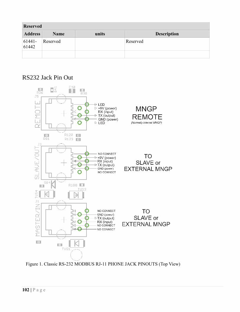
102 | P a g e
Reserved
Address Name units Description
61441-
61442
Reserved Reserved
RS232 Jack Pin Out
Figure 1. Classic RS-232 MODBUS RJ-11 PHONE JACK PINOUTS (Top View)