Embed Size (px)
Citation preview

Version 1.0 Published December 2017
Copyright©2017 ASRock INC. All rights reserved.
Copyright Notice:No part of this documentation may be reproduced, transcribed, transmitted, or translated in any language, in any form or by any means, except duplication of documentation by the purchaser for backup purpose, without written consent of ASRock Inc.
Products and corporate names appearing in this documentation may or may not be registered trademarks or copyrights of their respective companies, and are used only for identification or explanation and to the owners’ benefit, without intent to infringe.
Disclaimer:Specifications and information contained in this documentation are furnished for informational use only and subject to change without notice, and should not be constructed as a commitment by ASRock. ASRock assumes no responsibility for any errors or omissions that may appear in this documentation.
With respect to the contents of this documentation, ASRock does not provide warranty of any kind, either expressed or implied, including but not limited to the implied warranties or conditions of merchantability or fitness for a particular purpose.
In no event shall ASRock, its directors, officers, employees, or agents be liable for any indirect, special, incidental, or consequential damages (including damages for loss of profits, loss of business, loss of data, interruption of business and the like), even if ASRock has been advised of the possibility of such damages arising from any defect or error in the documentation or product.
This device complies with Part 15 of the FCC Rules. Operation is subject to the following two conditions: (1) this device may not cause harmful interference, and (2) this device must accept any interference received, including interference that
may cause undesired operation.
CALIFORNIA, USA ONLYThe Lithium battery adopted on this motherboard contains Perchlorate, a toxic substance controlled in Perchlorate Best Management Practices (BMP) regulations passed by the California Legislature. When you discard the Lithium battery in California, USA, please follow the related regulations in advance.“Perchlorate Material-special handling may apply, see www.dtsc.ca.gov/hazardouswaste/perchlorate”
ASRock Website: http://www.asrock.com

AUSTRALIA ONLYOur goods come with guarantees that cannot be excluded under the Australian Consumer Law. You are entitled to a replacement or refund for a major failure and compensation for any other reasonably foreseeable loss or damage caused by our goods. You are also entitled to have the goods repaired or replaced if the goods fail to be of acceptable quality and the failure does not amount to a major failure. If you require assistance please call ASRock Tel : +886-2-28965588 ext.123 (Standard International call charges apply) The terms HDMI™ and HDMI High-Definition Multimedia Interface, and the HDMI logo are trademarks or registered trademarks of HDMI Licensing LLC in the United States and other countries.
Contents
Chapter 1 Introduction 1
1.1 Package Contents 1
1.2 Specifications 2
1.3 Motherboard Layout 5
1.4 I/O Panel 7
Chapter 2 Installation 9
2.1 Installation of Memory Modules (SO-DIMM) 10
2.2 Expansion Slot (PCI Express Slot) 12
2.3 Jumpers Setup 13
2.4 Onboard Headers and Connectors 14
2.5 M.2 WiFi/BT Module Installation Guide 17
Chapter 3 Software and Utilities Operation 19
3.1 Installing Drivers 19
3.2 ASRock Live Update & APP Shop 20
3.2.1 UI Overview 20
3.2.2 Apps 21
3.2.3 BIOS & Drivers 24
3.2.4 Setting 25
Chapter 4 UEFI SETUP UTILITY 26
4.1 Introduction 26
4.1.1 UEFI Menu Bar 26
4.1.2 Navigation Keys 27
4.2 Main Screen 28
4.3 Advanced Screen 29
4.3.1 CPU Configuration 30
4.3.2 Chipset Configuration 31
4.3.3 Storage Configuration 33
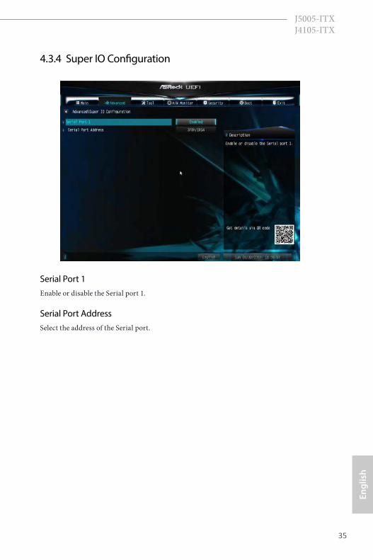
4.3.4 Super IO Configuration 35
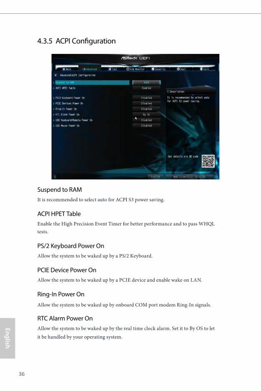
4.3.5 ACPI Configuration 36
4.3.6 USB Configuration 38
4.4 Tools 39
4.5 Hardware Health Event Monitoring Screen 41
4.6 Security Screen 42
4.7 Boot Screen 43
4.8 Exit Screen 45
1
Engl
ish
J5005-ITX J4105-ITX
Chapter 1 IntroductionThank you for purchasing ASRock J5005-ITX/J4105-ITX motherboard, a reliable motherboard produced under ASRock’s consistently stringent quality control. It delivers excellent performance with robust design conforming to ASRock’s commitment to quality and endurance.
In this manual, Chapter 1 and 2 contains the introduction of the motherboard and step-by-step installation guides. Chapter 3 contains the operation guide of the software and utilities. Chapter 4 contains the configuration guide of the BIOS setup.
1.1 Package Contents• ASRock J5005-ITX/J4105-ITX Motherboard (Mini-ITX Form Factor)• ASRock J5005-ITX/J4105-ITX Quick Installation Guide • ASRock J5005-ITX/J4105-ITX Support CD • 2 x Serial ATA (SATA) Data Cables (Optional)• 1 x I/O Panel Shield• 1 x Screw for M.2 Socket (Optional)
Because the motherboard specifications and the BIOS software might be updated, the content of this documentation will be subject to change without notice. In case any modifications of this documentation occur, the updated version will be available on ASRock’s website without further notice. If you require technical support related to this motherboard, please visit our website for specific information about the model you are using. You may find the latest VGA cards and CPU support list on ASRock’s website as well. ASRock website http://www.asrock.com.
2
English
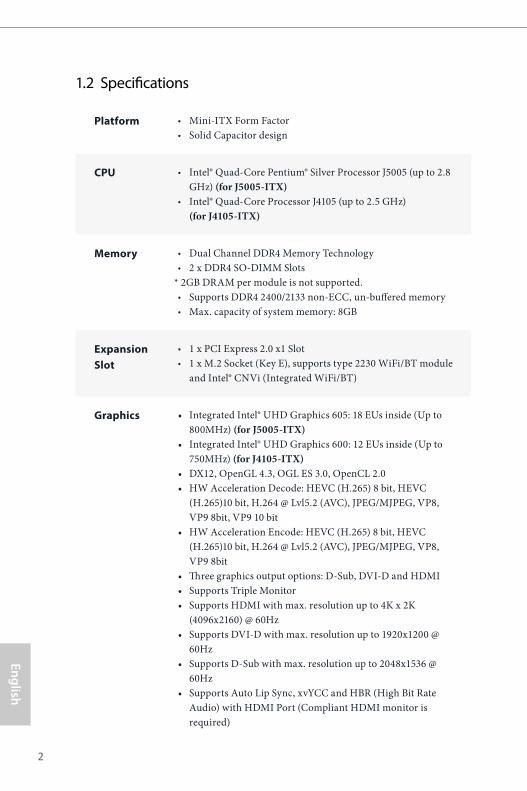
1.2 Specifications
Platform • Mini-ITX Form Factor• Solid Capacitor design
CPU • Intel® Quad-Core Pentium® Silver Processor J5005 (up to 2.8 GHz) (for J5005-ITX)
• Intel® Quad-Core Processor J4105 (up to 2.5 GHz) (for J4105-ITX)
Memory • Dual Channel DDR4 Memory Technology• 2 x DDR4 SO-DIMM Slots
* 2GB DRAM per module is not supported.• Supports DDR4 2400/2133 non-ECC, un-buffered memory • Max. capacity of system memory: 8GB
Expansion Slot
• 1 x PCI Express 2.0 x1 Slot• 1 x M.2 Socket (Key E), supports type 2230 WiFi/BT module
and Intel® CNVi (Integrated WiFi/BT)
Graphics • Integrated Intel® UHD Graphics 605: 18 EUs inside (Up to 800MHz) (for J5005-ITX)
• Integrated Intel® UHD Graphics 600: 12 EUs inside (Up to 750MHz) (for J4105-ITX)
• DX12, OpenGL 4.3, OGL ES 3.0, OpenCL 2.0• HW Acceleration Decode: HEVC (H.265) 8 bit, HEVC
(H.265)10 bit, H.264 @ Lvl5.2 (AVC), JPEG/MJPEG, VP8, VP9 8bit, VP9 10 bit
• HW Acceleration Encode: HEVC (H.265) 8 bit, HEVC (H.265)10 bit, H.264 @ Lvl5.2 (AVC), JPEG/MJPEG, VP8, VP9 8bit
• Three graphics output options: D-Sub, DVI-D and HDMI • Supports Triple Monitor• Supports HDMI with max. resolution up to 4K x 2K
(4096x2160) @ 60Hz• Supports DVI-D with max. resolution up to 1920x1200 @
60Hz• Supports D-Sub with max. resolution up to 2048x1536 @
60Hz• Supports Auto Lip Sync, xvYCC and HBR (High Bit Rate
Audio) with HDMI Port (Compliant HDMI monitor is required)
3
Engl
ish
J5005-ITX J4105-ITX
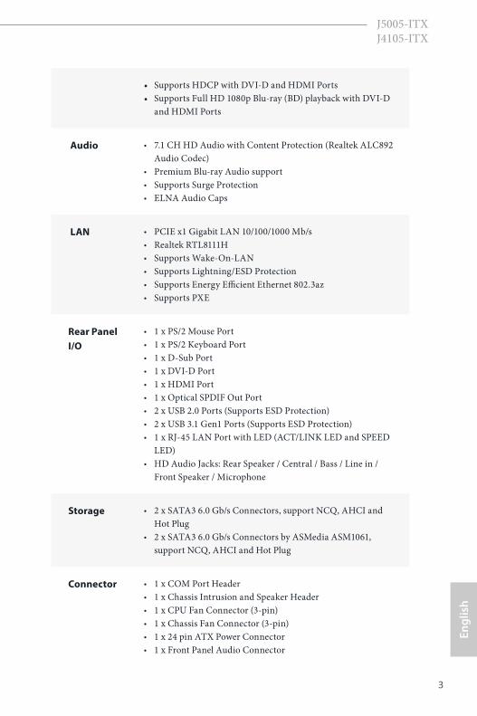
• Supports HDCP with DVI-D and HDMI Ports• Supports Full HD 1080p Blu-ray (BD) playback with DVI-D
and HDMI Ports
Audio • 7.1 CH HD Audio with Content Protection (Realtek ALC892 Audio Codec)
• Premium Blu-ray Audio support• Supports Surge Protection• ELNA Audio Caps
LAN • PCIE x1 Gigabit LAN 10/100/1000 Mb/s• Realtek RTL8111H• Supports Wake-On-LAN • Supports Lightning/ESD Protection• Supports Energy Efficient Ethernet 802.3az• Supports PXE
Rear Panel I/O
• 1 x PS/2 Mouse Port• 1 x PS/2 Keyboard Port• 1 x D-Sub Port• 1 x DVI-D Port• 1 x HDMI Port• 1 x Optical SPDIF Out Port• 2 x USB 2.0 Ports (Supports ESD Protection)• 2 x USB 3.1 Gen1 Ports (Supports ESD Protection)• 1 x RJ-45 LAN Port with LED (ACT/LINK LED and SPEED
LED)• HD Audio Jacks: Rear Speaker / Central / Bass / Line in /
Front Speaker / Microphone
Storage • 2 x SATA3 6.0 Gb/s Connectors, support NCQ, AHCI and Hot Plug
• 2 x SATA3 6.0 Gb/s Connectors by ASMedia ASM1061, support NCQ, AHCI and Hot Plug
Connector • 1 x COM Port Header• 1 x Chassis Intrusion and Speaker Header• 1 x CPU Fan Connector (3-pin)• 1 x Chassis Fan Connector (3-pin)• 1 x 24 pin ATX Power Connector• 1 x Front Panel Audio Connector
4
English
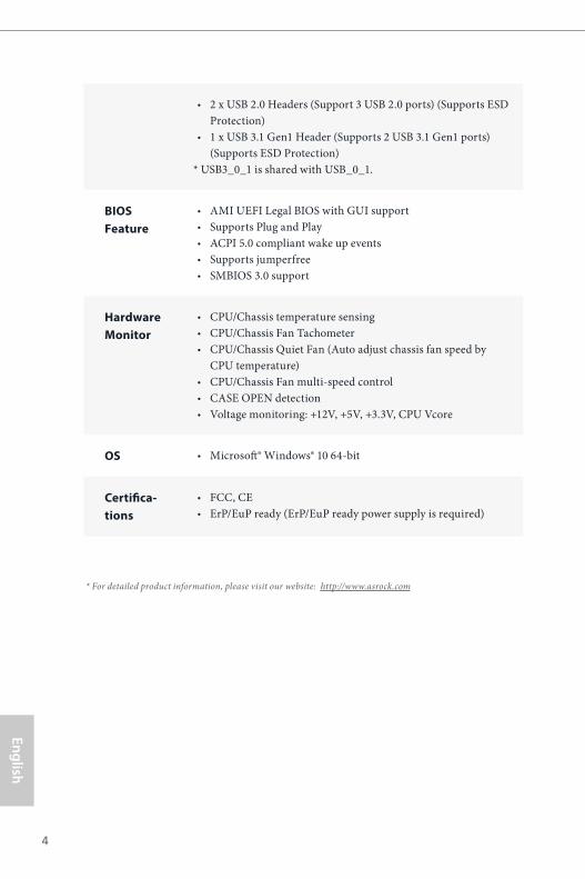
• 2 x USB 2.0 Headers (Support 3 USB 2.0 ports) (Supports ESD Protection)
• 1 x USB 3.1 Gen1 Header (Supports 2 USB 3.1 Gen1 ports) (Supports ESD Protection)
* USB3_0_1 is shared with USB_0_1.
BIOS Feature
• AMI UEFI Legal BIOS with GUI support• Supports Plug and Play• ACPI 5.0 compliant wake up events• Supports jumperfree• SMBIOS 3.0 support
Hardware Monitor
• CPU/Chassis temperature sensing• CPU/Chassis Fan Tachometer• CPU/Chassis Quiet Fan (Auto adjust chassis fan speed by
CPU temperature)• CPU/Chassis Fan multi-speed control• CASE OPEN detection• Voltage monitoring: +12V, +5V, +3.3V, CPU Vcore
OS • Microsoft® Windows® 10 64-bit
Certifica-tions
• FCC, CE• ErP/EuP ready (ErP/EuP ready power supply is required)
* For detailed product information, please visit our website: http://www.asrock.com
5
Engl
ish
J5005-ITX J4105-ITX
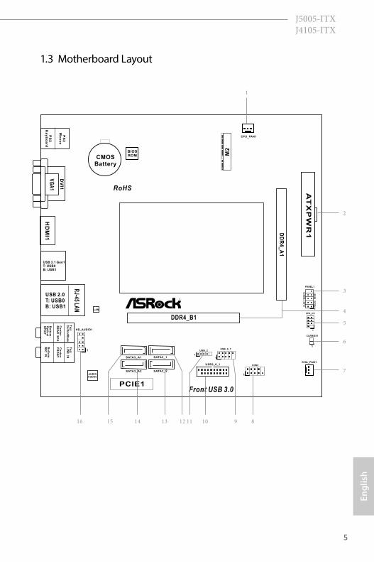
1.3 Motherboard Layout
PCIE1
AT
XP
WR
1
AUDIOCODEC
2
DD
R4
_A
1
DDR4_B1
CPU_FAN1
COM1
1
RoHS
1
HD_AUDIO1
1
4
5
11
BIOSROM
Front USB 3.0
LAN
CLRMOS1
1
USB3_0_1
141516
1
USB_0_1
10
SATA3_1SATA3_A1
7
9
RJ-45 LA
NUSB 2.0T: USB0B: USB1
PS
2K
ey
bo
ard
PS
2M
ou
se
CMOSBattery
PANEL1
1
HD
LE
D
RE
SE
T
PL
ED
P
WR
BT
N
SATA3_2SATA3_A2
1
USB_2
SPK_CI1
1H
DM
I1V
GA
1
DV
I1
USB 3.1 Gen1T: USB0B: USB1
To
p:
Cen
tral/B
ass
Ce
nte
r:R
EA
R S
PK
To
p:
LIN
E IN
Ce
nte
r:F
RO
NT
Bo
ttom
:O
ptic
al
SP
DIF
Bo
ttom
:M
IC IN
13 12
3
6
8
M2
6
English
No. Description
1 CPU Fan Connector (CPU_FAN1)
2 ATX Power Connector (ATXPWR1)
3 System Panel Header (PANEL1)
4 2 x 260-pin DDR4 SO-DIMM Slots (DDR4_A1, DDR4_B1)
5 Chassis Intrusion and Speaker Header (SPK_CI1)
6 Clear CMOS Jumper (CLRMOS1)
7 Chassis Fan Connector (CHA_FAN1)
8 COM Port Header (COM1)
9 USB 2.0 Header (USB_0_1)
10 USB 3.1 Gen1 Header (USB3_0_1)
11 USB 2.0 Header (USB_2)
12 SATA3 Connector (SATA3_1)
13 SATA3 Connector (SATA3_2)
14 SATA3 Connector (SATA3_A2)
15 SATA3 Connector (SATA3_A1)
16 Front Panel Audio Header (HD_AUDIO1)
7
Engl
ish
J5005-ITX J4105-ITX
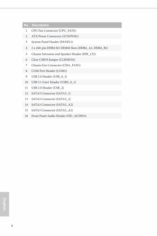
1.4 I/O Panel
No. Description No. Description
1 PS/2 Mouse Port 8 Microphone (Pink)
2 D-Sub Port 9 Optical SPDIF Out Port
3 LAN RJ-45 Port* 10 USB 2.0 Ports (USB_01)
4 Central / Bass (Orange) 11 USB 3.1 Gen1 Ports (USB3_01)
5 Rear Speaker (Black) 12 HDMI Port
6 Line In (Light Blue) 13 DVI-D Port
7 Front Speaker (Lime)** 14 PS/2 Keyboard Port
1
14 1012 1113
32
89
54
76
8
English
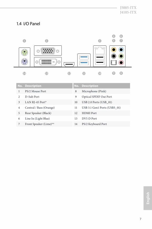
* There are two LEDs on each LAN port. Please refer to the table below for the LAN port LED indications.
Activity / Link LED Speed LED
Status Description Status DescriptionOff No Link Off 10Mbps connectionBlinking Data Activity Orange 100Mbps connectionOn Link Green 1Gbps connection
** If you use a 2-channel speaker, please connect the speaker’s plug into “Front Speaker Jack”. See the table below for connection details in accordance with the type of speaker you use.
Audio Output Channels
Front Speaker(No. 7)
Rear Speaker(No. 5)
Central / Bass(No. 4)
Line In(No. 6)
2 V -- -- --4 V V -- --6 V V V --8 V V V V
To enable Multi-Streaming, you need to connect a front panel audio cable to the front panel audio header. After restarting your computer, you will find the “Mixer” tool on your system. Please select “Mixer ToolBox” , click “Enable playback multi-streaming”, and click “ok”. Choose “2CH”, “4CH”, “6CH”, or “8CH” and then you are allowed to select “Realtek HDA Primary output” to use the Rear Speaker, Central/Bass, and Front Speaker, or select “Realtek HDA Audio 2nd output” to use the front panel audio.
ACT/LINK LED
SPEED LED
LAN Port
9
Engl
ish
J5005-ITX J4105-ITX
This is a Mini-ITX form factor motherboard. Before you install the motherboard, study the configuration of your chassis to ensure that the motherboard fits into it.
Pre-installation PrecautionsTake note of the following precautions before you install motherboard components or change any motherboard settings.
• Make sure to unplug the power cord before installing or removing the motherboard. Failure to do so may cause physical injuries to you and damages to motherboard components.
• In order to avoid damage from static electricity to the motherboard’s components, NEVER place your motherboard directly on a carpet. Also remember to use a grounded wrist strap or touch a safety grounded object before you handle the components.
• Hold components by the edges and do not touch the ICs.• Whenever you uninstall any components, place them on a grounded anti-static pad or
in the bag that comes with the components.• When placing screws to secure the motherboard to the chassis, please do not over-
tighten the screws! Doing so may damage the motherboard.
Chapter 2 Installation
10
English
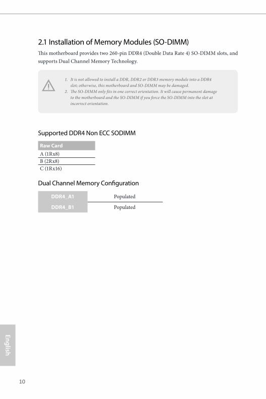
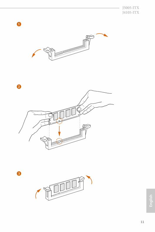
2.1 Installation of Memory Modules (SO-DIMM)This motherboard provides two 260-pin DDR4 (Double Data Rate 4) SO-DIMM slots, and supports Dual Channel Memory Technology.
Supported DDR4 Non ECC SODIMM
Raw CardA (1Rx8)B (2Rx8)C (1Rx16)
Dual Channel Memory Configuration
DDR4_A1 Populated
DDR4_B1 Populated
1. It is not allowed to install a DDR, DDR2 or DDR3 memory module into a DDR4 slot; otherwise, this motherboard and SO-DIMM may be damaged.
2. The SO-DIMM only fits in one correct orientation. It will cause permanent damage to the motherboard and the SO-DIMM if you force the SO-DIMM into the slot at incorrect orientation.
11
Engl
ish
J5005-ITX J4105-ITX
1
2
3
12
English
2.2 Expansion Slot (PCI Express Slot)There is 1 PCI Express slot on the motherboard.
PCIe slot:
PCIE1 (PCIe 2.0 x1 slot) is used for PCI Express x1 lane width cards.
Warning: To ensure better graphics compability, the BIOS is set to "boot from Onboard VGA" as default even the user install a VGA card on PCIe slot.
Before installing an expansion card, please make sure that the power supply is switched off or the power cord is unplugged. Please read the documentation of the expansion card and make necessary hardware settings for the card before you start the installation.
13
Engl
ish
J5005-ITX J4105-ITX
If you clear the CMOS, the case open may be detected. Please adjust the BIOS option “Clear Status” to clear the record of previous chassis intrusion status.
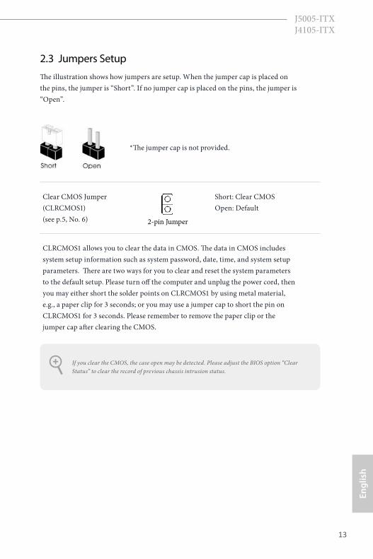
2.3 Jumpers SetupThe illustration shows how jumpers are setup. When the jumper cap is placed on the pins, the jumper is “Short”. If no jumper cap is placed on the pins, the jumper is “Open”.
Clear CMOS Jumper(CLRCMOS1)(see p.5, No. 6)
Short: Clear CMOS Open: Default
CLRCMOS1 allows you to clear the data in CMOS. The data in CMOS includes system setup information such as system password, date, time, and system setup parameters. There are two ways for you to clear and reset the system parameters to the default setup. Please turn off the computer and unplug the power cord, then you may either short the solder points on CLRCMOS1 by using metal material, e.g., a paper clip for 3 seconds; or you may use a jumper cap to short the pin on CLRCMOS1 for 3 seconds. Please remember to remove the paper clip or the jumper cap after clearing the CMOS.
2-pin Jumper
*The jumper cap is not provided.
14
English
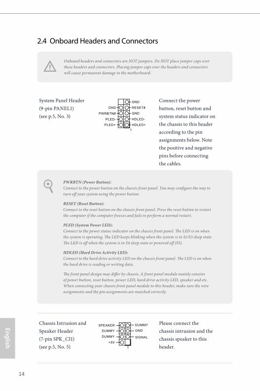
2.4 Onboard Headers and Connectors
System Panel Header(9-pin PANEL1)(see p.5, No. 3)
Connect the power button, reset button and system status indicator on the chassis to this header according to the pin assignments below. Note the positive and negative pins before connecting the cables.
Chassis Intrusion and Speaker Header(7-pin SPK_CI1)(see p.5, No. 5)
Please connect the chassis intrusion and the chassis speaker to this header.
PWRBTN (Power Button): Connect to the power button on the chassis front panel. You may configure the way to turn off your system using the power button.
RESET (Reset Button): Connect to the reset button on the chassis front panel. Press the reset button to restart the computer if the computer freezes and fails to perform a normal restart.
PLED (System Power LED): Connect to the power status indicator on the chassis front panel. The LED is on when the system is operating. The LED keeps blinking when the system is in S1/S3 sleep state. The LED is off when the system is in S4 sleep state or powered off (S5).
HDLED (Hard Drive Activity LED): Connect to the hard drive activity LED on the chassis front panel. The LED is on when the hard drive is reading or writing data.
The front panel design may differ by chassis. A front panel module mainly consists of power button, reset button, power LED, hard drive activity LED, speaker and etc. When connecting your chassis front panel module to this header, make sure the wire assignments and the pin assignments are matched correctly.
Onboard headers and connectors are NOT jumpers. Do NOT place jumper caps over these headers and connectors. Placing jumper caps over the headers and connectors will cause permanent damage to the motherboard.
GND RESET#
PWRBTN#
PLED-
PLED+
GND
HDLED-
HDLED+
1
GND
1+5V
SIGNAL
GNDDUMMY
DUMMY
SPEAKER DUMMY
15
Engl
ish
J5005-ITX J4105-ITX
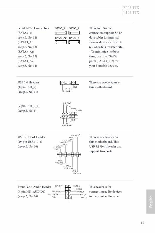
Serial ATA3 Connectors(SATA3_1: see p.5, No. 12) (SATA3_2: see p.5, No. 13)(SATA3_A1: see p.5, No. 15) (SATA3_A2: see p.5, No. 14)
These four SATA3 connectors support SATA data cables for internal storage devices with up to 6.0 Gb/s data transfer rate. * To minimize the boot time, use Intel® SATA ports (SATA3_1~2) for your bootable devices.
USB 2.0 Headers(4-pin USB_2)(see p.5, No. 11)
(9-pin USB_0_1)(see p.5, No. 9)
There are two headers on this motherboard.
USB 3.1 Gen1 Header(19-pin USB3_0_1)(see p.5, No. 10)
There is one header on this motherboard. This USB 3.1 Gen1 header can support two ports.
Front Panel Audio Header(9-pin HD_AUDIO1)(see p.5, No. 16)
This header is for connecting audio devices to the front audio panel.
1
IDIntA_P_D +
IntA_P_D -GN D
IntA_P_SSTX+IntA_P_SSTX-
GN DIntA_P_SSRX +
Vbu s
IntA_P_D +IntA_P_D -GN D
IntA_P_SSTX+IntA_P_SSTX-
GN DIntA_P_SSRX +
IntA_P_SSRX -Vbu s
IntA_P_SSRX -
DUMMYGND
GND
P+P-
USB_PWR
P+P-
USB_PWR
1
J_SENSE
OUT2_L
1
MIC_RED
OUT_RET
OUT2_R
MIC2_R
MIC2_LGND
PRESENCE#
SATA3_A1 SATA3_1
SATA3_A2 SATA3_2
1
USB_PWRP- P+
GND
16
English
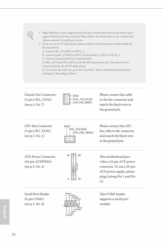
Chassis Fan Connector(3-pin CHA_FAN1)(see p.5, No. 7)
Please connect fan cable to the fan connector and match the black wire to the ground pin.
CPU Fan Connector(3-pin CPU_FAN1)(see p.5, No. 1)
Please connect the CPU fan cable to the connector and match the black wire to the ground pin.
ATX Power Connector(24-pin ATXPWR1)(see p.5, No. 4)
This motherboard pro-vides a 24-pin ATX power connector. To use a 20-pin ATX power supply, please plug it along Pin 1 and Pin 13.
Serial Port Header(9-pin COM1)(see p.5, No. 8)
This COM1 header supports a serial port module.
1. High Definition Audio supports Jack Sensing, but the panel wire on the chassis must support HDA to function correctly. Please follow the instructions in our manual and chassis manual to install your system.
2. If you use an AC’97 audio panel, please install it to the front panel audio header by the steps below: A. Connect Mic_IN (MIC) to MIC2_L. B. Connect Audio_R (RIN) to OUT2_R and Audio_L (LIN) to OUT2_L. C. Connect Ground (GND) to Ground (GND). D. MIC_RET and OUT_RET are for the HD audio panel only. You don’t need to connect them for the AC’97 audio panel. E. To activate the front mic, go to the “FrontMic” Tab in the Realtek Control panel and adjust “Recording Volume”.
12
1
24
13
GND
CPU_FAN_SPEEDFAN_VOLTAGE
CCTS#1
RRTS#1
DDSR#1
DDTR#1
RRXD1
GND
TTXD1
DDCD#1
1
RRI#1
GND
CHA_FAN_SPEEDFAN_VOLTAGE
17
Engl
ish
J5005-ITX J4105-ITX
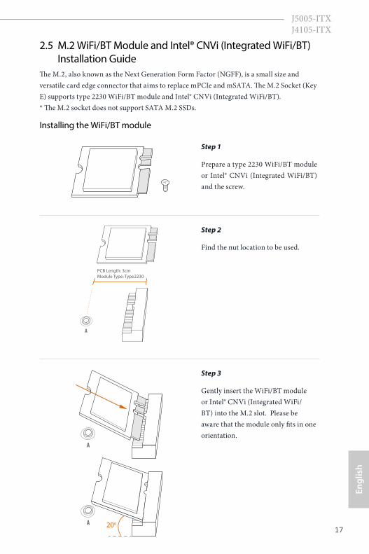
2.5 M.2 WiFi/BT Module and Intel® CNVi (Integrated WiFi/BT) Installation GuideThe M.2, also known as the Next Generation Form Factor (NGFF), is a small size and versatile card edge connector that aims to replace mPCIe and mSATA. The M.2 Socket (Key E) supports type 2230 WiFi/BT module and Intel® CNVi (Integrated WiFi/BT). * The M.2 socket does not support SATA M.2 SSDs.
Installing the WiFi/BT module
Step 1
Prepare a type 2230 WiFi/BT module or Intel® CNVi (Integrated WiFi/BT) and the screw.
PCB Length: 3cm Module Type: Type2230
A
Step 2
Find the nut location to be used.
A
A 20o
Step 3
Gently insert the WiFi/BT module or Intel® CNVi (Integrated WiFi/BT) into the M.2 slot. Please be aware that the module only fits in one orientation.
18
English
A
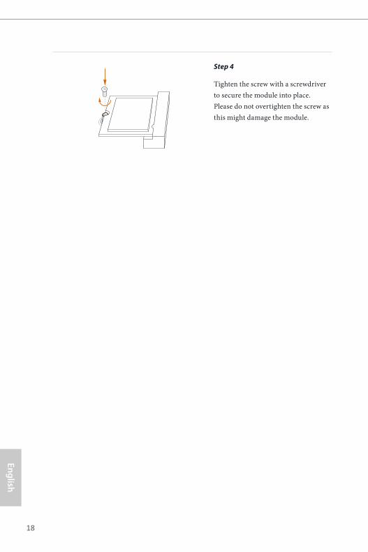
Step 4
Tighten the screw with a screwdriver to secure the module into place. Please do not overtighten the screw as this might damage the module.
19
Engl
ish
J5005-ITX J4105-ITX
Chapter 3 Software and Utilities Operation 3.1 Installing DriversThe Support CD that comes with the motherboard contains necessary drivers and useful utilities that enhance the motherboard’s features.
Running The Support CDTo begin using the support CD, insert the CD into your CD-ROM drive. The CD automatically displays the Main Menu if “AUTORUN” is enabled in your computer. If the Main Menu does not appear automatically, locate and double click on the file “ASRSETUP.EXE” in the Support CD to display the menu.
Drivers MenuThe drivers compatible to your system will be auto-detected and listed on the support CD driver page. Please click Install All or follow the order from top to bottom to install those required drivers. Therefore, the drivers you install can work properly.
Utilities MenuThe Utilities Menu shows the application software that the motherboard supports. Click on a specific item then follow the installation wizard to install it.
20
English
3.2 ASRock Live Update & APP ShopThe ASRock Live Update & APP Shop is an online store for purchasing and downloading software applications for your ASRock computer. You can quickly and easily install various apps and support utilities. With ASRock Live Update & APP Shop utility, you can optimize your system and keep your motherboard up to date simply with a few clicks.
Double-click on your desktop to access ASRock Live Update & APP Shop utility.
*You need to be connected to the Internet to download apps from the ASRock Live Update & APP Shop.
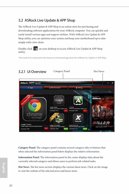
3.2.1 UI Overview
Category Panel: The category panel contains several category tabs or buttons that when selected the information panel below displays the relative information.
Information Panel: The information panel in the center displays data about the currently selected category and allows users to perform job-related tasks.
Hot News: The hot news section displays the various latest news. Click on the image to visit the website of the selected news and know more.
Information Panel
Hot NewsCategory Panel
21
Engl
ish
J5005-ITX J4105-ITX
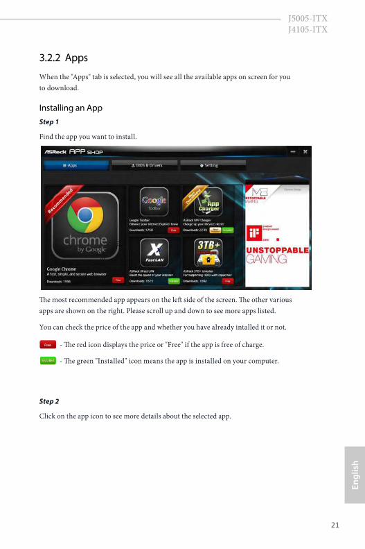
3.2.2 Apps
When the "Apps" tab is selected, you will see all the available apps on screen for you to download.
Installing an AppStep 1
Find the app you want to install.
The most recommended app appears on the left side of the screen. The other various apps are shown on the right. Please scroll up and down to see more apps listed.
You can check the price of the app and whether you have already intalled it or not.
- The red icon displays the price or "Free" if the app is free of charge.
- The green "Installed" icon means the app is installed on your computer.
Step 2
Click on the app icon to see more details about the selected app.
22
English
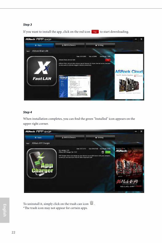
Step 3
If you want to install the app, click on the red icon to start downloading.
Step 4
When installation completes, you can find the green "Installed" icon appears on the upper right corner.
To uninstall it, simply click on the trash can icon . *The trash icon may not appear for certain apps.
23
Engl
ish
J5005-ITX J4105-ITX
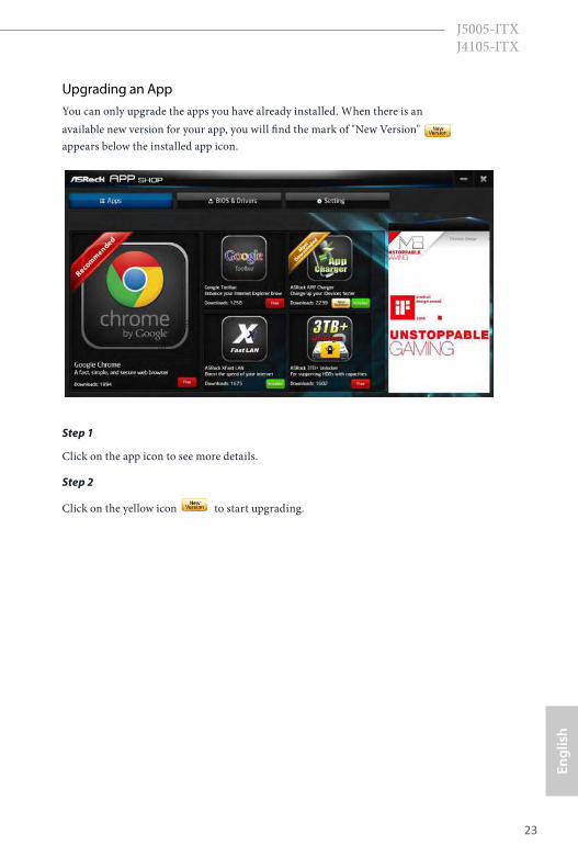
Upgrading an AppYou can only upgrade the apps you have already installed. When there is an available new version for your app, you will find the mark of "New Version" appears below the installed app icon.
Step 1
Click on the app icon to see more details.
Step 2
Click on the yellow icon to start upgrading.
24
English
3.2.3 BIOS & Drivers
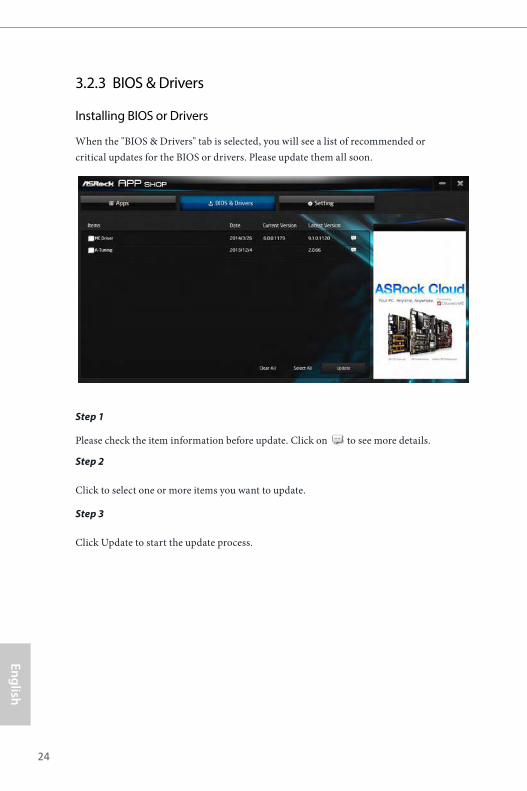
Installing BIOS or Drivers
When the "BIOS & Drivers" tab is selected, you will see a list of recommended or critical updates for the BIOS or drivers. Please update them all soon.
Step 1
Please check the item information before update. Click on to see more details.
Step 2
Click to select one or more items you want to update.
Step 3
Click Update to start the update process.
25
Engl
ish
J5005-ITX J4105-ITX
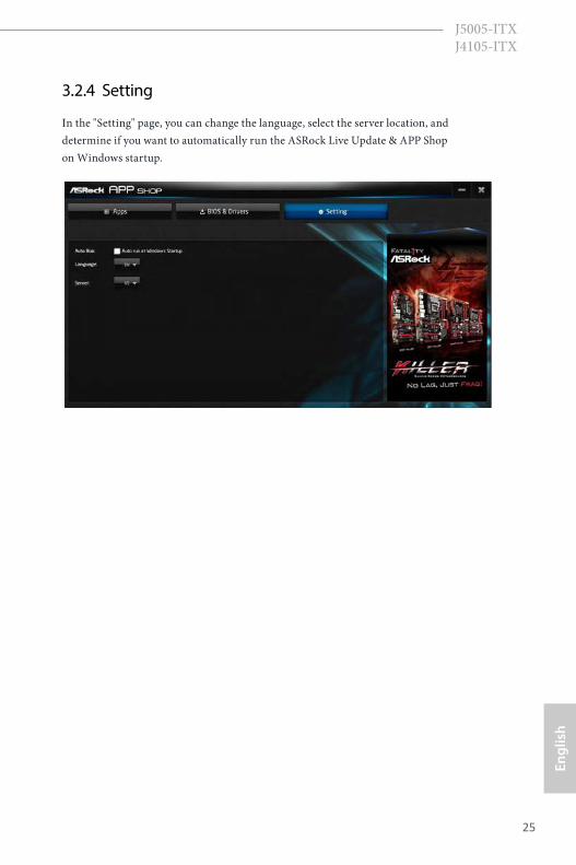
3.2.4 Setting
In the "Setting" page, you can change the language, select the server location, and determine if you want to automatically run the ASRock Live Update & APP Shop on Windows startup.
26
English
Chapter 4 UEFI SETUP UTILITY
4.1 IntroductionThis section explains how to use the UEFI SETUP UTILITY to configure your system. You may run the UEFI SETUP UTILITY by pressing <F2> or <Del> right after you power on the computer, otherwise, the Power-On-Self-Test (POST) will continue with its test routines. If you wish to enter the UEFI SETUP UTILITY after POST, restart the system by pressing <Ctl> + <Alt> + <Delete>, or by pressing the reset button on the system chassis. You may also restart by turning the system off and then back on.
4.1.1 UEFI Menu Bar
The top of the screen has a menu bar with the following selections:
Main For setting system time/date information
Advanced For advanced system configurations
Tool Useful tools
H/W Monitor Displays current hardware status
Security For security settings
Boot For configuring boot settings and boot priority
Exit Exit the current screen or the UEFI Setup Utility
Because the UEFI software is constantly being updated, the following UEFI setup screens and descriptions are for reference purpose only, and they may not exactly match what you see on your screen.
27
Engl
ish
J5005-ITX J4105-ITX
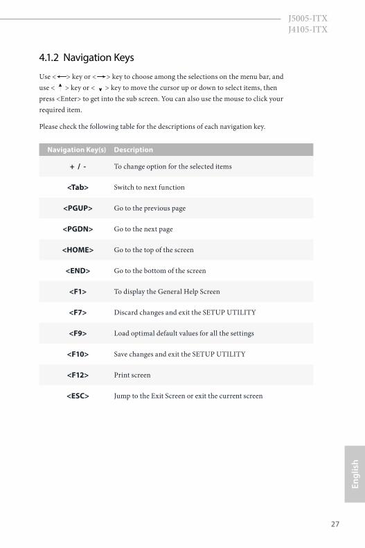
4.1.2 Navigation Keys
Use < > key or < > key to choose among the selections on the menu bar, and use < > key or < > key to move the cursor up or down to select items, then press <Enter> to get into the sub screen. You can also use the mouse to click your required item.
Please check the following table for the descriptions of each navigation key.
Navigation Key(s) Description
+ / - To change option for the selected items
<Tab> Switch to next function
<PGUP> Go to the previous page
<PGDN> Go to the next page
<HOME> Go to the top of the screen
<END> Go to the bottom of the screen
<F1> To display the General Help Screen
<F7> Discard changes and exit the SETUP UTILITY
<F9> Load optimal default values for all the settings
<F10> Save changes and exit the SETUP UTILITY
<F12> Print screen
<ESC> Jump to the Exit Screen or exit the current screen
28
English
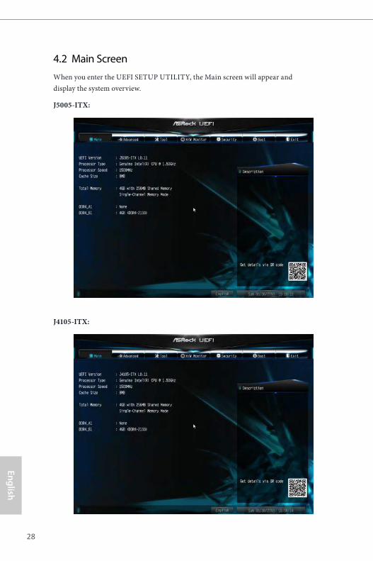
4.2 Main ScreenWhen you enter the UEFI SETUP UTILITY, the Main screen will appear and display the system overview.
J5005-ITX:
J4105-ITX:

29
Engl
ish
J5005-ITX J4105-ITX
4.3 Advanced ScreenIn this section, you may set the configurations for the following items: CPU Configuration, Chipset Configuration, Storage Configuration, Super IO Con-figuration, ACPI Configuration and USB Configuration.
Setting wrong values in this section may cause the system to malfunction.
30
English
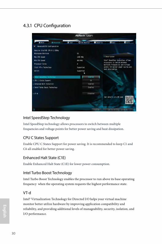
4.3.1 CPU Configuration
Intel SpeedStep TechnologyIntel SpeedStep technology allows processors to switch between multiple frequencies and voltage points for better power saving and heat dissipation.
CPU C States SupportEnable CPU C States Support for power saving. It is recommended to keep C1 and C6 all enabled for better power saving.
Enhanced Halt State (C1E)Enable Enhanced Halt State (C1E) for lower power consumption.
Intel Turbo Boost TechnologyIntel Turbo Boost Technology enables the processor to run above its base operating frequency when the operating system requests the highest performance state.
VT-dIntel® Virtualization Technology for Directed I/O helps your virtual machine monitor better utilize hardware by improving application compatibility and reliability, and providing additional levels of manageability, security, isolation, and I/O performance.
31
Engl
ish
J5005-ITX J4105-ITX
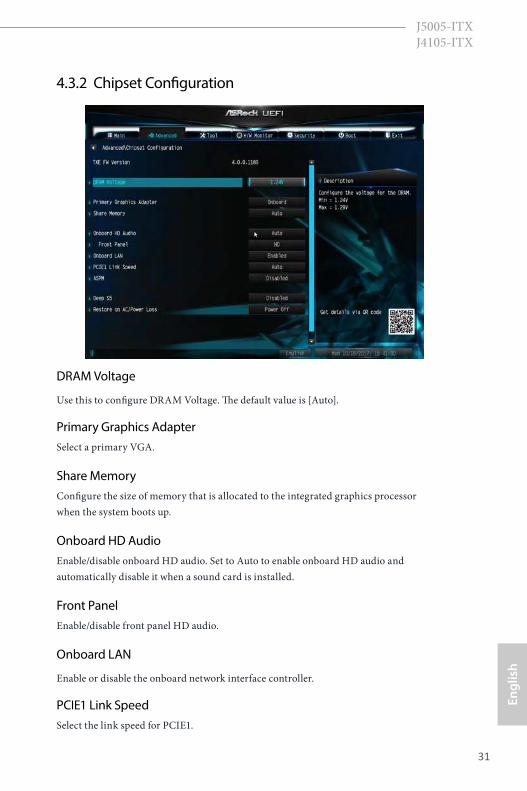
4.3.2 Chipset Configuration
DRAM Voltage
Use this to configure DRAM Voltage. The default value is [Auto].
Primary Graphics AdapterSelect a primary VGA.
Share MemoryConfigure the size of memory that is allocated to the integrated graphics processor when the system boots up.
Onboard HD AudioEnable/disable onboard HD audio. Set to Auto to enable onboard HD audio and automatically disable it when a sound card is installed.
Front PanelEnable/disable front panel HD audio.
Onboard LAN
Enable or disable the onboard network interface controller.
PCIE1 Link SpeedSelect the link speed for PCIE1.
32
English
ASPM
This option enables/disables the ASPM support.
Deep S5
Configure deep sleep mode for power saving when the computer is shut down.
Restore on AC/Power LossSelect the power state after a power failure. If [Power Off] is selected, the power will remain off when the power recovers. If [Power On] is selected, the system will start to boot up when the power recovers.
33
Engl
ish
J5005-ITX J4105-ITX
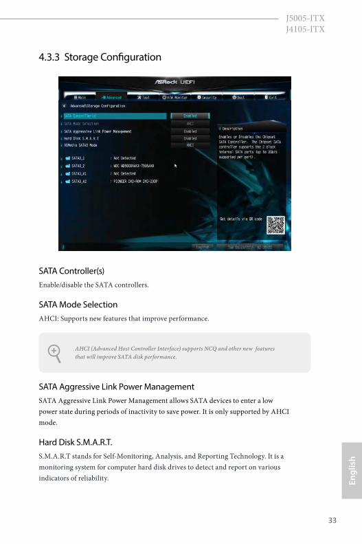
4.3.3 Storage Configuration
SATA Controller(s)Enable/disable the SATA controllers.
SATA Mode SelectionAHCI: Supports new features that improve performance.
SATA Aggressive Link Power ManagementSATA Aggressive Link Power Management allows SATA devices to enter a low power state during periods of inactivity to save power. It is only supported by AHCI mode.
Hard Disk S.M.A.R.T.S.M.A.R.T stands for Self-Monitoring, Analysis, and Reporting Technology. It is a monitoring system for computer hard disk drives to detect and report on various indicators of reliability.
AHCI (Advanced Host Controller Interface) supports NCQ and other new features that will improve SATA disk performance.
34
English
ASMedia SATA3 ModeAHCI: Supports new features that improve performance.
35
Engl
ish
J5005-ITX J4105-ITX
4.3.4 Super IO Configuration
Serial Port 1Enable or disable the Serial port 1.
Serial Port AddressSelect the address of the Serial port.
36
English
4.3.5 ACPI Configuration
Suspend to RAMIt is recommended to select auto for ACPI S3 power saving.
ACPI HPET TableEnable the High Precision Event Timer for better performance and to pass WHQL tests.
PS/2 Keyboard Power OnAllow the system to be waked up by a PS/2 Keyboard.
PCIE Device Power OnAllow the system to be waked up by a PCIE device and enable wake on LAN.
Ring-In Power On
Allow the system to be waked up by onboard COM port modem Ring-In signals.
RTC Alarm Power OnAllow the system to be waked up by the real time clock alarm. Set it to By OS to let it be handled by your operating system.
37
Engl
ish
J5005-ITX J4105-ITX
USB Keyboard/Remote Power OnAllow the system to be waked up by an USB keyboard or remote controller.
USB Mouse Power OnAllow the system to be waked up by an USB mouse.
38
English
4.3.6 USB Configuration
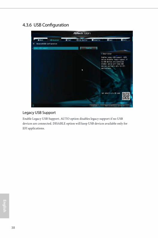
Legacy USB SupportEnable Legacy USB Support. AUTO option disables legacy support if no USB devices are connected. DISABLE option will keep USB devices available only for EFI applications.
39
Engl
ish
J5005-ITX J4105-ITX
4.4 Tools
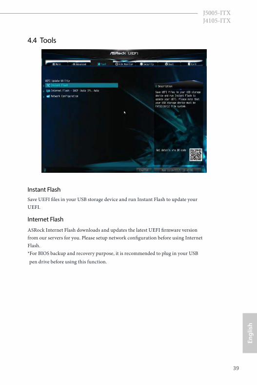
Instant FlashSave UEFI files in your USB storage device and run Instant Flash to update your UEFI.
Internet Flash
ASRock Internet Flash downloads and updates the latest UEFI firmware version from our servers for you. Please setup network configuration before using Internet Flash. *For BIOS backup and recovery purpose, it is recommended to plug in your USB pen drive before using this function.
40
English
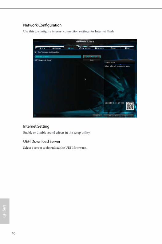
Network ConfigurationUse this to configure internet connection settings for Internet Flash.
Internet SettingEnable or disable sound effects in the setup utility.
UEFI Download ServerSelect a server to download the UEFI firmware.
41
Engl
ish
J5005-ITX J4105-ITX
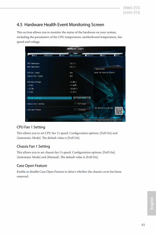
4.5 Hardware Health Event Monitoring ScreenThis section allows you to monitor the status of the hardware on your system, including the parameters of the CPU temperature, motherboard temperature, fan speed and voltage.
CPU Fan 1 SettingThis allows you to set CPU fan 1’s speed. Configuration options: [Full On] and [Automatic Mode]. The default value is [Full On].
Chassis Fan 1 SettingThis allows you to set chassis fan 1’s speed. Configuration options: [Full On], [Automatic Mode] and [Manual]. The default value is [Full On].
Case Open FeatureEnable or disable Case Open Feature to detect whether the chassis cover has been removed.
42
English
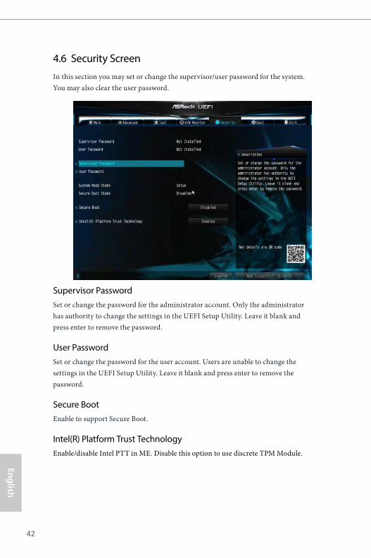
4.6 Security ScreenIn this section you may set or change the supervisor/user password for the system. You may also clear the user password.
Supervisor PasswordSet or change the password for the administrator account. Only the administrator has authority to change the settings in the UEFI Setup Utility. Leave it blank and press enter to remove the password.
User PasswordSet or change the password for the user account. Users are unable to change the settings in the UEFI Setup Utility. Leave it blank and press enter to remove the password.
Secure BootEnable to support Secure Boot.
Intel(R) Platform Trust TechnologyEnable/disable Intel PTT in ME. Disable this option to use discrete TPM Module.
43
Engl
ish
J5005-ITX J4105-ITX
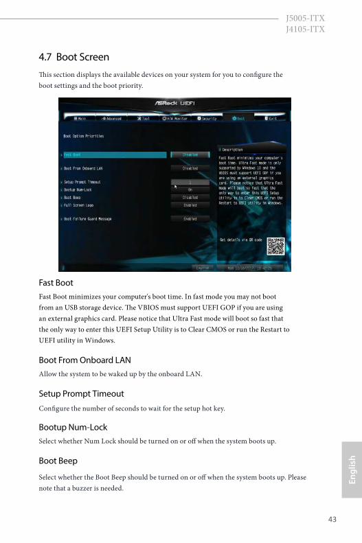
4.7 Boot ScreenThis section displays the available devices on your system for you to configure the boot settings and the boot priority.
Fast BootFast Boot minimizes your computer's boot time. In fast mode you may not boot from an USB storage device. The VBIOS must support UEFI GOP if you are using an external graphics card. Please notice that Ultra Fast mode will boot so fast that the only way to enter this UEFI Setup Utility is to Clear CMOS or run the Restart to UEFI utility in Windows.
Boot From Onboard LANAllow the system to be waked up by the onboard LAN.
Setup Prompt Timeout
Configure the number of seconds to wait for the setup hot key.
Bootup Num-LockSelect whether Num Lock should be turned on or off when the system boots up.
Boot Beep
Select whether the Boot Beep should be turned on or off when the system boots up. Please note that a buzzer is needed.
44
English
Full Screen LogoEnable to display the boot logo or disable to show normal POST messages.
Boot Failure Guard MessageIf the computer fails to boot for a number of times the system automatically restores the default settings.
45
Engl
ish
J5005-ITX J4105-ITX
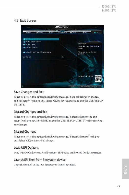
4.8 Exit Screen
Save Changes and ExitWhen you select this option the following message, “Save configuration changes and exit setup?” will pop out. Select [OK] to save changes and exit the UEFI SETUP UTILITY.
Discard Changes and ExitWhen you select this option the following message, “Discard changes and exit setup?” will pop out. Select [OK] to exit the UEFI SETUP UTILITY without saving any changes.
Discard ChangesWhen you select this option the following message, “Discard changes?” will pop out. Select [OK] to discard all changes.
Load UEFI DefaultsLoad UEFI default values for all options. The F9 key can be used for this operation.
Launch EFI Shell from filesystem deviceCopy shellx64.efi to the root directory to launch EFI Shell.
Contact Information
If you need to contact ASRock or want to know more about ASRock, you’re welcome to visit ASRock’s website at http://www.asrock.com; or you may contact your dealer for further information. For technical questions, please submit a support request form at https://event.asrock.com/tsd.asp
ASRock Incorporation2F., No.37, Sec. 2, Jhongyang S. Rd., Beitou District,
Taipei City 112, Taiwan (R.O.C.)
ASRock EUROPE B.V.Bijsterhuizen 11-11
6546 AR Nijmegen
The Netherlands
Phone: +31-24-345-44-33
Fax: +31-24-345-44-38
ASRock America, Inc.13848 Magnolia Ave, Chino, CA91710
U.S.A.
Phone: +1-909-590-8308
Fax: +1-909-590-1026
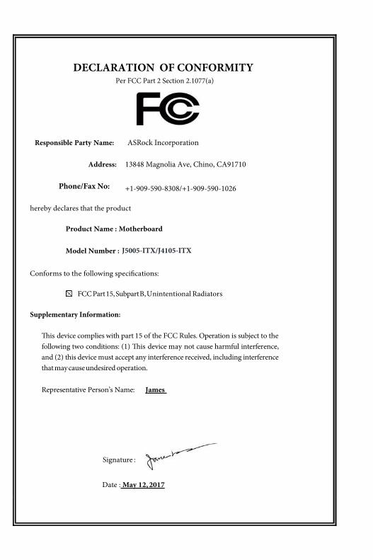
DECLARATION OF CONFORMITY
Per FCC Part 2 Section 2.1077(a)
Responsible Party Name: ASRock Incorporation
Address: 13848 Magnolia Ave, Chino, CA91710
+1-909-590-8308/+1-909-590-1026
Phone/Fax No:
hereby declares that the product
Product Name : Motherboard
Model Number :
Conforms to the following speci�cations:
FCC Part 15, Subpart B, Unintentional Radiators
Supplementary Information:
�is device complies with part 15 of the FCC Rules. Operation is subject to the following two conditions: (1) �is device may not cause harmful interference, and (2) this device must accept any interference received, including interference that may cause undesired operation. Representative Person’s Name: James
Signature :
Date : May 12, 2017
J5005-ITX/J4105-ITX

EU Declaration of Conformity For the following equipment:
Motherboard(Product Name)
J5005-ITX/J4105-ITX/ ASRock(Model Designation / Trade Name)
ASRock Incorporation(Manufacturer Name)
2F., No.37, Sec. 2, Jhongyang S. Rd., Beitou District, Taipei City 112, Taiwan (R.O.C.)(Manufacturer Address)
ASRock EUROPE B.V.(Company Name)
Bijsterhuizen 1111 6546 AR Nijmegen The Netherlands(Company Address)
Person responsible for making this declaration:
(Name, Surname)A.V.P(Position / Title)January 9, 2017(Date)
P/N: 15G062063000AK V1.0
EMC —Directive 2014/30/EU (from April 20th, 2016) ☐ EN 55022:2010/AC:2011 Class B EN 55024:2010/A1:2015
EN 55032:2012+AC:2013 Class B EN 61000-3-3:2013 EN 61000-3-2:2014
LVD —Directive 2014/35/EU (from April 20th, 2016) EN 60950-1 : 2011+ A2: 2013 ☐☐ EN 60950-1 : 2006/A12: 2011
RoHS — Directive 2011/65/EU CE marking
(EU conformity marking)
☐


![1[1].00060 A - Flexmate K500 Service Manual New Version 2 ... · warranties, express or implied, or statutory, including but not limited to the implied warranties of merchantability](https://img.pdfslide.us/doc/110x75/60292420e6bf5616904c5710/1100060-a-flexmate-k500-service-manual-new-version-2-warranties-express.jpg)