Embed Size (px)
Citation preview


Version 1.0
Published November 2013
Copyright©2013 ASRock INC. All rights reserved.
Copyright Notice:
No part of this documentation may be reproduced, transcribed, transmitted, or translated in any language, in any form or by any means, except duplication of documentation by the purchaser for backup purpose, without written consent of ASRock Inc.
Products and corporate names appearing in this documentation may or may not be registered trademarks or copyrights of their respective companies, and are used only for identiication or explanation and to the owners’ beneit, without intent to
infringe.
Disclaimer:
Speciications and information contained in this documentation are furnished for informational use only and subject to change without notice, and should not be constructed as a commitment by ASRock. ASRock assumes no responsibility for any errors or omissions that may appear in this documentation.
With respect to the contents of this documentation, ASRock does not provide warranty of any kind, either expressed or implied, including but not limited to the implied warranties or conditions of merchantability or itness for a particular purpose.
In no event shall ASRock, its directors, oicers, employees, or agents be liable for any indirect, special, incidental, or consequential damages (including damages for loss of proits, loss of business, loss of data, interruption of business and the like), even if ASRock has been advised of the possibility of such damages arising from any defect or error in the documentation or product.
his device complies with Part 15 of the FCC Rules. Operation is subject to the following two conditions: (1) this device may not cause harmful interference, and (2) this device must accept any interference received, including interference that
may cause undesired operation.
CALIFORNIA, USA ONLYhe Lithium battery adopted on this motherboard contains Perchlorate, a toxic substance controlled in Perchlorate Best Management Practices (BMP) regulations passed by the California Legislature. When you discard the Lithium battery in California, USA, please follow the related regulations in advance.“Perchlorate Material-special handling may apply, see www.dtsc.ca.gov/hazardouswaste/perchlorate”
ASRock Website: http://www.asrock.com

Manufactured under license under U.S. Patent Nos: 5,956,674; 5,974,380; 6,487,535;
7,003,467 & other U.S. and worldwide patents issued & pending. DTS, the Symbol, &
DTS and the Symbol together is a registered trademark & DTS Connect, DTS Interactive,
DTS Neo:PC are trademarks of DTS, Inc. Product includes sotware.
© DTS, Inc., All Rights Reserved.

Who knew that at age 19, I would be a World Champion PC gamer. When I was 13, I actually
played competitive billiards in professional tournaments and won four or ive games of guys
who played at the highest level. I actually thought of making a career of it, but at that young
age situations change rapidly. Because I’ve been blessed with great hand-eye coordination and
a grasp of mathematics (an important element in video gaming) I gravitated to that activity.
GOING PRO
I started professional gaming in 1999 when I entered the CPL (Cyberathlete Professional
League) tournament in Dallas and won $4,000 for coming in third place. Emerging as one
of the top players in the United States, a company interested in sponsoring me lew me to
Sweden to compete against the top 12 players in the world. I won 18 straight games, lost
none, and took irst place, becoming the number one ranked Quake III player in the world
in the process. Two months later I followed that success by traveling to Dallas and defending
my title as the world’s best Quake III player, winning the $40,000 grand prize. From there
I entered competitions all over the world, including Singapore, Korea, Germany, Australia,
Holland and Brazil in addition to Los Angeles, New York and St. Louis.
WINNING STREAKI was excited to showcase my true gaming skills when defending my title as CPL
Champion of the year at the CPL Winter 2001 because I would be competing in a totally
diferent irst person shooter (fps) game, Alien vs. Predator II. I won that competition and
walked away with a new car. he next year I won the same title playing Unreal Tournament
2003, becoming the only three-time CPL champion of the year. And I did it playing a
different game each year, something no one else has ever done and a feat of which I am
extremely proud.
At QuakeCon 2002, I faced of against my rival ZeRo4 in one of the most highly
anticipated matches of the year, winning in a 14 to (-1) killer victory. Competing at Quakecon
2004, I became the World’s 1st Doom3 Champion by defeating Daler in a series of very
challenging matches and earning $25,000 for the victory.
Since then Fatal1ty has traveled the globe to compete against the best in the world, winning
prizes and acclaim, including the 2005 CPL World Tour Championship in New York City for
a $150,000 irst place triumph. In August 2007, Johnathan was awarded the irst ever Lifetime
Achievement Award in the four year history of the eSports-Award for “showing exceptional
sportsmanship, taking part in shaping eSports into what it is today and for being the prime
representative of this young sport. He has become the igurehead for eSports worldwide”.
Fatal1ty Story

LIVIN’ LARGESince my irst big tournament wins, I have been a “Professional Cyberathlete”, traveling the
world and livin’ large with lots of International media coverage on outlets such as MTV,
ESPN and a 60 Minutes segment on CBS to name only a few. It's unreal - it's crazy. I’m living
a dream by playing video games for a living. I’ve always been athletic and took sports like
hockey and football very seriously, working out and training hard. his discipline helps me
become a better gamer and my drive to be the best has opened the doors necessary to become
a professional.
A DREAMNow, another dream is being realized – building the ultimate gaming computer, made
up of the best parts under my own brand. Quality hardware makes a huge difference in
competitions…a couple more frames per second and everything gets really nice. It’s all about
getting the computer processing faster and allowing more luid movement around the maps.
My vision for Fatal1ty hardware is to allow gamers to focus on the game without worrying
about their equipment, something I’ve preached since I began competing. I don’t want to
worry about my equipment. I want to be there – over and done with - so I can focus on
the game. I want it to be the fastest and most stable computer equipment on the face of the
planet, so quality is what Fatal1ty Brand products represent.
Johnathan “Fatal1ty” Wendel
he Fatal1ty name, Fatal1ty logos and the Fatal1ty likeness are registered trademarks of Fatal1ty, Inc., and are used
under license. © 2013 Fatal1ty, Inc. All rights reserved. All other trademarks are the property of their respective
owners.

Contents
Chapter 1 Introduction 1
1.1 Package Contents 1
1.2 Speciications 2
1.3 Unique Features 6
1.4 Motherboard Layout 9
1.5 I/O Panel 11
Chapter 2 Installation 13
2.1 Installing the CPU 14
2.2 Installing the CPU Fan and Heatsink 16
2.3 Installing Memory Modules (DIMM) 17
2.4 Expansion Slots (PCI Express Slots) 19
2.5 Jumpers Setup 20
2.6 Onboard Headers and Connectors 21
2.7 SLITM
and Quad SLITM
Operation Guide 26
2.7.1 Installing Two SLITM
-Ready Graphics Cards 26
2.7.2 Driver Installation and Setup 28
2.8 CrossFireXTM
, 3-Way CrossFireXTM
and Quad CrossFireXTM
Operation Guide 29
2.8.1 Installing Two CrossFireXTM
-Ready Graphics Cards 29
2.8.2 Installing Three CrossFireXTM
-Ready Graphics Cards 30
2.8.3 Driver Installation and Setup 31
2.9 M.2_SSD (NGFF) Module Installation Guide 32

Chapter 3 Software and Utilities Operation 34
3.1 Installing Drivers 34
3.2 F-Stream 35
3.3 Killer Network Manager 39
3.3.1 Installing Killer Network Manager 39
3.3.2 Using Killer Network Manager 39
3.4 Start8 42
3.5 XSplit Broadcaster 45
3.5.1 Live Streaming Your Gameplay 45
3.5.2 Recording Your Gameplay 48
Chapter 4 UEFI SETUP UTILITY 49
4.1 Introduction 49
4.1.1 UEFI Menu Bar 49
4.1.2 Navigation Keys 50
4.2 Main Screen 51
4.3 OC Tweaker Screen 52
4.4 Advanced Screen 57
4.4.1 CPU Coniguration 58
4.4.2 North Bridge Coniguration 60
4.4.3 South Bridge Coniguration 61
4.4.4 Storage Coniguration 62
4.4.5 Super IO Coniguration 64
4.4.6 ACPI Coniguration 65
4.4.7 USB Coniguration 67

•••••••
4.4.8 Trusted Computing 68
4.5 Tools 69
4.6 Hardware Health Event Monitoring Screen 72
4.7 Boot Screen 73
4.8 Security Screen 75
4.9 Exit Screen 76

Fatal1ty 990FX Killer Series
1
En
gli
sh
Chapter 1 Introduction
hank you for purchasing ASRock Fatal1ty 990FX Killer Series motherboard, a
reliable motherboard produced under ASRock’s consistently stringent quality
control. It delivers excellent performance with robust design conforming to
ASRock’s commitment to quality and endurance.
In this manual, Chapter 1 and 2 contains the introduction of the motherboard
and step-by-step installation guides. Chapter 3 contains the operation guide of the
sotware and utilities. Chapter 4 contains the coniguration guide of the BIOS setup.
1.1 Package Contents
• ASRock Fatal1ty 990FX Killer Series Motherboard (ATX Form Factor)
• ASRock Fatal1ty 990FX Killer Series Quick Installation Guide
• ASRock Fatal1ty 990FX Killer Series Support CD
• 4 x Serial ATA (SATA) Data Cables (Optional)
• 1 x I/O Panel Shield
• 1 x ASRock SLI_Bridge_2S Card
• 1 x M.2_SSD (NGFF) Socket 3 Screw
Because the motherboard speciications and the BIOS sotware might be updated, the
content of this manual will be subject to change without notice. In case any modiica-
tions of this manual occur, the updated version will be available on ASRock’s website
without further notice. If you require technical support related to this motherboard,
please visit our website for speciic information about the model you are using. You
may ind the latest VGA cards and CPU support list on ASRock’s website as well.
ASRock website http://www.asrock.com.

2
En
glish
1.2 Speciications
Platform • ATX Form Factor
• Premium Gold Capacitor design (100% Japan-made high-
quality conductive polymer capacitors)
A-Style • Purity SoundTM
Gaming
Armor
CPU Power
• Hi-Density Power Connector
VGA Card
• 15μGold Finger in VGA PCIe Slots (PCIE2/PCIE3)
• SLI/CrossFireX Power Connector
Internet
• Qualcomm® Atheros® KillerTM LAN
Audio
• Purity SoundTM
CPU • Supports Socket AM3+ processors
• Supports Socket AM3 processors: AMD PhenomTM II X6
/ X4 / X3 / X2 (except 920 / 940) / Athlon II X4 / X3 / X2 /
Sempron processors
• Supports 8-Core CPU
• Supports UCC feature (Unlock CPU Core)
• Digi Power design
• 8 + 2 Power Phase design
• Supports CPU up to 140W
• Supports AMD's Cool 'n' Quiet Technology
• FSB 2600 MHz (5.2 GT/s)
• Supports Untied Overclocking Technology
• Supports Hyper-Transport 3.0 (HT 3.0) Technology
Chipset • Northbridge: AMD 990FX
• Southbridge: AMD SB950
Memory • Dual Channel DDR3 Memory Technology
• 4 x DDR3 DIMM Slots
• Supports DDR3 2450(OC)/2100(OC)/1600/1333/1066 non-
ECC, un-bufered memory (see CAUTION1)

Fatal1ty 990FX Killer Series
3
En
gli
sh
• Max. capacity of system memory: 64GB (see CAUTION2)
• Supports Intel® Extreme Memory Proile (XMP) 1.3 / 1.2
• Supports AMD Memory Proile (AMP)
Expansion
Slot
• 3 x PCI Express 2.0 x16 Slots (PCIE2/PCIE3 @ x16 mode;
PCIE5 @ x4 mode)
• 2 x PCI Express 2.0 x1 Slots
• Supports AMD Quad CrossFireXTM, 3-Way CrossFireXTM and
CrossFireXTM
• Supports NVIDIA® Quad SLITM and SLITM
Audio • 7.1 CH HD Audio with Content Protection (Realtek ALC1150
Audio Codec)
• Premium Blu-ray Audio Support
• Supports Purity SoundTM
- 115dB SNR DAC with Diferential Ampliier
- TI® NE5532 Premium Headset Ampliier (Supports up to
600 ohm headsets)
- Direct Drive Technology
- EMI Shielding Cover
- PCB Isolate Shielding
• Supports DTS Connect
LAN • PCIE x1 Gigabit LAN 10/100/1000 Mb/s
• Qualcomm® Atheros® KillerTM E2200 Series
• Supports Wake-On-LAN
• Supports Energy Eicient Ethernet 802.3az
• Supports PXE
Rear Panel
I/O
• 1 x PS/2 Mouse Port
• 1 x PS/2 Keyboard Port
• 1 x Optical SPDIF Out Port
• 5 x USB 2.0 Ports
• 1 x Fatal1ty Mouse Port (USB 2.0)
• 4 x USB 3.0 Ports (ASMedia Hub)
• 1 x eSATA3 Connector

4
En
glish
• 1 x RJ-45 LAN Port with LED (ACT/LINK LED and SPEED
LED)
• HD Audio Jacks: Rear Speaker / Central / Bass / Line in /
Front Speaker / Microphone
Storage • 5 x SATA3 6.0 Gb/s Connectors, support RAID (RAID 0,
RAID 1, RAID 0+1, JBOD and RAID 5), NCQ, AHCI and
Hot Plug
• 1 x M.2_SSD (NGFF) Socket 3, supports M.2 SATA3 6.0
Gb/s module and M.2 PCI Express module up to Gen2 x2 (10
Gb/s) (M.2_SSD (NGFF) Socket 3 is shared with the eSATA3
connector)
Connector • 1 x IR Header
• 1 x COM Port Header
• 1 x TPM Header
• 1 x Power LED Header
• 2 x CPU Fan Connectors (1 x 4-pin, 1 x 3-pin)
• 3 x Chassis Fan Connectors (1 x 4-pin, 2 x 3-pin)
• 1 x Power Fan Connector (3-pin)
• 1 x 24 pin ATX Power Connector
• 1 x 8 pin 12V Power Connector (Hi-Density Power
Connector)
• 1 x SLI/XFire Power Connector (see CAUTION3)
• 1 x Front Panel Audio Connector
• 1 x SPDIF Out Connector
• 2 x USB 2.0 Headers (Support 4 USB 2.0 ports)
• 1 x Vertical Type A USB 3.0
• 1 x USB 3.0 Header by Etron EJ188 (Supports 2 USB 3.0 ports)
BIOS
Feature
• 32Mb AMI UEFI Legal BIOS with with GUI support
• Supports “Plug and Play”
• ACPI 1.1 Compliant wake up events
• Supports jumperfree
• SMBIOS 2.3.1 support
• CPU, DRAM, NB, HT, CPU VDDA, PCIE VDDA, CPU NB
Voltage multi-adjustment

Fatal1ty 990FX Killer Series
5
En
gli
sh
Support
CD
• Drivers, Utilities, AntiVirus Sotware (Trial Version), Google
Chrome Browser and Toolbar, Start8 (30 days trial), XSplit,
Killer Network Manager
Hardware
Monitor
• CPU/Chassis temperature sensing
• CPU/Chassis/Power Fan Tachometer
• CPU/Chassis Quiet Fan (Auto adjust fan speed by CPU tem-
perature)
• CPU/Chassis Fan multi-speed control
• Voltage monitoring: +12V, +5V, +3.3V, CPU Vcore Voltage
OS • Microsot® Windows® 10 64-bit / 8.1 32-bit / 8.1 64-bit / 8 32-bit /
8 64-bit / 7 32-bit / 7 64-bit
Certiica-
tions
• FCC, CE, WHQL
• ErP/EuP ready (ErP/EuP ready power supply is required)
* For detailed product information, please visit our website: http://www.asrock.com
Please realize that there is a certain risk involved with overclocking, including adjust-
ing the setting in the BIOS, applying Untied Overclocking Technology, or using third-
party overclocking tools. Overclocking may afect your system’s stability, or even cause
damage to the components and devices of your system. It should be done at your own
risk and expense. We are not responsible for possible damage caused by overclocking.
1. Whether 2450/2100MHz memory speed is supported depends on the AM3/AM3+
CPU you adopt. If you want to adopt DDR3 2450/2100 memory module on this
motherboard, please refer to the memory support list on our website for the compatible
memory modules. ASRock website: http://www.asrock.com
2. Due to the operating system limitation, the actual memory size may be less than 4GB
for the reservation for system usage under Windows® 8 / 7. For Windows® 64-bit OS
with 64-bit CPU, there is no such limitation. You can use ASRock XFast RAM to
utilize the memory that Windows® cannot use.
3. Please plug the power cable to the SLI/XFire power connector only when you install
three or more VGA cards.

6
En
glish
1.3 Unique Features
ASRock F-Stream
F-Stream is an all-in-one tool to ine-tune diferent system functions in a user-
friendly interface, it includes Hardware Monitor, Fan Control, Overclocking,
Fatal1ty Mouse Port, Energy Saving and XFast RAM.
ASRock Instant Boot
ASRock Instant Boot allows you to turn on your PC in just a few seconds, provides a
much more eicient way to save energy, time, money, and improves system running
speed for your system. It leverages the S3 and S4 ACPI features which normally
enable the Sleep/Standby and Hibernation modes in Windows® to shorten boot
up time. By calling S3 and S4 at speciic timing during the shutdown and startup
process, Instant Boot allows you to enter your Windows® desktop in a few seconds.
ASRock Instant Flash
ASRock Instant Flash is a BIOS lash utility embedded in Flash ROM. his conve-
nient BIOS update tool allows you to update the system BIOS in a few clicks without
preparing an additional loppy diskette or other complicated lash utility. Just save
the new BIOS ile to your USB storage and launch this tool by pressing <F6> or
<F2> during POST to enter the BIOS setup menu to access ASRock Instant Flash.
Please be noted that the USB lash drive or hard drive must use FAT32/16/12 ile
system.
ASRock APP Charger
Simply by installing the ASRock APP Charger makes your iPhone/iPad/iPod Touch
charge up to 40% faster than before on your computer. ASRock APP Charger allows
you to quickly charge many Apple devices simultaneously and even supports
continuous charging when your PC enters into Standby mode (S1), Suspend to RAM
(S3), hibernation mode (S4) or power of (S5).
ASRock XFast RAM
ASRock XFast RAM is included in F-Stream. It fully utilizes the memory space that
cannot be used under Windows® 32-bit operating systems. ASRock XFast RAM
shortens the loading time of previously visited websites, making web suring faster
than ever. And it also boosts the speed of Adobe Photoshop 5 times faster. Another
advantage of ASRock XFast RAM is that it reduces the frequency of accessing your
SSDs or HDDs in order to extend their lifespan.

Fatal1ty 990FX Killer Series
7
En
gli
sh
ASRock Crashless BIOS
ASRock Crashless BIOS allows users to update their BIOS without fear of failing. If
power loss occurs during the BIOS updating process, ASRock Crashless BIOS will
automatically inish the BIOS update procedure ater regaining power. Please note
that BIOS iles need to be placed in the root directory of your USB disk. Only USB 2.0
ports support this feature.
ASRock OMG (Online Management Guard)
Administrators are able to establish an internet curfew or restrict internet access
at speciied times via OMG. You may schedule the starting and ending hours of
internet access granted to other users. In order to prevent users from bypassing
OMG, guest accounts without permission to modify the system time are required.
ASRock Internet Flash
ASRock Internet Flash downloads and updates the latest UEFI irmware version
from our servers for you without entering Windows® OS. Please setup network
coniguration before using Internet Flash.
ASRock UEFI System Browser
ASRock System Browser shows the overview of your current PC and the devices
connected.
ASRock UEFI Tech Service
Contact ASRock Tech Service by sending a support request from the UEFI setup
utility if you are having trouble with your personal computer. Users may try to
choose the category of the issue they have encountered, describe the problem in
detail, and then attach an optional picture or log ile for our technical support team.
ASRock Dehumidiier Function
Users may prevent motherboard damages due to dampness by enabling
“Dehumidiier Function”. When enabling Dehumidiier Function, the computer
will power on automatically to dehumidify the system ater entering S4/S5 state.
ASRock Easy RAID Installer
ASRock Easy RAID Installer can help you to copy the RAID driver from the
support CD to your USB storage device. Ater copying the RAID driver to your
USB storage device, please change “SATA Mode” to “RAID”, then you can start
installing the OS in RAID mode.

8
En
glish
ASRock Easy Driver Installer
For users that don’t have an optical disk drive to install the drivers from our support
CD, Easy Driver Installer is a handy tool in the UEFI that installs the LAN driver
to your system via an USB storage device, then downloads and installs the other
required drivers automatically.
ASRock Fast Boot
With ASRock’s exclusive Fast Boot technology, it takes less than 1.5 seconds to
logon to Windows 8 from a cold boot. No more waiting! he speedy boot will
completely change your user experience and behavior.
ASRock X-Boost
ASRock’s X-Boost Technology is a smart auto-overclocking function and is
brilliantly designed to unlock the hidden power of your CPUs. Simply press
“X” when turning on the PC, X-Boost will automatically overclock the relative
components to get up to 15.77% performance boost! With the smart X-Boost,
overclocking CPU can become a near one-button process. * he functionality of
“Unlock CPU Cores” feature might vary by diferent processors.
ASRock Restart to UEFI
Windows® 8 brings the ultimate boot up experience. he lightning boot up speed
makes it hard to access the UEFI setup. ASRock Restart to UEFI allows users to
enter the UEFI automatically when turning on the PC. By enabling this function,
the PC will enter the UEFI directly ater you restart.
Turbo 50 / Turbo 60 Overclocking
Simply select Turbo 50 / Turbo 60 in BIOS, the system performance will boost up to
50% / 60% increase by automatically overclocking CPU, Memory frequency and all
related voltage settings!
ASRock Good Night LED
ASRock Good Night LED technology ofers you a better sleeping environment by
extinguishing the unessential LEDs. By enabling Good Night LED in the BIOS, the
Power/HDD LEDs will be switched of when the system is powered on. Good Night
LED will automatically switch of the Power and Keyboard LEDs when the system
enters into Standby/Hibernation mode as well.

Fatal1ty 990FX Killer Series
9
En
gli
sh
1.4 Motherboard Layout
FS
B8
00
DD
R3
_A
1(6
4b
it,
24
0-p
inm
od
ule
)
DD
R3
_A
2(6
4b
it,
24
0-p
inm
od
ule
)
FS
B8
00
DD
R3
_B
1(6
4b
it,
24
0-p
inm
od
ule
)
DD
R3
_B
2(6
4b
it,
24
0-p
inm
od
ule
)
AMDSB950
Chipset
32MbBIOS
CMOSBATTERY
CLRCMOS1
1
COM1
1
SuperI/O
IR1
1
HD_AUDIO1
1
PCIE1
HDLED RESET
PLED PWRBTN
1
PANEL 1
SPEAKER11
PCIE2
1
PLED1
USB8_9
CPU_FAN1
AMD990FX
ChipsetP
S2
Mo
us
e
PS
2K
ey
bo
ard
Top:RJ-45
USB 2.0T: USB4B: USB5 1
CHA_FAN3
990FX KILLER
RoHS
CPU_FAN2
US
B3
_5
_6
SOC
KET
AM
3b
CHA_FAN2
CHA_FAN1
PWR_FAN1
USB 2.0T: USB2B: USB3
eS
AT
A
ATX12V1
USB 2.0T: USB0B: USB1
FATAL TY1
PCIE3
PCIE5
PCIE4
PuritySound
TM
KillerE2200
SA
TA3
_1
SA
TA3
_2
SA
TA3
_3
SA
TA3
_4
SA
TA3
_5
1
SPDIF_OUT1
SLI/XFIRE_PWR1
M.2
_S
SD
1
USB6_7
1
VerticalType A USB
USB3_7
TP
MS
1
1
USB 3.0T: USB1B: USB2
USB 3.0T: USB3B: USB4
To
p:
Cen
tral/Bass
Ce
nte
r:R
EA
RS
PK
To
p:
LIN
EIN
Ce
nte
r:F
RO
NT
Bo
ttom
:O
ptic
al
SP
DIF
Bo
ttom
:M
ICIN

10
En
glish
No. Description
1 Chassis Fan Connector (CHA_FAN2)
2 ATX 12V Power Connector (ATX12V1)
3 CPU Fan Connector (CPU_FAN1)
4 CPU Fan Connector (CPU_FAN2)
5 2 x 240-pin DDR3 DIMM Slots (DDR3_A1, DDR3_B1)
6 2 x 240-pin DDR3 DIMM Slots (DDR3_A2, DDR3_B2)
7 ATX Power Connector (ATXPWR1)
8 USB 2.0 Header (USB8_9)
9 USB 2.0 Header (USB6_7)
10 USB 3.0 Header (USB3_5_6)
11 Vertical Type A USB 3.0 (USB3_7)
12 SATA3 Connector (SATA3_5)
13 TPM Header (TPMS1)
14 SATA3 Connector (SATA3_3)
15 SATA3 Connector (SATA3_4)
16 SATA3 Connector (SATA3_2)
17 SATA3 Connector (SATA3_1)
18 Power LED Header (PLED1)
19 Chassis Speaker Header (SPEAKER1)
20 System Panel Header (PANEL1)
21 Clear CMOS Jumper (CLRCMOS1)
22 Chassis Fan Connector (CHA_FAN3)
23 SLI/XFIRE Power Connector (SLI/XFIRE_PWR1)
24 Infrared Module Header (IR1)
25 COM Port Header (COM1)
26 SPDIF Out Connector (SPDIF_OUT1)
27 Front Panel Audio Header (HD_AUDIO1)
28 Power Fan Connector (PWR_FAN1)
29 Chassis Fan Connector (CHA_FAN1)

Fatal1ty 990FX Killer Series
11
En
gli
sh
1.5 I/O Panel
No. Description No. Description
1 PS/2 Mouse Port 9 Rear Speaker (Black)
2 USB 2.0 Ports (USB_01) 10 Line In (Light Blue)
3 USB 3.0 Ports (USB3_12) 11 Front Speaker (Lime)**
4 USB 3.0 Ports (USB3_34) 12 Microphone (Pink)
5 Fatal1ty Mouse Port (USB2) 13 Optical SPDIF Out Port
6 USB 2.0 Port (USB3) 14 USB 2.0 Ports (USB_45)
7 LAN RJ-45 Port* 15 eSATA3 Port (ESATA1)***
8 Central / Bass (Orange) 16 PS/2 Keyboard Port
1 2 43 6 7 9
121316 1415
8
11
105

12
En
glish
* here are two LEDs on each LAN port. Please refer to the table below for the LAN port LED indications.
Activity / Link LED Speed LED
Status Description Status Description
Of No Link Of 10Mbps connection
Blinking Data Activity Orange 100Mbps connection
On Link Green 1Gbps connection
** If you use a 2-channel speaker, please connect the speaker’s plug into “Front Speaker Jack”. See the table below
for connection details in accordance with the type of speaker you use.
Audio Output
Channels
Front Speaker
(No. 11)
Rear Speaker
(No. 9)
Central / Bass
(No. 8)
Line In
(No. 10)
2 V -- -- --
4 V V -- --
6 V V V --
8 V V V V
*** he eSATA3 port supports SATA Gen3 in cable 1M. he eSATA3 port is shared with M.2_SSD (NGFF) Socket 3.
ACT/LINK LED
SPEED LED
LAN Port
To enable Multi-Streaming, you need to connect a front panel audio cable to the front
panel audio header. Ater restarting your computer, you will ind the “Mixer” tool
on your system. Please select “Mixer ToolBox” , click “Enable playback multi-
streaming”, and click “ok”. Choose “2CH”, “4CH”, “6CH”, or “8CH” and then you are
allowed to select “Realtek HDA Primary output” to use the Rear Speaker, Central/
Bass, and Front Speaker, or select “Realtek HDA Audio 2nd output” to use the front
panel audio.

Fatal1ty 990FX Killer Series
13
En
gli
sh
his is an ATX form factor motherboard. Before you install the motherboard, study
the coniguration of your chassis to ensure that the motherboard its into it.
Pre-installation Precautions
Take note of the following precautions before you install motherboard components
or change any motherboard settings.
• Make sure to unplug the power cord before installing or removing the motherboard.
Failure to do so may cause physical injuries to you and damages to motherboard
components.
• In order to avoid damage from static electricity to the motherboard’s components,
NEVER place your motherboard directly on a carpet. Also remember to use a grounded
wrist strap or touch a safety grounded object before you handle the components.
• Hold components by the edges and do not touch the ICs.
• Whenever you uninstall any components, place them on a grounded anti-static pad or
in the bag that comes with the components.
• When placing screws to secure the motherboard to the chassis, please do not over-
tighten the screws! Doing so may damage the motherboard.
Chapter 2 Installation

14
En
glish
2.1 Installing the CPU
Unplug all power cables before installing the CPU.
2
1

Fatal1ty 990FX Killer Series
15
En
gli
sh
3

16
En
glish
2.2 Installing the CPU Fan and Heatsink
Ater you install the CPU into this motherboard, it is necessary to install a larger
heatsink and cooling fan to dissipate heat. You also need to spray thermal grease
between the CPU and the heatsink to improve heat dissipation. Make sure that the
CPU and the heatsink are securely fastened and in good contact with each other.
hen connect the CPU fan to the CPU FAN connector. For proper installation,
please kindly refer to the instruction manuals of the CPU fan and the heatsink.
Fatal1ty 990FX Killer Series
17
En
gli
sh
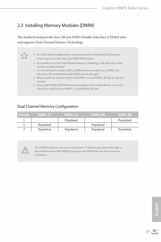
2.3 Installing Memory Modules (DIMM)
his motherboard provides four 240-pin DDR3 (Double Data Rate 3) DIMM slots,
and supports Dual Channel Memory Technology.
Dual Channel Memory Coniguration
he DIMM only its in one correct orientation. It will cause permanent damage to
the motherboard and the DIMM if you force the DIMM into the slot at incorrect
orientation.
Priority DDR3_A1 DDR3_A2 DDR3_B1 DDR3_B2
1 Populated Populated
2 Populated Populated
3 Populated Populated Populated Populated
1. For dual channel coniguration, you always need to install identical (the same
brand, speed, size and chip-type) DDR3 DIMM pairs.
2. It is unable to activate Dual Channel Memory Technology with only one or three
memory module installed.
3. It is not allowed to install a DDR or DDR2 memory module into a DDR3 slot;
otherwise, this motherboard and DIMM may be damaged.
4. Please install the memory module into DDR3_A2 and DDR3_B2 slots for the irst
priority.
5. If you adopt DDR3 2450/2100 memory modules on this motherboard, it is recom-
mended to install them on DDR3_A2 and DDR3_B2 slots.

18
English
1 2 3

Fatal1ty 990FX Killer Series
19
En
gli
sh
2.4 Expansion Slots (PCI Express Slots)
here are 5 PCI Express slots on the motherboard.
PCIe slots:
PCIE1 (PCIe 2.0 x1 slots) is used for PCI Express x1 lane width cards.
PCIE2 (PCIe 2.0 x16 slot) is used for PCI Express x16 lane width graphics cards.
PCIE3 (PCIe 2.0 x16 slot) is used for PCI Express x16 lane width graphics cards.
PCIE4 (PCIe 2.0 x1 slots) is used for PCI Express x1 lane width cards.
PCIE5 (PCIe 2.0 x16 slot) is used for PCI Express x4 lane width graphics cards
PCIe Slot Conigurations
PCIE2 PCIE3 PCIE5
Single Graphics Card x16 N/A N/A
Two Graphics Cards in
CrossFireXTM or SLITM Modex16 x16 N/A
hree Graphics Cards in
3-Way CrossFireXTM Modex16 x16 x4
For a better thermal environment, please connect a chassis fan to the motherboard’s
chassis fan connector (CHA_FAN1, CHA_FAN2 or CHA_FAN3) when using mul-
tiple graphics cards.
Before installing an expansion card, please make sure that the power supply is
switched of or the power cord is unplugged. Please read the documentation of the
expansion card and make necessary hardware settings for the card before you start
the installation.
20
En
glish
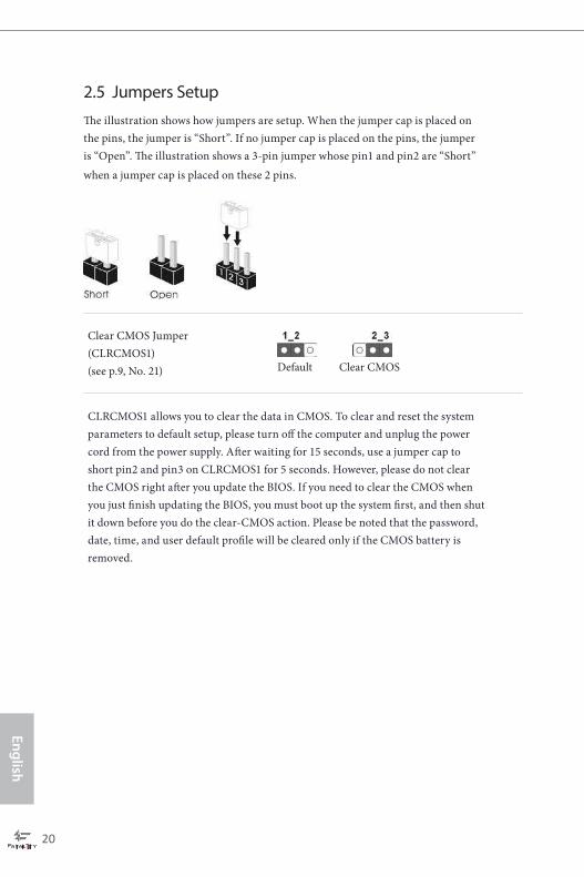
2.5 Jumpers Setup
he illustration shows how jumpers are setup. When the jumper cap is placed on
the pins, the jumper is “Short”. If no jumper cap is placed on the pins, the jumper
is “Open”. he illustration shows a 3-pin jumper whose pin1 and pin2 are “Short”
when a jumper cap is placed on these 2 pins.
Clear CMOS Jumper
(CLRCMOS1)
(see p.9, No. 21)
CLRCMOS1 allows you to clear the data in CMOS. To clear and reset the system
parameters to default setup, please turn of the computer and unplug the power
cord from the power supply. Ater waiting for 15 seconds, use a jumper cap to
short pin2 and pin3 on CLRCMOS1 for 5 seconds. However, please do not clear
the CMOS right ater you update the BIOS. If you need to clear the CMOS when
you just inish updating the BIOS, you must boot up the system irst, and then shut
it down before you do the clear-CMOS action. Please be noted that the password,
date, time, and user default proile will be cleared only if the CMOS battery is
removed.
Clear CMOSDefault

Fatal1ty 990FX Killer Series
21
En
gli
sh
2.6 Onboard Headers and Connectors
System Panel Header
(9-pin PANEL1)
(see p.9, No. 20)
Connect the power
switch, reset switch and
system status indicator on
the chassis to this header
according to the pin
assignments below. Note
the positive and negative
pins before connecting
the cables.
PWRBTN (Power Switch):
Connect to the power switch on the chassis front panel. You may conigure the way to
turn of your system using the power switch.
RESET (Reset Switch):
Connect to the reset switch on the chassis front panel. Press the reset switch to restart
the computer if the computer freezes and fails to perform a normal restart.
PLED (System Power LED):
Connect to the power status indicator on the chassis front panel. he LED is on when
the system is operating. he LED keeps blinking when the system is in S1/S3 sleep state.
he LED is of when the system is in S4 sleep state or powered of (S5).
HDLED (Hard Drive Activity LED):
Connect to the hard drive activity LED on the chassis front panel. he LED is on when
the hard drive is reading or writing data.
he front panel design may difer by chassis. A front panel module mainly consists
of power switch, reset switch, power LED, hard drive activity LED, speaker and etc.
When connecting your chassis front panel module to this header, make sure the wire
assignments and the pin assignments are matched correctly.
Onboard headers and connectors are NOT jumpers. Do NOT place jumper caps over
these headers and connectors. Placing jumper caps over the headers and connectors
will cause permanent damage to the motherboard.

22
En
glish
Power LED Header
(3-pin PLED1)
(see p.9, No. 18)
Please connect the chassis
power LED to this header
to indicate the system’s
power status.
Serial ATA3 Connectors
(SATA3_1:
see p.9, No. 17)
(SATA3_2:
see p.9, No. 16)
(SATA3_3:
see p.9, No. 14)
(SATA3_4:
see p.9, No. 15)
(SATA3_5:
see p.9, No. 12)
hese ive SATA3
connectors support SATA
data cables for internal
storage devices with up to
6.0 Gb/s data transfer rate.
USB 2.0 Headers
(9-pin USB6_7)
(see p.9, No. 9)
(9-pin USB8_9)
(see p.9, No. 8)
Besides six USB 2.0 ports
on the I/O panel, there
are two headers on this
motherboard. Each USB
2.0 header can support
two ports.
USB 3.0 Headers
(19-pin USB3_5_6)
(see p.9, No. 10)
(USB3_7)
(see p.9, No. 11)
Besides four USB 3.0 ports
on the I/O panel, there is
one header and one port
on this motherboard.
Each USB 3.0 header can
support two ports.
1
PLED+PLED+
PLED-
DUMMYGND
GND
P+P-
USB_PWR
P+P-
USB_PWR
1
SATA3_5
SATA3_1
SATA3_3
SATA3_2
SATA3_4
1
IntA_PB_D+
Dummy
IntA_PB_D-
GND
IntA_PB_SSTX+
GND
IntA_PB_SSTX-
IntA_PB_SSRX+
IntA_PB_SSRX-
VbusVbus
Vbus
IntA_PA_SSRX-
IntA_PA_SSRX+
GND
IntA_PA_SSTX-
IntA_PA_SSTX+
GND
IntA_PA_D-
IntA_PA_D+

Fatal1ty 990FX Killer Series
23
En
gli
sh
Front Panel Audio Header
(9-pin HD_AUDIO1)
(see p.9, No. 27)
his header is for
connecting audio devices
to the front audio panel.
Chassis Speaker Header
(4-pin SPEAKER1)
(see p.9, No. 19)
Please connect the chassis
speaker to this header.
Chassis and Power Fan
Connectors
(4-pin CHA_FAN1)
(see p.9, No. 29)
(3-pin CHA_FAN2)
(see p.9, No. 1)
(3-pin CHA_FAN3)
(see p.9, No. 22)
(3-pin PWR_FAN1)
(see p.9, No. 28)
Please connect fan cables
to the fan connectors and
match the black wire to
the ground pin.
J _ S E N S E
O U T 2 _ L
1
MIC_RETPRESENCE#
GND
OUT2_RMIC2_R
MIC2_L
OUT_RET
1. High Deinition Audio supports Jack Sensing, but the panel wire on the chassis must
support HDA to function correctly. Please follow the instructions in our manual and
chassis manual to install your system.
2. If you use an AC’97 audio panel, please install it to the front panel audio header by
the steps below:
A. Connect Mic_IN (MIC) to MIC2_L.
B. Connect Audio_R (RIN) to OUT2_R and Audio_L (LIN) to OUT2_L.
C. Connect Ground (GND) to Ground (GND).
D. MIC_RET and OUT_RET are for the HD audio panel only. You don’t need to
connect them for the AC’97 audio panel.
E. To activate the front mic, go to the “FrontMic” Tab in the Realtek Control panel
and adjust “Recording Volume”.
1
+5V
DUMMY
DUMMY
SPEAKER
GND+12V
FAN_SPEED
FAN_SPEED
FAN_SPEED_CONTROL
+12V
GND
GND+12V
FAN_SPEED
GND
+ 12V
FAN_SPEED

24
En
glish
CPU Fan Connectors
(4-pin CPU_FAN1)
(see p.9, No. 3)
(3-pin CPU_FAN2)
(see p.9, No. 4)
his motherboard pro-
vides a 4-Pin CPU fan
(Quiet Fan) connector.
If you plan to connect a
3-Pin CPU fan, please
connect it to Pin 1-3.
ATX Power Connector
(24-pin ATXPWR1)
(see p.9, No. 7)
his motherboard pro-
vides a 24-pin ATX power
connector. To use a 20-pin
ATX power supply, please
plug it along Pin 1 and Pin
13.
ATX 12V Power
Connector
(8-pin ATX12V1)
(see p.9, No. 2)
his motherboard pro-
vides an 8-pin ATX 12V
power connector. To use a
4-pin ATX power supply,
please plug it along Pin 1
and Pin 5.
SLI/XFIRE Power
Connector
(4-pin SLI/XFIRE_
PWR1)
(see p.9, No. 23)
Please connect this
connector with a hard
disk power connector
when three graphics
cards are installed on this
motherboard.
Infrared Module Header
(5-pin IR1)
(see p.9, No. 24)
his header supports an optional
wireless transmitting and
receiving infrared module.
12
1
24
13
GNDIRRX
DUMMY+5VSB
IRTX
1
4 1
8 5
GND+12V
CPU_FAN_SPEED
GND+12V
CPU_FAN_SPEED
FAN_SPEED_CONTROL
1 2 3 4

Fatal1ty 990FX Killer Series
25
En
gli
sh
Serial Port Header
(9-pin COM1)
(see p.9, No. 25)
his COM1 header
supports a serial port
module.
SPDIF Out Connector
(2-pin SPDIF_OUT1)
(see p.9, No. 26)
Please connect the
SPDIF_OUT connector of
a HDMI VGA card to this
header with a cable.
TPM Header
(17-pin TPMS1)
(see p.9, No. 13)
his connector supports
Trusted Platform Module
(TPM) system, which can
securely store keys, digital
certiicates, passwords,
and data. A TPM system
also helps enhance
network security, protects
digital identities, and
ensures platform integrity.
SPDIFOUT
GND
1
1
LFRAME#_L
CK_33M_TPM
TPM_RST#
LAD3_L
+3V
LAD0_L
+3VSB
GNDF_CLKRUN#
SERIRQ#
S_PWRDWN#
GND
LAD1_L
LAD2_L
SMB_DATA_MAIN
SMB_CLK_MAIN
GND

26
En
glish
2.7 SLITM
and Quad SLITM
Operation Guide
his motherboard supports NVIDIA® SLITM and Quad SLITM (Scalable Link
Interface) technology that allows you to install up to two identical PCI Express x16
graphics cards. Currently, NVIDIA® SLITM and Quad SLITM technology supports
Windows® 7 / 7 64-bit / 8 / 8 64-bit OS.
2.7.1 Installing Two SLITM
-Ready Graphics Cards
Step 1
Insert one graphics card into PCIE2 slot
and the other graphics card to PCIE3 slot.
Make sure that the cards are properly
seated on the slots.
Step 2
If required, connect the auxiliary power
source to the PCI Express graphics cards.
Requirements
1. You should only use identical SLITM-ready graphics cards that are NVIDIA® certi-
ied.
2. Make sure that your graphics card driver supports NVIDIA® SLITM technology.
Download the drivers from the NVIDIA® website: www.nvidia.com
3. Make sure that your power supply unit (PSU) can provide at least the minimum
power your system requires. It is recommended to use a NVIDIA® certiied PSU.
Please refer to the NVIDIA® website for details.
Fatal1ty 990FX Killer Series
27
En
gli
sh
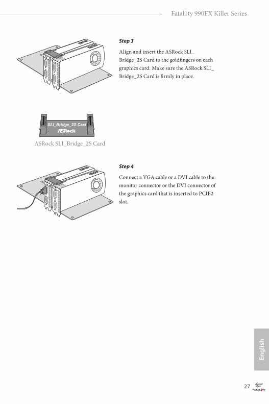
Step 3
Align and insert the ASRock SLI_
Bridge_2S Card to the goldingers on each
graphics card. Make sure the ASRock SLI_
Bridge_2S Card is irmly in place.
Step 4
Connect a VGA cable or a DVI cable to the
monitor connector or the DVI connector of
the graphics card that is inserted to PCIE2
slot.
ASRock SLI_Bridge_2S Card
SLI_Bridge_2S Card

28
En
glish
2.7.2 Driver Installation and Setup
Install the graphics card drivers to your system. Ater that, you can enable the
Multi-Graphics Processing Unit (GPU) in the NVIDIA® nView system tray utility.
Please follow the below procedures to enable the multi-GPU.
For SLITM
and Quad SLITM
mode
Step 1
Double-click the NVIDIA Control Panel
icon in the Windows® system tray.
Step 2
In the let pane, click Set SLI and PhysX
coniguration. hen select Maximize 3D
performance and click Apply.
Step 3
Reboot your system.
Step 4
You can freely enjoy the beneits of SLITM
or Quad SLITM.

Fatal1ty 990FX Killer Series
29
En
gli
sh
2.8 CrossFireXTM
, 3-Way CrossFireXTM
and Quad CrossFireXTM
Operation Guide
his motherboard supports CrossFireXTM, 3-way CrossFireXTM and Quad
CrossFireXTM that allows you to install up to three identical PCI Express
x16 graphics cards. Currently CrossFireXTM, 3-way CrossFireXTM and Quad
CrossFireXTM are supported with Windows® 7 / 7 64-bit / 8 / 8 64-bit OS.
2.8.1 Installing Two CrossFireXTM
-Ready Graphics Cards
Step 1
Insert one graphics card into PCIE2 slot
and the other graphics card to PCIE3 slot.
Make sure that the cards are properly
seated on the slots.
Step 2
Connect two graphics cards by installing
a CrossFire Bridge on the CrossFire Bridge
Interconnects on the top of the graphics
cards. (he CrossFire Bridge is provided
with the graphics card you purchase, not
bundled with this motherboard. Please
refer to your graphics card vendor for
details.)
1. You should only use identical CrossFireXTM-ready graphics cards that are AMD
certiied.
2. Make sure that your graphics card driver supports AMD CrossFireXTM technology.
Download the drivers from the AMD’s website: www.amd.com
3. Make sure that your power supply unit (PSU) can provide at least the minimum
power your system requires. It is recommended to use a AMD certiied PSU. Please
refer to the AMD’s website for details.
4. If you pair a 12-pipe CrossFireXTM Edition card with a 16-pipe card, both cards will
operate as 12-pipe cards while in CrossFireXTM mode.
5. Diferent CrossFireXTM cards may require diferent methods to enable CrossFi-
reXTM. Please refer to AMD graphics card manuals for detailed installation guide.
CrossFire Bridge

30
En
glish
2.8.2 Installing Three CrossFireXTM
-Ready Graphics Cards
Step 3
Connect a VGA cable or a DVI cable to the
monitor connector or the DVI connec-
tor of the graphics card that is inserted to
PCIE2 slot.
Step 1
Insert one graphics card into PCIE2 slot,
another graphics card to PCIE3 slot, and
the other graphics card to PCIE5 slot.
Make sure that the cards are properly
seated on the slots.
Step 2
Use one CrossFire Bridge to connect
the graphics cards on PCIE2 and PCIE3
slots, and use the other CrossFire Bridge
to connect the graphics cards on PCIE3
and PCIE5 slots. (he CrossFire Bridge
is provided with the graphics card
you purchase, not bundled with this
motherboard. Please refer to your graphics
card vendor for details.)
Step 3
Connect a VGA cable or a DVI cable to the
monitor connector or the DVI connec-
tor of the graphics card that is inserted to
PCIE2 slot.
CrossFire Bridge

Fatal1ty 990FX Killer Series
31
En
gli
sh
Step 1
Power on your computer and boot into OS.
Step 2
Remove the AMD drivers if you have any VGA drivers installed in your system.
Step 3
Install the required drivers and CATALYST Control Center then restart your
computer. Please check AMD’s website for details.
2.8.3 Driver Installation and Setup
Step 4
Double-click the AMD Catalyst Control
Center icon in the Windows® system tray.
Step 5
In the let pane, click Performance and
then AMD CrossFireXTM. hen select
Enable AMD CrossFireX and click Apply.
Select the GPU number according to your
graphics card and click Apply.
AMD Catalyst Control Center
he Catalyst Uninstaller is an optional download. We recommend using this utility to
uninstall any previously installed Catalyst drivers prior to installation. Please check
AMD’s website for AMD driver updates.

32
En
glish
2.9 M.2_SSD (NGFF) Module Installation Guide
The M.2, also known as the Next Generation Form Factor (NGFF), is a small size and
versatile card edge connector that aims to replace mPCIe and mSATA. The M.2_SSD
(NGFF) Socket 3 can accommodate either a M.2 SATA3 6.0 Gb/s module or a M.2 PCI
Express module up to Gen 2 x2 (10 Gb/s). Please be noted that the M.2_SSD (NGFF) Socket
3 is shared with the eSATA3 connector; you can only choose either the M.2_SSD (NGFF)
Socket 3 or the eSATA3 connector to use.
Installing the M.2_SSD (NGFF) Module
Step 1
Prepare a M.2_SSD (NGFF) module.
Step 2
Uninstall the screw knob and the
standoff counterclockwise for later
use.
Step 3
Depending on the PCB length of
your M.2_SSD (NGFF) module, ind
the corresponding NUT location to
be used.
No. 1 2 3 4
Location NUT1 NUT2 NUT3 NUT4
PCB Length 4.2cm 6cm 8cm 11cm
Module Type Type 2242 Type2260 Type 2280 Type 22110

Fatal1ty 990FX Killer Series
33
En
gli
sh
Step 4
Hand tighten the standoff into the
desired NUT on the motherboard.
Step 5
A lign and gent ly inser t t he M.2
(NGFF) SSD module into the M.2
slot. Please be aware that the M.2
(NGFF) SSD module only its in one
orientation.
Step 6
Tighten the screw knob to secure the
module into place.
M.2_SSD (NGFF) Module Support List
For the latest updates of M.2_SSD (NFGG) module support list, please visit our website for
details: http://www.asrock.com
PCIe Interface SATA Interface
SanDisk SD6PP4M-128G Intel SSDSCKGW080A401/80G
SanDisk SD6PP4M-256G

34
En
glish
Chapter 3 Software and Utilities Operation
3.1 Installing Drivers
he Support CD that comes with the motherboard contains necessary drivers and
useful utilities that enhance the motherboard’s features.
Running The Support CD
To begin using the support CD, insert the CD into your CD-ROM drive. he CD
automatically displays the Main Menu if “AUTORUN” is enabled in your computer.
If the Main Menu does not appear automatically, locate and double click on the ile
“ASRSETUP.EXE” in the Support CD to display the menu.
Drivers Menu
he drivers compatible to your system will be auto-detected and listed on the
support CD driver page. Please click Install All or follow the order from top to
bottom to install those required drivers. herefore, the drivers you install can work
properly.
Utilities Menu
he Utilities Menu shows the application sotware that the motherboard supports.
Click on a speciic item then follow the installation wizard to install it.

Fatal1ty 990FX Killer Series
35
En
gli
sh
3.2 F-Stream
F-Stream is an all-in-one tool to ine-tune diferent system functions in a user-
friendly interface, it includes Hardware Monitor, Fan Control, Overclocking,
Fatal1ty Mouse Port, Energy Saving and XFast RAM. In Hardware Monitor, it
shows the major readings of your system. In Fan Control, it shows the fan speed and
temperature for you to adjust. In Overclocking, you are allowed to overclock CPU
frequency for optimal system performance. In Fatal1ty Mouse Port, you can adjust
the mouse polling rate to enjoy Fatal1ty Mouse Polling feature. In Energy Saving,
you can enjoy the intelligent power saving feature. In XFast RAM, it fully utilizes
the memory space that cannot be used under Windows® OS 32-bit CPU. It also
shortens the loading time of previously visited websites, making web suring faster
than ever. And it also boosts the speed of Adobe Photoshop 5 times faster. Another
advantage is that it reduces the frequency of accessing your SSDs or HDDs in order
to extend their lifespan.
3.2.1 Installing F-Stream
When you install the all-in-one driver to your system from our support CD,
F-Stream will be auto-installed as well. Ater installation, you will ind the icon
“F-Stream“ on your desktop. Double-click the “F-Stream“ icon , and
the F-Stream main menu will pop out.
3.2.2 Using F-Stream
Please be noted that there is a button “Auto run when windows start“ on the lower
right corner. If you click this button, every time you turn on your system and enter
Windows®, the system will automatically start F-Stream.
here are six sections in the F-Stream main menu: Hardware Monitor, Fan Control,
Overclocking, Fatal1ty Mouse Port, Energy Saving and XFast RAM.

36
En
glish
Hardware Monitor
In the Hardware Monitor section, it shows the major readings of your system. he
main readings include Clock, Fan & Temperature, and Voltage. In Clock, there are
CPU speed and CPU ratio. In Fan & Temperature, there are CPU temperature and
CPU fan speed. You may ind out if there are any abnormal situations occuring to
your system’s temperature. In Voltage, there are many respective voltages.
Fan Control
In the Fan Control section, there are two major chapters: Temperature and CPU/
Chassis Fan. In Temperature, it shows the major readings of CPU and motherboard
temperature. In CPU/Chassis Fan, it shows the fan target speed and temperature,
and you are able to adjust the settings by clicking the “+/-” and conirming by
“APPLY” aterwards.
Fatal1ty 990FX Killer Series
37
En
gli
sh
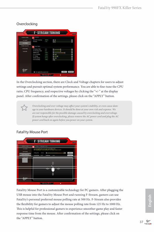
Overclocking
In the Overclocking section, there are Clock and Voltage chapters for users to adjust
settings and pursuit optimal system performance. You are able to ine-tune the CPU
ratio, CPU frequency, and respective voltages by clicking the “+/-” at the display
panel. Ater conirmation of the settings, please click on the “APPLY” button.
Fatal1ty Mouse Port
Fatal1ty Mouse Port is a customizable technology for PC gamers. Ater plugging the
USB mouse into the Fatal1ty Mouse Port and running F-Stream, gamers can use
Fatal1ty’s personal preferred mouse polling rate at 500 Hz. F-Stream also provides
the lexibility for gamers to adjust the mouse polling rate from 125 Hz to 1000 Hz.
his is helpful for professional gamers to experience smoother game play and faster
response time from the mouse. Ater conirmation of the settings, please click on
the “APPLY” button.
Overclocking and over-voltage may afect your system’s stability, or even cause dam-
age to your hardware devices. It should be done at your own risk and expense. We
are not responsible for the possible damage caused by overclocking and overvoltage.
If system hangs ater overclocking, please remove the AC power cord and plug the AC
power cord back on again before you power on your system.

38
En
glish
Energy Saving
Featuring an advanced proprietary hardware and sotware design, Energy Saving
is a revolutionary technology that delivers unparalleled power saving. he voltage
regulator can reduce the number of output phases to improve eiciency when the
CPU cores are idle. In other words, it is able to provide exceptional power saving
and improve power eiciency without sacriicing computing performance.
XFast RAM
XFast RAM fully utilizes the memory space that cannot be used under Windows®
OS 32-bit CPU. It also shortens the loading time of previously visited websites,
making web suring faster than ever. And it also boosts the speed of Adobe
Photoshop 5 times faster. Another advantage is that it reduces the frequency of
accessing your SSDs or HDDs in order to extend their lifespan.

Fatal1ty 990FX Killer Series
39
En
gli
sh
3.3 Killer Network Manager
Qualcomm® Atheros® Killer Network Manager allows you to control the upload and
download speeds for online applications accessing your network resources, as well as
allowing you to customize priority and bandwidth for all network traic to it your needs.
3.3.1 Installing Killer Network Manager
When you install the all-in-one driver to your system from ASRock’s support CD,
Killer Network Manager will be auto-installed as well. Ater the installation, you will
ind the icon “Killer Network Manager“ on your desktop. Double-click the icon,
Killer Network Manager main menu will pop up.
3.3.2 Using Killer Network Manager
here are four tabs in Killer Network Manager: Applications, Performance, Network
and Killer Ethernet.
Applications
Applications allows you to set the prioritization of network traic, increase or reduce
the bandwidth that a certain application uses, or block an application entirely.

40
En
glish
Performance
Performance allows you to view in real time your system performance and current
network utilization for download and upload traic.
Network
Network allows you to set your preferred upload/download speeds and test the
network speed.
* You must have Adobe Flash Player installed to run the network speed test.

Fatal1ty 990FX Killer Series
41
En
gli
sh
Killer Ethernet
Killer Ethernet displays the network information.

42
En
glish
3.4 Start8
For those Windows 8 users who miss the Start Menu, Start8 is an ideal solution that
brings back the familiar Start Menu along with added customizations for greater
eiciency.
3.4.1 Installing Start8
Install Start8, which is located in the folder at the following path of the Support CD:
\ ASRock Utility > Start8.
3.4.2 Coniguring Start8
Style
Select between the Windows 7 style and Windows 8 style Start Menu. hen select
the theme of the Start Menu and customize the style of the Start icon.

Fatal1ty 990FX Killer Series
43
En
gli
sh
Conigure
Conigure provides coniguration options, including icon sizes, which shortcuts you
want Start Menu to display, quick access to recently used apps, the functionality of
the power button, and more.
Control
44
En
glish
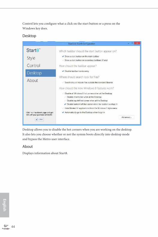
Control lets you conigure what a click on the start button or a press on the
Windows key does.
Desktop
Desktop allows you to disable the hot corners when you are working on the desktop.
It also lets you choose whether or not the system boots directly into desktop mode
and bypass the Metro user interface.
About
Displays information about Start8.

Fatal1ty 990FX Killer Series
45
En
gli
sh
3.5 XSplit Broadcaster
XSplit Broadcaster is a desktop application designed to make your multimedia
broadcasting, live-streaming and recording a lot easier and more fun to do, we are
giving away the 3 months premium license which is worth US$24.95 for free!
3.5.1 Live Streaming Your Gameplay
Step 1
Go to Start > All Programs > XSplit > XSplit Broadcaster to launch it.
Step 2
Log in with your own username and password. (If you do not have an XSplit
account, click No XSplit account? to register.)

46
En
glish
Step 3
Go to Broadcast > Add Channels….
Step 4
Click Add....
Step 5
Select a platform for live streaming.
*Before you start streaming, you need to register an account for the streaming
service website, such as Twitch.tv, USTREAM, or other livestreaming services.

Fatal1ty 990FX Killer Series
47
En
gli
sh
Step 6
Fill in your platform's Username and Password.
Based on your needs, conigure the Video and Audio Encoding settings. Click OK.
Step 7
he channel then appears in your broadcast list. Click Apply and OK to save the
settings.

48
En
glish
Step 8
Go to Broadcast and select the platform to enable live streaming.
A link to view your live Broadcast has been copied for you automatically. Simply
press CTRL-V or right click and choose Paste to paste the link into the browser, and
you can see your broadcast.
To disable live streaming, go to Broadcast again and deselect the platform.
3.5.2 Recording Your Gameplay
Step 1
Go to Broadcast > Local recording to start recording.
Step 2
To stop recording, Go to Broadcast again and deselect Local recording.
Step 3
Go to Tools > My Recordings...to access your recordings

Fatal1ty 990FX Killer Series
49
En
gli
sh
Chapter 4 UEFI SETUP UTILITY
4.1 Introduction
his section explains how to use the UEFI SETUP UTILITY to conigure your
system. You may run the UEFI SETUP UTILITY by pressing <F2> or <Del> right
ater you power on the computer, otherwise, the Power-On-Self-Test (POST) will
continue with its test routines. If you wish to enter the UEFI SETUP UTILITY ater
POST, restart the system by pressing <Ctl> + <Alt> + <Delete>, or by pressing the
reset button on the system chassis. You may also restart by turning the system of
and then back on.
4.1.1 UEFI Menu Bar
he top of the screen has a menu bar with the following selections:
Main For setting system time/date information
OC Tweaker For overclocking conigurations
Advanced For advanced system conigurations
Tool Useful tools
H/W Monitor Displays current hardware status
Boot For coniguring boot settings and boot priority
Security For security settings
Exit Exit the current screen or the UEFI Setup Utility
Because the UEFI sotware is constantly being updated, the following UEFI setup
screens and descriptions are for reference purpose only, and they may not exactly
match what you see on your screen.

50
En
glish
4.1.2 Navigation Keys
Use < > key or < > key to choose among the selections on the menu bar, and
use < > key or < > key to move the cursor up or down to select items, then
press <Enter> to get into the sub screen. You can also use the mouse to click your
required item.
Please check the following table for the descriptions of each navigation key.
Navigation Key(s) Description
+ / - To change option for the selected items
<Tab> Switch to next function
<PGUP> Go to the previous page
<PGDN> Go to the next page
<HOME> Go to the top of the screen
<END> Go to the bottom of the screen
<F1> To display the General Help Screen
<F7> Discard changes and exit the SETUP UTILITY
<F9> Load optimal default values for all the settings
<F10> Save changes and exit the SETUP UTILITY
<F12> Print screen
<ESC> Jump to the Exit Screen or exit the current screen

Fatal1ty 990FX Killer Series
51
En
gli
sh
4.2 Main Screen
When you enter the UEFI SETUP UTILITY, the Main screen will appear and
display the system overview.
Active Page on Entry
Select the default page when entering the UEFI setup utility.

52
En
glish
Because the UEFI sotware is constantly being updated, the following UEFI setup
screens and descriptions are for reference purpose only, and they may not exactly
match what you see on your screen.
4.3 OC Tweaker Screen
In the OC Tweaker screen, you can set up overclocking features.
OC Mode
Use this to select Overclock Mode. Please note that overclocing may cause damage
to your components and motherboard. It should be done at your own risk and
expense.
Load Optimized CPU OC Setting
Please note that overclocking may cause damage to your CPU and motherboard. It
should be done at your own risk and expense.
CPU Coniguration
Overclock Mode
Use this to select Overclock Mode. Coniguration options: [Auto] and [Manual]. he
default value is [Auto].

Fatal1ty 990FX Killer Series
53
En
gli
sh
Spread Spectrum
his item should always be [Auto] for better system stability.
ASRock UCC
ASRock UCC (Unlock CPU Core) feature simpliies AMD CPU activation. As long as
a simple switch of the UEFI option “ASRock UCC”, you can unlock the extra CPU core
to enjoy an instant performance boost. When UCC feature is enabled, the dual-core
or triple-core CPU will boost to the quad-core CPU, and some CPU, including quad-
core CPU, can also increase L3 cache size up to 6MB, which means you can enjoy the
upgrade CPU performance with a better price. Please be noted that UCC feature is
supported with AM3/AM3+ CPU only, and in addition, not every AM3/AM3+ CPU
can support this function because some CPU’s hidden core may be malfunctioned.
CPU Active Core Control
his allows you to adjust CPU Active Core Control feature. he coniguration options
depend on the CPU core you adopt. he default value is [Disabled].
AMD Turbo Core Technology
his item appears only when the processor you adopt supports this feature. Use this
to select enable or disable AMD Turbo Core Technology. Coniguration options:
[Enabled] and [Disabled]. he default value is [Enabled].
AMD Application Power Management
Application Power Management (APM) ensures that average power con-sumption
over a thermally signiicant time period remains at or below the TDP for the CPU
mode being used. If [Enabled] is selected, the power consumption is reduced when
overclocking.
Processor Maximum Frequency
It will display Processor Maximum Frequency for reference.
North Bridge Maximum Frequency
It will display North Bridge Maximum Frequency for reference.
Processor Maximum Voltage
It will display Processor Maximum Voltage for reference.
Multiplier/Voltage Change
his item is set to [Auto] by default. If it is set to [Manual], you may adjust the value of
Processor Frequency and Processor Voltage. However, it is recommended to keep the
default value for system stability.

54
En
glish
CPU Frequency Multiplier
For safety and system stability, it is not recommended to adjust the value of this item.
CPU Voltage
It allows you to adjust the value of CPU voltage. However, for safety and system
stability, it is not recommended to adjust the value of this item.
NB Frequency Multiplier
For safety and system stability, it is not recommended to adjust the value of this item.
CPU NB Voltage
It allows you to adjust the value of CPU NB voltage. However, for safety and system
stability, it is not recommended to adjust the value of this item.
HT Bus Speed
his feature allows you selecting Hyper-Transport bus speed. Coniguration options:
[200MHz] to [2000MHz].
HT Bus Width
his feature allows you selecting Hyper-Transport bus width. Coniguration options: [8
Bit] and [16 Bit].
DRAM Timing Coniguration
DRAM Frequency
If [Auto] is selected, the motherboard will detect the memory module(s) inserted
and assign the appropriate frequency automatically.

Fatal1ty 990FX Killer Series
55
En
gli
sh
DRAM Timing Control
DRAM Slot
Use this item to view SPD data.
DRAM Timing Control
Use this item to control DRAM timing.
Power Down Enable
Use this item to enable or disable DDR power down mode.
Bank Interleaving
Interleaving allows memory accesses to be spread out over banks on the same node, or
accross nodes, decreasing access contention.
Channel Interleaving
It allows you to enable Channel Memory Interleaving. Coniguration options:
[Disabled], [Auto]. he default value is [Auto].
Voltage Coniguration
DRAM Voltage
Use this to select DRAM Voltage. he default value is [Auto].

56
En
glish
CPU Voltage Ofset
Conigure the dynamic CPU voltage added to the CPU.
NB Voltage
Use this to select NB Voltage. he default value is [Auto].
HT Voltage
Use this to select HT Voltage. he default value is [Auto].
CPU VDDA Voltage
Use this to select CPU VDDA Voltage. he default value is [Auto].
PCIE VDDA Voltage
Use this to select PCIE VDDA Voltage. he default value is [Auto].

Fatal1ty 990FX Killer Series
57
En
gli
sh
4.4 Advanced Screen
In this section, you may set the conigurations for the following items: CPU
Coniguration, North Bridge Coniguration, South Bridge Coniguration, Storage
Coniguration, Super IO Coniguration, ACPI Coniguration, USB Coniguration
and Trusted Computing.
Setting wrong values in this section may cause the system to malfunction.

58
En
glish
4.4.1 CPU Coniguration
Cool 'n' Quiet
Use this item to enable or disable AMD’s Cool ‘n’ QuietTM technology. he default
value is [Enabled]. Coniguration options: [Enabled] and [Disabled]. If you install
Windows® 8 / 7 / VistaTM and want to enable this function, please set this item to
[Enabled]. Please note that enabling this function may reduce CPU voltage and
memory frequency, and lead to system stability or compatibility issue with some
memory modules or power supplies. Please set this item to [Disable] if above issue
occurs.
Enhance Halt State (C1E)
All processors support the Halt State (C1). he C1 state is supported through the
native processor instructions HLT and MWAIT and requires no hardware support
from the chipset. In the C1 power state, the processor maintains the context of the
system caches.
Secure Virtual Machine
When this option is set to [Enabled], a VMM (Virtual Machine Architecture) can
utilize the additional hardware capabilities provided by AMD-V. he default value is
[Enabled]. Coniguration options: [Enabled] and [Disabled].
Core C6 Mode
Use this item to enable or disable Core C6 mode. he default value is [Enabled].

Fatal1ty 990FX Killer Series
59
En
gli
sh
CPU Thermal Throttle
Use this item to enable CPU internal thermal control mechanism to keep the CPU
from overheated. he default value is [Auto].

60
En
glish
4.4.2 North Bridge Coniguration
IOMMU
Use this to enable or disable IOMMU. he default value of this feature is [Disabled].

Fatal1ty 990FX Killer Series
61
En
gli
sh
4.4.3 South Bridge Coniguration
Onboard HD Audio
Enable/disable onboard HD audio. Set to Auto to enable onboard HD audio and
automatically disable it when a sound card is installed.
Front Panel
Enable/disable front panel HD audio.
Onboard LAN
Enable or disable the onboard network interface controller.
Good Night LED
By enabling Good Night LED, the Power/HDD LEDs will be switched of when the
system is on. It will also automatically switch of the Power and Keyboard LEDs
when the system enters into Standby/Hibernation mode.

62
En
glish
4.4.4 Storage Coniguration
SATA Controller(s)
Enable/disable the SATA controllers.
SATA Mode
IDE: For better compatibility.
AHCI: Supports new features that improve performance.
RAID: Combine multiple disk drives into a logical unit.
AMD AHCI BIOS ROM
Use this item to enable or disable AMD AHCI BIOS ROM. he default value of this
option is [Disabled].
SATA IDE Combined Mode
his item is for SATA3_5 and eSATA3 ports. Use this item to enable or disable
SATA IDE combined mode. he default value is [Enabled].
If you set this item to RAID mode, it is suggested to install SATA ODD driver on
SATA3_5 or eSATA3 port.

Fatal1ty 990FX Killer Series
63
En
gli
sh
Aggressive Link Power Management
Aggressive Link Power Management allows SATA devices to enter a low power state
during periods of inactivity to save power. It is only supported by AHCI mode.
Hard Disk S.M.A.R.T.
S.M.A.R.T stands for Self-Monitoring, Analysis, and Reporting Technology. It is a
monitoring system for computer hard disk drives to detect and report on various
indicators of reliability.
If you want to build RAID on SATA3_5 and eSATA3 ports, please disable this item.
64
En
glish
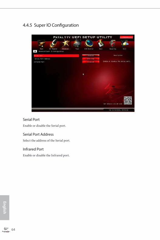
4.4.5 Super IO Coniguration
Serial Port
Enable or disable the Serial port.
Serial Port Address
Select the address of the Serial port.
Infrared Port
Enable or disable the Infrared port.

Fatal1ty 990FX Killer Series
65
En
gli
sh
4.4.6 ACPI Coniguration
Suspend to RAM
Select disable for ACPI suspend type S1. It is recommended to select auto for ACPI
S3 power saving.
Check Ready Bit
Enable to enter the operating system ater S3 only when the hard disk is ready, this
is recommended for better system stability.
ACPI HPET Table
Enable the High Precision Event Timer for better performance and to pass WHQL
tests.
Restore on AC/Power Loss
Select the power state ater a power failure. If [Power Of] is selected, the power will
remain of when the power recovers. If [Power On] is selected, the system will start
to boot up when the power recovers.
PS/2 Keyboard Power On
Allow the system to be waked up by a PS/2 Keyboard.
PCI Devices Power On
Allow the system to be waked up by a PCI device and enable wake on LAN.

66
En
glish
Ring-In Power On
Allow the system to be waked up by onboard COM port modem Ring-In signals.
RTC Alarm Power On
Allow the system to be waked up by the real time clock alarm. Set it to By OS to let
it be handled by your operating system.
USB Phy Power On
Allow the system to be waked up by an USB Phy.
USB Keyboard/Remote Power On
Allow the system to be waked up by an USB keyboard or remote controller.
USB Mouse Power On
Allow the system to be waked up by an USB mouse.
CSM
Enable to launch the Compatibility Support Module. Please do not disable unless
you’re running a WHCK test. If you are using Windows 8 64-bit and all of your
devices support UEFI, you may also disable CSM for faster boot speed.

Fatal1ty 990FX Killer Series
67
En
gli
sh
4.4.7 USB Coniguration
USB Controller
Enable or disable all the USB 2.0 ports.
USB 3.0 Controller
Enable or disable all the USB 3.0 ports.
Legacy USB Support
Enable or disable Legacy OS Support for USB 2.0 devices. If you encounter USB
compatibility issues it is recommended to disable legacy USB support. Select UEFI
Setup Only to support USB devices under the UEFI setup and Windows/Linux
operating systems only.
Legacy USB 3.0 Support
Enable or disable Legacy OS Support for USB 3.0 devices.

68
En
glish
4.4.8 Trusted Computing
Security Device Support
Enable to activate Trusted Platform Module (TPM) security for your hard disk
drives.

Fatal1ty 990FX Killer Series
69
En
gli
sh
4.5 Tools
System Browser
ASRock System Browser shows the overview of your current PC and the devices
connected.
OMG (Online Management Guard)
Administrators are able to establish an internet curfew or restrict internet access
at speciied times via OMG. You may schedule the starting and ending hours of
internet access granted to other users. In order to prevent users from bypassing
OMG, guest accounts without permission to modify the system time are required.
UEFI Tech Service
Contact ASRock Tech Service if you are having trouble with your PC. Please setup
network coniguration before using UEFI Tech Service.
Easy RAID Installer
Easy RAID Installer helps you to copy the RAID driver from the support CD to
your USB storage device. Ater copying the drivers please change the SATA mode to
RAID, then you can start installing the operating system in RAID mode.
Easy Driver Installer
For users that don’t have an optical disk drive to install the drivers from our support
CD, Easy Driver Installer is a handy tool in the UEFI that installs the LAN driver to
your system via an USB storage device, then downloads and installs the other

70
En
glish
required drivers automatically.
Instant Flash
Save UEFI iles in your USB storage device and run Instant Flash to update your
UEFI.
Internet Flash
ASRock Internet Flash downloads and updates the latest UEFI irmware version
from our servers for you. Please setup network coniguration before using Internet
Flash.
*For BIOS backup and recovery purpose, it is recommended to plug in your USB
pen drive before using this function.
Network Coniguration
Use this to conigure internet connection settings for Internet Flash.
Internet Setting
Enable or disable sound efects in the setup utility.
UEFI Download Server
Select a server to download the UEFI irmware.

Fatal1ty 990FX Killer Series
71
En
gli
sh
Dehumidiier Function
If Dehumidiier Function is enabled, the computer will power on automatically to
dehumidify the system ater entering S4/S5 state.
Dehumidiier Period
Conigure the period of time until the computer powers on and enables
Dehumidiier ater entering S4/S5 state.
Dehumidiier Duration
Conigure the duration of the dehumidifying process before it returns to S4/S5
state.
Dehumidiier CPU Fan Setting
Conigure the speed of the CPU fan while Dehumidiier is enabled. he higher the
value, the faster the fan speed.
Max: 255
Min: 1
Save User Default
Type a proile name and press enter to save your settings as user default.
Load User Default
Load previously saved user defaults.

72
En
glish
4.6 Hardware Health Event Monitoring Screen
his section allows you to monitor the status of the hardware on your system,
including the parameters of the CPU temperature, motherboard temperature, fan
speed and voltage.
CPU Fan 1 & 2 Setting
his allows you to set the CPU fan 1 & 2 speed. Coniguration options: [Full On]
and [Automatic Mode]. he default is value [Full On].
Chassis Fan 1 Setting
his allows you to set the chassis fan 1 speed. Coniguration options: [Full On] and
[Automatic Mode]. he default is value [Full On].
Chassis Fan 2 Setting
his allows you to set the chassis fan 2 speed. Coniguration options: [Full On] and
[Manual]. he default is value [Full On].
Chassis Fan 3 Setting
his allows you to set the chassis fan 3 speed. Coniguration options: [Full On] and
[Manual]. he default is value [Full On].

Fatal1ty 990FX Killer Series
73
En
gli
sh
4.7 Boot Screen
his section displays the available devices on your system for you to conigure the
boot settings and the boot priority.
Fast Boot
Fast Boot minimizes your computer's boot time. In fast mode you may not boot
from an USB storage device. Ultra Fast mode is only supported by Windows 8 and
the VBIOS must support UEFI GOP if you are using an external graphics card.
Please notice that Ultra Fast mode will boot so fast that the only way to enter this
UEFI Setup Utility is to Clear CMOS or run the Restart to UEFI utility in Windows.
Boot From Onboard LAN
Allow the system to be waked up by the onboard LAN.
Setup Prompt Timeout
Conigure the number of seconds to wait for the setup hot key.
Bootup Num-Lock
Select whether Num Lock should be turned on or of when the system boots up.
Full Screen Logo
Enable to display the boot logo or disable to show normal POST messages.
74
En
glish
AddOn ROM Display
Enable AddOn ROM Display to see the AddOn ROM messages or conigure the
AddOn ROM if you've enabled Full Screen Logo. Disable for faster boot speed.
Boot Failure Guard
If the computer fails to boot for a number of times the system automatically restores
the default settings.
Boot Failure Guard Count
Conigure the number of attempts to boot until the system automatically restores
the default settings.

Fatal1ty 990FX Killer Series
75
En
gli
sh
4.8 Security Screen
In this section you may set or change the supervisor/user password for the system.
You may also clear the user password.
Supervisor Password
Set or change the password for the administrator account. Only the administrator
has authority to change the settings in the UEFI Setup Utility. Leave it blank and
press enter to remove the password.
User Password
Set or change the password for the user account. Users are unable to change the
settings in the UEFI Setup Utility. Leave it blank and press enter to remove the
password.
Secure Boot
Enable to support Windows 8 Secure Boot.

76
En
glish
4.9 Exit Screen
Save Changes and Exit
When you select this option the following message, “Save coniguration changes
and exit setup?” will pop out. Select [OK] to save changes and exit the UEFI SETUP
UTILITY.
Discard Changes and Exit
When you select this option the following message, “Discard changes and exit
setup?” will pop out. Select [OK] to exit the UEFI SETUP UTILITY without saving
any changes.
Discard Changes
When you select this option the following message, “Discard changes?” will pop
out. Select [OK] to discard all changes.
Load UEFI Defaults
Load UEFI default values for all options. he F9 key can be used for this operation.

Fatal1ty 990FX Killer Series
77
En
gli
sh
Contact Information
If you need to contact ASRock or want to know more about ASRock, you’re welcome
to visit ASRock’s website at http://www.asrock.com; or you may contact your dealer
for further information. For technical questions, please submit a support request
form at http://www.asrock.com/support/tsd.asp
ASRock Incorporation
2F., No.37, Sec. 2, Jhongyang S. Rd., Beitou District,
Taipei City 112, Taiwan (R.O.C.)
ASRock EUROPE B.V.
Bijsterhuizen 3151
6604 LV Wijchen
he Netherlands
Phone: +31-24-345-44-33
Fax: +31-24-345-44-38
ASRock America, Inc.
13848 Magnolia Ave, Chino, CA91710
U.S.A.
Phone: +1-909-590-8308
Fax: +1-909-590-1026