Embed Size (px)
Citation preview

1
VERSION 05162016
Coast Spas Manufacturing Inc.
6315 202 Street, Langley BC Canada
604 514 8111
www.coastspas.com
2
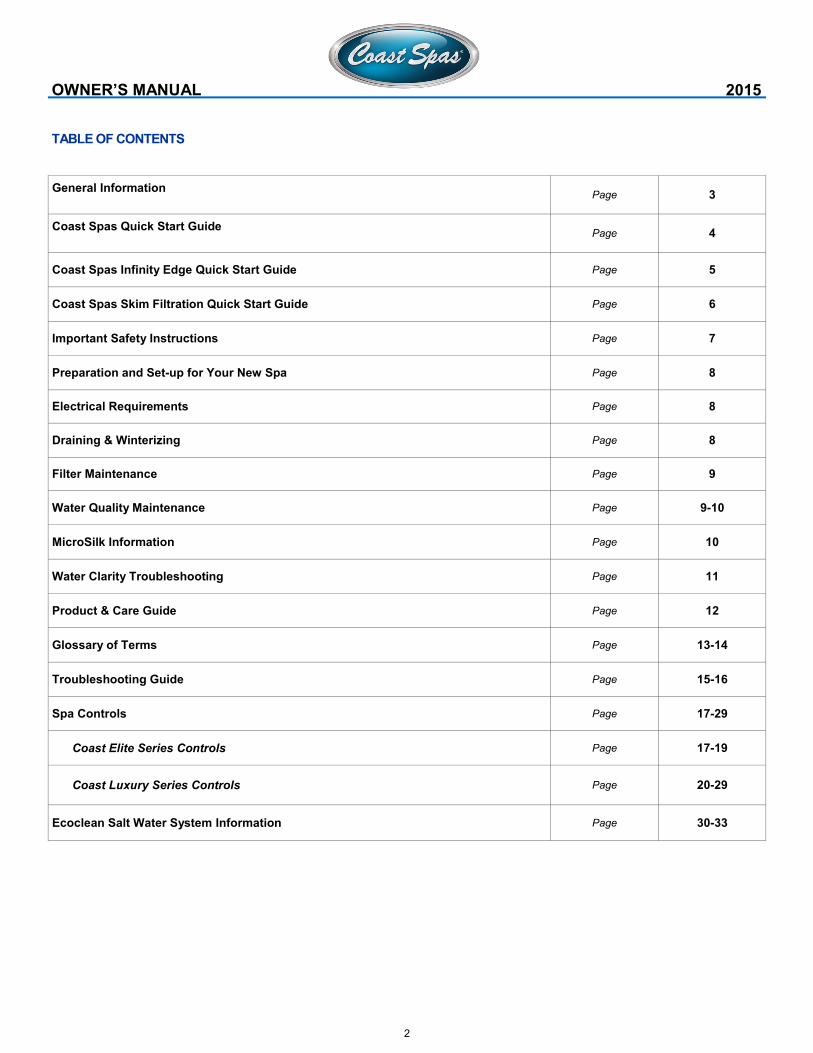
TABLE OF CONTENTS
OWNER’S MANUAL 2015
General Information
Page 3
Coast Spas Quick Start Guide
Page 4
Coast Spas Infinity Edge Quick Start Guide Page 5
Coast Spas Skim Filtration Quick Start Guide Page 6
Important Safety Instructions Page 7
Preparation and Set-up for Your New Spa Page 8
Electrical Requirements Page 8
Draining & Winterizing Page 8
Filter Maintenance Page 9
Water Quality Maintenance Page 9-10
MicroSilk Information Page 10
Water Clarity Troubleshooting Page 11
Product & Care Guide Page 12
Glossary of Terms Page 13-14
Troubleshooting Guide Page 15-16
Spa Controls Page 17-29
Coast Elite Series Controls Page 17-19
Coast Luxury Series Controls Page 20-29
Ecoclean Salt Water System Information Page 30-33
3
4
5
6
7
IMPORTANT SAFETY INSTRUCTIONS
READ AND FOLLOW ALL INSTRUCTIONS CAREFULLY
DANGER: Risk of Injury. The suction fittings in this hot tub are sized to
match the specific water flow created by the pump. Should the need
arise to replace the suction fittings or the pump, be sure that the flow
rates are compatible. Never operate the hot tub if the suction fittings are
broken or missing. Never replace a suction fitting with one rated less
than the flow rate marked on the original suction fitting.
DANGER: Risk of Accidental Drowning. Do not allow children to be in or
around the spa without adult supervision. Keep the spa cover on and
locked when not in use. See instructions enclosed with the cover for
locking procedures.
DANGER: Risk of Electrical Shock. The electrical supply for this product
must include a suitably rated switch or circuit breaker to open all un-
grounded supply conductors to comply with section 422-20 of the Na-
tional Electrical Code, ANSI/NFPA 70. The disconnect must be readily
accessible and visible to the hot tub occupant but installed at least 5 feet
(1.5 m) from the hot tub water.
READ, FOLLOW AND SAVE THESE INSTRUCTIONS
a) A green colored terminal or a terminal marked G, Gr, Ground,
Grounding or the symbol * is located inside the supply terminal box or
compartment. To reduce the risk of electric shock, this terminal must
be connected to the grounding means provided in the electric supply
service panel with a continuous copper wire equivalent in size to the
circuit conductors that supply this equipment.
b) At least two lugs marked “Bonding Lugs” are provided on the
external surface or on the inside of the supply terminal box
compartment. To reduce the risk of electric shock, connect the local
common bonding grid in the area of the hot tub to these terminals with
an insulated or bare copper conductor not smaller than No. 6 AWG.
c) All field-installed metal components such as rails, ladders, drains or
other similar hardware within 5 feet (1.5 m) of the hot tub shall be
bonded to the equipment grounding buss with copper conductors not
smaller than No. 6 AWG.
WARNING: To Reduce the Risk of Injury: The water in a hot tub should
never exceed 104 °F (40 °C). Water temperatures between 100 °F (38 °
C) and 104 °F (40 °C) are considered safe for a healthy adult. Lower
water temperatures are recommended for young children and when hot
tub use exceeds 10 minutes. Since excessive water temperatures have
a high potential for causing fetal damage during the early months of
pregnancy, pregnant or possibly pregnant women should limit hot tub
water temperatures to 100 °F (38 °C). If pregnant, please consult your
physician before using a hot tub. Before entering the hot tub, the user
should measure the water temperature with an accurate thermometer
since the tolerance of water temperature regulating devices may vary as
much as +/- 5 °F (2 °C). Persons suffering from obesity or a medical
history of heart disease, low or high blood pressure, circulatory system
problems or diabetes should consult a physician before using a hot tub.
CAUTION: Risk of Hyperthermia: Hyperthermia occurs when the internal
temperature of the body reaches a level several degrees above the
OWNER’S MANUAL 2015
normal body temperature of 98.6 °F (37 °C). The symptoms of hyperther-
mia include drowsiness, lethargy, and an increase in the internal tem-
perature of the body. Prolonged immersion in hot water may induce hy-
perthermia. A description of the causes, symptoms, and effects of hyper-
thermia are as follows:
Unawareness of impending hazard;
Failure to perceive heat;
Failure to recognize the need to exit hot tub;
Physical inability to exit hot tub;
Fetal damage in pregnant women; and
Unconsciousness and danger of drowning.
WARNING: Children should not use hot tubs without adult supervision.
WARNING: Do not use hot tubs unless all suction guards are installed to
prevent body and hair entrapment.
WARNING: People with infectious diseases should not use a hot tub.
WARNING: To avoid injury, exercise care when entering or exiting the
hot tub.
WARNING: Do not use drugs or alcohol before or during the use of a hot
tub to avoid unconsciousness and possible drowning. The use of alcohol
or drugs can greatly increase the risk of fatal hyperthermia in hot tubs.
WARNING: Pregnant or possibly pregnant women should consult a phy-
sician before using a hot tub.
WARNING: Water temperature in excess of 38 °C (100 °F) may be injuri-
ous to your health. Before entering the hot tub, measure the water tem-
perature with an accurate thermometer.
WARNING: Do not use a hot tub immediately following strenuous exer-
cise.
WARNING: Prolonged immersion in a hot tub may be injurious to your
health.
WARNING: Do not permit electric appliances (such as lights, telephone,
radio, television, etc.) within 5 feet (1.5m) of this hot tub unless such
appliances are built-in by the manufacturer.
WARNING: People using medication and/or having an adverse medical
history should consult a physician before using a spa or hot tub.
CAUTION: Observe a reasonable time limit when using the hot tub. Long
exposures at higher temperatures can cause high body temperature.
Symptoms may include dizziness, nausea, fainting, drowsiness, and
reduced awareness. These effects could possibly result in drowning.
CAUTION: Enter and exit the hot tub slowly. Wet surfaces can be very
slippery.
CAUTION: Proper chemical maintenance of hot tub water is necessary
to maintain safe water and prevent possible damage to hot tub compo-
nents. Maintain water chemistry in accordance with manufacturer’s in-
structions.
CAUTION: Use the straps and clip tie downs to secure the cover when
not in use. This will help to discourage unsupervised children from enter-
ing the hot tub and keep the hot tub cover secure in high-wind conditions.
There is no representation that the cover, clip tie-downs, or actual locks
will prevent access to the hot tub.
CAUTION: For exercise, the water should not exceed 90 °F (32 °C).
CAUTION: When using this electrical equipment, basic safety precau-
tions should always be followed.
8
PREPARATION AND SET-UP FOR YOUR NEW SPA
LOCATION FOR YOUR NEW SPA:
You want to keep in mind how you intend to use the spa and plan the location
accordingly.
How close is the spa from the exit or entrance to your house? (consider the
cold weather)
Is the path to your spa clean of debris, sand, grass? (so as not to track into the
spa)
Is there protection from wind, inclement weather?
Can neighbors or passersby see the spa?
NOTE: Allow for service access: Many spa owners enjoy placing their
spa in a decorative enclosure or a deck. Keep in mind that you need to
have access to the equipment for maintenance and the spa should be
able to be moved or lifted without destroying the special enclosure or its
surroundings. You should discuss this with your dealer when designing
the location. Extension cords are not to be used in conjunction with the
operations of the spa. Low voltage damage could result and this is not
covered by warranty. NOTE: All components must be 120V; No 240V
components allowable.
240VAC: Depending on the model of spa, it will require either a 40 Amp
or 50 Amp dedicated circuit breaker, GFCI, with the proper wire size
based on the length of the run. The electrical circuit must be installed by
a certified electrician and approved by a local building or electrical in-
spector.
ELECTRICAL REQUIREMENTS
All self contained spas use 120VAC or 240VAC electrical spa packs..
These instructions describe the only acceptable electrical wiring proce-
dures. Spas wired in any other way will void your warranty and may
result in serious injury. All installations should be completed by a certi-
fied electrician. Failure to comply with state and local codes may result
in fire or personal injury and will be the sole responsibility of the spa
owner.
120VAC: This requires an isolated 20 Amp circuit breaker. This needs to
be an isolated circuit with no other appliances or lights on this circuit at
any time. Extension cords are not to be used in conjunction with the
operations of the spa. Low voltage damage could result and this is not
covered by warranty. NOTE: All components must be 120V; No 240V
components allowable.
240VAC: Depending on the model of spa, it will require either a 40 Amp
or 50 Amp dedicated circuit breaker, GFCI, with the proper wire size
based on the length of the run. The electrical circuit must be installed by
a certified electrician and approved by a local building or electrical in-
spector.
OWNER’S MANUAL 2015
SURFACE AND PAD REQUIREMENTS
Your new portable spa must be placed on a firm, flat and level surface,
so the spa weight is supported uniformly. We recommend no less than a
3” (93 mm) thick concrete slab. Wood decking or balconies must be con-
structed to support 150 pounds per square foot (730 kg/m²). Refer to
local and current building codes in your area. Consult an engineer
for live loads in your area. Should your new spa need to go through a
gate, the opening should be a minimum of 48 inches and up to 8.5’ over-
head clearance depending on the size of the unit.
NOTE: Damage caused by alternate decking methods may avoid the spa
warranty. Contact your local dealer if you have any questions regarding
spa location or placement.
DRAINING AND WINTERIZING
DRAINING YOUR SPA
After a period of 3-4 months, detergent residues from bathing suits and
soap film will build up in your spa water. Once this happens, your spa
water will appear cloudy and should probably be replaced.
Turn power OFF at the breaker.
Locate the drain valve (usually in the equipment area).
Remove the safety cap and attach garden hose.
Drain water to a convenient area. (Spa water may harm grass or plants if sani-
tizer levels are high.)
When water begins to flow out of the hose, open the air relief valve located on
filter lid (Hydro-Cyclonic Filtration) or Air Bleeder Valve (Skim Filtration)
Your spa will drain except for a small portion left in the foot well. This can be
removed with a sponge and pail.
Once empty, clean as required.
To finish, remove garden hose and attach safety cap.
IMPORTANT (Cascade Series Only): There will be an additional drain
valve. This is connected directly to the tank reservoir and you will see the
water level go down on the sight tube in the equipment area.
WINTERIZING YOUR SPA
In many areas of the world the temperature may drop below 32°F
(0°C). We recommend the spa is always filled with water and running at
normal spa temperatures. By doing this you will minimize the risk of
freezing within your spa. If it is necessary to leave your spa unattended
for long periods of time during cold weather conditions, you should drain
your spa to avoid accidental freezing caused by power outages.
Your local dealer can perform the following winterizing procedures, if you
are not completely comfortable with them.
Ensure that you have fully drained the spa (Refer to the DRAINING YOUR SPA
section)
After draining, your spa may still have water remaining in the equipment and
plumbing fittings. Disconnect the hand-tightened union fittings going to and from
the jet pumps. Be careful not to lose the o-rings between the unions and pump
housing.
Leave drain valve in the open position and safety cap off .
To completely drain the plumbing lines, a wet/dry shop vacuum can be used to
draw out any remaining water. Place the vacuum hose over the jet fittings in the
9
spa as well as the plumbing lines in the equipment area. You should also dis-
connect the plug on the crystal clear inspection tube (if installed)
Remove the filter cartridge and store in a warm, dry area.
Clean the spa shell and place spa cover on spa. Be sure to lock the cover in
place in case of high winds or rain.
WARNING: The instructions above should be followed accordingly when
winterizing your spa however they are guidelines and potential freeze
damage may still occur. All freeze damage is the sole responsibility of
the spa owner and will not be covered by the warranty should it occur.
EMERGENCY SITUATIONS: To eliminate freezing in the event of
equipment failure, use a 100-watt light bulb or small heater via extension
cord and place it in the equipment area, keeping it away from plumbing
lines. This will help for a short period of time until proper service can be
rendered.
FILTER MAINTENANCE
The spa filter is one of the most important maintenance items of a hot
tub. The filter is there to remove debris from the water and needs to be
cleaned on a regular basis. Failure to do so may result in poor perform-
ance, poor water clarity and could prevent the spa from heating. Filtra-
tion starts as soon as flow is steady through the filter. As the filter car-
tridge removes the debris from the spa water, the accumulated debris
causes flow resistance.
CLEANING AND REPLACING FILTER CARTRIDGE
Your spa filter has been designed for quick and easy maintenance. The
filter cartridge should be rinsed by hose once a week and cleaned with a
cartridge cleaner once a month. A second filter cartridge is recom-
mended and will speed up this process. This can be purchased from
your local dealer.
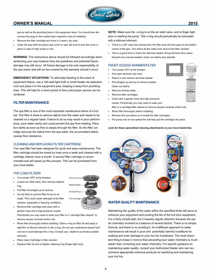
TOP LOAD FILTERS
Turn power OFF at the breaker.
Loosen air relief valve, then remove retainer
ring.
Pull filter lid straight up to remove.
Do not twist or pull the filter lid up on an
angle. This could cause damage to the filter
canister, especially in freezing conditions.
Remove filter cartridge and clean with a
garden hose and a high-pressure nozzle.
Periodically you may need to soak your filter in a “cartridge filter cleaner” to
remove excess minerals and/or oils.
Rinse filter thoroughly before installing. Clean o-ring on filter lid and apply a
light film of silicone lubricant to the o-ring. Do not use a petroleum-based lubri-
cant as it could damage the o-ring. Consult your dealer to purchase suitable
lubricant.
Place clean Cartridge in filter canister.
Replace filter lid and re-tighten retaining ring (finger tight only)
OWNER’S MANUAL 2015
NOTE: Make sure the o-ring is on the air relief valve, and is finger tight
prior to starting the pump. This o-ring should periodically be lubricated
with a silicone lubricant.
There is a 3/8” clear line coming from the filter area and this goes to the bottom
corner of the spa. This drains all the water from around the filter canister.
This is a good time to check the skimmer basket. Bring skimmer door (weir)
forward and unscrew basket. Clean out debris and reinstall.
FRONT ACCESS SKIMMER/FILTER
Turn power OFF at the breaker.
Pull open skimmer weir door.
Reach in and remove skimmer basket.
Pull straight up and out to remove basket.
Clean out debris.
Remove diverter plate.
Remove filter cartridges.
Clean with a garden hose and high-pressure
nozzle. Periodically you may need to soak your
filter in a cartridge filter cleaner to remove excess minerals and/or oils.
Rinse filter thoroughly before installing.
Reverse this procedure to re-install the filter cartridges.
Put pump one on low speed this will help pull the cartridge into place.
Look for these specialized cleaning attachments at your local dealership.
WATER QUALITY MAINTENANCE
Maintaining the quality of the water within the specified limits will serve to
enhance your enjoyment and prolong the life of the hot tub’s equipment.
It is a fairly simple task, but it requires regular attention because the wa-
ter chemistry involved is a balance of several factors. There is no simple
formula, and there is no avoiding it. An indifferent approach to water
maintenance will result in poor and potentially harmful conditions for
soaking and even damage to your hot tub investment. The most impor-
tant thing to keep in mind is that preventing poor water chemistry is much
easier than correcting poor water chemistry. For specific guidance on
maintaining water quality, consult your Authorized Dealer who can rec-
ommend appropriate chemical products for sanitizing and maintaining
your hot tub.
10
MAINTAIN HEALTHY SPA WATER
Important! When maintaining your hot tub’s water chemistry, ensure
that your cover is removed during any aggressive treatments to allow for
dissipation into the air. Take care to remove the cover slowly and let
chemicals deplete if you are uncertain if your water is properly balanced.
Always maintain your hot tub’s water chemistry within the follow-
ing parameters:
pH: pH is a measure of relative acidity or alkalinity of water and is meas-
ured on a scale of 0 to 14. The midpoint of 7 is said to be neutral, above
which is alkaline and below which is acidic. In hot tub water, it is very
important to maintain a slightly alkaline condition of 7.2 to 7.8. Problems
become proportionately severe the further outside of this range the wa-
ter gets. A low pH will be corrosive to metals in the hot tub equipment. A
high pH will cause minerals to deposit on the interior surface (scaling). In
addition, the ability of the sanitation agents to keep the hot tub clean is
severely affected as the pH moves beyond the ideal range. That is why
almost all hot tub water test kits contain a measure for pH as well as
sanitizer.
Sanitizer (Chlorine or Bromine): To destroy bacteria and organic com-
pounds in the hot tub water by breaking them down into non-harmful
levels which get filtered out. A sanitizer must be used regularly, either
chlorine or bromine. Sanitizing your spa water is the most important spa
maintenance you can do for yourself.
Total Alkalinity: This refers to the ability of the hot tub water to resist
changes in pH. Controlling alkalinity can help keep your pH in the appro-
priate range thereby lessening the need for pH balancing. If the TA is
too low the pH level will fluctuate rapidly from high to low. If the TA is too
high the pH will tend to be too high and will be very difficult to bring back
down.
Calcium Hardness: This is a measurement of dissolved calcium in the
water. Calcium will help control the corrosive nature of the spa’s
water.
WARNING: Never store chemicals inside the equipment area of your
spa.
IMPORTANT: Do not use Hydrogen Peroxide based sanitizers in your
spa. When using Chlorine or Bromine tablets you must use a floating
dispenser. These chemicals can have an extremely
corrosive effect on certain materials in the spa. Damage caused by use
of these chemicals, or improper use of any chemicals, is not covered
under the spa’s warranty.
OTHER ADDITIVES: Many other additives are available for your spa.
Some are necessary to compensate for out-of-balance water, some aid
in cosmetic water treatment and others simply alter the feel or smell of
the water. Your Authorized Dealer can advise you on the use of these
additives.
OWNER’S MANUAL 2015
MICROSILK
If your hot tub is equipped with a MicroSilk generator you can take ad-
vantage of some incredible health and appearance benefits. Find ex-
panded information below on the MicroSilk system, benefits and opera-
tion.
ABOUT MICROSILK
MicroSilk produces a silky white cloud of micro bubbles that are small
enough to enter the pores of your skin. When the micro bubbles enter
the pores of your skin they absorb foreign contaminants and release
oxygen. This process improves collagen production, leaving skin feeling
smooth and healthy. Using the MicroSilk System on a regular basis
greatly reduces the appearance of wrinkles and your skin will appear
younger and firmer after only a short period of time.
TREATING SKIN CONDITIONS
MicroSilk is used to treat various skin conditions including: Eczema, Pso-
riasis, Ichthyosis and aids in reducing scar tissue. More information is
available from your local dealership.
OPERATION
MicroSilk is produced by a unique piece of equipment, the MicroSilk
Generator, that roughly resembles a jet pump and is located in your
equipment area. The MicroSilk generator is powered by your hot tub and
controlled using your main control panel.
The MicroSilk Generator requires both water and air to function. Water is
supplied from the water in your hot tub and an independent air line con-
nects from a small grate-like fitting from above your spas’ waterline –
providing the oxygen needed for MicroSilk production.
There is an adjustment valve along the water supply line to the MicroSilk
generator that varies the air/water ratio that enters into the system. This
adjustment is extremely sensitive and turning the adjustment valve only 1
mm can greatly effect the level of MicroSilk production. When your spa
leaves the factory, it has been tested and the valve position marked for
optimum MicroSilk production.
Once activated, you will be able to see a white cloud of silky water com-
ing from the specialized fitting in your spa. Depending on the size of your
hot tub you should see your entire spa filled with oxygen rich micro bub-
bles within minutes (more water capacity equals a longer duration until
the entire hot tub fills with white silky water).
TROUBLESHOOTING
If your spas’ MicroSilk production seems slow, or lower than normal:
Ensure that the air supply line is clear of any debris.
Verify that water is flowing to the MicroSilk generator.
Check the air/water mixture valve. Return to factory settings by aligning factory
placed marks. To adjust: make incremental (1 mm) turns and wait at least 90
seconds before making further adjustments.
Shut power off at breaker and make sure all electrical, water and air lines have
a good connection to the MicroSilk Generator.
11
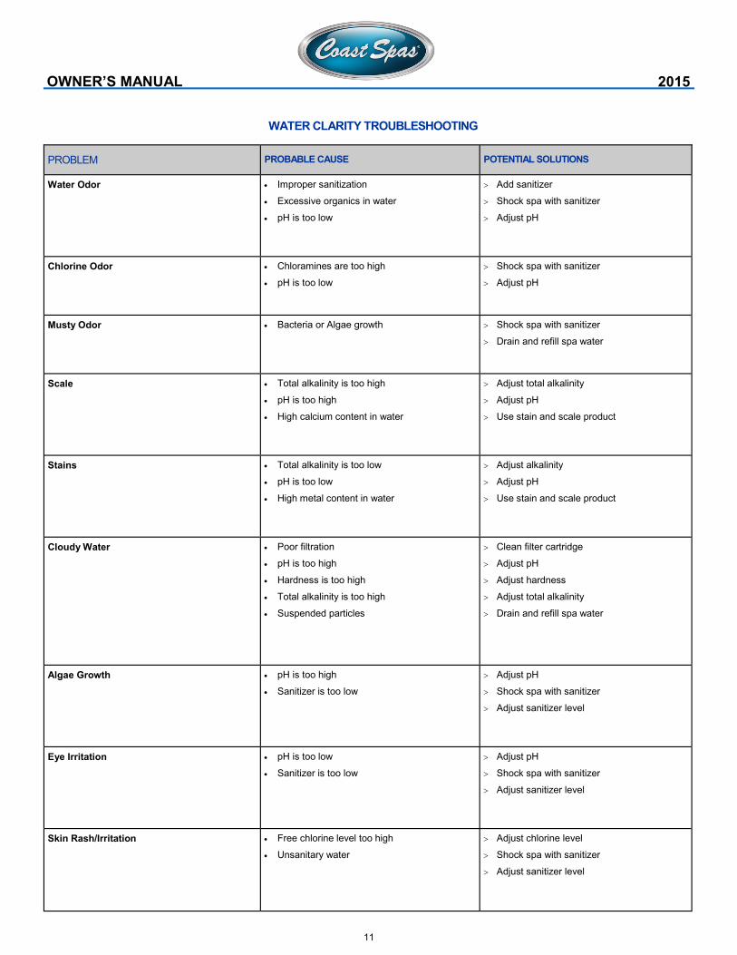
PROBLEM PROBABLE CAUSE POTENTIAL SOLUTIONS
Water Odor Improper sanitization
Excessive organics in water
pH is too low
Add sanitizer
Shock spa with sanitizer
Adjust pH
Chlorine Odor Chloramines are too high
pH is too low
Shock spa with sanitizer
Adjust pH
Musty Odor Bacteria or Algae growth Shock spa with sanitizer
Drain and refill spa water
Scale Total alkalinity is too high
pH is too high
High calcium content in water
Adjust total alkalinity
Adjust pH
Use stain and scale product
Stains Total alkalinity is too low
pH is too low
High metal content in water
Adjust alkalinity
Adjust pH
Use stain and scale product
Cloudy Water Poor filtration
pH is too high
Hardness is too high
Total alkalinity is too high
Suspended particles
Clean filter cartridge
Adjust pH
Adjust hardness
Adjust total alkalinity
Drain and refill spa water
Algae Growth pH is too high
Sanitizer is too low
Adjust pH
Shock spa with sanitizer
Adjust sanitizer level
Eye Irritation pH is too low
Sanitizer is too low
Adjust pH
Shock spa with sanitizer
Adjust sanitizer level
Skin Rash/Irritation Free chlorine level too high
Unsanitary water
Adjust chlorine level
Shock spa with sanitizer
Adjust sanitizer level
WATER CLARITY TROUBLESHOOTING
OWNER’S MANUAL 2015
12
PRODUCT & CARE GUIDE
Your Authorized Dealer carries a wide variety of care and maintenance
products. For more information please contact your Dealer.
REQUIRED FILTER MAINTENANCE
Your new hot tub is equipped with a filter cartridge. To ensure maximum
water quality at all times, you should replace the filter cartridge every six
months, or earlier as necessary. The filter cartridge is designed to be
thrown away! Attempts to re-use the filter cartridge may result in the re-
release of unwanted particles back into the hot tub.
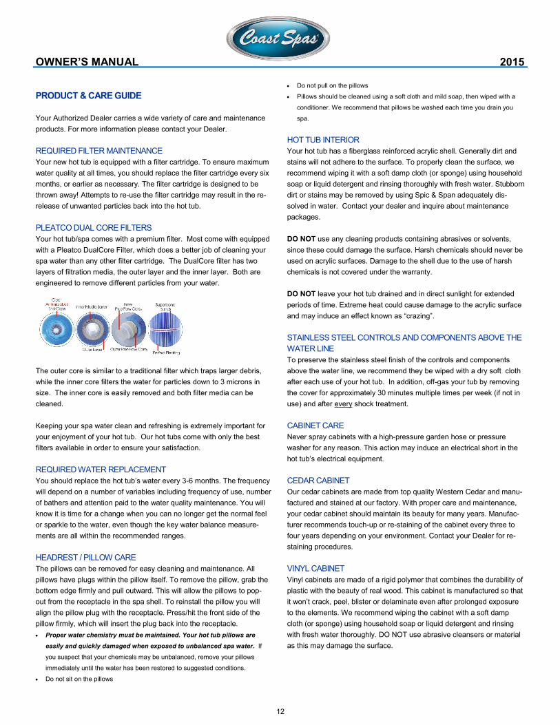
PLEATCO DUAL CORE FILTERS
Your hot tub/spa comes with a premium filter. Most come with equipped
with a Pleatco DualCore Filter, which does a better job of cleaning your
spa water than any other filter cartridge. The DualCore filter has two
layers of filtration media, the outer layer and the inner layer. Both are
engineered to remove different particles from your water.
The outer core is similar to a traditional filter which traps larger debris,
while the inner core filters the water for particles down to 3 microns in
size. The inner core is easily removed and both filter media can be
cleaned.
Keeping your spa water clean and refreshing is extremely important for
your enjoyment of your hot tub. Our hot tubs come with only the best
filters available in order to ensure your satisfaction.
REQUIRED WATER REPLACEMENT
You should replace the hot tub’s water every 3-6 months. The frequency
will depend on a number of variables including frequency of use, number
of bathers and attention paid to the water quality maintenance. You will
know it is time for a change when you can no longer get the normal feel
or sparkle to the water, even though the key water balance measure-
ments are all within the recommended ranges.
HEADREST / PILLOW CARE
The pillows can be removed for easy cleaning and maintenance. All
pillows have plugs within the pillow itself. To remove the pillow, grab the
bottom edge firmly and pull outward. This will allow the pillows to pop-
out from the receptacle in the spa shell. To reinstall the pillow you will
align the pillow plug with the receptacle. Press/hit the front side of the
pillow firmly, which will insert the plug back into the receptacle.
Proper water chemistry must be maintained. Your hot tub pillows are
easily and quickly damaged when exposed to unbalanced spa water. If
you suspect that your chemicals may be unbalanced, remove your pillows
immediately until the water has been restored to suggested conditions.
Do not sit on the pillows
OWNER’S MANUAL 2015
Do not pull on the pillows
Pillows should be cleaned using a soft cloth and mild soap, then wiped with a
conditioner. We recommend that pillows be washed each time you drain you
spa.
HOT TUB INTERIOR
Your hot tub has a fiberglass reinforced acrylic shell. Generally dirt and
stains will not adhere to the surface. To properly clean the surface, we
recommend wiping it with a soft damp cloth (or sponge) using household
soap or liquid detergent and rinsing thoroughly with fresh water. Stubborn
dirt or stains may be removed by using Spic & Span adequately dis-
solved in water. Contact your dealer and inquire about maintenance
packages.
DO NOT use any cleaning products containing abrasives or solvents,
since these could damage the surface. Harsh chemicals should never be
used on acrylic surfaces. Damage to the shell due to the use of harsh
chemicals is not covered under the warranty.
DO NOT leave your hot tub drained and in direct sunlight for extended
periods of time. Extreme heat could cause damage to the acrylic surface
and may induce an effect known as “crazing”.
STAINLESS STEEL CONTROLS AND COMPONENTS ABOVE THE
WATER LINE
To preserve the stainless steel finish of the controls and components
above the water line, we recommend they be wiped with a dry soft cloth
after each use of your hot tub. In addition, off-gas your tub by removing
the cover for approximately 30 minutes multiple times per week (if not in
use) and after every shock treatment.
CABINET CARE
Never spray cabinets with a high-pressure garden hose or pressure
washer for any reason. This action may induce an electrical short in the
hot tub’s electrical equipment.
CEDAR CABINET
Our cedar cabinets are made from top quality Western Cedar and manu-
factured and stained at our factory. With proper care and maintenance,
your cedar cabinet should maintain its beauty for many years. Manufac-
turer recommends touch-up or re-staining of the cabinet every three to
four years depending on your environment. Contact your Dealer for re-
staining procedures.
VINYL CABINET
Vinyl cabinets are made of a rigid polymer that combines the durability of
plastic with the beauty of real wood. This cabinet is manufactured so that
it won’t crack, peel, blister or delaminate even after prolonged exposure
to the elements. We recommend wiping the cabinet with a soft damp
cloth (or sponge) using household soap or liquid detergent and rinsing
with fresh water thoroughly. DO NOT use abrasive cleansers or material
as this may damage the surface.
13
SLATE CABINETS
Optional Slate cabinets are custom-built and painted in our factory. We
recommend lightly brushing the cabinet with a SOFT bristle brush to
remove any dirt or stains. For more information on the care of your Slate
cabinet, please contact your Local Dealer.
COVER CARE
A well cared for spa cover is a thing of beauty in its own right. Be sure to
clean and condition your cover at least once a month – more often if
needed. Your cover needs to be cleaned and conditioned because vinyl
can be dry and become brittle, spoiling your spa’s appearance. Dry,
brittle vinyl can also tear at the seams and stress points. Quality materi-
als, internal sewn reinforcing and careful workmanship can only go so
far against the ravages of Mother Nature. See the specific Warranty card
enclosed with your cover for further details.
When you shock your spa you need to remove the cover for a minimum of 30
minutes to ensure that the chemical gas off can escape from the spa.
You are required to keep the spa covered at all time when not in use to protect
the shell from harmful UV rays.
A covered spa will use less electricity when maintaining the desired water
temperature
See the manual that comes with the cover for proper mounting of the cover
locks
The cover should remain locked at all times to prevent unauthorized entry into
the spa and potential drowning.
Do not Sit, Stand or Lie on your cover. Nor should you place any heavy object
on top of the cover as this may damage the structure.
VERY IMPORTANT: We recommend a vinyl conditioner for your spa
cover. Your local dealer carries a wide variety of care and maintenance
products. Choose a pleasant day each month to remove your cover from
the spa and lay it on a flat surface accessible by garden hose. Douse
the cover with a healthy amount of water from the hose or a bucket to
rinse away loose dirt or debris. Using a soft bristle brush and a mild
solution of dishwashing liquid (about one teaspoon of detergent to two
gallons of water), and with a gentle circular motion, scrub the cover
clean. Be careful not to let any areas of the cover dry before they’re
thoroughly rinsed. Now apply the vinyl conditioner as directed on the
container. Massage the conditioner into the cover in a gentle but firm
manner. Before replacing the cover on your spa, wipe and rinse any dirt
from the bottom of the cover. When you are ready, put the cover on the
spa.
NOTE: To remove tree sap, use lighter fluid (not charcoal lighter but the
fluid used in cigarette lighters). Use sparingly, then immediately apply
conditioner to that area.
GLOSSARY OF TERMS
AIR CONTROL VALVE: Mounted generally on the lip of the spa, it in-
duces warm air from the equipment enclosure into the jet stream through
venturi action.
WATER DIVERTER VALVE: The large diverter is used to divert water to
various seats in the spa.
OWNER’S MANUAL 2015
ON/OFF DIVERTER VALVE: The smaller diverter is used to control
water flow and to turn on/off the neck jets and/or waterfalls.
FILTER AIR RELIEF VALVE: Located on top of dome filter lid. Used to
release air from the filter.
SKIMMER BLEEDER VALVE: Located in the skimmer area, needs to be
loosened while filling the spa. This will help eliminate air from being
trapped in the spa equipment.
OZONATOR: Available as an option. The ozonator produces natural
ozone through the Corona Discharge process. Continuous use of an
ozonator can dramatically reduce sanitizer consumption.
CONTROL BOX (Pack): Basically the “heart” of the spa. Power is distrib-
uted to any/all functions of the spa: pumps, ozonator, LED lighting,
heater element, etc.
CONTROL PANEL: Mounted on the top lip of the spa and controls the
functions of the spa.
DRAIN VALVE: Used in draining of the spa. Normally located in the
equipment area.
EQUIPMENT ENCLOSURE: An enclosure that houses the control box,
pump(s) and other electrical components.
FILTER: The filter cleans the spa by passing water through a filter car-
tridge where debris and impurities are removed. Top load filter means the
filter cartridge is accessible through the top of the spa. Front access
skimmer means cartridge is accessed through door of skimmer.
FLOOR DRAIN: The floor drain is covered by a grate-type cover and is
utilized when draining the spa. It also acts as the return for the ozonator.
You will see bubbles emitted from this drain, which is the result of water
mixing with the ozone output.
GATE VALVES: Red with a grey handle is located at the inlet and outlet
of the pumping system. Used while servicing the spa equipment, the
valves open or close the water flow to the equipment. To remain open for
normal use, turn fully counterclockwise.
KNIFE VALVES: A white “T”-handled valve, same functions as Gate
valve (see above), except to open them you pull up on handle.
HEATER: The electronically controlled heater raises the temperature of
the spa to the desired setting.
LEDs: LEDs and their special lenses can be used to achieve the desired
mood lighting in the spa and spa jets.
SKIMMER: This is the rectangular outlet at the water level. The skimmer
removes surface debris to the filter. The water level in the spa should be
kept ½ to ¾ up on the skimmer for optimum operation.
14
SUCTION FITTING: During operation of the equipment, the suction
works in conjunction with the skimmer to draw water from the bottom of
the spa through the filter, keeping the spa sparkling clean.
NECK JET: Direction-controllable jet for soothing neck massage.
ADJUSTABLE CLUSTER JET: Our adjustable, high-intensity hydro-
therapy jet.
DIRECTIONAL JET: Provides a straight flow for a therapeutic massage
ROTATIONAL JET: Provides a Uni-directional circular therapeutic mas-
sage.
MASSAGE JET: Delivers massage in staccato bursts over a narrow,
focused area.
VOLCANO/WHIRLPOOL JET: high-output jet designed for foot and leg
massage.
LAMINAR FLOW WATER FEATURE: A thin stream of water that arcs
from the spa lip.
OWNER’S MANUAL 2015
15
OWNER’S MANUAL 2015
SYMPTOM PROBABLE CAUSE RECOMMENDED ACTION
Noisy/Loud motor Air trapped in the pump
Low water level
Worn pump seal
Defective pump
Open bleed valve in the skimmer
Add water to the spa
Contact your Dealer
Contact your Dealer
Pumps power down on their own Set temperature has been reached
Filtration cycle has ended
Automatic time out
Overheat safety protection
No problem
No problem
Pumps are set to run for a predetermined time while the
spa is in use (15-20 Mins)
The pumps have a thermal overload which will prevent
them from running for extended periods of time. Wait
until pumps have cooled down (1+ hrs). If problem per-
sists, contact your Dealer.
Pump running constantly, will not
turn off
Filter cycle set to 24 hours
Problem with the circuit board
Turn off 24 hour filtration
Turn power off at GFCI and contact your Dealer
Pump will not turn on GFCI tripped
Motor has overheated
Not plugged in
Damaged plug
Seized motor
Blown fuse
Motor vent is blocked
Reset the GFCI
Let cool for 1+ hour
Plug in to the board
Contact your Dealer
Contact your Dealer
Check fuse or contact your Dealer
Clear debris from the vent
SYMPTOM PROBABLE CAUSE RECOMMENDED ACTION
Spa does not work Power is turned off Reset GFCI
No display on the control panel Power is turned off
Defective topside control
Reset GFCI
Contact your Dealer
Letters on the control panel An error has been found Refer to the Reference Card for your control panel to
verify the error. Contact your Dealer for service
SPA SYSTEM
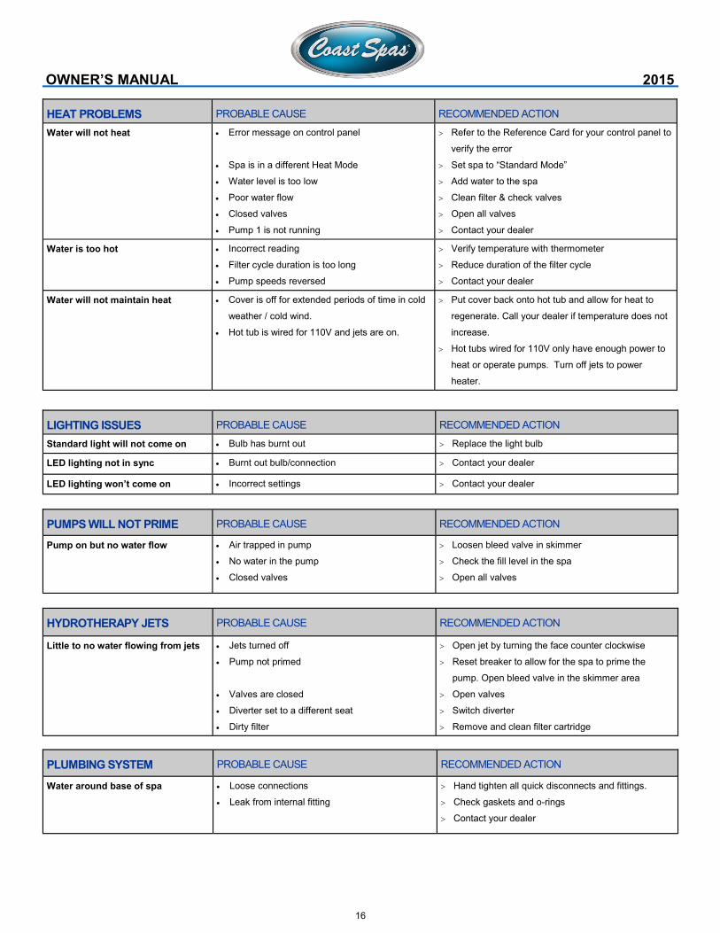
PUMP PROBLEMS
TROUBLESHOOTING GUIDE
16
OWNER’S MANUAL 2015
LIGHTING ISSUES PROBABLE CAUSE RECOMMENDED ACTION
Standard light will not come on Bulb has burnt out Replace the light bulb
LED lighting not in sync Burnt out bulb/connection Contact your dealer
LED lighting won’t come on Incorrect settings Contact your dealer
HEAT PROBLEMS PROBABLE CAUSE RECOMMENDED ACTION
Water will not heat Error message on control panel
Spa is in a different Heat Mode
Water level is too low
Poor water flow
Closed valves
Pump 1 is not running
Refer to the Reference Card for your control panel to
verify the error
Set spa to “Standard Mode”
Add water to the spa
Clean filter & check valves
Open all valves
Contact your dealer
Water is too hot Incorrect reading
Filter cycle duration is too long
Pump speeds reversed
Verify temperature with thermometer
Reduce duration of the filter cycle
Contact your dealer
Water will not maintain heat Cover is off for extended periods of time in cold
weather / cold wind.
Hot tub is wired for 110V and jets are on.
Put cover back onto hot tub and allow for heat to
regenerate. Call your dealer if temperature does not
increase.
Hot tubs wired for 110V only have enough power to
heat or operate pumps. Turn off jets to power
heater.
PUMPS WILL NOT PRIME PROBABLE CAUSE RECOMMENDED ACTION
Pump on but no water flow Air trapped in pump
No water in the pump
Closed valves
Loosen bleed valve in skimmer
Check the fill level in the spa
Open all valves
HYDROTHERAPY JETS PROBABLE CAUSE RECOMMENDED ACTION
Little to no water flowing from jets Jets turned off
Pump not primed
Valves are closed
Diverter set to a different seat
Dirty filter
Open jet by turning the face counter clockwise
Reset breaker to allow for the spa to prime the
pump. Open bleed valve in the skimmer area
Open valves
Switch diverter
Remove and clean filter cartridge
PLUMBING SYSTEM PROBABLE CAUSE RECOMMENDED ACTION
Water around base of spa Loose connections
Leak from internal fitting
Hand tighten all quick disconnects and fittings.
Check gaskets and o-rings
Contact your dealer
17
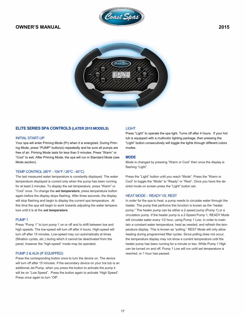
ELITE SERIES SPA CONTROLS (LATER 2015 MODELS)
INITIAL START-UP
Your spa will enter Priming Mode (Pr) when it is energized. During Prim-
ing Mode, press “PUMP” button(s) repeatedly and be sure all pumps are
free of air. Priming Mode lasts for less than 5 minutes. Press “Warm” or
“Cool” to exit. After Priming Mode, the spa will run in Standard Mode (see
Mode section).
TEMP CONTROL (80°F - 104°F / 26°C - 40°C)
The last measured water temperature is constantly displayed. The water
temperature displayed is current only when the pump has been running
for at least 2 minutes. To display the set temperature, press “Warm” or
“Cool” once. To change the set temperature, press temperature button
again before the display stops flashing. After three seconds, the display
will stop flashing and begin to display the current spa temperature. At
this time the spa will begin to work towards adjusting the water tempera-
ture until it is at the set temperature.
PUMP 1
Press “Pump 1” to turn pump 1 on or off and to shift between low and
high speeds. The low-speed will turn off after 4 hours. High-speed will
turn off after 15 minutes. Low-speed may run automatically at times
(filtration cycles, etc.) during which it cannot be deactivated from the
panel, however the “high-speed” mode may be operated.
PUMP 2 & AUX (IF EQUIPPED)
Press the corresponding button once to turn the device on. The device
will turn off after 15 minutes. If the secondary device on your hot tub is an
additional Jet Pump, when you press the button to activate the pump it
will be on “Low Speed”. Press the button again to activate “High Speed”.
Press once again to turn “Off”.
LIGHT
Press “Light” to operate the spa light. Turns off after 4 hours. If your hot
tub is equipped with a multicolor lighting package, then pressing the
“Light” button consecutively will toggle the lights through different colors
modes.
MODE
Mode is changed by pressing “Warm or Cool” then once the display is
flashing “Light”.
Press the “Light” button until you reach “Mode”. Press the “Warm or
Cool” to toggle the “Mode” to “Ready” or “Rest”. Once you have the de-
sired mode on screen press the “Light” button set.
HEAT MODE – READY VS. REST
In order for the spa to heat, a pump needs to circulate water through the
heater. The pump that performs this function is known as the “heater
pump.” The heater pump can be either a 2-speed pump (Pump 1) or a
circulation pump. If the heater pump is a 2-Speed Pump 1, READY Mode
will circulate water every 1/2 hour, using Pump 1 Low, in order to main-
tain a constant water temperature, heat as needed, and refresh the tem-
perature display. This is known as “polling.” REST Mode will only allow
heating during programmed filter cycles. Since polling does not occur,
the temperature display may not show a current temperature until the
heater pump has been running for a minute or two. While Pump 1 High
can be turned on and off, Pump 1 Low will run until set temperature is
reached, or 1 hour has passed.
OWNER’S MANUAL 2015
18
READY-IN-REST MODE
READY/REST appears in the display if the spa is in Rest Mode and the
Jets 1 Button is pressed. It is assumed that the spa is being used and will
heat to set temperature. While Pump 1 High can be turned on and off,
Pump 1 Low will run until set temperature is reached, or 1 hour has
passed. After 1 hour, the System
without polling.
CIRCULATION MODE
If the spa is configured for 24HR circulation, the heater pump generally
runs continuously. Since the heater pump is always running, the spa will
maintain set temperature and heat as needed in Ready Mode,
In Rest Mode, the spa will only heat to set temperature during pro-
grammed filter times, even though the water is being filtered constantly
when in Circulation Mode.
TEMPERATURE RANGE
Temperature Range is changed by pressing “Warm or Cool” then once
the display is flashing “Light”.
Press the “Light” button until you reach “TEMP”. Press the “Warm or
Cool” to toggle the “TEMP” to “High” (Arrow Up) or “Low”(Arrow Down).
Once you have the desired Temperature Range on screen press the
“Light” button set.
DUAL TEMPERATURE RANGES (HIGH VS. LOW)
This system incorporates two temperature range settings with independ-
ent set temperatures. The specific range can be selected on the Settings
screen and is visible on the Main Screen in the upper right corner of the
display.
These ranges can be used for various reasons, with a common use be-
ing a “ready to use” setting vs. a “vacation” setting. Each range maintains
its own set temperature as programmed by the user. This way, when a
range is chosen, the spa will heat to the set temperature associated with
that range.
High Range can be set between 80°F and 104°F.
Low Range can be set between 50°F and 99°F.
More specific Temp Ranges may be determined by the Manufacturer.
Freeze Protection is active in either range.
ADJUSTING FILTRATION
MAIN FILTRATION
Filter cycles are set using a start time and a duration. Start time is indicated by
an “A” or “P” in the bottom right corner of
the display. Duration has no “A” or “P” indication. Each setting can be adjusted
in 15-minute increments. The panel calculates
the end time and displays it automatically.
Filtration Cycles are changed by pressing “Warm or Cool” then once the
display is flashing “Light”.
Press the “Light” button until you reach “FLTR” 1 or 2 as indicated in the
lower right side. Press the “Warm or Cool” to toggle the “FLTR” to
“BEGN”. Press “Warm or Cool” to move to Step 1 or press “Light” to
move to Step 2.
Step 1. BEGN—Press the “Warm or Cool” to set the starting hour. Once
the hour is set Press the “Light” button to move to the starting minute,
minutes are set in 15 minutes increments. Press “Light” to move to Step
2.
Step 2. RUN—HRS—Press the “Warm or Cool” to set duration in hour
(s). Once the hour(s) is set Press the “Light” button to move to the dura-
tion in minutes, minutes are set in 15 minutes increments. Press “Light”
to move to Step 3.
Step 3. F 1—ENDS—”Time”. This screen will verify the end time of the filtra-
tion cycle. F 2 will display for Filtration cycle 2.
FILTER CYCLE 2 - OPTIONAL FILTRATION
Filter Cycle 2 is OFF by default.
It is possible to overlap Filter Cycle 1 and Filter Cycle 2, which will
shorten overall filtration by the overlap amount.
OWNER’S MANUAL 2015
19
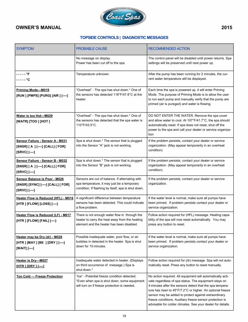
SYMPTOM PROBABLE CAUSE RECOMMENDED ACTION
No message on display.
Power has been cut off to the spa.
The control panel will be disabled until power returns. Spa
settings will be preserved until next power up.
- - - - - °F
- - - - - °C
Temperature unknown. After the pump has been running for 2 minutes, the cur-
rent water temperature will be displayed.
Priming Mode—M019
[RUN ] [PMPS] [PURG] [AIR ] [----]
“Overheat” - The spa has shut down.* One of
the sensors has detected 118°F/47.8°C at the
heater.
Each time the spa is powered up, it will enter Priming
Mode. The purpose of Priming Mode is to allow the user
to run each pump and manually verify that the pump are
primed (air is pureged) and water is flowing.
Water is too Hot—M029
[WATR] [TOO ] [HOT ]
“Overheat” - The spa has shut down.* One of
the sensors has detected that the spa water is
110°F/43.5°C.
DO NOT ENTER THE WATER. Remove the spa cover
and allow water to cool. At 107°F/41.7°C, the spa should
automatically reset. If spa does not reset, shut off the
power to the spa and call your dealer or service organiza-
tion
Sensor Failure - Sensor A - M031
[SNSR] [ A ] [----] [CALL] [ FOR]
[SRVC] [----]
Spa is shut down.* The sensor that is plugged
into the Sensor “A” jack is not working.
If the problem persists, contact your dealer or service
organization. (May appear temporarily in an overheat
condition)
Sensor Failure - Sensor B - M032
[SNSR] [ A ] [----] [CALL] [ FOR]
[SRVC] [----]
Spa is shut down.* The sensor that is plugged
into the Sensor “B” jack is not working.
If the problem persists, contact your dealer or service
organization. (May appear temporarily in an overheat
condition)
Sensor Balance is Poor - M026
[SNSR] [SYNC] [----] [CALL] [ FOR]
[SRVC] [----]
Sensors are out of balance. If alternating with
spa temperature, it may just be a temporary
condition. If flashing by itself, spa is shut down.
If the problem persists, contact your dealer or service
organization.
Heater Flow is Reduced (HFL) - M016
[HTR ] [FLOW] [LOSS] [----]
A significant difference between temperature
sensors has been detected. This could indicate
a flow problem.
If the water level is normal, make sure all pumps have
been primed. If problem persists contact your dealer or
service organization.
Heater Flow is Reduced (LF) - M017
[HTR ] [FLOW] [FAIL] [----]
There is not enough water flow in through the
heater to carry the heat away from the heating
element and the heater has been disabled.
Follow action required for (HFL) message. Heating capa-
bility of the spa will now reset automatically. You may
press any button to reset.
Heater may be Dry (dr) - M028
[HTR ] [MAY ] [BE ] [DRY ] [----]
[WAIT] [----]
Possible inadequate water, poor flow, or air
bubbles in detected in the heater. Spa is shut
down for 15 minutes.
If the water level is normal, make sure all pumps have
been primed. If problem persists contact your dealer or
service organization.
Heater is Dry—M027
[HTR ] [DRY ] [----]
Inadequate water detected in heater. (Displays
on third occurrence of message.) Spa is
shut down.*
Follow action required for (dr) message. Spa will not auto-
matically reset. Press any button to reset manually.
Too Cold — Freeze Protection “Ice” - Potential freeze condition detected.
*Even when spa is shut down, some equipment
will turn on if freeze protection is needed.
No action required. All equipment will automatically acti-
vate regardless of spa status. The equipment stays on
4 minutes after the sensors detect that the spa tempera-
ture has risen to 45°F/7.2°C or higher. An optional freeze
sensor may be added to protect against extraordinary
freeze conditions. Auxiliary freeze sensor protection is
advisable for colder climates. See your dealer for details.
OWNER’S MANUAL 2015
TOPSIDE CONTROLS | DIAGNOSTIC MESSAGES
20
ELITE SERIES SPA CONTROLS (EARLY 2015)
INITIAL START-UP
Your spa will enter Priming Mode (Pr) when it is energized. During Prim-
ing Mode, press “PUMP” button(s) repeatedly and be sure all pumps are
free of air. Priming Mode lasts for less than 5 minutes. Press “Warm” or
“Cool” to exit. After Priming Mode, the spa will run in Standard Mode
(see Mode section).
TEMP CONTROL (80°F - 104°F / 26°C - 40°C)
The last measured water temperature is constantly displayed. The water
temperature displayed is current only when the pump has been running
for at least 2 minutes. To display the set temperature, press “Warm” or
“Cool” once. To change the set temperature, press temperature button
again before the display stops flashing. After three seconds, the display
will stop flashing and begin to display the current spa temperature. At
this time the spa will begin to work towards adjusting the water tempera-
ture until it is at the set temperature.
PUMP 1
Press “Pump 1” to turn pump 1 on or off and to shift between low and
high speeds. The low-speed will turn off after 4 hours. High-speed will
turn off after 15 minutes. Low-speed may run automatically at times
(filtration cycles, etc.) during which it cannot be deactivated from the
panel, however the “high-speed” mode may be operated.
PUMP 2 & AUX (IF EQUIPPED)
Press the corresponding button once to turn the device on. The device
will turn off after 15 minutes. If the secondary device on your hot tub is
an additional Jet Pump, when you press the button to activate the pump
it will be on “Low Speed”. Press the button again to activate “High
Speed”. Press once again to turn “Off”.
OWNER’S MANUAL 2015
LIGHT
Press “Light” to operate the spa light. Turns off after 4 hours. If your hot
tub is equipped with a multicolor lighting package, then pressing the
“Light” button consecutively will toggle the lights through different colors
modes.
MODE
Mode is changed by pressing “Temp” then “Pump”. Press the “Temp”
button to toggle through the available modes. Press “Pump” to exit pro-
gramming.
Standard Mode maintains set temperature. “St” will be displayed mo-
mentarily when you switch into Standard Mode.
Economy Mode heats the spa to the set temperature only during filter
cycles. “Ec” will display when water temp is not current, and will alternate
with water temp when the pump is running.
Sleep Mode heats the spa to within 20°F/10°C of the set temperature
only during filter cycles. “SL” will display when water temp is not current,
and will alternate with water temp when the pump is running.
PRESET FILTER CYCLES
The first preset filter cycle begins 6 minutes after the spa is energized.
The second preset filter cycle begins 12 hours later. Filter duration is
programmable for 1, 2, 3, 4, 5, 6, 7, or 8 hours. The default filter time is 1
hour. To program, press “Temp” then “Pump”. Press “Temp” to adjust.
Press “Pump” to exit programming.
LUXURY SERIES SPA CONTROLS
THE MAIN SCREEN - SPA STATUS
Important information about spa operation can be seen on the Main
Screen. Most features, including Set Temperature adjustment, can be
accessed from this screen. The actual water temperature and Set Tem-
perature can be seen, and the Set Temperature can be adjusted. Time-of
-Day, Ozone and Filter status is available, along with other messages
and alerts. The selected Temperature Range is indicated in the upper
right corner. The Jets Icon in the center will spin if any pump is running
and changes color when the heater is on. A Lock icon is visible if the
panel or settings are locked. The Menu choices on the right can be se-
lected and the screen will change to show more detailed controls or pro-
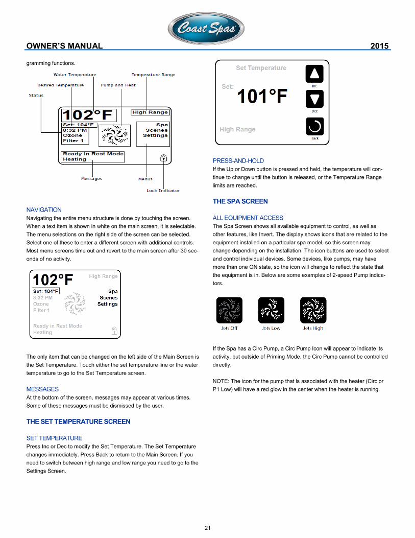
21
gramming functions.
NAVIGATION
Navigating the entire menu structure is done by touching the screen.
When a text item is shown in white on the main screen, it is selectable.
The menu selections on the right side of the screen can be selected.
Select one of these to enter a different screen with additional controls.
Most menu screens time out and revert to the main screen after 30 sec-
onds of no activity.
The only item that can be changed on the left side of the Main Screen is
the Set Temperature. Touch either the set temperature line or the water
temperature to go to the Set Temperature screen.
MESSAGES
At the bottom of the screen, messages may appear at various times.
Some of these messages must be dismissed by the user.
THE SET TEMPERATURE SCREEN
SET TEMPERATURE
Press Inc or Dec to modify the Set Temperature. The Set Temperature
changes immediately. Press Back to return to the Main Screen. If you
need to switch between high range and low range you need to go to the
Settings Screen.
OWNER’S MANUAL 2015
PRESS-AND-HOLD
If the Up or Down button is pressed and held, the temperature will con-
tinue to change until the button is released, or the Temperature Range
limits are reached.
THE SPA SCREEN
ALL EQUIPMENT ACCESS
The Spa Screen shows all available equipment to control, as well as
other features, like Invert. The display shows icons that are related to the
equipment installed on a particular spa model, so this screen may
change depending on the installation. The icon buttons are used to select
and control individual devices. Some devices, like pumps, may have
more than one ON state, so the icon will change to reflect the state that
the equipment is in. Below are some examples of 2-speed Pump indica-
tors.
If the Spa has a Circ Pump, a Circ Pump Icon will appear to indicate its
activity, but outside of Priming Mode, the Circ Pump cannot be controlled
directly.
NOTE: The icon for the pump that is associated with the heater (Circ or
P1 Low) will have a red glow in the center when the heater is running.
22
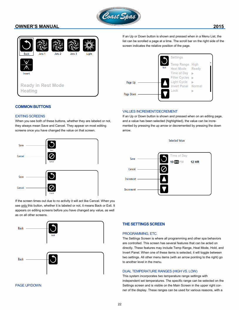
COMMON BUTTONS
EXITING SCREENS
When you see both of these buttons, whether they are labeled or not,
they always mean Save and Cancel. They appear on most editing
screens once you have changed the value on that screen.
If the screen times out due to no activity it will act like Cancel. When you
see only this button, whether it is labeled or not, it means Back or Exit. It
appears on editing screens before you have changed any value, as well
as on all other screens.
PAGE UP/DOWN
OWNER’S MANUAL 2015
If an Up or Down button is shown and pressed when in a Menu List, the
list can be scrolled a page at a time. The scroll bar on the right side of the
screen indicates the relative position of the page.
VALUES INCREMENT/DECREMENT
If an Up or Down button is shown and pressed when on an editing page,
and a value has been selected (highlighted), the value can be incre-
mented by pressing the up arrow or decremented by pressing the down
arrow.
THE SETTINGS SCREEN
PROGRAMMING, ETC.
The Settings Screen is where all programming and other spa behaviors
are controlled. This screen has several features that can be acted on
directly. These features may include Temp Range, Heat Mode, Hold, and
Invert Panel. When one of these items is selected, it will toggle between
two settings. All other menu items (with an arrow pointing to the right) go
to another level in the menu.
DUAL TEMPERATURE RANGES (HIGH VS. LOW)
This system incorporates two temperature range settings with
independent set temperatures. The specific range can be selected on the
Settings screen and is visible on the Main Screen in the upper right cor-
ner of the display. These ranges can be used for various reasons, with a
23
common use being a “ready to use” setting vs. a “vacation” setting. Each
range maintains its own set temperature as programmed by the user.
This way, when a range is chosen, the spa will heat to the set tempera-
ture associated with that range.
High Range can be set between 80°F and 104°F.
Low Range can be set between 50°F and 99°F.
More specific Temp Ranges may be determined by the
Manufacturer. Freeze Protection is active in either range.
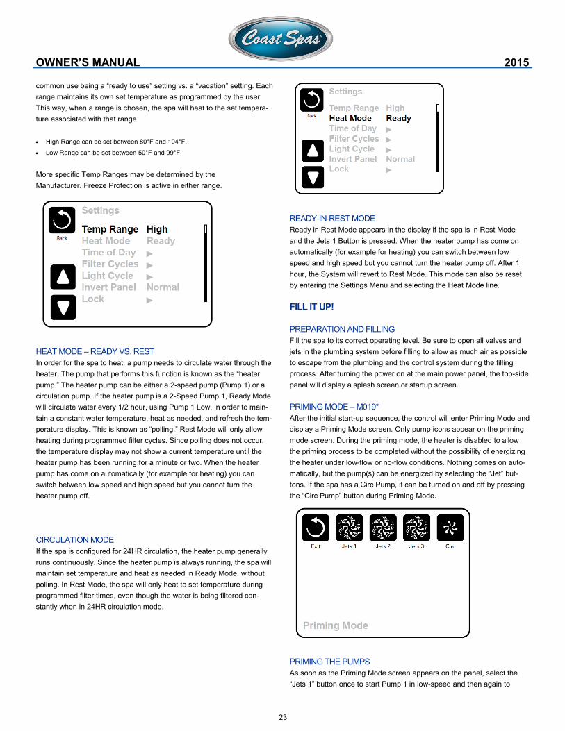
HEAT MODE – READY VS. REST
In order for the spa to heat, a pump needs to circulate water through the
heater. The pump that performs this function is known as the “heater
pump.” The heater pump can be either a 2-speed pump (Pump 1) or a
circulation pump. If the heater pump is a 2-Speed Pump 1, Ready Mode
will circulate water every 1/2 hour, using Pump 1 Low, in order to main-
tain a constant water temperature, heat as needed, and refresh the tem-
perature display. This is known as “polling.” Rest Mode will only allow
heating during programmed filter cycles. Since polling does not occur,
the temperature display may not show a current temperature until the
heater pump has been running for a minute or two. When the heater
pump has come on automatically (for example for heating) you can
switch between low speed and high speed but you cannot turn the
heater pump off.
CIRCULATION MODE
If the spa is configured for 24HR circulation, the heater pump generally
runs continuously. Since the heater pump is always running, the spa will
maintain set temperature and heat as needed in Ready Mode, without
polling. In Rest Mode, the spa will only heat to set temperature during
programmed filter times, even though the water is being filtered con-
stantly when in 24HR circulation mode.
OWNER’S MANUAL 2015
READY-IN-REST MODE
Ready in Rest Mode appears in the display if the spa is in Rest Mode
and the Jets 1 Button is pressed. When the heater pump has come on
automatically (for example for heating) you can switch between low
speed and high speed but you cannot turn the heater pump off. After 1
hour, the System will revert to Rest Mode. This mode can also be reset
by entering the Settings Menu and selecting the Heat Mode line.
FILL IT UP!
PREPARATION AND FILLING
Fill the spa to its correct operating level. Be sure to open all valves and
jets in the plumbing system before filling to allow as much air as possible
to escape from the plumbing and the control system during the filling
process. After turning the power on at the main power panel, the top-side
panel will display a splash screen or startup screen.
PRIMING MODE – M019*
After the initial start-up sequence, the control will enter Priming Mode and
display a Priming Mode screen. Only pump icons appear on the priming
mode screen. During the priming mode, the heater is disabled to allow
the priming process to be completed without the possibility of energizing
the heater under low-flow or no-flow conditions. Nothing comes on auto-
matically, but the pump(s) can be energized by selecting the “Jet” but-
tons. If the spa has a Circ Pump, it can be turned on and off by pressing
the “Circ Pump” button during Priming Mode.
PRIMING THE PUMPS
As soon as the Priming Mode screen appears on the panel, select the
“Jets 1” button once to start Pump 1 in low-speed and then again to
24
switch to high-speed. Also, select the other pumps, to turn them on. The
pumps should be running in high-speed to facilitate priming. If the pumps
have not primed after 2 minutes, and water is not flowing from the jets in
the spa, do not allow the pumps to continue to run. Turn off the pumps
and repeat the process. Note: Turning the power off and back on again
will initiate a new pump priming session. Sometimes momentarily turning
the pump off and on will help it to prime. Do not do this more than 5
times. If the pump(s) will not prime, shut off the power to the spa and call
for service. Important: A pump should not be allowed to run without prim-
ing for more than 2 minutes. Under NO circumstances should a pump be
allowed to run without priming beyond the end of the 4-5 minute priming
mode. Doing so may cause damage to the pump and cause the system
to energize the heater and go into an overheat condition.
EXITING PRIMING MODE
The system will automatically enter the normal heating and filtering at
the end of the priming mode, which lasts 4-5 minutes. You can manually
exit Priming Mode by pressing the “Exit” button on the Priming Mode
Screen. Note that if you do not manually exit the priming mode as de-
scribed above, the priming mode will be automatically terminated after 4
-5 minutes. Be sure that the pump(s) have been primed by this time.
Once the system has exited Priming Mode, the top-side panel will dis-
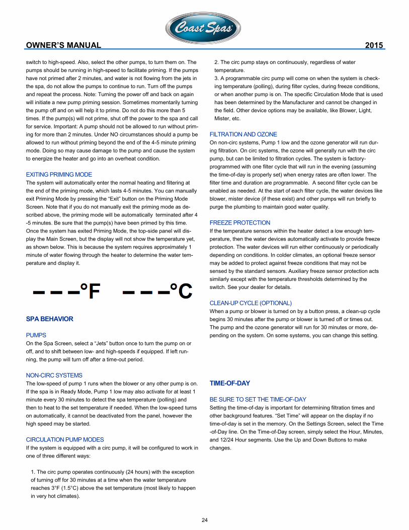
play the Main Screen, but the display will not show the temperature yet,
as shown below. This is because the system requires approximately 1
minute of water flowing through the heater to determine the water tem-
perature and display it.
SPA BEHAVIOR
PUMPS
On the Spa Screen, select a “Jets” button once to turn the pump on or
off, and to shift between low- and high-speeds if equipped. If left run-
ning, the pump will turn off after a time-out period.
NON-CIRC SYSTEMS
The low-speed of pump 1 runs when the blower or any other pump is on.
If the spa is in Ready Mode, Pump 1 low may also activate for at least 1
minute every 30 minutes to detect the spa temperature (polling) and
then to heat to the set temperature if needed. When the low-speed turns
on automatically, it cannot be deactivated from the panel, however the
high speed may be started.
CIRCULATION PUMP MODES
If the system is equipped with a circ pump, it will be configured to work in
one of three different ways:
1. The circ pump operates continuously (24 hours) with the exception
of turning off for 30 minutes at a time when the water temperature
reaches 3°F (1.5°C) above the set temperature (most likely to happen
in very hot climates).
OWNER’S MANUAL 2015
2. The circ pump stays on continuously, regardless of water
temperature.
3. A programmable circ pump will come on when the system is check-
ing temperature (polling), during filter cycles, during freeze conditions,
or when another pump is on. The specific Circulation Mode that is used
has been determined by the Manufacturer and cannot be changed in
the field. Other device options may be available, like Blower, Light,
Mister, etc.
FILTRATION AND OZONE
On non-circ systems, Pump 1 low and the ozone generator will run dur-
ing filtration. On circ systems, the ozone will generally run with the circ
pump, but can be limited to filtration cycles. The system is factory-
programmed with one filter cycle that will run in the evening (assuming
the time-of-day is properly set) when energy rates are often lower. The
filter time and duration are programmable. A second filter cycle can be
enabled as needed. At the start of each filter cycle, the water devices like
blower, mister device (if these exist) and other pumps will run briefly to
purge the plumbing to maintain good water quality.
FREEZE PROTECTION
If the temperature sensors within the heater detect a low enough tem-
perature, then the water devices automatically activate to provide freeze
protection. The water devices will run either continuously or periodically
depending on conditions. In colder climates, an optional freeze sensor
may be added to protect against freeze conditions that may not be
sensed by the standard sensors. Auxiliary freeze sensor protection acts
similarly except with the temperature thresholds determined by the
switch. See your dealer for details.
CLEAN-UP CYCLE (OPTIONAL)
When a pump or blower is turned on by a button press, a clean-up cycle
begins 30 minutes after the pump or blower is turned off or times out.
The pump and the ozone generator will run for 30 minutes or more, de-
pending on the system. On some systems, you can change this setting.
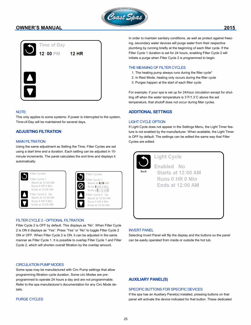
TIME-OF-DAY
BE SURE TO SET THE TIME-OF-DAY
Setting the time-of-day is important for determining filtration times and
other background features. “Set Time” will appear on the display if no
time-of-day is set in the memory. On the Settings Screen, select the Time
-of-Day line. On the Time-of-Day screen, simply select the Hour, Minutes,
and 12/24 Hour segments. Use the Up and Down Buttons to make
changes.
25
NOTE:
This only applies to some systems: If power is interrupted to the system,
Time-of-Day will be maintained for several days.
ADJUSTING FILTRATION
MAIN FILTRATION
Using the same adjustment as Setting the Time, Filter Cycles are set
using a start time and a duration. Each setting can be adjusted in 15-
minute increments. The panel calculates the end time and displays it
automatically.
FILTER CYCLE 2 - OPTIONAL FILTRATION
Filter Cycle 2 is OFF by default. This displays as “No”. When Filter Cycle
2 is ON it displays as “Yes”. Press “Yes” or “No” to toggle Filter Cycle 2
ON or OFF. When Filter Cycle 2 is ON, it can be adjusted in the same
manner as Filter Cycle 1. It is possible to overlap Filter Cycle 1 and Filter
Cycle 2, which will shorten overall filtration by the overlap amount.
CIRCULATION PUMP MODES
Some spas may be manufactured with Circ Pump settings that allow
programming filtration cycle duration. Some circ Modes are pre-
programmed to operate 24 hours a day and are not programmable.
Refer to the spa manufacturer’s documentation for any Circ Mode de-
tails.
PURGE CYCLES
OWNER’S MANUAL 2015
In order to maintain sanitary conditions, as well as protect against freez-
ing, secondary water devices will purge water from their respective
plumbing by running briefly at the beginning of each filter cycle. If the
Filter Cycle 1 duration is set for 24 hours, enabling Filter Cycle 2 will
initiate a purge when Filter Cycle 2 is programmed to begin.
THE MEANING OF FILTER CYCLES
1. The heating pump always runs during the filter cycle*
2. In Rest Mode, heating only occurs during the filter cycle
3. Purges happen at the start of each filter cycle
For example, if your spa is set up for 24/hour circulation except for shut-
ting off when the water temperature is 3˚F/1.3˚C above the set
temperature, that shutoff does not occur during filter cycles.
ADDITIONAL SETTINGS
LIGHT CYCLE OPTION
If Light Cycle does not appear in the Settings Menu, the Light Timer fea-
ture is not enabled by the manufacturer. When available, the Light Timer
is OFF by default. The settings can be edited the same way that Filter
Cycles are edited.
INVERT PANEL
Selecting Invert Panel will flip the display and the buttons so the panel
can be easily operated from inside or outside the hot tub.
AUXILIARY PANEL(S)
SPECIFIC BUTTONS FOR SPECIFIC DEVICES
If the spa has an Auxiliary Panel(s) installed, pressing buttons on that
panel will activate the device indicated for that button. These dedicated
26
buttons will operate just like the Spa Screen buttons and the equipment
will behave in the same manner with each button press.
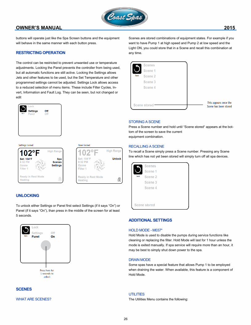
RESTRICTING OPERATION
The control can be restricted to prevent unwanted use or temperature
adjustments. Locking the Panel prevents the controller from being used,
but all automatic functions are still active. Locking the Settings allows
Jets and other features to be used, but the Set Temperature and other
programmed settings cannot be adjusted. Settings Lock allows access
to a reduced selection of menu items. These include Filter Cycles, In-
vert, Information and Fault Log. They can be seen, but not changed or
edit
UNLOCKING
To unlock either Settings or Panel first select Settings (if it says “On”) or
Panel (if it says “On”), than press in the middle of the screen for at least
5 seconds.
SCENES
WHAT ARE SCENES?
OWNER’S MANUAL 2015
Scenes are stored combinations of equipment states. For example if you
want to have Pump 1 at high speed and Pump 2 at low speed and the
Light ON, you could store that in a Scene and recall this combination at
any time.
STORING A SCENE
Press a Scene number and hold until “Scene stored“ appears at the bot-
tom of the screen to save the current
equipment combination.
RECALLING A SCENE
To recall a Scene simply press a Scene number. Pressing any Scene
line which has not yet been stored will simply turn off all spa devices.
ADDITIONAL SETTINGS
HOLD MODE - M037*
Hold Mode is used to disable the pumps during service functions like
cleaning or replacing the filter. Hold Mode will last for 1 hour unless the
mode is exited manually. If spa service will require more than an hour, it
may be best to simply shut down power to the spa.
DRAIN MODE
Some spas have a special feature that allows Pump 1 to be employed
when draining the water. When available, this feature is a component of
Hold Mode.
UTILITIES
The Utilities Menu contains the following:
27
A/B TEMPS
When this is set to On, the main screen will display sensor A and sensor
B temperatures simultaneously. Sensor A is at the opposite end of the
heater from sensor B.
DEMO MODE
Demo Mode is not always enabled, so it may not appear. This is de-
signed to operate several devices in a sequence in order to demonstrate
the various features of a particular hot tub.
FAULT LOG
The Fault Log is a record of the last 24 faults that can be reviewed by a
service tech. Use the Up and Down buttons to view each of the Faults.
When Priming Mode shows in the Fault Log, it is not a fault. Rather, it is
used to keep track of spa restarts.
GFCI TEST
(Feature not available on CE rated systems.)
Your systems may have GFCI configured in one of three ways:
1. GFCI test is not enabled
2. Manual GFCI test is enabled but automatic GFCI test is not enabled
3. Both manual and automatic GFCI tests are enabled. The automatic
test will happen within 7 days of the spa being installed and if success-
ful will not repeat. (If the automatic test fails it will repeat after the spa
is restarted.) GFCI Test will not appear on the screen if it is not en-
abled. This screen allows the GFCI to be tested manually from the
panel and can be used to reset the automatic test feature.
*M0XX is a Message Code. Codes like this will be seen in the Fault Log
ADDITIONAL SETTINGS
PREFERENCES
The Preferences Menu allows the user to change certain parameters
based on personal preference.
TEMP DISPLAY
Change the temperature between Fahrenheit and Celsius.
TIME DISPLAY
Change the clock between 12 hr and 24 hr display.
REMINDERS
OWNER’S MANUAL 2015
Turn the reminder messages (like “Clean Filter”) On or Off.
CLEANUP
Cleanup Cycle Duration is not always enabled, so it may not appear.
When it is available, set the length of time Pump 1 will run after each use.
0-4 hours are available.
DOLPHIN II AND DOLPHIN III (APPLIES TO RF DOLPHIN ONLY)
When set to 0, no addressing is used. Use this setting for a Dolphin II or
Dolphin III which is factory set for no address by default. When set be-
tween 1 and 7, the number is the address. (See the Dolphin manual for
details.)
COLOR
Selecting Color will cycle through 5 background colors available in the
control.
LANGUAGE
Change the language displayed on the panel.
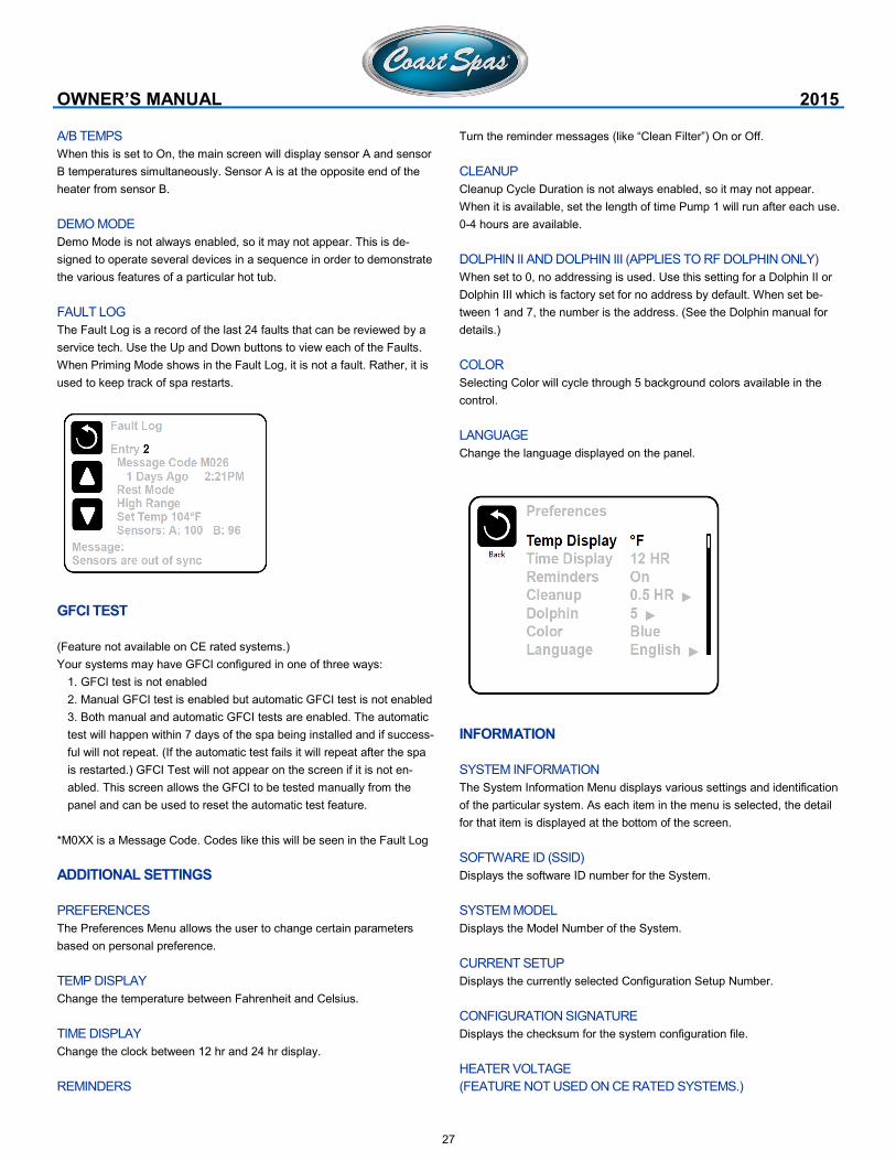
INFORMATION
SYSTEM INFORMATION
The System Information Menu displays various settings and identification
of the particular system. As each item in the menu is selected, the detail
for that item is displayed at the bottom of the screen.
SOFTWARE ID (SSID)
Displays the software ID number for the System.
SYSTEM MODEL
Displays the Model Number of the System.
CURRENT SETUP
Displays the currently selected Configuration Setup Number.
CONFIGURATION SIGNATURE
Displays the checksum for the system configuration file.
HEATER VOLTAGE
(FEATURE NOT USED ON CE RATED SYSTEMS.)
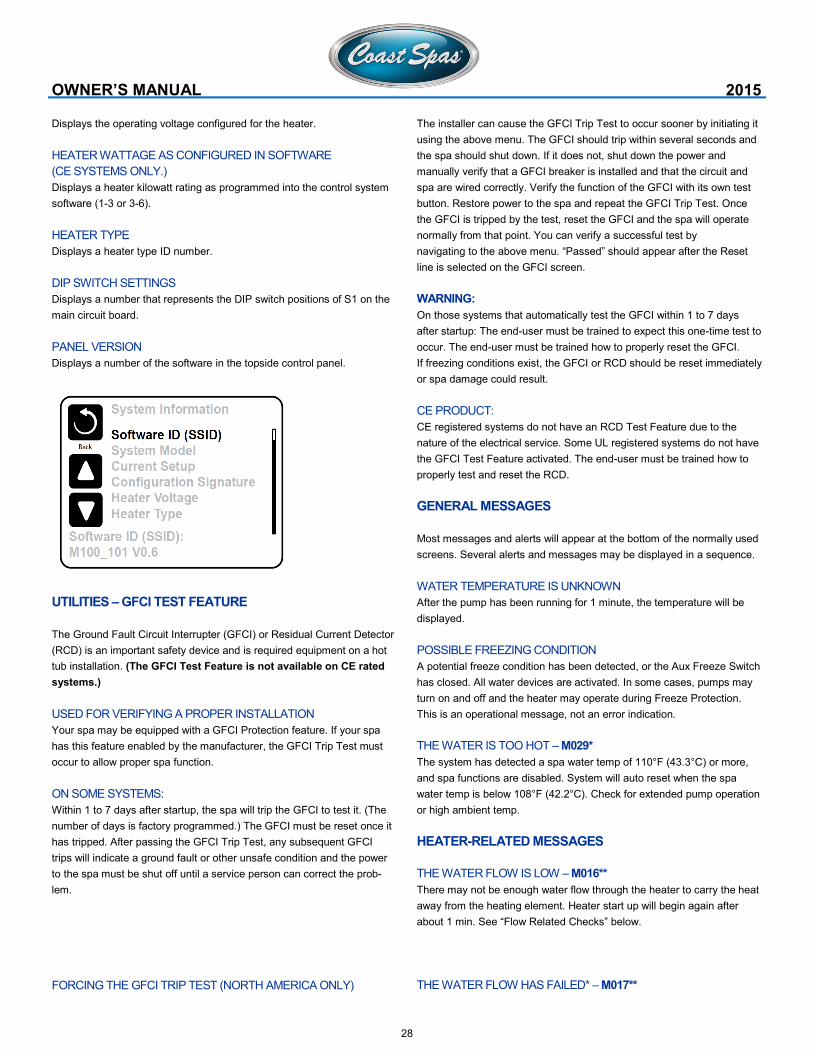
28
Displays the operating voltage configured for the heater.
HEATER WATTAGE AS CONFIGURED IN SOFTWARE
(CE SYSTEMS ONLY.)
Displays a heater kilowatt rating as programmed into the control system
software (1-3 or 3-6).
HEATER TYPE
Displays a heater type ID number.
DIP SWITCH SETTINGS
Displays a number that represents the DIP switch positions of S1 on the
main circuit board.
PANEL VERSION
Displays a number of the software in the topside control panel.
UTILITIES – GFCI TEST FEATURE
The Ground Fault Circuit Interrupter (GFCI) or Residual Current Detector
(RCD) is an important safety device and is required equipment on a hot
tub installation. (The GFCI Test Feature is not available on CE rated
systems.)
USED FOR VERIFYING A PROPER INSTALLATION
Your spa may be equipped with a GFCI Protection feature. If your spa
has this feature enabled by the manufacturer, the GFCI Trip Test must
occur to allow proper spa function.
ON SOME SYSTEMS:
Within 1 to 7 days after startup, the spa will trip the GFCI to test it. (The
number of days is factory programmed.) The GFCI must be reset once it
has tripped. After passing the GFCI Trip Test, any subsequent GFCI
trips will indicate a ground fault or other unsafe condition and the power
to the spa must be shut off until a service person can correct the prob-
lem.
FORCING THE GFCI TRIP TEST (NORTH AMERICA ONLY)
OWNER’S MANUAL 2015
The installer can cause the GFCI Trip Test to occur sooner by initiating it
using the above menu. The GFCI should trip within several seconds and
the spa should shut down. If it does not, shut down the power and
manually verify that a GFCI breaker is installed and that the circuit and
spa are wired correctly. Verify the function of the GFCI with its own test
button. Restore power to the spa and repeat the GFCI Trip Test. Once
the GFCI is tripped by the test, reset the GFCI and the spa will operate
normally from that point. You can verify a successful test by
navigating to the above menu. “Passed” should appear after the Reset
line is selected on the GFCI screen.
WARNING:
On those systems that automatically test the GFCI within 1 to 7 days
after startup: The end-user must be trained to expect this one-time test to
occur. The end-user must be trained how to properly reset the GFCI.
If freezing conditions exist, the GFCI or RCD should be reset immediately
or spa damage could result.
CE PRODUCT:
CE registered systems do not have an RCD Test Feature due to the
nature of the electrical service. Some UL registered systems do not have
the GFCI Test Feature activated. The end-user must be trained how to
properly test and reset the RCD.
GENERAL MESSAGES
Most messages and alerts will appear at the bottom of the normally used
screens. Several alerts and messages may be displayed in a sequence.
WATER TEMPERATURE IS UNKNOWN
After the pump has been running for 1 minute, the temperature will be
displayed.
POSSIBLE FREEZING CONDITION
A potential freeze condition has been detected, or the Aux Freeze Switch
has closed. All water devices are activated. In some cases, pumps may
turn on and off and the heater may operate during Freeze Protection.
This is an operational message, not an error indication.
THE WATER IS TOO HOT – M029*
The system has detected a spa water temp of 110°F (43.3°C) or more,
and spa functions are disabled. System will auto reset when the spa
water temp is below 108°F (42.2°C). Check for extended pump operation
or high ambient temp.
HEATER-RELATED MESSAGES
THE WATER FLOW IS LOW – M016**
There may not be enough water flow through the heater to carry the heat
away from the heating element. Heater start up will begin again after
about 1 min. See “Flow Related Checks” below.
THE WATER FLOW HAS FAILED* – M017**
29
There is not enough water flow through the heater to carry the heat
away from the heating element and the heater has been disabled. See
“Flow Related Checks” below. After the problem has been resolved,
reset the message*.
THE HEATER MAY BE DRY* – M028**
Possible dry heater, or not enough water in the heater to start it. The spa
is shut down for 15 min. Reset this message* to reset the heater start-
up. See “Flow Related Checks” below.
THE HEATER IS DRY* – M027**
There is not enough water in the heater to start it. The spa is shut down.
After the problem has been resolved, you must reset the message* to
restart heater start up. See “Flow Related Checks” below.
THE HEATER IS TOO HOT* – M030**
One of the water temp sensors has detected 118°f (47.8°C) in the heater
and the spa is shut down. You must reset the message* when water is
below 108°f (42.2°C). See “Flow Related Checks” below.
FLOW-RELATED CHECKS
Check for low water level, suction flow restrictions, closed valves,
trapped air, too many closed jets and pump prime. On some systems,
even when spa is shut down by an error condition, some equipment may
occasionally turn on to continue monitoring temperature or if freeze pro-
tection is needed.
*M0XX is a Message Code. Codes like this will be seen in the Fault Log
Some messages can be reset from the panel. Messages that can be
reset will appear with a “right arrow” at the end of the message. Press
the message text to reset the message.
SENSOR-RELATED MESSAGES
SENSORS ARE OUT OF SYNC – M015**
The temperature sensors MAY be out of sync by 3°F. Call for Service.
SENSORS ARE OUT OF SYNC -- CALL FOR SERVICE* – M026**
The temperature sensors ARE out of sync. The fault above has been
established for at least 1 hour. Call for Service.
SENSOR A FAULT, SENOR B FAULT – SENSOR A: M031**, SEN-
SOR B: M032**
A temperature sensor or sensor circuit has failed. Call for Service.
MISCELLANEOUS MESSAGES
COMMUNICATIONS ERROR
The control panel is not receiving communication from the System. Call
for Service.
TEST SOFTWARE INSTALLED
The Control System is operating with test software. Call for Service.
OWNER’S MANUAL 2015
°F OR °C IS REPLACED BY °T
The Control System is in Test Mode. Call for Service.
**M0XX is a Message Code. Codes like this will be seen in the Fault Log
SYSTEM-RELATED MESSAGES
PROGRAM MEMORY FAILURE* – M022**
At Power-Up, the system has failed the Program Checksum Test. This
indicates a problem with the firmware (operation program) and requires a
service call.
THE CLOCK HAS FAILED* – M020**
Contact your dealer or service organization.
THE GFCI TEST FAILED (SYSTEM COULD NOT TEST THE GFCI) –
M036**
(North America Only) May indicate an unsafe installation. Contact your
dealer or service organization.
HOT FAULT – M035**
A Pump Appears to have been Stuck ON when spa was last powered
POWER DOWN THE SPA. DO NOT ENTER THE WATER. Contact your
dealer or service organization.
A PUMP MAY BE STUCK ON – M034**
Water may be overheated. POWER DOWN THE SPA. DO NOT ENTER
THE WATER. Contact your dealer or service organization.
CONFIGURATION ERROR (SPA WILL NOT START UP)
Contact your dealer or service organization.
THE SETTINGS HAVE BEEN RESET (PERSISTENT MEMORY ER-
ROR)* – M021**
Contact your dealer or service organization if this message appears on
more than one power-up.
REMINDER MESSAGES
GENERAL MAINTENANCE HELPS.
Reminder Messages can be suppressed by using the Preferences Menu.
Reminder Messages can be chosen individually by the Manufacturer.
They may be disabled entirely, or there may be a limited number of re-
minders on a specific model. The frequency of each reminder (i.e. 7
days) can be specified by the Manufacturer.
CHECK THE PH
May appear on a regular schedule, i.e. every 7 days. Check pH with a
test kit and adjust pH with the appropriate chemicals.
CHECK THE SANITIZER
May appear on a regular schedule, i.e. every 7 days. Check sanitizer
level and other water chemistry with a test kit and adjust with the appro-
priate chemicals.

30
EcoClean Operation Salt Chlorinating System for Residential Spas
The natural alternative to maintaining clean and clear water in your spa.
MODEL ST1 REGISTRATION NUMBER 27899.02 PEST CONTROL PRODUCTS ACT.
SECTION 01
Introduction & Important Safety Instructions
Health
General
Hyperthermia & Important Information
SECTION 02
Specifications
SECTION 02
Preparation Monitoring & Operation
Boost Option
Power Supply & Cell Installation
SECTION 04
Troubleshooting
31
SECTION 01
INTRODUCTION & IMPORTANT SAFETY INSTRUCTIONS
INTRODUCTION
Congratulations! You have purchased a Spa with an EcoClean system,
one of the most technologically advanced spa sanitation systems in the
world.
IMPORTANT SAFETY INSTRUCTIONS
READ AND FOLLOW ALL INSTRUCTIONS
EQUIPMENT RELATED, INSTALLATION AND GENERAL USE:
Installation of all EcoClean models
When installing and using the EcoClean unit, basic safety precautions
must always be followed, including the following:
WARNING Risk of electrical shock. Plug the unit into an ap-
proved G.F.C.I. electrical outlet (110VAC ONLY).
WARNING Do not use spas or hot tubs unless all suction
grates are installed to prevent body and hair entrapment.
WARNING To reduce the risk of electric shock, replace dam-
aged cords immediately.
WARNING To reduce the risk of electric shock, do not use
extension cords to connect unit to electrical supply.
People using medication and/or having an adverse medical history should
consult a physician before suing a spa or hot tub.
People with infectious diseases should not use a spa or hot tub.
The maximum spa water usage temperature is 40°C (104°F). Duration in spa
water at 40°C (104°F) should not exceed 15 minutes. Lower water tempera-
tures are recommended for young children and when spa use exceeds 10
minutes.
Water temperatures in excess of 40°C (104°F) may be dangerous to your
health.
Pregnant or possibly pregnant women should consult a physician before using
a spa or hot tub.
Since excessive water temperatures have a high potential for causing fetal
damage during the 1st trimester of pregnancy, pregnant or possibly pregnant
women should limit the spa water temperatures to 38°C (100°F).
The use of alcohol, drugs, or medication before or during spa or hot tub use
may lead to unconsciousness with the possibility of drowning.
Obese persons and persons with a history of heart disease, low or high blood
pressure, circulatory system problems, or diabetes should consult a physician
before using a spa/hot tub.
Persons using medication should consult a physician before using a spa or hot
tub since some medication may induce drowsiness while other medication may
affect heart rate, blood pressure, and circulation.
Do not use a spa or hot tub immediately following strenuous exercise.
Prolonged immersion in a spa or hot tub may be dangerous to your health.
OWNER’S MANUAL 2015
WARNING To reduce the risk of injury do not permit children to use this
product unless they are closely supervised at all times. Children should
not use spa or hot tub without permanent adult supervision.
WARNING Risk of Accidental Drowning. Extreme caution must be exer-
cised to prevent unauthorized access by children. To avoid accidents,
ensure that children cannot use a spa or hot tub.
DANGER To reduce the risk of injury, do not remove the suction grates.
Never operate a spa or hot tub if the suction grates are broken or miss-
ing. Never replace a suction grate with one rated less than the flow rate
marked on the equipment assembly.
DANGER Risk of Electrical Shock. Do not permit any electrical appliance
such as a light, telephone, radio or television within 1.5m (5 feet) of spa
or pool.
To avoid injury, exercise care when entering or exiting the spa or hot tub.
WARNING The use of alcohol or drugs can greatly increase the risk of
fatal hyperthermia in hot tubs and spas.
Consult your spa/hot tub manufacturer’s manual for the proper adjust-
ment of water temperature. Prolonged immersion in hot water may in-
duce hyperthermia. Hyperthermia occurs when the internal temperature
of the body reaches several degrees above the normal body temperature
of 37°C (98.6°F). Hyperthermia symptoms include drowsiness, lethargy,
and an increase of internal body temperature.
The effects of hyperthermia include:
unawareness of impending hazard
physical inability to exit the spa
failure to perceive heat
fetal damage in pregnant women
failure to perceive the need to exit the spa/hot tub
unconsciousness and danger of drowning
EXPOSURE TO DIRECT SUNLIGHT
Spas that are exposed to large amounts of direct sunlight will also burn
through sanitizer at a higher rate. Ensure that the cover is closed when
the spa is not in use and that the air control dials on the topside of the
spa are also closed as this too will reduce your sanitizer levels if left on.
SECTION 02
SPECIFICATIONS
The operation of the Eco Clean system is very dependant of the water
chemistry in your spa. Proper spa water conditions need to be in place to
ensure that the system will perform at its best.
The EcoClean is designed to maintain the sanitizer level while the spa is
not in use. If the bather load increases and/or the temperature are always
set to 40°C (104°F), then there may be the need to add sanitizer as a
supplement.The EcoClean runs in 30 minute cycles. There is an Output
32
control dial on the front of the Eco Clean. This will determine the length
of each cycle.
i) If the dial was set to 100% then the cell would be producing chlorine
for the entire 30 minutes. Once the 30 minutes is up the cell would
reverse the polarity and then it would run for another 30 minutes.
ii) If the dial was set to 50% then the cell would be producing chlorine
for the 15 minutes and then it would be off for 15 minutes. Once the 30
minutes is up the cell would reverse the polarity and then it would run
for another 15 minutes. The reverse polarity function is designed to
maximize the cell’s ability to manufacture chlorine or bromine.
This dial should originally be set around 75%. Based on the water chem-
istry the first few days this can be adjusted until you find the correct
setting for your usage.
SECTION 03
PREPARATION, MONITORING AND OPERATION
Manually balance the spa water chemistry to meet all suggested ranges
of water balance factors listed below before startup of the EcoClean unit.
Fill your spa following instructions in your Owner’s Manual. Upon a fresh
fill of the spa you need to perform the following steps:
1) Completely balance the spa’s water (as if there was no Eco Clean
installed)
a. Sanitizer (Chlorine between 1ppm - 3ppm) (Bromine between
2ppm – 3ppm)
b. pH must be between 7.2 and 7.6
c. Alkalinity should be between 80ppm - 120ppm
d. Calcium hardness should be between 150ppm – 200ppm
2) Once the water is in full balance you will need to add the salt. (If
you want to be running with a Chlorine system then you will need to
use a Sodium Chloride and if you want to be on a bromine system
then you need to use a Sodium Bromide). You need to ensure that the
salt that you are using does not contain any Iodine or YPS. Chemicals
can be obtained from any authorized dealership. At this point you will
add the salt to the water when pumps are running. You want to have
between 2200ppm – 3000ppm of salt. Once the salt has been added
allow the salt to completely dissolve (15-20min) then you will need to
re-adjust the pH level in the water.
3) You can now plug the Eco Clean into the pack (If not plugged al-
ready). This is a 120VAC application (should be on the audio/video
plug). This will allow the unit to receive power 24hrs a day. Once this
is connected and pump#1 is running you will see the ozone knob glow
with a slight blue/green tinge. The Eco Clean light will also begin to
blink Green for up to 30 seconds. During this time the EcoClean is
measuring the salt content of the water.
OWNER’S MANUAL 2015
4) If the light stays Green then the unit is now running and converting
salt to sanitizer. If the light goes Red then there could be a problem
with the salt levels or the Cell itself.
NOTE: Maintaining constantly high level of salt and bromine above the
recommended range can contribute to corrosion of the pool equipment.
Salt level exceeding the recommended concentration can be reduced by
diluting the spa water with fresh water.
NOTE: Heavy uses of spa (excessive contamination) may require longer
recovery times. Recovery time may be reduced by adding a shock com-
pound to the water. Follow instructions of the shock compound being
used.
MANUAL CLEANING OF CELLS
In normal conditions the EcoClean unit should not require manual clean-
ing. If manual cleaning is required, check water chemistry for possible
imbalances or call the Dealer for consultation.
Use the following procedure:
STEP 1 Remove the cell.
STEP 2 Using a bucket, add 1 part muriatic acid to 4 parts of water.
PUT WATER IN BUCKET FIRST.
STEP 3 Submerge the cell in the solution.
STEP 4 After 10-15 minutes of foaming, remove the cell. Rinse with
fresh water.
STEP 5 If cell blades still have white crusty scale deposits on them,
repeat the process, not to exceed 15 minute intervals.
CAUTION Always add acid to water, never water to acid.
NOTE: DO NOT try to remove any scale from the cell blades with any
tools. This may scratch or damage the coating on the blades and will
VOID WARRANTY.
BOOST OPTION
There is also a “BOOST” button on the system. This feature should only
be used when there is a large increase in usage. If the bather load is 2
people twice a week and you end up having 8 people use it on a Friday
night, then it is suggested that the “BOOST” button be pressed at the end
of the night. This button will override the dial setting and automatically
take the output to 100% for the next 24 hours.
POWER SUPPLY AND CELL
The power supply should be plugged into an 110VAC (Audio/Video)
outlet on the circuit board. Cell is equipped with a DC cord. Cell is in-
stalled in a spa near the equipment area for easy access to the cell.
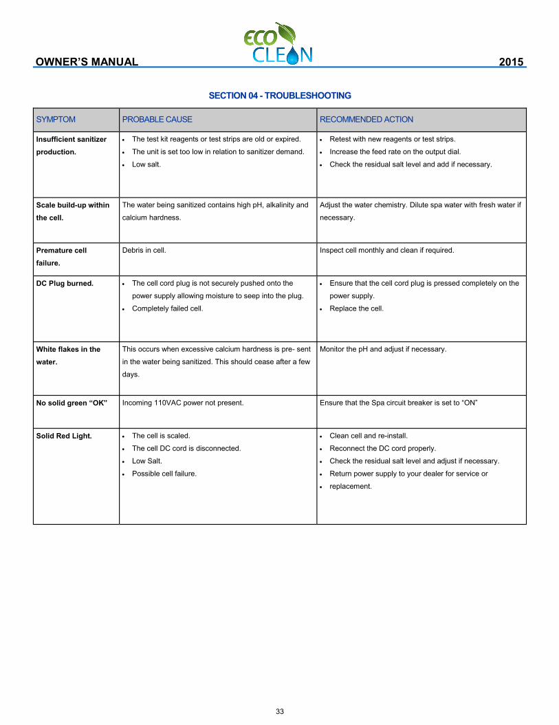
33
OWNER’S MANUAL 2015
SYMPTOM PROBABLE CAUSE RECOMMENDED ACTION
Insufficient sanitizer
production.
The test kit reagents or test strips are old or expired.
The unit is set too low in relation to sanitizer demand.
Low salt.
Retest with new reagents or test strips.
Increase the feed rate on the output dial.
Check the residual salt level and add if necessary.
Scale build-up within
the cell.
The water being sanitized contains high pH, alkalinity and
calcium hardness.
Adjust the water chemistry. Dilute spa water with fresh water if
necessary.
Premature cell
failure.
Debris in cell. Inspect cell monthly and clean if required.
DC Plug burned. The cell cord plug is not securely pushed onto the
power supply allowing moisture to seep into the plug.
Completely failed cell.
Ensure that the cell cord plug is pressed completely on the
power supply.
Replace the cell.
White flakes in the
water.
This occurs when excessive calcium hardness is pre- sent
in the water being sanitized. This should cease after a few
days.
Monitor the pH and adjust if necessary.
No solid green “OK” Incoming 110VAC power not present. Ensure that the Spa circuit breaker is set to “ON”
Solid Red Light. The cell is scaled.
The cell DC cord is disconnected.
Low Salt.
Possible cell failure.
Clean cell and re-install.
Reconnect the DC cord properly.
Check the residual salt level and adjust if necessary.
Return power supply to your dealer for service or
replacement.
SECTION 04 - TROUBLESHOOTING