Embed Size (px)
Citation preview

VerSatilE plug-and-play platform enabling remote pREdictive
mainteNAnce
Grant Agreement No : 767561
Project Acronym : SERENA
Project Start Date : 1st October 2017
Consortium : COMAU S.p.A.
Finn-Power Oyj
VDL Weweler BV
WHIRLPOOL EMEA SpA
Kone Industrial Ltd
Engineering Ingegneria Informatica S.p.A.
OCULAVIS GmbH
SynArea Consultants S.r.l.
DELL EMC
Laboratory for Manufacturing Systems & Automation
Fraunhofer Gesellschaft zur Förderung der angewandten Forschung
VTT Technical Research Centre of Finland Ltd
TRIMEK S.A.
Politecnico Di Torino
Title : Design of cloud-based platform for remote diagnostics Reference : D5.1
Dissemination Level : PU (public)
Date : 2018-09-30
Author/s : ENG/DELL EMC/IPT/COMAU/SYNAREA
Circulation : EU/Consortium
Summary:
The design of the SERENA cloud-based platform for remote diagnostics will be presented in this document to drive the work in all the implementation tasks of WP5, but in strict collaboration with the
parallel work in WP2-3-4 to be validated in WP6, following the requirements defined in WP1.

D5.1 SERENA cloud-based platform for remote diagnostics
2018-09-28 Public 2 (42)
Contents
List of Abbreviations ..........................................................................................................................3
List of Figures ....................................................................................................................................4
Executive Summary ..........................................................................................................................5
1. Introduction ...............................................................................................................................7 1.1 Motivation ........................................................................................................................7 1.2 Work package objectives .................................................................................................7 1.3 Requirements ................................................................................................................. 10
2. SERENA Cloud Platform design ............................................................................................ 11 2.1 Concept .......................................................................................................................... 11 2.2 SERENA Cloud Platform .............................................................................................. 11 2.3 SERENA Infrastructure ................................................................................................ 13
2.3.1 SERENA Auxiliary Services ............................................................................... 14 2.3.2 SERENA Containerisation .................................................................................. 14 2.3.3 Container Management........................................................................................ 15 2.3.4 Exposing Container Resources ............................................................................ 15 2.3.5 Docker Image Development ................................................................................ 16
2.4 Container Orchestration Sub-system ............................................................................ 17 2.4.1 Container Services............................................................................................... 17 2.4.2 Container Management Policies .......................................................................... 19 2.4.3 Docker API Plugins ............................................................................................. 19
2.5 Ingestion Sub-system ..................................................................................................... 20 2.6 Repository Sub-system .................................................................................................. 21 2.7 Processing Sub-system ................................................................................................... 21 2.8 Plug-n-Store Sub-system ............................................................................................... 22 2.9 Internal communications ............................................................................................... 22 2.10 Hardware architecture .................................................................................................. 22
2.10.1 Development Infrastructure ................................................................................. 22 2.10.2 Pilot Infrastructure............................................................................................... 23
3. System interfaces ..................................................................................................................... 24 3.1 Human – machine interfaces ......................................................................................... 24
3.1.1 3D viewer ........................................................................................................... 24 3.2 External interfaces ......................................................................................................... 25
4. Integrity controls ..................................................................................................................... 26
5. Operational scenario ............................................................................................................... 27
6. Conclusion ............................................................................................................................... 28
References ....................................................................................................................................... 29
Annex A – Requirements extract from D1.1 .................................................................................. 30

D5.1 SERENA cloud-based platform for remote diagnostics
2018-09-28 Public 3 (42)
List of Abbreviations
AI Artificial Intelligence
AR Augmented Reality
CAD Computer-Aided Design CEN European Committee for Standardisation
CSP Cloud Service Provide
CWA CEN Workshop Agreement DNS-SD DNS Service Discovery
ERP Enterprise Resource Planning
HDFS Hadoop Distributed File System
HMI Human Machine Interface HTTP HyperText Transfer Protocol
ICT Information and Communications Technology
JEE Java Platform, Enterprise Edition JSON-LD JavaScript Object Notation for Linked Data
KPI Key Performance Indicator
NTP Network Time Protocol ODBC Open DataBase Connectivity
OEM Original Equipment Manufacturer
PLC Programmable Logic Controller
RDF Resource Description Framework REST Representational State Transfer
SaaS Software as a Service
SME Small and Medium Sized Enterprise SPARQL SPARQL Protocol and RDF Query Language
SQL Structured Query Language
STEP STandard for the Exchange of Product model data
ToC Table of Contents TRL Technology Readiness Level
UUID Universally Unique IDentifier
VR Virtual Reality
D5.1 SERENA cloud-based platform for remote diagnostics
2018-09-28 Public 4 (42)
List of Figures
Figure 1 D5.1 and contributing tasks ...................................................................................................5 Figure 2 WP5: tasks and deliverables ..................................................................................................8 Figure 3 Relationship with other tasks .................................................................................................9 Figure 4 Role and goals in maintenance scenario .................................................................................9 Figure 5 SERENA Logical Architecture ............................................................................................ 11 Figure 6 Container Port Mapping ...................................................................................................... 15 Figure 7 Docker Development Environment...................................................................................... 16 Figure 8 Docker Forwarding Service Request ................................................................................... 18 Figure 9 Portainer Orchestration UI .................................................................................................. 19 Figure 10 Main information flow related to the SERENA Cloud Platform ......................................... 22 Figure 11 SERENA 3D viewer web-based visualization .................................................................... 25

D5.1 SERENA cloud-based platform for remote diagnostics
2018-09-28 Public 5 (42)
Executive Summary
The purpose of this document is describing the design of WP5 developments. The current deliverable (i.e. D5.1 – Design of cloud-based platform for remote diagnostics) aims to report on the actual results
of several tasks, namely (see Figure 1):
• T5.1 Communications and Data Processing Architecture design for remote diagnostics which starts
at M7 and ends at M12
• T5.2 Plug-and-play platform for data management and storage
• T5.3 Multi-level data processing & correlation
• T5.4 Data confidentiality and security middleware
• T5.5 Implementation of Advanced HMIs for data presentation which start at M9 and end at M24
The user’s requirements collected in WP1 for the cloud-based platform for remote diagnostics will be
used for defining the SERENA cloud-based solutions for predictive maintenance but considering also the requirements related to the remote factory condition monitoring, AI condition-based maintenance
and planning and AR based tools for remote assistance and operator support. The overreaching solution
will be able to support predictive diagnostics and data analytics in a remote cloud and proposing
corrective actions and guidance for maintenance activities within the factory.
To this end the main input of such activities is D1.1 – Report on Use-case definition, evaluation metrics and End-Users requirements, another project deliverable integrating and reporting the outcomes of all
tasks in WP1 whose objectives are: a comprehensive description of the targeted use-cases from the end-
users (WHEMEA, KONE, TRIMEK, VDLWEW); extract user requirements and evaluation criteria in
terms of performance, usability and relevant KPIs; define the roadmap towards achieving industrial TRL for each targeted technology; have a precise description of the end users requirements in terms of remote
factory condition monitoring, AI condition based maintenance and planning, AR based tools for remote
assistance and operator support, cloud-based platform for remote diagnostics.
Moreover, D5.1 has been written taking in consideration the approaches followed in the following
deliverables due at M12 as well:
• D2.1 - Design of versatile framework for factory condition monitoring: this deliverable describes
the design of HW and SW solutions for versatile remote factory monitoring;
• D3.1 - Design of versatile maintenance and planning: this deliverable describes the design of WP3 approach in terms of improving existing solutions for predictive maintenance as well as planning of
maintenance solutions;
• D4.1 - Design of AR-based remote diagnostics platform and interfaces: this deliverable describes
the design of WP4 overall approach in terms of development and adaptation of Augmented Reality
(AR) based technologies for providing step-by-step assistance to the maintenance technicians and sensor-based information about the status of the machinery and overall equipment within the
factory;
• D6.1 - Test beds design & adaption: this deliverable focuses on the design and integration of the
test beds regarding the white goods, metrological engineering, and elevators production industrial
Figure 1 D5.1 and contributing tasks
D5.1 SERENA cloud-based platform for remote diagnostics
2018-09-28 Public 6 (42)
pilot cases (WHEMEA, TRIMEK and KONE), as well as the pre-demonstration case of steel parts
production industry (VDLWEW). To this aim, the SERENA architecture will be tailored to allow
use case owners to implement their testbeds in accordance with their specific requirements and
constraints.
The methodology followed to complete deliverable D5.1 included:
• Table of Contents (ToC) and document scope: once the ToC was agreed among the partners, a
detailed template including a description of the required information along with examples was
circulated to guide the section coordinators in the collection of the required information from all the contributing partners.
• Theoretic background/principles and existing frameworks, solutions, references, technologies
analysis and alignment to the project objectives.
• Follow up activities to monitor the work progress through principally two types of meeting: (1) Bi-
weekly task leaders conference meetings specifically dealing with WP5-related activities; (2) Monthly conference meetings with all the work-package leaders focused on SERENA overreaching
solutions specification and development.

D5.1 SERENA cloud-based platform for remote diagnostics
2018-09-28 Public 7 (42)
1. Introduction
1.1 Motivation
Aim of WP5 is defining the cloud-based platform for versatile remote diagnostics enabling predictive
diagnostics, by managing the data remotely, applying data analytics and predictive maintenance algorithms in a remote cloud and proposing corrective actions and guidance for maintenance in near real
time and in the correct place within the factory.
The challenges faced by the different cloud implementations vary, therefore the requirements
defined for the SERENA cloud-based system must encompass the combined set of all requirements, enabling several deployment approaches (e.g. private cloud, public cloud, or on-premises). To this end,
the SERENA system should provide a layer of abstraction, which, to the extent possible, obscures the
system from the underlying implementation. One characteristic that most cloud-based systems have in common is that they are based on a
distributed architecture (e.g. defining a microservices architecture), consisting of several independent
services providing the application functions. Such an architecture has several advantages over previous monolithic or bespoke component architectures: a) they are more responsive to the demands of the high-
variable of modern businesses; b) they are more scalable, as predefined templates can be instantiated
quickly to meet increasing production demands; and c) it is easier to swap out one component for
another, provided it conforms to the same API and behaviour. The last point is particularly relevant for the SERENA project as it facilitates a plug-and-play architecture, which is one of SERENA’s core
objectives.
Microservices architecture typically implement the different services in one, or a set, of container(s) in a virtualised environment, this gives the system the flexibility to instantiate preconfigured
services from container templates and move containers around the physical IT infrastructure to optimise
its performance. As most major CSP provide their tenant environments as a microservices architecture, and many private clouds are implemented in the same way, basing the SERENA system on a
microservices architecture gives the manufacturing company the flexibility to implement their solution
in either environment, or a hybrid of the two. It also means that the SERENA system can inherit the
added benefits of a microservices architecture, as outlined in the previous paragraphs. Whilst each CSP implements their environment in a proprietary way, the industry is starting to converge on a set of
common architectural patters, and support for common services; by exploiting this convergence, the
SERENA system can be made highly flexible in how and where it is deployed.
1.2 Work package objectives
WP5 aims to design a cloud-based platform for remote diagnostics, providing specifications for the
networking infrastructure, the cloud computing infrastructure, the data processing components, the digital models, and the shared situation awareness components and to instantiate the remote SERENA
Cloud Platform for piloting purposes in the different industrial sectors.
To reach this objective, WP5 has been decomposed in 6 tasks (see Figure 2):
1. Task 5.1 Communications and Data Processing Architecture design for remote diagnostics.
This task is responsible for specifying the communication and data processing components, from
the shop-floor to the cloud and back and the designing new communication capabilities (green- and brown- field integration). The main results are the specification of an industrial networking
infrastructure supporting both edge and cloud components and the selection of a service
infrastructure (e.g. based on existing open source solutions). 2. Task 5.2 Plug-and-play platform for data management and storage.
This task is responsible for developing techniques and tools for sensing context data and defining
semantic techniques for aggregation and fusion and developing and deploying new integrated data-lifecycle management approach. The main results will be the Integrated process execution
sensing service, the Cloud Storage Service supporting the Plug-and-Store paradigm and data

D5.1 SERENA cloud-based platform for remote diagnostics
2018-09-28 Public 8 (42)
aggregation capabilities and the Real-time communication using self-descriptive communication
protocol.
3. Task 5.3 Multi-level data processing & correlation
This task is responsible for developing new techniques for real-time processing, analysing, and interpreting and enabling the execution of machine learning and data analytics tasks. The main
results will be an infrastructure for distributed data analytics over the edge/cloud nodes.
4. Task 5.4 Data confidentiality and security middleware
This task is responsible for defining the data protection approach, analysing existing standards and
available open source solutions, and providing built-in functionalities using a multi-layer Security-
by-Design approach. The main results will be the principles and the guidelines to drive the trustworthiness of the SERENA architecture and the development of a Secure Middleware for
distributed architecture.
5. Task 5.5 Implementation of Advanced HMIs for data presentation
This task is responsible for developing techniques and tools to support the visual representation of
the sensed and fused context data and for using multi-modal interaction technologies. The main
results will be the Visualization-as-a-Service capabilities and a set of web services to configure
the visual features of the HMI (e.g. from AR tools developed in WP4) 6. Task 5.6 Cloud-based platform prototype
This task is responsible for integrating the components of the previous tasks into a prototype,
supporting the deployment on several possible technology platforms and support an easy and
seamless integration with commercial SW (maintenance and production). The main results will be SERENA Cloud Platform prototype.
Based on the requirements of WP1, the project will focus on developing the prototypes in terms of a) definition of the service-oriented architecture for remote control (WP2), b) Al condition-based
maintenance and planning techniques (WP3), c) AR-based technologies for remote assistance and
human operator support (WP4) and d) Cloud-based platform for versatile remote diagnostics (WP5) (see Figure 3).
Figure 2 WP5: tasks and deliverables

D5.1 SERENA cloud-based platform for remote diagnostics
2018-09-28 Public 9 (42)
These development activities will be the first step of an iterative process which will lead to the first
prototype of WP5 developments in M24 and the final prototype in M30.
The main goals of the predictive maintenance are:
• avoid an unpredicted fault and predict when it could occur;
• avoid unnecessary machineries/equipment replacement, if they are still able to work well enough;
• providing valuable information to the maintenance director, who needs to evaluate risks and benefits that comes from a predictive scenario;
• produce cost savings over preventive maintenance, allowing a convenient scheduling of the
maintenance operations.
These goals are pursued by the SERENA project, working with production data that comes from the field (from the IoT platform) and getting additional information from the operational systems (e.g.
master data, ERP, etc.) used by the customer to manage the whole maintenance process and to provide
direct feedbacks for received early warnings, with eventual related interventions (see Figure 4). Using this additional information, the SERENA Cloud Platform can measure impact over costs and
operations, fully supporting the decisional process concerning the maintenance plan.
To achieve the listed goals data are collected from the field and loaded into a data lake (on-premise or
on-cloud) at the end of every working cycle. Here, advanced algorithms based on machine learning
Figure 3 Relationship with other tasks
Figure 4 Role and goals in maintenance scenario

D5.1 SERENA cloud-based platform for remote diagnostics
2018-09-28 Public 10 (42)
techniques learn what is the standard behaviour of every machinery/equipment, predict what will be the
expected one in the future, evaluating if that could be anomalous or not.
1.3 Requirements
The main requirements for the technical developments of WP2-5 and for the basis of the testbed design
in WP6 have been defined in the scope of WP1. Specifically, these comprehend:
• an analysis of the status and requirements of the different pilot cases, including the equipment to be
considered within the project, the maintenance needs, the expectations from the project;
• The identified requirements of the technical systems to be developed based on the needs identified in pilot cases analysis, focusing on the following aspects:
o Remote factory condition monitoring and control
o AI condition-based maintenance and planning techniques
o AR-based technologies for remote assistance and human operator support o Cloud-based platform for versatile remote diagnostics
Focusing on WP5 - Cloud-based platform for versatile remote diagnostics, the main functional and non-functional requirements of the Cloud-based platform have been grouped in several families, covering
the differne sub-sytems foreseen un WP5. The main logical functions has been decomponsed in
ingestion, storage, processing, management (for further details on the identified requirements under the scope of WP1 please check Annex A).
D5.1 SERENA cloud-based platform for remote diagnostics
2018-09-28 Public 11 (42)
2. SERENA Cloud Platform design
2.1 Concept
Designing the SERENA Cloud Platform, the following functions will be provided:
• Communications and Data Processing Architecture design for remote diagnostics
o Specification of an industrial networking infrastructure supporting both edge and cloud components
o Selection of a service infrastructure able to provide new communication capabilities
• Plug-and-play platform for data management and storage
o Integrated process execution sensing service
o Cloud Storage Service supporting the Plug-and-Store paradigm and data aggregation capabilities
o Real-time communication using self-descriptive communication protocol
• Multi-level data processing & correlation
o Infrastructure for distributed data analytics over the edge/cloud nodes
• Data confidentiality and security middleware o Principles and guidelines to drive the trustworthiness of the SERENA architecture
o Secure Middleware for distributed architecture
• Advanced HMIs for data presentation
o Visualization-as-a-Service capabilities
• Set of web services to configure the visual features of the HMI
2.2 SERENA Cloud Platform
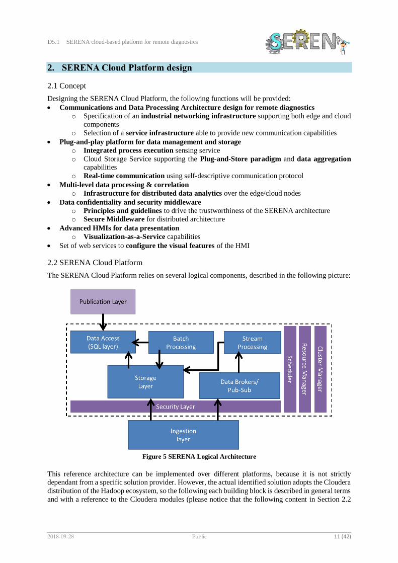
The SERENA Cloud Platform relies on several logical components, described in the following picture:
This reference architecture can be implemented over different platforms, because it is not strictly dependant from a specific solution provider. However, the actual identified solution adopts the Cloudera
distribution of the Hadoop ecosystem, so the following each building block is described in general terms
and with a reference to the Cloudera modules (please notice that the following content in Section 2.2
Figure 5 SERENA Logical Architecture

D5.1 SERENA cloud-based platform for remote diagnostics
2018-09-28 Public 12 (42)
has already been described with D1.1, and it is replicated here for providing a coherent description of
the designed solution).
Ingestion Layer
This layer deals with the task of collecting data from several sources, performing some pre-processing
workflow, and saving them in the Data Lake. The data ingestion can gather data in real time fashion as
well as in batch, depending on the source and on the use-case. For the current purposes, the ingestion is scheduled and gets data from FTP directories where files collected from the plant are available on daily
basis. The aim of this component is to enable the transmission of files from the inside of the data lake
to the outside (as happens with the model built on the big data platform that is made available to the early warning module in-plant). The tool chosen to accomplish all the above features is Apache Nifi.
Storage Layer
The storage layer is responsible for the persistence of raw data collected by the ingestion process and data which is the result of the distributed processes and analysis within the data lake. There are different
storages that can be used since supported by each Hadoop distribution: distributed file system or NoSQL
database. For the SERENA project, both HDFS and MySQL are used, depending on the data pipeline to build. HDFS stores incoming data from the ingestion process and the datasets computed by the
algorithms, while MySQL holds metadata.
Information brokers/pub-sub
To satisfy real-time purposes, a publish-subscribe distributed message queue is available within the data
lake platform, even if not configured yet. The role of this component is to stock data from streaming
ingestion processes to feed the streaming layer of computations described below.
Stream Processing layer
Although not fully designed, streaming pipelines can be developed by using Spark Streaming libraries. It allows data to be filtered, processed, aggregated, and analysed event by event so that real-time results
are available.
Publication Layer
In the reference architecture, this layer shows the results of the predictive maintenance algorithms run
on a huge amount of data collected from the field by the batch processes described above. As default
SERENA will provide a prebuilt set of analysis, but some other analysis can be added using any other analytics tools and libraries.
Batch Processing Layer
Once data is landed on the data lake it is processed by the distributed framework Spark, capable of
managing huge amounts of data, dealing with cleaning tasks as well as analysis through custom
algorithms for predictive maintenance objective. The batch jobs are scheduled and executed evenly
across the cluster every day.
Data Access Layer
To access files stored in the data lake, because of the advanced analytics run by the batch processing layer in Spark, a SQL layer is configured. This tool acts as a gateway for applications that need to publish
information generated in the data lake through a front-end UI, as well as perform some additional query
on Hadoop, benefiting from the parallel computation that can be run on the platform. Impala is the
chosen tool that allows the publication layer to perform insights on the data lake.
Security Layer
The Security layer involves authentication, authorization, encryption, and data lineage features, and strongly depends on the chose Hadoop distribution: SERENA is enabled to use Kerberos protocol to
connect to Active Directory or LDAP authentication user domains. On HDFS privileges can be

D5.1 SERENA cloud-based platform for remote diagnostics
2018-09-28 Public 13 (42)
configured using ACLs policies, while It is also possible to set proper permissions on Impala tables
through Apache Sentry (embedded in the solution). To perform data lineage and leverage encryption at-
rest policies Cloudera Navigator can be used, subscribing Cloudera Enterprise Data Hub license.
Scheduler
This layer addresses the scheduling of batch jobs and orchestrates them through a proper workflow of
different actions. Within the current scenario, this task is dealt by Oozie.
Resource manager
Hadoop allows distributed jobs to be executed in the cluster, where data is hosted. Different jobs are run on the available nodes in the platform, considering the resources in terms of RAM and CPU and the data
locality of the partitions of the files to be processed. All these tasks are managed and scheduled by
YARN, which is the resource negotiator of Hadoop.
Cluster Manager
Every Hadoop distribution offers a tool to manage the cluster, in terms of hosts and services. Cloudera
Manager is a web application, made for Hadoop Administrator to let them master the platform.
2.3 SERENA Infrastructure
As defined in section 2.2, the SERENA system is comprised of several logical components, which
collectively provide SERENA’s predictive maintenance functionality. These logical components reside in the SERENA cloud, but the functionality extends to the edge gateways and sensors on the factory
floor. It also encompasses other SERENA functionality including a) adaptive maintenance scheduling,
driven from the prediction results; b) augmented reality to assist operators and technical staff maintaining the factory equipment; c) equipment visual simulation applications; and d) other incumbent
factory management system. Additionally, the SERENA system is intended to be flexible enough to be
hosted on an on-premises environment, a CSP environment, or a hybrid of the two, as outlined in Section
1. To meet these varying requirements, the SERENA system will be designed on a micro-services architecture pattern [1], where each logical component is a service within the SERENA system.
Each service within the SERENA system communicates and collaborates with other services to
perform its specific function, and extends to other components, such as the edge gateways. The principal communications protocol is based on HTTP REST, but other protocols can be supported as required.
Whilst REST is a text-based protocol, and therefore not as efficient as some binary protocols, its wide
spread support, both inside the manufacturing industry, and beyond, make it an ideal candidate for SERENA. In a micro-services architecture each service can communicate with a set of other services,
to perform its function. Therefore, the SERENA infrastructure will implement functionality to facilitate
this inter-service communication in a reliable and secure way.
The SERENA system must also support several non-functional requirements including a) flexibility; b) scalability; c) reliability; and d) security. As previously discussed, the SERENA system
must be flexible enough to be hosted on a wide variety of on-premise and CSP environments, but
additionally it should be agnostic to the actual technology used to implement a logical component. Whilst the SERENA reference architecture is largely based on the Cloudera technology stack, the
reference architecture defines a logical set of the API and behaviour for each service. Therefore, the
actual technology implementation of a service, can be swapped for any other suitable technology, provided it conforms to the logical component’s API and behaviour. For example, the reference
architecture implements the ingest service using Apache’s NiFi1 data flow engine, but this service could
be replaced with an equivalent one based on Apache Camel2; it is the logical component’s function
within the SERENA system that is important, not its technical implementation. This implementation transparency is an important concept in SERENA’s plug-n-play functionality.
1 https://nifi.apache.org/ 2 http://camel.apache.org/

D5.1 SERENA cloud-based platform for remote diagnostics
2018-09-28 Public 14 (42)
2.3.1 SERENA Auxiliary Services
In addition to SERENA’s main functional services, there are several auxiliary services, which contribute
to the overall operation of the system, such as DNS-SD and NTP services. The Domain Name System
Service Discovery service is used by subsystems to discover service they need to perform their function and resolve their domain names into IP addresses. This functionality decouples the logical component
providing the service, from the location of the service denoted by its static IP address. SERENA provides
additional features to abstract services from their implementations, which will be described later. The Network Time Protocol (NTP) service helps maintain a synchronised system wide time across all
SERENA services and edge gateways. When collecting sensor data from multiple IoT sources, it is
important that the distributed subsystems all share the same system time, so that timestamped data can be accurately correlated with events.
2.3.2 SERENA Containerisation
The principal infrastructure technology to implement SERENA’s services is Docker containers [2].
Docker provides an open source implementation of a process containerization system, which encapsulates the service, and abstracts it from the underlying infrastructure that hosts the containers.
Unlike virtual machines, which are a mechanism for logically dividing physical machines, Docker
containers are principally a mechanism to wrap an application, and the resources required to run it, into a simple executable unit. Therefore, Docket containers are isolated from the underlying host
infrastructure, and can easily be distributed between the available hosts to improve the flexibility and
agility of the system. Docker containers share many similar features to virtual machines, but, as
explained, they perform distinctly different function within the infrastructure system. In fact, virtual machines and containers can be complimentary technologies, and used in conjunction with each other,
the containers being layered on top of the virtual machines. One of the goals of the SERENA project, is
for the SERENA system to have the flexibility to run on a wide variety of host infrastructures, from physical servers or virtual machines, to on-premises clouds and CSP hosted environments, Docker
containers provide the mechanism to achieve this goal.
As well as being used to implement the SERENA cloud services, the same Docker containerization technology is used, to encapsulate and abstract, processes on the edge gateway devices, SERENA edge
services. This abstracts the SERENA edge services, distributed around the factory floor, from the
underlying gateway operating system and hardware that host them. Again, this achieves another of
SERENA’s goals, i.e. to give the implementer of the SERENA system the maximum flexibility in how it is deployed. Using the same containerisation technology in both the SERENA cloud and on the
SERENA edge gateways, means that the SERENA system, has a unified architecture, which operates
and can be managed. It also facilitates the migration of services, in the form of Docker containers, from the SERENA cloud to the edge gateways. This allows services to be moved around the SERENA system
to where they are needed, or can be operated most efficiently, rather than being fixed in any one location
in a classic static architecture. Docker containers are instantiated from Docker images, which are like virtual machine templates,
like a blueprint of how do build and run the contained application and the resources it requires. The
container is a wrapper around the instantiated image, that provides a common API to manage the
containers lifecycle, as well as exposing the application contained inside it. Typically, a docker image consists of a single application, which conforms to the micro-services architecture pattern. If several
applications are required, to perform a specific piece of system functionality, such as a JEE server and
its web server proxy, the discrete applications are implemented as separate images, and instantiated as a stack of individual containers linked together to perform their function.
Docker containers are instantiated and run on the Docker execution engine, which must be installed
on each platform that hosts Docker containers. The execution engine is like the hypervisor used to run
virtual machines. There is no conflict if the Docker containers are run on top of virtualised host infrastructure; in this case the virtualised host infrastructure hosts virtual machines, and the virtual
machines host the Docket execution engine, with both abstraction layers providing different, but
complimentary, functionality to the overall system. The execution engine, and its associated tools,

D5.1 SERENA cloud-based platform for remote diagnostics
2018-09-28 Public 15 (42)
manage the lifecycle of the containers running on the host, they also manage the images and how they
are downloaded and/or built.
2.3.3 Container Management
Docker images reside in a Docker image registry. Each Docker execution engine has its own local registry, which hold images downloaded or locally built. There is a common Internet registry called
Docker Hub [3], which holds open source images create and uploaded by third parties. When an image
is instantiated into a container by the local Docker execution engine, it first tries to find the image in its local registry. If the image is not found locally, it is downloaded from a remote registry; the default
registry is Docker Hub. Whilst this works for certain Docker implementations, it is based on some
assumptions that a) the SERENA system would always have access to the Internet; b) the images correctly implement the required functionality; c) the image configuration exposes the containers
network and storage in a way that conforms to SERENA’s reference architecture; and d) the images do
not contain malicious code [4]. To mitigate the risks of an Internet based registry, the SERENA system
implements its own system wide local registry. This does not preclude images being downloaded from the Internet but means the process can be performed in a controlled manner, with the images always
being available from the local system registry. For resilience and security, SERENA production Docker
execution engine should not download their images from the Internet, but instead default to the local system registry. An additional advantage of using a local system registry, is that it is possible to ensure,
through comparing image digests, that the same SERENA image is being run on each local Docker
execution engine, in the SERENA system, which ensures consistency of behaviour across the system
services.
2.3.4 Exposing Container Resources
The server that hosts the Docker execution engine shares a private internal network, that was created as
part of the Docker installation process. By default, the application within the Docker container can access the host’s external network, but the container does not expose any network ports, therefore the
application cannot be accessed by any external entity. It is often necessary to expose an applications
network ports to make it is features accessible, such as a database’s ODBC port or an applications management graphical user interface. Docker containers can be configured to expose a port when they
are instantiated, and the port is mapped to an available host port. Thus, the application running inside
the container can be accessed from the hosts IP address and the mapped port. The internal application
port does not need to be mapped to the same port number on the host, e.g. the application may provide an HTTP interface on port 80, but this can be mapped to the host’s port 8090, see Figure 6.
This feature avoids conflicts with existing ports used by the host, but for the SERENA system it has an
added benefit; some applications, such as node-red, use a standard port, 1880, to expose input nodes in their workflows. If multiple containers were running the same application image, on the same host, they
would have the same internal port numbers, and a port conflict would occur. Instead each container
instance can be configured to map to a different host port. So, in the node-red example, the internal
Figure 6 Container Port Mapping

D5.1 SERENA cloud-based platform for remote diagnostics
2018-09-28 Public 16 (42)
node-red port, 1880, could be mapped to port 9880 for the first container, 9881 for the second container,
and so on; thus, multiple discrete node-red instances, could be run on the same host, without causing a
host port conflict.
By default, Docker containers are supposed to be stateless, that is they do not modify any application data internally. This is very powerful as it means that each container running the same image,
are effectively clones. So, if a container dies, it can be replaced with another container running the same
image. Likewise, if the system requires more capacity, additional contains can be started, sharing the workload between them. For example, multiple web proxy server can be started, and the Internet traffic
balanced between them. However, many applications modify state, e.g. a database server continually
alters its data and log files based on the SQL operations being performed. It is possible to store the state of an application by modifying the container’s internal files, but in most cases, this is not desirable as it
means that the containers are no-longer clones of each other. Instead Docker images can externalise
their state by storing specific application directories outside of the container. How and where these
directories are externalised is controlled by the Docker execution engine.
2.3.5 Docker Image Development
Whilst Docker images can be downloaded from a remote trusted source, they will typically need to be
modified to conform to the SERENA architecture or to meet specific manufacturing process requirements. Alternatively, the images can be built locally from scratch. Either way there are two
methods to build of modify images a) defining the configuration of the image in a Docker file, along
with the configuration resources to build the image; and b) to instantiate an image in a container, then
modify the application running in the container and saving the container back as an image. Whilst the former image build/modification method is the more usual, the later method has advantages in certain
scenarios; the SERENA system will utilize both methods.
Figure 7 illustrates the concept of the SERENA Docker development environment, which consists of
the Docker development host, the Docker production hosts, and the SERENA system registry. Docker images are built and tested on the development host, which is a sandboxed environment isolated from
the production Docker hosts. More than one development host can be implemented to facilitate parallel
development, or where complex inter host connectivity needs to be tested. The images can be downloaded from an Internet registry or created locally from scratch. As the development environment
is fully sandboxed, images downloaded from the Internet can be fully verified and scanned for malicious
code without exposing the production environment to potential risks. Once the images have been fully
Figure 7 Docker Development Environment

D5.1 SERENA cloud-based platform for remote diagnostics
2018-09-28 Public 17 (42)
tested on the development environment, they are uploaded to the SERENA system registry, from where
they can be rolled out to the required production hosts.
Typically, images for specific SERENA services would be built using a Docker file to define their
construction and the required libraries, executables, and other resource; or downloaded from the Internet and modified to run on the SERENA system. Each service image is given a name consisting of the
SERENA repository where it can be downloaded from, the name of the service it contains, and a
sequential version number. The version number consists of three standard parts, the major release, the minor release, and the patch number. As an image is updated, its version number is incremented
appropriately.
It is sometimes difficult to modify an applications behaviour by changing the Docker file, as the changes are embedded within the application and cannot be easily altered by command-line entries. In
these cases, a different image modification approach is taken. The image is instantiated into a running
Docker container on the development environment. Here the running application can be modified to
meet the new requirements of the system. Once the desired modification has been made and tested, the container is saved as a new Docker image, with an incremented version number. The updated image can
then be rolled out into production in the manner previously described. For example, a node-red process
flow service, designed to handle sensor data from a specific piece of factory machinery, must be modified to collect additional sensor data. Node-red uses a graphical user interface, so its flows can be
difficult to update from the command-line, especially if new specialized nodes need to be installed for
the flow. Instead the node-red flow engine, the specialised nodes and the specific flow required to
process the machineries sensor data, are packages as a homogenous Docket image. If the flow needs to be modified, the existing image is run in a container, modified via the graphical user interface, and saved
as a new image. This technique should be avoided if possible, as it involves altering the internal state of
the image but is the simplest approach in certain instances.
2.4 Container Orchestration Sub-system
Simple Docker environments, used for development and testing, can be managed manually using
individual Docker commands; effectively, each Docker execution engine is managed individually. For large production environments a more holistic and automated approach is needed, which can be achieved
using a container orchestrator. There are several excellent open source container orchestrators available,
two of the main ones are Kubernetes [5] and Docker Swarm [6], but there are a number of open source and commercial container orchestrators available. The SERENA reference architecture uses Docker
Swarm, but many of the alternatives have similar features, and in theory it should be possible to swap
Docker Swarm for one of the others, such as Kubernetes. Docker Swarm is bundled with the Docker execution engine and is a distributed peer-to-peer
container management infrastructure. Docker execution engines can join a Docker Swarm as either a
manager or a worker. Managers connectively control the Docker Swarm, and both managers and
workers can run containers as part of the swarm. It is important to understand that Docker Swarm is a peer-to-peer system, so the swarm can be controlled by any manager in the swarm, but apart from the
management functionality, every Docker execution engine in the swarm has the same status, and there
is no central point of control, the swarm is managed collectively. In SERENA’s case the swarm extends out from the SERENA cloud to the SERENA edge, forming a homogeneous container environment all
the way to the factory floor.
Docker Swarm has a few features that help to fulfil SERENA’s functional and non-functional requirements, these include a) the concept of resilient cluster services, which are location independent;
b) container runtime policies, and a robust security framework; and c) the ability to extend Docker’s
functionality using plug-in APIs.
2.4.1 Container Services
Central to the concept of a Docker Swarm is the service. A Docker service is image that performs a
specific function for a system, such as web proxy server. The swarm instantiates one of more images as
containers, whose lifecycle are directly managed by the swarm; each running container is called a task.

D5.1 SERENA cloud-based platform for remote diagnostics
2018-09-28 Public 18 (42)
The swarm creates the specified number of tasks, and distributes them between the available hosts, based
on user defined policies, which will be discussed later in the section. If one of the tasks fails, it will be
restarted by the swarm, and if a host fails its hosted tasks will be redistributed to other hosts in the
swarm. Ideally the service images should be stateless, and the tasks are clones of one another, which allows them to be restarted in another location, without impacting the overall operation of the service.
In case an instantiated container fails, the local Docker execution engine takes no further action,
and the application is not available. Creating a service consisting of a single task, has the advantage that if it fails, the swarm will restart another clone of the image, either running on the same host or a different
on. Therefore, there is an advantage in instantiating an image as a service, even if it only has one task,
as the swarm will automatically maintain the required number of instances making the service always available; and fulfilling one of SERENA’s main non-functional requirements – component resilience.
Although a Docker service is made up of individual tasks, Docker containers are under the control
of the swarm, they effectively operate as a single entity. As previously mention, if a task in a cluster
fails, another one will be created to replace it; but the swarm can also dynamically increase or decrease the number of tasks in a service, so if the workload increases the user can modify the number of instances
in the service, and the swarm will automatically start new tasks to comply with the updated policy. The
swarm instructs each host running a task to download and run a specific image from the Docker registry. As the SERENA image registry resides in the swarm, as a service, and all SERENA’s cloud production
infrastructure hosts and edge gateways are part of the swarm, the swarm can instantiate any SERENA
image from the dedicated SERENA system registry, which ensures that all hosts are running the same
version of the image. By default, all tasks in a cluster share a common cluster port number, and the swarm load-balances incoming traffic between the tasks in the service, therefore a service is collectively
defined by its port number. If a node in the swarm receives network message for a given service, denoted
by its service port, and it is not hosting one of the tasks in a service, the node forwards the message to another node in the swarm that is hosting one of the tasks in the service, see Figure 8. SERENA concept
of a service maps directly to Docker Swarm’s implementation of a clustered resilient service and
fulfilling another of SERENA’s main non-functional requirements – system scalability.
One technical challenge for SERENA, is for the node-red flows running on the gateways, to be able to
forward their sensor data to the SERENA ingest service, but how do they know the network address of the service. Hardcoding the IP address into the flow is not a production scalable solution. The SERENA
DNS-SD service will help identify the service, resolve it to its domain name, and then resolve it to its
dynamic IP address. Another implementation strategy would be to use the Docker service port forwarding functionality. The ingest service is hosted, as a cluster, on several servers in the SERENA
cloud infrastructure, which are part of the Docker swarm. If the edge gateway is also part of the Docker
swarm, it does not host an instance of the ingest service, but the local Docker execution engine knows where the task in the services are hosted and will forward any incoming message to one of the tasks. So,
if a node-red flow image running in a container on an edge gateway, sends a message to its own host
using the ingest services common port number, the host should automatically forward the message to
an instance of the ingest service.
Figure 8 Docker Forwarding Service Request

D5.1 SERENA cloud-based platform for remote diagnostics
2018-09-28 Public 19 (42)
2.4.2 Container Management Policies
Docker manages service by means of policies, e.g. policies can be setup to only run tasks on specific
hosts, to run a specific number of tasks in a service cluster, or that every instance of a host with a given
policy label should run a single instance of a specific service. For example, if we have an edge gateway that monitors a given piece of machinery, it needs to host a specific node-red flow image to process the
sensor data from that machinery; by defining a Docker policy label on the gateway, which identifies the
required image, Docker swarm will ensure that the require image is downloaded and run on the gateway. As any number of policies can be defined for a swarm host. All Docker images that need to run on a
specific host can by defined and automatically deployed.
Docker Swarm also can perform a staggered rollout for an updated image. For example, if a service image was updated and tested, in the development environment and uploaded to the SERENA system
registry, Docker swarm can be used to perform a staggered rollout of the new version sequentially to
every swarm node hosting a service task. In this way, production service updates can be, automated and
rolled out in a controlled manner. Docker Swarm has a strong security framework based on policies and certificates to authenticate
entities and is like Archers distributed security framework. The intension for SERENA is to extend the
Docker Swarm security framework to meet SERENA’s security requirements.
2.4.3 Docker API Plugins
Docker and Docker Swarm provide an extensive set of APIs and plugins, which allow the functionality
of the container management system to be extended and integrated into the broader SERENA system.
For example, Docker provides basic externalisation of storage volumes, from the Docker containers, but this functionality can be enhanced to implement more sophisticated storage drives, which can implement
virtual storage solutions. SERENA will make use of the storage volume plugin to develop its own plug-
n-store storage driver. Docker and Docker Swarm also provide an extensive and secure management API, which enables third party products to extend and simplify the management of the infrastructure.
Figure 9 Portainer Orchestration UI

D5.1 SERENA cloud-based platform for remote diagnostics
2018-09-28 Public 20 (42)
Portainer [7] is an open source graphical user interface to control the operation and orchestration of the
container environment, and directly plugs into Docker and Docker Swarm’s APIs. Portainer will be used
to manage the underlying infrastructure of the SERENA cloud and the edge gateways. Figure 9 shows
the Portainer graphical user interface, which greatly simplifies the management of the containerized infrastructure. For example, the number of tasks running in a service can be increased simple by going
to the appropriate service and incrementing the spinner control. Portainer is itself implemented as a
resilient service and is one of the auxiliary services implemented by SERENA.
2.5 Ingestion Sub-system
The ingestion service is the connection between the SERENA cloud and the SERENA edge gateways.
It receives sensor data and metadata from the gateways and stores it in the SERENA cloud for subsequent processing by the SERENA analytic service. The ingest service is implemented as a resilient
and saleable cluster of NiFi data process flow engines. Each engine is enclosed in a contained that runs
as a task under the control of the Docker Swarm infrastructure. If a give task fails or the overall service needs to be scaled up to handle increased sensor data from the factory floor, Docker Swarm will start
new instances of the task.
The ingest service exposes a RESTapi endpoint over an SSL connection, which uses the SERENA security service to mutually authenticate the entities and validate that the gateways are authorised to
send data to the service. All the tasks in the service share a common service port number, and incoming
traffic is load balanced between the available tasks in the server. The actual process flow is imbedded
within the engine and wrapped as a single container image running as a Docker task. As the implementation and operation of the data process flow engines are stateless, any task in the service can
handle incoming traffic from any gateway.
The purpose of the ingest server is to receive sensor data and metadata, from the edge gateways, as a single message, and split the data and metadata into two repositories, the data repository service,
and the metadata repository service. It also cross references the data and metadata between the two
repositories. The data repository service is the Cloudera implementation of Hadoop, which provides an
HDFS data store. The metadata repository is a combination of relational database, and a semantic layer on top of it, capable of storing and referencing the metadata via both SQL and SPARQL queries. The
message is received in a canonical JSON-LD format, which is a self-describing message structure that
contains the data and a semantic context for the data. The sensor data can be in a raw data format, as received from the sensor, or smart data format,
which has been pre-processed by the edge gateways to produce an aggregated feature set. The raw sensor
data is typically much larger than the smart data and is only forwarded to the SERENA cloud when deeper analysis is required. The metadata contains data relating to how and where the sensor data was
acquired, as well as information relating to the specific piece of plant being monitored and its operation;
this data provides addition contextual information about the sensor data and is used by the analytics
service to search for relevant data and enrich its analysis. The ingest service extracts the smart data and/or raw sensor data from the incoming message. Both
types of data are converted into sets of comma delimited strings and stored in flat files in the data
repository. Due to the size of the raw sensor data, it is stored in individual files, based on the collection window metadata. Smart data may only consist of a single string, and thus is typically appended to an
existing file, whose collection window is defined in the metadata repository. If a new file is created, it
is given a unique UUID file reference, the file reference of existing files is retrieved from the metadata repository. The ingest service also extracts the metadata from the incoming message and is converted
into an enhanced MIMOSA schema data format and stored in the metadata repository. The metadata
contains information providing context for the sensor data, such as the manufacturing operation being
performed by a robot over the data collection window. The metadata allows the analytics engine to retrieve data based on the specific operation or configuration of the plant. The data file reference is
included in the metadata, so that the SERENA services, or external authorised systems, can retrieve the
required data. Thus, one of the functions of the metadata repository is as a smart index into the HDFS data store.
D5.1 SERENA cloud-based platform for remote diagnostics
2018-09-28 Public 21 (42)
2.6 Repository Sub-system
The data repository service stores the sensor data collected from the factories manufacturing process.
The data is received into the SERENA cloud and stored in the repository as comma delimited flat files, however other filetype can be supported. The service is implemented as a Cloudera cluster running on
top of a Docker Swarm service cluster, so there is a one-to-one implementation mapping between a
Cloudera node and a Docker container. This enables the scalability and resilience of the Docker Swarm infrastructure, combined with the Hadoop advanced functionality of Cloudera.
Sensor data stored in flat files on the data repository service will be cross referenced to metadata
in the SERENA metadata repository service, so files can be retrieved from the data repository using
SQL or SPARQL queries performed against the metadata repository. The data repository service can also store files from other sources, such as the results from the analysis service. When the files are stored
in the repository, a matching entry will to be added to the metadata repository to cross reference the file
to its metadata. The metadata repository service stores the metadata associated with the data collected from the
factory manufacturing processes, as well as other types of metadata, such as configuration data of the
factory. The service is implemented as a resilient Docker service cluster. The metadata repository schema is based on the MIMOSA data model. The full MIMOSA data model covers many business
areas, such as configuration management and resource management, and includes hundreds of
connected tables; however, SERENA only requires a subset of these tables. Only the required tables will
be implemented to support the SERENA functionality. Similarly, many of the MIMOSA tables contain optional fields which are not required for the SERENA system, so, to simplify the implementation, these
fields will also be removed. SERENA needs to implement concepts that are not currently supported by
the MIMOSA data model, in these cases, the MIMOSA data model will be extended to support the SERENA requirements.
The metadata repository will consist of a relational database with a semantic layer on top of it. The
metadata repository service will expose two APIs, an ODBC endpoint and a SPARQL endpoint. The
ODBC endpoint is a standard relational database connection and will allow other SERENA services and external entities to perform SQL operations on the metadata. The SPARQL endpoint provides a more
expressive semantic interface to the metadata. Both APIs fundamentally access the same metadata, and
applications can choose the interface that best meets their requirements, however as the semantic interface is more expressive, so some metadata will only be available via this interface. The interfaces
support the full range of CRUD operations, but access to operations and classes of metadata are
dependent on the authorisation level of the requesting system.
2.7 Processing Sub-system
It is known that the most popular languages for data scientists are Python and R. Both provide many
modules or packages to solve data problems. But these tools traditionally process data on a single machine where the movement of data becomes time consuming and moving from development to
production environments requires extensive re-engineering.
To help address these problems, Spark [8] provides data engineers and data scientists with a powerful, unified engine that is both fast and easy to use. This allows to solve data analyses problems
interactively and at much greater scale.
Spark also provides many language choices, including Scala, Java, Python, and R. One of the most
used components developed in the Apache Spark Open Source ecosystem is MLlib [9], a general-purpose library, providing algorithms for most use cases. The key benefit of MLlib is that it allows data
scientists to focus on their data problems and models instead of solving the complexities surrounding
distributed data (such as infrastructure, configurations, and so on). For the above-mentioned reasons, and the presence of Spark in the Cloudera distribution, the design
the SERENA Cloud Platform foresees (but without defining strong technical constrains) the adoption
of Spark as the batch/stream processing engines, and Python as the preference language to build the
analytics algorithms on top of the data arriving to the cloud repository. Further details on the analytics framework can be found in D3.1 and in the other outcomes of WP3.

D5.1 SERENA cloud-based platform for remote diagnostics
2018-09-28 Public 22 (42)
2.8 Plug-n-Store Sub-system
SERENA’s plug-n-play storage facility extends Docker’s external volume functionality by
implementing a SERENA storage driver. The storage driver is a key component that separates the SERENA subsystem components from the underlying storage implementation. SERENA uses container
technology to encapsulate discrete parts of its functionality, such as databases and analytics engines.
This makes the SERENA system highly dynamic, scalable, and resilient, as each subsystem can be implemented as a cluster of stateless clones. The state of the cluster is externalized from the cluster
containers by means of the SERENA storage driver, which maps the container’s storage state to virtual
volumes, where individual data assets are represented as storage objects. The storage driver, and the
underlying storage virtualization infrastructure, synchronise access to the storage objects. When the individual containers in the subsystem cluster change location or new containers are instantiated, the
virtual volumes are made available to the containers at their new location.
2.9 Internal communications
The following diagram depicting the high-level communications/data flow between the system and
subsystem components developed within WP5.
2.10 Hardware architecture
2.10.1 Development Infrastructure
The infrastructure designed for the project pilots is based on the Hadoop ecosystem as far as the saving, the management and the analysis of big data is concerned. To simplify and speed up the installation and
configuration of the environment we foresee to use a development infrastructure hosted in a dedicated
tenant provided by ENG only for development purposes. This tenant is equipped with a software stack
based on Cloudera Manager [11]. Specifically, the main components being selected are:
• HDFS
• YARN
• Spark
• Hive
• Impala
• HBase
• OOziei
• Zookeeper
Figure 10 Main information flow related to the SERENA Cloud Platform

D5.1 SERENA cloud-based platform for remote diagnostics
2018-09-28 Public 23 (42)
The data flow coming from the edge gateway must be saved both on HDFS and on a relational database
using a Mimosa data model subset. To this end Apache Nifi will receive incoming data, and thanks to
dedicate flows, aimed at verifying the goodness and adequacy of the data received, data flow will be saved on the Hadoop file system in a raw format and simultaneously on database containing the metadata
describing the raw data received. On top of this data, the analytics component will be able to start
processing both data at rest and data in motion.
2.10.2 Pilot Infrastructure
The SERENA cloud is implemented in a dedicated SERENA tenant cloud on DELL's Infinite testbed,
its components can only be accessed via an isolated virtual network implemented using VMware's NSX facility; access security is provided over a secure client channel. As the SERENA cloud can only be
accessed over a secure channel to the client, even edge gateways must implement the secure channel.
The cloud consists of several VMware virtual machines, which host Docker containers. All SERENA's
cloud based functional components are implemented in containers, to provide agility of deployment and abstraction from the underlying physical or virtualisation infrastructure.
The hosts that make up the SERENA cloud are VMware virtual machines running the Ubuntu
operating system; the hosts are a mixture of desktop and server implementations of Ubuntu version 18. The mixture of desktops and server hosts allow for different component requirements to be supported
by the SERENA cloud. The Ubuntu variant of Linux was selected as the host operation system because
it is open source and well supported in the IT industry.
D5.1 SERENA cloud-based platform for remote diagnostics
2018-09-28 Public 24 (42)
3. System interfaces
3.1 Human – machine interfaces
3.1.1 3D viewer
3.1.1.1 Purpose
The purpose is to show and present in an effective and intuitive mode the data and maintenance
operations with a virtual 3D view of the involved machinery/equipment, using the information coming
from the results of the predictive maintenance algorithms of the SERENA platform. The data
visualization will be used as a SaaS application, so it will be developed as a web application that can be deployed on a cloud. A WebGL HTML5 Unity 3D interactive application will be created, to show in a
web browser, the corrective actions and guidance for maintenance operator within the factory.
3.1.1.2 Inputs
To better display the goals of the predictive maintenance, with an effective and intuitive visual impact,
it is important to have at least a simplified but realistic 3D view of the machinery/equipment, showing
the maintenance guidance and information directly on their mechanical, electrical etc. elements/parts.
The main required inputs are detailed below:
• 3D CAD simplified model export of the involved machinery or system (STEP format); this will be
used in the construction of the virtual scene, porting it from the vector system to the rendering one
(mesh triangulation), to make the virtual scene as light and usable as possible. In this way the engineering information of the CAD model are lost, so the VR/AR scene can be distributed without
risk.
• User defined messages to show warning and alert alarms directly on the part involved of the system
to immediately capture the operator's attention and provide an intuitive indication of what he will have to check.
• Preventive and predictive textual information to be displayed by selecting the involved part of the
machinery/robot/system, which indicate high-level maintenance operations.
• Maintenance technical manuals from which extract the detailed maintenance procedure for the
involved components and systems.
Practical tips and suggestions from expert personnel to better and accurately identify the maintenance
activities.
3.1.1.3 Outputs
The development will focus on Unity 3D WebGL technology. This allows Unity to publish content as
JavaScript programs which use HTML5 technologies and the WebGL rendering API to run Unity 3D
content in a web browser. The applications will consist of interactive virtual scenes in which the machinery/equipment will be displayed in 3D, adding information coming from data collected and
processed in the SERENA platform.

D5.1 SERENA cloud-based platform for remote diagnostics
2018-09-28 Public 25 (42)
The interaction with the maintenance operator and the Unity 3D virtual web scene consist on these
features:
• Move/rotate/zoom of the 3D model in the space of the virtual scene
• Show in a visual mode (set colour/blink mode/led status indicator etc.) to the operator any alarms and anomalies directly on the part of the machinery which have problems, to capture the operator's
attention and better understand on which part of the system he will have to operate
• Report in an informative panel the textual instruction and corrective action to be performed
• Display maintenance technical manuals
• Display virtual 3D interactive maintenance procedures, to make maintenance procedures more
intuitive and effective even for less experienced personnel
This layer will provide the necessary methods to communicate and exchange information from the
SERENA web pages to the Unity 3D WebGL application and vice versa.
3.2 External interfaces
All the communication from the edge gateway to the cloud platform will be further discusses in the
scope of D2.1, please refer to this deliverable to complement the platform design provided within this document.
Figure 11 SERENA 3D viewer web-based visualization

D5.1 SERENA cloud-based platform for remote diagnostics
2018-09-28 Public 26 (42)
4. Integrity controls
Whenever data of any kind is sampled, acquired, or read from a source, it must be validated to ensure the quality of the measurement and the derived data. Especially in long term data capturing like done in
SERENA, where many different steps of data transformation and analysis are performed subsequently,
it is very important to include validation mechanisms into the dataflow. The most important task for the SERENA DataBox is to ensure the correct timestamping of the
data and a proper synchronisation of all component clocks. To realise this in the SERENA system,
different protocols and other methods will be discussed to achieve enough accuracy for the timestamping of the collected data.
The validation of each measured/sampled value is another issue. Even in modern measurement
systems, outliers occur and must be detected by a suitable filter algorithm as soon as possible. Which
algorithms can be used and included/executed in the DataBox Software is still subject to discussion within WP2.

D5.1 SERENA cloud-based platform for remote diagnostics
2018-09-28 Public 27 (42)
5. Operational scenario
The SERENA project is focused on the maintenance advanced techniques. The actual operational scenario provided by COMAU is based on scheduled maintenance using indications provided by
supplier manual. The scheduling is contained in a machine ledger. Maintenance operations are planned
during production stops to avoid downtime, therefore, preventive maintenance is very conservative, and machines are over-maintained. This approach does not consider machines real conditions and it could
be uselessly expensive.
The purpose of the project is to create a monitoring and analysis system which allows the exploitation of all the components’ life before the breakdown, enabling the condition-based maintenance
and the reduction of maintenance costs increasing the equipment availability. Thus, the SERENA project
will avoid the over maintenance of the components due to the preventive maintenance activities.
The purpose is to predict the possible failures of robots which is executing repeated operations. This will be achieved by gathering data through multiple sensors and processing all these measurements
to create accurate models adequate to the real one. Furthermore, the scheduling of the maintenance
operations is quite important in a production line both in terms of cost and time. Thus, apart from predicting accurately the failure, SERENA project will try to take into consideration the specific needs
of the production line to optimize the maintenance process and plan the stoppage for maintenance.
Moreover, the maintenance flowchart will be updated to reduce the actors involved during a possible failure. More specifically, a possible failure or the health status of its components can be
observed using a software. This software will be able to monitor the signals and measurements and
identify a possible abnormal behavior. Thus, the physical existence of the operators is not needed to
validate the error of the handling process. Furthermore, the implemented software can help the maintenance engineer, providing helpful decision proposals or even taking full control if instructed to
do so. In this way, the maintenance activities to be performed can be instructed with a more precise and
fast way to reduce cost and time in the production line. A COMAU software can collect raw data using FTP protocol from the Robot Controller and send
them to a centralized database or a Cloud using the standard protocol HTTP Rest or MQTT over a secure
channel. The software developed for the robot analysis can access to the raw data and send some features
to the same database or cloud. In the Cloud solution, some appropriated security policies must be implemented. In the on-premise solution, the security policies depend from the other aspects (e.g.
physical access to the wired network for the unauthorized people).
To sum up, the SERENA system and architecture will be able to securely get data from the manufacturing plants – using scalable and cross-platform solutions – and use them to build a virtual
status of the components to predict future faults and schedule maintenance activities only when it is
necessary improving both the availability and the maintenance costs.

D5.1 SERENA cloud-based platform for remote diagnostics
2018-09-28 Public 28 (42)
6. Conclusion
This deliverable described the first results of the tasks T5.1, T5.2, T5.3, T5.4 and T5.5, providing the high-level design of the SERENA Cloud Platform and outlining its implantation (to be further refined
in WP2, WP3, WP4 and WP5 itself) before starting the piloting and validation activities within the WP6
scope. These results have been driven by earlier work and results from WP1, notably the analysis of requirements and reference applicative business scenario.
The baseline of the SERENA implementation can be existing open source frameworks, platforms,
and tools, including background assets belonging to project partners. The integration of these tools has been designed to achieve the project objectives (e.g. the plug-n-play approach), taking also into account
the commodities needed for easing the deployment (e.g. using Docker) and lifecycle management of
such a cloud platform in different cloud infrastructure, provided by different CSP or even using an on-
premises installation. Overall, this document provides a sound basis for development and integration activities that will
be performed as part of technical work packages, notably WP2, WP3, WP4 and WP5. It defines the
main components and structuring principles of the SERENA Cloud Platform, also in terms of implementation tasks: this will ensure that inter-dependant activities can be streamlined in the best of
ways. Hence, the document will be a valuable input for all partners engaged in technical design and
software development and integration to release the overreaching SERENA solutions. The SERENA Cloud Platform design will also drive the implementation of use cases in the scope
of WP6. In general, use cases might require some customization, however not impacting on Platform
components described in this document. Identified components might be extended, provide they are
backward-compatible – i.e. systems using the standard interfaces are not affected. It should be noted however that development and integration activities are likely to introduce
revisions to this Platform design, resulting from new findings and technological choices made during
the detailed design and implementation of individual components, as well as changes in requirements and use cases.

D5.1 SERENA cloud-based platform for remote diagnostics
2018-09-28 Public 29 (42)
References
[1] https://ieeexplore.ieee.org/document/7733707/ [2] https://www.docker.com/why-docker
[3] https://hub.docker.com/
[4] https://dl.acm.org/citation.cfm?id=3029832 [5] https://kubernetes.io/
[6] https://docs.docker.com/engine/swarm/
[7] https://portainer.io/ [8] http://spark.apache.org/
[9] https://spark.apache.org/mllib/
[10] http://infographic.lab.fiware.org/
[11] https://www.cloudera.com/products/open-source/apache-hadoop/key-cdh-components.html

D5.1 SERENA cloud-based platform for remote diagnostics
2018-09-28 Public 30 (42)
Annex A – Requirements extract from D1.1
This annex provided an extract of D1.1, focusing on the requirements foreseen for the WP5 outcomes.
Functional requirements
Id Name Description Requirement Priority
1 Ingestion layer
This layer deals with the task of collecting data from
several sources, performing
some pre-processing workflow, and saving them
in the Data Infrastructure.
The data ingestion can gather data in real time fashion as well as in batch,
depending on the source and on the
use-case. The ingestion layer will provide API
for streaming data (e.g. using REST
services with data represented in
JSON), as well as capabilities to use the Claim Check Pattern for
asynchronous ingestion data transfer.
The ingestion of large amount of data can be scheduled and gets data from
FTP directories where files collected
from the plant are available (e.g. on daily basis).
High
2 Storage
Layer
The storage layer is
responsible for the
persistence of raw data collected by the ingestion
process and data which is
the result of the distributed processes and analysis
within the data lake. There
are different storages that
can be used, such as distributed file system or
NoSQL database.
Distributed file systems will be used to
make persistent large amount of data,
while relational or NoSQL database can be used for metadata of fine-
grained feature sets.
HDFS will store incoming data from the ingestion process and the datasets
computed by the algorithms. Data
archived on the distributed file system
is formatted properly and partitioned
by equipment, year, and month.
High
3 Batch Processing
layer
Once data is landed on the cloud storage it must be
processed, cleaned, and
analysed.
Data should be processed by the distributed framework, capable of
managing huge amounts of data,
dealing with cleaning tasks as well as
analysis through custom algorithms for predictive maintenance objective.
The batch jobs are scheduled and
executed evenly across the cluster
every day.
For instance, this layer could perform
Spark jobs running on Yarn Hadoop Resource Manager.
High
4 Stream
Processing
layer
Streaming pipelines can be
developed, for instance by
using Spark Streaming
libraries.
It allows data to be filtered, processed,
aggregated, and analysed event by
event so that real-time results are available.
Medium

D5.1 SERENA cloud-based platform for remote diagnostics
2018-09-28 Public 31 (42)
5 Data Access
(SQL) layer
To access files stored in the data infrastructure, as a
result of the advanced
analytics run by the batch processing layer, a SQL
layer is configured.
This tool will act as a gateway for applications that need to publish
information generated in the data lake
through a front-end UI, as well as perform some additional query,
benefitting from the parallel
computation that can be run on the platform. Impala could be one of tool
that allows Business Intelligence
application to perform insights on the
cloud storage
High
6 Scheduler Scheduling and
orchestrating activities. This layer should address the
scheduling of batch jobs and
orchestrate them through a proper
workflow of different actions.
Within the current Hadoop-based
scenario, this task can be dealt by
Oozie.
High
7 Resource
Manager
All Big Data distributions
allow distributed jobs to be
executed in the cluster,
where data is hosted.
Different jobs are run on the available
nodes in the platform, considering the
resources in terms of RAM and CPU and the data locality of the partitions
of the files to be processed. All these
tasks could be managed and scheduled
by YARN, which is the resource negotiator of Hadoop.
High
8 Cluster
Manager
Every Big Data distribution
offers a tool to manage the cluster, in terms of hosts and
services.
A web application, made for
Administrator, should enable them to master the platform.
High
9
SERENA
Communic
ations Broker
(SCB)
The SCB will be providing
the infrastructure needed to make all the other modules
of the SREEAN ecosystem
talk each other.
The SCB will act as a proxy
forwarding server between SERENA components.
High
10 The SCB will provide a HTTPS/REST
endpoint for the proxy forwarding
server.
High
11 The SCB will add the original source
of the message, to the message, to
provide the provenance of the data
High
12 Data from the sender will be transferred in the body of the REST
message in JSON format.
High
13 Larger amounts of data can be attached to the REST message as
MIME files. The content of the MIME
file is undefined and will be forwarded
to the target unaltered. This provides a mechanism for components to
exchange images, binary files, PDFs,
etc.
Medium
14 The SCB will implement publish and
subscribe functionality, which will
High

D5.1 SERENA cloud-based platform for remote diagnostics
2018-09-28 Public 32 (42)
decouple the sender from the target by means of a topic subscription, see
http://www.enterpriseintegrationpatte
rns.com/patterns/messaging/PublishSubscribeChannel.html
15 The sending component will specify
the topic of the message in the URL, in
the form “/topic/<topic>”
High
16 The SCB will provide a REST API for
senders to request a list of all valid
topics that they are authorised to communicate with.
Medium
17 The SCB may be enhanced by the
“Round Robin” functionality,
http://www.workflowpatterns.com/patterns/resource/push/wrp16.php. In the
SERENA form of Round Robin
functionality, the target components will subscribe to a topic. If there is one
subscriber, a message posted to that
topic will be forwarded to that
subscriber. If there are multiple subscribers, a message posted to that
topic will be forwarded only one of the
subscribers, and the next message will be sent to a new subscriber, in turn. If
there are no subscribers, the message
is queued for a period until a subscriber register with the SCB. This
is a scalable pattern designed to
decouple the sender and the receiver,
whilst providing a robust and scalable system
Medium
18 The SCB may be enhanced by Claim
Check functionality, http://www.enterpriseintegrationpatte
rns.com/patterns/messaging/StoreInLi
brary.html. In the SERENA form of
Claim Check functionality, the sender specifies the repository the data is to
be stored in and the target/topic to be
notified when the data storage is completing; the target/topic is sent a
claim check token by which they can
retrieve the data from the repository.
Low
19 The SCB will implement lifecycle management of data that has been
stored under the Claim Check
functionality, including i) an expiry data after which the data will be
deleted; ii) whether the data should be
deleted after it has been claimed; iii)
Low

D5.1 SERENA cloud-based platform for remote diagnostics
2018-09-28 Public 33 (42)
whether the claimer has the right to access the data
20 The SCB will provide message
transformation functionality to convert one message format into
another. The transformations will be
limited to data in the body of the
message and will support a restructuring of the data or conversion
to another message format, such as
XML.
Medium
21 The SCB will provide an API to able
SERENA components to register with
the SCB’s component repository. The
API will be in the form of a REST endpoint.
Low
22 The SCB will ensure that all
communications between components (including edge devices) are over
secure channels, typically using
HTTPS or TLS
High
23 The SCB will ensure that all communications traffic, passing
through the SCB and based on the
security policies, will i) be from an authenticated source; ii) will only be
forwarded to authorised targets/topics
for that specific sender; and iii) the
target is authorised to receive the message from the sender.
Medium
24 The SCB will keep an audit log of all
communications traffic between components (communications event
only, not data).
Medium
25 The SCB will periodically send the
communications audit log to the SERENA Security component.
Medium
26 The SCB will provide a REST
interface to monitoring and
management its operations. Only authorised components and HMIs will
be allowed to access this interface.
High
27 SERENA Repository
API (SRA)
SERENA Repository API (SRA) will provide a
common interface,
regardless of the underlying
storage implementation.
The SRA will implement a REST endpoint for the “algorithm and
initialization parameters” repository.
The repository holds all algorithms,
parameters, etc. user by the predictive maintenance/Cloud AI components.
High
28 The SRA will implement a REST
endpoint for the “historical data” repository. The repository holds
sensor data (either raw data or smart
High

D5.1 SERENA cloud-based platform for remote diagnostics
2018-09-28 Public 34 (42)
data) sent from the Edge to the Cloud, which may be required for historical
reports, stochastic analysis, etc. 29 The SRA will implement a REST
endpoint for the “metadata”
repository. The repository holds all
metadata relating to the sensors, which
comprises of sensor metadata about the actual data being collected, such as
the measurement frequency, and
sensor context metadata about the situation/purpose of the sensor, such
as the piece of machinery it is
measuring
High
30 The SRA will implement a REST endpoint for the “scheduling
information” repository. The
repository holds all data relating to the scheduling of events within the
SERENA system, such as uploading
data from Edge devices.
High
31 The SRA will implement a REST endpoint for the “documentation and
media” repository. The repository
holds documents, videos, images, etc. user by the SERENA system, or
provided to users of the system.
High
32 The SRA will implement a REST
endpoint for the “component” registry. The registry holds a list of all
component instances in the SERENA
system, their type, and details on their communications channels. The
registry is used by the SERENA
communications broker to manage message traffic between components.
Medium
33 The SRA will implement a REST
endpoint for the “security” repository.
The registry holds all SERENA users, components, roles, and policies. It also
contains the audit logs collected by the
SERENA Communications Broker.
High
34 The SRA will store data in the form of data objects. A data object can also be
a file or dataset. Many data stores,
such as S3, ECS and HDFS, intrinsically handle data object. Where
the underlying data store is a relational
or column database, a facility will be
provided to insert or retrieve data from the underlying implementation.
High
35 The SRA will ensure that users or
components are authorized to read or
High

D5.1 SERENA cloud-based platform for remote diagnostics
2018-09-28 Public 35 (42)
write to specific data objects, or types of object.
36 The SRA will encrypt data objects at
rest, based on defined security policies. This feature is reliant on the
technology of the underlying data
store supporting encryption
functionality.
Medium
37 When writing a data object to a
repository, a component may request
the SRA to encrypt the object.
Low
The SRA will provide a REST interface to search the repository for a
data objects that match a specific type
or pattern. The requester will be provided with a list of matching data
objects. If the list is too long, the
requester will be provided with a truncated list, and warned to provide a
more specific query. The type of
search format will depend on the
nature of the data objects in the repository. For example, the document
and media repository may be restricted
to text searches, whereas the metadata repository may use a more expressive
query such as SPARQL
Medium
38 The SRA will provide data object
facilities to manage its lifecycle, such as the data object is immutable or is to
be deleted once it has been read at least
once.
Medium
39 When writing a data object to a
repository, a component may specify
optional lifecycle parameters relating
to the object, such as an automatic deletion date.
Low
40 The SRA will provide a REST
interface to monitoring and management its operations. Only
authorized components and HMIs will
be allowed to access this interface.
High
41 SERENA Security
Manager
(SSM)
SERENA Security Manager (SSM) provide secure
access to internal data and
processes, to users and systems.
The SSM will conform to the corporate security policies.
High
42 The SSM will authenticate all users of
the SERENA system, assign them
roles, and assess control policies to data and processes, which are
contained in the user’s profile. For
High

D5.1 SERENA cloud-based platform for remote diagnostics
2018-09-28 Public 36 (42)
example, a maintenance engineer may be able to see the results of predictive
analysis process but is not authorized
to run the analysis process. 43
Where available the SSM will connect
to existing corporate user
authentication and authorization
systems, such as Active Director or LDAP, as the primary source of
authentication and authorization
information. The SSM will defer security policies to the corporate
security system, where it exists. This
means that if a user’s policies are changed in the corporate security
system, the changes will be reflected
by the SSM.
Medium
44 The SSM will implement a basic user authentication and authorization
system to be used if no corporate
system is available.
High
45 The SSM provides additional security policies that are specific to the
SERENA system. For example, the
policies that control access to data types in specific repositories.
High
46 The SSM will authenticate all
component instances that make up the
SERENA system. When a new component is instantiated, it must be
authenticated and allocated to role
within the system. The role defines what data the instance is authorized to
access, and which processes it is
allowing to invoke, which are contained in the instance’s profile.
High
47 The SSM maintains all SERENA
roles and security policies in the
security repository, in the form of profiles. Functionality will be
provided for the system administrator
to view, add, amend, and remove security roles and policies.
High
48 The SSM security policies will cover
the access control to data artefacts,
based on a user’s or component’s role. Data artefacts will be allocated a
default role based on their type, but
these roles can be overridden for
specific data artefacts. For example, an
High

D5.1 SERENA cloud-based platform for remote diagnostics
2018-09-28 Public 37 (42)
instruction manual may be accessible to system users, but manuals
containing restricted information, such
as access codes, may only be accessible to maintenance operators.
49 The SSM security policies will cover
the encryption of data artefacts, based
on the policies for specific data artefact types, but these policies can be
overwritten for individual data
artefacts.
High
50 All data in transit will be transmitted
over secure encrypted channels, such
as HTTPS and TSL, with at least 256-
bit encryption.
High
51 Where defined by security policies,
data at rest will be stored with at least
256-bit encryption. This may be superseded for specific
implementation environments. For
example, a SERENA system
implemented on a CSP’s public Cloud may have to conform to their specific
security schema. Encrypting all data
artefacts may not always be necessary or efficient. For example, there is no
reason to encrypt a product manual
that is publicly available on the Internet and doing so may preclude
artefacts from being searched in the
repository.
High
52 Sensor Data and
Metadata
Sensor and machineries will produce raw data that
eventually could be turned
into smart data; in any case metadata will be added to
them to add context or static
information useful to
exploit them in the overall system.
Sensor metadata describes characteristics of the raw data
collected by the Edge devices and
forwarded to the SERENA Cloud. A sample of the types of metadata
includes i) sampling frequency of the
sensor; ii) the physical property being
measured; iii) the measurement units; iv) the time and data of collection; and
v) notification of missing data
samples.
High
53 Sensor context metadata describes
context of the sensor and is typically
defined in the SERENA Cloud and
forwarded to the Edge devices. A sample of the types of metadata
includes i) the ID of the sensor; ii) the
piece of machinery it is measuring; iii) the status of the sensor; iv) the purpose
High

D5.1 SERENA cloud-based platform for remote diagnostics
2018-09-28 Public 38 (42)
of the measurement; v) the location of the sensor on the machinery; and vi)
the location of the machinery. 54
The metadata will have multilingual support.
High
55 The metadata will support dynamic
and extensible schema(s).
High
56 The SERENA system will define one or more new, or preferable existing,
metadata schema(s) to define the
entities, terms, and relation that
makeup the SERENA system.
High
57 The sensor metadata and sensor
context metadata will be using a
defined using Linked Data as defined by the W3C standard
High
58 The metadata will message format will
be JSON Linked Data (JSON-LD)
High
59 Both the SERENA Cloud and the Edge devices will have metadata
repositories. The SERENA system
will implement a mechanism to
exchange metadata between Edge devices and the Cloud repositories.
The SERENA Cloud repository will
hold a copy of all metadata for the system, whereas the Edge device will
only contain metadata that relates to its
sensors and the manufacturing processes it manages. The metadata
exchange mechanism will ensure that
the various repositories are kept
eventually consistent.
High
60 The sensor data will be linked to the
sensors metadata by means of a
universally unique identifier.
High
61 The sensor data will be aggregated into data packages by the Edge device
and pushed to the SERENA Cloud or
pulled from the Edge device by the SERENA Cloud.
High
62 The sensor data can be sent in the body
of a REST message in JSON format or
attached to the REST message in a supported MIME format.
High
63 Component
Container
SERENA Component
Container (SCC), see individual functional
The SERENA components will, in
general, be deployed in a containers or nested containers.
High

D5.1 SERENA cloud-based platform for remote diagnostics
2018-09-28 Public 39 (42)
64 requirement priority. Only high priority items are
planned to be delivered,
medium and low priority items are stretch goals, and
will be implemented if time
allows.
The SERENA components will be defined as templates, which can be
instantiated as the system requires
their services.
High
65 The SERENA components instances
will be deployed in managed clusters,
to ensure that their common
functionality is both scalable and resilient. Where possible the rest of the
SERENA system should access the
cluster as a single entity.
Medium
66 The SCC will provide functionality to
enable inter-container communication
High
67 The SCC will police inter-process
communication based on component policies defined by the SERENA
Security Manager. This principal will
provide multiple layers of security for the SERENA system.
High
68 The SCC will manage the lifecycle of
component instances by managing the
lifecycle of the underlying containers.
High
69 The SCC will be able to group and
manage sets of containers instances as
a single functional unit. For example,
a component may be broken down into several function sub-components, of
different type, that function.
High
70 The SCC will provide a management interface to allow System
Administrators to manage the
operations of the SCC and the
container instances.
High
71 The SCC will manage the access to
resources
High
External Interface Requirements
Id Name Requirement
1 Presentation Layer In the reference architecture,
this layer shows the results of
the predictive maintenance algorithms run on a huge
amount of data collected from
the field by the batch processes described above.

D5.1 SERENA cloud-based platform for remote diagnostics
2018-09-28 Public 40 (42)
Non-functional Requirements
Id Name Requirement
1 Performance The SERENA Communications
Broker (SCB) is an important component within the overall
SERENA system, and therefore
needs to be scalable and
resilient, as well as having a low latency. To facilitate these
performance requirements, the
SCB will be implemented as a cluster of separate broker
processes, which operate as a
single component. If the
performance of SCB is degraded due to the traffic load,
new broker processes will be
started and join the cluster. Likewise, if the traffic load on
the SCB decreases, broker
processes will leave the cluster and be stopped. If a broker
process terminates, a new
broker process will be started to
take its place.
2 Data encryption to protect sensible data Data will be guaranteed by
using servers implementing
multiple levels of security to protect and back up files such as
encryption methods to transfer
and store data, Secure Sockets
Layer (SSL) and AES-256 bit encryption
3 Software Quality Scalability requirements are
dependent on the manufacturing domain. The following
requirements should be
supported by the SERENA
Cloud Platform as a baseline:
• Scalability must be easily
“implemented” i.e. the
SERENA Cloud Platform should scale easily and in
a cost-effective fashion.
• In some domains cross-
factory scalability is needed in the future to
support virtual
production networks (e.g.

D5.1 SERENA cloud-based platform for remote diagnostics
2018-09-28 Public 41 (42)
in the plant-to-plant
scenario).
4 Interfaces The SERENA Communications Broker (SCB) will be
implemented as a cluster of
individual broker processes. However, the other SERENA
components will perceive the
SCB as if it was a single entity.
Therefore, other components will access the SCB using a
common network address
5 Implementation The SERENA
Communications Broker
(SCB) is an abstraction of the
API and behaviour the SCB
provide; it does not prescribe
the type of technology used to
implement it, or the
environment it is
implemented in. The
SERENA Cloud will follow
the microservices
architecture pattern, but the
design must be flexible
enough to be implemented as
an on-premise Cloud or in a
CSP’s public Cloud offering.
b. The SERENA
Repository API (SRA) is a
definition of the API and its
behaviour; it does not
prescribe the type of
technology used to
implement it, or the
environment it is
implemented in. The
SERENA Cloud must be
flexible enough to be
implemented as an on-
premise Cloud or in a CSP’s
public Cloud offering.
c. The SERENA Security Manager (SSM) is a definition
of the API and its behaviour; it
does not prescribe the type of technology used to implement
it, or the environment it is

D5.1 SERENA cloud-based platform for remote diagnostics
2018-09-28 Public 42 (42)
implemented in. When the SERENA Cloud is deployed in
a CSP’s public Cloud offering,
the CSP could impose a different security schema, that
by necessity will take
precedence over the SERENA security schema.