Embed Size (px)
Citation preview
1
Versa VX1000MD IP DSLAM
Hardware Installation User Guide
(Version:1.0)
July 2005
VX1000MD IP DSLAM Hardware Installation User Guide
2
TABLE OF CONTENTS
CHAPTER 1 SYSTEM OVERVIEW............................................................................................3
1.1 OVERVIEW .......................................................................................................................3
1.2 SYSTEM SPECIFICATIONS.................................................................................................3
1.3 SOFTWARE SPECIFICATIONS .................................................................................................4
1.4 HARDWARE SPECIFICATIONS................................................................................................5
CHAPTER 2 HARDWARE STRUCTURE ................................................................................6
2.1 SYSTEM APPEARANCE ..........................................................................................................6
2.2 SYSTEM FRONT PANEL .........................................................................................................6
2.3 SYSTEM REAR VIEW ............................................................................................................7
2.4 SPLITTER CARD VIEW ..........................................................................................................7
CHAPTER 3 INSTALLATION .....................................................................................................8
3.1 INSTALLATION PREPARATION..................................................................................................8
3.1.1 Equipment and Accessories Check-up ...............................................................8
3.1.2 Environmental Requirement ..................................................................................8
3.1.3 Safety Requirement ................................................................................................9
3.2 INSTALLATION TOOLS AND MATERIALS PREPARATION.........................................................10
3.2.1 Required Tools .......................................................................................................10
3.2.2 Cables......................................................................................................................10
3.2.3 Other .....................................................................................................................10
3.3 INSTALLATION PROCEDURE ..................................................................................................10
3.3.1 Mount the Equipment on Rack ...........................................................................10
3.3.2 Line Card Installation ............................................................................................ 11
3.3.3 Splitter Installation ................................................................................................. 11
3.3.4 Subscriber Line Connection ................................................................................12
3.3.5 Ethernet Cable Connection .................................................................................13
3.3.6 Console Port Connection ..................................................................................15
3.3.7 Power Cord Connection ....................................................................................17
3.3.8 Power-up the Equipment...................................................................................17
VX1000MD IP DSLAM Hardware Installation User Guide
3
Chapter 1 System Overview
1.1 Overview
Along with the rapid development of the Internet, broadband technology has also been further popularized. ADSL broadband technologies have become the best solutions in the last mile solutions market. The VX1000MD is one of the ADSL access products which have been developed by the Versa Technology Inc. It supports the current ADSL,ADSL2、ADSL2+ technologies. It also provides ADSL access technologies and solutions with features such as long range, high bandwidth and a wide-covered area. VX1000MD ADSL relay has 24 ADSL ports and can connect to 24 subscribers instantaneously. It is a flexible network element which is suitable for rural low-density subscriber area. As a long range ADSL technology, it supports services:
Internet broadband access
Video on Demand
Enterprise and campus networks
Rural area ADSL access
1.2 System Specifications
Support ITU-T G.992.5 (ADSL2+)、G.992.3(ADSL2)、G.992.1 (G.DMT)、G.992.2 (G.Lite)、ANSI T1.413 Issue2
24 ADSL ports
Multi-mode self-testing function support
Control function support for each port on the individual broadband
Mix transmission support for voice and data
Power save mode support for inactive port
VX1000MD IP DSLAM Hardware Installation User Guide
4
1.3 Software Specifications
ATM
Support ATM signaling UNI 3.1 & 4.0
Support Compliant Traffic management, QoS, Queue and traffic shaping in ATM format TM4.1
Support ATM cell-header translation, VC exchange、VP across connection、ATM cell broadcasting function
ATM OAM cell processing, congestion/buffer management function support
Support multi-protocol encapsulation function in RFC2684 Ethernet based ATM AAL5
PPP (RFC 2364) over ATM
RFC 1483
RFC 1577 (IP over ATM)
AAL0, AAL2, AAL5
ATM Service Class: UBR/VBR/CBR
32 VCs
VLAN
Support VLAN marked IEEE 802.1Q
Support port-based VLAN
Support isolate-user-VLAN characteristics
Support GARP VLAN registration agreement(GVRP)
Management
Support local management through RS232 ports
Support command line interface (CLI)
Support Telnet long distance deploy
Support HTTP based servers and CGI resolved Web browser
Management support for clients
VX1000MD IP DSLAM Hardware Installation User Guide
5
Safety Specifications
Password protection
User level control
Upload and upgrade
Support BOOTP Client, BOOT Server upgrade
Support WEB upgrade
Maintenance
Debugging information export support
Build-in PING function
1.4 Hardware Specifications
Main System
Power supply: Build-in 100~265V AC, 47~63 Hz
Max. power consumption:<40W Ports: One RJ21 standard PCB connector connects to an external voice splitter.
One RJ45 port to connect broadband internet or computers
Dimension: 483mm(width)×245mm(deep)×45mm(height)
Temperature: 0 ~ 50°C(Standard)
0 ~ 60°C(Enhanced)
Humidity: 5% ~95% with no condensation
Reliability: MTBF≥140,000 hours
External Voice Splitter
Port: Three RJ21 industry standard PCB connector which connects to line cards,PSTN,and CPE side.
Dimension: 483mm(width)×245mm(deep)×45mm(height)
Power Supply: No power supply needed
VX1000MD IP DSLAM Hardware Installation User Guide
6
Chapter 2 Hardware Structure The VX1000MD DSLAM uses a 1U standard enclosure with alternating current (220V)or DC (-48V)selection. The system has an external voice splitter which can access 24 ADSL lines instantaneously. VX1000MD also provides one ADSL RJ21 port for signal input and one Ethernet uplink port. VX1000MD DSLAM consists of 1U enclosure、ADSL board、and external voice splitter. 1U enclosure: The system has the ability to support the power selection of either 220V
or 48V. It has a voice splitter that does not need power supply.
Line card: Provide ADSL access and convert ATM cell to Ethernet data package.
Voice Splitter: Three RJ21 industry standard PCB connector with each has 24 pairs of RJ21 ports connects to ADSL board, PSTN and end users
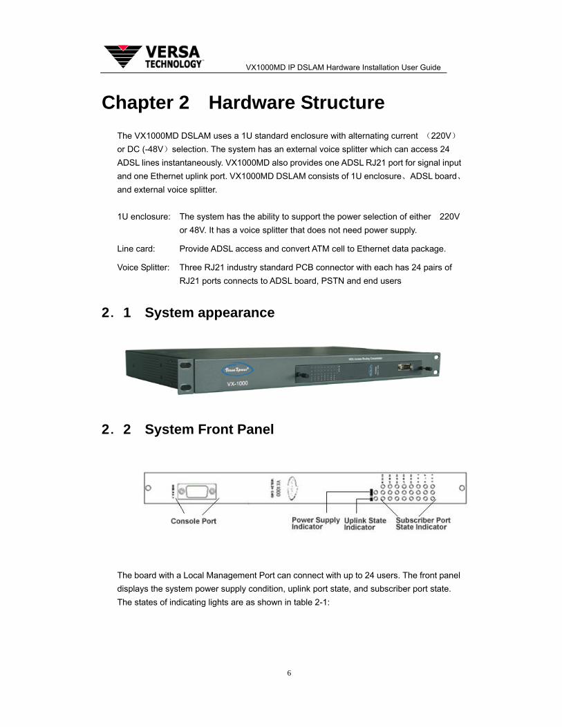
2.1 System appearance
2.2 System Front Panel
The board with a Local Management Port can connect with up to 24 users. The front panel displays the system power supply condition, uplink port state, and subscriber port state. The states of indicating lights are as shown in table 2-1:
VX1000MD IP DSLAM Hardware Installation User Guide
7
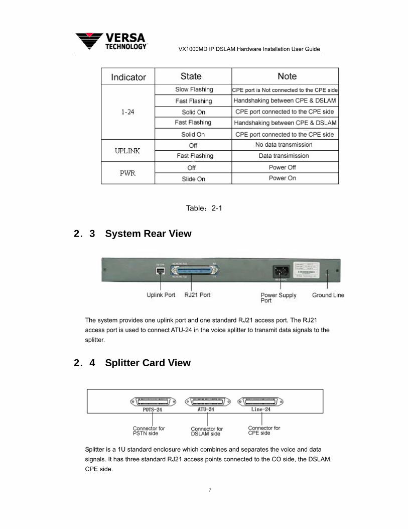
Table:2-1
2.3 System Rear View
The system provides one uplink port and one standard RJ21 access port. The RJ21 access port is used to connect ATU-24 in the voice splitter to transmit data signals to the splitter.
2.4 Splitter Card View
Splitter is a 1U standard enclosure which combines and separates the voice and data signals. It has three standard RJ21 access points connected to the CO side, the DSLAM, CPE side.
VX1000MD IP DSLAM Hardware Installation User Guide
8
Chapter 3 Installation
3.1 Installation Preparation
3.1.1 Equipment and Accessories Check-up
After unpacking the VX1000MD IP-DSLAM, please check whether the equipment and accessories sets are complete.
• One VX1000MD (including service card)
• One set of enclosure installation accessories (two L brackets and several screws/bolts)
• One subscriber cable set
• One DC (or AC) power cord
• One RS-232 configuration cable
• One user manual
• User registration/warranty card
Above is the basic configuration list in the package. Please refer to the purchase order for the actual parts and their quantity.
If anything in the package is damaged or missing, please contact the distributor or the nearest Versa Technology, Inc. support personnel immediately. Please keep all the packing materials for future use in case of repacking the equipment for RMA purposes. Please fill in the user registration/warranty card carefully and send your information back to Customer Service Department of Versa Technology, Inc. Your customer and service rights can be guaranteed by doing this.
3.1.2 Environmental Requirement
VX1000MD IP-DSLAM installation and operation environment should meet the following requirements.
Temperature/Humidity Requirement To guarantee the normal operation of the equipment and extend its life time, the temperature and humidity in the equipment room should be kept within the allowed range. The temperature should be limited to 0~40°. Recommended temperature is 18~25°. Overly high temperature will damage the equipment. The humidity levels should be limited
VX1000MD IP DSLAM Hardware Installation User Guide
9
to 10% to 90%. Recommended range is 20% to 60%. Long-term high humidity in the equipment will lead to degradation of insulation materials and even electricity leakage. It’s also not good if the humidity is too low since that will lead to harmful static.
Cleanliness Requirement The normal operation of the equipment requires certain sanitary levels to be maintained. Contact with dust should be avoided since it is harmful to the equipment’s safety and operation. Dust removal activities should be constant in the equipment room. It is recommended that the dust levels should be less than 180mg/M3. Printers and copiers should be placed away from the equipment as far as possible. This will prevent the paper pieces and toner powder from being sucked into the equipment.
Heat Dissipation Requirement The equipment room should have good ventilation to meet the heat dissipation requirement. Do not block the air exhaust. Do not place heavy items on the equipment.
Power Supply Requirement Reliable 48V DC or 220V AC power supplies should be provided in the equipment room. In the case where only AC power supply is available, the AC-to-DC power supply system should be provided. In addition, a backup power system is recommended to guarantee the normal operation of the equipment. Meanwhile, there should be good grounding connection in the equipment room to prevent electrical shocks and overloads.
Other Requirements The equipment room should be well illuminated. It is recommended that brightness should be 500 to 700Lu/M2. The equipment room should be guarded or equipped with a security device to prevent vandalism.
3.1.3 Safety Requirement
In order to guarantee the normal operation of the equipment and to provide safe handling for personnel, the following safety guide must be followed during operation.
Avoid contacts of any kind with any form of liquid to the equipment which might create a short circuit or an electrical shock.
Do not place the equipment near a heat source which may cause performance degradation or hardware damage. Avoid direct sun light exposure on the hardware.
Use a soft dry cloth to clean the equipment. Do not use cleansing agents to clean it.
Turn the power off before uninstalling or moving the equipment.
Human body static will damage the internal components and PCB parts of the equipment. Please hold the edge of the PCB board/interface module when moving
VX1000MD IP DSLAM Hardware Installation User Guide
10
them. Do not touch the components and PCB directly to prevent static damage from harming the parts. An anti-static wrist band is recommended during operation.
In order to protect the line interface port, lightening protection device should be deployed when the equipment is connected to outdoor wire.
3.2 Installation Tools and Materials Preparation
3.2.1 Required Tools
Philips Screw Driver
Flat Screw Driver
Pliers
Anti-static wrist band
3.2.2 Cables
Power Cord
Serial Configuration Cable
Crossover Ethernet Cable
3.2.3 Other
A computer with Hyper-Terminal software installed.
3.3 Installation Procedure
A qualified technician is required for the VX1000MD IP-DSLAM installation and maintenance.
Prior to the installation, please check whether all the tools and materials are complete. Unpack the equipment and place it on a level surface. Follow the steps below to install the equipment.
3.3.1 Mount the Equipment on Rack
VX1000MD is built with a 1U high single board structure. It has small compact dimensions and a very light weight. VX1000MD can be placed at the top of desk or mounted on a rack.
VX1000MD IP DSLAM Hardware Installation User Guide
11
Please use the following steps to mount it on the rack.
First, mount the L-shape bracket to the VX1000MD by using the supplied screws.
Second, lift the VX1000MD and push it into the rack from front side until the front panel is aligned with the side bard of rack.
Third, align the screw holes on rack with that on the enclosure. Secure the enclosure by using the supplied screws.
Fourth, Make sure the ground connection is good. Usually the rack has ground connection so no separate grounding is required for the equipment if it is mounted on the rack. However, if the rack does not have good grounding, extra grounding connections should be added to the equipment by connecting the grounding post on the enclosure to the grounding terminal of the equipment room.
3.3.2 Line Card Installation
First, make sure that power is switched off before you proceed.
Second, make sure that VX1000MD has good ground connections. Installer must wear an anti-static wrist band.
Third, remove the baffle covering the line card slot. Keep the cover in a secure place for future use.
Fourth, unpack the line card. Hold the card with both hands at the thumb screws on the left and right ends. Align the card to the slot and push it in along the slot by using two hands. Stop when the card hits the connector on the backplane.
Fifth, push the card in firmly and gently by using two hands so that the line card is securely connected to the backplane connector. Tighten the thumb screws to secure the whole line card.
The steps to remove the line cars are the reverse of that for installation.
Note: Line card supports hot-swappable.
3.3.3 Splitter Installation
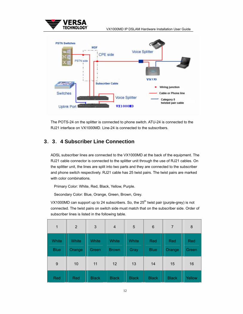
Installation of splitter unit is similar to that of 1U DSLAM enclosure. Place the splitter unit close to the DSLAM since the RJ21 cable connecting the splitter and DSLAM has limited fixed length. After the splitter unit is secured, the connection between equipments is illustrated as following diagram.
VX1000MD IP DSLAM Hardware Installation User Guide
12
The POTS-24 on the splitter is connected to phone switch. ATU-24 is connected to the RJ21 interface on VX1000MD. Line-24 is connected to the subscribers.
3.3.4 Subscriber Line Connection
ADSL subscriber lines are connected to the VX1000MD at the back of the equipment. The RJ21 cable connector is connected to the splitter unit through the use of RJ21 cables. On the splitter unit, the lines are split into two parts and they are connected to the subscriber and phone switch respectively. RJ21 cable has 25 twist pairs. The twist pairs are marked with color combinations.
Primary Color: White, Red, Black, Yellow, Purple.
Secondary Color: Blue, Orange, Green, Brown, Grey.
VX1000MD can support up to 24 subscribers. So, the 25th twist pair (purple-grey) is not connected. The twist pairs on switch side must match that on the subscriber side. Order of subscriber lines is listed in the following table.
1 2 3 4 5 6 7 8
White
Blue
White
Orange
White
Green
White
Brown
White
Gray
Red
Blue
Red
Orange
Red
Green
9 10 11 12 13 14 15 16
Red Red Black Black Black Black Black Yellow
VX1000MD IP DSLAM Hardware Installation User Guide
13
Brown Gray Blue Orange Green Brown Gray Blue
17 18 19 20 21 22 23 24
Yellow
Orange
Yellow
Green
Yellow
Brown
Yellow
Gray
Purple
Blue
Purple
Orange
Purple
Green
Purple
Brown
Table:3-1
3.3.5 Ethernet Cable Connection
The VX1000MD Ethernet port should be connected to the ISP network equipment through a UTP-5 or STP cable.
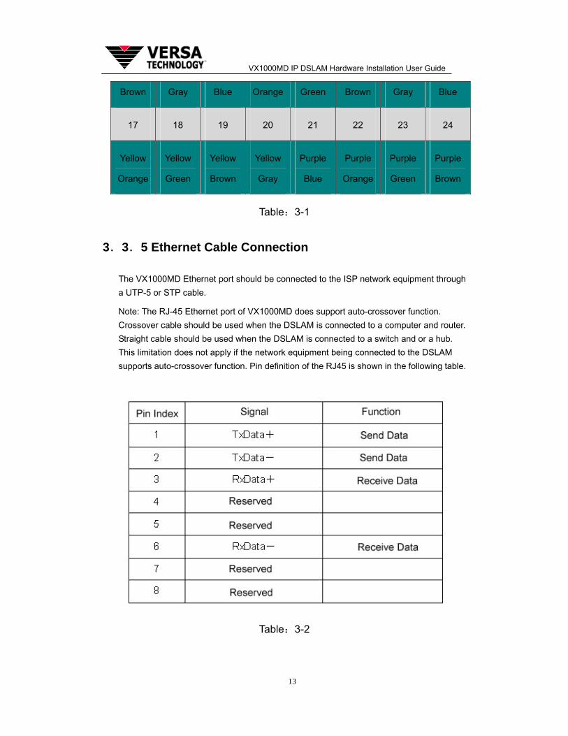
Note: The RJ-45 Ethernet port of VX1000MD does support auto-crossover function. Crossover cable should be used when the DSLAM is connected to a computer and router. Straight cable should be used when the DSLAM is connected to a switch and or a hub. This limitation does not apply if the network equipment being connected to the DSLAM supports auto-crossover function. Pin definition of the RJ45 is shown in the following table.
Table:3-2
VX1000MD IP DSLAM Hardware Installation User Guide
14
Ethernet Cable Crimping Guide
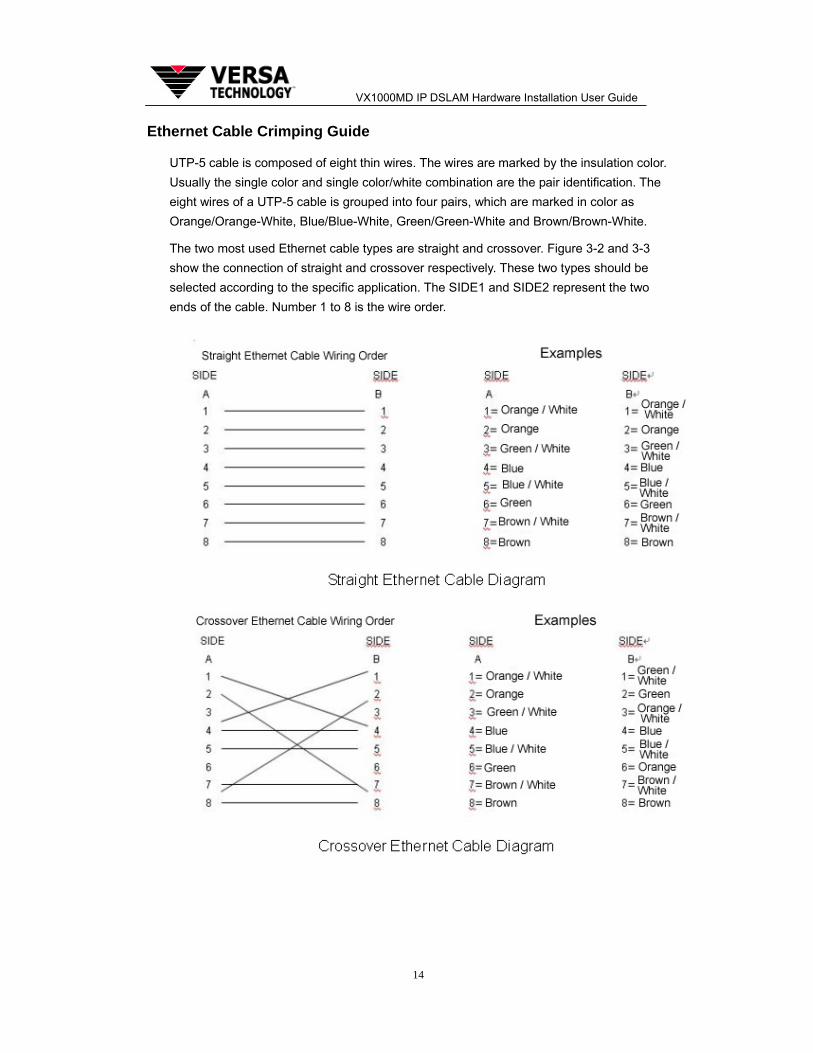
UTP-5 cable is composed of eight thin wires. The wires are marked by the insulation color. Usually the single color and single color/white combination are the pair identification. The eight wires of a UTP-5 cable is grouped into four pairs, which are marked in color as Orange/Orange-White, Blue/Blue-White, Green/Green-White and Brown/Brown-White.
The two most used Ethernet cable types are straight and crossover. Figure 3-2 and 3-3 show the connection of straight and crossover respectively. These two types should be selected according to the specific application. The SIDE1 and SIDE2 represent the two ends of the cable. Number 1 to 8 is the wire order.
VX1000MD IP DSLAM Hardware Installation User Guide
15
3.3.6 Console Port Connection
VX1000MD IP-DSLAM has one RS-232 interface which can be connected to PC through serial cable. By using this interface, DSLAM can be configured and managed locally through the command line interface.
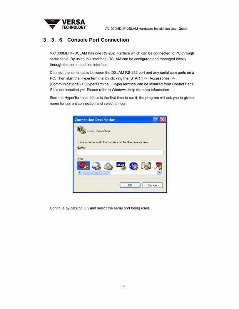
Connect the serial cable between the DSLAM RS-232 port and any serial com ports on a PC. Then start the HyperTerminal by clicking the [START] -> [Accessories] -> [Communications] -> [HyperTerminal]. HyperTerminal can be installed from Control Panel if it is not installed yet. Please refer to Windows Help for more information.
Start the HyperTerminal. If this is the first time to run it, the program will ask you to give a name for current connection and select an icon.
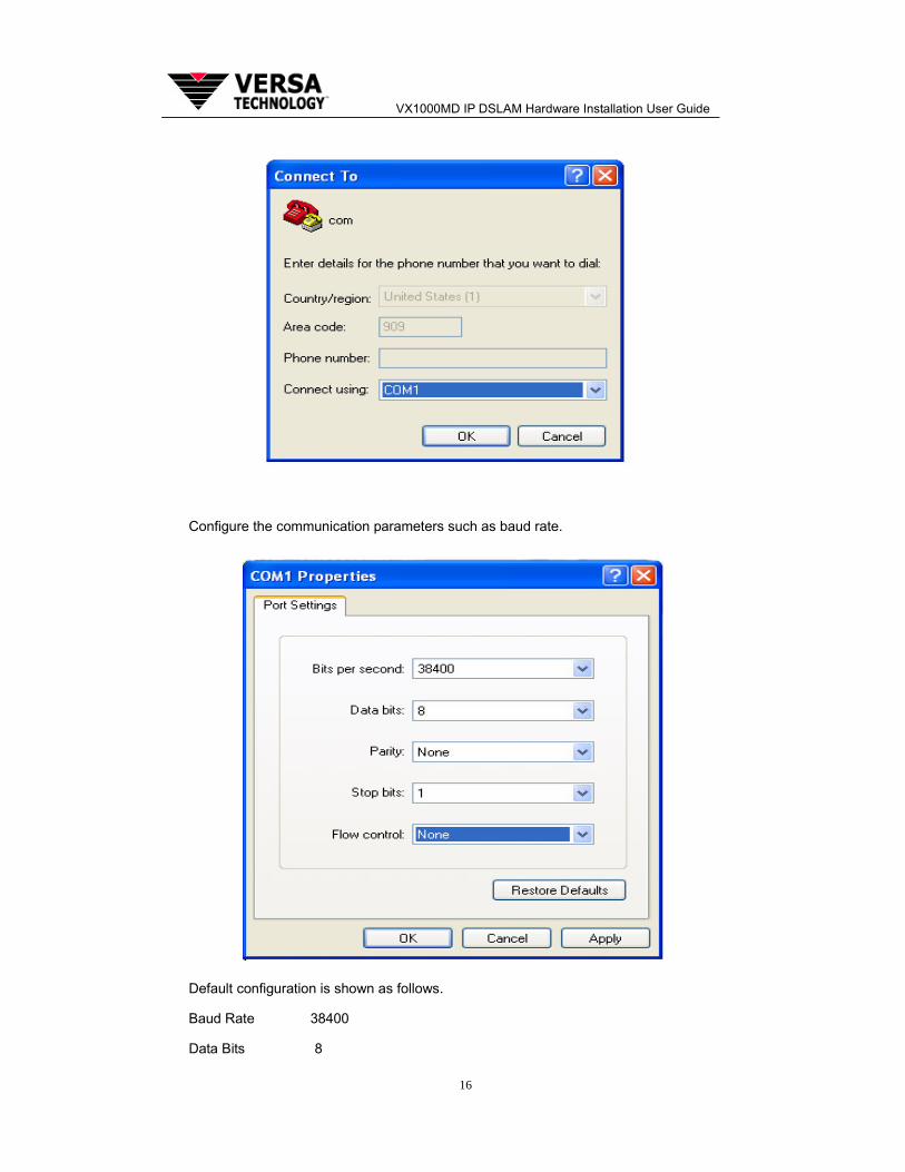
Continue by clicking OK and select the serial port being used.
VX1000MD IP DSLAM Hardware Installation User Guide
16
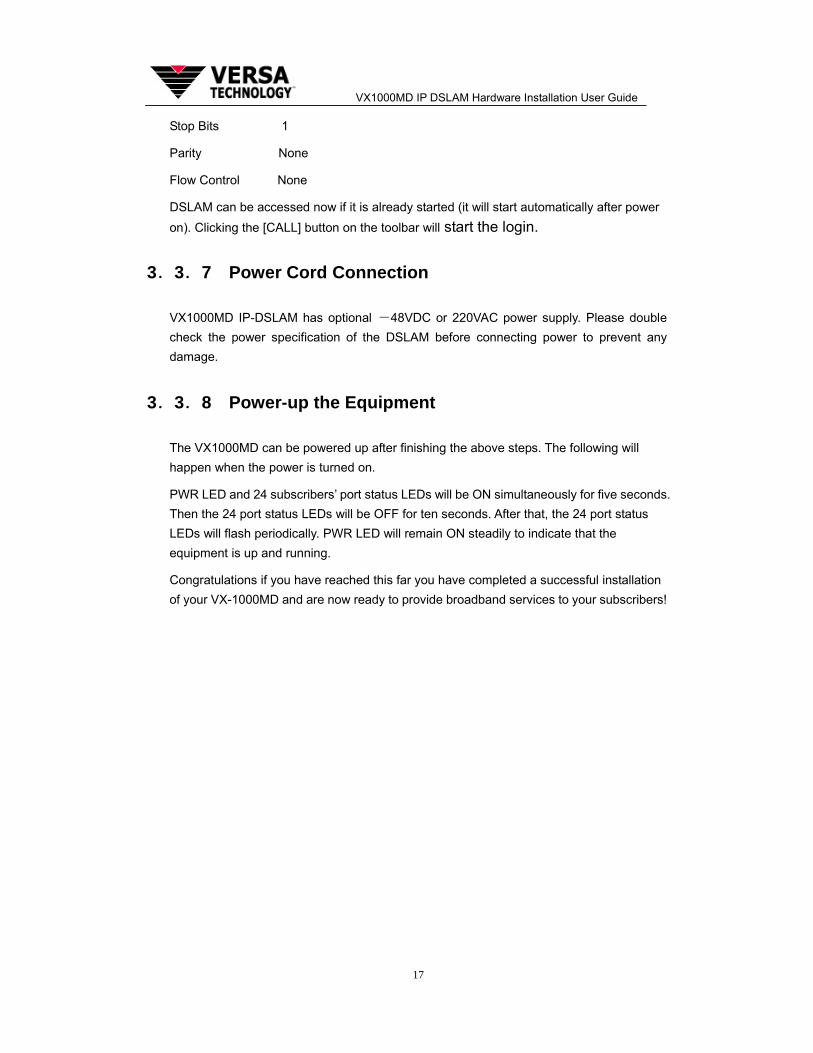
Configure the communication parameters such as baud rate.
Default configuration is shown as follows.
Baud Rate 38400
Data Bits 8
VX1000MD IP DSLAM Hardware Installation User Guide
17
Stop Bits 1
Parity None
Flow Control None
DSLAM can be accessed now if it is already started (it will start automatically after power on). Clicking the [CALL] button on the toolbar will start the login.
3.3.7 Power Cord Connection
VX1000MD IP-DSLAM has optional -48VDC or 220VAC power supply. Please double check the power specification of the DSLAM before connecting power to prevent any damage.
3.3.8 Power-up the Equipment
The VX1000MD can be powered up after finishing the above steps. The following will happen when the power is turned on.
PWR LED and 24 subscribers’ port status LEDs will be ON simultaneously for five seconds. Then the 24 port status LEDs will be OFF for ten seconds. After that, the 24 port status LEDs will flash periodically. PWR LED will remain ON steadily to indicate that the equipment is up and running.
Congratulations if you have reached this far you have completed a successful installation of your VX-1000MD and are now ready to provide broadband services to your subscribers!