Embed Size (px)
Citation preview
Veritas Storage Foundation™ and High Availability Solutions HA and Disaster Recovery Solutions Guide for Microsoft SQL 2000 and 2005
Windows Server 2003, Windows Server 2008
5.1 Service Pack 2
Veritas Storage Foundation and HA Solutions HA and Disaster Recovery Solutions Guide for Microsoft SQL 2000 and 2005
The software described in this book is furnished under a license agreement and may be used only in accordance with the terms of the agreement.
Product version: 5.1. Service Pack 2
Document version: 5.1.SP2.1
Legal Notice
Copyright © 2011 Symantec Corporation. All rights reserved.Symantec, the Symantec Logo, Veritas and Veritas Storage Foundation are trademarks or registered trademarks of Symantec Corporation or its affiliates in the U.S. and other countries. Other names may be trademarks of their respective owners.This Symantec product may contain third party software for which Symantec is required to provide attribution to the third party (“Third Party Programs”). Some of the Third Party Programs are available under open source or free software licenses. The License Agreement accompanying the Software does not alter any rights or obligations you may have under those open source or free software licenses. Please see the Third Party Legal Notice file accompanying this Symantec product for more information on the Third Party Programs.The product described in this document is distributed under licenses restricting its use, copying, distribution, and decompilation/reverse engineering. No part of this document may be reproduced in any form by any means without prior written authorization of Symantec Corporation and its licensors, if any. THE DOCUMENTATION IS PROVIDED "AS IS" AND ALL EXPRESS OR IMPLIED CONDITIONS, REPRESENTATIONS AND WARRANTIES, INCLUDING ANY IMPLIED WARRANTY OF MERCHANTABILITY, FITNESS FOR A PARTICULAR PURPOSE OR NON-INFRINGEMENT, ARE DISCLAIMED, EXCEPT TO THE EXTENT THAT SUCH DISCLAIMERS ARE HELD TO BE LEGALLY INVALID. SYMANTEC CORPORATION SHALL NOT BE LIABLE FOR INCIDENTAL OR CONSEQUENTIAL DAMAGES IN CONNECTION WITH THE FURNISHING, PERFORMANCE, OR USE OF THIS DOCUMENTATION. THE INFORMATION CONTAINED IN THIS DOCUMENTATION IS SUBJECT TO CHANGE WITHOUT NOTICE.The Licensed Software and Documentation are deemed to be commercial computer software as defined in FAR 12.212 and subject to restricted rights as defined in FAR Section 52.227-19 "Commercial Computer Software - Restricted Rights" and DFARS 227.7202, "Rights in Commercial Computer Software or Commercial Computer Software Documentation", as applicable, and any successor regulations. Any use, modification, reproduction release, performance, display or disclosure of the Licensed Software and Documentation by the U.S. Government shall be solely in accordance with the terms of this Agreement.Symantec Corporation 350 Ellis Street Mountain View, CA 94043http://www.symantec.com
Technical SupportSymantec Technical Support maintains support centers globally. Technical Support’s primary role is to respond to specific queries about product features and functionality. The Technical Support group also creates content for our online Knowledge Base. The Technical Support group works collaboratively with the other functional areas within Symantec to answer your questions in a timely fashion. For example, the Technical Support group works with Product Engineering and Symantec Security Response to provide alerting services and virus definition updates.Symantec’s support offerings include the following:
■ A range of support options that give you the flexibility to select the right amount of service for any size organization
■ Telephone and/or web-based support that provides rapid response and up-to-the-minute information
■ Upgrade assurance that delivers automatic software upgrades protection
■ Global support purchased on a regional business hours or 24 hours a day, 7 days a week basis
■ Premium service offerings that include Account Management ServicesFor information about Symantec’s support offerings, you can visit our web site at the following URL:www.symantec.com/business/support/index.jspAll support services will be delivered in accordance with your support agreementand the then-current enterprise technical support policy.
Contacting Technical SupportCustomers with a current support agreement may access Technical Support information at the following URL:www.symantec.com/business/support/contact_techsupp_static.jspBefore contacting Technical Support, make sure you have satisfied the system requirements that are listed in your product documentation. Also, you should be at the computer on which the problem occurred, in case it is necessary to replicate the problem.When you contact Technical Support, please have the following informationavailable:
■ Product release level
■ Hardware information
■ Available memory, disk space, and NIC information
■ Operating system
■ Version and patch level
■ Network topology
■ Router, gateway, and IP address information
■ Problem description:■ Error messages and log files■ Troubleshooting that was performed before contacting Symantec■ Recent software configuration changes and network changes
Licensing and registrationIf your Symantec product requires registration or a license key, access our technical support web page at the following URL:www.symantec.com/business/support/
Customer serviceCustomer service information is available at the following URL:www.symantec.com/business/support/Customer Service is available to assist with non-technical questions, such as thefollowing types of issues:
■ Questions regarding product licensing or serialization
■ Product registration updates, such as address or name changes
■ General product information (features, language availability, local dealers)
■ Latest information about product updates and upgrades
■ Information about upgrade assurance and support contracts
■ Information about the Symantec Buying Programs
■ Advice about Symantec's technical support options
■ Nontechnical presales questions
■ Issues that are related to CD-ROMs or manuals

5
Support agreement resourcesIf you want to contact Symantec regarding an existing support agreement, please contact the support agreement administration team for your region as follows:
Asia-Pacific and Japan [email protected]
Europe, Middle-East, and Africa [email protected]
North America and Latin America [email protected]

6
Contents
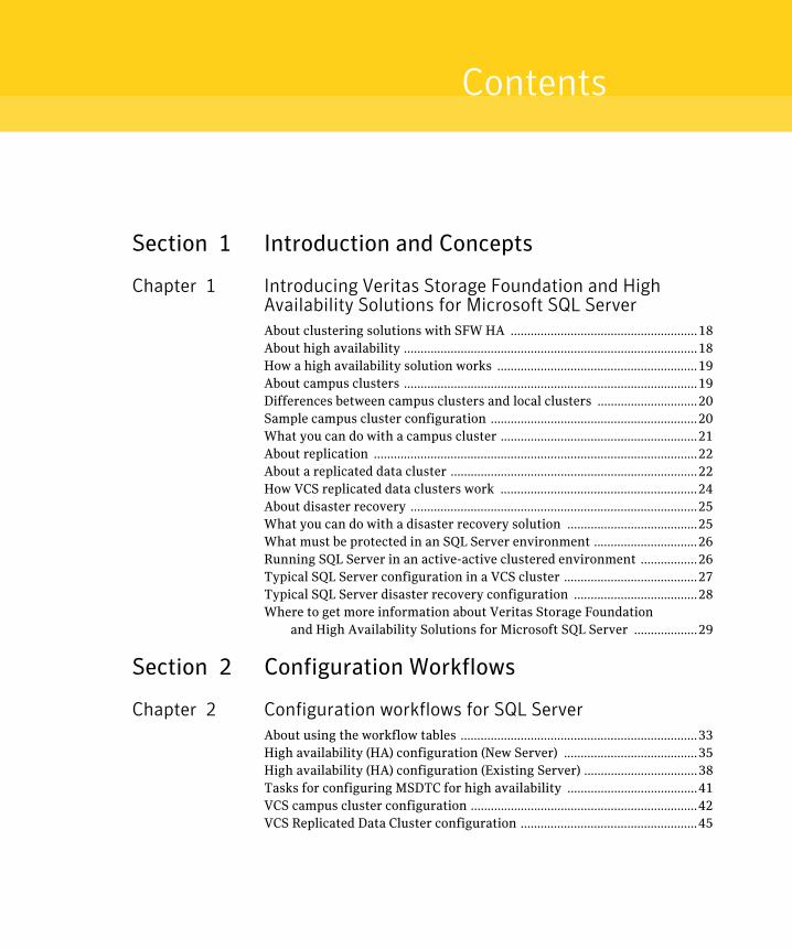
Section 1 Introduction and Concepts
Chapter 1 Introducing Veritas Storage Foundation and High Availability Solutions for Microsoft SQL ServerAbout clustering solutions with SFW HA ........................................................18About high availability ........................................................................................18How a high availability solution works ............................................................19About campus clusters ........................................................................................19Differences between campus clusters and local clusters ..............................20Sample campus cluster configuration ..............................................................20What you can do with a campus cluster ...........................................................21About replication .................................................................................................22About a replicated data cluster ..........................................................................22How VCS replicated data clusters work ...........................................................24About disaster recovery ......................................................................................25What you can do with a disaster recovery solution .......................................25What must be protected in an SQL Server environment ...............................26Running SQL Server in an active-active clustered environment .................26Typical SQL Server configuration in a VCS cluster ........................................27Typical SQL Server disaster recovery configuration .....................................28Where to get more information about Veritas Storage Foundation
and High Availability Solutions for Microsoft SQL Server ...................29
Section 2 Configuration Workflows
Chapter 2 Configuration workflows for SQL ServerAbout using the workflow tables .......................................................................33High availability (HA) configuration (New Server) ........................................35High availability (HA) configuration (Existing Server) ..................................38Tasks for configuring MSDTC for high availability .......................................41VCS campus cluster configuration ....................................................................42VCS Replicated Data Cluster configuration .....................................................45
8 Contents
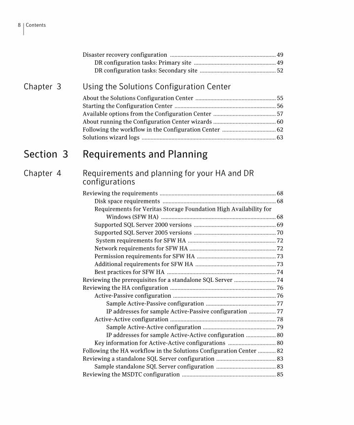
Disaster recovery configuration ....................................................................... 49DR configuration tasks: Primary site ....................................................... 49DR configuration tasks: Secondary site ................................................... 52
Chapter 3 Using the Solutions Configuration CenterAbout the Solutions Configuration Center ...................................................... 55Starting the Configuration Center .................................................................... 56Available options from the Configuration Center .......................................... 57About running the Configuration Center wizards .......................................... 60Following the workflow in the Configuration Center .................................... 62Solutions wizard logs .......................................................................................... 63
Section 3 Requirements and Planning
Chapter 4 Requirements and planning for your HA and DR configurationsReviewing the requirements .............................................................................. 68
Disk space requirements ............................................................................ 68Requirements for Veritas Storage Foundation High Availability for
Windows (SFW HA) ............................................................................. 68Supported SQL Server 2000 versions ....................................................... 69Supported SQL Server 2005 versions ....................................................... 70 System requirements for SFW HA ........................................................... 72Network requirements for SFW HA .......................................................... 72Permission requirements for SFW HA ..................................................... 73Additional requirements for SFW HA ...................................................... 73Best practices for SFW HA ......................................................................... 74
Reviewing the prerequisites for a standalone SQL Server ............................ 74Reviewing the HA configuration ....................................................................... 76
Active-Passive configuration ..................................................................... 76Sample Active-Passive configuration ............................................... 77IP addresses for sample Active-Passive configuration .................. 77
Active-Active configuration ....................................................................... 78Sample Active-Active configuration ................................................. 79IP addresses for sample Active-Active configuration .................... 80
Key information for Active-Active configurations ................................ 80Following the HA workflow in the Solutions Configuration Center ............ 82Reviewing a standalone SQL Server configuration ........................................ 83
Sample standalone SQL Server configuration ........................................ 83Reviewing the MSDTC configuration ............................................................... 85
9Contents
Reviewing the campus cluster configuration ..................................................88Campus cluster failover using the ForceImport attribute .....................89Reinstating faulted hardware in a campus cluster .................................91
Reviewing the Replicated Data Cluster configuration ...................................92Sample replicated data cluster configuration .........................................92
About setting up a Replicated Data Cluster configuration ............................94About setting up replication ......................................................................95About configuring and migrating the service group ..............................95
Reviewing the disaster recovery configuration ..............................................96Sample disaster recovery configuration ..................................................98IP addresses for sample disaster recovery configuration .....................99Supported disaster recovery configurations for service
group dependencies ...........................................................................100
Section 4 Deployment
Chapter 5 Installing and configuring SFW HAConfiguring the storage hardware and network ...........................................104Installing Veritas Storage Foundation HA for Windows .............................106
Setting Windows driver signing options ................................................106Installing Symantec Trusted certificate for unsigned drivers ...107
Installing Storage Foundation HA for Windows ...................................108Resetting the driver signing options ......................................................111
Configuring cluster disk groups and volumes for SQL Server ....................112About cluster disk groups and volumes .................................................112Prerequisites for configuring cluster disk groups and volumes ........113Considerations for converting existing shared storage to
cluster disk groups and volumes .....................................................114Considerations for disks and volumes for campus clusters ................115Considerations for volumes for a VVR configuration ..........................115Considerations for disk groups and volumes for multiple
instances ..............................................................................................116Sample disk group and volume configuration ......................................117MSDTC sample disk group and volume configuration ........................118Viewing the available disk storage ..........................................................118Creating a cluster disk group ...................................................................118Creating volumes .......................................................................................120
About managing disk groups and volumes ....................................................125Importing a disk group and mounting a volume ..................................125Unmounting a volume and deporting a disk group ..............................125Adding drive letters to mount the volumes ...........................................126Deporting the cluster disk group .............................................................127
10 Contents
Configuring the cluster .....................................................................................128Configuring notification ...........................................................................139
Chapter 6 Installing SQL ServerAbout installing multiple SQL instances .......................................................143Verifying that SQL Server databases and logs are moved to
shared storage ............................................................................................144Installing and configuring SQL Server 2000 on the first cluster node .....144Installing and configuring SQL Server 2005 on the first cluster node .....147Installing SQL Server on the second cluster node ........................................149Setting the internal name of the clustered instance for
SQL Server 2000 .........................................................................................151Creating a SQL Server user-defined database ...............................................153Completing configuration steps in SQL Server .............................................154
Moving the tempdb database if using VVR for disaster recovery ......154Assigning ports for multiple SQL Server instances .............................154
Chapter 7 Configuring SQL Server for failoverAbout configuring the VCS SQL Server service group ................................156
Service group requirements for Active-Active configurations ..........156Prerequisites for configuring the SQL service group ...........................156Creating the SQL Server service group ..................................................158
Verifying the SQL Server cluster configuration ...........................................164Configuring an MSDTC Server service group ...............................................165
Prerequisites for MSDTC configuration ................................................165Creating an MSDTC Server service group .............................................165
About configuring the MSDTC client for SQL Server ..................................169Configuring MSDTC client on Windows 2003 .......................................169Configuring MSDTC client on Windows 2008 .......................................170
About the VCS Application Manager utility ..................................................171Viewing DTC transaction information ...........................................................171Modifying a SQL Server service group to add VMDg and
MountV resources ......................................................................................173Determining additional steps needed .............................................................174
Chapter 8 Configuring campus clusters for SQL ServerTasks for configuring campus clusters ..........................................................176Modifying the IP resource in the SQL Server service group .......................176Verifying the campus cluster: Switching the service group .......................177Setting the ForceImport attribute to 1 after a site failure ..........................178
11Contents
Chapter 9 Configuring Replicated Data Clusters for SQL ServerTasks for configuring Replicated Data Clusters ...........................................180Creating the primary system zone ..................................................................182Creating a parallel environment in the secondary zone ..............................183Adding the systems in the secondary zone to the cluster ...........................184Setting up security for VVR .............................................................................190
Configuring the VxSAS service ................................................................190Setting up the Replicated Data Sets (RDS) .....................................................193
Prerequisites for setting up the RDS for the primary and secondary zones .................................................................................193
Creating the Replicated Data Sets with the wizard ..............................193Configuring a hybrid RVG service group for replication .............................205
Creating the RVG service group ..............................................................205Configuring the RVG service group for RDC replication .....................206
Configuring the IP and NIC resources ............................................207Configuring the VMDg resources ....................................................208Configuring the VMDg resources for the disk group for the
user-defined database ...............................................................210Adding the VVR RVG resources for the disk groups ....................212Linking the VVR RVG resources to establish dependencies .......215Deleting the VMDg resource from the SQL Server service
group ............................................................................................216Configuring the RVGPrimary resources ................................................217
Creating the RVG Primary resources ..............................................217Linking the RVG Primary resources to establish dependencies .218Bringing the RVG Primary resources online .................................219
Configuring the primary system zone for the RVG ..............................220Setting a dependency between the service groups .......................................220Adding the nodes from the secondary zone to the RDC ..............................221
Adding the nodes from the secondary zone to the RVG service group ....................................................................................................221
Configuring secondary zone nodes in the RVG service group ............223Configuring the IP resources for failover ..............................................224Adding the nodes from the secondary zone to the SQL Server 2000
or 2005 service group ........................................................................225Configuring the zones in the SQL Server service group ......................226
Verifying the RDC configuration .....................................................................227Bringing the service group online ...........................................................227Switching online nodes .............................................................................227
Additional instructions for GCO disaster recovery ......................................228
12 Contents
Chapter 10 Configuring disaster recovery for SQL ServerTasks for configuring disaster recovery for SQL Server .............................232Guidelines for installing SFW HA and configuring the cluster on the
secondary site .............................................................................................236Verifying your primary site configuration ....................................................237Setting up your replication environment ......................................................237
Setting up security for VVR .....................................................................238Requirements for EMC SRDF array-based hardware replication ......240
Software requirements for configuring EMC SRDF .....................240Replication requirements for EMC SRDF .......................................241
Requirements for Hitachi TrueCopy array-based hardware replication ...........................................................................................242Software requirements for Hitachi TrueCopy ..............................242Replication requirements for Hitachi TrueCopy ..........................243
Assigning user privileges (secure clusters only) ..........................................245Configuring disaster recovery with the DR wizard ......................................246Cloning the storage on the secondary site using the DR wizard
(VVR replication option) ...........................................................................250Creating temporary storage on the secondary site using the DR wizard
(array-based replication) ..........................................................................254Installing and configuring SQL Server on the
secondary site .............................................................................................258Cloning the service group configuration from the
primary to the secondary site ..................................................................258Configuring replication and global clustering ..............................................262
Configuring VVR replication and global clustering .............................262Configuring EMC SRDF replication and global clustering ..................270
Optional settings for EMC SRDF .....................................................272Configuring Hitachi TrueCopy replication and global clustering ......273
Optional settings for HTC .................................................................276Configuring global clustering only .........................................................276
Verifying the disaster recovery configuration .............................................278Establishing secure communication within the
global cluster (optional) ............................................................................280Adding multiple DR sites (optional) ................................................................282Recovery procedures for service group dependencies ................................283
13Contents
Chapter 11 Testing fault readiness by running a fire drillAbout disaster recovery fire drills ..................................................................287About the Fire Drill Wizard ..............................................................................288
About Fire Drill Wizard general operations ..........................................288About Fire Drill Wizard operations in a VVR environment ................289
Preparing the fire drill configuration .............................................289Running the fire drill .........................................................................290Restoring the fire drill configuration .............................................290Deleting the fire drill configuration ................................................290
About Fire Drill Wizard operations in a Hitachi TrueCopy or EMC SRDF environment ...................................................................290Preparing the fire drill configuration .............................................291Running the fire drill .........................................................................291Restoring the fire drill configuration .............................................292Deleting the fire drill configuration ................................................292
About post-fire drill scripts ..............................................................................292Tasks for configuring and running fire drills ...............................................294Prerequisites for a fire drill ..............................................................................296
Prerequisites for a fire drill in a VVR environment .............................296Prerequisites for a fire drill in a Hitachi TrueCopy environment ......297Prerequisites for a fire drill in an EMC SRDF environment ................298
Preparing the fire drill configuration .............................................................299System Selection panel details ................................................................301Service Group Selection panel details ....................................................301Secondary System Selection panel details .............................................301Fire Drill Service Group Settings panel details .....................................302Disk Selection panel details ......................................................................302Hitachi TrueCopy Path Information panel details ...............................303HTCSnap Resource Configuration panel details ...................................303SRDFSnap Resource Configuration panel details .................................304Fire Drill Preparation panel details ........................................................304
Running a fire drill ............................................................................................305Recreating a fire drill configuration that has changed ................................307Restoring the fire drill system to a prepared state .......................................309Deleting the fire drill configuration ...............................................................310
Index 313

14 Contents
Section
1 Introduction and ConceptsThis section contains the following chapters:
■ Introducing Veritas Storage Foundation and High Availability Solutions for Microsoft SQL Server

16
Chapter
1Introducing Veritas Storage Foundation and High Availability Solutions for Microsoft SQL Server
This chapter contains the following topics:
■ About clustering solutions with SFW HA
■ About high availability
■ How a high availability solution works
■ About campus clusters
■ Differences between campus clusters and local clusters
■ Sample campus cluster configuration
■ What you can do with a campus cluster
■ About replication
■ About a replicated data cluster
■ How VCS replicated data clusters work
■ About disaster recovery
■ What you can do with a disaster recovery solution
■ What must be protected in an SQL Server environment
■ Running SQL Server in an active-active clustered environment
■ Typical SQL Server configuration in a VCS cluster
18 Introducing Veritas Storage Foundation and High Availability Solutions for Microsoft SQL ServerAbout clustering solutions with SFW HA
■ Typical SQL Server disaster recovery configuration
■ Where to get more information about Veritas Storage Foundation and High Availability Solutions for Microsoft SQL Server
About clustering solutions with SFW HAVeritas Storage Foundation HA for Windows (SFW HA) provides the following clustering solutions for high availability and disaster recovery:
■ High availability failover cluster in an active/passive configuration on the same site
■ Campus cluster, in a two-node configuration with each node on a separate site
■ Replicated data cluster, with a primary zone and a secondary zone existing within a single cluster, which can stretch over two buildings or data centers connected with Ethernet
■ Wide area disaster recovery, with a separate cluster on a secondary site, with replication support using Veritas Volume Replicator or hardware replication
About high availabilityThe term high availability refers to a state where data and applications are highly available because software or hardware is in place to maintain the continued functioning in the event of computer failure. High availability can refer to any software or hardware that provides fault tolerance, but generally the term has become associated with clustering.
A cluster is a group of independent computers working together to ensure that mission-critical applications and resources are as highly available as possible. The group is managed as a single system, shares a common namespace, and is specifically designed to tolerate component failures and to support the addition or removal of components in a way that is transparent to users.
Local clustering provides high availability through database and application failover. This solution provides local recovery in the event of application, operating system, or hardware failure, and minimizes planned and unplanned application downtime.
The high availability solution includes procedures for installing and configuring clustered ?SQL Server? environments using Veritas Storage Foundation HA for Windows (SFW HA). SFW HA includes Veritas Storage Foundation for Windows and Veritas Cluster Server.
19Introducing Veritas Storage Foundation and High Availability Solutions for Microsoft SQL ServerHow a high availability solution works
Setting up the clustered environment is also the first step in creating a wide-area disaster recovery solution using a secondary site.
How a high availability solution worksKeeping data and applications functioning 24 hours a day and seven days a week is the desired norm for critical applications today. Clustered systems have several advantages over standalone servers, including fault tolerance, high availability, scalability, simplified management, and support for rolling upgrades.
Using Veritas Storage Foundation HA for Windows as a local high availability solution paves the way for a wide-area disaster recovery solution in the future.
A high availability solution is built on top of a backup strategy and provides the following benefits:
■ Reduces planned and unplanned downtime.
■ Serves as a local and wide-area failover (rather than load-balancing) solution. Enables failover between sites or between clusters.
■ Manages applications and provides an orderly way to bring processes online and take them offline.
■ Consolidates hardware in larger clusters. The HA environment accommodates flexible fail over policies, active-active configurations, and shared standby servers for SQL Server.
About campus clustersCampus clusters are clusters in separate buildings (or sites) with mirrored SAN-attached storage located in each building. Typical campus clusters involve two sites; you can use more than two sites for additional redundancy. In a typical configuration, each node has its own storage array and contains mirrored data of the storage on the other array.
Campus clusters are usually located across a campus or a city but can range over much wider distances if their infrastructure supports it, using Fibre Channel SANs and long-wave optical technologies.
This solution provides a level of high availability that is above mirroring or clustering at a single site but is not as complex as disaster recovery with replication.
20 Introducing Veritas Storage Foundation and High Availability Solutions for Microsoft SQL ServerDifferences between campus clusters and local clusters
Differences between campus clusters and local clusters
The procedures for setting up a campus cluster are nearly the same as those for local clusters, except that a campus cluster has the nodes located in separate buildings, so the hardware setup requires SAN interconnects that allows these connections. Also, in a campus cluster, each node has its own storage array rather than having a shared storage array between the two clusters. Both local clusters and campus clusters have SFW dynamic disk groups and volumes, but the volumes on each campus cluster node are mirrors of one another.
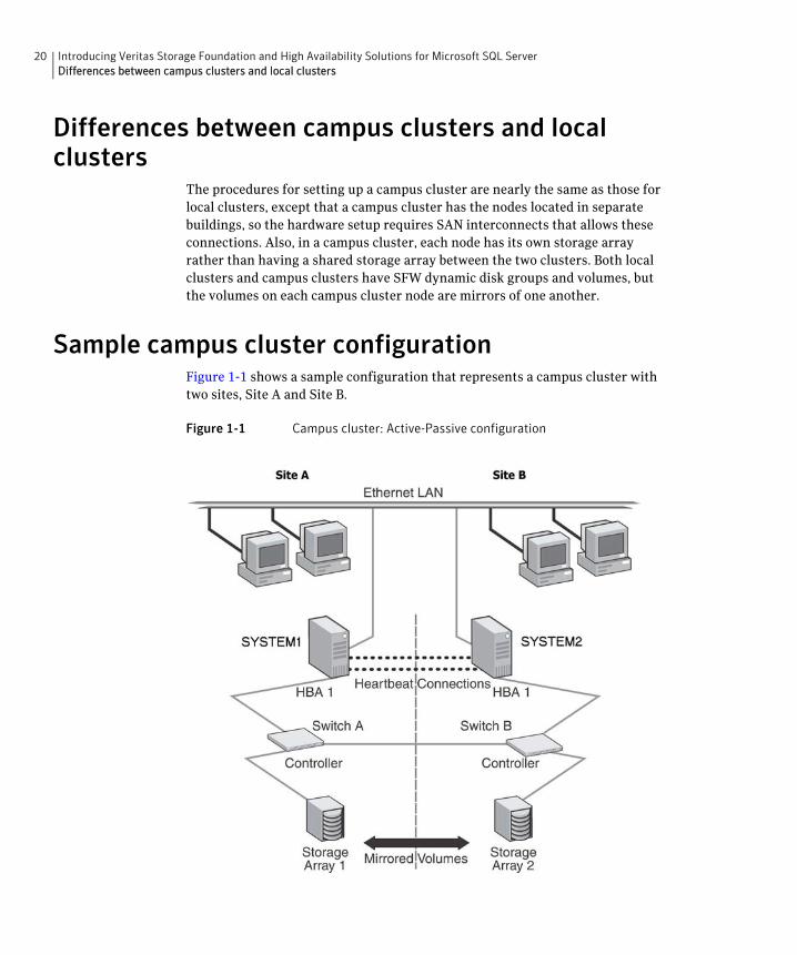
Sample campus cluster configurationFigure 1-1 shows a sample configuration that represents a campus cluster with two sites, Site A and Site B.
Figure 1-1 Campus cluster: Active-Passive configuration
21Introducing Veritas Storage Foundation and High Availability Solutions for Microsoft SQL ServerWhat you can do with a campus cluster
With SFW, a campus cluster can be set up using a Veritas Cluster Server (VCS) configuration. Both configurations involve setting up a single cluster with two nodes that are in separate buildings and are connected via a single subnet and Fibre Channel SAN. Each node has its own storage array with an equal number of disks and contains mirrored data of the storage on the other array. SFW provides the mirrored storage and the disk groups that make it possible to fail over the storage by deporting the disk groups on one node and importing them on the other.
If a site failure occurs in a two-node campus cluster, the remaining cluster node will not be able to bring the cluster disk groups online because it cannot reserve a majority of disks in the disk groups. To allow for failover to the other site, a procedure forces the import to the other node, allowing a cluster disk group to be brought online on another node when that node has a minority of the cluster disks.
Implementing these force import procedures should be done with care. The primary site may appear to have failed but what really has happened is that both the storage interconnect between sites and the heartbeats have been lost. In that case, cluster disk groups can still be online on the primary node. If a force import is done so that the data can be accessed on the secondary site, the cluster disks will be online on both sites, risking data corruption.
What you can do with a campus clusterAdministrators can use campus clusters to protect data from natural disasters, such as floods and hurricanes, and unpredictable power outages. Campus clusters provide disaster protection when an entire site goes down.
In the event of a site disaster, such as power failure in a building, campus clusters offer a level of high availability that surpasses mirroring or clustering at a single site by dispersing the clustered servers into different buildings or sites. This environment also provides a simpler solution for disaster recovery than a more elaborate SFW HA DR environment with replication software; however, a campus cluster generally stretches a shorter distance than a replication-based solution depending on the hardware.
22 Introducing Veritas Storage Foundation and High Availability Solutions for Microsoft SQL ServerAbout replication
About replicationThe term replication refers to the use of a tool or service to automate the process of maintaining a consistent copy of data from a designated source (primary site) on one or more remote locations (secondary sites).
In the event that the primary site data center is destroyed, the application data is readily available at the remote site, and the application can be restarted at the remote site.
SFW HA provides Veritas Volume Replicator (VVR) for use in replication. VVR can be used for replication in either a replicated data cluster (RDC) or a wide area disaster recovery solution.
The SFW HA disaster recovery solution also supports hardware replication.
For more information on VVR refer to the Veritas Volume Replicator, Administrator’s Guide.
About a replicated data clusterA Replicated Data Cluster (RDC) uses data replication, instead of shared storage, to assure data access to all the nodes in a cluster.
The Replicated Data Cluster configuration provides both local high availability and disaster recovery functionality in a single VCS cluster. You can set up RDC in a VCS environment using Veritas Volume Replicator (VVR.)
An RDC exists within a single VCS cluster with a primary zone and a secondary zone, which can stretch over two buildings or data centers connected with Ethernet. In an RDC configuration, if an application or a system fails, the application is failed over to another system within the current primary zone. If the entire primary zone fails, the application is migrated to a system in the secondary zone (which then becomes the new primary).
For VVR replication to occur, the disk groups containing the Replicated Volume Group (RVG) must be imported at the primary and secondary zones. The replication service group must be online at both zones simultaneously, and must be configured as a hybrid VCS service group.
The SQL Server service group is configured as a failover service group. The SQL Server service group must be configured with an online local hard dependency on the replication service group.
Note: VVR supports multiple replication secondary targets for any given primary. However, RDC for VCS supports only one replication secondary for a primary.

23Introducing Veritas Storage Foundation and High Availability Solutions for Microsoft SQL ServerAbout a replicated data cluster
An RDC configuration is appropriate in situations where dual dedicated LLT links are available between the primary zone and the secondary zone but lacks shared storage or SAN interconnect between the primary and secondary data centers. In an RDC, data replication technology is employed to provide node access to data in a remote zone. You must use dual dedicated LLT links between the replicated nodes.
24 Introducing Veritas Storage Foundation and High Availability Solutions for Microsoft SQL ServerHow VCS replicated data clusters work
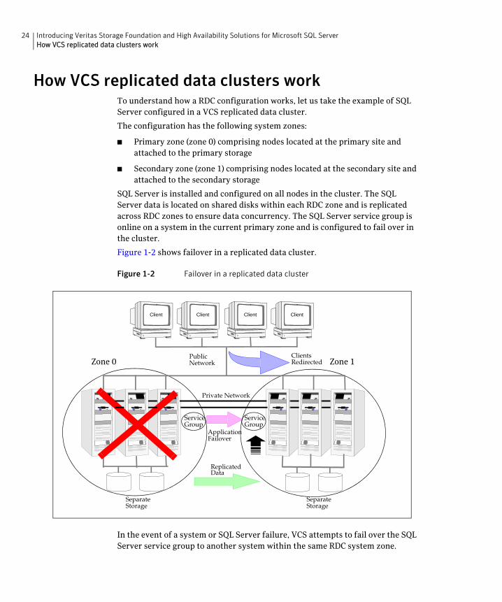
How VCS replicated data clusters workTo understand how a RDC configuration works, let us take the example of SQL Server configured in a VCS replicated data cluster.
The configuration has the following system zones:
■ Primary zone (zone 0) comprising nodes located at the primary site and attached to the primary storage
■ Secondary zone (zone 1) comprising nodes located at the secondary site and attached to the secondary storage
SQL Server is installed and configured on all nodes in the cluster. The SQL Server data is located on shared disks within each RDC zone and is replicated across RDC zones to ensure data concurrency. The SQL Server service group is online on a system in the current primary zone and is configured to fail over in the cluster.
Figure 1-2 shows failover in a replicated data cluster.
Figure 1-2 Failover in a replicated data cluster
In the event of a system or SQL Server failure, VCS attempts to fail over the SQL Server service group to another system within the same RDC system zone.
PublicNetwork
SeparateStorage
SeparateStorage
Client Client Client Client
ReplicatedData
ClientsRedirected
ApplicationFailover
ServiceGroup
Service Group
Zone 0 Zone 1
Private Network
25Introducing Veritas Storage Foundation and High Availability Solutions for Microsoft SQL ServerAbout disaster recovery
However, in the event that VCS fails to find a failover target node within the primary zone, VCS switches the service group to a node in the current secondary system zone (zone 1). VCS also redirects clients once the application is online on the new location.
About disaster recoveryWide area disaster recovery (DR) provides the ultimate protection for data and applications in the event of a disaster. If a disaster affects a local or metropolitan area, data and critical services are failed over to a site hundreds or thousands of miles away. Veritas Storage Foundation HA for Windows (SFW HA) provides the capability for implementing disaster recovery.
A disaster recovery (DR) solution is a series of procedures which you can use to safely and efficiently restore application user data and services in the event of a catastrophic failure. A typical DR solution requires that you have a source or primary site and a destination or secondary site. The user application data on the primary site is replicated to the secondary site. The cluster on the primary site provides data and services during normal operations. In the event of a disaster at the primary site and failure of the cluster, the secondary site provides the data and services.
Information about the disaster recovery solution for SQL Server includes procedures for installing, configuring, and testing clustered and replicated Microsoft SQL Server environments for disaster recovery using SFW HA.
What you can do with a disaster recovery solutionA DR solution is vital for businesses that rely on the availability of data.
A well-designed DR solution prepares a business for unexpected disasters and provides the following benefits in a DR situation:
■ Minimizes economic loss due to the unavailability or loss of data.
■ Provides a plan for the safe and orderly recovery of data in the event of a disaster.
■ Ensures safe and efficient recovery of data and services.
■ Minimizes any decision making during DR.
■ Reduces the reliance on key individuals.
Strategically planning a DR solution provides businesses with affordable ways to meet their service level agreements, comply with government regulations, and minimize their business risks.
26 Introducing Veritas Storage Foundation and High Availability Solutions for Microsoft SQL ServerWhat must be protected in an SQL Server environment
What must be protected in an SQL Server environment
The following components of a SQL Server environment must be protected in the event of a disaster:
Running SQL Server in an active-active clustered environment
SQL Server allows multiple independent instances of SQL Server to run on a single machine. Using this feature, the VCS database agent for Microsoft SQL Server supports SQL Server in an active-active environment by allowing a node to run as many instances as supported by SQL. A SQL Server instance can fail over to any of the other configured nodes that are part of the service group’s system list.
You can choose an active-active SQL Server configuration where several instances are intended to run on a single node. However, remember that you
User Databases The most critical component in any SQL Server implementation is the user data that is stored in user-defined databases.
Logins Logins allow clients to connect to SQL Server and execute queries on user data. Logins are stored in the master database and each of the user-defined databases.
Jobs Jobs are a set of scheduled tasks that maintain SQL Server databases. The job configuration is stored in the msdb system database
Alerts Alerts are actions that are taken when a specific event occurs. They are used to respond to and correct errors that occur in SQL Server. The alert configuration is stored in the msdb system database.
Operators Operators are contacts that address problems occurring in SQL Server. They are notified in the event of errors. The operator configuration is stored in the msdb system database.
Extended Stored Procedures
Extended stored procedures are external routines that are called from within SQL Server. They are typically stored in DLL files on the file system.
Other Server Extensions
SQL Server is a very flexible database engine and it is possible to extend its functionality in several ways. These extensions are also important to the operation of the SQL Server.
27Introducing Veritas Storage Foundation and High Availability Solutions for Microsoft SQL ServerTypical SQL Server configuration in a VCS cluster
must configure the failover nodes such that a single node can never host more instances than what is supported by SQL Server.
Refer to the Microsoft SQL Server documentation for more information about multiple instance support.
Typical SQL Server configuration in a VCS clusterA typical SQL Server configuration in a VCS cluster involves two cluster nodes accessing a shared storage. The SQL Server binaries are installed on the cluster nodes. The shared storage is used to store SQL Server data files and the MSDTC log files. The cluster nodes access the shared storage. The shared storage can be managed using SFW.
28 Introducing Veritas Storage Foundation and High Availability Solutions for Microsoft SQL ServerTypical SQL Server disaster recovery configuration
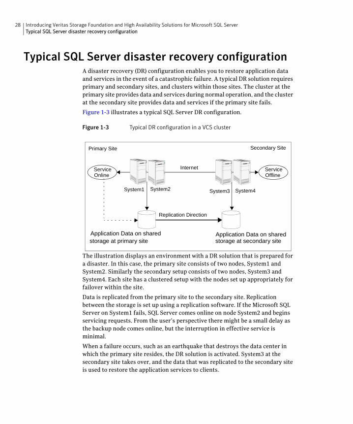
Typical SQL Server disaster recovery configurationA disaster recovery (DR) configuration enables you to restore application data and services in the event of a catastrophic failure. A typical DR solution requires primary and secondary sites, and clusters within those sites. The cluster at the primary site provides data and services during normal operation, and the cluster at the secondary site provides data and services if the primary site fails.
Figure 1-3 illustrates a typical SQL Server DR configuration.
Figure 1-3 Typical DR configuration in a VCS cluster
The illustration displays an environment with a DR solution that is prepared for a disaster. In this case, the primary site consists of two nodes, System1 and System2. Similarly the secondary setup consists of two nodes, System3 and System4. Each site has a clustered setup with the nodes set up appropriately for failover within the site.
Data is replicated from the primary site to the secondary site. Replication between the storage is set up using a replication software. If the Microsoft SQL Server on System1 fails, SQL Server comes online on node System2 and begins servicing requests. From the user’s perspective there might be a small delay as the backup node comes online, but the interruption in effective service is minimal.
When a failure occurs, such as an earthquake that destroys the data center in which the primary site resides, the DR solution is activated. System3 at the secondary site takes over, and the data that was replicated to the secondary site is used to restore the application services to clients.
Internet
Application Data on shared
Replication Direction
Primary Site Secondary Site
ServiceOnline
ServiceOffline
Application Data on sharedstorage at primary site
System1 System2 System3 System4
storage at secondary site
29Introducing Veritas Storage Foundation and High Availability Solutions for Microsoft SQL ServerWhere to get more information about Veritas Storage Foundation and High Availability Solutions for Microsoft SQL Server
Where to get more information about Veritas Storage Foundation and High Availability Solutions for Microsoft SQL Server
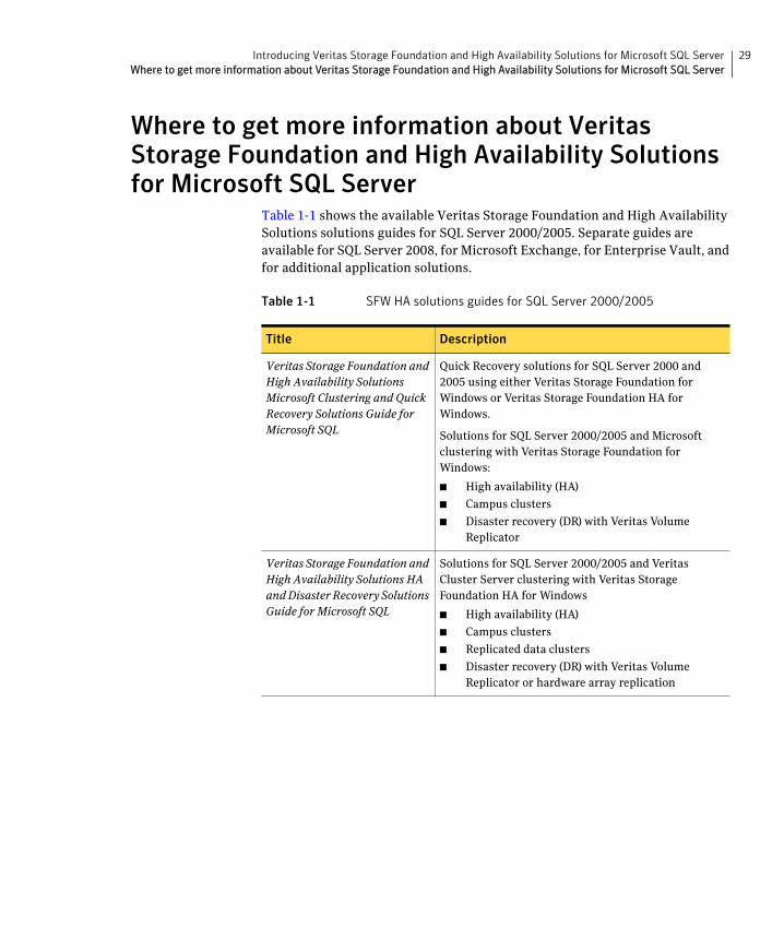
Table 1-1 shows the available Veritas Storage Foundation and High Availability Solutions solutions guides for SQL Server 2000/2005. Separate guides are available for SQL Server 2008, for Microsoft Exchange, for Enterprise Vault, and for additional application solutions.
Table 1-1 SFW HA solutions guides for SQL Server 2000/2005
Title Description
Veritas Storage Foundation and High Availability Solutions Microsoft Clustering and Quick Recovery Solutions Guide for Microsoft SQL
Quick Recovery solutions for SQL Server 2000 and 2005 using either Veritas Storage Foundation for Windows or Veritas Storage Foundation HA for Windows.
Solutions for SQL Server 2000/2005 and Microsoft clustering with Veritas Storage Foundation for Windows:
■ High availability (HA)
■ Campus clusters
■ Disaster recovery (DR) with Veritas Volume Replicator
Veritas Storage Foundation and High Availability Solutions HA and Disaster Recovery Solutions Guide for Microsoft SQL
Solutions for SQL Server 2000/2005 and Veritas Cluster Server clustering with Veritas Storage Foundation HA for Windows
■ High availability (HA)
■ Campus clusters
■ Replicated data clusters
■ Disaster recovery (DR) with Veritas Volume Replicator or hardware array replication

30 Introducing Veritas Storage Foundation and High Availability Solutions for Microsoft SQL ServerWhere to get more information about Veritas Storage Foundation and High Availability Solutions for Microsoft SQL Server
Section
2 Configuration WorkflowsThis section contains the following chapters:
■ Configuration workflows for SQL Server
■ Using the Solutions Configuration Center

32
Chapter
2Configuration workflows for SQL Server
This chapter contains the following topics:
■ About using the workflow tables
■ High availability (HA) configuration (New Server)
■ High availability (HA) configuration (Existing Server)
■ Tasks for configuring MSDTC for high availability
■ VCS campus cluster configuration
■ VCS Replicated Data Cluster configuration
■ Disaster recovery configuration
About using the workflow tablesConfiguring a high availability or a disaster recovery environment involves a series of tasks such as evaluating the requirements, configuring the storage, installing and configuring VCS, installing and configuring the application, and so on. A configuration workflow table provides high level description of all the required tasks, with links to the topics that describe these tasks in detail.
Separate workflow tables are provided for HA, campus cluster, Replicated Data Cluster and DR configurations. Depending on the required high availability configuration, use the appropriate workflow table as a guideline to perform the installation and configuration.
Symantec recommends using the Solutions Configuration Center as a guide for installing and configuring SFW HA for SQL Server.
See “About the Solutions Configuration Center” on page 55.

34 Configuration workflows for SQL ServerAbout using the workflow tables
The workflow tables are organized to follow the workflows in the Solutions Configuration Center.
For example, in using the Solutions Configuration Center to set up a site for disaster recovery, you first follow the steps under High Availability (HA) Configuration and then continue with the steps under Disaster Recovery Configuration. Likewise, in this guide, you first refer to the High Availability workflow to set up high availability. You then continue with the appropriate workflow, either Replicated Data Cluster, campus cluster, or disaster recovery, for any additional solution that you want to implement.
35Configuration workflows for SQL ServerHigh availability (HA) configuration (New Server)
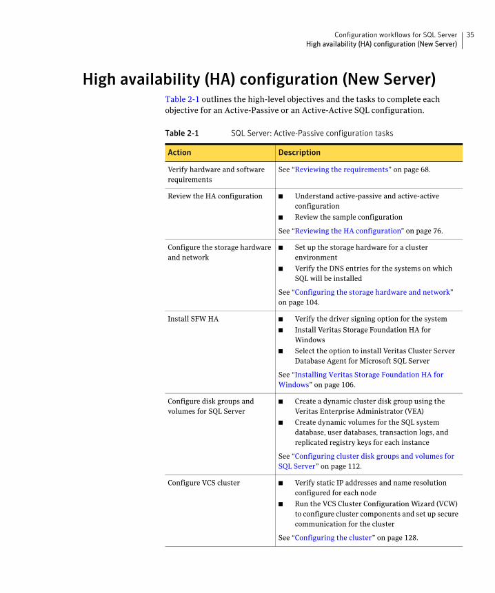
High availability (HA) configuration (New Server)Table 2-1 outlines the high-level objectives and the tasks to complete each objective for an Active-Passive or an Active-Active SQL configuration.
Table 2-1 SQL Server: Active-Passive configuration tasks
Action Description
Verify hardware and software requirements
See “Reviewing the requirements” on page 68.
Review the HA configuration ■ Understand active-passive and active-active configuration
■ Review the sample configuration
See “Reviewing the HA configuration” on page 76.
Configure the storage hardware and network
■ Set up the storage hardware for a cluster environment
■ Verify the DNS entries for the systems on which SQL will be installed
See “Configuring the storage hardware and network” on page 104.
Install SFW HA ■ Verify the driver signing option for the system
■ Install Veritas Storage Foundation HA for Windows
■ Select the option to install Veritas Cluster Server Database Agent for Microsoft SQL Server
See “Installing Veritas Storage Foundation HA for Windows” on page 106.
Configure disk groups and volumes for SQL Server
■ Create a dynamic cluster disk group using the Veritas Enterprise Administrator (VEA)
■ Create dynamic volumes for the SQL system database, user databases, transaction logs, and replicated registry keys for each instance
See “Configuring cluster disk groups and volumes for SQL Server” on page 112.
Configure VCS cluster ■ Verify static IP addresses and name resolution configured for each node
■ Run the VCS Cluster Configuration Wizard (VCW) to configure cluster components and set up secure communication for the cluster
See “Configuring the cluster” on page 128.
36 Configuration workflows for SQL ServerHigh availability (HA) configuration (New Server)
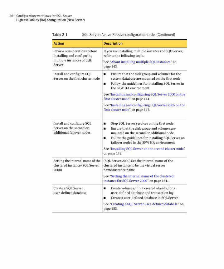
Review considerations before installing and configuring multiple instances of SQL Server
If you are installing multiple instances of SQL Server, refer to the following topic.
See “About installing multiple SQL instances” on page 143.
Install and configure SQL Server on the first cluster node
■ Ensure that the disk group and volumes for the system database are mounted on the first node
■ Follow the guidelines for installing SQL Server in the SFW HA environment
See “Installing and configuring SQL Server 2000 on the first cluster node” on page 144.
See “Installing and configuring SQL Server 2005 on the first cluster node” on page 147.
Install and configure SQL Server on the second or additional failover nodes
■ Stop SQL Server services on the first node
■ Ensure that the disk group and volumes are mounted on the second or additional node
■ Follow the guidelines for installing SQL Server on failover nodes in the SFW HA environment
See “Installing SQL Server on the second cluster node” on page 149.
Setting the internal name of the clustered instance (SQL Server 2000)
(SQL Server 2000) Set the internal name of the clustered instance to be the virtual server name\instance name
See “Setting the internal name of the clustered instance for SQL Server 2000” on page 151.
Create a SQL Server user-defined database
■ Create volumes, if not created already, for a user-defined database and transaction log
■ Create a user-defined database in SQL Server
See “Creating a SQL Server user-defined database” on page 153.
Table 2-1 SQL Server: Active-Passive configuration tasks (Continued)
Action Description
37Configuration workflows for SQL ServerHigh availability (HA) configuration (New Server)
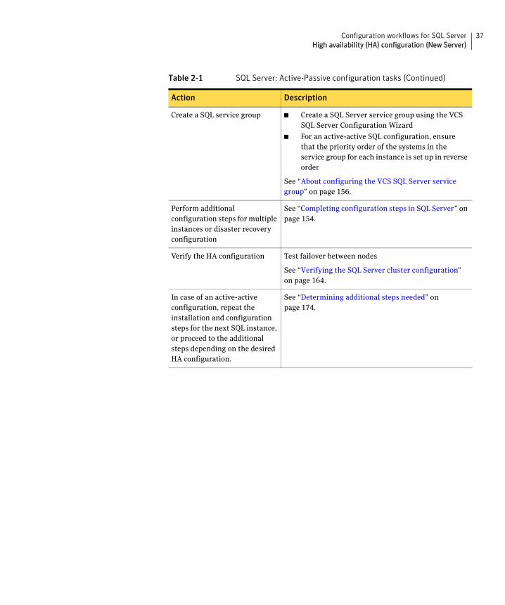
Create a SQL service group ■ Create a SQL Server service group using the VCS SQL Server Configuration Wizard
■ For an active-active SQL configuration, ensure that the priority order of the systems in the service group for each instance is set up in reverse order
See “About configuring the VCS SQL Server service group” on page 156.
Perform additional configuration steps for multiple instances or disaster recovery configuration
See “Completing configuration steps in SQL Server” on page 154.
Verify the HA configuration Test failover between nodes
See “Verifying the SQL Server cluster configuration” on page 164.
In case of an active-active configuration, repeat the installation and configuration steps for the next SQL instance, or proceed to the additional steps depending on the desired HA configuration.
See “Determining additional steps needed” on page 174.
Table 2-1 SQL Server: Active-Passive configuration tasks (Continued)
Action Description
38 Configuration workflows for SQL ServerHigh availability (HA) configuration (Existing Server)
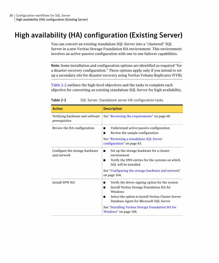
High availability (HA) configuration (Existing Server)You can convert an existing standalone SQL Server into a “clustered” SQL Server in a new Veritas Storage Foundation HA environment. This environment involves an active-passive configuration with one to one failover capabilities.
Note: Some installation and configuration options are identified as required “for a disaster recovery configuration.” These options apply only if you intend to set up a secondary site for disaster recovery using Veritas Volume Replicator (VVR).
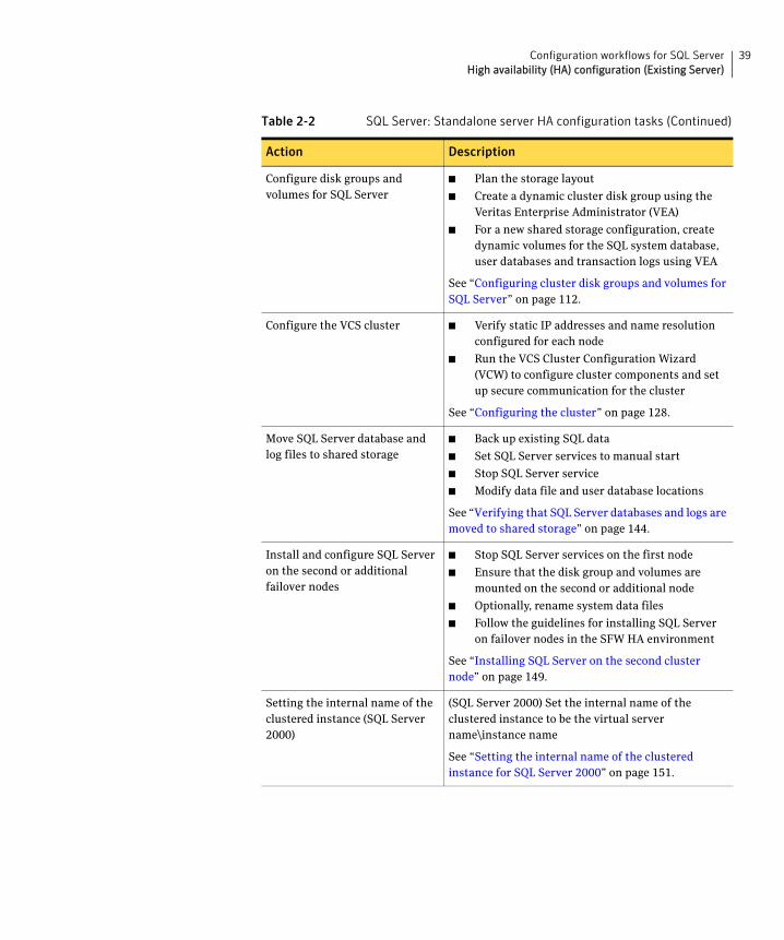
Table 2-2 outlines the high-level objectives and the tasks to complete each objective for converting an existing standalone SQL Server for high availability.
Table 2-2 SQL Server: Standalone server HA configuration tasks
Action Description
Verifying hardware and software prerequisites
See “Reviewing the requirements” on page 68.
Review the HA configuration ■ Understand active-passive configuration
■ Review the sample configuration
See “Reviewing a standalone SQL Server configuration” on page 83.
Configure the storage hardware and network
■ Set up the storage hardware for a cluster environment
■ Verify the DNS entries for the systems on which SQL will be installed
See “Configuring the storage hardware and network” on page 104.
Install SFW HA ■ Verify the driver signing option for the system
■ Install Veritas Storage Foundation HA for Windows
■ Select the option to install Veritas Cluster Server Database Agent for Microsoft SQL Server
See “Installing Veritas Storage Foundation HA for Windows” on page 106.
39Configuration workflows for SQL ServerHigh availability (HA) configuration (Existing Server)
Configure disk groups and volumes for SQL Server
■ Plan the storage layout
■ Create a dynamic cluster disk group using the Veritas Enterprise Administrator (VEA)
■ For a new shared storage configuration, create dynamic volumes for the SQL system database, user databases and transaction logs using VEA
See “Configuring cluster disk groups and volumes for SQL Server” on page 112.
Configure the VCS cluster ■ Verify static IP addresses and name resolution configured for each node
■ Run the VCS Cluster Configuration Wizard (VCW) to configure cluster components and set up secure communication for the cluster
See “Configuring the cluster” on page 128.
Move SQL Server database and log files to shared storage
■ Back up existing SQL data
■ Set SQL Server services to manual start
■ Stop SQL Server service
■ Modify data file and user database locations
See “Verifying that SQL Server databases and logs are moved to shared storage” on page 144.
Install and configure SQL Server on the second or additional failover nodes
■ Stop SQL Server services on the first node
■ Ensure that the disk group and volumes are mounted on the second or additional node
■ Optionally, rename system data files
■ Follow the guidelines for installing SQL Server on failover nodes in the SFW HA environment
See “Installing SQL Server on the second cluster node” on page 149.
Setting the internal name of the clustered instance (SQL Server 2000)
(SQL Server 2000) Set the internal name of the clustered instance to be the virtual server name\instance name
See “Setting the internal name of the clustered instance for SQL Server 2000” on page 151.
Table 2-2 SQL Server: Standalone server HA configuration tasks (Continued)
Action Description
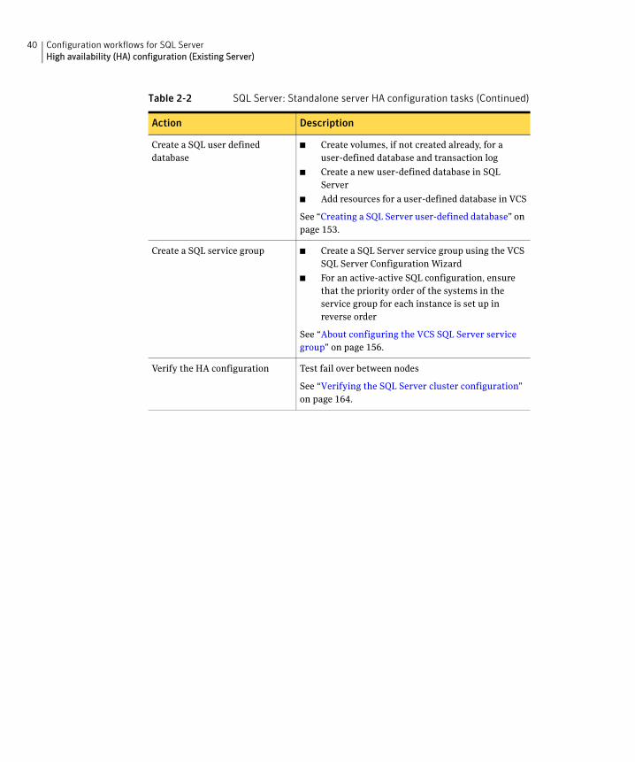
40 Configuration workflows for SQL ServerHigh availability (HA) configuration (Existing Server)
Create a SQL user defined database
■ Create volumes, if not created already, for a user-defined database and transaction log
■ Create a new user-defined database in SQL Server
■ Add resources for a user-defined database in VCS
See “Creating a SQL Server user-defined database” on page 153.
Create a SQL service group ■ Create a SQL Server service group using the VCS SQL Server Configuration Wizard
■ For an active-active SQL configuration, ensure that the priority order of the systems in the service group for each instance is set up in reverse order
See “About configuring the VCS SQL Server service group” on page 156.
Verify the HA configuration Test fail over between nodes
See “Verifying the SQL Server cluster configuration” on page 164.
Table 2-2 SQL Server: Standalone server HA configuration tasks (Continued)
Action Description
41Configuration workflows for SQL ServerTasks for configuring MSDTC for high availability
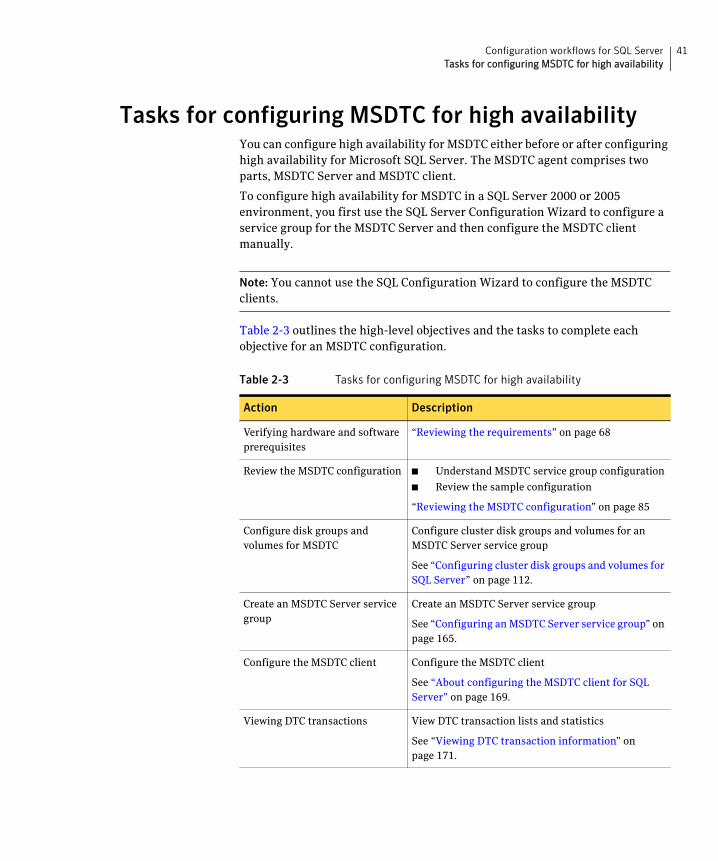
Tasks for configuring MSDTC for high availabilityYou can configure high availability for MSDTC either before or after configuring high availability for Microsoft SQL Server. The MSDTC agent comprises two parts, MSDTC Server and MSDTC client.
To configure high availability for MSDTC in a SQL Server 2000 or 2005 environment, you first use the SQL Server Configuration Wizard to configure a service group for the MSDTC Server and then configure the MSDTC client manually.
Note: You cannot use the SQL Configuration Wizard to configure the MSDTC clients.
Table 2-3 outlines the high-level objectives and the tasks to complete each objective for an MSDTC configuration.
Table 2-3 Tasks for configuring MSDTC for high availability
Action Description
Verifying hardware and software prerequisites
“Reviewing the requirements” on page 68
Review the MSDTC configuration ■ Understand MSDTC service group configuration
■ Review the sample configuration
“Reviewing the MSDTC configuration” on page 85
Configure disk groups and volumes for MSDTC
Configure cluster disk groups and volumes for an MSDTC Server service group
See “Configuring cluster disk groups and volumes for SQL Server” on page 112.
Create an MSDTC Server service group
Create an MSDTC Server service group
See “Configuring an MSDTC Server service group” on page 165.
Configure the MSDTC client Configure the MSDTC client
See “About configuring the MSDTC client for SQL Server” on page 169.
Viewing DTC transactions View DTC transaction lists and statistics
See “Viewing DTC transaction information” on page 171.
42 Configuration workflows for SQL ServerVCS campus cluster configuration
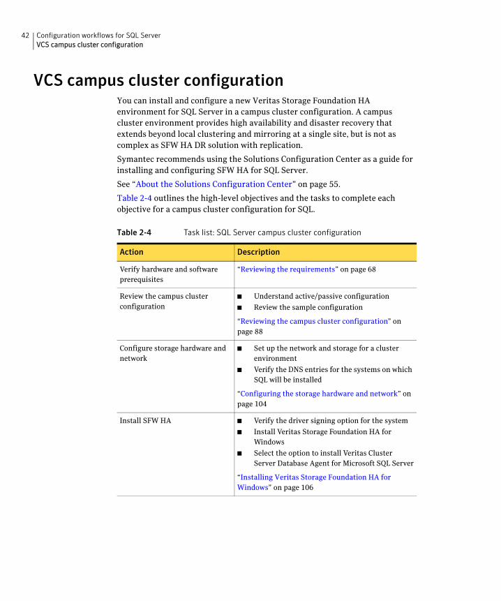
VCS campus cluster configurationYou can install and configure a new Veritas Storage Foundation HA environment for SQL Server in a campus cluster configuration. A campus cluster environment provides high availability and disaster recovery that extends beyond local clustering and mirroring at a single site, but is not as complex as SFW HA DR solution with replication.
Symantec recommends using the Solutions Configuration Center as a guide for installing and configuring SFW HA for SQL Server.
See “About the Solutions Configuration Center” on page 55.
Table 2-4 outlines the high-level objectives and the tasks to complete each objective for a campus cluster configuration for SQL.
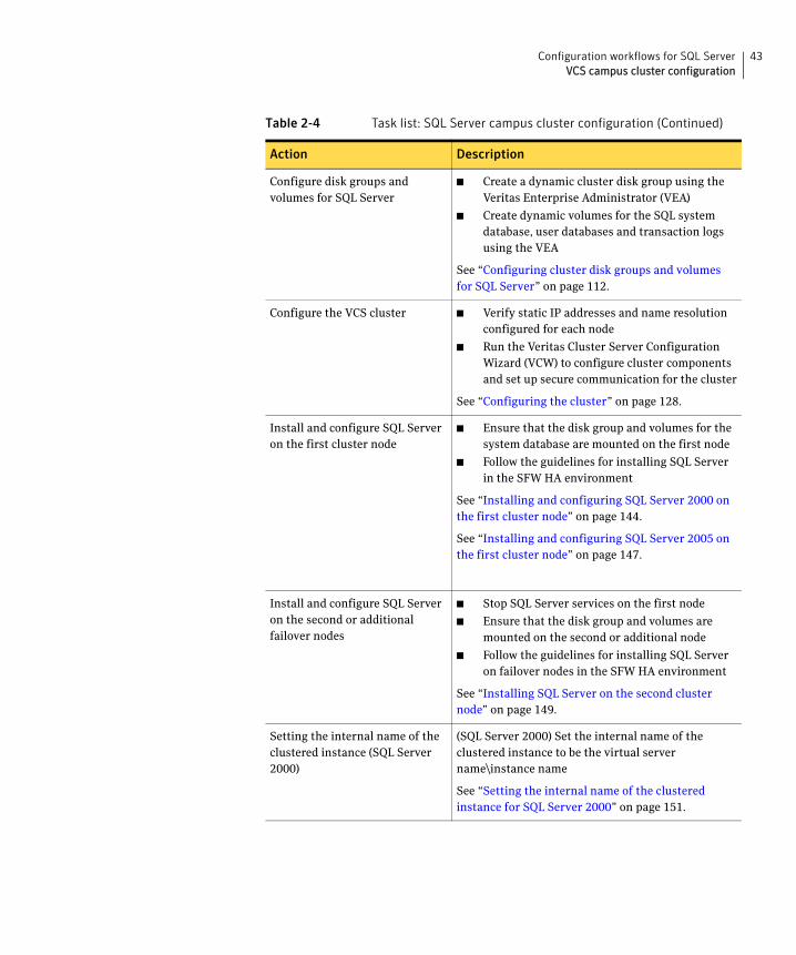
Table 2-4 Task list: SQL Server campus cluster configuration
Action Description
Verify hardware and software prerequisites
“Reviewing the requirements” on page 68
Review the campus cluster configuration
■ Understand active/passive configuration
■ Review the sample configuration
“Reviewing the campus cluster configuration” on page 88
Configure storage hardware and network
■ Set up the network and storage for a cluster environment
■ Verify the DNS entries for the systems on which SQL will be installed
“Configuring the storage hardware and network” on page 104
Install SFW HA ■ Verify the driver signing option for the system
■ Install Veritas Storage Foundation HA for Windows
■ Select the option to install Veritas Cluster Server Database Agent for Microsoft SQL Server
“Installing Veritas Storage Foundation HA for Windows” on page 106
43Configuration workflows for SQL ServerVCS campus cluster configuration
Configure disk groups and volumes for SQL Server
■ Create a dynamic cluster disk group using the Veritas Enterprise Administrator (VEA)
■ Create dynamic volumes for the SQL system database, user databases and transaction logs using the VEA
See “Configuring cluster disk groups and volumes for SQL Server” on page 112.
Configure the VCS cluster ■ Verify static IP addresses and name resolution configured for each node
■ Run the Veritas Cluster Server Configuration Wizard (VCW) to configure cluster components and set up secure communication for the cluster
See “Configuring the cluster” on page 128.
Install and configure SQL Server on the first cluster node
■ Ensure that the disk group and volumes for the system database are mounted on the first node
■ Follow the guidelines for installing SQL Server in the SFW HA environment
See “Installing and configuring SQL Server 2000 on the first cluster node” on page 144.
See “Installing and configuring SQL Server 2005 on the first cluster node” on page 147.
Install and configure SQL Server on the second or additional failover nodes
■ Stop SQL Server services on the first node
■ Ensure that the disk group and volumes are mounted on the second or additional node
■ Follow the guidelines for installing SQL Server on failover nodes in the SFW HA environment
See “Installing SQL Server on the second cluster node” on page 149.
Setting the internal name of the clustered instance (SQL Server 2000)
(SQL Server 2000) Set the internal name of the clustered instance to be the virtual server name\instance name
See “Setting the internal name of the clustered instance for SQL Server 2000” on page 151.
Table 2-4 Task list: SQL Server campus cluster configuration (Continued)
Action Description
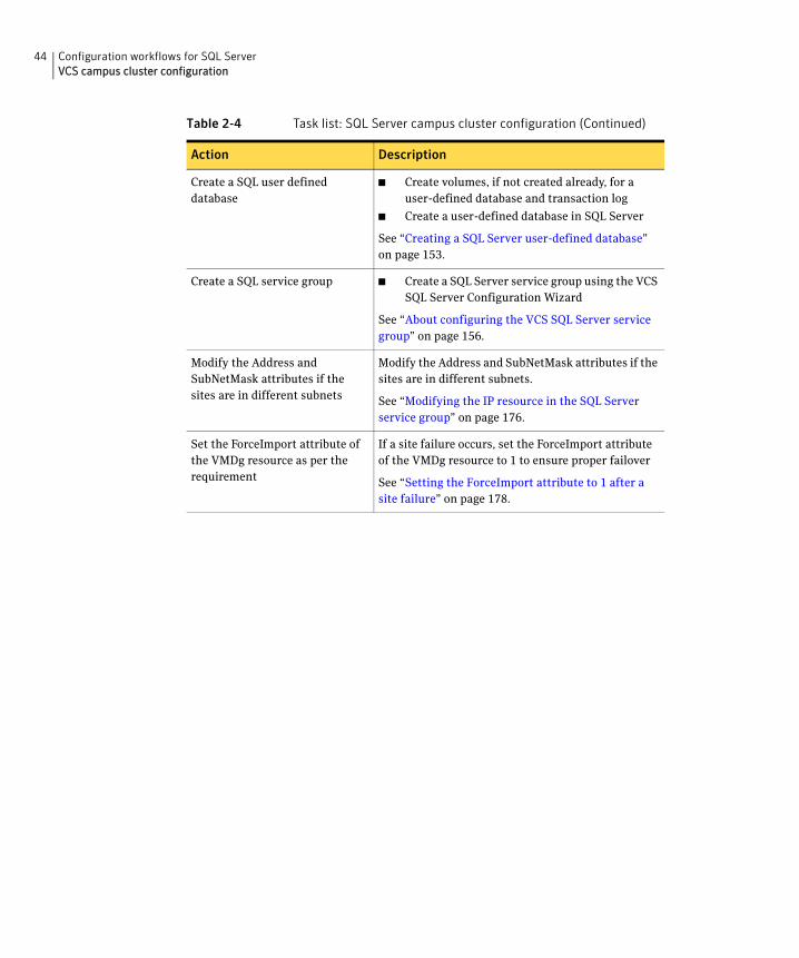
44 Configuration workflows for SQL ServerVCS campus cluster configuration
Create a SQL user defined database
■ Create volumes, if not created already, for a user-defined database and transaction log
■ Create a user-defined database in SQL Server
See “Creating a SQL Server user-defined database” on page 153.
Create a SQL service group ■ Create a SQL Server service group using the VCS SQL Server Configuration Wizard
See “About configuring the VCS SQL Server service group” on page 156.
Modify the Address and SubNetMask attributes if the sites are in different subnets
Modify the Address and SubNetMask attributes if the sites are in different subnets.
See “Modifying the IP resource in the SQL Server service group” on page 176.
Set the ForceImport attribute of the VMDg resource as per the requirement
If a site failure occurs, set the ForceImport attribute of the VMDg resource to 1 to ensure proper failover
See “Setting the ForceImport attribute to 1 after a site failure” on page 178.
Table 2-4 Task list: SQL Server campus cluster configuration (Continued)
Action Description
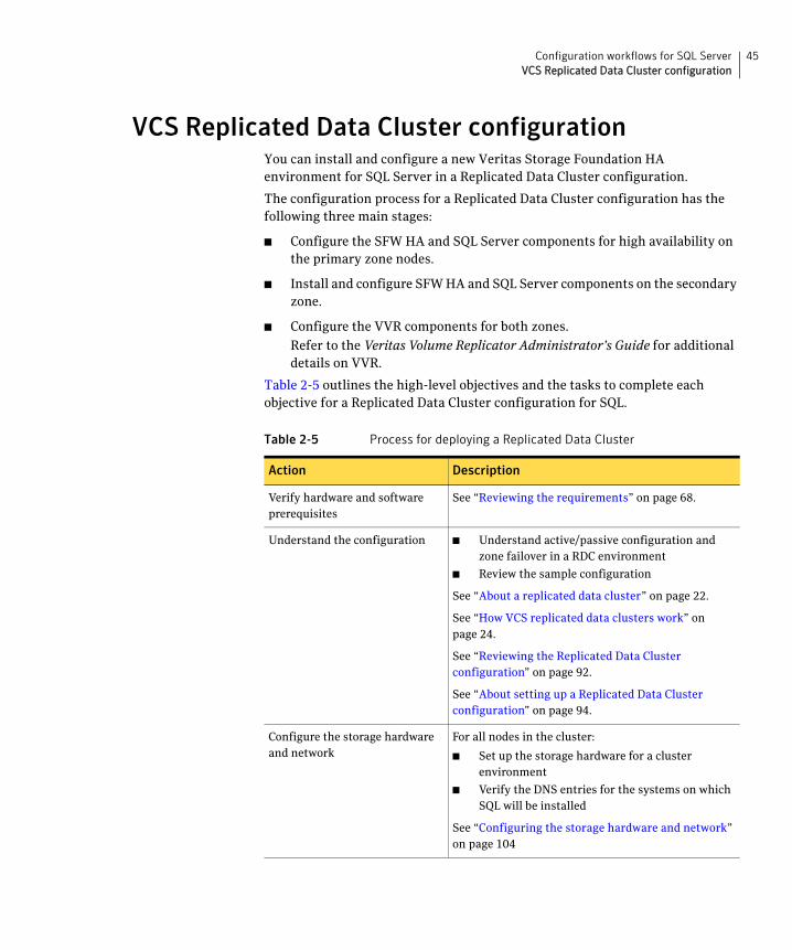
45Configuration workflows for SQL ServerVCS Replicated Data Cluster configuration
VCS Replicated Data Cluster configurationYou can install and configure a new Veritas Storage Foundation HA environment for SQL Server in a Replicated Data Cluster configuration.
The configuration process for a Replicated Data Cluster configuration has the following three main stages:
■ Configure the SFW HA and SQL Server components for high availability on the primary zone nodes.
■ Install and configure SFW HA and SQL Server components on the secondary zone.
■ Configure the VVR components for both zones.
Refer to the Veritas Volume Replicator Administrator’s Guide for additional details on VVR.
Table 2-5 outlines the high-level objectives and the tasks to complete each objective for a Replicated Data Cluster configuration for SQL.
Table 2-5 Process for deploying a Replicated Data Cluster
Action Description
Verify hardware and software prerequisites
See “Reviewing the requirements” on page 68.
Understand the configuration ■ Understand active/passive configuration and zone failover in a RDC environment
■ Review the sample configuration
See “About a replicated data cluster” on page 22.
See “How VCS replicated data clusters work” on page 24.
See “Reviewing the Replicated Data Cluster configuration” on page 92.
See “About setting up a Replicated Data Cluster configuration” on page 94.
Configure the storage hardware and network
For all nodes in the cluster:
■ Set up the storage hardware for a cluster environment
■ Verify the DNS entries for the systems on which SQL will be installed
See “Configuring the storage hardware and network” on page 104
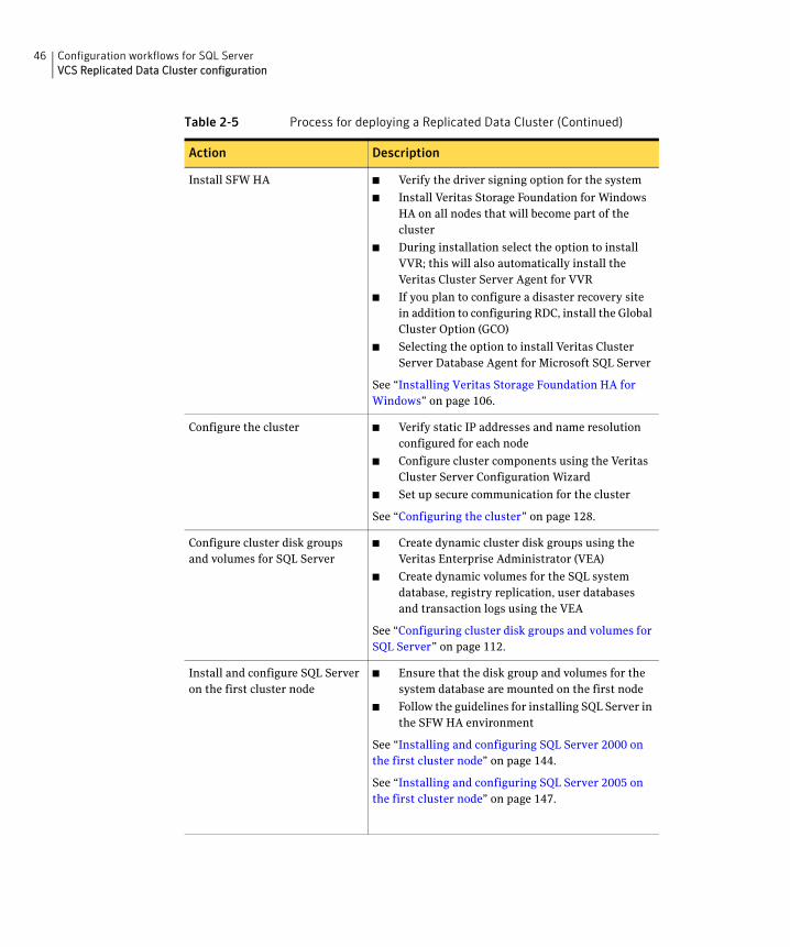
46 Configuration workflows for SQL ServerVCS Replicated Data Cluster configuration
Install SFW HA ■ Verify the driver signing option for the system
■ Install Veritas Storage Foundation for Windows HA on all nodes that will become part of the cluster
■ During installation select the option to install VVR; this will also automatically install the Veritas Cluster Server Agent for VVR
■ If you plan to configure a disaster recovery site in addition to configuring RDC, install the Global Cluster Option (GCO)
■ Selecting the option to install Veritas Cluster Server Database Agent for Microsoft SQL Server
See “Installing Veritas Storage Foundation HA for Windows” on page 106.
Configure the cluster ■ Verify static IP addresses and name resolution configured for each node
■ Configure cluster components using the Veritas Cluster Server Configuration Wizard
■ Set up secure communication for the cluster
See “Configuring the cluster” on page 128.
Configure cluster disk groups and volumes for SQL Server
■ Create dynamic cluster disk groups using the Veritas Enterprise Administrator (VEA)
■ Create dynamic volumes for the SQL system database, registry replication, user databases and transaction logs using the VEA
See “Configuring cluster disk groups and volumes for SQL Server” on page 112.
Install and configure SQL Server on the first cluster node
■ Ensure that the disk group and volumes for the system database are mounted on the first node
■ Follow the guidelines for installing SQL Server in the SFW HA environment
See “Installing and configuring SQL Server 2000 on the first cluster node” on page 144.
See “Installing and configuring SQL Server 2005 on the first cluster node” on page 147.
Table 2-5 Process for deploying a Replicated Data Cluster (Continued)
Action Description
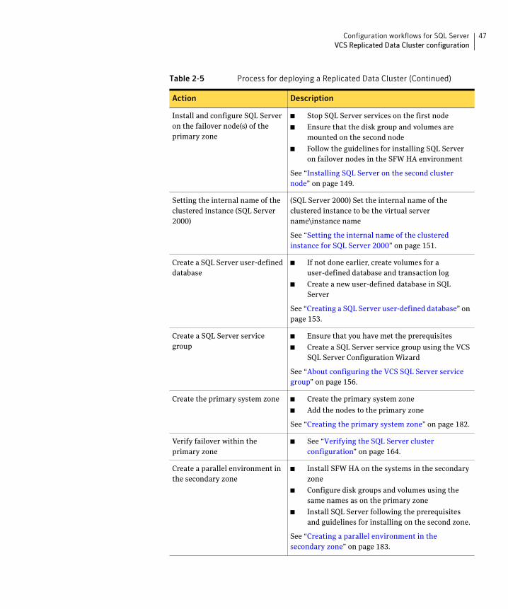
47Configuration workflows for SQL ServerVCS Replicated Data Cluster configuration
Install and configure SQL Server on the failover node(s) of the primary zone
■ Stop SQL Server services on the first node
■ Ensure that the disk group and volumes are mounted on the second node
■ Follow the guidelines for installing SQL Server on failover nodes in the SFW HA environment
See “Installing SQL Server on the second cluster node” on page 149.
Setting the internal name of the clustered instance (SQL Server 2000)
(SQL Server 2000) Set the internal name of the clustered instance to be the virtual server name\instance name
See “Setting the internal name of the clustered instance for SQL Server 2000” on page 151.
Create a SQL Server user-defined database
■ If not done earlier, create volumes for a user-defined database and transaction log
■ Create a new user-defined database in SQL Server
See “Creating a SQL Server user-defined database” on page 153.
Create a SQL Server service group
■ Ensure that you have met the prerequisites
■ Create a SQL Server service group using the VCS SQL Server Configuration Wizard
See “About configuring the VCS SQL Server service group” on page 156.
Create the primary system zone ■ Create the primary system zone
■ Add the nodes to the primary zone
See “Creating the primary system zone” on page 182.
Verify failover within the primary zone
■ See “Verifying the SQL Server cluster configuration” on page 164.
Create a parallel environment in the secondary zone
■ Install SFW HA on the systems in the secondary zone
■ Configure disk groups and volumes using the same names as on the primary zone
■ Install SQL Server following the prerequisites and guidelines for installing on the second zone.
See “Creating a parallel environment in the secondary zone” on page 183.
Table 2-5 Process for deploying a Replicated Data Cluster (Continued)
Action Description
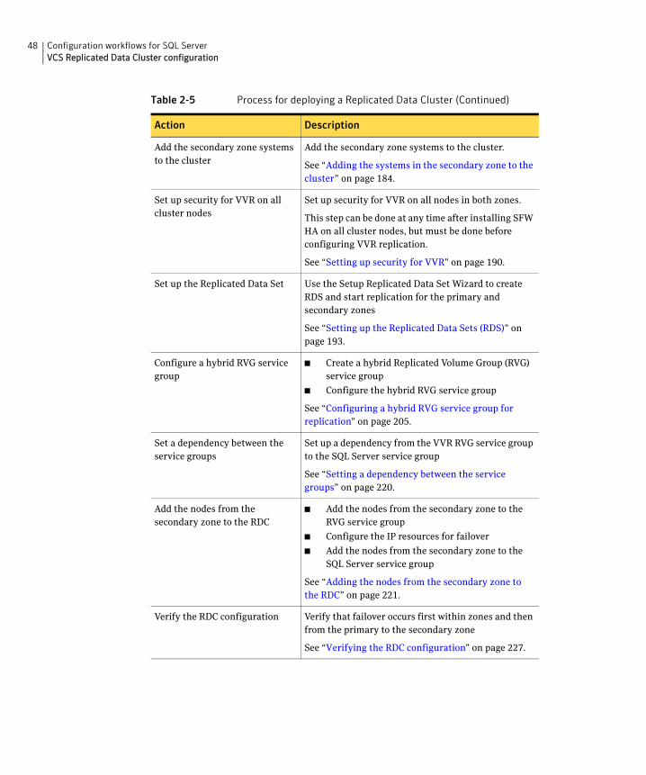
48 Configuration workflows for SQL ServerVCS Replicated Data Cluster configuration
Add the secondary zone systems to the cluster
Add the secondary zone systems to the cluster.
See “Adding the systems in the secondary zone to the cluster” on page 184.
Set up security for VVR on all cluster nodes
Set up security for VVR on all nodes in both zones.
This step can be done at any time after installing SFW HA on all cluster nodes, but must be done before configuring VVR replication.
See “Setting up security for VVR” on page 190.
Set up the Replicated Data Set Use the Setup Replicated Data Set Wizard to create RDS and start replication for the primary and secondary zones
See “Setting up the Replicated Data Sets (RDS)” on page 193.
Configure a hybrid RVG service group
■ Create a hybrid Replicated Volume Group (RVG) service group
■ Configure the hybrid RVG service group
See “Configuring a hybrid RVG service group for replication” on page 205.
Set a dependency between the service groups
Set up a dependency from the VVR RVG service group to the SQL Server service group
See “Setting a dependency between the service groups” on page 220.
Add the nodes from the secondary zone to the RDC
■ Add the nodes from the secondary zone to the RVG service group
■ Configure the IP resources for failover
■ Add the nodes from the secondary zone to the SQL Server service group
See “Adding the nodes from the secondary zone to the RDC” on page 221.
Verify the RDC configuration Verify that failover occurs first within zones and then from the primary to the secondary zone
See “Verifying the RDC configuration” on page 227.
Table 2-5 Process for deploying a Replicated Data Cluster (Continued)
Action Description
49Configuration workflows for SQL ServerDisaster recovery configuration
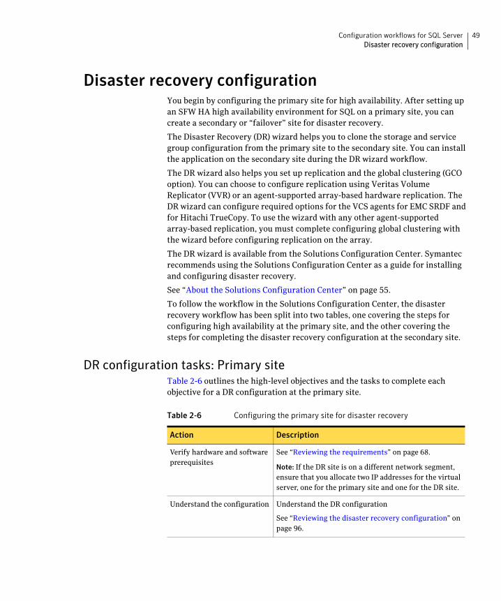
Disaster recovery configurationYou begin by configuring the primary site for high availability. After setting up an SFW HA high availability environment for SQL on a primary site, you can create a secondary or “failover” site for disaster recovery.
The Disaster Recovery (DR) wizard helps you to clone the storage and service group configuration from the primary site to the secondary site. You can install the application on the secondary site during the DR wizard workflow.
The DR wizard also helps you set up replication and the global clustering (GCO option). You can choose to configure replication using Veritas Volume Replicator (VVR) or an agent-supported array-based hardware replication. The DR wizard can configure required options for the VCS agents for EMC SRDF and for Hitachi TrueCopy. To use the wizard with any other agent-supported array-based replication, you must complete configuring global clustering with the wizard before configuring replication on the array.
The DR wizard is available from the Solutions Configuration Center. Symantec recommends using the Solutions Configuration Center as a guide for installing and configuring disaster recovery.
See “About the Solutions Configuration Center” on page 55.
To follow the workflow in the Solutions Configuration Center, the disaster recovery workflow has been split into two tables, one covering the steps for configuring high availability at the primary site, and the other covering the steps for completing the disaster recovery configuration at the secondary site.
DR configuration tasks: Primary siteTable 2-6 outlines the high-level objectives and the tasks to complete each objective for a DR configuration at the primary site.
Table 2-6 Configuring the primary site for disaster recovery
Action Description
Verify hardware and software prerequisites
See “Reviewing the requirements” on page 68.
Note: If the DR site is on a different network segment, ensure that you allocate two IP addresses for the virtual server, one for the primary site and one for the DR site.
Understand the configuration Understand the DR configuration
See “Reviewing the disaster recovery configuration” on page 96.
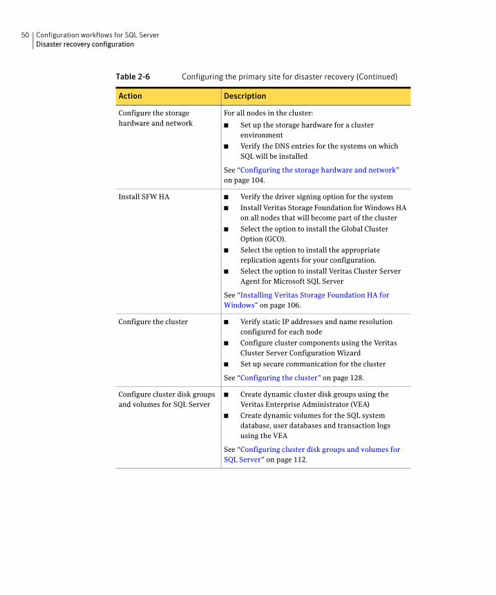
50 Configuration workflows for SQL ServerDisaster recovery configuration
Configure the storage hardware and network
For all nodes in the cluster:
■ Set up the storage hardware for a cluster environment
■ Verify the DNS entries for the systems on which SQL will be installed
See “Configuring the storage hardware and network” on page 104.
Install SFW HA ■ Verify the driver signing option for the system
■ Install Veritas Storage Foundation for Windows HA on all nodes that will become part of the cluster
■ Select the option to install the Global Cluster Option (GCO).
■ Select the option to install the appropriate replication agents for your configuration.
■ Select the option to install Veritas Cluster Server Agent for Microsoft SQL Server
See “Installing Veritas Storage Foundation HA for Windows” on page 106.
Configure the cluster ■ Verify static IP addresses and name resolution configured for each node
■ Configure cluster components using the Veritas Cluster Server Configuration Wizard
■ Set up secure communication for the cluster
See “Configuring the cluster” on page 128.
Configure cluster disk groups and volumes for SQL Server
■ Create dynamic cluster disk groups using the Veritas Enterprise Administrator (VEA)
■ Create dynamic volumes for the SQL system database, user databases and transaction logs using the VEA
See “Configuring cluster disk groups and volumes for SQL Server” on page 112.
Table 2-6 Configuring the primary site for disaster recovery (Continued)
Action Description
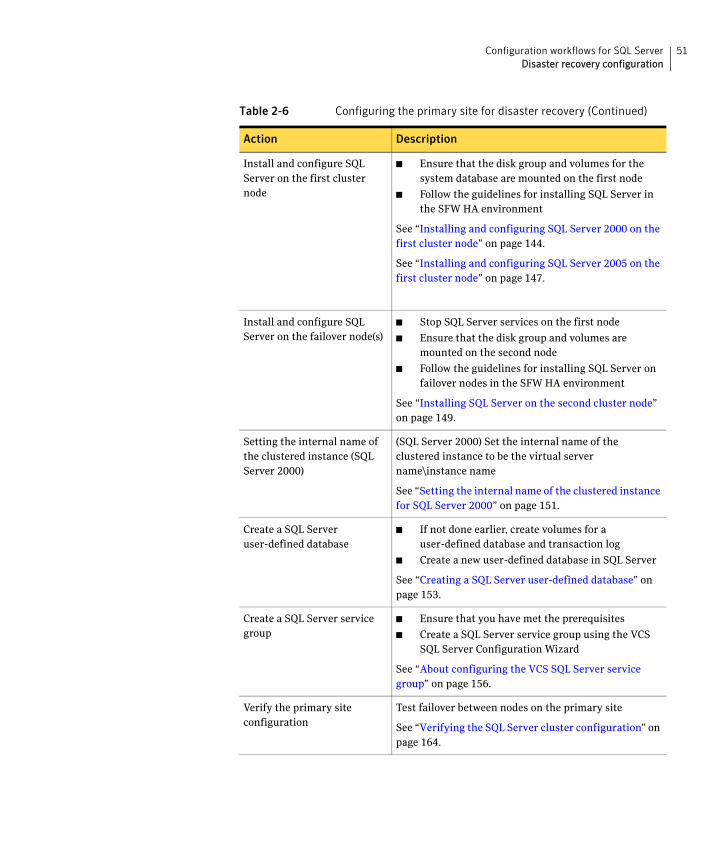
51Configuration workflows for SQL ServerDisaster recovery configuration
Install and configure SQL Server on the first cluster node
■ Ensure that the disk group and volumes for the system database are mounted on the first node
■ Follow the guidelines for installing SQL Server in the SFW HA environment
See “Installing and configuring SQL Server 2000 on the first cluster node” on page 144.
See “Installing and configuring SQL Server 2005 on the first cluster node” on page 147.
Install and configure SQL Server on the failover node(s)
■ Stop SQL Server services on the first node
■ Ensure that the disk group and volumes are mounted on the second node
■ Follow the guidelines for installing SQL Server on failover nodes in the SFW HA environment
See “Installing SQL Server on the second cluster node” on page 149.
Setting the internal name of the clustered instance (SQL Server 2000)
(SQL Server 2000) Set the internal name of the clustered instance to be the virtual server name\instance name
See “Setting the internal name of the clustered instance for SQL Server 2000” on page 151.
Create a SQL Server user-defined database
■ If not done earlier, create volumes for a user-defined database and transaction log
■ Create a new user-defined database in SQL Server
See “Creating a SQL Server user-defined database” on page 153.
Create a SQL Server service group
■ Ensure that you have met the prerequisites
■ Create a SQL Server service group using the VCS SQL Server Configuration Wizard
See “About configuring the VCS SQL Server service group” on page 156.
Verify the primary site configuration
Test failover between nodes on the primary site
See “Verifying the SQL Server cluster configuration” on page 164.
Table 2-6 Configuring the primary site for disaster recovery (Continued)
Action Description
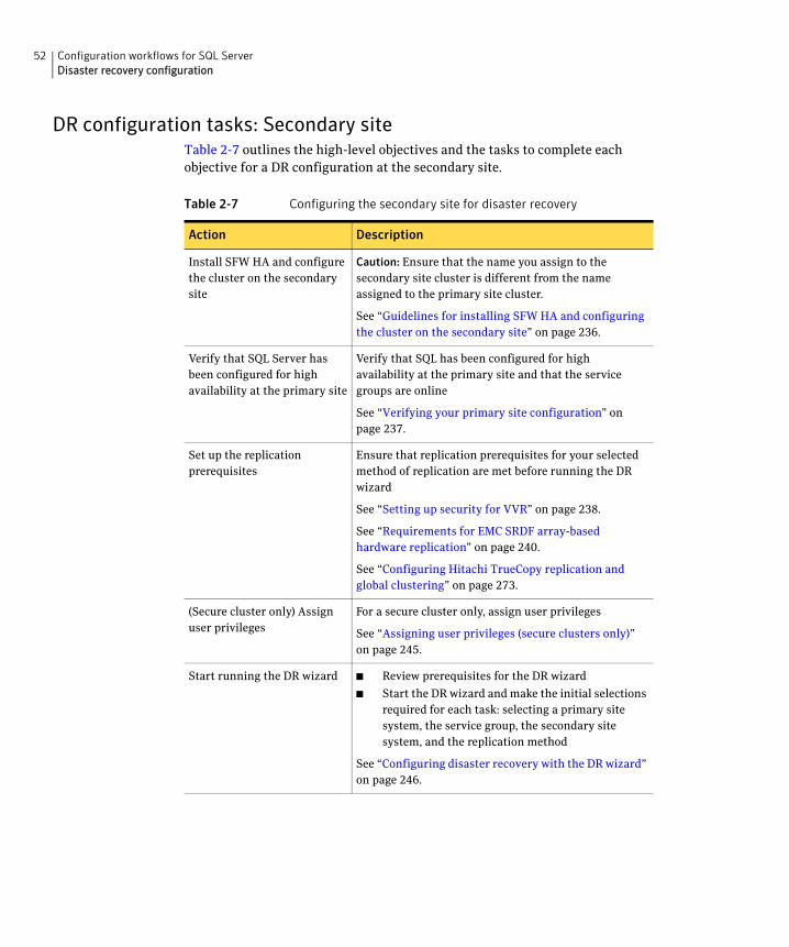
52 Configuration workflows for SQL ServerDisaster recovery configuration
DR configuration tasks: Secondary siteTable 2-7 outlines the high-level objectives and the tasks to complete each objective for a DR configuration at the secondary site.
Table 2-7 Configuring the secondary site for disaster recovery
Action Description
Install SFW HA and configure the cluster on the secondary site
Caution: Ensure that the name you assign to the secondary site cluster is different from the name assigned to the primary site cluster.
See “Guidelines for installing SFW HA and configuring the cluster on the secondary site” on page 236.
Verify that SQL Server has been configured for high availability at the primary site
Verify that SQL has been configured for high availability at the primary site and that the service groups are online
See “Verifying your primary site configuration” on page 237.
Set up the replication prerequisites
Ensure that replication prerequisites for your selected method of replication are met before running the DR wizard
See “Setting up security for VVR” on page 238.
See “Requirements for EMC SRDF array-based hardware replication” on page 240.
See “Configuring Hitachi TrueCopy replication and global clustering” on page 273.
(Secure cluster only) Assign user privileges
For a secure cluster only, assign user privileges
See “Assigning user privileges (secure clusters only)” on page 245.
Start running the DR wizard ■ Review prerequisites for the DR wizard
■ Start the DR wizard and make the initial selections required for each task: selecting a primary site system, the service group, the secondary site system, and the replication method
See “Configuring disaster recovery with the DR wizard” on page 246.
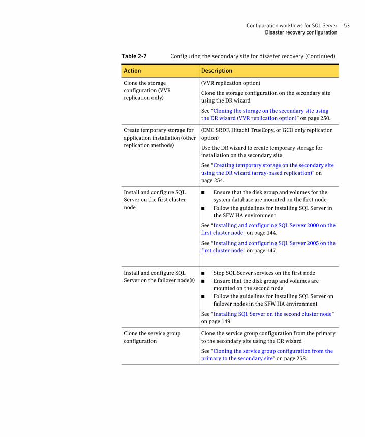
53Configuration workflows for SQL ServerDisaster recovery configuration
Clone the storage configuration (VVR replication only)
(VVR replication option)
Clone the storage configuration on the secondary site using the DR wizard
See “Cloning the storage on the secondary site using the DR wizard (VVR replication option)” on page 250.
Create temporary storage for application installation (other replication methods)
(EMC SRDF, Hitachi TrueCopy, or GCO only replication option)
Use the DR wizard to create temporary storage for installation on the secondary site
See “Creating temporary storage on the secondary site using the DR wizard (array-based replication)” on page 254.
Install and configure SQL Server on the first cluster node
■ Ensure that the disk group and volumes for the system database are mounted on the first node
■ Follow the guidelines for installing SQL Server in the SFW HA environment
See “Installing and configuring SQL Server 2000 on the first cluster node” on page 144.
See “Installing and configuring SQL Server 2005 on the first cluster node” on page 147.
Install and configure SQL Server on the failover node(s)
■ Stop SQL Server services on the first node
■ Ensure that the disk group and volumes are mounted on the second node
■ Follow the guidelines for installing SQL Server on failover nodes in the SFW HA environment
See “Installing SQL Server on the second cluster node” on page 149.
Clone the service group configuration
Clone the service group configuration from the primary to the secondary site using the DR wizard
See “Cloning the service group configuration from the primary to the secondary site” on page 258.
Table 2-7 Configuring the secondary site for disaster recovery (Continued)
Action Description
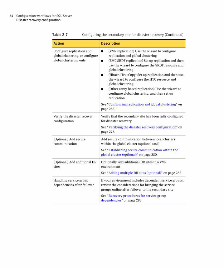
54 Configuration workflows for SQL ServerDisaster recovery configuration
Configure replication and global clustering, or configure global clustering only
■ (VVR replication) Use the wizard to configure replication and global clustering
■ (EMC SRDF replication) Set up replication and then use the wizard to configure the SRDF resource and global clustering
■ (Hitachi TrueCopy) Set up replication and then use the wizard to configure the HTC resource and global clustering
■ (Other array-based replication) Use the wizard to configure global clustering, and then set up replication
See “Configuring replication and global clustering” on page 262,
Verify the disaster recover configuration
Verify that the secondary site has been fully configured for disaster recovery
See “Verifying the disaster recovery configuration” on page 278.
(Optional) Add secure communication
Add secure communication between local clusters within the global cluster (optional task)
See “Establishing secure communication within the global cluster (optional)” on page 280.
(Optional) Add additional DR sites
Optionally, add additional DR sites to a VVR environment
See “Adding multiple DR sites (optional)” on page 282.
Handling service group dependencies after failover
If your environment includes dependent service groups, review the considerations for bringing the service groups online after failover to the secondary site
See “Recovery procedures for service group dependencies” on page 283.
Table 2-7 Configuring the secondary site for disaster recovery (Continued)
Action Description
Chapter
3Using the Solutions Configuration Center
This chapter covers the following topics:
■ About the Solutions Configuration Center
■ Starting the Configuration Center
■ Available options from the Configuration Center
■ About running the Configuration Center wizards
■ Following the workflow in the Configuration Center
■ Solutions wizard logs
About the Solutions Configuration CenterThe Storage Foundation and High Availability Solutions Configuration Center guides you through setting up your Veritas Storage Foundation for Windows (SFW) or SFW High Availability (HA) environment. The Configuration Center provides solutions for the following applications:
■ Microsoft Exchange Server 2003, 2007, and 2010
■ Microsoft SQL Server 2000, 2005, 2008, and 2008 R2
■ Enterprise Vault Server (high availability and disaster recovery solutions)
■ Microsoft SharePoint Server 2010 (high availability and disaster recovery solutions)
■ Additional applications
Depending on the application, the following solutions may be available:
■ High availability at a single site for a new installation
56 Using the Solutions Configuration CenterStarting the Configuration Center
■ High availability at a single site for an existing server
■ Campus cluster disaster recovery, including the following:
■ Campus cluster using Veritas Cluster Server (SFW HA)
■ Campus cluster using Microsoft clustering
■ Wide area disaster recovery involving multiple sites
■ Quick Recovery for on-host recovery from logical errors in application data (available for Microsoft Exchange 2003, 2007, 2010, and for Microsoft SQL Server 2005, 2008, and 2008 R2)
■ Fire drill to test the fault readiness of a disaster recovery environment
The Solutions Configuration Center provides two ways to access Solutions wizards:
■ The Applications tab lists solutions by application. It provides step-by-step configuration instructions that include buttons to launch the appropriate wizard for each step.
■ The Solutions tab, for advanced users, lists wizards by solution without additional instructions.
Starting the Configuration CenterYou can start the Configuration Center in the following ways:
■ Click Start > All Programs > Symantec > Veritas Storage Foundation > Solutions Configuration Center.
■ Click Start > All Programs > Symantec > Veritas Cluster Server > Solutions Configuration Center.
■ Click Start > Run and type scc.
57Using the Solutions Configuration CenterAvailable options from the Configuration Center
Available options from the Configuration CenterOn the Applications tab, the Solutions Configuration Center is context-sensitive to the application. For example, the solutions displayed when you click the application name are those available for that application. The Solution Guides listed in the right pane match the selected application.
In addition, some choices can vary depending on the operating system of the node on which you launch the wizard. For example, since Microsoft Exchange 2003 runs only on 32-bit operating systems, on a 64-bit system only the Exchange 2007 and Exchange 2010 configuration wizards are shown.
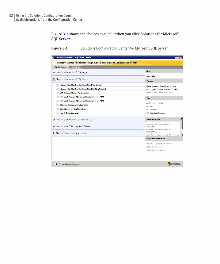
58 Using the Solutions Configuration CenterAvailable options from the Configuration Center
Figure 3-1 shows the choices available when you click Solutions for Microsoft SQL Server.
Figure 3-1 Solutions Configuration Center for Microsoft SQL Server
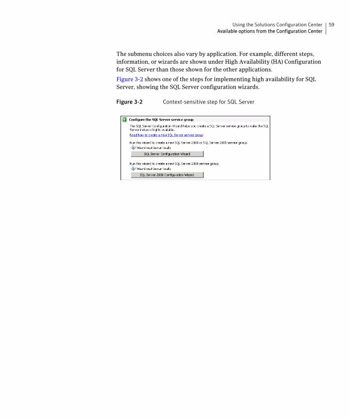
59Using the Solutions Configuration CenterAvailable options from the Configuration Center
The submenu choices also vary by application. For example, different steps, information, or wizards are shown under High Availability (HA) Configuration for SQL Server than those shown for the other applications.
Figure 3-2 shows one of the steps for implementing high availability for SQL Server, showing the SQL Server configuration wizards.
Figure 3-2 Context-sensitive step for SQL Server
60 Using the Solutions Configuration CenterAbout running the Configuration Center wizards
About running the Configuration Center wizardsYou can run the wizards from the Applications tab if you are walking through the configuration steps on the Solutions Configuration Center. If you are already familiar with configuration, you can also go directly to a particular wizard by selecting the Solutions tab.
The Configuration Center and some wizards can be run from a remote system. Wizards that you can run remotely include the following:
Wizards related to storage configuration and application installation must be run locally on the system where the process is occurring. Wizards that you must run locally include the following:
VCS Configuration Wizard Sets up the VCS cluster
Disaster Recovery Configuration Wizard
Configures wide area disaster recovery, including cloning storage, cloning service groups, and configuring the global cluster
Also can configure Veritas Volume Replicator (VVR) replication or configure the VCS resource for EMC SRDF and Hitachi TrueCopy array-based hardware replication
Requires first configuring high availability on the primary site
Quick Recovery Configuration Wizard
Schedules preparation of snapshot mirrors and schedules the Quick Recovery snapshots
Fire Drill Wizard Sets up a fire drill to test disaster recovery
Requires configuring disaster recovery first
New Dynamic Disk Group Wizard
Launched from the Veritas Enterprise Administrator console
New Volume Wizard Launched from the Veritas Enterprise Administrator console
Exchange Setup Wizard Installs and configures Microsoft Exchange Server 2003 and 2007 for the high availability environment
If Microsoft Exchange is already installed, refer to the documentation for further instructions.
This wizard is not required for Exchange Server 2010.
Exchange Configuration Wizard
Configures the service group for Microsoft Exchange Server 2003 and 2007 high availability
Exchange 2010 Configuration Wizard
Configures the service group for Microsoft Exchange Server 2010 high availability
61Using the Solutions Configuration CenterAbout running the Configuration Center wizards
The Additional Applications section of the Configuration Center provides wizards to be run locally for creating service groups for the following applications or server roles:
SQL Server Configuration Wizard
Configures the service group for SQL Server 2000 or SQL Server 2005 high availability
You must first install SQL Server on each node according to the instructions in the documentation.
SQL Server 2008 Configuration Wizard
Configures the service group for SQL Server 2008 or SQL Server 2008 R2 high availability
You must first install SQL server on each node according to the instructions in the documentation.
Enterprise Vault Cluster Setup Wizard
Configures the service group for Enterprise Vault Server high availability
MSDTC Wizard Configures an MSDTC server service group for SQL Server 2000, 2005, or 2008 environments
MSMQ Configuration Wizard
Configures a Microsoft Message Queuing (MSMQ) service group
SharePoint 2010 Configuration Wizard
Configures SharePoint Server 2010 service groups
You can run the wizard from any SFW HA cluster node where SharePoint Server is installed and configured.
File Share Configuration Wizard
Configures file shares for high availability
Print Share Configuration Wizard
Configures print shares for high availability
IIS Configuration Wizard Configures IIS for high availability
MSVirtual Machine Configuration Wizard
Configures MS Virtual Machine for high availability
Oracle Agent Configuration Wizard
Configures Oracle for high availability
Application Configuration Wizard
Configures any other application service group for which application-specific wizards have not been provided
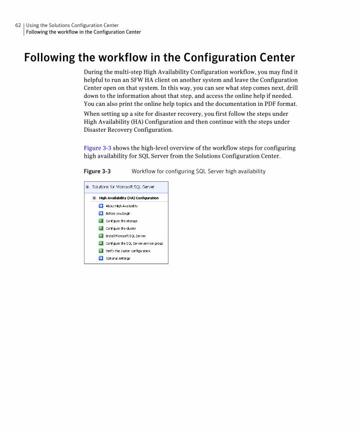
62 Using the Solutions Configuration CenterFollowing the workflow in the Configuration Center
Following the workflow in the Configuration CenterDuring the multi-step High Availability Configuration workflow, you may find it helpful to run an SFW HA client on another system and leave the Configuration Center open on that system. In this way, you can see what step comes next, drill down to the information about that step, and access the online help if needed. You can also print the online help topics and the documentation in PDF format.
When setting up a site for disaster recovery, you first follow the steps under High Availability (HA) Configuration and then continue with the steps under Disaster Recovery Configuration.
Figure 3-3 shows the high-level overview of the workflow steps for configuring high availability for SQL Server from the Solutions Configuration Center.
Figure 3-3 Workflow for configuring SQL Server high availability
63Using the Solutions Configuration CenterSolutions wizard logs
Solutions wizard logsThe Solutions Configuration Center provides access to many wizards. However, three wizards are built in to the Solutions Configuration Center:
■ Disaster Recovery Wizard
■ Fire Drill Wizard
■ Quick Recovery Configuration Wizard
These three Solutions wizards are launched only from the Solutions Configuration Center, whereas other wizards can be launched from product consoles or the Start menu.
Logs created by these three Solutions wizards are located in the following paths:
For Windows Server 2003:
C:\Documents and Settings\All Users\Application
Data\VERITAS\winsolutions\log
For Windows Server 2008:
C:\ProgramData\Veritas\winsolutions\log

64 Using the Solutions Configuration CenterSolutions wizard logs
Section
3 Requirements and PlanningThis section contains the following chapter:
■ Requirements and planning for your HA and DR configurations

66
Chapter
4Requirements and planning for your HA and DR configurations
This chapter contains the following topics:
■ Reviewing the requirements
■ Reviewing the prerequisites for a standalone SQL Server
■ Reviewing the HA configuration
■ Following the HA workflow in the Solutions Configuration Center
■ Reviewing a standalone SQL Server configuration
■ Reviewing the MSDTC configuration
■ Reviewing the campus cluster configuration
■ Reviewing the Replicated Data Cluster configuration
■ About setting up a Replicated Data Cluster configuration
■ Reviewing the disaster recovery configuration
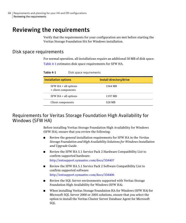
68 Requirements and planning for your HA and DR configurationsReviewing the requirements
Reviewing the requirementsVerify that the requirements for your configuration are met before starting the Veritas Storage Foundation HA for Windows installation.
Disk space requirementsFor normal operation, all installations require an additional 50 MB of disk space.
Table 4-1 estimates disk space requirements for SFW HA.
Requirements for Veritas Storage Foundation High Availability for Windows (SFW HA)
Before installing Veritas Storage Foundation High Availability for Windows (SFW HA), ensure that you review the following:
■ Review the general installation requirements for SFW HA in the Veritas Storage Foundation and High Availability Solutions for Windows Installation and Upgrade Guide.
■ Review the SFW HA 5.1 Service Pack 2 Hardware Compatibility List to confirm supported hardware:
http://entsupport.symantec.com/docs/358407
■ Review the SFW HA 5.1 Service Pack 2 Software Compatibility List to confirm supported software:
http://entsupport.symantec.com/docs/358406
■ Review the SQL Server environments supported with Veritas Storage Foundation High Availability for Windows (SFW HA).
■ When installing Veritas Storage Foundation HA for Windows (SFW HA) for Microsoft SQL Server 2000 or 2005 solutions, ensure that you select the option to install the Veritas Cluster Server Database Agent for Microsoft SQL.
Table 4-1 Disk space requirements
Installation options Install directory/drive
SFW HA + all options + client components
1564 MB
SFW HA + all options 1197 MB
Client components 528 MB
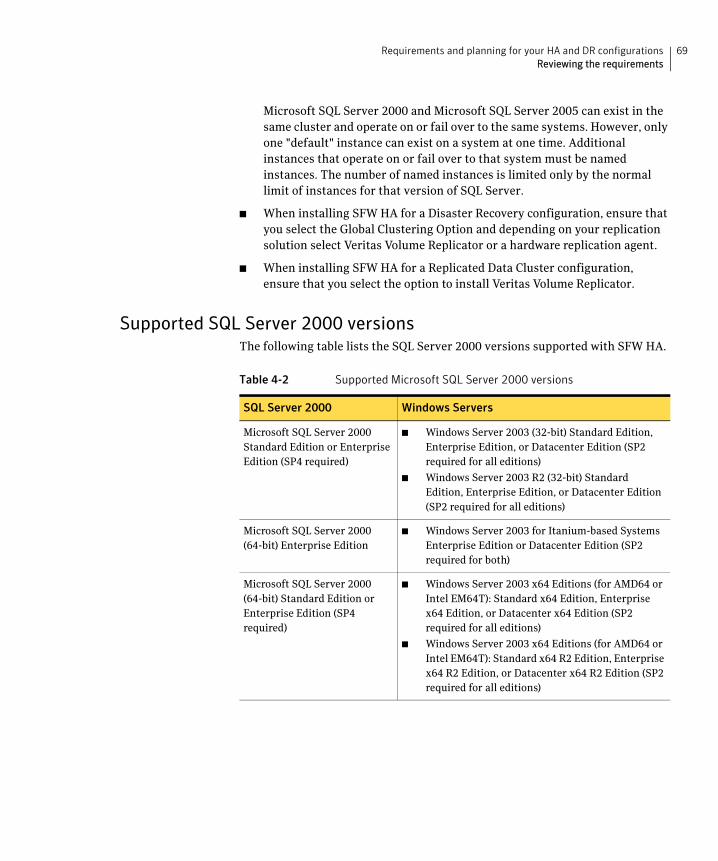
69Requirements and planning for your HA and DR configurationsReviewing the requirements
Microsoft SQL Server 2000 and Microsoft SQL Server 2005 can exist in the same cluster and operate on or fail over to the same systems. However, only one "default" instance can exist on a system at one time. Additional instances that operate on or fail over to that system must be named instances. The number of named instances is limited only by the normal limit of instances for that version of SQL Server.
■ When installing SFW HA for a Disaster Recovery configuration, ensure that you select the Global Clustering Option and depending on your replication solution select Veritas Volume Replicator or a hardware replication agent.
■ When installing SFW HA for a Replicated Data Cluster configuration, ensure that you select the option to install Veritas Volume Replicator.
Supported SQL Server 2000 versionsThe following table lists the SQL Server 2000 versions supported with SFW HA.
Table 4-2 Supported Microsoft SQL Server 2000 versions
SQL Server 2000 Windows Servers
Microsoft SQL Server 2000 Standard Edition or Enterprise Edition (SP4 required)
■ Windows Server 2003 (32-bit) Standard Edition, Enterprise Edition, or Datacenter Edition (SP2 required for all editions)
■ Windows Server 2003 R2 (32-bit) Standard Edition, Enterprise Edition, or Datacenter Edition (SP2 required for all editions)
Microsoft SQL Server 2000 (64-bit) Enterprise Edition
■ Windows Server 2003 for Itanium-based Systems Enterprise Edition or Datacenter Edition (SP2 required for both)
Microsoft SQL Server 2000 (64-bit) Standard Edition or Enterprise Edition (SP4 required)
■ Windows Server 2003 x64 Editions (for AMD64 or Intel EM64T): Standard x64 Edition, Enterprise x64 Edition, or Datacenter x64 Edition (SP2 required for all editions)
■ Windows Server 2003 x64 Editions (for AMD64 or Intel EM64T): Standard x64 R2 Edition, Enterprise x64 R2 Edition, or Datacenter x64 R2 Edition (SP2 required for all editions)
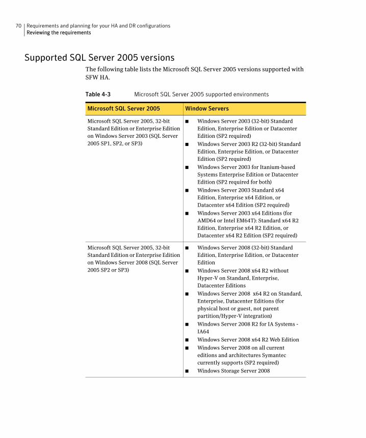
70 Requirements and planning for your HA and DR configurationsReviewing the requirements
Supported SQL Server 2005 versionsThe following table lists the Microsoft SQL Server 2005 versions supported with SFW HA.
Table 4-3 Microsoft SQL Server 2005 supported environments
Microsoft SQL Server 2005 Window Servers
Microsoft SQL Server 2005, 32-bit Standard Edition or Enterprise Edition on Windows Server 2003 (SQL Server 2005 SP1, SP2, or SP3)
■ Windows Server 2003 (32-bit) Standard Edition, Enterprise Edition or Datacenter Edition (SP2 required)
■ Windows Server 2003 R2 (32-bit) Standard Edition, Enterprise Edition, or Datacenter Edition (SP2 required)
■ Windows Server 2003 for Itanium-based Systems Enterprise Edition or Datacenter Edition (SP2 required for both)
■ Windows Server 2003 Standard x64 Edition, Enterprise x64 Edition, or Datacenter x64 Edition (SP2 required)
■ Windows Server 2003 x64 Editions (for AMD64 or Intel EM64T): Standard x64 R2 Edition, Enterprise x64 R2 Edition, or Datacenter x64 R2 Edition (SP2 required)
Microsoft SQL Server 2005, 32-bit Standard Edition or Enterprise Edition on Windows Server 2008 (SQL Server 2005 SP2 or SP3)
■ Windows Server 2008 (32-bit) Standard Edition, Enterprise Edition, or Datacenter Edition
■ Windows Server 2008 x64 R2 without Hyper-V on Standard, Enterprise, Datacenter Editions
■ Windows Server 2008 x64 R2 on Standard, Enterprise, Datacenter Editions (for physical host or guest, not parent partition/Hyper-V integration)
■ Windows Server 2008 R2 for IA Systems - IA64
■ Windows Server 2008 x64 R2 Web Edition
■ Windows Server 2008 on all current editions and architectures Symantec currently supports (SP2 required)
■ Windows Storage Server 2008
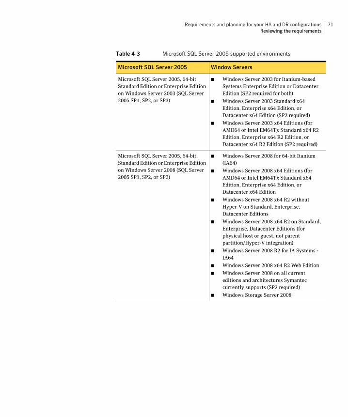
71Requirements and planning for your HA and DR configurationsReviewing the requirements
Microsoft SQL Server 2005, 64-bit Standard Edition or Enterprise Edition on Windows Server 2003 (SQL Server 2005 SP1, SP2, or SP3)
■ Windows Server 2003 for Itanium-based Systems Enterprise Edition or Datacenter Edition (SP2 required for both)
■ Windows Server 2003 Standard x64 Edition, Enterprise x64 Edition, or Datacenter x64 Edition (SP2 required)
■ Windows Server 2003 x64 Editions (for AMD64 or Intel EM64T): Standard x64 R2 Edition, Enterprise x64 R2 Edition, or Datacenter x64 R2 Edition (SP2 required)
Microsoft SQL Server 2005, 64-bit Standard Edition or Enterprise Edition on Windows Server 2008 (SQL Server 2005 SP1, SP2, or SP3)
■ Windows Server 2008 for 64-bit Itanium (IA64)
■ Windows Server 2008 x64 Editions (for AMD64 or Intel EM64T): Standard x64 Edition, Enterprise x64 Edition, or Datacenter x64 Edition
■ Windows Server 2008 x64 R2 without Hyper-V on Standard, Enterprise, Datacenter Editions
■ Windows Server 2008 x64 R2 on Standard, Enterprise, Datacenter Editions (for physical host or guest, not parent partition/Hyper-V integration)
■ Windows Server 2008 R2 for IA Systems - IA64
■ Windows Server 2008 x64 R2 Web Edition
■ Windows Server 2008 on all current editions and architectures Symantec currently supports (SP2 required)
■ Windows Storage Server 2008
Table 4-3 Microsoft SQL Server 2005 supported environments
Microsoft SQL Server 2005 Window Servers
72 Requirements and planning for your HA and DR configurationsReviewing the requirements
System requirements for SFW HASystems must meet the following requirements for SFW HA:
■ Memory must be a minimum 1 GB of RAM per server for SFW HA.
■ Memory must be a minimum 1 GB of RAM per server for SQL Server; refer to the Microsoft documentation for more information.
■ Shared disks to support applications that migrate between nodes in the cluster. Campus clusters require more than one array for mirroring. Disaster recovery configurations require one array for each site. Replicated data clusters with no shared storage are also supported.
If your storage devices are SCSI-3 compliant, and you wish to use SCSI-3 Persistent Group Reservations (PGR), you must enable SCSI-3 support using the Veritas Enterprise Administrator (VEA). See the Veritas Storage Foundation Administrator’s Guide for more information.
■ SCSI, Fibre Channel, iSCSI host bus adapters (HBAs), or iSCSI Initiator supported NICs to access shared storage.
■ A minimum of two NICs is required. One NIC will be used exclusively for private network communication between the nodes of the cluster. The second NIC will be used for both private cluster communications and for public access to the cluster. Symantec recommends three NICs.
See “Best practices for SFW HA” on page 74.
■ NIC teaming is not supported for the VCS private network.
■ All servers must have the same system architecture, run the same operating system, and be at the same service pack (SP) level.
Network requirements for SFW HASFW HA has the following network requirements:
■ Install SFW HA on servers in a Windows Server 2003 or Windows Server 2008 domain.
■ Do not install SFW HA on servers that are assigned the role of a Domain Controller. Configuring a cluster on a domain controller is not supported.
■ Ensure that your firewall settings allow access to ports used by SFW HA wizards and services. For a detailed list of services and ports used by SFW HA, refer to the Veritas Storage Foundation and High Availability Solutions for Windows Installation and Upgrade Guide.
■ Static IP addresses for the following purposes:
■ One static IP address available per site for each SQL Virtual Server.
73Requirements and planning for your HA and DR configurationsReviewing the requirements
■ A minimum of one static IP address for each physical node in the cluster.
■ One static IP address per cluster used when configuring Notification or the Global Cluster Option. The same IP address may be used for all options.
■ For VVR replication in a disaster recovery configuration, a minimum of one static IP address per site for each application instance running in the cluster.
■ For VVR replication in a Replicated Data Cluster configuration, a minimum of one static IP address per zone for each application instance running in the cluster.
■ Configure name resolution for each node.
■ Verify the availability of DNS Services. AD-integrated DNS or BIND 8.2 or higher are supported.
Make sure a reverse lookup zone exists in the DNS. Refer to the application documentation for instructions on creating a reverse lookup zone.
■ DNS scavenging affects virtual servers configured in VCS because the Lanman agent uses Dynamic DNS (DDNS) to map virtual names with IP addresses. If you use scavenging, then you must set the DNSRefreshInterval attribute for the Lanman agent. This enables the Lanman agent to refresh the resource records on the DNS servers.
See the Veritas Cluster Server Bundled Agents Reference Guide.
Permission requirements for SFW HAThe following permissions are required:
■ You must be a domain user.
■ You must be a member of the local Administrators group on all nodes where you are installing.
■ You must have write permissions for the Active Directory objects corresponding to all the nodes.
■ If you plan to create a new user account for the VCS Helper service, you must have Domain Administrator privileges or belong to the Account Operators group. If you plan to use an existing user account context for the VCS Helper service, you must know the password for the user account.
Additional requirements for SFW HAPlease review the following additional requirements:
74 Requirements and planning for your HA and DR configurationsReviewing the prerequisites for a standalone SQL Server
■ Installation media for all products and third-party applications.
■ Licenses for all products and third-party applications.
■ You must install the operating system in the same path on all systems. For example, if you install Windows Server on C:\WINDOWS of one node, installations on all other nodes must be on C:\WINDOWS. Make sure that the same drive letter is available on all nodes and that the system drive has adequate space for the installation.
■ Before you begin installing SQL Server 2005, verify that Microsoft Internet Information Services (IIS) is installed and enabled on the system.
■ For a Replicated Data Cluster, install only in a single domain.
Best practices for SFW HASymantec recommends that you perform the following tasks:
■ Configure Microsoft Exchange Server and Microsoft SQL Server on separate failover nodes within a cluster.
■ Verify that you have three network adapters (two NICs exclusively for the private network and one for the public network).
When using only two NICs, lower the priority of one NIC and use the low-priority NIC for public and private communication.
■ Route each private NIC through a separate hub or switch to avoid single points of failure.
■ NIC teaming is not supported for the VCS private network.
■ Verify that your DNS server is configured for secure dynamic updates. For the Forward and Reverse Lookup Zones, set the Dynamic updates option to "Secure only". (DNS > Zone Properties > General tab)
■ Although you can use a single node cluster as the primary and secondary zones, you must create the disk groups as clustered disk groups. If you cannot create a clustered disk group due to the unavailability of disks on a shared bus, use the vxclus UseSystemBus ON command. This is applicable for a Replicated Data Cluster configuration.
Reviewing the prerequisites for a standalone SQL Server
This is applicable if you are configuring an existing standalone SQL Server for high availability.
75Requirements and planning for your HA and DR configurationsReviewing the prerequisites for a standalone SQL Server
Review the following requirements before you begin the process of installing Veritas Storage Foundation HA for Windows and creating a clustered environment:
■ Create a backup of the data on the existing standalone SQL Server.
■ For SQL Server 2005, set all SQL Server 2005 services to manual start, except for the SQL Browser service. Ensure that the SQL Browser service is set to automatic.
Refer to the SQL Server documentation for instructions.
■ For SQL Server 2000, set all SQL Server 2000 services to manual start.
Refer to the SQL Server documentation for instructions.
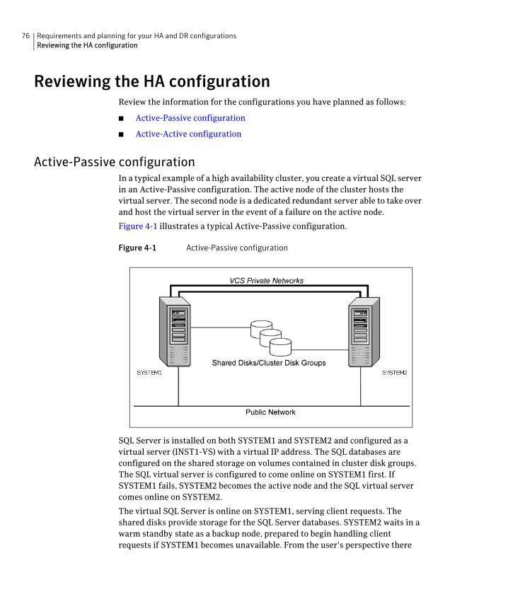
76 Requirements and planning for your HA and DR configurationsReviewing the HA configuration
Reviewing the HA configurationReview the information for the configurations you have planned as follows:
■ Active-Passive configuration
■ Active-Active configuration
Active-Passive configurationIn a typical example of a high availability cluster, you create a virtual SQL server in an Active-Passive configuration. The active node of the cluster hosts the virtual server. The second node is a dedicated redundant server able to take over and host the virtual server in the event of a failure on the active node.
Figure 4-1 illustrates a typical Active-Passive configuration.
Figure 4-1 Active-Passive configuration
SQL Server is installed on both SYSTEM1 and SYSTEM2 and configured as a virtual server (INST1-VS) with a virtual IP address. The SQL databases are configured on the shared storage on volumes contained in cluster disk groups. The SQL virtual server is configured to come online on SYSTEM1 first. If SYSTEM1 fails, SYSTEM2 becomes the active node and the SQL virtual server comes online on SYSTEM2.
The virtual SQL Server is online on SYSTEM1, serving client requests. The shared disks provide storage for the SQL Server databases. SYSTEM2 waits in a warm standby state as a backup node, prepared to begin handling client requests if SYSTEM1 becomes unavailable. From the user’s perspective there
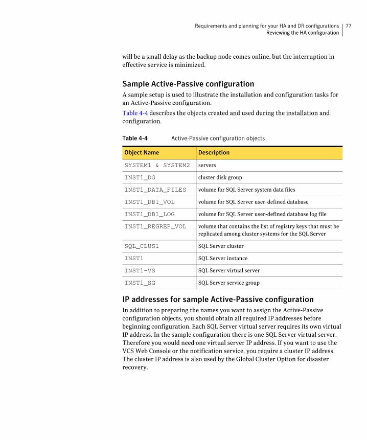
77Requirements and planning for your HA and DR configurationsReviewing the HA configuration
will be a small delay as the backup node comes online, but the interruption in effective service is minimized.
Sample Active-Passive configurationA sample setup is used to illustrate the installation and configuration tasks for an Active-Passive configuration.
Table 4-4 describes the objects created and used during the installation and configuration.
IP addresses for sample Active-Passive configurationIn addition to preparing the names you want to assign the Active-Passive configuration objects, you should obtain all required IP addresses before beginning configuration. Each SQL Server virtual server requires its own virtual IP address. In the sample configuration there is one SQL Server virtual server. Therefore you would need one virtual server IP address. If you want to use the VCS Web Console or the notification service, you require a cluster IP address. The cluster IP address is also used by the Global Cluster Option for disaster recovery.
Table 4-4 Active-Passive configuration objects
Object Name Description
SYSTEM1 & SYSTEM2 servers
INST1_DG cluster disk group
INST1_DATA_FILES volume for SQL Server system data files
INST1_DB1_VOL volume for SQL Server user-defined database
INST1_DB1_LOG volume for SQL Server user-defined database log file
INST1_REGREP_VOL volume that contains the list of registry keys that must be replicated among cluster systems for the SQL Server
SQL_CLUS1 SQL Server cluster
INST1 SQL Server instance
INST1-VS SQL Server virtual server
INST1_SG SQL Server service group
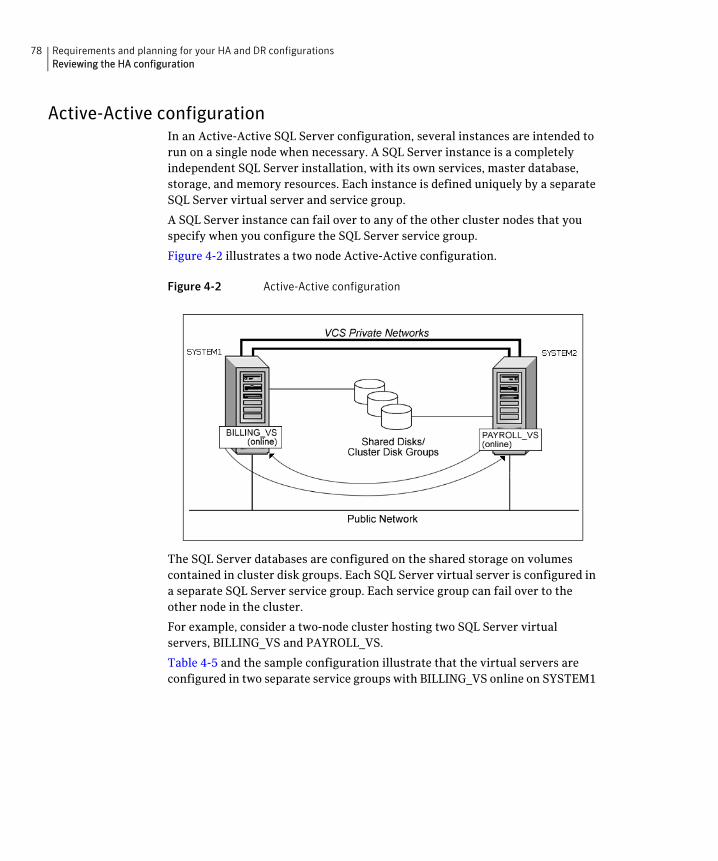
78 Requirements and planning for your HA and DR configurationsReviewing the HA configuration
Active-Active configurationIn an Active-Active SQL Server configuration, several instances are intended to run on a single node when necessary. A SQL Server instance is a completely independent SQL Server installation, with its own services, master database, storage, and memory resources. Each instance is defined uniquely by a separate SQL Server virtual server and service group.
A SQL Server instance can fail over to any of the other cluster nodes that you specify when you configure the SQL Server service group.
Figure 4-2 illustrates a two node Active-Active configuration.
Figure 4-2 Active-Active configuration
The SQL Server databases are configured on the shared storage on volumes contained in cluster disk groups. Each SQL Server virtual server is configured in a separate SQL Server service group. Each service group can fail over to the other node in the cluster.
For example, consider a two-node cluster hosting two SQL Server virtual servers, BILLING_VS and PAYROLL_VS.
Table 4-5 and the sample configuration illustrate that the virtual servers are configured in two separate service groups with BILLING_VS online on SYSTEM1
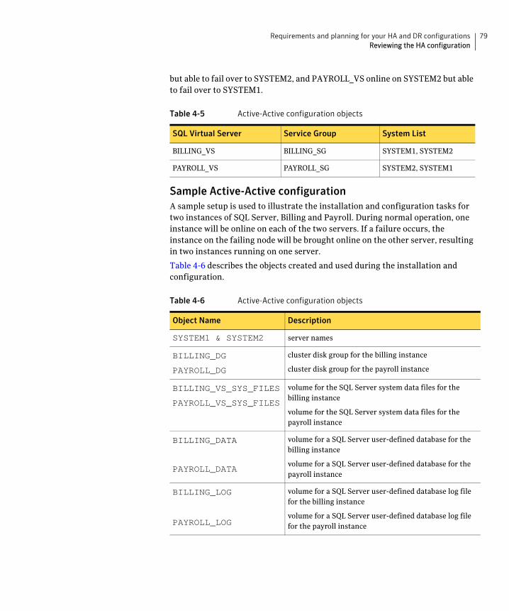
79Requirements and planning for your HA and DR configurationsReviewing the HA configuration
but able to fail over to SYSTEM2, and PAYROLL_VS online on SYSTEM2 but able to fail over to SYSTEM1.
Sample Active-Active configurationA sample setup is used to illustrate the installation and configuration tasks for two instances of SQL Server, Billing and Payroll. During normal operation, one instance will be online on each of the two servers. If a failure occurs, the instance on the failing node will be brought online on the other server, resulting in two instances running on one server.
Table 4-6 describes the objects created and used during the installation and configuration.
Table 4-5 Active-Active configuration objects
SQL Virtual Server Service Group System List
BILLING_VS BILLING_SG SYSTEM1, SYSTEM2
PAYROLL_VS PAYROLL_SG SYSTEM2, SYSTEM1
Table 4-6 Active-Active configuration objects
Object Name Description
SYSTEM1 & SYSTEM2 server names
BILLING_DG
PAYROLL_DG
cluster disk group for the billing instance
cluster disk group for the payroll instance
BILLING_VS_SYS_FILES
PAYROLL_VS_SYS_FILES
volume for the SQL Server system data files for the billing instance
volume for the SQL Server system data files for the payroll instance
BILLING_DATA
PAYROLL_DATA
volume for a SQL Server user-defined database for the billing instance
volume for a SQL Server user-defined database for the payroll instance
BILLING_LOG
PAYROLL_LOG
volume for a SQL Server user-defined database log file for the billing instance
volume for a SQL Server user-defined database log file for the payroll instance
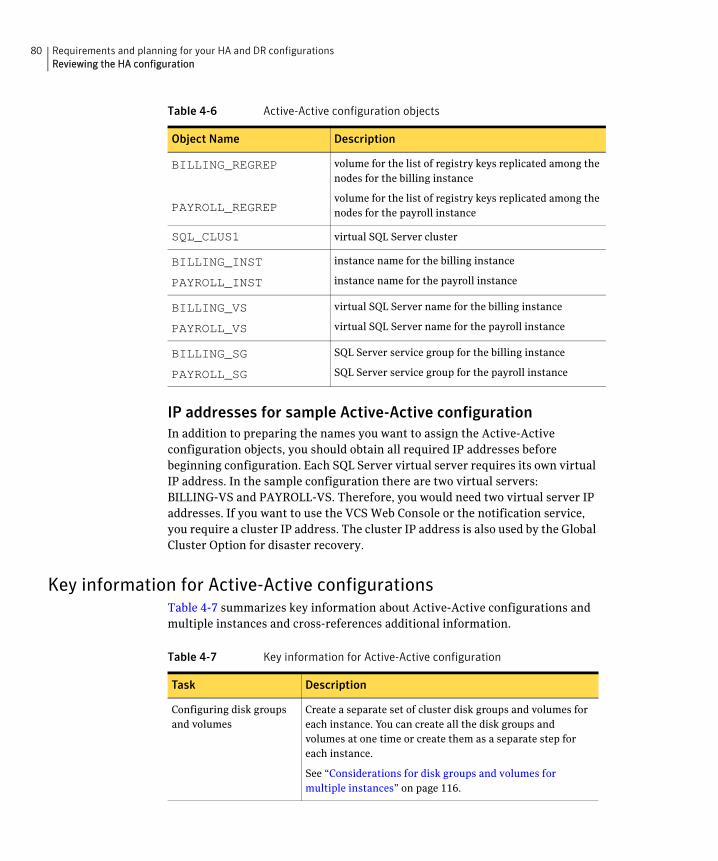
80 Requirements and planning for your HA and DR configurationsReviewing the HA configuration
IP addresses for sample Active-Active configurationIn addition to preparing the names you want to assign the Active-Active configuration objects, you should obtain all required IP addresses before beginning configuration. Each SQL Server virtual server requires its own virtual IP address. In the sample configuration there are two virtual servers: BILLING-VS and PAYROLL-VS. Therefore, you would need two virtual server IP addresses. If you want to use the VCS Web Console or the notification service, you require a cluster IP address. The cluster IP address is also used by the Global Cluster Option for disaster recovery.
Key information for Active-Active configurationsTable 4-7 summarizes key information about Active-Active configurations and multiple instances and cross-references additional information.
BILLING_REGREP
PAYROLL_REGREP
volume for the list of registry keys replicated among the nodes for the billing instance
volume for the list of registry keys replicated among the nodes for the payroll instance
SQL_CLUS1 virtual SQL Server cluster
BILLING_INST
PAYROLL_INST
instance name for the billing instance
instance name for the payroll instance
BILLING_VS
PAYROLL_VS
virtual SQL Server name for the billing instance
virtual SQL Server name for the payroll instance
BILLING_SG
PAYROLL_SG
SQL Server service group for the billing instance
SQL Server service group for the payroll instance
Table 4-6 Active-Active configuration objects
Object Name Description
Table 4-7 Key information for Active-Active configuration
Task Description
Configuring disk groups and volumes
Create a separate set of cluster disk groups and volumes for each instance. You can create all the disk groups and volumes at one time or create them as a separate step for each instance.
See “Considerations for disk groups and volumes for multiple instances” on page 116.
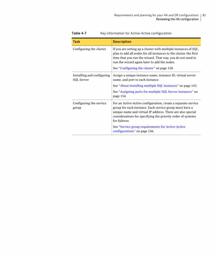
81Requirements and planning for your HA and DR configurationsReviewing the HA configuration
Configuring the cluster If you are setting up a cluster with multiple instances of SQL, plan to add all nodes for all instances to the cluster the first time that you run the wizard. That way, you do not need to run the wizard again later to add the nodes.
See “Configuring the cluster” on page 128.
Installing and configuring SQL Server
Assign a unique instance name, instance ID, virtual server name, and port to each instance.
See “About installing multiple SQL instances” on page 143.
See “Assigning ports for multiple SQL Server instances” on page 154.
Configuring the service group
For an Active-Active configuration, create a separate service group for each instance. Each service group must have a unique name and virtual IP address. There are also special considerations for specifying the priority order of systems for failover.
See “Service group requirements for Active-Active configurations” on page 156.
Table 4-7 Key information for Active-Active configuration
Task Description
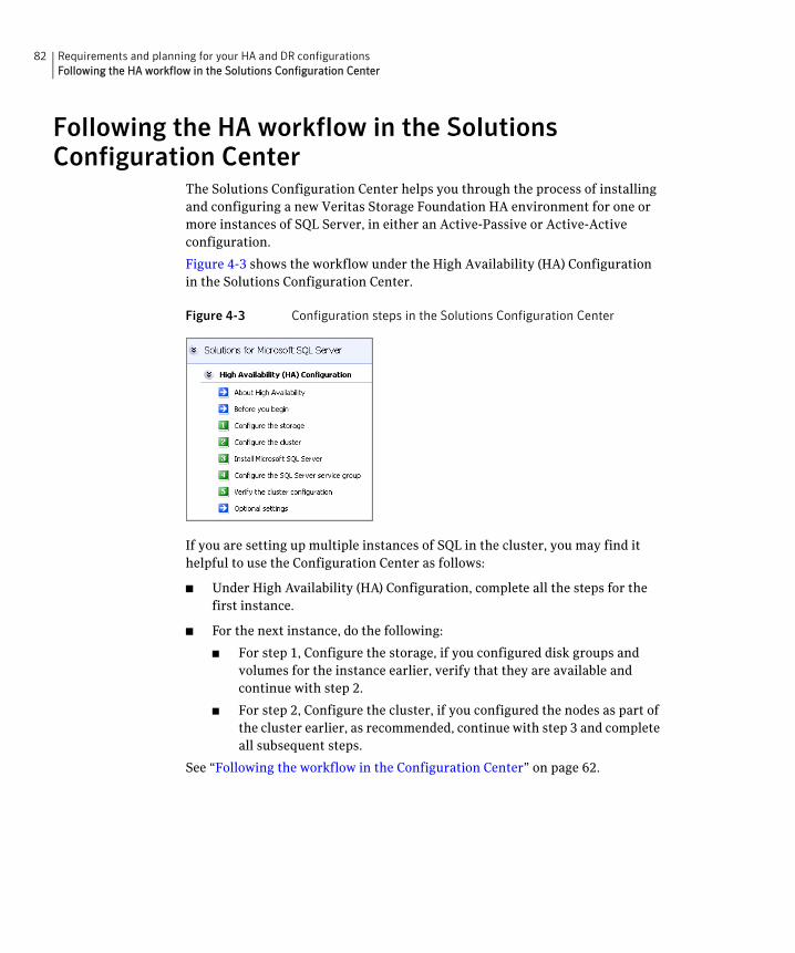
82 Requirements and planning for your HA and DR configurationsFollowing the HA workflow in the Solutions Configuration Center
Following the HA workflow in the Solutions Configuration Center
The Solutions Configuration Center helps you through the process of installing and configuring a new Veritas Storage Foundation HA environment for one or more instances of SQL Server, in either an Active-Passive or Active-Active configuration.
Figure 4-3 shows the workflow under the High Availability (HA) Configuration in the Solutions Configuration Center.
Figure 4-3 Configuration steps in the Solutions Configuration Center
If you are setting up multiple instances of SQL in the cluster, you may find it helpful to use the Configuration Center as follows:
■ Under High Availability (HA) Configuration, complete all the steps for the first instance.
■ For the next instance, do the following:
■ For step 1, Configure the storage, if you configured disk groups and volumes for the instance earlier, verify that they are available and continue with step 2.
■ For step 2, Configure the cluster, if you configured the nodes as part of the cluster earlier, as recommended, continue with step 3 and complete all subsequent steps.
See “Following the workflow in the Configuration Center” on page 62.
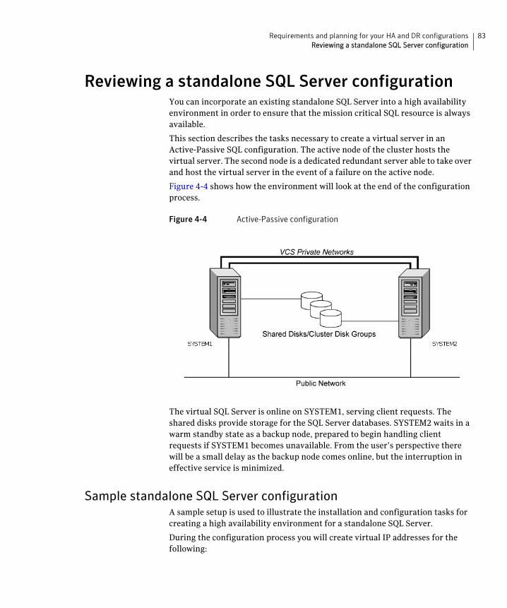
83Requirements and planning for your HA and DR configurationsReviewing a standalone SQL Server configuration
Reviewing a standalone SQL Server configurationYou can incorporate an existing standalone SQL Server into a high availability environment in order to ensure that the mission critical SQL resource is always available.
This section describes the tasks necessary to create a virtual server in an Active-Passive SQL configuration. The active node of the cluster hosts the virtual server. The second node is a dedicated redundant server able to take over and host the virtual server in the event of a failure on the active node.
Figure 4-4 shows how the environment will look at the end of the configuration process.
Figure 4-4 Active-Passive configuration
The virtual SQL Server is online on SYSTEM1, serving client requests. The shared disks provide storage for the SQL Server databases. SYSTEM2 waits in a warm standby state as a backup node, prepared to begin handling client requests if SYSTEM1 becomes unavailable. From the user’s perspective there will be a small delay as the backup node comes online, but the interruption in effective service is minimized.
Sample standalone SQL Server configurationA sample setup is used to illustrate the installation and configuration tasks for creating a high availability environment for a standalone SQL Server.
During the configuration process you will create virtual IP addresses for the following:
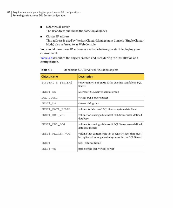
84 Requirements and planning for your HA and DR configurationsReviewing a standalone SQL Server configuration
■ SQL virtual server
The IP address should be the same on all nodes.
■ Cluster IP address
This address is used by Veritas Cluster Management Console (Single Cluster Mode) also referred to as Web Console.
You should have these IP addresses available before you start deploying your environment.
Table 4-8 describes the objects created and used during the installation and configuration.
Table 4-8 Standalone SQL Server configuration objects
Object Name Description
SYSTEM1 & SYSTEM2 server names; SYSTEM1 is the existing standalone SQL Server
INST1_SG Microsoft SQL Server service group
SQL_CLUS1 virtual SQL Server cluster
INST1_DG cluster disk group
INST1_DATA_FILES volume for Microsoft SQL Server system data files
INST1_DB1_VOL volume for storing a Microsoft SQL Server user-defined database
INST1_DB1_LOG volume for storing a Microsoft SQL Server user-defined database log file
INST1_REGREP_VOL volume that contains the list of registry keys that must be replicated among cluster systems for the SQL Server
INST1 SQL Instance Name
INST1-VS name of the SQL Virtual Server
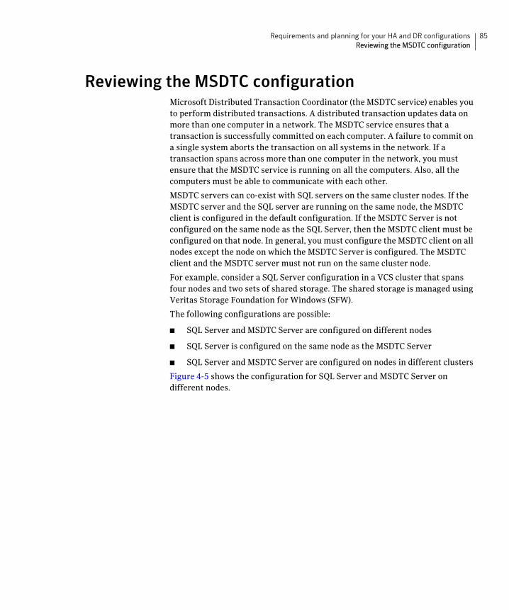
85Requirements and planning for your HA and DR configurationsReviewing the MSDTC configuration
Reviewing the MSDTC configurationMicrosoft Distributed Transaction Coordinator (the MSDTC service) enables you to perform distributed transactions. A distributed transaction updates data on more than one computer in a network. The MSDTC service ensures that a transaction is successfully committed on each computer. A failure to commit on a single system aborts the transaction on all systems in the network. If a transaction spans across more than one computer in the network, you must ensure that the MSDTC service is running on all the computers. Also, all the computers must be able to communicate with each other.
MSDTC servers can co-exist with SQL servers on the same cluster nodes. If the MSDTC server and the SQL server are running on the same node, the MSDTC client is configured in the default configuration. If the MSDTC Server is not configured on the same node as the SQL Server, then the MSDTC client must be configured on that node. In general, you must configure the MSDTC client on all nodes except the node on which the MSDTC Server is configured. The MSDTC client and the MSDTC server must not run on the same cluster node.
For example, consider a SQL Server configuration in a VCS cluster that spans four nodes and two sets of shared storage. The shared storage is managed using Veritas Storage Foundation for Windows (SFW).
The following configurations are possible:
■ SQL Server and MSDTC Server are configured on different nodes
■ SQL Server is configured on the same node as the MSDTC Server
■ SQL Server and MSDTC Server are configured on nodes in different clusters
Figure 4-5 shows the configuration for SQL Server and MSDTC Server on different nodes.
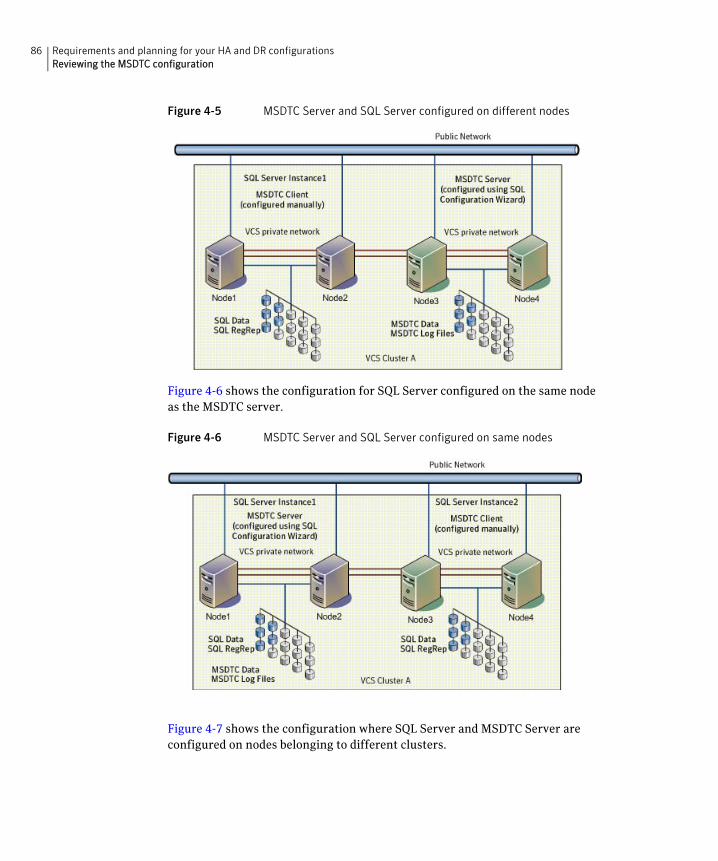
86 Requirements and planning for your HA and DR configurationsReviewing the MSDTC configuration
Figure 4-5 MSDTC Server and SQL Server configured on different nodes
Figure 4-6 shows the configuration for SQL Server configured on the same node as the MSDTC server.
Figure 4-6 MSDTC Server and SQL Server configured on same nodes
Figure 4-7 shows the configuration where SQL Server and MSDTC Server are configured on nodes belonging to different clusters.
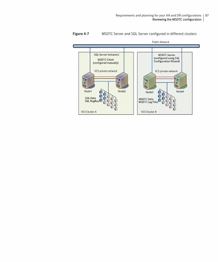
87Requirements and planning for your HA and DR configurationsReviewing the MSDTC configuration
Figure 4-7 MSDTC Server and SQL Server configured in different clusters
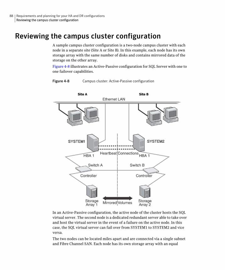
88 Requirements and planning for your HA and DR configurationsReviewing the campus cluster configuration
Reviewing the campus cluster configurationA sample campus cluster configuration is a two-node campus cluster with each node in a separate site (Site A or Site B). In this example, each node has its own storage array with the same number of disks and contains mirrored data of the storage on the other array.
Figure 4-8 illustrates an Active-Passive configuration for SQL Server with one to one failover capabilities.
Figure 4-8 Campus cluster: Active-Passive configuration
In an Active-Passive configuration, the active node of the cluster hosts the SQL virtual server. The second node is a dedicated redundant server able to take over and host the virtual server in the event of a failure on the active node. In this case, the SQL virtual server can fail over from SYSTEM1 to SYSTEM2 and vice versa.
The two nodes can be located miles apart and are connected via a single subnet and Fibre Channel SAN. Each node has its own storage array with an equal
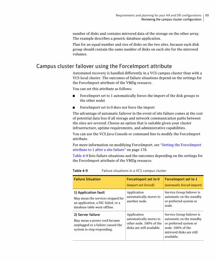
89Requirements and planning for your HA and DR configurationsReviewing the campus cluster configuration
number of disks and contains mirrored data of the storage on the other array. The example describes a generic database application.
Plan for an equal number and size of disks on the two sites, because each disk group should contain the same number of disks on each site for the mirrored volumes.
Campus cluster failover using the ForceImport attributeAutomated recovery is handled differently in a VCS campus cluster than with a VCS local cluster. The outcomes of failure situations depend on the settings for the ForceImport attribute of the VMDg resource.
You can set this attribute as follows:
■ ForceImport set to 1 automatically forces the import of the disk groups to the other node)
■ ForceImport set to 0 does not force the import
The advantage of automatic failover in the event of site failure comes at the cost of potential data loss if all storage and network communication paths between the sites are severed. Choose an option that is suitable given your cluster infrastructure, uptime requirements, and administrative capabilities.
You can use the VCS Java Console or command line to modify the ForceImport attribute.
For more information on modifying ForceImport, see “Setting the ForceImport attribute to 1 after a site failure” on page 178.
Table 4-9 lists failure situations and the outcomes depending on the settings for the ForceImport attribute of the VMDg resource.
Table 4-9 Failure situations in a VCS campus cluster
Failure Situation ForceImport set to 0
(import not forced)
ForceImport set to 1
(automatic forced import)
1) Application fault
May mean the services stopped for an application, a NIC failed, or a database table went offline.
Application automatically moves to another node.
Service Group failover is automatic on the standby or preferred system or node.
2) Server failure
May mean a power cord became unplugged or a failure caused the system to stop responding.
Application automatically moves to other node. 100% of the disks are still available.
Service Group failover is automatic on the standby or preferred system or node. 100% of the mirrored disks are still available.
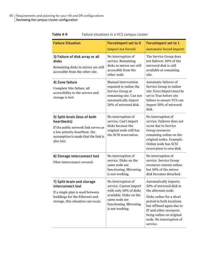
90 Requirements and planning for your HA and DR configurationsReviewing the campus cluster configuration
3) Failure of disk array or all disks
Remaining disks in mirror are still accessible from the other site.
No interruption of service. Remaining disks in mirror are still accessible from the other node.
The Service Group does not failover. 50% of the mirrored disk is still available at remaining site.
4) Zone failure
Complete Site failure, all accessibility to the servers and storage is lost.
Manual intervention required to online the Service Group at remaining site. Can not automatically import 50% of mirrored disk.
Automatic failover of Service Group to online site. Force Import must be set to True before site failure to ensure VCS can import 50% of mirrored disk.
5) Split-brain (loss of both heartbeats)
If the public network link serves as a low-priority heartbeat, the assumption is made that the link is also lost.
No interruption of service. Can’t import disks because the original node still has the SCSI reservation.
No interruption of service. Failover does not occur due to Service Group resources remaining online on the original nodes. Example: Online node has SCSI reservation to own disk.
6) Storage interconnect lost
Fibre interconnect severed.
No interruption of service. Disks on the same node are functioning. Mirroring is not working.
No interruption of service. Service Group resources remain online, but 50% of the mirror disk becomes detached.
7) Split-brain and storage interconnect lost
If a single pipe is used between buildings for the Ethernet and storage, this situation can occur.
No interruption of service. Cannot import with only 50% of disks available. Disks on the same node are functioning. Mirroring is not working.
Automatically imports 50% of mirrored disk to the alternate node.
Disks online for a short period in both locations but offlined again due to IP and other resources being online on original node. No interruption of service.
Table 4-9 Failure situations in a VCS campus cluster
Failure Situation ForceImport set to 0
(import not forced)
ForceImport set to 1
(automatic forced import)
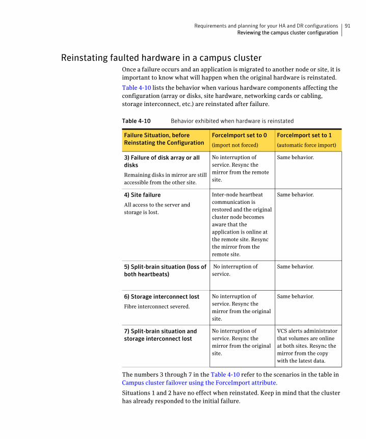
91Requirements and planning for your HA and DR configurationsReviewing the campus cluster configuration
Reinstating faulted hardware in a campus clusterOnce a failure occurs and an application is migrated to another node or site, it is important to know what will happen when the original hardware is reinstated.
Table 4-10 lists the behavior when various hardware components affecting the configuration (array or disks, site hardware, networking cards or cabling, storage interconnect, etc.) are reinstated after failure.
The numbers 3 through 7 in the Table 4-10 refer to the scenarios in the table in Campus cluster failover using the ForceImport attribute.
Situations 1 and 2 have no effect when reinstated. Keep in mind that the cluster has already responded to the initial failure.
Table 4-10 Behavior exhibited when hardware is reinstated
Failure Situation, before Reinstating the Configuration
ForceImport set to 0
(import not forced)
ForceImport set to 1
(automatic force import)
3) Failure of disk array or all disks
Remaining disks in mirror are still accessible from the other site.
No interruption of service. Resync the mirror from the remote site.
Same behavior.
4) Site failure
All access to the server and storage is lost.
Inter-node heartbeat communication is restored and the original cluster node becomes aware that the application is online at the remote site. Resync the mirror from the remote site.
Same behavior.
5) Split-brain situation (loss of both heartbeats)
No interruption of service.
Same behavior.
6) Storage interconnect lost
Fibre interconnect severed.
No interruption of service. Resync the mirror from the original site.
Same behavior.
7) Split-brain situation and storage interconnect lost
No interruption of service. Resync the mirror from the original site.
VCS alerts administrator that volumes are online at both sites. Resync the mirror from the copy with the latest data.
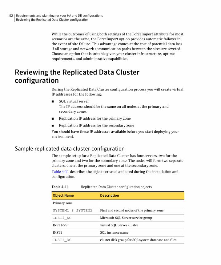
92 Requirements and planning for your HA and DR configurationsReviewing the Replicated Data Cluster configuration
While the outcomes of using both settings of the ForceImport attribute for most scenarios are the same, the ForceImport option provides automatic failover in the event of site failure. This advantage comes at the cost of potential data loss if all storage and network communication paths between the sites are severed. Choose an option that is suitable given your cluster infrastructure, uptime requirements, and administrative capabilities.
Reviewing the Replicated Data Cluster configuration
During the Replicated Data Cluster configuration process you will create virtual IP addresses for the following:
■ SQL virtual server
The IP address should be the same on all nodes at the primary and secondary zones.
■ Replication IP address for the primary zone
■ Replication IP address for the secondary zone
You should have these IP addresses available before you start deploying your environment.
Sample replicated data cluster configurationThe sample setup for a Replicated Data Cluster has four servers, two for the primary zone and two for the secondary zone. The nodes will form two separate clusters, one at the primary zone and one at the secondary zone.
Table 4-11 describes the objects created and used during the installation and configuration.
Table 4-11 Replicated Data Cluster configuration objects
Object Name Description
Primary zone
SYSTEM1 & SYSTEM2 First and second nodes of the primary zone
INST1_SG Microsoft SQL Server service group
INST1-VS virtual SQL Server cluster
INST1 SQL instance name
INST1_DG cluster disk group for SQL system database and files
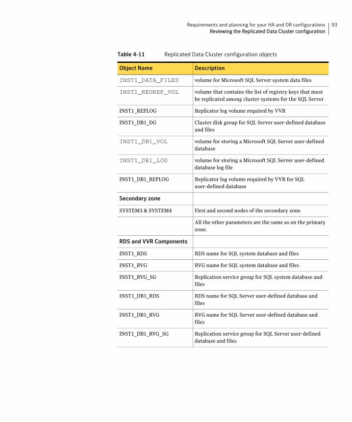
93Requirements and planning for your HA and DR configurationsReviewing the Replicated Data Cluster configuration
INST1_DATA_FILES volume for Microsoft SQL Server system data files
INST1_REGREP_VOL volume that contains the list of registry keys that must be replicated among cluster systems for the SQL Server
INST1_REPLOG Replicator log volume required by VVR
INST1_DB1_DG Cluster disk group for SQL Server user-defined database and files
INST1_DB1_VOL volume for storing a Microsoft SQL Server user-defined database
INST1_DB1_LOG volume for storing a Microsoft SQL Server user-defined database log file
INST1_DB1_REPLOG Replicator log volume required by VVR for SQL user-defined database
Secondary zone
SYSTEM3 & SYSTEM4 First and second nodes of the secondary zone
All the other parameters are the same as on the primary zone.
RDS and VVR Components
INST1_RDS RDS name for SQL system database and files
INST1_RVG RVG name for SQL system database and files
INST1_RVG_SG Replication service group for SQL system database and files
INST1_DB1_RDS RDS name for SQL Server user-defined database and files
INST1_DB1_RVG RVG name for SQL Server user-defined database and files
INST1_DB1_RVG_SG Replication service group for SQL Server user-defined database and files
Table 4-11 Replicated Data Cluster configuration objects
Object Name Description
94 Requirements and planning for your HA and DR configurationsAbout setting up a Replicated Data Cluster configuration
About setting up a Replicated Data Cluster configuration
In the example, SQL Server is configured as a VCS service group in a four-node cluster, with two nodes in the primary RDC zone and two in the secondary RDC zone. In the event of a failure on the primary node, VCS can fail over the SQL Server instance to the second node in the primary zone.
The process involves the steps described in the following topics:
■ About setting up replication
■ About configuring and migrating the service group
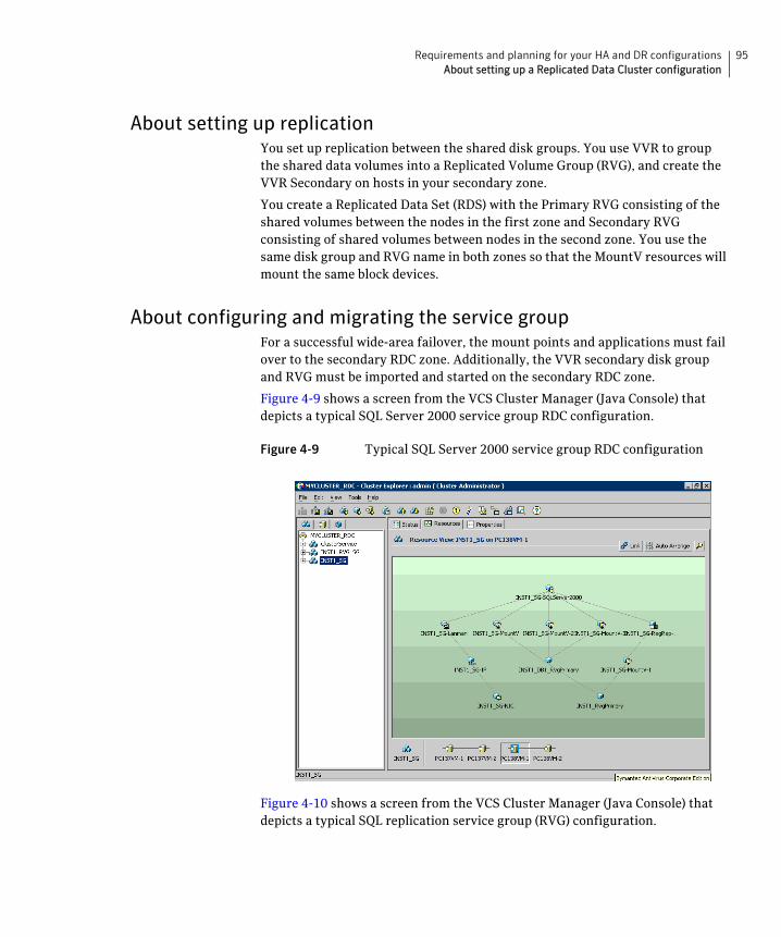
95Requirements and planning for your HA and DR configurationsAbout setting up a Replicated Data Cluster configuration
About setting up replicationYou set up replication between the shared disk groups. You use VVR to group the shared data volumes into a Replicated Volume Group (RVG), and create the VVR Secondary on hosts in your secondary zone.
You create a Replicated Data Set (RDS) with the Primary RVG consisting of the shared volumes between the nodes in the first zone and Secondary RVG consisting of shared volumes between nodes in the second zone. You use the same disk group and RVG name in both zones so that the MountV resources will mount the same block devices.
About configuring and migrating the service groupFor a successful wide-area failover, the mount points and applications must fail over to the secondary RDC zone. Additionally, the VVR secondary disk group and RVG must be imported and started on the secondary RDC zone.
Figure 4-9 shows a screen from the VCS Cluster Manager (Java Console) that depicts a typical SQL Server 2000 service group RDC configuration.
Figure 4-9 Typical SQL Server 2000 service group RDC configuration
Figure 4-10 shows a screen from the VCS Cluster Manager (Java Console) that depicts a typical SQL replication service group (RVG) configuration.
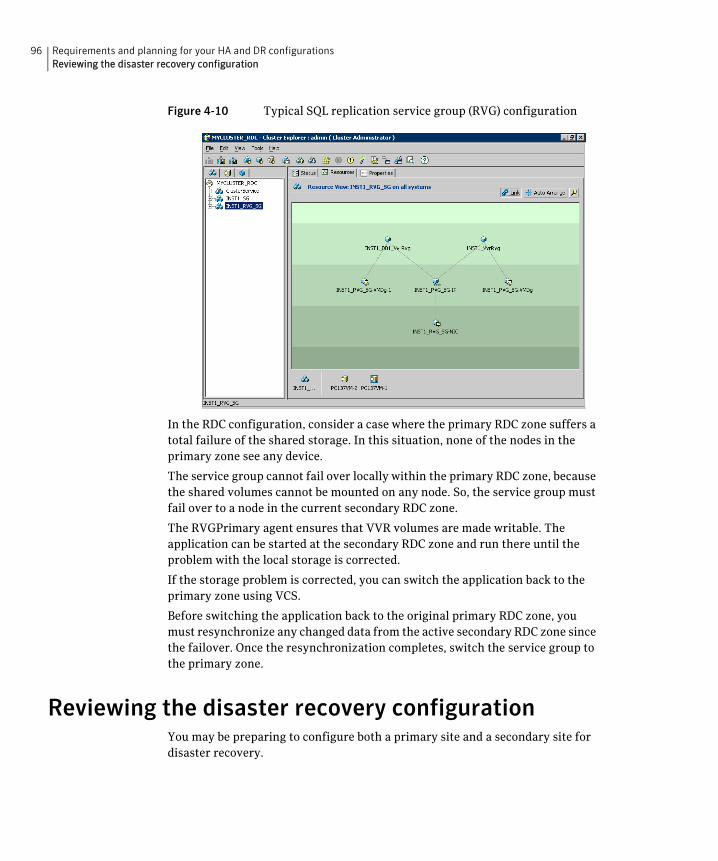
96 Requirements and planning for your HA and DR configurationsReviewing the disaster recovery configuration
Figure 4-10 Typical SQL replication service group (RVG) configuration
In the RDC configuration, consider a case where the primary RDC zone suffers a total failure of the shared storage. In this situation, none of the nodes in the primary zone see any device.
The service group cannot fail over locally within the primary RDC zone, because the shared volumes cannot be mounted on any node. So, the service group must fail over to a node in the current secondary RDC zone.
The RVGPrimary agent ensures that VVR volumes are made writable. The application can be started at the secondary RDC zone and run there until the problem with the local storage is corrected.
If the storage problem is corrected, you can switch the application back to the primary zone using VCS.
Before switching the application back to the original primary RDC zone, you must resynchronize any changed data from the active secondary RDC zone since the failover. Once the resynchronization completes, switch the service group to the primary zone.
Reviewing the disaster recovery configurationYou may be preparing to configure both a primary site and a secondary site for disaster recovery.
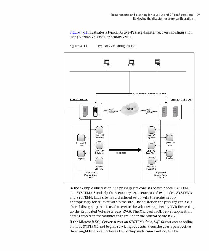
97Requirements and planning for your HA and DR configurationsReviewing the disaster recovery configuration
Figure 4-11 illustrates a typical Active-Passive disaster recovery configuration using Veritas Volume Replicator (VVR).
Figure 4-11 Typical VVR configuration
In the example illustration, the primary site consists of two nodes, SYSTEM1 and SYSTEM2. Similarly the secondary setup consists of two nodes, SYSTEM3 and SYSTEM4. Each site has a clustered setup with the nodes set up appropriately for failover within the site. The cluster on the primary site has a shared disk group that is used to create the volumes required by VVR for setting up the Replicated Volume Group (RVG). The Microsoft SQL Server application data is stored on the volumes that are under the control of the RVG.
If the Microsoft SQL Server server on SYSTEM1 fails, SQL Server comes online on node SYSTEM2 and begins servicing requests. From the user’s perspective there might be a small delay as the backup node comes online, but the
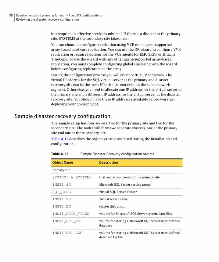
98 Requirements and planning for your HA and DR configurationsReviewing the disaster recovery configuration
interruption in effective service is minimal. If there is a disaster at the primary site, SYSTEM3 at the secondary site takes over.
You can choose to configure replication using VVR or an agent-supported array-based hardware replication. You can use the DR wizard to configure VVR replication or required options for the VCS agents for EMC SRDF or Hitachi TrueCopy. To use the wizard with any other agent-supported array-based replication, you must complete configuring global clustering with the wizard before configuring replication on the array.
During the configuration process you will create virtual IP addresses. The virtual IP address for the SQL virtual server at the primary and disaster recovery site can be the same if both sites can exist on the same network segment. Otherwise, you need to allocate one IP address for the virtual server at the primary site and a different IP address for the virtual server at the disaster recovery site. You should have these IP addresses available before you start deploying your environment.
Sample disaster recovery configurationThe sample setup has four servers, two for the primary site and two for the secondary site. The nodes will form two separate clusters, one at the primary site and one at the secondary site.
Table 4-12 describes the objects created and used during the installation and configuration.
Table 4-12 Sample Disaster Recovery configuration objects
Object Name Description
Primary site
SYSTEM1 & SYSTEM2 first and second nodes of the primary site
INST1_SG Microsoft SQL Server service group
SQL_CLUS1 virtual SQL Server cluster
INST1-VS virtual server name
INST1_DG cluster disk group
INST1_DATA_FILES volume for Microsoft SQL Server system data files
INST1_DB1_VOL volume for storing a Microsoft SQL Server user-defined database
INST1_DB1_LOG volume for storing a Microsoft SQL Server user-defined database log file
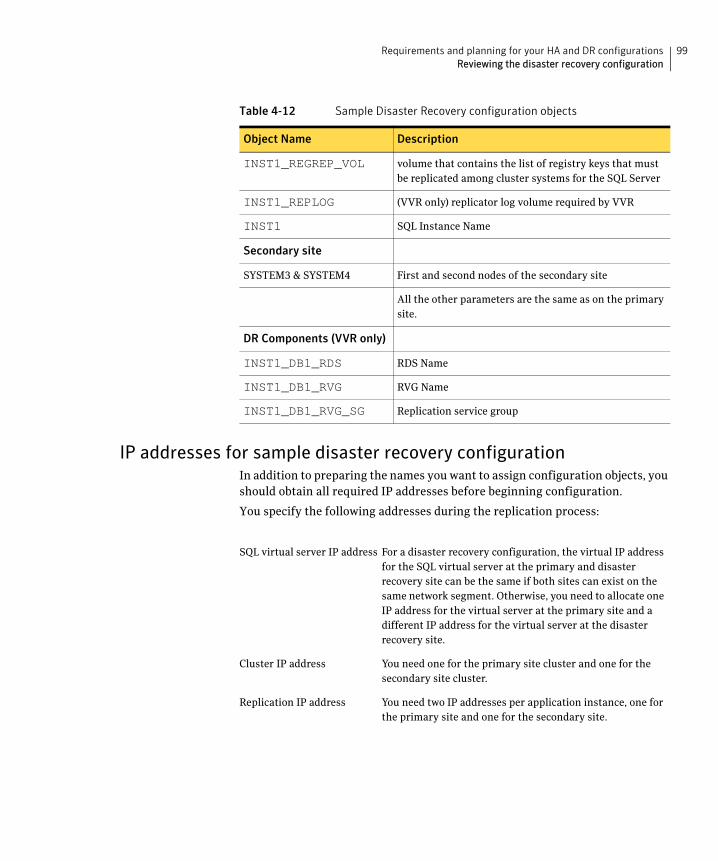
99Requirements and planning for your HA and DR configurationsReviewing the disaster recovery configuration
IP addresses for sample disaster recovery configurationIn addition to preparing the names you want to assign configuration objects, you should obtain all required IP addresses before beginning configuration.
You specify the following addresses during the replication process:
INST1_REGREP_VOL volume that contains the list of registry keys that must be replicated among cluster systems for the SQL Server
INST1_REPLOG (VVR only) replicator log volume required by VVR
INST1 SQL Instance Name
Secondary site
SYSTEM3 & SYSTEM4 First and second nodes of the secondary site
All the other parameters are the same as on the primary site.
DR Components (VVR only)
INST1_DB1_RDS RDS Name
INST1_DB1_RVG RVG Name
INST1_DB1_RVG_SG Replication service group
Table 4-12 Sample Disaster Recovery configuration objects
Object Name Description
SQL virtual server IP address For a disaster recovery configuration, the virtual IP address for the SQL virtual server at the primary and disaster recovery site can be the same if both sites can exist on the same network segment. Otherwise, you need to allocate one IP address for the virtual server at the primary site and a different IP address for the virtual server at the disaster recovery site.
Cluster IP address You need one for the primary site cluster and one for the secondary site cluster.
Replication IP address You need two IP addresses per application instance, one for the primary site and one for the secondary site.
100 Requirements and planning for your HA and DR configurationsReviewing the disaster recovery configuration
Supported disaster recovery configurations for service group dependencies
Service group dependencies have special requirements and limitations for disaster recovery configuration and for actions to be taken in a disaster recovery scenario.
Service group dependency configurations are described in detail in the VCS documentation.
See Veritas Cluster Server Administrator’s Guide.
For disaster recovery only certain dependent service group configurations are supported:
■ Online local soft
■ Online local firm
■ Online local hard
If the service group has an unsupported type of dependency and you select it in the DR wizard, you receive an error notification when you attempt to move to the next wizard page.
The Disaster Recovery wizard supports only one level of dependency (one child). In a VVR environment, the wizard configures a dependency for the RVG service group, so no other dependency is supported. If you need to configure more levels, you will need to add the service group and the dependency link manually on the secondary site after you finish running the DR wizard.
The wizard clones dependent service groups as global groups.
Section
4 DeploymentThis section contains the following chapters:
■ Installing and configuring SFW HA
■ Installing SQL Server
■ Configuring SQL Server for failover
■ Configuring campus clusters for SQL Server
■ Configuring Replicated Data Clusters for SQL Server
■ Configuring disaster recovery for SQL Server
■ Testing fault readiness by running a fire drill

102
Chapter
5Installing and configuring SFW HA
This chapter contains the following topics:
■ Configuring the storage hardware and network
■ Installing Veritas Storage Foundation HA for Windows
■ Configuring cluster disk groups and volumes for SQL Server
■ About managing disk groups and volumes
■ Configuring the cluster
104 Installing and configuring SFW HAConfiguring the storage hardware and network
Configuring the storage hardware and networkUse the following procedures to configure the hardware and verify DNS settings. Repeat this procedure for every node in the cluster.
To configure the hardware
1 Install the required network adapters, and SCSI controllers or Fibre Channel HBA.
2 Connect the network adapters on each system using the following guidelines:
■ To prevent lost heartbeats on the private networks, and to prevent VCS from mistakenly declaring a system down, Symantec recommends disabling the Ethernet autonegotiation options on the private network adapters. Contact the NIC manufacturer for details on this process.
■ Symantec recommends removing TCP/IP from private NICs to lower system overhead.
3 Use independent hubs or switches for each VCS communication network (GAB and LLT). You can use cross-over Ethernet cables for two-node clusters. LLT supports hub-based or switch network paths, or two-system clusters with direct network links.
4 Verify that each system can access the storage devices. Verify that each system recognizes the attached shared disk and that the attached shared disks are visible.
To verify the DNS settings and binding order
1 From the Control Panel, access the Network Connections window.
2 Ensure the public network adapter is the first bound adapter as follows:
■ From the Advanced menu, click Advanced Settings.
■ In the Adapters and Bindings tab, verify the public adapter is the first adapter in the Connections list. If necessary, use the arrow button to move the adapter to the top of the list.
3 Ensure that DNS name resolution is enabled. Make sure that you use the public network adapter, and not those configured for the private network.
Do the following:
■ In the Network Connections window, double-click the adapter for the public network to access its properties.
■ In the Public Status dialog box, on the General tab, click Properties.
105Installing and configuring SFW HAConfiguring the storage hardware and network
■ In the Public Properties dialog box, on the General tab, select the Internet Protocol (TCP/IP) check box and click Properties.
■ Select the Use the following DNS server addresses option and verify the correct value for the IP address of the DNS server.
■ Click Advanced.
■ In the DNS tab, make sure the Register this connection’s address in DNS check box is selected. Make sure the correct domain suffix is entered in the DNS suffix for this connection field.
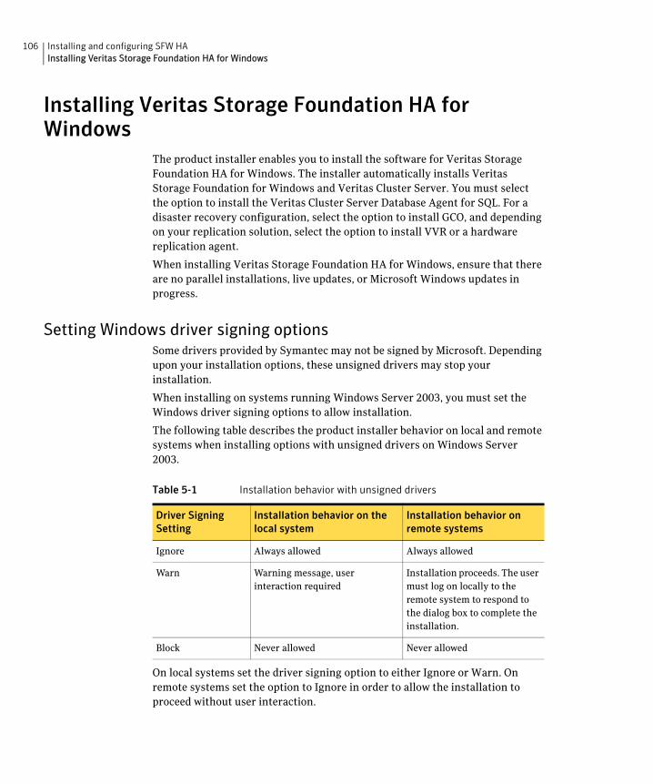
106 Installing and configuring SFW HAInstalling Veritas Storage Foundation HA for Windows
Installing Veritas Storage Foundation HA for Windows
The product installer enables you to install the software for Veritas Storage Foundation HA for Windows. The installer automatically installs Veritas Storage Foundation for Windows and Veritas Cluster Server. You must select the option to install the Veritas Cluster Server Database Agent for SQL. For a disaster recovery configuration, select the option to install GCO, and depending on your replication solution, select the option to install VVR or a hardware replication agent.
When installing Veritas Storage Foundation HA for Windows, ensure that there are no parallel installations, live updates, or Microsoft Windows updates in progress.
Setting Windows driver signing optionsSome drivers provided by Symantec may not be signed by Microsoft. Depending upon your installation options, these unsigned drivers may stop your installation.
When installing on systems running Windows Server 2003, you must set the Windows driver signing options to allow installation.
The following table describes the product installer behavior on local and remote systems when installing options with unsigned drivers on Windows Server 2003.
On local systems set the driver signing option to either Ignore or Warn. On remote systems set the option to Ignore in order to allow the installation to proceed without user interaction.
Table 5-1 Installation behavior with unsigned drivers
Driver Signing Setting
Installation behavior on the local system
Installation behavior on remote systems
Ignore Always allowed Always allowed
Warn Warning message, user interaction required
Installation proceeds. The user must log on locally to the remote system to respond to the dialog box to complete the installation.
Block Never allowed Never allowed
107Installing and configuring SFW HAInstalling Veritas Storage Foundation HA for Windows
Note: Windows Server 2008 does not allow you to change the driver signing option. Symantec provides an installation option to install a Symantec Trusted certificate to allow installation of Symantec drivers that are not certified by Microsoft. For details, see “Installing Symantec Trusted certificate for unsigned drivers” on page 107.
To change the driver signing options on each system
1 Log on locally to the system.
2 Open the Control Panel and click System.
3 Click the Hardware tab and click Driver Signing.
4 In the Driver Signing Options dialog box, note the current setting, and select Ignore or another option from the table that will allow installation to proceed.
5 Click OK.
6 Repeat for each computer.
If you do not change the driver signing option, the installation may fail on that computer during validation. After you complete the installation, reset the driver signing option to its previous state.
Installing Symantec Trusted certificate for unsigned drivers The product installer provides an installation option for Symantec Trusted Software Publisher Certificate for Veritas Storage Foundation for Windows drivers that are not certified by Microsoft.
If you select this installation option, a Symantec Trusted certificate is installed on the systems you select for installation.
Warning: On Windows Server 2008, if this option is not selected, a remote install will not install any SFW drivers that are not certified by Microsoft. No notification is given and it will appear that installation was successful, but issues can arise later because the drivers were not installed.
If installing locally on Windows Server 2008, if this option is not selected, a driver signing popup will be displayed requiring user interaction.
If you select this option when installing on Windows Server 2003, you do not need to set the driver signing options to Warn or Ignore.
108 Installing and configuring SFW HAInstalling Veritas Storage Foundation HA for Windows
Installing Storage Foundation HA for Windows Install Veritas Storage Foundation HA for Windows.
To install the product
1 Insert the DVD containing the installation software into your system’s disk drive or download the installation software from the Symantec website.
2 Allow the autorun feature to start the installation or double-click Setup.exe.
3 Review the links on the DVD browser panel.
The panel provides the Late Breaking News link to access the latest information about updates, patches, and software issues regarding this release, and a link to run the Configuration Checker to verify that your configurations meet all pertinent software and hardware requirements.
The panel provides links to install the software (Storage Foundation for Windows or Storage Foundation HA for Windows) and access the documentation (Getting Started Guide, Installation and Upgrade Guide, and Release Notes).
The panel also provides links to access the Veritas Operations Services (VOS) site (VOS provides you four types of detailed reports about your computer and Symantec enterprise products, a checklist of configuration recommendations, and system and patch requirements to install or upgrade your software), contact the Symantec Technical Support, and see the contents of the DVD.
4 Under Install Storage Foundation HA, do one of the following:
■ Click the Complete/Custom link to install server or client or both the components.
■ Click the Administrative Console link to install only the client components.
Note: With the Administrative Console option, you will not be prompted for a product license or presented with a list of product options for SFW or SFW HA.
Click the Complete/Custom link.
5 On the Welcome panel, review the Welcome message and the listed prerequisites. Ensure that the prerequisites are met prior to proceeding. Click Next.
6 On the License Agreement panel, read the license agreement. If you agree to the license terms, click I accept the terms of the License Agreement, and then click Next.
109Installing and configuring SFW HAInstalling Veritas Storage Foundation HA for Windows
7 On the License panel, enter the product license key before adding license keys for features. Click Enter license key(s), provide the license key in the field below it, and then click Add.
If you do not have a license key, click Use embedded evaluation license key to use the default evaluation license key. This license key is valid only for a limited evaluation period.
To remove a license key, click the key, and then click Remove. To see a license key’s details, click the key to display its details in the License key details area.
Click Next to continue.
8 On the Option Selection panel, select the appropriate SFW product options, and click Next.
9
10 On the System Selection panel, do the following, and then click Next:
■ To add a computer for installation, provide the name of the computer in the System Name box.
OR
If you do not know the name of the computer, click Browse to search for the computers available in your domain. The Select Systems dialog box appears. Select a computer from the Available Systems area, move it to the Selected Systems area, and then click OK to add it for installation.
■ To change the installation path of an added computer, click the folder icon for the computer, and then select the installation path in the Browse For Folder dialog box.
Veritas Cluster Server Data-base Agent for SQL
Required to configure high availability for SQL Server.
Client Components Required to install VCS Cluster Manager (Java console) and Veritas Enterprise Administrator console, which are used while configuring high availability.
Required to install the Solutions Configuration Center which provides information and wizards to assist configuration.
Global Cluster Option Required for a disaster recovery configuration only.
Volume Replicator (VVR) If you plan to use Veritas Volume Replicator (VVR) for replication, select this option to install VVR.
High Availability Hardware Replication Agents
If you plan to use hardware replication, select the appropriate hardware replication agent.
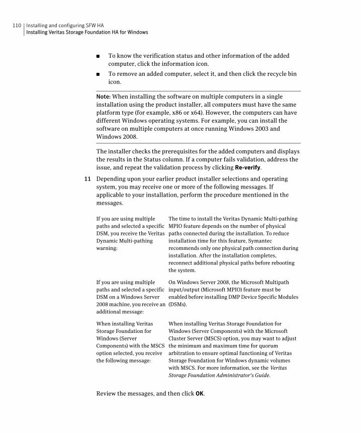
110 Installing and configuring SFW HAInstalling Veritas Storage Foundation HA for Windows
■ To know the verification status and other information of the added computer, click the information icon.
■ To remove an added computer, select it, and then click the recycle bin icon.
Note: When installing the software on multiple computers in a single installation using the product installer, all computers must have the same platform type (for example, x86 or x64). However, the computers can have different Windows operating systems. For example, you can install the software on multiple computers at once running Windows 2003 and Windows 2008.
The installer checks the prerequisites for the added computers and displays the results in the Status column. If a computer fails validation, address the issue, and repeat the validation process by clicking Re-verify.
11 Depending upon your earlier product installer selections and operating system, you may receive one or more of the following messages. If applicable to your installation, perform the procedure mentioned in the messages.
Review the messages, and then click OK.
If you are using multiple paths and selected a specific DSM, you receive the Veritas Dynamic Multi-pathing warning:
The time to install the Veritas Dynamic Multi-pathing MPIO feature depends on the number of physical paths connected during the installation. To reduce installation time for this feature, Symantec recommends only one physical path connection during installation. After the installation completes, reconnect additional physical paths before rebooting the system.
If you are using multiple paths and selected a specific DSM on a Windows Server 2008 machine, you receive an additional message:
On Windows Server 2008, the Microsoft Multipath input/output (Microsoft MPIO) feature must be enabled before installing DMP Device Specific Modules (DSMs).
When installing Veritas Storage Foundation for Windows (Server Components) with the MSCS option selected, you receive the following message:
When installing Veritas Storage Foundation for Windows (Server Components) with the Microsoft Cluster Server (MSCS) option, you may want to adjust the minimum and maximum time for quorum arbitration to ensure optimal functioning of Veritas Storage Foundation for Windows dynamic volumes with MSCS. For more information, see the Veritas Storage Foundation Administrator's Guide.
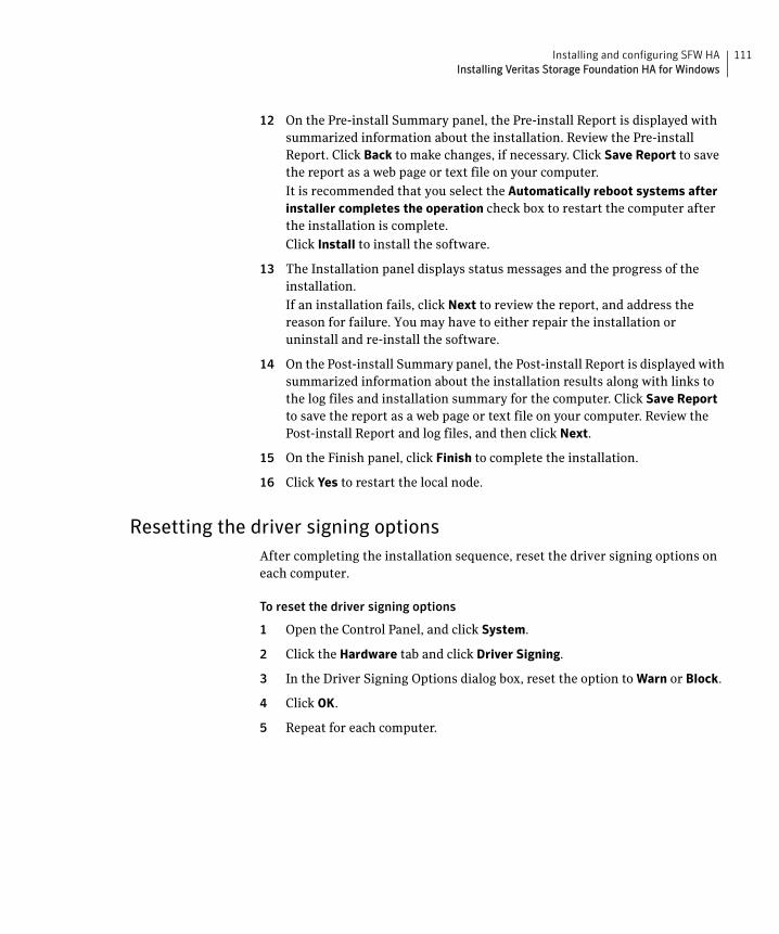
111Installing and configuring SFW HAInstalling Veritas Storage Foundation HA for Windows
12 On the Pre-install Summary panel, the Pre-install Report is displayed with summarized information about the installation. Review the Pre-install Report. Click Back to make changes, if necessary. Click Save Report to save the report as a web page or text file on your computer.
It is recommended that you select the Automatically reboot systems after installer completes the operation check box to restart the computer after the installation is complete.
Click Install to install the software.
13 The Installation panel displays status messages and the progress of the installation.
If an installation fails, click Next to review the report, and address the reason for failure. You may have to either repair the installation or uninstall and re-install the software.
14 On the Post-install Summary panel, the Post-install Report is displayed with summarized information about the installation results along with links to the log files and installation summary for the computer. Click Save Report to save the report as a web page or text file on your computer. Review the Post-install Report and log files, and then click Next.
15 On the Finish panel, click Finish to complete the installation.
16 Click Yes to restart the local node.
Resetting the driver signing optionsAfter completing the installation sequence, reset the driver signing options on each computer.
To reset the driver signing options
1 Open the Control Panel, and click System.
2 Click the Hardware tab and click Driver Signing.
3 In the Driver Signing Options dialog box, reset the option to Warn or Block.
4 Click OK.
5 Repeat for each computer.
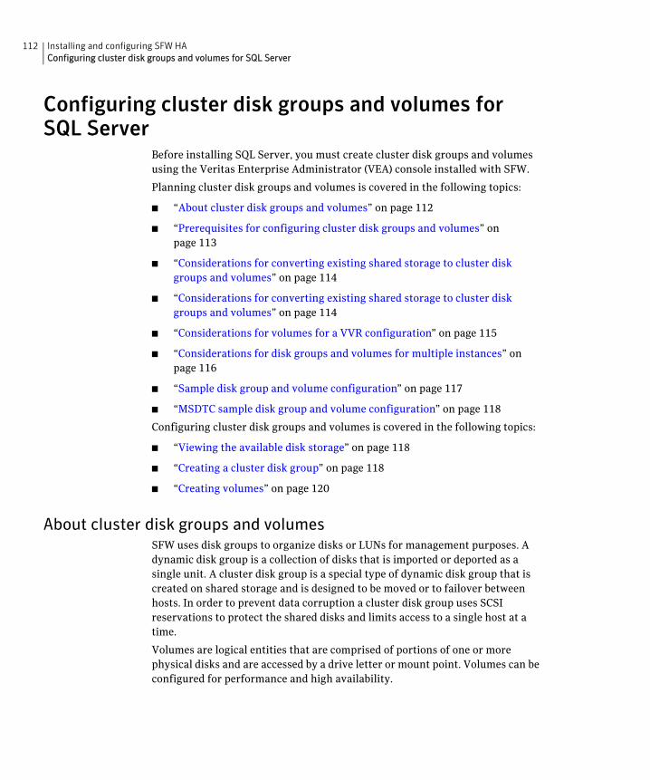
112 Installing and configuring SFW HAConfiguring cluster disk groups and volumes for SQL Server
Configuring cluster disk groups and volumes for SQL Server
Before installing SQL Server, you must create cluster disk groups and volumes using the Veritas Enterprise Administrator (VEA) console installed with SFW.
Planning cluster disk groups and volumes is covered in the following topics:
■ “About cluster disk groups and volumes” on page 112
■ “Prerequisites for configuring cluster disk groups and volumes” on page 113
■ “Considerations for converting existing shared storage to cluster disk groups and volumes” on page 114
■ “Considerations for converting existing shared storage to cluster disk groups and volumes” on page 114
■ “Considerations for volumes for a VVR configuration” on page 115
■ “Considerations for disk groups and volumes for multiple instances” on page 116
■ “Sample disk group and volume configuration” on page 117
■ “MSDTC sample disk group and volume configuration” on page 118
Configuring cluster disk groups and volumes is covered in the following topics:
■ “Viewing the available disk storage” on page 118
■ “Creating a cluster disk group” on page 118
■ “Creating volumes” on page 120
About cluster disk groups and volumesSFW uses disk groups to organize disks or LUNs for management purposes. A dynamic disk group is a collection of disks that is imported or deported as a single unit. A cluster disk group is a special type of dynamic disk group that is created on shared storage and is designed to be moved or to failover between hosts. In order to prevent data corruption a cluster disk group uses SCSI reservations to protect the shared disks and limits access to a single host at a time.
Volumes are logical entities that are comprised of portions of one or more physical disks and are accessed by a drive letter or mount point. Volumes can be configured for performance and high availability.
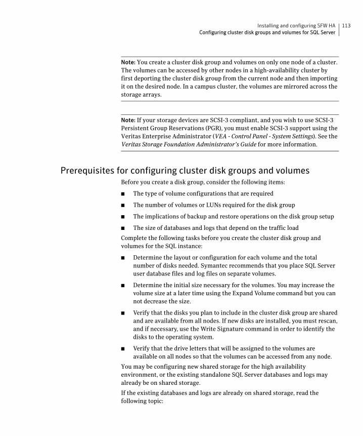
113Installing and configuring SFW HAConfiguring cluster disk groups and volumes for SQL Server
Note: You create a cluster disk group and volumes on only one node of a cluster. The volumes can be accessed by other nodes in a high-availability cluster by first deporting the cluster disk group from the current node and then importing it on the desired node. In a campus cluster, the volumes are mirrored across the storage arrays.
Note: If your storage devices are SCSI-3 compliant, and you wish to use SCSI-3 Persistent Group Reservations (PGR), you must enable SCSI-3 support using the Veritas Enterprise Administrator (VEA - Control Panel - System Settings). See the Veritas Storage Foundation Administrator’s Guide for more information.
Prerequisites for configuring cluster disk groups and volumesBefore you create a disk group, consider the following items:
■ The type of volume configurations that are required
■ The number of volumes or LUNs required for the disk group
■ The implications of backup and restore operations on the disk group setup
■ The size of databases and logs that depend on the traffic load
Complete the following tasks before you create the cluster disk group and volumes for the SQL instance:
■ Determine the layout or configuration for each volume and the total number of disks needed. Symantec recommends that you place SQL Server user database files and log files on separate volumes.
■ Determine the initial size necessary for the volumes. You may increase the volume size at a later time using the Expand Volume command but you can not decrease the size.
■ Verify that the disks you plan to include in the cluster disk group are shared and are available from all nodes. If new disks are installed, you must rescan, and if necessary, use the Write Signature command in order to identify the disks to the operating system.
■ Verify that the drive letters that will be assigned to the volumes are available on all nodes so that the volumes can be accessed from any node.
You may be configuring new shared storage for the high availability environment, or the existing standalone SQL Server databases and logs may already be on shared storage.
If the existing databases and logs are already on shared storage, read the following topic:
114 Installing and configuring SFW HAConfiguring cluster disk groups and volumes for SQL Server
■ “Considerations for converting existing shared storage to cluster disk groups and volumes” on page 114
For campus clusters, each disk group must contain an equal number of disks on each site. Each volume should be a mirrored volume with one plex of the volume on Site A’s storage array and the other plex of the volume on Site B’s storage array.
For more information on disk groups and volumes for campus clusters, read the following topic:
■ “Considerations for disks and volumes for campus clusters” on page 115
For a Replicated Data Cluster configuration or a disaster recovery configuration using Veritas Volume Replicator, read the following topic:
■ “Considerations for volumes for a VVR configuration” on page 115
Considerations for converting existing shared storage to cluster disk groups and volumes
The databases and logs for your existing standalone SQL Server may already be on shared storage. In this case, when you create cluster disk groups, you specify the disks that contain the existing databases and logs.
Creating a disk group converts the disks from basic disks to dynamic disks. Partitions on the disks are automatically converted to volumes on the dynamic disks.
Therefore, if your existing disk layout contains databases and logs in the same partition, they become part of the same volume in the cluster disk group. If the disk contains multiple partitions, each containing a user database, each partition becomes a separate volume, but all will become part of the same cluster disk group. If this configuration does not meet your requirements, you may want to modify your disk layout before creating the cluster disk group.
For additional information on converting basic to dynamic disks, see Veritas Storage Foundation Administrator’s Guide.
Symantec recommends creating a separate 100 MB RegRep volume that contains the list of registry keys that must be replicated among cluster systems for the SQL service. However, if no additional disks are available on the shared storage, you can specify an existing volume as the registry replication path during service group creation.
For a disaster recovery configuration using Veritas Volume Replicator, you need to allow additional disk space for a Storage Replicator Log volume.
See “Considerations for volumes for a VVR configuration” on page 115.
115Installing and configuring SFW HAConfiguring cluster disk groups and volumes for SQL Server
Considerations for disks and volumes for campus clustersEnsure that each disk group has the same number of disks on each site. Each volume must be a mirrored volume with one plex of the volume on Site A’s storage array and the other plex of the volume on Site B’s storage array.
While creating the dynamic disk groups and volumes at Site A, note carefully which disks and volumes are allocated. These will later become the Site A plexes for the mirrors.
Consider the following when creating new volumes:
■ For campus clusters, when creating a new volume, you must select the “mirrored across enclosures” option.
■ Choosing “Mirrored” and the “mirrored across” option without having two enclosures that meet requirements causes new volume creation to fail.
■ Logging can slow performance.
■ Symantec recommends using either simple mirrored (concatenated) or striped mirrored options for the new volumes. Striped mirrored gives you better performance compared to concatenated.
When selecting striped mirrored, select two columns in order to stripe one enclosure that is mirrored to the second enclosure.
■ You cannot selecting RAID-5 for mirroring.
■ Selecting “stripe across enclosures” is not recommended because then you need four enclosures, instead of two.
Considerations for volumes for a VVR configurationFor a configuration using Veritas Volume Replicator, either a disaster recovery configuration on a secondary site or a Replicated Data Cluster, note the following:
■ VVR does not support the following types of volumes:
■ SFW (software) RAID 5 volumes
■ Volumes with the Dirty Region Log (DRL)
■ Data Change Object (DCO)
■ Volumes with commas in the names
■ A configuration with VVR requires a Storage Replicator Log (SRL) volume for each disk group that contains volumes that are replicated. You can create the SRL volume when configuring the other volumes for the application or you can create it later when you set up replication. If you create it later, ensure that you allow sufficient disk space for this volume.
116 Installing and configuring SFW HAConfiguring cluster disk groups and volumes for SQL Server
For more about VVR planning, see the Veritas Volume Replicator, Administrator’s Guide.
■ Do not assign a drive letter to the Storage Replicator Log volume. This will limit access to that volume and avoid potential data corruption.
■ In a disaster recovery configuration, Symantec recommends that for replication considerations, you create a separate volume for tempdb, for example, INST1_TEMPDB, within the system database disk group. When you later configure replication for disaster recovery, you replicate that disk group but exclude the tempdb volume from the replication.
It would waste bandwidth to replicate tempdb because the data is transitory and is not needed for DR site recovery.
You can create the volume now and later, after the SQL installation is complete and before configuring replication, move tempdb to the volume.
See “Moving the tempdb database if using VVR for disaster recovery” on page 154.
Considerations for disk groups and volumes for multiple instancesFor an Active-Active configuration or other cases where you are setting up multiple SQL instances in the cluster, you create a separate set of cluster disk groups and volumes for each instance.
For example, if you have a Billing instance and a Payroll instance, you could create the following disk groups and volumes.
For the Billing instance, create the following:
For the Payroll Instance, create the following:
BILLING_DG a cluster disk group for the volumes related to the Billing instance
BILLING_DATA_FILES volume for the SQL Server system data files
BILLING_REGREP_VOL volume for the list of registry keys replicated among cluster nodes for the Billing instance
BILLING_DB1_VOL volume for the user database files
BILLING_DB1_LOG volume for the user database log files
PAYROLL_DG a cluster disk group for the volumes related to the Payroll instance
PAYROLL_DATA_FILES volume for the SQL Server system data files
117Installing and configuring SFW HAConfiguring cluster disk groups and volumes for SQL Server
You can choose either of the following:
■ Set up disk groups and volumes for all instances at one time.
■ Set up disk groups and volumes for the current instance only and complete all configuration steps for this instance. Then return to this step for the next instance.
Sample disk group and volume configurationFor an SFW HA solution, you first create a cluster disk group (INST1_DG) on shared disks and then create the following volumes:
■ INST1_DATA_FILES contains the SQL Server system data files (including the master, model, msdb, and tempdb databases)
■ INST1_REGREP_VOL contains the list of registry keys that must be replicated among cluster systems for the SQL service. Create a 100 MB volume for this purpose.
■ INST1_REPLOG contains the VVR Storage Replicator Log.
This is required only for a configuration that uses VVR replication, either a Replicated Data Cluster or a disaster recovery configuration using VVR. You can create this volume later while setting up replication.
You may want to place user database files in a separate cluster disk group from the system database files, for example, by creating INST1_SHARED_DG for system files and INST1_USER_DG for user database files. As a best practice, create a separate disk group and volumes for SQL Server user-defined database and files.
The following disk group and volumes may be created now or later in the configuration process:
■ INST1_DB1_DG is the disk group for the SQL Server user-defined database and files
■ INST1_DB1_VOL contains the user database files
■ INST1_DB1_LOG contains the user database log files
■ INST1_DB1_REPLOG contains the VVR Storage Replicator Log (required only for a configuration using VVR replication).
PAYROLL_REGREP_VOL volume for the list of registry keys replicated among cluster nodes for the Payroll instance
PAYROLL_DB1_VOL volume for the user database files
PAYROLL_DB1_LOG volume for the user database log files
118 Installing and configuring SFW HAConfiguring cluster disk groups and volumes for SQL Server
This configuration is a simple example. The recommended practice for disk groups and volume layout is dependent on your environment.
MSDTC sample disk group and volume configurationFor an MSDTC configuration, you will first need to create a cluster disk group (MSDTC_DG) on shared disks and then create the following volumes:
Viewing the available disk storageBefore creating disk groups and volumes you may want to view available disk storage.
To view the available disk storage
1 Open the VEA console by clicking Start > All Programs > Symantec > Veritas Storage Foundation > Veritas Enterprise Administrator and select a profile if prompted.
2 Click Connect to a Host or Domain.
3 In the Connect dialog box select the host name from the pull-down menu and click Connect.
To connect to the local system, select localhost. Provide the user name, password, and domain if prompted.
4 In the VEA configuration tree, expand hostname > StorageAgent and then click Disks.
The internal names for the disks that the current system can access for available storage are displayed, with names Harddisk1, Harddisk2, etc. The list includes both disks internal to the local system and any external storage that is available.
Creating a cluster disk groupUse the Veritas Enterprise Administrator (VEA) to create a cluster disk group on the first node where the SQL instance is being installed. Repeat the procedure if you want to create additional disk groups.
MSDTC_LOG contains the MSDTC log files
MSDTC_REGREP contains the list of registry keys that must be replicated among cluster systems for the MSDTC service group
Create a 100 MB volume for this purpose.
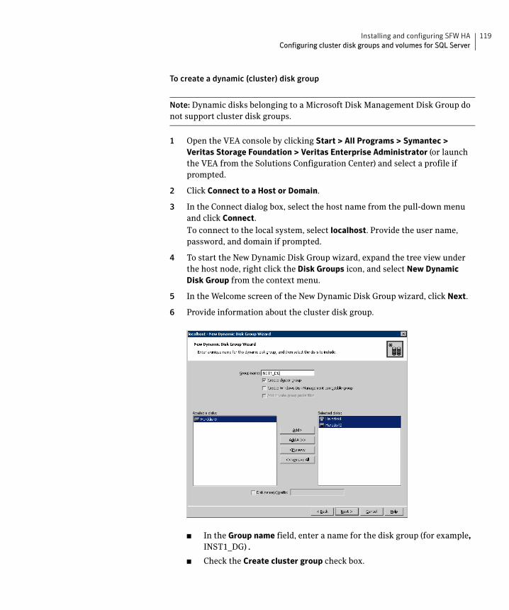
119Installing and configuring SFW HAConfiguring cluster disk groups and volumes for SQL Server
To create a dynamic (cluster) disk group
Note: Dynamic disks belonging to a Microsoft Disk Management Disk Group do not support cluster disk groups.
1 Open the VEA console by clicking Start > All Programs > Symantec > Veritas Storage Foundation > Veritas Enterprise Administrator (or launch the VEA from the Solutions Configuration Center) and select a profile if prompted.
2 Click Connect to a Host or Domain.
3 In the Connect dialog box, select the host name from the pull-down menu and click Connect.
To connect to the local system, select localhost. Provide the user name, password, and domain if prompted.
4 To start the New Dynamic Disk Group wizard, expand the tree view under the host node, right click the Disk Groups icon, and select New Dynamic Disk Group from the context menu.
5 In the Welcome screen of the New Dynamic Disk Group wizard, click Next.
6 Provide information about the cluster disk group.
■ In the Group name field, enter a name for the disk group (for example, INST1_DG).
■ Check the Create cluster group check box.
120 Installing and configuring SFW HAConfiguring cluster disk groups and volumes for SQL Server
■ Select the appropriate disks in the Available disks list, and use the Add button to move them to the Selected disks list.
Optionally, check the Disk names prefix checkbox and enter a disk name prefix to give the disks in the disk group a specific identifier.
For example, entering TestGroup as the prefix for a disk group that contains three disks creates TestGroup1, TestGroup2, and TestGroup3 as internal names for the disks in the disk group.
Note: For Windows Server 2003, Windows Disk Management Compatible Dynamic Disk Group creates a disk group that is compatible with the disk groups created with Windows Disk Management and with earlier versions of Volume Manager for Windows products.
■ Click Next.
7 Click Next to accept the confirmation screen with the selected disks.
8 Click Finish to create the new disk group.
Creating volumesThis procedure will guide you through the process of creating a volume on a cluster disk group. Repeat the procedure to create additional volumes.
Before you begin, review the following topics if applicable to your environment:
■ “Considerations for converting existing shared storage to cluster disk groups and volumes” on page 114
■ “Considerations for volumes for a VVR configuration” on page 115
Note: When assigning drive letters to volumes, ensure that the drive letters that you assign are available on all nodes.
To create dynamic volumes
1 If the VEA console is not already open, click Start > All Programs > Symantec > Veritas Storage Foundation > Veritas Enterprise Administrator and select a profile if prompted.
2 Click Connect to a Host or Domain.
3 In the Connect dialog box select the host name from the pull-down menu and click Connect.
To connect to the local system, select localhost. Provide the user name, password, and domain if prompted.
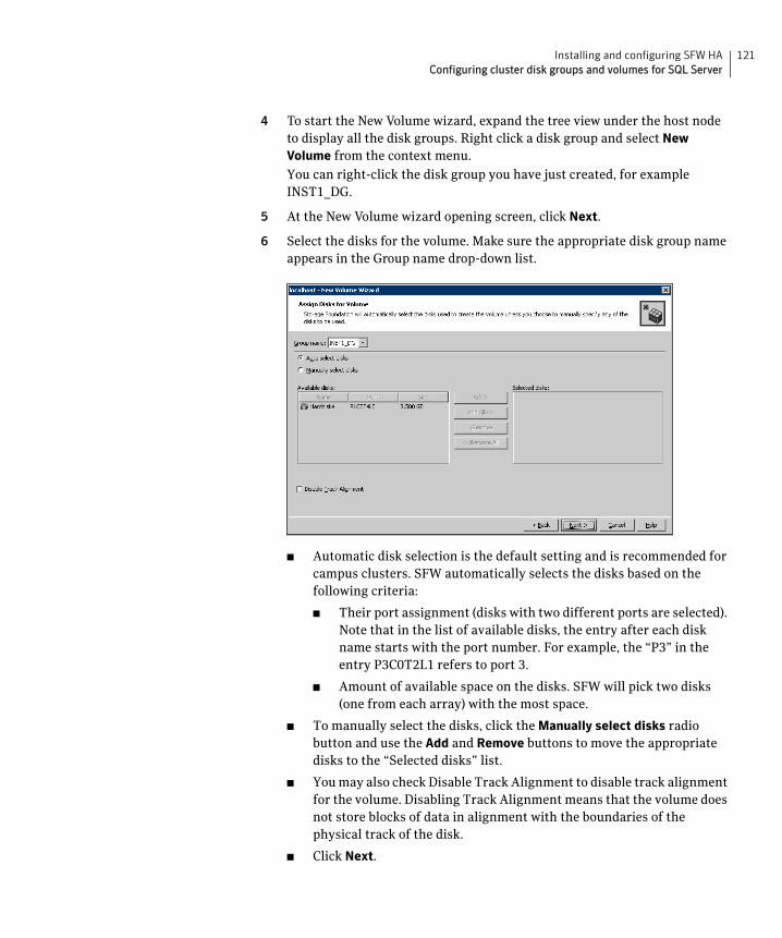
121Installing and configuring SFW HAConfiguring cluster disk groups and volumes for SQL Server
4 To start the New Volume wizard, expand the tree view under the host node to display all the disk groups. Right click a disk group and select New Volume from the context menu.
You can right-click the disk group you have just created, for example INST1_DG.
5 At the New Volume wizard opening screen, click Next.
6 Select the disks for the volume. Make sure the appropriate disk group name appears in the Group name drop-down list.
■ Automatic disk selection is the default setting and is recommended for campus clusters. SFW automatically selects the disks based on the following criteria:
■ Their port assignment (disks with two different ports are selected). Note that in the list of available disks, the entry after each disk name starts with the port number. For example, the “P3” in the entry P3C0T2L1 refers to port 3.
■ Amount of available space on the disks. SFW will pick two disks (one from each array) with the most space.
■ To manually select the disks, click the Manually select disks radio button and use the Add and Remove buttons to move the appropriate disks to the “Selected disks” list.
■ You may also check Disable Track Alignment to disable track alignment for the volume. Disabling Track Alignment means that the volume does not store blocks of data in alignment with the boundaries of the physical track of the disk.
■ Click Next.
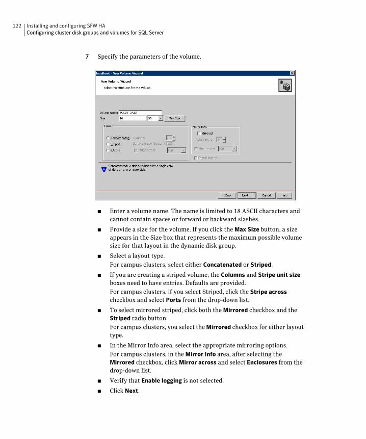
122 Installing and configuring SFW HAConfiguring cluster disk groups and volumes for SQL Server
7 Specify the parameters of the volume.
■ Enter a volume name. The name is limited to 18 ASCII characters and cannot contain spaces or forward or backward slashes.
■ Provide a size for the volume. If you click the Max Size button, a size appears in the Size box that represents the maximum possible volume size for that layout in the dynamic disk group.
■ Select a layout type.
For campus clusters, select either Concatenated or Striped.
■ If you are creating a striped volume, the Columns and Stripe unit size boxes need to have entries. Defaults are provided.
For campus clusters, if you select Striped, click the Stripe across checkbox and select Ports from the drop-down list.
■ To select mirrored striped, click both the Mirrored checkbox and the Striped radio button.
For campus clusters, you select the Mirrored checkbox for either layout type.
■ In the Mirror Info area, select the appropriate mirroring options.
For campus clusters, in the Mirror Info area, after selecting the Mirrored checkbox, click Mirror across and select Enclosures from the drop-down list.
■ Verify that Enable logging is not selected.
■ Click Next.
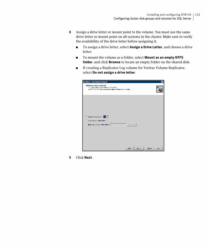
123Installing and configuring SFW HAConfiguring cluster disk groups and volumes for SQL Server
8 Assign a drive letter or mount point to the volume. You must use the same drive letter or mount point on all systems in the cluster. Make sure to verify the availability of the drive letter before assigning it.
■ To assign a drive letter, select Assign a Drive Letter, and choose a drive letter.
■ To mount the volume as a folder, select Mount as an empty NTFS folder, and click Browse to locate an empty folder on the shared disk.
■ If creating a Replicator Log volume for Veritas Volume Replicator, select Do not assign a drive letter.
9 Click Next.
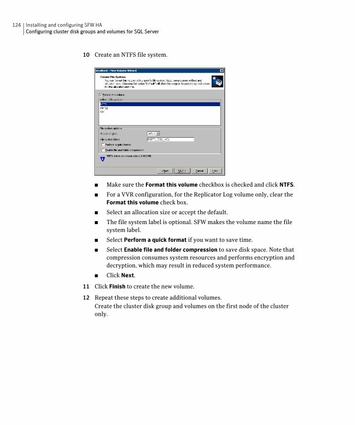
124 Installing and configuring SFW HAConfiguring cluster disk groups and volumes for SQL Server
10 Create an NTFS file system.
■ Make sure the Format this volume checkbox is checked and click NTFS.
■ For a VVR configuration, for the Replicator Log volume only, clear the Format this volume check box.
■ Select an allocation size or accept the default.
■ The file system label is optional. SFW makes the volume name the file system label.
■ Select Perform a quick format if you want to save time.
■ Select Enable file and folder compression to save disk space. Note that compression consumes system resources and performs encryption and decryption, which may result in reduced system performance.
■ Click Next.
11 Click Finish to create the new volume.
12 Repeat these steps to create additional volumes.
Create the cluster disk group and volumes on the first node of the cluster only.
125Installing and configuring SFW HAAbout managing disk groups and volumes
About managing disk groups and volumesDuring the process of setting up an SFW environment, refer to these general procedures for managing disk groups and volumes:
■ When a disk group is initially created, it is imported on the node where it is created.
■ A disk group can be imported on only one node at a time.
■ To move a disk group from one node to another, unmount the volumes in the disk group, deport the disk group from its current node, import it to a new node and mount the volumes.
Importing a disk group and mounting a volumeUse the VEA Console to import a disk group and mount a volume.
To import a disk group
1 From the VEA Console, right-click a disk name in a disk group or the group name in the Groups tab or tree view.
2 From the menu, click Import Dynamic Disk Group.
To mount a volume
1 If the disk group is not imported, import it.
2 To verify if a disk group is imported, from the VEA Console, click the Disks tab and check if the status is imported.
3 Right-click the volume, click File System, and click Change Drive Letter and Path.
4 Select one of the following options in the Drive Letter and Paths dialog box depending on whether you want to assign a drive letter to the volume or mount it as a folder.
■ To assign a drive letter
Select Assign a Drive Letter, and select a drive letter.
■ To mount the volume as a folder
Select Mount as an empty NTFS folder, and click Browse to locate an empty folder on the shared disk.
5 Click OK.
Unmounting a volume and deporting a disk groupUse the VEA Console to unmount a volume and deport a disk group.
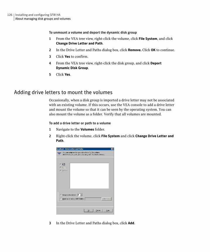
126 Installing and configuring SFW HAAbout managing disk groups and volumes
To unmount a volume and deport the dynamic disk group
1 From the VEA tree view, right-click the volume, click File System, and click Change Drive Letter and Path.
2 In the Drive Letter and Paths dialog box, click Remove. Click OK to continue.
3 Click Yes to confirm.
4 From the VEA tree view, right-click the disk group, and click Deport Dynamic Disk Group.
5 Click Yes.
Adding drive letters to mount the volumesOccasionally, when a disk group is imported a drive letter may not be associated with an existing volume. If this occurs, use the VEA console to add a drive letter and mount the volume so that it can be seen by the operating system. You can also mount the volume as a folder. Verify that all volumes are mounted.
To add a drive letter or path to a volume
1 Navigate to the Volumes folder.
2 Right-click the volume, click File System and click Change Drive Letter and Path.
3 In the Drive Letter and Paths dialog box, click Add.
127Installing and configuring SFW HAAbout managing disk groups and volumes
4 Select one of the following options depending on whether you want to assign a drive letter to the volume or mount it as a folder.
■ To assign a drive letter
Select the Assign a Drive Letter option and select a drive letter from the drop-down list.
■ To mount the volume as a folder
Select the Mount as an empty NTFS folder option and click Browse to locate an empty folder on the shared disk.
Note: Assign the same drive letter or mount path that was assigned when the volume was created.
5 Click OK.
Deporting the cluster disk groupBefore installing SQL on additional nodes you must move ownership of the cluster disk group from the first node to an additional node. To move ownership, you use the Veritas Enterprise Administrator (VEA) to deport the clustered cluster disk group from the current node (SYSTEM1) and then import it to the desired node (SYSTEM2).
To deport the cluster disk group
1 Stop all processes accessing the volumes in the cluster disk group.
2 Click Start > All Programs > Symantec > Veritas Enterprise Administrator and if prompted, select a profile.
3 Click Connect to a Host or Domain and in the Connect dialog box, specify the host name and click Connect.
4 In the tree view, expand the system name where the disk group is current imported, expand Storage Agent, and expand Disk Groups.
5 In the tree view, right-click the cluster disk group to be deported (for example, INST1_DG) and select Deport Dynamic Disk Group.
6 Click Yes to deport the dynamic cluster disk group.
128 Installing and configuring SFW HAConfiguring the cluster
Configuring the clusterThe VCS Cluster Configuration Wizard (VCW) sets up the cluster infrastructure, including LLT and GAB, and configures Symantec Product Authentication Service in the cluster. The wizard also provides the option to configure the ClusterService group, which can contain resources for Cluster Management Console (Single Cluster Mode) also referred to as Web Console, notification, and global clusters.
Complete the following tasks before creating a cluster:
■ Verify that each node uses static IP addresses and that name resolution is configured for each node.
■ Verify that you have the required privileges.
See “Reviewing the requirements” on page 68.
If you are setting up a cluster with multiple instances of SQL, plan to add all nodes for all instances to the cluster the first time that you run the wizard. If you do that, you do not need to run the wizard again later to add the nodes.
If you are setting up a Replicated Data Cluster configuration, add only the systems in the primary zone (zone 0) to the cluster, at this time.
Refer to the Veritas Cluster Server Administrator’s Guide for complete details on VCS, including instructions on adding cluster nodes or removing or modifying cluster configurations.
To configure a VCS cluster
1 Start the VCS Cluster Configuration Wizard.
Click Start > All Programs > Symantec > Veritas Cluster Server > Configuration Tools > Cluster Configuration Wizard.
2 Read the information on the Welcome panel and click Next.
3 On the Configuration Options panel, click Cluster Operations and click Next.
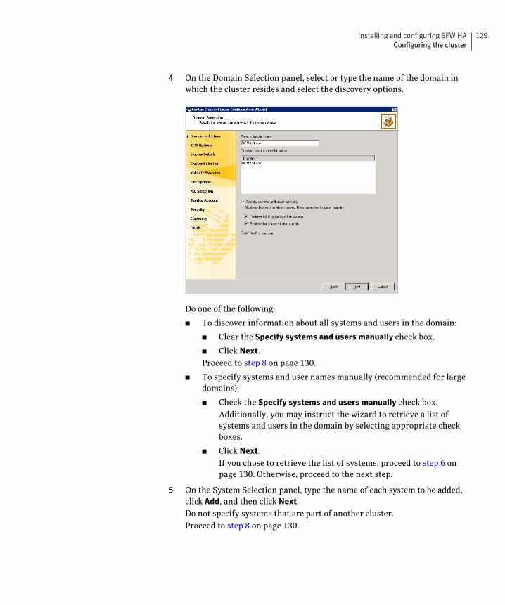
129Installing and configuring SFW HAConfiguring the cluster
4 On the Domain Selection panel, select or type the name of the domain in which the cluster resides and select the discovery options.
Do one of the following:
■ To discover information about all systems and users in the domain:
■ Clear the Specify systems and users manually check box.
■ Click Next.
Proceed to step 8 on page 130.
■ To specify systems and user names manually (recommended for large domains):
■ Check the Specify systems and users manually check box.
Additionally, you may instruct the wizard to retrieve a list of systems and users in the domain by selecting appropriate check boxes.
■ Click Next.
If you chose to retrieve the list of systems, proceed to step 6 on page 130. Otherwise, proceed to the next step.
5 On the System Selection panel, type the name of each system to be added, click Add, and then click Next.
Do not specify systems that are part of another cluster.
Proceed to step 8 on page 130.
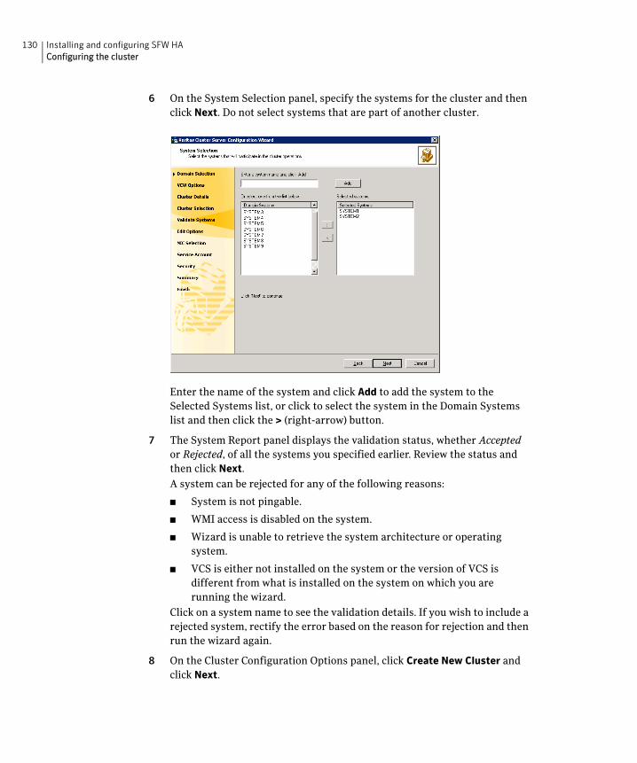
130 Installing and configuring SFW HAConfiguring the cluster
6 On the System Selection panel, specify the systems for the cluster and then click Next. Do not select systems that are part of another cluster.
Enter the name of the system and click Add to add the system to the Selected Systems list, or click to select the system in the Domain Systems list and then click the > (right-arrow) button.
7 The System Report panel displays the validation status, whether Accepted or Rejected, of all the systems you specified earlier. Review the status and then click Next.
A system can be rejected for any of the following reasons:
■ System is not pingable.
■ WMI access is disabled on the system.
■ Wizard is unable to retrieve the system architecture or operating system.
■ VCS is either not installed on the system or the version of VCS is different from what is installed on the system on which you are running the wizard.
Click on a system name to see the validation details. If you wish to include a rejected system, rectify the error based on the reason for rejection and then run the wizard again.
8 On the Cluster Configuration Options panel, click Create New Cluster and click Next.
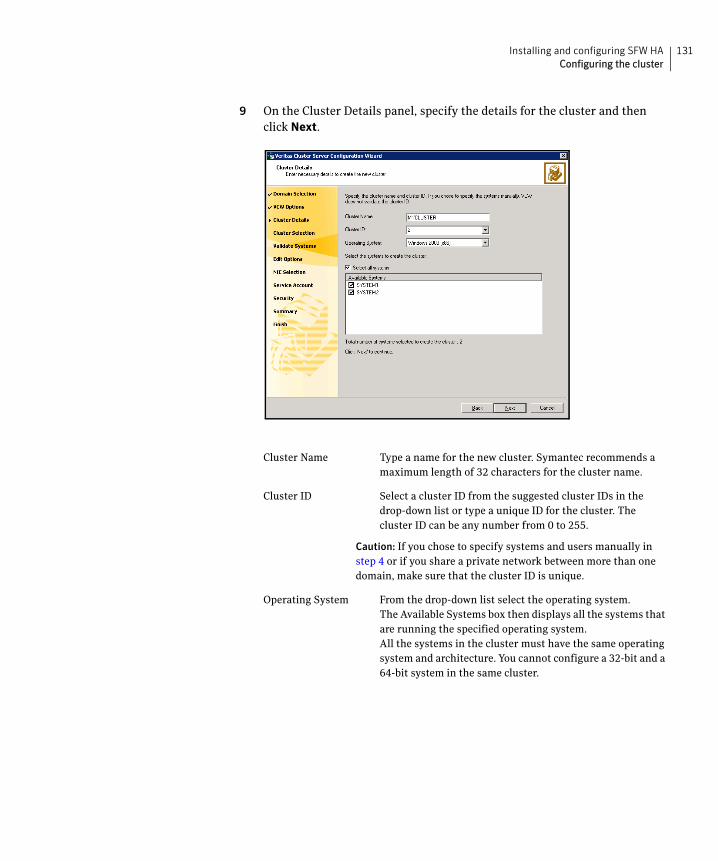
131Installing and configuring SFW HAConfiguring the cluster
9 On the Cluster Details panel, specify the details for the cluster and then click Next.
Cluster Name Type a name for the new cluster. Symantec recommends a maximum length of 32 characters for the cluster name.
Cluster ID Select a cluster ID from the suggested cluster IDs in the drop-down list or type a unique ID for the cluster. The cluster ID can be any number from 0 to 255.
Caution: If you chose to specify systems and users manually in step 4 or if you share a private network between more than one domain, make sure that the cluster ID is unique.
Operating System From the drop-down list select the operating system.The Available Systems box then displays all the systems that are running the specified operating system.All the systems in the cluster must have the same operating system and architecture. You cannot configure a 32-bit and a 64-bit system in the same cluster.
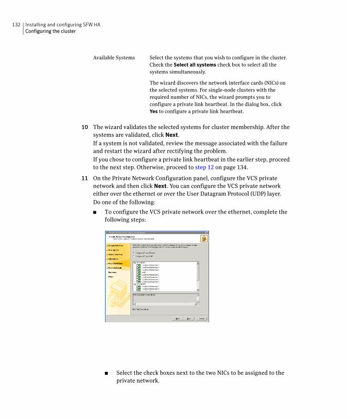
132 Installing and configuring SFW HAConfiguring the cluster
10 The wizard validates the selected systems for cluster membership. After the systems are validated, click Next.
If a system is not validated, review the message associated with the failure and restart the wizard after rectifying the problem.
If you chose to configure a private link heartbeat in the earlier step, proceed to the next step. Otherwise, proceed to step 12 on page 134.
11 On the Private Network Configuration panel, configure the VCS private network and then click Next. You can configure the VCS private network either over the ethernet or over the User Datagram Protocol (UDP) layer.
Do one of the following:
■ To configure the VCS private network over the ethernet, complete the following steps:
■ Select the check boxes next to the two NICs to be assigned to the private network.
Available Systems Select the systems that you wish to configure in the cluster.Check the Select all systems check box to select all the systems simultaneously.
The wizard discovers the network interface cards (NICs) on the selected systems. For single-node clusters with the required number of NICs, the wizard prompts you to configure a private link heartbeat. In the dialog box, click Yes to configure a private link heartbeat.
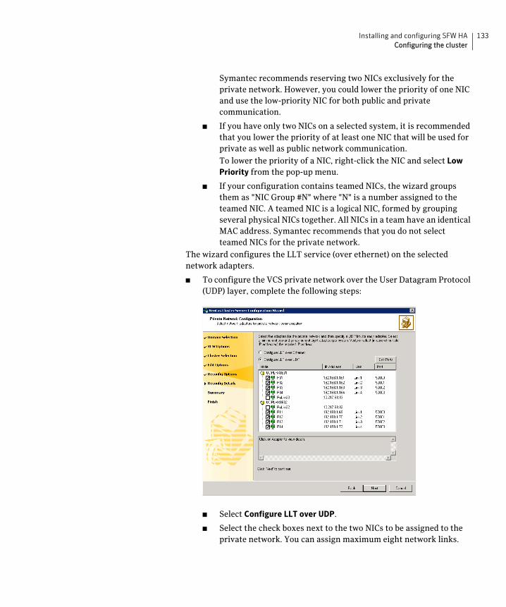
133Installing and configuring SFW HAConfiguring the cluster
Symantec recommends reserving two NICs exclusively for the private network. However, you could lower the priority of one NIC and use the low-priority NIC for both public and private communication.
■ If you have only two NICs on a selected system, it is recommended that you lower the priority of at least one NIC that will be used for private as well as public network communication.
To lower the priority of a NIC, right-click the NIC and select Low Priority from the pop-up menu.
■ If your configuration contains teamed NICs, the wizard groups them as "NIC Group #N" where "N" is a number assigned to the teamed NIC. A teamed NIC is a logical NIC, formed by grouping several physical NICs together. All NICs in a team have an identical MAC address. Symantec recommends that you do not select teamed NICs for the private network.
The wizard configures the LLT service (over ethernet) on the selected network adapters.
■ To configure the VCS private network over the User Datagram Protocol (UDP) layer, complete the following steps:
■ Select Configure LLT over UDP.
■ Select the check boxes next to the two NICs to be assigned to the private network. You can assign maximum eight network links.
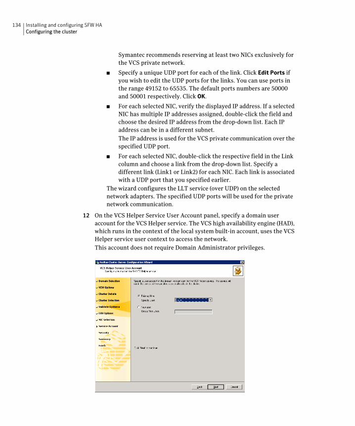
134 Installing and configuring SFW HAConfiguring the cluster
Symantec recommends reserving at least two NICs exclusively for the VCS private network.
■ Specify a unique UDP port for each of the link. Click Edit Ports if you wish to edit the UDP ports for the links. You can use ports in the range 49152 to 65535. The default ports numbers are 50000 and 50001 respectively. Click OK.
■ For each selected NIC, verify the displayed IP address. If a selected NIC has multiple IP addresses assigned, double-click the field and choose the desired IP address from the drop-down list. Each IP address can be in a different subnet.
The IP address is used for the VCS private communication over the specified UDP port.
■ For each selected NIC, double-click the respective field in the Link column and choose a link from the drop-down list. Specify a different link (Link1 or Link2) for each NIC. Each link is associated with a UDP port that you specified earlier.
The wizard configures the LLT service (over UDP) on the selected network adapters. The specified UDP ports will be used for the private network communication.
12 On the VCS Helper Service User Account panel, specify a domain user account for the VCS Helper service. The VCS high availability engine (HAD), which runs in the context of the local system built-in account, uses the VCS Helper service user context to access the network.
This account does not require Domain Administrator privileges.
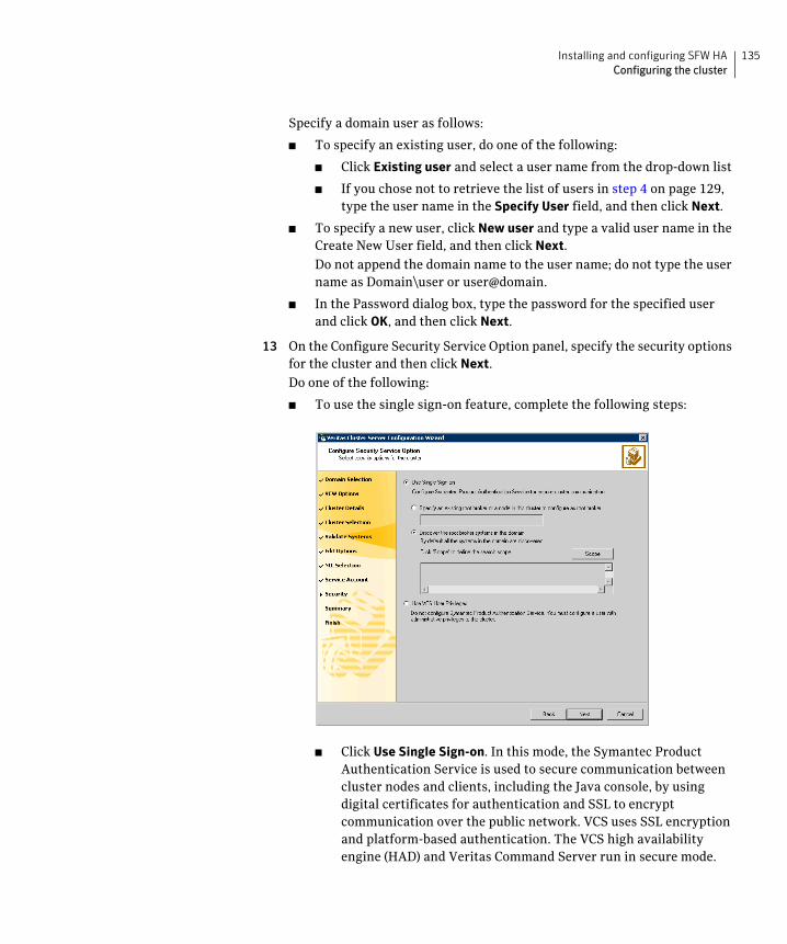
135Installing and configuring SFW HAConfiguring the cluster
Specify a domain user as follows:
■ To specify an existing user, do one of the following:
■ Click Existing user and select a user name from the drop-down list
■ If you chose not to retrieve the list of users in step 4 on page 129, type the user name in the Specify User field, and then click Next.
■ To specify a new user, click New user and type a valid user name in the Create New User field, and then click Next.
Do not append the domain name to the user name; do not type the user name as Domain\user or user@domain.
■ In the Password dialog box, type the password for the specified user and click OK, and then click Next.
13 On the Configure Security Service Option panel, specify the security options for the cluster and then click Next.
Do one of the following:
■ To use the single sign-on feature, complete the following steps:
■ Click Use Single Sign-on. In this mode, the Symantec Product Authentication Service is used to secure communication between cluster nodes and clients, including the Java console, by using digital certificates for authentication and SSL to encrypt communication over the public network. VCS uses SSL encryption and platform-based authentication. The VCS high availability engine (HAD) and Veritas Command Server run in secure mode.
136 Installing and configuring SFW HAConfiguring the cluster
For more information about secure communications in a cluster, see the Veritas Storage Foundation and High Availability Solutions Quick Start Guide for Symantec Product Authentication Service.
■ If you know the name of the system that will serve as the root broker, click Specify an existing root broker or a node in this cluster to configure as root broker, type the system name, and then click Next.
If you specify a cluster node, the wizard configures the node as the root broker and other nodes as authentication brokers. Authentication brokers reside one level below the root broker and serve as intermediate registration and certification authorities. These brokers can authenticate clients, such as users or services, but cannot authenticate other brokers. Authentication brokers have certificates signed by the root.
If you specify a system outside of the cluster, make sure that the system is configured as a root broker; the wizard then configures all nodes in the cluster as authentication brokers.
■ If you want to search the system that will serve as root broker, click Discover the root broker systems in the domain and click Next. The wizard will discover root brokers in the entire domain, by default.
■ If you want to define a search criteria, click Scope. In the Scope of Discovery dialog box, click Entire Domain to search across the domain, or click Specify Scope and select the Organization Unit from the Available Organizational Units list, to limit the search to the specified organization unit. Use the Filter Criteria options to search systems matching a certain condition.
For example, to search for systems managed by a user Administrator, select Managed by from the first drop-down list, is (exactly) from the second drop-down list, type the user name Administrator in the adjacent field, click Add, and then click OK.
To search for all Windows Server 2003 systems, select Operating System from the first drop-down list, is (exactly) from the second drop-down list, type *2003* in the adjacent field, click Add and then click OK.
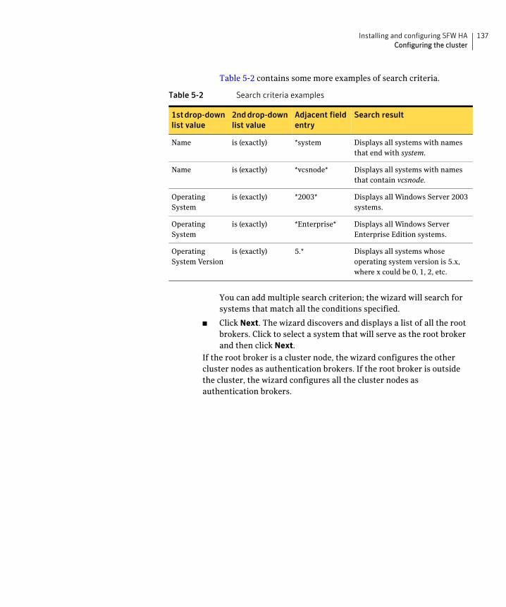
137Installing and configuring SFW HAConfiguring the cluster
Table 5-2 contains some more examples of search criteria.
You can add multiple search criterion; the wizard will search for systems that match all the conditions specified.
■ Click Next. The wizard discovers and displays a list of all the root brokers. Click to select a system that will serve as the root broker and then click Next.
If the root broker is a cluster node, the wizard configures the other cluster nodes as authentication brokers. If the root broker is outside the cluster, the wizard configures all the cluster nodes as authentication brokers.
Table 5-2 Search criteria examples
1st drop-down list value
2nd drop-down list value
Adjacent field entry
Search result
Name is (exactly) *system Displays all systems with names that end with system.
Name is (exactly) *vcsnode* Displays all systems with names that contain vcsnode.
Operating System
is (exactly) *2003* Displays all Windows Server 2003 systems.
Operating System
is (exactly) *Enterprise* Displays all Windows Server Enterprise Edition systems.
Operating System Version
is (exactly) 5.* Displays all systems whose operating system version is 5.x, where x could be 0, 1, 2, etc.
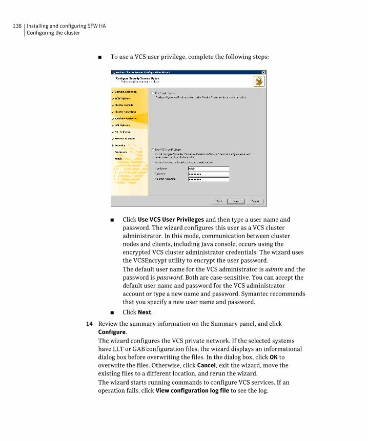
138 Installing and configuring SFW HAConfiguring the cluster
■ To use a VCS user privilege, complete the following steps:
■ Click Use VCS User Privileges and then type a user name and password. The wizard configures this user as a VCS cluster administrator. In this mode, communication between cluster nodes and clients, including Java console, occurs using the encrypted VCS cluster administrator credentials. The wizard uses the VCSEncrypt utility to encrypt the user password.
The default user name for the VCS administrator is admin and the password is password. Both are case-sensitive. You can accept the default user name and password for the VCS administrator account or type a new name and password. Symantec recommends that you specify a new user name and password.
■ Click Next.
14 Review the summary information on the Summary panel, and click Configure.
The wizard configures the VCS private network. If the selected systems have LLT or GAB configuration files, the wizard displays an informational dialog box before overwriting the files. In the dialog box, click OK to overwrite the files. Otherwise, click Cancel, exit the wizard, move the existing files to a different location, and rerun the wizard.
The wizard starts running commands to configure VCS services. If an operation fails, click View configuration log file to see the log.
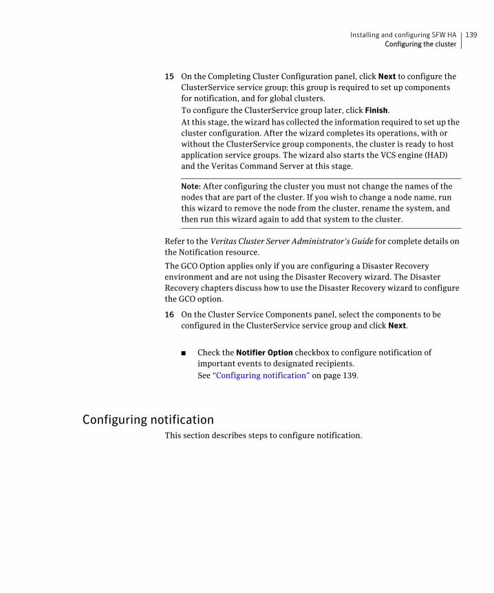
139Installing and configuring SFW HAConfiguring the cluster
15 On the Completing Cluster Configuration panel, click Next to configure the ClusterService service group; this group is required to set up components for notification, and for global clusters.
To configure the ClusterService group later, click Finish.
At this stage, the wizard has collected the information required to set up the cluster configuration. After the wizard completes its operations, with or without the ClusterService group components, the cluster is ready to host application service groups. The wizard also starts the VCS engine (HAD) and the Veritas Command Server at this stage.
Note: After configuring the cluster you must not change the names of the nodes that are part of the cluster. If you wish to change a node name, run this wizard to remove the node from the cluster, rename the system, and then run this wizard again to add that system to the cluster.
Refer to the Veritas Cluster Server Administrator’s Guide for complete details on the Notification resource.
The GCO Option applies only if you are configuring a Disaster Recovery environment and are not using the Disaster Recovery wizard. The Disaster Recovery chapters discuss how to use the Disaster Recovery wizard to configure the GCO option.
16 On the Cluster Service Components panel, select the components to be configured in the ClusterService service group and click Next.
■ Check the Notifier Option checkbox to configure notification of important events to designated recipients.
See “Configuring notification” on page 139.
Configuring notificationThis section describes steps to configure notification.
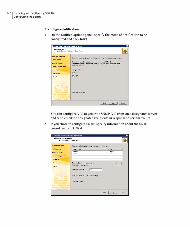
140 Installing and configuring SFW HAConfiguring the cluster
To configure notification
1 On the Notifier Options panel, specify the mode of notification to be configured and click Next.
You can configure VCS to generate SNMP (V2) traps on a designated server and send emails to designated recipients in response to certain events.
2 If you chose to configure SNMP, specify information about the SNMP console and click Next.
141Installing and configuring SFW HAConfiguring the cluster
■ Click a field in the SNMP Console column and type the name or IP address of the console. The specified SNMP console must be MIB 2.0 compliant.
■ Click the corresponding field in the Severity column and select a severity level for the console.
■ Click ‘+’ to add a field; click ‘-’ to remove a field.
■ Enter an SNMP trap port. The default value is “162”.
3 If you chose to configure SMTP, specify information about SMTP recipients and click Next.
■ Type the name of the SMTP server.
■ Click a field in the Recipients column and enter a recipient for notification. Enter recipients as [email protected].
■ Click the corresponding field in the Severity column and select a severity level for the recipient. VCS sends messages of an equal or higher severity to the recipient.
■ Click + to add fields; click - to remove a field.
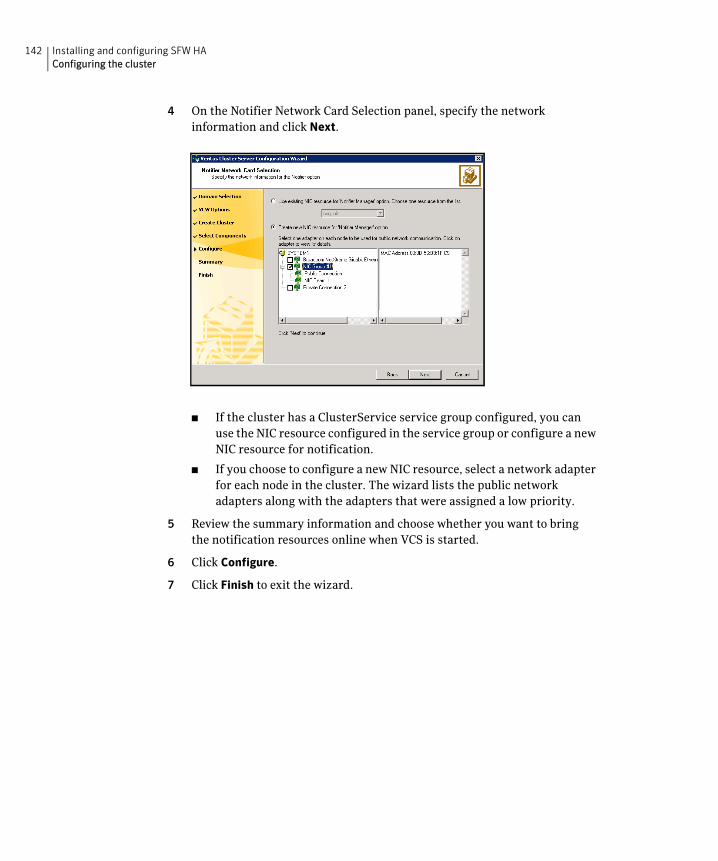
142 Installing and configuring SFW HAConfiguring the cluster
4 On the Notifier Network Card Selection panel, specify the network information and click Next.
■ If the cluster has a ClusterService service group configured, you can use the NIC resource configured in the service group or configure a new NIC resource for notification.
■ If you choose to configure a new NIC resource, select a network adapter for each node in the cluster. The wizard lists the public network adapters along with the adapters that were assigned a low priority.
5 Review the summary information and choose whether you want to bring the notification resources online when VCS is started.
6 Click Configure.
7 Click Finish to exit the wizard.
Chapter
6Installing SQL Server
This chapter contains the following topics:
■ About installing multiple SQL instances
■ Verifying that SQL Server databases and logs are moved to shared storage
■ “Installing and configuring SQL Server 2000 on the first cluster node” on page 144
■ “Installing and configuring SQL Server 2005 on the first cluster node” on page 147
■ Installing SQL Server on the second cluster node
■ “Setting the internal name of the clustered instance for SQL Server 2000” on page 151
■ Creating a SQL Server user-defined database
■ Completing configuration steps in SQL Server
About installing multiple SQL instancesIf you are installing multiple instances of SQL Server on the same system, as in an active-active cluster configuration, some additional requirements apply. The following summary is provided for your review to assist you in planning the installation:
■ Symantec recommends that you follow all steps for installing and setting up high availability for the first instance before you begin installing the next instance.
■ Assign a unique name and a unique instance ID to each SQL instance. When installing SQL Server on additional nodes for the same instance, ensure that you specify the same instance name and ID.
144 Installing SQL ServerVerifying that SQL Server databases and logs are moved to shared storage
■ Multiple instances of SQL Server must be installed in the same order on every node in the cluster. For example, if you install INST1 on SYSTEM1 and then on SYSTEM2, then install INST2 on SYSTEM1 and then on SYSTEM2.
■ Assign a unique port number for each instance.
Verifying that SQL Server databases and logs are moved to shared storage
This task is applicable only if you are configuring an existing standalone SQL Server in an SFW HA environment.
Verify the location of all SQL Server databases and logs for the existing standalone server. If they are located on local storage, move them from the local drive to the appropriate cluster disk groups and volumes on shared storage to ensure proper failover operations in the cluster.
Complete the following tasks to move the databases.
To move the database and logs to shared storage
1 Stop the SQL Server service.
2 Verify that you have backed up your existing data.
3 Create the required disk group and volumes for the SQL database and ensure that the dynamic disk group is imported on the node where the original database files are located on the local drives, and mount the volumes.
See the following topics:
“Creating a cluster disk group” on page 118
“Creating volumes” on page 120
“Deporting the cluster disk group” on page 127
“Importing a disk group and mounting a volume” on page 125
“Adding drive letters to mount the volumes” on page 126
4 Move the SQL Server data file and user database locations.
Refer to the Microsoft SQL Server documentation for instructions.
5 Restart SQL Server.
Installing and configuring SQL Server 2000 on the first cluster node
Run the Microsoft SQL Server installer to install SQL Server on the first cluster node. Refer to the Microsoft documentation for instructions.
145Installing SQL ServerInstalling and configuring SQL Server 2000 on the first cluster node
If you are configuring a standalone SQL Server, proceed to installing and configuring SQL on additional nodes.
See “Installing SQL Server on the second cluster node” on page 149.
Install the SQL program files to a local disk and the SQL data files to the shared storage managed by the cluster disk group. As you progress through the installation, use the following guidelines to create an installation that will function properly in your environment.
Note: Only the portions of the SQL Server installation procedure relevant to the SFW environment are documented. Refer to the Microsoft SQL Server 2000 documentation for detailed installation information. Also refer to the Microsoft SQL Server 2000 documentation on the use of /PAE and /AWE switches if you are installing multiple instances of SQL and anticipate intensive memory use.
To install Microsoft SQL Server 2000
1 From the browser menu, select SQL Server 2000 Components > Install Database Server. Proceed with the installation steps.
2 If you are running Windows Server 2003, click Continue at the message that says SQL Server 2000 SP2 and below is not supported by this version of Windows. You will install SQL Server 2000 SP4 after installing SQL Server.
3 On the Welcome screen, click Next.
4 In the Computer Name panel, select Local Computer and click Next.
5 Proceed through the installation to the Installation Definition panel.
6 In the Installation Definition panel, choose the Server and Client Tools option and click Next.
7 In the Instance Name panel, enter an instance name (for example INST1), and click Next.
Use the same instance name when installing this instance of SQL Server 2000 on failover nodes. If you are installing multiple instances of SQL in the cluster, each must have its own unique instance name.
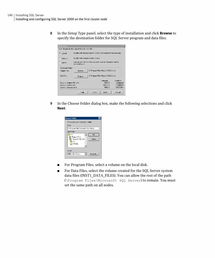
146 Installing SQL ServerInstalling and configuring SQL Server 2000 on the first cluster node
8 In the Setup Type panel, select the type of installation and click Browse to specify the destination folder for SQL Server program and data files.
9 In the Choose Folder dialog box, make the following selections and click Next:
■ For Program Files, select a volume on the local disk.
■ For Data Files, select the volume created for the SQL Server system data files (INST1_DATA_FILES). You can allow the rest of the path (\Program Files\Microsoft SQL Server) to remain. You must set the same path on all nodes.
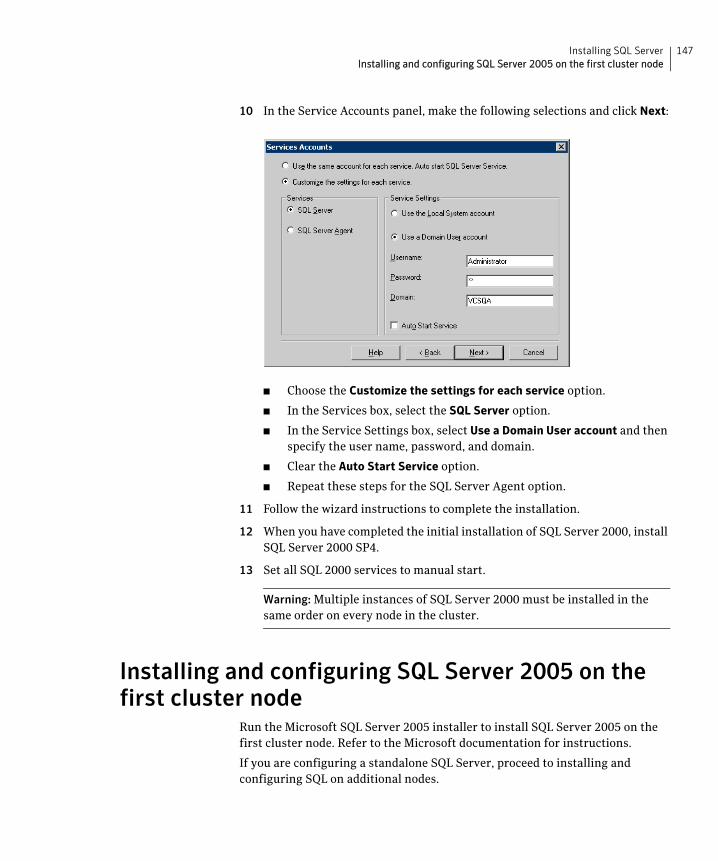
147Installing SQL ServerInstalling and configuring SQL Server 2005 on the first cluster node
10 In the Service Accounts panel, make the following selections and click Next:
■ Choose the Customize the settings for each service option.
■ In the Services box, select the SQL Server option.
■ In the Service Settings box, select Use a Domain User account and then specify the user name, password, and domain.
■ Clear the Auto Start Service option.
■ Repeat these steps for the SQL Server Agent option.
11 Follow the wizard instructions to complete the installation.
12 When you have completed the initial installation of SQL Server 2000, install SQL Server 2000 SP4.
13 Set all SQL 2000 services to manual start.
Warning: Multiple instances of SQL Server 2000 must be installed in the same order on every node in the cluster.
Installing and configuring SQL Server 2005 on the first cluster node
Run the Microsoft SQL Server 2005 installer to install SQL Server 2005 on the first cluster node. Refer to the Microsoft documentation for instructions.
If you are configuring a standalone SQL Server, proceed to installing and configuring SQL on additional nodes.
148 Installing SQL ServerInstalling and configuring SQL Server 2005 on the first cluster node
See “Installing SQL Server on the second cluster node” on page 149.
Note the following requirements while installing and configuring SQL Server:
■ Ensure that the cluster disk group is imported and the volumes are mounted to the first node for this SQL instance.
See “About cluster disk groups and volumes” on page 112.
See “Deporting the cluster disk group” on page 127.
See “Importing a disk group and mounting a volume” on page 125.
See “Adding drive letters to mount the volumes” on page 126.
■ Before you begin installing SQL Server 2005, verify that Microsoft Internet Information Services (IIS) is installed and enabled on the system. Otherwise, you will be prompted to install or enable IIS and then restart the installation.
■ Install the SQL program files to a local disk and the SQL database files to the shared storage managed by the cluster disk group.
■ Use the same instance name and instance ID when you install the instance of SQL Server on failover nodes. If you are installing multiple instances of SQL in the cluster, each instance must have a unique instance name and instance ID on all the nodes.
■ While specifying a user name for the SQL Server services account, specify a domain user account.
If SQL Server services are not installed with a domain user account, the SQL service group may fail to come online on the cluster nodes. It may come online only on the node on which SQL Server was installed last. In such a case, you must perform additional steps after configuring the SQL service group. See Technote http://support.veritas.com/docs/281828.
■ Apart from the SQL Browser service, make sure that the other SQL Server services are not set to start at the end of the SQL installation. While installing SQL Server on the first node, set the startup type of all the SQL Server services to manual. However, set the startup type of the SQL Server Browser service to automatic. You must do this only for the instance which you have installed.
You can change the services startup type either during the installation or using the SQL Server Configuration Manager after the installation. Refer to the Microsoft documentation for instructions.
149Installing SQL ServerInstalling SQL Server on the second cluster node
Installing SQL Server on the second cluster nodeRun the Microsoft SQL Server installer to install SQL Server on the second or any additional cluster node. Refer to the Microsoft documentation for instructions.
Note the following prerequisites before installing SQL Server on the second or any additional failover nodes:
■ Ensure that you have installed and configured SFW HA 5.1 Service Pack 2 for Windows along with the VCS database agent for SQL Server, on all the nodes on which you wish to configure SQL Server.
See “Installing and configuring SFW HA” on page 103.
■ Ensure that the SQL Server services for the SQL instance are stopped on the first node where you installed SQL Server. This allows the installation on the second or additional nodes to manipulate the database files on the shared disks.
■ Ensure that the cluster disk group for this SQL instance is deported from the first node and imported on the second or additional node. Ensure that the volumes are mounted and drive letters are assigned on the second or additional node.
See “About cluster disk groups and volumes” on page 112.
See “Deporting the cluster disk group” on page 127.
See “Importing a disk group and mounting a volume” on page 125.
See “Adding drive letters to mount the volumes” on page 126.
■ Install the SQL instance to a local disk and the SQL database files to the shared storage managed by the cluster disk group.
■ Before installing SQL on the second or additional node, open the SQL Server system data files volume (INST1_DATA_FILES) and rename or remove the first node SQL Server system data files. The files will be replaced during the installation of SQL Server on the second or additional nodes.
If you rename the folder that contains the system data files, the files are available as backup files in case problems occur during the second or additional node SQL Server installation.
You can delete the renamed folder and its contents after the installation completes successfully.
■ While installing SQL, ensure that you select all the desired features (for example, Full-Text Search, Analysis Services) that you wish to configure with SFW HA.
■ Ensure that you use the same instance name and instance ID that you used while installing the instances on the first cluster node.

150 Installing SQL ServerInstalling SQL Server on the second cluster node
■ In case of multiple SQL Server instances, ensure that you specify a unique instance name and instance ID for each SQL instance, on all the cluster nodes.
■ While specifying a user name for the SQL Server services account, specify a domain user account.
■ When done installing SQL Server 2000 on all the nodes for that instance, set the internal name of the clustered instance to be the virtual server name\instance name.
See “Setting the internal name of the clustered instance for SQL Server 2000” on page 151.
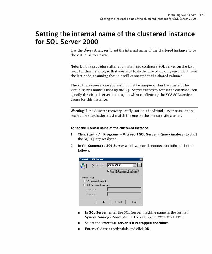
151Installing SQL ServerSetting the internal name of the clustered instance for SQL Server 2000
Setting the internal name of the clustered instance for SQL Server 2000
Use the Query Analyzer to set the internal name of the clustered instance to be the virtual server name.
Note: Do this procedure after you install and configure SQL Server on the last node for this instance, so that you need to do the procedure only once. Do it from the last node, assuming that it is still connected to the shared volumes.
The virtual server name you assign must be unique within the cluster. The virtual server name is used by the SQL Server clients to access the database. You specify the virtual server name again when configuring the VCS SQL service group for this instance.
Warning: For a disaster recovery configuration, the virtual server name on the secondary site cluster must match the one on the primary site cluster.
To set the internal name of the clustered instance
1 Click Start > All Programs > Microsoft SQL Server > Query Analyzer to start the SQL Query Analyzer.
2 In the Connect to SQL Server window, provide connection information as follows:
■ In SQL Server, enter the SQL Server machine name in the format System_Name\Instance_Name. For example SYSTEM2\INST1.
■ Select the Start SQL server if it is stopped checkbox.
■ Enter valid user credentials and click OK.
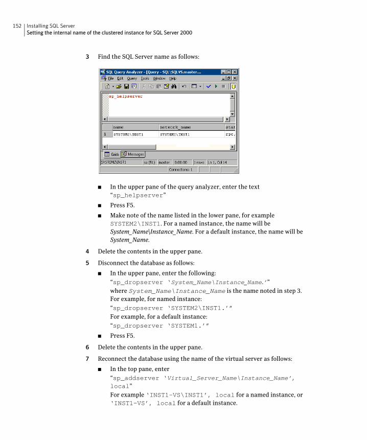
152 Installing SQL ServerSetting the internal name of the clustered instance for SQL Server 2000
3 Find the SQL Server name as follows:
■ In the upper pane of the query analyzer, enter the text “sp_helpserver”
■ Press F5.
■ Make note of the name listed in the lower pane, for example SYSTEM2\INST1. For a named instance, the name will be System_Name\Instance_Name. For a default instance, the name will be System_Name.
4 Delete the contents in the upper pane.
5 Disconnect the database as follows:
■ In the upper pane, enter the following:
“sp_dropserver ‘System_Name\Instance_Name.’”
where System_Name\Instance_Name is the name noted in step 3. For example, for named instance:
“sp_dropserver ‘SYSTEM2\INST1.’”
For example, for a default instance:
“sp_dropserver ‘SYSTEM1.’”
■ Press F5.
6 Delete the contents in the upper pane.
7 Reconnect the database using the name of the virtual server as follows:
■ In the top pane, enter
“sp_addserver ‘Virtual_Server_Name\Instance_Name’, local”
For example ‘INST1-VS\INST1’, local for a named instance, or ‘INST1-VS’, local for a default instance.
153Installing SQL ServerCreating a SQL Server user-defined database
■ Press F5.
Creating a SQL Server user-defined databaseYou can use SFW HA to manage SQL Server user-defined databases. For making the user-defined databases highly available, create the user-defined databases and then configure them in the SQL Server service group. Refer to the Microsoft SQL Server documentation for instructions on how to create databases.
Refer to the following guidelines before creating and configuring the user-defined databases:
■ The user-defined databases must reside on shared disks. If you have not already created volumes for a user-defined SQL Server database and its transaction log, create them first.
See “Creating volumes” on page 120.
■ Create the SQL Server database for the desired SQL server virtual server instance, and point the database files and transaction log to the new volumes created for them.
Refer to the Microsoft SQL Server documentation for instructions.
■ After creating the database, you may have additional steps to complete in the SQL Server configuration. Perform the desired steps depending on your configuration plans.
See “Completing configuration steps in SQL Server” on page 154.
■ If you have already configured the SQL Server service group, run the SQL Server Configuration Wizard again to modify the SQL Server service group. This allows the wizard to add storage agent resources for the new database, to the existing service group.
You must run the SQL Server Configuration Wizard in the modify mode only if you create user-defined databases after creating the SQL Server service group.
See “Modifying a SQL Server service group to add VMDg and MountV resources” on page 173.
154 Installing SQL ServerCompleting configuration steps in SQL Server
Completing configuration steps in SQL ServerDepending on your configuration, you may have additional steps to complete in SQL Server.
If you plan to implement a disaster recovery configuration using Veritas Volume Replicator (VVR), Symantec recommends that you exclude the tempdb database from replication. To do this, you need to first move it to a separate volume within the system database disk group.
See “Moving the tempdb database if using VVR for disaster recovery” on page 154.
If you are running multiple SQL Server instances, you must assign a different port to each SQL Server instance.
See “Assigning ports for multiple SQL Server instances” on page 154.
Moving the tempdb database if using VVR for disaster recoveryIf you plan to implement a disaster recovery configuration using VVR, Symantec recommends that you move tempdb to a separate volume within the system database disk group in order to be able to exclude it from replication.
If you have not yet created the volume for tempdb, you can do that now.
See “Creating volumes” on page 120.
Then, refer to the Microsoft SQL Server documentation for the instructions on moving the tempdb database.
Assigning ports for multiple SQL Server instancesIf you are running multiple SQL Server instances, you must assign a different port to each named instance. You can assign static or dynamic ports. Refer to the Microsoft Knowledge Base for instructions on how to assign ports.
If you wish to change the port after configuring the SQL service group, you must perform the steps in the following order:
■ Bring the SQL service group online or partially online (up to the registry replication resource) on a cluster node.
■ On the node on which the SQL service group is online or partially online, change the port assigned to the SQL instance. Refer to the Microsoft SQL Server documentation for instructions.
■ Take the SQL service group offline on the node, and then bring it online again. The configuration changes will be replicated to the remaining cluster nodes.
Chapter
7Configuring SQL Server for failover
This chapter contains the following topics:
■ About configuring the VCS SQL Server service group
■ Verifying the SQL Server cluster configuration
■ Configuring an MSDTC Server service group
■ About configuring the MSDTC client for SQL Server
■ About the VCS Application Manager utility
■ Viewing DTC transaction information
■ Modifying a SQL Server service group to add VMDg and MountV resources
■ Determining additional steps needed
156 Configuring SQL Server for failoverAbout configuring the VCS SQL Server service group
About configuring the VCS SQL Server service groupA SQL service group is used to bring a SQL Server instance online on another node if the active node fails. If you have set up multiple cluster nodes, you specify the priority of the failover node while configuring the service group.
You use the VCS SQL Server Configuration Wizard to configure the service group.
Read the following topics:
■ Service group requirements for Active-Active configurations
■ Prerequisites for configuring the SQL service group
■ Creating the SQL Server service group
Service group requirements for Active-Active configurationsNote the following requirements for Active-Active configurations:
■ For an Active-Active configuration, you must create a separate service group for each instance.
■ Each service group that you create must have a unique service group name and virtual IP address.
■ For an Active-Active configuration, when you specify the priority order of systems, reverse the order for each service group so that the active system and failover system are opposite for each instance. For example, if you have two instances and two systems, you would set the priority order as follows:
Prerequisites for configuring the SQL service groupNote the following prerequisites before configuring the SQL service group for a high availability cluster, campus cluster, or a Replicated Data Cluster:
■ Verify that you have completed the steps in the high availability, campus cluster, or RDC workflows up through the step of installing SQL Server on all nodes.
See the following topics as appropriate:
INSTANCE 1 Priority order:SYSTEM1SYSTEM2
INSTANCE2 Priority order:SYSTEM2SYSTEM1
157Configuring SQL Server for failoverAbout configuring the VCS SQL Server service group
■ “High availability (HA) configuration (New Server)” on page 35
■ “High availability (HA) configuration (Existing Server)” on page 38
■ “VCS campus cluster configuration” on page 42
■ “VCS Replicated Data Cluster configuration” on page 45
■ Verify that you have VCS Cluster Administrator privileges. This user classification is required to configure service groups.
■ You must be a local Administrator on the node where you run the wizard. If you wish to configure detail monitoring, you must have the permission to log on to the respective SQL instance.
■ Verify that the SQL Server instance is installed identically on all nodes that will participate in the service group.
■ Verify that the drive containing the SQL Server system data files and registry replication information is mounted on the node on which you are configuring the service group.
See “About managing disk groups and volumes” on page 125.
■ Assign a unique virtual IP address for the SQL Server instance. You specify this IP address when configuring the service group.
■ If you wish to use a script for detail monitoring, for example, to create a table and write data to it, note the location(s) of the script to use. Either locate the script file in shared storage or ensure that the same file exists in the same location on all the cluster nodes.
A sample script is supplied in the following directory:
C:\Program Files\Veritas\cluster
server\bin\SQLServer2005\sample_script.sql
■ Make sure that the following services are stopped on the first cluster node where you are running the wizard:
■ SQL Server
■ SQL Server Agent
■ SQL Server Analysis Services
Stop these services for the SQL instances that you wish to configure in the service group.
■ If you have configured a Firewall, add the following to the Firewall Exceptions list:
■ Port 14150 or the VCS Command Server service, %vcs_home%\bin\CmdServer.exe.
Here, %vcs_home% is the installation directory for VCS, typically C:\Program Files\Veritas\Cluster Server.
■ Port 14141
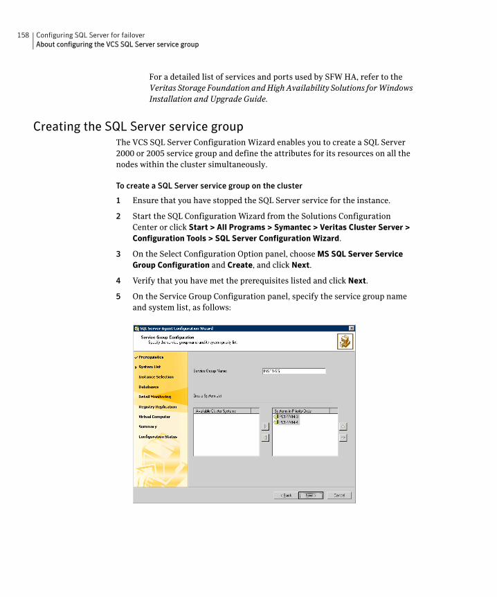
158 Configuring SQL Server for failoverAbout configuring the VCS SQL Server service group
For a detailed list of services and ports used by SFW HA, refer to the Veritas Storage Foundation and High Availability Solutions for Windows Installation and Upgrade Guide.
Creating the SQL Server service groupThe VCS SQL Server Configuration Wizard enables you to create a SQL Server 2000 or 2005 service group and define the attributes for its resources on all the nodes within the cluster simultaneously.
To create a SQL Server service group on the cluster
1 Ensure that you have stopped the SQL Server service for the instance.
2 Start the SQL Configuration Wizard from the Solutions Configuration Center or click Start > All Programs > Symantec > Veritas Cluster Server > Configuration Tools > SQL Server Configuration Wizard.
3 On the Select Configuration Option panel, choose MS SQL Server Service Group Configuration and Create, and click Next.
4 Verify that you have met the prerequisites listed and click Next.
5 On the Service Group Configuration panel, specify the service group name and system list, as follows:
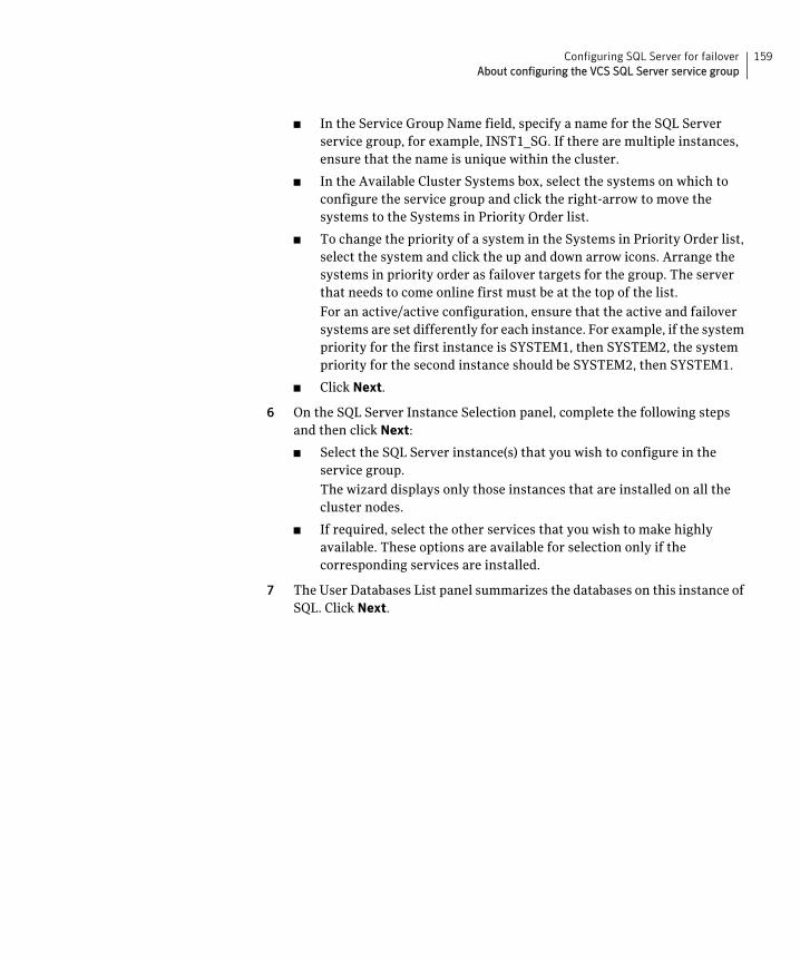
159Configuring SQL Server for failoverAbout configuring the VCS SQL Server service group
■ In the Service Group Name field, specify a name for the SQL Server service group, for example, INST1_SG. If there are multiple instances, ensure that the name is unique within the cluster.
■ In the Available Cluster Systems box, select the systems on which to configure the service group and click the right-arrow to move the systems to the Systems in Priority Order list.
■ To change the priority of a system in the Systems in Priority Order list, select the system and click the up and down arrow icons. Arrange the systems in priority order as failover targets for the group. The server that needs to come online first must be at the top of the list.
For an active/active configuration, ensure that the active and failover systems are set differently for each instance. For example, if the system priority for the first instance is SYSTEM1, then SYSTEM2, the system priority for the second instance should be SYSTEM2, then SYSTEM1.
■ Click Next.
6 On the SQL Server Instance Selection panel, complete the following steps and then click Next:
■ Select the SQL Server instance(s) that you wish to configure in the service group.
The wizard displays only those instances that are installed on all the cluster nodes.
■ If required, select the other services that you wish to make highly available. These options are available for selection only if the corresponding services are installed.
7 The User Databases List panel summarizes the databases on this instance of SQL. Click Next.
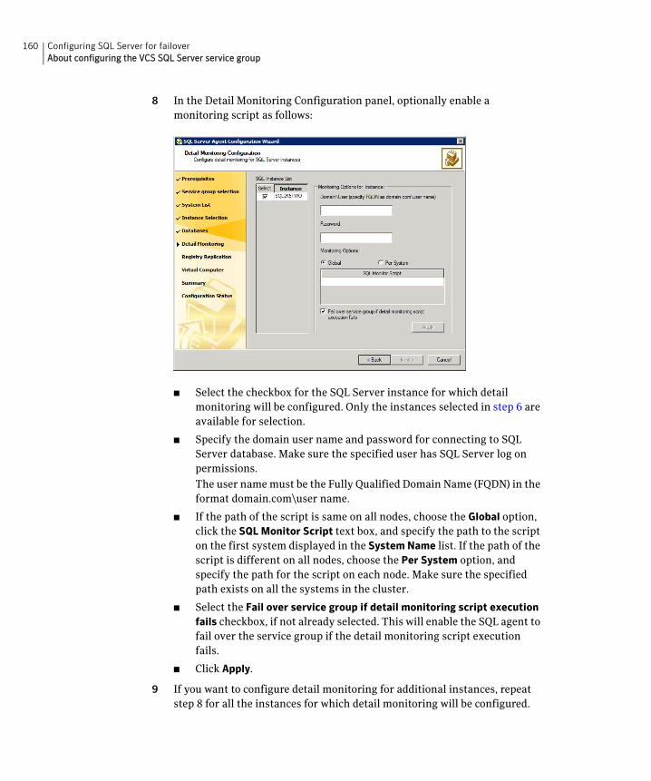
160 Configuring SQL Server for failoverAbout configuring the VCS SQL Server service group
8 In the Detail Monitoring Configuration panel, optionally enable a monitoring script as follows:
■ Select the checkbox for the SQL Server instance for which detail monitoring will be configured. Only the instances selected in step 6 are available for selection.
■ Specify the domain user name and password for connecting to SQL Server database. Make sure the specified user has SQL Server log on permissions.
The user name must be the Fully Qualified Domain Name (FQDN) in the format domain.com\user name.
■ If the path of the script is same on all nodes, choose the Global option, click the SQL Monitor Script text box, and specify the path to the script on the first system displayed in the System Name list. If the path of the script is different on all nodes, choose the Per System option, and specify the path for the script on each node. Make sure the specified path exists on all the systems in the cluster.
■ Select the Fail over service group if detail monitoring script execution fails checkbox, if not already selected. This will enable the SQL agent to fail over the service group if the detail monitoring script execution fails.
■ Click Apply.
9 If you want to configure detail monitoring for additional instances, repeat step 8 for all the instances for which detail monitoring will be configured.
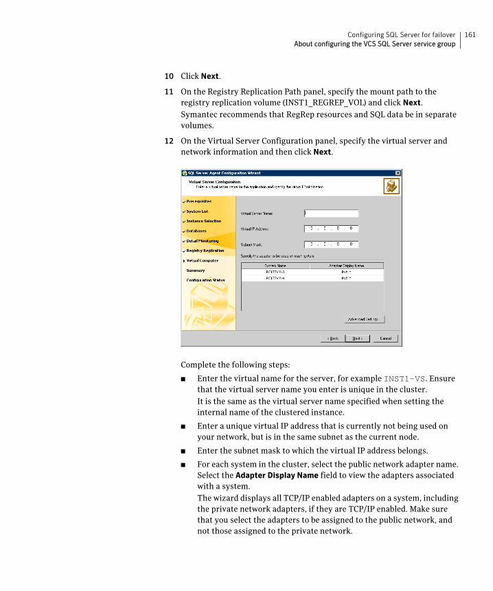
161Configuring SQL Server for failoverAbout configuring the VCS SQL Server service group
10 Click Next.
11 On the Registry Replication Path panel, specify the mount path to the registry replication volume (INST1_REGREP_VOL) and click Next.
Symantec recommends that RegRep resources and SQL data be in separate volumes.
12 On the Virtual Server Configuration panel, specify the virtual server and network information and then click Next.
Complete the following steps:
■ Enter the virtual name for the server, for example INST1-VS. Ensure that the virtual server name you enter is unique in the cluster.
It is the same as the virtual server name specified when setting the internal name of the clustered instance.
■ Enter a unique virtual IP address that is currently not being used on your network, but is in the same subnet as the current node.
■ Enter the subnet mask to which the virtual IP address belongs.
■ For each system in the cluster, select the public network adapter name. Select the Adapter Display Name field to view the adapters associated with a system.
The wizard displays all TCP/IP enabled adapters on a system, including the private network adapters, if they are TCP/IP enabled. Make sure that you select the adapters to be assigned to the public network, and not those assigned to the private network.

162 Configuring SQL Server for failoverAbout configuring the VCS SQL Server service group
■ If you require a computer object to be created in the Active Directory (AD), click Advanced Settings, check the Active Directory Update Required check box, specify the desired Organizational Unit in the domain and then click OK. The user account configured for VCS Helper service must have adequate privileges on the specified container to create and update computer accounts.
This sets the Lanman resource attributes ADUpdateRequired and ADCriticalForOnline to true. This allows the Lanman agent to update Active Directory with the SQL virtual server name.
You can type the OU details in the format CN=Computers,DC=domainname,DC=com.
To search for the OU, click the ellipsis button and specify the search criteria in the Windows Find Organizational Units dialog box.
By default, the Lanman resource adds the virtual server name to the default container "Computers."
13 In the Service Group Summary panel, review the service group configuration and then click Next.
The Resources box lists the configured resources. The wizard assigns unique names to resources based on their respective name rules. Click a resource to view its attributes and their configured values in the Attributes box.
Optionally, if desired, change the names of the resources as follows:
■ To edit a resource name, click the resource name or press the F2 key. Press the Enter key after editing each resource name.
■ To cancel editing a resource name, press the Esc key.
14 Click Yes when prompted to confirm creating the service group. Messages indicate the status of the commands.
15 Complete the SQL Server service group configuration as follows:
■ In the Bring the service group online check box, if you want to bring the service group online later, clear the check box.
You may want to review the service group configuration in the Cluster Manager (Java Console) before bringing the service group online. You can use the Cluster Manager to bring the service group online later.
■ Click Finish to exit the wizard or click Next to configure another SQL service group or an MSDTC service group.
The wizard marks all the resources in the service group as CRITICAL. If desired, use Cluster Manager (Java Console) or the command line to change the state.

163Configuring SQL Server for failoverAbout configuring the VCS SQL Server service group
If you have created a new SQL Server database, you must modify the SQL Server service group to add VMDg and MountV resources to the service group by running the SQL Server Configuration Wizard.
See “Modifying a SQL Server service group to add VMDg and MountV resources” on page 173.
164 Configuring SQL Server for failoverVerifying the SQL Server cluster configuration
Verifying the SQL Server cluster configurationFailover simulation is an important part of configuration testing.
To verify the configuration of a cluster, either move the online groups, or shut down an active cluster node.
■ Use Veritas Cluster Manager (Java Console) to switch all the service groups from one node to another.
■ Simulate a local cluster failover by shutting down an active cluster node.
To switch service groups
1 In the Veritas Cluster Manager (Java Console), click the cluster in the configuration tree, click the Service Groups tab, and right-click the service group icon in the view panel.
■ Click Switch To, and click the appropriate node from the menu.
■ In the dialog box, click Yes. The service group you selected is taken offline on the original node and brought online on the node you selected.
If there is more than one service group, you must repeat this step until all the service groups are switched.
2 Verify that the service group is online on the node you selected to switch to in step 1.
3 To move all the resources back to the original node, repeat step 1 for each of the service groups.
To shut down an active cluster node
1 Gracefully shut down or restart the cluster node where the service group is online.
2 In the Veritas Cluster Manager (Java Console) on another node, connect to the cluster.
3 Verify that the service group has failed over successfully, and is online on the next node in the system list.
4 If you need to move all the service groups back to the original node:
■ Restart the node you shut down in step 1.
■ Click Switch To, and click the appropriate node from the menu.
■ In the dialog box, click Yes.
The service group you selected is taken offline and brought online on the node that you selected.
165Configuring SQL Server for failoverConfiguring an MSDTC Server service group
Configuring an MSDTC Server service groupMSDTC is a global resource and can be accessed by more than one SQL Server service group. Symantec recommends that you configure only one MSDTC service group in a VCS cluster.
To configure high availability for MSDTC Server, you first use the SQL Server Configuration Wizard to create a service group for the MSDTC Server and then configure the MSDTC client manually.
Prerequisites for MSDTC configurationReview the following prerequisites before configuring the MSDTC service group:
■ Verify that the MSDTC service is installed on all nodes that will participate in the MSDTC Server service group.
■ You must be a Cluster Administrator. This user classification is required to create and configure a service group.
■ You must be a local Administrator on the node where you run the wizard.
■ Verify that the VCS Database Agent for SQL Server is installed on all cluster nodes.
■ Verify that the VCS cluster is configured using the VCS Cluster Configuration Wizard (VCW).
■ Verify that the drives for the MSDTC logs and registry replication information are mounted on the node on which you are configuring the service group and unmounted on all other nodes.
■ Verify that the Microsoft Distributed Transaction Coordinator (MSDTC) service is stopped.
■ Keep the following information ready with you; the wizard prompts you for these details:
■ A unique virtual server name for the MSDTC Server. This is the name that is used by MSDTC clients to connect to the MSDTC Server. The DTC service runs under this name.
■ A unique virtual IP address for the MSDTC Server.
Creating an MSDTC Server service groupUse the SQL Server Configuration Wizard to configure a service group for the MSDTC Server. After configuring the service group, proceed to configuring the MSDTC client.
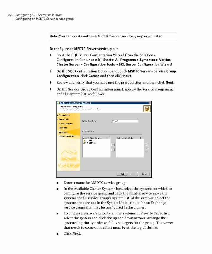
166 Configuring SQL Server for failoverConfiguring an MSDTC Server service group
Note: You can create only one MSDTC Server service group in a cluster.
To configure an MSDTC Server service group
1 Start the SQL Server Configuration Wizard from the Solutions Configuration Center or click Start > All Programs > Symantec > Veritas Cluster Server > Configuration Tools > SQL Server Configuration Wizard.
2 On the SQL Configuration Option panel, click MSDTC Server - Service Group Configuration, click Create and then click Next.
3 Review and verify that you have met the prerequisites and then click Next.
4 On the Service Group Configuration panel, specify the service group name and the system list, as follows:
■ Enter a name for MSDTC service group.
■ In the Available Cluster Systems box, select the systems on which to configure the service group and click the right-arrow to move the systems to the service group’s system list. Make sure you select the systems that are not in the SystemList attribute for an Exchange service group that may be configured in the cluster.
■ To change a system’s priority, in the Systems in Priority Order list, select the system and click the up and down arrows. Arrange the systems in priority order as failover targets for the group. The server that needs to come online first must be at the top of the list.
■ Click Next.
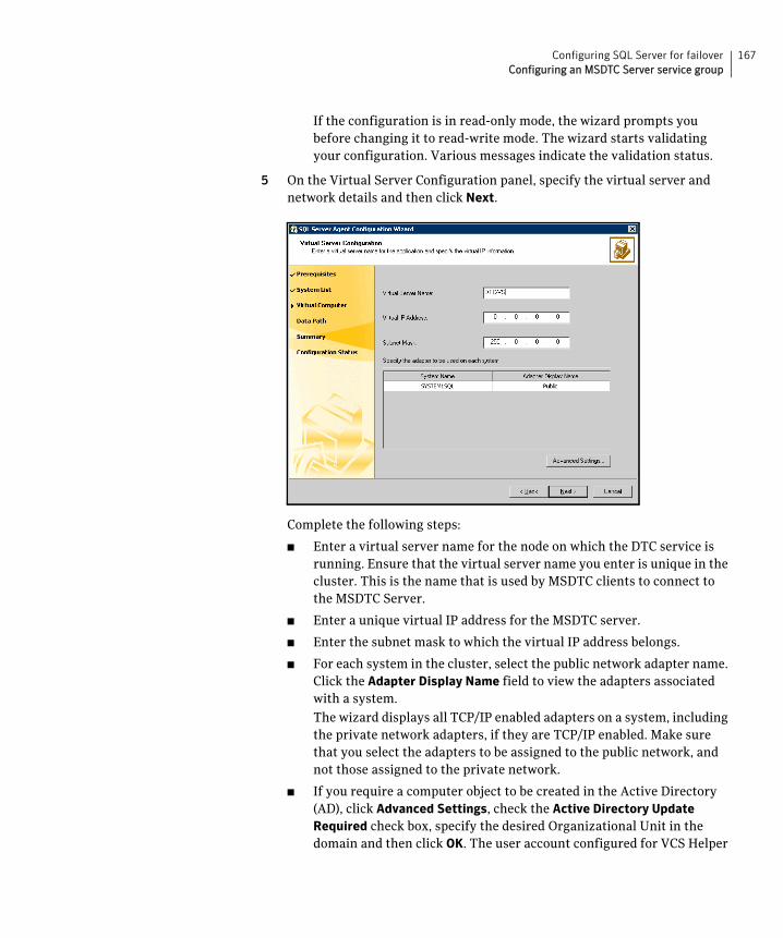
167Configuring SQL Server for failoverConfiguring an MSDTC Server service group
If the configuration is in read-only mode, the wizard prompts you before changing it to read-write mode. The wizard starts validating your configuration. Various messages indicate the validation status.
5 On the Virtual Server Configuration panel, specify the virtual server and network details and then click Next.
Complete the following steps:
■ Enter a virtual server name for the node on which the DTC service is running. Ensure that the virtual server name you enter is unique in the cluster. This is the name that is used by MSDTC clients to connect to the MSDTC Server.
■ Enter a unique virtual IP address for the MSDTC server.
■ Enter the subnet mask to which the virtual IP address belongs.
■ For each system in the cluster, select the public network adapter name. Click the Adapter Display Name field to view the adapters associated with a system.
The wizard displays all TCP/IP enabled adapters on a system, including the private network adapters, if they are TCP/IP enabled. Make sure that you select the adapters to be assigned to the public network, and not those assigned to the private network.
■ If you require a computer object to be created in the Active Directory (AD), click Advanced Settings, check the Active Directory Update Required check box, specify the desired Organizational Unit in the domain and then click OK. The user account configured for VCS Helper
168 Configuring SQL Server for failoverConfiguring an MSDTC Server service group
service must have adequate privileges on the specified container to create and update computer accounts.
This sets the Lanman resource attributes ADUpdateRequired and ADCriticalForOnline to true. This allows the Lanman agent to update Active Directory with the SQL virtual server name.
You can type the OU details in the format CN=Computers,DC=domainname,DC=com.
To search for the OU, click the ellipsis button and specify the search criteria in the Windows Find Organizational Units dialog box.
By default, the Lanman resource adds the virtual server name to the default container "Computers."
6 On the Specify Data Path panel, specify the volumes for the MSDTC log and the replication directory and then click Next.
Symantec recommends using different paths for these directories. If the directory does not exist, the wizard creates it.
7 On the Service Group Summary panel, review the service group configuration and change the resource names if desired, as follows:
■ The Resources box lists the configured resources. Click on a resource to view its attributes and their configured values in the Attributes box.
■ The wizard assigns unique names to resources. Change names of the resources, if desired. To edit a resource name, select the resource name and either click it or press the F2 key. Press Enter after editing each resource name. To cancel editing a resource name, press the Esc key.
■ Click Next.
8 Click Yes on the message that prompts you that the wizard will run commands to modify the service group configuration.
Various messages indicate the status of these commands.
9 In the Configuration Complete panel, check Bring the service group online to bring the configured service group online and then click Finish to exit the wizard.
To bring the service group online later, uncheck the option.
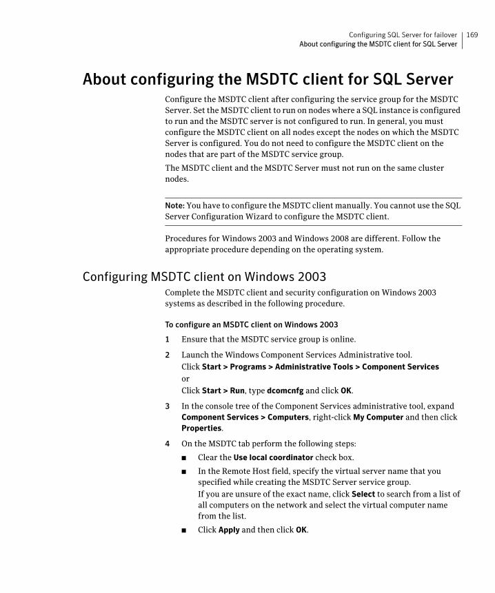
169Configuring SQL Server for failoverAbout configuring the MSDTC client for SQL Server
About configuring the MSDTC client for SQL ServerConfigure the MSDTC client after configuring the service group for the MSDTC Server. Set the MSDTC client to run on nodes where a SQL instance is configured to run and the MSDTC server is not configured to run. In general, you must configure the MSDTC client on all nodes except the nodes on which the MSDTC Server is configured. You do not need to configure the MSDTC client on the nodes that are part of the MSDTC service group.
The MSDTC client and the MSDTC Server must not run on the same cluster nodes.
Note: You have to configure the MSDTC client manually. You cannot use the SQL Server Configuration Wizard to configure the MSDTC client.
Procedures for Windows 2003 and Windows 2008 are different. Follow the appropriate procedure depending on the operating system.
Configuring MSDTC client on Windows 2003Complete the MSDTC client and security configuration on Windows 2003 systems as described in the following procedure.
To configure an MSDTC client on Windows 2003
1 Ensure that the MSDTC service group is online.
2 Launch the Windows Component Services Administrative tool.
Click Start > Programs > Administrative Tools > Component Services
or
Click Start > Run, type dcomcnfg and click OK.
3 In the console tree of the Component Services administrative tool, expand Component Services > Computers, right-click My Computer and then click Properties.
4 On the MSDTC tab perform the following steps:
■ Clear the Use local coordinator check box.
■ In the Remote Host field, specify the virtual server name that you specified while creating the MSDTC Server service group.
If you are unsure of the exact name, click Select to search from a list of all computers on the network and select the virtual computer name from the list.
■ Click Apply and then click OK.
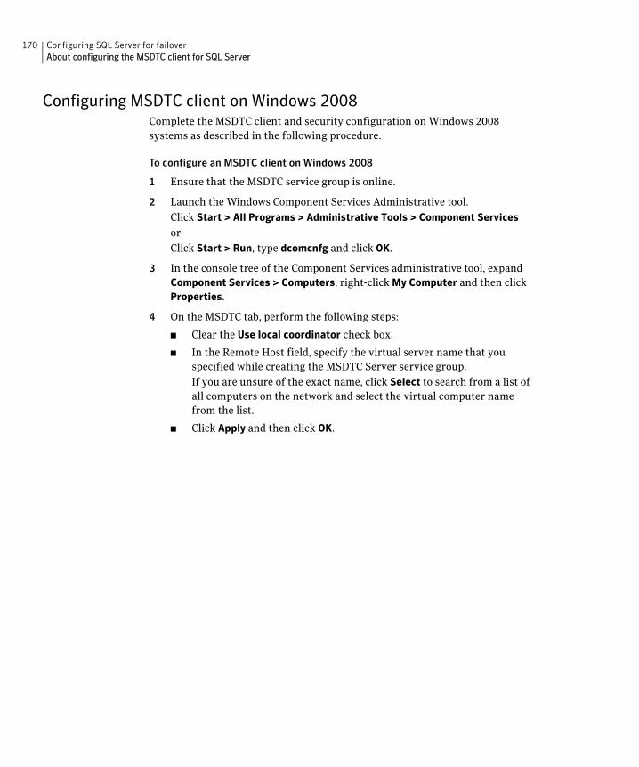
170 Configuring SQL Server for failoverAbout configuring the MSDTC client for SQL Server
Configuring MSDTC client on Windows 2008Complete the MSDTC client and security configuration on Windows 2008 systems as described in the following procedure.
To configure an MSDTC client on Windows 2008
1 Ensure that the MSDTC service group is online.
2 Launch the Windows Component Services Administrative tool.
Click Start > All Programs > Administrative Tools > Component Services
or
Click Start > Run, type dcomcnfg and click OK.
3 In the console tree of the Component Services administrative tool, expand Component Services > Computers, right-click My Computer and then click Properties.
4 On the MSDTC tab, perform the following steps:
■ Clear the Use local coordinator check box.
■ In the Remote Host field, specify the virtual server name that you specified while creating the MSDTC Server service group.
If you are unsure of the exact name, click Select to search from a list of all computers on the network and select the virtual computer name from the list.
■ Click Apply and then click OK.
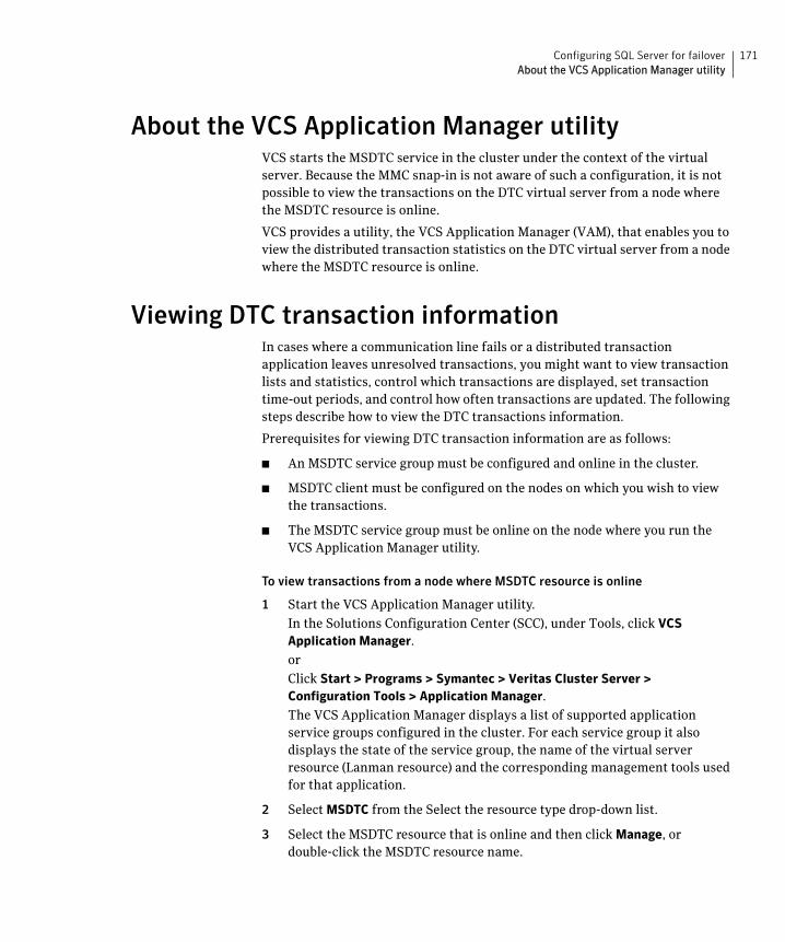
171Configuring SQL Server for failoverAbout the VCS Application Manager utility
About the VCS Application Manager utilityVCS starts the MSDTC service in the cluster under the context of the virtual server. Because the MMC snap-in is not aware of such a configuration, it is not possible to view the transactions on the DTC virtual server from a node where the MSDTC resource is online.
VCS provides a utility, the VCS Application Manager (VAM), that enables you to view the distributed transaction statistics on the DTC virtual server from a node where the MSDTC resource is online.
Viewing DTC transaction informationIn cases where a communication line fails or a distributed transaction application leaves unresolved transactions, you might want to view transaction lists and statistics, control which transactions are displayed, set transaction time-out periods, and control how often transactions are updated. The following steps describe how to view the DTC transactions information.
Prerequisites for viewing DTC transaction information are as follows:
■ An MSDTC service group must be configured and online in the cluster.
■ MSDTC client must be configured on the nodes on which you wish to view the transactions.
■ The MSDTC service group must be online on the node where you run the VCS Application Manager utility.
To view transactions from a node where MSDTC resource is online
1 Start the VCS Application Manager utility.
In the Solutions Configuration Center (SCC), under Tools, click VCS Application Manager.
or
Click Start > Programs > Symantec > Veritas Cluster Server > Configuration Tools > Application Manager.
The VCS Application Manager displays a list of supported application service groups configured in the cluster. For each service group it also displays the state of the service group, the name of the virtual server resource (Lanman resource) and the corresponding management tools used for that application.
2 Select MSDTC from the Select the resource type drop-down list.
3 Select the MSDTC resource that is online and then click Manage, or double-click the MSDTC resource name.
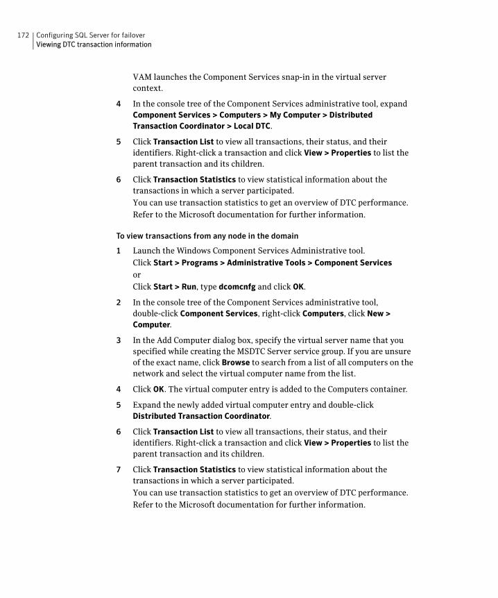
172 Configuring SQL Server for failoverViewing DTC transaction information
VAM launches the Component Services snap-in in the virtual server context.
4 In the console tree of the Component Services administrative tool, expand Component Services > Computers > My Computer > Distributed Transaction Coordinator > Local DTC.
5 Click Transaction List to view all transactions, their status, and their identifiers. Right-click a transaction and click View > Properties to list the parent transaction and its children.
6 Click Transaction Statistics to view statistical information about the transactions in which a server participated.
You can use transaction statistics to get an overview of DTC performance.
Refer to the Microsoft documentation for further information.
To view transactions from any node in the domain
1 Launch the Windows Component Services Administrative tool.
Click Start > Programs > Administrative Tools > Component Services
or
Click Start > Run, type dcomcnfg and click OK.
2 In the console tree of the Component Services administrative tool, double-click Component Services, right-click Computers, click New > Computer.
3 In the Add Computer dialog box, specify the virtual server name that you specified while creating the MSDTC Server service group. If you are unsure of the exact name, click Browse to search from a list of all computers on the network and select the virtual computer name from the list.
4 Click OK. The virtual computer entry is added to the Computers container.
5 Expand the newly added virtual computer entry and double-click Distributed Transaction Coordinator.
6 Click Transaction List to view all transactions, their status, and their identifiers. Right-click a transaction and click View > Properties to list the parent transaction and its children.
7 Click Transaction Statistics to view statistical information about the transactions in which a server participated.
You can use transaction statistics to get an overview of DTC performance.
Refer to the Microsoft documentation for further information.
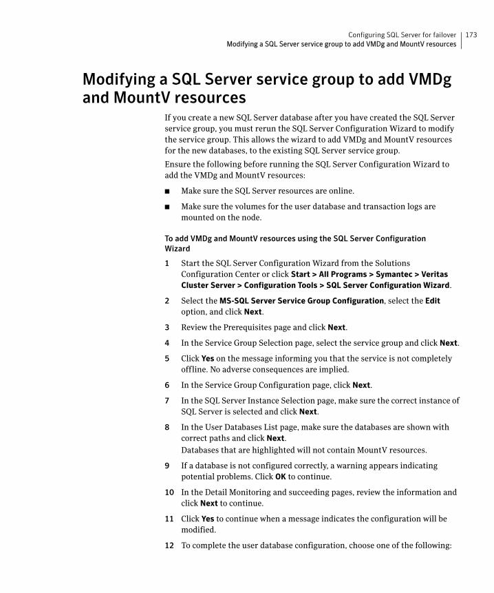
173Configuring SQL Server for failoverModifying a SQL Server service group to add VMDg and MountV resources
Modifying a SQL Server service group to add VMDg and MountV resources
If you create a new SQL Server database after you have created the SQL Server service group, you must rerun the SQL Server Configuration Wizard to modify the service group. This allows the wizard to add VMDg and MountV resources for the new databases, to the existing SQL Server service group.
Ensure the following before running the SQL Server Configuration Wizard to add the VMDg and MountV resources:
■ Make sure the SQL Server resources are online.
■ Make sure the volumes for the user database and transaction logs are mounted on the node.
To add VMDg and MountV resources using the SQL Server Configuration Wizard
1 Start the SQL Server Configuration Wizard from the Solutions Configuration Center or click Start > All Programs > Symantec > Veritas Cluster Server > Configuration Tools > SQL Server Configuration Wizard.
2 Select the MS-SQL Server Service Group Configuration, select the Edit option, and click Next.
3 Review the Prerequisites page and click Next.
4 In the Service Group Selection page, select the service group and click Next.
5 Click Yes on the message informing you that the service is not completely offline. No adverse consequences are implied.
6 In the Service Group Configuration page, click Next.
7 In the SQL Server Instance Selection page, make sure the correct instance of SQL Server is selected and click Next.
8 In the User Databases List page, make sure the databases are shown with correct paths and click Next.
Databases that are highlighted will not contain MountV resources.
9 If a database is not configured correctly, a warning appears indicating potential problems. Click OK to continue.
10 In the Detail Monitoring and succeeding pages, review the information and click Next to continue.
11 Click Yes to continue when a message indicates the configuration will be modified.
12 To complete the user database configuration, choose one of the following:
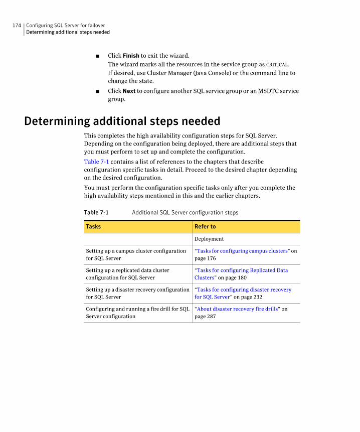
174 Configuring SQL Server for failoverDetermining additional steps needed
■ Click Finish to exit the wizard.
The wizard marks all the resources in the service group as CRITICAL.
If desired, use Cluster Manager (Java Console) or the command line to change the state.
■ Click Next to configure another SQL service group or an MSDTC service group.
Determining additional steps neededThis completes the high availability configuration steps for SQL Server. Depending on the configuration being deployed, there are additional steps that you must perform to set up and complete the configuration.
Table 7-1 contains a list of references to the chapters that describe configuration specific tasks in detail. Proceed to the desired chapter depending on the desired configuration.
You must perform the configuration specific tasks only after you complete the high availability steps mentioned in this and the earlier chapters.
Table 7-1 Additional SQL Server configuration steps
Tasks Refer to
Deployment
Setting up a campus cluster configuration for SQL Server
“Tasks for configuring campus clusters” on page 176
Setting up a replicated data cluster configuration for SQL Server
“Tasks for configuring Replicated Data Clusters” on page 180
Setting up a disaster recovery configuration for SQL Server
“Tasks for configuring disaster recovery for SQL Server” on page 232
Configuring and running a fire drill for SQL Server configuration
“About disaster recovery fire drills” on page 287
Chapter
8Configuring campus clusters for SQL Server
This chapter contains the following topics:
■ Tasks for configuring campus clusters
■ Modifying the IP resource in the SQL Server service group
■ Verifying the campus cluster: Switching the service group
■ Setting the ForceImport attribute to 1 after a site failure
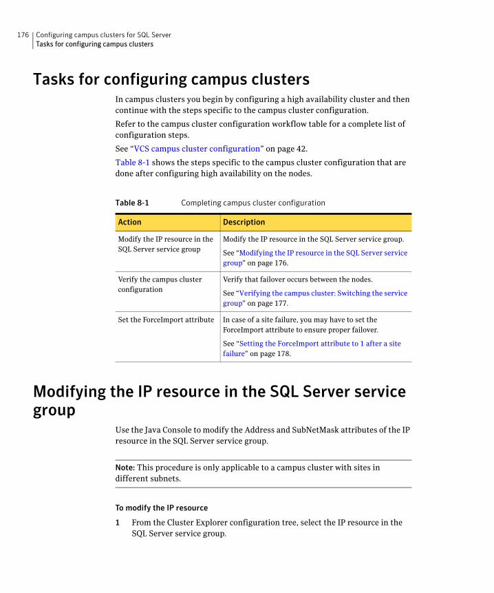
176 Configuring campus clusters for SQL ServerTasks for configuring campus clusters
Tasks for configuring campus clustersIn campus clusters you begin by configuring a high availability cluster and then continue with the steps specific to the campus cluster configuration.
Refer to the campus cluster configuration workflow table for a complete list of configuration steps.
See “VCS campus cluster configuration” on page 42.
Table 8-1 shows the steps specific to the campus cluster configuration that are done after configuring high availability on the nodes.
Modifying the IP resource in the SQL Server service group
Use the Java Console to modify the Address and SubNetMask attributes of the IP resource in the SQL Server service group.
Note: This procedure is only applicable to a campus cluster with sites in different subnets.
To modify the IP resource
1 From the Cluster Explorer configuration tree, select the IP resource in the SQL Server service group.
Table 8-1 Completing campus cluster configuration
Action Description
Modify the IP resource in the SQL Server service group
Modify the IP resource in the SQL Server service group.
See “Modifying the IP resource in the SQL Server service group” on page 176.
Verify the campus cluster configuration
Verify that failover occurs between the nodes.
See “Verifying the campus cluster: Switching the service group” on page 177.
Set the ForceImport attribute In case of a site failure, you may have to set the ForceImport attribute to ensure proper failover.
See “Setting the ForceImport attribute to 1 after a site failure” on page 178.
177Configuring campus clusters for SQL ServerVerifying the campus cluster: Switching the service group
2 In the Properties View, click the Edit icon for the Address attribute.
3 In the Edit Attribute dialog box, make the following selections:
■ Select the Per System option.
■ Select the system at Site B.
■ Enter the virtual IP address at Site B.
■ Click OK.
4 In the Properties View, click the Edit icon for the SubNetMask attribute.
5 In the Edit Attribute dialog box, make the following selections:
■ Select the Per System option.
■ Select the system at Site B.
■ Enter the subnet mask at Site B.
■ Click OK.
6 From the File menu of Cluster Explorer, click Close Configuration.
Verifying the campus cluster: Switching the service group
Failover simulation is an important part of configuration testing.
To verify the campus cluster is functioning properly
1 Bring the service group online on one node as follows:
■ In the Cluster Explorer configuration tree, right-click the service group.
■ Click Online, and click the appropriate system from the menu.
2 Switch the service group to the other node as follows:
■ In the Cluster Explorer configuration tree, right-click the service group.
■ Click Switch To, and click the appropriate system from the menu.
178 Configuring campus clusters for SQL ServerSetting the ForceImport attribute to 1 after a site failure
Setting the ForceImport attribute to 1 after a site failure
ForceImport is a flag that defines whether the agent forcibly imports the disk group when exactly half the disks are available. The value 1 indicates the agent imports the configured disk group when half the disks are available. The value 0 indicates it does not. Default is 0. This means that the disk group will be imported only when SFW acquires control over the majority of the disks.
Warning: Set this attribute to 1 only after verifying the integrity of your data. If due caution is not exercised before setting this attribute to 1, you risk potential data loss.
You must set the ForceImport attribute for the VMDg resource to 1 after a site failure to ensure proper failover.
To set the ForceImport attribute to 1 from the Java Console
1 From the Cluster Explorer configuration tree, select the VMDg resource in the SQL Server service group.
2 In the Properties View, click the Edit icon for the ForceImport attribute.
3 In the Edit Attribute dialog box, make the following selections:
■ Select the Per System option.
■ Select the system in Site B.
■ Select the ForceImport check box.
■ Click OK.
4 From the File menu of Cluster Explorer, click Close Configuration.
5 After the failover takes place, revert the ForceImport attribute to its original value.
To set the ForceImport attribute to 1 from the command line
◆ Use the following command for implementing the force import setting in VCS:
hares -modify <vmdg_resource_name> ForceImport 1|0
Example:
hares -modify vmdg_Dg1 ForceImport 1
Import is forced on vmdg_Dg1.
Chapter
9Configuring Replicated Data Clusters for SQL Server
This chapter contains the following topics:
■ Tasks for configuring Replicated Data Clusters
■ Creating the primary system zone
■ Creating a parallel environment in the secondary zone
■ Adding the systems in the secondary zone to the cluster
■ Setting up security for VVR
■ Setting up the Replicated Data Sets (RDS)
■ Configuring a hybrid RVG service group for replication
■ Setting a dependency between the service groups
■ Adding the nodes from the secondary zone to the RDC
■ Verifying the RDC configuration
■ Additional instructions for GCO disaster recovery
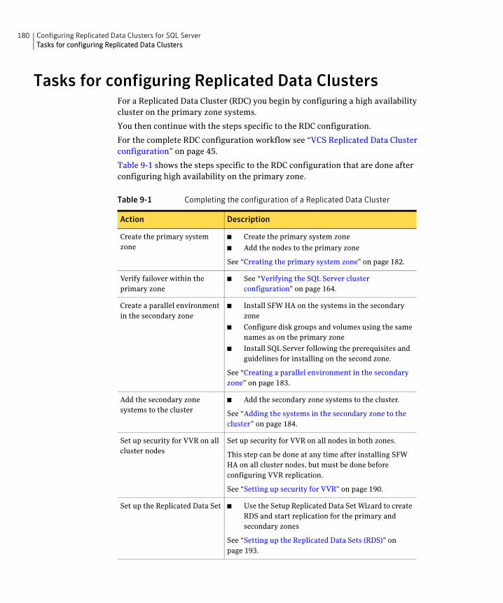
180 Configuring Replicated Data Clusters for SQL ServerTasks for configuring Replicated Data Clusters
Tasks for configuring Replicated Data ClustersFor a Replicated Data Cluster (RDC) you begin by configuring a high availability cluster on the primary zone systems.
You then continue with the steps specific to the RDC configuration.
For the complete RDC configuration workflow see “VCS Replicated Data Cluster configuration” on page 45.
Table 9-1 shows the steps specific to the RDC configuration that are done after configuring high availability on the primary zone.
Table 9-1 Completing the configuration of a Replicated Data Cluster
Action Description
Create the primary system zone
■ Create the primary system zone
■ Add the nodes to the primary zone
See “Creating the primary system zone” on page 182.
Verify failover within the primary zone
■ See “Verifying the SQL Server cluster configuration” on page 164.
Create a parallel environment in the secondary zone
■ Install SFW HA on the systems in the secondary zone
■ Configure disk groups and volumes using the same names as on the primary zone
■ Install SQL Server following the prerequisites and guidelines for installing on the second zone.
See “Creating a parallel environment in the secondary zone” on page 183.
Add the secondary zone systems to the cluster
■ Add the secondary zone systems to the cluster.
See “Adding the systems in the secondary zone to the cluster” on page 184.
Set up security for VVR on all cluster nodes
Set up security for VVR on all nodes in both zones.
This step can be done at any time after installing SFW HA on all cluster nodes, but must be done before configuring VVR replication.
See “Setting up security for VVR” on page 190.
Set up the Replicated Data Set ■ Use the Setup Replicated Data Set Wizard to create RDS and start replication for the primary and secondary zones
See “Setting up the Replicated Data Sets (RDS)” on page 193.
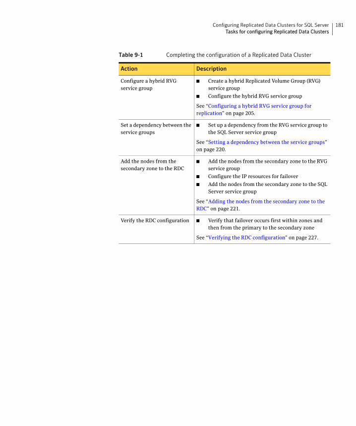
181Configuring Replicated Data Clusters for SQL ServerTasks for configuring Replicated Data Clusters
Configure a hybrid RVG service group
■ Create a hybrid Replicated Volume Group (RVG) service group
■ Configure the hybrid RVG service group
See “Configuring a hybrid RVG service group for replication” on page 205.
Set a dependency between the service groups
■ Set up a dependency from the RVG service group to the SQL Server service group
See “Setting a dependency between the service groups” on page 220.
Add the nodes from the secondary zone to the RDC
■ Add the nodes from the secondary zone to the RVG service group
■ Configure the IP resources for failover
■ Add the nodes from the secondary zone to the SQL Server service group
See “Adding the nodes from the secondary zone to the RDC” on page 221.
Verify the RDC configuration ■ Verify that failover occurs first within zones and then from the primary to the secondary zone
See “Verifying the RDC configuration” on page 227.
Table 9-1 Completing the configuration of a Replicated Data Cluster
Action Description
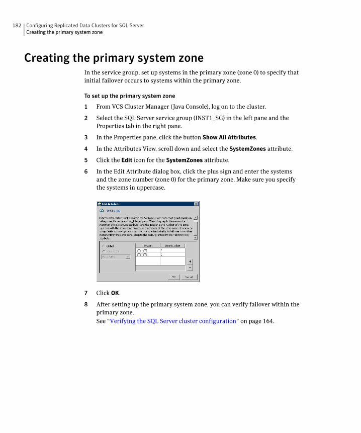
182 Configuring Replicated Data Clusters for SQL ServerCreating the primary system zone
Creating the primary system zoneIn the service group, set up systems in the primary zone (zone 0) to specify that initial failover occurs to systems within the primary zone.
To set up the primary system zone
1 From VCS Cluster Manager (Java Console), log on to the cluster.
2 Select the SQL Server service group (INST1_SG) in the left pane and the Properties tab in the right pane.
3 In the Properties pane, click the button Show All Attributes.
4 In the Attributes View, scroll down and select the SystemZones attribute.
5 Click the Edit icon for the SystemZones attribute.
6 In the Edit Attribute dialog box, click the plus sign and enter the systems and the zone number (zone 0) for the primary zone. Make sure you specify the systems in uppercase.
7 Click OK.
8 After setting up the primary system zone, you can verify failover within the primary zone.
See “Verifying the SQL Server cluster configuration” on page 164.
183Configuring Replicated Data Clusters for SQL ServerCreating a parallel environment in the secondary zone
Creating a parallel environment in the secondary zone
After setting up a SFW HA environment in the primary zone, you set up a parallel environment in the secondary zone.
Before you begin to configure the secondary zone, do the following:
■ Offline the following resources in the SQL service group in the primary zone:
■ SQL Server resource (<sqlservicegroupname> - SQLServer2005 or <sqlservicegroupname> - SQLServer2000)
■ SQL Virtual Server name resource (<sqlservicegroupname> - Lanman)
■ SQL Virtual IP resource (<sqlservicegroupname> - IP)
The remaining resources should be online, including the VMDg resources and the MountV resources.
■ In VEA, make sure to remove all the drive letters from the configured volumes, to avoid conflicts when configuring the zones.
Then complete the following tasks to configure the secondary zone, using the guidelines shown:
■ “Configuring the storage hardware and network” on page 104
■ “Installing Veritas Storage Foundation HA for Windows” on page 106
■ “Configuring cluster disk groups and volumes for SQL Server” on page 112
During the creation of disk groups and volumes for the secondary zone, make sure the following is exactly the same as the cluster at the primary zone:
■ Cluster disk group name
■ Volume sizes
■ Volume names
■ Drive letters
■ Installing and configuring SQL Server on the first cluster node
Choose the appropriate topic from the following:
■ “Installing and configuring SQL Server 2000 on the first cluster node” on page 144
■ “Installing and configuring SQL Server 2005 on the first cluster node” on page 147
When installing SQL Server make sure that you select the same installation options as you did for the primary zone. The instance name must be the same in the primary zone and secondary zone
184 Configuring Replicated Data Clusters for SQL ServerAdding the systems in the secondary zone to the cluster
■ “Installing SQL Server on the second cluster node” on page 149
After you install SQL Server on the nodes in the secondary zone, make sure to use VEA to remove all the drive letters from the configured volumes.
You do not create another cluster in the secondary zone. Instead you add the systems to the existing cluster.
See “Adding the systems in the secondary zone to the cluster” on page 184.
You do not create another SQL service group in the secondary zone. You continue with the remaining VVR configuration tasks, during which the secondary zone nodes will be added to the SQL service group.
For the complete RDC workflow, see“VCS Replicated Data Cluster configuration” on page 45.
Adding the systems in the secondary zone to the cluster
Add the nodes in the secondary zone to the existing cluster with the following procedure.
To add a node to a VCS cluster
1 Start the VCS Cluster Configuration wizard.
Click Start > All Programs > Symantec > Veritas Cluster Server > Configuration Tools > Cluster Configuration Wizard.
Run the wizard from the node to be added or from a node in the cluster. The node that is being added should be part of the domain to which the cluster belongs.
2 Read the information on the Welcome panel and click Next.
3 On the Configuration Options panel, click Cluster Operations and click Next.
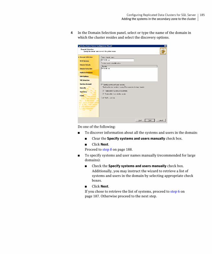
185Configuring Replicated Data Clusters for SQL ServerAdding the systems in the secondary zone to the cluster
4 In the Domain Selection panel, select or type the name of the domain in which the cluster resides and select the discovery options.
Do one of the following:
■ To discover information about all the systems and users in the domain:
■ Clear the Specify systems and users manually check box.
■ Click Next.
Proceed to step 8 on page 188.
■ To specify systems and user names manually (recommended for large domains):
■ Check the Specify systems and users manually check box.
Additionally, you may instruct the wizard to retrieve a list of systems and users in the domain by selecting appropriate check boxes.
■ Click Next.
If you chose to retrieve the list of systems, proceed to step 6 on page 187. Otherwise proceed to the next step.
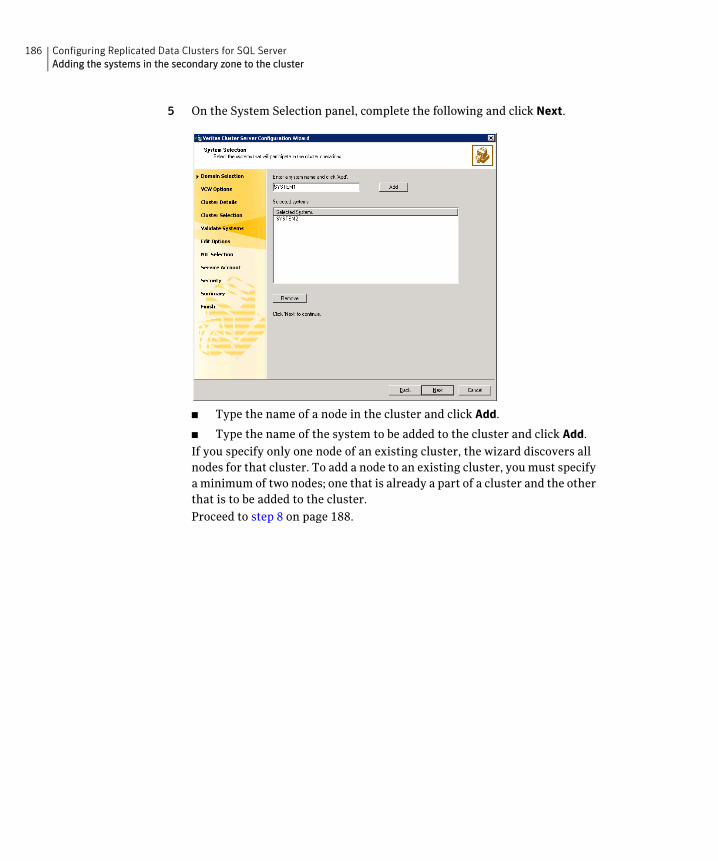
186 Configuring Replicated Data Clusters for SQL ServerAdding the systems in the secondary zone to the cluster
5 On the System Selection panel, complete the following and click Next.
■ Type the name of a node in the cluster and click Add.
■ Type the name of the system to be added to the cluster and click Add.
If you specify only one node of an existing cluster, the wizard discovers all nodes for that cluster. To add a node to an existing cluster, you must specify a minimum of two nodes; one that is already a part of a cluster and the other that is to be added to the cluster.
Proceed to step 8 on page 188.
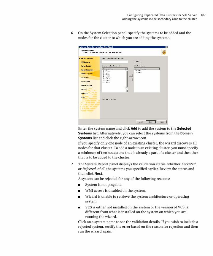
187Configuring Replicated Data Clusters for SQL ServerAdding the systems in the secondary zone to the cluster
6 On the System Selection panel, specify the systems to be added and the nodes for the cluster to which you are adding the systems.
Enter the system name and click Add to add the system to the Selected Systems list. Alternatively, you can select the systems from the Domain Systems list and click the right-arrow icon.
If you specify only one node of an existing cluster, the wizard discovers all nodes for that cluster. To add a node to an existing cluster, you must specify a minimum of two nodes; one that is already a part of a cluster and the other that is to be added to the cluster.
7 The System Report panel displays the validation status, whether Accepted or Rejected, of all the systems you specified earlier. Review the status and then click Next.
A system can be rejected for any of the following reasons:
■ System is not pingable.
■ WMI access is disabled on the system.
■ Wizard is unable to retrieve the system architecture or operating system.
■ VCS is either not installed on the system or the version of VCS is different from what is installed on the system on which you are running the wizard.
Click on a system name to see the validation details. If you wish to include a rejected system, rectify the error based on the reason for rejection and then run the wizard again.
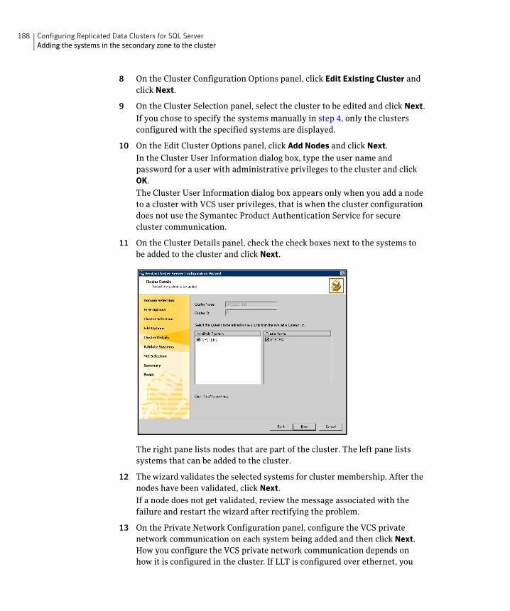
188 Configuring Replicated Data Clusters for SQL ServerAdding the systems in the secondary zone to the cluster
8 On the Cluster Configuration Options panel, click Edit Existing Cluster and click Next.
9 On the Cluster Selection panel, select the cluster to be edited and click Next.
If you chose to specify the systems manually in step 4, only the clusters configured with the specified systems are displayed.
10 On the Edit Cluster Options panel, click Add Nodes and click Next.
In the Cluster User Information dialog box, type the user name and password for a user with administrative privileges to the cluster and click OK.
The Cluster User Information dialog box appears only when you add a node to a cluster with VCS user privileges, that is when the cluster configuration does not use the Symantec Product Authentication Service for secure cluster communication.
11 On the Cluster Details panel, check the check boxes next to the systems to be added to the cluster and click Next.
The right pane lists nodes that are part of the cluster. The left pane lists systems that can be added to the cluster.
12 The wizard validates the selected systems for cluster membership. After the nodes have been validated, click Next.
If a node does not get validated, review the message associated with the failure and restart the wizard after rectifying the problem.
13 On the Private Network Configuration panel, configure the VCS private network communication on each system being added and then click Next. How you configure the VCS private network communication depends on how it is configured in the cluster. If LLT is configured over ethernet, you
189Configuring Replicated Data Clusters for SQL ServerAdding the systems in the secondary zone to the cluster
have to use the same on the nodes being added. Similarly, if LLT is configured over UDP in the cluster, you have to use the same on the nodes being added.
Do one of the following:
■ To configure the VCS private network over ethernet, complete the following steps:
■ Select the check boxes next to the two NICs to be assigned to the private network.
Symantec recommends reserving two NICs exclusively for the private network. However, you could lower the priority of one NIC and use the low-priority NIC for both public and private communication.
■ If you have only two NICs on a selected system, it is recommended that you lower the priority of at least one NIC that will be used for private as well as public network communication.
To lower the priority of a NIC, right-click the NIC and select Low Priority from the pop-up menu.
■ If your configuration contains teamed NICs, the wizard groups them as "NIC Group #N" where "N" is a number assigned to the teamed NIC. A teamed NIC is a logical NIC, formed by grouping several physical NICs together. All NICs in a team have an identical MAC address. Symantec recommends that you do not select teamed NICs for the private network.
The wizard will configure the LLT service (over ethernet) on the selected network adapters.
■ To configure the VCS private network over the User Datagram Protocol (UDP) layer, complete the following steps:
■ Select Configure LLT over UDP.
■ Select the check boxes next to the two NICs to be assigned to the private network. You can assign maximum eight network links.
Symantec recommends reserving at least two NICs exclusively for the VCS private network.
■ Specify a unique UDP port for each of the link. Click Edit Ports if you wish to edit the UDP ports for the links. You can use ports in the range 49152 to 65535. The default ports numbers are 50000 and 50001 respectively. Click OK.
■ For each selected NIC, verify the displayed IP address. If a selected NIC has multiple IP addresses assigned, double-click the field and choose the desired IP address from the drop-down list. Each IP address can be in a different subnet.
190 Configuring Replicated Data Clusters for SQL ServerSetting up security for VVR
The IP address is used for the VCS private communication over the specified UDP port.
■ For each selected NIC, double-click the respective field in the Link column and choose a link from the drop-down list. Specify a different link (Link1 or Link2) for each NIC. Each link is associated with a UDP port that you specified earlier.
The wizard will configure the LLT service (over UDP) on the selected network adapters. The specified UDP ports will be used for the private network communication.
14 On the Public Network Communication panel, select a NIC for public network communication, for each system that is being added, and then click Next.
This step is applicable only if you have configured the ClusterService service group, and the system being added has multiple adapters. If the system has only one adapter for public network communication, the wizard configures that adapter automatically.
15 Specify the password for the user in whose context the VCS Helper service runs.
16 Review the summary information and click Add.
17 The wizard starts running commands to add the node. After all commands have been successfully run, click Finish.
Setting up security for VVRIf you are using Veritas Volume Replicator (VVR) replication, you must configure the VxSAS service on all cluster nodes. For a Replicated Data Cluster environment, you configure the service on all nodes in both the primary and secondary zones.
Configuring the VxSAS serviceComplete the following procedure to configure the VxSAS service for VVR.
The procedure has these prerequisites:
■ You must be logged on with administrative privileges on the server for the wizard to be launched.
■ The account you specify must have administrative and log-on as service privileges on all the specified hosts.
191Configuring Replicated Data Clusters for SQL ServerSetting up security for VVR
■ Avoid specifying blank passwords. In a Windows Server environment, accounts with blank passwords are not supported for log-on service privileges.
■ Make sure that the hosts on which you want to configure the VxSAS service are accessible from the local host.
Note: The VxSAS wizard will not be launched automatically after installing SFW or SFW HA. You must launch this wizard manually to complete the VVR security service configuration. For details on this required service, see Veritas Storage Foundation Veritas Volume Replicator Administrator’s Guide.
To configure the VxSAS service
1 Launch the VVR Security Service Configuration Wizard.
Click Start > All Programs > Symantec > Veritas Storage Foundation > Configuration Wizards > VVR Security Service Configuration Wizard.
or
Type vxsascfg.exe at the command prompt.
2 Read the information provided on the Welcome page and click Next.
3 Complete the Account Information panel as follows and then click Next:
If you have already configured the VxSAS service for one host that is intended to be a part of the RDS, make sure you specify the same username and password when configuring the VxSAS service on the other hosts.
4 On the Domain Selection panel, select the domain to which the hosts that you want to configure belong and then click Next:
Account name (domain\account)
Enter the administrative account name.
Password Specify a password.
Selecting domains The Available domains pane lists all the domains that are present in the Windows network neighborhood.
Move the appropriate name from the Available domains list to the Selected domains list, either by double-clicking it or using the arrow button.
Adding a domain If the domain name that you require is not displayed, click Add domain. This displays a dialog that allows you to specify the domain name. Click Add to add the name to the Selected domains list.
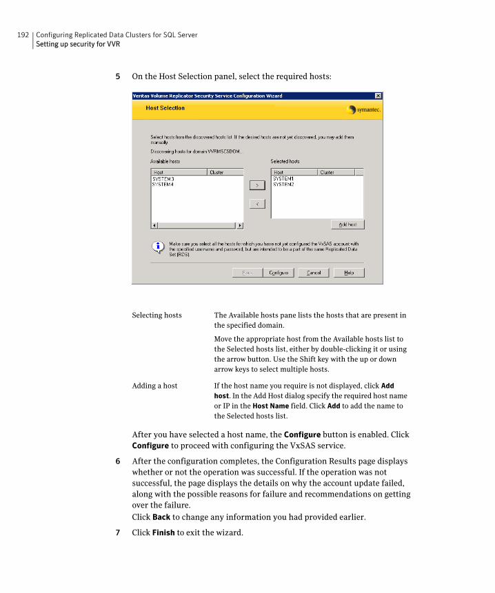
192 Configuring Replicated Data Clusters for SQL ServerSetting up security for VVR
5 On the Host Selection panel, select the required hosts:
After you have selected a host name, the Configure button is enabled. Click Configure to proceed with configuring the VxSAS service.
6 After the configuration completes, the Configuration Results page displays whether or not the operation was successful. If the operation was not successful, the page displays the details on why the account update failed, along with the possible reasons for failure and recommendations on getting over the failure.
Click Back to change any information you had provided earlier.
7 Click Finish to exit the wizard.
Selecting hosts The Available hosts pane lists the hosts that are present in the specified domain.
Move the appropriate host from the Available hosts list to the Selected hosts list, either by double-clicking it or using the arrow button. Use the Shift key with the up or down arrow keys to select multiple hosts.
Adding a host If the host name you require is not displayed, click Add
host. In the Add Host dialog specify the required host name or IP in the Host Name field. Click Add to add the name to the Selected hosts list.
193Configuring Replicated Data Clusters for SQL ServerSetting up the Replicated Data Sets (RDS)
Setting up the Replicated Data Sets (RDS)Set up the Replicated Data Sets (RDS) in the primary zone and secondary zone. You can configure an RDS for both zones using the Setup Replicated Data Set Wizard.
Prerequisites for setting up the RDS for the primary and secondary zones
Before you run the Setup Replicated Data Set Wizard, verify the following:
■ Verify that the data volumes are not of the following types as VVR does not support these types of volumes:
■ Storage Foundation for Windows (software) RAID 5 volumes
■ Volumes with a Dirty Region Log (DRL)
■ Volumes that are already part of another RVG
■ Volumes names containing a comma
■ Verify that the cluster disk group is imported and the volumes are mounted in the primary and secondary zone
■ Verify that you have configured security for VVR
See “Setting up security for VVR” on page 190.
Creating the Replicated Data Sets with the wizard
To create the Replicated Data Set
1 Use the Veritas Enterprise Administrator (VEA) console to launch the Setup Replicated Data Set Wizard from the cluster node on the Primary where the cluster disk group is imported:
Click Start > All Programs > Symantec > Veritas Storage Foundation > Veritas Enterprise Administrator.
From the VEA console, click View > Connection > Replication Network.
2 Right-click Replication Network and select Setup Replicated Data Set.
3 Read the information on the Welcome page and then click Next.
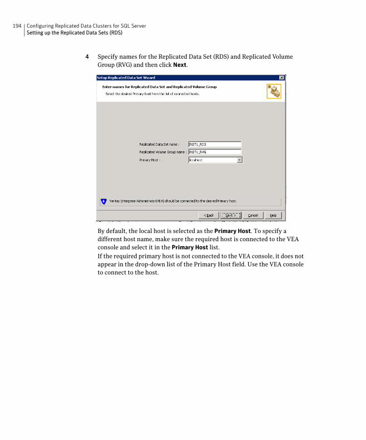
194 Configuring Replicated Data Clusters for SQL ServerSetting up the Replicated Data Sets (RDS)
4 Specify names for the Replicated Data Set (RDS) and Replicated Volume Group (RVG) and then click Next.
By default, the local host is selected as the Primary Host. To specify a different host name, make sure the required host is connected to the VEA console and select it in the Primary Host list.
If the required primary host is not connected to the VEA console, it does not appear in the drop-down list of the Primary Host field. Use the VEA console to connect to the host.
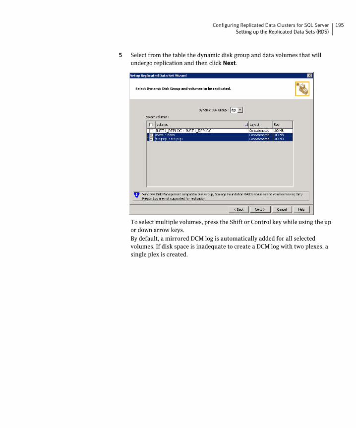
195Configuring Replicated Data Clusters for SQL ServerSetting up the Replicated Data Sets (RDS)
5 Select from the table the dynamic disk group and data volumes that will undergo replication and then click Next.
To select multiple volumes, press the Shift or Control key while using the up or down arrow keys.
By default, a mirrored DCM log is automatically added for all selected volumes. If disk space is inadequate to create a DCM log with two plexes, a single plex is created.
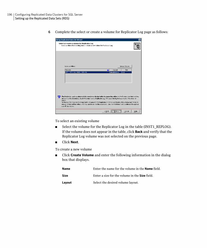
196 Configuring Replicated Data Clusters for SQL ServerSetting up the Replicated Data Sets (RDS)
6 Complete the select or create a volume for Replicator Log page as follows:
To select an existing volume
■ Select the volume for the Replicator Log in the table (INST1_REPLOG).
If the volume does not appear in the table, click Back and verify that the Replicator Log volume was not selected on the previous page.
■ Click Next.
To create a new volume
■ Click Create Volume and enter the following information in the dialog box that displays.
Name Enter the name for the volume in the Name field.
Size Enter a size for the volume in the Size field.
Layout Select the desired volume layout.
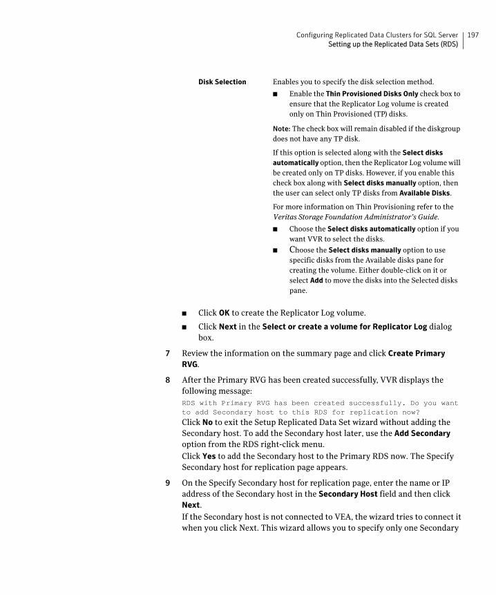
197Configuring Replicated Data Clusters for SQL ServerSetting up the Replicated Data Sets (RDS)
■ Click OK to create the Replicator Log volume.
■ Click Next in the Select or create a volume for Replicator Log dialog box.
7 Review the information on the summary page and click Create Primary RVG.
8 After the Primary RVG has been created successfully, VVR displays the following message:RDS with Primary RVG has been created successfully. Do you want to add Secondary host to this RDS for replication now?
Click No to exit the Setup Replicated Data Set wizard without adding the Secondary host. To add the Secondary host later, use the Add Secondary option from the RDS right-click menu.
Click Yes to add the Secondary host to the Primary RDS now. The Specify Secondary host for replication page appears.
9 On the Specify Secondary host for replication page, enter the name or IP address of the Secondary host in the Secondary Host field and then click Next.
If the Secondary host is not connected to VEA, the wizard tries to connect it when you click Next. This wizard allows you to specify only one Secondary
Disk Selection Enables you to specify the disk selection method.
■ Enable the Thin Provisioned Disks Only check box to ensure that the Replicator Log volume is created only on Thin Provisioned (TP) disks.
Note: The check box will remain disabled if the diskgroup does not have any TP disk.
If this option is selected along with the Select disks
automatically option, then the Replicator Log volume will be created only on TP disks. However, if you enable this check box along with Select disks manually option, then the user can select only TP disks from Available Disks.
For more information on Thin Provisioning refer to the Veritas Storage Foundation Administrator’s Guide.
■ Choose the Select disks automatically option if you want VVR to select the disks.
■ Choose the Select disks manually option to use specific disks from the Available disks pane for creating the volume. Either double-click on it or select Add to move the disks into the Selected disks pane.
198 Configuring Replicated Data Clusters for SQL ServerSetting up the Replicated Data Sets (RDS)
host. Additional Secondary hosts can be added using the Add Secondary option from the RDS right-click menu.
Wait till the connection process is complete and then click Next again.
10 If only a disk group without any data volumes or Replicator Log, as on the Primary host exists on the Secondary, then VVR displays a message. Read the message carefully.
The option to automatically create volumes on the Secondary host is available only if the disks that are part of the disk group have:
■ the same or larger amount of space as that on the Primary
■ Enough space to create volumes with the same layout as on the Primary
Otherwise, the RDS setup wizard enables you to create the required volumes manually.
■ Click Yes to automatically create the Secondary data volumes and the Replicator Log.
■ Click No to create the Secondary data volumes and the Replicator Log manually, using the Volume Information on the connected hosts page.
11 The Volume Information on connected hosts page appears. This page displays information on the availability of volumes on the Secondary nodes, if the Primary and Secondary hosts are connected to VEA.
This page does not appear if all the required volumes that are available on the Primary host are also available on the Secondary hosts.
■ If the required data volumes and the Replicator Log have not been created on the Secondary host, then the page displays the appropriate message against the volume name on the Secondary.
■ If an error occurs or a volume needs to be created, a volume displays with a red icon and a description of the situation. To address the error, or to create a new Replicator Log volume on the secondary site, click the volume on the secondary site, click the available task button and follow the wizard.
Depending on the discrepancies between the volumes on the primary site and the secondary site, you may have to create a new volume, recreate or resize a volume (change attributes), or remove either a DRL or DCM log.
When all the replicated volumes meet the replication requirements and display a green check mark, click Next.
■ If all the data volumes to be replicated meet the requirements, this screen does not occur.
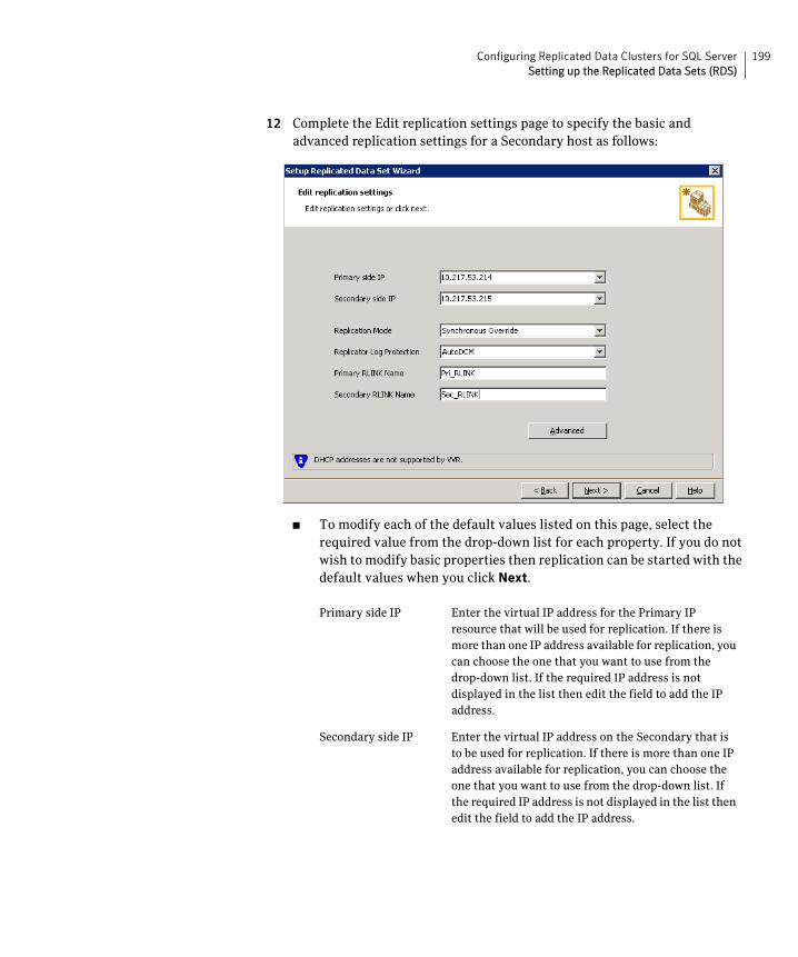
199Configuring Replicated Data Clusters for SQL ServerSetting up the Replicated Data Sets (RDS)
12 Complete the Edit replication settings page to specify the basic and advanced replication settings for a Secondary host as follows:
■ To modify each of the default values listed on this page, select the required value from the drop-down list for each property. If you do not wish to modify basic properties then replication can be started with the default values when you click Next.
Primary side IP Enter the virtual IP address for the Primary IP resource that will be used for replication. If there is more than one IP address available for replication, you can choose the one that you want to use from the drop-down list. If the required IP address is not displayed in the list then edit the field to add the IP address.
Secondary side IP Enter the virtual IP address on the Secondary that is to be used for replication. If there is more than one IP address available for replication, you can choose the one that you want to use from the drop-down list. If the required IP address is not displayed in the list then edit the field to add the IP address.
200 Configuring Replicated Data Clusters for SQL ServerSetting up the Replicated Data Sets (RDS)
Replication Mode Select the required mode of replication: Synchronous
Override, Synchronous, or Asynchronous. The default is synchronous override.Synchronous Override enables synchronous updates under typical operating conditions. If the Secondary site is disconnected from the Primary site, and write operations occur on the Primary site, the mode of replication temporarily switches to Asynchronous.Synchronous determines updates from the application on the Primary site are completed only after the Secondary site successfully receives the updates.Asynchronous determines updates from the application on the Primary site are completed after VVR updates in the Replicator Log. From there, VVR writes the data to the data volume and replicates the updates to the secondary site asynchronously.If the Secondary is set to the synchronous mode of replication and is disconnected, the Primary data volumes with NTFS file systems may be displayed with the status as MISSING.
Replicator Log Protection
The AutoDCM is the default selected mode for the Replicator Log overflow protection when all the volumes in the Primary RVG have a DCM log. The DCM is enabled when the Replicator Log overflows.
The DCM option enables the Replicator Log protection for the Secondary host when the Replicator Log overflows, and the connection between the Primary and Secondary is lost. This option is available only if all the data volumes under the Primary RVG have a DCM Log associated with them.
The Off option disables Replicator Log Overflow protection.
In the case of the Bunker node. Replicator Log protection is set to Off, by default. Thus, if the Primary RLINK overflows due to the Bunker RLINK, then this RLINK is detached.
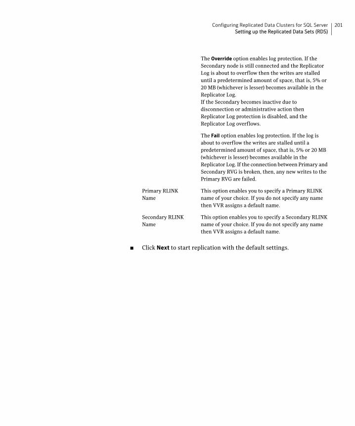
201Configuring Replicated Data Clusters for SQL ServerSetting up the Replicated Data Sets (RDS)
■ Click Next to start replication with the default settings.
The Override option enables log protection. If the Secondary node is still connected and the Replicator Log is about to overflow then the writes are stalled until a predetermined amount of space, that is, 5% or 20 MB (whichever is lesser) becomes available in the Replicator Log.If the Secondary becomes inactive due to disconnection or administrative action then Replicator Log protection is disabled, and the Replicator Log overflows.
The Fail option enables log protection. If the log is about to overflow the writes are stalled until a predetermined amount of space, that is, 5% or 20 MB (whichever is lesser) becomes available in the Replicator Log. If the connection between Primary and Secondary RVG is broken, then, any new writes to the Primary RVG are failed.
Primary RLINK Name
This option enables you to specify a Primary RLINK name of your choice. If you do not specify any name then VVR assigns a default name.
Secondary RLINK Name
This option enables you to specify a Secondary RLINK name of your choice. If you do not specify any name then VVR assigns a default name.
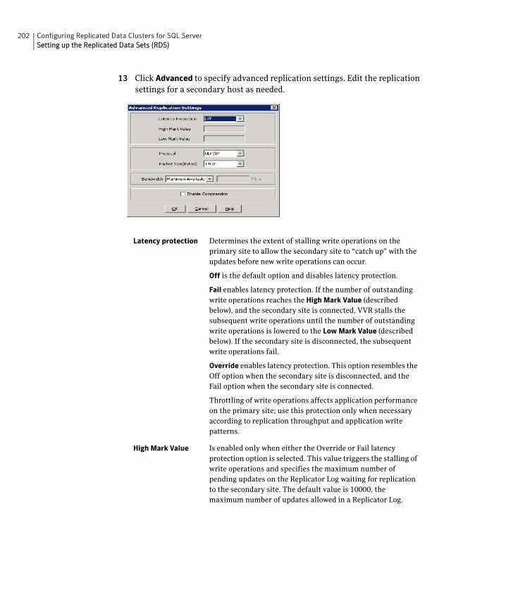
202 Configuring Replicated Data Clusters for SQL ServerSetting up the Replicated Data Sets (RDS)
13 Click Advanced to specify advanced replication settings. Edit the replication settings for a secondary host as needed.
Latency protection Determines the extent of stalling write operations on the primary site to allow the secondary site to “catch up” with the updates before new write operations can occur.
Off is the default option and disables latency protection.
Fail enables latency protection. If the number of outstanding write operations reaches the High Mark Value (described below), and the secondary site is connected, VVR stalls the subsequent write operations until the number of outstanding write operations is lowered to the Low Mark Value (described below). If the secondary site is disconnected, the subsequent write operations fail.
Override enables latency protection. This option resembles the Off option when the secondary site is disconnected, and the Fail option when the secondary site is connected.
Throttling of write operations affects application performance on the primary site; use this protection only when necessary according to replication throughput and application write patterns.
High Mark Value Is enabled only when either the Override or Fail latency protection option is selected. This value triggers the stalling of write operations and specifies the maximum number of pending updates on the Replicator Log waiting for replication to the secondary site. The default value is 10000, the maximum number of updates allowed in a Replicator Log.
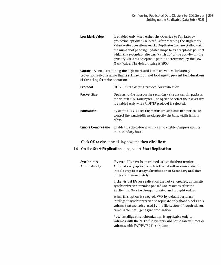
203Configuring Replicated Data Clusters for SQL ServerSetting up the Replicated Data Sets (RDS)
Click OK to close the dialog box and then click Next.
14 On the Start Replication page, select Start Replication.
Low Mark Value Is enabled only when either the Override or Fail latency protection options is selected. After reaching the High Mark Value, write operations on the Replicator Log are stalled until the number of pending updates drops to an acceptable point at which the secondary site can “catch up” to the activity on the primary site; this acceptable point is determined by the Low Mark Value. The default value is 9950.
Caution: When determining the high mark and low mark values for latency protection, select a range that is sufficient but not too large to prevent long durations of throttling for write operations.
Protocol UDP/IP is the default protocol for replication.
Packet Size Updates to the host on the secondary site are sent in packets; the default size 1400 bytes. The option to select the packet size is enabled only when UDP/IP protocol is selected.
Bandwidth By default, VVR uses the maximum available bandwidth. To control the bandwidth used, specify the bandwidth limit in Mbps.
Enable Compression Enable this checkbox if you want to enable Compression for the secondary host.
Synchronize Automatically
If virtual IPs have been created, select the Synchronize
Automatically option, which is the default recommended for initial setup to start synchronization of Secondary and start replication immediately.
If the virtual IPs for replication are not yet created, automatic synchronization remains paused and resumes after the Replication Service Group is created and brought online.
When this option is selected, VVR by default performs intelligent synchronization to replicate only those blocks on a volume that are being used by the file system. If required, you can disable intelligent synchronization.
Note: Intelligent synchronization is applicable only to volumes with the NTFS file systems and not to raw volumes or volumes with FAT/FAT32 file systems.
204 Configuring Replicated Data Clusters for SQL ServerSetting up the Replicated Data Sets (RDS)
■ To add the secondary without starting replication, deselect the Start Replication option. You can start replication later by using the Start Replication option from the Secondary RVG right-click menu.
■ Click Next to display the Summary page.
15 Review the information.
Click Back to change any information you had specified and click Finish to add the secondary host to the RDS and exit the wizard.
Synchronize from Checkpoint
If you want to use this method, then you must first create a checkpoint.
If you have considerable amount of data on the Primary data volumes, then you may first want to synchronize the secondary for existing data using the backup-restore method with checkpoint. After the restore is complete, use the Synchronize from Checkpoint option to start replication from checkpoint to synchronize the secondary with the writes that happened when backup-restore was in progress.
For information on synchronizing from checkpoints, refer Veritas Storage Foundation TM Volume Replicator Administrator's Guide.
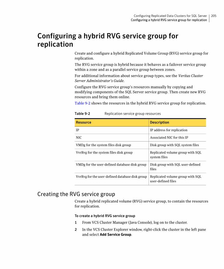
205Configuring Replicated Data Clusters for SQL ServerConfiguring a hybrid RVG service group for replication
Configuring a hybrid RVG service group for replication
Create and configure a hybrid Replicated Volume Group (RVG) service group for replication.
The RVG service group is hybrid because it behaves as a failover service group within a zone and as a parallel service group between zones.
For additional information about service group types, see the Veritas Cluster Server Administrator’s Guide.
Configure the RVG service group’s resources manually by copying and modifying components of the SQL Server service group. Then create new RVG resources and bring them online.
Table 9-2 shows the resources in the hybrid RVG service group for replication.
Creating the RVG service groupCreate a hybrid replicated volume (RVG) service group, to contain the resources for replication.
To create a hybrid RVG service group
1 From VCS Cluster Manager (Java Console), log on to the cluster.
2 In the VCS Cluster Explorer window, right-click the cluster in the left pane and select Add Service Group.
Table 9-2 Replication service group resources
Resource Description
IP IP address for replication
NIC Associated NIC for this IP
VMDg for the system files disk group Disk group with SQL system files
VvrRvg for the system files disk group Replicated volume group with SQL system files
VMDg for the user-defined database disk group Disk group with SQL user-defined files
VvrRvg for the user-defined database disk group Replicated volume group with SQL user-defined files
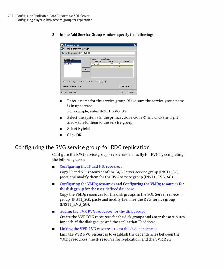
206 Configuring Replicated Data Clusters for SQL ServerConfiguring a hybrid RVG service group for replication
3 In the Add Service Group window, specify the following:
■ Enter a name for the service group. Make sure the service group name is in uppercase.
For example, enter INST1_RVG_SG.
■ Select the systems in the primary zone (zone 0) and click the right arrow to add them to the service group.
■ Select Hybrid.
■ Click OK.
Configuring the RVG service group for RDC replicationConfigure the RVG service group’s resources manually for RVG by completing the following tasks:
■ Configuring the IP and NIC resources
Copy IP and NIC resources of the SQL Server service group (INST1_SG), paste and modify them for the RVG service group (INST1_RVG_SG).
■ Configuring the VMDg resources and Configuring the VMDg resources for the disk group for the user-defined database
Copy the VMDg resources for the disk groups in the SQL Server service group (INST1_SG), paste and modify them for the RVG service group (INST1_RVG_SG).
■ Adding the VVR RVG resources for the disk groups
Create the VVR RVG resources for the disk groups and enter the attributes for each of the disk groups and the replication IP address.
■ Linking the VVR RVG resources to establish dependencies
Link the VVR RVG resources to establish the dependencies between the VMDg resources, the IP resource for replication, and the VVR RVG

207Configuring Replicated Data Clusters for SQL ServerConfiguring a hybrid RVG service group for replication
resources for the disk groups. Configure the RVG service group’s VMDg resources to point to the disk groups that contain the RVGs.
■ Deleting the VMDg resource from the SQL Server service group
Delete the VMDg resources from the SQL Server service group, because they depend on the replication and were configured in the RVG service group.
Configuring the IP and NIC resourcesConfigure the following resources and attributes for the IP and NIC.
Table 9-3 shows the resource attributes to modify.
To create the IP resource and NIC resource
1 In the VCS Cluster Explorer window, select the SQL Server service group (INST1_SG) in the left pane.
2 On the Resources tab, right-click the IP resource (INST1_SG-IP), and click Copy > Self and Child Nodes.
3 In the left pane, select the RVG service group (INST1_RVG_SG).
4 On the Resources tab, right-click in the blank resource display area and click Paste.
5 In the Name Clashes window, change the names of the IP and NIC resources for the RVG service group.
Table 9-3 IP and NIC resources
Resource Attributes to Modify
IP Address
NIC (none)
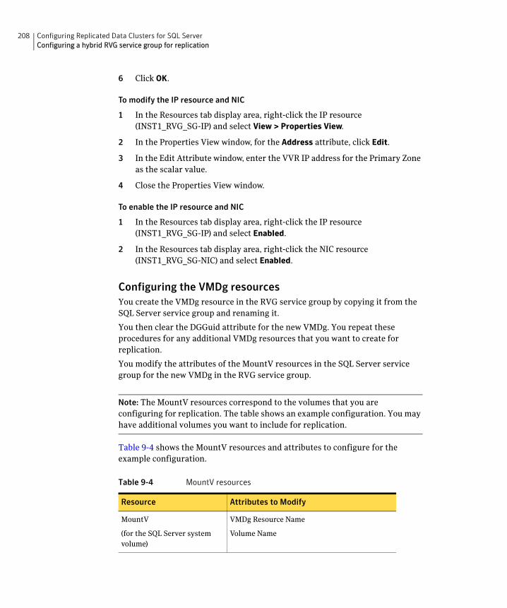
208 Configuring Replicated Data Clusters for SQL ServerConfiguring a hybrid RVG service group for replication
6 Click OK.
To modify the IP resource and NIC
1 In the Resources tab display area, right-click the IP resource (INST1_RVG_SG-IP) and select View > Properties View.
2 In the Properties View window, for the Address attribute, click Edit.
3 In the Edit Attribute window, enter the VVR IP address for the Primary Zone as the scalar value.
4 Close the Properties View window.
To enable the IP resource and NIC
1 In the Resources tab display area, right-click the IP resource (INST1_RVG_SG-IP) and select Enabled.
2 In the Resources tab display area, right-click the NIC resource (INST1_RVG_SG-NIC) and select Enabled.
Configuring the VMDg resourcesYou create the VMDg resource in the RVG service group by copying it from the SQL Server service group and renaming it.
You then clear the DGGuid attribute for the new VMDg. You repeat these procedures for any additional VMDg resources that you want to create for replication.
You modify the attributes of the MountV resources in the SQL Server service group for the new VMDg in the RVG service group.
Note: The MountV resources correspond to the volumes that you are configuring for replication. The table shows an example configuration. You may have additional volumes you want to include for replication.
Table 9-4 shows the MountV resources and attributes to configure for the example configuration.
Table 9-4 MountV resources
Resource Attributes to Modify
MountV
(for the SQL Server system volume)
VMDg Resource Name
Volume Name
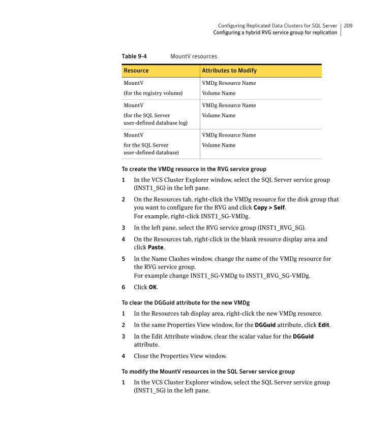
209Configuring Replicated Data Clusters for SQL ServerConfiguring a hybrid RVG service group for replication
To create the VMDg resource in the RVG service group
1 In the VCS Cluster Explorer window, select the SQL Server service group (INST1_SG) in the left pane.
2 On the Resources tab, right-click the VMDg resource for the disk group that you want to configure for the RVG and click Copy > Self.
For example, right-click INST1_SG-VMDg.
3 In the left pane, select the RVG service group (INST1_RVG_SG).
4 On the Resources tab, right-click in the blank resource display area and click Paste.
5 In the Name Clashes window, change the name of the VMDg resource for the RVG service group.
For example change INST1_SG-VMDg to INST1_RVG_SG-VMDg.
6 Click OK.
To clear the DGGuid attribute for the new VMDg
1 In the Resources tab display area, right-click the new VMDg resource.
2 In the same Properties View window, for the DGGuid attribute, click Edit.
3 In the Edit Attribute window, clear the scalar value for the DGGuid attribute.
4 Close the Properties View window.
To modify the MountV resources in the SQL Server service group
1 In the VCS Cluster Explorer window, select the SQL Server service group (INST1_SG) in the left pane.
MountV
(for the registry volume)
VMDg Resource Name
Volume Name
MountV
(for the SQL Server user-defined database log)
VMDg Resource Name
Volume Name
MountV
for the SQL Server user-defined database)
VMDg Resource Name
Volume Name
Table 9-4 MountV resources
Resource Attributes to Modify
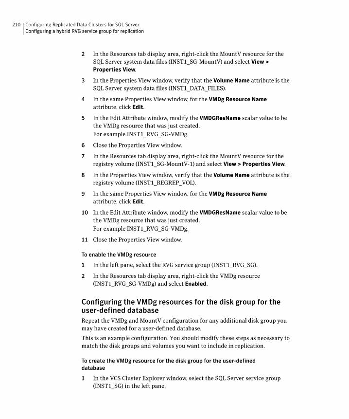
210 Configuring Replicated Data Clusters for SQL ServerConfiguring a hybrid RVG service group for replication
2 In the Resources tab display area, right-click the MountV resource for the SQL Server system data files (INST1_SG-MountV) and select View > Properties View.
3 In the Properties View window, verify that the Volume Name attribute is the SQL Server system data files (INST1_DATA_FILES).
4 In the same Properties View window, for the VMDg Resource Name attribute, click Edit.
5 In the Edit Attribute window, modify the VMDGResName scalar value to be the VMDg resource that was just created.
For example INST1_RVG_SG-VMDg.
6 Close the Properties View window.
7 In the Resources tab display area, right-click the MountV resource for the registry volume (INST1_SG-MountV-1) and select View > Properties View.
8 In the Properties View window, verify that the Volume Name attribute is the registry volume (INST1_REGREP_VOL).
9 In the same Properties View window, for the VMDg Resource Name attribute, click Edit.
10 In the Edit Attribute window, modify the VMDGResName scalar value to be the VMDg resource that was just created.
For example INST1_RVG_SG-VMDg.
11 Close the Properties View window.
To enable the VMDg resource
1 In the left pane, select the RVG service group (INST1_RVG_SG).
2 In the Resources tab display area, right-click the VMDg resource (INST1_RVG_SG-VMDg) and select Enabled.
Configuring the VMDg resources for the disk group for the user-defined databaseRepeat the VMDg and MountV configuration for any additional disk group you may have created for a user-defined database.
This is an example configuration. You should modify these steps as necessary to match the disk groups and volumes you want to include in replication.
To create the VMDg resource for the disk group for the user-defined database
1 In the VCS Cluster Explorer window, select the SQL Server service group (INST1_SG) in the left pane.
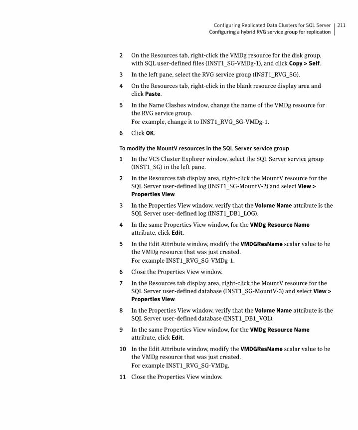
211Configuring Replicated Data Clusters for SQL ServerConfiguring a hybrid RVG service group for replication
2 On the Resources tab, right-click the VMDg resource for the disk group, with SQL user-defined files (INST1_SG-VMDg-1), and click Copy > Self.
3 In the left pane, select the RVG service group (INST1_RVG_SG).
4 On the Resources tab, right-click in the blank resource display area and click Paste.
5 In the Name Clashes window, change the name of the VMDg resource for the RVG service group.
For example, change it to INST1_RVG_SG-VMDg-1.
6 Click OK.
To modify the MountV resources in the SQL Server service group
1 In the VCS Cluster Explorer window, select the SQL Server service group (INST1_SG) in the left pane.
2 In the Resources tab display area, right-click the MountV resource for the SQL Server user-defined log (INST1_SG-MountV-2) and select View > Properties View.
3 In the Properties View window, verify that the Volume Name attribute is the SQL Server user-defined log (INST1_DB1_LOG).
4 In the same Properties View window, for the VMDg Resource Name attribute, click Edit.
5 In the Edit Attribute window, modify the VMDGResName scalar value to be the VMDg resource that was just created.
For example INST1_RVG_SG-VMDg-1.
6 Close the Properties View window.
7 In the Resources tab display area, right-click the MountV resource for the SQL Server user-defined database (INST1_SG-MountV-3) and select View > Properties View.
8 In the Properties View window, verify that the Volume Name attribute is the SQL Server user-defined database (INST1_DB1_VOL).
9 In the same Properties View window, for the VMDg Resource Name attribute, click Edit.
10 In the Edit Attribute window, modify the VMDGResName scalar value to be the VMDg resource that was just created.
For example INST1_RVG_SG-VMDg.
11 Close the Properties View window.
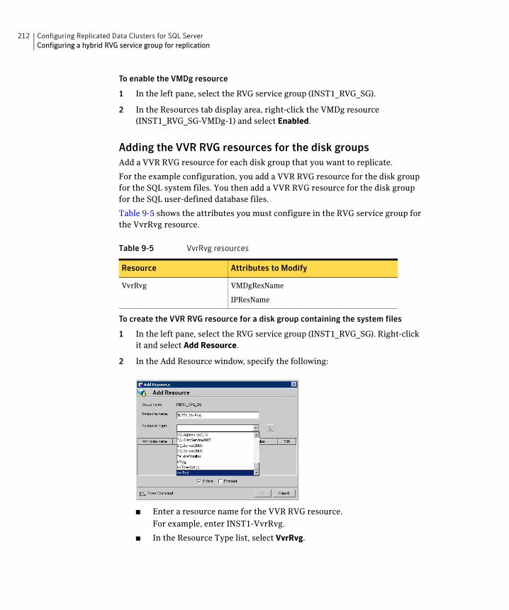
212 Configuring Replicated Data Clusters for SQL ServerConfiguring a hybrid RVG service group for replication
To enable the VMDg resource
1 In the left pane, select the RVG service group (INST1_RVG_SG).
2 In the Resources tab display area, right-click the VMDg resource (INST1_RVG_SG-VMDg-1) and select Enabled.
Adding the VVR RVG resources for the disk groupsAdd a VVR RVG resource for each disk group that you want to replicate.
For the example configuration, you add a VVR RVG resource for the disk group for the SQL system files. You then add a VVR RVG resource for the disk group for the SQL user-defined database files.
Table 9-5 shows the attributes you must configure in the RVG service group for the VvrRvg resource.
To create the VVR RVG resource for a disk group containing the system files
1 In the left pane, select the RVG service group (INST1_RVG_SG). Right-click it and select Add Resource.
2 In the Add Resource window, specify the following:
■ Enter a resource name for the VVR RVG resource.
For example, enter INST1-VvrRvg.
■ In the Resource Type list, select VvrRvg.
Table 9-5 VvrRvg resources
Resource Attributes to Modify
VvrRvg VMDgResName
IPResName
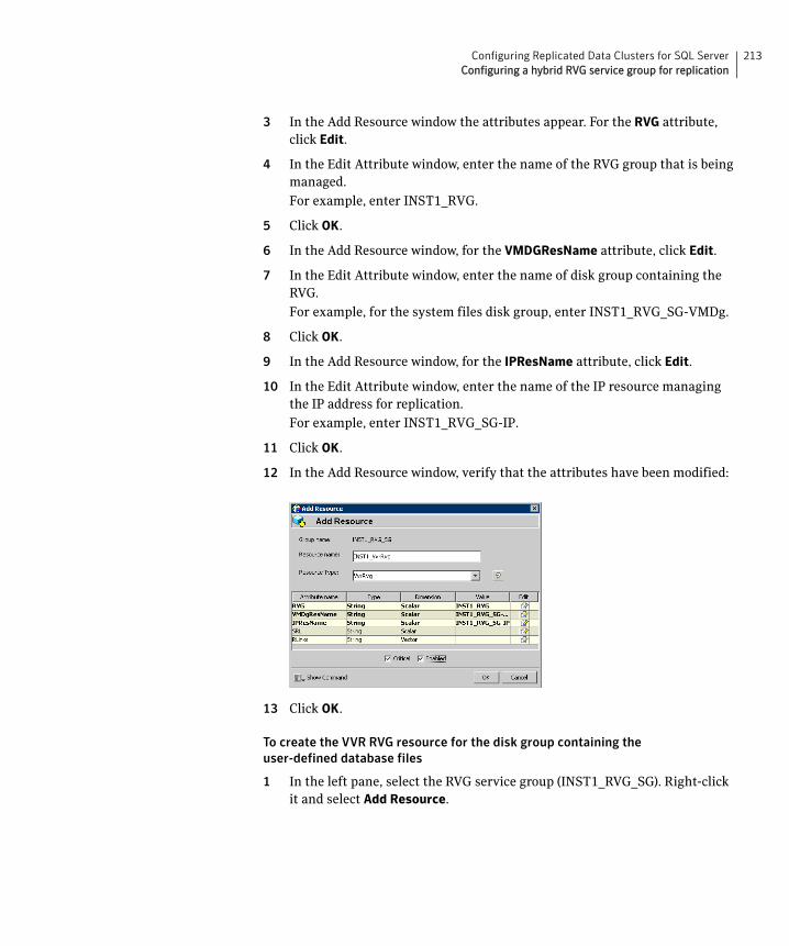
213Configuring Replicated Data Clusters for SQL ServerConfiguring a hybrid RVG service group for replication
3 In the Add Resource window the attributes appear. For the RVG attribute, click Edit.
4 In the Edit Attribute window, enter the name of the RVG group that is being managed.
For example, enter INST1_RVG.
5 Click OK.
6 In the Add Resource window, for the VMDGResName attribute, click Edit.
7 In the Edit Attribute window, enter the name of disk group containing the RVG.
For example, for the system files disk group, enter INST1_RVG_SG-VMDg.
8 Click OK.
9 In the Add Resource window, for the IPResName attribute, click Edit.
10 In the Edit Attribute window, enter the name of the IP resource managing the IP address for replication.
For example, enter INST1_RVG_SG-IP.
11 Click OK.
12 In the Add Resource window, verify that the attributes have been modified:
13 Click OK.
To create the VVR RVG resource for the disk group containing the user-defined database files
1 In the left pane, select the RVG service group (INST1_RVG_SG). Right-click it and select Add Resource.
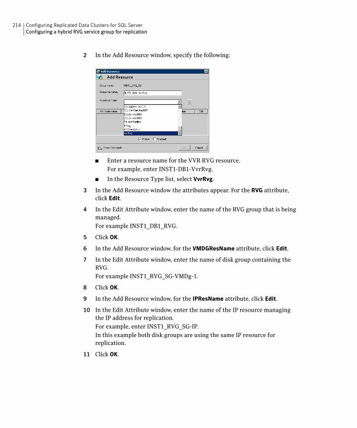
214 Configuring Replicated Data Clusters for SQL ServerConfiguring a hybrid RVG service group for replication
2 In the Add Resource window, specify the following:
■ Enter a resource name for the VVR RVG resource.
For example, enter INST1-DB1-VvrRvg.
■ In the Resource Type list, select VvrRvg.
3 In the Add Resource window the attributes appear. For the RVG attribute, click Edit.
4 In the Edit Attribute window, enter the name of the RVG group that is being managed.
For example INST1_DB1_RVG.
5 Click OK.
6 In the Add Resource window, for the VMDGResName attribute, click Edit.
7 In the Edit Attribute window, enter the name of disk group containing the RVG.
For example INST1_RVG_SG-VMDg-1.
8 Click OK.
9 In the Add Resource window, for the IPResName attribute, click Edit.
10 In the Edit Attribute window, enter the name of the IP resource managing the IP address for replication.
For example, enter INST1_RVG_SG-IP.
In this example both disk groups are using the same IP resource for replication.
11 Click OK.
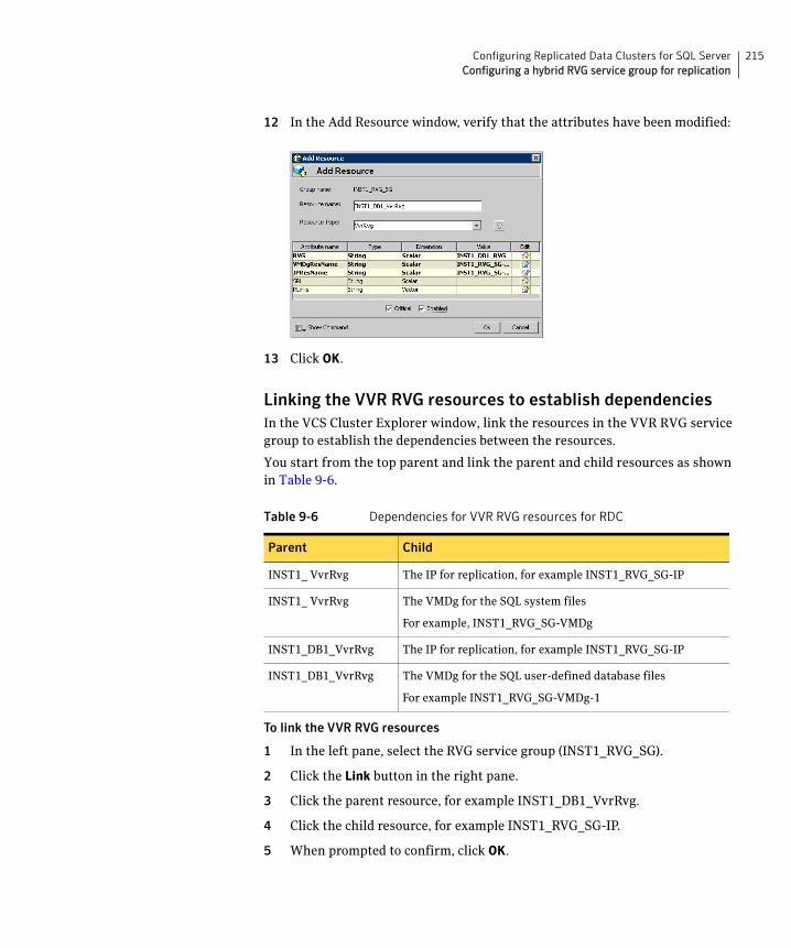
215Configuring Replicated Data Clusters for SQL ServerConfiguring a hybrid RVG service group for replication
12 In the Add Resource window, verify that the attributes have been modified:
13 Click OK.
Linking the VVR RVG resources to establish dependenciesIn the VCS Cluster Explorer window, link the resources in the VVR RVG service group to establish the dependencies between the resources.
You start from the top parent and link the parent and child resources as shown in Table 9-6.
To link the VVR RVG resources
1 In the left pane, select the RVG service group (INST1_RVG_SG).
2 Click the Link button in the right pane.
3 Click the parent resource, for example INST1_DB1_VvrRvg.
4 Click the child resource, for example INST1_RVG_SG-IP.
5 When prompted to confirm, click OK.
Table 9-6 Dependencies for VVR RVG resources for RDC
Parent Child
INST1_ VvrRvg The IP for replication, for example INST1_RVG_SG-IP
INST1_ VvrRvg The VMDg for the SQL system files
For example, INST1_RVG_SG-VMDg
INST1_DB1_VvrRvg The IP for replication, for example INST1_RVG_SG-IP
INST1_DB1_VvrRvg The VMDg for the SQL user-defined database files
For example INST1_RVG_SG-VMDg-1

216 Configuring Replicated Data Clusters for SQL ServerConfiguring a hybrid RVG service group for replication
6 Repeat these steps to link all the RVG resources:
Notice that when you enable a resource and the state of the entity which it is monitoring is online, the corresponding VCS agent reports status for that resource as online. You do not have to bring the resource online manually.
Deleting the VMDg resource from the SQL Server service groupThe VMDg resources must now be manually deleted from the SQL Server service group, because they depend on replication and were configured in the RVG service group.
To delete the VMDg Resources from the SQL Server service group
1 In the VCS Cluster Explorer window, select the SQL Server service group (INST1_SG) from the left pane.
2 In the Resources tab display area, right-click the VMDg resource for the system files disk group (INST1_SG-VMDg) and select Delete.
3 Click Yes to confirm that you want to delete it (even if it is online).
4 In the Resources tab display area, right-click the VMDg resource for the user-defined database disk group (INST1_SG-VMDg-1) and select Delete.
5 Click Yes to confirm that you want to delete it (even if it is online).

217Configuring Replicated Data Clusters for SQL ServerConfiguring a hybrid RVG service group for replication
Configuring the RVGPrimary resourcesAdd resources of type RVGPrimary to the SQL Server service group for each of the SQL Server disk groups (system and user-defined) and configure the attributes.
Set the value of the RvgResourceName attribute to the name of the RVG resource for the RVGPrimary agent.
Table 9-7 shows the RVG Primary resources and attributes you must configure in the SQL Server service group for the sample configuration.
Creating the RVG Primary resourcesFor all disk groups, create an RVG Primary resource for replication.
To create the RVG Primary resource for the SQL Server system disk group
1 In the VCS Cluster Explorer window, right-click the SQL Server service group (INST1_SG) in the left pane, and select Add Resource.
2 In the Add Resource window, specify the following:
■ Enter a resource name for the RVG Primary resource for the SQL Server system files disk group.
Table 9-7 RVG Primary resources
Resource Attributes to Modify
RVGPrimary
(for the disk group for the SQL system files)
RvgResourceName
RVGPrimary
(for the disk group for the SQL user-defined database files)
RvgResourceName
218 Configuring Replicated Data Clusters for SQL ServerConfiguring a hybrid RVG service group for replication
For example, enter INST1_RvgPrimary.
■ Select RVGPrimary as the Resource Type.
3 In the Add Resource window the attributes appear. For the RvgResourceName attribute, click Edit.
4 In the Edit Attribute window, enter the name of the VVR RVG resource, for example INST1_VvrRvg and click OK.
5 If desired, set the AutoTakeover and AutoResync attributes from their defaults.
See the Veritas Cluster Server Administrator’s Guide for more information about the RVG Primary agent.
6 Verify that Critical and Enabled are both checked.
7 Click OK.
To create the RVG Primary resource for the SQL Server user-defined database disk group
1 In the VCS Cluster Explorer window, right-click the SQL Server service group (INST1_SG) in the left pane, and select Add Resource.
2 In the Add Resource window, specify the following:
■ Enter a resource name for the RVG Primary resource for the SQL Server user-defined database disk group.
For example, enter INST1_DB1_RvgPrimary.
■ Select RVGPrimary as the Resource Type.
3 In the Add Resource window the attributes appear. For the RvgResourceName attribute, click Edit.
4 In the Edit Attribute window, enter the name of the VVR RVG resource, for example INST1_DB1_VvrRvg and click OK.
5 If desired, set the AutoTakeover and AutoResync attributes from their defaults.
6 Verify that Critical and Enabled are both checked.
7 Click OK.
Linking the RVG Primary resources to establish dependenciesIn the VCS Cluster Explorer window, link the resources in the SQL Server service group (INST1_SG) to establish the dependencies between the resources for replication.
219Configuring Replicated Data Clusters for SQL ServerConfiguring a hybrid RVG service group for replication
You start from the top parent and link the parent and child resources as shown in Table 9-8.
To link the RVG Primary resources
1 In the left pane, select the SQL Server service group (INST1_SG).
2 Click the Link button in the right pane.
3 Click the parent resource.
For example INST1_ SG-MountV.
4 Click the child resource.
For example INST1_RvgPrimary.
5 When prompted to confirm, click OK.
6 Repeat these steps to link all the RVG Primary resources.
Bringing the RVG Primary resources onlineIn the VCS Cluster Explorer window, bring the RVG Primary resources in the SQL Server service group (INST1_SG) online on the first node in the primary zone.
To bring the RVG Primary resources online
1 In the left pane, select the SQL Server service group (INST1_SG).
2 In the right pane on the Resources tab, right-click the first RVG Primary resource (INST1_RvgPrimary) and select Online > SYSTEM1.
3 In the right pane on the Resources tab, right click the second RVG Primary resource (INST1_DB1_RvgPrimary) and select Online > SYSTEM1.
Table 9-8 Dependencies for the RVG Primary resources for RDC
Parent Child
INST1_ SG-MountV INST1_RvgPrimary
INST1_ SG-MountV-1 INST1_RvgPrimary
INST1_ SG-MountV-2 INST1_DB1_RvgPrimary
INST1_ SG-MountV-3 INST1_DB1_RvgPrimary
220 Configuring Replicated Data Clusters for SQL ServerSetting a dependency between the service groups
Configuring the primary system zone for the RVGIn the RVG service group, set up systems in the primary zone (zone 0) to specify that initial failover occurs to systems within the primary zone for the RVG service group.
To configure the primary system zone for the RVG service group
1 From VCS Cluster Explorer, in the left pane, select the RVG service group (INST1_RVG_SG).
2 In the right pane, select the Properties tab.
3 In the Properties pane, click the button Show All Attributes.
4 In the Attributes View, scroll down and select the SystemZones attribute.
5 Click the Edit icon for the SystemZones attribute.
6 In the Edit Attribute dialog box, click the plus sign and enter the systems and the zone number (zone 0) for the primary zone.
7 Click OK.
Setting a dependency between the service groupsThe RVG service group must be online on both the primary and secondary zones. However, if a failover occurs from one node to another within the same zone, the RVG service group must fail over along with the application service group.
To ensure that the SQL Server service group and the RVG service group fail over and switch together, set up an online local hard dependency from the RVG service group to the SQL Server service group.
The SQL service group (for example, INST1_SG) is dependent on the replication service group (for example, INST1_RVG_GRP).
To set up an online local hard dependency
1 From VCS Cluster Explorer, in the left pane, select the cluster (MYCLUSTER).
2 In the right pane, select the Service Groups tab.
3 Click the Link button to create a dependency between service groups.
4 Click the application service group (parent service group).
For example, click the SQL Server service group INST1_ SG.
5 Click the RVG service group (the child resource).
For example, click the RVG service group INST1_RVG_SG.
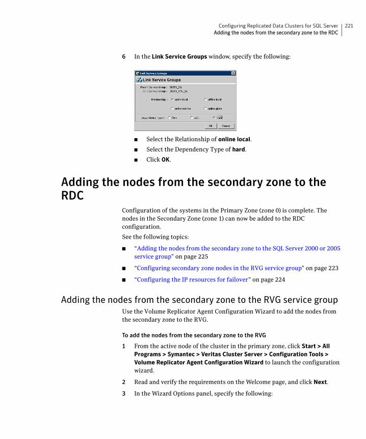
221Configuring Replicated Data Clusters for SQL ServerAdding the nodes from the secondary zone to the RDC
6 In the Link Service Groups window, specify the following:
■ Select the Relationship of online local.
■ Select the Dependency Type of hard.
■ Click OK.
Adding the nodes from the secondary zone to the RDC
Configuration of the systems in the Primary Zone (zone 0) is complete. The nodes in the Secondary Zone (zone 1) can now be added to the RDC configuration.
See the following topics:
■ “Adding the nodes from the secondary zone to the SQL Server 2000 or 2005 service group” on page 225
■ “Configuring secondary zone nodes in the RVG service group” on page 223
■ “Configuring the IP resources for failover” on page 224
Adding the nodes from the secondary zone to the RVG service groupUse the Volume Replicator Agent Configuration Wizard to add the nodes from the secondary zone to the RVG.
To add the nodes from the secondary zone to the RVG
1 From the active node of the cluster in the primary zone, click Start > All Programs > Symantec > Veritas Cluster Server > Configuration Tools > Volume Replicator Agent Configuration Wizard to launch the configuration wizard.
2 Read and verify the requirements on the Welcome page, and click Next.
3 In the Wizard Options panel, specify the following:
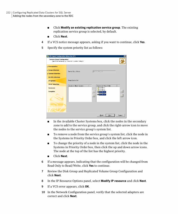
222 Configuring Replicated Data Clusters for SQL ServerAdding the nodes from the secondary zone to the RDC
■ Click Modify an existing replication service group. The existing replication service group is selected, by default.
■ Click Next.
4 If a VCS notice message appears, asking if you want to continue, click Yes.
5 Specify the system priority list as follows:
■ In the Available Cluster Systems box, click the nodes in the secondary zone to add to the service group, and click the right-arrow icon to move the nodes to the service group’s system list.
■ To remove a node from the service group’s system list, click the node in the Systems in Priority Order box, and click the left arrow icon.
■ To change the priority of a node in the system list, click the node in the Systems in Priority Order box, then click the up and down arrow icons. The node at the top of the list has the highest priority.
■ Click Next.
6 If a message appears, indicating that the configuration will be changed from Read Only to Read/Write, click Yes to continue.
7 Review the Disk Group and Replicated Volume Group Configuration and click Next.
8 In the IP Resource Options panel, select Modify IP resource and click Next.
9 If a VCS error appears, click OK.
10 In the Network Configuration panel, verify that the selected adapters are correct and click Next.
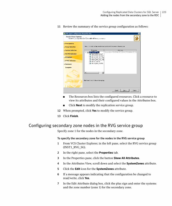
223Configuring Replicated Data Clusters for SQL ServerAdding the nodes from the secondary zone to the RDC
11 Review the summary of the service group configuration as follows:
■ The Resources box lists the configured resources. Click a resource to view its attributes and their configured values in the Attributes box.
■ Click Next to modify the replication service group.
12 When prompted, click Yes to modify the service group.
13 Click Finish.
Configuring secondary zone nodes in the RVG service groupSpecify zone 1 for the nodes in the secondary zone.
To specify the secondary zone for the nodes in the RVG service group
1 From VCS Cluster Explorer, in the left pane, select the RVG service group (INST1_RVG_SG).
2 In the right pane, select the Properties tab.
3 In the Properties pane, click the button Show All Attributes.
4 In the Attributes View, scroll down and select the SystemZones attribute.
5 Click the Edit icon for the SystemZones attribute.
6 If a message appears indicating that the configuration be changed to read/write, click Yes.
7 In the Edit Attribute dialog box, click the plus sign and enter the systems and the zone number (zone 1) for the secondary zone.
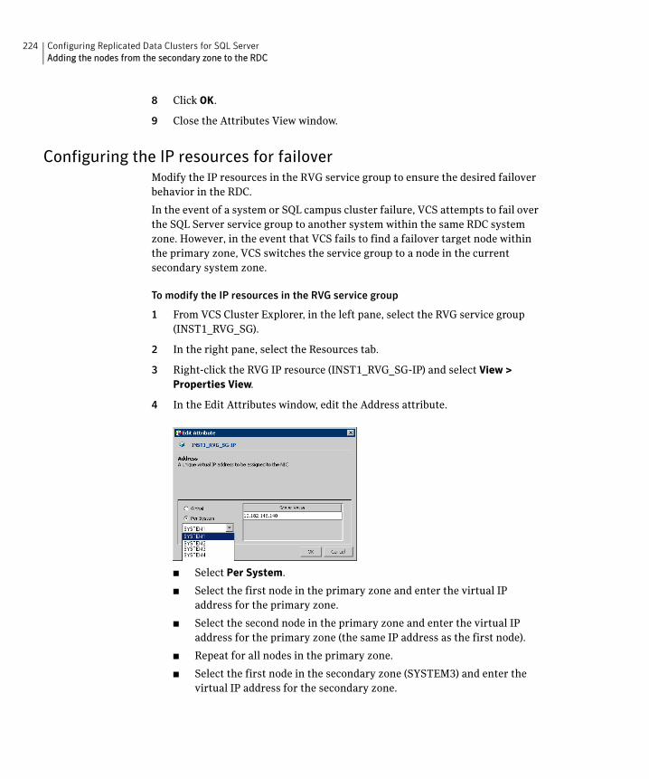
224 Configuring Replicated Data Clusters for SQL ServerAdding the nodes from the secondary zone to the RDC
8 Click OK.
9 Close the Attributes View window.
Configuring the IP resources for failoverModify the IP resources in the RVG service group to ensure the desired failover behavior in the RDC.
In the event of a system or SQL campus cluster failure, VCS attempts to fail over the SQL Server service group to another system within the same RDC system zone. However, in the event that VCS fails to find a failover target node within the primary zone, VCS switches the service group to a node in the current secondary system zone.
To modify the IP resources in the RVG service group
1 From VCS Cluster Explorer, in the left pane, select the RVG service group (INST1_RVG_SG).
2 In the right pane, select the Resources tab.
3 Right-click the RVG IP resource (INST1_RVG_SG-IP) and select View > Properties View.
4 In the Edit Attributes window, edit the Address attribute.
■ Select Per System.
■ Select the first node in the primary zone and enter the virtual IP address for the primary zone.
■ Select the second node in the primary zone and enter the virtual IP address for the primary zone (the same IP address as the first node).
■ Repeat for all nodes in the primary zone.
■ Select the first node in the secondary zone (SYSTEM3) and enter the virtual IP address for the secondary zone.
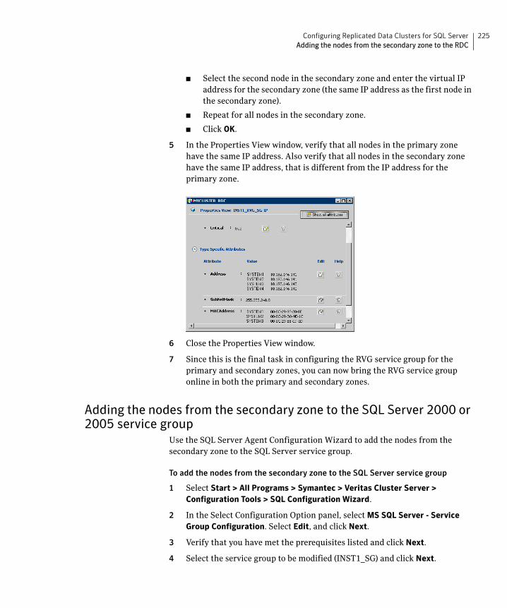
225Configuring Replicated Data Clusters for SQL ServerAdding the nodes from the secondary zone to the RDC
■ Select the second node in the secondary zone and enter the virtual IP address for the secondary zone (the same IP address as the first node in the secondary zone).
■ Repeat for all nodes in the secondary zone.
■ Click OK.
5 In the Properties View window, verify that all nodes in the primary zone have the same IP address. Also verify that all nodes in the secondary zone have the same IP address, that is different from the IP address for the primary zone.
6 Close the Properties View window.
7 Since this is the final task in configuring the RVG service group for the primary and secondary zones, you can now bring the RVG service group online in both the primary and secondary zones.
Adding the nodes from the secondary zone to the SQL Server 2000 or 2005 service group
Use the SQL Server Agent Configuration Wizard to add the nodes from the secondary zone to the SQL Server service group.
To add the nodes from the secondary zone to the SQL Server service group
1 Select Start > All Programs > Symantec > Veritas Cluster Server > Configuration Tools > SQL Configuration Wizard.
2 In the Select Configuration Option panel, select MS SQL Server - Service Group Configuration. Select Edit, and click Next.
3 Verify that you have met the prerequisites listed and click Next.
4 Select the service group to be modified (INST1_SG) and click Next.
226 Configuring Replicated Data Clusters for SQL ServerAdding the nodes from the secondary zone to the RDC
5 If a VCS notice message appears indicating that resources are online, click Yes to continue.
6 On the Service Group Configuration panel, select the nodes in the secondary zone, use the arrow button to move them from Available Cluster Systems to Systems in Priority Order.
To change the priority of a system in the Systems in Priority Order list, select the system and click the up and down arrow icons. Arrange the systems in priority order in as failover targets for the group. The server that needs to come online first must be at the top of the list followed by the next one that will be brought online.
This set of nodes selected for the SQL Server service group must be the same as the nodes selected for the RVG service group. Ensure that the nodes are also in the same priority order.
7 Click Next.
8 On the SQL Server Instance Selection panel, click Next.
9 The User Databases List panel summarizes the databases for this instance of SQL. Click Next.
10 On the Detail Monitoring Configuration panel, clear the box in the SQL Instance List to disable monitoring, as required. Detailed monitoring is not necessary. Click Next.
11 On the Registry Replication Path panel, click Next.
12 On the Virtual Server Configuration panel, verify that the public adapter is used on each system and click Next.
13 In the Service Group Summary, review the service group configuration and click Next.
14 A message appears if the configuration is currently in the Read Only mode. Click Yes to make the configuration read and write enabled. The wizard validates the configuration and modifies it.
15 Click Finish.
Configuring the zones in the SQL Server service groupSpecify zone 1 for the nodes in the secondary zone.
To specify the secondary zone for the nodes in the SQL Server service group
1 From VCS Cluster Explorer, in the left pane, select the SQL Server service group (INST1_SG).
2 In the right pane, select the Properties tab.
227Configuring Replicated Data Clusters for SQL ServerVerifying the RDC configuration
3 In the Properties pane, click the button Show All Attributes.
4 In the Attributes View, scroll down and select the SystemZones attribute.
5 Click the Edit icon for the SystemZones attribute.
6 If a message appears indicating that the configuration be changed to read/write, click Yes.
7 In the Edit Attribute dialog box, click the plus sign and enter the systems and the zone number (zone 1) for the secondary zone.
8 Click OK.
9 Close the Attributes View window.
Verifying the RDC configurationAfter completing all the configuration tasks for the primary and secondary zones, you can bring the service group online, then verify the configuration.
Perform the following tasks:
■ Bringing the service group online
■ Switching online nodes
Bringing the service group onlineAfter completing all configuration, ensure that the RVG service group is online in both the primary and secondary zone. Then you can bring the SQL service group online in the primary zone.
To bring the SQL service group online
1 From VCS Cluster Explorer, in the left pane, right-click the SQL Server service group.
2 Click Online.
Switching online nodesFailover simulation is an important part of configuration testing. Test the failover by switching online nodes.
The RVG service group is online in both the primary and secondary zone. However, within a zone, if more than node is configured, the RVG service group should fail over with the application service group.
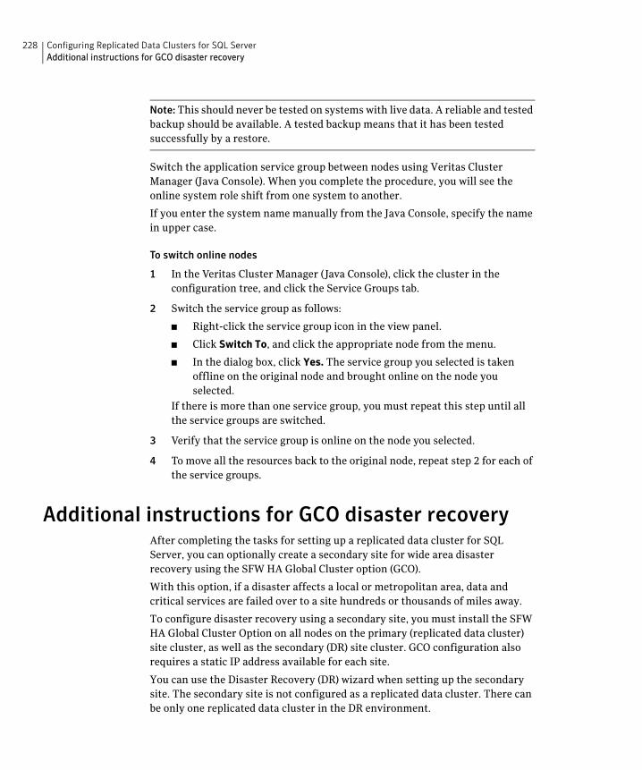
228 Configuring Replicated Data Clusters for SQL ServerAdditional instructions for GCO disaster recovery
Note: This should never be tested on systems with live data. A reliable and tested backup should be available. A tested backup means that it has been tested successfully by a restore.
Switch the application service group between nodes using Veritas Cluster Manager (Java Console). When you complete the procedure, you will see the online system role shift from one system to another.
If you enter the system name manually from the Java Console, specify the name in upper case.
To switch online nodes
1 In the Veritas Cluster Manager (Java Console), click the cluster in the configuration tree, and click the Service Groups tab.
2 Switch the service group as follows:
■ Right-click the service group icon in the view panel.
■ Click Switch To, and click the appropriate node from the menu.
■ In the dialog box, click Yes. The service group you selected is taken offline on the original node and brought online on the node you selected.
If there is more than one service group, you must repeat this step until all the service groups are switched.
3 Verify that the service group is online on the node you selected.
4 To move all the resources back to the original node, repeat step 2 for each of the service groups.
Additional instructions for GCO disaster recoveryAfter completing the tasks for setting up a replicated data cluster for SQL Server, you can optionally create a secondary site for wide area disaster recovery using the SFW HA Global Cluster option (GCO).
With this option, if a disaster affects a local or metropolitan area, data and critical services are failed over to a site hundreds or thousands of miles away.
To configure disaster recovery using a secondary site, you must install the SFW HA Global Cluster Option on all nodes on the primary (replicated data cluster) site cluster, as well as the secondary (DR) site cluster. GCO configuration also requires a static IP address available for each site.
You can use the Disaster Recovery (DR) wizard when setting up the secondary site. The secondary site is not configured as a replicated data cluster. There can be only one replicated data cluster in the DR environment.
229Configuring Replicated Data Clusters for SQL ServerAdditional instructions for GCO disaster recovery
The DR wizard does the following tasks:
■ Clones the storage
■ Clones the application service group
■ Sets up VVR replication for the secondary site
■ Configures the primary and secondary site clusters as global clusters
See “Disaster recovery configuration” on page 49.

230 Configuring Replicated Data Clusters for SQL ServerAdditional instructions for GCO disaster recovery
Chapter
10Configuring disaster recovery for SQL Server
This chapter contains the following topics:
■ Tasks for configuring disaster recovery for SQL Server
■ Guidelines for installing SFW HA and configuring the cluster on the secondary site
■ Verifying your primary site configuration
■ Setting up your replication environment
■ Assigning user privileges (secure clusters only)
■ Configuring disaster recovery with the DR wizard
■ Cloning the storage on the secondary site using the DR wizard (VVR replication option)
■ Creating temporary storage on the secondary site using the DR wizard (array-based replication)
■ Installing and configuring SQL Server on the secondary site
■ Cloning the service group configuration from the primary to the secondary site
■ Configuring replication and global clustering
■ Verifying the disaster recovery configuration
■ Establishing secure communication within the global cluster (optional)
■ Adding multiple DR sites (optional)
■ Recovery procedures for service group dependencies
232 Configuring disaster recovery for SQL ServerTasks for configuring disaster recovery for SQL Server
Tasks for configuring disaster recovery for SQL Server
After setting up an SFW HA high availability environment for SQL on a primary site, you can create a secondary or “failover” site for disaster recovery.
The Disaster Recovery (DR) wizard helps you to clone the storage and service group configuration from the primary site to the secondary site. You can install the application on the secondary site during the DR wizard workflow.
The DR wizard also helps you set up replication and the global clustering (GCO option). You can choose to configure replication using Veritas Volume Replicator (VVR) or an agent-supported array-based hardware replication. The DR wizard can configure required options for the VCS agents for EMC SRDF and for Hitachi TrueCopy. To use the wizard with any other agent-supported array-based replication, you must complete configuring global clustering with the wizard before configuring replication on the array.
The DR wizard is available from the Solutions Configuration Center. Symantec recommends using the Solutions Configuration Center as a guide for installing and configuring disaster recovery.
This document covers how to use the DR wizard to configure disaster recovery. However, if necessary, you can configure disaster recovery manually. To do so, you first configure the high availability for SQL Server on both sites. (You can configure high availability for MSDTC either before or after configuring high availability for Microsoft SQL.) You then configure the disaster recovery components: Veritas Volume Replicator (VVR) and the Global Cluster Option. You also have the choice of using array-based hardware replication for your disaster recovery solution. See the Veritas Cluster Server Administrator’s Guide for information on configuring the Global Cluster Option. See the Veritas Volume Replicator Administrator’s Guide for information on configuring VVR. For information on configuring array-based hardware replication, see the VCS hardware agent documentation for the particular array you want to configure.
Table 10-1 shows the steps specific to the DR configuration that are done after configuring high availability on the primary zone.
Table 10-1 Configuring the secondary site for disaster recovery
Action Description
Install SFW HA and configure the cluster on the secondary site
Caution: Ensure that the name you assign to the secondary site cluster is different from the name assigned to the primary site cluster.
See “Guidelines for installing SFW HA and configuring the cluster on the secondary site” on page 236.
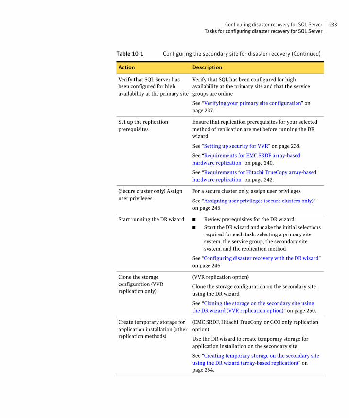
233Configuring disaster recovery for SQL ServerTasks for configuring disaster recovery for SQL Server
Verify that SQL Server has been configured for high availability at the primary site
Verify that SQL has been configured for high availability at the primary site and that the service groups are online
See “Verifying your primary site configuration” on page 237.
Set up the replication prerequisites
Ensure that replication prerequisites for your selected method of replication are met before running the DR wizard
See “Setting up security for VVR” on page 238.
See “Requirements for EMC SRDF array-based hardware replication” on page 240.
See “Requirements for Hitachi TrueCopy array-based hardware replication” on page 242.
(Secure cluster only) Assign user privileges
For a secure cluster only, assign user privileges
See “Assigning user privileges (secure clusters only)” on page 245.
Start running the DR wizard ■ Review prerequisites for the DR wizard
■ Start the DR wizard and make the initial selections required for each task: selecting a primary site system, the service group, the secondary site system, and the replication method
See “Configuring disaster recovery with the DR wizard” on page 246.
Clone the storage configuration (VVR replication only)
(VVR replication option)
Clone the storage configuration on the secondary site using the DR wizard
See “Cloning the storage on the secondary site using the DR wizard (VVR replication option)” on page 250.
Create temporary storage for application installation (other replication methods)
(EMC SRDF, Hitachi TrueCopy, or GCO only replication option)
Use the DR wizard to create temporary storage for application installation on the secondary site
See “Creating temporary storage on the secondary site using the DR wizard (array-based replication)” on page 254.
Table 10-1 Configuring the secondary site for disaster recovery (Continued)
Action Description
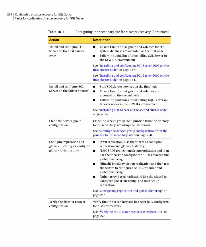
234 Configuring disaster recovery for SQL ServerTasks for configuring disaster recovery for SQL Server
Install and configure SQL Server on the first cluster node
■ Ensure that the disk group and volumes for the system database are mounted on the first node
■ Follow the guidelines for installing SQL Server in the SFW HA environment
See “Installing and configuring SQL Server 2005 on the first cluster node” on page 147.
See “Installing and configuring SQL Server 2000 on the first cluster node” on page 144.
Install and configure SQL Server on the failover node(s)
■ Stop SQL Server services on the first node
■ Ensure that the disk group and volumes are mounted on the second node
■ Follow the guidelines for installing SQL Server on failover nodes in the SFW HA environment
See “Installing SQL Server on the second cluster node” on page 149.
Clone the service group configuration
Clone the service group configuration from the primary to the secondary site using the DR wizard
See “Cloning the service group configuration from the primary to the secondary site” on page 258.
Configure replication and global clustering, or configure global clustering only
■ (VVR replication) Use the wizard to configure replication and global clustering
■ (EMC SRDF replication) Set up replication and then use the wizard to configure the SRDF resource and global clustering
■ (Hitachi TrueCopy) Set up replication and then use the wizard to configure the HTC resource and global clustering
■ (Other array-based replication) Use the wizard to configure global clustering, and then set up replication
See “Configuring replication and global clustering” on page 262.
Verify the disaster recover configuration
Verify that the secondary site has been fully configured for disaster recovery
See “Verifying the disaster recovery configuration” on page 278.
Table 10-1 Configuring the secondary site for disaster recovery (Continued)
Action Description
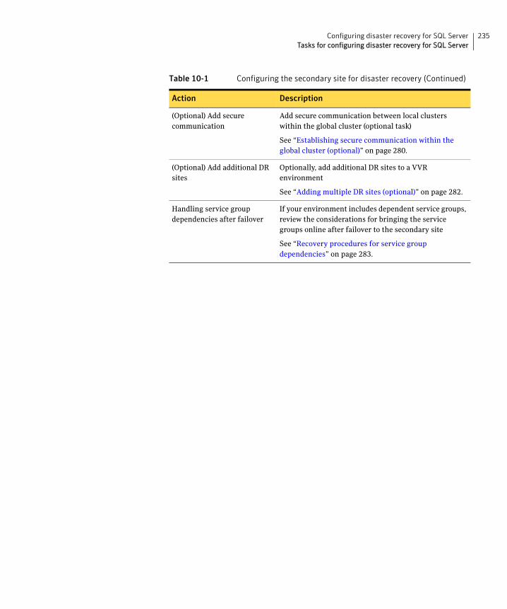
235Configuring disaster recovery for SQL ServerTasks for configuring disaster recovery for SQL Server
(Optional) Add secure communication
Add secure communication between local clusters within the global cluster (optional task)
See “Establishing secure communication within the global cluster (optional)” on page 280.
(Optional) Add additional DR sites
Optionally, add additional DR sites to a VVR environment
See “Adding multiple DR sites (optional)” on page 282.
Handling service group dependencies after failover
If your environment includes dependent service groups, review the considerations for bringing the service groups online after failover to the secondary site
See “Recovery procedures for service group dependencies” on page 283.
Table 10-1 Configuring the secondary site for disaster recovery (Continued)
Action Description
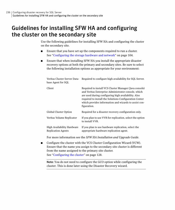
236 Configuring disaster recovery for SQL ServerGuidelines for installing SFW HA and configuring the cluster on the secondary site
Guidelines for installing SFW HA and configuring the cluster on the secondary site
Use the following guidelines for installing SFW HA and configuring the cluster on the secondary site.
■ Ensure that you have set up the components required to run a cluster.
See “Configuring the storage hardware and network” on page 104.
■ Ensure that when installing SFW HA you install the appropriate disaster recovery options at both the primary and secondary sites. Be sure to select the following installation options as appropriate for your environment:
For more information see the SFW HA Installation and Upgrade Guide.
■ Configure the cluster with the VCS Cluster Configuration Wizard (VCW). Ensure that the name you assign to the secondary site cluster is different from the name assigned to the primary site cluster.
See “Configuring the cluster” on page 128.
Note: You do not need to configure the GCO option while configuring the cluster. This is done later using the Disaster Recovery wizard.
Veritas Cluster Server Data-base Agent for SQL
Required to configure high availability for SQL Server.
Client Required to install VCS Cluster Manager (Java console) and Veritas Enterprise Administrator console, which are used during configuring high availability. Also required to install the Solutions Configuration Center which provides information and wizards to assist con-figuration.
Global Cluster Option Required for a disaster recovery configuration only.
Veritas Volume Replicator If you plan to use VVR for replication, select the option to install VVR.
High Availability Hardware Replication Agents
If you plan to use hardware replication, select the appropriate hardware replication agent.
237Configuring disaster recovery for SQL ServerVerifying your primary site configuration
Verifying your primary site configurationBefore you begin configuring disaster recovery, make sure that SQL Server has been configured for high availability at the primary site. If you have not yet configured SQL for high availability at the primary site, go to High Availability (HA) Configuration in the Solutions Configuration Center and follow the steps in the order shown.
See “High availability (HA) configuration (New Server)” on page 35.
See “High availability (HA) configuration (Existing Server)” on page 38.
To verify the configuration, use the Cluster Manager (Java console) on the primary site and check the status of the service group in the tree view. Verify that all the resources are online.
Note: If you are setting up a replicated data cluster at the primary site, use the replicated data cluster instructions rather than the high availability configuration steps in the Solutions Configuration Center. See “VCS Replicated Data Cluster configuration” on page 45.
Setting up your replication environmentThe DR wizard can assist you with setting up replication for the following methods of replication:
■ Veritas Volume Replicator (VVR)
■ EMC SRDF
■ Hitachi TrueCopy
For array-based hardware replication, you can use any replication agent supported by Veritas Cluster Server. The DR wizard can help with configuring the methods listed above. If you choose a different replication method, you must run the wizard first to complete configuring global clustering; then afterwards, you configure replication separately.
See “Configuring global clustering only” on page 276.
Before configuring replication with the wizard, ensure that you set up the replication environment prerequisites.
Choose from the following topics, depending on which replication method you are using:
■ “Setting up security for VVR” on page 238
■ “Requirements for EMC SRDF array-based hardware replication” on page 240
238 Configuring disaster recovery for SQL ServerSetting up your replication environment
■ “Requirements for Hitachi TrueCopy array-based hardware replication” on page 242
Setting up security for VVRIf you are using Veritas Volume Replicator (VVR) replication, you must configure the VxSAS service on all cluster nodes. For a disaster recovery environment, you configure the service on all nodes on both the primary and secondary sites.
Complete the following procedure to configure the VxSAS service for VVR.
The procedure has these prerequisites:
■ You must be logged on with administrative privileges on the server for the wizard to be launched.
■ The account you specify must have administrative and log-on as service privileges on all the specified hosts.
■ Avoid specifying blank passwords. In a Windows Server environment, accounts with blank passwords are not supported for log-on service privileges.
■ Make sure that the hosts on which you want to configure the VxSAS service are accessible from the local host.
Note: The VxSAS wizard will not be launched automatically after installing SFW or SFW HA. You must launch this wizard manually to complete the VVR security service configuration. For details on this required service, see Veritas Storage Foundation Veritas Volume Replicator Administrator’s Guide.
To configure the VxSAS service
1 Launch the VVR Security Service Configuration Wizard.
Click Start > All Programs > Symantec > Veritas Storage Foundation > Configuration Wizards > VVR Security Service Configuration Wizard.
or
Type vxsascfg.exe at the command prompt.
2 Read the information provided on the Welcome page and click Next.
3 Complete the Account Information panel as follows and then click Next:
Account name (domain\account)
Enter the administrative account name.
Password Specify a password.
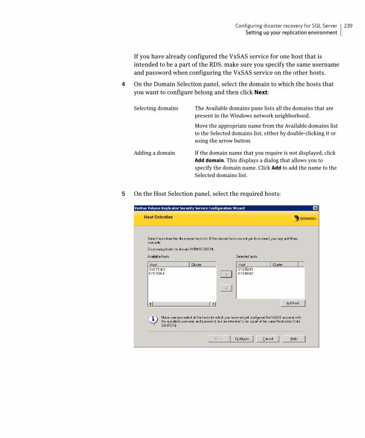
239Configuring disaster recovery for SQL ServerSetting up your replication environment
If you have already configured the VxSAS service for one host that is intended to be a part of the RDS, make sure you specify the same username and password when configuring the VxSAS service on the other hosts.
4 On the Domain Selection panel, select the domain to which the hosts that you want to configure belong and then click Next:
5 On the Host Selection panel, select the required hosts:
Selecting domains The Available domains pane lists all the domains that are present in the Windows network neighborhood.
Move the appropriate name from the Available domains list to the Selected domains list, either by double-clicking it or using the arrow button.
Adding a domain If the domain name that you require is not displayed, click Add domain. This displays a dialog that allows you to specify the domain name. Click Add to add the name to the Selected domains list.
240 Configuring disaster recovery for SQL ServerSetting up your replication environment
After you have selected a host name, the Configure button is enabled. Click Configure to proceed with configuring the VxSAS service.
6 After the configuration completes, the Configuration Results page displays whether or not the operation was successful. If the operation was not successful, the page displays the details on why the account update failed, along with the possible reasons for failure and recommendations on getting over the failure.
Click Back to change any information you had provided earlier.
7 Click Finish to exit the wizard.
Requirements for EMC SRDF array-based hardware replicationThe DR wizard configures the settings required for the VCS hardware replication agent for EMC SRDF. The wizard configures the required settings for the SRDF resource in the VCS application service group. The wizard also configures the Symm heartbeat. Optional resource settings are left in the default state.
For more information about the EMC SRDF agent functions and the configuration options, see Veritas Cluster Server Hardware Replication Agent for EMC SRDF, Configuration Guide.
Before using the DR wizard, review the following topics:
■ “Software requirements for configuring EMC SRDF” on page 240
■ “Replication requirements for EMC SRDF” on page 241
Software requirements for configuring EMC SRDF
The EMC SRDF agent supports SYMCLI versions that EMC recommends for the firmware on the array. The agent supports SRDF on all microcode levels on all
Selecting hosts The Available hosts pane lists the hosts that are present in the specified domain.
Move the appropriate host from the Available hosts list to the Selected hosts list, either by double-clicking it or using the arrow button. Use the Shift key with the up or down arrow keys to select multiple hosts.
Adding a host If the host name you require is not displayed, click Add
host. In the Add Host dialog specify the required host name or IP in the Host Name field. Click Add to add the name to the Selected hosts list.
241Configuring disaster recovery for SQL ServerSetting up your replication environment
Symmetrix arrays, provided that the host/HBA/array combination is in EMC’s hardware compatibility list.
To use the DR wizard to configure the required agent settings for EMC SRDF, ensure that the following software requirements are met:
■ The EMC Solutions Enabler is installed on all cluster nodes.
■ The SYMCLI version that is installed supports the generation of XML output.
■ The SYMCLI version and the microcode level support dynamic swapping.
■ The VCS EMC SRDF agent is installed on all cluster nodes.
Replication requirements for EMC SRDFBefore it performs any tasks, the wizard validates the array configuration as follows:
■ On the primary site, the wizard verifies that no devices are RDF2.
■ On the secondary site, the wizard verifies that no devices are RDF1.
Otherwise, the wizard displays an invalid configuration message and is unable to proceed.
The DR wizard does not start or stop replication. Array replication configuration is not a prerequisite for the wizard to perform storage cloning or service group cloning.
After the service group cloning task is complete, the DR wizard displays a screen describing the following replication requirements:
■ All disks in SFW disk groups must belong to the same device group.
■ The device group must not span more than one array (no composite device groups).
■ A device group can contain one or more disk groups.
■ Dynamic swap must be enabled on both sites.
■ On the primary site:
■ All devices must be RDF1 and part of an RDF1 device group.
■ Devices must have write access.
■ On the secondary site:
■ All devices must be RDF2 and part of an RDF2 device group.
■ Write access must be disabled.
242 Configuring disaster recovery for SQL ServerSetting up your replication environment
It is recommended that you ensure that these requirements are met before proceeding with the wizard. The wizard then validates the array replication configuration.
If replication is configured correctly, the wizard populates the resource configuration screen with the required replication settings for the SRDF resource.
If the replication configuration does not meet the requirements, the wizard leaves the fields on the resource configuration screen blank. You can optionally enter the resource configuration information in the wizard and configure the array replication requirements later. The information you enter is applied only to the SRDF resource, not to the array configuration. However, the SRDF resource will be unable to come online in the service group until replication has been configured correctly.
In addition, note the following agent requirement:
■ Device group configuration must be the same on all nodes of the cluster.
Requirements for Hitachi TrueCopy array-based hardware replication
The DR wizard configures the settings required for the VCS hardware replication agent for Hitachi TrueCopy. The wizard configures the required settings for the HTC resource in the VCS application service group. Optional settings are left in the default state.
For more information about the Hitachi TrueCopy agent functions and the configuration options, see Veritas Cluster Server Hardware Replication Agent for Hitachi TrueCopy, Configuration Guide.
Before using the DR wizard, review the following topics:
■ “Software requirements for Hitachi TrueCopy” on page 242
■ “Replication requirements for Hitachi TrueCopy” on page 243
Software requirements for Hitachi TrueCopy
The Hitachi TrueCopy agent supports all versions of Hitachi RAID Manager.
For details, see Veritas Cluster Server Hardware Replication Agent for Hitachi TrueCopy, Configuration Guide.
To use the DR wizard to configure the required agent settings for Hitachi TrueCopy, ensure that the following requirements are met:
■ RAID Manager is installed in the same location on all nodes on a site.
243Configuring disaster recovery for SQL ServerSetting up your replication environment
■ Enter the primary and secondary site file paths for the horcm files on the Hitachi TrueCopy Path Information panel in the wizard. The default location is:
System Driver\Windows
■ The horcm files are named horcmnn.conf (where nn is a positive number without a leading zero, for example, horcm1.conf but not horcm01.conf).
Replication requirements for Hitachi TrueCopyBefore it performs any tasks, the wizard validates the array configuration as follows:
■ On the primary site, the wizard verifies that all devices are the same type, but not S-SWS or SSUS.
■ On the secondary site, the wizard verifies that all devices are the same type, but not P-VOL or PSUS.
Otherwise, the wizard displays an invalid configuration message and does not proceed.
The DR wizard does not start or stop replication. Array replication configuration is not a prerequisite for the wizard to perform storage cloning or service group cloning.
After the service group cloning task is complete, the DR wizard displays a screen describing the following replication requirements:
■ All configured instances are running.
■ No disks in the SFW disk group span across the Device Group.
■ A device group can contain one or more disk groups.
■ The device group does not span more than one array.
■ At the primary site, all devices are of the type P-VOL.
■ At the secondary site, all devices are of the type S-VOL.
■ All device groups at the primary site are paired to an IP address which must be online on the secondary node.
■ Device group and device names include only alphanumeric characters or the underscore character.
It is recommended that you ensure that these requirements are met before proceeding with the wizard. The wizard then validates the array replication configuration.
If replication is configured correctly, the wizard populates the resource configuration screen with the required replication settings for the HTC resource.

244 Configuring disaster recovery for SQL ServerSetting up your replication environment
If the replication configuration does not meet the requirements, the wizard leaves the fields on the resource configuration screen blank. You can optionally enter the resource configuration information in the wizard and configure the array replication requirements later. The information you enter is applied only to the HTC resource, not to the array configuration. However, the HTC resource will be unable to come online in the service group until replication has been configured correctly.
245Configuring disaster recovery for SQL ServerAssigning user privileges (secure clusters only)
Assigning user privileges (secure clusters only)In order to enable remote cluster operations you must configure a VCS user with the same name and privileges in each cluster.
When assigning privileges in secure clusters, you must specify fully-qualified user names, in the format username@domain. You cannot assign or change passwords for users when VCS is running in secure mode.
You must assign service group rights to the SQL Server service group as well as any dependent service groups except for the RVG service group.
See the Veritas Cluster Server Administrator’s Guide.
To assign user privileges at the primary site
1 Set the configuration to read/write mode:haconf -makerw
2 Add the user. Specify the name in the format [email protected] -add user [-priv <Administrator|Operator>]
3 Modify the attribute of the service group to add the user. Specify the SQL Server service group and any dependent service groups except for the RVG service group.hauser -add user [-priv <Administrator|Operator> [-group
service_groups]]
4 Reset the configuration to read-only: haconf -dump -makero
To assign user privileges at the secondary site
1 Set the configuration to read/write mode:haconf -makerw
2 Add the user. Specify the name in the format [email protected] -add user [-priv <Administrator|Operator>]
3 Reset the configuration to read-only: haconf -dump -makero
246 Configuring disaster recovery for SQL ServerConfiguring disaster recovery with the DR wizard
Configuring disaster recovery with the DR wizardThe Disaster Recovery Configuration Wizard (DR wizard) assists you to perform the following tasks for the selected service group:
■ Clone the storage configuration (VVR replication) or prepare a temporary storage configuration for application installation (array-based hardware replication)
■ Clone the service group
■ Optionally, configure VVR replication, or configure the VCS hardware replication agent settings for EMC SRDF or Hitachi TrueCopy
■ Configure global clustering
Warning: To use the Disaster Recovery Configuration Wizard in an array-based hardware replication environment that is not configured by the wizard, you must first run the wizard to configure global clustering before configuring replication.
The wizard allows you to exit after the logical completion of each task. Each time you re-start the wizard, you specify the primary site system, service group, secondary site system, and replication method, as described in the following procedure. Clicking Next then takes you to the start page of the process following the one that you had last completed.
The DR Wizard list of service groups shows only those that contain a MountV resource. For a dependent service group to be listed, the parent service group must also contain a MountV resource.
Warning: Once you have completed configuring replication and global clustering with the DR wizard, you cannot use the wizard to change the method of replication.
Before running the DR wizard to configure disaster recovery, ensure that you meet the following prerequisites:
■ SFW HA is installed and a cluster is configured at the secondary site. Ensure that the name assigned to the secondary site cluster is different than the name assigned to the primary site cluster.
■ Your application or server role is configured for HA at the primary site and all required services are running at the primary site.
■ The clusters taking part in the DR configuration should have distinct names.
247Configuring disaster recovery for SQL ServerConfiguring disaster recovery with the DR wizard
■ (SQL Server 2000 or 2005 only) After SQL Server is installed on the secondary site, SQL Server Full-Text Search service on the secondary site is configured to start in the manual mode and is initially in the stopped state.
■ Enough free disk space is available at the secondary site to duplicate the storage configuration at the primary site.
■ One static IP address is available per application service group to be cloned.
■ If using VVR for replication, a minimum of one static IP address per site is available for each application instance running in the cluster.
■ Global Cluster Option (GCO) is installed at the primary and secondary site, and one static IP address is available at each site for configuring GCO.
■ A VCS user is configured with the same name and privileges in each cluster.
■ If a firewall exists between the wizard and any systems it needs access to, the firewall is set to allow both ingoing and outgoing TCP requests on port 7419.
Note: The DR wizard does not support VVR configurations that include a Bunker secondary site.
In addition, see the following replication prerequisites, depending on the replication method you are using:
■ “Setting up security for VVR” on page 238
■ “Requirements for EMC SRDF array-based hardware replication” on page 240
■ “Requirements for Hitachi TrueCopy array-based hardware replication” on page 242
To start configuring disaster recovery with the DR wizard
1 Start the DR Configuration Wizard from the Solutions Configuration Center. Click Start > All Programs > Symantec > Veritas Cluster Server > Solutions Configuration Center. Expand the Solutions for Microsoft SQL Server tab and click Disaster Recovery Configuration > Configure Disaster Recovery > Disaster Recovery Configuration Wizard.
Note: By design, the DR wizard requires specific settings for the Lanman attributes on the primary and secondary sites. Before beginning the DR configuration, the wizard checks for these values, and if they are not set as required, the wizard will automatically proceed with setting these values, both at the primary and secondary sites.
248 Configuring disaster recovery for SQL ServerConfiguring disaster recovery with the DR wizard
2 In the Welcome panel, review the prerequisites to ensure that they are met and click Next.
3 In the System Selection panel, complete the requested information:
Click Next.
4 In the Service Group Selection panel, select the service group that you want to clone to the secondary site.
You can choose to clone only the parent service group by not selecting the dependent service group. Only online and local dependencies are supported, in soft, firm, or hard configurations. The wizard can configure only one level of dependency. In a VVR environment, the wizard configures a dependency for the RVG service group, so no other dependency is supported.
The panel lists only service groups that contain a MountV resource.
Click Next.
5 In the Secondary System Selection panel, enter the Fully Qualified Host Name (FQHN) or the IP address of the secondary system for which you want to configure disaster recovery.
Click Next.
System Name Enter the IP address or Fully Qualified Host Name (FQHN) of the primary system where the SQL instance is online.
If you have launched the wizard on the system where the instance is online at the primary site, you can also specify localhost to connect to the system.
249Configuring disaster recovery for SQL ServerConfiguring disaster recovery with the DR wizard
6 In the Replication Options panel, select the replication method. Although you must select the replication method now, configuring replication and the global cluster option is done later, after service group cloning.
Configure Veritas Volume Replicator (VVR) and the Global Cluster Option (GCO)
Select this option if you want to configure VVR replication.
Select this option even if you plan to configure VVR replication or the GCO option manually. This option is required for the wizard to configure the storage cloning correctly for a VVR environment.
The wizard verifies each configuration task and recognizes if a task has been completed successfully.
You cannot mix replication methods. That is, if your primary site is using array-based replication, and you select the VVR option, the wizard will warn you that you cannot use VVR replication for the disaster recovery site.
Configure EMC SRDF and the Global Cluster Option (GCO)
Select this replication option if you want to configure the settings for the VCS EMC SRDF agent. All disks used for the service group on the primary site must belong to an EMC SRDF array.
Select this option even if you plan to configure EMC SRDF replication or the GCO option manually. The wizard verifies each configuration task and recognizes if a task has been completed successfully.
Configure Hitachi TrueCopy and the Global Cluster Option (GCO)
Select this replication option if you want to configure the settings for the VCS Hitachi TrueCopy agent. All disks used for the service group on the primary site must belong to a Hitachi TrueCopy array.
Select this option even if you configure GCO manually. The wizard verifies each configuration task and recognizes if a task has been completed successfully.
250 Configuring disaster recovery for SQL ServerCloning the storage on the secondary site using the DR wizard (VVR replication option)
Click Next.
7 Continue with the next DR configuration task.
For VVR replication, see “Cloning the storage on the secondary site using the DR wizard (VVR replication option)” on page 250.
For array-based replication, see “Creating temporary storage on the secondary site using the DR wizard (array-based replication)” on page 254.
Cloning the storage on the secondary site using the DR wizard (VVR replication option)
The DR wizard enables you to clone the storage configuration present at the primary site on to the secondary site. To do this successfully, the systems at the secondary site must have adequate free storage. If you have created the configuration but there is a mismatch in the volume sizes, the wizard can correct this and then complete the configuration.
If you have not yet started the wizard, see the following topic for the wizard prerequisites before continuing with the storage cloning procedure:
■ “Configuring disaster recovery with the DR wizard” on page 246.
To clone the storage configuration from the primary site to the secondary site (VVR replication method)
1 If you have not yet done so, start the Disaster Recovery Configuration Wizard and specify the information for the primary site system, the service group, and the secondary site system. In the Replication Options panel, select the VVR replication method and click Next.
Configure the Global Cluster Option (GCO) only
If you select this option, the DR wizard does not configure any replication settings. It configures the global cluster option.
Select this option if you want to use the wizard in an array-based replication environment that is not supported by this wizard. You must configure replication manually after you finish the wizard.
If you select the GCO only option, the DR wizard sets up the storage and service group configuration on the secondary site for an array-based hardware replication environment. Therefore, you cannot use this option to clone the storage and service group for a VVR replication environment.
251Configuring disaster recovery for SQL ServerCloning the storage on the secondary site using the DR wizard (VVR replication option)
2 Review the information in the Storage Validation Results panel. This panel compares the configuration at the secondary site with that on the primary. If the storage is already configured identically on both sites, the panel shows that results are identical. Otherwise, the panel shows the differences and recommended actions. You can toggle between a summary and detailed view of information about the differences.
The detailed view shows the following:
The summary view shows the following:
If the panel displays a message indicating that the available disks are inadequate to clone the primary site configuration on the secondary, you
Disk Group Displays the disk group name that needs to be created on the secondary site.
Volume Displays the list of volumes, if necessary, that need to be created at the secondary site.
Size Displays the size of the volume that needs to be created on the secondary site.
Mount Displays the mount to be assigned the volume on the secondary site.
Recommended Action
Indicates the action that needs to be taken at the secondary to make the configuration similar to that on the primary.
■ If the volume does not exist, a new volume will be created.
■ If the volume exists but is of a smaller size than that on the primary, the volume will be expanded to the required size.
■ If the volume is of a greater size than that on the primary, the volume will be recreated using the appropriate size.
■ If the volume is the same as that on the primary, the message indicates that the volumes are identical and no action is required.
Disk groups that do not exist
Displays the names of any disk groups that exist on the primary but do not exist on the secondary.
Existing disk groups that need modification
Displays the names of any disk groups on the secondary that need to be modified to match the primary.
Free disks present on secondary
Displays the list of free disks that exist on the secondary along with details about the free space and total disk space information.
252 Configuring disaster recovery for SQL ServerCloning the storage on the secondary site using the DR wizard (VVR replication option)
can free some disks on the secondary or add more storage. Then click Refresh/Validate to have the wizard update its information about the secondary storage configuration.
You continue with the wizard to provide information for the recommended actions. Before proceeding to the service group configuration, the wizard ensures that the configuration of the disk groups and volumes for the service group is the same at the primary and secondary site.
Click Next.
3 In the Disk Selection for Storage Cloning panel, for each of the disk groups that does not exist or is not same as the corresponding disk group at the primary site, select disks that the wizard can use to create the respective disk groups at the secondary site.
Click Next.
4 In the Volume Layout for Secondary Site Storage panel, complete the requested information:
Selecting Disks For each of the disk groups that needs to be created, select the required disks from the Available Disks pane. Either double-click on the host name or the >> option to move the hosts into the Selected disks pane.
Under the Available Disks label, a drop-down list allows you to filter available disks by disk enclosure name. The default is All, which displays all free disks available on all enclosures.
Disk Group Displays the disk group name to which the volume belongs.
Volume (Volume Size) Displays the name and the size of the volume, corresponding to that on the primary, that needs to be created on the secondary.
Available Disks Select the disks on which you want the wizard to create the volumes. From the Available Disks pane, either double-click on the disk name or the >> option to move the disks into the Selected Disks pane. For each disk group the Available disks pane displays the list of disks that are part of the disk group.
Select disks for each unavailable volume that you want to clone on to the secondary.
Layout By default, the same layout as the one specified for the primary volume is selected. Click Edit to change the layout to suit your specific requirements.
Selected Disks Displays the list of disks that have been moved in from the Available Disks pane.
253Configuring disaster recovery for SQL ServerCloning the storage on the secondary site using the DR wizard (VVR replication option)
Click Next.
5 In the Storage Configuration Cloning Summary panel, review the displayed information. If you want to change any selection, click Back. Otherwise, click Next to allow the wizard to implement the storage configuration at the secondary site.
6 In the Implementation panel, wait until the status for all the completed tasks is marked with a check symbol, indicating successful completion. Wait until the wizard completes cloning the storage. The progress bar indicates the status of the tasks. If some task could not be completed successfully, then the task is marked with an (x) symbol. The Information column displays details about the reasons for task failure. Click Next.
7 In the Storage Cloning Configuration Result screen, view the results and click Next.
8 In the SQL Server Installation panel, review the information. If the application is already installed on the secondary site nodes, click Next to proceed with service group cloning. Otherwise, proceed with installation on the required nodes as follows:
■ Before you begin installation, ensure that your disk groups are imported and volumes are mounted. If volumes were mounted as drive paths (folder mount) on the primary site, the wizard does not mount the volumes on the secondary site. You must manually format the volumes and assign the drive path to the volumes using Veritas Enterprise Administrator. Use the same letters and folder names that were assigned on the primary site.
■ The system may get restarted when the SQL installation is complete. Therefore, if you are running the DR wizard from a system where you need to install SQL, click Finish to exit the wizard before proceeding with installation. Afterwards, restart the Disaster Recovery wizard and continue through the wizard from the Welcome panel.
■ If the DR Wizard is run from a remote node, you can keep the wizard running on that node while you install the application locally on each of the required nodes. Once application installation is complete, click Next to proceed with service group cloning.
.
View Primary Layout Displays the volume layout at the primary site. Use this information as a reference to specify the details for the Secondary layout.
254 Configuring disaster recovery for SQL ServerCreating temporary storage on the secondary site using the DR wizard (array-based replication)
Creating temporary storage on the secondary site using the DR wizard (array-based replication)
To enable you to install applications, the DR wizard can create a temporary disk group, DR_APP_INSTALL__DG, which contains the volumes and mount points for use in application installation. The temporary configuration uses 500 MB volumes or the volume size at the primary site, depending on which is smaller. The wizard deletes the temporary configuration after application installation.
If you have already installed the application on all nodes, you can skip this storage cloning step by unchecking the Perform storage cloning box on the Storage Cloning panel.
If you have not yet started the wizard, see the following topic for the wizard prerequisites before continuing with the procedure:
■ “Configuring disaster recovery with the DR wizard” on page 246.
To create temporary storage for application installation (array-based replication)
1 If you have not yet done so, start the Disaster Recovery Configuration Wizard and specify the information for the primary site system, the service group, and the secondary site system.
2 In the Replication Options panel, select the array-based replication method you plan to use and click Next:
■ EMC SRDF
■ Hitachi TrueCopy
■ Global Cluster Option only (select if you are using another agent-supported array-based replication method)
3 If you selected Hitachi TrueCopy replication, the Hitachi TrueCopy File Paths panel is displayed. The wizard populates the fields if it locates the files in the default location. Otherwise, fill in the file path information for both the primary and secondary sites as follows:
RAID Manager bin path Path to the RAID Manager Command Line interface
Default: C:\HORCM\etc
where C is the system drive.
255Configuring disaster recovery for SQL ServerCreating temporary storage on the secondary site using the DR wizard (array-based replication)
4 In the Storage Cloning panel, you can choose whether or not to perform storage cloning, which creates a temporary storage disk group and volumes for application installation. The wizard will delete the temporary storage once you confirm application installation is complete.
Choose one of the following:
■ If you have not yet installed the application on all nodes, leave Perform storage cloning checked and click Next. Continue with the next step in this procedure.
■ If you have already installed the application on all nodes, uncheck Perform storage cloning and click Next. Continue with the procedure for service group cloning.
5 The Storage Validation Results panel shows the temporary storage configuration that the wizard will configure at the secondary site. You can click Show Summary to toggle to a summary view and toggle back to a detailed view by clicking Show Details.
The detailed view shows the following:
The summary view shows the following:.
HORCM files location Path to the horcm configuration files (horcmnn.conf)
Default: C:\Windows
where C is the system drive
An horcm configuration file is required by the RAID Manager on all nodes; however the wizard does not validate this.
Disk Group Displays the name of the single disk group required on the secondary site for temporary storage:
DR_APP_INSTALL__DG
Volume Displays the list of volumes required at the secondary site.
Size Displays the size of the volumes required on the secondary site.
Mount Displays the mounts required at the secondary site.
Recommended Action
Indicates the action that the wizard will take at the secondary site.
Existing configuration
Displays the existing secondary configuration.
256 Configuring disaster recovery for SQL ServerCreating temporary storage on the secondary site using the DR wizard (array-based replication)
If the panel displays a message indicating that the available disks on the secondary are inadequate, you can free some disks on the secondary or add more storage. Then click Refresh/Validate so that the wizard can update its information about the secondary storage configuration.
Click Next.
6 In the Disk Selection for Storage Cloning panel, a default disk selection is shown for the temporary storage at the secondary site. You can change the selection by moving disks to and from the Available Disks and Selected Disks pane. Under the Available Disks label, a drop-down list allows you to filter available disks by disk enclosure name. The default is All, which displays all free disks available on all enclosures. Click Next.
7 The Volume Layout for Secondary Site Storage panel shows a default volume layout for the temporary storage based on the primary site volume layout. Optionally, you can change the default disk assignment and layout for any volume:
Click Next.
8 In the Storage Configuration Cloning Summary panel, review the displayed information. If you want to change any selection, click Back. Otherwise, click Next to allow the wizard to implement the temporary storage configuration at the secondary site.
Free disks present on secondary
Displays the list of free disks that exist on the secondary along with details about the free space and total disk space information.
Disk Group Displays the DR_APP_INSTALL__DG disk group.
Volume (Volume Size) Displays the name and the size of the volume to be created on the secondary.
Available Disks Displays the disks that are available for the volumes. To select a disk, either double-click on the host name or click the >> button to move the hosts into the Selected Disks pane.
Layout By default, the same layout as the one specified for the primary volume is selected. Click Edit to change the layout to suit your specific requirements.
Selected Disks Displays the list of disks that have been selected for the volume. To remove a disk from the list, select it and click the << button.
View Primary Layout Displays the volume layout at the primary site.
257Configuring disaster recovery for SQL ServerCreating temporary storage on the secondary site using the DR wizard (array-based replication)
9 In the Implementation panel, wait until the status for all the completed tasks is marked with a check symbol, indicating successful completion. Wait until the wizard completes cloning the storage. The progress bar indicates the status of the tasks. If some task could not be completed successfully, then the task is marked with an (x) symbol. The Information column displays details about the reasons for task failure. Click Next.
10 In the Storage Configuration Cloning Result screen, view the results and click Next.
11 In the SQL Server Installation panel, review the information and do one of the following:
■ Before you begin installation, ensure that your disk groups are imported and volumes are mounted. If volumes were mounted as drive paths (folder mount) on the primary site, the wizard does not mount the volumes on the secondary site. You must manually format the volumes and assign the drive path to the volumes using Veritas Enterprise Administrator. Use the same letters and folder names that were assigned on the primary site.
■ The system may get restarted when the SQL installation is complete. Therefore, if you are running the DR wizard from a system where you need to install SQL, click Finish to exit the wizard and proceed with installing the application on the required nodes. Afterwards, restart the Disaster Recovery wizard and continue through the wizard from the Welcome panel.
■ If the DR Wizard is run from a remote node, you can keep the wizard running on that node while you install the application locally on each of the required nodes. Once application installation is complete, click Next to proceed with service group cloning.
Once the application is installed, the temporary cloned storage is no longer needed. Before beginning service group cloning, the wizard displays the Temporary Storage Deletion panel to confirm the deletion of the temporary storage.
258 Configuring disaster recovery for SQL ServerInstalling and configuring SQL Server on the secondary site
Installing and configuring SQL Server on the secondary site
Use the same installation and configuration procedures for SQL Server as on the primary site but note the following considerations when installing SQL Server on the secondary site.
■ Before installing Microsoft SQL Server, verify that the cluster disk group is imported to the first node and the volumes are mounted. If volumes were mounted as drive paths (folder mount) on the primary site, the DR Wizard does not mount the volumes on the secondary site and you must format the volumes and mount them manually.
See “About managing disk groups and volumes” on page 125.
■ During installation, use the same instance name as on the primary site.
Cloning the service group configuration from the primary to the secondary site
The Disaster Recovery Configuration Wizard enables you to create a SQL Server service group and define the attributes for its resources on all the nodes for this SQL instance within the cluster, simultaneously.
Before cloning the service group on the secondary site, verify that you have installed the application on the secondary site on all nodes for this SQL instance.
Ensure that the SQL Server Full-Text Search service on the secondary site is configured to start in the manual mode and is initially in the stopped state.
If you are launching the wizard for the first time, see the following topic for additional information:
■ “Configuring disaster recovery with the DR wizard” on page 246.
Note: Although you can view the cloning progress in the VCS Java Console, do not save and close the configuration while cloning is in progress. Otherwise, the cloning fails and you have to delete the service group on the secondary site and run the wizard again.
To clone the service group configuration from the primary site to the secondary site
1 At the primary site, verify that you have brought the application service group online.
259Configuring disaster recovery for SQL ServerCloning the service group configuration from the primary to the secondary site
2 Start the DR Configuration Wizard from the Solutions Configuration Center. Click Start > All Programs > Symantec > Veritas Cluster Server > Solutions Configuration Center. Expand the Solutions for Microsoft SQL Server tab and click Disaster Recovery Configuration > Configure Disaster Recovery > Disaster Recovery Configuration Wizard.
3 In the Welcome panel, click Next and continue through the wizard, providing the requested information for the primary site system, the service group, the secondary site system, and the replication method.
If you selected the VVR replication method, the wizard proceeds to the storage cloning task and notifies you if it detects that the storage is identical. Click Next until you reach the Service Group Analysis panel.
If you selected an array-based replication method (EMC SRDF, HTC, or GCO only), the temporary storage is no longer needed once the application is installed and the wizard confirms whether or not to delete it.
4 (Array-based replication method only) In the Temporary Storage Deletion panel, confirm whether or not to delete the cloned storage:
■ If the application is already installed on the required nodes, leave Delete cloned storage checked and click Next. When the wizard prompts you to confirm deleting the shared storage, click Yes.
■ If you want to delete the cloned storage manually later, uncheck Delete cloned storage and click Next.
5 (Array-based replication method only) If you selected to delete the cloned storage, the wizard shows the progress of the tasks in the Implementation panel. If the storage deletion fails, the wizard will show a failure summary page. Otherwise, when it shows the tasks are complete, click Next.
6 Review the following information displayed in the Service Group Analysis panel and click Next to continue with service group cloning.
Service Group Name Displays the list of application-related service groups present on the cluster at the primary site.
Service Group Details on the Primary Cluster
Displays the resource attributes for the service group at the primary site.
The NIC resource consists of the MAC address.
The IP resource consists of the IP address and subnet mask.
Service Group Details on the Secondary Cluster
Displays a message to indicate whether the service group or the corresponding attributes have been configured at the secondary site.
260 Configuring disaster recovery for SQL ServerCloning the service group configuration from the primary to the secondary site
7 In the Service Group Cloning panel, specify the requested system information for the secondary site.
Click Next.
8 In the Service Group Attribute Selection panel, complete the requested information to create the required resources on the secondary site. The panel also displays the service group resource name and the attribute information at the primary site.
Service Group Name Depending on the application service group already created at the primary site, and subsequently selected on the Service Group Selection page, the wizard displays the names of the service groups that will be cloned at the secondary site.
Available Systems Displays a list of available systems on the secondary cluster that are not yet selected for service group cloning.
Select any additional secondary systems on which you want the wizard to clone the application service group configuration.
Either double-click on the system name or use the > option to move the hosts into the Selected Systems pane.
Note: If you want to add systems to a service group after you finish cloning the service group configuration with the DR wizard, you cannot do so by running the DR wizard again. Instead, run the VCS configuration wizard and edit the system list of the existing service group.
Selected Systems Displays the list of selected systems. The secondary system that you selected earlier in the wizard is listed by default.
Resource Name Displays the list of resources that exist on the primary cluster.
Attribute Name Displays the attribute name associated with each of the resources displayed in the Resource Name column.
If you need to edit additional attributes that are not shown, you must edit them manually on the secondary site service group once service group cloning is complete.
Primary Cluster Displays the primary attribute values for each of the displayed attributes.
261Configuring disaster recovery for SQL ServerCloning the service group configuration from the primary to the secondary site
Click Next.
9 In the Service Group Summary, review the attribute information that will be cloned on to the secondary cluster. Click Back to change any of the secondary service group attributes. Otherwise, click Next to proceed with cloning the service group configuration on the secondary site.
10 In the Implementation panel, wait until all the tasks are completed.The progress bar indicates the status of the tasks. Successful tasks are marked with a check symbol. If some task could not be completed successfully, the task is marked with an (x) symbol. The Information column displays details about the reasons for task failure. Click Next
11 If the cloning failed, review the troubleshooting information. Otherwise, click Next to continue with the replication and GCO configuration, or with GCO only, depending on which option you selected.
Optionally, you can exit the wizard at this point and launch the wizard again later. When you launch the wizard again, continue through the wizard, specifying the primary site system, the service group, the secondary site system, and the replication method. Click Next to continue to the replication and/or GCO configuration task.
To configure an MSDTC service group, see “Tasks for configuring MSDTC for high availability” on page 41.
Secondary Cluster The default is the same as the primary cluster.
The same virtual IP address can be used if both sites exist on the same network segment. You can specify different attributes depending on your environment.
For the MACAddress attribute select the appropriate public NIC from the drop-down list.
262 Configuring disaster recovery for SQL ServerConfiguring replication and global clustering
Configuring replication and global clusteringAfter creating the identical service group configuration on both sites, the DR wizard helps you set up replication and global clustering (GCO option). You can choose to configure replication using VVR or an agent-supported array-based hardware replication.
If you are using an array-based replication that is not supported by the wizard, you configure global clustering only. In this case, you must complete configuring global clustering before configuring replication.
The following topics cover the steps required for each replication method:
■ “Configuring VVR replication and global clustering” on page 262
■ “Configuring EMC SRDF replication and global clustering” on page 270
■ “Configuring Hitachi TrueCopy replication and global clustering” on page 273
■ “Configuring global clustering only” on page 276
Configuring VVR replication and global clustering After you complete the service group configuration task in the DR wizard, you configure VVR replication and global clustering.
Note: By default, in an Exchange or SQL Server environment, the DR wizard organizes all the volumes in a disk group under one Replicated Volume Group (RVG). If you require a different organization, you should configure it using the Veritas Enterprise Administrator (VEA) rather than the DR wizard.
Before you begin, ensure that you have met the following prerequisites:
■ Ensure that Veritas Volume Replicator is installed at the primary and secondary site.
■ Ensure that Global Cluster Option (GCO) is installed at the primary and secondary site. One static IP address must be available per site for configuring GCO.
■ Ensure that VVR Security Service (VxSAS) is configured at the primary and secondary site. See the following topic:
■ “Setting up security for VVR” on page 238
■ Ensure that a minimum of one static IP address per site is available for each application instance running in the cluster.
263Configuring disaster recovery for SQL ServerConfiguring replication and global clustering
■ Ensure that you configure a VCS user with the same name and privileges in each cluster.
Use the following procedure to configure VVR replication and global clustering with the DR wizard.
To configure VVR replication and GCO
1 Verify that the application server service group is online at the primary site and the appropriate disk groups are imported at the secondary site.
2 If the wizard is still open after the previous wizard task, continue with the Replication Setup panel. Otherwise, launch the wizard and proceed to the Replication Setup panel as follows:
■ Expand the Solutions for Microsoft SQL Server tab and click Disaster Recovery Configuration > Configure Disaster Recovery > Disaster Recovery Configuration Wizard.
■ Start the DR Configuration Wizard from the Solutions Configuration Center. Click Start > All Programs > Symantec > Veritas Cluster Server > Solutions Configuration Center.
■ On the Welcome panel, click Next and continue through the wizard, providing the requested information.
■ On the Replication Methods panel, click Configure VVR and the Global Cluster Option (GCO). Click Next and continue to the Replication Setup panel.
3 In the Replication Setup panel, review the replication requirements. If you have met the requirements, click Next. If not, click Cancel and restart the wizard after meeting the requirements.
4 In the Replication Settings for Replicated Volume Group panel, specify the requested information. If you are adding a DR site to an existing DR configuration, fields that must match the existing settings, such as the RVG or RDS name, are dimmed so that you cannot change them.
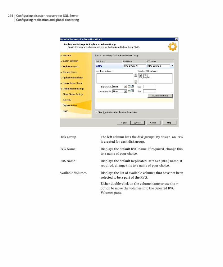
264 Configuring disaster recovery for SQL ServerConfiguring replication and global clustering
Disk Group The left column lists the disk groups. By design, an RVG is created for each disk group.
RVG Name Displays the default RVG name. If required, change this to a name of your choice.
RDS Name Displays the default Replicated Data Set (RDS) name. If required, change this to a name of your choice.
Available Volumes Displays the list of available volumes that have not been selected to be a part of the RVG.
Either double-click on the volume name or use the > option to move the volumes into the Selected RVG Volumes pane.
265Configuring disaster recovery for SQL ServerConfiguring replication and global clustering
■ Click Advanced Settings to specify some additional replication properties. The options on the dialog box are described column-wise, from left to right; refer to the Veritas Volume Replicator
Selected RVG Volumes Displays the list of volumes that have been selected to be a part of the RVG.
To remove a selected volume, either double-click the volume name or use the < option to move the volumes into the Available Volumes pane.
Symantec recommends excluding tempdb from replication. If you earlier moved tempdb to a separate volume in the same disk group as the system database volumes, you can exclude tempdb from replication by removing the tempdb volume from the Selected RVG Volumes pane.
Primary SRL If you did not create a Replicator Log volume on the primary site, click Create New on the drop-down menu. On the New Volume dialog box, specify the name, size, and disk.
Otherwise, select the appropriate primary Replicator Log volume from the drop-down menu and enter an appropriate size.
Secondary SRL If you did not create a Replicator Log volume on the primary site, click Create New on the drop-down menu. On the New Volume dialog box, specify the same name and size as you specified for the primary SRL.
Otherwise, select the appropriate secondary Replicator Log volume from the drop-down menu and enter an appropriate size.
Start Replication after the wizard completes
Select this check box to start replication automatically after the wizard completes the necessary configurations.
Once replication is configured and running, deselecting the checkbox does not stop replication.
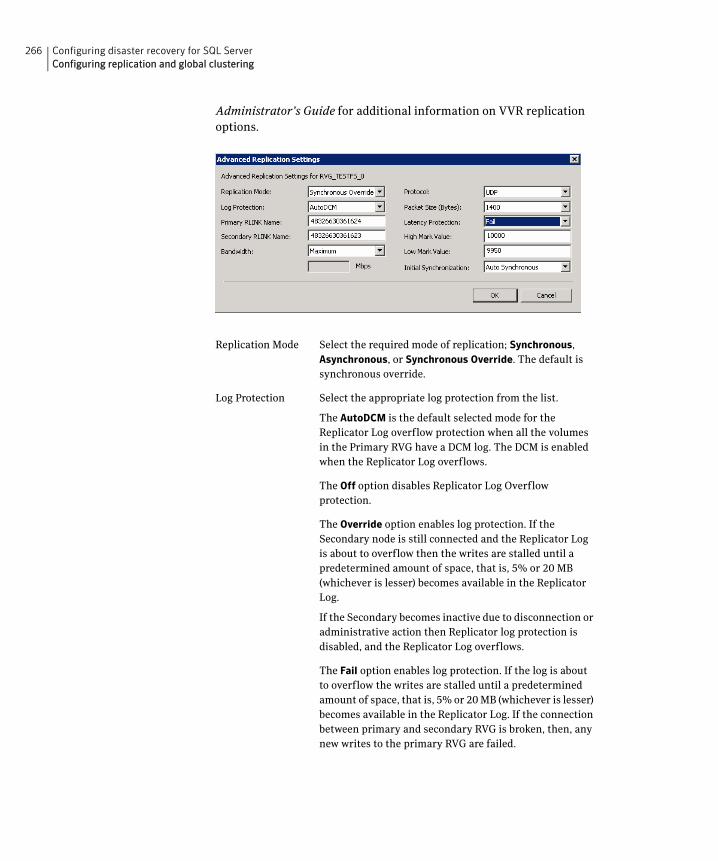
266 Configuring disaster recovery for SQL ServerConfiguring replication and global clustering
Administrator’s Guide for additional information on VVR replication options.
Replication Mode Select the required mode of replication; Synchronous, Asynchronous, or Synchronous Override. The default is synchronous override.
Log Protection Select the appropriate log protection from the list.
The AutoDCM is the default selected mode for the Replicator Log overflow protection when all the volumes in the Primary RVG have a DCM log. The DCM is enabled when the Replicator Log overflows.
The Off option disables Replicator Log Overflow protection.
The Override option enables log protection. If the Secondary node is still connected and the Replicator Log is about to overflow then the writes are stalled until a predetermined amount of space, that is, 5% or 20 MB (whichever is lesser) becomes available in the Replicator Log.
If the Secondary becomes inactive due to disconnection or administrative action then Replicator log protection is disabled, and the Replicator Log overflows.
The Fail option enables log protection. If the log is about to overflow the writes are stalled until a predetermined amount of space, that is, 5% or 20 MB (whichever is lesser) becomes available in the Replicator Log. If the connection between primary and secondary RVG is broken, then, any new writes to the primary RVG are failed.
267Configuring disaster recovery for SQL ServerConfiguring replication and global clustering
Primary RLINK Name
Enter a name of your choice for the primary RLINK. If you do not specify any name then the wizard assigns a default name.
Secondary RLINK Name
Enter a name of your choice for the Secondary RLINK. If you do not specify any name then the wizard assigns a default name.
Bandwidth By default, VVR replication uses the maximum available bandwidth. You can select Specify to specify a bandwidth limit.
The default unit is Mega bits per second (Mbps) and the minimum allowed value is 1 Mbps.
Protocol Choose TCP or UDP. UDP/IP is the default replication protocol.
Packet Size (Bytes) Default is 1400 Bytes. From the drop-down list, choose the required packet size for data transfer. The default unit for the packet size is Bytes. You can set the packet size only if the protocol is UDP/IP.
Latency Protection By default, latency protection is set to Off.
When this option is selected the High Mark Value and the Low Mark Value are disabled. Select the Fail or Override
option to enable Latency protection.
This Override option behaves like the Off option when the Secondary is disconnected and behaves like the Fail option when the Secondary is connected.
High Mark Value This option is enabled only when Latency Protection is set to Override or Fail. It specifies the maximum number of pending updates by which the secondary site can be behind the primary site. The default value is 10000.
To ensure that latency protection is most effective the difference between the high and low mark values must not be very large.
Low Mark Value This option is enabled only when Latency Protection is set to Override or Fail. When the updates in the Replicator log reach the High Mark Value, then the writes to the system at the primary site continues to be stalled until the number of pending updates on the Replicator log falls back to the Low Mark Value. The default is 9950.
268 Configuring disaster recovery for SQL ServerConfiguring replication and global clustering
To apply changes to advanced settings, click OK. On the Replication Settings for Replicated Volume Group panel click Next.
5 In the Replication Attribute Settings panel, specify required replication attribute information for the cluster at the primary and secondary site. Click the arrow icon to expand an RVG row and display the replication attribute fields. If you are configuring an additional secondary site (multiple DR sites), some fields are disabled.
Initial Synchronization
If you are doing an initial setup, then use the Auto
Synchronous option to synchronize the secondary site and start replication. This is the default.
When this option is selected, VVR by default performs intelligent synchronization to replicate only those blocks on a volume that are being used by the file system. If required, you can disable intelligent synchronization.
If you want to use the Synchronize from Checkpoint method then you must first create a checkpoint.
If you have a considerable amount of data on the primary data volumes then you may first want to synchronize the secondary for existing data using the backup-restore method with checkpoint. After the restore is complete, use the Synchronize from Checkpoint option to start replication from the checkpoint to synchronize the secondary with the writes that happened when backup-restore was in progress.
Disk Group Displays the list of disk groups that have been configured.
RVG Name Displays the Replicated Volume Groups corresponding to the disk groups.
IP Address Enter replication IPs that will be used for replication, one for the primary site and another for the secondary site.
Subnet Mask Enter the subnet mask for the system at the primary site and the secondary site.
Public NIC Select the public NIC from the drop-down list for the system at the primary and secondary site.
Copy Enables you to copy the above network settings to any additional RVGs that are listed on this screen. If there is only one RVG, this option does not apply.
269Configuring disaster recovery for SQL ServerConfiguring replication and global clustering
After specifying the replication attributes for each of the RVGs, click Next.
6 In the Global Cluster Settings panel specify the heartbeat information for the wide-area connector resource. You must specify this information for the primary and the secondary cluster. Any existing WAC resource information can be reused. If you are adding a DR site to an existing DR configuration, GCO is already configured at the primary site, so the primary site fields are dimmed.
7 In the Settings Summary panel, review the displayed information. Click Back if you want to change any of the parameters. If you have a printer installed, you can click the printer icon at the bottom of the scrollable list to print the settings.
Click Next to implement the settings.
8 In the Implementation panel, wait till the wizard completes creating the replication configuration and the WAC resource required for global clustering. If a task could not be completed successfully, it is marked with an (x) symbol. For any critical errors, the wizard displays an error message. For less critical errors, the Information column displays a brief description
Use existing settings Allows you to use a WAC resource that already exists at either the primary or secondary site. Click Primary or Secondary, depending on the site at which the WAC resource already exists.
Resource Name Select the existing WAC resource name from the resource name list box.
Create new settings Select the appropriate site, primary or secondary, for which you want to create a new WAC resource.
IP Address Enter a virtual IP for the WAC resource.
Subnet Mask Enter the subnet mask for the system at the primary site and the secondary site.
Public NIC Select the public NIC for each system from the drop-down list for the system at the primary and secondary site.
Start GCO after configuration
Select this check box to bring the cluster service group online and start GCO automatically after the wizard completes the necessary configurations. Otherwise, you must bring the service group online and start GCO manually, after the wizard completes.
Once GCO is configured and running, deselecting the checkbox does not stop GCO.
270 Configuring disaster recovery for SQL ServerConfiguring replication and global clustering
about the task failure and the next screen displays additional information on what action you can take to remedy it. Click Next.
9 In the Finish panel, review the displayed information. If a task did not complete successfully, the panel displays an error message, which will provide some insight into the cause for failure. Click Finish to exit the wizard.
Configuring EMC SRDF replication and global clusteringAfter you complete the service group configuration task in the DR wizard, you configure replication and global clustering.
The wizard helps you to configure the settings for the SRDF resource in the application service group.
Ensure that you have met the prerequisites for replication. See the following topic:
■ “Requirements for EMC SRDF array-based hardware replication” on page 240
In addition, ensure that the Global Cluster Option (GCO) is installed at the primary and secondary site. One static IP address must be available per site for configuring GCO.
The wizard configures the required agent settings as well as the SYMM heartbeat. It uses defaults for optional settings. See the following topic:
■ “Optional settings for EMC SRDF” on page 272
To configure EMC SRDF replication and GCO
1 Verify that you have brought the application service group online at the primary site.
2 If the wizard is still open after the service group cloning task, continue with the Replication Setup panel. Otherwise, launch the wizard and proceed to the Replication Setup panel as follows:
■ Start the DR Configuration Wizard from the Solutions Configuration Center. Click Start > All Programs > Symantec > Veritas Cluster Server > Solutions Configuration Center. Expand the Solutions for Microsoft SQL Server tab and click Disaster Recovery Configuration > Configure Disaster Recovery > Disaster Recovery Configuration Wizard.
■ In the Welcome panel, click Next and continue through the wizard, providing the requested information.
■ In the Replication Methods panel, click Configure EMC SRDF and the Global Cluster Option (GCO). Click Next and continue to the Replication Setup panel.
271Configuring disaster recovery for SQL ServerConfiguring replication and global clustering
3 In the Replication Setup panel, review the replication requirements. If you have met the requirements, click Next.
Warning: Although you can continue with the wizard even if replication requirements are not met, the wizard will warn you that the configuration is not valid. If the configuration is not valid, the SRDF resource cannot come online in the service group.
4 In the SRDF Resource Configuration panel, the wizard populates the required resource fields if replication has been configured. Otherwise, you must enter the required resource settings manually.
5 If you want to configure an additional SRDF resource for the instance, click Add. Otherwise, click Next.
6 In the Global Cluster Settings panel, specify the heartbeat information for the wide-area connector resource. You must specify this information for the primary and the secondary cluster. Any existing WAC resource information can be reused. If you are adding a DR site to an existing DR configuration, GCO is already configured at the primary site, so the primary site fields are dimmed.
Symmetrix Array ID (SID) Specify the array ID for the primary site and for the secondary site.
Device Group name Specify the name of the Symmetrix device group that contains the disks of the disk group for the selected instance.
Available VMDG Resources Select the disk groups associated with the selected application instance.
Use existing settings Allows you to use a WAC resource that already exists at either the primary or secondary site. Click Primary or Secondary, depending on the site at which the WAC resource already exists.
Resource Name Select the existing WAC resource name from the resource name list box.
Create new settings Select the appropriate site, primary or secondary, for which you want to create a new WAC resource.
IP Address Enter a virtual IP for the WAC resource.
Subnet Mask Enter the subnet mask for the system at the primary site and the secondary site.
272 Configuring disaster recovery for SQL ServerConfiguring replication and global clustering
Click Next.
7 In the Settings Summary panel, review the displayed information. Click Back if you want to change any of the parameters specified for the replication resource settings or the global cluster settings.
Click Next.
8 In the Implementation panel, wait until the wizard completes creating the replication configuration and the WAC resource required for global clustering, A check (✔) symbol indicates successful completion of a task. An (x) symbol indicates a task that could not be completed successfully. The Information column shows details about the reasons for task failure. Click Next.
9 In the Finish panel, review the displayed information. If a task did not complete successfully, the panel displays an error message, which will provide some insight into the cause for failure. Click Finish to exit the wizard.
10 Proceed with configuring additional optional settings for the SRDF resource if desired, and then verifying the disaster recovery configuration.
Optional settings for EMC SRDFThe wizard configures the required settings for the SRDF resource in the VCS application service group. The wizard also detects and configures the SymHome attribute.
Other settings are left in the default state. For information on configuring the optional settings, see Veritas Cluster Server Hardware Replication Agent for EMC SRDF, Configuration Guide. If you change any settings, ensure that you edit the resource on both the primary and secondary sites.
Public NIC Select the public NIC for each system from the drop-down list for the system at the primary and secondary site.
Start GCO after configuration
Select this check box to bring the cluster service group online and start GCO automatically after the wizard completes the necessary configurations. Otherwise, you must bring the service group online and start GCO manually, after the wizard completes.
Once GCO is configured and running, deselecting the checkbox does not stop GCO.
273Configuring disaster recovery for SQL ServerConfiguring replication and global clustering
The optional settings use the following defaults:
Configuring Hitachi TrueCopy replication and global clustering After you complete the service group configuration task in the DR wizard, you configure replication and global clustering.
The wizard helps you to configure the settings for the HTC resource in the application service group.
Ensure that you have met the prerequisites. See the following topic:
■ “Requirements for Hitachi TrueCopy array-based hardware replication” on page 242
In addition, ensure that the Global Cluster Option (GCO) is installed at the primary and secondary site. One static IP address must be available per site for configuring GCO.
The wizard configures the required agent settings. It uses defaults for optional settings. See the following topic:
■ “Optional settings for HTC” on page 276
To configure Hitachi TrueCopy replication and GCO
1 Verify that you have brought the application server service group online at the primary site
2 If the wizard is still open after the service group cloning task, continue with the Replication Setup panel. Otherwise, launch the wizard and proceed to the Replication Setup panel as follows:
■ Start the DR Configuration Wizard from the Solutions Configuration Center. Click Start > All Programs > Symantec > Veritas Cluster Server > Solutions Configuration Center. Expand the Solutions for Microsoft SQL Server tab and click Disaster Recovery Configuration > Configure Disaster Recovery > Disaster Recovery Configuration Wizard.
Option Default setting
DevFOTime 2 seconds per device required for a device to fail over
AutoTakeover The default is 1; the agent performs a read-write enable on parti-tioned devices in the write-disabled state during a failover, if devices are consistent.
SplitTakeover The default is 1; the agent brings service groups online on the R2 side even if the devices are in the split state because they are read-write enabled.
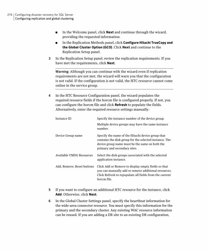
274 Configuring disaster recovery for SQL ServerConfiguring replication and global clustering
■ In the Welcome panel, click Next and continue through the wizard, providing the requested information.
■ In the Replication Methods panel, click Configure Hitachi TrueCopy and the Global Cluster Option (GCO). Click Next and continue to the Replication Setup panel.
3 In the Replication Setup panel, review the replication requirements. If you have met the requirements, click Next.
Warning: Although you can continue with the wizard even if replication requirements are not met, the wizard will warn you that the configuration is not valid. If the configuration is not valid, the HTC resource cannot come online in the service group.
4 In the HTC Resource Configuration panel, the wizard populates the required resource fields if the horcm file is configured properly. If not, you can configure the horcm file and click Refresh to populate the fields. Alternatively, enter the required resource settings manually:
5 If you want to configure an additional HTC resource for the instance, click Add. Otherwise, click Next.
6 In the Global Cluster Settings panel, specify the heartbeat information for the wide-area connector resource. You must specify this information for the primary and the secondary cluster. Any existing WAC resource information can be reused. If you are adding a DR site to an existing DR configuration,
Instance ID Specify the instance number of the device group.
Multiple device groups may have the same instance number.
Device Group name Specify the name of the Hitachi device group that contains the disk group for the selected instance. The device group name must be the same on both the primary and secondary sites.
Available VMDG Resources Select the disk groups associated with the selected application instance.
Add, Remove, Reset buttons Click Add or Remove to display empty fields so that you can manually add or remove additional resources. Click Refresh to repopulate all fields from the current horcm file.
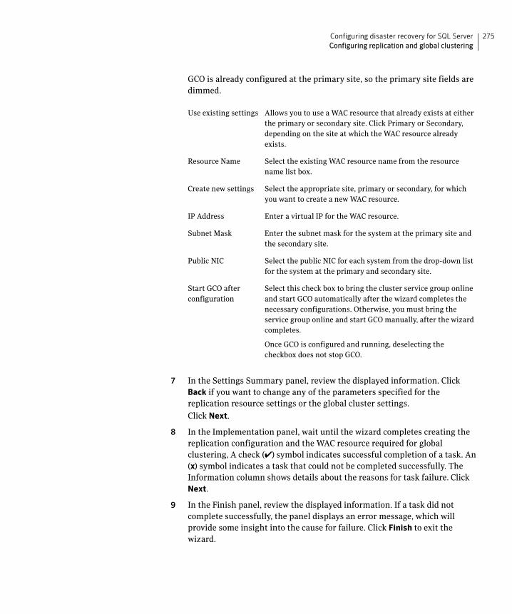
275Configuring disaster recovery for SQL ServerConfiguring replication and global clustering
GCO is already configured at the primary site, so the primary site fields are dimmed.
7 In the Settings Summary panel, review the displayed information. Click Back if you want to change any of the parameters specified for the replication resource settings or the global cluster settings.
Click Next.
8 In the Implementation panel, wait until the wizard completes creating the replication configuration and the WAC resource required for global clustering, A check (✔) symbol indicates successful completion of a task. An (x) symbol indicates a task that could not be completed successfully. The Information column shows details about the reasons for task failure. Click Next.
9 In the Finish panel, review the displayed information. If a task did not complete successfully, the panel displays an error message, which will provide some insight into the cause for failure. Click Finish to exit the wizard.
Use existing settings Allows you to use a WAC resource that already exists at either the primary or secondary site. Click Primary or Secondary, depending on the site at which the WAC resource already exists.
Resource Name Select the existing WAC resource name from the resource name list box.
Create new settings Select the appropriate site, primary or secondary, for which you want to create a new WAC resource.
IP Address Enter a virtual IP for the WAC resource.
Subnet Mask Enter the subnet mask for the system at the primary site and the secondary site.
Public NIC Select the public NIC for each system from the drop-down list for the system at the primary and secondary site.
Start GCO after configuration
Select this check box to bring the cluster service group online and start GCO automatically after the wizard completes the necessary configurations. Otherwise, you must bring the service group online and start GCO manually, after the wizard completes.
Once GCO is configured and running, deselecting the checkbox does not stop GCO.
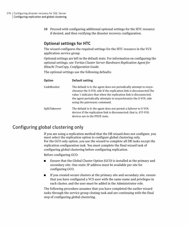
276 Configuring disaster recovery for SQL ServerConfiguring replication and global clustering
10 Proceed with configuring additional optional settings for the HTC resource if desired, and then verifying the disaster recovery configuration.
Optional settings for HTCThe wizard configures the required settings for the HTC resource in the VCS application service group.
Optional settings are left in the default state. For information on configuring the optional settings, see Veritas Cluster Server Hardware Replication Agent for Hitachi TrueCopy, Configuration Guide.
The optional settings use the following defaults:
Configuring global clustering onlyIf you are using a replication method that the DR wizard does not configure, you must select the replication option to configure global clustering only. For the GCO only option, you use the wizard to complete all DR tasks except the replication configuration task. You must complete the final wizard task of configuring global clustering before configuring replication.
Before configuring GCO:
■ Ensure that the Global Cluster Option (GCO) is installed at the primary and secondary site. One static IP address must be available per site for configuring GCO.
■ If you created secure clusters at the primary site and secondary site, ensure that you have configured a VCS user with the same name and privileges in each cluster, and the user must be added in the Administrator role.
The following procedure assumes that you have completed the earlier wizard tasks through the service group cloning task and are continuing with the final step of configuring global clustering.
Option Default setting
LinkMonitor The default is 0; the agent does not periodically attempt to resyn-chronize the S-VOL side if the replication link is disconnected.The value 1 indicates that when the replication link is disconnected, the agent periodically attempts to resynchronize the S-VOL side using the pairresync command.
SplitTakeover The default is 0; the agent does not permit a failover to S-VOL devices if the replication link is disconnected; that is, if P-VOL devices are in the PSUE state.
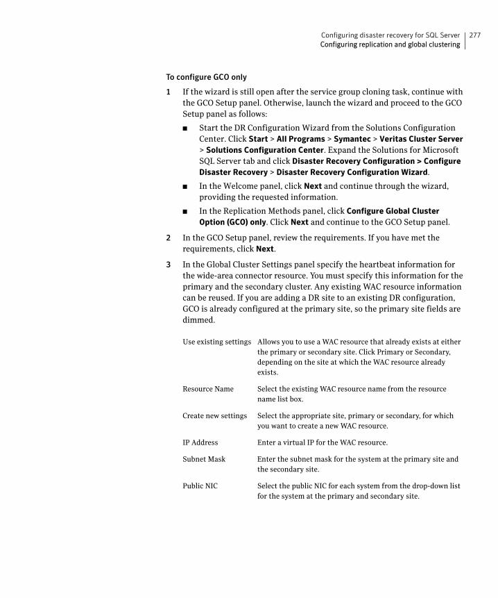
277Configuring disaster recovery for SQL ServerConfiguring replication and global clustering
To configure GCO only
1 If the wizard is still open after the service group cloning task, continue with the GCO Setup panel. Otherwise, launch the wizard and proceed to the GCO Setup panel as follows:
■ Start the DR Configuration Wizard from the Solutions Configuration Center. Click Start > All Programs > Symantec > Veritas Cluster Server > Solutions Configuration Center. Expand the Solutions for Microsoft SQL Server tab and click Disaster Recovery Configuration > Configure Disaster Recovery > Disaster Recovery Configuration Wizard.
■ In the Welcome panel, click Next and continue through the wizard, providing the requested information.
■ In the Replication Methods panel, click Configure Global Cluster Option (GCO) only. Click Next and continue to the GCO Setup panel.
2 In the GCO Setup panel, review the requirements. If you have met the requirements, click Next.
3 In the Global Cluster Settings panel specify the heartbeat information for the wide-area connector resource. You must specify this information for the primary and the secondary cluster. Any existing WAC resource information can be reused. If you are adding a DR site to an existing DR configuration, GCO is already configured at the primary site, so the primary site fields are dimmed.
Use existing settings Allows you to use a WAC resource that already exists at either the primary or secondary site. Click Primary or Secondary, depending on the site at which the WAC resource already exists.
Resource Name Select the existing WAC resource name from the resource name list box.
Create new settings Select the appropriate site, primary or secondary, for which you want to create a new WAC resource.
IP Address Enter a virtual IP for the WAC resource.
Subnet Mask Enter the subnet mask for the system at the primary site and the secondary site.
Public NIC Select the public NIC for each system from the drop-down list for the system at the primary and secondary site.
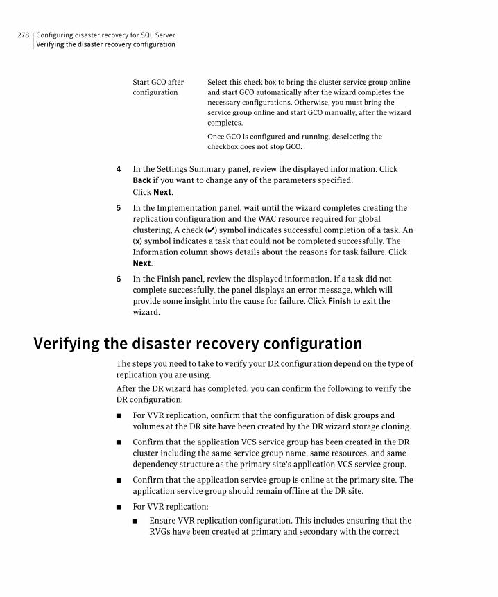
278 Configuring disaster recovery for SQL ServerVerifying the disaster recovery configuration
4 In the Settings Summary panel, review the displayed information. Click Back if you want to change any of the parameters specified.
Click Next.
5 In the Implementation panel, wait until the wizard completes creating the replication configuration and the WAC resource required for global clustering, A check (✔) symbol indicates successful completion of a task. An (x) symbol indicates a task that could not be completed successfully. The Information column shows details about the reasons for task failure. Click Next.
6 In the Finish panel, review the displayed information. If a task did not complete successfully, the panel displays an error message, which will provide some insight into the cause for failure. Click Finish to exit the wizard.
Verifying the disaster recovery configurationThe steps you need to take to verify your DR configuration depend on the type of replication you are using.
After the DR wizard has completed, you can confirm the following to verify the DR configuration:
■ For VVR replication, confirm that the configuration of disk groups and volumes at the DR site have been created by the DR wizard storage cloning.
■ Confirm that the application VCS service group has been created in the DR cluster including the same service group name, same resources, and same dependency structure as the primary site's application VCS service group.
■ Confirm that the application service group is online at the primary site. The application service group should remain offline at the DR site.
■ For VVR replication:
■ Ensure VVR replication configuration. This includes ensuring that the RVGs have been created at primary and secondary with the correct
Start GCO after configuration
Select this check box to bring the cluster service group online and start GCO automatically after the wizard completes the necessary configurations. Otherwise, you must bring the service group online and start GCO manually, after the wizard completes.
Once GCO is configured and running, deselecting the checkbox does not stop GCO.
279Configuring disaster recovery for SQL ServerVerifying the disaster recovery configuration
volume inclusion, replication mode, Replicator Log configuration, and any specified advanced options.
■ Confirm that the replication state matches what was specified during configuration. If specified to start immediately, ensure that it is started. If specified to start later, ensure that it is stopped.
■ Ensure that the VVR RVG VCS service group is configured on the primary and secondary clusters, including the correct dependency to the application service group, the specified IP for replication, and the correct disk group and RVG objects within the RVG VCS service group.
■ Confirm that the RVG service groups are online at the primary and secondary sites.
■ Confirm that the RVG Primary resources are online in the primary cluster's application service group. If they are offline, then bring them online in the primary site's cluster's application service group. Do not bring them online in the secondary site application service group.
■ For array-based replication, verify that the required array resource is created in the primary and secondary cluster’s application service group and that a dependency is set between the VMDg resource and the array resource.
■ For EMC SRDF replication, verify that the SRDF resource is online in the primary cluster’s application service group. If not, bring it online.
■ For Hitachi TrueCopy replication, verify that the HTC resource is online in the primary cluster’s application service group. If not, bring it online.
■ For Hitachi TrueCopy replication, you must perform a manual Volume Manager rescan on all the secondary nodes after setting up replication and other dependent resources, in order to bring the disk groups online. This must be performed only once, after which the failover works uninterrupted. For more information, see Veritas™ Cluster Server Hardware Replication Agent for Hitachi TrueCopy Installation and Configuration Guide.
■ Ensure that the application service groups are configured as global.
■ Check to ensure that the two clusters are communicating and that the status of communication between the two clusters has a state of Alive.
■ If you are using VVR for replication and configuring an additional DR site, verify the heartbeat and replication configuration between all sites.
■ If you are using VVR for replication and chose to start replication manually in the DR wizard, to avoid replicating large amounts of data over the network the first time, then you will need to start the process necessary to synchronize from checkpoint. This typically consists of
■ starting a VVR replication checkpoint
280 Configuring disaster recovery for SQL ServerEstablishing secure communication within the global cluster (optional)
■ performing a block level backup
■ ending the VVR replication checkpoint
■ restoring the block level backup at the DR site
■ starting replication from the VVR replication checkpoint
To learn more about the process of starting replication from a checkpoint, refer to the Veritas Volume Replicator Administrator's Guide.
■ Do not attempt a wide area failover until data has been replicated and the state is consistent and up to date. The Solutions Configuration Center provides a Fire Drill Wizard to test wide area failover for VVR-based replication.
Establishing secure communication within the global cluster (optional)
A global cluster is created in non-secure mode by default. You may continue to allow the global cluster to run in non-secure mode or choose to establish secure communication between clusters.
The following prerequisites are required for establishing secure communication within a global cluster:
■ The clusters within the global cluster must be running in secure mode.
■ You must have Administrator privileges for the domain.
The following information is required for adding secure communication to a global cluster:
■ The active host name or IP address of each cluster in the global configuration.
■ The user name and password of the administrator for each cluster in the configuration.
■ If the local clusters do not point to the same root broker, the host name and port address of each root broker.
Adding secure communication involves the following tasks:
■ Taking the ClusterService-Proc (wac) resource in the ClusterService group offline on the clusters in the global environment.
■ Adding the -secure option to the StartProgram attribute on each node.
■ Establishing trust between root brokers if the local clusters do not point to the same root broker.

281Configuring disaster recovery for SQL ServerEstablishing secure communication within the global cluster (optional)
■ Bringing the ClusterService-Proc (wac) resource online on the clusters in the global cluster.
To take the ClusterService-Proc (wac) resource offline on all clusters
1 From Cluster Monitor, log on to a cluster in the global cluster.
2 In the Service Groups tab of the Cluster Explorer configuration tree, expand the ClusterService group and the Process agent.
3 Right-click the ClusterService-Proc resource, click Offline, and click the appropriate system from the menu.
4 Repeat step 1 to step 3 for the additional clusters in the global cluster.
To add the -secure option to the StartProgram resource
1 In the Service Groups tab of the Cluster Explorer configuration tree, right-click the ClusterService-Proc resource under the Process type in the ClusterService group.
2 Click View, and then Properties view.
3 Click the Edit icon to edit the StartProgram attribute.
4 In the Edit Attribute dialog box, add -secure switch to the path of the executable Scalar Value.
For example:
“C:\Program Files\Veritas\Cluster Server\bin\wac.exe” -secure
5 Repeat step 4 for each system in the cluster.
6 Click OK to close the Edit Attribute dialog box.
7 Click the Save and Close Configuration icon in the tool bar.
8 Repeat step 1 to step 7 for each cluster in the global cluster.
To establish trust between root brokers if there is more than one root broker
◆ Establishing trust between root brokers is only required if the local clusters do not point to the same root broker.
Log on to the root broker for each cluster and set up trust to the other root brokers in the global cluster. The complete syntax of the command is:
vssat setuptrust --broker <host:port> --securitylevel
<low|medium|high> [--hashfile <filename> | --hash <root
hash in hex>]
For example, to establish trust with a low security level in a global cluster comprised of Cluster1 pointing to RB1 and Cluster2 pointing to RB2:
from RB1, type:
282 Configuring disaster recovery for SQL ServerAdding multiple DR sites (optional)
vssat setuptrust --broker RB2:14141 --securitylevel low
from RB2, type:
vssat setuptrust --broker RB1:14141 --securitylevel low
To bring the ClusterService-Proc (wac) resource online on all clusters
1 In the Service Groups tab of the Cluster Explorer configuration tree, expand the ClusterService group and the Process agent.
2 Right-click the ClusterService-Proc resource, click Online, and click the appropriate system from the menu.
3 Repeat step 1 and step 2 for the additional clusters in the global cluster.
Adding multiple DR sites (optional)In a Veritas Volume Replicator replication environment only, you can use the DR wizard to add additional secondary DR sites. Veritas Cluster Server supports up to four DR sites. In other replication environments, additional DR sites require manual configuration.
Run the DR wizard and on the Secondary System selection panel, select the new site.
Before you start the wizard on the task of configuring replication and global clustering, ensure that the cluster service group is online at the existing primary and secondary sites. This enables the wizard to configure GCO not only between the selected primary site and the new secondary site but also between the new site and the earlier configured secondary site. Otherwise, the wizard displays a warning message after the global clustering task.
When configuring the VVR replication settings with the wizard for the additional site, fields that must match existing settings are dimmed so that you cannot change them. For example, you cannot change the RVG name or RVG layout on the Replication Settings panel. Similarly, on the Global Cluster Settings panel, GCO has already been configured at the primary site, so the primary site fields are dimmed.
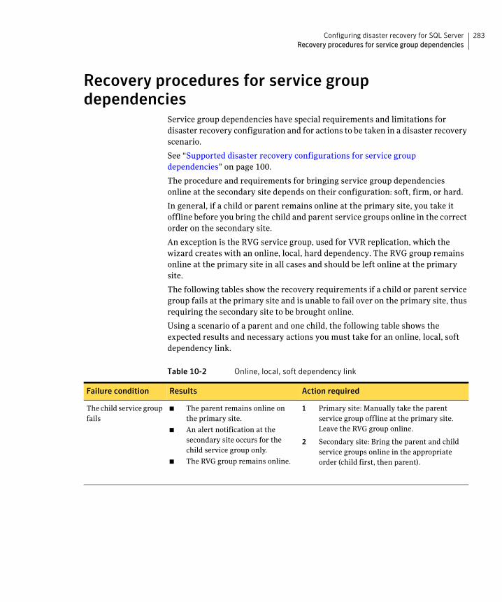
283Configuring disaster recovery for SQL ServerRecovery procedures for service group dependencies
Recovery procedures for service group dependencies
Service group dependencies have special requirements and limitations for disaster recovery configuration and for actions to be taken in a disaster recovery scenario.
See “Supported disaster recovery configurations for service group dependencies” on page 100.
The procedure and requirements for bringing service group dependencies online at the secondary site depends on their configuration: soft, firm, or hard.
In general, if a child or parent remains online at the primary site, you take it offline before you bring the child and parent service groups online in the correct order on the secondary site.
An exception is the RVG service group, used for VVR replication, which the wizard creates with an online, local, hard dependency. The RVG group remains online at the primary site in all cases and should be left online at the primary site.
The following tables show the recovery requirements if a child or parent service group fails at the primary site and is unable to fail over on the primary site, thus requiring the secondary site to be brought online.
Using a scenario of a parent and one child, the following table shows the expected results and necessary actions you must take for an online, local, soft dependency link.
Table 10-2 Online, local, soft dependency link
Failure condition Results Action required
The child service group fails
■ The parent remains online on the primary site.
■ An alert notification at the secondary site occurs for the child service group only.
■ The RVG group remains online.
1 Primary site: Manually take the parent service group offline at the primary site. Leave the RVG group online.
2 Secondary site: Bring the parent and child service groups online in the appropriate order (child first, then parent).
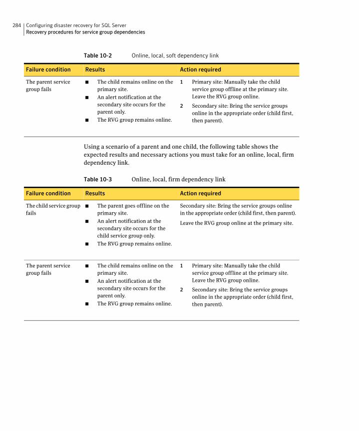
284 Configuring disaster recovery for SQL ServerRecovery procedures for service group dependencies
Using a scenario of a parent and one child, the following table shows the expected results and necessary actions you must take for an online, local, firm dependency link.
The parent service group fails
■ The child remains online on the primary site.
■ An alert notification at the secondary site occurs for the parent only.
■ The RVG group remains online.
1 Primary site: Manually take the child service group offline at the primary site. Leave the RVG group online.
2 Secondary site: Bring the service groups online in the appropriate order (child first, then parent).
Table 10-3 Online, local, firm dependency link
Failure condition Results Action required
The child service group fails
■ The parent goes offline on the primary site.
■ An alert notification at the secondary site occurs for the child service group only.
■ The RVG group remains online.
Secondary site: Bring the service groups online in the appropriate order (child first, then parent).
Leave the RVG group online at the primary site.
The parent service group fails
■ The child remains online on the primary site.
■ An alert notification at the secondary site occurs for the parent only.
■ The RVG group remains online.
1 Primary site: Manually take the child service group offline at the primary site. Leave the RVG group online.
2 Secondary site: Bring the service groups online in the appropriate order (child first, then parent).
Table 10-2 Online, local, soft dependency link
Failure condition Results Action required
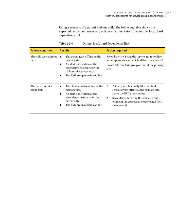
285Configuring disaster recovery for SQL ServerRecovery procedures for service group dependencies
Using a scenario of a parent and one child, the following table shows the expected results and necessary actions you must take for an online, local, hard dependency link.
Table 10-4 Online, local, hard dependency link
Failure condition Results Action required
The child service group fails
■ The parent goes offline on the primary site.
■ An alert notification at the secondary site occurs for the child service group only.
■ The RVG group remains online.
Secondary site: Bring the service groups online in the appropriate order (child first, then parent).
Do not take the RVG group offline at the primary site.
The parent service group fails
■ The child remains online on the primary site.
■ An alert notification at the secondary site occurs for the parent only.
■ The RVG group remains online.
1 Primary site: Manually take the child service group offline at the primary site. Leave the RVG group online.
2 Secondary site: Bring the service groups online in the appropriate order (child first, then parent).

286 Configuring disaster recovery for SQL ServerRecovery procedures for service group dependencies
Chapter
11Testing fault readiness by running a fire drill
Topics in this chapter include:
■ About disaster recovery fire drills
■ About the Fire Drill Wizard
■ About post-fire drill scripts
■ Tasks for configuring and running fire drills
■ Prerequisites for a fire drill
■ Preparing the fire drill configuration
■ Running a fire drill
■ Recreating a fire drill configuration that has changed
■ Restoring the fire drill system to a prepared state
■ Deleting the fire drill configuration
About disaster recovery fire drillsA disaster recovery plan should include regular testing of an environment to ensure that a DR solution is effective and ready should disaster strike. This testing is called a fire drill.
A fire drill is performed at the secondary site using a special service group for fire drills. The fire drill service group uses a copy of the data that is used by the application service group.
288 Testing fault readiness by running a fire drillAbout the Fire Drill Wizard
About the Fire Drill WizardVeritas Storage Foundation HA for Windows (SFW HA) provides a Fire Drill Wizard to help you set up and run a fire drill on a disaster recovery environment. You launch the Fire Drill Wizard from the Solutions Configuration Center.
The Fire Drill Wizard tests the fault readiness of a disaster recovery configuration by mimicking a failover from the primary site to the secondary site. The wizard does this without stopping the application at the primary site and disrupting user access.
The Fire Drill Wizard supports conducting a fire drill for a disaster recovery site that uses Veritas Volume Replicator (VVR) or that uses Hitachi TrueCopy or EMC SRDF hardware replication.
About Fire Drill Wizard general operationsThe Fire Drill Wizard performs the following operations:
■ Prepares for the fire drill by creating a fire drill service group on the secondary site
The fire drill service group is a copy of the application service group. When creating the fire drill service group, the wizard uses the application service group name, with the suffix _fd. The wizard renames the fire drill service group resources by adding a prefix FDnn and changes attribute values as necessary to refer to the FD resources.
The wizard also supports fire drill service groups created under a different naming convention by an earlier version of the wizard.
■ Runs the fire drill by bringing the fire drill service group online on the secondary site
This operation demonstrates the ability of the application service group to failover and come online at the secondary site should the need arise.
Fire drill service groups do not interact with outside clients or with other instances of resources, so they can safely come online even when the application service group is online on the primary site.
■ Restores the fire drill configuration, taking the fire drill service group offline
After you complete the fire drill, you run the wizard to restore the fire drill configuration to a prepared state. Otherwise, the fire drill service group remains online. If you run a fire drill on one service group, restore that service group before you continue with a fire drill on another service group.
You must also restore the fire drill configuration before you can delete it.
289Testing fault readiness by running a fire drillAbout the Fire Drill Wizard
Warning: If the fire drill service group remains online, it could cause failures in your environment. For example, if the application service group were to fail over to the node hosting the fire drill service group, there would be resource conflicts, resulting in both service groups faulting. Therefore, always use the wizard to restore the fire drill configuration to a prepared state as soon as possible after completing the fire drill testing for a service group.See “Restoring the fire drill system to a prepared state” on page 309.
■ Deletes the fire drill configuration
The details of some Fire Drill Wizard operations are different depending on the replication environment.
See “About Fire Drill Wizard operations in a VVR environment” on page 289.
See “About Fire Drill Wizard operations in a Hitachi TrueCopy or EMC SRDF environment” on page 290.
About Fire Drill Wizard operations in a VVR environmentThe general operations of the Fire Drill Wizard are the same in all replication environments.
■ Prepares for the fire drill, creating a fire drill service group on the secondary site
■ Runs the fire drill, bringing the fire drill service group online on the secondary site
■ Restores the fire drill configuration, taking the fire drill service group offline
■ Deletes the fire drill configuration
See “About the Fire Drill Wizard” on page 288.
However, the following additional Fire Drill Wizard operations are specific to a Veritas Volume Replicator (VVR) environment.
Preparing the fire drill configurationIn a VVR environment, when preparing the fire drill configuration, the wizard does the following:
■ In the fire drill service group, replaces the RVGPrimary resources with VMDg resources
■ Uses the SFW HA VxSnap feature to prepare snapshot mirrors for use during the fire drill
290 Testing fault readiness by running a fire drillAbout the Fire Drill Wizard
You assign one or more disks for the mirrored volumes while running the wizard. Mirror preparation can take some time, so you can exit the wizard once this step is started and let the preparation continue in the background.
Running the fire drill In a VVR environment, when running the fire drill, the wizard does the following:
■ Detaches the mirrors from the original volumes to create point-in-time snapshots of the production data
■ Creates a fire drill disk group on the secondary site with a snapshot of the application data to use for testing purposes
Restoring the fire drill configurationIn a VVR environment, when restoring the fire drill system to a prepared state, the wizard does the following:
■ Takes the fire drill service group offline
■ Disables the fire drill service group resources
■ Imports the fire drill disk group
■ Joins the fire drill disk group to the application service group disk group
■ Snaps back the snapshot mirrors to reattach to the original volumes
Deleting the fire drill configurationIn a VVR environment, when deleting the fire drill configuration, the wizard does the following:
■ Deletes the fire drill service group and any associated registry entry
■ Performs the snap abort operation on the snapshot mirrors to free up the disk space
About Fire Drill Wizard operations in a Hitachi TrueCopy or EMC SRDF environment
The general operations of the Fire Drill Wizard are the same in all replication environments.
■ Prepares for the fire drill, creating a fire drill service group on the secondary site
■ Runs the fire drill, bringing the fire drill service group online on the secondary site
291Testing fault readiness by running a fire drillAbout the Fire Drill Wizard
■ Restores the fire drill configuration, taking the fire drill service group offline
■ Deletes the fire drill configuration
See “About the Fire Drill Wizard” on page 288.
However, additional Fire Drill Wizard operations are specific to a Hitachi TrueCopy or EMC SRDF replication environment.
In a Hitachi TrueCopy or EMC SRDF replication environment, the wizard performs the following additional actions during preparation, running of the fire drill, restoring the configuration, and deleting the configuration. You must configure the ShadowImage (for Hitachi) or BCV (for SRDF) pairs before running the wizard.
Preparing the fire drill configurationWhen preparing the fire drill configuration, the wizard does the following:
■ In the fire drill service group, the wizard creates HTCSnap or SRDFSnap resources for each HTC and SRDF resource in the application service group. The SRDFSnap and HTCSnap resources from the firedrill service group are linked to the respective resources configured in the main application service group.
■ The wizard configures the Snap resource. The following Snap resource attributes are set to a value of 1:
■ UseSnapshot (take a local snapshot of the target array)
■ RequireSnapshot (require a successful snapshot for the Snap resource to come online)
■ MountSnapshot (use the snapshot to bring the fire drill service group online
Running the fire drill When running the fire drill, the wizard brings the HTCSnap or SRDFSnap agent online. The HTCSnap or SRDFSnap agent manage the replication and mirroring functionality according to the attribute settings. The Snap agents take a consistent snapshot of the replicating data using the mirroring technology provided by the array vendor. The Snap agents also import the disk group present on the snapshot devices with a different name.
In more detail, the Snap agent does the following:
■ Suspends replication to get a consistent snapshot
■ For HTCSnap, takes a snapshot of the replicating application data on a ShadowImage device
292 Testing fault readiness by running a fire drillAbout post-fire drill scripts
■ For SRDFSnap, takes a snapshot of the replicating application data on a BCV device
■ Resumes replication
■ Modifies the disk group name in the snapshot
Restoring the fire drill configurationWhen restoring the fire drill configuration to a prepared state, the wizard does the following:
■ Takes the fire drill service group offline, thus also taking offline the SRDF and HTC Snap agents
This action reattaches the hardware mirrors to the replicating secondary devices and resynchronizes them.
Deleting the fire drill configurationWhen deleting the fire drill configuration, the wizard does the following:
■ Deletes the fire drill service group
■ Deletes any associated registry entry
If you want to remove the hardware mirrors, you must do so manually.
For more information about the Hitachi TrueCopy Snap agent functions, see Veritas Cluster Server Hardware Replication Agent for Hitachi TrueCopy, Configuration Guide.
For more information about the EMC SRDF Snap agent functions, see Veritas Cluster Server Hardware Replication Agent for EMC SRDF, Configuration Guide.
About post-fire drill scriptsYou can specify a script for the Fire Drill Wizard to run on the secondary site at the end of the fire drill.
For example, in a SQL Server environment, if you create and populate a test table at the primary site, you could create a script to verify replication of the data.
For the wizard to run the script, the script must exist on the secondary system that you are specifying for the fire drill.
Note: The wizard does not support using script commands to launch a user interface window. In such a case, the process is created but the UI window does not display.

293Testing fault readiness by running a fire drillAbout post-fire drill scripts
Optionally, you can specify to run a Windows PowerShell cmdlet by creating a .bat file.
To run a cmdlet, create a .bat file with the following entry:
%windir%\system32\WindowsPowerShell\v1.0\PowerShell.exe -command "$ScriptName"
Where
$ScriptName = .ps1 script (fully qualified) / cmdlet entered by user.
For example:
D:\WINDOWS\system32\WindowsPowerShell\v1.0\PowerShell.exe -command C:\myTest.ps1
Specify the name of the .bat file as the script to run.
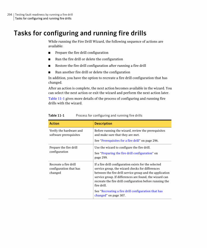
294 Testing fault readiness by running a fire drillTasks for configuring and running fire drills
Tasks for configuring and running fire drillsWhile running the Fire Drill Wizard, the following sequence of actions are available:
■ Prepare the fire drill configuration
■ Run the fire drill or delete the configuration
■ Restore the fire drill configuration after running a fire drill
■ Run another fire drill or delete the configuration
In addition, you have the option to recreate a fire drill configuration that has changed.
After an action is complete, the next action becomes available in the wizard. You can select the next action or exit the wizard and perform the next action later.
Table 11-1 gives more details of the process of configuring and running fire drills with the wizard.
Table 11-1 Process for configuring and running fire drills
Action Description
Verify the hardware and software prerequisites
Before running the wizard, review the prerequisites and make sure that they are met.
See “Prerequisites for a fire drill” on page 296.
Prepare the fire drill configuration
Use the wizard to configure the fire drill.
See “Preparing the fire drill configuration” on page 299.
Recreate a fire drill configuration that has changed
If a fire drill configuration exists for the selected service group, the wizard checks for differences between the fire drill service group and the application service group. If differences are found, the wizard can recreate the fire drill configuration before running the fire drill.
See “Recreating a fire drill configuration that has changed” on page 307.
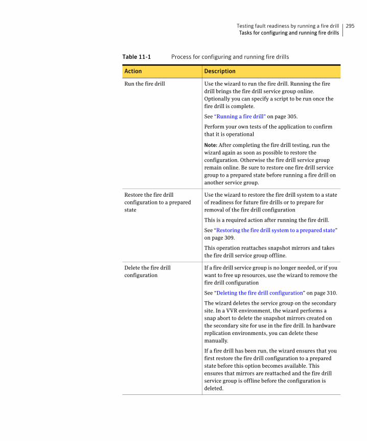
295Testing fault readiness by running a fire drillTasks for configuring and running fire drills
Run the fire drill Use the wizard to run the fire drill. Running the fire drill brings the fire drill service group online. Optionally you can specify a script to be run once the fire drill is complete.
See “Running a fire drill” on page 305.
Perform your own tests of the application to confirm that it is operational
Note: After completing the fire drill testing, run the wizard again as soon as possible to restore the configuration. Otherwise the fire drill service group remain online. Be sure to restore one fire drill service group to a prepared state before running a fire drill on another service group.
Restore the fire drill configuration to a prepared state
Use the wizard to restore the fire drill system to a state of readiness for future fire drills or to prepare for removal of the fire drill configuration
This is a required action after running the fire drill.
See “Restoring the fire drill system to a prepared state” on page 309.
This operation reattaches snapshot mirrors and takes the fire drill service group offline.
Delete the fire drill configuration
If a fire drill service group is no longer needed, or if you want to free up resources, use the wizard to remove the fire drill configuration
See “Deleting the fire drill configuration” on page 310.
The wizard deletes the service group on the secondary site. In a VVR environment, the wizard performs a snap abort to delete the snapshot mirrors created on the secondary site for use in the fire drill. In hardware replication environments, you can delete these manually.
If a fire drill has been run, the wizard ensures that you first restore the fire drill configuration to a prepared state before this option becomes available. This ensures that mirrors are reattached and the fire drill service group is offline before the configuration is deleted.
Table 11-1 Process for configuring and running fire drills
Action Description
296 Testing fault readiness by running a fire drillPrerequisites for a fire drill
Prerequisites for a fire drillBefore running the Fire Drill Wizard make sure that you meet the following general requirements:
■ You can run the Fire Drill Wizard from any node in the domain of the cluster, as long as the SFW HA client is installed on that node.
■ If the cluster is secured, the login you use to run the Fire Drill Wizard must have the appropriate permissions to make changes in the cluster.
■ If a firewall exists between the wizard and any systems it needs access to, the firewall must be set to allow both ingoing and outgoing TCP requests on port 7419.
■ For each IP address in the application service group, an IP address must be available to use on the secondary site for the fire drill service group.
The wizard can accept input for one IP address and Lanman resource. If the application service group has multiple IP addresses and Lanman resources, the wizard notifies you to edit the fire drill service group resources to supply these values. Information on editing service group resources is covered in the VCS administration guide.
See Veritas Cluster Server Administrator’s Guide.
■ If you want the fire drill wizard to run a script that you supply, ensure that the script file is available on any secondary site nodes where you plan to run the fire drill.
For testing purposes, you may want to create and populate a new table from the active node at the primary site. After you run the fire drill to bring the fire drill service group online and create the fire drill snapshots, you can check that the table and its data were replicated and are available from the fire drill service group. You can automate this process with a script and when preparing to run the fire drill, specify it as a post-fire drill script.
Additional requirements apply to specific replication environments.
See “Prerequisites for a fire drill in a VVR environment” on page 296.
See “Prerequisites for a fire drill in a Hitachi TrueCopy environment” on page 297.
See “Prerequisites for a fire drill in an EMC SRDF environment” on page 298.
Prerequisites for a fire drill in a VVR environmentBefore you run the Fire Drill Wizard make sure that you meet both the general requirements and the specific requirements for your replication environment.
General requirements are covered separately.
297Testing fault readiness by running a fire drillPrerequisites for a fire drill
See “Prerequisites for a fire drill” on page 296.
Make sure that the following additional prerequisites are met before configuring and running a fire drill in a Veritas Volume Replicator (VVR) environment:
■ The primary and secondary sites must be fully configured with VVR replication and the global cluster option.
■ The Veritas FlashSnap option must be installed on all nodes of the secondary site cluster.
■ The secondary system where you plan to run the fire drill must have access to the replicated volumes.
■ On the secondary site, empty disks must be available with enough disk space to create snapshot mirrors of the volumes. Snapshot mirrors take up the same amount of space as the original volumes. In addition, two disk change object (DCO) volumes are created for each snapshot mirror, one for the source volume and one for the snapshot volume. The two DCO volumes must be on different disks. Allow 2 MB additional space for each DCO volume.
The empty disks must be in the same disk group that contains the RVG. If the disk group does not have empty disks available, you must use the VEA to add the disks to the disk group before you run the wizard. The secondary system must have access to the disks or LUNs.
■ All disk groups in the service group must be configured for replication. The Fire Drill wizard does not support a VVR configuration in which disk groups are excluded from replication. However, you can exclude individual volumes within a disk group from replication.
Prerequisites for a fire drill in a Hitachi TrueCopy environmentBefore you run the Fire Drill Wizard make sure that you meet both the general requirements and the specific requirements for your replication environment.
General requirements are covered separately.
See “Prerequisites for a fire drill” on page 296.
Make sure that the following prerequisites are met before configuring and running a fire drill in a Hitachi TrueCopy environment:
■ The primary and secondary sites must be fully configured with Hitachi TrueCopy replication and the global cluster option. The configuration must follow the applicable instructions in the Veritas Storage Foundation HA for Windows documentation for configuring disaster recovery with Hitachi TrueCopy.
298 Testing fault readiness by running a fire drillPrerequisites for a fire drill
■ The secondary system where you plan to run the fire drill must have access to the replicated volumes.
■ Make sure that Hitachi RAID Manager/Command Control Interface (CCI) is installed.
■ ShadowImage for TrueCopy must be installed and configured for each LUN on the secondary site target array. ShadowImage pairs must be created to allow for mirroring at the secondary site.
■ The name of the ShadowImage device group must be the same as the replicated device group for both replicated and non-replicated LUNs that are to be snapshot. The instance number should be different.
■ Make sure the HORCM instance managing the S-VOLs runs continuously; the agent does not start this instance.
Prerequisites for a fire drill in an EMC SRDF environmentBefore you run the Fire Drill Wizard make sure that you meet both the general requirements and the specific requirements for your replication environment.
General requirements are covered separately.
See “Prerequisites for a fire drill” on page 296.
Make sure that the following prerequisites are met before configuring and running a fire drill in an EMC SRDF environment:
■ The primary and secondary sites must be fully configured with EMC SRDF replication and the global cluster option. The configuration must follow the applicable instructions in the Veritas Storage Foundation HA for Windows documentation for configuring disaster recovery with EMC SRDF.
■ The secondary system where you plan to run the fire drill must have access to the replicated volumes.
■ The infrastructure to take snapshots at the secondary site must be properly configured between the secondary site source and target arrays. This process involves associating Symmetric Business Continuance Volumes (BCVs) and synchronizing them with the secondary site source.
■ If you plan to run a fire drill on SRDF/A devices, you must have a TimeFinder/CG license. Make sure TimeFinder for SRDF is installed and configured at the target array.
■ To take snapshots of R2 devices, BCVs must be associated with the RDF2 device group and fully established with the devices.
■ To take snapshots of non-replicated devices, create a EMC Symmetrix device group with the same name as the SFW disk group. The device group
299Testing fault readiness by running a fire drillPreparing the fire drill configuration
must contain the same devices as in the disk group and have the corresponding BCVs associated.
Preparing the fire drill configurationPreparing the fire drill configuration creates a fire drill service group. You specify the application service group and the secondary system to use. Only one service group can be prepared for a fire drill at one time.
For a Veritas Volume Replicator (VVR) environment, the preparation step also prepares snapshot mirrors of production data at the specified node on the secondary site.
Note: Preparing the snapshot mirrors takes some time to complete.
Before you prepare the fire drill configuration with the Fire Drill Wizard, make sure that you meet the prerequisites.
See “Prerequisites for a fire drill” on page 296.
To prepare the fire drill configuration
1 Open the Solutions Configuration Center (Start > All Programs > Symantec > Veritas Cluster Server > Solutions Configuration Center).
2 Start the Fire Drill Wizard (expand Solutions for Microsoft SQL, expand Fire Drill, expand Configure or run a fire drill, and click Fire Drill Wizard).
3 In the Welcome panel, review the information and click Next.
4 In the System Selection panel, specify a system in the primary site cluster and click Next.
See “System Selection panel details” on page 301.
5 In the Service Group Selection panel, select the service group that you want to use for the fire drill and click Next.
See “Service Group Selection panel details” on page 301.
6 In the Secondary System Selection panel, select the cluster and the system to be used for the fire drill at the secondary site, and then click Next.
See “Secondary System Selection panel details” on page 301.
7 If the Fire Drill Prerequisites panel is displayed, review the information and ensure that all prerequisites are met. Click Next.
See “Prerequisites for a fire drill” on page 296.
300 Testing fault readiness by running a fire drillPreparing the fire drill configuration
Otherwise, if a fire drill service group already exists on this system for the specified service group, one of the following panels is displayed:
8 If the Fire Drill Service Group Settings panel is displayed, assign the virtual IP address and virtual name (Lanman name) to be used for the fire drill service group that will be created on the secondary site.
See “Fire Drill Service Group Settings panel details” on page 302.
9 The wizard selects the appropriate panel to display next, depending on the replication method. Fill in any required information on the panel that is displayed.
If the Run Fire Drill option or Delete Fire Drill options are shown, a fire drill service group has already been prepared.
You can run the fire drill with no further preparation. Click Run Fire Drill and follow the procedure for running a fire drill.
See “Running a fire drill” on page 305.
If the Fire Drill Restoration panel is displayed, the fire drill service group remains online from a previous fire drill.
Follow the procedure for restoring the fire drill configuration to a prepared state. This must be done before running a new fire drill.
See “Restoring the fire drill system to a prepared state” on page 309.
If the Recreate Fire Drill Service Group panel is displayed, a fire drill service group has already been prepared but is not up to date.
You can choose to recreate the fire drill configuration to bring it up to date.
See “Recreating a fire drill configuration that has changed” on page 307.
Or you can clear the check box to recreate the configuration and run the fire drill on the existing configuration.
VVR replication Disk Selection panel
See “Disk Selection panel details” on page 302.
Hitachi TrueCopy replication
Horcm Files Path Selection panel
See “Hitachi TrueCopy Path Information panel details” on page 303.
HTCSnap Resource Configuration panel
See “HTCSnap Resource Configuration panel details” on page 303.
301Testing fault readiness by running a fire drillPreparing the fire drill configuration
Click Next.
10 In the Fire Drill Preparation panel, the wizard shows the status of the preparation tasks.
See “Fire Drill Preparation panel details” on page 304.
When preparation is complete, click Next.
11 The Summary panel displays the message that preparation is complete.
To run the fire drill now, click Next. Continue with the procedure to run the fire drill.
See “Running a fire drill” on page 305.
To run the fire drill later, click Finish. The fire drill preparation remains in place.
System Selection panel detailsUse the System Selection panel of the wizard to specify a system in the primary site cluster.
All systems containing online global service groups are available to select. The default system is the node where you launched the wizard (localhost) if a global service group is online on that system. When selecting a system you can specify either a fully qualified host name or IP address.
Service Group Selection panel detailsUse the Service Group Selection panel of the wizard to select the service group that you want to use for the fire drill. You can select only one service group at a time for a fire drill.
Secondary System Selection panel detailsUse the Secondary System Selection panel of the wizard to select the cluster and the system to be used for the fire drill at the secondary site.
The selected system must have access to the replicated data.
The system must have access to disks for the snapshots that will be created for the fire drill.
EMC SRDF replication
SRDFSnap Resource Configuration panel
See “SRDFSnap Resource Configuration panel details” on page 304.
302 Testing fault readiness by running a fire drillPreparing the fire drill configuration
Fire Drill Service Group Settings panel detailsUse the Fire Drill Service Group Settings panel of the wizard to assign the virtual IP address and virtual name (Lanman name) to be used for the fire drill service group that will be created on the secondary site. These must be an address and name not currently in use.
If the service group contains more than one IP and Lanman resource, this panel does not display. After the fire drill service group is created, the wizard notifies you to manually update the IP and Lanman resources in the fire drill service group.
Disk Selection panel detailsDuring fire drill preparation in a VVR replication environment, you must ensure that information is available to the wizard for creating the fire drill snapshots. Use the Disk Selection panel of the wizard to review the information on disks and volumes and make the selections for the fire drill snapshots, as follows:
Volume Select the volumes for the fire drill snapshots. By default all volumes associated with the service group are selected. If you deselect a volume that might result in the fire drill service group failing to come online, the wizard displays a warning message.
Note: The Disk Selection panel also appears if the wizard is recreating a fire drill service group to which volumes have been added. In that case, only the new volumes are shown for selection.
Disk Group Shows the name of the disk group that contains the original volumes. This field is display only.
303Testing fault readiness by running a fire drillPreparing the fire drill configuration
Hitachi TrueCopy Path Information panel detailsDuring fire drill preparation in a Hitachi TrueCopy replication environment, the Hitachi TrueCopy Path Information panel is displayed.
The wizard populates the path field with the customary default location:
C:\Windows
where C is the system drive.
If the horcm configuration files are in a different location, edit the field to specify that location.
HTCSnap Resource Configuration panel detailsDuring fire drill preparation in a Hitachi TrueCopy replication environment, the wizard discovers the HTC resources and non-replicating SFW disk groups in the application service group
This information is used to configure the HTCSnap resources.
The wizard lists each HTCSnap resource that will be configured. You can clear the HTCSnap resource name check box if you do not want to include its dependent disk groups in the fire drill.
You must specify the ShadowImage instance.
Fire Drill DG Shows the name of the fire drill disk group that running the fire drill will create on the secondary system to contain the snapshots. This field is display only. For the fire drill disk group name, the wizard prefixes the original disk group name with FDnn.
Disk Click the plus icon to the right of the Disk column and specify the disk to be used for the snapshot volume. Repeat for each row that contains a selected volume.
You can store multiple snapshot volumes on the same disk, if the production volumes reside on disks in the same disk group.
If there is not enough disk space, you can use the Veritas Enterprise Administrator to add disks to the disk group. Then click the Refresh button in the wizard.
Mount Details Shows the mount details for the snapshot volumes on the secondary system, which match the mounts for the production volumes. This field is display only.
304 Testing fault readiness by running a fire drillPreparing the fire drill configuration
The HTCSnap Resource Configuration panel shows the following:
More information about HTCSnap resource configuration and operation is available.
See “About Fire Drill Wizard operations in a Hitachi TrueCopy or EMC SRDF environment” on page 290.
SRDFSnap Resource Configuration panel detailsDuring fire drill preparation in an EMC SRDF replication environment, the wizard validates whether at least one BCV device is attached to every device (RDF2) of the SRDF device group. If not, the wizard displays an informational message on this panel. The panel shows as the Target Resource Name the name of the resource that is managing the LUNs that you want to snapshot. For data being replicated from the primary site, the Target Resource Name is the name of the SRDF resource. For data that is not replicated, the Target Resource Name is the name of the disk group resource.
For example, in a typical Microsoft SQL Server setup, you might replicate data files and logs, but you may choose to avoid replicating temporary tempdb. The tempdb must still exist at the DR site and may be part of its own disk group.
The wizard lists each SRDFSnap resource that will be configured. You can clear the SRDFSnap resource name check box if you do not want to include its dependent disk groups in the fire drill.
More information about SRDFSnap resource configuration and operation is available.
See “About Fire Drill Wizard operations in a Hitachi TrueCopy or EMC SRDF environment” on page 290.
Fire Drill Preparation panel detailsAfter you enter the information required to prepare a fire drill configuration, the Fire Drill Preparation panel is displayed. You wait while the wizard completes the preparation tasks.
Target Resource Name The panel shows the HTC resource name in the case of a Replication Device Group or the disk group resource name in the case of a non-replicating disk group.
ShadowImage Instance ID For every HTC resource, specify the ID of the ShadowImage instance associated with the replicating secondary devices.
Refresh If you click the Refresh button, the wizard rediscovers and validates the HTC configuration.
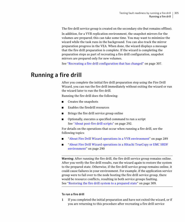
305Testing fault readiness by running a fire drillRunning a fire drill
The fire drill service group is created on the secondary site (but remains offline).
In addition, for a VVR replication environment, the snapshot mirrors for the volumes are prepared; this can take some time. You may want to minimize the wizard while the task runs in the background. You can also track the mirror preparation progress in the VEA. When done, the wizard displays a message that the fire drill preparation is complete. If the wizard is completing the preparation steps as part of recreating a fire drill configuration, snapshot mirrors are prepared only for new volumes.
See “Recreating a fire drill configuration that has changed” on page 307.
Running a fire drillAfter you complete the initial fire drill preparation step using the Fire Drill Wizard, you can run the fire drill immediately without exiting the wizard or run the wizard later to run the fire drill.
Running the fire drill does the following:
■ Creates the snapshots
■ Enables the firedrill resources
■ Brings the fire drill service group online
■ Optionally, executes a specified command to run a script
See “About post-fire drill scripts” on page 292.
For details on the operations that occur when running a fire drill, see the following topics:
■ “About Fire Drill Wizard operations in a VVR environment” on page 289
■ “About Fire Drill Wizard operations in a Hitachi TrueCopy or EMC SRDF environment” on page 290
Warning: After running the fire drill, the fire drill service group remains online. After you verify the fire drill results, run the wizard again to restore the system to the prepared state. Otherwise, if the fire drill service group remains online, it could cause failures in your environment. For example, if the application service group were to fail over to the node hosting the fire drill service group, there would be resource conflicts, resulting in both service groups faulting.See “Restoring the fire drill system to a prepared state” on page 309.
To run a fire drill
1 If you completed the initial preparation and have not exited the wizard, or if you are returning to this procedure after recreating a fire drill service
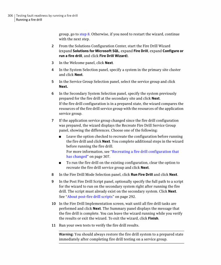
306 Testing fault readiness by running a fire drillRunning a fire drill
group, go to step 8. Otherwise, if you need to restart the wizard, continue with the next step.
2 From the Solutions Configuration Center, start the Fire Drill Wizard (expand Solutions for Microsoft SQL, expand Fire Drill, expand Configure or run a fire drill, and click Fire Drill Wizard).
3 In the Welcome panel, click Next.
4 In the System Selection panel, specify a system in the primary site cluster and click Next.
5 In the Service Group Selection panel, select the service group and click Next.
6 In the Secondary System Selection panel, specify the system previously prepared for the fire drill at the secondary site and click Next.
If the fire drill configuration is in a prepared state, the wizard compares the resources of the fire drill service group with the resources of the application service group.
7 If the application service group changed since the fire drill configuration was prepared, the wizard displays the Recreate Fire Drill Service Group panel, showing the differences. Choose one of the following:
■ Leave the option checked to recreate the configuration before running the fire drill and click Next. You complete additional steps in the wizard before running the fire drill.
For more information, see “Recreating a fire drill configuration that has changed” on page 307.
■ To run the fire drill on the existing configuration, clear the option to recreate the fire drill service group and click Next.
8 In the Fire Drill Mode Selection panel, click Run Fire Drill and click Next.
9 In the Post Fire Drill Script panel, optionally specify the full path to a script for the wizard to run on the secondary system right after running the fire drill. The script must already exist on the secondary system. Click Next.
See “About post-fire drill scripts” on page 292.
10 In the Fire Drill Implementation screen, wait until all fire drill tasks are performed and click Next. The Summary panel displays the message that the fire drill is complete. You can leave the wizard running while you verify the results or exit the wizard. To exit the wizard, click Finish.
11 Run your own tests to verify the fire drill results.
Warning: You should always restore the fire drill system to a prepared state immediately after completing fire drill testing on a service group.
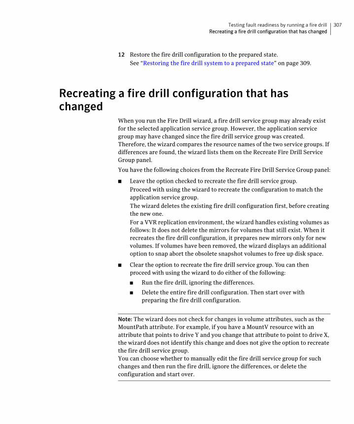
307Testing fault readiness by running a fire drillRecreating a fire drill configuration that has changed
12 Restore the fire drill configuration to the prepared state.
See “Restoring the fire drill system to a prepared state” on page 309.
Recreating a fire drill configuration that has changed
When you run the Fire Drill wizard, a fire drill service group may already exist for the selected application service group. However, the application service group may have changed since the fire drill service group was created. Therefore, the wizard compares the resource names of the two service groups. If differences are found, the wizard lists them on the Recreate Fire Drill Service Group panel.
You have the following choices from the Recreate Fire Drill Service Group panel:
■ Leave the option checked to recreate the fire drill service group.
Proceed with using the wizard to recreate the configuration to match the application service group.
The wizard deletes the existing fire drill configuration first, before creating the new one.
For a VVR replication environment, the wizard handles existing volumes as follows: It does not delete the mirrors for volumes that still exist. When it recreates the fire drill configuration, it prepares new mirrors only for new volumes. If volumes have been removed, the wizard displays an additional option to snap abort the obsolete snapshot volumes to free up disk space.
■ Clear the option to recreate the fire drill service group. You can then proceed with using the wizard to do either of the following:
■ Run the fire drill, ignoring the differences.
■ Delete the entire fire drill configuration. Then start over with preparing the fire drill configuration.
Note: The wizard does not check for changes in volume attributes, such as the MountPath attribute. For example, if you have a MountV resource with an attribute that points to drive Y and you change that attribute to point to drive X, the wizard does not identify this change and does not give the option to recreate the fire drill service group. You can choose whether to manually edit the fire drill service group for such changes and then run the fire drill, ignore the differences, or delete the configuration and start over.
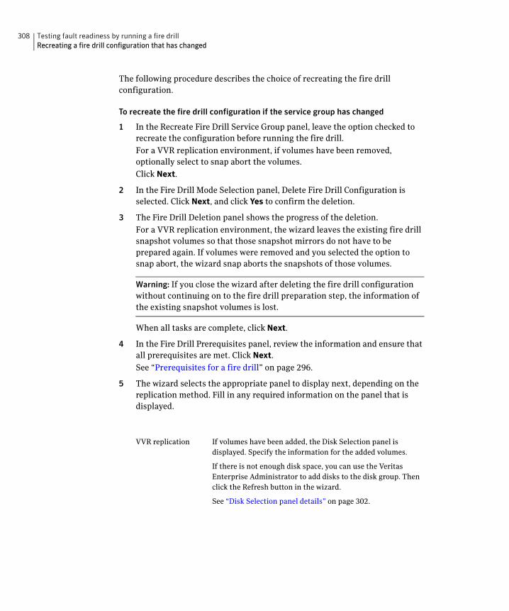
308 Testing fault readiness by running a fire drillRecreating a fire drill configuration that has changed
The following procedure describes the choice of recreating the fire drill configuration.
To recreate the fire drill configuration if the service group has changed
1 In the Recreate Fire Drill Service Group panel, leave the option checked to recreate the configuration before running the fire drill.
For a VVR replication environment, if volumes have been removed, optionally select to snap abort the volumes.
Click Next.
2 In the Fire Drill Mode Selection panel, Delete Fire Drill Configuration is selected. Click Next, and click Yes to confirm the deletion.
3 The Fire Drill Deletion panel shows the progress of the deletion.
For a VVR replication environment, the wizard leaves the existing fire drill snapshot volumes so that those snapshot mirrors do not have to be prepared again. If volumes were removed and you selected the option to snap abort, the wizard snap aborts the snapshots of those volumes.
Warning: If you close the wizard after deleting the fire drill configuration without continuing on to the fire drill preparation step, the information of the existing snapshot volumes is lost.
When all tasks are complete, click Next.
4 In the Fire Drill Prerequisites panel, review the information and ensure that all prerequisites are met. Click Next.
See “Prerequisites for a fire drill” on page 296.
5 The wizard selects the appropriate panel to display next, depending on the replication method. Fill in any required information on the panel that is displayed.
VVR replication If volumes have been added, the Disk Selection panel is displayed. Specify the information for the added volumes.
If there is not enough disk space, you can use the Veritas Enterprise Administrator to add disks to the disk group. Then click the Refresh button in the wizard.
See “Disk Selection panel details” on page 302.
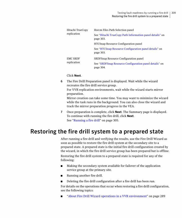
309Testing fault readiness by running a fire drillRestoring the fire drill system to a prepared state
Click Next.
6 The Fire Drill Preparation panel is displayed. Wait while the wizard recreates the fire drill service group.
For VVR replication environments, wait while the wizard starts mirror preparation.
Mirror creation can take some time. You may want to minimize the wizard while the task runs in the background. You can also close the wizard and track the mirror preparation progress in the VEA.
7 Once preparation is complete, click Next. The Summary page is displayed. To continue with running the fire drill, click Next.
See “Running a fire drill” on page 305.
Restoring the fire drill system to a prepared stateAfter running a fire drill and verifying the results, use the Fire Drill Wizard as soon as possible to restore the fire drill system at the secondary site to a prepared state. A prepared state is the initial fire drill configuration created by the wizard, in which the fire drill service group has been prepared but is offline.
Restoring the fire drill system to a prepared state is required for any of the following:
■ Making the secondary system available for failover of the application service group at the primary site.
■ Running another fire drill.
■ Deleting the fire drill configuration after a fire drill has been run.
For details on the operations that occur when restoring a fire drill configuration, see the following topics:
■ “About Fire Drill Wizard operations in a VVR environment” on page 289
Hitachi TrueCopy replication
Horcm Files Path Selection panel
See “Hitachi TrueCopy Path Information panel details” on page 303.
HTCSnap Resource Configuration panel
See “HTCSnap Resource Configuration panel details” on page 303.
EMC SRDF replication
SRDFSnap Resource Configuration panel
See “SRDFSnap Resource Configuration panel details” on page 304.
310 Testing fault readiness by running a fire drillDeleting the fire drill configuration
■ “About Fire Drill Wizard operations in a Hitachi TrueCopy or EMC SRDF environment” on page 290
To restore the fire drill system to a prepared state
1 If you completed running a fire drill and have not exited the wizard, go to step 8. Otherwise, continue with the next step.
2 From the Solutions Configuration Center, start the Fire Drill Wizard (expand Solutions for Microsoft SQL, expand Fire Drill, expand Configure or run a fire drill, and click Fire Drill Wizard).
3 In the Welcome panel, click Next.
4 In the System Selection panel, specify a system in the primary site cluster and click Next.
The default system is the node where you launched the wizard.
5 In the Service Group Selection panel, select the service group that was used for the fire drill and click Next.
6 In the Secondary System Selection panel, specify the system on which the fire drill was run at the secondary site.
7 In the Fire Drill Restoration Information panel, review the requirements for restoration and click Next.
8 In the Fire Drill Restoration screen, wait until the screen shows the restoration tasks are completed and click Next.
9 In the Summary screen, click Next if you want to delete the fire drill configuration. Otherwise click Finish to exit the wizard, leaving the fire drill configuration in a prepared state.
Deleting the fire drill configurationIf you no longer need a fire drill configuration you can delete it.
Deleting a fire drill configuration deletes the fire drill service group on the secondary site.
In a VVR replication environment, deleting a fire drill configuration also performs a snap abort of the snapshot mirrors created on the secondary site for use in the fire drill. It frees up the disk space used for the snapshot mirrors for other use.
In a Hitachi TrueCopy or EMC SRDF environment, you could manually remove mirrors after the deletion is complete.
311Testing fault readiness by running a fire drillDeleting the fire drill configuration
To delete a fire drill configuration
1 If you have just used the wizard to prepare or restore a fire drill configuration and have not exited the wizard, go to step 10. Otherwise continue with the next step.
2 From the Solutions Configuration Center, start the Fire Drill Wizard (expand Solutions for Microsoft SQL, expand Fire Drill, expand Configure or run a fire drill, and click Fire Drill Wizard).
3 In the Welcome panel, click Next.
4 In the System Selection panel, specify a system in the primary site cluster and click Next.
The default system is the node where you launched the wizard.
5 In the Service Group Selection panel, select the service group that was used for the fire drill and click Next.
6 In the Secondary System Selection panel, specify the system on which the fire drill was run at the secondary site.
7 If the wizard detects that the fire drill service group is different from the application service group, it displays the Recreate Fire Drill Service Group panel. Clear the option to recreate the fire drill service group and click Next.
8 If the wizard detects that the fire drill service group is still online, the Fire Drill Restoration panel is displayed. Review the requirements for restoration and click Next.
9 In the Restore Fire Drill screen, wait until the screen shows the restoration tasks are completed. Then click Next.
10 In the Fire Drill Mode Selection panel, click Delete Fire Drill Configuration and click Next, and click Yes to confirm the deletion.
11 The Fire Drill Deletion panel shows the progress of the deletion. Wait until all tasks are complete and then click Next.
If errors occur while deleting the fire drill configuration, the wizard will list any incomplete steps so that you can complete them manually.
12 The Summary panel is displayed. Click Finish.

312 Testing fault readiness by running a fire drillDeleting the fire drill configuration
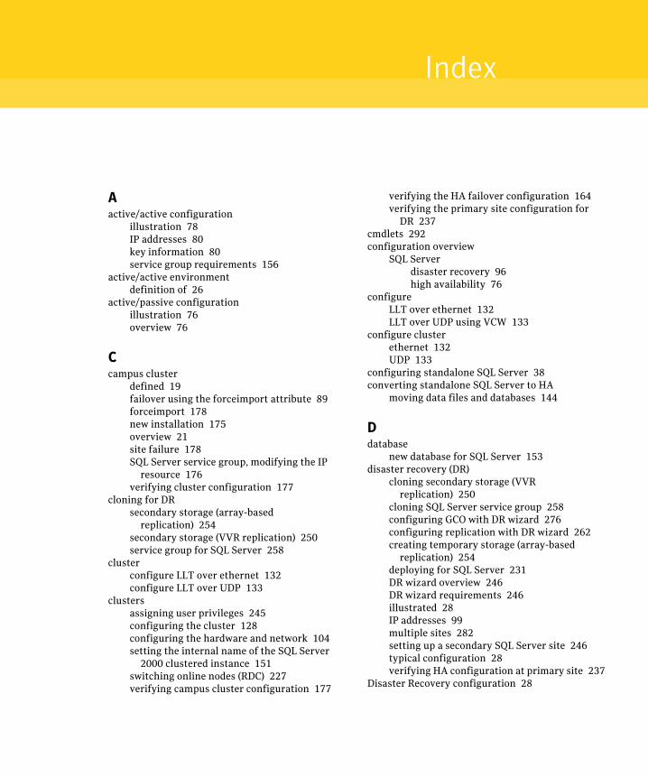
Index
Aactive/active configuration
illustration 78IP addresses 80key information 80service group requirements 156
active/active environmentdefinition of 26
active/passive configurationillustration 76overview 76
Ccampus cluster
defined 19failover using the forceimport attribute 89forceimport 178new installation 175overview 21site failure 178SQL Server service group, modifying the IP
resource 176verifying cluster configuration 177
cloning for DRsecondary storage (array-based
replication) 254secondary storage (VVR replication) 250service group for SQL Server 258
clusterconfigure LLT over ethernet 132configure LLT over UDP 133
clustersassigning user privileges 245configuring the cluster 128configuring the hardware and network 104setting the internal name of the SQL Server
2000 clustered instance 151switching online nodes (RDC) 227verifying campus cluster configuration 177
verifying the HA failover configuration 164verifying the primary site configuration for
DR 237cmdlets 292configuration overview
SQL Serverdisaster recovery 96high availability 76
configureLLT over ethernet 132LLT over UDP using VCW 133
configure clusterethernet 132UDP 133
configuring standalone SQL Server 38converting standalone SQL Server to HA
moving data files and databases 144
Ddatabase
new database for SQL Server 153disaster recovery (DR)
cloning secondary storage (VVR replication) 250
cloning SQL Server service group 258configuring GCO with DR wizard 276configuring replication with DR wizard 262creating temporary storage (array-based
replication) 254deploying for SQL Server 231DR wizard overview 246DR wizard requirements 246illustrated 28IP addresses 99multiple sites 282setting up a secondary SQL Server site 246typical configuration 28verifying HA configuration at primary site 237
Disaster Recovery configuration 28
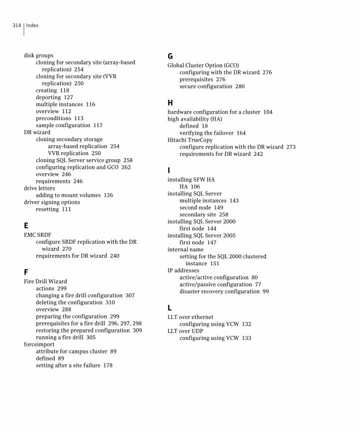
314 Index
disk groupscloning for secondary site (array-based
replication) 254cloning for secondary site (VVR
replication) 250creating 118deporting 127multiple instances 116overview 112preconditions 113sample configuration 117
DR wizardcloning secondary storage
array-based replication 254VVR replication 250
cloning SQL Server service group 258configuring replication and GCO 262overview 246requirements 246
drive lettersadding to mount volumes 126
driver signing optionsresetting 111
EEMC SRDF
configure SRDF replication with the DR wizard 270
requirements for DR wizard 240
FFire Drill Wizard
actions 299changing a fire drill configuration 307deleting the configuration 310overview 288preparing the configuration 299prerequisites for a fire drill 296, 297, 298restoring the prepared configuration 309running a fire drill 305
forceimportattribute for campus cluster 89defined 89setting after a site failure 178
GGlobal Cluster Option (GCO)
configuring with the DR wizard 276prerequisites 276secure configuration 280
Hhardware configuration for a cluster 104high availability (HA)
defined 18verifying the failover 164
Hitachi TrueCopyconfigure replication with the DR wizard 273requirements for DR wizard 242
Iinstalling SFW HA
HA 106installing SQL Server
multiple instances 143second node 149secondary site 258
installing SQL Server 2000first node 144
installing SQL Server 2005first node 147
internal namesetting for the SQL 2000 clustered
instance 151IP addresses
active/active configuration 80active/passive configuration 77disaster recovery configuration 99
LLLT over ethernet
configuring using VCW 132LLT over UDP
configuring using VCW 133
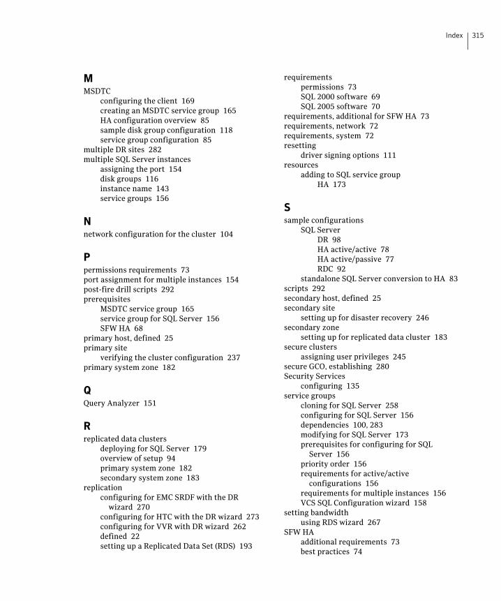
315Index
MMSDTC
configuring the client 169creating an MSDTC service group 165HA configuration overview 85sample disk group configuration 118service group configuration 85
multiple DR sites 282multiple SQL Server instances
assigning the port 154disk groups 116instance name 143service groups 156
Nnetwork configuration for the cluster 104
Ppermissions requirements 73port assignment for multiple instances 154post-fire drill scripts 292prerequisites
MSDTC service group 165service group for SQL Server 156SFW HA 68
primary host, defined 25primary site
verifying the cluster configuration 237primary system zone 182
QQuery Analyzer 151
Rreplicated data clusters
deploying for SQL Server 179overview of setup 94primary system zone 182secondary system zone 183
replicationconfiguring for EMC SRDF with the DR
wizard 270configuring for HTC with the DR wizard 273configuring for VVR with DR wizard 262defined 22setting up a Replicated Data Set (RDS) 193
requirementspermissions 73SQL 2000 software 69SQL 2005 software 70
requirements, additional for SFW HA 73requirements, network 72requirements, system 72resetting
driver signing options 111resources
adding to SQL service groupHA 173
Ssample configurations
SQL ServerDR 98HA active/active 78HA active/passive 77RDC 92
standalone SQL Server conversion to HA 83scripts 292secondary host, defined 25secondary site
setting up for disaster recovery 246secondary zone
setting up for replicated data cluster 183secure clusters
assigning user privileges 245secure GCO, establishing 280Security Services
configuring 135service groups
cloning for SQL Server 258configuring for SQL Server 156dependencies 100, 283modifying for SQL Server 173prerequisites for configuring for SQL
Server 156priority order 156requirements for active/active
configurations 156requirements for multiple instances 156VCS SQL Configuration wizard 158
setting bandwidthusing RDS wizard 267
SFW HAadditional requirements 73best practices 74
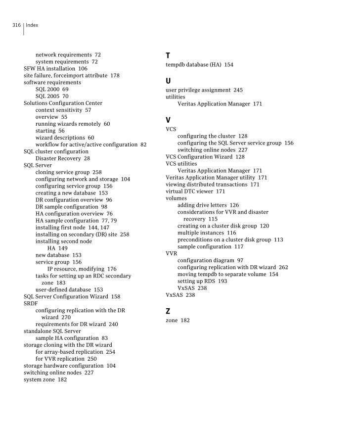
316 Index
network requirements 72system requirements 72
SFW HA installation 106site failure, forceimport attribute 178software requirements
SQL 2000 69SQL 2005 70
Solutions Configuration Centercontext sensitivity 57overview 55running wizards remotely 60starting 56wizard descriptions 60workflow for active/active configuration 82
SQL cluster configurationDisaster Recovery 28
SQL Servercloning service group 258configuring network and storage 104configuring service group 156creating a new database 153DR configuration overview 96DR sample configuration 98HA configuration overview 76HA sample configuration 77, 79installing first node 144, 147installing on secondary (DR) site 258installing second node
HA 149new database 153service group 156
IP resource, modifying 176tasks for setting up an RDC secondary
zone 183user-defined database 153
SQL Server Configuration Wizard 158SRDF
configuring replication with the DR wizard 270
requirements for DR wizard 240standalone SQL Server
sample HA configuration 83storage cloning with the DR wizard
for array-based replication 254for VVR replication 250
storage hardware configuration 104switching online nodes 227system zone 182
Ttempdb database (HA) 154
Uuser privilege assignment 245utilities
Veritas Application Manager 171
VVCS
configuring the cluster 128configuring the SQL Server service group 156switching online nodes 227
VCS Configuration Wizard 128VCS utilities
Veritas Application Manager 171Veritas Application Manager utility 171viewing distributed transactions 171virtual DTC viewer 171volumes
adding drive letters 126considerations for VVR and disaster
recovery 115creating on a cluster disk group 120multiple instances 116preconditions on a cluster disk group 113sample configuration 117
VVRconfiguration diagram 97configuring replication with DR wizard 262moving tempdb to separate volume 154setting up RDS 193VxSAS 238
VxSAS 238
Zzone 182