Embed Size (px)
Citation preview
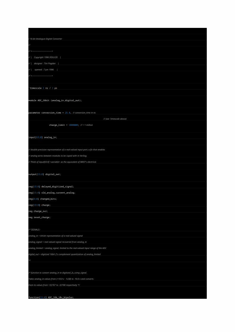
/ 16-bit Analogue-Digital Converter
//
// +-----------------------------+
// | Copyright 1996 DOULOS |
// | designer : Tim Pagden |
// | opened: 7 Jun 1996 |
// +-----------------------------+
`timescale 1 ns / 1 ps
module ADC_16bit (analog_in,digital_out);
parameter conversion_time = 25.0, // conversion_time in ns
// (see `timescale above)
charge_limit = 1000000; // = 1 million
input[63:0] analog_in;
// double-precision representation of a real-valued input port; a fix that enables
// analog wires between modules to be coped with in Verilog.
// Think of input[63:0] <variable> as the equivalent of MAST's electrical.
output[15:0] digital_out;
reg[15:0] delayed_digitized_signal;
reg[15:0] old_analog,current_analog;
reg[4:0] changed_bits;
reg[19:0] charge;
reg charge_ovr;
reg reset_charge;
/* SIGNALS:-
analog_in = 64-bit representation of a real-valued signal
analog_signal = real valued signal recovered from analog_in
analog_limited = analog_signal, limited to the real-valued input range of the ADC
digital_out = digitized 16bit 2's complement quantization of analog_limited
*/
/* function to convert analog_in to digitized_2s_comp_signal.
Takes analog_in values from (+10.0 v - 1LSB) to -10.0 v and converts
them to values from +32767 to -32768 respectively */
function[15:0] ADC_16b_10v_bipolar;
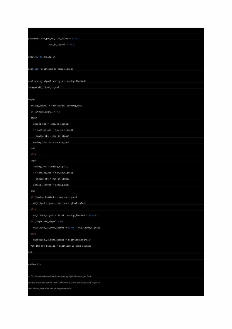
parameter max_pos_digital_value = 32767,
max_in_signal = 10.0;
input[63:0] analog_in;
reg[15:0] digitized_2s_comp_signal;
real analog_signal,analog_abs,analog_limited;
integer digitized_signal;
begin
analog_signal = $bitstoreal (analog_in);
if (analog_signal < 0.0)
begin
analog_abs = -analog_signal;
if (analog_abs > max_in_signal)
analog_abs = max_in_signal;
analog_limited = -analog_abs;
end
else
begin
analog_abs = analog_signal;
if (analog_abs > max_in_signal)
analog_abs = max_in_signal;
analog_limited = analog_abs;
end
if (analog_limited == max_in_signal)
digitized_signal = max_pos_digital_value;
else
digitized_signal = $rtoi (analog_limited * 3276.8);
if (digitized_signal < 0)
digitized_2s_comp_signal = 65536 - digitized_signal;
else
digitized_2s_comp_signal = digitized_signal;
ADC_16b_10v_bipolar = digitized_2s_comp_signal;
end
endfunction
/* This function determines the number of digital bit changes from
sample to sample; can be used to determine power consumption if required.
Task power_determine not yet implemented */
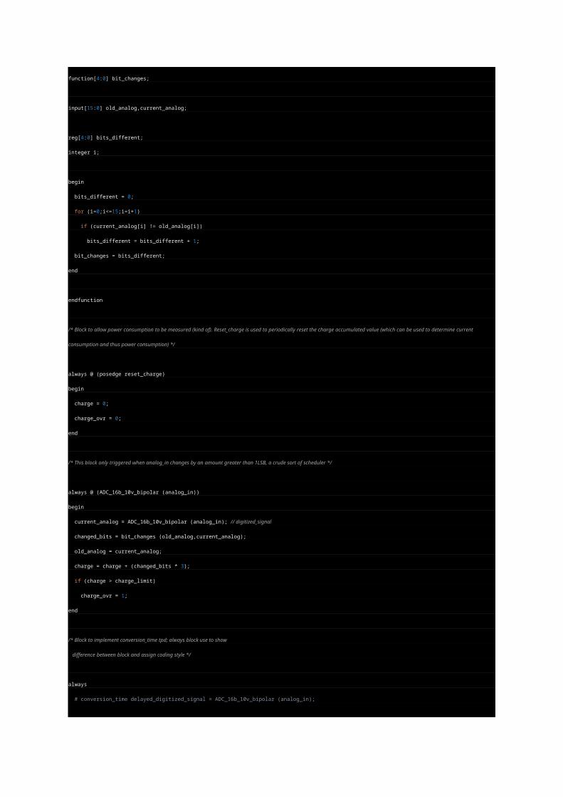
function[4:0] bit_changes;
input[15:0] old_analog,current_analog;
reg[4:0] bits_different;
integer i;
begin
bits_different = 0;
for (i=0;i<=15;i=i+1)
if (current_analog[i] != old_analog[i])
bits_different = bits_different + 1;
bit_changes = bits_different;
end
endfunction
/* Block to allow power consumption to be measured (kind of). Reset_charge is used to periodically reset the charge accumulated value (which can be used to
determine current consumption and thus power consumption) */
always @ (posedge reset_charge)
begin
charge = 0;
charge_ovr = 0;
end
/* This block only triggered when analog_in changes by an amount greater than 1LSB, a crude sort of scheduler */
always @ (ADC_16b_10v_bipolar (analog_in))
begin
current_analog = ADC_16b_10v_bipolar (analog_in); // digitized_signal
changed_bits = bit_changes (old_analog,current_analog);
old_analog = current_analog;
charge = charge + (changed_bits * 3);
if (charge > charge_limit)
charge_ovr = 1;
end
/* Block to implement conversion_time tpd; always block use to show
difference between block and assign coding style */
always
# conversion_time delayed_digitized_signal = ADC_16b_10v_bipolar (analog_in);
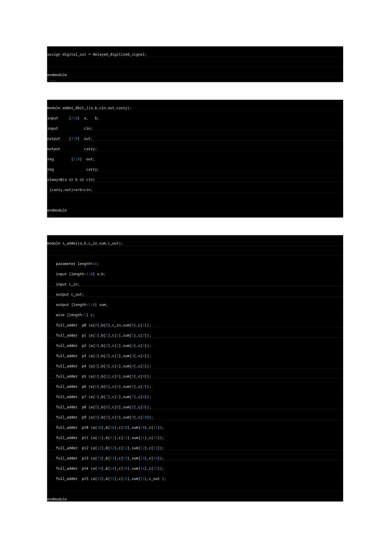
assign digital_out = delayed_digitized_signal;
endmodule ...
module adder_8bit_1(a,b,cin,out,carry);
input [7:0] a, b;
input cin;
output [7:0] out;
output carry;
reg [7:0] out;
reg carry;
always@(a or b or cin)
{carry,out}=a+b+cin;
endmodule ...
module s_adder(a,b,c_in,sum,c_out);
parameter length=16;
input [length-1:0] a,b;
input c_in;
output c_out;
output [length-1:0] sum;
wire [length:1] c;
full_adder p0 (a[0],b[0],c_in,sum[0],c[1]);
full_adder p1 (a[1],b[1],c[1],sum[1],c[2]);
full_adder p2 (a[2],b[2],c[2],sum[2],c[3]);
full_adder p3 (a[3],b[3],c[3],sum[3],c[4]);
full_adder p4 (a[4],b[4],c[4],sum[4],c[5]);
full_adder p5 (a[6],b[5],c[5],sum[5],c[6]);
full_adder p6 (a[6],b[6],c[6],sum[6],c[7]);
full_adder p7 (a[7],b[7],c[7],sum[7],c[8]);
full_adder p8 (a[8],b[8],c[8],sum[8],c[9]);
full_adder p9 (a[9],b[9],c[9],sum[9],c[10]);
full_adder p10 (a[10],b[10],c[10],sum[10],c[11]);
full_adder p11 (a[11],b[11],c[11],sum[11],c[12]);
full_adder p12 (a[12],b[12],c[12],sum[12],c[13]);
full_adder p13 (a[13],b[13],c[13],sum[13],c[14]);
full_adder p14 (a[14],b[14],c[14],sum[14],c[15]);
full_adder p15 (a[15],b[15],c[15],sum[15],c_out );
endmodule
...
module all (a,b,y);
input [7:0] a,b;
output [8:0] y;
function [8:0] add_It_10;
input [7:0] a,b;
reg [7:0] temp;
begin
if(b<10)
temp=b;
else
temp=10;
add_It_10=a+temp[3:0];
end
endfunction
assign y=add_It_10(a,b);
endmodule ...
module binarytogray (clk, reset, binary_input, gray_output);
input clk, reset;
input [3:0] binary_input;
output gray_output;
reg [3:0] gray_output;
always @ (posedge clk or posedge reset)
if (reset)
begin
gray_output <= 4'b0;
end
else begin
gray_output[3] <= binary_input[3];
gray_output[2] <= binary_input[3] ^ binary_input[2];
gray_output[1] <= binary_input[2] ^ binary_input[1];
gray_output[0] <= binary_input[1] ^ binary_input[0];
endendmodule
module cla_8bits(a,b,c0,c8,s);
input [7:0] a,b;
input c0;
output c8;
output [7:0] s;
reg [7:0] p,q;
reg [7:1] c;
reg [7:0] s;
reg c8;
always@(a or b or c0)
begin
p=a|b;
q=a&b;
c[1]=q[0] | p[0]&c0;
c[2]=q[1] | p[1]&q[0] | p[1]&p[0]&c0;
c[3]=q[2] | p[2]&q[1] | p[2]&p[1]&q[0] | p[2]&p[1]&p[0]&c0;
c[4]=q[3] | p[3]&q[2] | p[3]&p[2]&q[1] | p[3]&p[2]&p[1]&q[0] | p[3]&p[2]&p[1]&p[0]&c0;
c[5]=q[4] | p[4]&q[3] | p[4]&p[3]&q[2] | p[4]&p[3]&p[2]&q[1] | p[4]&p[3]&p[2]&p[1]&q[0] | p[4]&p[3]&p[2]&p[1]&p[0]&c0;
c[6]=q[5] | p[5]&q[4] | p[5]&p[4]&q[3] | p[5]&p[4]&p[3]&q[2] | p[5]&p[4]&p[3]&p[2]&q[1] | p[5]&p[4]&p[3]&p[2]&p[1]&q[0] |
p[5]&p[4]&p[3]&p[2]&p[1]&p[0]&c0;
c[7]=q[6] | p[6]&q[5] | p[6]&p[5]&q[4] | p[6]&p[5]&p[4]&q[3] | p[6]&p[5]&p[4]&p[3]&q[2] | p[6]&p[5]&p[4]&p[3]&p[2]&q[1] |
p[6]&p[5]&p[4]&p[3]&p[2]&p[1]&q[0] | p[6]&p[5]&p[4]&p[3]&p[2]&p[1]&p[0]&c0;
c8 =q[7] | p[7]&q[6] | p[7]&p[6]&q[5] | p[7]&p[6]&p[5]&q[4] | p[7]&p[6]&p[5]&p[4]&q[3] | p[7]&p[6]&p[5]&p[4]&p[3]&q[2] |
p[7]&p[6]&p[5]&p[4]&p[3]&p[2]&q[1] | p[7]&p[6]&p[5]&p[4]&p[3]&p[2]&p[1]&q[0] | p[7]&p[6]&p[5]&p[4]&p[3]&p[2]&p[1]&p[0]&c0;
s[0]=p[0]^q[0]^c0;
s[1]=p[1]^q[1]^c[1];
s[2]=p[2]^q[2]^c[2];
s[3]=p[3]^q[3]^c[3];
s[4]=p[4]^q[4]^c[4];
s[5]=p[5]^q[5]^c[5];
s[6]=p[6]^q[6]^c[6];
s[7]=p[7]^q[7]^c[7];
end
endmodule
module compare(a,b,equal);
parameter size=1;
input [size-1:0]a,b;
output equal;
assign equal=(a==b)?1:0;
endmodule ...
//
//
// This is just a little demo of DDS. It doesn't have any cool features
// or anything..
//
module dds (
clk,
reset,
din,
dout
);
parameter W = 12;
input clk; // Primary clock.
input reset; // Synchronous reset.
input [W-1:0] din; // The "phase step".
output [W-1:0] dout; // Output of the phase accumulator register.
reg [W-1:0] dout;
reg [W-1:0] accum; // Phas Accumulator
// Just output the accumulator...
always @(accum)
dout <= accum;
// Specify the accumulator..
always @(posedge clk) begin
if (reset) accum <= 0;
else begin
accum <= accum + din;
end
end
endmodule
// synopsys translate_off
module ddstest;
reg clk;
reg reset;
reg [11:0] din;
wire [11:0] dout;
reg [7:0] cosout;
// Instantiate the DDS with 12-bits.
//
dds #(12) dds1 (.clk(clk), .reset(reset), .din(din), .dout(dout));
// Here's our Cosine lookup table.
//
reg [7:0] costable[0:4095]; // 4KBytes.
// DDS Phase Accumulator output simply indexes into the Cos lookup table.
//
always @(dout)
cosout <= costable[dout];
// Main test thread.
//
initial begin
$readmemh ("cos.hex", costable); // See the PERL program 'generate_cos_table.pl'
din = 12'h020; // Start at 16
#500000;
din = 12'h0D0; // A little faster..
#500000;
din = 12'h200; // Fairly fast.
#500000;
$finish;
end
// Let's clock it at 1 MHz
initial begin
clk = 0;
forever begin
#500 clk = 1;
#500 clk = 0;
end
end
// Reset
initial begin
reset = 1;
#3500 reset = 0;
end
// Generate VCD file for viewing.
initial begin
$dumpfile ("dds.vcd");
$dumpvars (0,ddstest);
end
endmodule
//*** Here's the Perl program for your reference...
`ifdef WHEN_PERL_IS_A_SUBSET_OF_VERILOG
#!/tools2/perl/bin/perl
#
# Generate a file of cos data for use by a DDS simulation.
#
$n = 4096; # Number of data points
$minval = 0; # Smallest cos value.
$maxval = 255; # Largest cos value.
$pi = 3.1415927;
$t = 0;
for ($i = 1; $i < $n; $i = $i + 1) {
$value = ($maxval - $minval)/2 + (($maxval - $minval)/2)*cos($t);
$value = int($value);
printf "%x\n", $value;
$t = $t + 2*$pi / $n;
}
`endif ...
module decoder(out,in);
output [7:0] out;
input [2:0] in;
assign out=1'b1<<in;endmodule ...
'timesclae 1ns/1ps
module decoder3x8(a,b,c,en,z);
input a,b,c,en;
output [0:7] z;
wire nota,notb,notc;
assign #1 nota = ~a;
assign #1 notb = ~b;
assign #1 notc = ~c;
assign #2 z[0] = nota & notb & notc & en;
assign #2 z[1] = a & notb & notc & en;
assign #2 z[2] = nota & b & notc & en;
assign #2 z[3] = a & b & notc & en;
assign #2 z[4] = nota & notb & c & en;
assign #2 z[5] = a & notb & c & en;
assign #2 z[6] = nota & b & c & en;
assign #2 z[7] = a & b & c & en;
endmodule ...
module div16 (clk, resetb, start, a, b, q, r, done);
parameter N = 16; // a/b = q remainder r, where all operands are N wide.
input clk;
input resetb; // Asynchronous, active low reset.
input start; // Pulse this to start the division.
input [N-1:0] a; // This is the number we are dividing (the dividend)
input [N-1:0] b; // This is the 'divisor'
output [N-1:0] q; // This is the 'quotient'
output [N-1:0] r; // Here is the remainder.
output done; // Will be asserted when q and r are available.
// Registered q
reg [N-1:0] q;
reg done;
// Power is the current 2^n bit we are considering. Power is a shifting
// '1' that starts at the highest power of 2 and goes all the way down
// to ...00001 Shift this until it is zero at which point we stop.
//
reg [N-1:0] power;
// This is the accumulator. We are start with the accumulator set to 'a' (the dividend).
// For each (divisor*2^N) term, we see if we can subtract (divisor*2^N) from the accumulator.
// We subtract these terms as long as adding in the term doesn't cause the accumulator
// to exceed a. When we are done, whatever is left in the accumulator is the remainder.
//
reg [N-1:0] accum;
// This is the divisor*2^N term. Essentually, we are taking the divisor ('b'), initially
// shifting it all the way to the left, and shifting it 1 bit at a time to the right.
//
reg [(2*N-1):0] bpower;
// Remainder will be whatever is left in the accumulator.
assign r = accum;
// Do this addition here for resource sharing.
// ** Note that 'accum' is N bits wide, but bpower is 2*N-1 bits wide **
//
wire [2*N-1:0] accum_minus_bpower = accum - bpower;
always @(posedge clk or negedge resetb) begin
if (~resetb) begin
q <= 0;
accum <= 0;
power <= 0;
bpower <= 0;
done <= 0;
end
else begin
if (start) begin
// Reinitialize the divide circuit.
q <= 0;
accum <= a; // Accumulator initially gets the dividend.
power[N-1] <= 1'b1; // We start with highest power of 2 (which is a '1' in MSB)
bpower <= b << N-1; // Start with highest bpower, which is (divisor * 2^(N-1))
done <= 0;
end
else begin
// Go until power is zero.
//
if (power != 0) begin
//
// Can we add this divisor*2^(power) to the accumulator without going negative?
// Just test the MSB of the subtraction. If it is '1', then it must be negative.
//
if ( ~accum_minus_bpower[2*N-1]) begin
// Yes! Set this power of 2 in the quotieny and
// then actually comitt to the subtraction from our accumulator.
//
q <= q | power;
accum <= accum_minus_bpower;
end
// Regardless, always go to next lower power of 2.
//
power <= power >> 1;
bpower <= bpower >> 1;
end
else begin
// We're done. Set done flag.
done <= 1;
end
end
end
end
endmodule
// synopsys translate_off
module test_div16;
reg clk;
reg resetb;
reg start;
reg [15:0] a;
reg [15:0] b;
wire [15:0] q;
wire [15:0] r;
wire done;
integer num_errors;
div16 div16 (
.clk(clk),
.resetb(resetb),
.start(start),
.a(a),
.b(b),
.q(q),
.r(r),
.done(done)
);
initial begin
num_errors = 0;
start = 0;
// Wait till reset is completely over.
#200;
// Do some divisions where divisor is constrained to 8-bits and dividend is 16-bits
$display ("16-bit Dividend, 8-bit divisor");
repeat (25) begin
do_divide ($random, $random & 255);
end
// Do some divisions where divisor is constrained to 12-bits and dividend is 16-bits
$display ("\n16-bit Dividend, 12-bit divisor");
repeat (25) begin
do_divide ($random, $random & 4095);
end
// Do some divisions where both divisor and dividend is 16-bits
$display ("\n16-bit Dividend, 16-bit divisor");
repeat (25) begin
do_divide ($random, $random);
end
// Special cases
$display ("\nSpecial Cases:");
do_divide (16'hFFFF, 16'hFFFF); // largest possible quotient
do_divide (312, 1); // divide by 1
do_divide ( 0, 42); // divide 0 by something else
do_divide (312, 0); // divide by zero
// That's all. Summarize the test.
if (num_errors === 0) begin
$display ("\n\nSUCCESS. There were %0d Errors.", num_errors);
end
else begin
$display ("\n\nFAILURE!! There were %0d Errors.", num_errors);
end
$finish;
end
task do_divide;
input [15:0] arga;
input [15:0] argb;
begin
a = arga;
b = argb;
@(posedge clk);
#1 start = 1;
@(posedge clk);
#1 start = 0;
while (~done) @(posedge clk);
#1;
$display ("Circuit: %0d / %0d = %0d, rem = %0d \t\t......... Reality: %0d, rem = %0d", arga, argb, q, r, a/b, a%b);
if (b !== 0) begin
if (q !== a/b) begin
$display (" Error! Unexpected Quotient\n\n");
num_errors = num_errors + 1;
end
if (r !== a % b) begin
$display (" Error! Unexpected Remainder\n\n");
num_errors = num_errors + 1;
end
end
end
endtask
initial begin
clk = 0;
forever begin
#10 clk = 1;
#10 clk = 0;
end
end
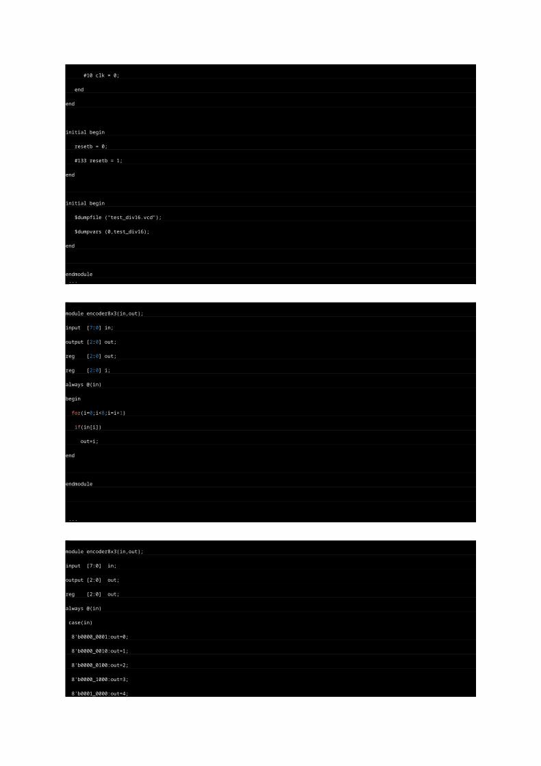
initial begin
resetb = 0;
#133 resetb = 1;
end
initial begin
$dumpfile ("test_div16.vcd");
$dumpvars (0,test_div16);
end
endmodule ...
module encoder8x3(in,out);
input [7:0] in;
output [2:0] out;
reg [2:0] out;
reg [2:0] i;
always @(in)
begin
for(i=0;i<8;i=i+1)
if(in[i])
out=i;
end
endmodule
...
module encoder8x3(in,out);
input [7:0] in;
output [2:0] out;
reg [2:0] out;
always @(in)
case(in)
8'b0000_0001:out=0;
8'b0000_0010:out=1;
8'b0000_0100:out=2;
8'b0000_1000:out=3;
8'b0001_0000:out=4;
8'b0010_0000:out=5;
8'b0100_0000:out=6;
8'b1000_0000:out=7;
endcase
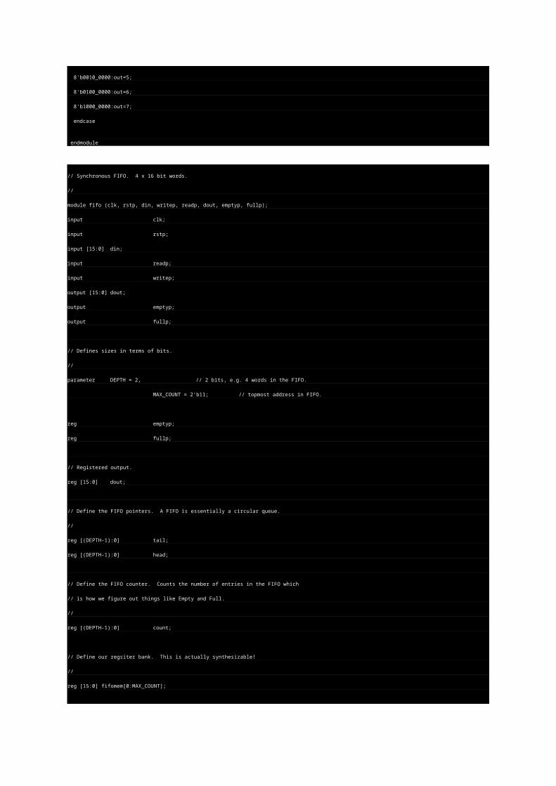
endmodule
// Synchronous FIFO. 4 x 16 bit words.
//
module fifo (clk, rstp, din, writep, readp, dout, emptyp, fullp);
input clk;
input rstp;
input [15:0] din;
input readp;
input writep;
output [15:0] dout;
output emptyp;
output fullp;
// Defines sizes in terms of bits.
//
parameter DEPTH = 2, // 2 bits, e.g. 4 words in the FIFO.
MAX_COUNT = 2'b11; // topmost address in FIFO.
reg emptyp;
reg fullp;
// Registered output.
reg [15:0] dout;
// Define the FIFO pointers. A FIFO is essentially a circular queue.
//
reg [(DEPTH-1):0] tail;
reg [(DEPTH-1):0] head;
// Define the FIFO counter. Counts the number of entries in the FIFO which
// is how we figure out things like Empty and Full.
//
reg [(DEPTH-1):0] count;
// Define our regsiter bank. This is actually synthesizable!
//
reg [15:0] fifomem[0:MAX_COUNT];
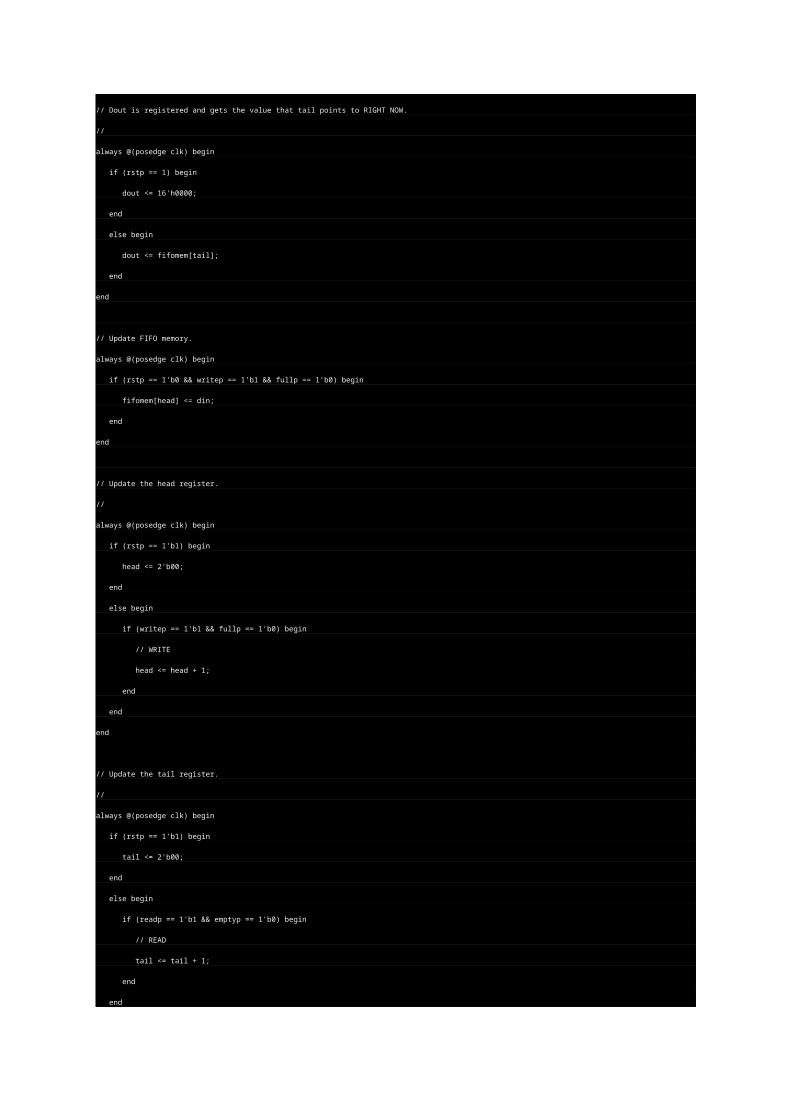
// Dout is registered and gets the value that tail points to RIGHT NOW.
//
always @(posedge clk) begin
if (rstp == 1) begin
dout <= 16'h0000;
end
else begin
dout <= fifomem[tail];
end
end
// Update FIFO memory.
always @(posedge clk) begin
if (rstp == 1'b0 && writep == 1'b1 && fullp == 1'b0) begin
fifomem[head] <= din;
end
end
// Update the head register.
//
always @(posedge clk) begin
if (rstp == 1'b1) begin
head <= 2'b00;
end
else begin
if (writep == 1'b1 && fullp == 1'b0) begin
// WRITE
head <= head + 1;
end
end
end
// Update the tail register.
//
always @(posedge clk) begin
if (rstp == 1'b1) begin
tail <= 2'b00;
end
else begin
if (readp == 1'b1 && emptyp == 1'b0) begin
// READ
tail <= tail + 1;
end
end
end
// Update the count regsiter.
//

always @(posedge clk) begin
if (rstp == 1'b1) begin
count <= 2'b00;
end
else begin
case ({readp, writep})
2'b00: count <= count;
2'b01:
// WRITE
if (count != MAX_COUNT)
count <= count + 1;
2'b10:
// READ
if (count != 2'b00)
count <= count - 1;
2'b11:
// Concurrent read and write.. no change in count
count <= count;
endcase
end
end
// *** Update the flags
//
// First, update the empty flag.
//
always @(count) begin
if (count == 2'b00)
emptyp <= 1'b1;
else
emptyp <= 1'b0;
end
// Update the full flag
//
always @(count) begin
if (count == MAX_COUNT)
fullp <= 1'b1;
else
fullp <= 1'b0;
end
endmodule
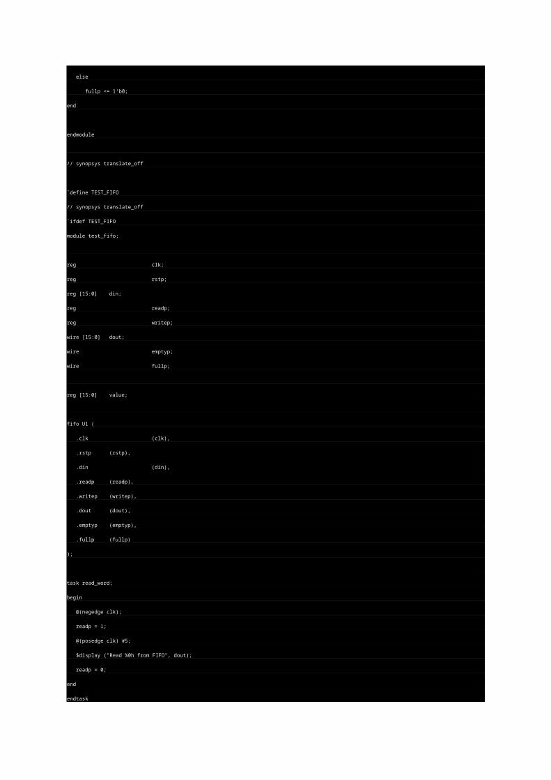
// synopsys translate_off
`define TEST_FIFO
// synopsys translate_off
`ifdef TEST_FIFO
module test_fifo;
reg clk;
reg rstp;
reg [15:0] din;
reg readp;
reg writep;
wire [15:0] dout;
wire emptyp;
wire fullp;
reg [15:0] value;
fifo U1 (
.clk (clk),
.rstp (rstp),
.din (din),
.readp (readp),
.writep (writep),
.dout (dout),
.emptyp (emptyp),
.fullp (fullp)
);
task read_word;
begin
@(negedge clk);
readp = 1;
@(posedge clk) #5;
$display ("Read %0h from FIFO", dout);
readp = 0;
end
endtask
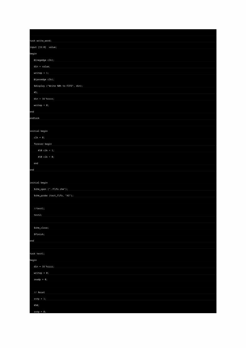
task write_word;
input [15:0] value;
begin
@(negedge clk);
din = value;
writep = 1;
@(posedge clk);
$display ("Write %0h to FIFO", din);
#5;
din = 16'hzzzz;
writep = 0;
end
endtask
initial begin
clk = 0;
forever begin
#10 clk = 1;
#10 clk = 0;
end
end
initial begin
$shm_open ("./fifo.shm");
$shm_probe (test_fifo, "AS");
//test1;
test2;
$shm_close;
$finish;
end
task test1;
begin
din = 16'hzzzz;
writep = 0;
readp = 0;
// Reset
rstp = 1;
#50;
rstp = 0;
#50;
// ** Write 3 values.
write_word (16'h1111);

write_word (16'h2222);
write_word (16'h3333);
// ** Read 2 values
read_word;
read_word;
// ** Write one more
write_word (16'h4444);
// ** Read a bunch of values
repeat (6) begin
read_word;
end
// *** Write a bunch more values
write_word (16'h0001);
write_word (16'h0002);
write_word (16'h0003);
write_word (16'h0004);
write_word (16'h0005);
write_word (16'h0006);
write_word (16'h0007);
write_word (16'h0008);
// ** Read a bunch of values
repeat (6) begin
read_word;
end
$display ("Done TEST1.");
end
endtask
// TEST2
//
// This test will operate the FIFO in an orderly manner the way it normally works.
// 2 threads are forked; a reader and a writer. The writer writes a counter to
// the FIFO and obeys the fullp flag and delays randomly. The reader likewise
// obeys the emptyp flag and reads at random intervals. The result should be that
// the reader reads the incrementing counter out of the FIFO. The empty/full flags
// should bounce around depending on the random delays. The writer repeats some
// fixed number of times and then terminates both threads and kills the sim.
//
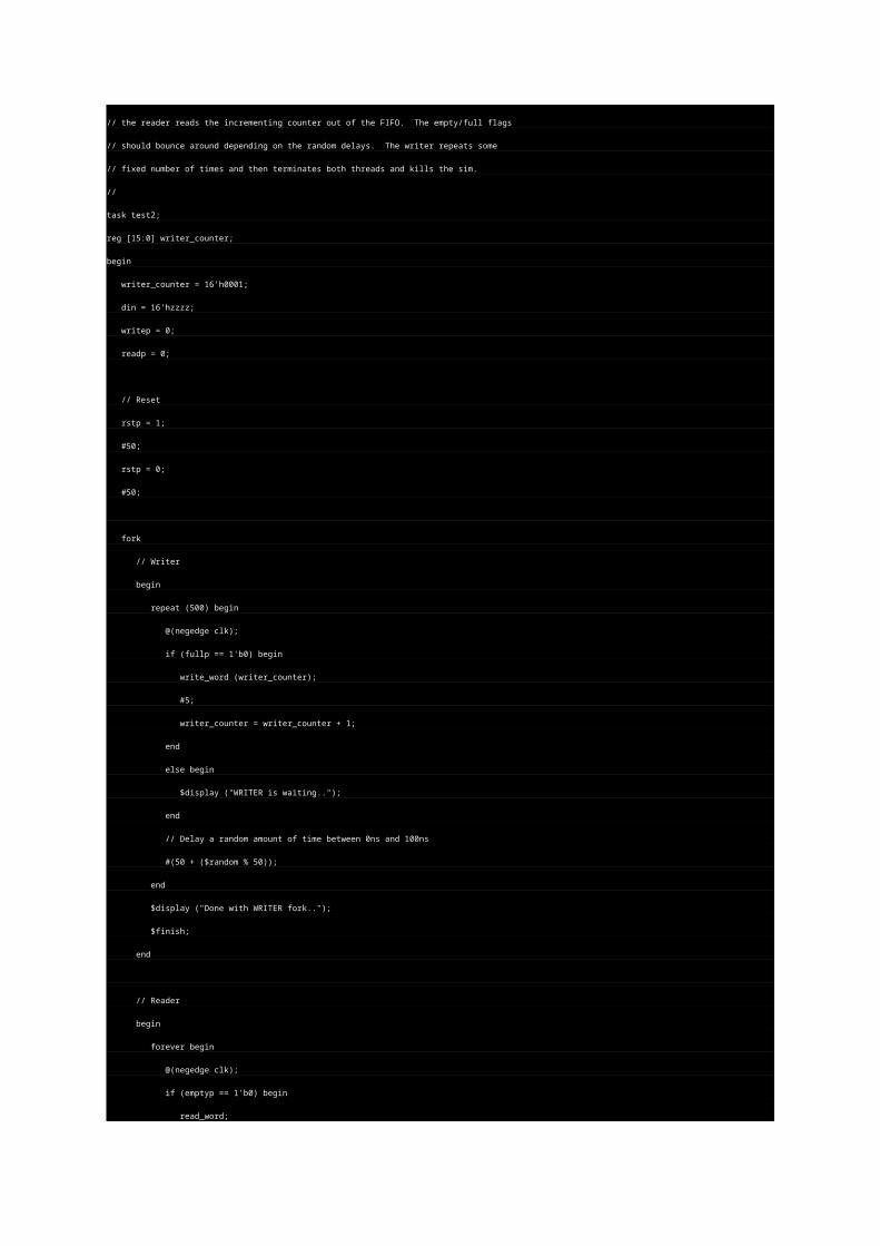
task test2;
reg [15:0] writer_counter;
begin
writer_counter = 16'h0001;
din = 16'hzzzz;
writep = 0;
readp = 0;
// Reset
rstp = 1;
#50;
rstp = 0;
#50;
fork
// Writer
begin
repeat (500) begin
@(negedge clk);
if (fullp == 1'b0) begin
write_word (writer_counter);
#5;
writer_counter = writer_counter + 1;
end
else begin
$display ("WRITER is waiting..");
end
// Delay a random amount of time between 0ns and 100ns
#(50 + ($random % 50));
end
$display ("Done with WRITER fork..");
$finish;
end
// Reader
begin
forever begin
@(negedge clk);
if (emptyp == 1'b0) begin
read_word;
end
else begin
$display ("READER is waiting..");
end
// Delay a random amount of time between 0ns and 100ns
#(50 + ($random % 50));
end
end
join
end
endtask
always @(fullp)
$display ("fullp = %0b", fullp);
always @(emptyp)
$display ("emptyp = %0b", emptyp);
always @(U1.head)
$display ("head = %0h", U1.head);
always @(U1.tail)
$display ("tail = %0h", U1.tail);
endmodule
`endif ...
module fifo(clock,reset,read,write,fifo_in,fifo_out,fifo_empty,fifo_half,fifo_full);
input clock,reset,read,write;
input [15:0] fifo_in;
output [15:0] fifo_out;
output fifo_empty,fifo_half,fifo_full;
reg [15:0] fifo_out;
reg [3:0] read_ptr,write_ptr,counter;
reg [15:0] ram [15:0];
wire fifo_empty,fifo_half,fifo_full;
always@(posedge clock)
if(reset)
begin
read_ptr =0;
write_ptr =0;
counter =0;
fifo_out =0;
end
else
case({read,write})
2'b00:counter=counter;
2'b01:begin
ram[write_ptr]=fifo_in;
counter=counter+1;
write_ptr=(write_ptr==15)?0:write_ptr+1;
end
2'b10:begin
fifo_out=ram[read_ptr];
counter=counter-1;
read_ptr=(read_ptr==15)?0:read_ptr+1;
end
2'b11:begin
if(counter==0)
fifo_out=fifo_in;
else
begin
ram[write_ptr]=fifo_in;
fifo_out=ram[read_ptr];
write_ptr=(write_ptr==15)?0:write_ptr+1;
read_ptr=(read_ptr==15)?0:read_ptr+1;
end
end
endcase
assign fifo_empty=(counter==0);
assign fifo_full=(counter==15);
assign fifo_half=(counter==8);
endmodule ...
//
// Simple example of a "framer". In this case, an MPEG framer where
// data is sent in 188-byte frames which begin with a special SYNC character
// defined as 47 hex. Framing must, of course, handle cases where 47s
// happen to also be embedded in the data. Framer must be able to find
// the period SYNC characters while not be thrown off by spurious SYNCs.
//
// This circuit uses a modulo-188 counter that serves as a timestamp.
// Every received SYNC character causes the current modulo-188 counter
// to be pushed onto a little queue. The idea is that the timestamps
// should all be the same if the data was perfectly framed. If spurious
// false SYNC characters fall in the data, then some of the timestamps
// will be different. This is OK as long as there is a clear majority.
//
// This circuit is something I started to actually have to do, but then
// I ended up not using it. It is not tested, so use it only for ideas
// and not as a proven circuit!!
//
// tom coonan, 12/1999
//
module framer (clk, resetb, din, dinstb, dout, doutsync, doutstb, locked);
input clk;
input resetb;
input [7:0] din;
input dinstb;
output [7:0] dout;
output doutsync;
output doutstb;
output locked;
parameter SYNC = 8'h47;
reg [7:0] dout;
reg doutsync;
reg doutstb;
reg locked;
/* Internals */
// Free-running Modulo-188 counter
reg [7:0] cnt188;
// Modulo-188 value when SYNCs are expected once locked.
reg [7:0] syncindex;
// 6 deep queue of timestamps of every time a SYNC character is received.
// the timestamp is the value of the modulo-188 counter when a SYNC is received.
//
reg [7:0] t0; // Oldest timestamp
reg [7:0] t1;
reg [7:0] t2;
reg [7:0] t3;
reg [7:0] t4;
reg [7:0] t5; // Newest timestamp
// Modulo-188 free-running counter.
//
always @(posedge clk or negedge resetb) begin
if (~resetb) begin
cnt188 <= 0;
end
else begin
if (dinstb) begin
if (cnt188 == 187) begin
cnt188 <= 0;
end
else begin
cnt188 <= cnt188 + 1;
end
end
end
end
// Timestamp queue.
//
always @(posedge clk or negedge resetb) begin
if (~resetb) begin
t0 <= 8'hff; // Let's use FF as an invalid indicator, otherwise
t1 <= 8'hff; // we'd potentially get a premature lock..
t2 <= 8'hff;
t3 <= 8'hff;
t4 <= 8'hff;
t5 <= 8'hff;
end
else begin
if (dinstb && (din == SYNC)) begin
// Add new timestamp into our queue.
t0 <= t1;
t1 <= t2;
t2 <= t3;
t3 <= t4;
t4 <= t5;
t5 <= cnt188;
end
end
end
// Comparators.
wire t0equal = (t0 == cnt188) && (t0 != 8'hFF);
wire t1equal = (t1 == cnt188) && (t1 != 8'hFF);
wire t2equal = (t2 == cnt188) && (t2 != 8'hFF);
wire t3equal = (t3 == cnt188) && (t3 != 8'hFF);
wire t4equal = (t4 == cnt188) && (t4 != 8'hFF);
wire t5equal = (t5 == cnt188) && (t5 != 8'hFF);
// Count number of matches in all the prior timestamps and current modulo-188 time.
wire [3:0] numequal = t0equal + t1equal + t2equal + t3equal + t4equal + t5equal;
// Main sequential process.
//
always @(posedge clk or negedge resetb) begin
if (~resetb) begin
locked <= 0;
dout <= 0;
doutstb <= 0;
doutsync <= 0;
syncindex <= 0;
end
else begin
doutstb <= 0; // defaults..
doutsync <= 0;
if (dinstb) begin
dout <= din;
doutstb <= 1;
if (locked) begin
if (cnt188 == syncindex) begin
// We expect the data input to be a SYNC. If it is not, we will
// immediately drop lock.
//
if (din == SYNC) begin
$display (".. Received expected SYNC ..");
doutsync <= 1;
end
else begin
locked <= 0;
$display (".. Did not receive expected SYNC, dropping lock! ");
end
end
end
else begin
// The following line is the criteria for declaring LOCK. It
// says that when a SYNC is recieved we look at the current
// timestamp, and if this timestamp is present in at least
// 4 other times in the queue, than this SYNC is an actual SYNC.
//
if ((din == SYNC) && (numequal > 3)) begin
doutsync <= 1;
locked <= 1;
syncindex <= cnt188;
$display (".. Received SYNC (cnt188=%0h) and declaring LOCK!", cnt188);
end
end
end
end
end
endmodule
// synopsys translate_off
module test;
reg clk;
reg resetb;
reg [7:0] din;
reg dinstb;
wire [7:0] dout;
wire doutsync;
wire doutstb;
wire locked;
// Instantiate the framer
framer framer (
.clk(clk),
.resetb(resetb),
.din(din),
.dinstb(dinstb),
.dout(dout),
.doutsync(doutsync),
.doutstb(doutstb),
.locked(locked)
);
initial begin
fork
monitor_cycles(100000); // just in case..
genreset;
genclock;
begin
gendata (20);
$display ("Done sending good framed data, now sending trash..");
genradomdata (188*3); // 3 frames worth of trash.. should drop lock.
$display ("Done sending trash. Killing simulation.");
$finish;
end
monitor_framer_output;
join
end
// Generate VCD file for viewing.
initial begin
$dumpfile ("framer.vcd");
$dumpvars (0,test);
end
// Just a generic task for watching total cycles.
task monitor_cycles;
input maxcycles;
integer maxcycles;
integer cycles;
begin
forever begin
@(posedge clk);
cycles = cycles + 1;
if (cycles > maxcycles) begin
$finish;
end
end
end
endtask
// Watch output of framer. Expect to see the pattern 1,2,3,4 after each SYNC.
// This is the pattern that will be injected into framer.
//
task monitor_framer_output;
integer cnt;
integer numerrors;
begin
numerrors = 0;
forever begin
@(posedge doutstb);
#1;
if (doutsync) begin
$display ("Framer says SYNC..");
cnt = 1;
repeat (4) begin
@(posedge doutstb);
#1
$display (" and %h..", dout);
if (dout != cnt) begin
numerrors = numerrors + 1;
$display ("!! Unexpected data from framer !! (%0d errors)", numerrors);
end
cnt = cnt + 1;
end
end
end
end
endtask
task genreset;
begin
resetb = 0;
repeat (2) @(posedge clk);
@(negedge clk);
resetb = 1;
end
endtask
task genclock;
begin
clk = 0;
forever begin
#10 clk = ~clk;
end
end
endtask
// Input framed data into the framer. First 4 bytes of each frame should be
// a simple counting sequence that can then be checked at its output.
//
task gendata;
input numframes;
integer numframes;
integer cnt;
begin
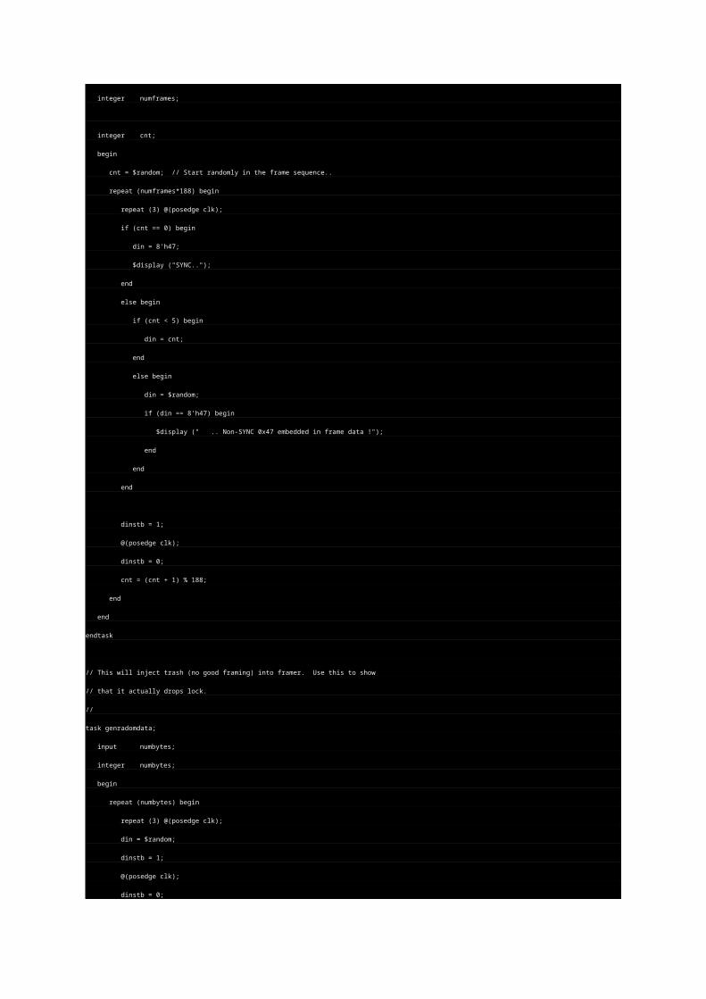
cnt = $random; // Start randomly in the frame sequence..
repeat (numframes*188) begin
repeat (3) @(posedge clk);
if (cnt == 0) begin
din = 8'h47;
$display ("SYNC..");
end
else begin
if (cnt < 5) begin
din = cnt;
end
else begin
din = $random;
if (din == 8'h47) begin
$display (" .. Non-SYNC 0x47 embedded in frame data !");
end
end
end
dinstb = 1;
@(posedge clk);
dinstb = 0;
cnt = (cnt + 1) % 188;
end
end
endtask
// This will inject trash (no good framing) into framer. Use this to show
// that it actually drops lock.
//
task genradomdata;
input numbytes;
integer numbytes;
begin
repeat (numbytes) begin
repeat (3) @(posedge clk);
din = $random;
dinstb = 1;
@(posedge clk);
dinstb = 0;
end
end
endtask
endmodule
// synopsys translate_on ...
/ Synchronous FIFO. 4 x 16 bit words.
//
module fifo (clk, rstp, din, writep, readp, dout, emptyp, fullp);
input clk;
input rstp;
input [15:0] din;
input readp;
input writep;
output [15:0] dout;
output emptyp;
output fullp;
// Defines sizes in terms of bits.
//
parameter DEPTH = 2, // 2 bits, e.g. 4 words in the FIFO.
MAX_COUNT = 2'b11; // topmost address in FIFO.
reg emptyp;
reg fullp;
// Registered output.
reg [15:0] dout;
// Define the FIFO pointers. A FIFO is essentially a circular queue.
//
reg [(DEPTH-1):0] tail;
reg [(DEPTH-1):0] head;
// Define the FIFO counter. Counts the number of entries in the FIFO which
// is how we figure out things like Empty and Full.
//
reg [(DEPTH-1):0] count;
// Define our regsiter bank. This is actually synthesizable!
//
reg [15:0] fifomem[0:MAX_COUNT];
// Dout is registered and gets the value that tail points to RIGHT NOW.
//
always @(posedge clk) begin
if (rstp == 1) begin
dout <= 16'h0000;
end
else begin
dout <= fifomem[tail];
end
end
// Update FIFO memory.
always @(posedge clk) begin
if (rstp == 1'b0 && writep == 1'b1 && fullp == 1'b0) begin
fifomem[head] <= din;
end
end
// Update the head register.
//
always @(posedge clk) begin
if (rstp == 1'b1) begin
head <= 2'b00;
end
else begin
if (writep == 1'b1 && fullp == 1'b0) begin
// WRITE
head <= head + 1;
end
end
end
// Update the tail register.
//
always @(posedge clk) begin
if (rstp == 1'b1) begin
tail <= 2'b00;
end
else begin
if (readp == 1'b1 && emptyp == 1'b0) begin
// READ
tail <= tail + 1;
end
end
end
// Update the count regsiter.
//
always @(posedge clk) begin
if (rstp == 1'b1) begin
count <= 2'b00;
end
else begin
case ({readp, writep})
2'b00: count <= count;
2'b01:
// WRITE
if (count != MAX_COUNT)
count <= count + 1;
2'b10:
// READ
if (count != 2'b00)
count <= count - 1;
2'b11:
// Concurrent read and write.. no change in count
count <= count;
endcase
end
end
// *** Update the flags
//
// First, update the empty flag.
//
always @(count) begin
if (count == 2'b00)
emptyp <= 1'b1;
else
emptyp <= 1'b0;
end
// Update the full flag
//
always @(count) begin
if (count == MAX_COUNT)
fullp <= 1'b1;
else
fullp <= 1'b0;
end
endmodule
// synopsys translate_off
`define TEST_FIFO
// synopsys translate_off
`ifdef TEST_FIFO
module test_fifo;
reg clk;
reg rstp;
reg [15:0] din;
reg readp;
reg writep;
wire [15:0] dout;
wire emptyp;
wire fullp;
reg [15:0] value;
fifo U1 (
.clk (clk),
.rstp (rstp),
.din (din),
.readp (readp),
.writep (writep),
.dout (dout),
.emptyp (emptyp),
.fullp (fullp)
);
task read_word;
begin
@(negedge clk);
readp = 1;
@(posedge clk) #5;
$display ("Read %0h from FIFO", dout);
readp = 0;
end
endtask
task write_word;
input [15:0] value;
begin
@(negedge clk);
din = value;
writep = 1;
@(posedge clk);
$display ("Write %0h to FIFO", din);
#5;
din = 16'hzzzz;
writep = 0;
end
endtask
initial begin
clk = 0;
forever begin
#10 clk = 1;
#10 clk = 0;
end
end
initial begin
$shm_open ("./fifo.shm");
$shm_probe (test_fifo, "AS");
//test1;
test2;
$shm_close;
$finish;
end
task test1;
begin
din = 16'hzzzz;
writep = 0;
readp = 0;
// Reset
rstp = 1;
#50;
rstp = 0;
#50;
// ** Write 3 values.
write_word (16'h1111);
write_word (16'h2222);
write_word (16'h3333);
// ** Read 2 values
read_word;
read_word;
// ** Write one more
write_word (16'h4444);
// ** Read a bunch of values
repeat (6) begin
read_word;
end
// *** Write a bunch more values
write_word (16'h0001);
write_word (16'h0002);
write_word (16'h0003);
write_word (16'h0004);
write_word (16'h0005);
write_word (16'h0006);
write_word (16'h0007);
write_word (16'h0008);
// ** Read a bunch of values
repeat (6) begin
read_word;
end
$display ("Done TEST1.");
end
endtask
// TEST2
//
// This test will operate the FIFO in an orderly manner the way it normally works.
// 2 threads are forked; a reader and a writer. The writer writes a counter to
// the FIFO and obeys the fullp flag and delays randomly. The reader likewise
// obeys the emptyp flag and reads at random intervals. The result should be that
// the reader reads the incrementing counter out of the FIFO. The empty/full flags
// should bounce around depending on the random delays. The writer repeats some
// fixed number of times and then terminates both threads and kills the sim.
//
task test2;
reg [15:0] writer_counter;
begin
writer_counter = 16'h0001;
din = 16'hzzzz;
writep = 0;
readp = 0;
// Reset
rstp = 1;
#50;
rstp = 0;
#50;
fork
// Writer
begin
repeat (500) begin
@(negedge clk);
if (fullp == 1'b0) begin
write_word (writer_counter);
#5;
writer_counter = writer_counter + 1;
end
else begin
$display ("WRITER is waiting..");
end
// Delay a random amount of time between 0ns and 100ns
#(50 + ($random % 50));
end
$display ("Done with WRITER fork..");
$finish;
end
// Reader
begin
forever begin
@(negedge clk);
if (emptyp == 1'b0) begin
read_word;
end
else begin
$display ("READER is waiting..");
end
// Delay a random amount of time between 0ns and 100ns
#(50 + ($random % 50));
end
end
join
end
endtask
always @(fullp)
$display ("fullp = %0b", fullp);
always @(emptyp)
$display ("emptyp = %0b", emptyp);
always @(U1.head)
$display ("head = %0h", U1.head);
always @(U1.tail)
$display ("tail = %0h", U1.tail);
endmodule`endif
///////////////////////////////////////////////////////////////////////////////
//This module is used to change the 50Mhz frequency to 20Mhz./////////////////
//Xiaoming,Chen,31,july,2002./////////////////////////////////////////////////
/////////////////////////////////////////////////////////////////////////////
`timescale 1ns/100ps
module frequency5x2(in,out,rst);
input in,rst;
output out;
reg out;
reg mid;
integer counter;
parameter delaytime=25;
always@(posedge rst )
begin
counter=0;
out=0;
mid=0;
end
always@(posedge in)
begin
if(counter==4)
begin
mid=~mid;
counter=0;
end
else
counter=counter+1;
end
always@(negedge in)
begin
if(counter==4)
begin
mid=~mid;
counter=0;
end
else
counter=counter+1;
end
always@(posedge mid )
begin
out=~out;
#delaytime out=~out;
end
always@(negedge mid)
begin
out=~out;
#delaytime out=~out;
end
endmodule
//////test module///////////////////////////////////////////////////////
//this module is used to test module frequency5x2.v////////////////////////
`timescale 1ns/100ps
module test;
reg clock,reset;
frequency5x2 t(clock,out,reset);
initial
begin
clock=0;
reset=0;
#10 reset=1;
end
always #10 clock=~clock;
endmodule //generate 20Mhz waveforme square wave
module full_adder(a,b,cin,out,carry);
input a,b,cin;
output out,carry;
reg out,carry;
reg t1,t2,t3;
always@
(a or b or cin)begin
out = a^b^cin;
t1 = a&cin;
t2 = b&cin;
t3 = a&b;
carry = t1|t2|t3;
end
endmodule ...
`include "half_adder_1.v"
module full_adder(a,b,cin,out,carry);
input a,b,cin;
output carry,out;
half_adder m1 (a,b,out1,carry1);
half_adder m2 (cin,out1,out,carry2);
or m3 (carry,carry1,carry2);
endmodule ...
//
// Behavioral Verilog for CRC16 and CRC32 for use in a testbench.
//
// The specific polynomials and conventions regarding bit-ordering etc.
// are specific to the Cable Modem DOCSIS protocol, but the general scheme
// should be reusable for other types of CRCs with some fiddling.
//
// This CRC code works for a specific type of network protocol, and it
// must do certain byte swappings, etc. You may need to play with it
// for your protocol. Also, make sure the polynomials are what you
// really want. This is obviously, not synthesizable - I just used this
// in a testbench at one point.
//
// These tasks are crude and rely on some global parameters. They should
// also read from a file, yada yada yada. It is probably better to do this
// with a PLI call, but here it is anyway..
//
// The test case includes a golden DOCSIS (Cable Modem) test message that
// was captured in a lab.
//
// tom coonan, 1999.
//
module test_gencrc;
// *** Buffer for the Golden Message ***
reg [7:0] test_packet[0:54];
// *** Global parameter block for the CRC32 calculator.
//
parameter CRC32_POLY = 32'h04C11DB7;
reg [ 7:0] crc32_packet[0:255];
integer crc32_length;
reg [31:0] crc32_result;
// *** Global parameter block for the CRC16 calculator.
//
parameter CRC16_POLY = 16'h1020;
reg [ 7:0] crc16_packet[0:255];
integer crc16_length;
reg [15:0] crc16_result;
`define TEST_GENCRC
`ifdef TEST_GENCRC
// Call the main test task and then quit.
//
initial begin
main_test;
$finish;
end
`endif
// ****************************************************************
// *
// * GOLDEN MESSAGE
// *
// * The golden message is a DOCSIS frame that was captured off
// * the Broadcom reference design. It is a MAP message. It
// * includes a HCS (crc 16) and a CRC32.
// *
// *
// ****************************************************************
//
task initialize_test_packet;
begin
test_packet[00] = 8'hC2; // FC. HCS coverage starts here.
test_packet[01] = 8'h00; // MACPARAM
test_packet[02] = 8'h00; // MAC LEN
test_packet[03] = 8'h30; // MAC LEN. HCS Coverage includes this byte and ends here.
test_packet[04] = 8'hF2; // CRC16 (also known as HCS)
test_packet[05] = 8'hCF; // CRC16 cont..
test_packet[06] = 8'h01; // Start of the IEEE payload. CRC32 covererage starts here. This is the DA field
test_packet[07] = 8'hE0; // DA field cont..
test_packet[08] = 8'h2F; // DA field cont..
test_packet[09] = 8'h00; // DA field cont..
test_packet[10] = 8'h00; // DA field cont..
test_packet[11] = 8'h01; // DA field cont..
test_packet[12] = 8'h00; // SA field
test_packet[13] = 8'h80; // SA field cont..
test_packet[14] = 8'h42; // SA field cont..
test_packet[15] = 8'h42; // SA field cont..
test_packet[16] = 8'h20; // SA field cont..
test_packet[17] = 8'h9E; // SA field cont..
test_packet[18] = 8'h00; // IEEE LEN field
test_packet[19] = 8'h1E; // IEEE LEN field cont.
test_packet[20] = 8'h00; // LLC field.
test_packet[21] = 8'h00; // LLC field cont...
test_packet[22] = 8'h03; // LLC field cont...
test_packet[23] = 8'h01; // LLC field cont...
test_packet[24] = 8'h03; // LLC field cont... This is also the TYPE, which indicates MAP.
test_packet[25] = 8'h00; // LLC field cont...
test_packet[26] = 8'h01; // Start of MAP message payload.
test_packet[27] = 8'h01; // MAP message payload..
test_packet[28] = 8'h02; // MAP message payload..
test_packet[29] = 8'h00; // MAP message payload..
test_packet[30] = 8'h00; // MAP message payload..
test_packet[31] = 8'h18; // MAP message payload..
test_packet[32] = 8'hAA; // MAP message payload..
test_packet[33] = 8'h58; // MAP message payload..
test_packet[34] = 8'h00; // MAP message payload..
test_packet[35] = 8'h18; // MAP message payload..
test_packet[36] = 8'hA8; // MAP message payload..
test_packet[37] = 8'hA0; // MAP message payload..
test_packet[38] = 8'h02; // MAP message payload..
test_packet[39] = 8'h03; // MAP message payload..
test_packet[40] = 8'h03; // MAP message payload..
test_packet[41] = 8'h08; // MAP message payload..
test_packet[42] = 8'hFF; // MAP message payload..
test_packet[43] = 8'hFC; // MAP message payload..
test_packet[44] = 8'h40; // MAP message payload..
test_packet[45] = 8'h00; // MAP message payload..
test_packet[46] = 8'h00; // MAP message payload..
test_packet[47] = 8'h01; // MAP message payload..
test_packet[48] = 8'hC0; // MAP message payload..
test_packet[49] = 8'h14; // Last byte of MAP payload, last byte covered by CRC32.
test_packet[50] = 8'hDD; // CRC32 Starts here
test_packet[51] = 8'hBF; // CRC32 cont..
test_packet[52] = 8'hC1; // CRC32 cont..
test_packet[53] = 8'h2E; // Last byte of CRC32, last byte of DOCSIS.
end
endtask
// *************************************************************************
// *
// * Main test task.
// *
// * Use our primary "golden packet". Copy into the generic global
// * variables that the low-level 'gencrc16' and 'gencrc32' tasks use.
// * Comare against the expected values and report SUCCESS or FAILURE.
// *
// *************************************************************************
//
task main_test;
integer i, j;
integer num_errors;
reg [15:0] crc16_expected;
reg [31:0] crc32_expected;
begin
num_errors = 0;
// Initialize the Golden Message!
//
initialize_test_packet;
// **** TEST CRC16
//
$display ("Testing CRC16:");
//
// Copy golden test_packet into the main crc16 buffer..
for (i=0; i<4; i=i+1) begin
crc16_packet[i] = test_packet[i];
end
crc16_expected = {test_packet[4], test_packet[5]};
crc16_length = 4; // Must tell test function the length
gencrc16; // Call main test function
$display (" Actual crc16_result = %h, Expected = %h", crc16_result, crc16_expected);
if (crc16_result == crc16_expected) begin
$display (" Success.");
end
else begin
$display (" ERROR!!!");
num_errors = num_errors + 1;
end
// **** TEST CRC16
//
$display ("Testing CRC32:");
j = 0;
for (i=6; i<50; i=i+1) begin
crc32_packet[j] = test_packet[i];
j = j + 1;
end
crc32_expected = {test_packet[50], test_packet[51], test_packet[52], test_packet[53]};
crc32_length = 44;
gencrc32;
$display (" Actual crc32_result = %h, Expected = %h", crc32_result, crc32_expected);
if (crc32_result == crc32_expected) begin
$display (" Success.");
end
else begin
$display (" ERROR!!!");
num_errors = num_errors + 1;
end
$display ("\nDone. %0d Errors.", num_errors);
$display ("\n");
end
endtask
// ****************************************************************
// *
// * Main working CRC tasks are: gencrc16, gencrc32.
// *
// * These tasks rely on some globals (see front of program).
// *
// ****************************************************************
// Generate a (DOCSIS) CRC16.
//
// Uses the GLOBAL variables:
//
// Globals referenced:
// parameter CRC16_POLY = 16'h1020;
// reg [ 7:0] crc16_packet[0:255];
// integer crc16_length;
//
// Globals modified:
// reg [15:0] crc16_result;
//
task gencrc16;
integer byte, bit;
reg msb;
reg [7:0] current_byte;
reg [15:0] temp;
begin
crc16_result = 16'hffff;
for (byte = 0; byte < crc16_length; byte = byte + 1) begin
current_byte = crc16_packet[byte];
for (bit = 0; bit < 8; bit = bit + 1) begin
msb = crc16_result[15];
crc16_result = crc16_result << 1;
if (msb != current_byte[bit]) begin

crc16_result = crc16_result ^ CRC16_POLY;
crc16_result[0] = 1;
end
end
end
// Last step is to "mirror" every bit, swap the 2 bytes, and then complement each bit.
//
// Mirror:
for (bit = 0; bit < 16; bit = bit + 1)
temp[15-bit] = crc16_result[bit];
// Swap and Complement:
crc16_result = ~{temp[7:0], temp[15:8]};
end
endtask
// Generate a (DOCSIS) CRC32.
//
// Uses the GLOBAL variables:
//
// Globals referenced:
// parameter CRC32_POLY = 32'h04C11DB7;
// reg [ 7:0] crc32_packet[0:255];
// integer crc32_length;
//
// Globals modified:
// reg [31:0] crc32_result;
//
task gencrc32;
integer byte, bit;
reg msb;
reg [7:0] current_byte;
reg [31:0] temp;
begin
crc32_result = 32'hffffffff;
for (byte = 0; byte < crc32_length; byte = byte + 1) begin
current_byte = crc32_packet[byte];
for (bit = 0; bit < 8; bit = bit + 1) begin
msb = crc32_result[31];
crc32_result = crc32_result << 1;
if (msb != current_byte[bit]) begin
crc32_result = crc32_result ^ CRC32_POLY;
crc32_result[0] = 1;
end
end
end
// Last step is to "mirror" every bit, swap the 4 bytes, and then complement each bit.
//
// Mirror:
for (bit = 0; bit < 32; bit = bit + 1)
temp[31-bit] = crc32_result[bit];
// Swap and Complement:
crc32_result = ~{temp[7:0], temp[15:8], temp[23:16], temp[31:24]};
end
endtask
endmodule
module half_adder(a,b,out,carry);
input a,b;
output out,carry;
assign {carry,out}=a+b;endmodule ...
module half_adder(a,b,out,carry);
input a,b;
output out,carry;
assign out=a^b;
assign carry=a&b;
endmodule ...
module half_adder(a,b,out,carry);
input a,b;
output out,carry;
xor n1(out,a,b);
and n2(carry,a,b);endmodule ...
module lead_8bits_adder(a,b,cin,sum,cout);
input [7:0]a,b;
input cin;
output [7:0]sum;
output cout;
reg [7:0]sum;
reg cout;
always@(a or b or cin)
begin
sum[0]=(a[0]&b[0])| (a[0]| b[0])&cin;
sum[1]=(a[1]&b[1])| (a[1]| b[1])&((a[0]^b[0])^cin);
sum[2]=(a[2]&b[2])| (a[2]| b[2])&((a[1]^b[1])^(a[0]^b[0])^cin);
sum[3]=(a[3]&b[3])| (a[3]| b[3])&((a[2]^b[2])^(a[1]^b[1])^(a[0]^b[0])^cin);
sum[4]=(a[4]&b[4])| (a[4]| b[4])&((a[3]^b[3])^(a[2]^b[2])^(a[1]^b[1])^(a[0]^b[0])^cin);
sum[5]=(a[5]&b[5])| (a[5]| b[5])&((a[4]^b[4])^(a[3]^b[3])^(a[2]^b[2])^(a[1]^b[1])^(a[0]^b[0])^cin);
sum[6]=(a[6]&b[6])| (a[6]| b[6])&((a[5]^b[5])^(a[4]^b[4])^(a[3]^b[3])^(a[2]^b[2])^(a[1]^b[1])^(a[0]^b[0])^cin);
sum[7]=(a[7]&b[7])| (a[7]| b[7])&((a[6]^b[6])^(a[5]^b[5])^(a[4]^b[4])^(a[3]^b[3])^(a[2]^b[2])^(a[1]^b[1])^(a[0]^b[0])^cin);
cout=(a[7]^b[7])^(a[6]^b[6])^(a[5]^b[5])^(a[4]^b[4])^(a[3]^b[3])^(a[2]^b[2])^(a[1]^b[1])^(a[0]^b[0])^cin;
end
endmodule
module lead_8bits_adder(a,b,cin,sum,cout);
input [7:0]a,b;
input cin;
output [7:0]sum;
output cout;
reg [7:0]sum;
reg cout;
always@(a or b or cin)
begin
sum[0]=(a[0]&b[0])| (a[0]| b[0])&cin;
sum[1]=(a[1]&b[1])| (a[1]| b[1])&(a[0]^b[0]^cin);
sum[2]=(a[2]&b[2])| (a[2]| b[2])&(a[1]^b[1]^a[0]^b[0]^cin);
sum[3]=(a[3]&b[3])| (a[3]| b[3])&(a[2]^b[2]^a[1]^b[1]^a[0]^b[0]^cin);
sum[4]=(a[4]&b[4])| (a[4]| b[4])&(a[3]^b[3]^a[2]^b[2]^a[1]^b[1]^a[0]^b[0]^cin);
sum[5]=(a[5]&b[5])| (a[5]| b[5])&(a[4]^b[4]^a[3]^b[3]^a[2]^b[2]^a[1]^b[1]^a[0]^b[0]^cin);
sum[6]=(a[6]&b[6])| (a[6]| b[6])&(a[5]^b[5]^a[4]^b[4]^a[3]^b[3]^a[2]^b[2]^a[1]^b[1]^a[0]^b[0]^cin);
sum[7]=(a[7]&b[7])| (a[7]| b[7])&(a[6]^b[6]^a[5]^b[5]^a[4]^b[4]^a[3]^b[3]^a[2]^b[2]^a[1]^b[1]^a[0]^b[0]^cin);
cout=a[7]^b[7]^a[6]^b[6]^a[5]^b[5]^a[4]^b[4]^a[3]^b[3]^a[2]^b[2]^a[1]^b[1]^a[0]^b[0]^cin;
end
endmodule ...
module mult16(clk,resetb,start,done,ain,bin,yout);
parameter N=16;
input clk;
input resetb;
input start;
input [N-1:0] ain;
input [N-1:0] bin;
output [2*N-1:0] yout;
output done;
reg [2*N-1:0] a;
reg [N-1:0] b;
reg [2*N-1:0] yout;
reg done;
always@(posedge clk or negedge resetb)
begin
if(~resetb)
begin
a<=0;
b<=0;
yout<=0;
done<=1'b1;
end
else
begin
if(start)
begin
a<=ain;
b<=bin;
yout<=0;
done<=0;
end
else
begin
if(~done)
begin
if(b!=0)
begin
if(b[0])yout<=yout+a;
b<=b>>1;
a<=a<<1;
end
else
done<=1'b1;
end
end
end
end
endmodule
// **** Here's a simple, sequential multiplier. Very simple, unsigned..
// Not very well tested, play with testbench, use at your own risk, blah blah blah..
//
//
// Unsigned 16-bit multiply (multiply two 16-bit inputs to get a 32-bit output)
//
// Present data and assert start synchronous with clk.
// Assert start for ONLY one cycle.
// Wait N cycles for answer (at most). Answer will remain stable until next start.
// You may use DONE signal as handshake.
//
// Written by tom coonan
//
module mult16 (clk, resetb, start, done, ain, bin, yout);
parameter N = 16;
input clk;
input resetb;
input start; // Register the ain and bin inputs (they can change afterwards)
input [N-1:0] ain;
input [N-1:0] bin;
output [2*N-1:0]yout;
output done;
reg [2*N-1:0] a;
reg [N-1:0] b;
reg [2*N-1:0] yout;
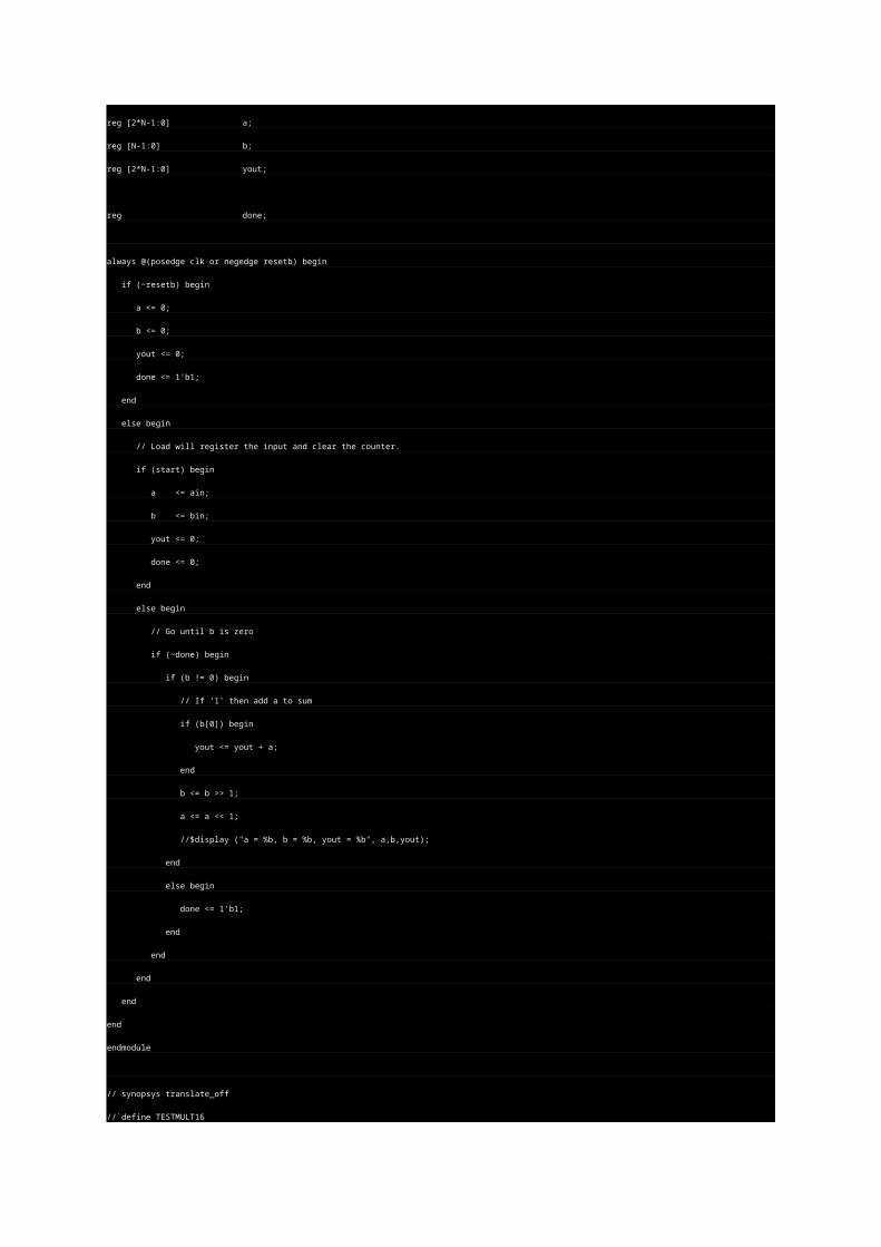
reg done;
always @(posedge clk or negedge resetb) begin
if (~resetb) begin
a <= 0;
b <= 0;
yout <= 0;
done <= 1'b1;
end
else begin
// Load will register the input and clear the counter.
if (start) begin
a <= ain;
b <= bin;
yout <= 0;
done <= 0;
end
else begin
// Go until b is zero
if (~done) begin
if (b != 0) begin
// If '1' then add a to sum
if (b[0]) begin
yout <= yout + a;
end
b <= b >> 1;
a <= a << 1;
//$display ("a = %b, b = %b, yout = %b", a,b,yout);
end
else begin
done <= 1'b1;
end
end
end
end
end
endmodule
// synopsys translate_off
//`define TESTMULT16
`ifdef TESTMULT16
module testmult16;
reg clk, resetb, start;
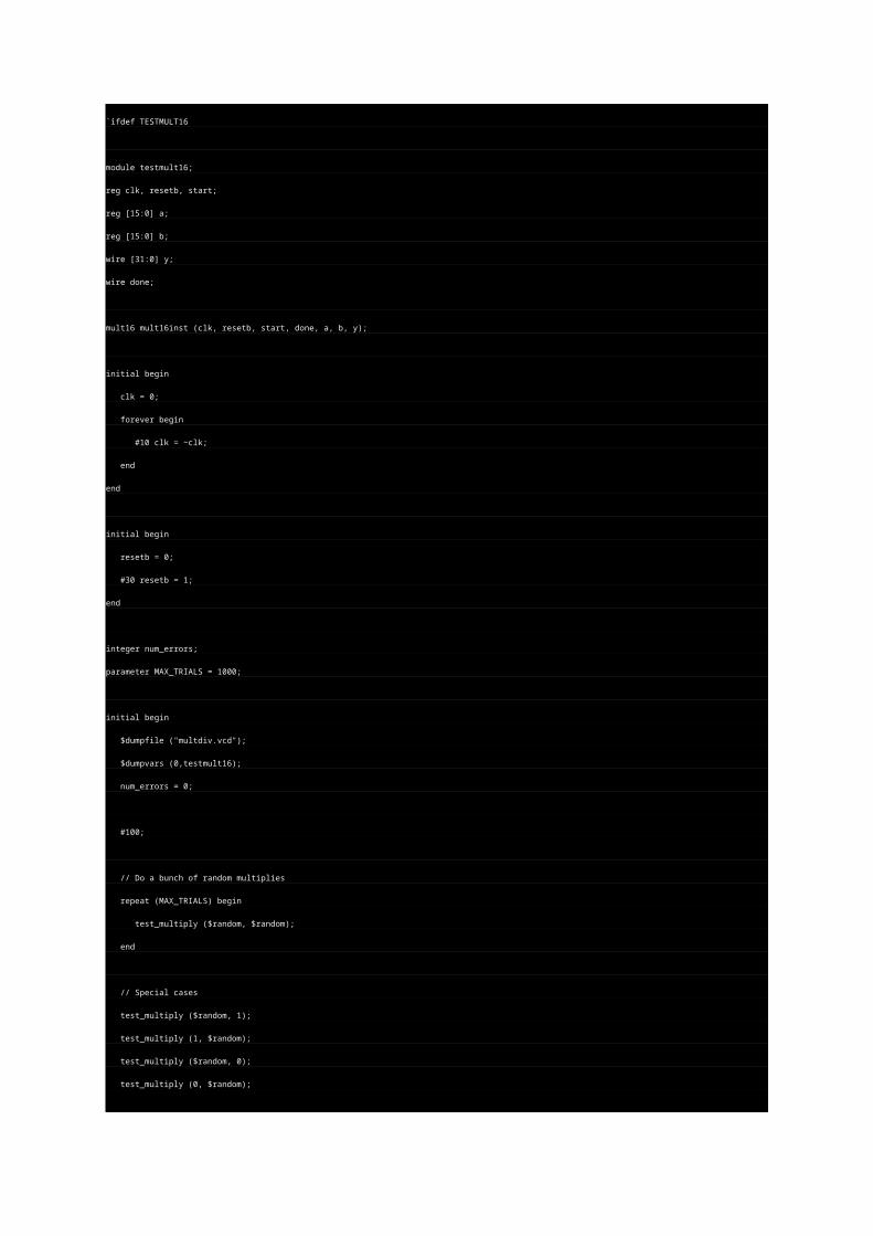
reg [15:0] a;
reg [15:0] b;
wire [31:0] y;
wire done;
mult16 mult16inst (clk, resetb, start, done, a, b, y);
initial begin
clk = 0;
forever begin
#10 clk = ~clk;
end
end
initial begin
resetb = 0;
#30 resetb = 1;
end
integer num_errors;
parameter MAX_TRIALS = 1000;
initial begin
$dumpfile ("multdiv.vcd");
$dumpvars (0,testmult16);
num_errors = 0;
#100;
// Do a bunch of random multiplies
repeat (MAX_TRIALS) begin
test_multiply ($random, $random);
end
// Special cases
test_multiply ($random, 1);
test_multiply (1, $random);
test_multiply ($random, 0);
test_multiply (0, $random);
$display ("Done. %0d Errors", num_errors);
#800;
$finish;
end
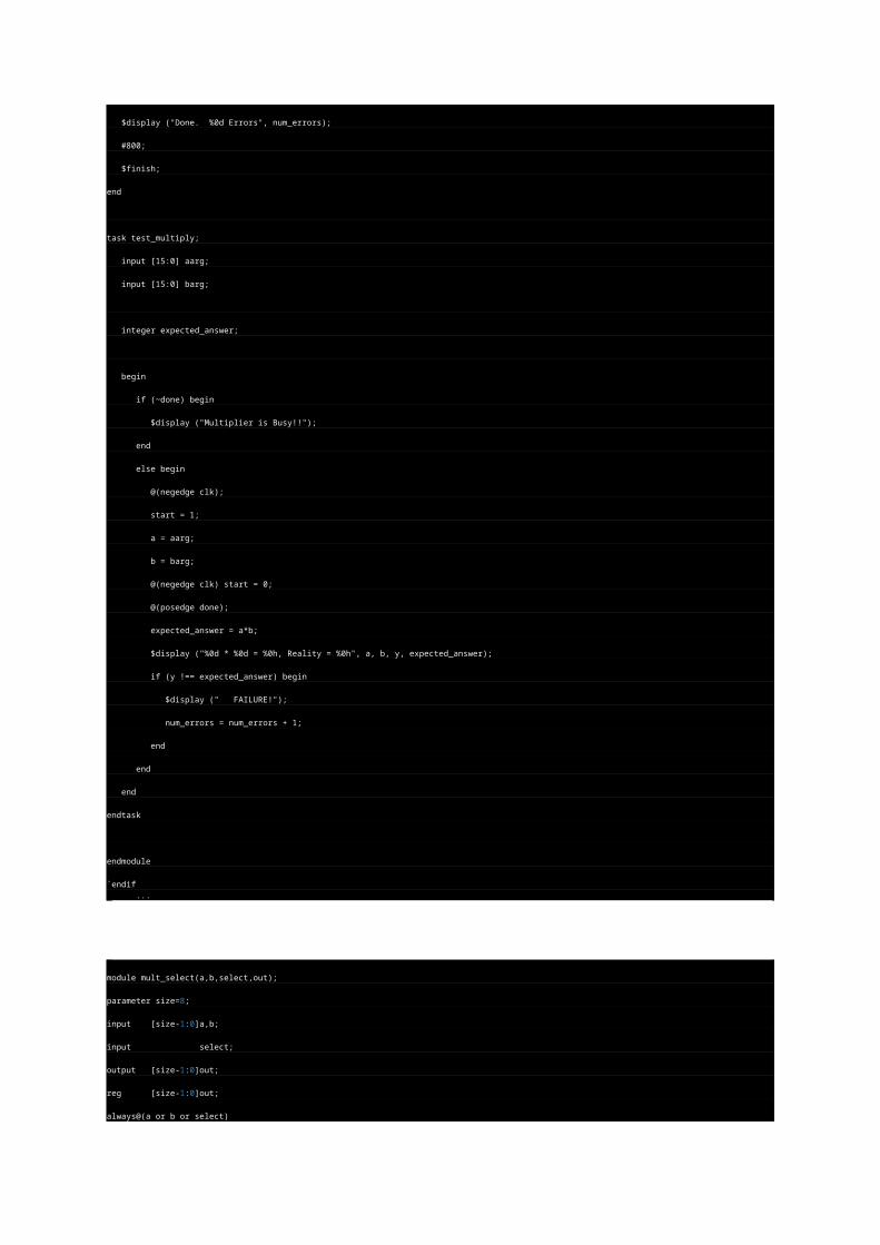
task test_multiply;
input [15:0] aarg;
input [15:0] barg;
integer expected_answer;
begin
if (~done) begin
$display ("Multiplier is Busy!!");
end
else begin
@(negedge clk);
start = 1;
a = aarg;
b = barg;
@(negedge clk) start = 0;
@(posedge done);
expected_answer = a*b;
$display ("%0d * %0d = %0h, Reality = %0h", a, b, y, expected_answer);
if (y !== expected_answer) begin
$display (" FAILURE!");
num_errors = num_errors + 1;
end
end
end
endtask
endmodule
`endif ...
module mult_select(a,b,select,out);
parameter size=8;
input [size-1:0]a,b;
input select;
output [size-1:0]out;
reg [size-1:0]out;
always@(a or b or select)
begin
if(select)
out=a;
else
out=b;
end
endmodule ...
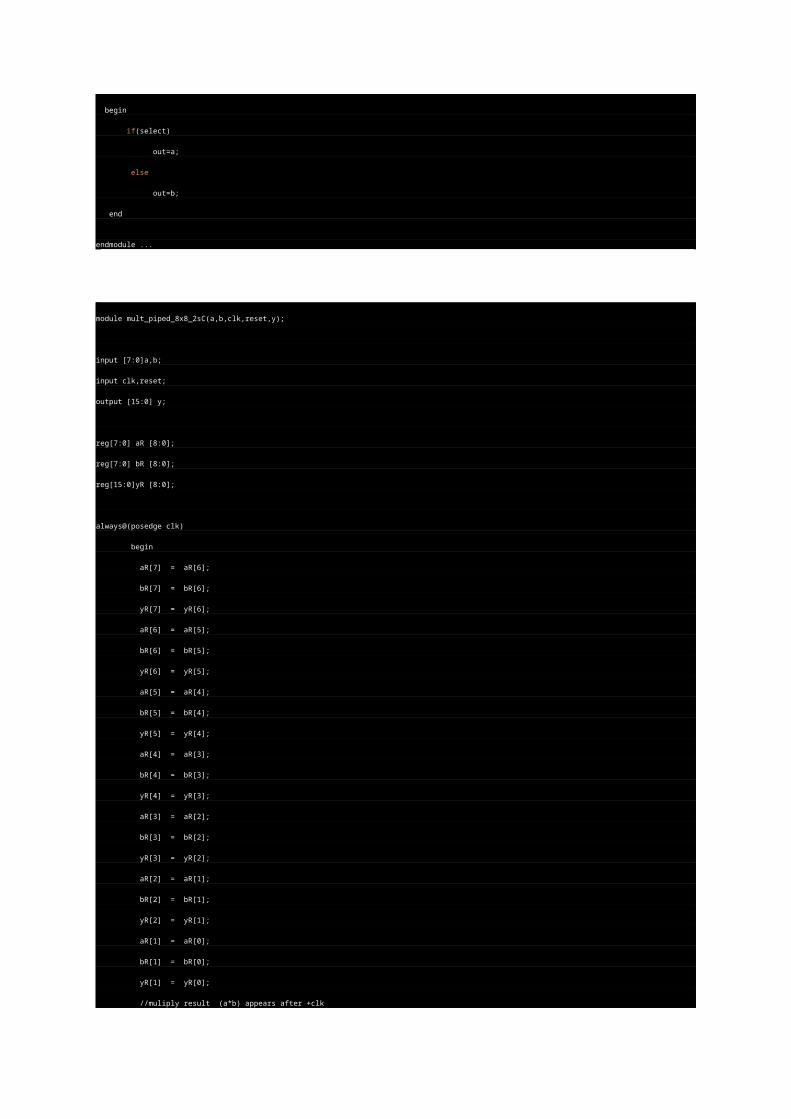
module mult_piped_8x8_2sC(a,b,clk,reset,y);
input [7:0]a,b;
input clk,reset;
output [15:0] y;
reg[7:0] aR [8:0];
reg[7:0] bR [8:0];
reg[15:0]yR [8:0];
always@(posedge clk)
begin
aR[7] = aR[6];
bR[7] = bR[6];
yR[7] = yR[6];
aR[6] = aR[5];
bR[6] = bR[5];
yR[6] = yR[5];
aR[5] = aR[4];
bR[5] = bR[4];
yR[5] = yR[4];
aR[4] = aR[3];
bR[4] = bR[3];
yR[4] = yR[3];
aR[3] = aR[2];
bR[3] = bR[2];
yR[3] = yR[2];
aR[2] = aR[1];
bR[2] = bR[1];
yR[2] = yR[1];
aR[1] = aR[0];
bR[1] = bR[0];
yR[1] = yR[0];
//muliply result (a*b) appears after +clk
aR[0] =a;
bR[0] =b;
yR[0] =multiply_8x8_2sC (aR[0],bR[0]);
end
function[15:0] multiply_8x8_2sC;
input [7:0] a,b;
reg [7:0] a_mag,b_mag;
reg [14:0] Y_mag;
reg [14:0] Y_neg;
begin
case (a[7])
0:a_mag = a[6:0];
1:a_mag =128-a[6:0];
endcase
case (b[7])
0:b_mag = b[6:0];
1:b_mag =128-b[6:0];
endcase
Y_mag=a_mag*b_mag;
if((a[7]^b[7])&(Y_mag!=0))
begin
Y_neg=32768-Y_mag[13:0];
multiply_8x8_2sC={1'b1,Y_neg};
end
else
multiply_8x8_2sC=Y_mag;
end
endfunction
assign y=yR[7];
endmodule
`include "oc8051_timescale.v"
// synopsys translate_on
`include "oc8051_defines.v"
module oc8051_alu_src1_sel (sel, immediate, acc, ram, ext, des);
//
// sel (in) select signals (from decoder, delayd one clock) [oc8051_decoder.src_sel1 -r]
// immediate (in) immediate operand [oc8051_immediate_sel.out1]
// acc (in) accomulator [oc8051_acc.data_out]
// ram (in) ram input [oc8051_ram_sel.out_data]
// ext (in) external ram input [pin]
// des (out) output (alu sorce 1) [oc8051_alu.src1]
//
input [1:0] sel; input [7:0] immediate, acc, ram, ext;
output [7:0] des;
reg [7:0] des;
always @(sel or immediate or acc or ram or ext)
begin
case (sel)
`OC8051_ASS_RAM: des= ram;
`OC8051_ASS_ACC: des= acc;
`OC8051_ASS_XRAM: des= ext;
`OC8051_ASS_IMM: des= immediate;
default: des= 2'bxx;
endcase
end
endmodule
module mux8x8(a,b,out);
parameter size=8,longsize=16;
input [size-1:0]a,b;
output [longsize-1:0]out;
reg [size-1:0]opa,opb;
reg [longsize:1]result ;
reg [size:0]n;
reg [longsize-1:0]out;
always @(a or b)
begin
n=0;
out=0;
for(n=1;n<=size;n=n+1)
if(opb[n])
result=result+(opa<<(n-1));
out=result;
endendmodule
/ RANDOM Number generator (hardware friendly)
//
// LFSR Register for a maximal length P/N sequence of 2^32:
//
// Taken from XILINX App Note XAPP 052.
//
// Taps for 32-bit sequence are at:
// 31,21,1,0
//
// Feed XNOR of tapped bits into LSB of left-shifted register.
//
// Ideas for testing:
//
// For example, for the 8-bit sequence,
// 1. myrand FFF >! myrand.out
//
// This write 4096 numbers to the file. The 256 element sequence should
// repeat 16 times. Confirm this by grepping for random values.
//
// 2. grep -c 0000001A myrand.out
//
// Should print '16'. Do this for as many values as you can think of.
// Searching for 000000FF should yield ZERO, however.
// For the 32-bit seqence, you don't want to generate 4 billion values. Instead,
// generate as many as you can (e.g. myrand 000FFFFF, which will generate 1 million).
// Open the file in an editor, randomly pick values, and then do the grep for that
// same value. Grep should print exactly '1' for each such example.
//
#include <stdio.h>
// Generate a constant array specifying where the TAPs are.
// Fill this in from some LFSR Maximal Sequence table, such
// as is found in the XILINX app note.
//
// This particular program is limitied to 32-bit sequences since we are
// using simple unsigned long int variable, but can be extended. The XAPP
// Note's table goes up to 168 bits.
//
// TAPS. Select the one you want. See XAPP 052 for more possibilities.
//
const int taps[] = {31,21,1,0, -1}; // TAPS For 32-bit sequence. (Use -1 to end list)
//const int taps[] = {7,5,4,3, -1}; // TAPS For 8-bit sequence. (Use -1 to end list)
//const int taps[] = {3,2, -1}; // TAPS For 4-bit sequence. (Use -1 to end list)
// Indicate width. Specify 32 if you want 2^32 - 1 Maximal Length Sequence.
#define WIDTH 32
// XILINX App Note says to use zero. It says that the All-1s value is the LOCK-up value
// and should never be reached.
//
#define SEED 0
int main (int argc, char *argv[])
{
unsigned long int x;
int i, j;
unsigned long int masks[32];
unsigned long int feedback;
unsigned long int n_points;
unsigned long int width;
if (argc == 1) {
printf ("\n");
printf ("Usage:\n");
printf (" myrand <# points in hex>\n");
printf ("\n");
printf ("Example:\n");
printf (" myrand FFF ; Generate 4096 points\n");
printf ("\n");
printf ("Notes:\n");
printf (" At this time, you must change source code for different lengths..\n");
printf ("\n");
printf ("Currently, Taps are:\n");
for (j = 0; taps[j] != -1; j++) {
printf ("%ld ", taps[j]);
}
printf ("\n");
return 1;
}
// Use command line argument to specify how many points.
//
n_points = 0;
sscanf (argv[1], "%lx", &n_points);
if (n_points == 0) {
printf ("\nERROR: Must specify (in hex) how many points!\n");
return 1;
}
// Generate the bit masks. Generate all 32.
//
for (i = 0; i < 32; i++) {
masks[i] = 1 << i;
}
width = (1 << WIDTH) - 1;
//printf ("width = %lx\n", width);
x = SEED;
// For the number of points requested..
while (n_points--) {
// Based on the taps array, generate each XOR term. Remember, -1 signifies the end.
feedback = 0;
for (j = 0; taps[j] != -1; j++) {
// FOR Debug:
// printf ("x = %08lx, taps[j] = %ld, masks[taps[j]] = %08lx, (x & masks[taps[j]]) = %l08x\n",
// x, taps[j], masks[taps[j]], (x & masks[taps[j]]) );
feedback ^= (x & masks[taps[j]]) ? 0x00000001 : 0x00000000;
}
// Do the XNOR (so, just complement BIT 0 of our feedback term)
feedback ^= 0x00000001;
// In hardware, this'll be more straight-forward, e.g. for the 32-bit case:
// assign feedback = ~^{x[31],x[21],x[1],x[0]};
// always @(posedge clk) ... x <= {x[30:0], feedback};
//
// Shift X to the left. We'll OR in our feedback term in a moment.
x <<= 1;
// OR feedback bit into bit 0.
x |= feedback;
x &= width;
// printf ("%08lX %08lX\n", feedback, x);
printf ("%08lX\n", x);
}
}
/*
Here's the Verilog for reference...
// Random Number Generator, 8-bit
//
// See companion program myrand.c
//
// (to verify, do the GREP trick described in myrand.c on verilog.out)
//
module myrand;
reg clk, reset;
reg [7:0] x;
wire feedback;
// Use TAPS table from XACT 052 to make whatever length sequence you need.
assign feedback = ~^{x[7],x[5],x[4],x[3]};
// Shift and input feedback term. That's it!
always @(posedge clk) begin
if (reset) x <= 0;
else x <= {x[6:0], feedback};
end
// remaining code just testbench...
initial begin
clk = 0;
forever begin
#10 clk = ~clk;
end
end
initial begin
reset = 0;
#1 reset = 1;
#35 reset = 0;
end
initial begin
@(negedge reset);
repeat (1024) begin
@(posedge clk) #1;
$display ("%h", x);
end
$finish;
end
endmodule
NCO Demo (Numerically controlled Oscillator).
//
// One type of NCO is based on the idea of a continuously wrapping modulo
// counter. The NCO is a programmable modulo counter. For example, if
// the MOD input is set to 10, then it'll count 0,1,2,3,4,5,6,7,8,9,0,1,2 etc.
// The STEP input is continuously added to the modulo counter. What's important
// is not the counter value itself, but the number of times it "wraps". If
// you do the math, the counter will wrap at a rate of F*S/M (F is the system
// clock frequency, S is the step input, and M is the modulo). Every wrap
// occurance is a little pulse. The pulse output could be used as the clock itself
// except that it may have a very small duty cycle. Instead, take the WRAP
// pulse signal and use it to increment a TICKS counter. The TICKS counter will
// then count at the programmed frequency.
//
// The TICK counter could be used in itself for, say, a TDMA slot counter. Any
// number of TICKS LSB bits can be thrown away to "reduce jitter" but also
// reduce the rate. This NCO has a little MASK input and an internal OR gate
// so you can pick off whichever TICKS bits you wish for your final FOUT output.
//
// In an open-loop mode, you program your Modulo and Step inputs and you are done.
// If you are tracking some other reference (e.g. like in a PLL style circuit) you
// would somehow control STEP via some sort of "phase detector" and loop filter.
// None of this is shown here.
//
// Anyway, this is just the guts of the NCO, which can be applied in many, many
// ways.
//
// Oh.. And this NCO seems to be off by a small percentage..?!.. I'm not sure
// why. It may be the circuit or the testbench. Let me know if you play with it
// and find out. My application is closed-loop, so, I'm not highly motivated
// to figure it out.
//
// Written by tom coonan
//
module nco (
clk,
resetb,
step, // Step input is continuously added to the modulo counter
mod, // modulo
mask, // Mask is ANDed with ticks and gen ORed to produce fout
ticks, // Tick counter output
fout // Output.
);
parameter W_ACCUM = 24; // Width of the Accumulator
parameter W_TICK = 8; // Width of the Tick counter.
parameter W_STEP = 24;
parameter W_MOD = 24;
input clk;
input resetb;
input [W_STEP-1:0] step;
input [W_MOD-1:0] mod;
input [W_TICK-1:0] mask;
output [W_TICK-1:0] ticks;
output fout;
// Registered outputs
// Internals
reg [W_ACCUM-1:0] accum, accum_in;
reg [W_TICK-1:0] ticks;
// *** Modulo Counter ***
// Registered outputs
reg wrap;
wire [W_ACCUM-1:0] sum = accum + step;
wire [W_ACCUM-1:0] rem = sum - mod;
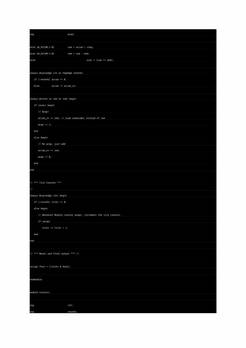
wire over = (sum >= mod);
always @(posedge clk or negedge resetb)
if (~resetb) accum <= 0;
else accum <= accum_in;
always @(over or rem or sum) begin
if (over) begin
// Wrap!
accum_in <= rem; // load remainder instead of sum
wrap <= 1;
end
else begin
// No wrap, just add
accum_in <= sum;
wrap <= 0;
end
end
// *** Tick Counter ***
//
always @(posedge clk) begin
if (~resetb) ticks <= 0;
else begin
// Whenever Modulo counter wraps, increment the tick counter.
if (wrap)
ticks <= ticks + 1;
end
end
// *** Masks and final output *** //
assign fout = |(ticks & mask);
endmodule
module ncotest;
reg clk;
reg resetb;
reg [23:0] step;
reg [23:0] mod;
reg [7:0] mask;
wire fout;
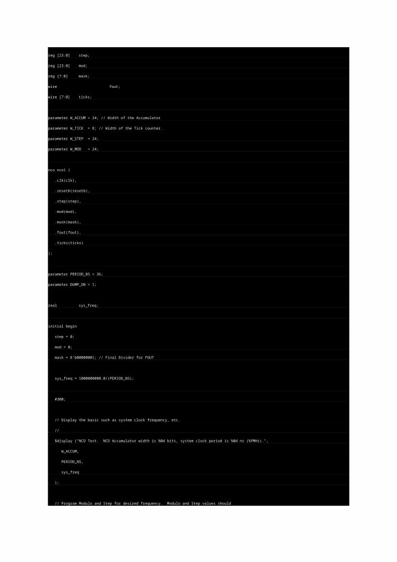
wire [7:0] ticks;
parameter W_ACCUM = 24; // Width of the Accumulator
parameter W_TICK = 8; // Width of the Tick counter.
parameter W_STEP = 24;
parameter W_MOD = 24;
nco nco1 (
.clk(clk),
.resetb(resetb),
.step(step),
.mod(mod),
.mask(mask),
.fout(fout),
.ticks(ticks)
);
parameter PERIOD_NS = 36;
parameter DUMP_ON = 1;
real sys_freq;
initial begin
step = 0;
mod = 0;
mask = 8'b00000001; // Final Divider for FOUT
sys_freq = 1000000000.0/(PERIOD_NS);
#300;
// Display the basic such as system clock frequency, etc.
//
$display ("NCO Test. NCO Accumulator width is %0d bits, system clock period is %0d ns (%fMHz).",
W_ACCUM,
PERIOD_NS,
sys_freq
);
// Program Modulo and Step for desired frequency. Modulo and Step values should
// not be divisible by each other (I'm not mathematically strong enough to
// justify this...). Find the ratio of S/M, integerize it, and reduce to lowest
// common divisors. Then, multiply up by a big power of 2 so we can get some
// resolution on the NCO.
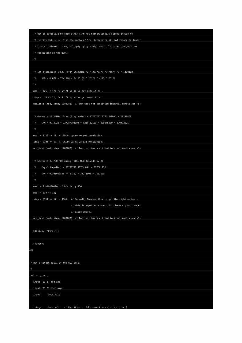
//
// Let's generate 1Mhz, Fsys*(Step/Mod)/2 = 27777777.777*(S/M)/2 = 1000000
// S/M = 0.072 = 72/1000 = 9/125 (9 * 2^12) / (125 * 2^12)
//
mod = 125 << 12; // Shift up so we get resolution..
step = 9 << 12; // Shift up so we get resolution..
nco_test (mod, step, 1000000); // Run test for specified interval (units are NS)
// Generate 10.24MHz: Fsys*(Step/Mod)/2 = 27777777.777*(S/M)/2 = 10240000
// S/M = 0.73728 = 73728/100000 = 9216/12500 = 4608/6250 = 2304/3125
//
mod = 3125 << 10; // Shift up so we get resolution..
step = 2304 << 10; // Shift up so we get resolution..
nco_test (mod, step, 1000000); // Run test for specified interval (units are NS)
// Generate 32.768 KHz using TICKS MSB (divide by 8):
// Fsys*(Step/Mod) = 27777777.777*(S/M) = 32768*256
// S/M = 0.301989888 =~ 0.302 = 302/1000 = 151/500
//
mask = 8'b10000000; // Divide by 256
mod = 500 << 12;
step = (151 << 12) - 9566; // Manually Tweaked this to get the right number..
// this is expected since didn't have a good integer
// ratio above..
nco_test (mod, step, 1000000); // Run test for specified interval (units are NS)
$display ("Done.");
$finish;
end
// Run a single trial of the NCO test.
//
task nco_test;
input [23:0] mod_arg;
input [23:0] step_arg;
input interval;
integer interval; // Use $time.. Make sure timescale is correct!
integer start_time;
integer fout_edges;
begin
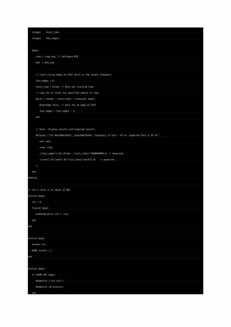
step = step_arg; // Configure NCO
mod = mod_arg;
// Count rising edges on FOUT which is the output frequency
fout_edges = 0;
start_time = $time; // Note our starting time
// Loop for at least the specified amount of time
while ( ($time - start_time) < interval) begin
@(posedge fout); // Wait for an edge on FOUT
fout_edges = fout_edges + 1;
end
// Done. Display results and expected results.
$display ("For Mod=%0d(0x%h), Step=%0d(0x%h), Frequency of fout = %f Hz, Expected fout is %f Hz.",
mod, mod,
step, step,
((fout_edges*1.0)/($time - start_time))*1000000000.0, // measured..
((step*1.0)/(mod*1.0))*(sys_freq)/(mask*2.0) // expected..
);
end
endtask
// Let's clock it at about 27 MHz
initial begin
clk = 0;
forever begin
#(PERIOD_NS/2) clk = ~clk;
end
end
initial begin
resetb = 0;
#200 resetb = 1;
end
initial begin
if (DUMP_ON) begin
$dumpfile ("nco.vcd");
$dumpvars (0,ncotest);
end
endendmodule
// Just a little demo of some FSM techniques, including One-Hot and
// using 'default' settings and the case statements to selectively
// update registers (sort of like J-K flip-flops).
//
// tom coonan, 12/98.
//
module onehot (clk, resetb, a, b, x, y);
input clk;
input resetb;
input [7:0] a;
input [7:0] b;
output [7:0] x;
output [7:0] y;
// Use One-Hot encoding. There will be 16 states.
//
reg [15:0] state, next_state;
// These are working registers. Declare the register itself (e.g. 'x') and then
// the input bus used to load in a new value (e.g. 'x_in'). The 'x_in' bus will
// physically be a wire bus and 'x' will be the flip-flop register ('x_in' must
// be declared 'reg' because it's used in an always block.
//
reg [7:0] x, x_in;
reg [7:0] y, y_in;
// Update state. 'state' is the actual flip-flop register and next_state is the combinatorial
// bus used to update 'state''s value. Check for the ZERO state which means an unexpected
// next state was computed. If this occurs, jump to our initialization state; state[0].
//
// It is considered good practice by many designers to seperate the combinatorial
// and sequential aspects of state registers, and often registers in general.
//
always @(posedge clk or negedge resetb) begin
if (~resetb) state <= 0;
else begin
if (next_state == 0) begin
state <= 16'h0001;
end
else begin
state <= next_state;
end
end
end
// Implement the X flip-flop register. Always load the input bus into the register.
// Reset to zero.
//
always @(posedge clk or negedge resetb) begin
if (~resetb) x <= 0;
else x <= x_in;
end
// Implement the Y flip-flop register. Always load the input bus into the register.
// Reset to zero.
//
always @(posedge clk or negedge resetb) begin
if (~resetb) y <= 0;
else y <= y_in;
end
// Generate the next_state function. Also, based on the current state, generate
// any new values for X and Y.
//
always @(state or a or b or x or y) begin
// *** Establish defaults.
// Working registers by default retain their current value. If any particular
// state does NOT need to change a register, then it doesn't have to reference
// the register at all. In these cases, the default below takes affect. This
// turns out to be a pretty succinct way to control stuff from the FSM.
//
x_in <= x;
y_in <= y;
// State by default will be cleared. If we somehow ever got into an unknown
// state, then the default would throw state machine back to zero. Look
// at the sequential 'always' block for state to see how this is handled.
//
next_state <= 0;
// One-Hot State Machine Encoding.
//
// *** Using a 1'b1 in the case statement is the trick to doing One-Hot...
// DON'T include a 'default' clause within the case because we want to
// establish the defaults above. ***
//
case (1'b1) // synopsys parallel_case
// Initialization state. Set X and Y register to some interesting starting values.
//
state[0]:
begin
x_in <= 8'd20;
y_in <= 8'd100;
next_state[1] <= 1'b1;
end
// Just for fun.. Jump through states..
state[1]: next_state[2] <= 1'b1;
state[2]: next_state[3] <= 1'b1;
state[3]: next_state[4] <= 1'b1;
state[4]: next_state[5] <= 1'b1;
state[5]: next_state[6] <= 1'b1;
state[6]: next_state[7] <= 1'b1;
// Conditionally decrement Y register.
state[7]:
begin
if (a == 1) begin
y_in <= y - 1;
next_state[1] <= 1'b1;
end
else begin
next_state[8] <= 1'b1;
end
end
// Just for fun.. Jump through states..
state[8]: next_state[9] <= 1'b1;
state[9]: next_state[10] <= 1'b1;
state[10]: next_state[11] <= 1'b1;
// Conditionally increment X register.
state[11]:
begin
if (b == 1) begin
x_in <= x + 1;
next_state[1] <= 1'b1;
end
else begin
next_state[12] <= 1'b1;
end
end
// Just for fun.. Jump through states..
state[12]: next_state[13] <= 1'b1;
state[13]: next_state[14] <= 1'b1;
state[14]: next_state[15] <= 1'b1;
state[15]: next_state[1] <= 1'b1; // Don't go back to our initialization state, but state following that one.
endcase
end
endmodule
// synopsys translate_off
module test_onehot;
reg clk, resetb;
reg [7:0] a;
reg [7:0] b;
wire [7:0] x;
wire [7:0] y;
// Instantiate module.
//
onehot onehot (
.clk(clk),
.resetb(resetb),
.a(a),
.b(b),
.x(x),
.y(y)
);
// Generate clock.
//
initial begin
clk = 0;
forever begin
#10 clk = ~clk;
end
end
// Reset..
//
initial begin
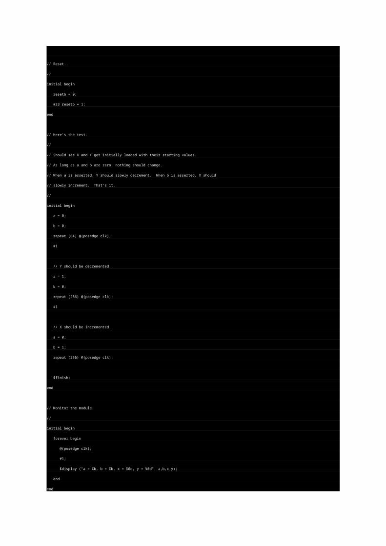
resetb = 0;
#33 resetb = 1;
end
// Here's the test.
//
// Should see X and Y get initially loaded with their starting values.
// As long as a and b are zero, nothing should change.
// When a is asserted, Y should slowly decrement. When b is asserted, X should
// slowly increment. That's it.
//
initial begin
a = 0;
b = 0;
repeat (64) @(posedge clk);
#1
// Y should be decremented..
a = 1;
b = 0;
repeat (256) @(posedge clk);
#1
// X should be incremented..
a = 0;
b = 1;
repeat (256) @(posedge clk);
$finish;
end
// Monitor the module.
//
initial begin
forever begin
@(posedge clk);
#1;
$display ("a = %b, b = %b, x = %0d, y = %0d", a,b,x,y);
end
end
endmodule
module shifter(in,clock,reset,out);
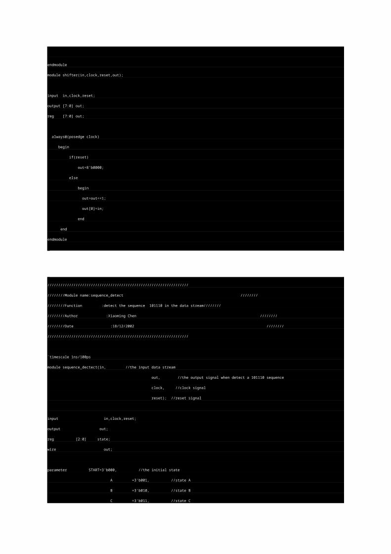
input in,clock,reset;
output [7:0] out;
reg [7:0] out;
always@(posedge clock)
begin
if(reset)
out=8'b0000;
else
begin
out=out<<1;
out[0]=in;
end
end
endmodule
/////////////////////////////////////////////////////////////////
////////Module name:sequence_detect ////////
////////Function :detect the sequence 101110 in the data stream////////
////////Author :Xiaoming Chen ////////
////////Date :18/12/2002 ////////
/////////////////////////////////////////////////////////////////
`timescale 1ns/100ps
module sequence_dectect(in, //the input data stream
out, //the output signal when detect a 101110 sequence
clock, //clock signal
reset); //reset signal
input in,clock,reset;
output out;
reg [2:0] state;
wire out;
parameter START=3'b000, //the initial state
A =3'b001, //state A
B =3'b010, //state B
C =3'b011, //state C
D =3'b100, //state D
E =3'b101, //state E
F =3'b110; //state F
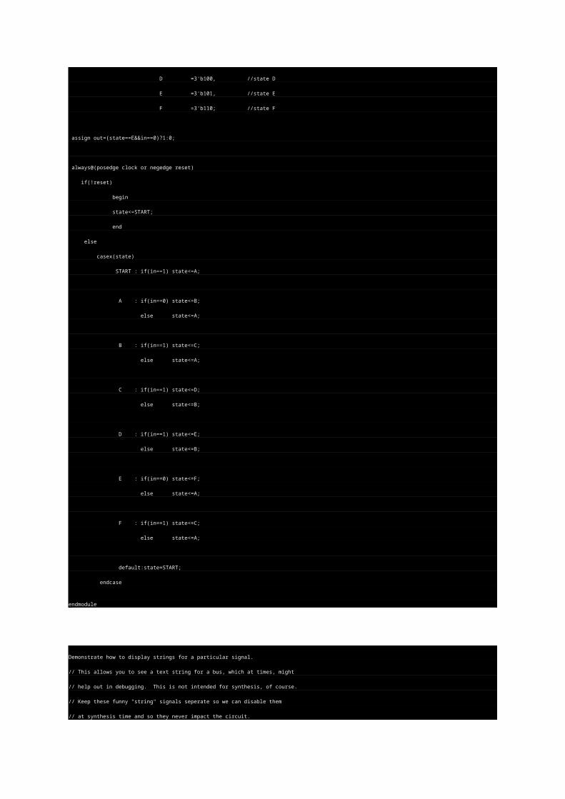
assign out=(state==E&&in==0)?1:0;
always@(posedge clock or negedge reset)
if(!reset)
begin
state<=START;
end
else
casex(state)
START : if(in==1) state<=A;
A : if(in==0) state<=B;
else state<=A;
B : if(in==1) state<=C;
else state<=A;
C : if(in==1) state<=D;
else state<=B;
D : if(in==1) state<=E;
else state<=B;
E : if(in==0) state<=F;
else state<=A;
F : if(in==1) state<=C;
else state<=A;
default:state=START;
endcase
endmodule
Demonstrate how to display strings for a particular signal.
// This allows you to see a text string for a bus, which at times, might
// help out in debugging. This is not intended for synthesis, of course.
// Keep these funny "string" signals seperate so we can disable them
// at synthesis time and so they never impact the circuit.
//
//
module test;
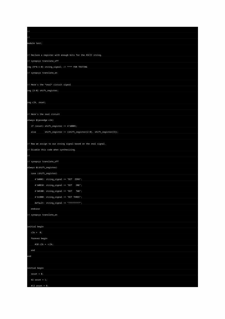
// Declare a register with enough bits for the ASCII string.
// synopsys translate_off
reg [9*8-1:0] string_signal; // **** FOR TESTING
// synopsys translate_on
// Here's the *real* circuit signal
reg [3:0] shift_register;
reg clk, reset;
// Here's the real circuit
always @(posedge clk)
if (reset) shift_register <= 4'b0001;
else shift_register <= {shift_register[2:0], shift_register[3]};
// Now we assign to our string signal based on the real signal.
// Disable this code when synthesizing.
//
// synopsys translate_off
always @(shift_register)
case (shift_register)
4'b0001: string_signal <= "BIT ZERO";
4'b0010: string_signal <= "BIT ONE";
4'b0100: string_signal <= "BIT TWO";
4'b1000: string_signal <= "BIT THREE";
default: string_signal <= "?????????";
endcase
// synopsys translate_on
initial begin
clk = 0;
forever begin
#10 clk = ~clk;
end
end
initial begin
reset = 0;
#2 reset = 1;
#13 reset = 0;
#200;
$finish;
end
// Generate VCD file for viewing.
//
// Once we are in the Waveform Viewer, just set the format of 'string_signal'
// to ASCII!
//
initial begin
$dumpfile ("test_string_signal.vcd");
$dumpvars (0,test);
end
endmodule
//////////////////////////////////////////////////////////////
////////Module name :test /////////////
////////Function :used to test the sequence_detect.v/////////////
////////Author :Xiaoming Chen /////////////
////////Date :18/12/2002 /////////////
//////////////////////////////////////////////////////////////
`include "sequence_dectect.v"
`timescale 1ns/100ps
module test;
reg clk,rst;
reg [63:0] data;
wire out_signal,current_bit;
assign current_bit=data[63];
initial
begin
clk<=0;
rst<=1;
#2 rst<=0;
#30 rst<=1;
data=64'b1101_1101_1101_0111_0111_0101_1100_0101_1101_1011_0001_0000_1011_1010_1100_0101;
end
always #10 clk=~clk;
always@(posedge clk)
data<={data[62:0],data[63]};
sequence_dectect m(current_bit,out_signal,clk,rst);
endmodule ...
Some Examples of Verilog testbench techniques.
1.0 Introduction
2.0 Generating Periodic Signals
3.0 Generating and Receiving Serial Characters
4.0 Memories
5.0 Bus Models
1.0 Introduction
A testbench is a verilog program that wraps around an actual design.
The testbench is typically not part of the design and does not result
in actual circuitry or gates. Verilog code for testbenches may be
much more "free style" than Verilog code that must be
synthesized - anything goes. Here are some tidbits from various
projects I've worked on. The code is not completely general nor
perfect, but hopefully may provide ideas for designers just starting
out with testbench design. Oh, and the names have been changed
to protect the innocent. I hope I haven't introduced error in
doctoring up these examples. Again, none of the following code
is intended to be synthesizable!
2.0 Generating Periodic Signals.
Say you have a period signal. Try tossing in a little random fluctuation
on where the edges occur - you may catch a an unexpected bug!
But, be careful about using random because if you move on to
manufacturing test, then your testbench may not be deterministic.
Often, for the sake of the tester, you must enforce transitions to
occur in specific periods. In this case, you may need to add
statements that delay changes to fall in these periods. Anyway,
let's drive the foo1in signal. We'll add in some random, count
the transitions and print out a message.
initial begin
#1 foo1in = 0;
forever begin
#(`PERIOD/2 + ($random % 10)*(` PERIOD/20)) foo1in = 1;
foo1_input_count = foo1_input_count + 1;
$display ("#Foo1 rising edges = %d", foo1_input_count);
#(` PERIOD/2 + ($random % 10)*(` PERIOD/20)) foo1in = 0;
end
end
Here's another code snippet - a task that generates a period message..
task generate_syncs;
event send_sync;
begin
syncdata = SYNC_START;
syncstb = 0;
fork
// Generate periodic event for sending the sync
forever #(1000000000.0 * RATE) ->send_sync; // convert RATE to nanoseconds
// Wait on send_sync event, and then send SYNC synchronized with clk
forever begin
@(send_sync);
syncdata = syncdata + CMTS_FREQ * CMTS_RATE;
$display ("... SYNC = %h at time %0t, Local Time = %h", syncdata, $time, local_time);
@(posedge clk) #1;
syncstb = 1;
@(posedge clk) #1;
syncstb = 0;
end
join
end
endtask
3.0 Generating and Receiving Serial Characters
Say your design inputs or outputs serial characters. Here is some
code for both. First, some defines:
/* Serial Parameters used for send_serial task and its callers. */
`define PARITY_OFF 1'b0
`define PARITY_ON 1'b1
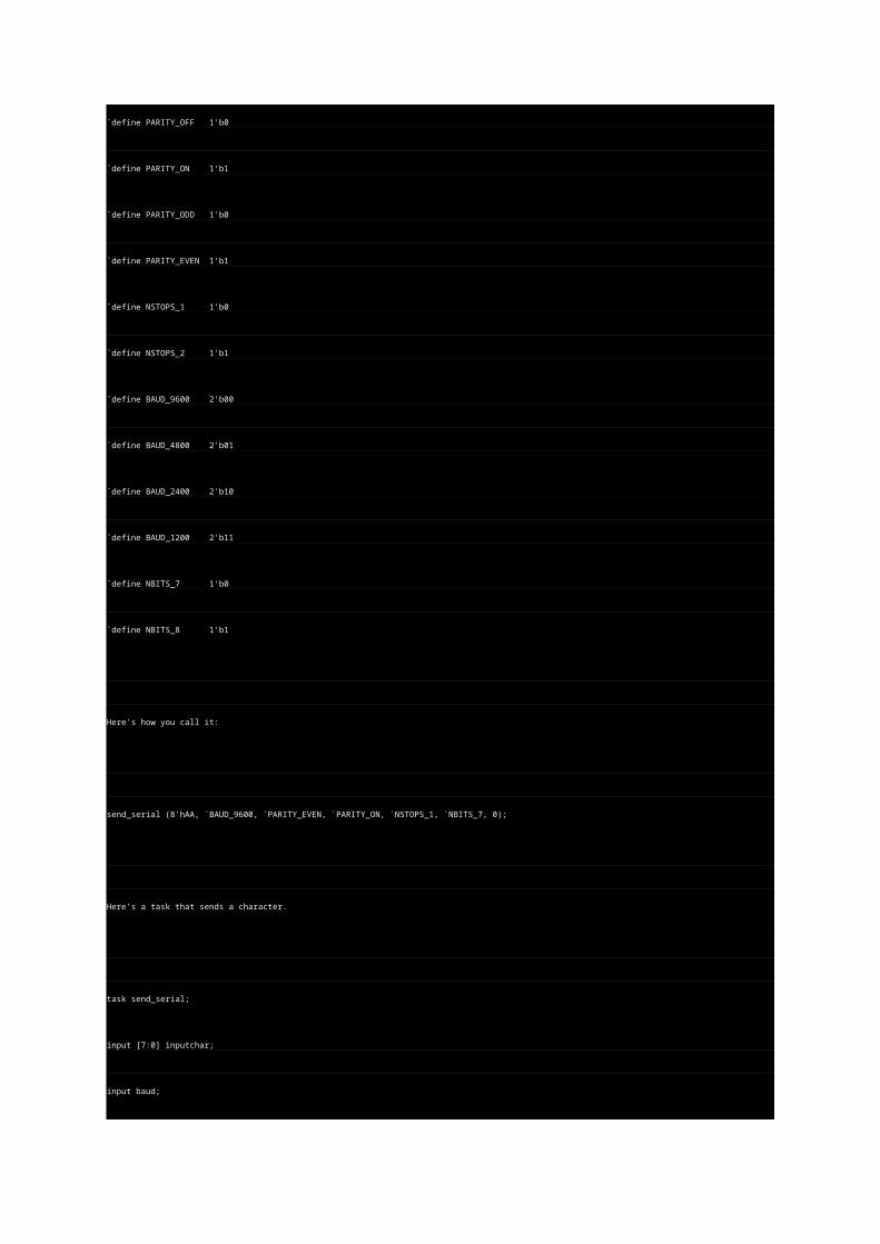
`define PARITY_ODD 1'b0
`define PARITY_EVEN 1'b1
`define NSTOPS_1 1'b0
`define NSTOPS_2 1'b1
`define BAUD_9600 2'b00
`define BAUD_4800 2'b01
`define BAUD_2400 2'b10
`define BAUD_1200 2'b11
`define NBITS_7 1'b0
`define NBITS_8 1'b1
Here's how you call it:
send_serial (8'hAA, `BAUD_9600, `PARITY_EVEN, `PARITY_ON, `NSTOPS_1, `NBITS_7, 0);
Here's a task that sends a character.
task send_serial;
input [7:0] inputchar;
input baud;
input paritytype;
input parityenable;
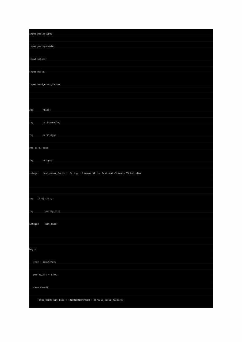
input nstops;
input nbits;
input baud_error_factor;
reg nbits;
reg parityenable;
reg paritytype;
reg [1:0] baud;
reg nstops;
integer baud_error_factor; // e.g. +5 means 5% too fast and -5 means 5% too slow
reg [7:0] char;
reg parity_bit;
integer bit_time;
begin
char = inputchar;
parity_bit = 1'b0;
case (baud)
`BAUD_9600: bit_time = 1000000000/(9600 + 96*baud_error_factor);
`BAUD_4800: bit_time = 1000000000/(4800 + 48*baud_error_factor);
`BAUD_2400: bit_time = 1000000000/(2400 + 24*baud_error_factor);
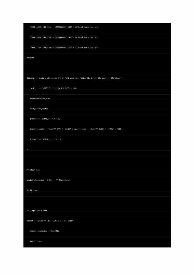
`BAUD_1200: bit_time = 1000000000/(1200 + 12*baud_error_factor);
endcase
$display ("Sending character %h, at %0d baud (err=%0d), %0d bits, %0s parity, %0d stops",
(nbits == `NBITS_7) ? (char & 8'h7f) : char,
1000000000/bit_time,
baud_error_factor,
(nbits == `NBITS_7) ? 7 : 8,
(parityenable == `PARITY_OFF) ? "NONE" : (paritytype == `PARITY_EVEN) ? "EVEN" : "ODD",
(nstops == `NSTOPS_1) ? 1 : 2
);
// Start bit
serial_character = 1'b0; // Start bit.
#(bit_time);
// Output data bits
repeat ( (nbits == `NBITS_7) ? 7 : 8) begin
serial_character = char[0];
#(bit_time);
char = {1'b0, char[7:1]};
end
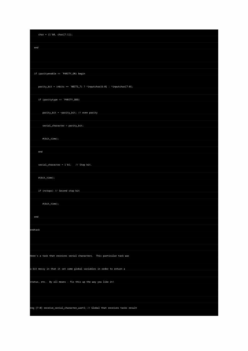
if (parityenable == `PARITY_ON) begin
parity_bit = (nbits == `NBITS_7) ? ^inputchar[6:0] : ^inputchar[7:0];
if (paritytype == `PARITY_ODD)
parity_bit = ~parity_bit; // even parity
serial_character = parity_bit;
#(bit_time);
end
serial_character = 1'b1; // Stop bit.
#(bit_time);
if (nstops) // Second stop bit
#(bit_time);
end
endtask
Here's a task that receives serial characters. This particular task was
a bit messy in that it set some global variables in order to return a
status, etc. By all means - fix this up the way you like it!
reg [7:0] receive_serial_character_uart1; // Global that receives tasks result
// **** SERIAL CHARACTER LISTENER Task for UART1
//
//
task receive_serial_uart1;
input baud;
input paritytype;
input parityenable;
input nstops;
input nbits;
reg nbits;
reg parityenable;
reg paritytype;
reg [1:0] baud;
reg nstops;
integer bit_time;
reg expected_parity;
begin
receive_serial_result_uart1 = 0;
receive_serial_character_uart1 = 0;
case (baud)
`BAUD_9600: bit_time = 1000000000/(9600);
`BAUD_4800: bit_time = 1000000000/(4800);
`BAUD_2400: bit_time = 1000000000/(2400);
`BAUD_1200: bit_time = 1000000000/(1200);
endcase
receive_serial_result_uart1 = `RECEIVE_RESULT_OK; // Assume OK until bad things happen.
@(negedge uart1out); // wait for start bit edge
#(bit_time/2); // wait till center of start bit
if (uart1out != 0) // make sure its really a start bit
receive_serial_result_uart1 = receive_serial_result_uart1 | `RECEIVE_RESULT_FALSESTART;
else begin
repeat ( (nbits == `NBITS_7) ? 7 : 8) begin // get all the data bits (7 or 8)
#(bit_time); // wait till center
// sample a data bit
receive_serial_character_uart1 = {uart1out, receive_serial_character_uart1[7:1]};
end
// If we are only expecting 7 bits, go ahead and right-justify what we have
if (nbits == `NBITS_7)
receive_serial_character_uart1 = {1'b0, receive_serial_character_uart1[7:1]};
#(bit_time);
// now, we have either a parity bit, or a stop bit
if (parityenable == `PARITY_ON) begin
if (paritytype == `PARITY_EVEN)
expected_parity = (nbits == `NBITS_7) ? (^receive_serial_character_uart1[6:0]) :
(^receive_serial_character_uart1[7:0]);
else
expected_parity = (nbits == `NBITS_7) ? (~(^receive_serial_character_uart1[6:0])) :
(~(^receive_serial_character_uart1[7:0]));
if (expected_parity != uart1out)
receive_serial_result_uart1 = receive_serial_result_uart1 | `RECEIVE_RESULT_BADPARITY;
// wait for either 1 or 2 stop bits
end
else begin
// this is a stop bit.
if (uart1out != 1)
receive_serial_result_uart1 = receive_serial_result_uart1 | `RECEIVE_RESULT_BADSTOP;
else
// that was cool. if 2 stops, then do this again
if (nstops) begin
#(bit_time);
if (uart1out != 1)
receive_serial_result_uart1 = receive_serial_result_uart1 | `RECEIVE_RESULT_BADSTOP;
end
#(bit_time/2);
end
end
end
endtask
4.0 Memories
Memories, whether they are RAMs, ROMs or special memories like FIFOs
are easily modeled in Verilog. Note that you can define your own special
testbench locations for debugging! Say, you have a processor core hooked
up to these memories. Define some special locations that when read or
written to, display diagnostic messages. Or, you can specify that a write to
a particular location will halt the simulation or signify PASS or FAIL.
Memories are an easy way for the embedded Verilog core processor to
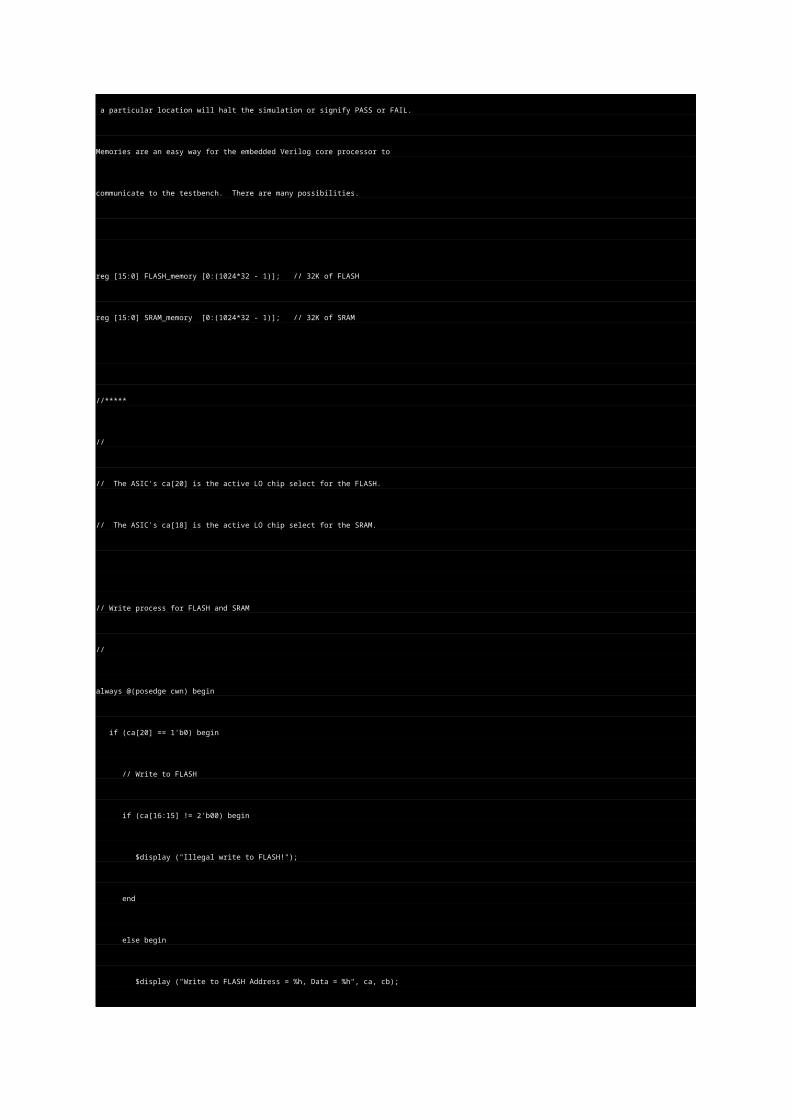
communicate to the testbench. There are many possibilities.
reg [15:0] FLASH_memory [0:(1024*32 - 1)]; // 32K of FLASH
reg [15:0] SRAM_memory [0:(1024*32 - 1)]; // 32K of SRAM
//*****
//
// The ASIC's ca[20] is the active LO chip select for the FLASH.
// The ASIC's ca[18] is the active LO chip select for the SRAM.
// Write process for FLASH and SRAM
//
always @(posedge cwn) begin
if (ca[20] == 1'b0) begin
// Write to FLASH
if (ca[16:15] != 2'b00) begin
$display ("Illegal write to FLASH!");
end
else begin
$display ("Write to FLASH Address = %h, Data = %h", ca, cb);
// Our FLASH is only declared up to 32KW, so use ca[14:0]
FLASH_memory[ca[14:0]] = cb;
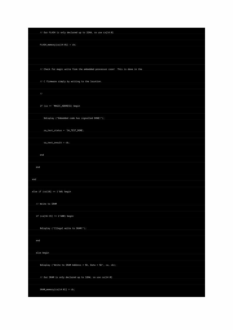
// Check for magic write from the embedded processor core! This is done in the
// C firmware simply by writing to the location.
//
if (ca == `MAGIC_ADDRESS) begin
$display ("Embedded code has signalled DONE!");
sa_test_status = `SA_TEST_DONE;
sa_test_result = cb;
end
end
end
else if (ca[18] == 1'b0) begin
// Write to SRAM
if (ca[16:15] != 2'b00) begin
$display ("Illegal write to SRAM!");
end
else begin
$display ("Write to SRAM Address = %h, Data = %h", ca, cb);
// Our SRAM is only declared up to 32KW, so use ca[14:0]
SRAM_memory[ca[14:0]] = cb;
end
end
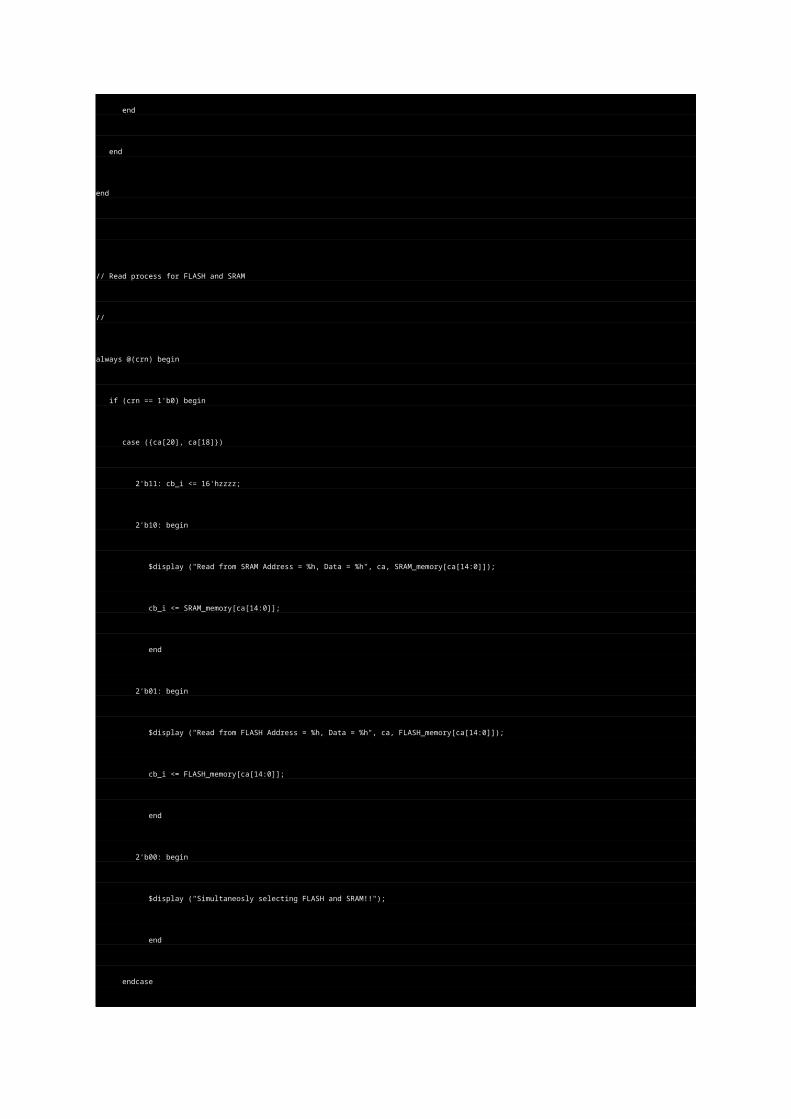
end
// Read process for FLASH and SRAM
//
always @(crn) begin
if (crn == 1'b0) begin
case ({ca[20], ca[18]})
2'b11: cb_i <= 16'hzzzz;
2'b10: begin
$display ("Read from SRAM Address = %h, Data = %h", ca, SRAM_memory[ca[14:0]]);
cb_i <= SRAM_memory[ca[14:0]];
end
2'b01: begin
$display ("Read from FLASH Address = %h, Data = %h", ca, FLASH_memory[ca[14:0]]);
cb_i <= FLASH_memory[ca[14:0]];
end
2'b00: begin
$display ("Simultaneosly selecting FLASH and SRAM!!");
end
endcase
end
else begin
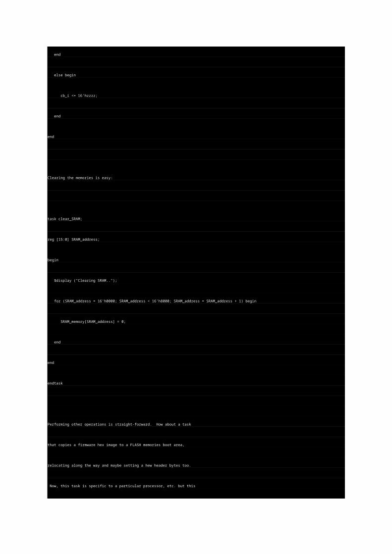
cb_i <= 16'hzzzz;
end
end
Clearing the memories is easy:
task clear_SRAM;
reg [15:0] SRAM_address;
begin
$display ("Clearing SRAM..");
for (SRAM_address = 16'h0000; SRAM_address < 16'h8000; SRAM_address = SRAM_address + 1) begin
SRAM_memory[SRAM_address] = 0;
end
end
endtask
Performing other operations is straight-forward. How about a task
that copies a firmware hex image to a FLASH memories boot area,
relocating along the way and maybe setting a hew header bytes too.
Now, this task is specific to a particular processor, etc. but this
shows what is fairly easily done in Verilog:
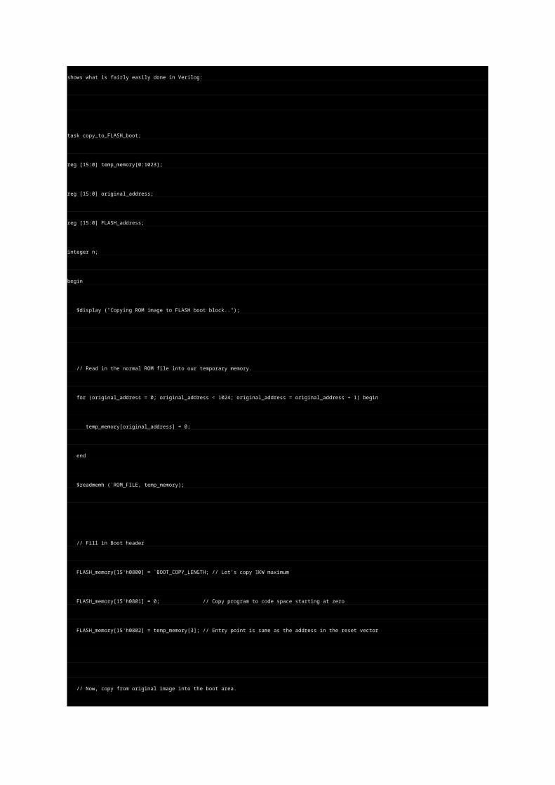
task copy_to_FLASH_boot;
reg [15:0] temp_memory[0:1023];
reg [15:0] original_address;
reg [15:0] FLASH_address;
integer n;
begin
$display ("Copying ROM image to FLASH boot block..");
// Read in the normal ROM file into our temporary memory.
for (original_address = 0; original_address < 1024; original_address = original_address + 1) begin
temp_memory[original_address] = 0;
end
$readmemh (`ROM_FILE, temp_memory);
// Fill in Boot header
FLASH_memory[15'h0800] = `BOOT_COPY_LENGTH; // Let's copy 1KW maximum
FLASH_memory[15'h0801] = 0; // Copy program to code space starting at zero
FLASH_memory[15'h0802] = temp_memory[3]; // Entry point is same as the address in the reset vector
// Now, copy from original image into the boot area.
n = 0;
FLASH_address = 15'h0803;
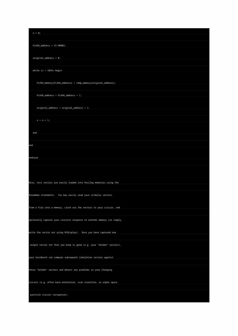
original_address = 0;
while (n < 1024) begin
FLASH_memory[FLASH_address] = temp_memory[original_address];
FLASH_address = FLASH_address + 1;
original_address = original_address + 1;
n = n + 1;
end
end
endtask
Also, test vectors are easily loaded into Verilog memories using the
$readmem statements. You may easily read your stimulus vectors
from a file into a memory, clock out the vectors to your circuit, and
optionally capture your circuits response to another memory (or simply
write the vector out using $fdisplay). Once you have captured one
output vector set that you know is good (e.g. your "Golden" vectors),
your testbench can compare subsequent simulation vectors against
these "Golden" vectors and detect any problems in your changing
circuit (e.g. after back-annotation, scan insertion, or alpha space
particle circuit corruption).
5.0 Bus Models
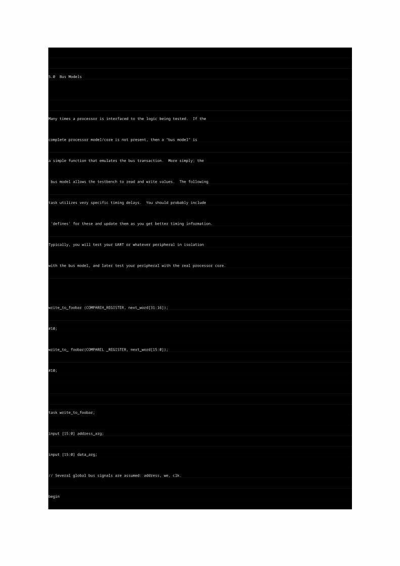
Many times a processor is interfaced to the logic being tested. If the
complete processor model/core is not present, then a "bus model" is
a simple function that emulates the bus transaction. More simply; the
bus model allows the testbench to read and write values. The following
task utilizes very specific timing delays. You should probably include
'defines' for these and update them as you get better timing information.
Typically, you will test your UART or whatever peripheral in isolation
with the bus model, and later test your peripheral with the real processor core.
write_to_foobar (COMPAREH_REGISTER, next_word[31:16]);
#10;
write_to_ foobar(COMPAREL _REGISTER, next_word[15:0]);
#10;
task write_to_foobar;
input [15:0] address_arg;
input [15:0] data_arg;
// Several global bus signals are assumed: address, we, clk.
begin
/* Wait until next rising clock edge */
@(posedge clk);
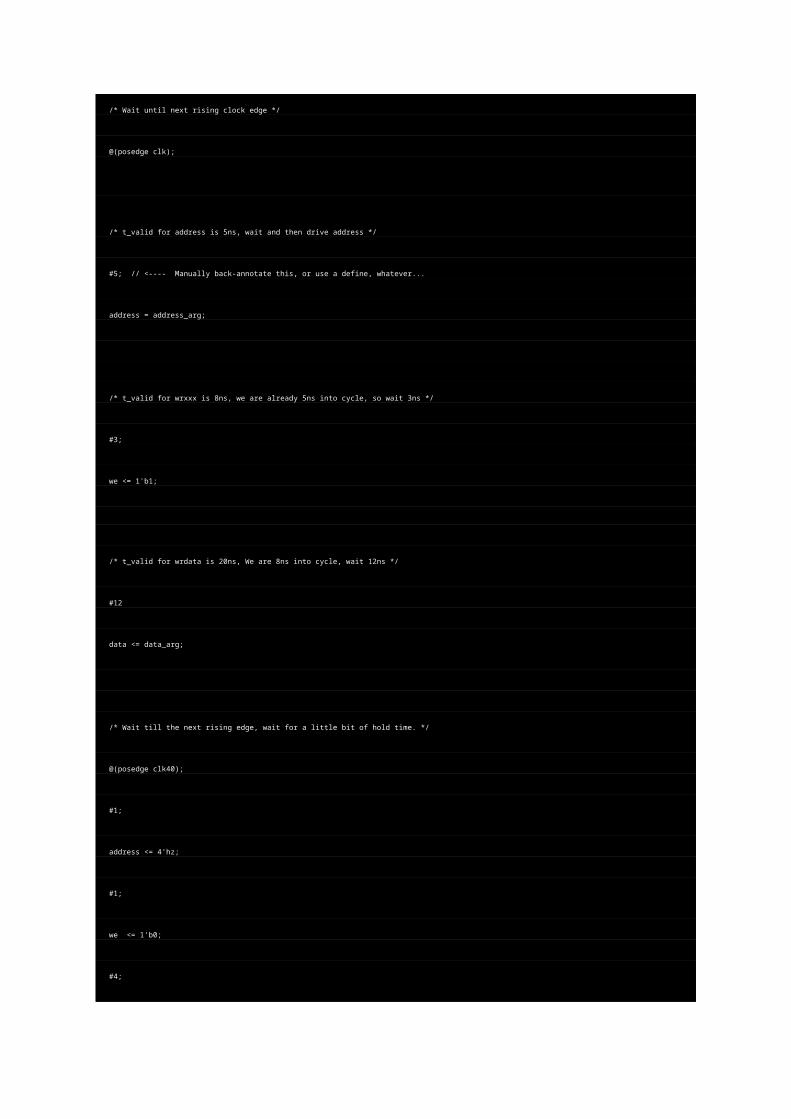
/* t_valid for address is 5ns, wait and then drive address */
#5; // <---- Manually back-annotate this, or use a define, whatever...
address = address_arg;
/* t_valid for wrxxx is 8ns, we are already 5ns into cycle, so wait 3ns */
#3;
we <= 1'b1;
/* t_valid for wrdata is 20ns, We are 8ns into cycle, wait 12ns */
#12
data <= data_arg;
/* Wait till the next rising edge, wait for a little bit of hold time. */
@(posedge clk40);
#1;
address <= 4'hz;
#1;
we <= 1'b0;
#4;
data <= 16'hzzzz;
//$display ("Writing data %h to address: %h", data, address);
end
endtask
Here's a task that reads from the memory-mapped peripheral.
task read_from_foobar;
input [3:0] address_arg;
// Let's just write to a global with the resulting data retrieved (! bad practice, I know....)
// Gobal variable is 'last_data_read'.
begin
/* Wait until next rising edge to do anything.. */
@(posedge clk)
/* t_valid for rwadrs is 5ns, wait and then drive address */
#5;
address = address_arg;
/* t_valid for rbxxx is 8ns, we are already 5ns into cycle, so wait 3ns */
#3;
rw <= 1'b1;
/* Wait till the next rising edge, wait for a little bit of hold time. */
@(posedge clk);
last_data_read = data; // <-- keep in the global, caller can use if they wish.
$display ("Reading data %h from address: %h", data, address);
/* Wrap it up. Deassert rw. Let's float the address bus. */
rw <= 1'b0;
#1;
address <= 16'hzzzz;
end
endtask
`include "cla_8bits.v"
module test_cla_8bits;
reg [7:0] m,n;
reg cin;
wire [7:0] sum;
wire cout;
cla_8bits tt (m,n,cin,cout,sum);
initial
begin
#40
cin= 1;
m = 8'b10101100;
n = 8'b11010101;
#40
cin= 1;
m = 8'b10001111;
n= 8'b10001111;
#40
cin= 0;
m = 8'b01010101;
n = 8'b10101010;
end
always@(m or n or cin)
begin
#20
$display("a=%b b=%b cin=%b cout=%b sum=%b",m,n,cin,cout,sum);
end
endmodule
This circuit generates WE pulses. For example, if you have a chip that
// needs to access an asynchronous SRAM in a single cycle and you wanted
// generate the WE pulse synchronous with your system clock.
//
// Every clk cycle, generate an active
// low WE pulse. The delay from the clk rising edge to the falling edge of
// we is based on abits setting, which affects delay taps, etc. Likewise,
// bbits controls the following rising edge of we. The module contains
// two flip flops that generate two opposite poraity toggling levels.
// A delay chain is attached to each of these outputs. The abits and bbits
// get the desired tap, and the final two delayed signals are XORed together
// to get the final we. None of this is very tuned, you would look at your
// cycle time and pick a delay chain that makes sense for that. But, this
// shows the effect.
//
// The we pulse always occurs. You will probably want to combine this with
// you write_enable signal. This sort of circuit is, of course, highly dependent
// on post-layout timing, etc. but that's why its programable. You probably
// want more taps, too..
//
//
module wpulse (
reset,
clk,
abits,
bbits,
we
);
input clk;
input reset;
input [3:0] abits; // bits to select which delay tap to use for first edge
input [3:0] bbits; // bits to select which delay tap to use for pulse width
output we;
reg p1, p2;
wire adel1out;
wire adel2out;
wire adel3out;
wire adel4out;
wire bdel1out;
wire bdel2out;
wire bdel3out;
wire bdel4out;
wire adelout;
wire bdelout;
// 2 flip-flops that are opposite polarity. Each flop toggles
// every cycles.
//
always @(posedge clk)
p1 <= (reset) | (~reset & ~p1); // reset to 1
always @(posedge clk)
p2 <= (~reset & ~p2); // reset to 0
// Delay chain off of the p1 flop.
delay4 adel1 (.a(p1), .z(adel1out));
delay4 adel2 (.a(adel1out), .z(adel2out));
delay4 adel3 (.a(adel2out), .z(adel3out));
delay4 adel4 (.a(adel3out), .z(adel4out));
// Delay chain off of the p2 flop.
delay4 bdel1 (.a(p2), .z(bdel1out));
delay4 bdel2 (.a(bdel1out), .z(bdel2out));
delay4 bdel3 (.a(bdel2out), .z(bdel3out));
delay4 bdel4 (.a(bdel3out), .z(bdel4out));
// Select the tap of the p1 and p2 delay chains we want based on abits
assign adelout = abits[3] & adel1out |
abits[2] & adel2out |
abits[1] & adel3out |
abits[0] & adel4out;
assign bdelout = bbits[3] & bdel1out |
bbits[2] & bdel2out |
bbits[1] & bdel3out |
bbits[0] & bdel4out;
// Final we pulse is just the XOR of the two chains.
assign we = adelout ^ bdelout;
endmodule
// This is our delay cell. Pick whatever cell makes sense from your library.
module delay4 (a, z);
input a;
output z;
reg z;
always @(a)
z = #4 a;
endmodule
// synopsys translate_off
module testwpulse;
reg clk;
reg reset;
reg [3:0] abits; // bits to select which delay tap to use for first edge
reg [3:0] bbits; // bits to select which delay tap to use for pulse width
wire we;
wpulse wpulse_inst (
.reset (reset),
.clk (clk),
.abits (abits),
.bbits (bbits),
.we (we)
);
initial begin
abits = 4'b1000; // Shortest pulse, earliest in cycle.
bbits = 4'b0100;
#200;
abits = 4'b0010; // Shortest pulse, latest in the cycle.
bbits = 4'b0001;
#200;
abits = 4'b0100; // Shortest pulse, middle of the cycle.
bbits = 4'b0010;
#200;
abits = 4'b1000; // Longest cycle
bbits = 4'b0001;
#200;
abits = 4'b1000; // Early in cycle, but not quite the longest.
bbits = 4'b0010;
#200;
$finish;
end
// Reset
initial begin
reset = 0;
#5 reset = 1;
#100 reset = 0;
end
// Generate the 50MHz clock
initial begin
clk = 0;
forever begin
#10 clk = 1;
#10 clk = 0;
end
end
`define WAVES
`ifdef WAVES
initial begin
$dumpfile ("wpulse.vcd");
$dumpvars (0,testwpulse);
end
`endifendmodule
nco code list
Hey everyone, well I have a little problem related to the same topic, the nco,
I have the VHDL code for all the components, but I don't know how to make the main code, relating all this components, can anyone help me, please?
adder
library IEEE;use IEEE.STD_LOGIC_1164.ALL;use IEEE.STD_LOGIC_ARITH.ALL;use IEEE.STD_LOGIC_UNSIGNED.ALL;
entity additionneur isport(accum,offset,Q:in std_logic_vector (17 downto 0);C0,S :out std_logic_vector (17 downto 0));end additionneur;
architecture Behavioral of additionneur iscomponent demi_additionneurport(accum,offset:in std_logic_vector (17 downto 0);R,S:out std_logic_vector (17 downto 0));end component;signal S1,S2,S3:std_logic_vector(17 downto 0);Begininstance1:demi_additionneur port map(accum,offset,S1,S2);instance2:demi_additionneur port map(S2,Q,S3,S);
C0<= S1 or S3;
end Behavioral;
half-adder
library IEEE;use IEEE.STD_LOGIC_1164.ALL;use IEEE.STD_LOGIC_ARITH.ALL;use IEEE.STD_LOGIC_UNSIGNED.ALL;
entity demi_additionneur isport(accum,offset:in std_logic_vector (17 downto 0);R,S:out std_logic_vector (17 downto 0));end demi_additionneur;architecture Behavioral of demi_additionneur isbeginS<=accum xor offset;R<=accum and offset;end Behavioral;
latch
library IEEE;use IEEE.STD_LOGIC_1164.ALL;use IEEE.STD_LOGIC_ARITH.ALL;use IEEE.STD_LOGIC_UNSIGNED.ALL;
entity bascule isport( D:in std_logic_vector (17 downto 0);clk:in std_logic;reset: in std_logic;Q:out std_logic_vector (17 downto 0)
);end bascule;
architecture Behavioral of bascule is
beginprocess (clk,reset)
beginif (reset='1') then Q<="000000000000000000";elsif (clk'event and clk='1') then Q<=D ;end if;
end process;end Behavioral;
cosineROMlibrary IEEE;use IEEE.STD_LOGIC_1164.ALL;use IEEE.STD_LOGIC_ARITH.ALL;use IEEE.STD_LOGIC_UNSIGNED.ALL;
entity cosrom isport (
Entree: in std_logic_vector(17 downto 0);output: out std_logic_vector(7 downto 0));end cosrom;
architecture Behavioral of cosrom istype cosROM_Array is array (0 to 256) of std_logic_vector(6 downto 0);constant Table : cosROM_Array := ( 0 => "1000011",1 => "1111111",2 => "1111001",3 => "1111111",4 => "1111100",5 => "1111111",6 => "1111111",7 => "1111111",8 => "1111111",9 => "1111111",10 => "1111111",11 => "1111111",12 => "1111111",13 => "1111111",14 => "1111111",15 => "1111111",16 => "1111111",17 => "1111111",18 => "1111111",19 => "1111111",20 => "1111111",21 => "1111111",22 => "1111111",23 => "1111111",24 => "1111111",25 => "1111111",26 => "1111110",27 => "1111110",28 => "1111110",29 => "1111110",30 => "1111110",31 => "1111110",32 => "1111110",33 => "1111110",34 => "1111101",35 => "1111101",36 => "1111101",37 => "1111101",38 => "1111101",39 => "1111100",40 => "1111100",41 => "1111100",42 => "1111100",43 => "1111100",44 => "1111011",45 => "1111011",46 => "1111011",47 => "1111011",48 => "1111010",49 => "1111010",50 => "1111010",51 => "1111010",52 => "1111010",53 => "1111010",54 => "1111001",55 => "1111001",56 => "1111001",57 => "1111001",58 => "1111001",59 => "1111000",60 => "1111000",61 => "1111000",62 => "1110111",63 => "1110111",64 => "1110111",65 => "1110111",66 => "1110110",67 => "1110110",68 => "1110110",69 => "1110101",70 => "1110101",71 => "1110101",72 => "1110100",73 => "1110100",74 => "1110100",75 => "1110010",76 => "1110010",77 => "1110010",78 => "1110001",79 => "1110001",80 => "1110001",81 => "1110000",82 => "1110000",83 => "1101110",84 => "1101110",85 => "1101101",86 => "1101101",87 => "1101101",88 => "1101100",89 => "1101100",90 => "1101011",91 => "1101011",92 => "1101010",93 => "1101010",94 => "1101010",95 => "1101001",96 => "1101001",97 => "1101000",98 => "1101000",99 => "1100111",100 => "1100111",101 => "1100110",102 => "1100110",103 => "1100110", 104 => "1100101",105 => "1100101", 106 => "1100100",
107 => "1100100",108 => "1100011",109 => "1100011",110 => "1100010",111 => "1100010",112 => "1100001",113 => "1100001",114 => "1100000",115 => "1100000",116 => "1011111",117 => "1011111",118 => "1011110",119 => "1011110",120 => "1011101",121 => "1011101",122 => "1011100",123 => "1011100",124 => "1011011",125 => "1011011",126 => "1011010",127 => "1011001",128 => "1011000",129 => "1011000",130 => "1010111",131 => "1010111",132 => "1010100",133 => "1010100",134 => "1010011",135 => "1010010",136 => "1010010",137 => "1010001",138 => "1010001",139 => "1010000",140 => "1001111",141 => "1001111",142 => "1001110",143 => "1001110",144 => "1001101",145 => "1001100",146 => "1001100",147 => "1001011",148 => "1001010",149 => "1001010",150 => "1001001",151 => "1001000",152 => "1001000",153 => "1000111",154 => "1000111",155 => "1111111",156 => "1000110",157 => "1000101",158 => "1000101",159 => "1000100",160 => "1000011",161 => "1000011",162 => "1000010",163 => "1111101",164 => "1000001",165 => "1000001",166 => "1000000",167 => "0111111",168 => "0111110",169 => "0111110",170 => "0111101",171 => "0111100",172 => "0111100",173 => "0111011",174 => "0111010",175 => "0111010",176 => "0111001",177 => "0111000",178 => "0110111",179 => "0110110",180 => "0110101",181 => "0110101",182 => "0110100",183 => "0110011",184 => "0110011",185 => "0110010",186 => "0110001",187 => "0110000",188 => "0110000",189 => "0101111",190 => "0101110",191 => "0101101",192 => "0101101",193 => "0101100",194 => "0101011",195 => "0101010",196 => "0101010",197 => "0101001",198 => "0101000",199 => "0100111",200 => "0100111",201 => "0100110",202 => "0100111",203 => "0100111",204 => "0100110",205 => "0100101",206 => "0100100",207 => "0100100",208 => "0100011",209 => "0100010",210 => "0100001",211 => "0100001",212 => "0100000",213 => "0100001",214 => "0100001",215 => "0100000",
216 => "0011111",217 => "0011110",218 => "0011110",219 => "0011101",220 => "0011100",221 => "0011011",222 => "0011011",223 => "0011010",224 => "0011001",225 => "0011000",226 => "0011000",227 => "0010111",228 => "0010110",229 => "0010101",230 => "0010100",231 => "0010100",232 => "0010011",233 => "0010010",234 => "0010001",235 => "0010001",236 => "0010000",237 => "0001111",238 => "0001110",239 => "0001101",240 => "0001101",241 => "0001100",242 => "0001011",243 => "0001010",244 => "0001010",245 => "0001001",246 => "0001000",247 => "0000111",248 => "0000110",249 => "0000110",250 => "0000101",251 => "0000100",252 => "0000011",253 => "0000010",254 => "0000010",255 => "0000001",256 => "1111111");beginprocess(Entree)beginif (Entree >= "000000000" and Entree <= "100000000") then output <= '0' & Table (conv_integer(Entree));elsif (Entree > "100000000" and Entree <= "1000000000") then output <= '1' & Table (512- conv_integer(Entree));elsif (Entree > "1000000000" and Entree <= "1100000000") then output <= '1' & Table ( conv_integer(Entree)- 512);elsif (Entree > "11000000000" and Entree <= "10000000000") then output <= '0' & Table ( 1024 - conv_integer(Entree));end if;end process;
end Behavioral;