Embed Size (px)
Citation preview
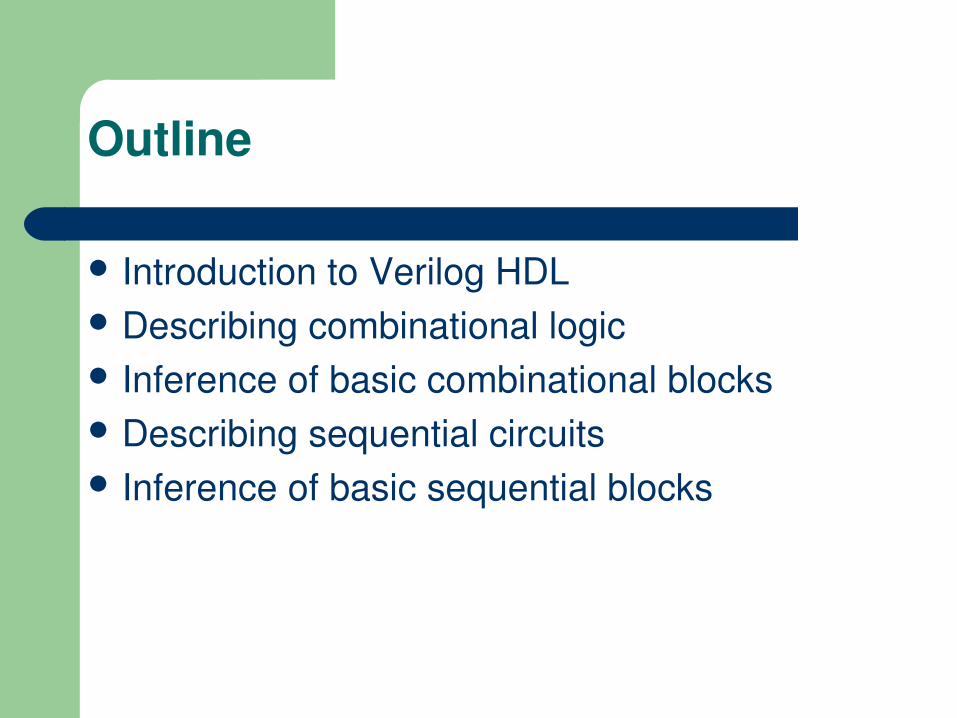
Introduction to Verilog HDL Describing combinational logic Inference of basic combinational blocks Describing sequential circuits Inference of basic sequential blocks
Outline
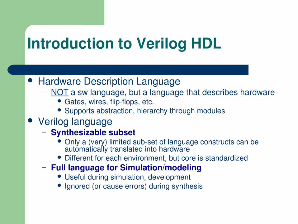
Hardware Description Language– NOT a sw language, but a language that describes hardware
Gates, wires, flipflops, etc. Supports abstraction, hierarchy through modules
Verilog language– Synthesizable subset
Only a (very) limited subset of language constructs can be automatically translated into hardware
Different for each environment, but core is standardized– Full language for Simulation/modeling
Useful during simulation, development Ignored (or cause errors) during synthesis
Introduction to Verilog HDL
Modules
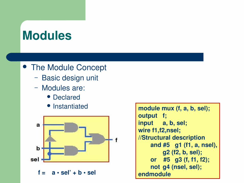
The Module Concept– Basic design unit– Modules are:
Declared Instantiated module mux (f, a, b, sel);
output f;input a, b, sel;wire f1,f2,nsel;//Structural description and #5 g1 (f1, a, nsel),
g2 (f2, b, sel);or #5 g3 (f, f1, f2);not g4 (nsel, sel);
endmodulef = a • sel’ + b • sel

Synthesis of combinational logic
Using procedural statements in Verilog– Logic is specified in “always” statements ( no “Initial”) – Each “always” statement turns into Boolean functions
module blah(output f,input a, b, c);reg f;always @ (a or b or c)
beginf = a | b | c;stuff...stuff...
endendmodule
You have to declare the combinational outputs like this, for synthesis. i.e., tool needs to think you are putting these computed outputs someplace.
Actually do logic in here. There are a bunch of subtle rules to ensure that synthesis won’t mess this up... We’ll see how…
You have to list all the block’s inputs here in the “sensitivity list”. (*) also works!
Synthesis of combinational logic(cont.)
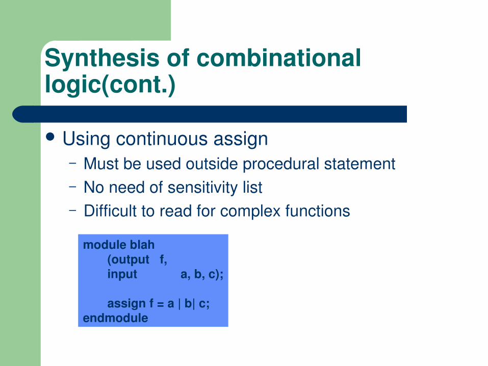
Using continuous assign– Must be used outside procedural statement– No need of sensitivity list– Difficult to read for complex functions
module blah(output f,input a, b, c);
assign f = a | b| c;endmodule
The Basic Rules
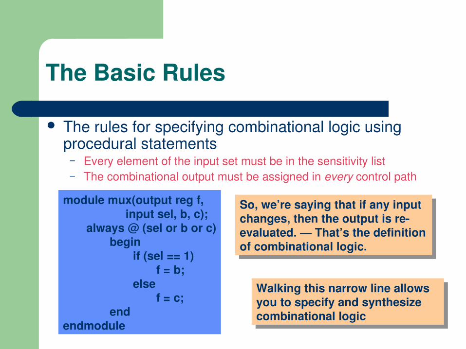
The rules for specifying combinational logic using procedural statements
– Every element of the input set must be in the sensitivity list– The combinational output must be assigned in every control path
Walking this narrow line allows you to specify and synthesize combinational logic
So, we’re saying that if any input changes, then the output is reevaluated. — That’s the definition of combinational logic.
module mux(output reg f, input sel, b, c);always @ (sel or b or c)
beginif (sel == 1)
f = b;else
f = c;end
endmodule
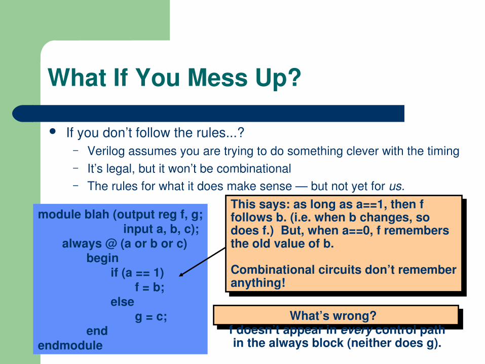
What If You Mess Up?
If you don’t follow the rules...? – Verilog assumes you are trying to do something clever with the timing– It’s legal, but it won’t be combinational– The rules for what it does make sense — but not yet for us.
module blah (output reg f, g; input a, b, c);always @ (a or b or c)
beginif (a == 1)
f = b;else
g = c;end
endmodule
What’s wrong?
This says: as long as a==1, then f follows b. (i.e. when b changes, so does f.) But, when a==0, f remembers the old value of b.
Combinational circuits don’t remember anything!
f doesn’t appear in every control path in the always block (neither does g).
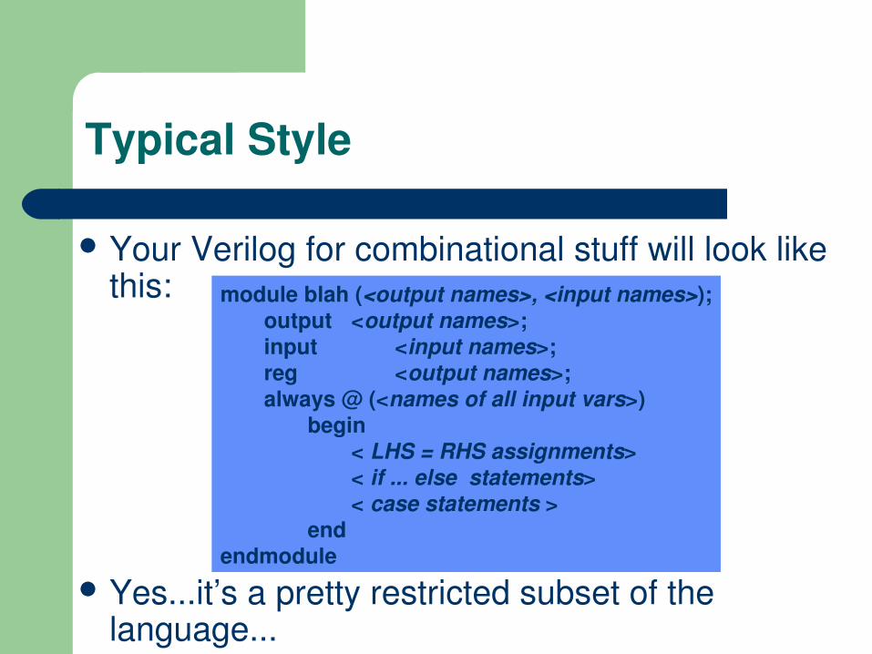
Typical Style
Your Verilog for combinational stuff will look like this:
Yes...it’s a pretty restricted subset of the language...
module blah (<output names>, <input names>);output <output names>;input <input names>;reg <output names>;always @ (<names of all input vars>)
begin< LHS = RHS assignments>< if ... else statements>< case statements >
endendmodule

Useful tricks…
Assigning in every control path– If the function is complex, you don’t know if you assigned to the
outputs in every control path.– So, set all outputs to some known value (zero here) and write the
code to set them to other values as needed.– Synthesis tools will figure it out, but try to write clearly.
always @(coke or cola) beginblah1 = 0;blah2 = 0;if (coke)
blah1 = 1;else if (cola > 2’b01)
blah2 = coke;else if ( ……
end
always @(coke or cola) beginif (coke)
blah1 = 1;else if (cola > 2’b01)
blah2 = coke;else if ( ……
end
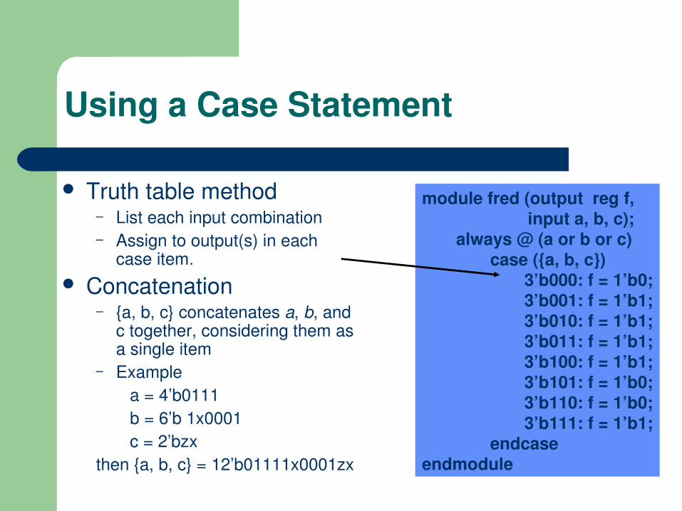
Using a Case Statement
Truth table method– List each input combination– Assign to output(s) in each
case item. Concatenation
– {a, b, c} concatenates a, b, and c together, considering them as a single item
– Example a = 4’b0111 b = 6’b 1x0001 c = 2’bzxthen {a, b, c} = 12’b01111x0001zx
module fred (output reg f, input a, b, c);always @ (a or b or c)
case ({a, b, c})3’b000: f = 1’b0;3’b001: f = 1’b1;3’b010: f = 1’b1;3’b011: f = 1’b1;3’b100: f = 1’b1;3’b101: f = 1’b0;3’b110: f = 1’b0;3’b111: f = 1’b1;
endcaseendmodule
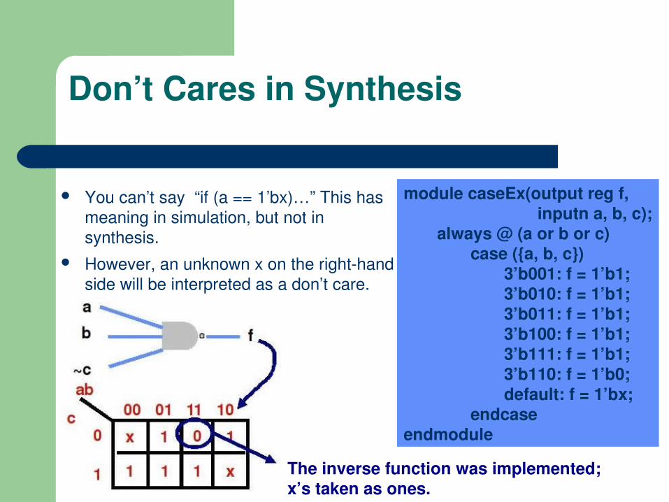
Don’t Cares in Synthesis
You can’t say “if (a == 1’bx)…” This has meaning in simulation, but not in synthesis.
However, an unknown x on the righthand side will be interpreted as a don’t care.
module caseEx(output reg f, inputn a, b, c);
always @ (a or b or c)case ({a, b, c})
3’b001: f = 1’b1;3’b010: f = 1’b1;3’b011: f = 1’b1;3’b100: f = 1’b1;3’b111: f = 1’b1;3’b110: f = 1’b0;default: f = 1’bx;
endcaseendmodule
The inverse function was implemented;x’s taken as ones.
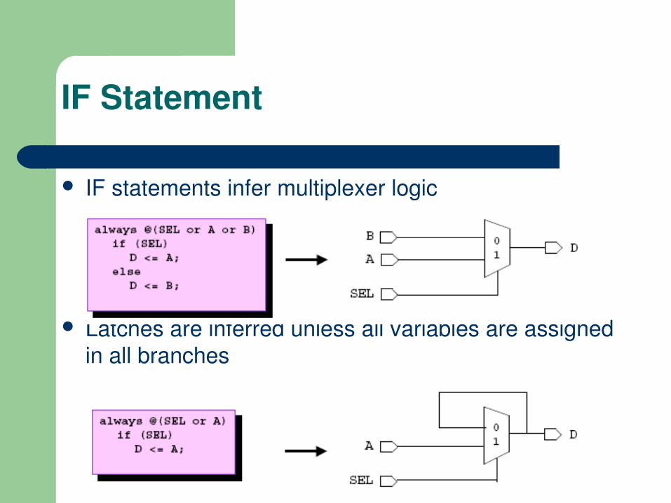
IF statements infer multiplexer logic
Latches are inferred unless all variables are assigned in all branches
IF Statement

IF Statements (cont.)
IFELSEIF statements infer priorityencoded multiplexers
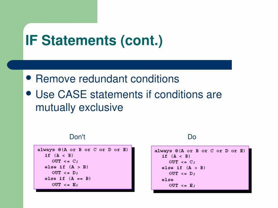
IF Statements (cont.)
Remove redundant conditions Use CASE statements if conditions are
mutually exclusive
Don't Do
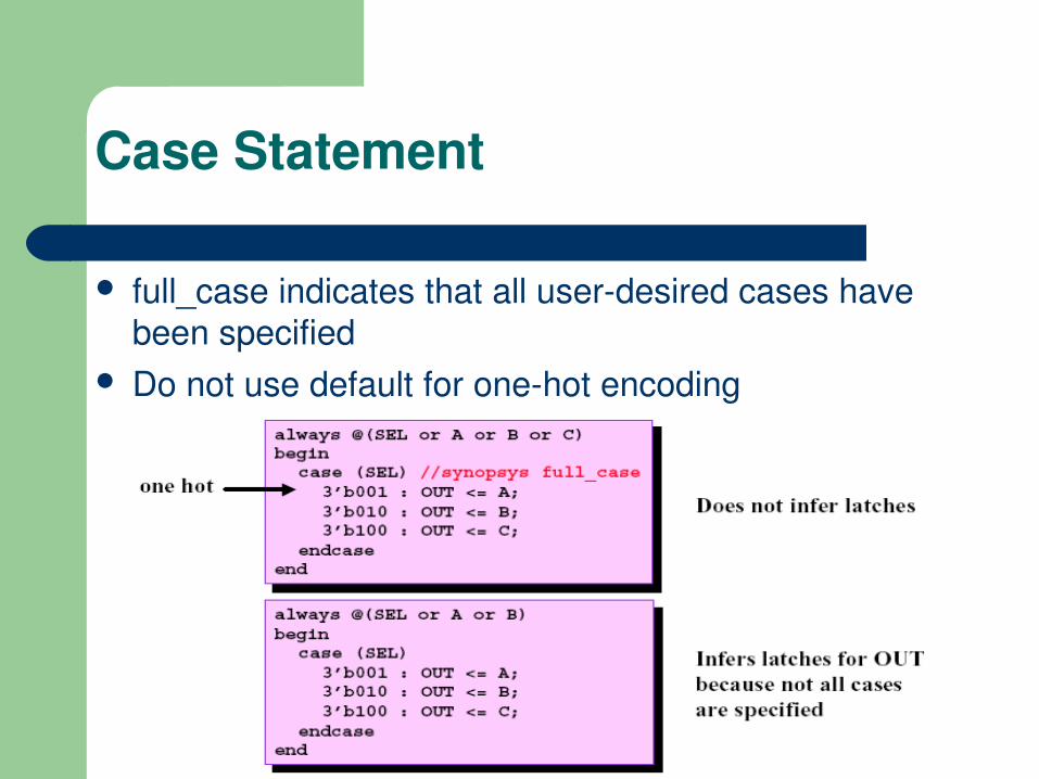
Case Statement
full_case indicates that all userdesired cases have been specified
Do not use default for onehot encoding
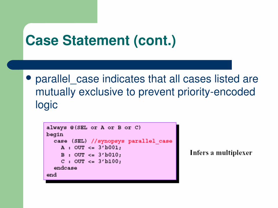
Case Statement (cont.)
parallel_case indicates that all cases listed are mutually exclusive to prevent priorityencoded logic

Case Statement (cont.)“CASE” vs. “IFTHENELSE”
Use IFELSE for 2to1 multiplexers Use CASE for nto1 multiplexers where n > 2 Use IFELSE IF for priority encoders Use CASE with //synopsys parallel_case when
conditions are mutually exclusive Use CASE with //synopsys full_case when not all
conditions are specified Use CASE with //synopsys full_case parallel_case for
onehot Finite State Machines (FSMs)
Case Statement (cont.)FSM encoding
Use CASE statements to describe FSMs Use //synopsys parallel_case to indicate
mutual exclusivity Use //synopsys full_case when not all possible
states are covered (onehot) Do not use default unless recovery state is
desired
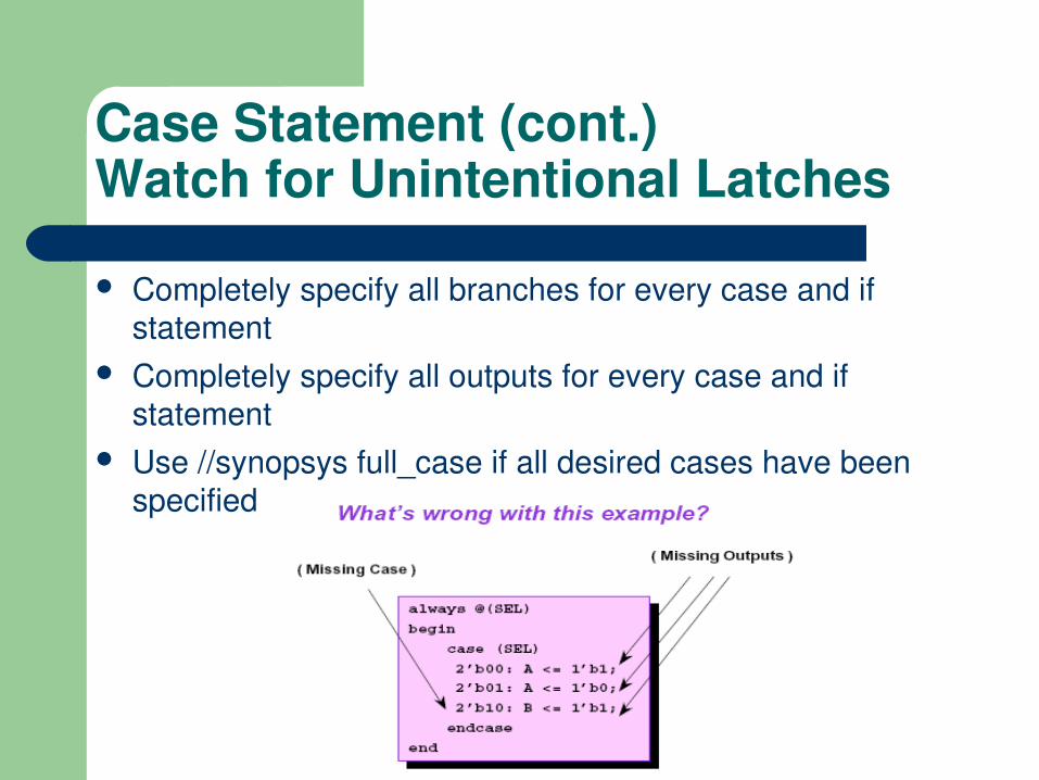
Case Statement (cont.)Watch for Unintentional Latches
Completely specify all branches for every case and if statement
Completely specify all outputs for every case and if statement
Use //synopsys full_case if all desired cases have been specified
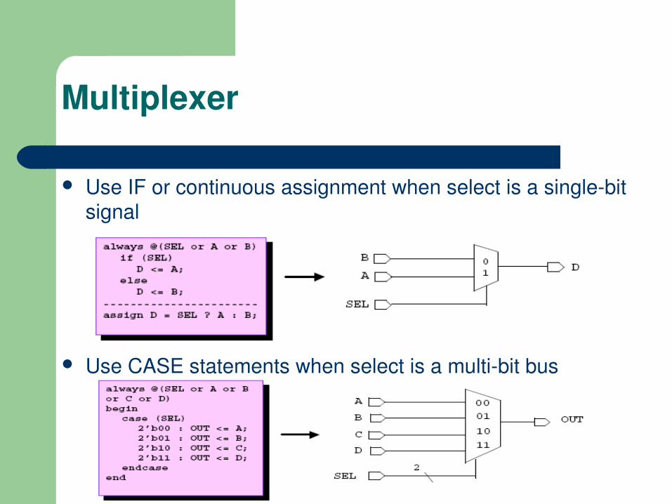
Multiplexer
Use IF or continuous assignment when select is a singlebit signal
Use CASE statements when select is a multibit bus

Operators
Operators inferred from HDL– Adder, Subtractor, AddSub (+, ), Multiplier (*)– Comparators (>, >=, <, <=, ==, !=)– Incrementer, Decrementer, IncDec (+1, 1)
Example
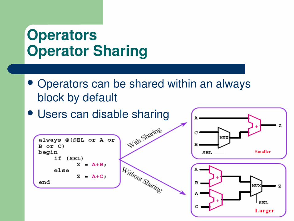
OperatorsOperator Sharing
Operators can be shared within an always block by default
Users can disable sharing

OperatorsOperator Balancing
Use parenthesis to guide synthesis
Sequential behaviorFinite State Machines
In the abstract, an FSM can be defined by:– A set of states or actions that the system will perform– The inputs to the FSM that will cause a sequence to occur– The outputs that the states (and possibly, the inputs) produce
There are also two special inputs– A clock event, sometimes called the sequencing event, that
causes the FSM to go from one state to the next– A reset event, that causes the FSM to go to a known state
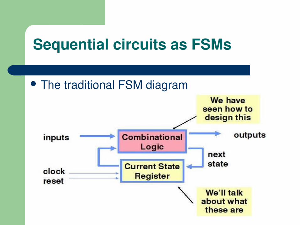
Sequential circuits as FSMs
The traditional FSM diagram
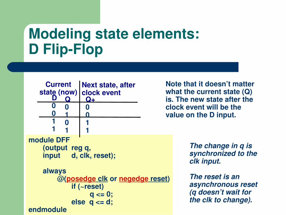
Modeling state elements:D FlipFlop
module DFF(output reg q,input d, clk, reset);
always@(posedge clk or negedge reset)
if (~reset) q <= 0;
else q <= d;endmodule
The change in q is synchronized to the clk input.
The reset is an asynchronous reset (q doesn’t wait for the clk to change).
Note that it doesn’t matter what the current state (Q) is. The new state after the clock event will be the value on the D input.
D0011
Next state, after clock event
Q0101
Q+0011
Current state (now)

Synchronous vs. Asynchronous reset
module ffsr(clk, reset, d, q);
// synchronous reset
input clk;
input reset;
input [3:0] d;
output [3:0] q;
reg [3:0] q;
always @(posedge clk)
if (reset) q <= 4’b0;
else q <= d;
endmodule
module ffar(clk, reset, d, q);
// asynchronous reset
input clk;
input reset;
input [3:0] d;
output [3:0] q;
reg [3:0] q;
always @(posedge clk or posedge reset)
if (reset) q <= 4’b0;
else q <= d;
endmoduleSynchronous reset (only upon clock edge)
Asynchronous reset

Putting it all together:RTL modeling syle
Things to note– reg [1:2] — matches
numbering in state assignment (Q2 is least significant bit in counting)
– <= vs. =
module FSM (x, z, clk, reset);input clk, reset, x;output z;reg [1:2] q, d;reg z;
endmodule
always @(x or q)begin
d[1] = q[1] & x | q[2] & x;d[2] = q[1] & x | ~q[2] & x;z = q[1] & q[2];
end
always@(posedge clk or negedge reset)
if (~reset) q <= 0;
else q <= d;The sequential part
(the D flip flop)
The combinational logic part
next state
output

FSMs with symbolic states
module divideby3FSM(clk, reset, out);
input clk;
input reset;
output out;
reg [1:0] state;
reg [1:0] nextstate;
// State Symbols
parameter S0 = 2’b00;
parameter S1 = 2’b01;
parameter S2 = 2’b10;
// State Register
always @(posedge clk)
if (reset) state <= S0;
else state <= nextstate;
// Continues…
// Next State Logic
always @(state)
case (state)
S0: nextstate = S1;
S1: nextstate = S2;
S2: nextstate = S0;
default: nextstate = S0;
endcase
// Output Logic
assign out = (state == S2);
endmodule

Nonblocking assignments and edgetriggered behavior
module counter(clk, reset, q);
input clk;
input reset;
output [3:0] q;
reg [3:0] q;
// counter using always block
always @(posedge clk)
if (reset) q <= 4’b0;
else q <= q+1;
endmodule
module shiftreg(clk, sin, q);
input clk;
input sin;
output [3:0] q;
reg [3:0] q;
always @(posedge clk)
begin
q[0] <= sin;
q[1] <= q[0];
q[2] <= q[1];
q[3] <= q[2];
// even better: q <= {q[2:0], sin};
end
endmodule
Synchronous counter
Synchronous shiftreg
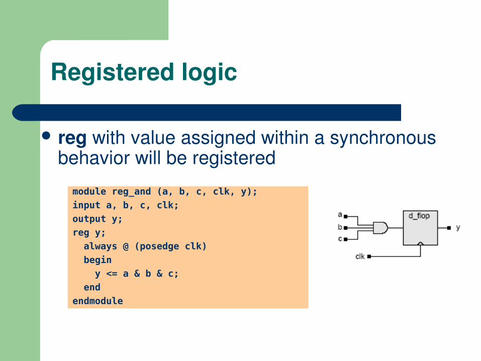
Registered logic
reg with value assigned within a synchronous behavior will be registered
module reg_and (a, b, c, clk, y);
input a, b, c, clk;
output y;
reg y;
always @ (posedge clk)
begin
y <= a & b & c;
end
endmodule
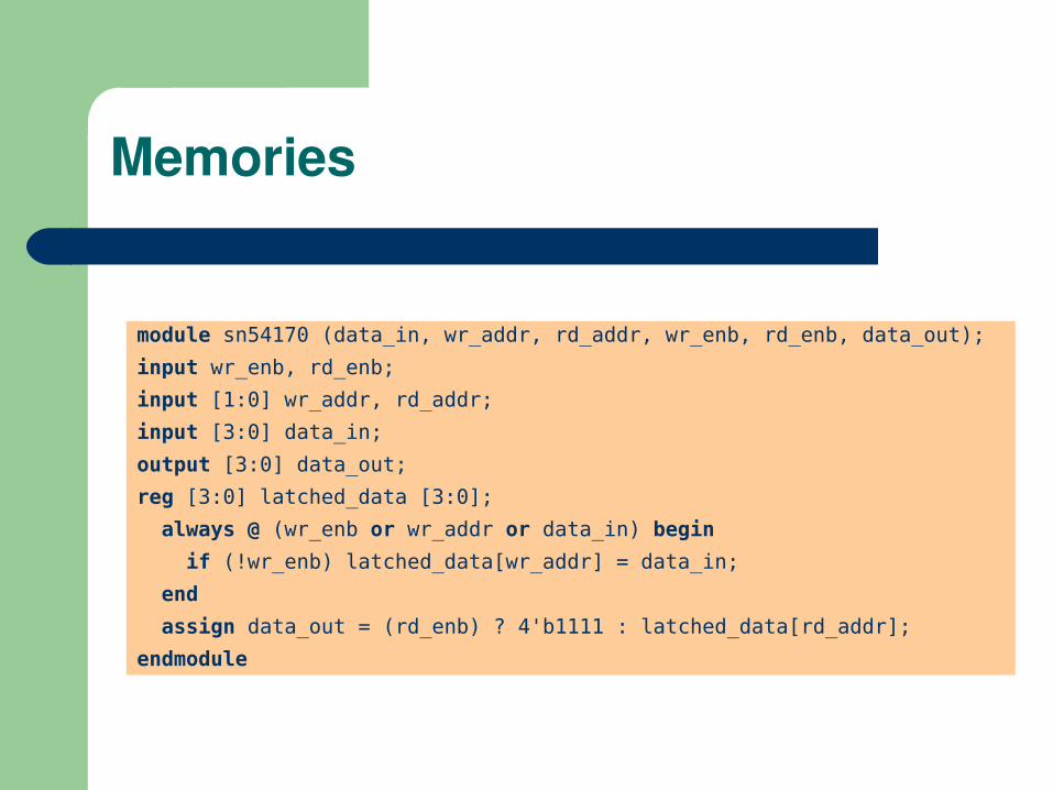
Memories
module sn54170 (data_in, wr_addr, rd_addr, wr_enb, rd_enb, data_out);
input wr_enb, rd_enb;
input [1:0] wr_addr, rd_addr;
input [3:0] data_in;
output [3:0] data_out;
reg [3:0] latched_data [3:0];
always @ (wr_enb or wr_addr or data_in) begin
if (!wr_enb) latched_data[wr_addr] = data_in;
end
assign data_out = (rd_enb) ? 4'b1111 : latched_data[rd_addr];
endmodule