Embed Size (px)
Citation preview
Verifying Parametrised Hardware Designsvia Counter Automata
A. Smrcka1 T. Vojnar1
1Faculty of Information TechnologyBrno University of Technology
Haifa Verification Conference 2007, Haifa, IL
Smrcka, Vojnar (FIT BUT, CZ) Hardware Design→ Counter Automaton
Outline
1 Motivation2 Basics of RTL design and VHDL3 Counter automata4 Transformation VHDL → counter automata5 Bad state specification6 Experiments + conclusions
Smrcka, Vojnar (FIT BUT, CZ) Hardware Design→ Counter Automaton
A Common Process of FV of HW Design
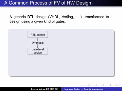
A generic RTL design (VHDL, Verilog, . . . ) transformed to adesign using a given kind of gates.
RTL design
synthesis
gate-leveldesign
Smrcka, Vojnar (FIT BUT, CZ) Hardware Design→ Counter Automaton

A Common Process of FV of HW Design
Transforming gate-level design into a hardware description.
RTL design
hardware
synthesis
gate-leveldesign
place & route
Smrcka, Vojnar (FIT BUT, CZ) Hardware Design→ Counter Automaton

A Common Process of FV of HW Design
Given a specification and a gate-level design we can performformal verification (MC on a finite state systems).
RTL design
hardware
Ok / bug
synthesis
gate-leveldesign
place & route
FV
Smrcka, Vojnar (FIT BUT, CZ) Hardware Design→ Counter Automaton

A Common Process of FV of HW Design
Problem with parametric/generic properties of design.Motivation: How to verify parametrised hardware design
RTL design
hardware
Ok / bug
synthesis
gate-leveldesign
place & route
FV
generic
concrete
Smrcka, Vojnar (FIT BUT, CZ) Hardware Design→ Counter Automaton
The Main Idea
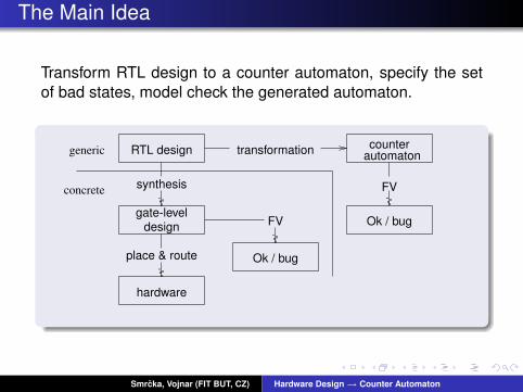
Transform RTL design to a counter automaton, specify the setof bad states, model check the generated automaton.
RTL design
hardware
Ok / bug
Ok / bug
counterautomaton
synthesis
gate-leveldesign
place & route
FV
transformation
FV
generic
concrete
Smrcka, Vojnar (FIT BUT, CZ) Hardware Design→ Counter Automaton
RTL Hardware Design
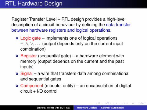
Register Transfer Level – RTL design provides a high-leveldescription of a circuit behaviour by defining the data transferbetween hardware registers and logical operations.
Logic gate – implements one of logical operations¬,∧,∨, . . . (output depends only on the current inputcombination)Register (sequential gate) – a hardware element withmemory (output depends on the current and the pastinputs)Signal – a wire that transfers data among combinationaland sequential gatesComponent (module, entity) – an encapsulation of digitalcircuit + I/O control
Smrcka, Vojnar (FIT BUT, CZ) Hardware Design→ Counter Automaton

Semantics of VHDL Constructs
Hardware design is described in a modular way.entity counter isgeneric ( max: integer );port (reset, clk: in std_logic;cnt: out std_logic_vector(32 downto 0);zf: out std_logic;
);end entity;architecture cnt_arch of counter isbeginprocess (reset, clk)beginif (reset=’1’) then cnt <= 0;elsif (clk’event and clk=’1’) then
if (cnt = max-1) then cnt <= 0;else cnt <= cnt+1;end if;
end if;end process;comp: entity comp32 port map ( cnt, 0, zf );
end;
clk
reset
cnt
zf
max
% max(cnt+1)cnt =
Smrcka, Vojnar (FIT BUT, CZ) Hardware Design→ Counter Automaton
Counter Automata
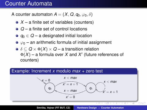
A counter automaton A = (X , Q, q0, ϕ0, δ)
X – a finite set of variables (counters)Q – a finite set of control locationsq0 ∈ Q – a designated initial locationϕ0 – an arithmetic formula of initial assignmentδ ⊆ Q × Φ(X )×Q – a transition relationΦ(X ) – a formula over X and X ′ (future references ofcounters)
Example: Increment x modulo max + zero test
"!#
"!# Z
ZZ
Z
x < max
x ′ = x + 1
x = max
x ′ = 0
x = 0
q0 q1x ′ = x + 1
x < max
Smrcka, Vojnar (FIT BUT, CZ) Hardware Design→ Counter Automaton

Intermediate Behavioural Model
A direct mapping from VHDL source code to counterautomaton is too complex → introduce an intermediatebehavioural model as the “bridge”.
RTL design counterautomaton
InterBM
Steps to produce a counter automaton:
1 Normalize the VHDL code of an RTL design2 Refine an intermediate behavioural model3 Build the counter automaton
Smrcka, Vojnar (FIT BUT, CZ) Hardware Design→ Counter Automaton

RTL Design :: Normalization of VHDL Code
Goal: obtain code using registered signals (1-bit type, bitvectors), behavioural description, assignment statement + ifstmt only
1 Variables of user defined structural types → more variablesof simple types (single bit, bit vectors).Bit vectors (constant size) accessed bitwise → more 1-bitsignals.Bitwise operations over parameter sized bit vectors →more complex arithmetic operations over bit vectors
2 Structural description → behavioural description (onlyprocess and assignment statements are allowed)
3 Non-registered signals → expressions over registeredsignals
4 Conditional assignments (with, case) → if statements
Smrcka, Vojnar (FIT BUT, CZ) Hardware Design→ Counter Automaton
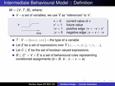
Intermediate Behavioural Model :: DefinitionM = (V , T , B), where:
V – a set of variables, we use V as “references” to V :
��v
time
v = 0 current value of vv ′ = 1 future value↑v = 1 positive edge ↑v = ¬v ∧ v ′
↓v = 0 negative edge ↓v = v ∧ ¬v
T : V → {bool,int} – the type of a variable
Let E be a set of expressions over V (+,−,=, 6=,≥,¬,∧, . . . ),
Let C ⊆ E be the set of boolean valued expressions.
B ⊆ C∗ × V × E is a set of behavioural rules representingconditioned assignments (b ∈ B, b : c → v := e)
res′ → addr := 0¬res′, ↑clk , (addr 6= max − 1) → addr := addr + 1¬res′, ↑clk , (addr = max − 1) → addr := 0
¬res′,¬↑clk → addr := addr
Smrcka, Vojnar (FIT BUT, CZ) Hardware Design→ Counter Automaton

Model :: Extracting from Source Code (1/2)
RTL designInterBM
counterautomaton
M = (V , T , B)
Variables V contain all registered signals + parametersT (v) = bool if v is 1-bit signal,T (v) = int if v is a bit vector or a parameterA VHDL expression: (clk’event and clk = ’1’)InterBM expression: ↑clk ∈ E
Smrcka, Vojnar (FIT BUT, CZ) Hardware Design→ Counter Automaton

Model :: Extracting from Source Code (2/2)
Behavioural rules: B ⊆ C∗ × V × E
Process if conditional statements such that every if setsthe value of only one state variable.From every if statement, create a tree of preconditionsand expressions of the next values (missing branchesrepresent no change of the variable value: v ′ = v ).
Example
if c1 thenv := e1;
elseif c2 then
v := e2;end if;
end if;
����
c1
e1����
c2
v e2
��
@@
��
@@
v ′ =0 1
0 1
c1 → v := e1¬c1, c2 → v := e2¬c1,¬c2 → v := v
Smrcka, Vojnar (FIT BUT, CZ) Hardware Design→ Counter Automaton

Model :: Environment
For model checking, we need to model the environment too.Environment = input signals of a component. Behaviour of theenvironment can be completely random representation of aninput:ε → v := random ∈ B for v ∈ V representing input signal.
Smrcka, Vojnar (FIT BUT, CZ) Hardware Design→ Counter Automaton
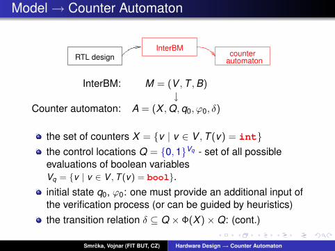
Model → Counter Automaton
RTL designInterBM
counterautomaton
InterBM: M = (V , T , B)↓
Counter automaton: A = (X , Q, q0, ϕ0, δ)
the set of counters X = {v | v ∈ V , T (v) = int}the control locations Q = {0, 1}Vq - set of all possibleevaluations of boolean variablesVq = {v | v ∈ V , T (v) = bool}.initial state q0, ϕ0: one must provide an additional input ofthe verification process (or can be guided by heuristics)the transition relation δ ⊆ Q × Φ(X )×Q: (cont.)
Smrcka, Vojnar (FIT BUT, CZ) Hardware Design→ Counter Automaton

Model → CA :: Transition Relation
1 δ := {}2 for q1, q2 in Q do3 actions := {}4 for (b : c → v := e) in B do5 if cq1,q2 6= 0 then6 actions := actions ∪ {(cq1,q2 , v ′ = eq1,q2)}7 δ := δ ∪ transitions(q1, actions, q2)
����
0 0 ����
0 1
¬c1 ∧ c2 ∧ a2
c1 ∧ ¬c2 ∧ a1
c1 ∧ c2 ∧ a1 ∧ a2����
����
0 10 0
x=0y=0
x’=0y’=1
q1 q2
actions = {(cq1,q21 , a1), (c
q1,q22 , a2)}
? (line 5)
lines 3-6
line 7
Smrcka, Vojnar (FIT BUT, CZ) Hardware Design→ Counter Automaton

Formal Verification :: Set of Bad States
Only safety properties are taken into account → specification ofbad state(s):
1 One defines the propositional formula over componentsignals defining the bad state – ebad
2 A control location qbad ∈ Q representing the bad states iscreated
3 From every control location, create a transition to qbad ifthere is possible true evaluation of ebad
for q in Q doif eq
bad 6= 0 then
δ := δ ∪ {(q, eqbad , qbad)}
Smrcka, Vojnar (FIT BUT, CZ) Hardware Design→ Counter Automaton
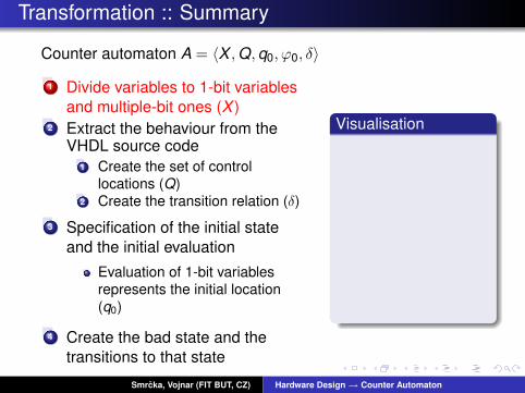
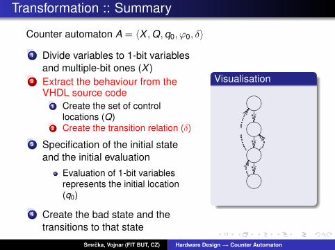
Transformation :: Summary
Counter automaton A = 〈X , Q, q0, ϕ0, δ〉
1 Divide variables to 1-bit variablesand multiple-bit ones (X )
2 Extract the behaviour from theVHDL source code
1 Create the set of controllocations (Q)
2 Create the transition relation (δ)
3 Specification of the initial stateand the initial evaluation
Evaluation of 1-bit variablesrepresents the initial location(q0)
4 Create the bad state and thetransitions to that state
Visualisation
Smrcka, Vojnar (FIT BUT, CZ) Hardware Design→ Counter Automaton
Transformation :: Summary
Counter automaton A = 〈X , Q, q0, ϕ0, δ〉
1 Divide variables to 1-bit variablesand multiple-bit ones (X )
2 Extract the behaviour from theVHDL source code
1 Create the set of controllocations (Q)
2 Create the transition relation (δ)
3 Specification of the initial stateand the initial evaluation
Evaluation of 1-bit variablesrepresents the initial location(q0)
4 Create the bad state and thetransitions to that state
Visualisation
� ��� ��� ��� ��
Smrcka, Vojnar (FIT BUT, CZ) Hardware Design→ Counter Automaton
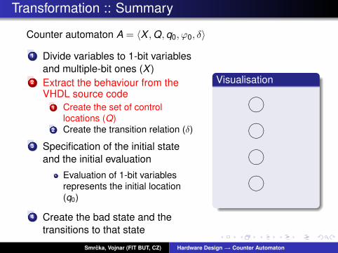

Transformation :: Summary
Counter automaton A = 〈X , Q, q0, ϕ0, δ〉
1 Divide variables to 1-bit variablesand multiple-bit ones (X )
2 Extract the behaviour from theVHDL source code
1 Create the set of controllocations (Q)
2 Create the transition relation (δ)
3 Specification of the initial stateand the initial evaluation
Evaluation of 1-bit variablesrepresents the initial location(q0)
4 Create the bad state and thetransitions to that state
Visualisation
� ��� ��� ��� ��
XXXXϕ0
Smrcka, Vojnar (FIT BUT, CZ) Hardware Design→ Counter Automaton

Transformation :: Summary
Counter automaton A = 〈X , Q, q0, ϕ0, δ〉
1 Divide variables to 1-bit variablesand multiple-bit ones (X )
2 Extract the behaviour from theVHDL source code
1 Create the set of controllocations (Q)
2 Create the transition relation (δ)
3 Specification of the initial stateand the initial evaluation
Evaluation of 1-bit variablesrepresents the initial location(q0)
4 Create the bad state and thetransitions to that state
Visualisation
� ��� ��� ��� ��
� ��XXXXZ
ZZ
ZZ
PPPPP
�����
��
��
�
ϕ0
Smrcka, Vojnar (FIT BUT, CZ) Hardware Design→ Counter Automaton

Formal Verification :: Experiments
Pentium4 2.8Ghz, 512MB, Python interpreter for translator.
Component |Q| |δ| |X | Trans. ARMC [1]Counter 5 13 1 < 1s < 1sRegister 9 45 1 1s < 1sSynLIFO 65 985 1 1m13s 2.7sAsFIFO (Status) 65 5484 11 3m51s 26m58sAsFIFO (FE) 65 5075 11 3m31s 1h17m
Safety properties like:bad = ¬RESET ∧ CLK ∧ EN ∧ (OUT 6= DATA)
[1] A. Podelski, A. Rybalchenko. ARMC: The Logical Choice forSoftware Model Checking with Abstraction Refinement. PADL 2007.
Smrcka, Vojnar (FIT BUT, CZ) Hardware Design→ Counter Automaton

Conclusions
We have proposed the method of FV of parametrised HWcomponents through the counter automata.Future work/ideas:
Reduction of a size of generated automatonAllow bit-wise operations on integers (often used in HWdesign)Experiments with more components and more tools
Smrcka, Vojnar (FIT BUT, CZ) Hardware Design→ Counter Automaton

Model :: Appendix A
Environment: In the case of T (v) = bool:ε → v := vε → v := ¬v
For a simpler construction of CA from InterBM,if T (v) = bool:
c → v := e =⇒ c, v ′ = e → v := eebad : using references to current variable values (with nov ′, ↑v , or ↓v reference)
Example of Behavioural rules
res′ → addr := 0¬res′, ↑clk , (addr 6= max − 1) → addr := addr + 1¬res′, ↑clk , (addr = max − 1) → addr := 0
¬res′,¬↑clk → addr := addr
Smrcka, Vojnar (FIT BUT, CZ) Hardware Design→ Counter Automaton
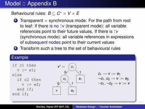
Model :: Appendix B
Behavioural rules: B ⊆ C∗ × V × E1 Transparent × synchronous mode: For the path from root
to leaf: If there is no ↑v (transparent mode): all variablereferences point to their future values. If there is ↑v(synchronous mode): all variable references in expressionsof subsequent nodes point to their current values
2 Transform such a tree to the set of behavioural rules
Example
if c1 thenv := e1;
elseif c2 then
v := e2;end if;
end if;
����
c1
e1����
c2
v e2
��
@@
��
@@
v ′ =0 1
0 1
c1 → v := e1¬c1, c2 → v := e2¬c1,¬c2 → v := v
Smrcka, Vojnar (FIT BUT, CZ) Hardware Design→ Counter Automaton