Embed Size (px)
Citation preview
28TH
INTERNATIONAL CONGRESS OF THE AERONAUTICAL SCIENCES
1
Abstract
This paper describes the development results
of optical telescope CFRP structure with
analysis and qualification test.
Structural analysis and space qualification
tests were carried out with launch and in-orbit
environments in order to verify the optical
payload CFRP structure for satellite with
optical, structural and dimensional stability
point of view.
And structural stability is verified by coupon
tests with statistical analysis for calculation
Margin of Safety (MoS). Structural analysis
with design load and modal analysis in order to
prevent the dynamic coupling were performed.
And thermo-elastic analysis with qualification
temperature from on-orbit thermal analysis
results was performed to verify the structural
stability. After performed the analytical
verification, space qualification tests with
structural model(SM) were carried out with
dynamic test (sin and random vibration test &
sin burst (design load) test) and thermal cycle
test for on-orbit structural stability. Optical
performance (WFE: Wave front Error) with
optics mounted on CFRP Bezel, structural
stability with modal survey and 3-dimensional
measurement with CMM were performed before
and after the space qualification tests.
1 Introduction
Structure of space usage like satellite bus,
payload telescope etc, was exposed by the
launch environment from launcher system like
acoustic, vibration, shock etc. And on orbit
environment, structure should endure
temperature change. Also structure should
provide the dimensional stability for the
optical performance in operation temperature
range.
So high-modulus carbon fiber with Cyanate
ester resin was chosen with Aluminum
honeycomb core and invar. Stacking sequence
design of using uni-directional lamina was
performed for structure, thermal and optical
requirements. After design the stacking
sequence, laminate properties were verified
with coupon test.
CFRP optical structure design was verified
with analysis (modal, strength with design load,
random vibration, distortion for optical
performance and thermal elastic analysis)
using coupon test results and qualification test
(sin, random, shock and thermal cycle test).
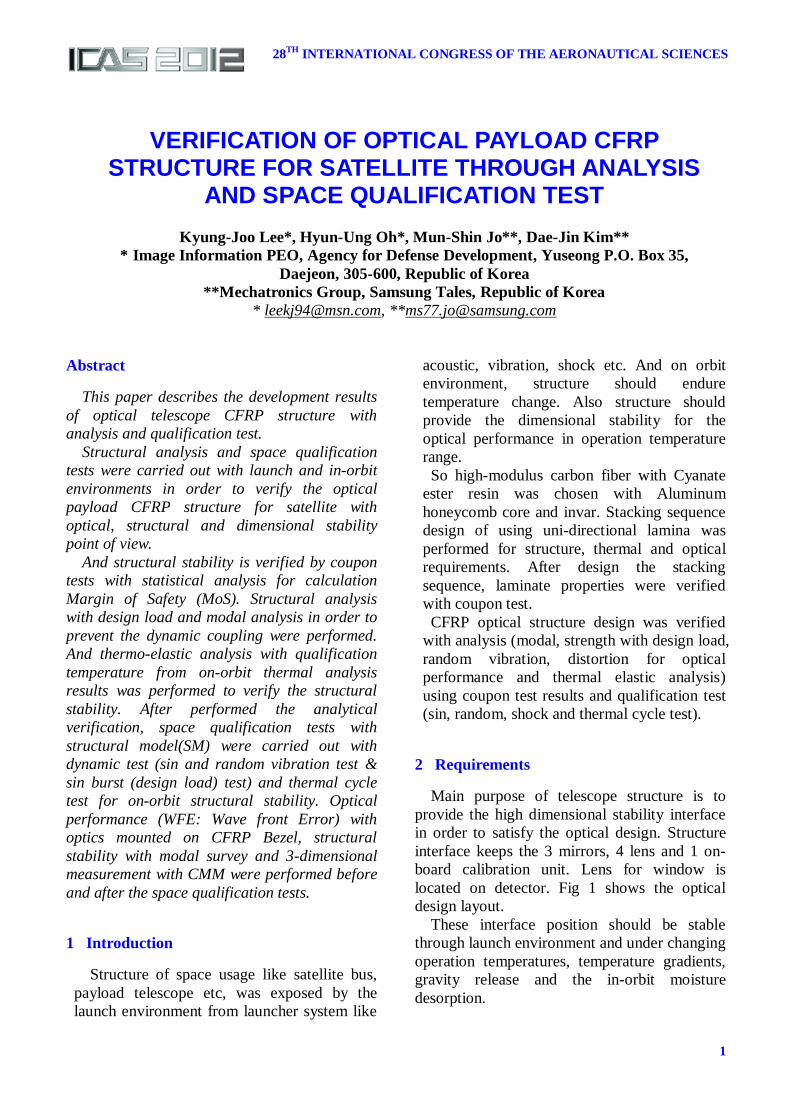
2 Requirements
Main purpose of telescope structure is to
provide the high dimensional stability interface
in order to satisfy the optical design. Structure
interface keeps the 3 mirrors, 4 lens and 1 on-
board calibration unit. Lens for window is
located on detector. Fig 1 shows the optical
design layout.
These interface position should be stable
through launch environment and under changing
operation temperatures, temperature gradients,
gravity release and the in-orbit moisture
desorption.
VERIFICATION OF OPTICAL PAYLOAD CFRP STRUCTURE FOR SATELLITE THROUGH ANALYSIS
AND SPACE QUALIFICATION TEST
Kyung-Joo Lee*, Hyun-Ung Oh*, Mun-Shin Jo**, Dae-Jin Kim**
* Image Information PEO, Agency for Defense Development, Yuseong P.O. Box 35,
Daejeon, 305-600, Republic of Korea
**Mechatronics Group, Samsung Tales, Republic of Korea
* [email protected], **[email protected]
Keywords: keywords list (no more than 5)
KYUNG-JOO LEE, HYUN-UNG OH, MUN-SHIN JO, DAE-JIN KIM
2
Fig. 1. Optical Design Layout
In order to design the optical telescope
structure, requirements were considered with
following items with launch and in-orbit
condition.
Stiffness requirement is for avoiding the
dynamic coupling with upper system and design
load with quasi-static load is generally from
MAC(Mass Acceleration Curve) at initial
design phase. Temperature range for structure
safety by thermal elastic analysis is from
satellite level system orbit thermal analysis and
is defined the survival temperature to
qualification temperature
Mass : < 31.5kg
Envelop : 880mm x 860mm x 760mm
1st frequency(Stiffness) : > 120Hz
Design Load : 25g
Qual. Temperature range : -15~50oC
Optical requirements at in-orbit operation
condition were defined with wave-front error
(WFE) below 31.71nmrms from optical
sensitivity analysis with following operation
condition. Table 1 shows the in-orbit optical
requirements with each environmental condition.
Table 1 In-orbit requirements
In-orbit Condition Requirement
Uniform Temperature
Change 12K
13.2 nmrms Temperature
Gradients 1K
X
Y
Z
Gravity Release X 28.4 nmrms
1g Y
Z
Moisture Desorption 5 nmrms
Total 31.71 nmrms
In launch condition, structure meets the
vibration and shock environment. Vibration
conditions are sinusoidal and random load.
Shock load is from satellite separation mainly.
Table 2~4 show that sine, random vibration
and shock environmental condition. These
launch environments applied to the vibration
analysis and qualification test.
Table 2 Sine vibration requirement
Table 3 Random vibration requirement
Table 4 Shock requirement
X, Y Axis (Lateral) Z Axis (Axial)
Frequency (Hz)
Qual.
Accel.
(g)
Frequency (Hz)
Qual.
Accel.
(g)
5 ~ 12 ± 8mm 5~16 ± 9.2mm
12 ~ 30 6.5 g 16~ 50 9.0 g
30 ~ 100 3.0 g 50 ~ 100 6.5 g
Frequency
(Hz)
Qualification PSD
(g2/Hz)
Remarks
20 0.014 Duration
Acceptance : 1 min
Qualification:
2min
All Axis(x,y,z)
70 0.05
700 0.05
2000 0.014
Overall 8.2Grms
Frequency
(Hz)
SRS
(g) Remark
100 8
1515 270
10000 270
Qualification = 2 Actuations, Q=10
3
VERIFICATION OF OPTICAL PAYLOAD CFRP STRUCTURE FOR
SATELLITE THROUGH ANALYSIS AND SPACE QUALIFICATION TEST
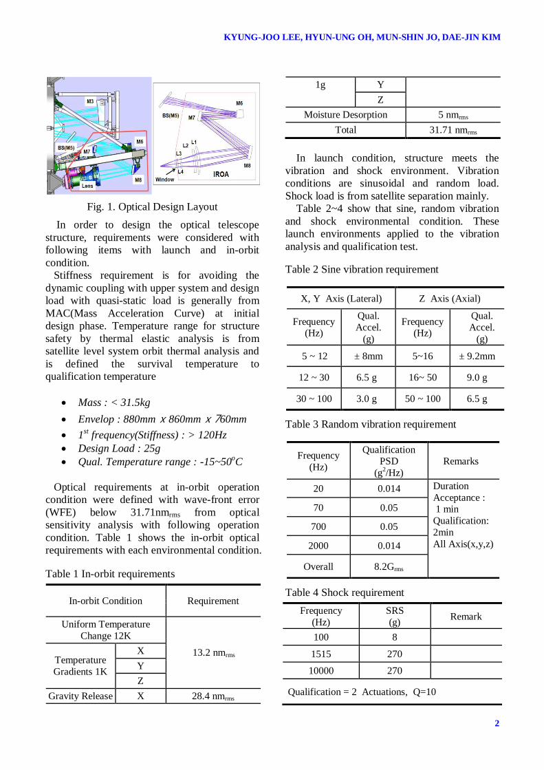
2.2 Configuration Design
Figure 2 shows the configuration of CFRP
optical telescope structure for verification with
qualification level.
Fig. 2. Configuration of Structure
CFRP optical telescope structure was to be
composed with 1 bezel and 2 trusses. Bezel was
making up to CFRP facesheet and Al core for
mounting optical components, detector and on-
boards unit. In the bezel, high précised tolerance
inserts were located to align the optical
components based on optical sensitivity and
tolerance analyses for assembly and alignment.
Each inserts were met the Invar shims for the
alignment.
Trusses were used to meet the eigen-
frequency requirement to increase the stiffness
of bezel. Truss was composed with CFRP and
Invar fittings applied for athermalization design
to prevent thermal stress.
Bezel and truss had a vent hole to prevent the
debonding at vacuum condition.
2.3 Material Selection
Fiber was selected to Toray M55J Ultra-High
Modulus fiber by trade-off study in order to
satisfy the frequency requirement (Young’s
modulus for Stiffness) and optical requirement
(dimensionally stable CTE (Coefficient of
Thermal Expansion) at operation temperature).
Resin was selected the Cyanate ester with
considered to minimize the moisture desorption
deformation at space vacuum environment.
Aluminum honeycomb core was selected the
porosity type to avoid the defect or delamination
when changing pressure to vacuum. Core type is
3/16 in Al5056 with considered compressive
and shear mechanical properties..
Aluminum insert was chosen to Al7075
T7351 to prevent the SCC(Stress Corrosion
Cracking).
Invar for end fitting parts is Invar36 and
Titanium was selected for thermal isolation.
Polymers like film adhesive FM73M for
bonding between CFRP and Al core, adhesive
EA9394 for CFRP to Invar fitting, and potting
compound STYCASE 2651 for Al insert
fixation were selected to consider the out-
gassing requirement to TML(Total Mass Loss)
< 1% and CVCM(Collected Volatile
Condensable Materials) < 0.1%.
2.4 CFRP Stacking Angle Design
Stacking angle design was performed to be
based on the selected CFRP uni-direction
lamina ply properties using CLT (Classical
Laminate Theory).
After calculating the laminate properties like
young’s modulus, shear modulus, CTE and
CME using CLT with M55J and Cyanate ester
resin, coupon test was done to verify the
laminate properties.
Coupon test’s results also were used to do the
modal, structural stability and distortion
analysis.
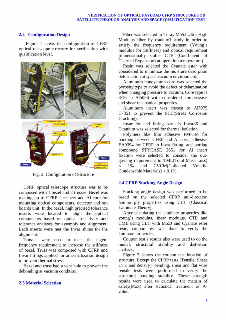
Figure 3 shows the coupon test location of
structure. Except the CFRP tests (Tensile, Shear,
CTE and density), bending, shear and flat wise
tensile tests were performed to verify the
structural bonding stability. These strength
results were used to calculate the margin of
safety(MoS) after statistical treatment of A-
value.
KYUNG-JOO LEE, HYUN-UNG OH, MUN-SHIN JO, DAE-JIN KIM
4
Fig. 3. Coupon test location
Table 5 and 6 show the laminate properties
of facesheet on bezel and tube on truss. When
calculating the maximum moisture strains with
CME, TML was considered to 0.3%. When
doing the TML and CVCM coupon test, TML
was lower than 0.1%. So CME did not be tested.
Table 5 Laminate properties of facesheet in
bezel.
Material Properties Unit CLT Coupon Test
Result
Young’s Modulus
E11 MPa 171400 173700
E22 MPa 38500 35700
Poisson’s Ratio
v12 - 0.873
Shear Modulus
G12 MPa 43000 85977
G23 MPa 2600 61501
G13 MPa 3700
CTE α1 1/K -1.33E-06 -1.29E-06
α2 1/K 2.26E-06 2.89E-06
Density ρ Kg/ cm³
1608 1600
Max. Moisture Strain (CME)
ε1 - -2.188E-06
(-6.564E-07) -
ε2 - 2.312E-04
(6.936E-05) -
Table 6 Laminate properties of tube in truss
Material Properties Unit CLT Coupon Test
Result
Young’s Modulus
E11 MPa 157600 152856
E22 MPa 64100 60400
Poisson’s Ratio
v12 - 0.554
Shear Modulus
G12 Mpa 43100 49159
G23 MPa 2800 51986
G13 MPa 3500
CTE α1 1/K -9.612E-07 -1.17E-06
α2 1/K 6.96E-07 1.71E-06
Density ρ Kg/ cm³
1608 1600
Max. Moisture Strain (CME)
ε1 - 2.2E-05
(6.6E-06) -
ε2 - 1.294E-04
(3.882E-05) -
2.5 Analysis
In order to verify the requirement using
analysis, analyses were performed to following
contents.
Structure Analysis
o Modal Analysis
o Quasi-static load Analysis
o Thermal Elastic Analysis
Vibration Analysis
Distortion Analysis
o 1K uniform temperature change
o 1K gradient temperature change
o 1g gravity release
o Moisture release
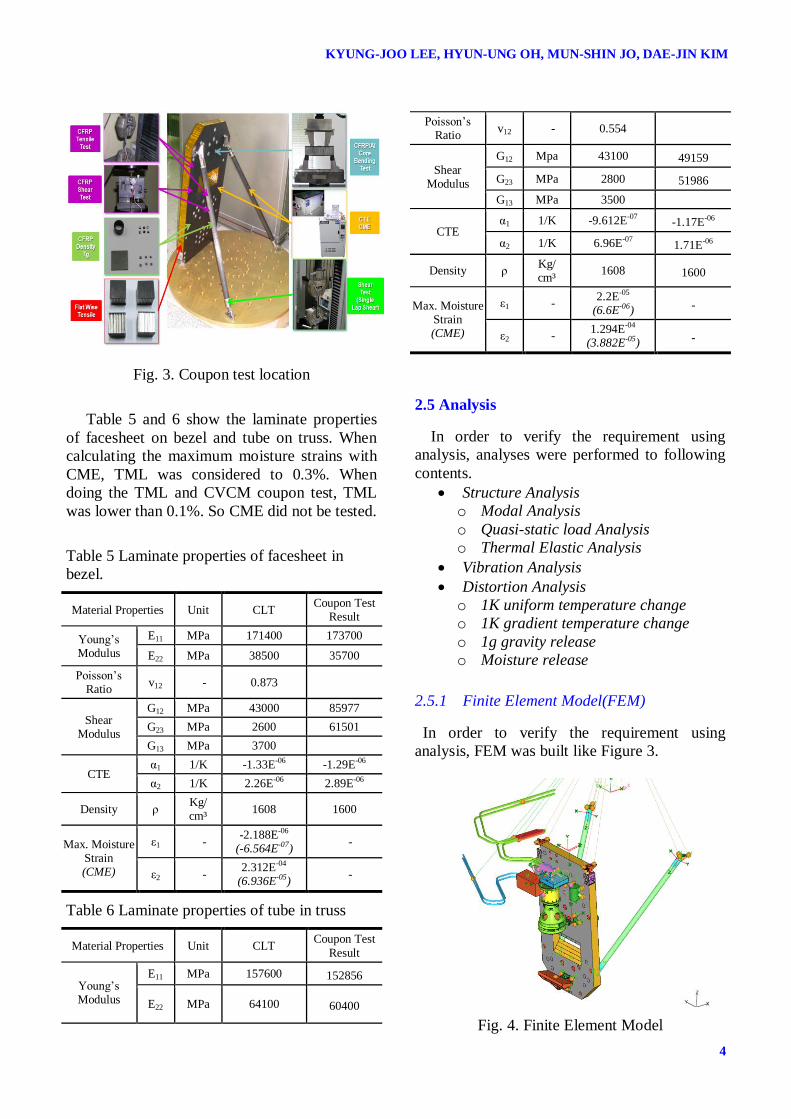
2.5.1 Finite Element Model(FEM)
In order to verify the requirement using
analysis, FEM was built like Figure 3.
Fig. 4. Finite Element Model
5
VERIFICATION OF OPTICAL PAYLOAD CFRP STRUCTURE FOR
SATELLITE THROUGH ANALYSIS AND SPACE QUALIFICATION TEST
At initial phase of design, FEM was composed
with rumpled mass of mounting components.
After done critical design, very fine mesh was
used to analyze the optical component’s surface
error at nano-meter unit level.
2.5.2 Modal Analysis
In order to verify the stiffness requirement
over 120Hz, modal analysis was performed.
(a) 1st Mode (Rotation) (b) 2
nd Mode (Bending)
Fig. 5. Modal analysis results
1st frequency is 137.8Hz with torsion mode
and 2nd
frequency is 148.9 Hz with bending
mode. Figure 4 shows the modal analysis results.
2.5.3 Strength Analysis
Quasi-static load (Design load) and thermal
elastic analyses were performed to verify the
structural stability. Requirement is MoS>0. In
equation 1, allowable stresses were used from
coupon test results. Applied safety factor (SF) is
like following.
(1)
Applied Safety Factor (SF):
Metallic Materials Yield = 1.25
Metallic Materials Ultimate = 1.4
CFRP Ultimate = 2.0
Adhesive Bonded Junction = 2.0
Inserts and Joints Yield =1.5
Inserts and Joints Ultimate = 2.0
Joints gapping and slipping =1.15
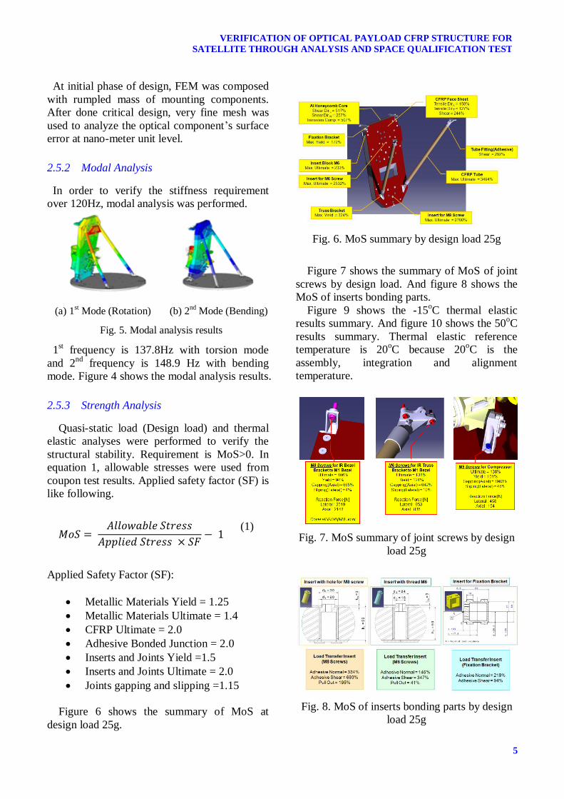
Figure 6 shows the summary of MoS at
design load 25g.
Fig. 6. MoS summary by design load 25g
Figure 7 shows the summary of MoS of joint
screws by design load. And figure 8 shows the
MoS of inserts bonding parts.
Figure 9 shows the -15oC thermal elastic
results summary. And figure 10 shows the 50oC
results summary. Thermal elastic reference
temperature is 20oC because 20
oC is the
assembly, integration and alignment
temperature.
Fig. 7. MoS summary of joint screws by design
load 25g
Fig. 8. MoS of inserts bonding parts by design
load 25g
KYUNG-JOO LEE, HYUN-UNG OH, MUN-SHIN JO, DAE-JIN KIM
6
Fig. 9. MoS summary of thermo-elastic analysis
of -15oC
Fig. 10. MoS summary of thermo-elastic
analysis of -50oC
For the structural stability point of view,
structure can be endured at launch and in-orbit
thermal condition with analytic method.
2.5.4 Vibration Analysis
In early design phase, conservative design
load from MAC was used for checking the
structural safety. After finished the detail design,
structural stability should be checked by
dynamic analysis because dynamic load may be
greater than static design load and cause the
coupling with each components.
And the other object of vibration analysis is
the prediction of notching profile to prevent
over-test at vibration test.
Because CFRP Structure stiffness
requirement and modal analysis results gave the
over 100Hz, random vibration analysis was
performed except sine vibration at lower
frequency excitation.
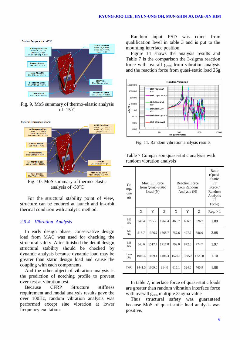
Random input PSD was come from
qualification level in table 3 and is put to the
mounting interface position.
Figure 11 shows the analysis results and
Table 7 is the comparison the 3-sigma reaction
force with overall grms from vibration analysis
and the reaction force from quasi-static load 25g.
Fig. 11. Random vibration analysis results
Table 7 Comparison quasi-static analysis with
random vibration analysis
Co
mp-onents
Max. I/F Force from Quasi-Static
Load (N)
Reaction Force from Random
Analysis (N)
Ratio (Quasi-Static
I/F Force /
Random Analysis
I/F Force)
X Y Z X Y Z Req. > 1
M6
SA 746.4 795.2 1262.4 465.7 666.3 626.7 1.89
M7
SA 518.7 1376.2 1568.7 752.6 497.7 586.0 2.08
M8
SA 543.6 1517.4 1717.8 799.0 872.6 774.7 1.97
Lens
SA 1900.4 1099.4 1406.3 1570.1 1095.8 1720.0 1.10
TMU 1441.5 1009.0 314.0 615.1 524.6 765.9 1.88
In table 7, interface force of quasi-static loads
are greater than random vibration interface force
with overall grms multiple 3sigma value
Thus structural safety was guaranteed
because MoS of quasi-static load analysis was
positive.
Random Vibration
0.00
0.01
0.10
1.00
10.00
100.00
1000.00
10000.00
1 10 100 1000 10000Frequency (Hz)
(m/s
2)2
/Hz
Bzl Top Mid
Ctr
Bzl Top Lwr Ctr
Bzl Btm Mid
Ctr
Bzl Btm Lwr
Ctr
Bzl Btm Upr Ctr
Ref. (Q Level)
7
VERIFICATION OF OPTICAL PAYLOAD CFRP STRUCTURE FOR
SATELLITE THROUGH ANALYSIS AND SPACE QUALIFICATION TEST
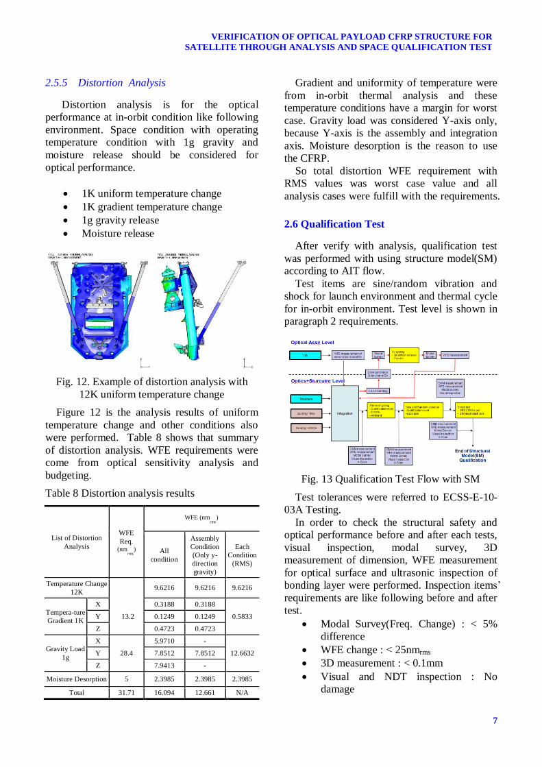
2.5.5 Distortion Analysis
Distortion analysis is for the optical
performance at in-orbit condition like following
environment. Space condition with operating
temperature condition with 1g gravity and
moisture release should be considered for
optical performance.
1K uniform temperature change
1K gradient temperature change
1g gravity release
Moisture release
Fig. 12. Example of distortion analysis with
12K uniform temperature change
Figure 12 is the analysis results of uniform
temperature change and other conditions also
were performed. Table 8 shows that summary
of distortion analysis. WFE requirements were
come from optical sensitivity analysis and
budgeting.
Table 8 Distortion analysis results
Gradient and uniformity of temperature were
from in-orbit thermal analysis and these
temperature conditions have a margin for worst
case. Gravity load was considered Y-axis only,
because Y-axis is the assembly and integration
axis. Moisture desorption is the reason to use
the CFRP.
So total distortion WFE requirement with
RMS values was worst case value and all
analysis cases were fulfill with the requirements.
2.6 Qualification Test
After verify with analysis, qualification test
was performed with using structure model(SM)
according to AIT flow.
Test items are sine/random vibration and
shock for launch environment and thermal cycle
for in-orbit environment. Test level is shown in
paragraph 2 requirements.
Fig. 13 Qualification Test Flow with SM
Test tolerances were referred to ECSS-E-10-
03A Testing.
In order to check the structural safety and
optical performance before and after each tests,
visual inspection, modal survey, 3D
measurement of dimension, WFE measurement
for optical surface and ultrasonic inspection of
bonding layer were performed. Inspection items’
requirements are like following before and after
test.
Modal Survey(Freq. Change) : < 5%
difference
WFE change : < 25nmrms
3D measurement : < 0.1mm
Visual and NDT inspection : No
damage
List of Distortion
Analysis
WFE
Req. (nm
rms)
WFE (nmrms
)
All
condition
Assembly
Condition
(Only y-
direction
gravity)
Each
Condition
(RMS)
Temperature Change
12K 9.6216 9.6216 9.6216
Tempera-ture
Gradient 1K
X
13.2
0.3188 0.3188
0.5833 Y 0.1249 0.1249
Z 0.4723 0.4723
Gravity Load
1g
X
28.4
5.9710 -
12.6632 Y 7.8512 7.8512
Z 7.9413 -
Moisture Desorption 5 2.3985 2.3985 2.3985
Total 31.71 16.094 12.661 N/A
KYUNG-JOO LEE, HYUN-UNG OH, MUN-SHIN JO, DAE-JIN KIM
8
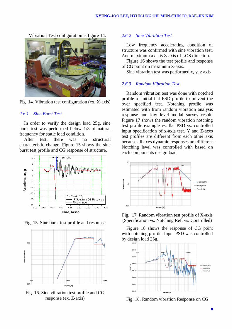
Vibration Test configuration is figure 14.
Fig. 14. Vibration test configuration (ex. X-axis)
2.6.1 Sine Burst Test
In order to verify the design load 25g, sine
burst test was performed below 1/3 of natural
frequency for static load condition.
After test, there was no structural
characteristic change. Figure 15 shows the sine
burst test profile and CG response of structure.
Fig. 15. Sine burst test profile and response
Fig. 16. Sine vibration test profile and CG
response (ex. Z-axis)
2.6.2 Sine Vibration Test
Low frequency accelerating condition of
structure was confirmed with sine vibration test.
And maximum axis is Z-axis of LOS direction.
Figure 16 shows the test profile and response
of CG point on maximum Z-axis.
Sine vibration test was performed x, y, z axis
2.6.3 Random Vibration Test
Random vibration test was done with notched
profile of initial flat PSD profile to prevent the
over specified test. Notching profile was
estimated with from random vibration analysis
response and low level modal survey result.
Figure 17 shows the random vibration notching
test profile example vs. flat PSD vs. controlled
input specification of x-axis test. Y and Z-axes
test profiles are different from each other axis
because all axes dynamic responses are different.
Notching level was controlled with based on
each components design load
Fig. 17. Random vibration test profile of X-axis
(Specification vs. Notching Ref. vs. Controlled)
Figure 18 shows the response of CG point
with notching profile. Input PSD was controlled
by design load 25g.
Fig. 18. Random vibration Response on CG
9
VERIFICATION OF OPTICAL PAYLOAD CFRP STRUCTURE FOR
SATELLITE THROUGH ANALYSIS AND SPACE QUALIFICATION TEST
2.6.4 Shock Test
For the shock environmental qualification test,
2 actuations were done with 270g SRS. Figure
19 shows the controlled input SRS and CG
response with test tolerance ±6dB.
100 1000 10000
10
100
SR
S (
g)
Freq. (Hz)
1st Test (C01Y)
1st Test (C02Y)
2nd Test (C01Y)
2nd Test (C02Y)
Test Spec
Test Tol (+6dB)
Test Tol (-6dB)
SM Shock Test (Y-axis) : Test Spec & Control (C01, C02)
Fig. 19. Shock test profile and CG response.
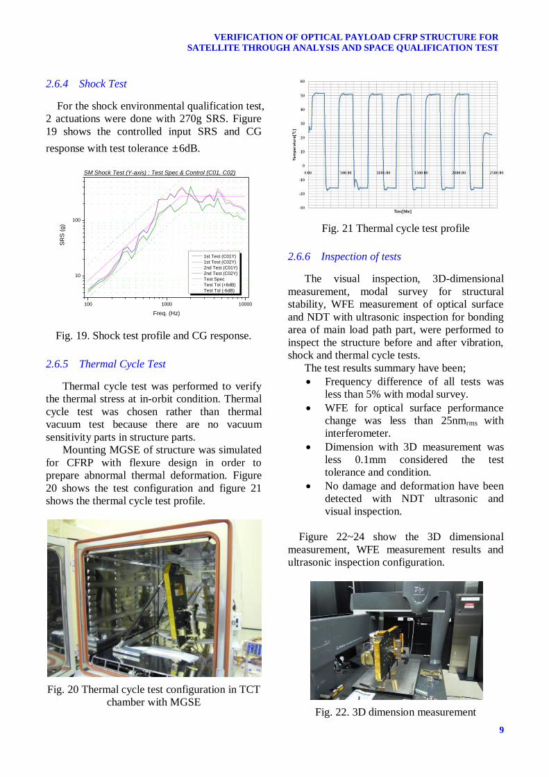
2.6.5 Thermal Cycle Test
Thermal cycle test was performed to verify
the thermal stress at in-orbit condition. Thermal
cycle test was chosen rather than thermal
vacuum test because there are no vacuum
sensitivity parts in structure parts.
Mounting MGSE of structure was simulated
for CFRP with flexure design in order to
prepare abnormal thermal deformation. Figure
20 shows the test configuration and figure 21
shows the thermal cycle test profile.
Fig. 20 Thermal cycle test configuration in TCT
chamber with MGSE
Fig. 21 Thermal cycle test profile
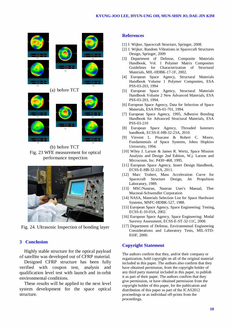
2.6.6 Inspection of tests
The visual inspection, 3D-dimensional
measurement, modal survey for structural
stability, WFE measurement of optical surface
and NDT with ultrasonic inspection for bonding
area of main load path part, were performed to
inspect the structure before and after vibration,
shock and thermal cycle tests.
The test results summary have been;
Frequency difference of all tests was
less than 5% with modal survey.
WFE for optical surface performance
change was less than 25nmrms with
interferometer.
Dimension with 3D measurement was
less 0.1mm considered the test
tolerance and condition.
No damage and deformation have been
detected with NDT ultrasonic and
visual inspection.
Figure 22~24 show the 3D dimensional
measurement, WFE measurement results and
ultrasonic inspection configuration.
Fig. 22. 3D dimension measurement
KYUNG-JOO LEE, HYUN-UNG OH, MUN-SHIN JO, DAE-JIN KIM
10
(a) before TCT
(b) before TCT
Fig. 23 WFE measurement for optical
performance inspection
Fig. 24. Ultrasonic Inspection of bonding layer
3 Conclusion
Highly stable structure for the optical payload
of satellite was developed out of CFRP material.
Designed CFRP structure has been fully
verified with coupon test, analysis and
qualification level test with launch and in-orbit
environmental conditions.
These results will be applied to the next level
system development for the space optical
structure.
References
[1] J. Wijker, Spacecraft Structure, Springer, 2008.
[2] J. Wijker, Random Vibrations in Spacecraft Structures
Design, Springer, 2009
[3] Department of Defense, Composite Materials
Handbook, Vol. 1 Polymer Matrix Composites Guidelines for Characterization of Structural
Materials, MIL-HDBK-17-1F, 2002.
[4] European Space Agency, Structural Materials
Handbook Volume 1 Polymer Composites, ESA
PSS-03-203, 1994
[5] European Space Agency, Structural Materials
Handbook Volume 2 New Advanced Materials, ESA
PSS-03-203, 1994.
[6] European Space Agency, Data for Selection of Space
Materials, ESA PSS-01-701, 1994.
[7] European Space Agency, 1995, Adhesive Bonding
Handbook for Advanced Structural Materials, ESA
PSS-03-210
[8] European Space Agency, Threaded fasteners
handbook, ECSS-E-HB-32-23A, 2010.
[9] Vinvent L. Pisacane & Robert C. Moore,
Fundamentals of Space Systems, Johns Hopkins
University, 1994.
[10] Wiley J. Larson & James R. Wertz, Space Mission
Analysis and Design 2nd Edition, W.j. Larson and
Microcosm, Inc. P430~468, 1995.
[11] European Space Agency, Insert Design Handbook,
ECSS-E-HB-32-22A, 2011.
[12] Marc Trubert, Mass Acceleration Curve for
Spacecraft Structure Design, Jet Propulsion
Laboratory, 1989.
[13] MSC/Nastran, Nastran User's Manual, Ther
Macneal-Schwendler Corporation
[14] NASA, Materials Selection List for Space Hardware
Systems, MSFC-HDBK-527, 1988.
[15] European Space Agency, Space Engineering: Testing,
ECSS-E-10-03A, 2002.
[16] European Space Agency, Space Engineering: Modal
Surevey Assessment, ECSS-E-ST-32-11C, 2008.
[17] Department of Defense, Environmental Engineering
Considerations and Laboratory Tests, MIL-STD-
810F, 2000.
Copyright Statement
The authors confirm that they, and/or their company or
organization, hold copyright on all of the original material
included in this paper. The authors also confirm that they
have obtained permission, from the copyright holder of
any third party material included in this paper, to publish
it as part of their paper. The authors confirm that they give permission, or have obtained permission from the
copyright holder of this paper, for the publication and
distribution of this paper as part of the ICAS2012
proceedings or as individual off-prints from the
proceedings.