Embed Size (px)
Citation preview
Document No. VWSP-500-01 February 2018 Rev. 01
User Manual
Ventway Sparrow Emergency and transport
ventilator
Ventway Sparrow User Manual
Page 2 of 93
Important
This User Manual is subject to periodic review, update and revision.
Do not use a defective product. Do not repair this product or any of its parts.
If this device does not perform properly, contact an Inovytec representative.
The user of this product has sole responsibility for any malfunction that
results from improper use, faulty maintenance, improper repair,
unauthorized service, damage, or alteration by anyone other than Inovytec
Medical Solutions Ltd.
The safety, reliability, and performance of this device can be assured only
under the following conditions:
• The device has been used according to the accompanying operating
instructions.
• All fittings, extensions, readjustments, changes, or repairs have been
carried out by Inovytec Medical Solutions Ltd.'s authorized
representatives.
No part of this publication may be reproduced, stored in a retrieval system or
transmitted in any form by any means, electronic, mechanical, photo
reproductive, recording or otherwise without the express prior written
permission of Inovytec Medical Solutions Ltd.
Inovytec Medical Solutions Ltd. reserves the right to change or improve its
products and accompanying technical literature without specific notice of
changes or improvements.
This product is protected by patents listed on the Inovytec website.
Ventway Sparrow User Manual
Page 3 of 93
Contact Information:
Inovytec Medical Solutions Ltd.
3 Hanagar St., POB 7282,
Hod-Hasharon 4501306, Israel
Tel: +972 9 779 41 35
Fax: +972 9 779 41 38
E-mail: [email protected]
Web Site: http://www.Inovytec.com
Disclaimer
Information provided by Inovytec Medical Solutions Ltd. is believed to be
accurate and reliable. However, Inovytec assumes no responsibility for the
use of such information, nor for any infringements of patents or other
rights of third parties, that may result from its use.
FDA Tracking Requirements
U.S. Federal Law (21 CFR 821) requires the tracking of ventilators. Under
this law, owners of this ventilator must notify Inovytec Medical Solutions
Ltd. if this product is received; lost, stolen, or destroyed; donated or resold;
or otherwise distributed to a different organization. If any such event
occurs, contact Inovytec in writing with the following information:
• Originator's organization – Company name, address, contact name, and contact phone number
• Model number, and serial number of the ventilator
• Disposition of the ventilator (for example, received, lost, stolen, destroyed, distributed to another organization), new location and/or organization (if known and different from originator’s organization) – company name, address, contact name, and contact phone number
• Date when the change took effect
Please address the information to Inovytec Medical Solutions Ltd. at the
address given above.
Ventway Sparrow User Manual
Page 4 of 93
CONTENTS
About This User Manual 8 1.1. TYPES OF WARNINGS, CAUTIONS AND NOTES 8 1.2. GLOSSARY AND ABBREVIATIONS 9
2. Overview of System 10 2.1. DESCRIPTION OF DEVICE 10
3. Conditions for Use 11 INTENDED USE 11 3.1. INDICATIONS FOR USE 11 3.2. CONTRAINDICATIONS 12 3.3. LIMITATIONS OF USE 12
4. Safety 13 4.1. ELECTRICAL SAFETY 13 4.2. EMC COMPLIANCE 13 4.3. SAFETY INSTRUCTIONS 13
5. System Components 17 5.1. UNPACKING THE DEVICE 17 5.2. VENTILATOR – FRONT PANEL 18 5.3. VENTILATOR – REAR PANEL 18 5.4. VENTILATOR – USE CONFIGURATION 19 5.5. PATIENT CIRCUIT 19 5.6. PNEUMATIC SECTION – THEORY OF OPERATION 21
6. Connecting the Ventilator 23 6.1. FRONT PANEL CONNECTIONS 23 6.2. REAR PANEL CONNECTIONS 24
7. Operating the Ventilator 25 7.1. POWER ON AND DISPLAY STARTUP SCREEN 25 7.2. NAVIGATING THE GUI SCREENS 25 7.3. SYSTEM INDICATORS 26
7.3.1. Battery level 26 7.3.2. Alert 26
7.4. SYSTEM STARTUP – LOGO SCREEN 27 7.5. DISCONNECT PATIENT 27 7.6. WEIGHT 28 7.7. VENTILATION MODE 28 7.8. VENTILATION PARAMETERS 30
7.8.1. Numerical Representation of Breath Parameters 30 7.9. MENU 32 7.10. NEW PATIENT (DISCONNECT PATIENT SCREEN) 33 7.11. VENT. PARAMS 33 7.12. ALERT SETTINGS 34 7.13. SUMMARY OF ALERT TYPES 35 7.14. SUMMARY OF ALERT LEVELS 36 7.15. ADVANCED SETTINGS 37
7.15.1. Trigger Sensitivity 37
Ventway Sparrow User Manual
Page 5 of 93
7.15.2. Brightness 38 7.15.3. Default param 38 7.15.4. Tech mode 38 7.15.5. Self Test 39 7.15.6. CVT – Circuit Verification Test 40 7.15.7. VVT – Ventilator Verification Test 41
8. Warning, Alert and Logbook screens 42 8.1. WARNING 42 8.2. ALERT 42 8.3. LOGBOOK 43
9. Default Parameters 44 9.1. START VOLUME VENTILATION 44
9.1.1. Oxygen supply 44 9.1.2. Recommended devices for monitoring of oxygen 45
9.2. ALERT DEFAULT PARAMETERS: 5KG TO 70+ KG 46 9.3. ALERT DEFAULT PARAMETERS: ALL PATIENT WEIGHTS 46
10. Labels and Symbols 47 10.1. LABELS 47 10.2. SYMBOLS 48
11. Cleaning and Disinfecting 49 12. Ventilation Methods 50
12.1. SIMV-VC (PS)FLOW CHART 50 12.2. CPAP – SPONTANEOUS BREATHING MODE 53 12.3. BACKUP VENTILATION MODE 56
13. Service and Maintenance 59 13.1. DEVICE CALIBRATION AND SOFTWARE UPGRADES 59
14. Troubleshooting 60 15. Specifications 61
15.1. DIMENSIONS AND WEIGHT 61 15.2. ENVIRONMENTAL SPECIFICATIONS 62 15.3. POWER SUPPLY 62 15.4. VENTILATION PERFORMANCE 63 15.5. STANDARDS AND SAFETY REQUIREMENTS 64
16. Cleaning and Routine Maintenance 65 17. Batteries 66
17.1. BATTERY MAINTENANCE 66 18. Parts and Accessories 67 19. Regulatory 68 20. Warranty 69 21. Appendix – Test Alerts 70
21.1. BACKUP VENTILATION 70 21.2. START BACKUP VENTILATION WITH UNKNOWN WEIGHT 71 21.3. CPAP VENTILATION WITH BACKUP VENTILATION 72 21.4. PATIENT DISCONNECT 73 21.5. HIGH PEEP 74 21.6. VALVE BLOCKED 75
Ventway Sparrow User Manual
Page 6 of 93
21.7. PRESSURE ALERT 76 21.8. MINUTE VOLUME (MV) ALERT 77 21.9. LEAK ALERT 78 21.10. TIDAL VOLUME ALERT 79 21.11. I:E ALERT 80 21.12. APNEA ALERT 81 21.13. POWER ALERT 82 21.14. LOW BATTERY ALERT 83 21.15. BATTERY TYPE ALERT 84 21.16. VOLTAGE ALERT 85 21.17. TEMPERATURE ALERT 86 21.18. TUBE DISCONNECT ALERT 87 21.19. SERVICE REQUIRED ALERT 88 21.20. FILTER REPLACEMENT REQUIRED 89 21.21. ALTITUDE CHANGE ALERT 90 21.22. SHUTDOWN ALERT 91 21.23. VENTILATION DURING STANDBY (DUE TO PATIENT INSPIRATORY EFFORT) 92
22. Appendix – Menu Hierarchy 93
Ventway Sparrow User Manual
Page 7 of 93
Obtaining Help
If you have a ventilator problem that you cannot solve, and you purchased
your ventilator directly from Inovytec, you may contact Inovytec at
If you have a ventilator problem that you cannot solve, and you purchased
your ventilator from an authorized Inovytec distributor, please contact your
distributor directly to report the problem.
Note: If this ventilator has not been purchased directly
from Inovytec, please ensure that it has been purchased
from an authorized distributor of Inovytec. To obtain a
list of authorized distributors, contact Inovytec at
Ventway Sparrow User Manual
Page 8 of 93
ABOUT THIS USER MANUAL
This User Manual provides the information necessary to operate and
maintain the Ventway Sparrow ventilator.
PLEASE READ THIS USER MANUAL BEFORE OPERATING THE SYSTEM. If any
part of this User Manual is not clear, contact Customer Support for
assistance.
1.1. TYPES OF WARNINGS, CAUTIONS AND NOTES
Three types of special message appear in this User Manual:
Warning: A warning indicates precautions to avoid the
possibility of personal injury or death.
Caution: A caution indicates a condition that may lead
to damage to equipment, or a lower quality of
treatment.
Note: A note provides other important information.
PLEASE RETAIN THIS USER MANUAL FOR FUTURE REFERENCE.
Ventway Sparrow User Manual
Page 9 of 93
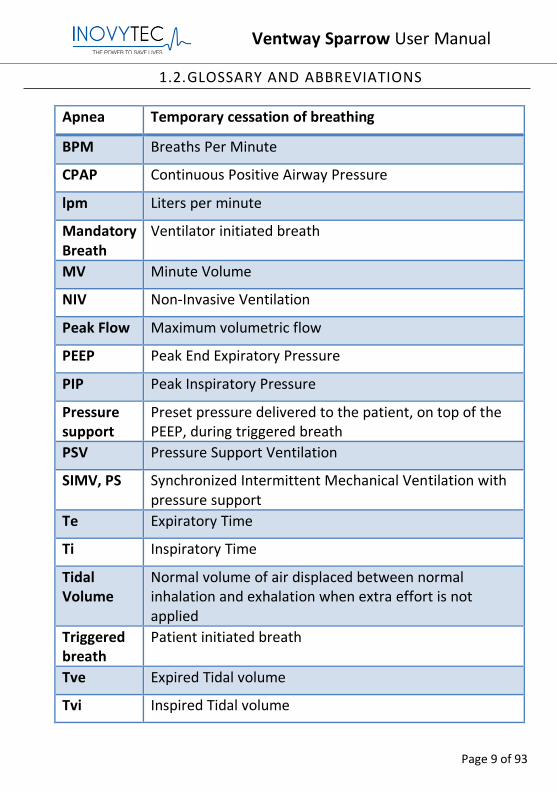
1.2.GLOSSARY AND ABBREVIATIONS
Apnea Temporary cessation of breathing
BPM Breaths Per Minute
CPAP Continuous Positive Airway Pressure
lpm Liters per minute
Mandatory Breath
Ventilator initiated breath
MV Minute Volume
NIV Non-Invasive Ventilation
Peak Flow Maximum volumetric flow
PEEP Peak End Expiratory Pressure
PIP Peak Inspiratory Pressure
Pressure support
Preset pressure delivered to the patient, on top of the PEEP, during triggered breath
PSV Pressure Support Ventilation
SIMV, PS Synchronized Intermittent Mechanical Ventilation with pressure support
Te Expiratory Time
Ti Inspiratory Time
Tidal Volume
Normal volume of air displaced between normal inhalation and exhalation when extra effort is not applied
Triggered breath
Patient initiated breath
Tve Expired Tidal volume
Tvi Inspired Tidal volume
Ventway Sparrow User Manual
Page 10 of 93
2. OVERVIEW OF SYSTEM
2.1. DESCRIPTION OF DEVICE
The Ventway is an emergency portable ventilator, used for transport, EMS
and military applications.
The situations for which it is intended are characterized by attendance of
first responders with limited triage capabilities, requiring a simple yet highly
effective ventilator, that is self-sufficient and lightweight.
The ventilator is suitable for noninvasive ventilation for a full non-vented
ventilation face mask.
Note: The power supply needs to be firmly and statically secured in any EMS environment in which the ventilator is used.
Ventway Sparrow User Manual
Page 11 of 93
3. CONDITIONS FOR USE
INTENDED USE
The Ventway Sparrow ventilator supports adult and pediatric patients
weighing at least 5 kg (11 lb.) in patient transport, and emergency response
with invasive or noninvasive ventilation presets. These settings can be easily
refined using the single rotator/push button and easy read display.
3.1. INDICATIONS FOR USE
The Ventway sparrow ventilator is intended to provide continuous or
intermittent ventilatory support for the care of individuals who require
mechanical ventilation. The ventilator is a restricted medical device intended
for use by qualified, trained personnel under the direction of a physician.
Specifically, the ventilator is applicable for adult and pediatric patients
weighing at least 5 kg, who require the following types of ventilatory
support:
• SIMV Volume Control (VC) with pressure support (PS). The ventilator is
suitable for use in institutional or transport settings.
• CPAP – Continuous Positive Airway Pressure Ventilation with pressure
support, delivered invasively (via endotracheal tube or tracheostomy tube)
or non-invasively (via nasal/full face mask).
Ventway Sparrow User Manual
Page 12 of 93
3.2. CONTRAINDICATIONS
• Patient instructions regarding performing ventilation or any use of life
support equipment
• Acute Pneumothorax
3.3. LIMITATIONS OF USE
Clinical situations potentially affecting accuracy or performance:
• Controlling the flow in the presence of difficult airways, such as severe
lung blockage and asymmetric air entrance to the lung
• Low compliance of the airways
• Asynchronization between patient and ventilator
• Barotrauma
• Behavior of the ventilator in case of barotrauma, monitoring and alerting
in these cases.
Note: The use of humidification is not recommended.
Ventway Sparrow User Manual
Page 13 of 93
4. SAFETY
4.1. ELECTRICAL SAFETY
The device complies with requirements of IEC/EN 60601-1 for general
requirements for safety of medical electrical equipment:
• Class I Equipment BF type applied part
• Mode of operation: Continuous measurement
• Degree of mobility: Portable
4.2. EMC COMPLIANCE
The unit has Class B compliance.
4.3. SAFETY INSTRUCTIONS
Warnings
Basic safety precautions always should be taken, including all those listed below.
DO NOT USE BEFORE READING THIS USER MANUAL.
DO NOT use this device for any purpose other than specified in this manual without written consent and approval from Inovytec Medical Solutions Ltd.
In case of VENTILATOR failure, the lack of immediate access to appropriate alternative means of ventilation can result in PATIENT death.
US Federal Law restricts the sale of this instrument only by, or on the order of, a physician.
The exhaled volume of the patient can differ from the measured exhaled volume due to leaks around the mask.
The device shall not be used in a hyperbaric chamber.
The device shall not be used with nitric oxide.
The device shall not be used with helium or mixtures with helium.
The device accuracy can be affected by the gas added by use of a nebulizer.
Ventway Sparrow User Manual
Page 14 of 93
Cautions
If the device packaging is not intact, do not use the device.
If the device does not turn on, or is not working correctly, discontinue use. Refer servicing or replacement to qualified service personnel.
Do not disassemble any part of the system components. This system is not user-serviceable.
Do not use the equipment if it is not working properly or if it has suffered any damage, for example, by dropping the equipment or splashing water on it.
If the LCD screen is cracked or damaged, check whether the screen can be used, and if not, do not use the device.
If the power button is damaged or stuck, disconnect the patient from the device and remove the battery.
If the rotator switch does not allow changing parameters, the device cannot be used.
The Patient Circuit is single use only. If it is not removed from a new container, it may have already been used and should not be used.
The Patient Circuit can be used for the same patient up to five days.
Do not use a Patient Circuit that is not the original Patient Circuit of the device.
Confirm that the expiration date, found on the Patient Circuit packaging bag, has not been reached.
The device should be used under medical supervision.
When using external oxygen enrichment, please note the following:
• When using demand valve, it will reach min. 90%.
• When using reservoir bag, it may vary depending on oxygen flow rate.
Ventway Sparrow User Manual
Page 15 of 93
Cautions
It is the user’s responsibility to retain information about the patient (by USB connection), otherwise the information will be lost.
Repairs should be undertaken only by personnel trained or authorized by Inovytec Medical Solutions Ltd. Do not modify this equipment without authorization from Inovytec Medical Solutions Ltd.
The device may not operate correctly if used or stored outside the relevant temperature or humidity ranges, as described in the performance specifications.
Strictly follow the warning instructions in this manual.
This instrument is fragile. To prevent damage please handle with care, including while packing and unpacking.
Ensure that the system is only used by a trained person familiar with all system operating procedures. EMS personnel should complete a training program before operating the Ventway Sparrow.
User is prohibited from changing, adding, removing or disassembling any system parts. Warranty shall not apply to any defects, failure or damage caused by improper use and/or improper or inadequate maintenance and care.
The unit is classified as Class IIb, continuously operated, ordinary equipment with applied part and with signal input/ output parts. The device is not intended for use in the presence of flammable substances.
To avoid damage to the screen, do not expose the instrument to direct sunlight for prolonged periods.
The system is approved for IP45 in operation mode with oxygen enrichment. To prevent damage to the instrument or patient cable, avoid liquid spillage while cleaning.
Ventway Sparrow User Manual
Page 16 of 93
Cautions
It is strongly recommended that all Ventway Sparrow parts be replaced with parts purchased from Inovytec Medical Solutions Ltd. or an authorized distributor. Use of other parts may damage the unit and void the warranty.
The ventilator is suitable for noninvasive ventilation for full non-vented ventilation face mask.
During NIV (Non-Invasive Ventilation) the user must use a capnograph in order to monitor CO2 level of the patient.
Covering the ventilator is prohibited.
Ensure that no Latex or natural rubber parts are in patient pathways.
When adding medication to the gas flowing into the patient by using an MDI or nebulizer, please position between mask/ETT and exhalation valve.
Do not obstruct the gas intake ports.
Discarded used or unused patient circuit is classified as clinical waste. As such, the user is responsible for complying with all local and national regulations regarding discarding of clinical waste.
Notes
Dispose of this device and used sensors in accordance with local regulations.
Use the equipment only for the purpose described in these instructions for use.
The contents of this manual are subject to change without prior notice.
The user or any technical personnel who are not formally authorized by Inovytec Medical Solutions Ltd. should not open the device under any circumstances. Opening the device could damage the unit and will void the warranty provided by Inovytec Medical Solutions Ltd.
Ventway Sparrow User Manual
Page 17 of 93
5. SYSTEM COMPONENTS
5.1. UNPACKING THE DEVICE
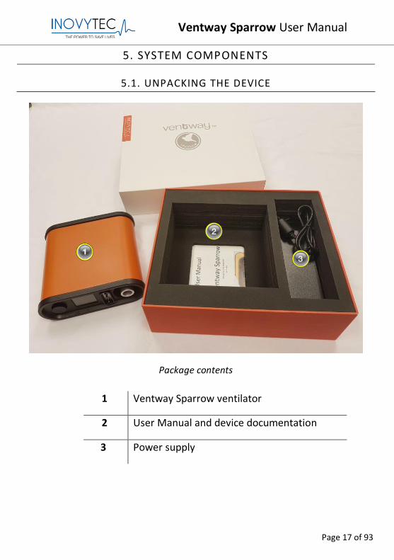
Package contents
1 Ventway Sparrow ventilator
2 User Manual and device documentation
3 Power supply
Ventway Sparrow User Manual
Page 18 of 93
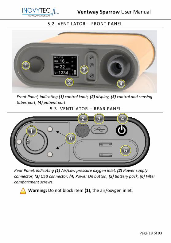
5.2. VENTILATOR – FRONT PANEL
5.3. VENTILATOR – REAR PANEL
Warning: Do not block item (1), the air/oxygen inlet.
Rear Panel, indicating (1) Air/Low pressure oxygen inlet, (2) Power supply
connector, (3) USB connector, (4) Power On button, (5) Battery pack, (6) Filter
compartment screws
Front Panel, indicating (1) control knob, (2) display, (3) control and sensing
tubes port, (4) patient port
Ventway Sparrow User Manual
Page 19 of 93
5.4. VENTILATOR – USE CONFIGURATION
During transport, the ventilator shall be placed in a horizontal position.
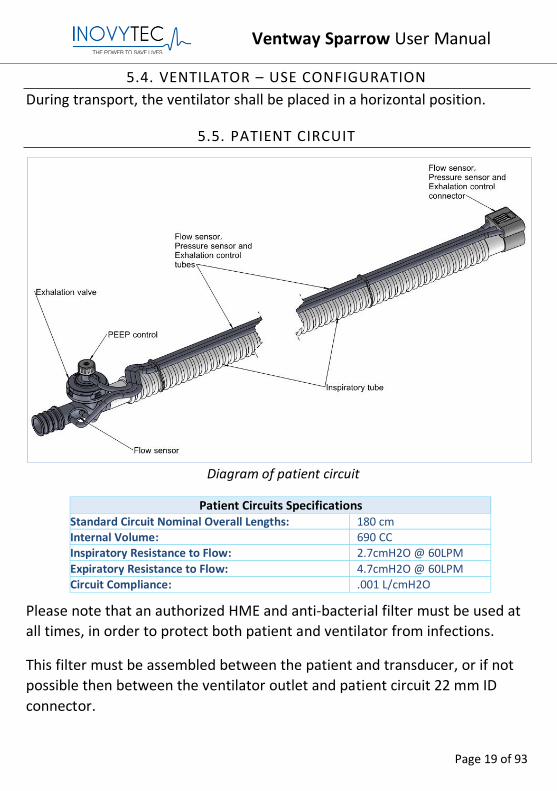
5.5. PATIENT CIRCUIT
Diagram of patient circuit
Patient Circuits Specifications Standard Circuit Nominal Overall Lengths: 180 cm Internal Volume: 690 CC Inspiratory Resistance to Flow: 2.7cmH2O @ 60LPM Expiratory Resistance to Flow: 4.7cmH2O @ 60LPM Circuit Compliance: .001 L/cmH2O
Please note that an authorized HME and anti-bacterial filter must be used at
all times, in order to protect both patient and ventilator from infections.
This filter must be assembled between the patient and transducer, or if not
possible then between the ventilator outlet and patient circuit 22 mm ID
connector.
Ventway Sparrow User Manual
Page 20 of 93
Warning: All parts of the patient circuit are single-use only and
must be discarded after use.
Warning: Antistatic or electrically conductive hoses or tubing are
not to be used in the ventilator breathing system.
Ventway Sparrow User Manual
Page 21 of 93
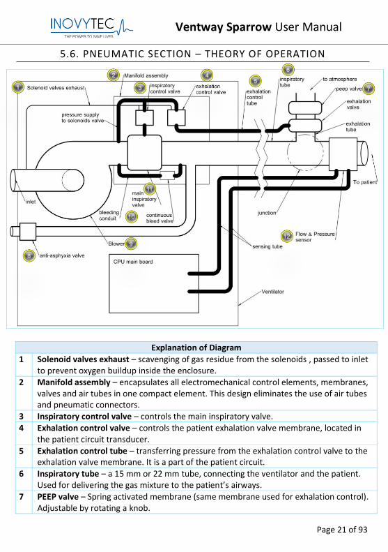
5.6. PNEUMATIC SECTION – THEORY OF OPERATION
Explanation of Diagram
1 Solenoid valves exhaust – scavenging of gas residue from the solenoids , passed to inlet to prevent oxygen buildup inside the enclosure.
2 Manifold assembly – encapsulates all electromechanical control elements, membranes, valves and air tubes in one compact element. This design eliminates the use of air tubes and pneumatic connectors.
3 Inspiratory control valve – controls the main inspiratory valve. 4 Exhalation control valve – controls the patient exhalation valve membrane, located in
the patient circuit transducer. 5 Exhalation control tube – transferring pressure from the exhalation control valve to the
exhalation valve membrane. It is a part of the patient circuit.
6 Inspiratory tube – a 15 mm or 22 mm tube, connecting the ventilator and the patient. Used for delivering the gas mixture to the patient’s airways.
7 PEEP valve – Spring activated membrane (same membrane used for exhalation control). Adjustable by rotating a knob.
Ventway Sparrow User Manual
Page 22 of 93
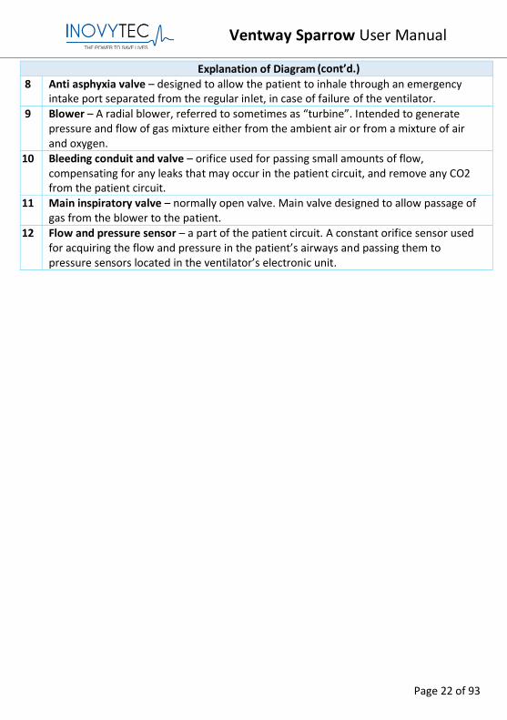
Explanation of Diagram 8 Anti asphyxia valve – designed to allow the patient to inhale through an emergency
intake port separated from the regular inlet, in case of failure of the ventilator.
9 Blower – A radial blower, referred to sometimes as “turbine”. Intended to generate pressure and flow of gas mixture either from the ambient air or from a mixture of air and oxygen.
10 Bleeding conduit and valve – orifice used for passing small amounts of flow, compensating for any leaks that may occur in the patient circuit, and remove any CO2 from the patient circuit.
11 Main inspiratory valve – normally open valve. Main valve designed to allow passage of gas from the blower to the patient.
12 Flow and pressure sensor – a part of the patient circuit. A constant orifice sensor used for acquiring the flow and pressure in the patient’s airways and passing them to pressure sensors located in the ventilator’s electronic unit.
(cont’d.)
Ventway Sparrow User Manual
Page 23 of 93
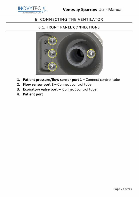
6. CONNECTING THE VENTILATOR
6.1. FRONT PANEL CONNECTIONS
1. Patient pressure/flow sensor port 1 – Connect control tube 2. Flow sensor port 2 – Connect control tube 3. Expiratory valve port – Connect control tube 4. Patient port
Ventway Sparrow User Manual
Page 24 of 93
6.2. REAR PANEL CONNECTIONS
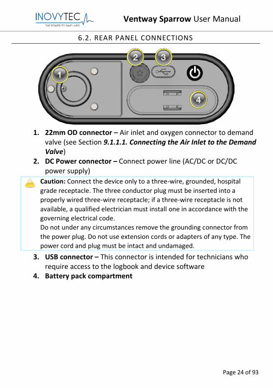
1. 22mm OD connector – Air inlet and oxygen connector to demand
valve (see Section 9.1.1.1. Connecting the Air Inlet to the Demand Valve)
2. DC Power connector – Connect power line (AC/DC or DC/DC power supply)
Caution: Connect the device only to a three-wire, grounded, hospital
grade receptacle. The three conductor plug must be inserted into a
properly wired three-wire receptacle; if a three-wire receptacle is not
available, a qualified electrician must install one in accordance with the
governing electrical code.
Do not under any circumstances remove the grounding connector from
the power plug. Do not use extension cords or adapters of any type. The
power cord and plug must be intact and undamaged.
3. USB connector – This connector is intended for technicians who require access to the logbook and device software
4. Battery pack compartment
Ventway Sparrow User Manual
Page 25 of 93
7. OPERATING THE VENTILATOR
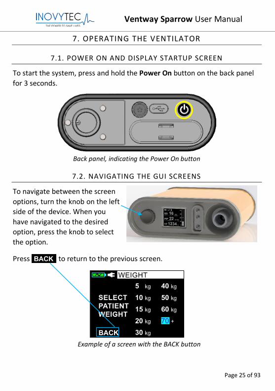
7.1. POWER ON AND DISPLAY STARTUP SCREEN
To start the system, press and hold the Power On button on the back panel
for 3 seconds.
Back panel, indicating the Power On button
7.2. NAVIGATING THE GUI SCREENS
To navigate between the screen
options, turn the knob on the left
side of the device. When you
have navigated to the desired
option, press the knob to select
the option.
Press to return to the previous screen.
Example of a screen with the BACK button
Ventway Sparrow User Manual
Page 26 of 93
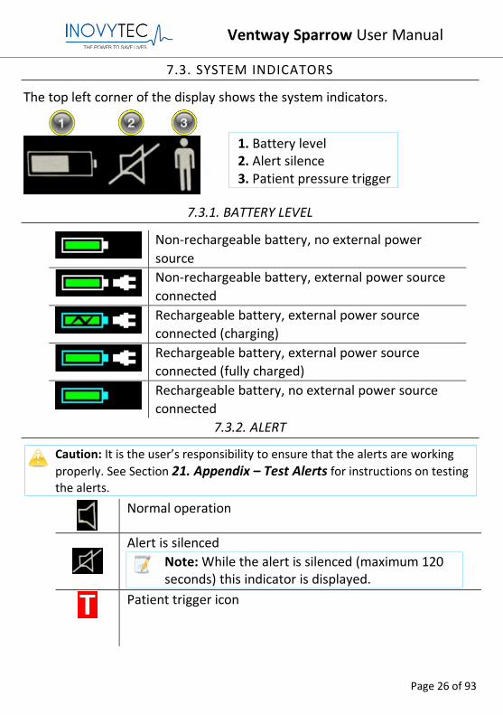
7.3. SYSTEM INDICATORS
The top left corner of the display shows the system indicators.
7.3.1. BATTERY LEVEL
Non-rechargeable battery, no external power
source
Non-rechargeable battery, external power source
connected
Rechargeable battery, external power source
connected (charging)
Rechargeable battery, external power source
connected (fully charged)
Rechargeable battery, no external power source
connected
7.3.2. ALERT
Caution: It is the user’s responsibility to ensure that the alerts are working
properly. See Section 21. Appendix – Test Alerts for instructions on testing the alerts.
Normal operation
Alert is silenced
Note: While the alert is silenced (maximum 120 seconds) this indicator is displayed.
Patient trigger icon
1. Battery level 2. Alert silence 3. Patient pressure trigger
Ventway Sparrow User Manual
Page 27 of 93
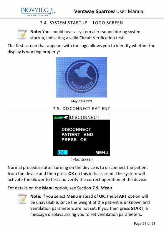
7.4. SYSTEM STARTUP – LOGO SCREEN
Note: You should hear a system alert sound during system
startup, indicating a valid Circuit Verification test.
The first screen that appears with the logo allows you to identify whether the
display is working properly:
Logo screen
7.5. DISCONNECT PATIENT
Initial screen
Normal procedure after turning on the device is to disconnect the patient
from the device and then press OK on this initial screen. The system will
activate the blower to test and verify the correct operation of the device.
For details on the Menu option, see Section 7.9. Menu.
Note: If you select Menu instead of OK, the START option will
be unavailable, since the weight of the patient is unknown and
ventilation parameters are not set. If you then press START, a
message displays asking you to set ventilation parameters.
Ventway Sparrow User Manual
Page 28 of 93
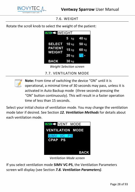
7.6. WEIGHT
Rotate the scroll knob to select the weight of the patient:
Weight Selection screen
7.7. VENTILATION MODE
Note: From time of switching the device “ON” until it is
operational, a minimal time of 30 seconds may pass, unless it is
activated in Auto Backup mode (three seconds pressing the
“ON” button continuously). This will result in a faster operation
time of less than 15 seconds.
Select your initial choice of ventilation mode. You may change the ventilation
mode later if desired. See Section 12. Ventilation Methods for details about
each ventilation mode.
Ventilation Mode screen
If you select ventilation mode SIMV VC-PS, the Ventilation Parameters
screen will display (see Section 7.8. Ventilation Parameters).
Ventway Sparrow User Manual
Page 29 of 93
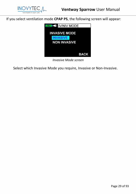
If you select ventilation mode CPAP PS, the following screen will appear:
Invasive Mode screen
Select which Invasive Mode you require, Invasive or Non-Invasive.
Ventway Sparrow User Manual
Page 30 of 93
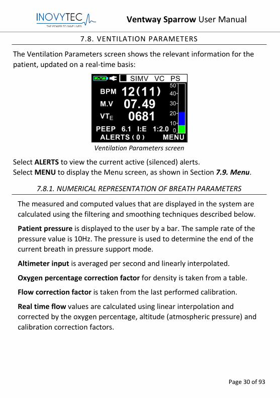
7.8. VENTILATION PARAMETERS
The Ventilation Parameters screen shows the relevant information for the
patient, updated on a real-time basis:
Ventilation Parameters screen
Select ALERTS to view the current active (silenced) alerts.
Select MENU to display the Menu screen, as shown in Section 7.9. Menu.
7.8.1. NUMERICAL REPRESENTATION OF BREATH PARAMETERS
The measured and computed values that are displayed in the system are
calculated using the filtering and smoothing techniques described below.
Patient pressure is displayed to the user by a bar. The sample rate of the
pressure value is 10Hz. The pressure is used to determine the end of the
current breath in pressure support mode.
Altimeter input is averaged per second and linearly interpolated.
Oxygen percentage correction factor for density is taken from a table.
Flow correction factor is taken from the last performed calibration.
Real time flow values are calculated using linear interpolation and
corrected by the oxygen percentage, altitude (atmospheric pressure) and
calibration correction factors.
Ventway Sparrow User Manual
Page 31 of 93
Inspiratory and expiratory tidal volumes are calculated by integrating the
positive and negative flows over time. The negative minute volume is
displayed to the user and the value is used for blower speed corrections.
The positive minute volume is used to determine timing of the current
breath termination.
Please note that due to possible leaks when using non-invasive ventilation,
VTe and VTi may vary substantially.
BPM is calculated as one minute divided by the latest breath length.
Minute volume is calculated as the latest BPM multiplied by the latest
expiratory tidal volume.
I:E is displayed to the user and is calculated per every breath as the
inspiration time divided by the expiration time.
The latest PEEP is displayed to the user, and is updated every breath, as the
minimum pressure measured during that breath.
PIP is displayed to the user by a bar graph. It is the maximum pressure
measured during that breath.
Ventway Sparrow User Manual
Page 32 of 93
7.9. MENU
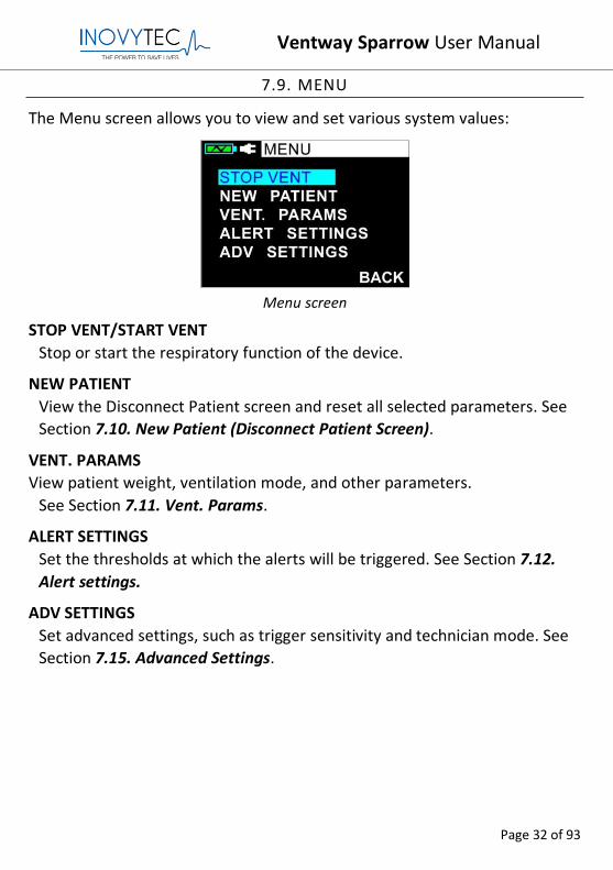
The Menu screen allows you to view and set various system values:
Menu screen
STOP VENT/START VENT
Stop or start the respiratory function of the device.
NEW PATIENT
View the Disconnect Patient screen and reset all selected parameters. See
Section 7.10. New Patient (Disconnect Patient Screen).
VENT. PARAMS
View patient weight, ventilation mode, and other parameters.
See Section 7.11. Vent. Params.
ALERT SETTINGS
Set the thresholds at which the alerts will be triggered. See Section 7.12.
Alert settings.
ADV SETTINGS
Set advanced settings, such as trigger sensitivity and technician mode. See
Section 7.15. Advanced Settings.
Ventway Sparrow User Manual
Page 33 of 93
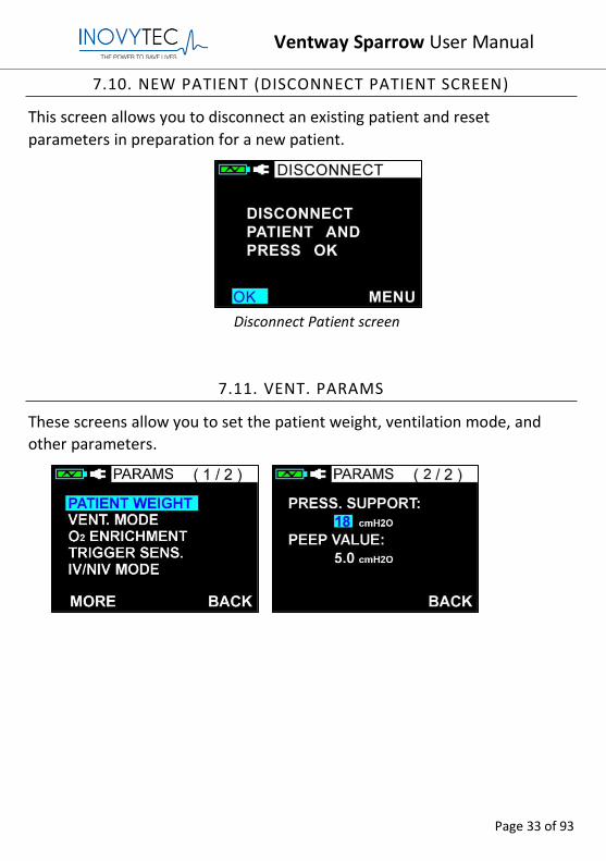
7.10. NEW PATIENT (DISCONNECT PATIENT SCREEN)
This screen allows you to disconnect an existing patient and reset
parameters in preparation for a new patient.
Disconnect Patient screen
7.11. VENT. PARAMS
These screens allow you to set the patient weight, ventilation mode, and
other parameters.
Ventway Sparrow User Manual
Page 34 of 93
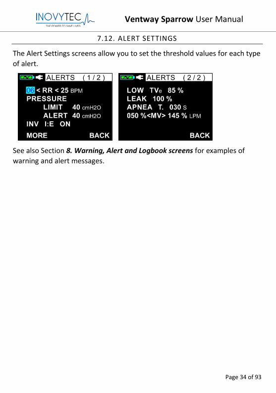
7.12. ALERT SETTINGS
The Alert Settings screens allow you to set the threshold values for each type
of alert.
See also Section 8. Warning, Alert and Logbook screens for examples of
warning and alert messages.
Ventway Sparrow User Manual
Page 35 of 93
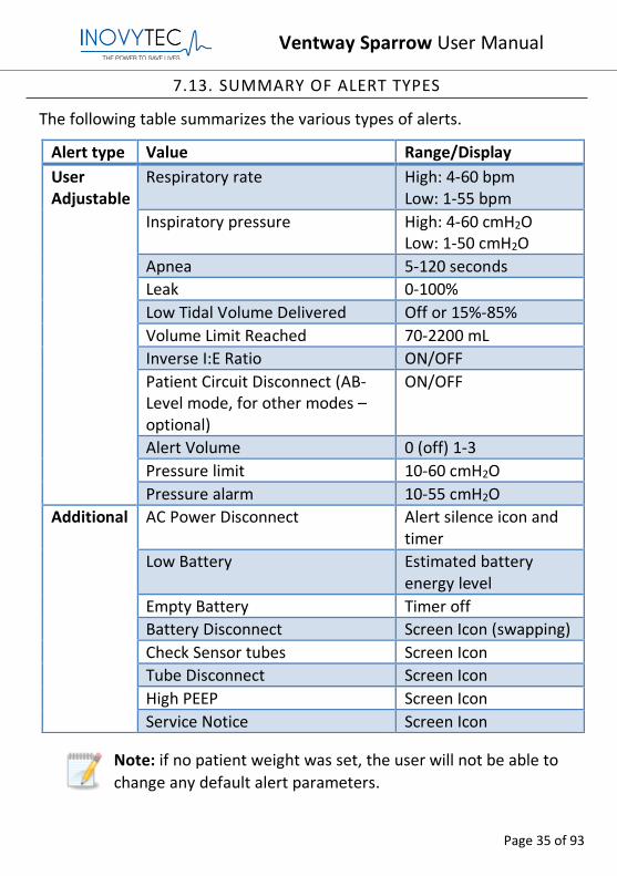
7.13. SUMMARY OF ALERT TYPES
The following table summarizes the various types of alerts.
Note: if no patient weight was set, the user will not be able to
change any default alert parameters.
Alert type Value Range/Display
User Adjustable
Respiratory rate High: 4-60 bpm Low: 1-55 bpm
Inspiratory pressure High: 4-60 cmH2O Low: 1-50 cmH2O
Apnea 5-120 seconds
Leak 0-100%
Low Tidal Volume Delivered Off or 15%-85%
Volume Limit Reached 70-2200 mL
Inverse I:E Ratio ON/OFF
Patient Circuit Disconnect (AB-Level mode, for other modes – optional)
ON/OFF
Alert Volume 0 (off) 1-3
Pressure limit 10-60 cmH2O
Pressure alarm 10-55 cmH2O
Additional AC Power Disconnect Alert silence icon and timer
Low Battery Estimated battery energy level
Empty Battery Timer off
Battery Disconnect Screen Icon (swapping)
Check Sensor tubes Screen Icon
Tube Disconnect Screen Icon
High PEEP Screen Icon
Service Notice Screen Icon
Ventway Sparrow User Manual
Page 36 of 93
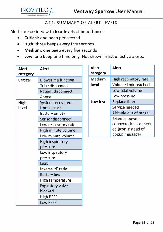
7.14. SUMMARY OF ALERT LEVELS
Alerts are defined with four levels of importance:
• Critical: one beep per second
• High: three beeps every five seconds
• Medium: one beep every five seconds
• Low: one beep one time only. Not shown in list of active alerts.
Alert category
Alert
Critical
Blower malfunction
Tube disconnect
Patient disconnect
Apnea
High level
System recovered from a crash
Battery empty
Sensor disconnect
Low respiratory rate
High minute volume
Low minute volume
High inspiratory pressure
Low inspiratory pressure
Leak
Inverse I:E ratio
Battery low
High temperature
Expiratory valve blocked
High PEEP
Low PEEP
Alert category
Alert
Medium level
High respiratory rate
Volume limit reached
Low tidal volume
Low pressure
Low level Replace filter
Service needed
Altitude out of range
External power connected/disconnected (icon instead of popup message)
Ventway Sparrow User Manual
Page 37 of 93
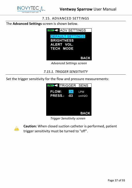
7.15. ADVANCED SETTINGS
The Advanced Settings screen is shown below.
Advanced Settings screen
7.15.1. TRIGGER SENSITIVITY
Set the trigger sensitivity for the flow and pressure measurements:
Trigger Sensitivity screen
Caution: When closed suction catheter is performed, patient
trigger sensitivity must be turned to "off".
Ventway Sparrow User Manual
Page 38 of 93
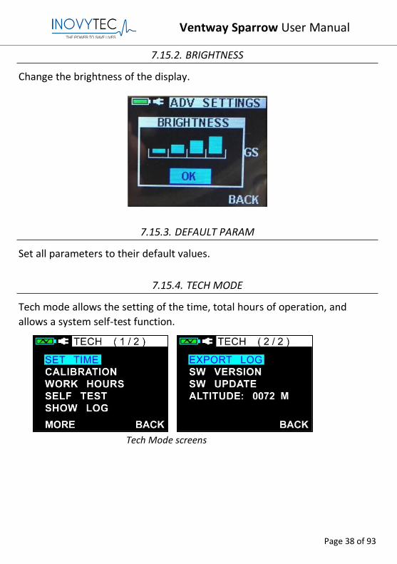
7.15.2. BRIGHTNESS
Change the brightness of the display.
7.15.3. DEFAULT PARAM
Set all parameters to their default values.
7.15.4. TECH MODE
Tech mode allows the setting of the time, total hours of operation, and
allows a system self-test function.
Tech Mode screens
Ventway Sparrow User Manual
Page 39 of 93
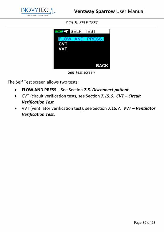
7.15.5. SELF TEST
Self Test screen
The Self Test screen allows two tests:
• FLOW AND PRESS – See Section 7.5. Disconnect patient
• CVT (circuit verification test), see Section 7.15.6. CVT – Circuit
Verification Test
• VVT (ventilator verification test), see Section 7.15.7. VVT – Ventilator
Verification Test.
Ventway Sparrow User Manual
Page 40 of 93
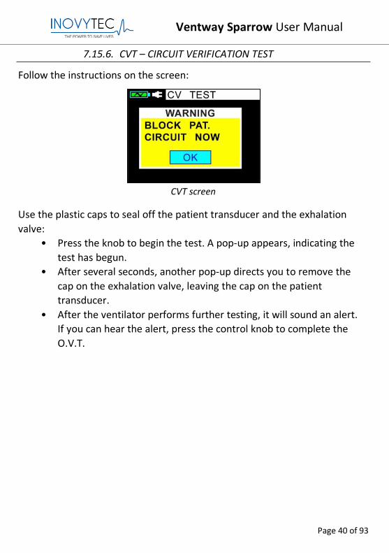
7.15.6. CVT – CIRCUIT VERIFICATION TEST
Follow the instructions on the screen:
CVT screen
Use the plastic caps to seal off the patient transducer and the exhalation
valve:
• Press the knob to begin the test. A pop-up appears, indicating the
test has begun.
• After several seconds, another pop-up directs you to remove the
cap on the exhalation valve, leaving the cap on the patient
transducer.
• After the ventilator performs further testing, it will sound an alert.
If you can hear the alert, press the control knob to complete the
O.V.T.
Ventway Sparrow User Manual
Page 41 of 93
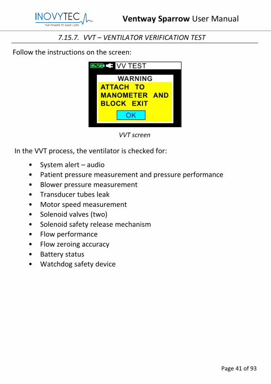
7.15.7. VVT – VENTILATOR VERIFICATION TEST
Follow the instructions on the screen:
VVT screen
In the VVT process, the ventilator is checked for:
• System alert – audio
• Patient pressure measurement and pressure performance
• Blower pressure measurement
• Transducer tubes leak
• Motor speed measurement
• Solenoid valves (two)
• Solenoid safety release mechanism
• Flow performance
• Flow zeroing accuracy
• Battery status
• Watchdog safety device
Ventway Sparrow User Manual
Page 42 of 93
8. WARNING, ALERT AND LOGBOOK SCREENS
This section provides examples of typical system messages.
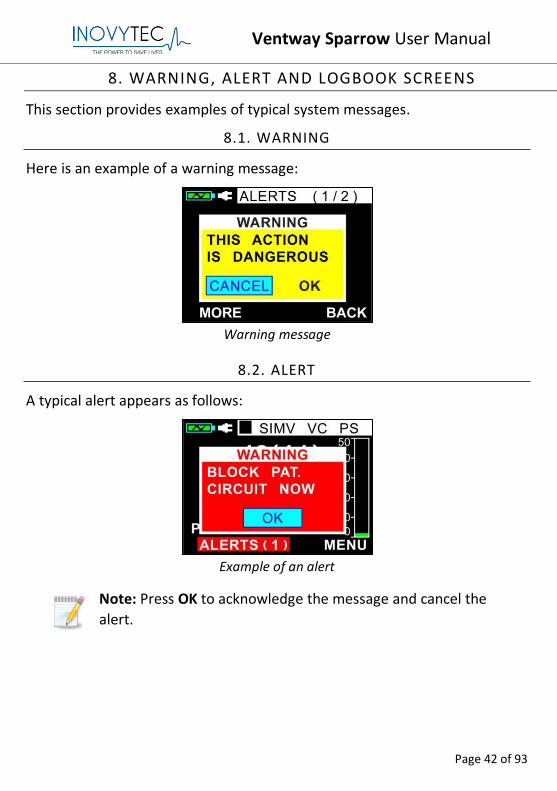
8.1. WARNING
Here is an example of a warning message:
Warning message
8.2. ALERT
A typical alert appears as follows:
Example of an alert
Note: Press OK to acknowledge the message and cancel the
alert.
Ventway Sparrow User Manual
Page 43 of 93
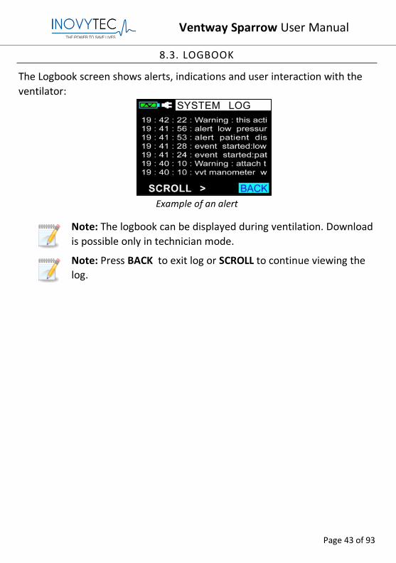
8.3. LOGBOOK
The Logbook screen shows alerts, indications and user interaction with the
ventilator:
Example of an alert
Note: The logbook can be displayed during ventilation. Download
is possible only in technician mode.
Note: Press BACK to exit log or SCROLL to continue viewing the
log.
Ventway Sparrow User Manual
Page 44 of 93
9. DEFAULT PARAMETERS
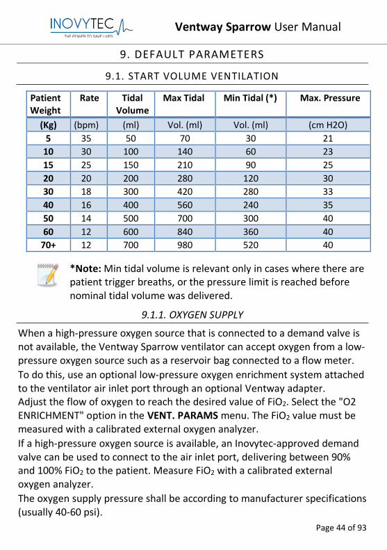
9.1. START VOLUME VENTILATION
Patient Weight
Rate Tidal Volume
Max Tidal Min Tidal (*) Max. Pressure
(Kg) (bpm) (ml) Vol. (ml) Vol. (ml) (cm H2O)
5 35 50 70 30 21
10 30 100 140 60 23
15 25 150 210 90 25
20 20 200 280 120 30
30 18 300 420 280 33
40 16 400 560 240 35
50 14 500 700 300 40
60 12 600 840 360 40
70+ 12 700 980 520 40
*Note: Min tidal volume is relevant only in cases where there are patient trigger breaths, or the pressure limit is reached before nominal tidal volume was delivered.
9.1.1. OXYGEN SUPPLY
When a high-pressure oxygen source that is connected to a demand valve is not available, the Ventway Sparrow ventilator can accept oxygen from a low-pressure oxygen source such as a reservoir bag connected to a flow meter.
To do this, use an optional low-pressure oxygen enrichment system attached to the ventilator air inlet port through an optional Ventway adapter. Adjust the flow of oxygen to reach the desired value of FiO2. Select the "O2 ENRICHMENT" option in the VENT. PARAMS menu. The FiO2 value must be measured with a calibrated external oxygen analyzer.
If a high-pressure oxygen source is available, an Inovytec-approved demand valve can be used to connect to the air inlet port, delivering between 90% and 100% FiO2 to the patient. Measure FiO2 with a calibrated external oxygen analyzer.
The oxygen supply pressure shall be according to manufacturer specifications (usually 40-60 psi).
Ventway Sparrow User Manual
Page 45 of 93
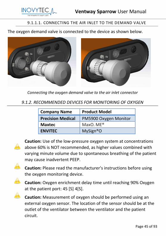
9.1.1.1. CONNECTING THE AIR INLET TO THE DEMAND VALVE
The oxygen demand valve is connected to the device as shown below.
Connecting the oxygen demand valve to the air inlet connector
9.1.2. RECOMMENDED DEVICES FOR MONITORING OF OXYGEN
Company Name Product Model
Precision Medical PM5900 Oxygen Monitor
Maxtec MaxO2 ME®
ENVITEC MySign®O
Caution: Use of the low-pressure oxygen system at concentrations
above 60% is NOT recommended, as higher values combined with
varying minute volume due to spontaneous breathing of the patient
may cause inadvertent PEEP.
Caution: Please read the manufacturer's instructions before using
the oxygen monitoring device.
Caution: Oxygen enrichment delay time until reaching 90% Oxygen
at the patient port: 45 [S] 4[S].
Caution: Measurement of oxygen should be performed using an
external oxygen sensor. The location of the sensor should be at the
outlet of the ventilator between the ventilator and the patient
circuit.
Ventway Sparrow User Manual
Page 46 of 93
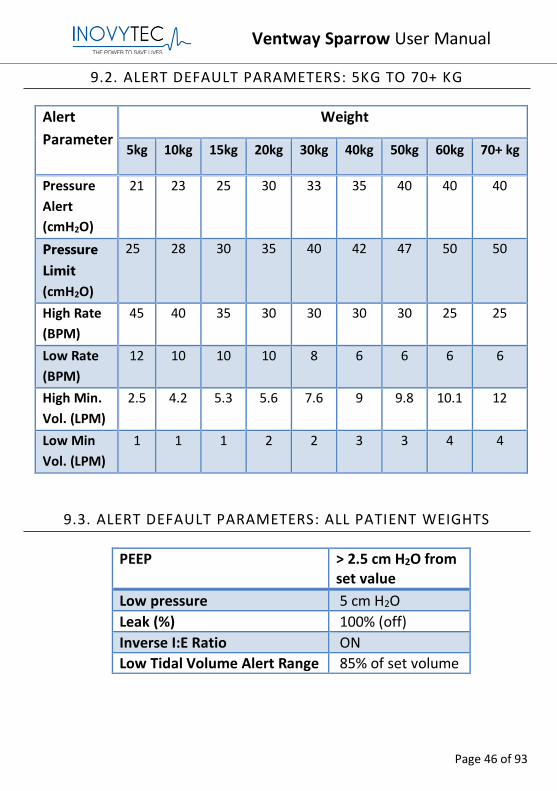
9.2. ALERT DEFAULT PARAMETERS: 5KG TO 70+ KG
Alert
Parameter
Weight
5kg 10kg 15kg 20kg 30kg 40kg 50kg 60kg 70+ kg
Pressure
Alert
(cmH2O)
21 23 25 30 33 35 40 40 40
Pressure
Limit
(cmH2O)
25 28 30 35 40 42 47 50 50
High Rate
(BPM)
45 40 35 30 30 30 30 25 25
Low Rate
(BPM)
12 10 10 10 8 6 6 6 6
High Min.
Vol. (LPM)
2.5 4.2 5.3 5.6 7.6 9 9.8 10.1 12
Low Min
Vol. (LPM)
1 1 1 2 2 3 3 4 4
9.3. ALERT DEFAULT PARAMETERS: ALL PATIENT WEIGHTS
PEEP > 2.5 cm H2O from set value
Low pressure 5 cm H2O
Leak (%) 100% (off)
Inverse I:E Ratio ON
Low Tidal Volume Alert Range 85% of set volume
Ventway Sparrow User Manual
Page 47 of 93
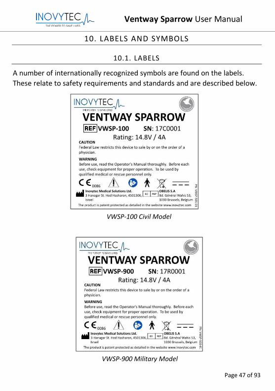
10. LABELS AND SYMBOLS
10.1. LABELS
A number of internationally recognized symbols are found on the labels.
These relate to safety requirements and standards and are described below.
VWSP-100 Civil Model
VWSP-900 Military Model
Ventway Sparrow User Manual
Page 48 of 93
10.2. SYMBOLS
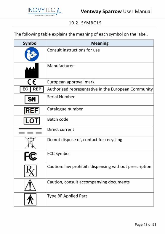
The following table explains the meaning of each symbol on the label.
Symbol Meaning
Consult instructions for use
Manufacturer
European approval mark
Authorized representative in the European Community
Serial Number
Catalogue number
Batch code
Direct current
Do not dispose of, contact for recycling
FCC Symbol
Caution: law prohibits dispensing without prescription
Caution, consult accompanying documents
Type BF Applied Part
Ventway Sparrow User Manual
Page 49 of 93
11. CLEANING AND DISINFECTING
Caution: The system is approved for IP45 in operation mode with oxygen enrichment. To avoid damage to the instrument or patient cable, be careful of liquid spillage while cleaning.
Caution: Do not expose the instrument, patient cable or sensors to sprays, or any other type of solvents.
Caution: Be sure to turn the power off and disconnect the AC power cord from the power source before performing cleaning procedures.
This instrument requires routine cleaning, which includes removal of any soil or dirt from the external surfaces. A soft cloth dampened lightly with water may be used.
To disinfect the ventilator, clean with 70% medical grade alcohol using a dampened soft towel or wipe for two minutes.
Ventway Sparrow User Manual
Page 50 of 93
12. VENTILATION METHODS
12.1. SIMV-VC (PS)FLOW CHART
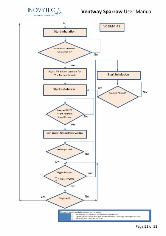
In VC-SIMV, the patient is supplied with the set tidal volume VT during the mandatory breaths. The mandatory breaths are synchronized with the patient’s own breathing attempts. Mandatory breaths are prevented from being applied during spontaneous expiration, by providing that a patient-triggered mandatory breath can only be triggered within a trigger window. If the expiration phase (and with it the spontaneous breathing time) is shortened on account of synchronization, the next expiration phase will be extended. This adaptation prevents a change in the number of mandatory breaths. If no independent breathing attempt is detected during the trigger window, the machine-triggered mandatory breaths are applied. Thus, the minute volume MV remains constant over time. If the breathing attempts of the patient are insufficient to trigger the mandatory breath, the machine-triggered mandatory breaths are applied. The patient can breathe spontaneously at PEEP level during the expiration phase. During spontaneous breathing at PEEP level, the patient can be pressure-supported using PS.
Please note:
1. The number of breaths is set by the patient weight (more weight = less breaths/minute). BPM=mandatory breaths.
2. It is volume controlled (although pressure is constantly being monitored).
3. Either the machine or patient can trigger the breath. 4. Trigger definition: If the patient reaches -2 cm H2O in less than 300
msec then a trigger breath is initiated. 5. Trigger activation window: 300 msec after termination of breath until
initiation of new breath If no independent breathing attempt is detected during the trigger window, the machine-triggered mandatory breath is applied.
Ventway Sparrow User Manual
Page 51 of 93
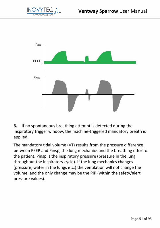
6. If no spontaneous breathing attempt is detected during the inspiratory trigger window, the machine-triggered mandatory breath is applied.
The mandatory tidal volume (VT) results from the pressure difference between PEEP and Pinsp, the lung mechanics and the breathing effort of the patient. Pinsp is the inspiratory pressure (pressure in the lung throughout the inspiratory cycle). If the lung mechanics changes (pressure, water in the lungs etc.) the ventilation will not change the volume, and the only change may be the PIP (within the safety/alert pressure values).
Ventway Sparrow User Manual
Page 52 of 93
Ventway Sparrow User Manual
Page 53 of 93
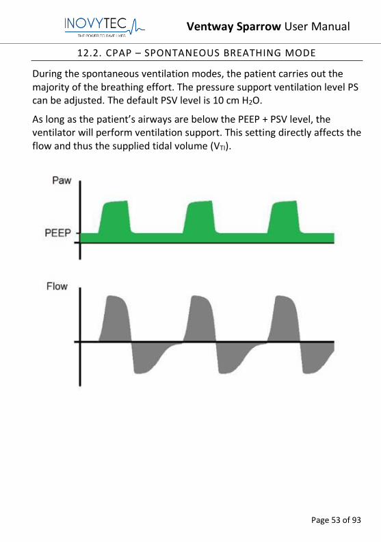
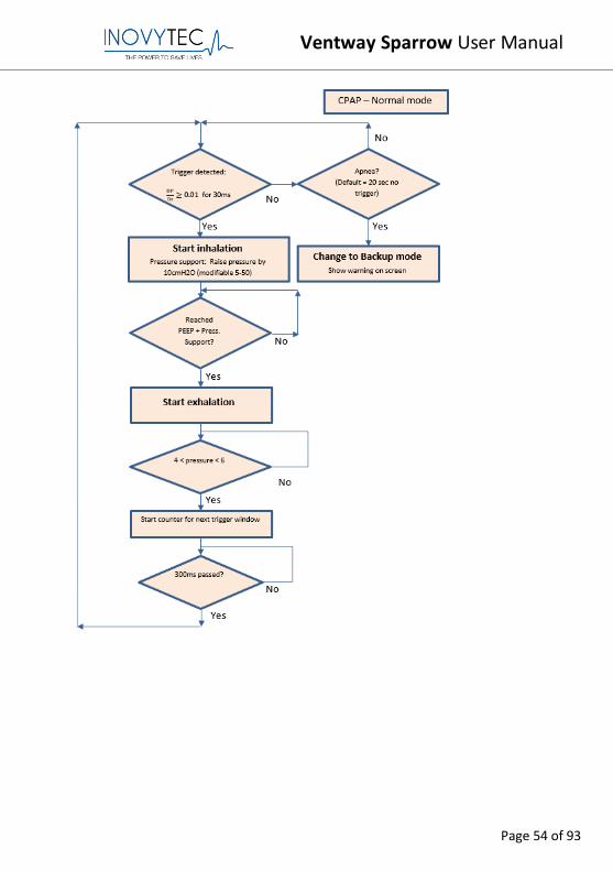
12.2. CPAP – SPONTANEOUS BREATHING MODE
During the spontaneous ventilation modes, the patient carries out the majority of the breathing effort. The pressure support ventilation level PS can be adjusted. The default PSV level is 10 cm H2O.
As long as the patient’s airways are below the PEEP + PSV level, the ventilator will perform ventilation support. This setting directly affects the flow and thus the supplied tidal volume (VTI).
Ventway Sparrow User Manual
Page 54 of 93
Ventway Sparrow User Manual
Page 55 of 93
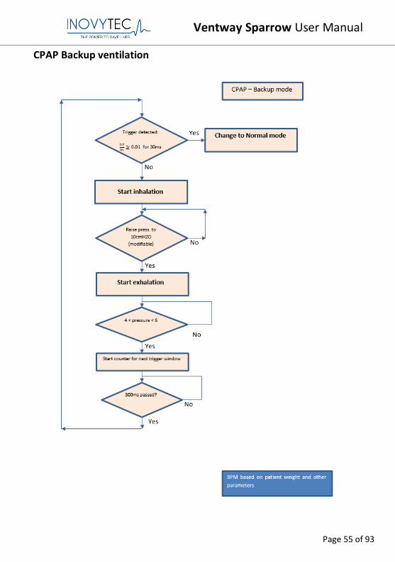
CPAP Backup ventilation
Ventway Sparrow User Manual
Page 56 of 93
12.3. BACKUP VENTILATION MODE
Note: Backup will not occur when the user inserts weight, selects
a ventilation mode and does not press OK. In this situation, a
trigger is received from the patient and the respiration is
performed according to the ventilation mode.
Backup mode is an alternative ventilation method taking place when the ventilator patient circuit is connected to the patient in these situations:
1. Patient is ventilated in CPAP mode and does not initiate any spontaneous breaths for more than 30 seconds.
2. Patient is connected to the ventilator, and for some reason, the user did not start ventilation after connecting the patient.
3. Patient is connected to the ventilator, and user has paused ventilation. In this case when trigger is sensed by the ventilator, the ventilation will automatically resume.
The result of using this backup mode is that the patient will be ventilated in case of losing the ability to initiate spontaneous breaths in CPAP mode, or if an emergency or user error has occurred in the preliminary stages of ventilation setup, or when pausing the ventilator for some reason without resuming ventilation.
1. Backup Ventilation in CPAP
If during CPAP ventilation, the patient stops initiating spontaneous breaths for more than 20 seconds--> Apnea alert appears. If the patient does not initiate a spontaneous breath for an additional 10 seconds (total of 30 seconds), then backup ventilation is initiated:
-Screen displays an alert: "Backup Ventilation Started" and "OK" button for user approval appears. Ventilation will start even if user has not pressed OK. Alert will appear on screen for 10 seconds while audio prompt is activated.
Ventway Sparrow User Manual
Page 57 of 93
• BPM = patient weight based
• Volume, Pressure, MV and all other alerts which are patient weight based remain unchanged.
• Ventilation method is changed to SIMV - VC - PS with the last patient weight parameters dialed in.
• BPM value is patient weight based.
• Resuming to CPAP ventilation will be possible either by patient trigger (will alert on screen: "CPAP ventilation resumed" - "OK"), or user switching back to CPAP or SIMV - VC - PS manually, through the "MENU" option on the main screen.
• All alerts and user inputs will be logged in logbook.
• Every 30 seconds an alert is issued "Backup ventilation active"--"OK".
2. Backup Ventilation before starting patient ventilation If patient is connected to the ventilator, the following conditions may also initiate backup ventilation:
a) Ventilation has not started yet, but ventilator is turned on (either patient weight, ventilation method or start command was not chosen by the user). b) Patient trigger (pressure -2.5 cm H2O or -5 lpm or greater) was sensed.
If conditions a) and b) above were met, then backup ventilation starts.
• "Backup ventilation mode" alert is activated - "OK" appears on screen. User approval does not prevent going into backup mode.
• " Backup ventilation mode" icon appears on top of screen after last alert was either accepted or discarded.
If Patient weight was entered, the device ventilates according to the given weight parameters. If Patient weight was not entered:
1. Initial pressure support value is set to PS=10 cm H2O. 2. Tidal volume is calculated during ventilation. 3. 3 breaths are given to the patient at identical parameters (PS=10
cmH2O) at 10 BPM rate.
Ventway Sparrow User Manual
Page 58 of 93
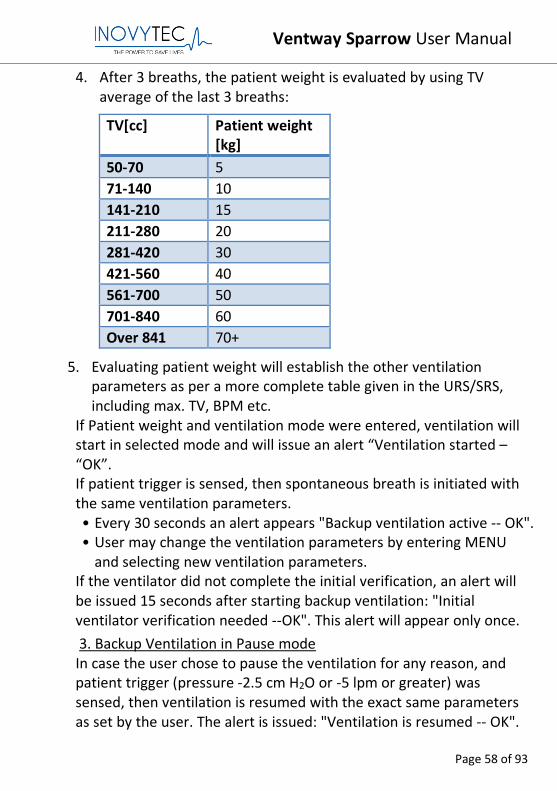
4. After 3 breaths, the patient weight is evaluated by using TV average of the last 3 breaths:
TV[cc] Patient weight [kg]
50-70 5
71-140 10
141-210 15
211-280 20
281-420 30
421-560 40
561-700 50
701-840 60
Over 841 70+
5. Evaluating patient weight will establish the other ventilation parameters as per a more complete table given in the URS/SRS, including max. TV, BPM etc.
If Patient weight and ventilation mode were entered, ventilation will start in selected mode and will issue an alert “Ventilation started – “OK”. If patient trigger is sensed, then spontaneous breath is initiated with the same ventilation parameters. • Every 30 seconds an alert appears "Backup ventilation active -- OK". • User may change the ventilation parameters by entering MENU
and selecting new ventilation parameters. If the ventilator did not complete the initial verification, an alert will be issued 15 seconds after starting backup ventilation: "Initial ventilator verification needed --OK". This alert will appear only once.
3. Backup Ventilation in Pause mode In case the user chose to pause the ventilation for any reason, and patient trigger (pressure -2.5 cm H2O or -5 lpm or greater) was sensed, then ventilation is resumed with the exact same parameters as set by the user. The alert is issued: "Ventilation is resumed -- OK".
Ventway Sparrow User Manual
Page 59 of 93
13. SERVICE AND MAINTENANCE
Note: The user or any technical personnel who are not formally
authorized by Inovytec Medical Solutions Ltd. must not open the
Ventway Sparrow device under any circumstances. Opening the
Ventway Sparrow device may damage the unit and will void the
warranty provided by Inovytec Medical Solutions Ltd.
The system requires maintenance on a routine basis of 15,000 operation
hours or three years (whichever is first). Service should only be provided
by an authorized Inovytec Medical Solutions Ltd. representative.
13.1. DEVICE CALIBRATION AND SOFTWARE UPGRADES
Calibration and upgrade of the software are performed by the factory, or
in technician mode using a password provided by Inovytec.
Ventway Sparrow User Manual
Page 60 of 93
14. TROUBLESHOOTING
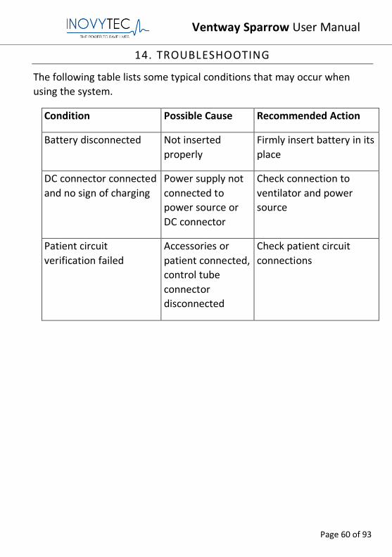
The following table lists some typical conditions that may occur when
using the system.
Condition Possible Cause Recommended Action
Battery disconnected Not inserted
properly
Firmly insert battery in its
place
DC connector connected
and no sign of charging
Power supply not
connected to
power source or
DC connector
Check connection to
ventilator and power
source
Patient circuit
verification failed
Accessories or
patient connected,
control tube
connector
disconnected
Check patient circuit
connections
Ventway Sparrow User Manual
Page 61 of 93
15. SPECIFICATIONS
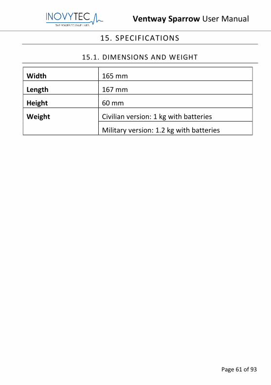
15.1. DIMENSIONS AND WEIGHT
Width 165 mm
Length 167 mm
Height 60 mm
Weight Civilian version: 1 kg with batteries
Military version: 1.2 kg with batteries
Ventway Sparrow User Manual
Page 62 of 93
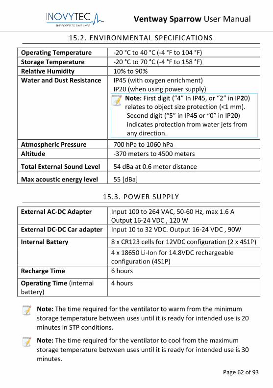
15.2. ENVIRONMENTAL SPECIFICATIONS
Operating Temperature -20 °C to 40 °C (-4 °F to 104 °F)
Storage Temperature -20 °C to 70 °C (-4 °F to 158 °F)
Relative Humidity 10% to 90%
Water and Dust Resistance IP45 (with oxygen enrichment) IP20 (when using power supply)
Note: First digit (“4” In IP45, or “2” in IP20) relates to object size protection (<1 mm). Second digit (“5” in IP45 or “0” in IP20) indicates protection from water jets from any direction.
Atmospheric Pressure 700 hPa to 1060 hPa
Altitude -370 meters to 4500 meters
Total External Sound Level 54 dBa at 0.6 meter distance
Max acoustic energy level 55 [dBa]
15.3. POWER SUPPLY
External AC-DC Adapter Input 100 to 264 VAC, 50-60 Hz, max 1.6 A Output 16-24 VDC , 120 W
External DC-DC Car adapter Input 10 to 32 VDC. Output 16-24 VDC , 90W
Internal Battery 8 x CR123 cells for 12VDC configuration (2 x 4S1P)
4 x 18650 Li-Ion for 14.8VDC rechargeable configuration (4S1P)
Recharge Time 6 hours
Operating Time (internal battery)
4 hours
Note: The time required for the ventilator to warm from the minimum
storage temperature between uses until it is ready for intended use is 20
minutes in STP conditions.
Note: The time required for the ventilator to cool from the maximum
storage temperature between uses until it is ready for intended use is 30
minutes.
Ventway Sparrow User Manual
Page 63 of 93
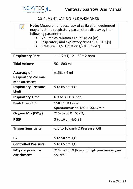
15.4. VENTILATION PERFORMANCE
Note: Measurement accuracy of calibration equipment may affect the respiratory parameters display by the following parameters:
• Volume calculation : +/-2% or 20 [cc] • Inspiratory and expiratory times : +/- 0.02 [s] • Pressure : +/- 0.75% or +/- 0.1 [mbar]
Respiratory Rate 1 – 12 ±1, 12 – 50 ± 2 bpm
Tidal Volume 50-1800 mL
Accuracy of Respiratory Volume Measurement
±15% + 4 ml
Inspiratory Pressure Limit
5 to 65 cmH2O
Inspiratory Time 0.3 to 3 ±10% sec
Peak Flow (PIF) 150 ±10% L/min Spontaneous to 180 ±10% L/min
Oxygen Mix (FiO2 ) 21% to 95% ±5% O2
PEEP 5 to 10 cmH2O ±1,
Trigger Sensitivity
-2.5 to 10 cmH2O Pressure, Off
PS 5 to 50 cmH2O
Controlled Pressure 5 to 65 cmH2O
FiO2 low pressure enrichment
21% to 100% (low and high pressure oxygen source)
Ventway Sparrow User Manual
Page 64 of 93
15.5. STANDARDS AND SAFETY REQUIREMENTS
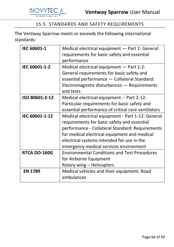
The Ventway Sparrow meets or exceeds the following international standards:
IEC 60601-1 Medical electrical equipment — Part 1: General requirements for basic safety and essential performance
IEC 60601-1-2 Medical electrical equipment — Part 1-2: General requirements for basic safety and essential performance — Collateral Standard: Electromagnetic disturbances — Requirements and tests
ISO 80601-2-12 Medical electrical equipment -- Part 2-12: Particular requirements for basic safety and essential performance of critical care ventilators
IEC 60601-1-12 Medical electrical equipment - Part 1-12: General requirements for basic safety and essential performance - Collateral Standard: Requirements for medical electrical equipment and medical electrical systems intended for use in the emergency medical services environment
RTCA DO-160G Environmental Conditions and Test Procedures for Airborne Equipment Rotary wing – Helicopters
EN 1789 Medical vehicles and their equipment. Road ambulances
Ventway Sparrow User Manual
Page 65 of 93
16. CLEANING AND ROUTINE MAINTENANCE
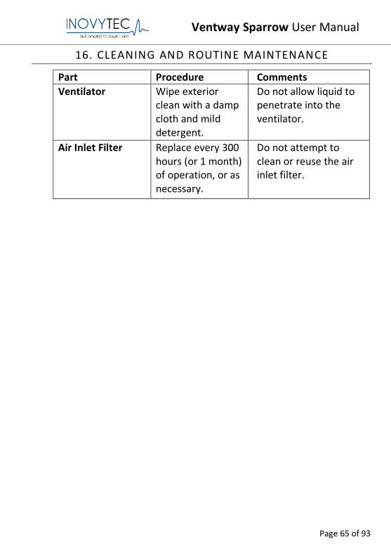
Part Procedure Comments
Ventilator Wipe exterior clean with a damp cloth and mild detergent.
Do not allow liquid to penetrate into the ventilator.
Air Inlet Filter Replace every 300 hours (or 1 month) of operation, or as necessary.
Do not attempt to clean or reuse the air inlet filter.
Ventway Sparrow User Manual
Page 66 of 93
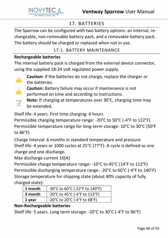
17. BATTERIES
The Sparrow can be configured with two battery options: an internal, re-
chargeable, non-removable battery pack, and a removable battery pack.
The battery should be charged or replaced when not in use.
17.1. BATTERY MAINTENANCE
Rechargeable batteries
The internal battery pack is charged from the external device connector,
using the supplied 18-24 volt regulated power supply.
Caution: If the batteries do not charge, replace the charger or the batteries.
Caution: Battery failure may occur if maintenance is not performed on time and according to instructions.
Note: If charging at temperatures over 30°C, charging time may
be extended.
Shelf life: 4 years. First time charging: 6 hours
Permissible charging temperature range: -20°C to 50°C (-4°F to 122°F)
Permissible temperature range for long-term storage: 10°C to 30°C (50°F
to 86°F)
Charge Interval: 6 months in standard temperature and pressure Shelf life: 4 years or 1000 cycles at 25°C (77°F). A cycle is defined as one
charge and one discharge.
Max discharge current 10[A]
Permissible charge temperature range: -10°C to 45°C (14°F to 113°F)
Permissible discharging temperature range: -20°C to 60°C (-4°F to 140°F)
Storage temperature for shipping state (about 40% capacity of fully
charged state): 1 month -30°C to 60°C (-22°F to 140°F) 3 month -20°C to 45°C (-4°F to 113°F)
1 year -20°C to 20°C (-4°F to 68°F)
Non-Rechargeable batteries
Shelf life: 5 years. Long term storage: -20°C to 30°C (-4°F to 86°F)
Ventway Sparrow User Manual
Page 67 of 93
18. PARTS AND ACCESSORIES
This Section outlines information for ordering and shipment of
replacement parts for the Ventway Sparrow.
All equipment and accessories are available directly from Inovytec
Medical Solutions Ltd. or from an authorized distributor. For a list of
Inovytec Medical Solutions Ltd. distributors please visit our web site at
When ordering parts, specify the serial number of your unit and the part
number of the item(s) you are ordering. A schedule of part numbers may
be found in the Equipment and Accessory Inventory list below.
Forward orders to:
Inovytec Medical Solutions Ltd.
3 Hanagar St., POB 7282,
Hod-Hasharon 4501306, Israel
Tel: +972 9 7794135
E-mail: [email protected]
Web Site: http://www.Inovytec.com
Caution: It is strongly recommended that all Ventway Sparrow
parts be replaced with parts purchased from Inovytec Medical
Solutions Ltd. or an authorized distributor. Use of other parts may
damage the unit and could void the unit warranty.
Note: Dispose of this device and of used sensors in accordance
with local regulations.
Ventway Sparrow User Manual
Page 68 of 93
19. REGULATORY
Manufacturer:
3 Hanagar St., POB 7282,
Hod-Hasharon 4501306, Israel
Tel: +972 9 7794135
E-mail: [email protected]
Web Site: http://www.Inovytec.com
Européen Agent Information:
OBELIS S.A. Bd Général Wahis, 53 B-1030 Brussels Belgium
Telephone +3227325954 Fax: +3227326003
E-mail: [email protected] Website www.obelis.net
0086
Ventway Sparrow User Manual
Page 69 of 93
20. WARRANTY
Service Support
Repairs of the System under warranty must be made by authorized repair
centers. If the device needs repair, contact Inovytec Medical Solutions
Ltd. service department or your local distributor.
If you need to ship the device, pack the device and its accessories
carefully to prevent shipping damage.
Duration
Inovytec Medical Solutions Ltd. will repair or replace, at its sole
discretion, the product or any defective part, provided it is returned to
Inovytec Medical Solutions Ltd. service within 30 days.
Ventway Sparrow User Manual
Page 70 of 93
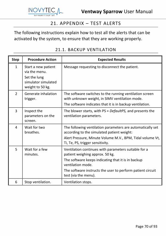
21. APPENDIX – TEST ALERTS
The following instructions explain how to test all the alerts that can be
activated by the system, to ensure that they are working properly.
21.1. BACKUP VENTILATION
Step Procedure Action Expected Results
1 Start a new patient via the menu.
Set the lung simulator simulated weight to 50 kg.
Message requesting to disconnect the patient.
2 Generate inhalation trigger.
The software switches to the running ventilation screen with unknown weight, in SIMV ventilation mode.
The software indicates that it is in backup ventilation.
3 Inspect the parameters on the screen.
The blower starts, with PS = DefaultPS, and presents the ventilation parameters.
4 Wait for two breathes.
The following ventilation parameters are automatically set according to the simulated patient weight:
Alert Pressure, Minute Volume M.V., BPM, Tidal volume Vt, Ti, Te, PS, trigger sensitivity.
5 Wait for a few minutes.
Ventilation continues with parameters suitable for a patient weighing approx. 50 kg.
The software keeps indicating that it is in backup ventilation mode.
The software instructs the user to perform patient circuit test (via the menu).
6 Stop ventilation. Ventilation stops.
Ventway Sparrow User Manual
Page 71 of 93
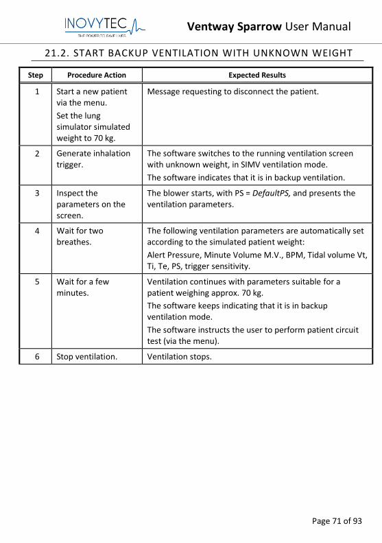
21.2. START BACKUP VENTILATION WITH UNKNOWN WEIGHT
Step Procedure Action Expected Results
1 Start a new patient via the menu.
Set the lung simulator simulated weight to 70 kg.
Message requesting to disconnect the patient.
2 Generate inhalation trigger.
The software switches to the running ventilation screen with unknown weight, in SIMV ventilation mode.
The software indicates that it is in backup ventilation.
3 Inspect the parameters on the screen.
The blower starts, with PS = DefaultPS, and presents the ventilation parameters.
4 Wait for two breathes.
The following ventilation parameters are automatically set according to the simulated patient weight:
Alert Pressure, Minute Volume M.V., BPM, Tidal volume Vt, Ti, Te, PS, trigger sensitivity.
5 Wait for a few minutes.
Ventilation continues with parameters suitable for a patient weighing approx. 70 kg.
The software keeps indicating that it is in backup ventilation mode.
The software instructs the user to perform patient circuit test (via the menu).
6 Stop ventilation. Ventilation stops.
Ventway Sparrow User Manual
Page 72 of 93
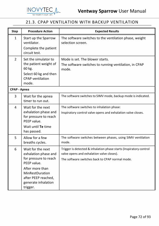
21.3. CPAP VENTILATION WITH BACKUP VENTILATION
Step Procedure Action Expected Results
1 Start up the Sparrow ventilator.
Complete the patient circuit test.
The software switches to the ventilation phase, weight selection screen.
2 Set the simulator to the patient weight of 60 kg.
Select 60 kg and then CPAP ventilation mode.
Mode is set. The blower starts.
The software switches to running ventilation, in CPAP mode.
CPAP - Apnea
3 Wait for the apnea timer to run out.
The software switches to SIMV mode, backup mode is indicated.
4 Wait for the next exhalation phase and for pressure to reach PEEP value.
Wait until Te time has passed.
The software switches to inhalation phase:
Inspiratory control valve opens and exhalation valve closes.
5 Allow for a few breaths cycles.
The software switches between phases, using SIMV ventilation
mode.
6 Wait for the next exhalation phase and for pressure to reach PEEP value.
After more than MinRestDuration after PEEP reached, generate inhalation trigger.
Trigger is detected & inhalation phase starts (Inspiratory control
valve opens and exhalation valve closes).
The software switches back to CPAP normal mode.
Ventway Sparrow User Manual
Page 73 of 93
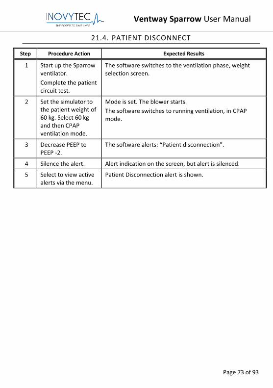
21.4. PATIENT DISCONNECT
Step Procedure Action Expected Results
1 Start up the Sparrow ventilator.
Complete the patient circuit test.
The software switches to the ventilation phase, weight selection screen.
2 Set the simulator to the patient weight of 60 kg. Select 60 kg and then CPAP ventilation mode.
Mode is set. The blower starts.
The software switches to running ventilation, in CPAP mode.
3 Decrease PEEP to PEEP -2.
The software alerts: “Patient disconnection”.
4 Silence the alert. Alert indication on the screen, but alert is silenced.
5 Select to view active alerts via the menu.
Patient Disconnection alert is shown.
Ventway Sparrow User Manual
Page 74 of 93
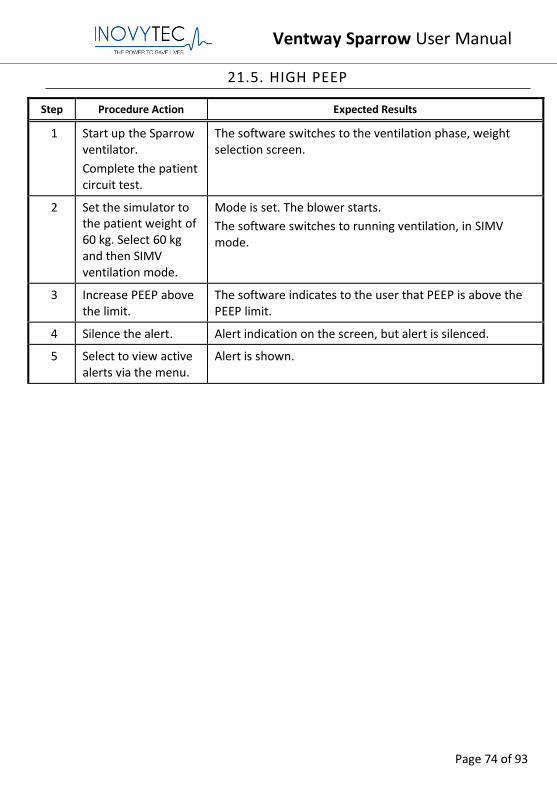
21.5. HIGH PEEP
Step Procedure Action Expected Results
1 Start up the Sparrow ventilator.
Complete the patient circuit test.
The software switches to the ventilation phase, weight selection screen.
2 Set the simulator to the patient weight of 60 kg. Select 60 kg and then SIMV ventilation mode.
Mode is set. The blower starts.
The software switches to running ventilation, in SIMV mode.
3 Increase PEEP above the limit.
The software indicates to the user that PEEP is above the PEEP limit.
4 Silence the alert. Alert indication on the screen, but alert is silenced.
5 Select to view active alerts via the menu.
Alert is shown.
Ventway Sparrow User Manual
Page 75 of 93
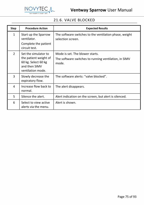
21.6. VALVE BLOCKED
Step Procedure Action Expected Results
1 Start up the Sparrow ventilator.
Complete the patient circuit test.
The software switches to the ventilation phase, weight
selection screen.
2 Set the simulator to the patient weight of 60 kg. Select 60 kg and then SIMV ventilation mode.
Mode is set. The blower starts.
The software switches to running ventilation, in SIMV
mode.
3 Slowly decrease the expiratory flow.
The software alerts: “valve blocked”.
4 Increase flow back to normal.
The alert disappears.
5 Silence the alert. Alert indication on the screen, but alert is silenced.
6 Select to view active alerts via the menu.
Alert is shown.
Ventway Sparrow User Manual
Page 76 of 93
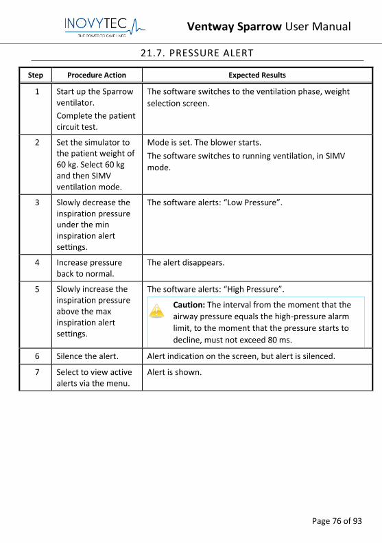
21.7. PRESSURE ALERT
Step Procedure Action Expected Results
1 Start up the Sparrow ventilator.
Complete the patient circuit test.
The software switches to the ventilation phase, weight
selection screen.
2 Set the simulator to the patient weight of 60 kg. Select 60 kg and then SIMV ventilation mode.
Mode is set. The blower starts.
The software switches to running ventilation, in SIMV
mode.
3 Slowly decrease the inspiration pressure under the min inspiration alert settings.
The software alerts: “Low Pressure”.
4 Increase pressure back to normal.
The alert disappears.
5 Slowly increase the inspiration pressure above the max inspiration alert settings.
The software alerts: “High Pressure”.
Caution: The interval from the moment that the
airway pressure equals the high-pressure alarm
limit, to the moment that the pressure starts to
decline, must not exceed 80 ms.
6 Silence the alert. Alert indication on the screen, but alert is silenced.
7 Select to view active alerts via the menu.
Alert is shown.
Ventway Sparrow User Manual
Page 77 of 93
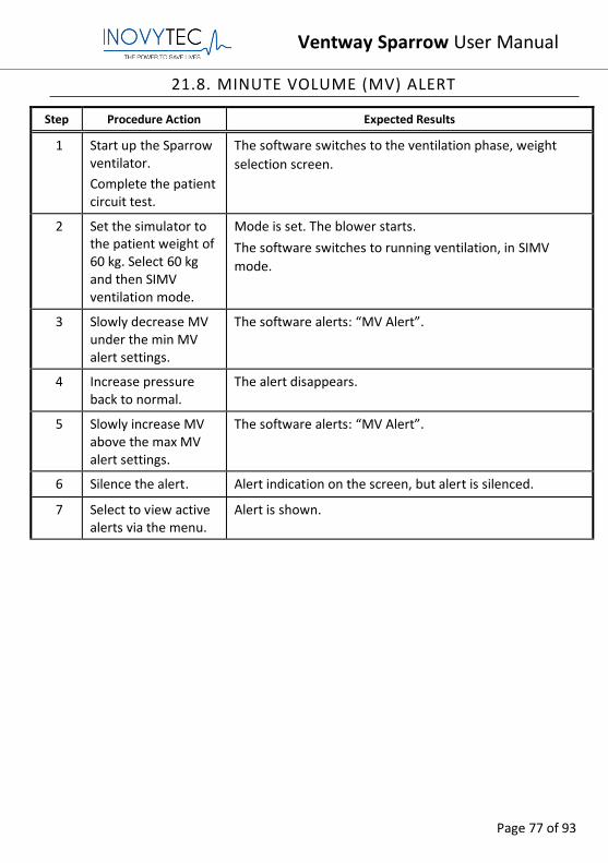
21.8. MINUTE VOLUME (MV) ALERT
Step Procedure Action Expected Results
1 Start up the Sparrow ventilator.
Complete the patient circuit test.
The software switches to the ventilation phase, weight
selection screen.
2 Set the simulator to the patient weight of 60 kg. Select 60 kg and then SIMV ventilation mode.
Mode is set. The blower starts.
The software switches to running ventilation, in SIMV
mode.
3 Slowly decrease MV under the min MV alert settings.
The software alerts: “MV Alert”.
4 Increase pressure back to normal.
The alert disappears.
5 Slowly increase MV above the max MV alert settings.
The software alerts: “MV Alert”.
6 Silence the alert. Alert indication on the screen, but alert is silenced.
7 Select to view active alerts via the menu.
Alert is shown.
Ventway Sparrow User Manual
Page 78 of 93
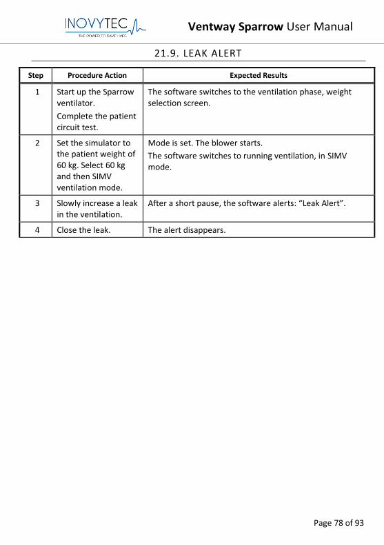
21.9. LEAK ALERT
Step Procedure Action Expected Results
1 Start up the Sparrow ventilator.
Complete the patient circuit test.
The software switches to the ventilation phase, weight selection screen.
2 Set the simulator to the patient weight of 60 kg. Select 60 kg and then SIMV ventilation mode.
Mode is set. The blower starts.
The software switches to running ventilation, in SIMV mode.
3 Slowly increase a leak in the ventilation.
After a short pause, the software alerts: “Leak Alert”.
4 Close the leak. The alert disappears.
Ventway Sparrow User Manual
Page 79 of 93
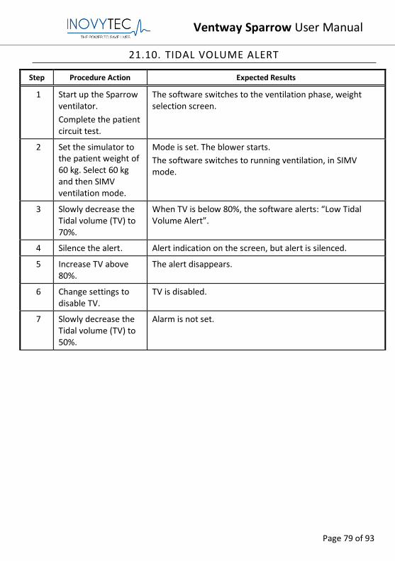
21.10. TIDAL VOLUME ALERT
Step Procedure Action Expected Results
1 Start up the Sparrow ventilator.
Complete the patient circuit test.
The software switches to the ventilation phase, weight selection screen.
2 Set the simulator to the patient weight of 60 kg. Select 60 kg and then SIMV ventilation mode.
Mode is set. The blower starts.
The software switches to running ventilation, in SIMV mode.
3 Slowly decrease the Tidal volume (TV) to 70%.
When TV is below 80%, the software alerts: “Low Tidal Volume Alert”.
4 Silence the alert. Alert indication on the screen, but alert is silenced.
5 Increase TV above 80%.
The alert disappears.
6 Change settings to disable TV.
TV is disabled.
7 Slowly decrease the Tidal volume (TV) to 50%.
Alarm is not set.
Ventway Sparrow User Manual
Page 80 of 93
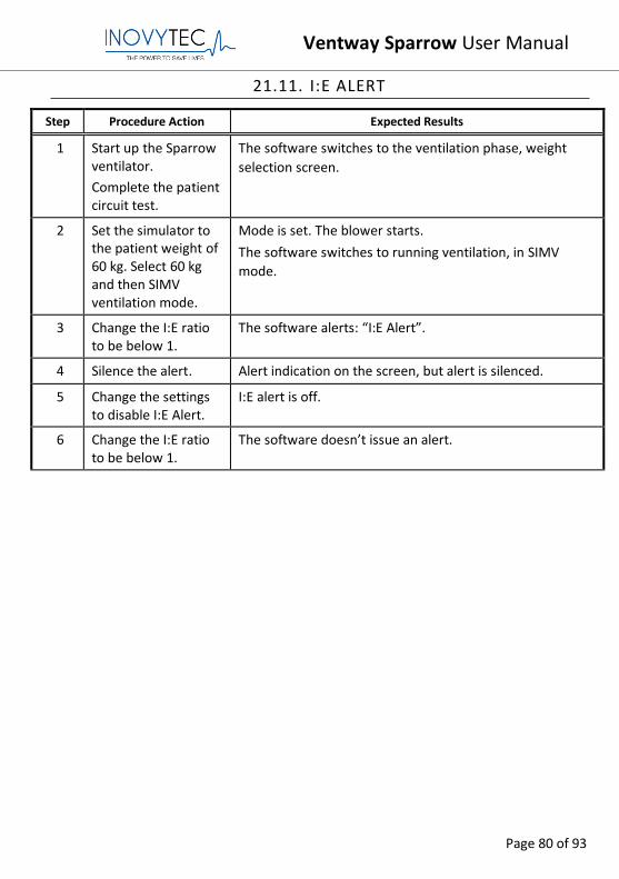
21.11. I:E ALERT
Step Procedure Action Expected Results
1 Start up the Sparrow ventilator.
Complete the patient circuit test.
The software switches to the ventilation phase, weight
selection screen.
2 Set the simulator to the patient weight of 60 kg. Select 60 kg and then SIMV ventilation mode.
Mode is set. The blower starts.
The software switches to running ventilation, in SIMV
mode.
3 Change the I:E ratio to be below 1.
The software alerts: “I:E Alert”.
4 Silence the alert. Alert indication on the screen, but alert is silenced.
5 Change the settings to disable I:E Alert.
I:E alert is off.
6 Change the I:E ratio to be below 1.
The software doesn’t issue an alert.
Ventway Sparrow User Manual
Page 81 of 93
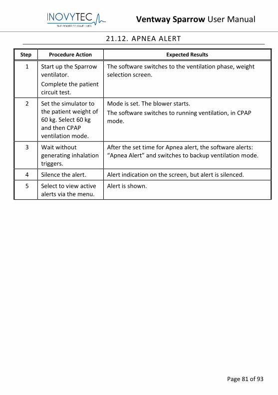
21.12. APNEA ALERT
Step Procedure Action Expected Results
1 Start up the Sparrow ventilator.
Complete the patient circuit test.
The software switches to the ventilation phase, weight selection screen.
2 Set the simulator to the patient weight of 60 kg. Select 60 kg and then CPAP ventilation mode.
Mode is set. The blower starts.
The software switches to running ventilation, in CPAP mode.
3 Wait without generating inhalation triggers.
After the set time for Apnea alert, the software alerts: “Apnea Alert” and switches to backup ventilation mode.
4 Silence the alert. Alert indication on the screen, but alert is silenced.
5 Select to view active alerts via the menu.
Alert is shown.
Ventway Sparrow User Manual
Page 82 of 93
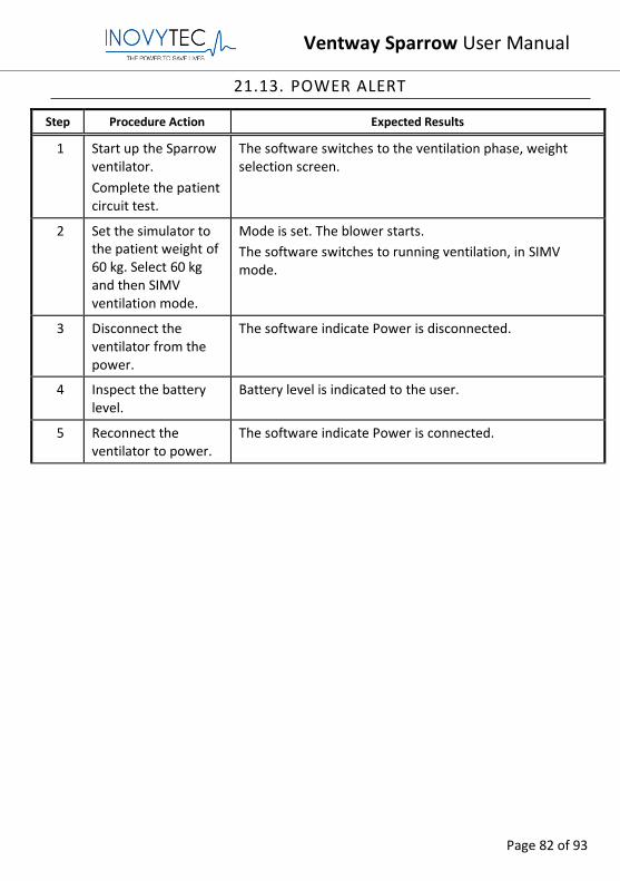
21.13. POWER ALERT
Step Procedure Action Expected Results
1 Start up the Sparrow ventilator.
Complete the patient circuit test.
The software switches to the ventilation phase, weight selection screen.
2 Set the simulator to the patient weight of 60 kg. Select 60 kg and then SIMV ventilation mode.
Mode is set. The blower starts.
The software switches to running ventilation, in SIMV mode.
3 Disconnect the ventilator from the power.
The software indicate Power is disconnected.
4 Inspect the battery level.
Battery level is indicated to the user.
5 Reconnect the ventilator to power.
The software indicate Power is connected.
Ventway Sparrow User Manual
Page 83 of 93
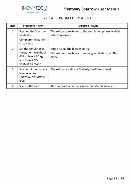
21.14. LOW BATTERY ALERT
Step Procedure Action Expected Results
1 Start up the Sparrow ventilator.
Complete the patient circuit test.
The software switches to the ventilation phase, weight selection screen.
2 Set the simulator to the patient weight of 60 kg. Select 60 kg and then SIMV ventilation mode.
Mode is set. The blower starts.
The software switches to running ventilation, in SIMV mode.
3 Wait until the battery level reaches CriticallyLowBattery level.
The software indicate CriticallyLowBattery level.
4 Silence the alert. Alert indication on the screen, but alert is silenced.
Ventway Sparrow User Manual
Page 84 of 93
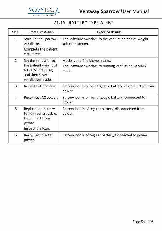
21.15. BATTERY TYPE ALERT
Step Procedure Action Expected Results
1 Start up the Sparrow ventilator.
Complete the patient circuit test.
The software switches to the ventilation phase, weight selection screen.
2 Set the simulator to the patient weight of 60 kg. Select 60 kg and then SIMV ventilation mode.
Mode is set. The blower starts.
The software switches to running ventilation, in SIMV mode.
3 Inspect battery icon. Battery icon is of rechargeable battery, disconnected from power.
4 Reconnect AC power. Battery icon is of rechargeable battery, connected to power.
5 Replace the battery to non-rechargeable. Disconnect from power.
Inspect the icon.
Battery icon is of regular battery, disconnected from power.
6 Reconnect the AC power.
Battery icon is of regular battery, Connected to power.
Ventway Sparrow User Manual
Page 85 of 93
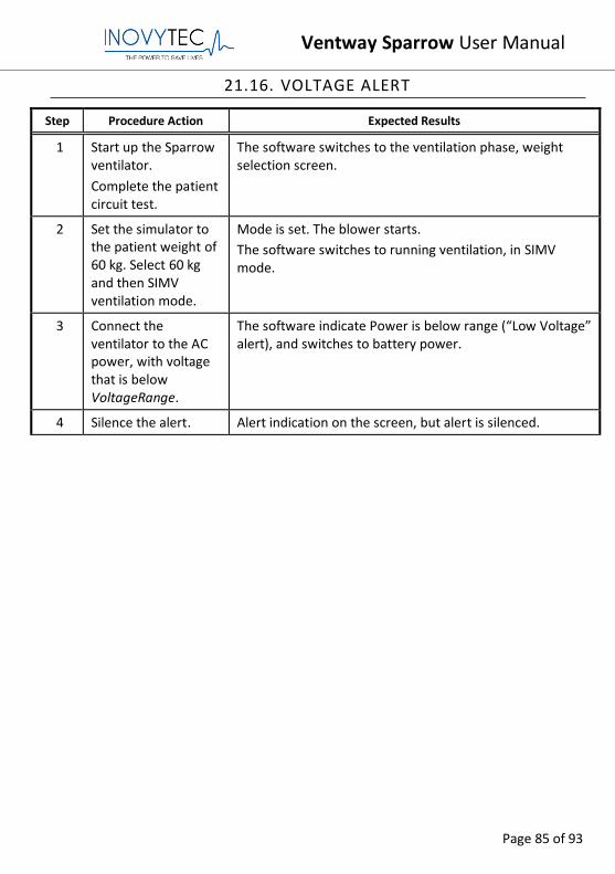
21.16. VOLTAGE ALERT
Step Procedure Action Expected Results
1 Start up the Sparrow ventilator.
Complete the patient circuit test.
The software switches to the ventilation phase, weight selection screen.
2 Set the simulator to the patient weight of 60 kg. Select 60 kg and then SIMV ventilation mode.
Mode is set. The blower starts.
The software switches to running ventilation, in SIMV mode.
3 Connect the ventilator to the AC power, with voltage that is below VoltageRange.
The software indicate Power is below range (“Low Voltage” alert), and switches to battery power.
4 Silence the alert. Alert indication on the screen, but alert is silenced.
Ventway Sparrow User Manual
Page 86 of 93
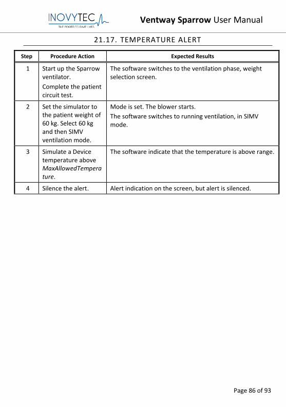
21.17. TEMPERATURE ALERT
Step Procedure Action Expected Results
1 Start up the Sparrow ventilator.
Complete the patient circuit test.
The software switches to the ventilation phase, weight selection screen.
2 Set the simulator to the patient weight of 60 kg. Select 60 kg and then SIMV ventilation mode.
Mode is set. The blower starts.
The software switches to running ventilation, in SIMV mode.
3 Simulate a Device temperature above MaxAllowedTemperature.
The software indicate that the temperature is above range.
4 Silence the alert. Alert indication on the screen, but alert is silenced.
Ventway Sparrow User Manual
Page 87 of 93
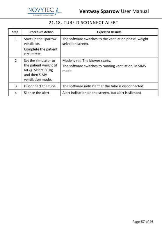
21.18. TUBE DISCONNECT ALERT
Step Procedure Action Expected Results
1 Start up the Sparrow ventilator.
Complete the patient circuit test.
The software switches to the ventilation phase, weight selection screen.
2 Set the simulator to the patient weight of 60 kg. Select 60 kg and then SIMV ventilation mode.
Mode is set. The blower starts.
The software switches to running ventilation, in SIMV mode.
3 Disconnect the tube. The software indicate that the tube is disconnected.
4 Silence the alert. Alert indication on the screen, but alert is silenced.
Ventway Sparrow User Manual
Page 88 of 93
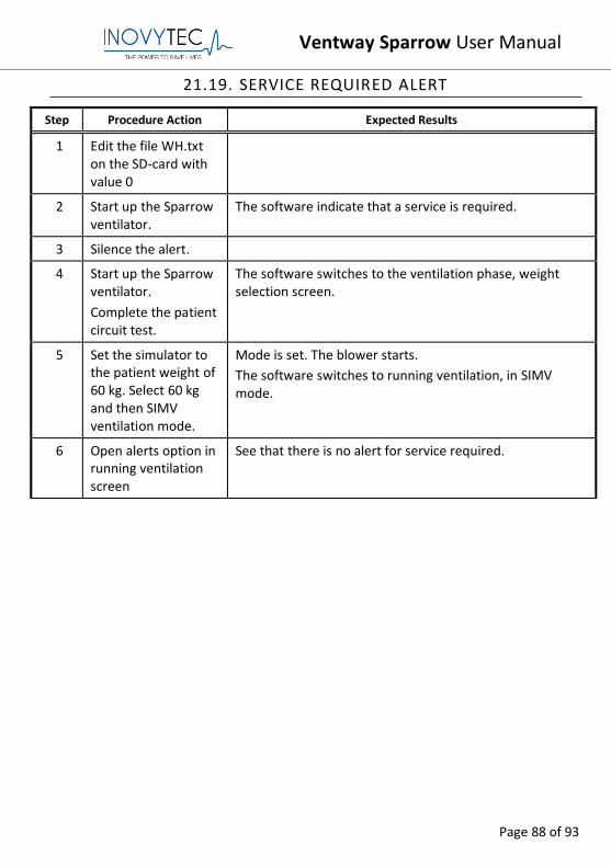
21.19. SERVICE REQUIRED ALERT
Step Procedure Action Expected Results
1 Edit the file WH.txt on the SD-card with value 0
2 Start up the Sparrow ventilator.
The software indicate that a service is required.
3 Silence the alert.
4 Start up the Sparrow ventilator.
Complete the patient circuit test.
The software switches to the ventilation phase, weight selection screen.
5 Set the simulator to the patient weight of 60 kg. Select 60 kg and then SIMV ventilation mode.
Mode is set. The blower starts.
The software switches to running ventilation, in SIMV mode.
6 Open alerts option in running ventilation screen
See that there is no alert for service required.
Ventway Sparrow User Manual
Page 89 of 93
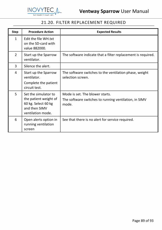
21.20. FILTER REPLACEMENT REQUIRED
Step Procedure Action Expected Results
1 Edit the file WH.txt on the SD-card with value 882000.
2 Start up the Sparrow ventilator.
The software indicate that a filter replacement is required.
3 Silence the alert.
4 Start up the Sparrow ventilator.
Complete the patient circuit test.
The software switches to the ventilation phase, weight selection screen.
5 Set the simulator to the patient weight of 60 kg. Select 60 kg and then SIMV ventilation mode.
Mode is set. The blower starts.
The software switches to running ventilation, in SIMV mode.
6 Open alerts option in running ventilation screen
See that there is no alert for service required.
Ventway Sparrow User Manual
Page 90 of 93
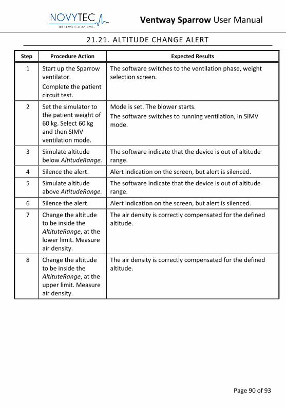
21.21. ALTITUDE CHANGE ALERT
Step Procedure Action Expected Results
1 Start up the Sparrow ventilator.
Complete the patient circuit test.
The software switches to the ventilation phase, weight selection screen.
2 Set the simulator to the patient weight of 60 kg. Select 60 kg and then SIMV ventilation mode.
Mode is set. The blower starts.
The software switches to running ventilation, in SIMV mode.
3 Simulate altitude below AltitudeRange.
The software indicate that the device is out of altitude range.
4 Silence the alert. Alert indication on the screen, but alert is silenced.
5 Simulate altitude above AltitudeRange.
The software indicate that the device is out of altitude range.
6 Silence the alert. Alert indication on the screen, but alert is silenced.
7 Change the altitude to be inside the AltituteRange, at the lower limit. Measure air density.
The air density is correctly compensated for the defined altitude.
8 Change the altitude to be inside the AltituteRange, at the upper limit. Measure air density.
The air density is correctly compensated for the defined altitude.

Ventway Sparrow User Manual
Page 91 of 93
21.22. SHUTDOWN ALERT
Step Procedure Action Expected Results
1 Start up the Sparrow ventilator.
Complete the patient circuit test.
The software switches to the ventilation phase, weight selection screen.
2 Set the simulator to the patient weight of 60 kg. Select 60 kg and then SIMV ventilation mode.
Mode is set. The blower starts.
The software switches to running ventilation, in SIMV mode.
3 Shut the device down by long press on the on/off button.
The software requires confirmation for shutting down.
4 The device starts playing a tone until an extra confirmation.
The device shuts down.

Ventway Sparrow User Manual
Page 92 of 93
21.23. VENTILATION DURING STANDBY (DUE TO PATIENT
INSPIRATORY EFFORT)
Step Procedure Action Expected Results
1 Start up the Sparrow ventilator.
Complete the patient circuit test.
The software switches to the ventilation phase, weight selection screen.
2 Set the simulator to the patient weight of 60 kg. Select 60 kg and then SIMV ventilation mode.
Mode is set. The blower starts.
The software switches to running ventilation, in SIMV mode.
3 Put the device in standby via the menu.
The blower stops.
4 Generate inhalation trigger.
The blower starts.
The software switches to the running ventilation screen, continuing the previous ventilation with the same parameters.
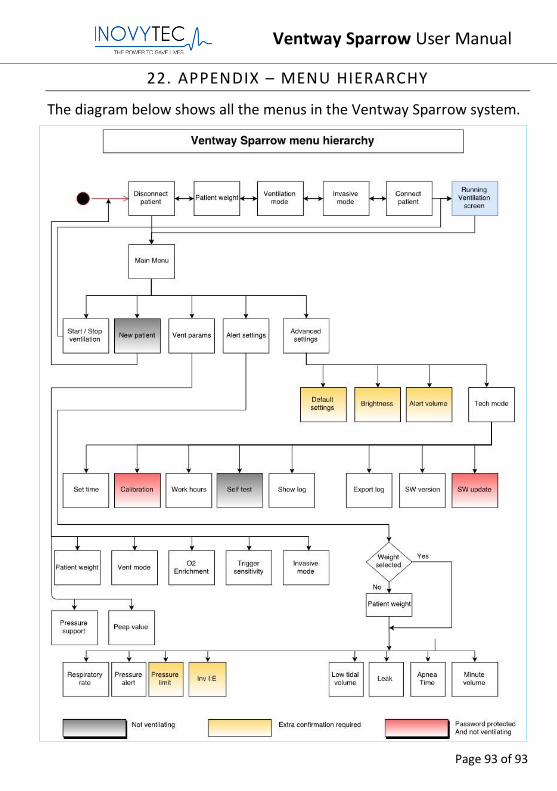
Ventway Sparrow User Manual
Page 93 of 93
22. APPENDIX – MENU HIERARCHY
The diagram below shows all the menus in the Ventway Sparrow system.