Embed Size (px)
Citation preview
VENTURA 150—200T
MPC-5000
INSTALLATION AND OWNER’S MANUAL
Section 1…………..Installation, Operation, Maintenance
Section 2………………….……...Controls & Programming
Spectra Watermakers, Inc.
20 Mariposa Road, San Rafael, CA 94901
Phone 415-526-2780 Fax 415-526-2787
www.spectrawatermakers.com
Rev. 12/11

2

3
Table of Contents
Section 1
Installation
Operation
Getting Started .....................................................................................................................4
Introduction ..........................................................................................................................5
Suggested Spares .................................................................................................................6
Installation Basics ................................................................................................................7
Ventura Plumbing Schematic ..............................................................................................8
Product Water plumbing ......................................................................................................9
Tube Fitting Assembly Procedures ....................................................................................10
Wiring ................................................................................................................................11
Salinity Probe Installation ..................................................................................................13
MPC Tank Switch Wiring and operation ...........................................................................14
Z Brane Installation ............................................................................................................38
Membrane Pressure Vessel Relocation ..............................................................................42
Feed Pump Relocation .......................................................................................................44
Page Number
New Systems Start Up and Testing ...................................................................................16
Dry Testing with an Artificial Ocean.................................................................................19
Fresh Water Flush Adjustment ..........................................................................................20
Normal Start Up Using the Auto Run ................................................................................21
Manual Operation ..............................................................................................................22
Service & Maintenance
Long Term Storage Procedures .........................................................................................23
Winterizing ........................................................................................................................25
Maintenance .......................................................................................................................26
Membranes .........................................................................................................................27
Membrane Cleaning Procedure ..........................................................................................30
Troubleshooting Procedures, Service Bulletins .................................................................31
Part Numbers ....................................................................................................................45
Clark Pump ........................................................................................................................50
Wiring Schematic ...............................................................................................................54
Section 2: Programming & Controls
Begins after pg 54
4
Unpack the system and inspect it to make sure it has not been damaged in shipment.
Refer to the shipping list for your system to make sure you have received all of the components
listed. Do not discard any packaging until you have found and identified all of the parts. The
small installation parts are listed on the kit list.
Warning! We will not be held responsible for shortages and/or freight damage that are not
reported within thirty days of the ship date.
Study the system plumbing and wiring diagrams before beginning your installation. This will
assist you in understanding the function of each component.
Layout the system. Before starting the installation, identify where each module and component
will be placed. Insure that there is proper clearance around the components for removal of fil-
ters and system service. Also check to make sure you have adequate tubing and hose before
starting so additional parts may be ordered.
THE VENTURA 200T IS DESIGNED FOR WARM WATER USE ONLY. DO NOT OPERATE
IN WATERS BELOW 50
0
F (10
0
C)
Getting Started
Ventura 150 MPC Shipping List
MPC 5000
Accumulator Assembly
High Pressure Clark Pump and Reverse Osmosis Membrane
Black High Pressure Filter Housings
Feed Pump Inlet Assembly with Fresh Water Flush
Ventura MPC Install Kit
Ventura MPC Kit
Service Kit
Two 5/8” Hose (25’)
5
Introduction to the Ventura 150 MPC
The Ventura represents the finest watermaker for small and midsized yachts available to-
day. The Spectra Clark Pump is matched to a 21” high rejection membrane. Properly in-
stalled and maintained it will supply years of reliable service. The MPC-5000 control pro-
The Spectra Intensifier, known as the Clark Pump, was introduced in 1997 and has continu-
ally improved since. It holds a lifetime warranty for the original purchaser! It is built of mod-
ern non-corrosive composites and has a 21” high rejection membrane.
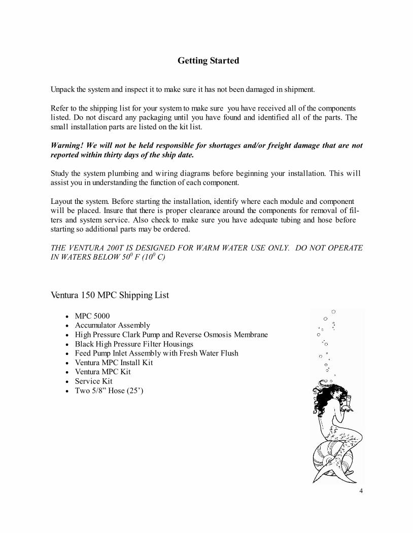
Front View
Pressure relief valve
Quick disconnect fitting to
facilitate maintenance.
Double rubber mounts
to absorb vibration
Fresh Water
Flush Solenoid
Service
Port
Service
Valve
Cooling
Fan
Motor
Shurflo
Feed
Pump
The Clark Pump Membrane Module. Pre -
mounted and plumbed together as a single
unit. Saves time and adds reliability.
Ventura Feed Pump Module.
Includes the feed pump, cooling fan, charcoal filter for the
flushing system, flush solenoid, service valve, and service
port. The module has compact and streamlined plumbing.
6
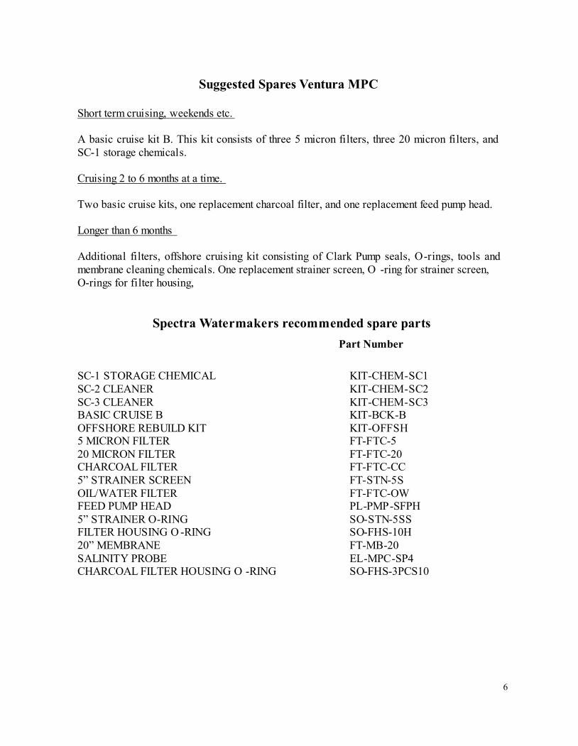
Suggested Spares Ventura MPC
Short term cruising, weekends etc.
A basic cruise kit B. This kit consists of three 5 micron filters, three 20 micron filters, and
SC-1 storage chemicals.
Cruising 2 to 6 months at a time.
Two basic cruise kits, one replacement charcoal filter, and one replacement feed pump head.
Longer than 6 months
Additional filters, offshore cruising kit consisting of Clark Pump seals, O-rings, tools and
membrane cleaning chemicals. One replacement strainer screen, O -ring for strainer screen,
O-rings for filter housing,
Spectra Watermakers recommended spare parts
SC-1 STORAGE CHEMICAL KIT-CHEM-SC1
SC-2 CLEANER KIT-CHEM-SC2
SC-3 CLEANER KIT-CHEM-SC3
BASIC CRUISE B KIT-BCK-B
OFFSHORE REBUILD KIT KIT-OFFSH
5 MICRON FILTER FT-FTC-5
20 MICRON FILTER FT-FTC-20
CHARCOAL FILTER FT-FTC-CC
5” STRAINER SCREEN FT-STN-5S
OIL/WATER FILTER FT-FTC-OW
FEED PUMP HEAD PL-PMP-SFPH
5” STRAINER O-RING SO-STN-5SS
FILTER HOUSING O -RING SO-FHS-10H
20” MEMBRANE FT-MB-20
SALINITY PROBE EL-MPC-SP4
CHARCOAL FILTER HOUSING O -RING SO-FHS-3PCS10
Part Number
7
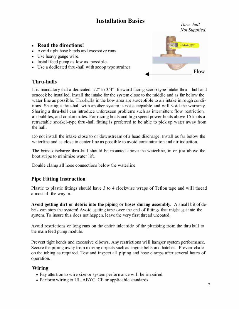
Installation Basics
Read the directions!
Avoid tight hose bends and excessive runs.
Use heavy gauge wire.
Install feed pump as low as possible.
Use a dedicated thru -hull with scoop type strainer.
Thru-hulls
It is mandatory that a dedicated 1/2” to 3/4” forward facing scoop type intake thru -hull and
seacock be installed. Install the intake for the system close to the middle and as far below the
water line as possible. Thru-hulls in the bow area are susceptible to air intake in rough condi-
tions. Sharing a thru -hull with another system is not acceptable and will void the warranty.
Sharing a thru -hull can introduce unforeseen problems such as intermittent flow restriction,
air bubbles, and contaminates. For racing boats and high speed power boats above 15 knots a
retractable snorkel-type thru -hull fitting is preferred to be able to pick up water away from
the hull.
Do not install the intake close to or downstream of a head discharge. Install as far below the
waterline and as close to center line as possible to avoid contamination and air induction.
The brine discharge thru -hull should be mounted above the waterline, in or just above the
boot stripe to minimize water lift.
Double clamp all hose connections below the waterline.
Pipe Fitting Instruction
Plastic to plastic fittings should have 3 to 4 clockwise wraps of Teflon tape and will thread
almost all the way in.
Avoid getting dirt or debris into the piping or hoses during assembly. A small bit of de-
bris can stop the system! Avoid getting tape over the end of fittings that might get into the
system. To insure this does not happen, leave the very first thread uncoated.
Avoid restrictions or long runs on the entire inlet side of the plumbing from the thru hull to
the main feed pump module.
Prevent tight bends and excessive elbows. Any restrictions will hamper system performance.
Secure the piping away from moving objects such as engine belts and hatches. Prevent chafe
on the tubing as required. Test and inspect all piping and hose clamps after several hours of
operation.
Flow
Wiring
Pay attention to wire size or system performance will be impaired
Perform wiring to UL, ABYC, CE or applicable standards
Thru- hull
Not Supplied.
8
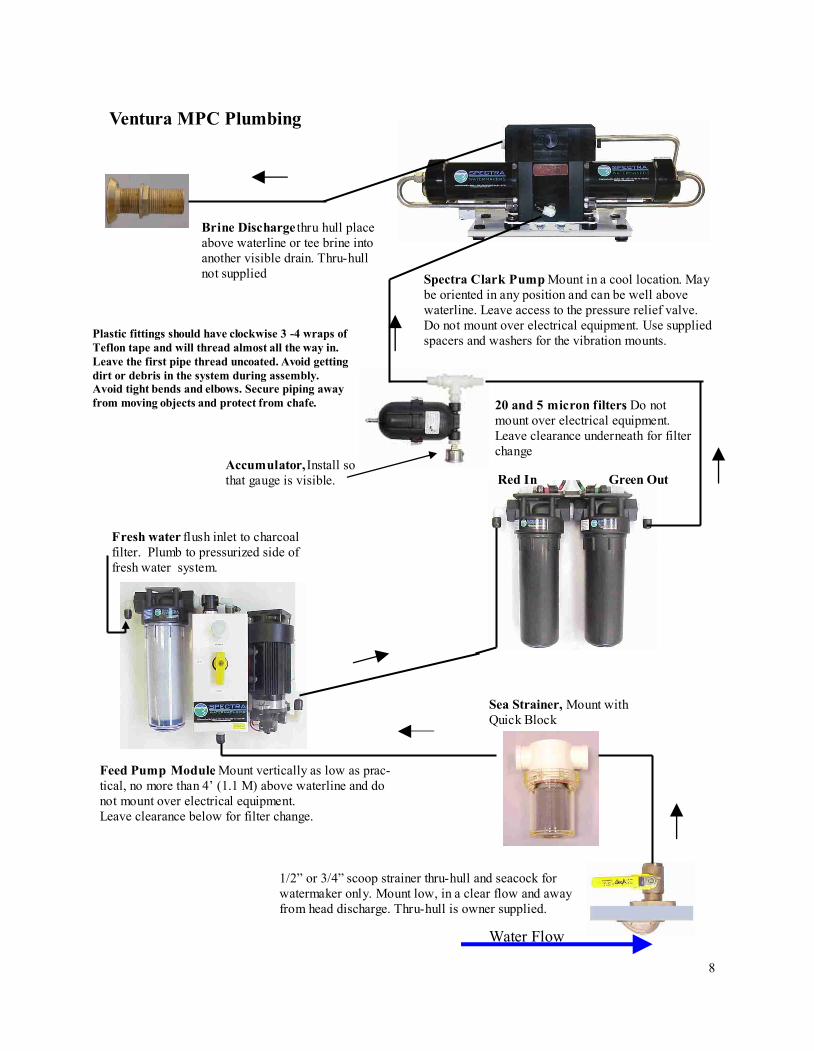
Water Flow
Sea Strainer, Mount with
Quick Block
Ventura MPC Plumbing
Feed Pump Module. Mount vertically as low as prac-
tical, no more than 4’ (1.1 M) above waterline and do
not mount over electrical equipment.
Leave clearance below for filter change.
20 and 5 micron filters. Do not
mount over electrical equipment.
Leave clearance underneath for filter
change
Accumulator, Install so
that gauge is visible.
Plastic fittings should have clockwise 3 -4 wraps of
Teflon tape and will thread almost all the way in.
Leave the first pipe thread uncoated. Avoid getting
dirt or debris in the system during assembly.
Avoid tight bends and elbows. Secure piping away
from moving objects and protect from chafe.
Fresh water flush inlet to charcoal
filter. Plumb to pressurized side of
fresh water system.
Spectra Clark Pump. Mount in a cool location. May
be oriented in any position and can be well above
waterline. Leave access to the pressure relief valve.
Do not mount over electrical equipment. Use supplied
spacers and washers for the vibration mounts.
Brine Discharge thru hull place
above waterline or tee brine into
another visible drain. Thru-hull
not supplied
1/2” or 3/4” scoop strainer thru-hull and seacock for
watermaker only. Mount low, in a clear flow and away
from head discharge. Thru-hull is owner supplied.
Red In Green Out
9
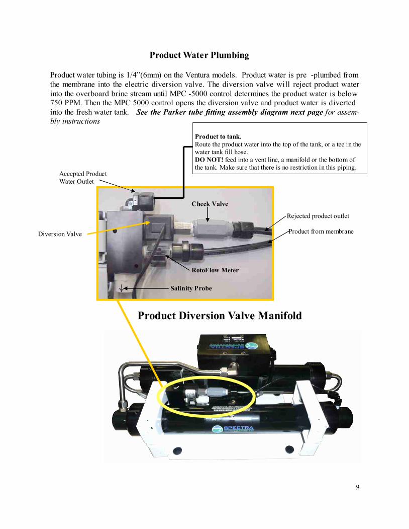
Product to tank.
Route the product water into the top of the tank, or a tee in the
water tank fill hose.
DO NOT! feed into a vent line, a manifold or the bottom of
the tank. Make sure that there is no restriction in this piping.
Product Water Plumbing
Salinity Probe
Diversion Valve
Product water tubing is 1/4”(6mm) on the Ventura models. Product water is pre -plumbed from
the membrane into the electric diversion valve. The diversion valve will reject product water
into the overboard brine stream until MPC -5000 control determines the product water is below
750 PPM. Then the MPC 5000 control opens the diversion valve and product water is diverted
into the fresh water tank. See the Parker tube fitting assembly diagram next page for assem-
bly instructions
Product Diversion Valve Manifold
RotoFlow Meter
Accepted Product
Water Outlet
Rejected product outlet
Product from membrane
Check Valve
10
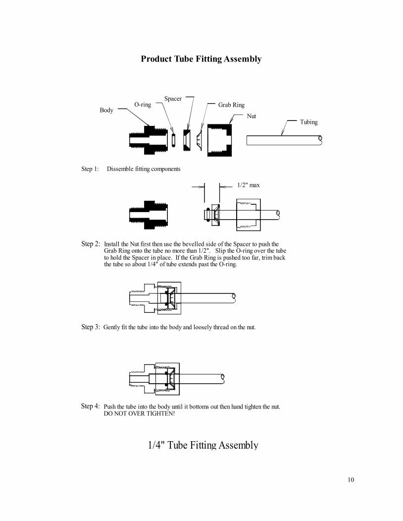
Gently fit the tube into the body and loosely thread on the nut.
Push the tube into the body until it bottoms out then hand tighten the nut.
DO NOT OVER TIGHTEN!
1/4" Tube Fitting Assembly
Install the Nut first then use the bevelled side of the Spacer to push the
Grab Ring onto the tube no more than 1/2". Slip the O-ring over the tube
to hold the Spacer in place. If the Grab Ring is pushed too far, trim back
the tube so about 1/4" of tube extends past the O-ring.
Step 4:
Step 3:
Step 2:
Step 1: Dissemble fitting components
Body
O-ring
Spacer
1/2" max
Grab Ring
Nut
Tubing
Product Tube Fitting Assembly
11
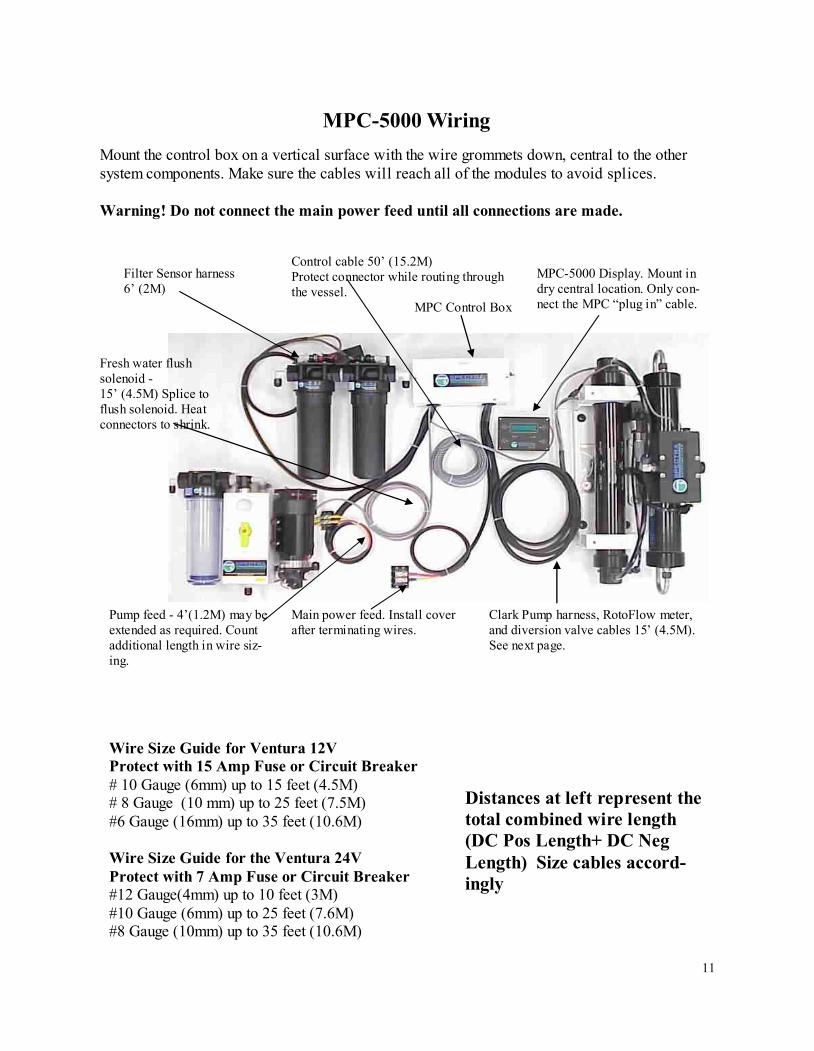
MPC-5000 Wiring
Mount the control box on a vertical surface with the wire grommets down, central to the other
system components. Make sure the cables will reach all of the modules to avoid splices.
Warning! Do not connect the main power feed until all connections are made.
Filter Sensor harness
6’ (2M)
Control cable 50’ (15.2M)
Protect connector while routing through
the vessel.
MPC Control Box
Clark Pump harness, RotoFlow meter,
and diversion valve cables 15’ (4.5M).
See next page.
MPC-5000 Display. Mount in
dry central location. Only con-
nect the MPC “plug in” cable.
Main power feed. Install cover
after terminating wires.
Pump feed - 4’(1.2M) may be
extended as required. Count
additional length in wire siz-
ing.
Fresh water flush
solenoid -
15’ (4.5M) Splice to
flush solenoid. Heat
connectors to shrink.
Wire Size Guide for Ventura 12V
Protect with 15 Amp Fuse or Circuit Breaker
# 10 Gauge (6mm) up to 15 feet (4.5M)
# 8 Gauge (10 mm) up to 25 feet (7.5M)
#6 Gauge (16mm) up to 35 feet (10.6M)
Wire Size Guide for the Ventura 24V
Protect with 7 Amp Fuse or Circuit Breaker
#12 Gauge(4mm) up to 10 feet (3M)
#10 Gauge (6mm) up to 25 feet (7.6M)
#8 Gauge (10mm) up to 35 feet (10.6M)
Distances at left represent the
total combined wire length
(DC Pos Length+ DC Neg
Length) Size cables accord-
ingly
12
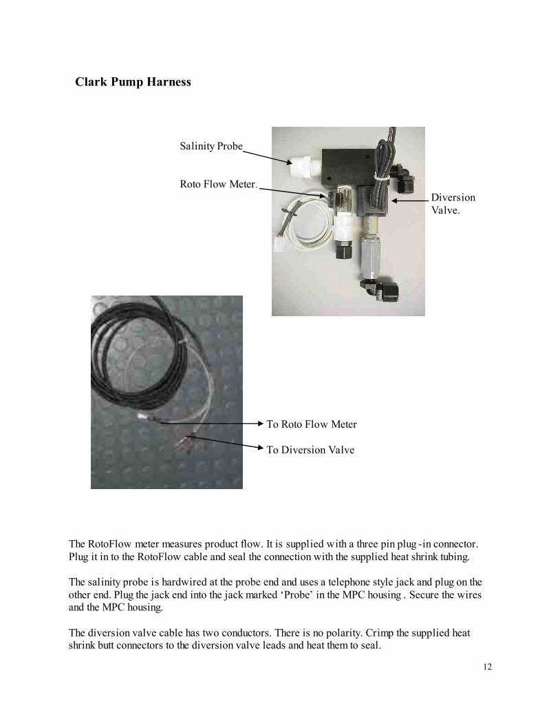
Clark Pump Harness
Diversion
Valve.
Salinity Probe
Roto Flow Meter.
The RotoFlow meter measures product flow. It is supplied with a three pin plug -in connector.
Plug it in to the RotoFlow cable and seal the connection with the supplied heat shrink tubing.
The salinity probe is hardwired at the probe end and uses a telephone style jack and plug on the
other end. Plug the jack end into the jack marked ‘Probe’ in the MPC housing . Secure the wires
and the MPC housing.
The diversion valve cable has two conductors. There is no polarity. Crimp the supplied heat
shrink butt connectors to the diversion valve leads and heat them to seal.
To Roto Flow Meter
To Diversion Valve
13
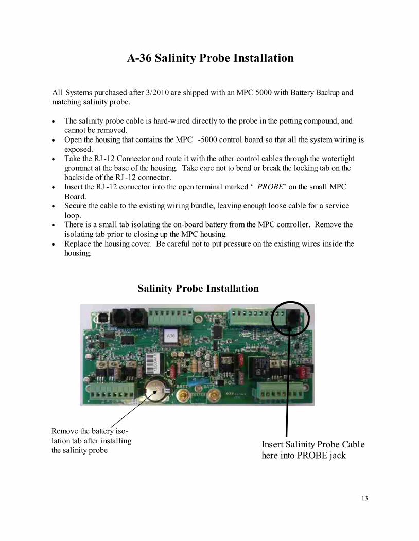
All Systems purchased after 3/2010 are shipped with an MPC 5000 with Battery Backup and
matching salinity probe.
The salinity probe cable is hard-wired directly to the probe in the potting compound, and
cannot be removed.
Open the housing that contains the MPC -5000 control board so that all the system wiring is
exposed.
Take the RJ -12 Connector and route it with the other control cables through the watertight
grommet at the base of the housing. Take care not to bend or break the locking tab on the
backside of the RJ -12 connector.
Insert the RJ -12 connector into the open terminal marked ‘ PROBE’ on the small MPC
Board.
Secure the cable to the existing wiring bundle, leaving enough loose cable for a service
loop.
There is a small tab isolating the on-board battery from the MPC controller. Remove the
isolating tab prior to closing up the MPC housing.
Replace the housing cover. Be careful not to put pressure on the existing wires inside the
housing.
A-36 Salinity Probe Installation
Insert Salinity Probe Cable
here into PROBE jack
Salinity Probe Installation
Remove the battery iso-
lation tab after installing
the salinity probe
14
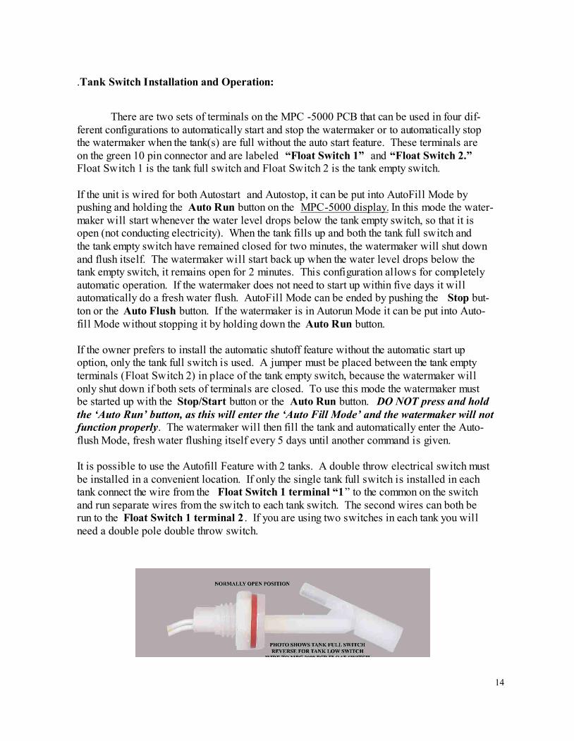
.Tank Switch Installation and Operation:
There are two sets of terminals on the MPC -5000 PCB that can be used in four dif-
ferent configurations to automatically start and stop the watermaker or to automatically stop
the watermaker when the tank(s) are full without the auto start feature. These terminals are
on the green 10 pin connector and are labeled “Float Switch 1” and “Float Switch 2.”
Float Switch 1 is the tank full switch and Float Switch 2 is the tank empty switch.
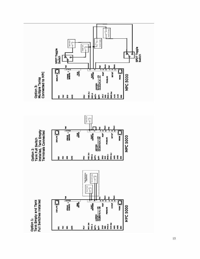
If the unit is wired for both Autostart and Autostop, it can be put into AutoFill Mode by
pushing and holding the Auto Run button on the MPC-5000 display. In this mode the water-
maker will start whenever the water level drops below the tank empty switch, so that it is
open (not conducting electricity). When the tank fills up and both the tank full switch and
the tank empty switch have remained closed for two minutes, the watermaker will shut down
and flush itself. The watermaker will start back up when the water level drops below the
tank empty switch, it remains open for 2 minutes. This configuration allows for completely
automatic operation. If the watermaker does not need to start up within five days it will
automatically do a fresh water flush. AutoFill Mode can be ended by pushing the Stop but-
ton or the Auto Flush button. If the watermaker is in Autorun Mode it can be put into Auto-
fill Mode without stopping it by holding down the Auto Run button.
If the owner prefers to install the automatic shutoff feature without the automatic start up
option, only the tank full switch is used. A jumper must be placed between the tank empty
terminals (Float Switch 2) in place of the tank empty switch, because the watermaker will
only shut down if both sets of terminals are closed. To use this mode the watermaker must
be started up with the Stop/Start button or the Auto Run button. DO NOT press and hold
the ‘Auto Run’ button, as this will enter the ‘Auto Fill Mode’ and the watermaker will not
function properly. The watermaker will then fill the tank and automatically enter the Auto-
flush Mode, fresh water flushing itself every 5 days until another command is given.
It is possible to use the Autofill Feature with 2 tanks. A double throw electrical switch must
be installed in a convenient location. If only the single tank full switch is installed in each
tank connect the wire from the Float Switch 1 terminal “1” to the common on the switch
and run separate wires from the switch to each tank switch. The second wires can both be
run to the Float Switch 1 terminal 2 . If you are using two switches in each tank you will
need a double pole double throw switch.
15
16
Avoid running the Ventura system if the vessel is in contaminated water, such as in a harbor or
canal. The system should be fully tested before leaving port. If the location or weather prevents
proper testing refer to the section “Dry Testing.”
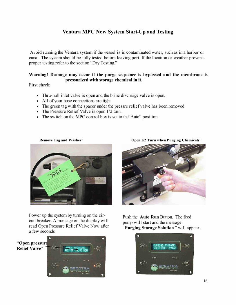
Warning! Damage may occur if the purge sequence is bypassed and the membrane is
pressurized with storage chemical in it.
Thru-hull inlet valve is open and the brine discharge valve is open.
All of your hose connections are tight.
The green tag with the spacer under the pressre relief valve has been removed.
The Pressure Relief Valve is open 1/2 turn.
The switch on the MPC control box is set to the“Auto” position.
First check:
Ventura MPC New System Start-Up and Testing
Open 1/2 Turn when Purging Chemicals! Remove Tag and Washer!
Power up the system by turning on the cir-
cuit breaker. A message on the display will
read Open Pressure Relief Valve Now after
a few seconds
Push the Auto Run Button. The feed
pump will start and the message
“Purging Storage Solution ” will appear.
“Open pressure
Relief Valve”
17
3. The system is now operational. You may start and run your system as you desire. You will
not have to go through the purging mode unless you “de -power” the system for more than 5
days. If you do, you can bypass the purge mode by pushing Stop and Auto Run buttons
simultaneously. When beginning to make water it is best to use the Auto Run button which
defaults to the automatic fresh water rinse after the unit is finished making water. If you
shut down the system by pressing the Stop button then use the Auto Store button to effect a
fresh water flush cycle.
Note: You can bypass the purge sequence and initiate a normal start at any time by
Pressing “Auto Run” and “Stop” simultaneously. This will bypass the purge se-
quence and enable a normal start.
If you must stop the purge sequence for any reason, the control will default back
to the beginning of the purging mode to protect your system.
Do not bypass the purge mode unless you are sure that the chemicals are purged
from the system or you will permanently damage the membrane.
1. After the purge sequence, the control will alarm with the message “ Close pressure relief
valve”. Close the valve and proceed by pressing Auto Run.
2. The system is now running under pressure and making water. The display will read
“purging product water.” This mode dumps the product water overboard for ten minutes
in case there is any residual chemicals in the membrane. Carefully inspect for leaks over the
entire system! Shut down the system and repair any leaks you find.
4. Check that the system is operating within its normal parameters. Compare with the chart on
the next page.
The system will go into a “starting mode” and the feed pump will start shortly after. The system
should prime within 60-90 seconds. Check the strainer and the brine discharge for water flow.
There should be few bubbles anywhere in the intake hoses and the feed pump should sound
smooth after priming. After confirming that the system is primed, inspect for leaks.
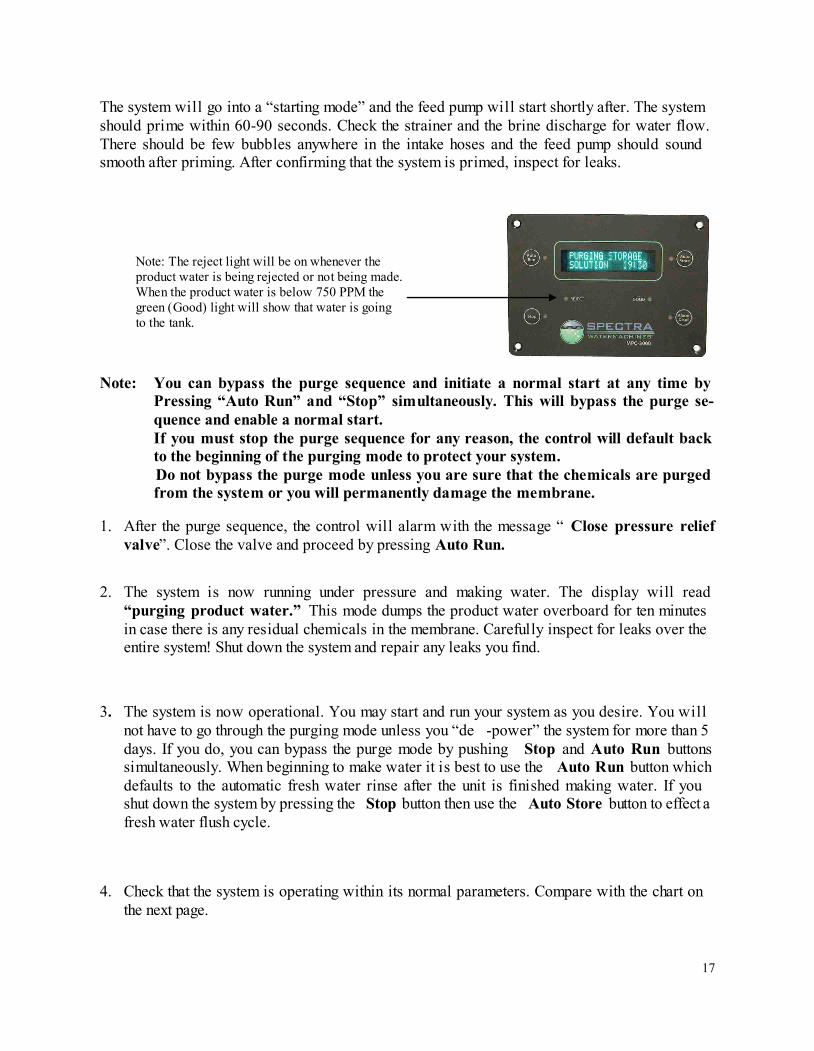
Note: The reject light will be on whenever the
product water is being rejected or not being made.
When the product water is below 750 PPM the
green (Good) light will show that water is going
to the tank.
18
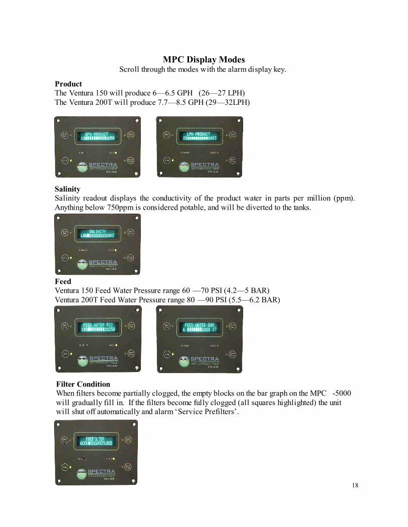
Product
The Ventura 150 will produce 6—6.5 GPH (26—27 LPH)
The Ventura 200T will produce 7.7—8.5 GPH (29—32LPH)
MPC Display Modes
Scroll through the modes with the alarm display key.
Salinity
Salinity readout displays the conductivity of the product water in parts per million (ppm).
Anything below 750ppm is considered potable, and will be diverted to the tanks.
Feed
Ventura 150 Feed Water Pressure range 60 —70 PSI (4.2—5 BAR)
Ventura 200T Feed Water Pressure range 80 —90 PSI (5.5—6.2 BAR)
Filter Condition
When filters become partially clogged, the empty blocks on the bar graph on the MPC -5000
will gradually fill in. If the filters become fully clogged (all squares highlighted) the unit
will shut off automatically and alarm ‘Service Prefilters’.
19
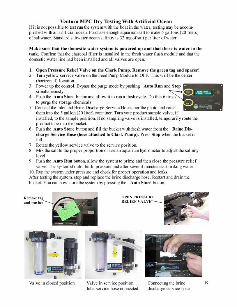
Ventura MPC Dry Testing With Artificial Ocean
If it is not possible to test run the system with the boat in the water, testing may be accom-
plished with an artificial ocean. Purchase enough aquarium salt to make 5 gallons (20 liters)
of saltwater. Standard saltwater ocean salinity is 32 mg of salt per liter of water.
Make sure that the domestic water system is powered up and that there is water in the
tank. Confirm that the charcoal filter is installed in the fresh water flush module and that the
domestic water line had been installed and all valves are open.
1. Open Pressure Relief Valve on the Clark Pump. Remove the green tag and spacer!
2. Turn yellow service valve on the Feed Pump Module to OFF. This will be the center
(horizontal) location.
3. Power up the control. Bypass the purge mode by pushing Auto Run and Stop
simultaneously.
4. Push the Auto Store button and allow it to run a flush cycle. Do this 6 times
to purge the storage chemicals.
5. Connect the Inlet and Brine Discharge Service Hoses per the photo and route
them into the 5 gallon (20 liter) container. Turn your product sample valve, if
installed, to the sample position. If no sampling valve is installed, temporarily route the
product tube into the bucket.
6. Push the Auto Store button and fill the bucket with fresh water from the Brine Dis-
charge Service Hose (hose attached to Clark Pump). Press Stop when the bucket is
full.
7. Rotate the yellow service valve to the service position.
8. Mix the salt to the proper proportion or use an aquarium hydrometer to adjust the salinity
level.
9. Push the Auto Run button, allow the system to prime and then close the pressure relief
valve. The system should build pressure and after several minutes start making water.
10. Run the system under pressure and check for proper operation and leaks.
After testing the system, stop and replace the brine discharge hose. Restart and drain the
bucket. You can now store the system by pressing the Auto Store button.
Valve in closed position
Valve in service position
Inlet service hose connected
Connecting the brine
discharge service hose
Remove tag
and washer
OPEN PRESSURE
RELIEF VALVE
20
Automatic Store Cycle
Warning! Proper understanding of the Spectra flush system and the vessel’s fresh water system
configuration is mandatory for extended Auto Store. The flush cycles must not be allowed to
drain all the fresh water from the vessel or damage to the vessel’s systems and the watermaker
may occur.
Make sure there is enough water in the fresh water tanks to supply the watermaker for more
than the expected time of operation in the “Auto Store” mode. The Ventura requires about 3
–3.5 gallons (11—13 liters) every 5 days.
Make sure the boat’s pressure water supply is on and will stay on during the flush mode (If
this is not possible contact your certified dealer.)
Make sure that the Pressure Relief Valve on the Clark Pump is closed.
The system must continually be powered during the Auto Store Mode. Turning off the
power will disable the five day automatic fresh water flush and damage may occur.
Pressing the Auto Store button once will start a flush and then activate the 5 day
flush cycle. The feed pump will start, the flush water solenoid will open and the display will
read “FRESH WATER FLUSH” with a countdown timer. After 3 minutes the pump will
stop, the display will read “FLUSH TIMER INTERVAL,” and the countdown timer will
reflect the number of hours until the next flush.
Pressing and holding the Auto Store button for 5 seconds will engage a one
time flush. The system flushes as described above but will not re -flush every 5 days. Dis-
play will read “FRESH WATER FLUSH” with a countdown timer, then the default display
will appear when finished.
Pressing the Stop button will cancel the Auto Store Mode.
Flush Cycle Adjustment
Before shipping from the factory the Ventura watermaker flush cycle is set to factory default
settings. After initial start up, and annually thereafter, the flush cycle parameters must be ad-
justed to ensure that the salt water is thoroughly flushed out of the machine while using the least
amount of fresh water possible.
If the fresh water supply is insufficient, seawater is drawn in to make up the difference and the
system is not flushed with completely fresh water. After checking for adequate flush water
flow, check the “Flush Duration” using Programming Function from the MPC display. Set the
Flush Duration so that the Fresh Water Flush comes to an end just as the salinity of the brine
discharge drops below 1000 ppm, or no longer tastes brackish. (Further instructions about how
to access the Programming Function can be found in part two of this manual)
21
Ventura MPC Operation
Normal operation
If the system has been pickled or stored, use the “New System Startup” procedure.
1. Check to see that the inlet seacock is open.
2. Push the Auto Run one or more times. The machine will run for one hour for each time
the button is pushed, then shut off and automatically do a fresh water flush. If you receive
a “System Stalled” error code, there is no water flow through the system. Open the pressure
relief valve on the Clark Pump and bleed the air out of the feed pump.
3. Run the system until you have filled your tank or have made enough to meet your require-
ments for several days.
4. When the unit shuts down it will enter the “Auto Store” mode, which will flush the unit
every five days unless you run it to make water, the unit is de -powered, or the Stop button
is pressed.
5. You may stop the system at any time with the Stop button. If the Stop button is pressed
during operation, the system will not flush itself or go into “Auto Flush” mode.
Remember that you need to run the system almost a half hour to make enough flushing water.
You may notice that the system output is higher when charging your batteries this is because
the watermaker is voltage sensitive.
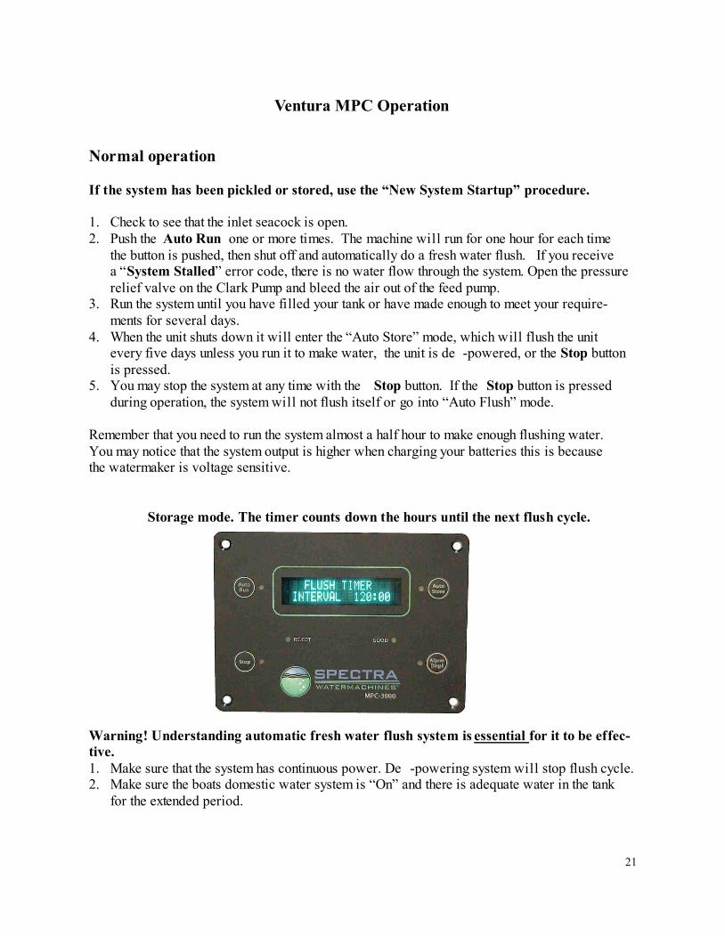
Storage mode. The timer counts down the hours until the next flush cycle.
Warning! Understanding automatic fresh water flush system is essential for it to be effec-
tive.
1. Make sure that the system has continuous power. De -powering system will stop flush cycle.
2. Make sure the boats domestic water system is “On” and there is adequate water in the tank
for the extended period.
22
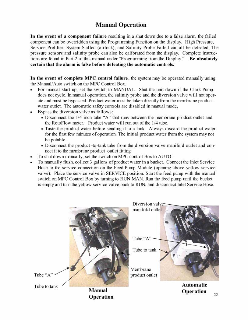
In the event of complete MPC control failure , the system may be operated manually using
the Manual/Auto switch on the MPC Control Box.
For manual start up, set the switch to MANUAL. Shut the unit down if the Clark Pump
does not cycle. In manual operation, the salinity probe and the diversion valve will not oper-
ate and must be bypassed. Product water must be taken directly from the membrane product
water outlet. The automatic safety controls are disabled in manual mode.
Bypass the diversion valve as follows:
Disconnect the 1/4 inch tube “A” that runs between the membrane product outlet and
the RotoFlow meter. Product water will run out of the 1/4 tube.
Taste the product water before sending it to a tank. Always discard the product water
for the first few minutes of operation. The initial product water from the system may not
be potable.
Disconnect the product -to-tank tube from the diversion valve manifold outlet and con-
nect it to the membrane product outlet fitting.
To shut down manually, set the switch on MPC control Box to AUTO .
To manually flush, collect 3 gallons of product water in a bucket. Connect the Inlet Service
Hose to the service connection on the Feed Pump Module (opening above yellow service
valve). Place the service valve in SERVICE position. Start the feed pump with the manual
switch on MPC Control Box by turning to RUN MAN. Run the feed pump until the bucket
is empty and turn the yellow service valve back to RUN, and disconnect Inlet Service Hose.
Manual Operation
Tube “A”
Tube to tank
Membrane
product outlet
Automatic
Operation
Manual
Operation
Tube “A”
Tube to tank
Diversion valve
manifold outlet
In the event of a component failure resulting in a shut down due to a false alarm, the failed
component can be overridden using the Programming Function on the display. High Pressure,
Service Prefilter, System Stalled (airlock), and Salinity Probe Failed can all be defeated. The
pressure sensors and salinity probe can also be calibrated from the display. Complete instruc-
tions are found in Part 2 of this manual under “Programming from the Display.” Be absolutely
certain that the alarm is false before defeating the automatic controls.
23
Long Term Storage Procedures
Watermakers are best when run continuously. When not in use, biological growth in the
membrane is the leading cause of membrane fouling. A warm environment will cause more
growth than a cold environment. A Fresh Water Flush every five days will greatly reduce
biological growth but may not stop it completely. You can also protect you watermaker
with the optional Z -Brane water treatment system. These systems protect the membrane
from bio-fouling with out the use of storage chemicals.
System Storage or “Pickling”
If the system is to be left unused for more than five days, perform the following storage pro-
cedure.
A system can be stored for up to six months with SC -1 Storage Compound.
The procedure introduces a chemical compound into the system that prevents biological
growth. This procedure requires de-chlorinated water which can be made with the charcoal
filter. Charcoal filters last a maximum of 6 months once wetted.
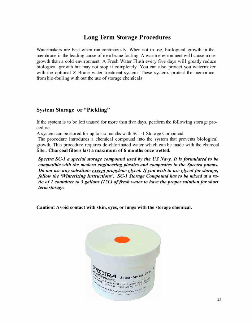
Spectra SC-1 a special storage compound used by the US Navy. It is formulated to be
compatible with the modern engineering plastics and composites in the Spectra pumps.
Do not use any substitute except propylene glycol. If you wish to use glycol for storage,
follow the ‘Winterizing Instructions’. SC-1 Storage Compound has to be mixed at a ra-
tio of 1 container to 3 gallons (12L) of fresh water to have the proper solution for short
term storage.
Caution! Avoid contact with skin, eyes, or lungs with the storage chemical.
24
Ventura MPC Storage Procedure
1. Turn the yellow service valve on the Feed Pump Module to OFF (horizontal position)
2. Perform two fresh water flushes by pushing the Auto Store button .
3. Remove the cap on the service port on the Feed Pump Module and install the Inlet Ser-
vice Hose from the service kit. Remove the quick disconnect fitting from the brine dis-
charge outlet of the Clark Pump, and replace with a quick disconnect Brine Discharge
Service Hose. Lead the both hoses to a 5 gallon bucket or container.
4. Push the Auto Store button and run the feed pump until you have one gallon of fresh
water in the bucket. Stop the system. Fresh Water should enter the bucket from the
Brine Discharge Service Hose.
5. Mix 1 container of SC-1 storage compound with the water in the bucket.
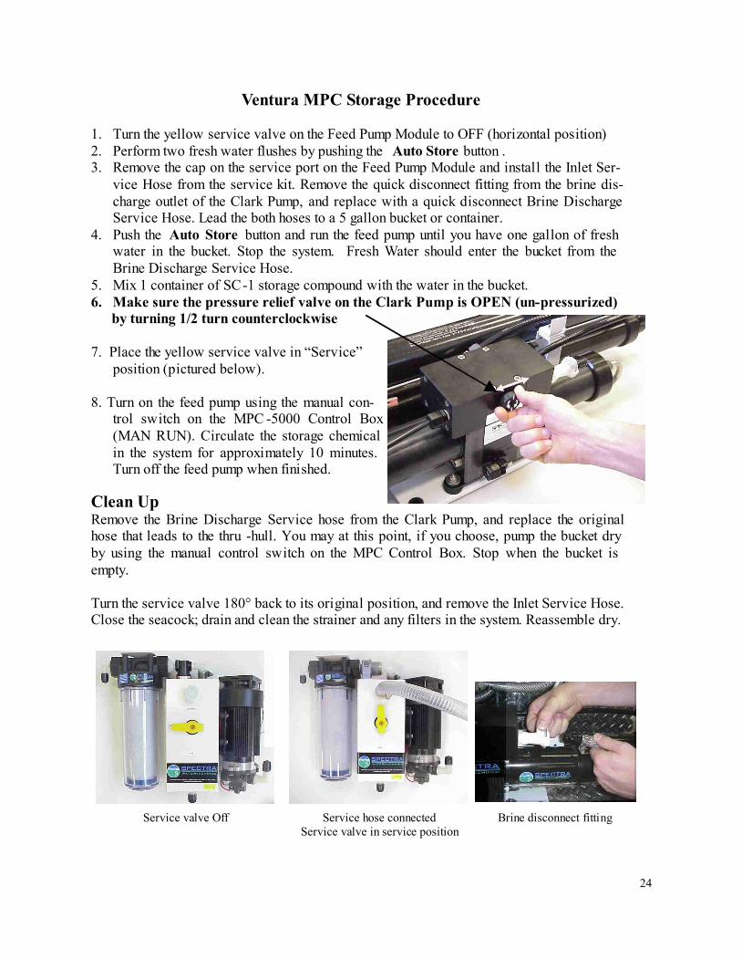
6. Make sure the pressure relief valve on the Clark Pump is OPEN (un-pressurized)
by turning 1/2 turn counterclockwise
7. Place the yellow service valve in “Service”
position (pictured below).
8. Turn on the feed pump using the manual con-
trol switch on the MPC -5000 Control Box
(MAN RUN). Circulate the storage chemical
in the system for approximately 10 minutes.
Turn off the feed pump when finished.
Clean Up
Remove the Brine Discharge Service hose from the Clark Pump, and replace the original
hose that leads to the thru -hull. You may at this point, if you choose, pump the bucket dry
by using the manual control switch on the MPC Control Box. Stop when the bucket is
empty.
Turn the service valve 180° back to its original position, and remove the Inlet Service Hose.
Close the seacock; drain and clean the strainer and any filters in the system. Reassemble dry.
Service valve Off Service hose connected
Service valve in service position
Brine disconnect fitting
25
Winterizing
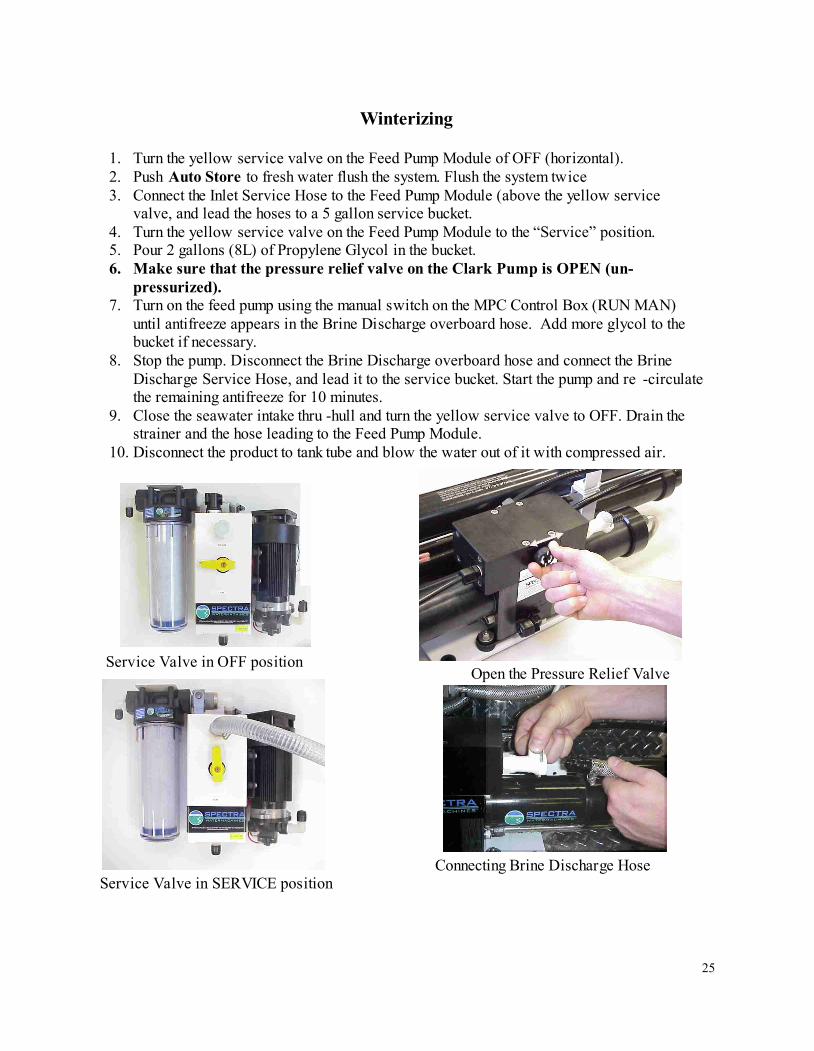
1. Turn the yellow service valve on the Feed Pump Module of OFF (horizontal).
2. Push Auto Store to fresh water flush the system. Flush the system twice
3. Connect the Inlet Service Hose to the Feed Pump Module (above the yellow service
valve, and lead the hoses to a 5 gallon service bucket.
4. Turn the yellow service valve on the Feed Pump Module to the “Service” position.
5. Pour 2 gallons (8L) of Propylene Glycol in the bucket.
6. Make sure that the pressure relief valve on the Clark Pump is OPEN (un-
pressurized).
7. Turn on the feed pump using the manual switch on the MPC Control Box (RUN MAN)
until antifreeze appears in the Brine Discharge overboard hose. Add more glycol to the
bucket if necessary.
8. Stop the pump. Disconnect the Brine Discharge overboard hose and connect the Brine
Discharge Service Hose, and lead it to the service bucket. Start the pump and re -circulate
the remaining antifreeze for 10 minutes.
9. Close the seawater intake thru -hull and turn the yellow service valve to OFF. Drain the
strainer and the hose leading to the Feed Pump Module.
10. Disconnect the product to tank tube and blow the water out of it with compressed air.
Service Valve in SERVICE position
Connecting Brine Discharge Hose
Service Valve in OFF position
Open the Pressure Relief Valve
26
Maintenance
The Seawater Strainer
The seawater strainer’s stainless steel element should be inspected, removed, and cleaned as
needed. Be careful to ensure that the thru -hull is closed before disassembly and the gasket is
in place before reassembly. When the system is put into storage, remove, rinse, and reassem-
ble dry to impede corrosion. Check frequently during operation.
The Prefilters
Service the pre-filters on a regular basis. The MPC will alarm when the filters reach a 10
PSI (.7 BAR) pressure drop. If you use the system until it stops at a 10 PSI differential (.75
BAR) then the filters will have to be discarded.
To service the filters, turn the yellow service valve to OFF, open the filter housing, and dis-
card the old filters. Clean out the housing bowl then reassemble the housings with new 5
and 20 micron filter elements. Leave dry until next startup.
Use only Spectra approved filters or you may void your warranty. The filters may be GEN-
TLY cleaned up to 3 times with a soft brush and water in a bucket. Occasionally, lightly
lube the filter housing O -ring with silicone grease.
Replace the charcoal filter element at least every 6 months ! This filter protects the
membrane by removing chlorine from the fresh flush water. Use only a Spectra replace-
ment!
Oil Water Separator (Optional)
To install oil water separator capability, remove the 20 micron filter from the dual filter housing
and replace with the oil water separator element. Service as you would per the instructions
above.
General
Periodically inspect the entire system for leakage and chafe on the tubing and hoses. Repair
any leaks you find as soon as practical. Some crystal formation around the Clark Pump
blocks is normal. Wipe down any salt encrusted areas with a damp cloth.
The Charcoal Fresh Water Flush Filter
The Feed Pump and Clark Pump
The feed pump and the Clark Pump require no routine maintenance except inspection for
leaks. Tighten any hose clamps or fittings the show signs of leakage. The high pressure
stainless steel fittings threaded into the Clark Pump have o -ring seals with a straight thread.
These should never leak and should never be over tightened. If one of the tube nuts starts to
leak it can be un -threaded, sealed with a bit of silicone grease or silicone seal, and, using two
wrenches, tightened very tight.
27
If known bio-fouling is present, the SC-2 may be used first.
If the history of the system is unknown or has been left “unpickled” for an extended length of
time and biological growth is present, consider cleaning with SC-2. Use dechlorinated fresh wa-
ter and do not pressurize the system (leave the pressure relief valve slightly open when clean-
ing).
De-chlorinated fresh water can be obtained by running water through your Spectra charcoal fil-
ter.
Test to see if biological growth has occurred.
Before running the system, remove the prefilters and examine their condition. If the filter hous-
ings are full of smelly discolored water, the system was not properly stored. Install clean pre-
filters.
Next check the membrane. Detach the brine discharge hose and lead to a bucket. Open the pres-
sure relief valve one turn, and manually run the system for 30 seconds (metal toggle switch on
Feed Pump Module). Examine the brine water: if it is discolored and smells bad, perform an
SC-2 cleaning with unchlorinated water before running the system pressurized. If the brine is
fairly clean, follow the “new start up procedure” and run normally. Check for performance.
Clean the membranes only if performance is reduced.
Warm water is ideal for cleaning membranes. One way to do this is to find a camp stove and
use a large stainless steel pot to heat the solution to 120° F (48 C), you might have to
periodically stop and reheat the solution.
Perform the cleaning procedures while the ship is in acceptable sea water for purging and testing .
Always perform a flow test before cleaning your membrane. Cleaning shortens the lifespan
of membranes so only clean after you have investigated all other potential causes. The lead-
ing cause of fouling is from biological growth that occurs when the system is left unused
without flushing or pickling. Fouling from mineral scaling can happen during operation un-
der certain seawater conditions and from rust. Monitor the product salinity and feed pres-
sure for higher than normal readings, take environmental conditions into consideration.
Cold feed water or clogged filters can cause high pressure.
Low product flow is usually due to low voltage, or a worn Feed Pump / Clark Pump. Look
for all other causes before cleaning the membrane. Membrane life can be shortened by ex-
cessive cleaning.
There are two types of cleaners: acid and alkaline.
The acid cleaner (SC-3) will remove mineral scaling and is generally used first.
The alkaline cleaner (SC-2) is used to remove biological by-products, oil, and dirt particles
that get past the prefilters.
If membrane performance is reduced and the system has not been pickled recently, cleaning
with both chemicals is recommended. The acid cleaner should be used first. If the membrane
fails to respond to both cleanings, this is an indication of another problem with the system, or
that it is time to replace the membrane. Contact Spectra Watermakers before removing a mem-
brane.
The Membranes
28
Please Perform a FLOW TEST before you clean your membrane. The change in production
is normally caused by something other then the membrane unless the system has been left un-
used for long periods of time. Excessive cleaning can damage your membrane.
HS LF-2 FLOW TEST/ SHURFLO
Before the test, change all filters and clean the strainer. Make sure that there are no leaks.
Check for air leaks, as air in the system will cause low production and erratic salinity. Look for
air bubbles in the product flow meter, feed water hoses, and brine overboard hose.
Run the system and watch the pressures very closely. Make sure that on each shift everything
is even from side to side. If the feed pressure or time between shifts of the Clark Pump is dif-
ferent (asymmetrical) on one stroke from the other, this could be part of the problem. A differ-
ence of a few PSI is acceptable, but anything over that is an issue. If the pump is asymmetrical,
Clark Pump repairs should be done before continuing with these tests. Ask for “ CP-5 Clark
Pump Checkout ” instructions.
If no asymmetry is noted, continue with this test.
NOTE:
Make sure the ShurFlo overpressure cutout switches (p/n PL -PMP-SFPH), are set to 125 psi.
With pump running, close the brine service valve. The feed pressure should rise to 125 psi and
the pump should shut off. If the pumps shut off at a lower pressure see “ SF-2 Adjust ShurFlo
Pressure Switch” bulletin.
1. Measure and log the product flow GPM (LPM) and the feed pressure with pump pumps run-
ning. Use a graduated container and timer to measure the flow. Log the voltage at the feed
pumps at the same time. Confirm at least 12.5 or 24.5 volts at the pump. You may have to
run the engine or battery charger during the test.
2. Measure the total flow rate of the system. Run the system making water and divert BOTH
the brine discharge AND product water into a bucket. Time how long it takes to make a
given amount of water.
In order to make good water, you need the proper amount of feed water flow. Each pump alone
should produce 1.5 gallons per minute (5.7 lpm).
Compare the product flow to the total feed flow. Product flow should be 9.5% of total flow for
a 200 model. If product percentage is low, you may have an internal leak in the Clark Pump.
For every
1
/
10
th
of a gpm feed water flow loss, we will lose about
1
/
2
gallon per hour of product
flow and the salinity will go up 100ppm.
Low feed flow combined with low system pressures (see Misc-4: Nominal Pressures) is most
frequently due to worn ShurFlo pump heads (p/n PL -PMP-SFPH).
29
CLEANING CHEMICALS 101
Spectra Systems use four types of chemicals: SC-1, SC-2, SC-3, and propylene glycol
antifreeze.
NOTE: Never use any chemicals with the system pressurized! Always open the pressure
relief valve on Clark Pump
1
/
2
turn. Always purge a system containing chemicals for at least 20
minutes unpressurized before pressurizing (closing the pressure relief valve) and making water.
CLEANERS: Cleaning can shorten a membrane’s life. Avoid unnecessary cleaning. Avoid
cleaning as a diagnostic tool.
PROCEDURE: Cleaning solutions are most effective if heated to 120
o
F. On a boat, this is not
easy to do. We recommend circulating the solution through a metal pot on the stove, or
consistently taking a scoop out of the cleaning bucket – warming scoop of cleaning mixture on
the stove - then pouring scoop back into the cleaning bucket.
If you cannot heat the solution, circulate the cleaning solution for several hours and then let
solution sit in the watermaker over night.
In most cases the water quality will increase in PPM after an SC-2 cleaning. It might take
several hours for your system to return to normal production.
SC-3 is an acid cleaner used to remove mineral and scale deposits. This is used in the same
way as the SC-2. In most cases SC-3 is used first, and if no results are achieved, proceed with
the SC-2. SC-3 cleaning should lower the product PPM and over all pressures. Scaling is a slow
process that may take several months or years. SC -3 is less harmful to the membrane then SC -2
and will almost always improve the performance of an older membrane.
SC-2 is an alkaline cleaner used to remove light oil, grime , and biological growth. If you have
cleaned your filters, filter housing, and fresh water flushed your system several times and the
product water continues to smell consider using SC -2.
30
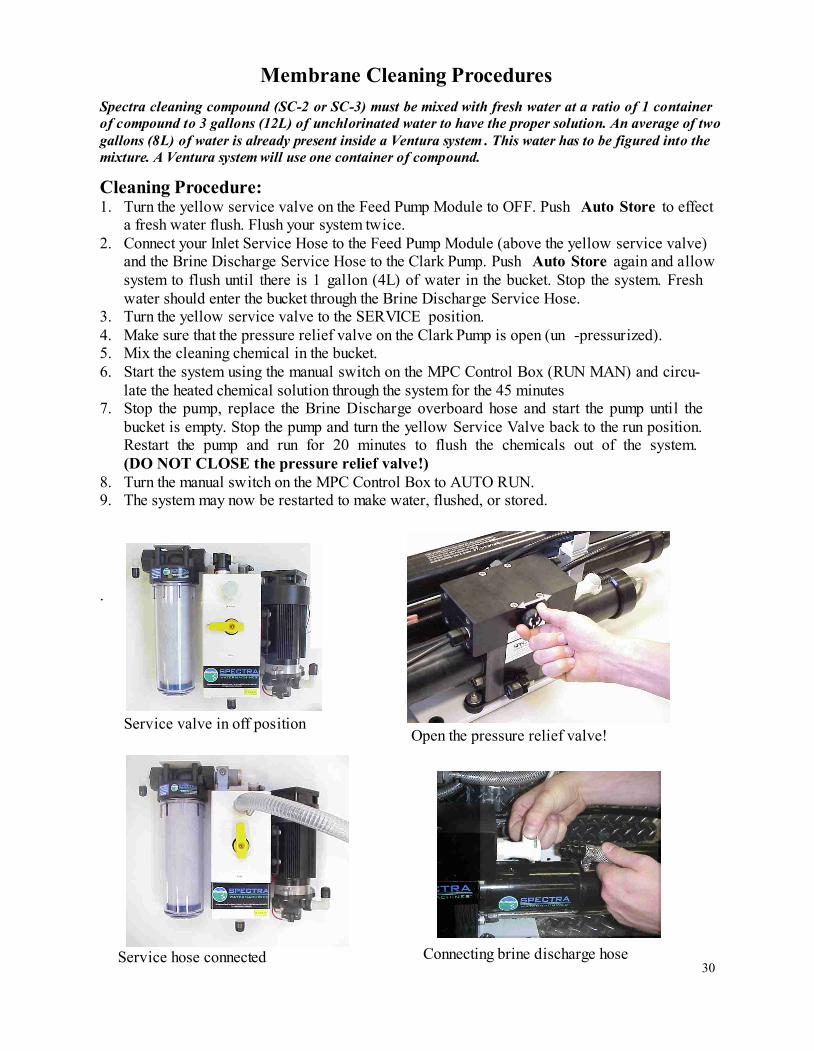
Cleaning Procedure:
1. Turn the yellow service valve on the Feed Pump Module to OFF. Push Auto Store to effect
a fresh water flush. Flush your system twice.
2. Connect your Inlet Service Hose to the Feed Pump Module (above the yellow service valve)
and the Brine Discharge Service Hose to the Clark Pump. Push Auto Store again and allow
system to flush until there is 1 gallon (4L) of water in the bucket. Stop the system. Fresh
water should enter the bucket through the Brine Discharge Service Hose.
3. Turn the yellow service valve to the SERVICE position.
4. Make sure that the pressure relief valve on the Clark Pump is open (un -pressurized).
5. Mix the cleaning chemical in the bucket.
6. Start the system using the manual switch on the MPC Control Box (RUN MAN) and circu-
late the heated chemical solution through the system for the 45 minutes
7. Stop the pump, replace the Brine Discharge overboard hose and start the pump until the
bucket is empty. Stop the pump and turn the yellow Service Valve back to the run position.
Restart the pump and run for 20 minutes to flush the chemicals out of the system.
(DO NOT CLOSE the pressure relief valve!)
8. Turn the manual switch on the MPC Control Box to AUTO RUN.
9. The system may now be restarted to make water, flushed, or stored.
.
Service valve in off position
Open the pressure relief valve!
Service hose connected
Connecting brine discharge hose
Spectra cleaning compound (SC-2 or SC-3) must be mixed with fresh water at a ratio of 1 container
of compound to 3 gallons (12L) of unchlorinated water to have the proper solution. An average of two
gallons (8L) of water is already present inside a Ventura system . This water has to be figured into the
mixture. A Ventura system will use one container of compound.
Membrane Cleaning Procedures
31
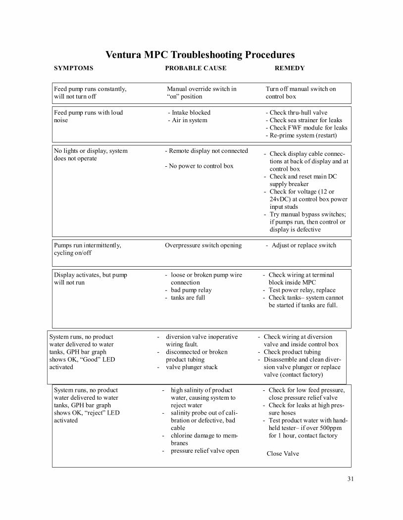
Feed pump runs constantly,
will not turn off
Manual override switch in
“on” position
Turn off manual switch on
control box
SYMPTOMS PROBABLE CAUSE REMEDY
Ventura MPC Troubleshooting Procedures
No lights or display, system
does not operate
- Remote display not connected
- No power to control box
- Check display cable connec-
tions at back of display and at
control box
- Check and reset main DC
supply breaker
- Check for voltage (12 or
24vDC) at control box power
input studs
- Try manual bypass switches;
if pumps run, then control or
display is defective
Feed pump runs with loud
noise
- Intake blocked
- Air in system
- Check thru-hull valve
- Check sea strainer for leaks
- Check FWF module for leaks
- Re-prime system (restart)
Pumps run intermittently,
cycling on/off
Overpressure switch opening - Adjust or replace switch
Display activates, but pump
will not run
- loose or broken pump wire
connection
- bad pump relay
- tanks are full
- Check wiring at terminal
block inside MPC
- Test power relay, replace
- Check tanks– system cannot
be started if tanks are full.
System runs, no product
water delivered to water
tanks, GPH bar graph
shows OK, “Good” LED
activated
- diversion valve inoperative
wiring fault.
- disconnected or broken
product tubing
- valve plunger stuck
- Check wiring at diversion
valve and inside control box
- Check product tubing
- Disassemble and clean diver-
sion valve plunger or replace
valve (contact factory)
System runs, no product
water delivered to water
tanks, GPH bar graph
shows OK, “reject” LED
activated
- high salinity of product
water, causing system to
reject water
- salinity probe out of cali-
bration or defective, bad
cable
- chlorine damage to mem-
branes
- pressure relief valve open
- Check for low feed pressure,
close pressure relief valve
- Check for leaks at high pres-
sure hoses
- Test product water with hand-
held tester– if over 500ppm
for 1 hour, contact factory
Close Valve
32
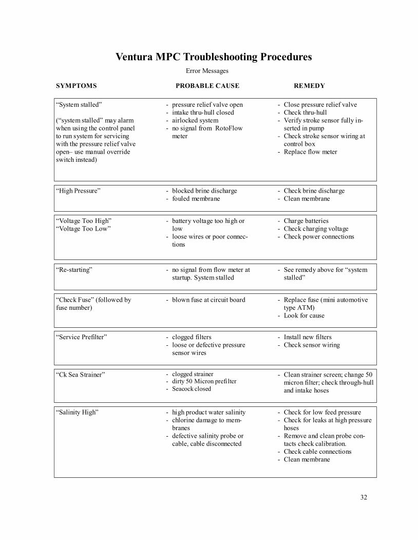
SYMPTOMS PROBABLE CAUSE REMEDY
Ventura MPC Troubleshooting Procedures
Error Messages
“System stalled”
(“system stalled” may alarm
when using the control panel
to run system for servicing
with the pressure relief valve
open– use manual override
switch instead)
- pressure relief valve open
- intake thru-hull closed
- airlocked system
- no signal from RotoFlow
meter
- Close pressure relief valve
- Check thru-hull
- Verify stroke sensor fully in-
serted in pump
- Check stroke sensor wiring at
control box
- Replace flow meter
“High Pressure” - blocked brine discharge
- fouled membrane
- Check brine discharge
- Clean membrane
“Voltage Too High”
“Voltage Too Low”
- battery voltage too high or
low
- loose wires or poor connec-
tions
- Charge batteries
- Check charging voltage
- Check power connections
“Re-starting” - no signal from flow meter at
startup. System stalled
- See remedy above for “system
stalled”
“Check Fuse” (followed by
fuse number)
- blown fuse at circuit board - Replace fuse (mini automotive
type ATM)
- Look for cause
“Service Prefilter” - clogged filters
- loose or defective pressure
sensor wires
- Install new filters
- Check sensor wiring
“Ck Sea Strainer”
- clogged strainer
- dirty 50 Micron prefilter
- Seacock closed
- Clean strainer screen; change 50
micron filter; check through-hull
and intake hoses
“Salinity High” - high product water salinity
- chlorine damage to mem-
branes
- defective salinity probe or
cable, cable disconnected
- Check for low feed pressure
- Check for leaks at high pressure
hoses
- Remove and clean probe con-
tacts check calibration.
- Check cable connections
- Clean membrane
33
ACCUMULATOR PRESSURE
All Spectra Watermakers, except the Newport 700 and 1000 series, are supplied with a pressure
accumulator tank (part no. PL -ACC-TK) to be installed in the feed water line between the pre-
filters and the Clark Pump.
The purpose of the feed line accumulator is to reduce the spikes in the feed pressure caused by
the shifting of the Clark pump. If the accumulator is not properly charged it can lead to prob-
lems with the ShurFlo Feed Pump pressure cutout switches. The accumulators have an air
valve on top similar to those found on car/ bike tires. This allows the internal air bladder of the
accumulator to be precharged. The accumulator should be pumped up to about 60psi (4.5bar)
for best results. Add air using a tire pump or air compressor. You can experiment with the ex-
act pressure that will give the best pulsation dampening on your installation.
The purpose of the fresh water flush accumulator is to allow a steady flow of 1.5 gallons per
minute of flush water through the charcoal filter. The accumulator gives the water flowing
through the charcoal filter somewhere to go while the feed pump is cycled off. The flush water
accumulator should be preloaded to 5 psi (.35bar).
34
OP-4 FRESH WATER FLUSH
The purpose of the fresh water flush is to replace the seawater in the watermaker with fresh wa-
ter whenever the system is producing water. The “Auto Flush Mode” on the MPC 5000
changes the fresh water every five days that the system sits idle. The watermaker will last
longer and operate better if it is always kept filled with fresh water between uses.
Most spectra watermakers are equipped with a Auto Store, automatic fresh water flush mode.
This module includes a charcoal filter to remove any chlorine in the fresh water that might dam-
age the membrane, and an electrically operated valve. The electrically operated solenoid valve
opens during the fresh water flush allowing the boats pressurized water system to supply water
to the system.
If the ship’s water system is unable to provide flush water at the required flow rate, sea water
will be drawn in to make up the difference. This will cause the flush water to be brackish, and
ineffective in preserving the watermaker. At initial startup the fresh water flush system should
be tested by taking a sample of the brine discharge water just as the flush cycle is ending. This
water should not taste salty, and should read less than 1000 ppm on a digital tds meter.
Because the pre -filters trap the plankton in the feed water they can be subject to “going anaero-
bic” or starting to smell like rotten eggs, as the trapped plankton decay. For this reason it is ad-
visable to always put in clean filters if the unit is going to be left on Auto Flush Mode. In daily
or regular fresh water flush the watermaker after each shutdown will help prevent this problem,
but in excessively warm or fertile waters the pre-filters will need regular attention.

35
SF-1 SHURFLO PUMP WON’T RUN
If the feed pump has power to it (the fan runs), but the pump won’t run, the first thing to check
is the pressure switch. The pressure switch, (part number: EL -FP-PS), is located on the wet
end of the pump and has two red wires plugged into it. Jump the two red wires together and
see if the pump runs. You can safely run the system with the pressure switch jumped, just
keep an eye on the pressure gauge and don’t let system pressure exceed 110 psi. Replace the
switch when a spare is available.
If the pump will not run with the pressure switch jumped then it is most likely a problem with
the brushes or overheat protection switch inside the motor. The motor will come completely
apart by removing the two screws on the end of the motor. Remove the rear cover and paper
insulator. Pull out the plastic brush holder. The thermal switch is located on one of the brush
leads. With an ohmmeter, check for continuity through the switch. If it is open, you can
make temporary repairs by wiring around it, being careful that your new wiring doesn’t chafe
on the moving parts, nor resist the springs that push the brushes on to the commutator.
If any corrosion is apparent the brushes may be sticking. Once apart clean all the carbon dust
from all the parts. Clean the commutator with light sand paper. Make sure to clean the small
grooves on the commutator with a small sharp tool to remove the carbon in between the seg-
ments. Adjust the springs on the brush holders so the brushes slide smoothly in and out. If
the bearings are rough and binding, remove the rubber dust cover and clean the best you
can, grease them, and work it free by hand. Don't service the bearing unless absolutely neces-
sary. Reassemble in reverse order. You can hold the carbon brushes back with papers clips
inserted through the slots in the brush holder so they don't hang up on the bearing during as-
sembly. Make sure the corrugated bearing shim doesn't push out, if it does, push it back into
place.
This will at least keep you going until the motor can be replaced if necessary.
36
SF-2 ADJUST SHURFLO PRESSURE SWITCH
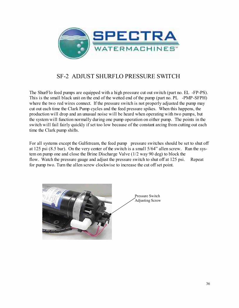
The ShurFlo feed pumps are equipped with a high pressure cut out switch (part no. EL -FP-PS).
This is the small black unit on the end of the wetted end of the pump (part no. PL -PMP-SFPH)
where the two red wires connect. If the pressure switch is not properly adjusted the pump may
cut out each time the Clark Pump cycles and the feed pressure spikes. When this happens, the
production will drop and an unusual noise will be heard when operating with two pumps, but
the system will function normally during one pump operation on either pump. The points in the
switch will fail fairly quickly if set too low because of the constant arcing from cutting out each
time the Clark pump shifts.
For all systems except the Gulfstream, the feed pump pressure switches should be set to shut off
at 125 psi (8.5 bar). On the very center of the switch is a small 5/64” allen screw. Run the sys-
tem on pump one and close the Brine Discharge Valve (1/2 way 90 deg) to block the
flow. Watch the pressure gauge and adjust the pressure switch to shut off at 125 psi. Repeat
for pump two. Turn the allen screw clockwise to increase the cut off set point.
Pressure Switch
Adjusting Screw
37
POOR PRODUCT QUALITY
With any product water quality issue, you need to check the calibration of the salinity tester
that you are using before proceeding.
Membranes are not an exact science and two identical systems can have a different product
quality result. World health standards deem water of up to 1000 PPM of total dissolved solids
acceptable for drinking consumption. We consider any thing below 750 PPM acceptable but
not ideal, and anything below 500 PPM excellent. Factors that could affect water quality are
addressed below.
LOW SYSTEM FLOW OR PRESSURE will equate to lower product quality (higher
PPM). Ventura systems, which have a higher feed to output pressure ratio (See MISC -
4 nominal pressures), as well as a higher feed flow/membrane area ratio, will produce
water in the 150-200 PPM range.
DAMAGE TO THE MEMBRANE by chlorine contamination. Flushing the system with
chlorinated water will irreparably damage the membrane. Charcoal filters are used to
absorb any chlorine which might be present in flush water. They must be of proper
specification to be suitable. There is no test for chlorine damage except the process of
elimination of other causes.
DIRTY OR SCALED membranes. A dirty (foreign material), scaled (mineral deposits), or
contaminated (bacterial growth) membrane can result in poor water quality and abnor-
mal operating pressures. If operating pressures are above normal, then cleaning is indi-
cated. If the system pressures are within operating normal range, cleaning may have
little result. Cleaning is no better for a membrane than it is for your clothes. Avoid
cleaning as a diagnostic tool.
MECHANICAL LEAKAGE within the membrane pressure vessel. This is an unlikely but
possible cause of poor water quality with old style Codeline pressure vessels (white)
that we have used in the past. The Spectra pressure vessel has a double O -ring arrange-
ment that includes a telltale hole between them so that any salt water leaking past an
O-ring will drip into the boat and not go into the product water.
If system flow (product plus brine) is 1.5 GPM or above on one pump, the membrane is clean,
the product flows are consistent with the system flow and the water quality is still not accept-
able, then replacement of the membrane is indicated. How to perform a Flow Test is de-
scribed right after the Membrane Maintenance section of your manual and also on the next
page.
38
Z-BRANE
OPERATION
MANUAL
Spectra Watermakers Inc.
20 Mariposa Rd., San Rafael, CA 94901
Phone 415-526-2780 Fax 415-526-2787
Email: [email protected]
Http://www.spectrawatermakers.com
Current manuals/Z-Brane 12/10/04
39
The Z-brane is a revolutionary product which applies Z-Guard High Voltage Capacitive tech-
nology to the Membrane Pressure Vessel. Always active, the Z -Brane creates an environment
that is unfriendly to bio -film and bacteria. The Z technology also assists in the prevention of
scale formation on the membrane surfaces. The Z -Brane allows the system to be shut down or
decommissioned for extended periods of time without chemicals or preservatives. The Z -Brane
will not prevent freezing. In cold climates Propylene Glycol is still required.
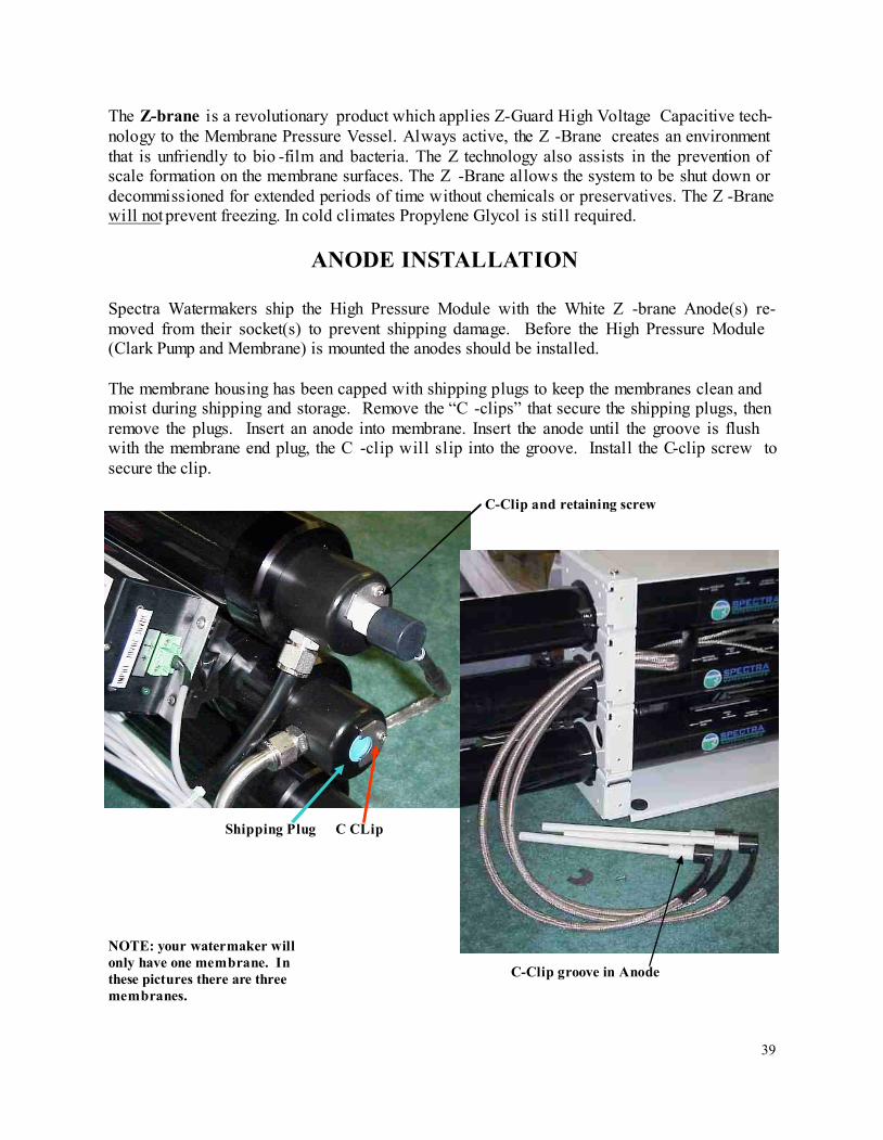
ANODE INSTALLATION
Spectra Watermakers ship the High Pressure Module with the White Z -brane Anode(s) re-
moved from their socket(s) to prevent shipping damage. Before the High Pressure Module
(Clark Pump and Membrane) is mounted the anodes should be installed.
The membrane housing has been capped with shipping plugs to keep the membranes clean and
moist during shipping and storage. Remove the “C -clips” that secure the shipping plugs, then
remove the plugs. Insert an anode into membrane. Insert the anode until the groove is flush
with the membrane end plug, the C -clip will slip into the groove. Install the C-clip screw to
secure the clip.
C-Clip and retaining screw
Shipping Plug
C-Clip groove in Anode
NOTE: your watermaker will
only have one membrane. In
these pictures there are three
membranes.
C CLip
40
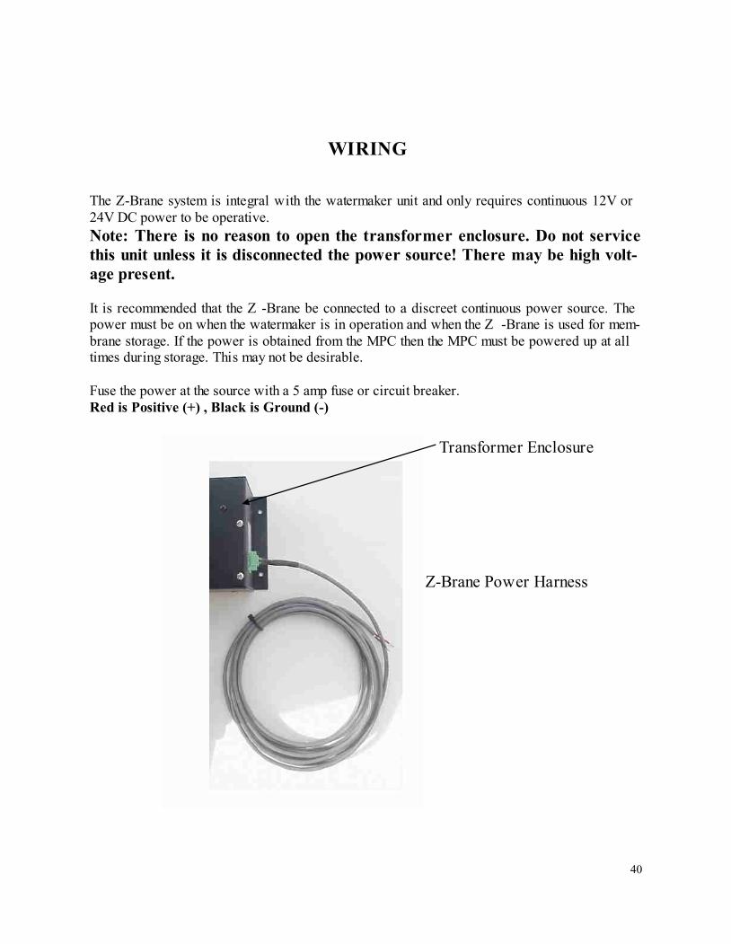
WIRING
The Z-Brane system is integral with the watermaker unit and only requires continuous 12V or
24V DC power to be operative.
Note: There is no reason to open the transformer enclosure. Do not service
this unit unless it is disconnected the power source! There may be high volt-
age present.
It is recommended that the Z -Brane be connected to a discreet continuous power source. The
power must be on when the watermaker is in operation and when the Z -Brane is used for mem-
brane storage. If the power is obtained from the MPC then the MPC must be powered up at all
times during storage. This may not be desirable.
Fuse the power at the source with a 5 amp fuse or circuit breaker.
Red is Positive (+) , Black is Ground (-)
Z-Brane Power Harness
Transformer Enclosure
41
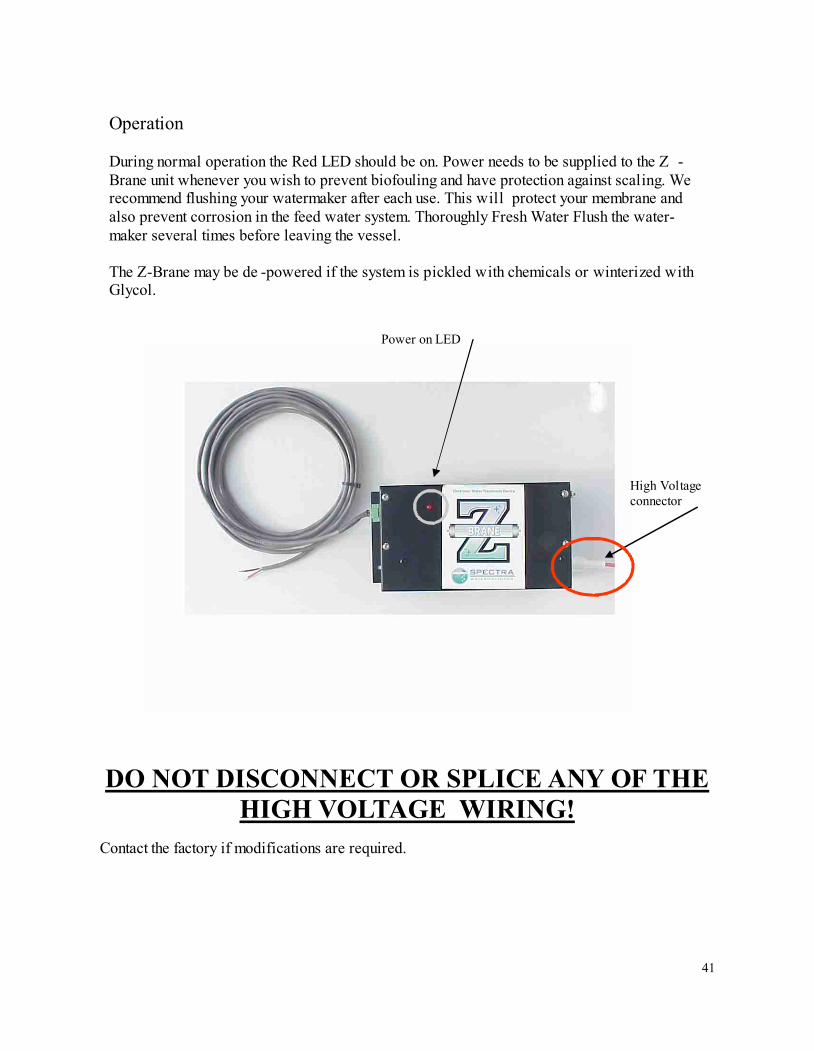
Operation
During normal operation the Red LED should be on. Power needs to be supplied to the Z -
Brane unit whenever you wish to prevent biofouling and have protection against scaling. We
recommend flushing your watermaker after each use. This will protect your membrane and
also prevent corrosion in the feed water system. Thoroughly Fresh Water Flush the water-
maker several times before leaving the vessel.
The Z-Brane may be de -powered if the system is pickled with chemicals or winterized with
Glycol.
DO NOT DISCONNECT OR SPLICE ANY OF THE
HIGH VOLTAGE WIRING!
Contact the factory if modifications are required.
Power on LED
High Voltage
connector
42
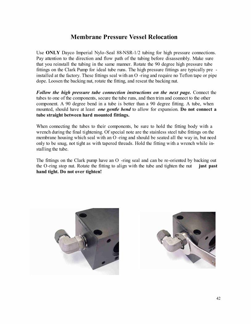
Membrane Pressure Vessel Relocation
Use ONLY Dayco Imperial Nylo-Seal 88-NSR-1/2 tubing for high pressure connections.
Pay attention to the direction and flow path of the tubing before disassembly. Make sure
that you reinstall the tubing in the same manner. Rotate the 90 degree high pressure tube
fittings on the Clark Pump for ideal tube runs. The high pressure fittings are typically pre -
installed at the factory. These fittings seal with an O -ring and require no Teflon tape or pipe
dope. Loosen the backing nut, rotate the fitting, and reseat the backing nut.
Follow the high pressure tube connection instructions on the next page. Connect the
tubes to one of the components, secure the tube runs, and then trim and connect to the other
component. A 90 degree bend in a tube is better than a 90 degree fitting. A tube, when
mounted, should have at least one gentle bend to allow for expansion. Do not connect a
tube straight between hard mounted fittings.
When connecting the tubes to their components, be sure to hold the fitting body with a
wrench during the final tightening. Of special note are the stainless steel tube fittings on the
membrane housing which seal with an O -ring and should be seated all the way in, but need
only to be snug, not tight as with tapered threads. Hold the fitting with a wrench while in-
stalling the tube.
The fittings on the Clark pump have an O -ring seal and can be re-oriented by backing out
the O-ring stop nut. Rotate the fitting to align with the tube and tighten the nut just past
hand tight. Do not over tighten!
43
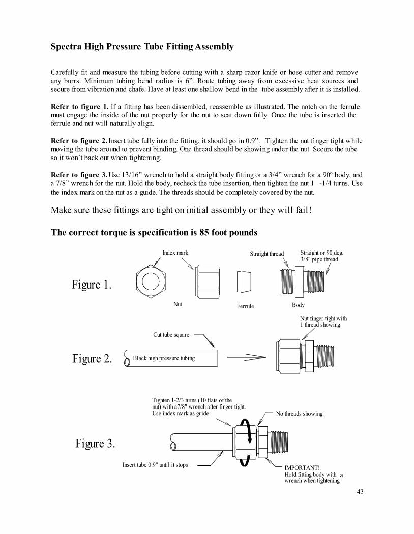
Spectra High Pressure Tube Fitting Assembly
Carefully fit and measure the tubing before cutting with a sharp razor knife or hose cutter and remove
any burrs. Minimum tubing bend radius is 6”. Route tubing away from excessive heat sources and
secure from vibration and chafe. Have at least one shallow bend in the tube assembly after it is installed.
Refer to figure 1. If a fitting has been dissembled, reassemble as illustrated. The notch on the ferrule
must engage the inside of the nut properly for the nut to seat down fully. Once the tube is inserted the
ferrule and nut will naturally align.
Refer to figure 2. Insert tube fully into the fitting, it should go in 0.9”. Tighten the nut finger tight while
moving the tube around to prevent binding. One thread should be showing under the nut. Secure the tube
so it won’t back out when tightening.
Refer to figure 3. Use 13/16” wrench to hold a straight body fitting or a 3/4” wrench for a 90º body, and
a 7/8” wrench for the nut. Hold the body, recheck the tube insertion, then tighten the nut 1 -1/4 turns. Use
the index mark on the nut as a guide. The threads should be completely covered by the nut.
Make sure these fittings are tight on initial assembly or they will fail!
The correct torque is specification is 85 foot pounds
Tighten 1-2/3 turns (10 flats of the
nut) with a7/8" wrench after finger tight.
Use index mark as guide
Ferrule
Figure 2.
Insert tube 0.9" until it stops
Figure 3.
Figure 1.
Black high pressure tubing
Cut tube square
Nut
Index mark
IMPORTANT!
Hold fitting body with 13/16"
wrench when tightening
No threads showing
Nut finger tight with
1 thread showing
Body
Straight or 90 deg.
3/8" pipe thread
Straight thread
a
44
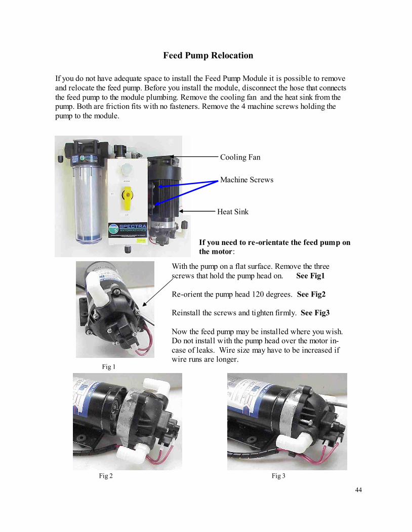
If you do not have adequate space to install the Feed Pump Module it is possible to remove
and relocate the feed pump. Before you install the module, disconnect the hose that connects
the feed pump to the module plumbing. Remove the cooling fan and the heat sink from the
pump. Both are friction fits with no fasteners. Remove the 4 machine screws holding the
pump to the module.
Feed Pump Relocation
Heat Sink
With the pump on a flat surface. Remove the three
screws that hold the pump head on. See Fig1
Re-orient the pump head 120 degrees. See Fig2
Reinstall the screws and tighten firmly. See Fig3
Now the feed pump may be installed where you wish.
Do not install with the pump head over the motor in-
case of leaks. Wire size may have to be increased if
wire runs are longer.
Fig 1
Fig 2 Fig 3
Machine Screws
Cooling Fan
If you need to re-orientate the feed pump on
the motor:
45
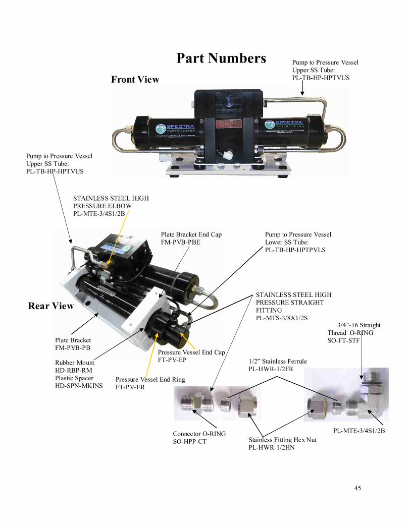
Front View
Rear View
Plate Bracket
FM-PVB-PB
Rubber Mount
HD-RBP-RM
Plastic Spacer
HD-SPN-MKINS
Plate Bracket End Cap
FM-PVB-PBE
Pressure Vessel End Cap
FT-PV-EP
Pressure Vessel End Ring
FT-PV-ER
Part Numbers
Stainless Fitting Hex Nut
PL-HWR-1/2HN
1/2” Stainless Ferrule
PL-HWR-1/2FR
Connector O-RING
SO-HPP-CT
3/4”-16 Straight
Thread O-RING
SO-FT-STF
STAINLESS STEEL HIGH
PRESSURE ELBOW
PL-MTE-3/4S1/2B
STAINLESS STEEL HIGH
PRESSURE STRAIGHT
FITTING
PL-MTS-3/8X1/2S
PL-MTE-3/4S1/2B
Pump to Pressure Vessel
Upper SS Tube:
PL-TB-HP-HPTVUS
Pump to Pressure Vessel
Upper SS Tube:
PL-TB-HP-HPTVUS
Pump to Pressure Vessel
Lower SS Tube:
PL-TB-HP-HPTPVLS
46
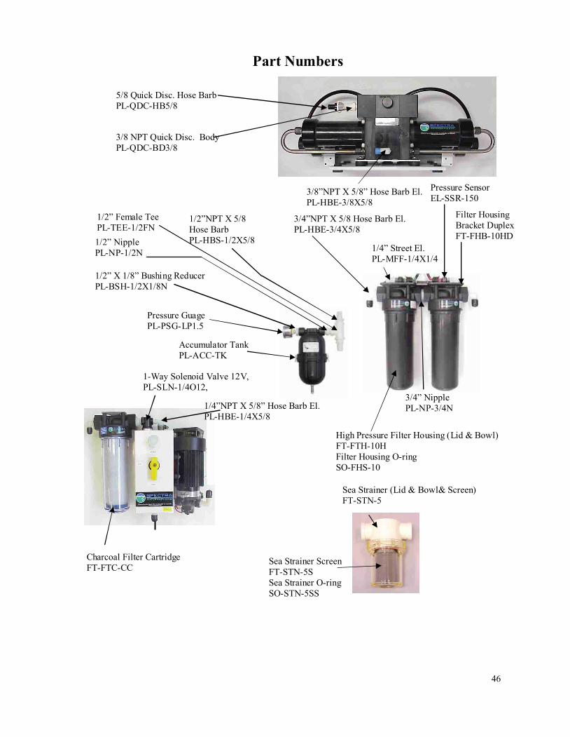
3/8 NPT Quick Disc. Body
PL-QDC-BD3/8
5/8 Quick Disc. Hose Barb
PL-QDC-HB5/8
Sea Strainer (Lid & Bowl& Screen)
FT-STN-5
Sea Strainer Screen
FT-STN-5S
Sea Strainer O-ring
SO-STN-5SS
1-Way Solenoid Valve 12V,
PL-SLN-1/4O12,
1/4”NPT X 5/8” Hose Barb El.
PL-HBE-1/4X5/8
3/4”NPT X 5/8 Hose Barb El.
PL-HBE-3/4X5/8
1/4” Street El.
PL-MFF-1/4X1/4
Pressure Sensor
EL-SSR-150
Filter Housing
Bracket Duplex
FT-FHB-10HD
3/4” Nipple
PL-NP-3/4N
High Pressure Filter Housing (Lid & Bowl)
FT-FTH-10H
Filter Housing O-ring
SO-FHS-10
Accumulator Tank
PL-ACC-TK
Pressure Guage
PL-PSG-LP1.5
1/2” X 1/8” Bushing Reducer
PL-BSH-1/2X1/8N
1/2” Nipple
PL-NP-1/2N
1/2” Female Tee
PL-TEE-1/2FN
1/2”NPT X 5/8
Hose Barb
PL-HBS-1/2X5/8
3/8”NPT X 5/8” Hose Barb El.
PL-HBE-3/8X5/8
Charcoal Filter Cartridge
FT-FTC-CC
Part Numbers
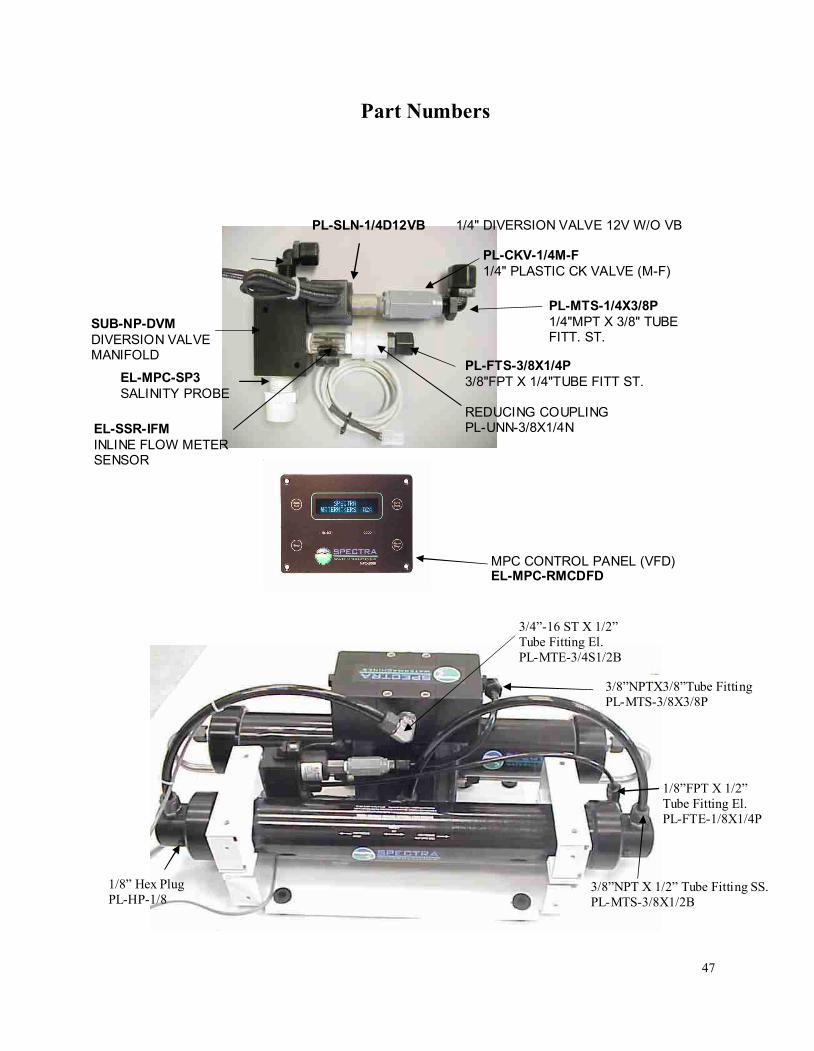
47
3/4”-16 ST X 1/2”
Tube Fitting El.
PL-MTE-3/4S1/2B
3/8”NPTX3/8”Tube Fitting
PL-MTS-3/8X3/8P
3/8”NPT X 1/2” Tube Fitting SS.
PL-MTS-3/8X1/2B
1/8”FPT X 1/2”
Tube Fitting El.
PL-FTE-1/8X1/4P
1/8” Hex Plug
PL-HP-1/8
Part Numbers
EL-MPC-SP3
SALINITY PROBE
SUB-NP-DVM
DIVERSION VALVE
MANIFOLD
PL-MTS-1/4X3/8P
1/4"MPT X 3/8" TUBE
FITT. ST.
EL-SSR-IFM
INLINE FLOW METER
SENSOR
PL-CKV-1/4M-F
1/4" PLASTIC CK VALVE (M-F)
PL-SLN-1/4D12VB 1/4" DIVERSION VALVE 12V W/O VB
PL-FTS-3/8X1/4P
3/8"FPT X 1/4"TUBE FITT ST.
REDUCING COUPLING
PL-UNN-3/8X1/4N
MPC CONTROL PANEL (VFD)
EL-MPC-RMCDFD
48
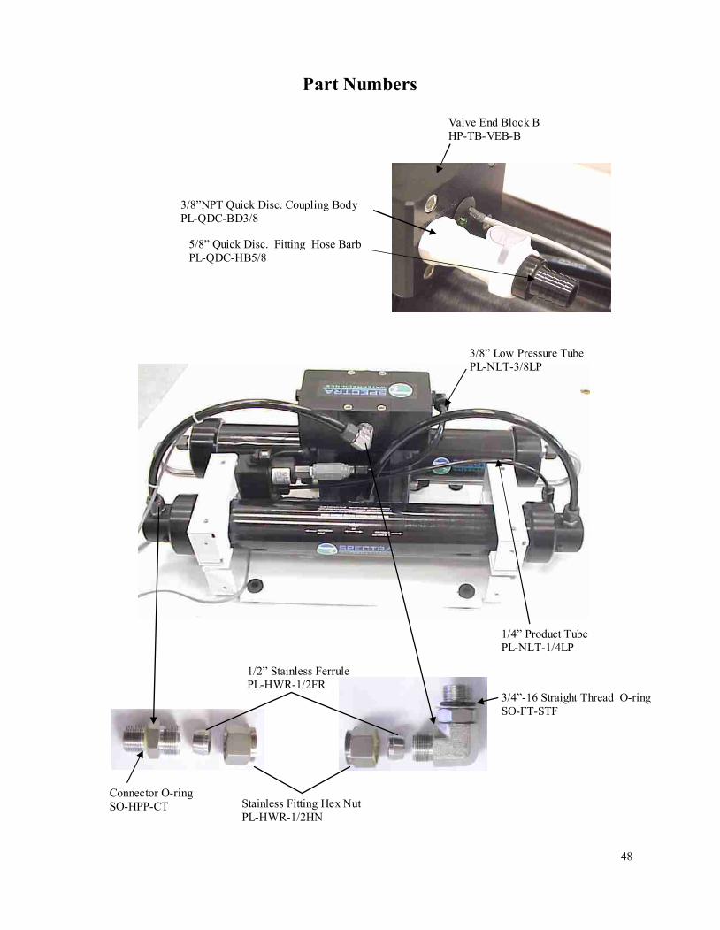
Valve End Block B
HP-TB-VEB-B
3/8”NPT Quick Disc. Coupling Body
PL-QDC-BD3/8
5/8” Quick Disc. Fitting Hose Barb
PL-QDC-HB5/8
1/4” Product Tube
PL-NLT-1/4LP
3/8” Low Pressure Tube
PL-NLT-3/8LP
Stainless Fitting Hex Nut
PL-HWR-1/2HN
1/2” Stainless Ferrule
PL-HWR-1/2FR
Connector O-ring
SO-HPP-CT
3/4”-16 Straight Thread O-ring
SO-FT-STF
Part Numbers
49
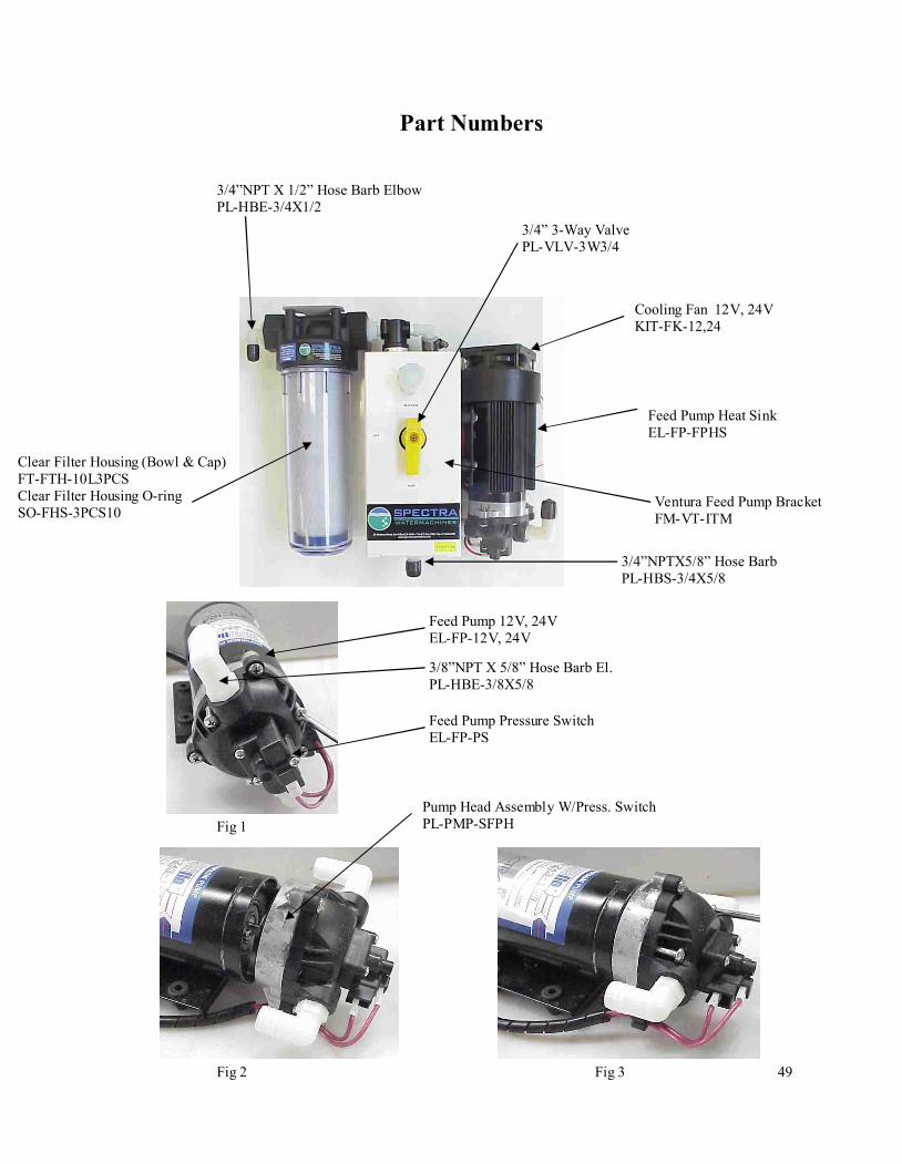
Clear Filter Housing (Bowl & Cap)
FT-FTH-10L3PCS
Clear Filter Housing O-ring
SO-FHS-3PCS10
3/4”NPT X 1/2” Hose Barb Elbow
PL-HBE-3/4X1/2
3/4”NPTX5/8” Hose Barb
PL-HBS-3/4X5/8
Fig 1
Fig 2 Fig 3
3/4” 3-Way Valve
PL-VLV-3W3/4
Cooling Fan 12V, 24V
KIT-FK-12,24
Feed Pump Heat Sink
EL-FP-FPHS
Ventura Feed Pump Bracket
FM-VT-ITM
Feed Pump 12V, 24V
EL-FP-12V, 24V
3/8”NPT X 5/8” Hose Barb El.
PL-HBE-3/8X5/8
Pump Head Assembly W/Press. Switch
PL-PMP-SFPH
Feed Pump Pressure Switch
EL-FP-PS
Part Numbers
50
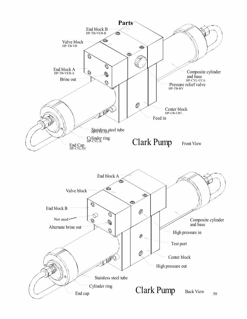
End block B
End Cap
Cylinder ring
Stainless steel tube
End block A
Brine out
Valve block
Pressure relief valve
Center block
Front View
Feed in
Clark Pump
Composite cylinder
and base
End block A
End cap
Cylinder ring
Stainless steel tube
End block B
Valve block
Alternate brine out
Reset button
Not on all units
Test port
Center block
Back View
High pressure out
Clark Pump
High pressure in
Composite cylinder
and base
HP-TB-VEB-B
HP-TB-VB
HP-TB-VEB-A
HP-TB-BV
HP-CB-CB7,
HP-CYL-SST
HP-CYL-R
HP-CYL-EC
HP-CYL-CCA
Parts
Not used
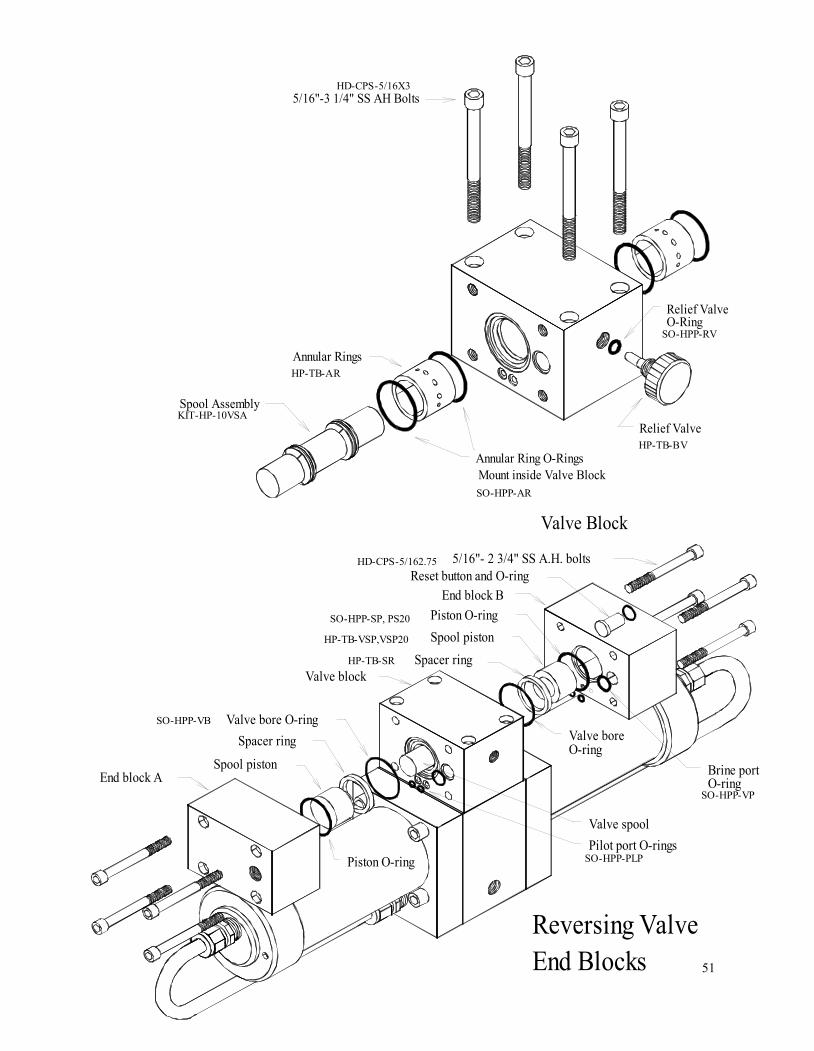
51
5/16"-3 1/4" SS AH Bolts
Spool Seal
Spool End
Spool Assembly
Annular Rings
Spool Center
Quad Ring Seal
Exploded View
Spool Assembly
Spool Seal
Quad Ring Seal
Spool End
Valve Block
Relief Valve
Mount inside Valve Block
Annular Ring O-Rings
Relief Valve
O-Ring
Reset button and O-ring
Spacer ring
Valve spool
Spool piston
End block A
Piston O-ring
Valve bore O-ring
Spacer ring
Valve block
Brine port
O-ring
Pilot port O-rings
Reversing Valve
End Blocks
5/16"- 2 3/4" SS A.H. bolts
Spool piston
Valve bore
O-ring
End block B
Piston O-ring
HD-CPS-5/16X3
KIT-HP-10VSA
HP-TB-AR
SO-HPP-AR
SO-HPP-RV
HP-TB-BV
HD-CPS-5/162.75
SO-HPP-SP, PS20
HP-TB-VSP,VSP20
HP-TB-SR
SO-HPP-VB
SO-HPP-PLP
SO-HPP-VP
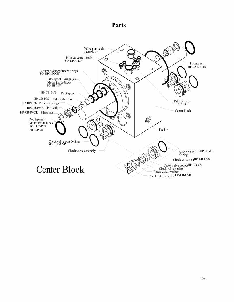
52
Pilot valve port seals
Valve port seals
Pin seals
Center Block
Check valve port O-rings
Piston to rod O-rings (2)
Inside pistons Glass rod models only
Rod lip seals
Mount inside block
Clip rings
Check valve assembly
Center block cylinder O-rings
Pilot spool O-rings (4)
Mount inside block
Pilot valve pin
Pin seal O-rings
Pilot spool
Center block
Check valve poppet
Feed in
Check valve spring
Check valve seat
Check valve
O-ring
Check valve retainer
Check valve washer
Pilot orifice
Piston rod
HP-CYL-3/4R,
SO-HPP-VP
SO-HPP-PLP
SO-HPP-ECCB
SO-HPP-PV
HP-CB-PVS
HP-CB-PPS
SO-HPP-PS
HP-CB-PVPS
HP-CB-PVCR
SO-HPP-PR7,
PR10,PR15
SO-HPP-CVP
HP-CB-PO
SO-HPP-CVS
HP-CB-CVS
HP-CB-CV
HP-CB-CVR
Parts
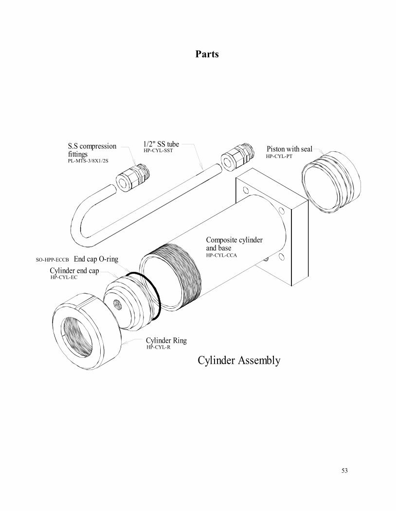
53
Cylinder Assembly
End cap O-ring
Cylinder end cap
Cylinder Ring
S.S compression
fittings
1/2" SS tube
Piston with seal
Composite cylinder
and base
PL-MTS-3/8X1/2S
HP-CYL-SST
HP-CYL-CCA
SO-HPP-ECCB
HP-CYL-EC
HP-CYL-R
HP-CYL-PT
Parts
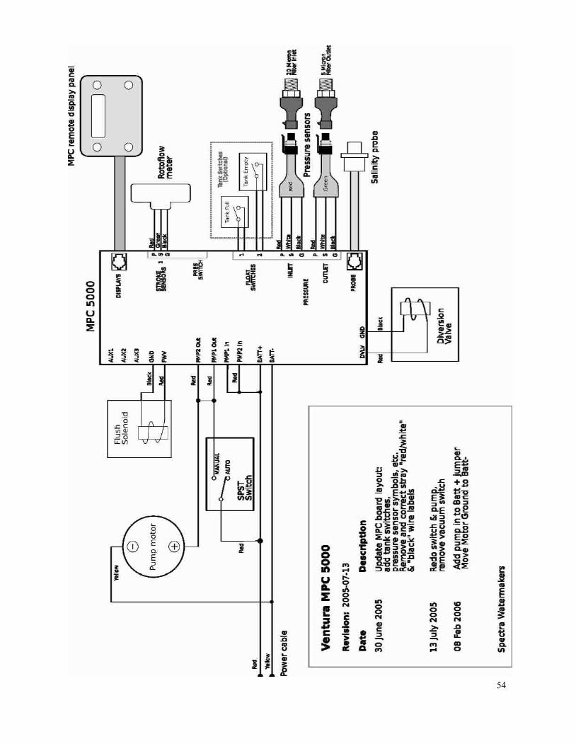
54