Embed Size (px)
Citation preview

Venting Hob installation guidance
Taryn Service

208.06.20Venting Hob installation guidance
Venting Hob ModelsRange Overview
Existing
New April 2020
T58TL6EN2N 9080cm Venting hob, TwistPad Fire, 2xFlex+Ventilation, Climate Control sensor, Automatic Hood, Frying Sensor, Home Connect
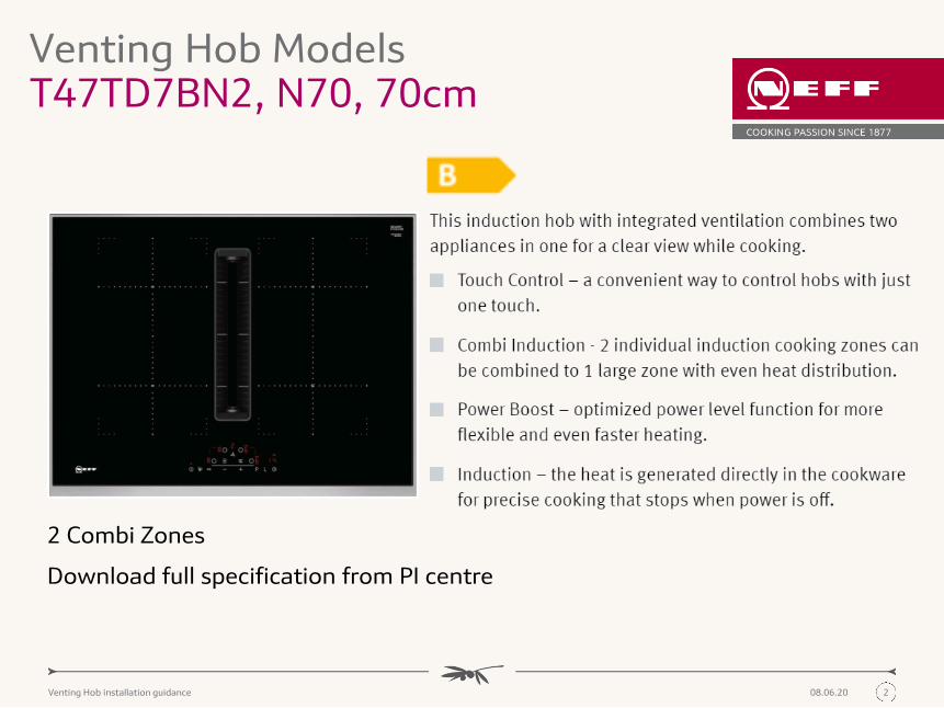
T47TD7BN2N 7070cm Venting hob, Built-in dimension 60cm, Touch Control, 4 zone +Ventilation, 2 x Combi Zone, Frying Sensor, Auto-On fan
T48TD1BN0N 7080cm Venting hob, Touch Control, 4 zone + Ventilation, 1 x Combi Zone, Frying Sensor, Auto-On fan
Pre September 2020
Post September 2020
New April 2020 Discontinued
New September 2020
T58TL6EN2N 9080cm Venting hob, TwistPad Fire, 2xFlex+Ventilation, Climate Control sensor, Automatic Hood, Frying Sensor, Home Connect
T47TD7BN2N 7070cm Venting hob, Built-in dimension 60cm, Touch Control, 4 zone +Ventilation, 2 x Combi Zone, Frying Sensor, Auto-On fan
T48TD7BN2N 7080cm Venting hob, Touch Control, 4 zone + Ventilation, 2 x Combi Zone, Frying Sensor, Auto-On fan
Existing
208.06.20Venting Hob installation guidance
2 Combi Zones
Download full specification from PI centre
Venting Hob ModelsT47TD7BN2, N70, 70cm

308.06.20Venting Hob installation guidance
Venting Hob ModelsT47TD7BN2 Installation
70cm hob can fit
into a 60cm niche
All measurements are in mm
A. Minimum distance from the hob cut-out to the wall
B. Recessing depth (Note- old model depth was
205mm)
C. The worktop into which the hob is installed must
withstand loads of approx. 60kg; suitable
substructures must be used if required. Hob
weight: approx. 24kg. Hob requires a 16mm work
surface thickness minimum.
D. Cut-out in back panel required for pipework. Exact
size and position can be taken from specific
drawing.

408.06.20Venting Hob installation guidance
Venting Hob ModelsT47TD7BN2 Cut out requirements
Partly ducted recirculation or fully
Ducted cut out requirements
Unducted recirculation cut out
requirements
All measurements are in mm
During installation the cut out required for the air outlet might vary depending on the type of recirculation/ducting selected

508.06.20Venting Hob installation guidance
Venting Hob ModelsT48TD7BN2, N70, 80cm
2 CombiZonesDownload full specification from PI centre

608.06.20Venting Hob installation guidance
Venting Hob ModelsT48TD7BN2 Installation
All measurements are in mm
A. Minimum distance from the hob cut-out to the wall
B. Recessing depth (Note- old model depth was
205mm)
C. The worktop into which the hob is installed must
withstand loads of approx. 60kg; suitable
substructures must be used if required. Hob
weight: approx. 28kg. Hob requires a 16mm work
surface thickness minimum.
D. Cut-out in back panel required for pipework. Exact
size and position can be taken from specific
drawing.

708.06.20Venting Hob installation guidance
Venting Hob ModelsT48TD7BN2 Cut out requirements
All measurements are in mm
Partly ducted recirculation or fully
Ducted cut out requirements
Unducted recirculation cut out
requirements
During installation the cut out required for the air outlet might vary depending on the type of recirculation/ducting selected

508.06.20Venting Hob installation guidance
Venting Hob ModelsT58TL6EN2, N90, 80cm
2 FlexInduction zonesDownload full specification from PI centre

608.06.20Venting Hob installation guidance
Venting Hob ModelsT58TL6EN2 Installation
All measurements are in mm
A. Minimum distance from the hob cut-out to the wall
B. Recessing depth (Note- old model depth was
205mm)
C. The worktop into which the hob is installed must
withstand loads of approx. 60kg; suitable
substructures must be used if required. Hob
weight: approx. 28kg. Hob requires a 16mm work
surface thickness minimum.
D. Cut-out in back panel required for pipework. Exact
size and position can be taken from specific
drawing.

708.06.20Venting Hob installation guidance
Venting Hob ModelsT58TL6EN2 Cut out requirements
All measurements are in mm
Partly ducted recirculation or fully
Ducted cut out requirements
Unducted recirculation cut out
requirements
During installation the cut out required for the air outlet might vary depending on the type of recirculation/ducting selected

508.06.20Venting Hob installation guidance
Venting Hob ModelsCut out variants 80cm
Previous Model- T48TD1BN0 New Model- T48TD7BN2, T58TL6EN2
Please Note: Bracket to fit to the edge 490-500 on the old model would hold the hobs in place. If there is a bigger aperture based on previous models dimensions the customer ought not worry as the new models are supplied with some plastic spacer pieces which attach to the edge of the hob to fit into the previous aperture size
508.06.20Venting Hob installation guidance
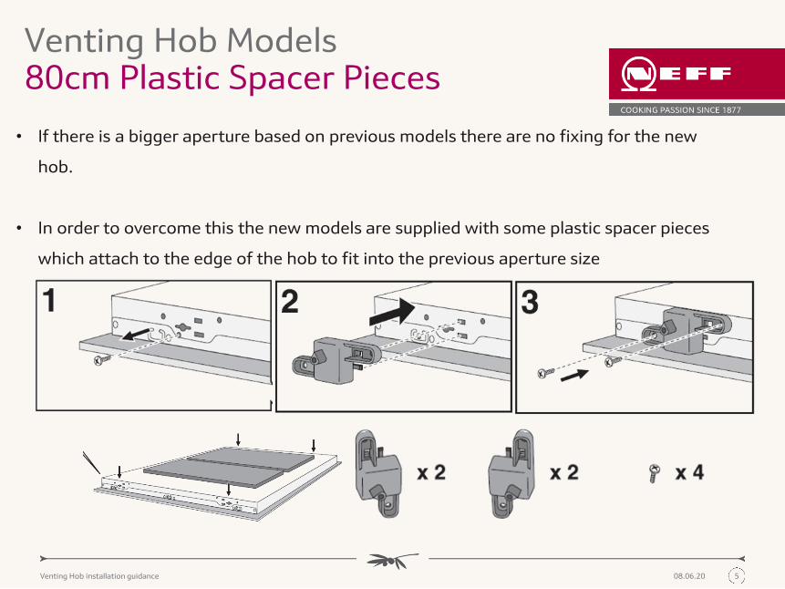
Venting Hob Models80cm Plastic Spacer Pieces
• If there is a bigger aperture based on previous models there are no fixing for the new
hob.
• In order to overcome this the new models are supplied with some plastic spacer pieces
which attach to the edge of the hob to fit into the previous aperture size

808.06.20Venting Hob installation guidance
Venting Hob ModelsKey Features
The same for both models
1. Black metal grease filter (200ml of liquid can be
held)
2. Activated charcoal filter for air recirculation or
acoustics filter for air extraction*
3. Hob
4. Control panel
5. Overflow container (700ml of liquid can be
held), which is accessed from the front under
the hob.
*Depending on the appliance specifications

908.06.20Venting Hob installation guidance
Venting Hob ModelsElectrical Connection
The same for both models
• We recommend connecting the cable to the product before inserting it into
the worktop, this makes it easier to install
• See the installation manual for more information on establishing a connection
to the mains.
Ensure that the power cable is only installed or replaced by a qualified electrician

1008.06.20Venting Hob installation guidance
Types of Installation
UnductedRecirculation
Customised Partly Ducted Recirculation
Customised Fully Ducted Recirculation
Ducted Exhaust Extraction (to the
outside)
1108.06.20Venting Hob installation guidance
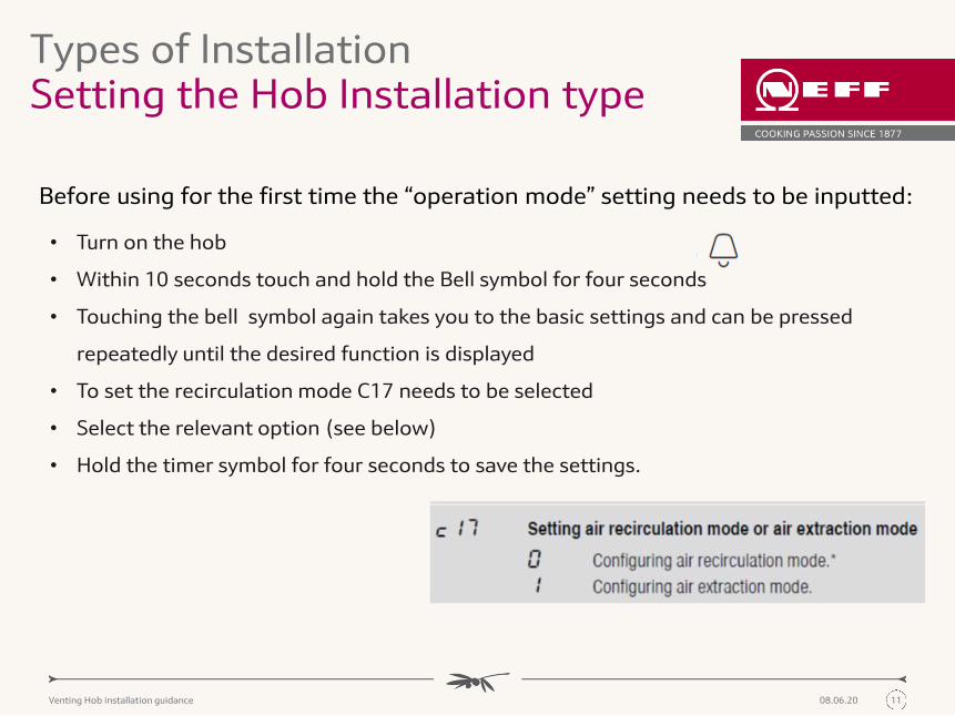
Types of InstallationSetting the Hob Installation type
• Turn on the hob
• Within 10 seconds touch and hold the Bell symbol for four seconds
• Touching the bell symbol again takes you to the basic settings and can be pressed
repeatedly until the desired function is displayed
• To set the recirculation mode C17 needs to be selected
• Select the relevant option (see below)
• Hold the timer symbol for four seconds to save the settings.
Before using for the first time the “operation mode” setting needs to be inputted:

1208.06.20Venting Hob installation guidance
Types of Installation Unducted Recirculation
• Allows for full depth drawers
• Min. void gap of 50mm recommended for optimum performance
• Fan runs for 30 minutes after use at speed 1 to draw air through
filters, to dry them and move any moisture through the void at the
back of the appliance
• Minimum worktop depth: 60cm
• Suitable for island installations
• No ducting materials required- Slider accessory instead
• This is NOT suitable for installations against a single cavity non
insulated walls Example Images only
Reliant on the hob and the furniture to disperse air- Uses the void at the back of the appliance and the furniture to
recirculate the air.

1308.06.20Venting Hob installation guidance
Types of Installation Types of Installation Unducted recirculation example
1408.06.20Venting Hob installation guidance
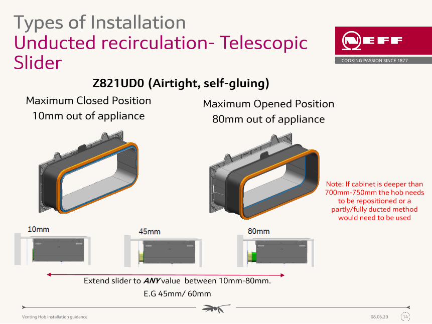
Unducted recirculation- Telescopic Slider
Types of Installation Types of Installation
Maximum Closed Position
10mm out of applianceMaximum Opened Position
80mm out of appliance
Extend slider to ANY value between 10mm-80mm.
E.G 45mm/ 60mm
Z821UD0 (Airtight, self-gluing)
Note: If cabinet is deeper than 700mm-750mm the hob needs
to be repositioned or a partly/fully ducted method
would need to be used

1508.06.20Venting Hob installation guidance
Types of Installation Unducted recirculation- Inserting the telescopic Slider
• Insert the slider into the hob before it is installed into
the furniture
• Ensure the air outlet cut out is the right side for the
installation (see slide 4/7)
• Once inserted into the furniture the telescopic slider
can be extended between a distance of 10mm to
80mm
• If necessary the adapter can be secured into place
using screws

1508.06.20Venting Hob installation guidance
PLEASE NOTE: Slider is ONLY for use in the unductedinstallation- not as a connector piece
for ducting panels

1608.06.20Venting Hob installation guidance
Types of Installation Partly ducted Recirculation
• Requires reduced depth drawers
• Suitable both for island installations or installations against a single
wall without installation
• Minimum worktop depth: 70cm
• Requires ducting panels to be purchased separately for installation-
however requires less ducting than fully ducting
• Ducting panels insert into the back of the hob directly
• Fan runs for 30 minutes after use at speed 1 to draw air through
filters, to dry them and move any excessive moisture and odors
Example Images only
Relies on a combination of ducting and furniture to disperse the air- Uses ducting to guide air partially around the
furniture then uses the remaining void.

1708.06.20Venting Hob installation guidance
Types of Installation Fully ducted Recirculation
Relies solely on ducting panels to disperse the air from the appliance to the furniture plinth.
• Requires reduced depth drawers- ducting required is 94mm and needs
to be accounted for
• Suitable both for installations against a single wall without installation
• Minimum worktop depth: 70cm
• Requires full ducting panels to be purchased separately for installation
• Requires planning the recirculation route for the ducting panels
• Ducting panels insert into the back of the hob directly
• Fan runs for 12 minutes after use at speed 1 to draw air through filters,
to dry them and move any moisture

1808.06.20Venting Hob installation guidance
Types of Installation Ducted Exhaust Extraction
• Adequate performance over 8m of ducting with up to 3 X 90º bends
• Ideal for those looking to extract to the outside
• Minimum worktop depth: 70cm
• Requires reduced depth drawers- ducting required is 94mm and needs
to be accounted for
• Requires ducting panels to be sourced for installation.
• Requires planning the extraction route and outlet for the ducting panels
• Ducting panels insert into the back of the hob directly
• Fan runs for 12 minutes after use at speed 1 to draw air through filters,
to dry them and move any moisture
Relies solely on ducting panels to disperse the air from the appliance to the outside.
Example Images only

1908.06.20Venting Hob installation guidance
Types of Installation Installing ducting for partly/fully ducted recirc. or ducted exhaust extraction
• Install the hob into the unit and ensure the cut outs are made for the
air outlet (See slide 4/7).
• Use the adhesive seal to secure the ducting panel directly to the air
outlet on the cooktop.
• Connect the relevant ducting panels
• Finally connect the diffuser for partly or fully recirculated installation
or the relevant extraction components for ducted exhaust extraction
installation.
• If using ducted recirculation ensure there is an area of a minimum of
400 cm² in the plinth for return air flow into the kitchen
Note: All ducting panels need to be sourced separately- not available from Neff.
Diffuser relevant for either fully or partly
recirculated installation

2008.06.20Venting Hob installation guidance
Unducted RecirculationCustomised Partly Ducted
RecirculationCustomised Fully Ducted
RecirculationDucted Exhaust Extraction
Neff Venting Hob Installation Options & Requirements
Venting Hobs
T58TL6EN2 T58TL6EN2 T58TL6EN2 T58TL6EN2T47TD7BN2 T47TD7BN2 T47TD7BN2 T47TD7BN2T48TD7BN2 T48TD7BN2 T48TD7BN2 T48TD7BN2
Required Neff Accessory Z821UD0 Z821PD0 Z821PD0 Z811DU0
Accessory contents
1 x Telescopic "slider" (self-adhesive, air tight seal)
4 x Clean Air Odour Filters
1 x Air diffuser
4 x Clean Air Odour Filters
1 x Adhesive seal
1 x Air diffuser
4 x Clean Air Odour Filters
1 x Adhesive seal
4 x Acoustic noise reducing filters
1 x Adhesive seal
Additional required Accessories (not available from Neff)
NoneFlat ducting elements - to suit flat channel ducting approx.
220x90mm
Flat ducting elements - to suit flat channel ducting approx.
220x90mm
Flat ducting elements - to suit flat channel ducting approx.
220x90mm
Installation Overview

1908.06.20Venting Hob installation guidance
Types of Installation Example of Installation Requirements- UnductedRecirculation
Unducted RecirculationRequirements:
• Z821UD0
AdhesiveSeal
Telescopic Slider
All imagery is example onlyCurrently not supplied by BSH
1908.06.20Venting Hob installation guidance
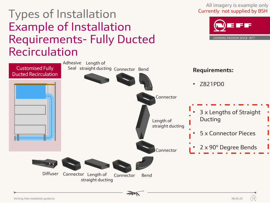
Types of Installation Example of Installation Requirements- Fully Ducted Recirculation
All imagery is example only
Connector Bend
Connector BendCustomised Fully Ducted Recirculation
Requirements:
• Z821PD0
• 3 x Lengths of Straight Ducting
• 5 x Connector Pieces
• 2 x 90º Degree Bends
Diffuser
Connector
Length of straight ducting
Connector
AdhesiveSeal
Length of straight ducting
Connector Length of straight ducting
Currently not supplied by BSH

1908.06.20Venting Hob installation guidance
Types of Installation Example of Installation Requirements- Ducted Exhaust Extraction
All imagery is example only
Connector BendFully Ducted Exhaust Extraction
Requirements:
• Z811DU0
• 2 x Lengths of Straight Ducting
• 4 x Connector Pieces
• 2 x 90º Degree Bends
• 1 x External Cover (Ventilation Grid)
Connector
Length of straight ducting
Connector
AdhesiveSeal
Length of straight ducting
Bend Connector Ventilation Grid
Currently not supplied by BSH


![PIDD [en] Instruction manual Hob - BSH Hausgerätemedia3.bsh-group.com/Documents/9001063685_E.pdf · energy and disposing of the appliance. Energy-saving advice Always use the correct](https://img.pdfslide.us/doc/110x75/5f0cfcfb7e708231d4381f5c/pidd-en-instruction-manual-hob-bsh-hausger-energy-and-disposing-of-the-appliance.jpg)


![[en]Instruction manualmedia3.bsh-group.com/Documents/9000751800_A.pdf · 4 Elements that may damage the appliance Caution! Rough pan bases may scratch the hob. Avoid leaving empty](https://img.pdfslide.us/doc/110x75/5e7fd765416303560a38794f/eninstruction-4-elements-that-may-damage-the-appliance-caution-rough-pan-bases.jpg)