Embed Size (px)
Citation preview
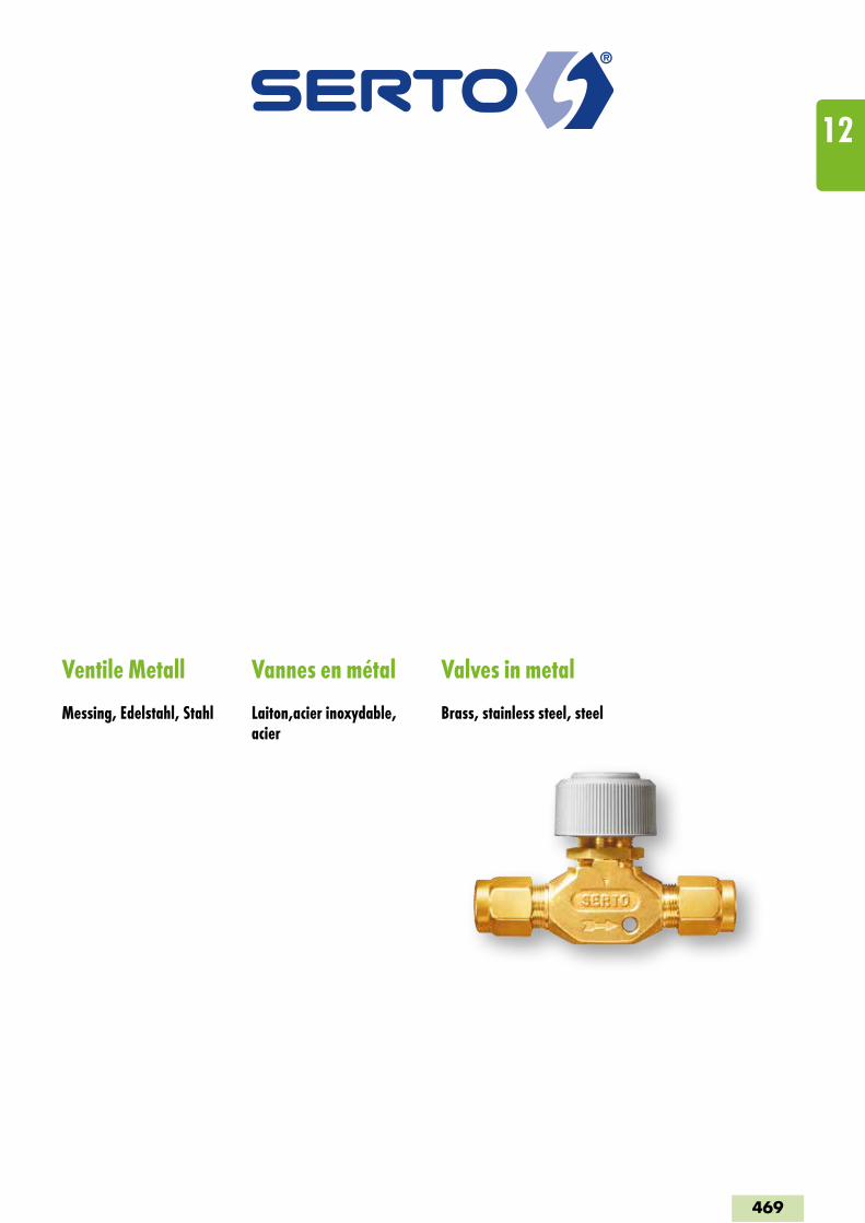
Ventile Metall
Messing, Edelstahl, Stahl
Vannes en métal
Laiton,acier inoxydable, acier
Valves in metal
Brass, stainless steel, steel
469
12
Ventile Messing MVannes laiton MValves brass M
475-477RegulierventilVanne de réglageRegulating valve
SO NV 41A21
478FeinregulierventilVanne de réglage finFine regulating valve
SO NV 41C21
479-483Regulier-EckventilVanne-équerre de réglageElbow regulating valve
SO NV 41A21E
484-486Feinregulier-EckventilVanne-équerre de réglage finElbow fine regulating valve
SO NV 41C21E
489-491KegelrückschlagventilClapet anti-retour à siège coniqueTaper seat non-return valve
SO CV 43A21
492DoppelkugelrückschlagventilSoupape de retenue à deux billesDouble ball non-return valve
SO CV 43B01
493DoppelschutzventilVanne à double protectionDouble action valve
SO CV 43C21
494-495SchwenkverschraubungCoude banjoSingle banjo
SO 47724
496-498Mini-KugelhahnMini vanne à billeMini-ball valve
SO BV 48A00
Ventile Messing GVannes laiton GValves brass G
501-503RegulierventilVanne de réglageRegulating valve
SO NV 01A21
504FeinregulierventilVanne de réglage finFine regulating valve
SO NV 01C21
507-509Regulier-EckventilVanne-équerre de réglageElbow regulating valve
SO NV 01A21E
510Feinregulier-EckventilVanne-équerre de réglage finElbow fine regulating valve
SO NV 01C21E
511Dosier-EckventilVanne-équerre de réglage de précisionMetering elbow valve
SO NV 01D21E
514-516KegelrückschlagventilClapet anti-retour à siège coniqueTaper seat non-return valve
SO CV 03A21
517Kugelhahn voller DurchgangVanne à bille avec passage totalBall valve with full flow
SO BV 08C00
518DurchgangshahnVanne simple à passage directTotal-flow cock
SO PV 08E01
Ventile EdelstahlVannes acier inoxydableValves stainless steel
522-524RegulierventilVanne de réglageRegulating valve
SO NV 51A00
525FeinregulierventilVanne de réglage finFine regulating valve
SO NV 51C00
526DosierventilVanne de réglage de précisionMetering valve
SO NV 51D21
527-530Regulier-EckventilVanne-équerre de réglageElbow regulating valve
SO NV 51A21E
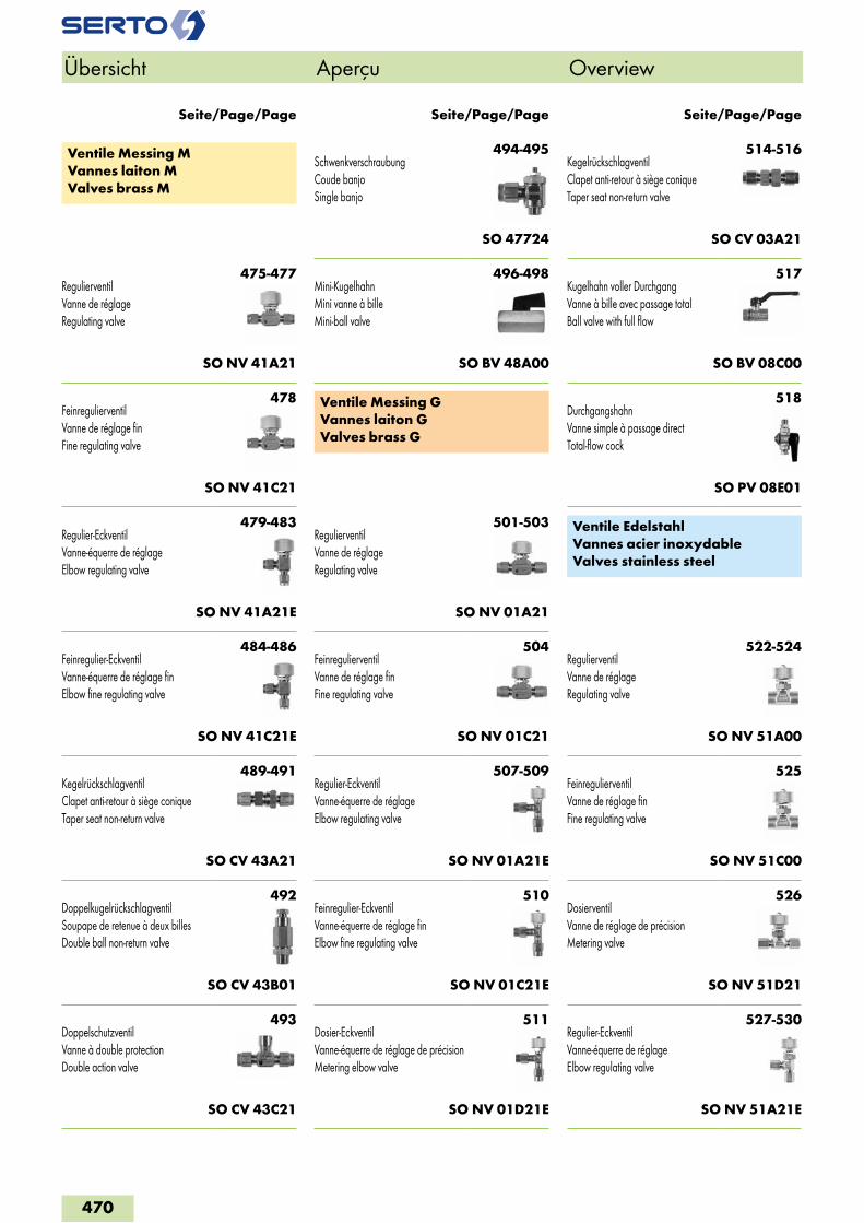
Seite/Page/Page Seite/Page/Page Seite/Page/Page
Übersicht Aperçu Overview
470
531-532Feinregulier-EckventilVanne-équerre de réglage finElbow fine regulating valve
SO NV 51C21E
535-537KegelrückschlagventilClapet anti-retour à siège coniqueTaper seat non-return valve
SO CV 53B21
538-541KugelhahnVanne à billeBall valve
SO BV 58A00
542-543NadelventilVanne à pointeauNeedle valve
SO NV 51B00
Ventile Edelstahl LVannes acier inoxydable LValves stainless steel L
546Hochdruck-Kugelhahn SOLVanne à bille SOL haute pressionHigh pressure ball valve SOL
SOL BV 58A21
547KegelrückschlagventilClapet anti-retour à siège coniqueTaper seat non-return valve
SOL CV 53B21
Ventile StahlVannes acierValves steel
550KegelrückschlagventilSoupape de retenue à siège coniqueTaper seat non-return valve
SO 6611
Ventile ZubehörVannes accessoriesValves accessories
551AnschraubfussSupport de fixationFlange mount
SO 09900
552Ventilschilder (Satz)Plaques signalétiques (set)Valve labels (set)
VSD SO NV
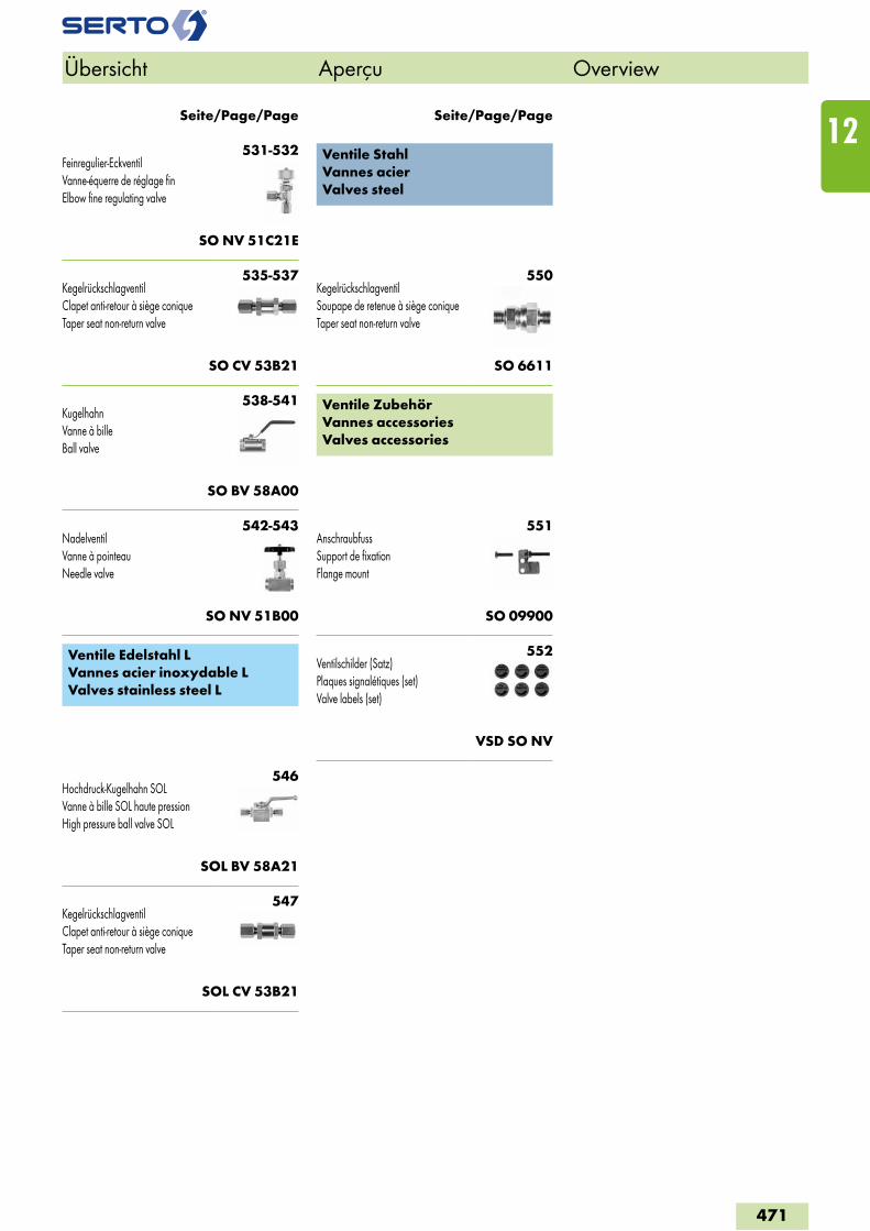
Seite/Page/Page Seite/Page/Page
Übersicht Aperçu Overview
471
12
Ventile Messing MVannes laiton MValves brass M
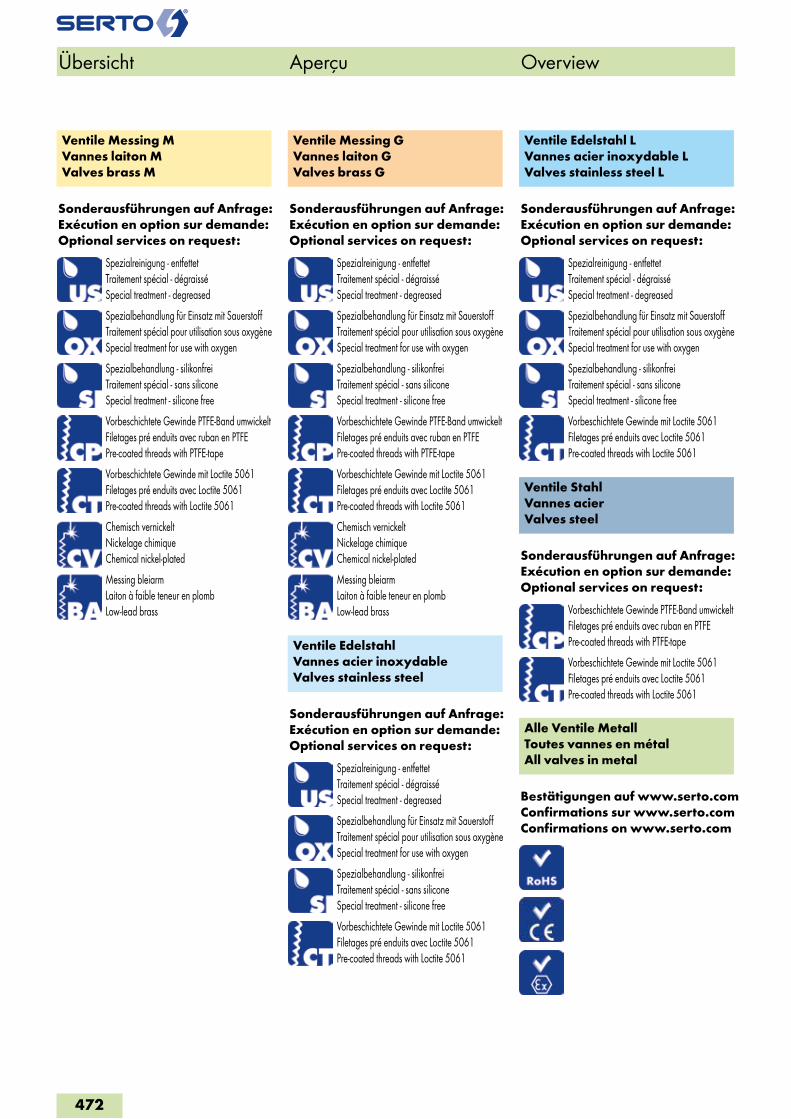
Sonderausführungen auf Anfrage:Exécution en option sur demande:Optional services on request:
Spezialreinigung - entfettetTraitement spécial - dégraisséSpecial treatment - degreased
Spezialbehandlung für Einsatz mit SauerstoffTraitement spécial pour utilisation sous oxygèneSpecial treatment for use with oxygen
Spezialbehandlung - silikonfreiTraitement spécial - sans siliconeSpecial treatment - silicone free
Vorbeschichtete Gewinde PTFE-Band umwickeltFiletages pré enduits avec ruban en PTFEPre-coated threads with PTFE-tape
Vorbeschichtete Gewinde mit Loctite 5061Filetages pré enduits avec Loctite 5061Pre-coated threads with Loctite 5061
Chemisch vernickeltNickelage chimiqueChemical nickel-plated
Messing bleiarmLaiton à faible teneur en plombLow-lead brass
Ventile Messing GVannes laiton GValves brass G
Sonderausführungen auf Anfrage:Exécution en option sur demande:Optional services on request:
Spezialreinigung - entfettetTraitement spécial - dégraisséSpecial treatment - degreased
Spezialbehandlung für Einsatz mit SauerstoffTraitement spécial pour utilisation sous oxygèneSpecial treatment for use with oxygen
Spezialbehandlung - silikonfreiTraitement spécial - sans siliconeSpecial treatment - silicone free
Vorbeschichtete Gewinde PTFE-Band umwickeltFiletages pré enduits avec ruban en PTFEPre-coated threads with PTFE-tape
Vorbeschichtete Gewinde mit Loctite 5061Filetages pré enduits avec Loctite 5061Pre-coated threads with Loctite 5061
Chemisch vernickeltNickelage chimiqueChemical nickel-plated
Messing bleiarmLaiton à faible teneur en plombLow-lead brass
Ventile EdelstahlVannes acier inoxydableValves stainless steel
Sonderausführungen auf Anfrage:Exécution en option sur demande:Optional services on request:
Spezialreinigung - entfettetTraitement spécial - dégraisséSpecial treatment - degreased
Spezialbehandlung für Einsatz mit SauerstoffTraitement spécial pour utilisation sous oxygèneSpecial treatment for use with oxygen
Spezialbehandlung - silikonfreiTraitement spécial - sans siliconeSpecial treatment - silicone free
Vorbeschichtete Gewinde mit Loctite 5061Filetages pré enduits avec Loctite 5061Pre-coated threads with Loctite 5061
Ventile Edelstahl LVannes acier inoxydable LValves stainless steel L
Sonderausführungen auf Anfrage:Exécution en option sur demande:Optional services on request:
Spezialreinigung - entfettetTraitement spécial - dégraisséSpecial treatment - degreased
Spezialbehandlung für Einsatz mit SauerstoffTraitement spécial pour utilisation sous oxygèneSpecial treatment for use with oxygen
Spezialbehandlung - silikonfreiTraitement spécial - sans siliconeSpecial treatment - silicone free
Vorbeschichtete Gewinde mit Loctite 5061Filetages pré enduits avec Loctite 5061Pre-coated threads with Loctite 5061
Ventile StahlVannes acierValves steel
Sonderausführungen auf Anfrage:Exécution en option sur demande:Optional services on request:
Vorbeschichtete Gewinde PTFE-Band umwickeltFiletages pré enduits avec ruban en PTFEPre-coated threads with PTFE-tape
Vorbeschichtete Gewinde mit Loctite 5061Filetages pré enduits avec Loctite 5061Pre-coated threads with Loctite 5061
Alle Ventile MetallToutes vannes en métalAll valves in metal
Bestätigungen auf www.serto.comConfirmations sur www.serto.comConfirmations on www.serto.com
Übersicht Aperçu Overview
472
2
5
1
SO NV 41A21/E/EB/ELSO NV 41C21/E/EB/EL
3
4
6
9
7
8
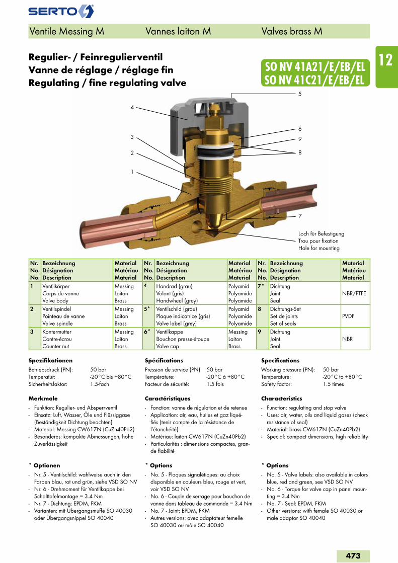
Regulier- / FeinregulierventilVanne de réglage / réglage finRegulating / fine regulating valve
Nr.No.No.
BezeichnungDésignationDescription
MaterialMatériauMaterial
Nr.No.No.
BezeichnungDésignationDescription
MaterialMatériauMaterial
Nr.No.No.
BezeichnungDésignationDescription
MaterialMatériauMaterial
1 VentilkörperCorps de vanneValve body
MessingLaitonBrass
4 Handrad (grau)Volant (gris)Handwheel (grey)
PolyamidPolyamidePolyamide
7* DichtungJointSeal
NBR/PTFE
2 VentilspindelPointeau de vanneValve spindle
MessingLaitonBrass
5* Ventilschild (grau)Plaque indicatrice (gris)Valve label (grey)
PolyamidPolyamidePolyamide
8 Dichtungs-SetSet de jointsSet of seals
PVDF
3 KontermutterContre-écrouCounter nut
MessingLaitonBrass
6* VentilkappeBouchon presse-étoupeValve cap
MessingLaitonBrass
9 DichtungJointSeal
NBR
Spezifikationen
Betriebsdruck (PN): 50 barTemperatur: -20°C bis +80°CSicherheitsfaktor: 1.5-fach
Merkmale
- Funktion: Regulier- und Absperrventil- Einsatz: Luft, Wasser, Öle und Flüssiggase
(Beständigkeit Dichtung beachten)- Material: Messing CW617N (CuZn40Pb2)- Besonderes: kompakte Abmessungen, hohe
Zuverlässigkeit
* Optionen
- Nr. 5 - Ventilschild: wahlweise auch in den Farben blau, rot und grün, siehe VSD SO NV
- Nr. 6 - Drehmoment für Ventilkappe bei Schalttafelmontage = 3.4 Nm
- Nr. 7 - Dichtung: EPDM, FKM- Varianten: mit Übergangsmuffe SO 40030
oder Übergangsnippel SO 40040
Spécifications
Pression de service (PN): 50 barTempérature: -20°C à +80°CFacteur de sécurité: 1.5 fois
Caractéristiques
- Fonction: vanne de régulation et de retenue- Application: air, eau, huiles et gaz liqué-
fiés (tenir compte de la résistance de l’étanchéité)
- Matériau: laiton CW617N (CuZn40Pb2)- Particularités : dimensions compactes, gran-
de fiabilité
* Options
- No. 5 - Plaques signalétiques: au choix disponible en couleurs bleu, rouge et vert, voir VSD SO NV
- No. 6 - Couple de serrage pour bouchon de vanne dans tableau de commande = 3.4 Nm
- No. 7 - Joint: EPDM, FKM- Autres versions: avec adaptateur femelle
SO 40030 ou mâle SO 40040
Specifications
Working pressure (PN): 50 barTemperature: -20°C to +80°CSafety factor: 1.5 times
Characteristics
- Function: regulating and stop valve- Uses: air, water, oils and liquid gases (check
resistance of seal) - Material: brass CW617N (CuZn40Pb2)- Special: compact dimensions, high reliability
* Options
- No. 5 - Valve labels: also available in colors blue, red and green, see VSD SO NV
- No. 6 - Torque for valve cap in panel moun-ting = 3.4 Nm
- No. 7 - Seal: EPDM, FKM- Other versions: with female SO 40030 or
male adaptor SO 40040
Ventile Messing M Vannes laiton M Valves brass M
Loch für BefestigungTrou pour fixationHole for mounting
473
12
SO NV 41C21SO NV 41A21
SO NV 41A21E / A21EB / A21EL SO NV 41C21E / C21EB / 21EL
Ventile Messing M Vannes laiton M Valves brass M
Exécutions en option
voir aperçu du chapitre
Accessoires
Support de fixation pour les types SO NV 41A21 et SO NV 41C21 voir SO 09900
Optional services
see chapter overview
Accessoires
Flange mount for wall fastening for types SO NV 41A21 and SO NV 41C21 see SO 09900
Sonderausführungen
siehe Kapitelübersicht
Zubehör
Anschraubfuss für Wandmontage der Typen SO NV 41A21 und SO NV 41C21 siehe SO 09900
0
5
10
15
20
25
Kv [l
/min
]
Spindelumdrehungen / Tour de Broche / Spindle turns
0.0 1.0 2.0 3.0 4.0 5.0 6.0 7.0 8.0 9.0
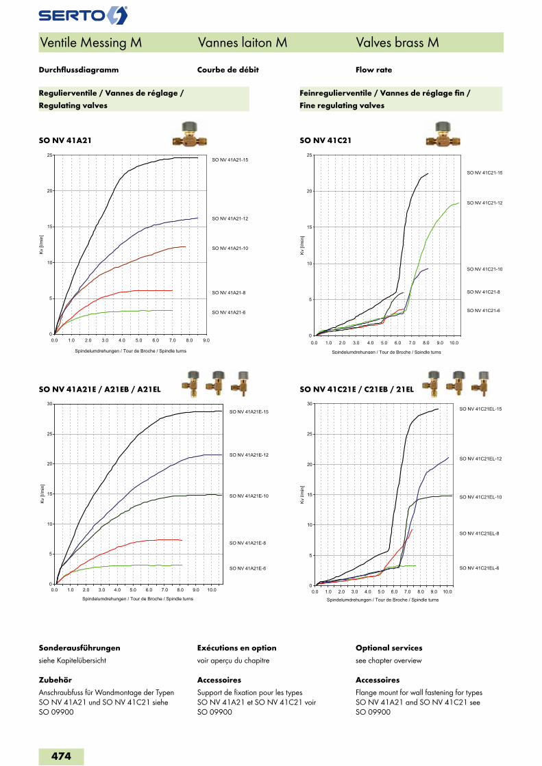
SO NV 41A21-6
SO NV 41A21-8
SO NV 41A21-10
SO NV 41A21-12
SO NV 41A21-15
0
5
10
15
20
25
0.0 1.0 2.0 3.0 4.0 5.0 6.0 7.0 8.0 9.0 10.0
Kv [l
/min
]
Spindelumdrehungen / Tour de Broche / Spindle turns
SO NV 41C21-6
SO NV 41C21-8
SO NV 41C21-10
SO NV 41C21-12
SO NV 41C21-15
0
5
10
15
20
25
30
0.0 1.0 2.0 3.0 4.0 5.0 6.0 7.0 8.0 9.0 10.0
Kv [l
/min
]
Spindelumdrehungen / Tour de Broche / Spindle turns
SO NV 41A21E-6
SO NV 41A21E-8
SO NV 41A21E-10
SO NV 41A21E-12
SO NV 41A21E-15
0
5
10
15
20
25
30
0.0 1.0 2.0 3.0 4.0 5.0 6.0 7.0 8.0 9.0 10.0
Kv l/
min
]
Spindelumdrehungen / Tour de Broche / Spindle turns
SO NV 41C21EL-6
SO NV 41C21EL-8
SO NV 41C21EL-10
SO NV 41C21EL-12
SO NV 41C21EL-15
Courbe de débit Flow rateDurchflussdiagramm
Regulierventile / Vannes de réglage /
Regulating valves
Feinregulierventile / Vannes de réglage fin /
Fine regulating valves
474
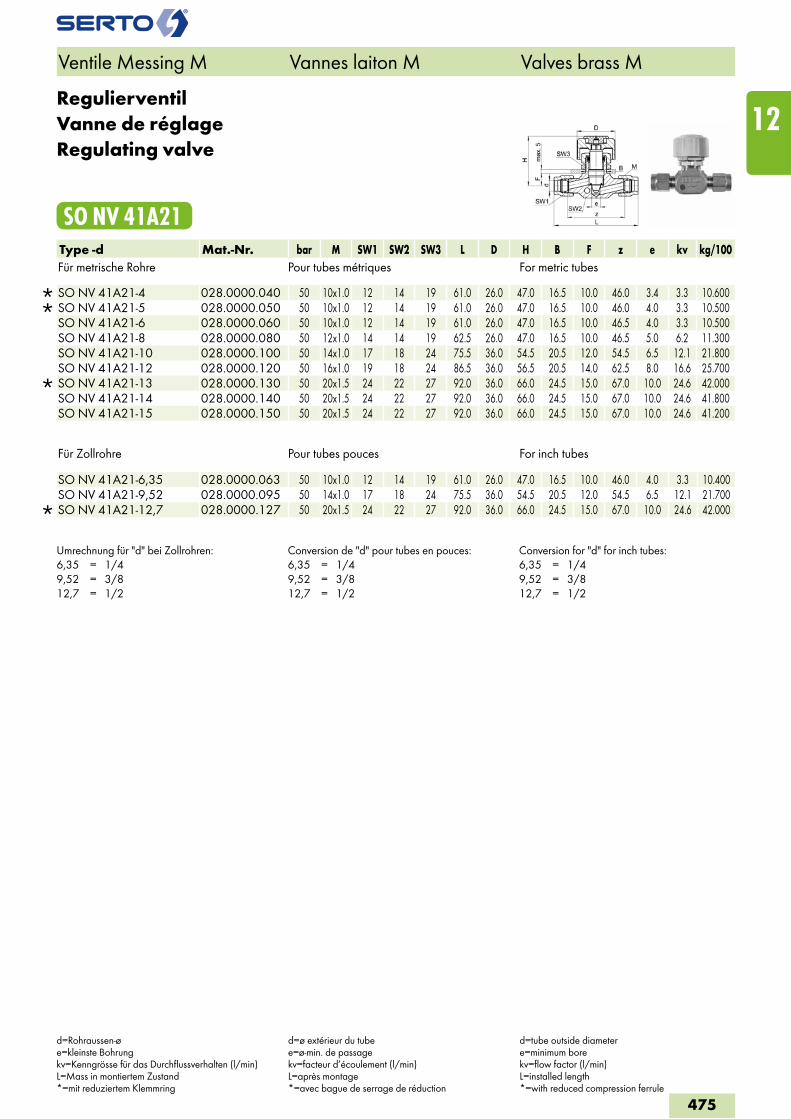
RegulierventilVanne de réglageRegulating valve
SO NV 41A21Type -d Mat.-Nr. bar M SW1 SW2 SW3 L D H B F z e kv kg/100Für metrische Rohre Pour tubes métriques For metric tubes
SO NV 41A21-4 028.0000.040 50 10x1.0 12 14 19 61.0 26.0 47.0 16.5 10.0 46.0 3.4 3.3 10.600 SO NV 41A21-5 028.0000.050 50 10x1.0 12 14 19 61.0 26.0 47.0 16.5 10.0 46.0 4.0 3.3 10.500 SO NV 41A21-6 028.0000.060 50 10x1.0 12 14 19 61.0 26.0 47.0 16.5 10.0 46.5 4.0 3.3 10.500 SO NV 41A21-8 028.0000.080 50 12x1.0 14 14 19 62.5 26.0 47.0 16.5 10.0 46.5 5.0 6.2 11.300 SO NV 41A21-10 028.0000.100 50 14x1.0 17 18 24 75.5 36.0 54.5 20.5 12.0 54.5 6.5 12.1 21.800 SO NV 41A21-12 028.0000.120 50 16x1.0 19 18 24 86.5 36.0 56.5 20.5 14.0 62.5 8.0 16.6 25.700
SO NV 41A21-13 028.0000.130 50 20x1.5 24 22 27 92.0 36.0 66.0 24.5 15.0 67.0 10.0 24.6 42.000 SO NV 41A21-14 028.0000.140 50 20x1.5 24 22 27 92.0 36.0 66.0 24.5 15.0 67.0 10.0 24.6 41.800 SO NV 41A21-15 028.0000.150 50 20x1.5 24 22 27 92.0 36.0 66.0 24.5 15.0 67.0 10.0 24.6 41.200
Für Zollrohre Pour tubes pouces For inch tubes
SO NV 41A21-6,35 028.0000.063 50 10x1.0 12 14 19 61.0 26.0 47.0 16.5 10.0 46.0 4.0 3.3 10.400 SO NV 41A21-9,52 028.0000.095 50 14x1.0 17 18 24 75.5 36.0 54.5 20.5 12.0 54.5 6.5 12.1 21.700
SO NV 41A21-12,7 028.0000.127 50 20x1.5 24 22 27 92.0 36.0 66.0 24.5 15.0 67.0 10.0 24.6 42.000
Umrechnung für "d" bei Zollrohren:6,35 = 1/49,52 = 3/812,7 = 1/2
Conversion de "d" pour tubes en pouces:6,35 = 1/49,52 = 3/812,7 = 1/2
Conversion for "d" for inch tubes:6,35 = 1/49,52 = 3/812,7 = 1/2
Ventile Messing M Vannes laiton M Valves brass M
d=Rohraussen-øe=kleinste Bohrungkv=Kenngrösse für das Durchflussverhalten (l/min)L=Mass in montiertem Zustand*=mit reduziertem Klemmring
d=ø extérieur du tubee=ø-min. de passagekv=facteur d’écoulement (l/min)L=après montage*=avec bague de serrage de réduction
d=tube outside diametere=minimum borekv=flow factor (l/min)L=installed length*=with reduced compression ferrule
475
12
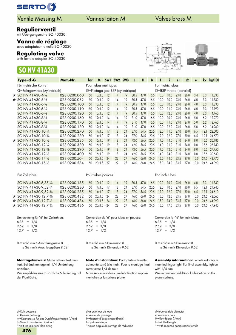
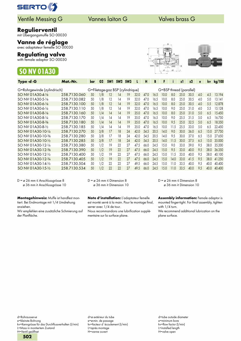
Regulierventilmit Übergangsmuffe SO 40030
Vanne de réglageavec adaptateur femelle SO 40030
Regulating valvewith female adaptor SO 40030
SO NV 41A30Type -d -G Mat.-Nr. bar M SW1 SW2 SW3 L H B F i z1 z2 e kv kg/100Für metrische Rohre Pour tubes métriques For metric tubesG=Rohrgewinde (zylindrisch) G=Filetage-gaz BSP (cylindrique) G=BSP thread (parallel)
SO NV 41A30-4-1/8 028.0200.060 50 10x1.0 12 14 19 30.5 47.0 16.5 10.0 10.0 23.0 26.0 3.4 3.3 11.330 SO NV 41A30-5-1/8 028.0200.082 50 10x1.0 12 14 19 30.5 47.0 16.5 10.0 10.0 23.0 26.0 4.0 3.3 11.330 SO NV 41A30-6-1/8 028.0200.100 50 10x1.0 12 14 19 30.5 47.0 16.5 10.0 10.0 23.0 26.0 4.0 3.3 11.330 SO NV 41A30-6-1/4 028.0200.110 50 10x1.0 12 14 19 30.5 47.0 16.5 10.0 11.0 23.0 26.0 4.0 3.3 12.190 SO NV 41A30-6-3/8 028.0200.120 50 10x1.0 12 14 19 30.5 47.0 16.5 10.0 12.0 23.0 26.0 4.0 3.3 14.460 SO NV 41A30-8-1/8 028.0200.160 50 12x1.0 14 14 19 31.0 47.0 16.5 10.0 10.0 23.0 26.0 5.0 6.2 12.970 SO NV 41A30-8-1/4 028.0200.170 50 12x1.0 14 14 19 31.0 47.0 16.5 10.0 11.0 23.0 27.0 5.0 6.2 12.760 SO NV 41A30-8-3/8 028.0200.180 50 12x1.0 14 14 19 31.0 47.0 16.5 10.0 12.0 23.0 26.0 5.0 6.2 14.960 SO NV 41A30-10-1/4 028.0200.270 50 14x1.0 17 18 24 37.0 54.5 20.5 12.0 11.0 27.0 30.0 6.5 12.1 22.000 SO NV 41A30-10-3/8 028.0200.280 50 14x1.0 17 18 24 37.0 54.5 20.5 12.0 12.0 27.0 30.0 6.5 12.1 24.670
SO NV 41A30-10-1/2 028.0200.285 50 16x1.0 19 18 24 42.0 56.5 20.5 14.0 14.0 31.0 34.0 8.0 16.6 26.186 SO NV 41A30-12-1/4 028.0200.380 50 16x1.0 19 18 24 42.0 56.5 20.5 14.0 11.0 31.0 34.0 8.0 16.6 26.140 SO NV 41A30-12-3/8 028.0200.390 50 16x1.0 19 18 24 42.0 56.5 20.5 14.0 12.0 31.0 34.0 8.0 16.6 27.450 SO NV 41A30-12-1/2 028.0200.400 50 16x1.0 19 18 24 42.0 56.5 20.5 14.0 14.0 31.0 34.0 8.0 16.6 30.630 SO NV 41A30-14-1/2 028.0200.504 50 20x1.5 24 22 27 46.0 66.0 24.5 15.0 14.0 33.5 37.0 10.0 24.6 43.770 SO NV 41A30-15-1/2 028.0200.534 50 20x1.5 27 22 27 46.0 66.0 24.5 15.0 14.0 33.5 37.0 10.0 24.6 44.090
Für Zollrohre Pour tubes pouces For inch tubes
SO NV 41A30-6,35-1/8 028.0200.135 50 10x1.0 12 14 19 30.5 47.0 16.5 10.0 10.0 23.0 26.0 4.0 3.3 11.340 SO NV 41A30-9,52-1/4 028.0200.230 50 14x1.0 17 18 24 37.0 54.5 20.5 12.0 10.0 27.0 30.0 6.5 12.1 21.940 SO NV 41A30-9,52-3/8 028.0200.235 50 14x1.0 17 18 24 37.0 54.5 20.5 12.0 12.0 27.0 30.0 6.5 12.1 24.610
SO NV 41A30-12,7-3/8 028.0200.432 50 20x1.5 24 22 27 46.0 66.0 24.5 15.0 12.0 33.5 37.0 10.0 24.6 42.060 SO NV 41A30-12,7-1/2 028.0200.434 50 20x1.5 24 22 27 46.0 66.0 24.5 15.0 14.0 33.5 37.0 10.0 24.6 44.090 SO NV 41A30-12,7-3/4 028.0200.436 50 20x1.5 24 22 27 46.0 66.0 24.5 15.0 17.0 33.5 37.0 10.0 24.6 47.940
Umrechnung für "d" bei Zollrohren:6,35 = 1/49,52 = 3/812,7 = 1/2
Conversion de "d" pour tubes en pouces:6,35 = 1/49,52 = 3/812,7 = 1/2
Conversion for "d" for inch tubes:6,35 = 1/49,52 = 3/812,7 = 1/2
D = ø 26 mm ≤ Anschlussgrösse 8 ø 36 mm ≥ Anschlussgrösse 9,52
D = ø 26 mm ≤ Dimension 8 ø 36 mm ≥ Dimension 9,52
D = ø 26 mm ≤ Dimension 8 ø 36 mm ≥ Dimension 9,52
Montagehinweis: Muffe ist handfest mon-tiert. Bei Endmontage mit 1/4 Umdrehung anziehen.Wir empfehlen eine zusätzliche Schmierung auf der Planfläche.
Note d’installation: L’adaptateur femelle est monté serré à la main. Pour le montage final, serrer avec 1/4 de tour.Nous recommandons une lubrification supplé-mentaire sur la surface plane.
Assembly information: Female adaptor is mounted finger-tight. For final assembly, tighten with 1/4 turn.We recommend additional lubrication on the plane surface.
Ventile Messing M Vannes laiton M Valves brass M
d=Rohraussen-øe=kleinste Bohrungkv=Kenngrösse für das Durchflussverhalten (l/min)L=Mass in montiertem Zustand*=mit reduziertem Klemmring
d=ø extérieur du tubee=ø-min. de passagekv=facteur d’écoulement (l/min)L=après montage*=avec bague de serrage de réduction
d=tube outside diametere=minimum borekv=flow factor (l/min)L=installed length*=with reduced compression ferrule
476
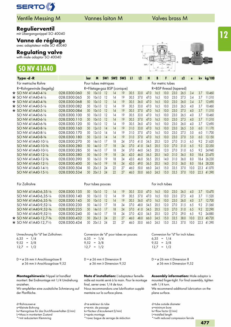
Regulierventilmit Übergangsnippel SO 40040
Vanne de réglageavec adaptateur mâle SO 40040
Regulating valvewith male adaptor SO 40040
SO NV 41A40Type -d -R bar M SW1 SW2 SW3 L1 L2 H B F z1 z2 e kv kg/100Für metrische Rohre Pour tubes métriques For metric tubesR=Rohrgewinde (kegelig) R=Filetage-gaz BSP (conique) R=BSP thread (tapered)
SO NV 41A40-4-1/8 028.0300.060 50 10x1.0 12 14 19 30.5 33.0 47.0 16.5 10.0 23.0 26.5 3.4 3.7 10.460 SO NV 41A40-4-1/4 028.0300.065 50 10x1.0 12 14 19 30.5 37.0 47.0 16.5 10.0 23.0 27.5 3.4 3.7 11.510 SO NV 41A40-4-3/8 028.0300.068 50 10x1.0 12 14 19 30.5 36.0 47.0 16.5 10.0 23.0 26.0 3.4 3.7 12.690 SO NV 41A40-5-1/8 028.0300.082 50 10x1.0 12 14 19 30.5 33.0 47.0 16.5 10.0 23.0 26.5 4.0 3.7 10.460 SO NV 41A40-5-1/4 028.0300.084 50 10x1.0 12 14 19 30.5 37.0 47.0 16.5 10.0 23.0 27.5 4.0 3.7 11.510 SO NV 41A40-6-1/8 028.0300.100 50 10x1.0 12 14 19 30.5 33.0 47.0 16.5 10.0 23.0 26.5 4.0 3.7 10.460 SO NV 41A40-6-1/4 028.0300.110 50 10x1.0 12 14 19 30.5 37.0 47.0 16.5 10.0 23.0 27.5 4.0 3.7 11.510 SO NV 41A40-6-3/8 028.0300.120 50 10x1.0 12 14 19 30.5 36.0 47.0 16.5 10.0 23.0 26.0 4.0 3.7 12.690 SO NV 41A40-8-1/8 028.0300.160 50 12x1.0 14 14 19 31.0 33.0 47.0 16.5 10.0 23.0 26.5 5.0 6.0 11.170 SO NV 41A40-8-1/4 028.0300.170 50 12x1.0 14 14 19 31.0 37.0 47.0 16.5 10.0 23.0 27.5 5.0 6.0 11.700 SO NV 41A40-8-3/8 028.0300.180 50 12x1.0 14 14 19 31.0 37.0 47.0 16.5 10.0 23.0 27.0 5.0 6.0 13.150 SO NV 41A40-10-1/4 028.0300.270 50 14x1.0 17 18 24 37.0 41.0 54.5 20.5 12.0 27.0 31.5 6.5 9.2 21.620 SO NV 41A40-10-3/8 028.0300.280 50 14x1.0 17 18 24 37.0 41.0 54.5 20.5 12.0 27.0 31.0 6.5 9.2 22.350 SO NV 41A40-10-1/2 028.0300.285 50 14x1.0 17 18 24 37.0 44.0 54.5 20.5 12.0 27.0 31.0 6.5 9.2 24.940 SO NV 41A40-12-1/4 028.0300.380 50 16x1.0 19 18 24 42.0 46.0 56.5 20.5 14.0 31.0 36.5 8.0 18.4 25.470 SO NV 41A40-12-3/8 028.0300.390 50 16x1.0 19 18 24 42.0 46.0 56.5 20.5 14.0 31.0 36.0 8.0 18.4 26.230 SO NV 41A40-12-1/2 028.0300.400 50 16x1.0 19 18 24 42.0 49.0 56.5 20.5 14.0 31.0 36.0 8.0 18.4 28.200 SO NV 41A40-14-1/2 028.0300.504 50 20x1.5 24 22 27 46.0 50.0 66.0 24.5 15.0 33.5 37.0 10.0 22.3 41.070 SO NV 41A40-15-1/2 028.0300.534 50 20x1.5 24 22 27 46.0 50.0 66.0 24.5 15.0 33.5 37.0 10.0 22.3 41.390
Für Zollrohre Pour tubes pouces For inch tubes
SO NV 41A40-6,35-1/8 028.0300.135 50 10x1.0 12 14 19 30.5 33.0 47.0 16.5 10.0 23.0 26.5 4.0 3.7 10.470 SO NV 41A40-6,35-1/4 028.0300.140 50 10x1.0 12 14 19 30.5 37.0 47.0 16.5 10.0 23.0 27.5 4.0 3.7 11.520 SO NV 41A40-6,35-3/8 028.0300.145 50 10x1.0 12 14 19 30.5 36.0 47.0 16.5 10.0 23.0 26.0 4.0 3.7 12.700 SO NV 41A40-9,52-1/4 028.0300.230 50 14x1.0 17 18 24 37.0 48.0 54.5 20.5 12.0 27.0 31.5 6.5 9.2 21.560 SO NV 41A40-9,52-3/8 028.0300.235 50 14x1.0 17 18 24 37.0 41.0 54.5 20.5 12.0 27.0 31.0 6.5 9.2 22.290 SO NV 41A40-9,52-1/2 028.0300.240 50 14x1.0 17 18 24 37.0 42.0 54.5 20.5 12.0 27.0 29.0 6.5 9.2 24.880
SO NV 41A40-12,7-3/8 028.0300.432 50 20x1.5 24 22 27 46.0 48.0 66.0 24.5 15.0 33.5 38.0 10.0 22.3 40.720 SO NV 41A40-12,7-1/2 028.0300.434 50 20x1.5 24 22 27 46.0 50.0 66.0 24.5 15.0 33.5 37.0 10.0 22.3 41.390
Umrechnung für "d" bei Zollrohren:6,35 = 1/49,52 = 3/812,7 = 1/2
Conversion de "d" pour tubes en pouces:6,35 = 1/49,52 = 3/812,7 = 1/2
Conversion for "d" for inch tubes:6,35 = 1/49,52 = 3/812,7 = 1/2
D = ø 26 mm ≤ Anschlussgrösse 8 ø 36 mm ≥ Anschlussgrösse 9,52
D = ø 26 mm ≤ Dimension 8 ø 36 mm ≥ Dimension 9,52
D = ø 26 mm ≤ Dimension 8 ø 36 mm ≥ Dimension 9,52
Montagehinweis: Nippel ist handfest montiert. Bei Endmontage mit 1/4 Umdrehung anziehen.Wir empfehlen eine zusätzliche Schmierung auf der Planfläche.
Note d’installation: L’adaptateur femelle-mâle est monté serré à la main. Pour le montage final, serrer avec 1/4 de tour.Nous recommandons une lubrification supplé-mentaire sur la surface plane.
Assembly information: Male adaptor is mounted finger-tight. For final assembly, tighten with 1/4 turn.We recommend additional lubrication on the plane surface.
Ventile Messing M Vannes laiton M Valves brass M
d=Rohraussen-øe=kleinste Bohrungkv=Kenngrösse für das Durchflussverhalten (l/min)L=Mass in montiertem Zustand*=mit reduziertem Klemmring
d=ø extérieur du tubee=ø-min. de passagekv=facteur d’écoulement (l/min)L=après montage*=avec bague de serrage de réduction
d=tube outside diametere=minimum borekv=flow factor (l/min)L=installed length*=with reduced compression ferrule
477
12
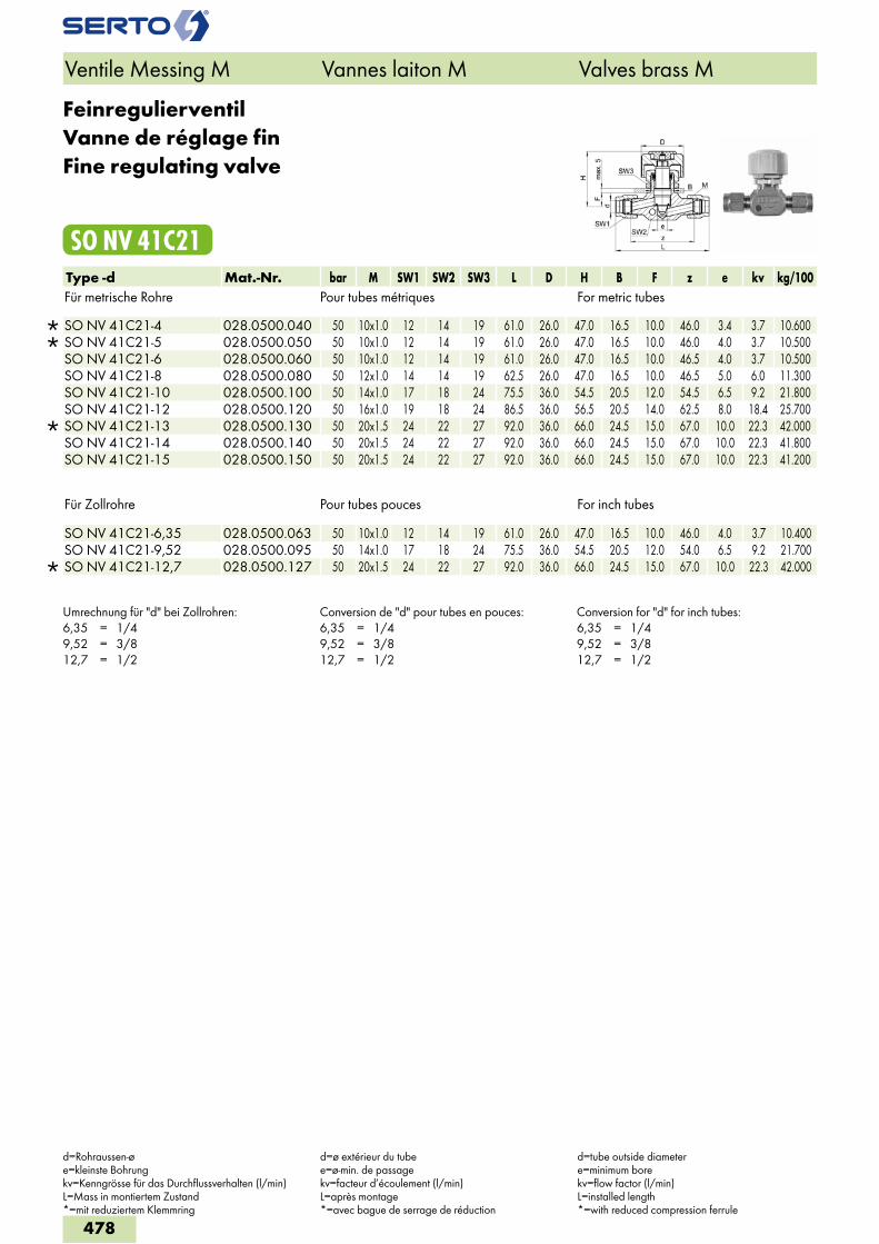
FeinregulierventilVanne de réglage finFine regulating valve
SO NV 41C21Type -d Mat.-Nr. bar M SW1 SW2 SW3 L D H B F z e kv kg/100Für metrische Rohre Pour tubes métriques For metric tubes
SO NV 41C21-4 028.0500.040 50 10x1.0 12 14 19 61.0 26.0 47.0 16.5 10.0 46.0 3.4 3.7 10.600 SO NV 41C21-5 028.0500.050 50 10x1.0 12 14 19 61.0 26.0 47.0 16.5 10.0 46.0 4.0 3.7 10.500 SO NV 41C21-6 028.0500.060 50 10x1.0 12 14 19 61.0 26.0 47.0 16.5 10.0 46.5 4.0 3.7 10.500 SO NV 41C21-8 028.0500.080 50 12x1.0 14 14 19 62.5 26.0 47.0 16.5 10.0 46.5 5.0 6.0 11.300 SO NV 41C21-10 028.0500.100 50 14x1.0 17 18 24 75.5 36.0 54.5 20.5 12.0 54.5 6.5 9.2 21.800 SO NV 41C21-12 028.0500.120 50 16x1.0 19 18 24 86.5 36.0 56.5 20.5 14.0 62.5 8.0 18.4 25.700
SO NV 41C21-13 028.0500.130 50 20x1.5 24 22 27 92.0 36.0 66.0 24.5 15.0 67.0 10.0 22.3 42.000 SO NV 41C21-14 028.0500.140 50 20x1.5 24 22 27 92.0 36.0 66.0 24.5 15.0 67.0 10.0 22.3 41.800 SO NV 41C21-15 028.0500.150 50 20x1.5 24 22 27 92.0 36.0 66.0 24.5 15.0 67.0 10.0 22.3 41.200
Für Zollrohre Pour tubes pouces For inch tubes
SO NV 41C21-6,35 028.0500.063 50 10x1.0 12 14 19 61.0 26.0 47.0 16.5 10.0 46.0 4.0 3.7 10.400 SO NV 41C21-9,52 028.0500.095 50 14x1.0 17 18 24 75.5 36.0 54.5 20.5 12.0 54.0 6.5 9.2 21.700
SO NV 41C21-12,7 028.0500.127 50 20x1.5 24 22 27 92.0 36.0 66.0 24.5 15.0 67.0 10.0 22.3 42.000
Umrechnung für "d" bei Zollrohren:6,35 = 1/49,52 = 3/812,7 = 1/2
Conversion de "d" pour tubes en pouces:6,35 = 1/49,52 = 3/812,7 = 1/2
Conversion for "d" for inch tubes:6,35 = 1/49,52 = 3/812,7 = 1/2
Ventile Messing M Vannes laiton M Valves brass M
d=Rohraussen-øe=kleinste Bohrungkv=Kenngrösse für das Durchflussverhalten (l/min)L=Mass in montiertem Zustand*=mit reduziertem Klemmring
d=ø extérieur du tubee=ø-min. de passagekv=facteur d’écoulement (l/min)L=après montage*=avec bague de serrage de réduction
d=tube outside diametere=minimum borekv=flow factor (l/min)L=installed length*=with reduced compression ferrule
478
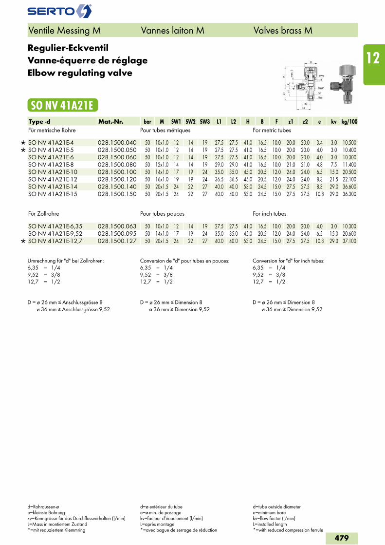
Regulier-EckventilVanne-équerre de réglageElbow regulating valve
SO NV 41A21EType -d Mat.-Nr. bar M SW1 SW2 SW3 L1 L2 H B F z1 z2 e kv kg/100Für metrische Rohre Pour tubes métriques For metric tubes
SO NV 41A21E-4 028.1500.040 50 10x1.0 12 14 19 27.5 27.5 41.0 16.5 10.0 20.0 20.0 3.4 3.0 10.500 SO NV 41A21E-5 028.1500.050 50 10x1.0 12 14 19 27.5 27.5 41.0 16.5 10.0 20.0 20.0 4.0 3.0 10.400 SO NV 41A21E-6 028.1500.060 50 10x1.0 12 14 19 27.5 27.5 41.0 16.5 10.0 20.0 20.0 4.0 3.0 10.300 SO NV 41A21E-8 028.1500.080 50 12x1.0 14 14 19 29.0 29.0 41.0 16.5 10.0 21.0 21.0 4.8 7.5 11.400 SO NV 41A21E-10 028.1500.100 50 14x1.0 17 19 24 35.0 35.0 45.0 20.5 12.0 24.0 24.0 6.5 15.0 20.500 SO NV 41A21E-12 028.1500.120 50 16x1.0 19 19 24 36.5 36.5 45.0 20.5 12.0 24.0 24.0 8.3 21.5 22.100 SO NV 41A21E-14 028.1500.140 50 20x1.5 24 22 27 40.0 40.0 53.0 24.5 15.0 27.5 27.5 8.3 29.0 36.600 SO NV 41A21E-15 028.1500.150 50 20x1.5 24 22 27 40.0 40.0 53.0 24.5 15.0 27.5 27.5 10.8 29.0 36.300
Für Zollrohre Pour tubes pouces For inch tubes
SO NV 41A21E-6,35 028.1500.063 50 10x1.0 12 14 19 27.5 27.5 41.0 16.5 10.0 20.0 20.0 4.0 3.0 10.300 SO NV 41A21E-9,52 028.1500.095 50 14x1.0 17 19 24 35.0 35.0 45.0 20.5 12.0 24.0 24.0 6.5 15.0 20.600
SO NV 41A21E-12,7 028.1500.127 50 20x1.5 24 22 27 40.0 40.0 53.0 24.5 15.0 27.5 27.5 10.8 29.0 37.100
Umrechnung für "d" bei Zollrohren:6,35 = 1/49,52 = 3/812,7 = 1/2
Conversion de "d" pour tubes en pouces:6,35 = 1/49,52 = 3/812,7 = 1/2
Conversion for "d" for inch tubes:6,35 = 1/49,52 = 3/812,7 = 1/2
D = ø 26 mm ≤ Anschlussgrösse 8 ø 36 mm ≥ Anschlussgrösse 9,52
D = ø 26 mm ≤ Dimension 8 ø 36 mm ≥ Dimension 9,52
D = ø 26 mm ≤ Dimension 8 ø 36 mm ≥ Dimension 9,52
Ventile Messing M Vannes laiton M Valves brass M
d=Rohraussen-øe=kleinste Bohrungkv=Kenngrösse für das Durchflussverhalten (l/min)L=Mass in montiertem Zustand*=mit reduziertem Klemmring
d=ø extérieur du tubee=ø-min. de passagekv=facteur d’écoulement (l/min)L=après montage*=avec bague de serrage de réduction
d=tube outside diametere=minimum borekv=flow factor (l/min)L=installed length*=with reduced compression ferrule
479
12
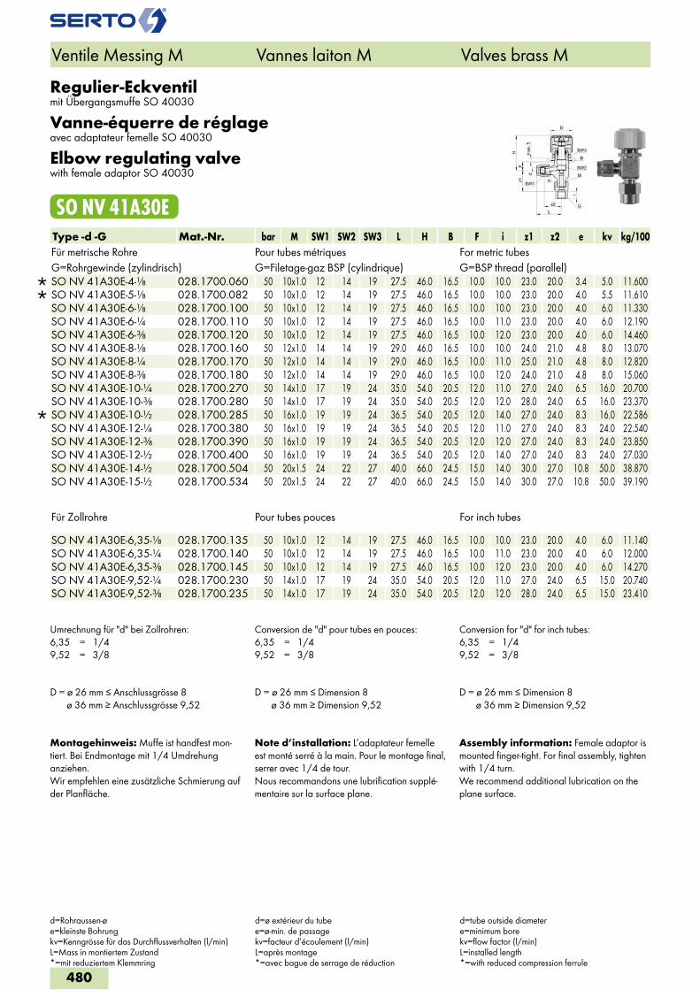
Regulier-Eckventilmit Übergangsmuffe SO 40030
Vanne-équerre de réglageavec adaptateur femelle SO 40030
Elbow regulating valvewith female adaptor SO 40030
SO NV 41A30EType -d -G Mat.-Nr. bar M SW1 SW2 SW3 L H B F i z1 z2 e kv kg/100Für metrische Rohre Pour tubes métriques For metric tubesG=Rohrgewinde (zylindrisch) G=Filetage-gaz BSP (cylindrique) G=BSP thread (parallel)
SO NV 41A30E-4-1/8 028.1700.060 50 10x1.0 12 14 19 27.5 46.0 16.5 10.0 10.0 23.0 20.0 3.4 5.0 11.600 SO NV 41A30E-5-1/8 028.1700.082 50 10x1.0 12 14 19 27.5 46.0 16.5 10.0 10.0 23.0 20.0 4.0 5.5 11.610 SO NV 41A30E-6-1/8 028.1700.100 50 10x1.0 12 14 19 27.5 46.0 16.5 10.0 10.0 23.0 20.0 4.0 6.0 11.330 SO NV 41A30E-6-1/4 028.1700.110 50 10x1.0 12 14 19 27.5 46.0 16.5 10.0 11.0 23.0 20.0 4.0 6.0 12.190 SO NV 41A30E-6-3/8 028.1700.120 50 10x1.0 12 14 19 27.5 46.0 16.5 10.0 12.0 23.0 20.0 4.0 6.0 14.460 SO NV 41A30E-8-1/8 028.1700.160 50 12x1.0 14 14 19 29.0 46.0 16.5 10.0 10.0 24.0 21.0 4.8 8.0 13.070 SO NV 41A30E-8-1/4 028.1700.170 50 12x1.0 14 14 19 29.0 46.0 16.5 10.0 11.0 25.0 21.0 4.8 8.0 12.820 SO NV 41A30E-8-3/8 028.1700.180 50 12x1.0 14 14 19 29.0 46.0 16.5 10.0 12.0 24.0 21.0 4.8 8.0 15.060 SO NV 41A30E-10-1/4 028.1700.270 50 14x1.0 17 19 24 35.0 54.0 20.5 12.0 11.0 27.0 24.0 6.5 16.0 20.700 SO NV 41A30E-10-3/8 028.1700.280 50 14x1.0 17 19 24 35.0 54.0 20.5 12.0 12.0 28.0 24.0 6.5 16.0 23.370
SO NV 41A30E-10-1/2 028.1700.285 50 16x1.0 19 19 24 36.5 54.0 20.5 12.0 14.0 27.0 24.0 8.3 16.0 22.586 SO NV 41A30E-12-1/4 028.1700.380 50 16x1.0 19 19 24 36.5 54.0 20.5 12.0 11.0 27.0 24.0 8.3 24.0 22.540 SO NV 41A30E-12-3/8 028.1700.390 50 16x1.0 19 19 24 36.5 54.0 20.5 12.0 12.0 27.0 24.0 8.3 24.0 23.850 SO NV 41A30E-12-1/2 028.1700.400 50 16x1.0 19 19 24 36.5 54.0 20.5 12.0 14.0 27.0 24.0 8.3 24.0 27.030 SO NV 41A30E-14-1/2 028.1700.504 50 20x1.5 24 22 27 40.0 66.0 24.5 15.0 14.0 30.0 27.0 10.8 50.0 38.870 SO NV 41A30E-15-1/2 028.1700.534 50 20x1.5 24 22 27 40.0 66.0 24.5 15.0 14.0 30.0 27.0 10.8 50.0 39.190
Für Zollrohre Pour tubes pouces For inch tubes SO NV 41A30E-6,35-1/8 028.1700.135 50 10x1.0 12 14 19 27.5 46.0 16.5 10.0 10.0 23.0 20.0 4.0 6.0 11.140SO NV 41A30E-6,35-1/4 028.1700.140 50 10x1.0 12 14 19 27.5 46.0 16.5 10.0 11.0 23.0 20.0 4.0 6.0 12.000SO NV 41A30E-6,35-3/8 028.1700.145 50 10x1.0 12 14 19 27.5 46.0 16.5 10.0 12.0 23.0 20.0 4.0 6.0 14.270SO NV 41A30E-9,52-1/4 028.1700.230 50 14x1.0 17 19 24 35.0 54.0 20.5 12.0 11.0 27.0 24.0 6.5 15.0 20.740SO NV 41A30E-9,52-3/8 028.1700.235 50 14x1.0 17 19 24 35.0 54.0 20.5 12.0 12.0 28.0 24.0 6.5 15.0 23.410
Umrechnung für "d" bei Zollrohren:6,35 = 1/49,52 = 3/8
Conversion de "d" pour tubes en pouces:6,35 = 1/49,52 = 3/8
Conversion for "d" for inch tubes:6,35 = 1/49,52 = 3/8
D = ø 26 mm ≤ Anschlussgrösse 8 ø 36 mm ≥ Anschlussgrösse 9,52
D = ø 26 mm ≤ Dimension 8 ø 36 mm ≥ Dimension 9,52
D = ø 26 mm ≤ Dimension 8 ø 36 mm ≥ Dimension 9,52
Montagehinweis: Muffe ist handfest mon-tiert. Bei Endmontage mit 1/4 Umdrehung anziehen.Wir empfehlen eine zusätzliche Schmierung auf der Planfläche.
Note d’installation: L’adaptateur femelle est monté serré à la main. Pour le montage final, serrer avec 1/4 de tour.Nous recommandons une lubrification supplé-mentaire sur la surface plane.
Assembly information: Female adaptor is mounted finger-tight. For final assembly, tighten with 1/4 turn.We recommend additional lubrication on the plane surface.
Ventile Messing M Vannes laiton M Valves brass M
d=Rohraussen-øe=kleinste Bohrungkv=Kenngrösse für das Durchflussverhalten (l/min)L=Mass in montiertem Zustand*=mit reduziertem Klemmring
d=ø extérieur du tubee=ø-min. de passagekv=facteur d’écoulement (l/min)L=après montage*=avec bague de serrage de réduction
d=tube outside diametere=minimum borekv=flow factor (l/min)L=installed length*=with reduced compression ferrule
480
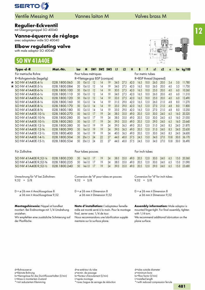
Regulier-Eckventilmit Übergangsnippel SO 40040
Vanne-équerre de réglageavec adaptateur mâle SO 40040
Elbow regulating valvewith male adaptor SO 40040
SO NV 41A40EType -d -R Mat.-Nr. bar M SW1 SW2 SW3 L1 L2 H B F z1 z2 e kv kg/100Für metrische Rohre Pour tubes métriques For metric tubesR=Rohrgewinde (kegelig) R=Filetage-gaz BSP (conique) R=BSP thread (tapered)
SO NV 41A40E-4-1/4 028.1800.065 50 10x1.0 12 14 19 34.0 27.5 42.0 16.5 10.0 26.0 20.0 3.4 5.0 11.780 SO NV 41A40E-5-1/4 028.1800.084 50 10x1.0 12 14 19 34.0 27.5 42.0 16.5 10.0 26.0 20.0 4.0 5.5 11.750 SO NV 41A40E-6-1/8 028.1800.100 50 10x1.0 12 14 19 30.0 27.5 42.0 16.5 10.0 25.0 20.0 4.0 6.0 10.260 SO NV 41A40E-6-1/4 028.1800.110 50 10x1.0 12 14 19 34.0 27.5 42.0 16.5 10.0 26.0 20.0 4.0 6.0 11.310 SO NV 41A40E-6-3/8 028.1800.120 50 10x1.0 12 14 19 33.0 27.5 42.0 16.5 10.0 25.0 20.0 4.0 6.0 12.490 SO NV 41A40E-8-1/8 028.1800.160 50 12x1.0 14 14 19 31.0 29.0 42.0 16.5 12.0 26.0 21.0 4.8 8.0 11.270 SO NV 41A40E-8-1/4 028.1800.170 50 12x1.0 14 14 19 35.0 29.0 42.0 16.5 12.0 27.0 21.0 4.8 8.0 11.800 SO NV 41A40E-8-3/8 028.1800.180 50 12x1.0 14 14 19 35.0 29.0 42.0 16.5 12.0 27.0 21.0 4.8 8.0 13.250 SO NV 41A40E-10-1/4 028.1800.270 50 14x1.0 17 19 24 38.0 35.0 49.0 20.5 12.0 30.0 24.0 6.5 16.0 20.320 SO NV 41A40E-10-3/8 028.1800.280 50 14x1.0 17 19 24 38.0 35.0 49.0 20.5 12.0 30.0 24.0 6.5 16.0 21.050 SO NV 41A40E-10-1/2 028.1800.285 50 14x1.0 17 19 24 39.0 35.0 49.0 20.5 12.0 29.0 24.0 6.5 16.0 23.640 SO NV 41A40E-12-1/4 028.1800.380 50 16x1.0 19 19 24 39.0 36.5 49.0 20.5 12.0 31.0 24.0 8.3 24.0 21.870 SO NV 41A40E-12-3/8 028.1800.390 50 16x1.0 19 19 24 39.0 36.5 49.0 20.5 12.0 31.0 24.0 8.3 24.0 22.630 SO NV 41A40E-12-1/2 028.1800.400 50 16x1.0 19 19 24 40.0 36.5 49.0 20.5 12.0 30.0 24.0 8.3 24.0 24.600 SO NV 41A40E-14-1/2 028.1800.504 50 20x1.5 24 22 27 44.0 40.0 57.5 24.5 15.0 34.0 27.0 10.8 50.0 36.170 SO NV 41A40E-15-1/2 028.1800.534 50 20x1.5 24 22 27 44.0 40.0 57.5 24.5 15.0 34.0 27.0 10.8 50.0 36.490
Für Zollrohre Pour tubes pouces For inch tubes SO NV 41A40E-9,52-1/4 028.1800.230 50 14x1.0 17 19 24 38.0 35.0 49.0 20.5 12.0 30.0 24.0 6.5 15.0 20.360SO NV 41A40E-9,52-3/8 028.1800.235 50 14x1.0 17 19 24 38.0 35.0 49.0 20.5 12.0 30.0 24.0 6.5 15.0 21.090SO NV 41A40E-9,52-1/2 028.1800.240 50 14x1.0 17 19 24 39.0 35.0 49.0 20.5 12.0 29.0 24.0 6.5 15.0 23.680
Umrechnung für "d" bei Zollrohren:9,52 = 3/8
Conversion de "d" pour tubes en pouces:9,52 = 3/8
Conversion for "d" for inch tubes:9,52 = 3/8
D = ø 26 mm ≤ Anschlussgrösse 8 ø 36 mm ≥ Anschlussgrösse 9,52
D = ø 26 mm ≤ Dimension 8 ø 36 mm ≥ Dimension 9,52
D = ø 26 mm ≤ Dimension 8 ø 36 mm ≥ Dimension 9,52
Montagehinweis: Nippel ist handfest montiert. Bei Endmontage mit 1/4 Umdrehung anziehen.Wir empfehlen eine zusätzliche Schmierung auf der Planfläche.
Note d’installation: L’adaptateur femelle-mâle est monté serré à la main. Pour le montage final, serrer avec 1/4 de tour.Nous recommandons une lubrification supplé-mentaire sur la surface plane.
Assembly information: Male adaptor is mounted finger-tight. For final assembly, tighten with 1/4 turn.We recommend additional lubrication on the plane surface.
Ventile Messing M Vannes laiton M Valves brass M
d=Rohraussen-øe=kleinste Bohrungkv=Kenngrösse für das Durchflussverhalten (l/min)L=Mass in montiertem Zustand*=mit reduziertem Klemmring
d=ø extérieur du tubee=ø-min. de passagekv=facteur d’écoulement (l/min)L=après montage*=avec bague de serrage de réduction
d=tube outside diametere=minimum borekv=flow factor (l/min)L=installed length*=with reduced compression ferrule
481
12
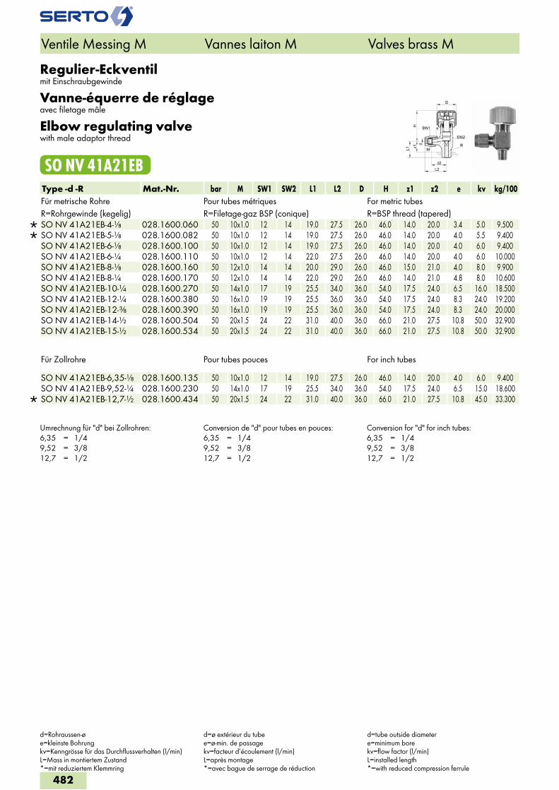
Regulier-Eckventilmit Einschraubgewinde
Vanne-équerre de réglageavec filetage mâle
Elbow regulating valvewith male adaptor thread
SO NV 41A21EBType -d -R Mat.-Nr. bar M SW1 SW2 L1 L2 D H z1 z2 e kv kg/100Für metrische Rohre Pour tubes métriques For metric tubesR=Rohrgewinde (kegelig) R=Filetage-gaz BSP (conique) R=BSP thread (tapered)
SO NV 41A21EB-4-1/8 028.1600.060 50 10x1.0 12 14 19.0 27.5 26.0 46.0 14.0 20.0 3.4 5.0 9.500 SO NV 41A21EB-5-1/8 028.1600.082 50 10x1.0 12 14 19.0 27.5 26.0 46.0 14.0 20.0 4.0 5.5 9.400 SO NV 41A21EB-6-1/8 028.1600.100 50 10x1.0 12 14 19.0 27.5 26.0 46.0 14.0 20.0 4.0 6.0 9.400 SO NV 41A21EB-6-1/4 028.1600.110 50 10x1.0 12 14 22.0 27.5 26.0 46.0 14.0 20.0 4.0 6.0 10.000 SO NV 41A21EB-8-1/8 028.1600.160 50 12x1.0 14 14 20.0 29.0 26.0 46.0 15.0 21.0 4.0 8.0 9.900 SO NV 41A21EB-8-1/4 028.1600.170 50 12x1.0 14 14 22.0 29.0 26.0 46.0 14.0 21.0 4.8 8.0 10.600 SO NV 41A21EB-10-1/4 028.1600.270 50 14x1.0 17 19 25.5 34.0 36.0 54.0 17.5 24.0 6.5 16.0 18.500 SO NV 41A21EB-12-1/4 028.1600.380 50 16x1.0 19 19 25.5 36.0 36.0 54.0 17.5 24.0 8.3 24.0 19.200 SO NV 41A21EB-12-3/8 028.1600.390 50 16x1.0 19 19 25.5 36.0 36.0 54.0 17.5 24.0 8.3 24.0 20.000 SO NV 41A21EB-14-1/2 028.1600.504 50 20x1.5 24 22 31.0 40.0 36.0 66.0 21.0 27.5 10.8 50.0 32.900 SO NV 41A21EB-15-1/2 028.1600.534 50 20x1.5 24 22 31.0 40.0 36.0 66.0 21.0 27.5 10.8 50.0 32.900
Für Zollrohre Pour tubes pouces For inch tubes
SO NV 41A21EB-6,35-1/8 028.1600.135 50 10x1.0 12 14 19.0 27.5 26.0 46.0 14.0 20.0 4.0 6.0 9.400 SO NV 41A21EB-9,52-1/4 028.1600.230 50 14x1.0 17 19 25.5 34.0 36.0 54.0 17.5 24.0 6.5 15.0 18.600
SO NV 41A21EB-12,7-1/2 028.1600.434 50 20x1.5 24 22 31.0 40.0 36.0 66.0 21.0 27.5 10.8 45.0 33.300
Umrechnung für "d" bei Zollrohren:6,35 = 1/49,52 = 3/812,7 = 1/2
Conversion de "d" pour tubes en pouces:6,35 = 1/49,52 = 3/812,7 = 1/2
Conversion for "d" for inch tubes:6,35 = 1/49,52 = 3/812,7 = 1/2
Ventile Messing M Vannes laiton M Valves brass M
d=Rohraussen-øe=kleinste Bohrungkv=Kenngrösse für das Durchflussverhalten (l/min)L=Mass in montiertem Zustand*=mit reduziertem Klemmring
d=ø extérieur du tubee=ø-min. de passagekv=facteur d’écoulement (l/min)L=après montage*=avec bague de serrage de réduction
d=tube outside diametere=minimum borekv=flow factor (l/min)L=installed length*=with reduced compression ferrule
482
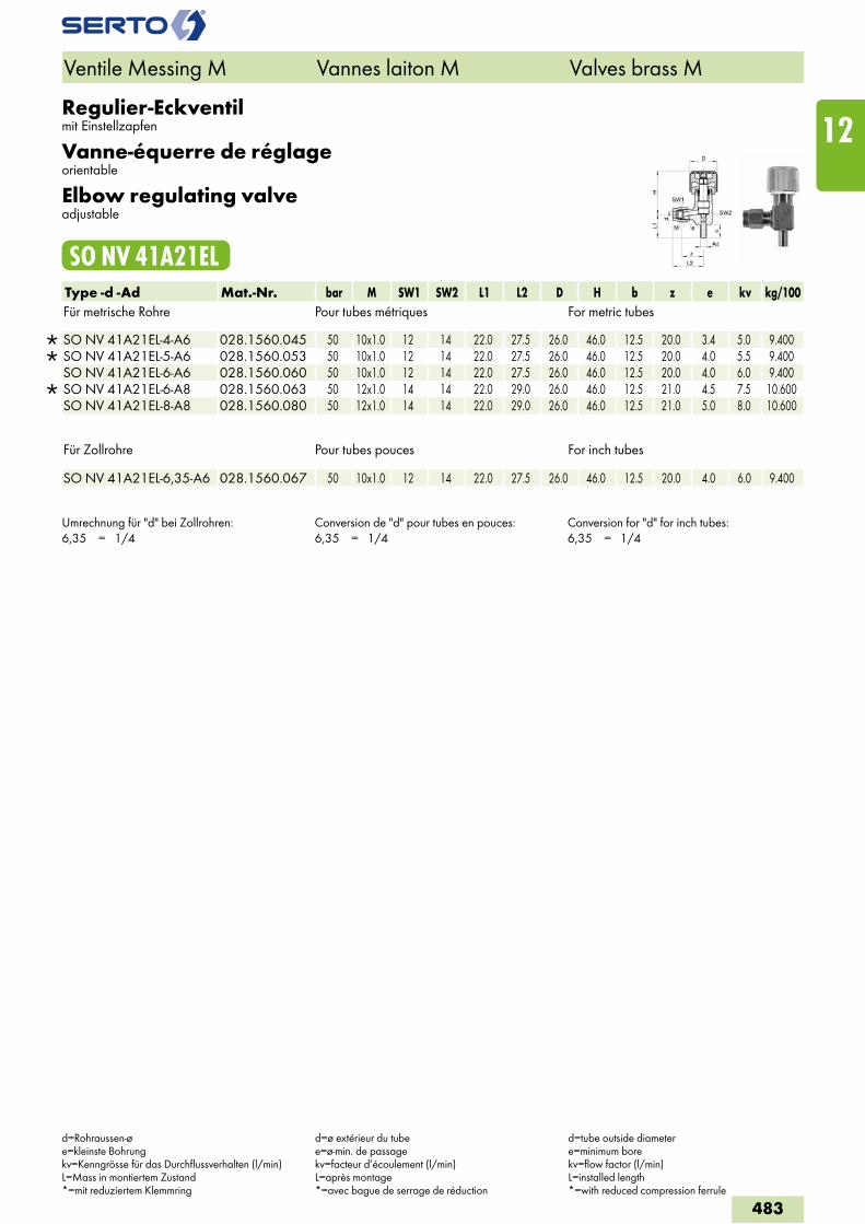
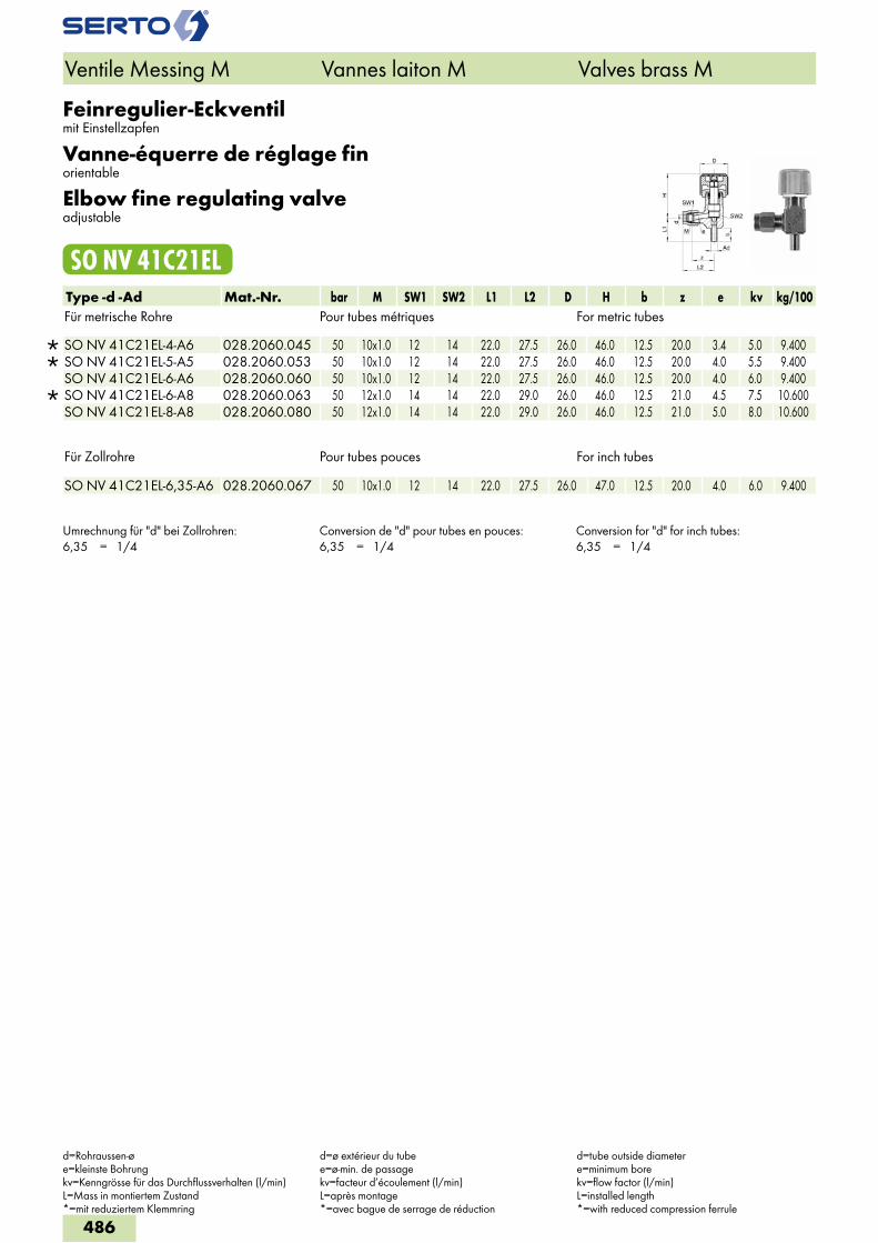
Regulier-Eckventilmit Einstellzapfen
Vanne-équerre de réglageorientable
Elbow regulating valveadjustable
SO NV 41A21ELType -d -Ad Mat.-Nr. bar M SW1 SW2 L1 L2 D H b z e kv kg/100Für metrische Rohre Pour tubes métriques For metric tubes
SO NV 41A21EL-4-A6 028.1560.045 50 10x1.0 12 14 22.0 27.5 26.0 46.0 12.5 20.0 3.4 5.0 9.400 SO NV 41A21EL-5-A6 028.1560.053 50 10x1.0 12 14 22.0 27.5 26.0 46.0 12.5 20.0 4.0 5.5 9.400 SO NV 41A21EL-6-A6 028.1560.060 50 10x1.0 12 14 22.0 27.5 26.0 46.0 12.5 20.0 4.0 6.0 9.400
SO NV 41A21EL-6-A8 028.1560.063 50 12x1.0 14 14 22.0 29.0 26.0 46.0 12.5 21.0 4.5 7.5 10.600 SO NV 41A21EL-8-A8 028.1560.080 50 12x1.0 14 14 22.0 29.0 26.0 46.0 12.5 21.0 5.0 8.0 10.600
Für Zollrohre Pour tubes pouces For inch tubes
SO NV 41A21EL-6,35-A6 028.1560.067 50 10x1.0 12 14 22.0 27.5 26.0 46.0 12.5 20.0 4.0 6.0 9.400
Umrechnung für "d" bei Zollrohren:6,35 = 1/4
Conversion de "d" pour tubes en pouces:6,35 = 1/4
Conversion for "d" for inch tubes:6,35 = 1/4
Ventile Messing M Vannes laiton M Valves brass M
d=Rohraussen-øe=kleinste Bohrungkv=Kenngrösse für das Durchflussverhalten (l/min)L=Mass in montiertem Zustand*=mit reduziertem Klemmring
d=ø extérieur du tubee=ø-min. de passagekv=facteur d’écoulement (l/min)L=après montage*=avec bague de serrage de réduction
d=tube outside diametere=minimum borekv=flow factor (l/min)L=installed length*=with reduced compression ferrule
483
12
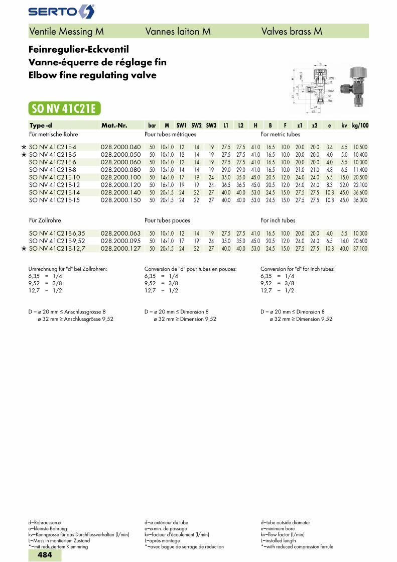
Feinregulier-EckventilVanne-équerre de réglage finElbow fine regulating valve
SO NV 41C21EType -d Mat.-Nr. bar M SW1 SW2 SW3 L1 L2 H B F z1 z2 e kv kg/100Für metrische Rohre Pour tubes métriques For metric tubes
SO NV 41C21E-4 028.2000.040 50 10x1.0 12 14 19 27.5 27.5 41.0 16.5 10.0 20.0 20.0 3.4 4.5 10.500 SO NV 41C21E-5 028.2000.050 50 10x1.0 12 14 19 27.5 27.5 41.0 16.5 10.0 20.0 20.0 4.0 5.0 10.400 SO NV 41C21E-6 028.2000.060 50 10x1.0 12 14 19 27.5 27.5 41.0 16.5 10.0 20.0 20.0 4.0 5.5 10.300 SO NV 41C21E-8 028.2000.080 50 12x1.0 14 14 19 29.0 29.0 41.0 16.5 10.0 21.0 21.0 4.8 6.5 11.400 SO NV 41C21E-10 028.2000.100 50 14x1.0 17 19 24 35.0 35.0 45.0 20.5 12.0 24.0 24.0 6.5 15.0 20.500 SO NV 41C21E-12 028.2000.120 50 16x1.0 19 19 24 36.5 36.5 45.0 20.5 12.0 24.0 24.0 8.3 22.0 22.100 SO NV 41C21E-14 028.2000.140 50 20x1.5 24 22 27 40.0 40.0 53.0 24.5 15.0 27.5 27.5 10.8 45.0 36.600 SO NV 41C21E-15 028.2000.150 50 20x1.5 24 22 27 40.0 40.0 53.0 24.5 15.0 27.5 27.5 10.8 45.0 36.300
Für Zollrohre Pour tubes pouces For inch tubes
SO NV 41C21E-6,35 028.2000.063 50 10x1.0 12 14 19 27.5 27.5 41.0 16.5 10.0 20.0 20.0 4.0 5.5 10.300 SO NV 41C21E-9,52 028.2000.095 50 14x1.0 17 19 24 35.0 35.0 45.0 20.5 12.0 24.0 24.0 6.5 14.0 20.600
SO NV 41C21E-12,7 028.2000.127 50 20x1.5 24 22 27 40.0 40.0 53.0 24.5 15.0 27.5 27.5 10.8 40.0 37.100
Umrechnung für "d" bei Zollrohren:6,35 = 1/49,52 = 3/812,7 = 1/2
Conversion de "d" pour tubes en pouces:6,35 = 1/49,52 = 3/812,7 = 1/2
Conversion for "d" for inch tubes:6,35 = 1/49,52 = 3/812,7 = 1/2
D = ø 20 mm ≤ Anschlussgrösse 8 ø 32 mm ≥ Anschlussgrösse 9,52
D = ø 20 mm ≤ Dimension 8 ø 32 mm ≥ Dimension 9,52
D = ø 20 mm ≤ Dimension 8 ø 32 mm ≥ Dimension 9,52
Ventile Messing M Vannes laiton M Valves brass M
d=Rohraussen-øe=kleinste Bohrungkv=Kenngrösse für das Durchflussverhalten (l/min)L=Mass in montiertem Zustand*=mit reduziertem Klemmring
d=ø extérieur du tubee=ø-min. de passagekv=facteur d’écoulement (l/min)L=après montage*=avec bague de serrage de réduction
d=tube outside diametere=minimum borekv=flow factor (l/min)L=installed length*=with reduced compression ferrule
484
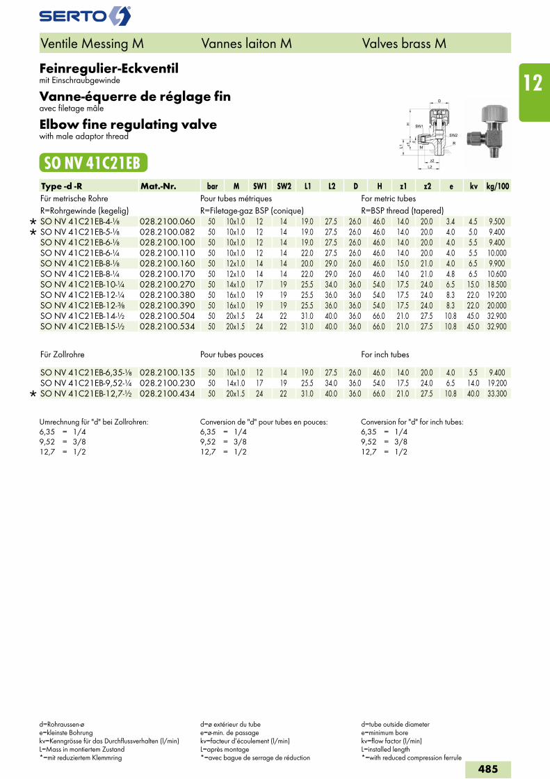
Feinregulier-Eckventilmit Einschraubgewinde
Vanne-équerre de réglage finavec filetage mâle
Elbow fine regulating valvewith male adaptor thread
SO NV 41C21EBType -d -R Mat.-Nr. bar M SW1 SW2 L1 L2 D H z1 z2 e kv kg/100Für metrische Rohre Pour tubes métriques For metric tubesR=Rohrgewinde (kegelig) R=Filetage-gaz BSP (conique) R=BSP thread (tapered)
SO NV 41C21EB-4-1/8 028.2100.060 50 10x1.0 12 14 19.0 27.5 26.0 46.0 14.0 20.0 3.4 4.5 9.500 SO NV 41C21EB-5-1/8 028.2100.082 50 10x1.0 12 14 19.0 27.5 26.0 46.0 14.0 20.0 4.0 5.0 9.400 SO NV 41C21EB-6-1/8 028.2100.100 50 10x1.0 12 14 19.0 27.5 26.0 46.0 14.0 20.0 4.0 5.5 9.400 SO NV 41C21EB-6-1/4 028.2100.110 50 10x1.0 12 14 22.0 27.5 26.0 46.0 14.0 20.0 4.0 5.5 10.000 SO NV 41C21EB-8-1/8 028.2100.160 50 12x1.0 14 14 20.0 29.0 26.0 46.0 15.0 21.0 4.0 6.5 9.900 SO NV 41C21EB-8-1/4 028.2100.170 50 12x1.0 14 14 22.0 29.0 26.0 46.0 14.0 21.0 4.8 6.5 10.600 SO NV 41C21EB-10-1/4 028.2100.270 50 14x1.0 17 19 25.5 34.0 36.0 54.0 17.5 24.0 6.5 15.0 18.500 SO NV 41C21EB-12-1/4 028.2100.380 50 16x1.0 19 19 25.5 36.0 36.0 54.0 17.5 24.0 8.3 22.0 19.200 SO NV 41C21EB-12-3/8 028.2100.390 50 16x1.0 19 19 25.5 36.0 36.0 54.0 17.5 24.0 8.3 22.0 20.000 SO NV 41C21EB-14-1/2 028.2100.504 50 20x1.5 24 22 31.0 40.0 36.0 66.0 21.0 27.5 10.8 45.0 32.900 SO NV 41C21EB-15-1/2 028.2100.534 50 20x1.5 24 22 31.0 40.0 36.0 66.0 21.0 27.5 10.8 45.0 32.900
Für Zollrohre Pour tubes pouces For inch tubes
SO NV 41C21EB-6,35-1/8 028.2100.135 50 10x1.0 12 14 19.0 27.5 26.0 46.0 14.0 20.0 4.0 5.5 9.400 SO NV 41C21EB-9,52-1/4 028.2100.230 50 14x1.0 17 19 25.5 34.0 36.0 54.0 17.5 24.0 6.5 14.0 19.200
SO NV 41C21EB-12,7-1/2 028.2100.434 50 20x1.5 24 22 31.0 40.0 36.0 66.0 21.0 27.5 10.8 40.0 33.300
Umrechnung für "d" bei Zollrohren:6,35 = 1/49,52 = 3/812,7 = 1/2
Conversion de "d" pour tubes en pouces:6,35 = 1/49,52 = 3/812,7 = 1/2
Conversion for "d" for inch tubes:6,35 = 1/49,52 = 3/812,7 = 1/2
Ventile Messing M Vannes laiton M Valves brass M
d=Rohraussen-øe=kleinste Bohrungkv=Kenngrösse für das Durchflussverhalten (l/min)L=Mass in montiertem Zustand*=mit reduziertem Klemmring
d=ø extérieur du tubee=ø-min. de passagekv=facteur d’écoulement (l/min)L=après montage*=avec bague de serrage de réduction
d=tube outside diametere=minimum borekv=flow factor (l/min)L=installed length*=with reduced compression ferrule
485
12
Feinregulier-Eckventilmit Einstellzapfen
Vanne-équerre de réglage finorientable
Elbow fine regulating valveadjustable
SO NV 41C21ELType -d -Ad Mat.-Nr. bar M SW1 SW2 L1 L2 D H b z e kv kg/100Für metrische Rohre Pour tubes métriques For metric tubes
SO NV 41C21EL-4-A6 028.2060.045 50 10x1.0 12 14 22.0 27.5 26.0 46.0 12.5 20.0 3.4 5.0 9.400 SO NV 41C21EL-5-A5 028.2060.053 50 10x1.0 12 14 22.0 27.5 26.0 46.0 12.5 20.0 4.0 5.5 9.400 SO NV 41C21EL-6-A6 028.2060.060 50 10x1.0 12 14 22.0 27.5 26.0 46.0 12.5 20.0 4.0 6.0 9.400
SO NV 41C21EL-6-A8 028.2060.063 50 12x1.0 14 14 22.0 29.0 26.0 46.0 12.5 21.0 4.5 7.5 10.600 SO NV 41C21EL-8-A8 028.2060.080 50 12x1.0 14 14 22.0 29.0 26.0 46.0 12.5 21.0 5.0 8.0 10.600
Für Zollrohre Pour tubes pouces For inch tubes
SO NV 41C21EL-6,35-A6 028.2060.067 50 10x1.0 12 14 22.0 27.5 26.0 47.0 12.5 20.0 4.0 6.0 9.400
Umrechnung für "d" bei Zollrohren:6,35 = 1/4
Conversion de "d" pour tubes en pouces:6,35 = 1/4
Conversion for "d" for inch tubes:6,35 = 1/4
Ventile Messing M Vannes laiton M Valves brass M
d=Rohraussen-øe=kleinste Bohrungkv=Kenngrösse für das Durchflussverhalten (l/min)L=Mass in montiertem Zustand*=mit reduziertem Klemmring
d=ø extérieur du tubee=ø-min. de passagekv=facteur d’écoulement (l/min)L=après montage*=avec bague de serrage de réduction
d=tube outside diametere=minimum borekv=flow factor (l/min)L=installed length*=with reduced compression ferrule
486
5
3
1
4
2
SO CV 43A21/ A30/A40
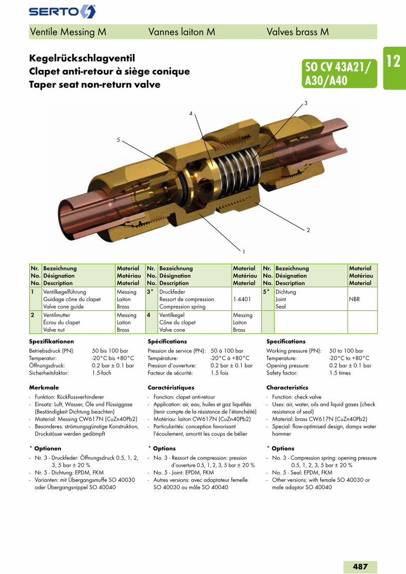
KegelrückschlagventilClapet anti-retour à siège coniqueTaper seat non-return valve
Nr.No.No.
BezeichnungDésignationDescription
MaterialMatériauMaterial
Nr.No.No.
BezeichnungDésignationDescription
MaterialMatériauMaterial
Nr.No.No.
BezeichnungDésignationDescription
MaterialMatériauMaterial
1 VentilkegelführungGuidage cône du clapetValve cone guide
MessingLaitonBrass
3* DruckfederRessort de compressionCompression spring
1.44015* Dichtung
JointSeal
NBR
2 VentilmutterÉcrou du clapetValve nut
MessingLaitonBrass
4 VentilkegelCône du clapetValve cone
MessingLaitonBrass
Spezifikationen
Betriebsdruck (PN): 50 bis 100 barTemperatur: -20°C bis +80°CÖffnungsdruck: 0.2 bar ± 0.1 barSicherheitsfaktor: 1.5-fach
Merkmale
- Funktion: Rückflussverhinderer- Einsatz: Luft, Wasser, Öle und Flüssiggase
(Beständigkeit Dichtung beachten)- Material: Messing CW617N (CuZn40Pb2)- Besonderes: strömungsgünstige Konstruktion,
Druckstösse werden gedämpft
* Optionen
- Nr. 3 - Druckfeder: Öffnungsdruck 0.5, 1, 2, 3, 5 bar ± 20 %
- Nr. 5 - Dichtung: EPDM, FKM- Varianten: mit Übergangsmuffe SO 40030
oder Übergangsnippel SO 40040
Spécifications
Pression de service (PN): 50 à 100 barTempérature: -20°C à +80°CPression d‘ouverture: 0.2 bar ± 0.1 barFacteur de sécurité: 1.5 fois
Caractéristiques
- Fonction: clapet anti-retour- Application: air, eau, huiles et gaz liquéfiés
(tenir compte de la résistance de l’étanchéité)- Matériau: laiton CW617N (CuZn40Pb2)- Particularités: conception favorisant
l’écoulement, amortit les coups de bélier
* Options
- No. 3 - Ressort de compression: pression d‘ouverture 0.5, 1, 2, 3, 5 bar ± 20 %
- No. 5 - Joint: EPDM, FKM- Autres versions: avec adaptateur femelle
SO 40030 ou mâle SO 40040
Specifications
Working pressure (PN): 50 to 100 barTemperature: -20°C to +80°COpening pressure: 0.2 bar ± 0.1 barSafety factor: 1.5 times
Characteristics
- Function: check valve- Uses: air, water, oils and liquid gases (check
resistance of seal) - Material: brass CW617N (CuZn40Pb2)- Special: flow-optimised design, damps water
hammer
* Options
- No. 3 - Compression spring: opening pressure 0.5, 1, 2, 3, 5 bar ± 20 %
- No. 5 - Seal: EPDM, FKM- Other versions: with female SO 40030 or
male adaptor SO 40040
Ventile Messing M Vannes laiton M Valves brass M
487
12
SO CV 43A21
Ventile Messing M Vannes laiton M Valves brass M
Exécutions en option
voir aperçu du chapitre
Optional services
see chapter overview
Sonderausführungen
siehe Kapitelübersicht
0
2
4
6
8
10
12
14
16
18
20
22
0 2 4 6 8 10 12 14 16 18 20 22 24
Durchfluss / Circulation / Flow rate [l/min]
Dru
ckab
fall
/ Per
te d
e pr
essi
on /
Pre
ssur
e dr
op [b
ar] SO CV 43A21-4
SO CV 43A21-5
SO CV 43A21-6
SO CV 43A21-8
SO CV 43A21-10
SO CV 43A21-12/14/15
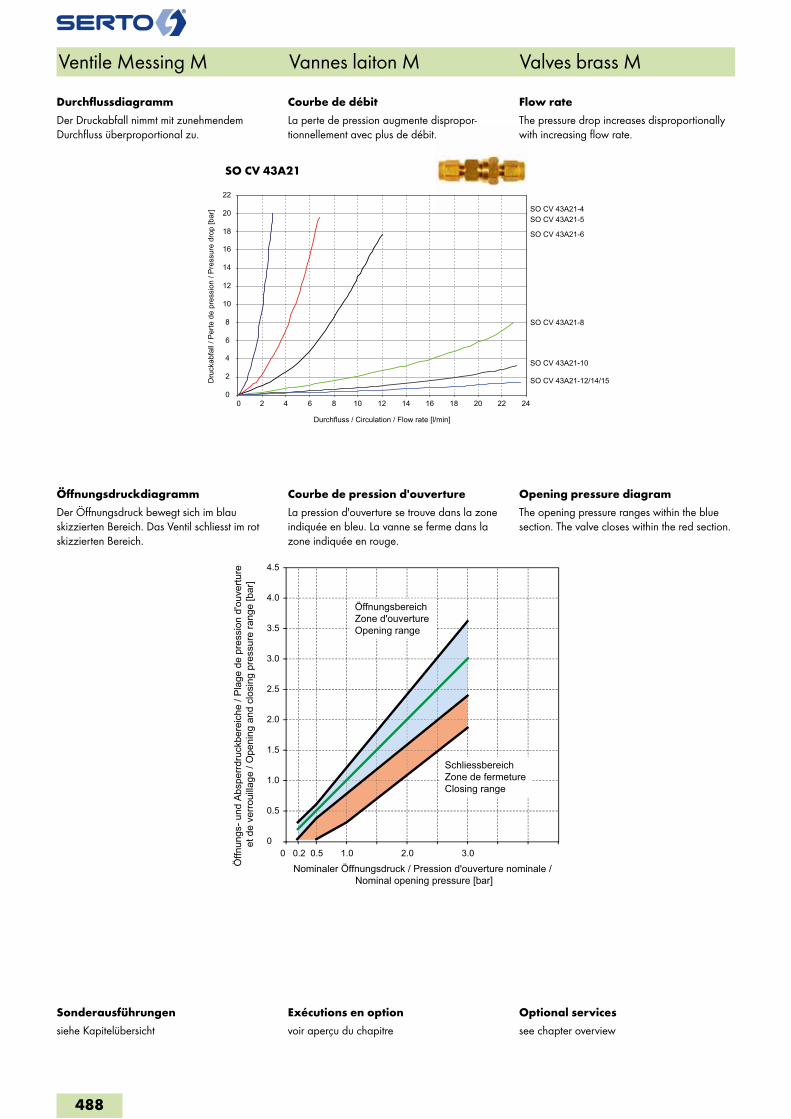
Courbe de débit
La perte de pression augmente dispropor-tionnellement avec plus de débit.
Courbe de pression d'ouverture
La pression d'ouverture se trouve dans la zone indiquée en bleu. La vanne se ferme dans la zone indiquée en rouge.
Flow rate
The pressure drop increases disproportionally with increasing flow rate.
Opening pressure diagram
The opening pressure ranges within the blue section. The valve closes within the red section.
Durchflussdiagramm
Der Druckabfall nimmt mit zunehmendem Durchfluss überproportional zu.
Öffnungsdruckdiagramm
Der Öffnungsdruck bewegt sich im blau skizzierten Bereich. Das Ventil schliesst im rot skizzierten Bereich.
0
0.5
1.0
1.5
2.0
2.5
3.0
3.5
4.0
4.5
0 0.50.2 1.0 2.0 3.0
Öffn
ungs
- und
Abs
perrd
ruck
bere
iche
/ Pl
age
de p
ress
ion
d'ou
vertu
re
et d
e ve
rroui
llage
/ O
peni
ng a
nd c
losi
ng p
ress
ure
rang
e [b
ar]
Nominaler Öffnungsdruck / Pression d'ouverture nominale / Nominal opening pressure [bar]
ÖffnungsbereichZone d'ouvertureOpening range
SchliessbereichZone de fermetureClosing range
488
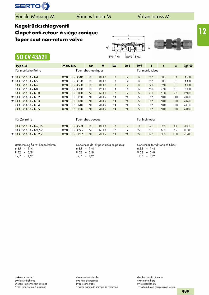
KegelrückschlagventilClapet anti-retour à siège coniqueTaper seat non-return valve
SO CV 43A21Type -d Mat.-Nr. bar M SW1 SW2 SW3 L z e kg/100Für metrische Rohre Pour tubes métriques For metric tubes
SO CV 43A21-4 028.3000.040 100 10x1.0 12 12 14 53.5 38.5 3.4 4.500 SO CV 43A21-5 028.3000.050 100 10x1.0 12 12 14 53.5 38.5 3.8 4.400 SO CV 43A21-6 028.3000.060 100 10x1.0 12 12 14 54.0 39.0 3.8 4.300 SO CV 43A21-8 028.3000.080 100 12x1.0 14 14 17 63.0 47.0 5.8 6.300 SO CV 43A21-10 028.3000.100 64 14x1.0 17 19 22 71.0 51.0 7.5 12.000
SO CV 43A21-12 028.3000.120 50 20x1.5 24 24 27 82.5 58.0 10.0 23.800 SO CV 43A21-13 028.3000.130 50 20x1.5 24 24 27 82.5 58.0 11.0 23.600 SO CV 43A21-14 028.3000.140 50 20x1.5 24 24 27 82.5 58.0 11.0 23.100 SO CV 43A21-15 028.3000.150 50 20x1.5 24 24 27 82.5 58.0 11.0 23.000
Für Zollrohre Pour tubes pouces For inch tubes
SO CV 43A21-6,35 028.3000.063 100 10x1.0 12 12 14 54.0 39.0 3.8 4.300 SO CV 43A21-9,52 028.3000.095 64 14x1.0 17 19 22 71.0 47.0 7.5 12.000
SO CV 43A21-12,7 028.3000.127 50 20x1.5 24 24 27 82.5 58.0 11.0 23.700
Umrechnung für "d" bei Zollrohren:6,35 = 1/49,52 = 3/812,7 = 1/2
Conversion de "d" pour tubes en pouces:6,35 = 1/49,52 = 3/812,7 = 1/2
Conversion for "d" for inch tubes:6,35 = 1/49,52 = 3/812,7 = 1/2
Ventile Messing M Vannes laiton M Valves brass M
d=Rohraussen-øe=kleinste BohrungL=Mass in montiertem Zustand*=mit reduziertem Klemmring
d=ø extérieur du tubee=ø-min. de passageL=après montage*=avec bague de serrage de réduction
d=tube outside diametere=minimum boreL=installed length*=with reduced compression ferrule
489
12
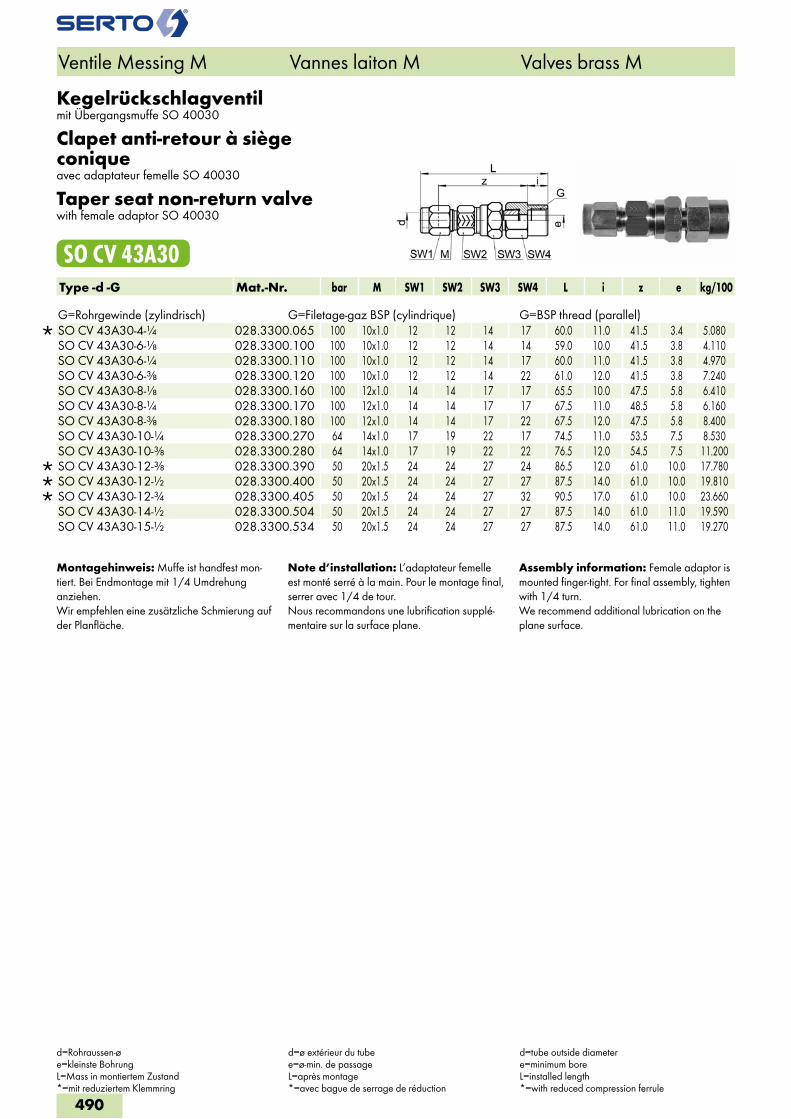
Kegelrückschlagventilmit Übergangsmuffe SO 40030
Clapet anti-retour à siège coniqueavec adaptateur femelle SO 40030
Taper seat non-return valvewith female adaptor SO 40030
SO CV 43A30Type -d -G Mat.-Nr. bar M SW1 SW2 SW3 SW4 L i z e kg/100 G=Rohrgewinde (zylindrisch) G=Filetage-gaz BSP (cylindrique) G=BSP thread (parallel)
SO CV 43A30-4-1/4 028.3300.065 100 10x1.0 12 12 14 17 60.0 11.0 41.5 3.4 5.080 SO CV 43A30-6-1/8 028.3300.100 100 10x1.0 12 12 14 14 59.0 10.0 41.5 3.8 4.110 SO CV 43A30-6-1/4 028.3300.110 100 10x1.0 12 12 14 17 60.0 11.0 41.5 3.8 4.970 SO CV 43A30-6-3/8 028.3300.120 100 10x1.0 12 12 14 22 61.0 12.0 41.5 3.8 7.240 SO CV 43A30-8-1/8 028.3300.160 100 12x1.0 14 14 17 17 65.5 10.0 47.5 5.8 6.410 SO CV 43A30-8-1/4 028.3300.170 100 12x1.0 14 14 17 17 67.5 11.0 48.5 5.8 6.160 SO CV 43A30-8-3/8 028.3300.180 100 12x1.0 14 14 17 22 67.5 12.0 47.5 5.8 8.400 SO CV 43A30-10-1/4 028.3300.270 64 14x1.0 17 19 22 17 74.5 11.0 53.5 7.5 8.530 SO CV 43A30-10-3/8 028.3300.280 64 14x1.0 17 19 22 22 76.5 12.0 54.5 7.5 11.200
SO CV 43A30-12-3/8 028.3300.390 50 20x1.5 24 24 27 24 86.5 12.0 61.0 10.0 17.780 SO CV 43A30-12-1/2 028.3300.400 50 20x1.5 24 24 27 27 87.5 14.0 61.0 10.0 19.810 SO CV 43A30-12-3/4 028.3300.405 50 20x1.5 24 24 27 32 90.5 17.0 61.0 10.0 23.660 SO CV 43A30-14-1/2 028.3300.504 50 20x1.5 24 24 27 27 87.5 14.0 61.0 11.0 19.590 SO CV 43A30-15-1/2 028.3300.534 50 20x1.5 24 24 27 27 87.5 14.0 61.0 11.0 19.270
Montagehinweis: Muffe ist handfest mon-tiert. Bei Endmontage mit 1/4 Umdrehung anziehen.Wir empfehlen eine zusätzliche Schmierung auf der Planfläche.
Note d’installation: L’adaptateur femelle est monté serré à la main. Pour le montage final, serrer avec 1/4 de tour.Nous recommandons une lubrification supplé-mentaire sur la surface plane.
Assembly information: Female adaptor is mounted finger-tight. For final assembly, tighten with 1/4 turn.We recommend additional lubrication on the plane surface.
Ventile Messing M Vannes laiton M Valves brass M
d=Rohraussen-øe=kleinste BohrungL=Mass in montiertem Zustand*=mit reduziertem Klemmring
d=ø extérieur du tubee=ø-min. de passageL=après montage*=avec bague de serrage de réduction
d=tube outside diametere=minimum boreL=installed length*=with reduced compression ferrule
490
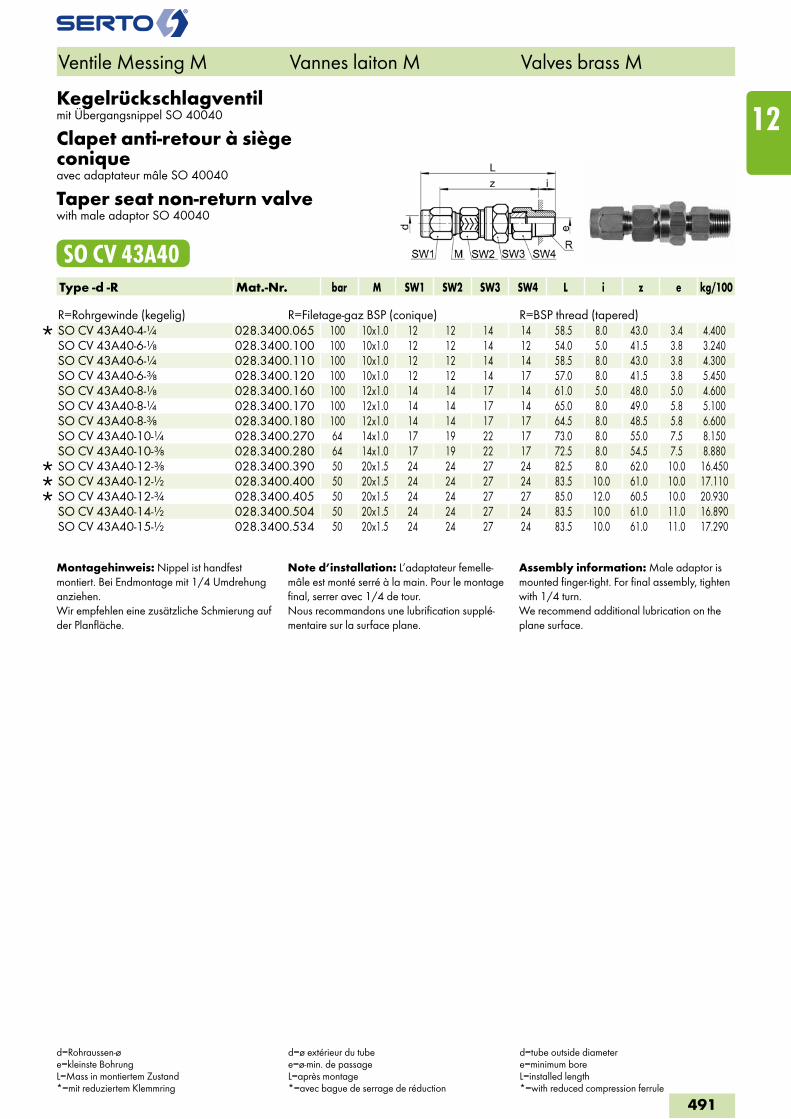
Kegelrückschlagventilmit Übergangsnippel SO 40040
Clapet anti-retour à siège coniqueavec adaptateur mâle SO 40040
Taper seat non-return valvewith male adaptor SO 40040
SO CV 43A40Type -d -R Mat.-Nr. bar M SW1 SW2 SW3 SW4 L i z e kg/100 R=Rohrgewinde (kegelig) R=Filetage-gaz BSP (conique) R=BSP thread (tapered)
SO CV 43A40-4-1/4 028.3400.065 100 10x1.0 12 12 14 14 58.5 8.0 43.0 3.4 4.400 SO CV 43A40-6-1/8 028.3400.100 100 10x1.0 12 12 14 12 54.0 5.0 41.5 3.8 3.240 SO CV 43A40-6-1/4 028.3400.110 100 10x1.0 12 12 14 14 58.5 8.0 43.0 3.8 4.300 SO CV 43A40-6-3/8 028.3400.120 100 10x1.0 12 12 14 17 57.0 8.0 41.5 3.8 5.450 SO CV 43A40-8-1/8 028.3400.160 100 12x1.0 14 14 17 14 61.0 5.0 48.0 5.0 4.600 SO CV 43A40-8-1/4 028.3400.170 100 12x1.0 14 14 17 14 65.0 8.0 49.0 5.8 5.100 SO CV 43A40-8-3/8 028.3400.180 100 12x1.0 14 14 17 17 64.5 8.0 48.5 5.8 6.600 SO CV 43A40-10-1/4 028.3400.270 64 14x1.0 17 19 22 17 73.0 8.0 55.0 7.5 8.150 SO CV 43A40-10-3/8 028.3400.280 64 14x1.0 17 19 22 17 72.5 8.0 54.5 7.5 8.880
SO CV 43A40-12-3/8 028.3400.390 50 20x1.5 24 24 27 24 82.5 8.0 62.0 10.0 16.450 SO CV 43A40-12-1/2 028.3400.400 50 20x1.5 24 24 27 24 83.5 10.0 61.0 10.0 17.110 SO CV 43A40-12-3/4 028.3400.405 50 20x1.5 24 24 27 27 85.0 12.0 60.5 10.0 20.930 SO CV 43A40-14-1/2 028.3400.504 50 20x1.5 24 24 27 24 83.5 10.0 61.0 11.0 16.890 SO CV 43A40-15-1/2 028.3400.534 50 20x1.5 24 24 27 24 83.5 10.0 61.0 11.0 17.290
Montagehinweis: Nippel ist handfest montiert. Bei Endmontage mit 1/4 Umdrehung anziehen.Wir empfehlen eine zusätzliche Schmierung auf der Planfläche.
Note d’installation: L’adaptateur femelle-mâle est monté serré à la main. Pour le montage final, serrer avec 1/4 de tour.Nous recommandons une lubrification supplé-mentaire sur la surface plane.
Assembly information: Male adaptor is mounted finger-tight. For final assembly, tighten with 1/4 turn.We recommend additional lubrication on the plane surface.
Ventile Messing M Vannes laiton M Valves brass M
d=Rohraussen-øe=kleinste BohrungL=Mass in montiertem Zustand*=mit reduziertem Klemmring
d=ø extérieur du tubee=ø-min. de passageL=après montage*=avec bague de serrage de réduction
d=tube outside diametere=minimum boreL=installed length*=with reduced compression ferrule
491
12
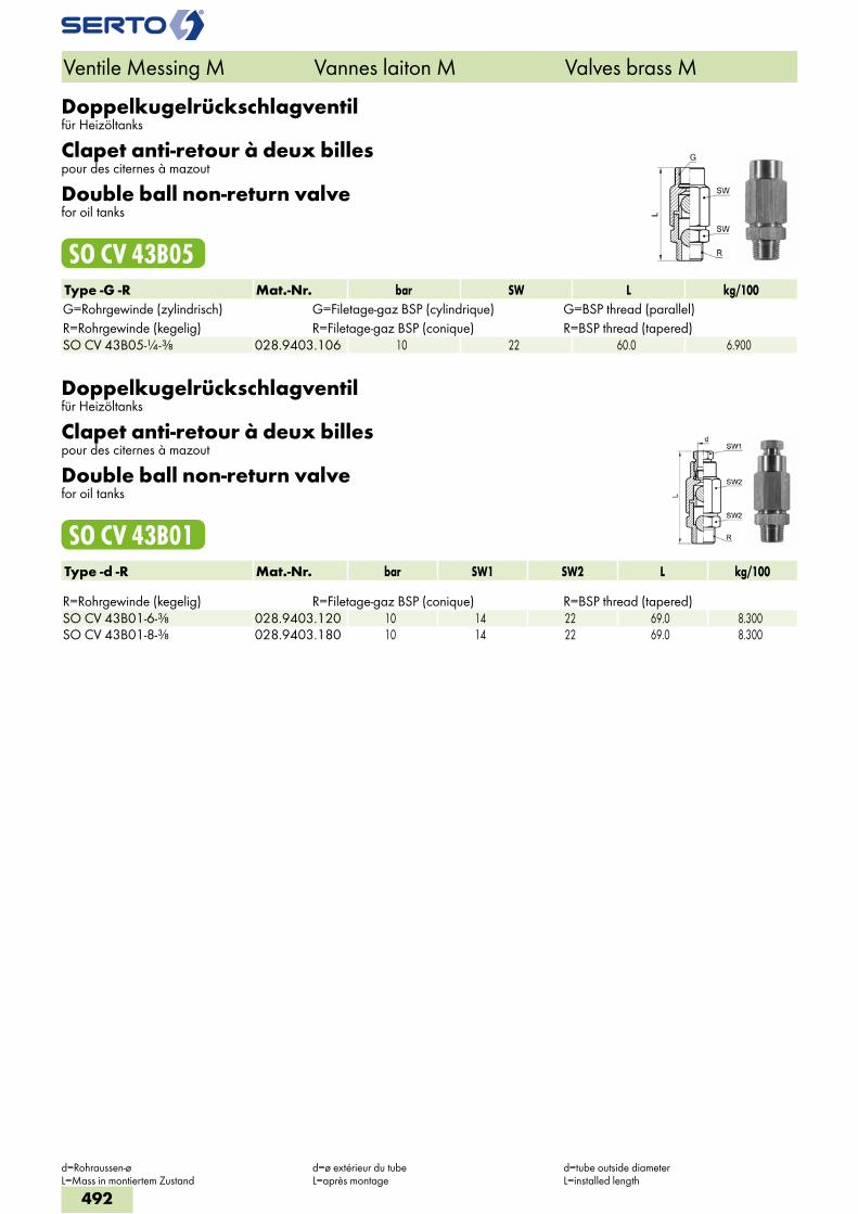
Doppelkugelrückschlagventilfür Heizöltanks
Clapet anti-retour à deux billespour des citernes à mazout
Double ball non-return valvefor oil tanks
SO CV 43B05Type -G -R Mat.-Nr. bar SW L kg/100G=Rohrgewinde (zylindrisch) G=Filetage-gaz BSP (cylindrique) G=BSP thread (parallel)R=Rohrgewinde (kegelig) R=Filetage-gaz BSP (conique) R=BSP thread (tapered)SO CV 43B05-1/4-3/8 028.9403.106 10 22 60.0 6.900
Doppelkugelrückschlagventilfür Heizöltanks
Clapet anti-retour à deux billespour des citernes à mazout
Double ball non-return valvefor oil tanks
SO CV 43B01Type -d -R Mat.-Nr. bar SW1 SW2 L kg/100 R=Rohrgewinde (kegelig) R=Filetage-gaz BSP (conique) R=BSP thread (tapered)SO CV 43B01-6-3/8 028.9403.120 10 14 22 69.0 8.300SO CV 43B01-8-3/8 028.9403.180 10 14 22 69.0 8.300
Ventile Messing M Vannes laiton M Valves brass M
d=Rohraussen-øL=Mass in montiertem Zustand
d=ø extérieur du tubeL=après montage
d=tube outside diameterL=installed length
492
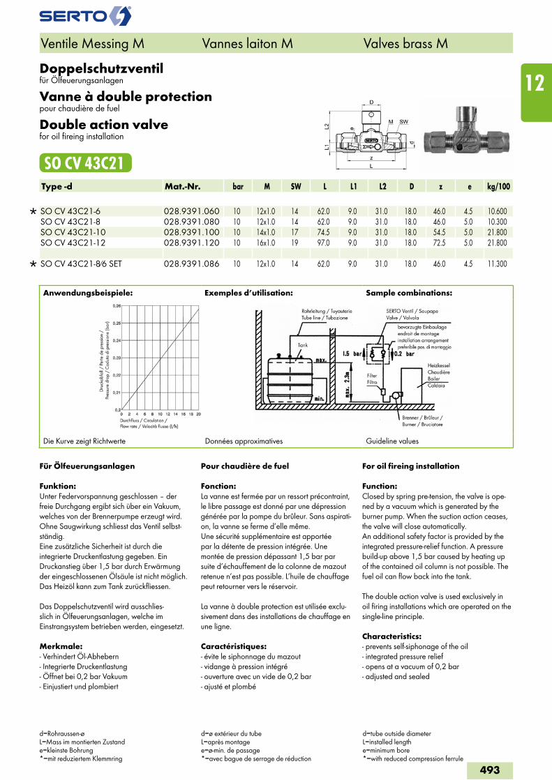
Doppelschutzventil für Ölfeuerungsanlagen
Vanne à double protectionpour chaudière de fuel
Double action valvefor oil fireing installation
SO CV 43C21Type -d Mat.-Nr. bar M SW L L1 L2 D z e kg/100
SO CV 43C21-6 028.9391.060 10 12x1.0 14 62.0 9.0 31.0 18.0 46.0 4.5 10.600 SO CV 43C21-8 028.9391.080 10 12x1.0 14 62.0 9.0 31.0 18.0 46.0 5.0 10.300 SO CV 43C21-10 028.9391.100 10 14x1.0 17 74.5 9.0 31.0 18.0 54.5 5.0 21.800 SO CV 43C21-12 028.9391.120 10 16x1.0 19 97.0 9.0 31.0 18.0 72.5 5.0 21.800
SO CV 43C21-8/6 SET 028.9391.086 10 12x1.0 14 62.0 9.0 31.0 18.0 46.0 4.5 11.300
Anwendungsbeispiele: Exemples d’utilisation: Sample combinations:
Die Kurve zeigt Richtwerte Données approximatives Guideline values
Ventile Messing M Vannes laiton M Valves brass M
d=Rohraussen-øL=Mass im montierten Zustande=kleinste Bohrung*=mit reduziertem Klemmring
d=ø extérieur du tubeL=après montagee=ø-min. de passage *=avec bague de serrage de réduction
d=tube outside diameterL=installed lengthe=minimum bore*=with reduced compression ferrule
Für Ölfeuerungsanlagen
Funktion:Unter Federvorspannung geschlossen – der freie Durchgang ergibt sich über ein Vakuum, welches von der Brennerpumpe erzeugt wird. Ohne Saugwirkung schliesst das Ventil selbst-ständig.Eine zusätzliche Sicherheit ist durch die integrierte Druckentlastung gegeben. Ein Druckanstieg über 1,5 bar durch Erwärmung der eingeschlossenen Ölsäule ist nicht möglich. Das Heizöl kann zum Tank zurückfliessen.
Das Doppelschutzventil wird ausschlies-slich in Ölfeuerungsanlagen, welche im Einstrangsystem betrieben werden, eingesetzt.
Merkmale:- Verhindert Öl-Abhebern- Integrierte Druckentlastung- Öffnet bei 0,2 bar Vakuum- Einjustiert und plombiert
Pour chaudière de fuel
Fonction:La vanne est fermée par un ressort précontraint, le libre passage est donné par une dépression générée par la pompe du brûleur. Sans aspirati-on, la vanne se ferme d’elle même.Une sécurité supplémentaire est apportée par la détente de pression intégrée. Une montée de pression dépassant 1,5 bar par suite d’échauffement de la colonne de mazout retenue n’est pas possible. L’huile de chauffage peut retourner vers le réservoir.
La vanne à double protection est utilisée exclu-sivement dans des installations de chauffage en une ligne.
Caractéristiques:- évite le siphonnage du mazout- vidange à pression intégré- ouverture avec un vide de 0,2 bar- ajusté et plombé
For oil fireing installation
Function:Closed by spring pre-tension, the valve is ope-ned by a vacuum which is generated by the burner pump. When the suction action ceases, the valve will close automatically.An additional safety factor is provided by the integrated pressure-relief function. A pressure build-up above 1,5 bar caused by heating up of the contained oil column is not possible. The fuel oil can flow back into the tank.
The double action valve is used exclusively in oil firing installations which are operated on the single-line principle.
Characteristics:- prevents self-siphonage of the oil- integrated pressure relief- opens at a vacuum of 0,2 bar- adjusted and sealed
493
12
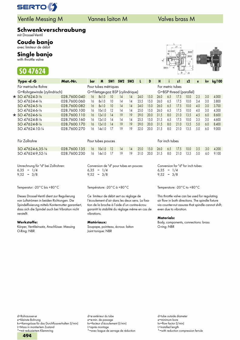
Schwenkverschraubungmit Drossel-Ventil
Coude banjoavec limiteur de débit
Single banjowith throttle valve
SO 47624Type -d -G Mat.-Nr. bar M SW1 SW2 SW3 L D H i z1 z2 e kv kg/100Für metrische Rohre Pour tubes métriques For metric tubesG=Rohrgewinde (zylindrisch) G=Filetage-gaz BSP (cylindrique) G=BSP thread (parallel)
SO 47624-3-1/8 028.7600.040 16 8x1.0 10 14 14 24.0 15.0 26.0 6.5 17.5 10.0 2.5 3.0 4.000 SO 47624-4-1/8 028.7600.060 16 8x1.0 10 14 14 23.5 15.0 26.0 6.5 17.5 10.0 3.4 3.0 3.800 SO 47624-5-1/8 028.7600.082 16 8x1.0 10 14 14 24.0 15.0 26.0 6.5 17.5 10.0 4.0 3.0 3.700 SO 47624-6-1/8 028.7600.100 16 10x1.0 12 14 14 25.0 15.0 26.0 6.5 17.5 10.0 4.0 3.0 4.300
SO 47624-6-1/4 028.7600.110 16 12x1.0 14 19 19 29.0 20.0 31.5 8.0 21.0 13.5 4.5 6.0 8.600 SO 47624-8-1/8 028.7600.160 16 12x1.0 14 14 14 25.5 15.0 31.5 6.5 17.5 10.0 3.5 3.0 4.600 SO 47624-8-1/4 028.7600.170 16 12x1.0 14 19 19 29.0 20.0 31.5 8.0 21.0 13.5 5.0 6.0 8.400 SO 47624-10-1/4 028.7600.270 16 14x1.0 17 19 19 32.0 20.0 31.5 8.0 21.0 13.5 5.0 6.0 9.000
Für Zollrohre Pour tubes pouces For inch tubes SO 47624-6,35-1/8 028.7600.135 16 10x1.0 12 14 14 25.0 15.0 26.0 6.5 17.5 10.0 3.5 3.0 4.200SO 47624-9,52-1/4 028.7600.230 16 14x1.0 17 19 19 31.0 20.0 31.5 8.0 21.0 13.5 5.0 6.0 9.100
Umrechnung für "d" bei Zollrohren:6,35 = 1/49,52 = 3/8
Conversion de "d" pour tubes en pouces:6,35 = 1/49,52 = 3/8
Conversion for "d" for inch tubes:6,35 = 1/49,52 = 3/8
Temperatur: -20°C bis +80°C
Dieses Drossel-Ventil dient zur Regulierung von Luftströmen in beiden Richtungen. Die Spindelfixierung mittels Kontermutter garantiert, dass sich die Spindel auch bei Vibration nicht verstellt.
Werkstoffe:Körper, Ventileinsatz, Anschlüsse: MessingO-Ring: NBR
Température: -20°C à +80°C
Ce limiteur de débit sert au réglage de l’écoulement d’air dans les deux sens. La fixa-tion de la broche à l’aide d’un contre-écrou garantit la stabilité du réglage même en cas de vibrations.
Matériaux:Soupape, pointeau, écrous: laitonJoint torique: NBR
Temperature: -20°C to +80°C
This throttle valve can be used for regulating air flow in both directions. The spindle fixture via counter-nut assures that spindle cannot shift, even due to vibration.
Materials:Body, components, connections: brassO-ring: NBR
Ventile Messing M Vannes laiton M Valves brass M
d=Rohraussen-øe=kleinste Bohrungkv=Kenngrösse für das Durchflussverhalten (l/min)L=Mass in montiertem Zustand*=mit reduziertem Klemmring
d=ø extérieur du tubee=ø-min. de passagekv=facteur d’écoulement (l/min)L=après montage*=avec bague de serrage de réduction
d=tube outside diametere=minimum borekv=flow factor (l/min)L=installed length*=with reduction compression ferrule
494
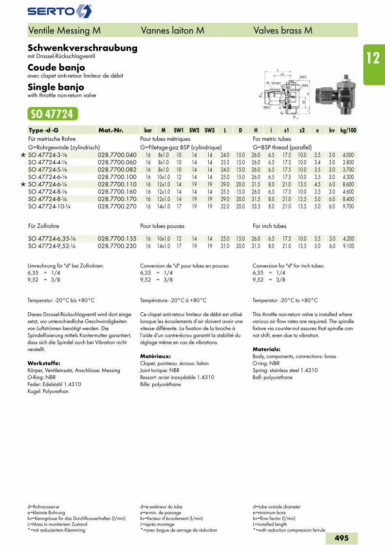
Schwenkverschraubungmit Drossel-Rückschlagventil
Coude banjoavec clapet anti-retour limiteur de débit
Single banjowith throttle non-return valve
SO 47724Type -d -G Mat.-Nr. bar M SW1 SW2 SW3 L D H i z1 z2 e kv kg/100Für metrische Rohre Pour tubes métriques For metric tubesG=Rohrgewinde (zylindrisch) G=Filetage-gaz BSP (cylindrique) G=BSP thread (parallel)
SO 47724-3-1/8 028.7700.040 16 8x1.0 10 14 14 24.0 15.0 26.0 6.5 17.5 10.0 2.5 3.0 4.000 SO 47724-4-1/8 028.7700.060 16 8x1.0 10 14 14 23.5 15.0 26.0 6.5 17.5 10.0 3.4 3.0 3.800 SO 47724-5-1/8 028.7700.082 16 8x1.0 10 14 14 24.0 15.0 26.0 6.5 17.5 10.0 3.5 3.0 3.700 SO 47724-6-1/8 028.7700.100 16 10x1.0 12 14 14 25.0 15.0 26.0 6.5 17.5 10.0 3.5 3.0 4.300
SO 47724-6-1/4 028.7700.110 16 12x1.0 14 19 19 29.0 20.0 31.5 8.0 21.0 13.5 4.5 6.0 8.600 SO 47724-8-1/8 028.7700.160 16 12x1.0 14 14 14 25.5 15.0 26.0 6.5 17.5 10.0 3.5 3.0 4.600 SO 47724-8-1/4 028.7700.170 16 12x1.0 14 19 19 29.0 20.0 31.5 8.0 21.0 13.5 5.0 6.0 8.400 SO 47724-10-1/4 028.7700.270 16 14x1.0 17 19 19 32.0 20.0 33.5 8.0 21.0 13.5 5.0 6.0 9.700
Für Zollrohre Pour tubes pouces For inch tubes
SO 47724-6,35-1/8 028.7700.135 16 10x1.0 12 14 14 25.0 15.0 26.0 6.5 17.5 10.0 3.5 3.0 4.200 SO 47724-9,52-1/4 028.7700.230 16 14x1.0 17 19 19 31.0 20.0 31.5 8.0 21.0 13.5 5.0 6.0 9.100
Umrechnung für "d" bei Zollrohren:6,35 = 1/49,52 = 3/8
Conversion de "d" pour tubes en pouces:6,35 = 1/49,52 = 3/8
Conversion for "d" for inch tubes:6,35 = 1/49,52 = 3/8
Temperatur: -20°C bis +80°C
Dieses Drossel-Rückschlagventil wird dort einge-setzt, wo unterschiedliche Geschwindigkeiten von Luftströmen benötigt werden. Die Spindelfixierung mittels Kontermutter garantiert, dass sich die Spindel auch bei Vibration nicht verstellt.
Werkstoffe:Körper, Ventileinsatz, Anschlüsse: MessingO-Ring: NBRFeder: Edelstahl 1.4310Kugel: Polyurethan
Température: -20°C à +80°C
Ce clapet anti-retour limiteur de débit est utilisé lorsque les écoulements d’air doivent avoir une vitesse différente. La fixation de la broche à l’aide d’un contre-écrou garantit la stabilité du réglage même en cas de vibrations.
Matériaux:Clapet, pointeau. écrous: laitonJoint torique: NBRRessort: acier inoxydable 1.4310Bille: polyuréthane
Temperatur: -20°C to +80°C
This throttle non-return valve is installed where various air flow rates are required. The spindle fixture via counter-nut assures that spindle can-not shift, even due to vibration.
Materials:Body, components, connections: brassO-ring: NBRSpring: stainless steel 1.4310Ball: polyurethane
Ventile Messing M Vannes laiton M Valves brass M
d=Rohraussen-øe=kleinste Bohrungkv=Kenngrösse für das Durchflussverhalten (l/min)L=Mass in montiertem Zustand*=mit reduziertem Klemmring
d=ø extérieur du tubee=ø-min. de passagekv=facteur d’écoulement (l/min)L=après montage*=avec bague de serrage de réduction
d=tube outside diametere=minimum borekv=flow factor (l/min)L=installed length*=with reduction compression ferrule
495
12
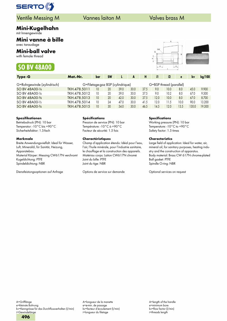
Mini-Kugelhahnmit Innengewinde
Mini vanne à billeavec taraudage
Mini-ball valvewith female thread
SO BV 48A00Type -G Mat.-Nr. bar SW L A H i1 i2 e kv kg/100 G=Rohrgewinde (zylindrisch) G=Filetage-gaz BSP (cylindrique) G=BSP thread (parallel)SO BV 48A00-1/8 TKH.478.5011 10 20 39.0 30.0 37.5 9.0 10.0 8.0 45.0 9.900SO BV 48A00-1/4 TKH.478.5012 10 20 39.0 30.0 37.5 9.0 10.2 8.0 67.0 9.500SO BV 48A00-3/8 TKH.478.5013 10 20 42.0 30.0 37.5 12.0 10.0 8.0 67.0 8.700SO BV 48A00-1/2 TKH.478.5014 10 24 47.0 30.0 41.5 12.0 11.5 10.0 90.0 13.200SO BV 48A00-3/4 TKH.478.5015 10 30 54.0 30.0 46.5 14.5 12.0 13.5 130.0 19.300
SpezifikationenBetriebsdruck (PN): 10 barTemperatur: -10°C bis +90°CSicherheitsfaktor: 1.5-fach
MerkmaleBreite Anwendungsvielfalt: Ideal für Wasser, Luft, Mineralöl, für Sanitär, Heizung, Apparatebau.Material Körper: Messing CW617N verchromtKugeldichtung: PTFESpindeldichtung: NBR
Dienstleistungsoptionen auf Anfrage
SpécificationsPression de service (PN): 10 barTempérature: -10°C à +90°CFacteur de sécurité: 1.5 fois
CharactéristiquesChamp d’application étendu: Idéal pour l’eau, l’air, l’huile minérale, pour l’industrie sanitaire, le chauffage et la construction des appareils.Matériau corps: Laiton CW617N chroméJoint du bille: PTFEJoint du tige: NBR
Options de service sur demande
SpecificationsWorking pressure (PN): 10 barTemperature: -10°C to +90°CSafety factor: 1.5 times
CharacteristicsLarge field of application: Ideal for water, air, mineral oil, for sanitary purposes, heating indu-stry and the construction of apparatus.Body material: Brass CW 617N chrome-platedBall gasket: PTFESpindle O-ring: NBR
Optional services on request
Ventile Messing M Vannes laiton M Valves brass M
A=Grifflängee=kleinste Bohrungkv=Kenngrösse für das Durchflussverhalten (l/min)i=Gewindelänge
A=longueur de la manettee=ø-min. de passagekv=facteur d’écoulement (l/min)i=longueur du filetage
A=length of the handlee=minimum borekv=flow factor (l/min)i=threads length
496
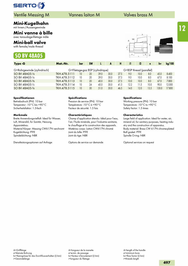
Mini-Kugelhahnmit Innen-/Aussengewinde
Mini vanne à billeavec taraudage-filetage mâle
Mini-ball valvewith female/male thread
SO BV 48A05Type -G Mat.-Nr. bar SW L A H i1 i2 e kv kg/100 G=Rohrgewinde (zylindrisch) G=Filetage-gaz BSP (cylindrique) G=BSP thread (parallel)SO BV 48A05-1/8 TKH.478.5111 10 20 39.0 30.0 37.5 9.0 10.0 8.0 45.0 8.400SO BV 48A05-1/4 TKH.478.5112 10 20 39.0 30.0 37.5 9.0 10.0 8.0 67.0 8.100SO BV 48A05-3/8 TKH.478.5113 10 20 40.0 30.0 37.5 10.0 10.0 8.0 67.0 7.800SO BV 48A05-1/2 TKH.478.5114 10 24 45.0 30.0 41.5 12.2 11.5 10.0 90.0 12.000SO BV 48A05-3/4 TKH.478.5115 10 30 51.0 30.0 46.5 14.0 12.0 13.5 130.0 17.800
SpezifikationenBetriebsdruck (PN): 10 barTemperatur: -10°C bis +90°CSicherheitsfaktor: 1.5-fach
MerkmaleBreite Anwendungsvielfalt: Ideal für Wasser, Luft, Mineralöl, für Sanitär, Heizung, Apparatebau.Material Körper: Messing CW617N verchromtKugeldichtung: PTFESpindeldichtung: NBR
Dienstleistungsoptionen auf Anfrage
SpécificationsPression de service (PN): 10 barTempérature: -10°C à +90°CFacteur de sécurité: 1.5 fois
CharactéristiquesChamp d’application étendu: Idéal pour l’eau, l’air, l’huile minérale, pour l’industrie sanitaire, le chauffage et la construction des appareils.Matériau corps: Laiton CW617N chroméJoint du bille: PTFEJoint du tige: NBR
Options de service sur demande
SpecificationsWorking pressure (PN): 10 barTemperature: -10°C to +90°CSafety factor: 1.5 times
CharacteristicsLarge field of application: Ideal for water, air, mineral oil, for sanitary purposes, heating indu-stry and the construction of apparatus.Body material: Brass CW 617N chrome-platedBall gasket: PTFESpindle O-ring: NBR
Optional services on request
A=Grifflängee=kleinste Bohrungkv=Kenngrösse für das Durchflussverhalten (l/min)i=Gewindelänge
A=longueur de la manettee=ø-min. de passagekv=facteur d’écoulement (l/min)i=longueur du filetage
A=length of the handlee=minimum borekv=flow factor (l/min)i=threads length
497
12
Ventile Messing M Vannes laiton M Valves brass M
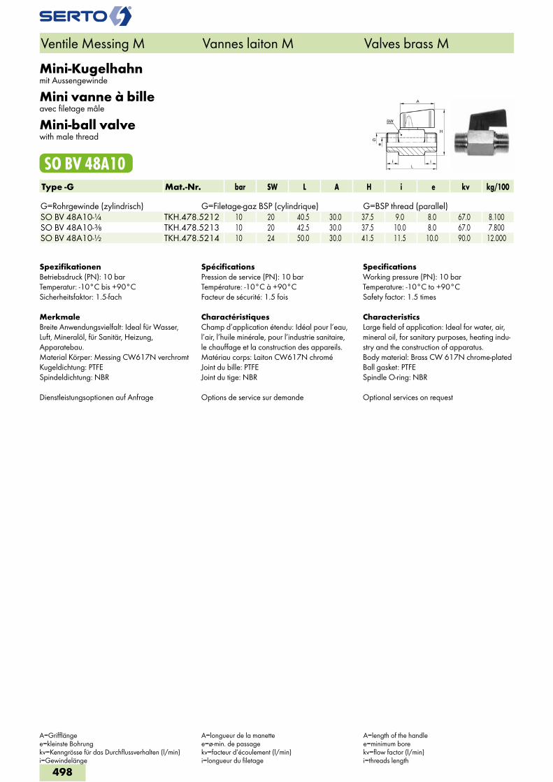
Mini-Kugelhahnmit Aussengewinde
Mini vanne à billeavec filetage mâle
Mini-ball valvewith male thread
SO BV 48A10Type -G Mat.-Nr. bar SW L A H i e kv kg/100 G=Rohrgewinde (zylindrisch) G=Filetage-gaz BSP (cylindrique) G=BSP thread (parallel)SO BV 48A10-1/4 TKH.478.5212 10 20 40.5 30.0 37.5 9.0 8.0 67.0 8.100SO BV 48A10-3/8 TKH.478.5213 10 20 42.5 30.0 37.5 10.0 8.0 67.0 7.800SO BV 48A10-1/2 TKH.478.5214 10 24 50.0 30.0 41.5 11.5 10.0 90.0 12.000
SpezifikationenBetriebsdruck (PN): 10 barTemperatur: -10°C bis +90°CSicherheitsfaktor: 1.5-fach
MerkmaleBreite Anwendungsvielfalt: Ideal für Wasser, Luft, Mineralöl, für Sanitär, Heizung, Apparatebau.Material Körper: Messing CW617N verchromtKugeldichtung: PTFESpindeldichtung: NBR
Dienstleistungsoptionen auf Anfrage
SpécificationsPression de service (PN): 10 barTempérature: -10°C à +90°CFacteur de sécurité: 1.5 fois
CharactéristiquesChamp d’application étendu: Idéal pour l’eau, l’air, l’huile minérale, pour l’industrie sanitaire, le chauffage et la construction des appareils.Matériau corps: Laiton CW617N chroméJoint du bille: PTFEJoint du tige: NBR
Options de service sur demande
SpecificationsWorking pressure (PN): 10 barTemperature: -10°C to +90°CSafety factor: 1.5 times
CharacteristicsLarge field of application: Ideal for water, air, mineral oil, for sanitary purposes, heating indu-stry and the construction of apparatus.Body material: Brass CW 617N chrome-platedBall gasket: PTFESpindle O-ring: NBR
Optional services on request
A=Grifflängee=kleinste Bohrungkv=Kenngrösse für das Durchflussverhalten (l/min)i=Gewindelänge
A=longueur de la manettee=ø-min. de passagekv=facteur d’écoulement (l/min)i=longueur du filetage
A=length of the handlee=minimum borekv=flow factor (l/min)i=threads length
498
Ventile Messing M Vannes laiton M Valves brass M
SO NV 01A21SO NV 01C21
2
5
1
3
4
6
9
7
8
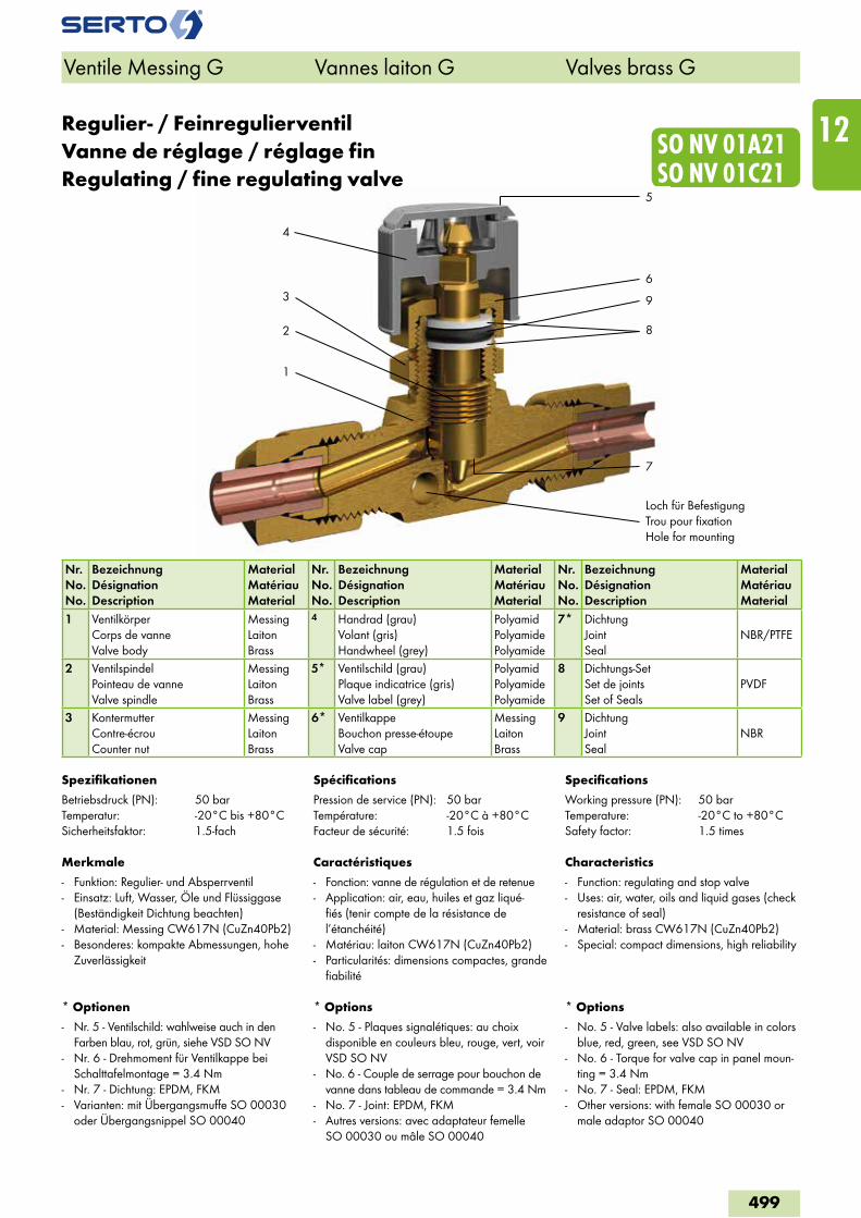
Regulier- / FeinregulierventilVanne de réglage / réglage finRegulating / fine regulating valve
Nr.No.No.
BezeichnungDésignationDescription
MaterialMatériauMaterial
Nr.No.No.
BezeichnungDésignationDescription
MaterialMatériauMaterial
Nr.No.No.
BezeichnungDésignationDescription
MaterialMatériauMaterial
1 VentilkörperCorps de vanneValve body
MessingLaitonBrass
4 Handrad (grau)Volant (gris)Handwheel (grey)
PolyamidPolyamidePolyamide
7* DichtungJointSeal
NBR/PTFE
2 VentilspindelPointeau de vanneValve spindle
MessingLaitonBrass
5* Ventilschild (grau)Plaque indicatrice (gris)Valve label (grey)
PolyamidPolyamidePolyamide
8 Dichtungs-SetSet de jointsSet of Seals
PVDF
3 KontermutterContre-écrouCounter nut
MessingLaitonBrass
6* VentilkappeBouchon presse-étoupeValve cap
MessingLaitonBrass
9 DichtungJointSeal
NBR
Spezifikationen
Betriebsdruck (PN): 50 barTemperatur: -20°C bis +80°CSicherheitsfaktor: 1.5-fach
Merkmale
- Funktion: Regulier- und Absperrventil- Einsatz: Luft, Wasser, Öle und Flüssiggase
(Beständigkeit Dichtung beachten)- Material: Messing CW617N (CuZn40Pb2)- Besonderes: kompakte Abmessungen, hohe
Zuverlässigkeit
* Optionen
- Nr. 5 - Ventilschild: wahlweise auch in den Farben blau, rot, grün, siehe VSD SO NV
- Nr. 6 - Drehmoment für Ventilkappe bei Schalttafelmontage = 3.4 Nm
- Nr. 7 - Dichtung: EPDM, FKM- Varianten: mit Übergangsmuffe SO 00030
oder Übergangsnippel SO 00040
Spécifications
Pression de service (PN): 50 barTempérature: -20°C à +80°CFacteur de sécurité: 1.5 fois
Caractéristiques
- Fonction: vanne de régulation et de retenue- Application: air, eau, huiles et gaz liqué-
fiés (tenir compte de la résistance de l’étanchéité)
- Matériau: laiton CW617N (CuZn40Pb2)- Particularités: dimensions compactes, grande
fiabilité
* Options
- No. 5 - Plaques signalétiques: au choix disponible en couleurs bleu, rouge, vert, voir VSD SO NV
- No. 6 - Couple de serrage pour bouchon de vanne dans tableau de commande = 3.4 Nm
- No. 7 - Joint: EPDM, FKM- Autres versions: avec adaptateur femelle
SO 00030 ou mâle SO 00040
Specifications
Working pressure (PN): 50 barTemperature: -20°C to +80°CSafety factor: 1.5 times
Characteristics
- Function: regulating and stop valve- Uses: air, water, oils and liquid gases (check
resistance of seal) - Material: brass CW617N (CuZn40Pb2)- Special: compact dimensions, high reliability
* Options
- No. 5 - Valve labels: also available in colors blue, red, green, see VSD SO NV
- No. 6 - Torque for valve cap in panel moun-ting = 3.4 Nm
- No. 7 - Seal: EPDM, FKM- Other versions: with female SO 00030 or
male adaptor SO 00040
Ventile Messing G Vannes laiton G Valves brass G
499
12
Loch für BefestigungTrou pour fixationHole for mounting
SO NV 01A21 SO NV 01C21
Ventile Messing G Vannes laiton G Valves brass G
Exécutions en option
voir aperçu du chapitre
Accessoires
Support de fixation voir SO 09900
Optional services
see chapter overview
Accessoires
Flange mount for wall fastening see SO 09900
Sonderausführungen
siehe Kapitelübersicht
Zubehör
Anschraubfuss für Wandmontage siehe SO 09900
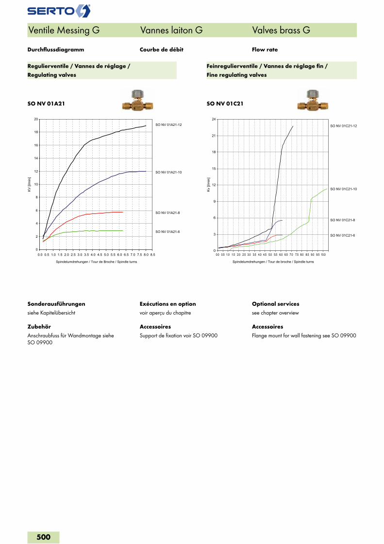
Courbe de débit Flow rateDurchflussdiagramm
0
2
4
6
8
10
12
14
16
18
20
0.0 0.5 1.0 1.5 2.0 2.5 3.0 3.5 4.0 4.5 5.0 5.5 6.0 6.5 7.0 7.5 8.0 8.5
KV [l
/min
]
Spindelumdrehungen / Tour de Broche / Spindle turns
SO NV 01A21-6
SO NV 01A21-8
SO NV 01A21-10
SO NV 01A21-12
0
3
6
9
12
15
18
21
24
Kv [l
/min
]
Spindelumdrehungen / Tour de broche / Spindle turns
0.0 0.5 1.0 1.5 2.0 2.5 3.0 3.5 4.0 4.5 5.0 5.5 6.0 6.5 7.0 7.5 8.0 8.5 9.0 9.5 10.0
SO NV 01C21-12
SO NV 01C21-10
SO NV 01C21-8
SO NV 01C21-6
Regulierventile / Vannes de réglage /
Regulating valves
Feinregulierventile / Vannes de réglage fin /
Fine regulating valves
500
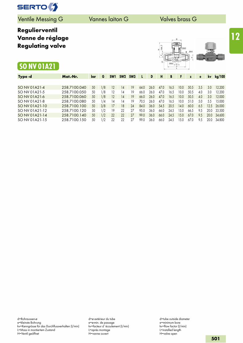
RegulierventilVanne de réglageRegulating valve
SO NV 01A21Type -d Mat.-Nr. bar G SW1 SW2 SW3 L D H B F z e kv kg/100 SO NV 01A21-4 258.7100.040 50 1/8 12 14 19 64.0 26.0 47.0 16.5 10.0 50.5 3.5 3.0 12.200SO NV 01A21-5 258.7100.050 50 1/8 12 14 19 66.0 26.0 47.0 16.5 10.0 50.5 4.0 3.0 12.200SO NV 01A21-6 258.7100.060 50 1/8 12 14 19 66.0 26.0 47.0 16.5 10.0 50.5 4.0 3.0 12.000SO NV 01A21-8 258.7100.080 50 1/4 14 14 19 70.5 26.0 47.0 16.5 10.0 51.0 5.0 5.5 15.000SO NV 01A21-10 258.7100.100 50 3/8 17 18 24 84.0 36.0 54.5 20.5 14.0 60.0 6.5 12.5 26.000SO NV 01A21-12 258.7100.120 50 1/2 19 22 27 95.0 36.0 66.0 24.5 15.0 66.5 9.5 20.0 33.500SO NV 01A21-14 258.7100.140 50 1/2 22 22 27 99.0 36.0 66.0 24.5 15.0 67.0 9.5 20.0 34.600SO NV 01A21-15 258.7100.150 50 1/2 22 22 27 99.0 36.0 66.0 24.5 15.0 67.0 9.5 20.0 34.800
Ventile Messing G Vannes laiton G Valves brass G
d=Rohraussen-øe=kleinste Bohrungkv=Kenngrösse für das Durchflussverhalten (l/min)L=Mass in montiertem ZustandH=Ventil geöffnet
d=ø extérieur du tubee=ø-min. de passagekv=facteur d´écoulement (l/min)L=après montageH=vanne ouvert
d=tube outside diametere=minimum borekv=flow factor (l/min)L=installed lengthH=valve open
501
12
Regulierventilmit Übergangsmuffe SO 00030
Vanne de réglageavec adaptateur femelle SO 00030
Regulating valvewith female adaptor SO 00030
SO NV 01A30Type -d -G Mat.-Nr. bar G2 SW1 SW2 SW3 L H B F i z1 z2 e kv kg/100 G=Rohrgewinde (zylindrisch) G=Filetage-gaz BSP (cylindrique) G=BSP thread (parallel)SO NV 01A30-4-1/8 258.7130.060 50 1/8 12 14 19 32.0 47.0 16.5 10.0 8.0 25.0 30.5 4.0 4.5 13.194SO NV 01A30-5-1/8 258.7130.082 50 1/8 12 14 19 32.0 47.0 16.5 10.0 8.0 25.0 30.5 4.0 5.0 13.141SO NV 01A30-6-1/8 258.7130.100 50 1/8 12 14 19 32.0 47.0 16.5 10.0 8.0 25.0 30.5 4.0 5.5 12.878SO NV 01A30-6-1/4 258.7130.110 50 1/8 12 14 19 32.0 47.0 16.5 10.0 9.0 25.0 31.0 4.0 5.5 15.128SO NV 01A30-8-1/8 258.7130.160 50 1/4 14 14 19 35.0 47.0 16.5 10.0 8.0 25.0 31.0 5.0 6.5 15.450SO NV 01A30-8-1/4 258.7130.170 50 1/4 14 14 19 35.0 47.0 16.5 10.0 9.0 25.5 31.5 5.0 6.5 16.750SO NV 01A30-8-3/8 258.7130.180 50 1/4 14 14 19 35.0 47.0 16.5 10.0 9.5 25.0 32.5 5.0 6.5 18.350SO NV 01A30-8-1/2 258.7130.185 50 1/4 14 14 19 35.0 47.0 16.5 10.0 11.5 25.5 33.0 5.0 6.5 22.450SO NV 01A30-10-1/4 258.7130.270 50 3/8 17 18 24 42.0 54.5 20.5 14.0 9.0 30.0 36.0 6.5 15.0 27.750SO NV 01A30-10-3/8 258.7130.280 50 3/8 17 18 24 42.0 54.5 20.5 14.0 9.5 30.0 37.0 6.5 15.0 27.650SO NV 01A30-10-1/2 258.7130.285 50 3/8 17 18 24 42.0 54.5 20.5 14.0 11.5 30.0 37.5 6.5 15.0 35.000SO NV 01A30-12-1/4 258.7130.380 50 1/2 19 22 27 47.5 66.0 24.5 15.0 9.0 33.0 39.0 9.5 38.0 35.200SO NV 01A30-12-3/8 258.7130.390 50 1/2 19 22 27 47.5 66.0 24.5 15.0 9.5 33.0 40.0 9.5 38.0 36.350SO NV 01A30-12-1/2 258.7130.400 50 1/2 19 22 27 47.5 66.0 24.5 15.0 11.5 33.0 40.0 9.5 38.0 40.100SO NV 01A30-12-3/4 258.7130.405 50 1/2 19 22 27 47.5 66.0 24.5 15.0 14.0 33.0 41.5 9.5 38.0 41.250SO NV 01A30-14-1/2 258.7130.504 50 1/2 22 22 27 49.5 66.0 24.5 15.0 11.0 33.5 40.0 9.5 40.0 40.400SO NV 01A30-15-1/2 258.7130.534 50 1/2 22 22 27 49.5 66.0 24.5 15.0 11.0 33.5 40.0 9.5 40.0 40.400
D = ø 26 mm ≤ Anschlussgrösse 8 ø 36 mm ≥ Anschlussgrösse 10
D = ø 26 mm ≤ Dimension 8 ø 36 mm ≥ Dimension 10
D = ø 26 mm ≤ Dimension 8 ø 36 mm ≥ Dimension 10
Montagehinweis: Muffe ist handfest mon-tiert. Bei Endmontage mit 1/4 Umdrehung anziehen.Wir empfehlen eine zusätzliche Schmierung auf der Planfläche.
Note d’installation: L’adaptateur femelle est monté serré à la main. Pour le montage final, serrer avec 1/4 de tour.Nous recommandons une lubrification supplé-mentaire sur la surface plane.
Assembly information: Female adaptor is mounted finger-tight. For final assembly, tighten with 1/4 turn.We recommend additional lubrication on the plane surface.
Ventile Messing G Vannes laiton G Valves brass G
d=Rohraussen-øe=kleinste Bohrungkv=Kenngrösse für das Durchflussverhalten (l/min)L=Mass in montiertem ZustandH=Ventil geöffnet
d=ø extérieur du tubee=ø-min. de passagekv=facteur d´écoulement (l/min)L=après montageH=vanne ouvert
d=tube outside diametere=minimum borekv=flow factor (l/min)L=installed lengthH=valve open
502
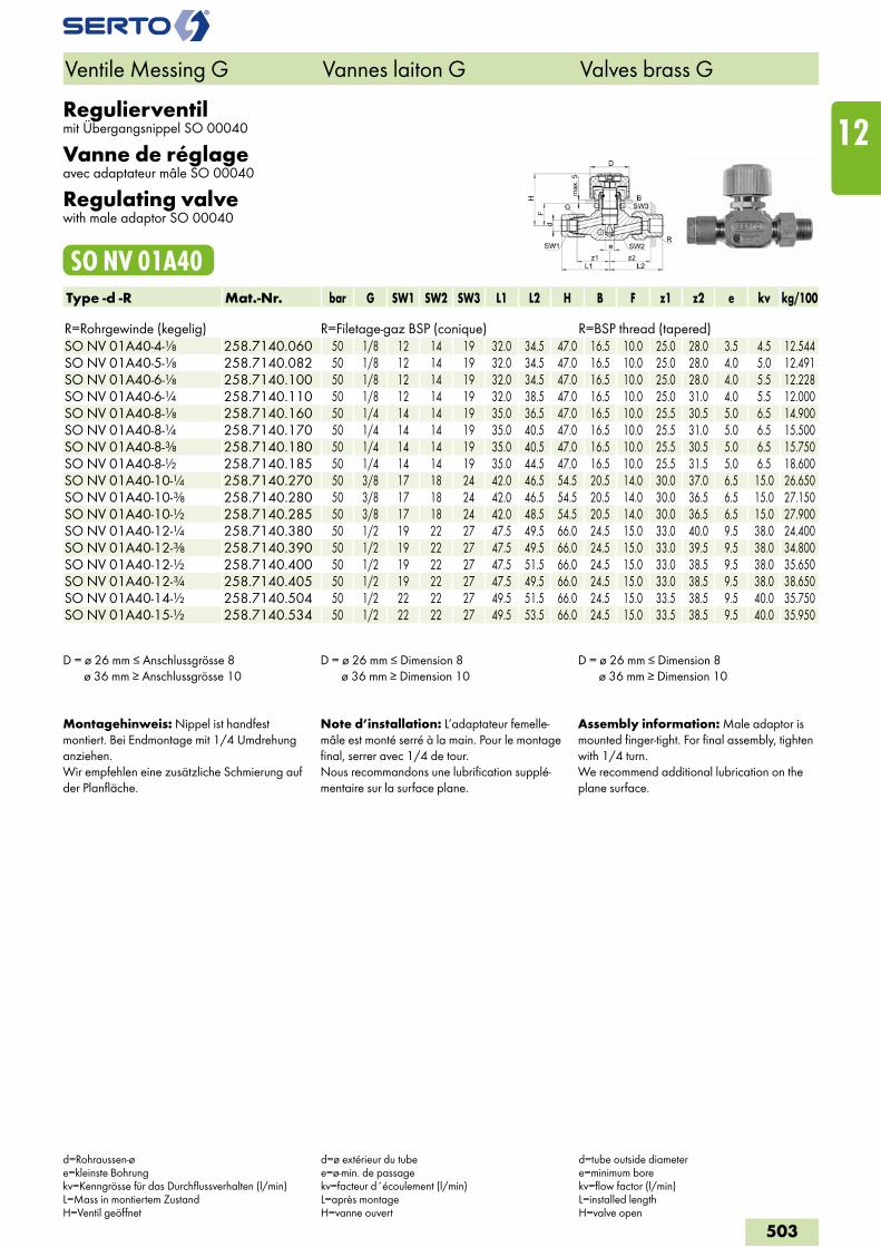
Regulierventilmit Übergangsnippel SO 00040
Vanne de réglageavec adaptateur mâle SO 00040
Regulating valvewith male adaptor SO 00040
SO NV 01A40Type -d -R Mat.-Nr. bar G SW1 SW2 SW3 L1 L2 H B F z1 z2 e kv kg/100 R=Rohrgewinde (kegelig) R=Filetage-gaz BSP (conique) R=BSP thread (tapered)SO NV 01A40-4-1/8 258.7140.060 50 1/8 12 14 19 32.0 34.5 47.0 16.5 10.0 25.0 28.0 3.5 4.5 12.544SO NV 01A40-5-1/8 258.7140.082 50 1/8 12 14 19 32.0 34.5 47.0 16.5 10.0 25.0 28.0 4.0 5.0 12.491SO NV 01A40-6-1/8 258.7140.100 50 1/8 12 14 19 32.0 34.5 47.0 16.5 10.0 25.0 28.0 4.0 5.5 12.228SO NV 01A40-6-1/4 258.7140.110 50 1/8 12 14 19 32.0 38.5 47.0 16.5 10.0 25.0 31.0 4.0 5.5 12.000SO NV 01A40-8-1/8 258.7140.160 50 1/4 14 14 19 35.0 36.5 47.0 16.5 10.0 25.5 30.5 5.0 6.5 14.900SO NV 01A40-8-1/4 258.7140.170 50 1/4 14 14 19 35.0 40.5 47.0 16.5 10.0 25.5 31.0 5.0 6.5 15.500SO NV 01A40-8-3/8 258.7140.180 50 1/4 14 14 19 35.0 40.5 47.0 16.5 10.0 25.5 30.5 5.0 6.5 15.750SO NV 01A40-8-1/2 258.7140.185 50 1/4 14 14 19 35.0 44.5 47.0 16.5 10.0 25.5 31.5 5.0 6.5 18.600SO NV 01A40-10-1/4 258.7140.270 50 3/8 17 18 24 42.0 46.5 54.5 20.5 14.0 30.0 37.0 6.5 15.0 26.650SO NV 01A40-10-3/8 258.7140.280 50 3/8 17 18 24 42.0 46.5 54.5 20.5 14.0 30.0 36.5 6.5 15.0 27.150SO NV 01A40-10-1/2 258.7140.285 50 3/8 17 18 24 42.0 48.5 54.5 20.5 14.0 30.0 36.5 6.5 15.0 27.900SO NV 01A40-12-1/4 258.7140.380 50 1/2 19 22 27 47.5 49.5 66.0 24.5 15.0 33.0 40.0 9.5 38.0 24.400SO NV 01A40-12-3/8 258.7140.390 50 1/2 19 22 27 47.5 49.5 66.0 24.5 15.0 33.0 39.5 9.5 38.0 34.800SO NV 01A40-12-1/2 258.7140.400 50 1/2 19 22 27 47.5 51.5 66.0 24.5 15.0 33.0 38.5 9.5 38.0 35.650SO NV 01A40-12-3/4 258.7140.405 50 1/2 19 22 27 47.5 49.5 66.0 24.5 15.0 33.0 38.5 9.5 38.0 38.650SO NV 01A40-14-1/2 258.7140.504 50 1/2 22 22 27 49.5 51.5 66.0 24.5 15.0 33.5 38.5 9.5 40.0 35.750SO NV 01A40-15-1/2 258.7140.534 50 1/2 22 22 27 49.5 53.5 66.0 24.5 15.0 33.5 38.5 9.5 40.0 35.950
D = ø 26 mm ≤ Anschlussgrösse 8 ø 36 mm ≥ Anschlussgrösse 10
D = ø 26 mm ≤ Dimension 8 ø 36 mm ≥ Dimension 10
D = ø 26 mm ≤ Dimension 8 ø 36 mm ≥ Dimension 10
Montagehinweis: Nippel ist handfest montiert. Bei Endmontage mit 1/4 Umdrehung anziehen.Wir empfehlen eine zusätzliche Schmierung auf der Planfläche.
Note d’installation: L’adaptateur femelle-mâle est monté serré à la main. Pour le montage final, serrer avec 1/4 de tour.Nous recommandons une lubrification supplé-mentaire sur la surface plane.
Assembly information: Male adaptor is mounted finger-tight. For final assembly, tighten with 1/4 turn.We recommend additional lubrication on the plane surface.
Ventile Messing G Vannes laiton G Valves brass G
d=Rohraussen-øe=kleinste Bohrungkv=Kenngrösse für das Durchflussverhalten (l/min)L=Mass in montiertem ZustandH=Ventil geöffnet
d=ø extérieur du tubee=ø-min. de passagekv=facteur d´écoulement (l/min)L=après montageH=vanne ouvert
d=tube outside diametere=minimum borekv=flow factor (l/min)L=installed lengthH=valve open
503
12
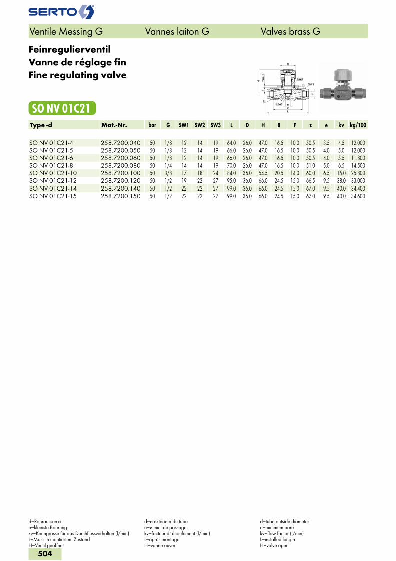
FeinregulierventilVanne de réglage finFine regulating valve
SO NV 01C21Type -d Mat.-Nr. bar G SW1 SW2 SW3 L D H B F z e kv kg/100 SO NV 01C21-4 258.7200.040 50 1/8 12 14 19 64.0 26.0 47.0 16.5 10.0 50.5 3.5 4.5 12.000SO NV 01C21-5 258.7200.050 50 1/8 12 14 19 66.0 26.0 47.0 16.5 10.0 50.5 4.0 5.0 12.000SO NV 01C21-6 258.7200.060 50 1/8 12 14 19 66.0 26.0 47.0 16.5 10.0 50.5 4.0 5.5 11.800SO NV 01C21-8 258.7200.080 50 1/4 14 14 19 70.0 26.0 47.0 16.5 10.0 51.0 5.0 6.5 14.500SO NV 01C21-10 258.7200.100 50 3/8 17 18 24 84.0 36.0 54.5 20.5 14.0 60.0 6.5 15.0 25.800SO NV 01C21-12 258.7200.120 50 1/2 19 22 27 95.0 36.0 66.0 24.5 15.0 66.5 9.5 38.0 33.000SO NV 01C21-14 258.7200.140 50 1/2 22 22 27 99.0 36.0 66.0 24.5 15.0 67.0 9.5 40.0 34.400SO NV 01C21-15 258.7200.150 50 1/2 22 22 27 99.0 36.0 66.0 24.5 15.0 67.0 9.5 40.0 34.600
Ventile Messing G Vannes laiton G Valves brass G
d=Rohraussen-øe=kleinste Bohrungkv=Kenngrösse für das Durchflussverhalten (l/min)L=Mass in montiertem ZustandH=Ventil geöffnet
d=ø extérieur du tubee=ø-min. de passagekv=facteur d´écoulement (l/min)L=après montageH=vanne ouvert
d=tube outside diametere=minimum borekv=flow factor (l/min)L=installed lengthH=valve open
504
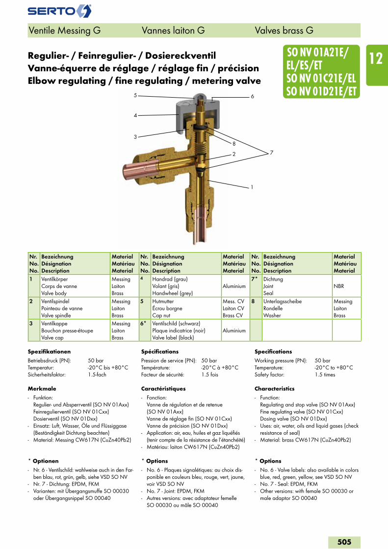
2
6
1
3
4
5
7
8
SO NV 01A21E/ EL/ES/ET SO NV 01C21E/EL SO NV 01D21E/ET
Regulier- / Feinregulier- / DosiereckventilVanne-équerre de réglage / réglage fin / précisionElbow regulating / fine regulating / metering valve
Spezifikationen
Betriebsdruck (PN): 50 barTemperatur: -20°C bis +80°CSicherheitsfaktor: 1.5-fach
Merkmale
- Funktion: Regulier- und Absperrventil (SO NV 01Axx) Feinregulierventil (SO NV 01Cxx) Dosierventil (SO NV 01Dxx)
- Einsatz: Luft, Wasser, Öle und Flüssiggase (Beständigkeit Dichtung beachten)
- Material: Messing CW617N (CuZn40Pb2)
* Optionen
- Nr. 6 - Ventilschild: wahlweise auch in den Far-ben blau, rot, grün, gelb, siehe VSD SO NV
- Nr. 7 - Dichtung: EPDM, FKM- Varianten: mit Übergangsmuffe SO 00030
oder Übergangsnippel SO 00040
Spécifications
Pression de service (PN): 50 barTempérature: -20°C à +80°CFacteur de sécurité: 1.5 fois
Caractéristiques
- Fonction: Vanne de régulation et de retenue (SO NV 01Axx) Vanne de réglage fin (SO NV 01Cxx) Vanne de précision (SO NV 01Dxx)
- Application: air, eau, huiles et gaz liquéfiés (tenir compte de la résistance de l’étanchéité)
- Matériau: laiton CW617N (CuZn40Pb2)
* Options
- No. 6 - Plaques signalétiques: au choix dis-ponible en couleurs bleu, rouge, vert, jaune, voir VSD SO NV
- No. 7 - Joint: EPDM, FKM- Autres versions: avec adaptateur femelle
SO 00030 ou mâle SO 00040
Specifications
Working pressure (PN): 50 barTemperature: -20°C to +80°CSafety factor: 1.5 times
Characteristics
- Function: Regulating and stop valve (SO NV 01Axx) Fine regulating valve (SO NV 01Cxx) Dosing valve (SO NV 01Dxx)
- Uses: air, water, oils and liquid gases (check resistance of seal)
- Material: brass CW617N (CuZn40Pb2)
* Options
- No. 6 - Valve labels: also available in colors blue, red, green, yellow, see VSD SO NV
- No. 7 - Seal: EPDM, FKM- Other versions: with female SO 00030 or
male adaptor SO 00040
Ventile Messing G Vannes laiton G Valves brass G
Nr.No.No.
BezeichnungDésignationDescription
MaterialMatériauMaterial
Nr.No.No.
BezeichnungDésignationDescription
MaterialMatériauMaterial
Nr.No.No.
BezeichnungDésignationDescription
MaterialMatériauMaterial
1 VentilkörperCorps de vanneValve body
MessingLaitonBrass
4 Handrad (grau)Volant (gris)Handwheel (grey)
Aluminium7* Dichtung
JointSeal
NBR
2 VentilspindelPointeau de vanneValve spindle
MessingLaitonBrass
5 HutmutterÉcrou borgneCap nut
Mess. CVLaiton CVBrass CV
8 UnterlagsscheibeRondelleWasher
MessingLaitonBrass
3 VentilkappeBouchon presse-étoupeValve cap
MessingLaitonBrass
6* Ventilschild (schwarz)Plaque indicatrice (noir)Valve label (black)
Aluminium
505
12
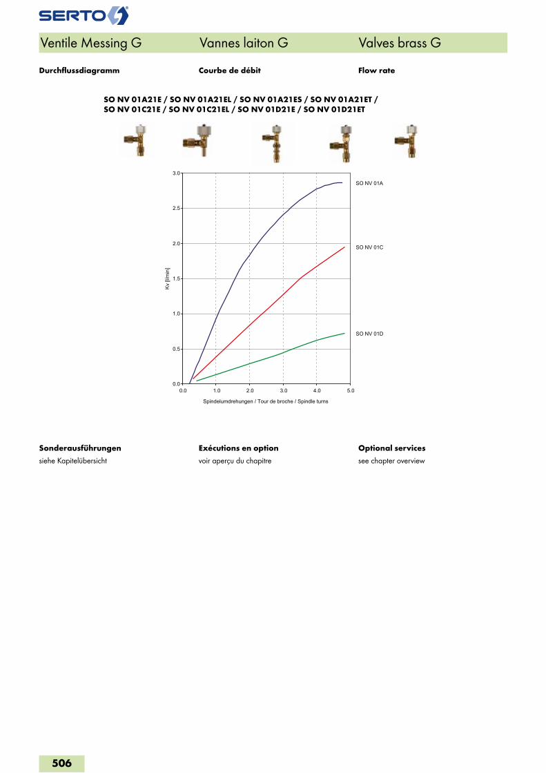
SO NV 01A21E / SO NV 01A21EL / SO NV 01A21ES / SO NV 01A21ET / SO NV 01C21E / SO NV 01C21EL / SO NV 01D21E / SO NV 01D21ET
Ventile Messing G Vannes laiton G Valves brass G
Exécutions en option
voir aperçu du chapitre
Optional services
see chapter overview
Sonderausführungen
siehe Kapitelübersicht
Courbe de débit Flow rateDurchflussdiagramm
0.0
0.5
1.0
1.5
2.0
2.5
3.0
0.0 1.0 2.0 3.0 4.0 5.0
Kv [l
/min
]
Spindelumdrehungen / Tour de broche / Spindle turns
SO NV 01A
SO NV 01C
SO NV 01D
506
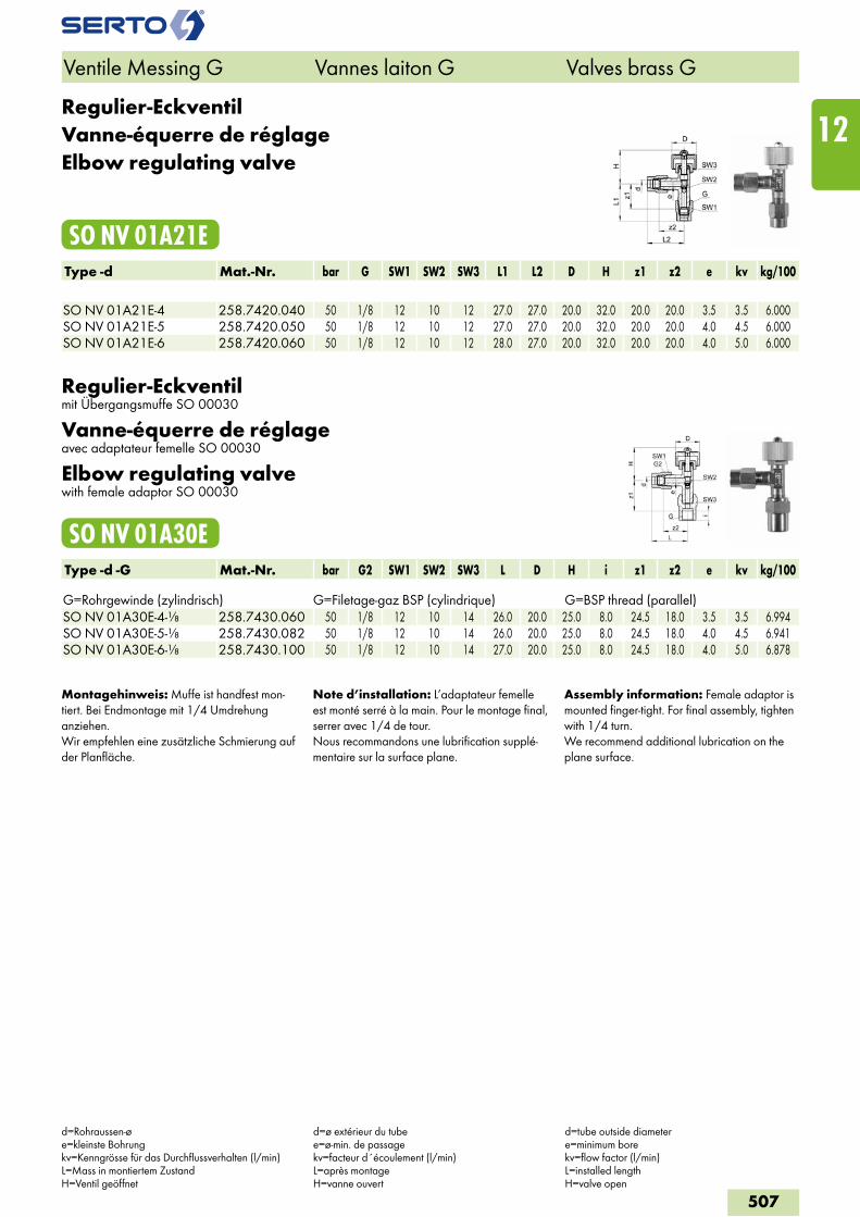
Regulier-EckventilVanne-équerre de réglageElbow regulating valve
SO NV 01A21EType -d Mat.-Nr. bar G SW1 SW2 SW3 L1 L2 D H z1 z2 e kv kg/100 SO NV 01A21E-4 258.7420.040 50 1/8 12 10 12 27.0 27.0 20.0 32.0 20.0 20.0 3.5 3.5 6.000SO NV 01A21E-5 258.7420.050 50 1/8 12 10 12 27.0 27.0 20.0 32.0 20.0 20.0 4.0 4.5 6.000SO NV 01A21E-6 258.7420.060 50 1/8 12 10 12 28.0 27.0 20.0 32.0 20.0 20.0 4.0 5.0 6.000
Regulier-Eckventilmit Übergangsmuffe SO 00030
Vanne-équerre de réglageavec adaptateur femelle SO 00030
Elbow regulating valvewith female adaptor SO 00030
SO NV 01A30EType -d -G Mat.-Nr. bar G2 SW1 SW2 SW3 L D H i z1 z2 e kv kg/100 G=Rohrgewinde (zylindrisch) G=Filetage-gaz BSP (cylindrique) G=BSP thread (parallel)SO NV 01A30E-4-1/8 258.7430.060 50 1/8 12 10 14 26.0 20.0 25.0 8.0 24.5 18.0 3.5 3.5 6.994SO NV 01A30E-5-1/8 258.7430.082 50 1/8 12 10 14 26.0 20.0 25.0 8.0 24.5 18.0 4.0 4.5 6.941SO NV 01A30E-6-1/8 258.7430.100 50 1/8 12 10 14 27.0 20.0 25.0 8.0 24.5 18.0 4.0 5.0 6.878
Montagehinweis: Muffe ist handfest mon-tiert. Bei Endmontage mit 1/4 Umdrehung anziehen.Wir empfehlen eine zusätzliche Schmierung auf der Planfläche.
Note d’installation: L’adaptateur femelle est monté serré à la main. Pour le montage final, serrer avec 1/4 de tour.Nous recommandons une lubrification supplé-mentaire sur la surface plane.
Assembly information: Female adaptor is mounted finger-tight. For final assembly, tighten with 1/4 turn.We recommend additional lubrication on the plane surface.
Ventile Messing G Vannes laiton G Valves brass G
d=Rohraussen-øe=kleinste Bohrungkv=Kenngrösse für das Durchflussverhalten (l/min)L=Mass in montiertem ZustandH=Ventil geöffnet
d=ø extérieur du tubee=ø-min. de passagekv=facteur d´écoulement (l/min)L=après montageH=vanne ouvert
d=tube outside diametere=minimum borekv=flow factor (l/min)L=installed lengthH=valve open
507
12
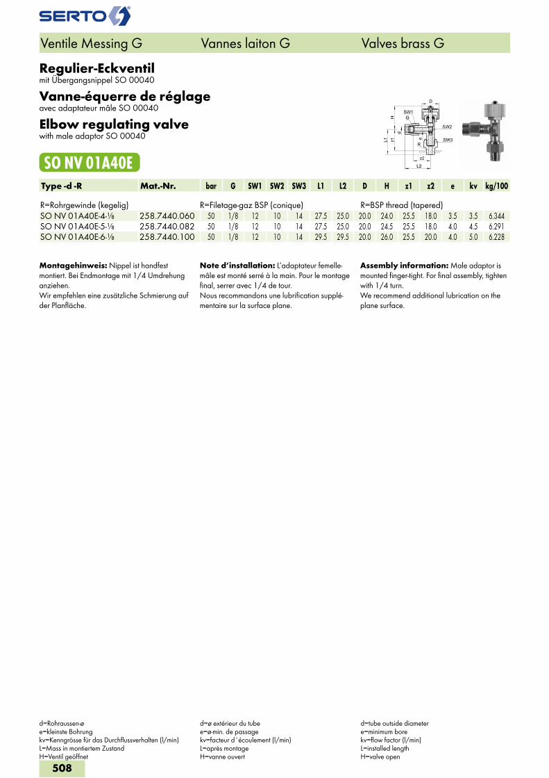
Regulier-Eckventilmit Übergangsnippel SO 00040
Vanne-équerre de réglageavec adaptateur mâle SO 00040
Elbow regulating valvewith male adaptor SO 00040
SO NV 01A40EType -d -R Mat.-Nr. bar G SW1 SW2 SW3 L1 L2 D H z1 z2 e kv kg/100 R=Rohrgewinde (kegelig) R=Filetage-gaz BSP (conique) R=BSP thread (tapered)SO NV 01A40E-4-1/8 258.7440.060 50 1/8 12 10 14 27.5 25.0 20.0 24.0 25.5 18.0 3.5 3.5 6.344SO NV 01A40E-5-1/8 258.7440.082 50 1/8 12 10 14 27.5 25.0 20.0 24.5 25.5 18.0 4.0 4.5 6.291SO NV 01A40E-6-1/8 258.7440.100 50 1/8 12 10 14 29.5 29.5 20.0 26.0 25.5 20.0 4.0 5.0 6.228
Montagehinweis: Nippel ist handfest montiert. Bei Endmontage mit 1/4 Umdrehung anziehen.Wir empfehlen eine zusätzliche Schmierung auf der Planfläche.
Note d’installation: L’adaptateur femelle-mâle est monté serré à la main. Pour le montage final, serrer avec 1/4 de tour.Nous recommandons une lubrification supplé-mentaire sur la surface plane.
Assembly information: Male adaptor is mounted finger-tight. For final assembly, tighten with 1/4 turn.We recommend additional lubrication on the plane surface.
Ventile Messing G Vannes laiton G Valves brass G
d=Rohraussen-øe=kleinste Bohrungkv=Kenngrösse für das Durchflussverhalten (l/min)L=Mass in montiertem ZustandH=Ventil geöffnet
d=ø extérieur du tubee=ø-min. de passagekv=facteur d´écoulement (l/min)L=après montageH=vanne ouvert
d=tube outside diametere=minimum borekv=flow factor (l/min)L=installed lengthH=valve open
508
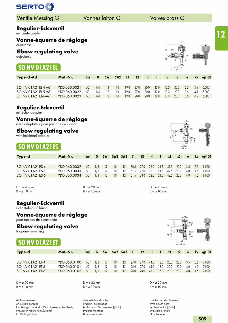
Regulier-Eckventilmit Einstellzapfen
Vanne-équerre de réglageorientable
Elbow regulating valveadjustable
SO NV 01A21ELType -d -Ad Mat.-Nr. bar G SW1 SW2 L1 L2 D H b z e kv kg/100 SO NV 01A21EL-4-A6 YDD.060.0021 50 1/8 12 10 19.0 27.0 20.0 32.0 13.0 20.0 3.5 3.5 5.000SO NV 01A21EL-5-A6 YDD.060.0022 50 1/8 12 10 19.0 27.0 20.0 32.0 13.0 20.0 3.5 4.5 5.000SO NV 01A21EL-6-A6 YDD.060.0023 50 1/8 12 10 19.0 28.0 20.0 32.0 13.0 20.0 3.5 4.5 5.000
Regulier-Eckventilmit Schottadapter
Vanne-équerre de réglageavec adaptateur pour passage de cloison
Elbow regulating valvewith bulkhead adaptor
SO NV 01A21ESType -d Mat.-Nr. bar G SW1 SW2 SW3 L1 L2 H F z1 z2 e kv kg/100 SO NV 01A21ES-4 YDD.060.0032 50 1/8 12 10 12 50.5 27.0 32.0 21.5 42.5 20.0 3.5 3.5 8.000SO NV 01A21ES-5 YDD.060.0033 50 1/8 12 10 12 51.5 27.0 32.0 21.5 42.5 20.0 4.0 4.5 8.000SO NV 01A21ES-6 YDD.060.0034 50 1/8 12 10 12 51.5 28.0 32.0 21.5 42.5 20.0 4.0 4.5 8.000
D = ø 20 mm B = ø 10 mm
D = ø 20 mmB = ø 10 mm
D = ø 20 mm B = ø 10 mm
Regulier-EckventilSchalttafelausführung
Vanne-équerre de réglagepour tableau de commande
Elbow regulating valvefor panel mounting
SO NV 01A21ETType -d Mat.-Nr. bar G SW1 SW2 SW3 L1 L2 H F z1 z2 e kv kg/100 SO NV 01A21ET-4 YDD.060.0100 50 1/8 12 10 12 27.0 27.0 44.0 18.0 20.0 20.0 3.5 3.5 7.000SO NV 01A21ET-5 YDD.060.0101 50 1/8 12 10 12 28.0 27.0 45.0 18.0 20.0 20.0 4.0 4.5 7.000SO NV 01A21ET-6 YDD.060.0102 50 1/8 12 10 12 28.0 28.0 46.0 16.0 20.0 20.0 4.0 4.5 7.000
D = ø 20 mm B = ø 10 mm
D = ø 20 mmB = ø 10 mm
D = ø 20 mm B = ø 10 mm
Ventile Messing G Vannes laiton G Valves brass G
d=Rohraussen-øe=kleinste Bohrungkv=Kenngrösse für das Durchflussverhalten (l/min)L=Mass in montiertem ZustandH=Ventil geöffnet
d=ø extérieur du tubee=ø-min. de passagekv=facteur d´écoulement (l/min)L=après montageH=vanne ouvert
d=tube outside diametere=minimum borekv=flow factor (l/min)L=installed lengthH=valve open
509
12
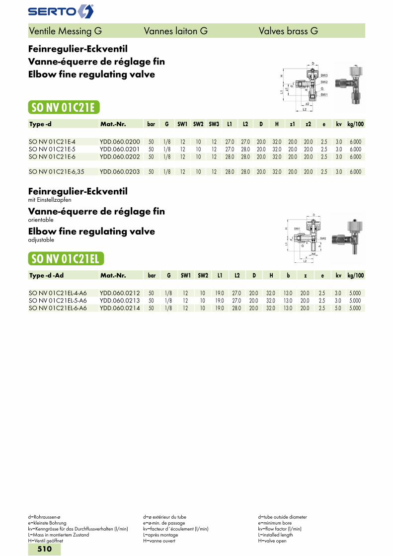
Feinregulier-EckventilVanne-équerre de réglage finElbow fine regulating valve
SO NV 01C21EType -d Mat.-Nr. bar G SW1 SW2 SW3 L1 L2 D H z1 z2 e kv kg/100 SO NV 01C21E-4 YDD.060.0200 50 1/8 12 10 12 27.0 27.0 20.0 32.0 20.0 20.0 2.5 3.0 6.000SO NV 01C21E-5 YDD.060.0201 50 1/8 12 10 12 27.0 28.0 20.0 32.0 20.0 20.0 2.5 3.0 6.000SO NV 01C21E-6 YDD.060.0202 50 1/8 12 10 12 28.0 28.0 20.0 32.0 20.0 20.0 2.5 3.0 6.000 SO NV 01C21E-6,35 YDD.060.0203 50 1/8 12 10 12 28.0 28.0 20.0 32.0 20.0 20.0 2.5 3.0 6.000
Feinregulier-Eckventilmit Einstellzapfen
Vanne-équerre de réglage finorientable
Elbow fine regulating valveadjustable
SO NV 01C21ELType -d -Ad Mat.-Nr. bar G SW1 SW2 L1 L2 D H b z e kv kg/100 SO NV 01C21EL-4-A6 YDD.060.0212 50 1/8 12 10 19.0 27.0 20.0 32.0 13.0 20.0 2.5 3.0 5.000SO NV 01C21EL-5-A6 YDD.060.0213 50 1/8 12 10 19.0 27.0 20.0 32.0 13.0 20.0 2.5 3.0 5.000SO NV 01C21EL-6-A6 YDD.060.0214 50 1/8 12 10 19.0 28.0 20.0 32.0 13.0 20.0 2.5 5.0 5.000
Ventile Messing G Vannes laiton G Valves brass G
d=Rohraussen-øe=kleinste Bohrungkv=Kenngrösse für das Durchflussverhalten (l/min)L=Mass in montiertem ZustandH=Ventil geöffnet
d=ø extérieur du tubee=ø-min. de passagekv=facteur d´écoulement (l/min)L=après montageH=vanne ouvert
d=tube outside diametere=minimum borekv=flow factor (l/min)L=installed lengthH=valve open
510
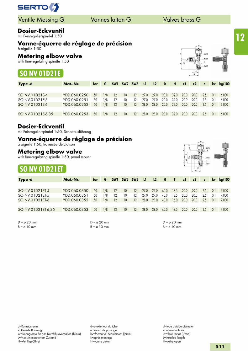
Dosier-Eckventilmit Feinregulierspindel 1:50
Vanne-équerre de réglage de précisionà aiguille 1:50
Metering elbow valvewith fine-regulating spindle 1:50
SO NV 01D21EType -d Mat.-Nr. bar G SW1 SW2 SW3 L1 L2 D H z1 z2 e kv kg/100 SO NV 01D21E-4 YDD.060.0250 50 1/8 12 10 12 27.0 27.0 20.0 32.0 20.0 20.0 2.5 0.1 6.000SO NV 01D21E-5 YDD.060.0251 50 1/8 12 10 12 27.0 27.0 20.0 32.0 20.0 20.0 2.5 0.1 6.000SO NV 01D21E-6 YDD.060.0252 50 1/8 12 10 12 28.0 28.0 20.0 32.0 20.0 20.0 2.5 0.1 6.000 SO NV 01D21E-6,35 YDD.060.0253 50 1/8 12 10 12 28.0 28.0 20.0 32.0 20.0 20.0 2.5 0.1 6.000
Dosier-Eckventilmit Feinregulierspindel 1:50, Schottausführung
Vanne-équerre de réglage de précisionà aiguille 1:50, traversée de cloison
Metering elbow valvewith fine-regulating spindle 1:50, panel mount
SO NV 01D21ETType -d Mat.-Nr. bar G SW1 SW2 SW3 L1 L2 H F z1 z2 e kv kg/100 SO NV 01D21ET-4 YDD.060.0350 50 1/8 12 10 12 27.0 27.0 40.0 18.5 20.0 20.0 2.5 0.1 7.000SO NV 01D21ET-5 YDD.060.0351 50 1/8 12 10 12 27.0 27.0 40.0 18.5 20.0 20.0 2.5 0.1 7.000SO NV 01D21ET-6 YDD.060.0352 50 1/8 12 10 12 28.0 28.0 40.0 16.0 20.0 20.0 2.5 0.1 7.000 SO NV 01D21ET-6,35 YDD.060.0353 50 1/8 12 10 12 28.0 28.0 40.0 18.5 20.0 20.0 2.5 0.1 7.000
D = ø 20 mm B = ø 10 mm
D = ø 20 mm B = ø 10 mm
D = ø 20 mm B = ø 10 mm
Ventile Messing G Vannes laiton G Valves brass G
d=Rohraussen-øe=kleinste Bohrungkv=Kenngrösse für das Durchflussverhalten (l/min)L=Mass in montiertem ZustandH=Ventil geöffnet
d=ø extérieur du tubee=ø-min. de passagekv=facteur d´écoulement (l/min)L=après montageH=vanne ouvert
d=tube outside diametere=minimum borekv=flow factor (l/min)L=installed lengthH=valve open
511
12
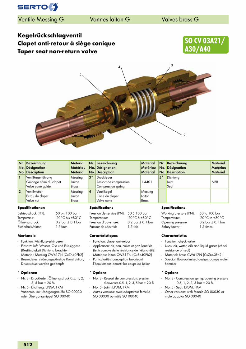
5
3
1
4
2
SO CV 03A21/ A30/A40
KegelrückschlagventilClapet anti-retour à siège coniqueTaper seat non-return valve
Nr.No.No.
BezeichnungDésignationDescription
MaterialMatériauMaterial
Nr.No.No.
BezeichnungDésignationDescription
MaterialMatériauMaterial
Nr.No.No.
BezeichnungDésignationDescription
MaterialMatériauMaterial
1 VentilkegelführungGuidage cône du clapetValve cone guide
MessingLaitonBrass
3* DruckfederRessort de compressionCompression spring
1.44015* Dichtung
JointSeal
NBR
2 VentilmutterÉcrou du clapetValve nut
MessingLaitonBrass
4 VentilkegelCône du clapetValve cone
MessingLaitonBrass
Spezifikationen
Betriebsdruck (PN): 50 bis 100 barTemperatur: -20°C bis +80°CÖffnungsdruck: 0.2 bar ± 0.1 barSicherheitsfaktor: 1.5-fach
Merkmale
- Funktion: Rückflussverhinderer- Einsatz: Luft, Wasser, Öle und Flüssiggase
(Beständigkeit Dichtung beachten)- Material: Messing CW617N (CuZn40Pb2)- Besonderes: strömungsgünstige Konstruktion,
Druckstösse werden gedämpft
* Optionen
- Nr. 3 - Druckfeder: Öffnungsdruck 0.5, 1, 2, 3, 5 bar ± 20 %
- Nr. 5 - Dichtung: EPDM, FKM- Varianten: mit Übergangsmuffe SO 00030
oder Übergangsnippel SO 00040
Spécifications
Pression de service (PN): 50 à 100 barTempérature: -20°C à +80°CPression d‘ouverture: 0.2 bar ± 0.1 barFacteur de sécurité: 1.5 fois
Caractéristiques
- Fonction: clapet anti-retour- Application: air, eau, huiles et gaz liquéfiés
(tenir compte de la résistance de l’étanchéité)- Matériau: laiton CW617N (CuZn40Pb2)- Particularités: conception favorisant
l’écoulement, amortit les coups de bélier
* Options
- No. 3 - Ressort de compression: pression d‘ouverture 0.5, 1, 2, 3, 5 bar ± 20 %
- No. 5 - Joint: EPDM, FKM- Autres versions: avec adaptateur femelle
SO 00030 ou mâle SO 00040
Specifications
Working pressure (PN): 50 to 100 barTemperature: -20°C to +80°COpening pressure: 0.2 bar ± 0.1 barSafety factor: 1.5 times
Characteristics
- Function: check valve- Uses: air, water, oils and liquid gases (check
resistance of seal) - Material: brass CW617N (CuZn40Pb2)- Special: flow-optimised design, damps water
hammer
* Options
- No. 3 - Compression spring: opening pressure 0.5, 1, 2, 3, 5 bar ± 20 %
- No. 5 - Seal: EPDM, FKM- Other versions: with female SO 00030 or
male adaptor SO 00040
Ventile Messing G Vannes laiton G Valves brass G
512
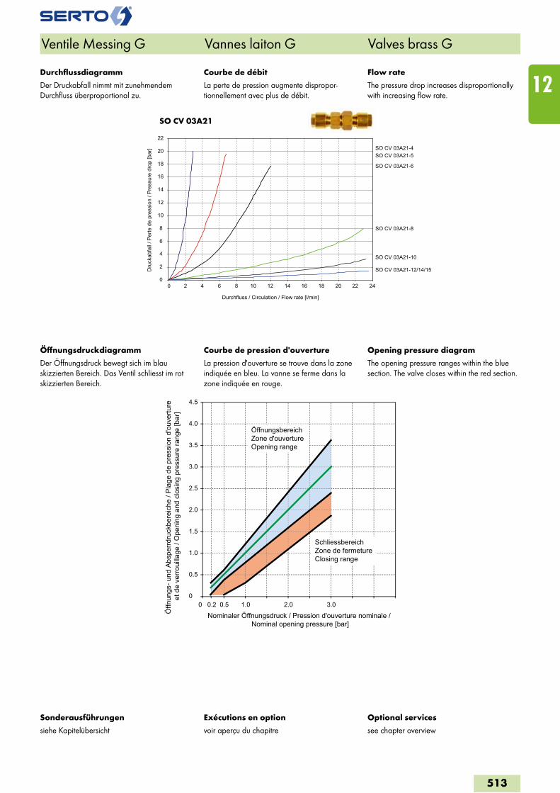
SO CV 03A21
Ventile Messing G Vannes laiton G Valves brass G
Exécutions en option
voir aperçu du chapitre
Optional services
see chapter overview
Sonderausführungen
siehe Kapitelübersicht
0
2
4
6
8
10
12
14
16
18
20
22
0 2 4 6 8 10 12 14 16 18 20 22 24
Durchfluss / Circulation / Flow rate [l/min]
Dru
ckab
fall
/ Per
te d
e pr
essi
on /
Pre
ssur
e dr
op [b
ar] SO CV 03A21-4
SO CV 03A21-5
SO CV 03A21-6
SO CV 03A21-8
SO CV 03A21-10
SO CV 03A21-12/14/15
Courbe de débit
La perte de pression augmente dispropor-tionnellement avec plus de débit.
Courbe de pression d'ouverture
La pression d'ouverture se trouve dans la zone indiquée en bleu. La vanne se ferme dans la zone indiquée en rouge.
Flow rate
The pressure drop increases disproportionally with increasing flow rate.
Opening pressure diagram
The opening pressure ranges within the blue section. The valve closes within the red section.
Durchflussdiagramm
Der Druckabfall nimmt mit zunehmendem Durchfluss überproportional zu.
Öffnungsdruckdiagramm
Der Öffnungsdruck bewegt sich im blau skizzierten Bereich. Das Ventil schliesst im rot skizzierten Bereich.
0
0.5
1.0
1.5
2.0
2.5
3.0
3.5
4.0
4.5
0 0.50.2 1.0 2.0 3.0
Öffn
ungs
- und
Abs
perrd
ruck
bere
iche
/ Pl
age
de p
ress
ion
d'ou
vertu
re
et d
e ve
rroui
llage
/ O
peni
ng a
nd c
losi
ng p
ress
ure
rang
e [b
ar]
Nominaler Öffnungsdruck / Pression d'ouverture nominale / Nominal opening pressure [bar]
ÖffnungsbereichZone d'ouvertureOpening range
SchliessbereichZone de fermetureClosing range
513
12
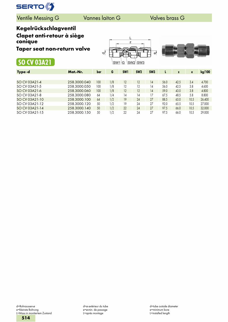
KegelrückschlagventilClapet anti-retour à siège coniqueTaper seat non-return valve
SO CV 03A21Type -d Mat.-Nr. bar G SW1 SW2 SW3 L z e kg/100 SO CV 03A21-4 258.3000.040 100 1/8 12 12 14 56.0 42.5 3.4 4.700SO CV 03A21-5 258.3000.050 100 1/8 12 12 14 56.0 42.5 3.8 4.600SO CV 03A21-6 258.3000.060 100 1/8 12 12 14 59.0 43.0 3.8 4.800SO CV 03A21-8 258.3000.080 64 1/4 14 14 17 67.5 48.5 5.8 8.800SO CV 03A21-10 258.3000.100 64 1/2 19 24 27 88.5 65.0 10.5 26.400SO CV 03A21-12 258.3000.120 50 1/2 19 24 27 92.0 65.5 10.5 27.000SO CV 03A21-14 258.3000.140 50 1/2 22 24 27 97.5 66.0 10.5 32.000SO CV 03A21-15 258.3000.150 50 1/2 22 24 27 97.5 66.0 10.5 29.000
Ventile Messing G Vannes laiton G Valves brass G
d=Rohraussen-øe=kleinste BohrungL=Mass in montiertem Zustand
d=ø extérieur du tubee=ø-min. de passageL=après montage
d=tube outside diametere=minimum boreL=installed length
514
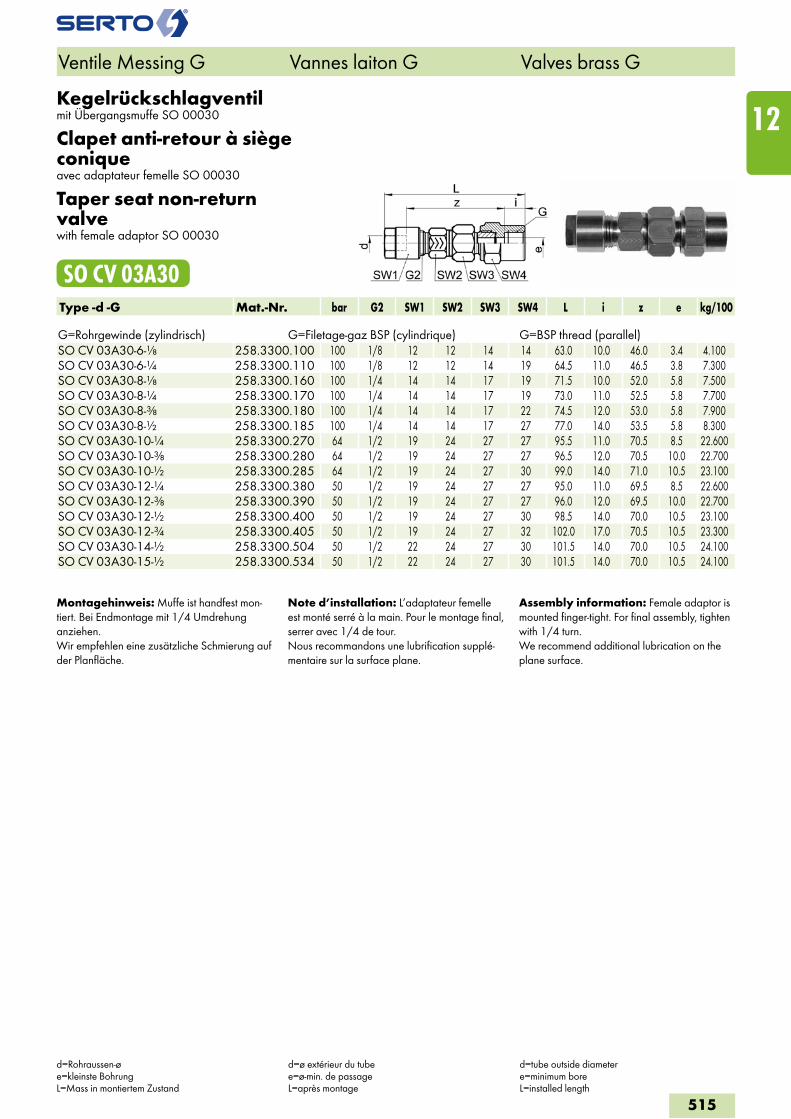
Kegelrückschlagventilmit Übergangsmuffe SO 00030
Clapet anti-retour à siège coniqueavec adaptateur femelle SO 00030
Taper seat non-return valvewith female adaptor SO 00030
SO CV 03A30Type -d -G Mat.-Nr. bar G2 SW1 SW2 SW3 SW4 L i z e kg/100 G=Rohrgewinde (zylindrisch) G=Filetage-gaz BSP (cylindrique) G=BSP thread (parallel)SO CV 03A30-6-1/8 258.3300.100 100 1/8 12 12 14 14 63.0 10.0 46.0 3.4 4.100SO CV 03A30-6-1/4 258.3300.110 100 1/8 12 12 14 19 64.5 11.0 46.5 3.8 7.300SO CV 03A30-8-1/8 258.3300.160 100 1/4 14 14 17 19 71.5 10.0 52.0 5.8 7.500SO CV 03A30-8-1/4 258.3300.170 100 1/4 14 14 17 19 73.0 11.0 52.5 5.8 7.700SO CV 03A30-8-3/8 258.3300.180 100 1/4 14 14 17 22 74.5 12.0 53.0 5.8 7.900SO CV 03A30-8-1/2 258.3300.185 100 1/4 14 14 17 27 77.0 14.0 53.5 5.8 8.300SO CV 03A30-10-1/4 258.3300.270 64 1/2 19 24 27 27 95.5 11.0 70.5 8.5 22.600SO CV 03A30-10-3/8 258.3300.280 64 1/2 19 24 27 27 96.5 12.0 70.5 10.0 22.700SO CV 03A30-10-1/2 258.3300.285 64 1/2 19 24 27 30 99.0 14.0 71.0 10.5 23.100SO CV 03A30-12-1/4 258.3300.380 50 1/2 19 24 27 27 95.0 11.0 69.5 8.5 22.600SO CV 03A30-12-3/8 258.3300.390 50 1/2 19 24 27 27 96.0 12.0 69.5 10.0 22.700SO CV 03A30-12-1/2 258.3300.400 50 1/2 19 24 27 30 98.5 14.0 70.0 10.5 23.100SO CV 03A30-12-3/4 258.3300.405 50 1/2 19 24 27 32 102.0 17.0 70.5 10.5 23.300SO CV 03A30-14-1/2 258.3300.504 50 1/2 22 24 27 30 101.5 14.0 70.0 10.5 24.100SO CV 03A30-15-1/2 258.3300.534 50 1/2 22 24 27 30 101.5 14.0 70.0 10.5 24.100
Montagehinweis: Muffe ist handfest mon-tiert. Bei Endmontage mit 1/4 Umdrehung anziehen.Wir empfehlen eine zusätzliche Schmierung auf der Planfläche.
Note d’installation: L’adaptateur femelle est monté serré à la main. Pour le montage final, serrer avec 1/4 de tour.Nous recommandons une lubrification supplé-mentaire sur la surface plane.
Assembly information: Female adaptor is mounted finger-tight. For final assembly, tighten with 1/4 turn.We recommend additional lubrication on the plane surface.
Ventile Messing G Vannes laiton G Valves brass G
d=Rohraussen-øe=kleinste BohrungL=Mass in montiertem Zustand
d=ø extérieur du tubee=ø-min. de passageL=après montage
d=tube outside diametere=minimum boreL=installed length
515
12
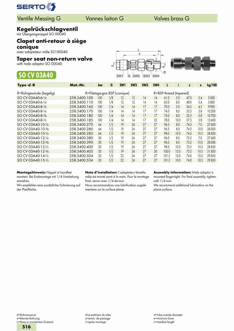
Kegelrückschlagventilmit Übergangsnippel SO 00040
Clapet anti-retour à siège coniqueavec adaptateur mâle SO 00040
Taper seat non-return valvewith male adaptor SO 00040
SO CV 03A40Type -d -R Mat.-Nr. bar G SW1 SW2 SW3 SW4 L i z e kg/100 R=Rohrgewinde (kegelig) R=Filetage-gaz BSP (conique) R=BSP thread (tapered)SO CV 03A40-6-1/8 258.3400.100 100 1/8 12 12 14 14 61.0 5.0 47.0 3.4 5.000SO CV 03A40-6-1/4 258.3400.110 100 1/8 12 12 14 14 65.0 8.0 48.0 3.4 5.800SO CV 03A40-8-1/8 258.3400.160 100 1/4 14 14 17 17 70.0 5.0 54.5 4.5 9.900SO CV 03A40-8-1/4 258.3400.170 100 1/4 14 14 17 17 74.0 8.0 55.5 5.8 10.500SO CV 03A40-8-3/8 258.3400.180 100 1/4 14 14 17 17 74.0 8.0 55.5 5.8 10.700SO CV 03A40-8-1/2 258.3400.185 100 1/4 14 14 17 22 78.0 10.0 57.5 5.8 13.600SO CV 03A40-10-1/4 258.3400.270 64 1/2 19 24 27 27 96.5 8.0 74.5 7.0 27.600SO CV 03A40-10-3/8 258.3400.280 64 1/2 19 24 27 27 96.5 8.0 74.5 10.0 28.000SO CV 03A40-10-1/2 258.3400.285 64 1/2 19 24 27 27 98.0 10.0 74.5 10.5 28.850SO CV 03A40-12-1/4 258.3400.380 50 1/2 19 24 27 27 96.0 8.0 73.5 7.0 27.600SO CV 03A40-12-3/8 258.3400.390 50 1/2 19 24 27 27 96.0 8.0 73.5 10.0 28.000SO CV 03A40-12-1/2 258.3400.400 50 1/2 19 24 27 27 98.0 10.0 73.5 10.5 28.850SO CV 03A40-12-3/4 258.3400.405 50 1/2 19 24 27 30 100.0 12.0 73.5 10.5 31.850SO CV 03A40-14-1/2 258.3400.504 50 1/2 22 24 27 27 101.5 10.0 74.0 10.5 29.850SO CV 03A40-15-1/2 258.3400.534 50 1/2 22 24 27 27 101.5 10.0 74.0 10.5 29.850
Montagehinweis: Nippel ist handfest montiert. Bei Endmontage mit 1/4 Umdrehung anziehen.Wir empfehlen eine zusätzliche Schmierung auf der Planfläche.
Note d’installation: L’adaptateur femelle-mâle est monté serré à la main. Pour le montage final, serrer avec 1/4 de tour.Nous recommandons une lubrification supplé-mentaire sur la surface plane.
Assembly information: Male adaptor is mounted finger-tight. For final assembly, tighten with 1/4 turn.We recommend additional lubrication on the plane surface.
Ventile Messing G Vannes laiton G Valves brass G
d=Rohraussen-øe=kleinste BohrungL=Mass in montiertem Zustand
d=ø extérieur du tubee=ø-min. de passageL=après montage
d=tube outside diametere=minimum boreL=installed length
516
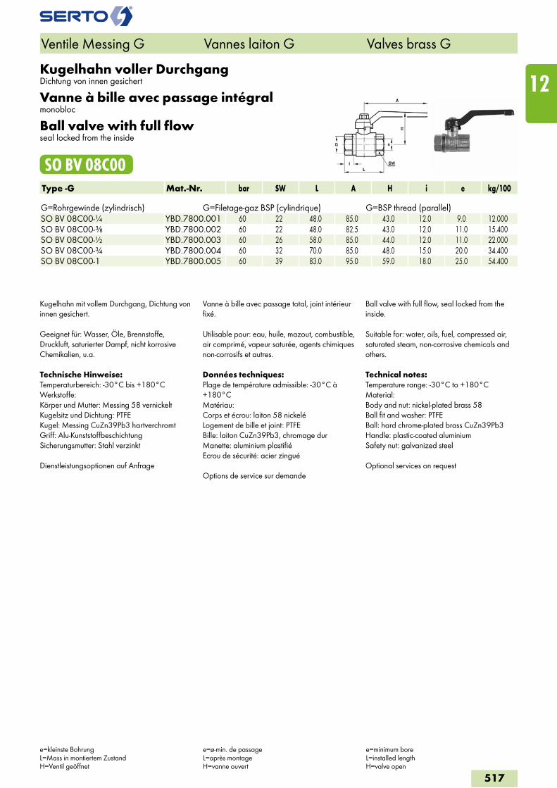
Kugelhahn voller DurchgangDichtung von innen gesichert
Vanne à bille avec passage intégralmonobloc
Ball valve with full flowseal locked from the inside
SO BV 08C00Type -G Mat.-Nr. bar SW L A H i e kg/100 G=Rohrgewinde (zylindrisch) G=Filetage-gaz BSP (cylindrique) G=BSP thread (parallel)SO BV 08C00-1/4 YBD.7800.001 60 22 48.0 85.0 43.0 12.0 9.0 12.000SO BV 08C00-3/8 YBD.7800.002 60 22 48.0 82.5 43.0 12.0 11.0 15.400SO BV 08C00-1/2 YBD.7800.003 60 26 58.0 85.0 44.0 12.0 11.0 22.000SO BV 08C00-3/4 YBD.7800.004 60 32 70.0 85.0 48.0 15.0 20.0 34.400SO BV 08C00-1 YBD.7800.005 60 39 83.0 95.0 59.0 18.0 25.0 54.400
Kugelhahn mit vollem Durchgang, Dichtung von innen gesichert.
Geeignet für: Wasser, Öle, Brennstoffe, Druckluft, saturierter Dampf, nicht korrosive Chemikalien, u.a.
Technische Hinweise:Temperaturbereich: -30°C bis +180°CWerkstoffe:Körper und Mutter: Messing 58 vernickeltKugelsitz und Dichtung: PTFEKugel: Messing CuZn39Pb3 hartverchromtGriff: Alu-KunststoffbeschichtungSicherungsmutter: Stahl verzinkt
Dienstleistungsoptionen auf Anfrage
Vanne à bille avec passage total, joint intérieur fixé.
Utilisable pour: eau, huile, mazout, combustible, air comprimé, vapeur saturée, agents chimiques non-corrosifs et autres.
Données techniques:Plage de température admissible: -30°C à +180°CMatériau:Corps et écrou: laiton 58 nickeléLogement de bille et joint: PTFEBille: laiton CuZn39Pb3, chromage durManette: aluminium plastifiéEcrou de sécurité: acier zingué
Options de service sur demande
Ball valve with full flow, seal locked from the inside.
Suitable for: water, oils, fuel, compressed air, saturated steam, non-corrosive chemicals and others.
Technical notes:Temperature range: -30°C to +180°CMaterial:Body and nut: nickel-plated brass 58Ball fit and washer: PTFEBall: hard chrome-plated brass CuZn39Pb3Handle: plastic-coated aluminiumSafety nut: galvanized steel
Optional services on request
Ventile Messing G Vannes laiton G Valves brass G
e=kleinste BohrungL=Mass in montiertem ZustandH=Ventil geöffnet
e=ø-min. de passageL=après montageH=vanne ouvert
e=minimum boreL=installed lengthH=valve open
517
12
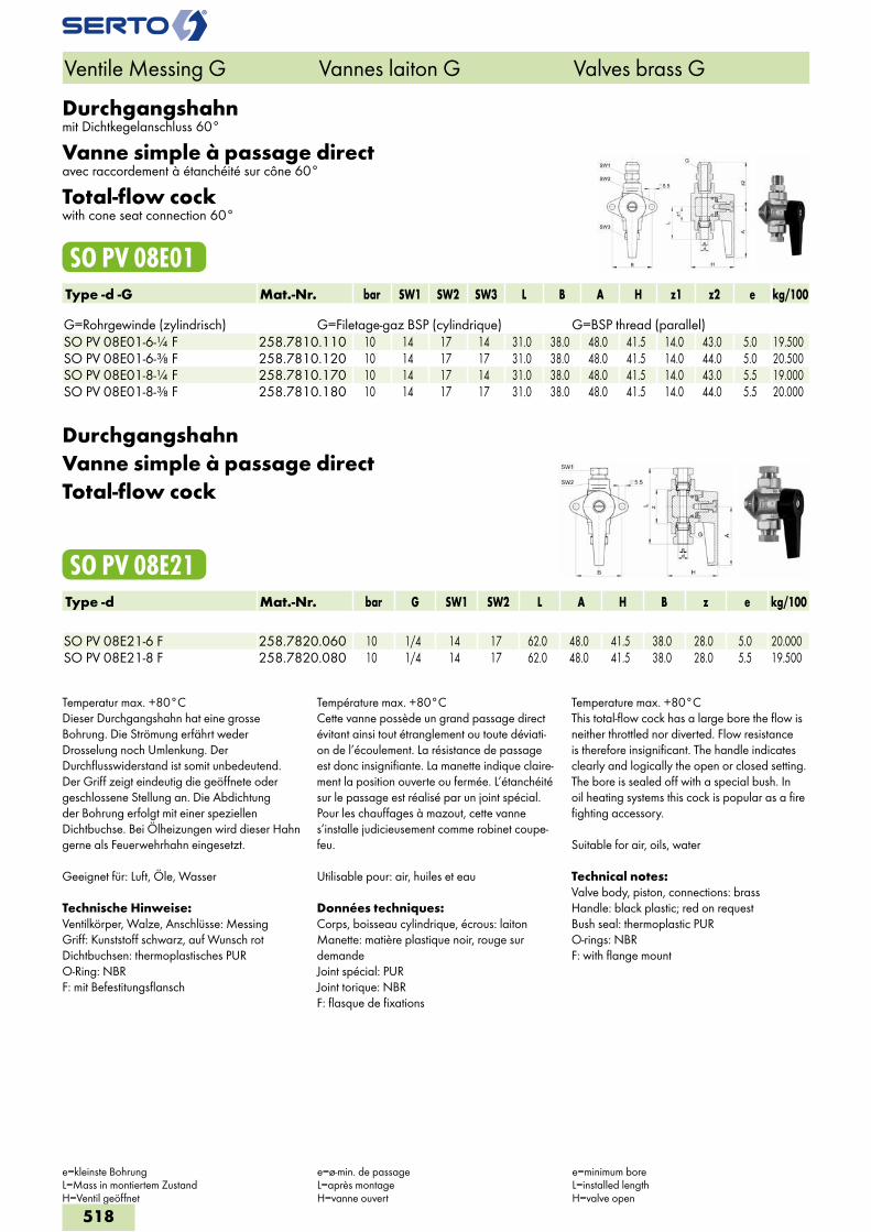
Durchgangshahnmit Dichtkegelanschluss 60°
Vanne simple à passage directavec raccordement à étanchéité sur cône 60°
Total-flow cockwith cone seat connection 60°
SO PV 08E01Type -d -G Mat.-Nr. bar SW1 SW2 SW3 L B A H z1 z2 e kg/100 G=Rohrgewinde (zylindrisch) G=Filetage-gaz BSP (cylindrique) G=BSP thread (parallel)SO PV 08E01-6-1/4 F 258.7810.110 10 14 17 14 31.0 38.0 48.0 41.5 14.0 43.0 5.0 19.500SO PV 08E01-6-3/8 F 258.7810.120 10 14 17 17 31.0 38.0 48.0 41.5 14.0 44.0 5.0 20.500SO PV 08E01-8-1/4 F 258.7810.170 10 14 17 14 31.0 38.0 48.0 41.5 14.0 43.0 5.5 19.000SO PV 08E01-8-3/8 F 258.7810.180 10 14 17 17 31.0 38.0 48.0 41.5 14.0 44.0 5.5 20.000
DurchgangshahnVanne simple à passage directTotal-flow cock
SO PV 08E21Type -d Mat.-Nr. bar G SW1 SW2 L A H B z e kg/100 SO PV 08E21-6 F 258.7820.060 10 1/4 14 17 62.0 48.0 41.5 38.0 28.0 5.0 20.000SO PV 08E21-8 F 258.7820.080 10 1/4 14 17 62.0 48.0 41.5 38.0 28.0 5.5 19.500
Temperatur max. +80°CDieser Durchgangshahn hat eine grosse Bohrung. Die Strömung erfährt weder Drosselung noch Umlenkung. Der Durchflusswiderstand ist somit unbedeutend. Der Griff zeigt eindeutig die geöffnete oder geschlossene Stellung an. Die Abdichtung der Bohrung erfolgt mit einer speziellen Dichtbuchse. Bei Ölheizungen wird dieser Hahn gerne als Feuerwehrhahn eingesetzt.
Geeignet für: Luft, Öle, Wasser
Technische Hinweise:Ventilkörper, Walze, Anschlüsse: MessingGriff: Kunststoff schwarz, auf Wunsch rotDichtbuchsen: thermoplastisches PURO-Ring: NBRF: mit Befestitungsflansch
Température max. +80°CCette vanne possède un grand passage direct évitant ainsi tout étranglement ou toute déviati-on de l’écoulement. La résistance de passage est donc insignifiante. La manette indique claire-ment la position ouverte ou fermée. L’étanchéité sur le passage est réalisé par un joint spécial. Pour les chauffages à mazout, cette vanne s’installe judicieusement comme robinet coupe-feu.
Utilisable pour: air, huiles et eau
Données techniques:Corps, boisseau cylindrique, écrous: laitonManette: matière plastique noir, rouge sur demandeJoint spécial: PURJoint torique: NBRF: flasque de fixations
Temperature max. +80°CThis total-flow cock has a large bore the flow is neither throttled nor diverted. Flow resistance is therefore insignificant. The handle indicates clearly and logically the open or closed setting. The bore is sealed off with a special bush. In oil heating systems this cock is popular as a fire fighting accessory.
Suitable for air, oils, water
Technical notes:Valve body, piston, connections: brassHandle: black plastic; red on requestBush seal: thermoplastic PURO-rings: NBRF: with flange mount
Ventile Messing G Vannes laiton G Valves brass G
e=kleinste BohrungL=Mass in montiertem ZustandH=Ventil geöffnet
e=ø-min. de passageL=après montageH=vanne ouvert
e=minimum boreL=installed lengthH=valve open
518
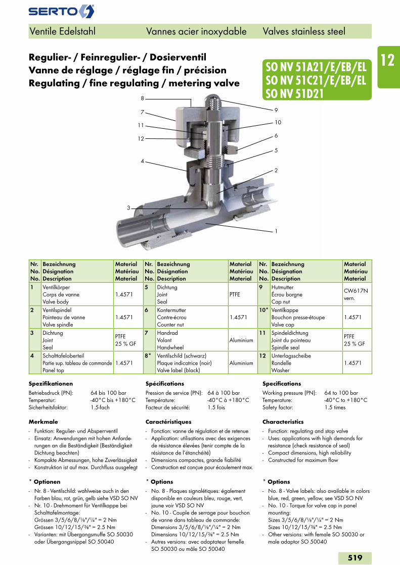
4
3
9
6
1
SO NV 51A21/E/EB/EL SO NV 51C21/E/EB/EL SO NV 51D21
11
12
7
8
10
2
5
Regulier- / Feinregulier- / DosierventilVanne de réglage / réglage fin / précisionRegulating / fine regulating / metering valve
Nr.No.No.
BezeichnungDésignationDescription
MaterialMatériauMaterial
Nr.No.No.
BezeichnungDésignationDescription
MaterialMatériauMaterial
Nr.No.No.
BezeichnungDésignationDescription
MaterialMatériauMaterial
1 VentilkörperCorps de vanneValve body
1.45715 Dichtung
JointSeal
PTFE9 Hutmutter
Écrou borgneCap nut
CW617N vern.
2 VentilspindelPointeau de vanneValve spindle
1.45716 Kontermutter
Contre-écrouCounter nut
1.457110* Ventilkappe
Bouchon presse-étoupeValve cap
1.4571
3 DichtungJointSeal
PTFE25 % GF
7 HandradVolantHandwheel
Aluminium11 Spindeldichtung
Joint du pointeauSpindle seal
PTFE25 % GF
4 SchalttafeloberteilPartie sup. tableau de commandePanel top
1.45718* Ventilschild (schwarz)
Plaque indicatrice (noir)Valve label (black)
Aluminium12 Unterlagsscheibe
RondelleWasher
1.4571
Spezifikationen
Betriebsdruck (PN): 64 bis 100 barTemperatur: -40°C bis +180°CSicherheitsfaktor: 1.5-fach
Merkmale
- Funktion: Regulier- und Absperrventil- Einsatz: Anwendungen mit hohen Anforde-
rungen an die Beständigkeit (Beständigkeit Dichtung beachten)
- Kompakte Abmessungen, hohe Zuverlässigkeit- Konstruktion ist auf max. Durchfluss ausgelegt
* Optionen
- Nr. 8 - Ventilschild: wahlweise auch in den Farben blau, rot, grün, gelb siehe VSD SO NV
- Nr. 10 - Drehmoment für Ventilkappe bei Schalttafelmontage: Grössen 3/5/6/8/"/" = 2 Nm Grössen 10/12/15/" = 2.5 Nm
- Varianten: mit Übergangsmuffe SO 50030 oder Übergangsnippel SO 50040
Spécifications
Pression de service (PN): 64 à 100 barTempérature: -40°C à +180°CFacteur de sécurité: 1.5 fois
Caractéristiques
- Fonction: vanne de régulation et de retenue- Application: utilisations avec des exigences
de résistance élevées (tenir compte de la résistance de l’étanchéité)
- Dimensions compactes, grande fiabilité- Construction est conçue pour écoulement max.
* Options
- No. 8 - Plaques signalétiques: également disponible en couleurs bleu, rouge, vert, jaune voir VSD SO NV
- No. 10 - Couple de serrage pour bouchon de vanne dans tableau de commande: Dimensions 3/5/6/8/"/" = 2 Nm Dimensions 10/12/15/" = 2.5 Nm
- Autres versions: avec adaptateur femelle SO 50030 ou mâle SO 50040
Specifications
Working pressure (PN): 64 to 100 barTemperature: -40°C to +180°CSafety factor: 1.5 times
Characteristics
- Function: regulating and stop valve- Uses: applications with high demands for
resistance (check resistance of seal)- Compact dimensions, high reliability - Constructed for maximum flow
* Options
- No. 8 - Valve labels: also available in colors blue, red, green, yellow, see VSD SO NV
- No. 10 - Torque for valve cap in panel mounting: Sizes 3/5/6/8/"/" = 2 Nm Sizes 10/12/15/" = 2.5 Nm
- Other versions: with female SO 50030 or male adaptor SO 50040
Ventile Edelstahl Vannes acier inoxydable Valves stainless steel
519
12
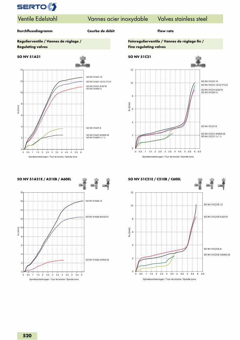
SO NV 51A21 SO NV 51C21
SO NV 51A21E / A21EB / A60EL SO NV 51C21E / C21EB / C60EL
Ventile Edelstahl Vannes acier inoxydable Valves stainless steel
Courbe de débit Flow rateDurchflussdiagramm
Regulierventile / Vannes de réglage /
Regulating valves
Feinregulierventile / Vannes de réglage fin /
Fine regulating valves
00 0.5 1 1.5 2 2.5 3 3.5 4 4.5 5 5.5 6
2
4
6
8
10
12
14
Spindelumdrehungen / Tour de broche / Spindle turns
Kv [l
/min
]
SO NV 51A21-4/5/6/6,35SO NV 51A00-¹/� / ¹/�
SO NV 51A21-8
SO NV 51A21-9,52/10SO NV 51A00-³/�
SO NV 51A21-12/12,7/13,5
SO NV 51A21-15
00 0.5 1 1.5 2 2.5 3 3.5 4 4.5 5 5.5 6
2
4
6
8
10
12
14
16
18
Kv [l
/min
]
Spindelumdrehungen / Tour de broche / Spindle turns
SO NV 51A2E-4/5/6/6,35
SO NV 51A2E-8/9,52/10
SO NV 51A2E-12
Spindelumdrehungen / Tour de broche / Spindle turns
Kv [l
/min
]
0
2
4
6
8
10
12
0 0.5 1 1.5 2 2.5 3 3.5 4 4.5 5 5.5 6 6.5
SO NV 51C21-4/5/6/6,35SO NV 51C21-¹/� / ¹/�
SO NV 51C21-8
SO NV 51C21-9,52/10SO NV 51C00-³/�
SO NV 51C21-12/12,7/13,5SO NV 51C21-15
Spindelumdrehungen / Tour de broche / Spindle turns
Kv [l
/min
]
0
2
4
6
8
10
12
0 0.5 1 1.5 2 2.5 3 3.5 4 4.5 5 5.5 6 6.5
SO NV 51C21E-4/5/6/6,35
SO NV 51C21E-8
SO NV 51C21E-9,52/10
SO NV 51C21E-12
520
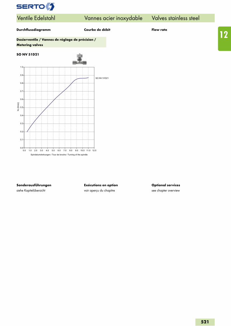
SO NV 51D21
Ventile Edelstahl Vannes acier inoxydable Valves stainless steel
Exécutions en option
voir aperçu du chapitre
Optional services
see chapter overview
Sonderausführungen
siehe Kapitelübersicht
Courbe de débit Flow rateDurchflussdiagramm
Dosierventile / Vannes de réglage de précision /
Metering valves
0.0
0.1
0.2
0.3
0.4
0.5
0.6
0.7
0.8
0.9
1.0
0.0 1.0 2.0 3.0 4.0 5.0 6.0 7.0 8.0 9.0 10.0 11.0 12.0
Kv [l
/min
]
SO NV 51D21
Spindelumdrehungen / Tour de broche / Turning of the spindle
521
12
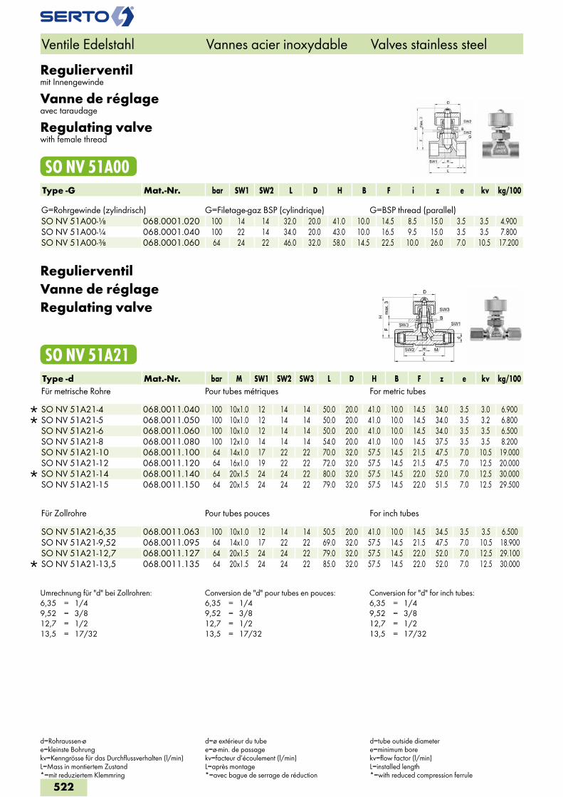
Regulierventilmit Innengewinde
Vanne de réglageavec taraudage
Regulating valvewith female thread
SO NV 51A00Type -G Mat.-Nr. bar SW1 SW2 L D H B F i z e kv kg/100 G=Rohrgewinde (zylindrisch) G=Filetage-gaz BSP (cylindrique) G=BSP thread (parallel)SO NV 51A00-1/8 068.0001.020 100 14 14 32.0 20.0 41.0 10.0 14.5 8.5 15.0 3.5 3.5 4.900SO NV 51A00-1/4 068.0001.040 100 22 14 34.0 20.0 43.0 10.0 16.5 9.5 15.0 3.5 3.5 7.800SO NV 51A00-3/8 068.0001.060 64 24 22 46.0 32.0 58.0 14.5 22.5 10.0 26.0 7.0 10.5 17.200
RegulierventilVanne de réglageRegulating valve
SO NV 51A21Type -d Mat.-Nr. bar M SW1 SW2 SW3 L D H B F z e kv kg/100Für metrische Rohre Pour tubes métriques For metric tubes
SO NV 51A21-4 068.0011.040 100 10x1.0 12 14 14 50.0 20.0 41.0 10.0 14.5 34.0 3.5 3.0 6.900 SO NV 51A21-5 068.0011.050 100 10x1.0 12 14 14 50.0 20.0 41.0 10.0 14.5 34.0 3.5 3.2 6.800 SO NV 51A21-6 068.0011.060 100 10x1.0 12 14 14 50.0 20.0 41.0 10.0 14.5 34.0 3.5 3.5 6.500 SO NV 51A21-8 068.0011.080 100 12x1.0 14 14 14 54.0 20.0 41.0 10.0 14.5 37.5 3.5 3.5 8.200 SO NV 51A21-10 068.0011.100 64 14x1.0 17 22 22 70.0 32.0 57.5 14.5 21.5 47.5 7.0 10.5 19.000 SO NV 51A21-12 068.0011.120 64 16x1.0 19 22 22 72.0 32.0 57.5 14.5 21.5 47.5 7.0 12.5 20.000
SO NV 51A21-14 068.0011.140 64 20x1.5 24 24 22 80.0 32.0 57.5 14.5 22.0 52.0 7.0 12.5 30.000 SO NV 51A21-15 068.0011.150 64 20x1.5 24 24 22 79.0 32.0 57.5 14.5 22.0 51.5 7.0 12.5 29.500
Für Zollrohre Pour tubes pouces For inch tubes
SO NV 51A21-6,35 068.0011.063 100 10x1.0 12 14 14 50.5 20.0 41.0 10.0 14.5 34.5 3.5 3.5 6.500 SO NV 51A21-9,52 068.0011.095 64 14x1.0 17 22 22 69.0 32.0 57.5 14.5 21.5 47.5 7.0 10.5 18.900 SO NV 51A21-12,7 068.0011.127 64 20x1.5 24 24 22 79.0 32.0 57.5 14.5 22.0 52.0 7.0 12.5 29.100
SO NV 51A21-13,5 068.0011.135 64 20x1.5 24 24 22 85.0 32.0 57.5 14.5 22.0 52.0 7.0 12.5 30.000
Umrechnung für "d" bei Zollrohren:6,35 = 1/49,52 = 3/812,7 = 1/213,5 = 17/32
Conversion de "d" pour tubes en pouces:6,35 = 1/49,52 = 3/812,7 = 1/213,5 = 17/32
Conversion for "d" for inch tubes:6,35 = 1/49,52 = 3/812,7 = 1/213,5 = 17/32
Ventile Edelstahl Vannes acier inoxydable Valves stainless steel
d=Rohraussen-øe=kleinste Bohrungkv=Kenngrösse für das Durchflussverhalten (l/min)L=Mass in montiertem Zustand*=mit reduziertem Klemmring
d=ø extérieur du tubee=ø-min. de passagekv=facteur d’écoulement (l/min)L=après montage*=avec bague de serrage de réduction
d=tube outside diametere=minimum borekv=flow factor (l/min)L=installed length*=with reduced compression ferrule
522
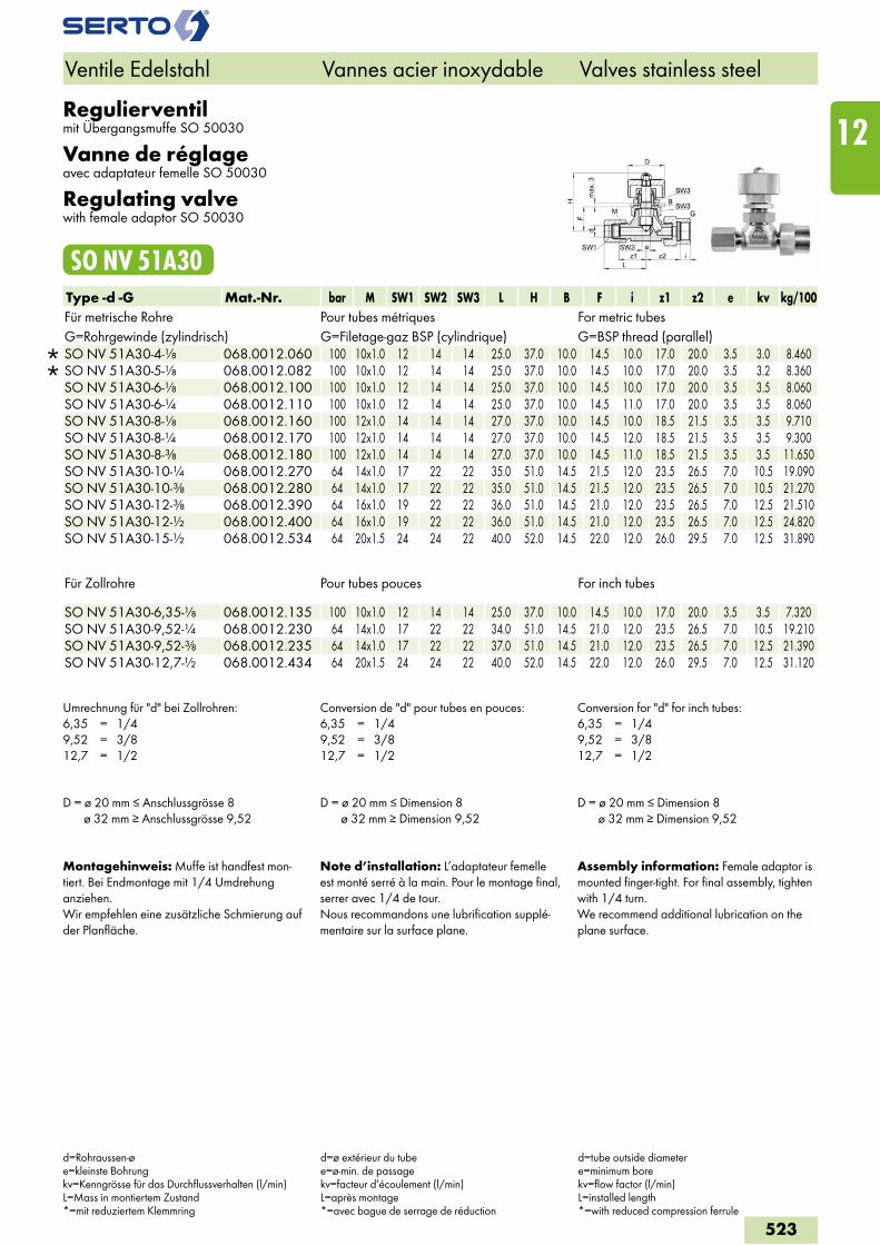
Regulierventilmit Übergangsmuffe SO 50030
Vanne de réglageavec adaptateur femelle SO 50030
Regulating valvewith female adaptor SO 50030
SO NV 51A30Type -d -G Mat.-Nr. bar M SW1 SW2 SW3 L H B F i z1 z2 e kv kg/100Für metrische Rohre Pour tubes métriques For metric tubesG=Rohrgewinde (zylindrisch) G=Filetage-gaz BSP (cylindrique) G=BSP thread (parallel)
SO NV 51A30-4-1/8 068.0012.060 100 10x1.0 12 14 14 25.0 37.0 10.0 14.5 10.0 17.0 20.0 3.5 3.0 8.460 SO NV 51A30-5-1/8 068.0012.082 100 10x1.0 12 14 14 25.0 37.0 10.0 14.5 10.0 17.0 20.0 3.5 3.2 8.360 SO NV 51A30-6-1/8 068.0012.100 100 10x1.0 12 14 14 25.0 37.0 10.0 14.5 10.0 17.0 20.0 3.5 3.5 8.060 SO NV 51A30-6-1/4 068.0012.110 100 10x1.0 12 14 14 25.0 37.0 10.0 14.5 11.0 17.0 20.0 3.5 3.5 8.060 SO NV 51A30-8-1/8 068.0012.160 100 12x1.0 14 14 14 27.0 37.0 10.0 14.5 10.0 18.5 21.5 3.5 3.5 9.710 SO NV 51A30-8-1/4 068.0012.170 100 12x1.0 14 14 14 27.0 37.0 10.0 14.5 12.0 18.5 21.5 3.5 3.5 9.300 SO NV 51A30-8-3/8 068.0012.180 100 12x1.0 14 14 14 27.0 37.0 10.0 14.5 11.0 18.5 21.5 3.5 3.5 11.650 SO NV 51A30-10-1/4 068.0012.270 64 14x1.0 17 22 22 35.0 51.0 14.5 21.5 12.0 23.5 26.5 7.0 10.5 19.090 SO NV 51A30-10-3/8 068.0012.280 64 14x1.0 17 22 22 35.0 51.0 14.5 21.5 12.0 23.5 26.5 7.0 10.5 21.270 SO NV 51A30-12-3/8 068.0012.390 64 16x1.0 19 22 22 36.0 51.0 14.5 21.0 12.0 23.5 26.5 7.0 12.5 21.510 SO NV 51A30-12-1/2 068.0012.400 64 16x1.0 19 22 22 36.0 51.0 14.5 21.0 12.0 23.5 26.5 7.0 12.5 24.820 SO NV 51A30-15-1/2 068.0012.534 64 20x1.5 24 24 22 40.0 52.0 14.5 22.0 12.0 26.0 29.5 7.0 12.5 31.890
Für Zollrohre Pour tubes pouces For inch tubes SO NV 51A30-6,35-1/8 068.0012.135 100 10x1.0 12 14 14 25.0 37.0 10.0 14.5 10.0 17.0 20.0 3.5 3.5 7.320SO NV 51A30-9,52-1/4 068.0012.230 64 14x1.0 17 22 22 34.0 51.0 14.5 21.0 12.0 23.5 26.5 7.0 10.5 19.210SO NV 51A30-9,52-3/8 068.0012.235 64 14x1.0 17 22 22 37.0 51.0 14.5 21.0 12.0 23.5 26.5 7.0 12.5 21.390SO NV 51A30-12,7-1/2 068.0012.434 64 20x1.5 24 24 22 40.0 52.0 14.5 22.0 12.0 26.0 29.5 7.0 12.5 31.120
Umrechnung für "d" bei Zollrohren:6,35 = 1/49,52 = 3/812,7 = 1/2
Conversion de "d" pour tubes en pouces:6,35 = 1/49,52 = 3/812,7 = 1/2
Conversion for "d" for inch tubes:6,35 = 1/49,52 = 3/812,7 = 1/2
D = ø 20 mm ≤ Anschlussgrösse 8 ø 32 mm ≥ Anschlussgrösse 9,52
D = ø 20 mm ≤ Dimension 8 ø 32 mm ≥ Dimension 9,52
D = ø 20 mm ≤ Dimension 8 ø 32 mm ≥ Dimension 9,52
Montagehinweis: Muffe ist handfest mon-tiert. Bei Endmontage mit 1/4 Umdrehung anziehen.Wir empfehlen eine zusätzliche Schmierung auf der Planfläche.
Note d’installation: L’adaptateur femelle est monté serré à la main. Pour le montage final, serrer avec 1/4 de tour.Nous recommandons une lubrification supplé-mentaire sur la surface plane.
Assembly information: Female adaptor is mounted finger-tight. For final assembly, tighten with 1/4 turn.We recommend additional lubrication on the plane surface.
Ventile Edelstahl Vannes acier inoxydable Valves stainless steel
d=Rohraussen-øe=kleinste Bohrungkv=Kenngrösse für das Durchflussverhalten (l/min)L=Mass in montiertem Zustand*=mit reduziertem Klemmring
d=ø extérieur du tubee=ø-min. de passagekv=facteur d’écoulement (l/min)L=après montage*=avec bague de serrage de réduction
d=tube outside diametere=minimum borekv=flow factor (l/min)L=installed length*=with reduced compression ferrule
523
12
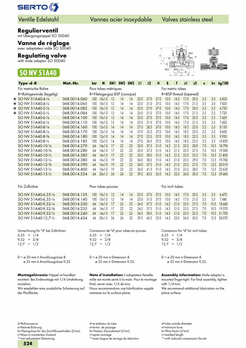
Regulierventilmit Übergangsnippel SO 50040
Vanne de réglageavec adaptateur mâle SO 50040
Regulating valvewith male adaptor SO 50040
SO NV 51A40Type -d -R Mat.-Nr. bar M SW1 SW2 SW3 L1 L2 H B F z1 z2 e kv kg/100Für metrische Rohre Pour tubes métriques For metric tubesR=Rohrgewinde (kegelig) R=Filetage-gaz BSP (conique) R=BSP thread (tapered)
SO NV 51A40-4-1/8 068.0014.060 100 10x1.0 12 14 14 25.0 27.0 37.0 10.0 14.5 17.0 20.5 3.5 3.0 6.850 SO NV 51A40-4-1/4 068.0014.065 100 10x1.0 12 14 14 25.0 31.0 37.0 10.0 14.5 17.0 21.5 3.5 3.0 7.820 SO NV 51A40-5-1/8 068.0014.082 100 10x1.0 12 14 14 25.0 27.0 37.0 10.0 14.5 17.0 20.5 3.5 3.2 6.750 SO NV 51A40-5-1/4 068.0014.084 100 10x1.0 12 14 14 25.0 31.0 37.0 10.0 14.5 17.0 21.5 3.5 3.2 7.720 SO NV 51A40-6-1/8 068.0014.100 100 10x1.0 12 14 14 25.0 27.0 37.0 10.0 14.5 17.0 20.5 3.5 3.5 7.420 SO NV 51A40-6-1/4 068.0014.110 100 10x1.0 12 14 14 25.0 31.0 37.0 10.0 14.5 17.0 21.5 3.5 3.5 7.420 SO NV 51A40-8-1/8 068.0014.160 100 12x1.0 14 14 14 27.0 28.5 37.0 10.0 14.5 18.5 22.0 3.5 3.5 8.130 SO NV 51A40-8-1/4 068.0014.170 100 12x1.0 14 14 14 27.0 32.5 37.0 10.0 14.5 18.5 23.0 3.5 3.5 8.600 SO NV 51A40-8-3/8 068.0014.180 100 12x1.0 14 14 14 27.0 32.5 37.0 10.0 14.5 18.5 22.5 3.5 3.5 9.950 SO NV 51A40-8-1/2 068.0014.185 100 12x1.0 14 14 14 27.0 36.5 37.0 10.0 14.5 18.5 23.5 3.5 3.5 10.850 SO NV 51A40-10-1/4 068.0014.270 64 14x1.0 17 22 22 35.0 37.5 51.0 14.5 21.5 23.5 28.0 7.0 10.5 18.790 SO NV 51A40-10-3/8 068.0014.280 64 14x1.0 17 22 22 35.0 37.5 51.0 14.5 21.5 23.5 27.5 7.0 10.5 19.500 SO NV 51A40-10-1/2 068.0014.285 64 14x1.0 17 22 22 35.0 38.5 51.0 14.5 21.5 23.5 25.5 7.0 10.5 21.850 SO NV 51A40-12-1/4 068.0014.380 64 16x1.0 19 22 22 36.0 38.5 51.0 14.5 21.0 23.5 29.0 7.0 12.5 19.760 SO NV 51A40-12-3/8 068.0014.390 64 16x1.0 19 22 22 36.0 37.5 51.0 14.5 21.0 23.5 27.5 7.0 12.5 20.010 SO NV 51A40-12-1/2 068.0014.400 64 16x1.0 19 22 22 36.0 41.5 51.0 14.5 21.0 23.5 28.5 7.0 12.5 22.620 SO NV 51A40-15-1/2 068.0014.534 64 20x1.5 24 24 22 39.5 43.5 52.0 14.5 22.0 26.0 30.5 7.0 12.5 29.460
Für Zollrohre Pour tubes pouces For inch tubes SO NV 51A40-6,35-1/8 068.0014.135 100 10x1.0 12 14 14 25.0 27.0 37.0 10.0 14.5 17.0 20.5 3.5 3.5 6.470SO NV 51A40-6,35-1/4 068.0014.140 100 10x1.0 12 14 14 25.0 31.0 37.0 10.0 14.5 17.0 21.0 3.5 3.5 7.440SO NV 51A40-9,52-1/4 068.0014.230 64 14x1.0 17 22 22 34.5 37.5 51.0 14.5 21.0 23.5 27.5 7.0 10.5 18.660SO NV 51A40-9,52-3/8 068.0014.235 64 14x1.0 17 22 22 34.5 37.5 51.0 14.5 21.0 23.5 27.5 7.0 10.5 19.370SO NV 51A40-9,52-1/2 068.0014.240 64 14x1.0 17 22 22 34.5 38.5 51.0 14.5 21.0 23.5 25.5 7.0 10.5 21.700SO NV 51A40-12,7-1/2 068.0014.434 64 20x1.5 24 24 22 39.5 43.5 52.0 14.5 22.0 26.0 30.5 7.0 12.5 28.070
Umrechnung für "d" bei Zollrohren:6,35 = 1/49,52 = 3/812,7 = 1/2
Conversion de "d" pour tubes en pouces:6,35 = 1/49,52 = 3/812,7 = 1/2
Conversion for "d" for inch tubes:6,35 = 1/49,52 = 3/812,7 = 1/2
D = ø 20 mm ≤ Anschlussgrösse 8 ø 32 mm ≥ Anschlussgrösse 9,52
D = ø 20 mm ≤ Dimension 8 ø 32 mm ≥ Dimension 9,52
D = ø 20 mm ≤ Dimension 8 ø 32 mm ≥ Dimension 9,52
Montagehinweis: Nippel ist handfest montiert. Bei Endmontage mit 1/4 Umdrehung anziehen.Wir empfehlen eine zusätzliche Schmierung auf der Planfläche.
Note d’installation: L’adaptateur femelle-mâle est monté serré à la main. Pour le montage final, serrer avec 1/4 de tour.Nous recommandons une lubrification supplé-mentaire sur la surface plane.
Assembly information: Male adaptor is mounted finger-tight. For final assembly, tighten with 1/4 turn.We recommend additional lubrication on the plane surface.
Ventile Edelstahl Vannes acier inoxydable Valves stainless steel
d=Rohraussen-øe=kleinste Bohrungkv=Kenngrösse für das Durchflussverhalten (l/min)L=Mass in montiertem Zustand*=mit reduziertem Klemmring
d=ø extérieur du tubee=ø-min. de passagekv=facteur d’écoulement (l/min)L=après montage*=avec bague de serrage de réduction
d=tube outside diametere=minimum borekv=flow factor (l/min)L=installed length*=with reduced compression ferrule
524
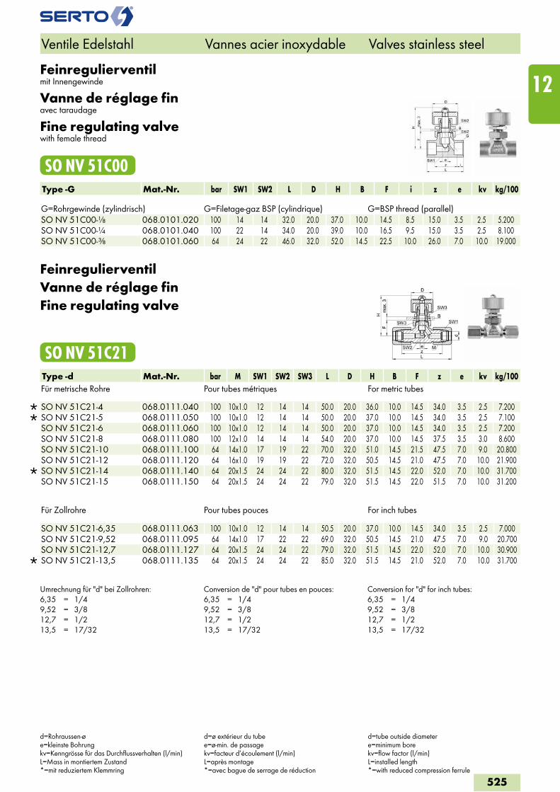
Feinregulierventilmit Innengewinde
Vanne de réglage finavec taraudage
Fine regulating valvewith female thread
SO NV 51C00Type -G Mat.-Nr. bar SW1 SW2 L D H B F i z e kv kg/100 G=Rohrgewinde (zylindrisch) G=Filetage-gaz BSP (cylindrique) G=BSP thread (parallel)SO NV 51C00-1/8 068.0101.020 100 14 14 32.0 20.0 37.0 10.0 14.5 8.5 15.0 3.5 2.5 5.200SO NV 51C00-1/4 068.0101.040 100 22 14 34.0 20.0 39.0 10.0 16.5 9.5 15.0 3.5 2.5 8.100SO NV 51C00-3/8 068.0101.060 64 24 22 46.0 32.0 52.0 14.5 22.5 10.0 26.0 7.0 10.0 19.000
FeinregulierventilVanne de réglage finFine regulating valve
SO NV 51C21Type -d Mat.-Nr. bar M SW1 SW2 SW3 L D H B F z e kv kg/100Für metrische Rohre Pour tubes métriques For metric tubes
SO NV 51C21-4 068.0111.040 100 10x1.0 12 14 14 50.0 20.0 36.0 10.0 14.5 34.0 3.5 2.5 7.200 SO NV 51C21-5 068.0111.050 100 10x1.0 12 14 14 50.0 20.0 37.0 10.0 14.5 34.0 3.5 2.5 7.100 SO NV 51C21-6 068.0111.060 100 10x1.0 12 14 14 50.0 20.0 37.0 10.0 14.5 34.0 3.5 2.5 7.200 SO NV 51C21-8 068.0111.080 100 12x1.0 14 14 14 54.0 20.0 37.0 10.0 14.5 37.5 3.5 3.0 8.600 SO NV 51C21-10 068.0111.100 64 14x1.0 17 19 22 70.0 32.0 51.0 14.5 21.5 47.5 7.0 9.0 20.800 SO NV 51C21-12 068.0111.120 64 16x1.0 19 19 22 72.0 32.0 50.5 14.5 21.0 47.5 7.0 10.0 21.900
SO NV 51C21-14 068.0111.140 64 20x1.5 24 24 22 80.0 32.0 51.5 14.5 22.0 52.0 7.0 10.0 31.700 SO NV 51C21-15 068.0111.150 64 20x1.5 24 24 22 79.0 32.0 51.5 14.5 22.0 51.5 7.0 10.0 31.200
Für Zollrohre Pour tubes pouces For inch tubes
SO NV 51C21-6,35 068.0111.063 100 10x1.0 12 14 14 50.5 20.0 37.0 10.0 14.5 34.0 3.5 2.5 7.000 SO NV 51C21-9,52 068.0111.095 64 14x1.0 17 22 22 69.0 32.0 50.5 14.5 21.0 47.5 7.0 9.0 20.700 SO NV 51C21-12,7 068.0111.127 64 20x1.5 24 24 22 79.0 32.0 51.5 14.5 22.0 52.0 7.0 10.0 30.900
SO NV 51C21-13,5 068.0111.135 64 20x1.5 24 24 22 85.0 32.0 51.5 14.5 21.0 52.0 7.0 10.0 31.700
Umrechnung für "d" bei Zollrohren:6,35 = 1/49,52 = 3/812,7 = 1/213,5 = 17/32
Conversion de "d" pour tubes en pouces:6,35 = 1/49,52 = 3/812,7 = 1/213,5 = 17/32
Conversion for "d" for inch tubes:6,35 = 1/49,52 = 3/812,7 = 1/213,5 = 17/32
Ventile Edelstahl Vannes acier inoxydable Valves stainless steel
d=Rohraussen-øe=kleinste Bohrungkv=Kenngrösse für das Durchflussverhalten (l/min)L=Mass in montiertem Zustand*=mit reduziertem Klemmring
d=ø extérieur du tubee=ø-min. de passagekv=facteur d’écoulement (l/min)L=après montage*=avec bague de serrage de réduction
d=tube outside diametere=minimum borekv=flow factor (l/min)L=installed length*=with reduced compression ferrule
525
12
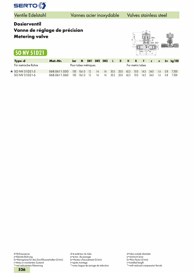
DosierventilVanne de réglage de précisionMetering valve
SO NV 51D21Type -d Mat.-Nr. bar M SW1 SW2 SW3 L D H B F z e kv kg/100Für metrische Rohre Pour tubes métriques For metric tubes
SO NV 51D21-5 068.0611.050 100 10x1.0 12 14 14 50.5 20.0 42.5 10.0 14.5 34.0 1.6 0.8 7.300 SO NV 51D21-6 068.0611.060 100 10x1.0 12 14 14 50.5 20.0 42.5 10.0 14.5 34.0 1.6 0.8 7.300
Ventile Edelstahl Vannes acier inoxydable Valves stainless steel
d=Rohraussen-øe=kleinste Bohrungkv=Kenngrösse für das Durchflussverhalten (l/min)L=Mass in montiertem Zustand*=mit reduziertem Klemmring
d=ø extérieur du tubee=ø-min. de passagekv=facteur d’écoulement (l/min)L=après montage*=avec bague de serrage de réduction
d=tube outside diametere=minimum borekv=flow factor (l/min)L=installed length*=with reduced compression ferrule
526
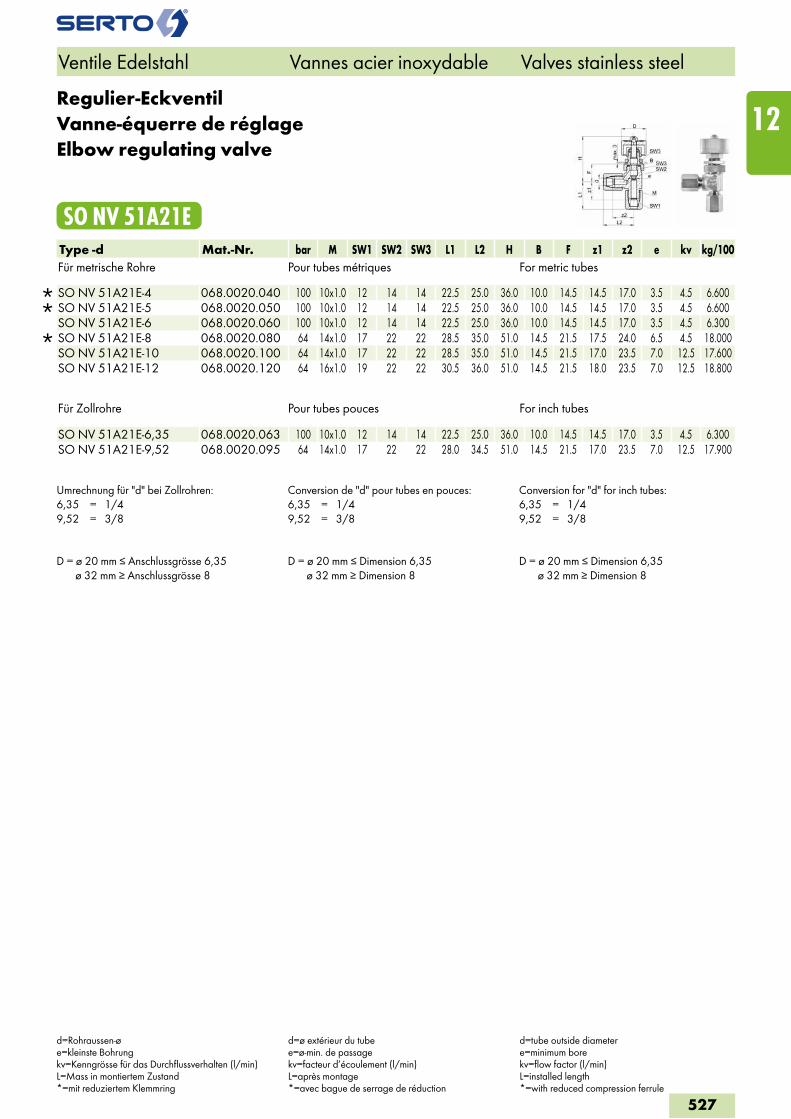
Regulier-EckventilVanne-équerre de réglageElbow regulating valve
SO NV 51A21EType -d Mat.-Nr. bar M SW1 SW2 SW3 L1 L2 H B F z1 z2 e kv kg/100Für metrische Rohre Pour tubes métriques For metric tubes
SO NV 51A21E-4 068.0020.040 100 10x1.0 12 14 14 22.5 25.0 36.0 10.0 14.5 14.5 17.0 3.5 4.5 6.600 SO NV 51A21E-5 068.0020.050 100 10x1.0 12 14 14 22.5 25.0 36.0 10.0 14.5 14.5 17.0 3.5 4.5 6.600 SO NV 51A21E-6 068.0020.060 100 10x1.0 12 14 14 22.5 25.0 36.0 10.0 14.5 14.5 17.0 3.5 4.5 6.300
SO NV 51A21E-8 068.0020.080 64 14x1.0 17 22 22 28.5 35.0 51.0 14.5 21.5 17.5 24.0 6.5 4.5 18.000 SO NV 51A21E-10 068.0020.100 64 14x1.0 17 22 22 28.5 35.0 51.0 14.5 21.5 17.0 23.5 7.0 12.5 17.600 SO NV 51A21E-12 068.0020.120 64 16x1.0 19 22 22 30.5 36.0 51.0 14.5 21.5 18.0 23.5 7.0 12.5 18.800
Für Zollrohre Pour tubes pouces For inch tubes
SO NV 51A21E-6,35 068.0020.063 100 10x1.0 12 14 14 22.5 25.0 36.0 10.0 14.5 14.5 17.0 3.5 4.5 6.300 SO NV 51A21E-9,52 068.0020.095 64 14x1.0 17 22 22 28.0 34.5 51.0 14.5 21.5 17.0 23.5 7.0 12.5 17.900
Umrechnung für "d" bei Zollrohren:6,35 = 1/49,52 = 3/8
Conversion de "d" pour tubes en pouces:6,35 = 1/49,52 = 3/8
Conversion for "d" for inch tubes:6,35 = 1/49,52 = 3/8
D = ø 20 mm ≤ Anschlussgrösse 6,35 ø 32 mm ≥ Anschlussgrösse 8
D = ø 20 mm ≤ Dimension 6,35 ø 32 mm ≥ Dimension 8
D = ø 20 mm ≤ Dimension 6,35 ø 32 mm ≥ Dimension 8
Ventile Edelstahl Vannes acier inoxydable Valves stainless steel
d=Rohraussen-øe=kleinste Bohrungkv=Kenngrösse für das Durchflussverhalten (l/min)L=Mass in montiertem Zustand*=mit reduziertem Klemmring
d=ø extérieur du tubee=ø-min. de passagekv=facteur d’écoulement (l/min)L=après montage*=avec bague de serrage de réduction
d=tube outside diametere=minimum borekv=flow factor (l/min)L=installed length*=with reduced compression ferrule
527
12
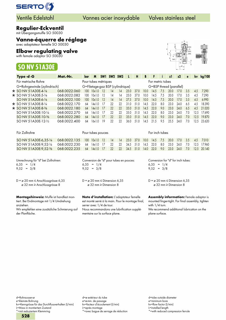
Regulier-Eckventilmit Übergangsmuffe SO 50030
Vanne-équerre de réglageavec adaptateur femelle SO 50030
Elbow regulating valvewith female adaptor SO 50030
SO NV 51A30EType -d -G Mat.-Nr. bar M SW1 SW2 SW3 L H B F i z1 z2 e kv kg/100Für metrische Rohre Pour tubes métriques For metric tubesG=Rohrgewinde (zylindrisch) G=Filetage-gaz BSP (cylindrique) G=BSP thread (parallel)
SO NV 51A30E-4-1/8 068.0022.060 100 10x1.0 12 14 14 25.0 37.0 10.0 14.5 7.5 20.0 17.0 3.5 4.5 7.290 SO NV 51A30E-5-1/8 068.0022.082 100 10x1.0 12 14 14 25.0 37.0 10.0 14.5 7.5 20.0 17.0 3.5 4.5 7.290 SO NV 51A30E-6-1/8 068.0022.100 100 10x1.0 12 14 14 27.5 37.0 10.0 14.5 7.5 20.0 17.0 3.5 4.5 6.990
SO NV 51A30E-8-1/4 068.0022.170 64 14x1.0 17 22 22 31.0 51.0 14.5 22.0 8.0 23.0 24.0 6.5 4.5 18.390 SO NV 51A30E-8-3/8 068.0022.180 64 14x1.0 17 22 22 35.0 51.0 14.5 22.0 9.0 23.0 24.0 6.5 4.5 21.020 SO NV 51A30E-10-1/4 068.0022.270 64 14x1.0 17 22 22 35.0 51.0 14.5 22.0 8.0 23.0 24.0 7.0 12.5 17.690 SO NV 51A30E-10-3/8 068.0022.280 64 14x1.0 17 22 22 35.0 51.0 14.5 22.0 9.0 23.0 24.0 7.0 12.5 19.870 SO NV 51A30E-12-1/2 068.0022.400 64 16x1.0 19 22 22 36.0 51.0 14.5 21.5 9.5 25.5 24.0 7.0 12.5 23.620
Für Zollrohre Pour tubes pouces For inch tubes SO NV 51A30E-6,35-1/8 068.0022.135 100 10x1.0 12 14 14 25.0 37.0 10.0 14.5 7.5 20.0 17.0 3.5 4.5 7.010SO NV 51A30E-9,52-1/4 068.0022.230 64 14x1.0 17 22 22 34.5 51.0 14.5 22.0 8.0 23.0 24.0 7.0 12.5 17.960SO NV 51A30E-9,52-3/8 068.0022.235 64 14x1.0 17 22 22 34.5 51.0 14.0 22.0 9.0 23.0 24.0 7.0 12.5 20.140
Umrechnung für "d" bei Zollrohren:6,35 = 1/49,52 = 3/8
Conversion de "d" pour tubes en pouces:6,35 = 1/49,52 = 3/8
Conversion for "d" for inch tubes:6,35 = 1/49,52 = 3/8
D = ø 20 mm ≤ Anschlussgrösse 6,35 ø 32 mm ≥ Anschlussgrösse 8
D = ø 20 mm ≤ Dimension 6,35 ø 32 mm ≥ Dimension 8
D = ø 20 mm ≤ Dimension 6,35 ø 32 mm ≥ Dimension 8
Montagehinweis: Muffe ist handfest mon-tiert. Bei Endmontage mit 1/4 Umdrehung anziehen.Wir empfehlen eine zusätzliche Schmierung auf der Planfläche.
Note d’installation: L’adaptateur femelle est monté serré à la main. Pour le montage final, serrer avec 1/4 de tour.Nous recommandons une lubrification supplé-mentaire sur la surface plane.
Assembly information: Female adaptor is mounted finger-tight. For final assembly, tighten with 1/4 turn.We recommend additional lubrication on the plane surface.
Ventile Edelstahl Vannes acier inoxydable Valves stainless steel
d=Rohraussen-øe=kleinste Bohrungkv=Kenngrösse für das Durchflussverhalten (l/min)L=Mass in montiertem Zustand*=mit reduziertem Klemmring
d=ø extérieur du tubee=ø-min. de passagekv=facteur d’écoulement (l/min)L=après montage*=avec bague de serrage de réduction
d=tube outside diametere=minimum borekv=flow factor (l/min)L=installed length*=with reduced compression ferrule
528
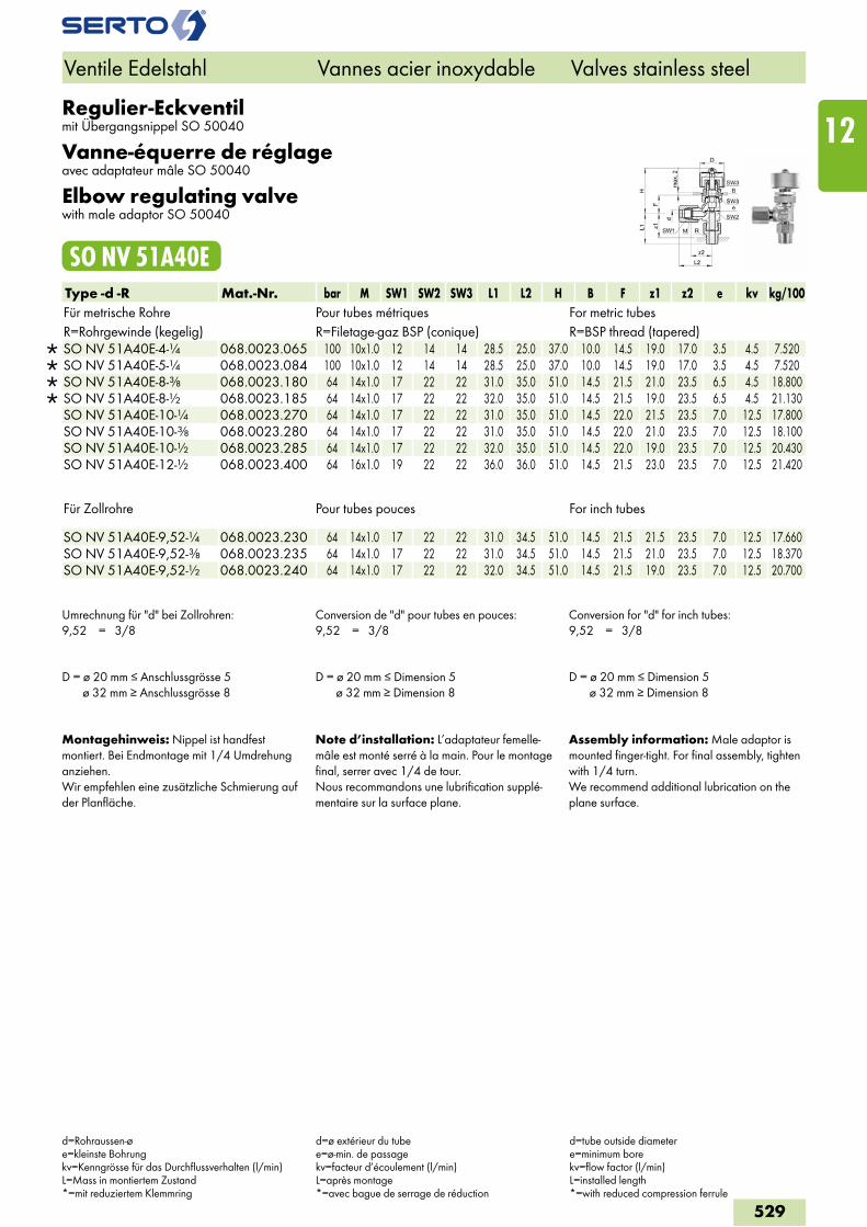
Regulier-Eckventilmit Übergangsnippel SO 50040
Vanne-équerre de réglageavec adaptateur mâle SO 50040
Elbow regulating valvewith male adaptor SO 50040
SO NV 51A40EType -d -R Mat.-Nr. bar M SW1 SW2 SW3 L1 L2 H B F z1 z2 e kv kg/100Für metrische Rohre Pour tubes métriques For metric tubesR=Rohrgewinde (kegelig) R=Filetage-gaz BSP (conique) R=BSP thread (tapered)
SO NV 51A40E-4-1/4 068.0023.065 100 10x1.0 12 14 14 28.5 25.0 37.0 10.0 14.5 19.0 17.0 3.5 4.5 7.520 SO NV 51A40E-5-1/4 068.0023.084 100 10x1.0 12 14 14 28.5 25.0 37.0 10.0 14.5 19.0 17.0 3.5 4.5 7.520 SO NV 51A40E-8-3/8 068.0023.180 64 14x1.0 17 22 22 31.0 35.0 51.0 14.5 21.5 21.0 23.5 6.5 4.5 18.800 SO NV 51A40E-8-1/2 068.0023.185 64 14x1.0 17 22 22 32.0 35.0 51.0 14.5 21.5 19.0 23.5 6.5 4.5 21.130 SO NV 51A40E-10-1/4 068.0023.270 64 14x1.0 17 22 22 31.0 35.0 51.0 14.5 22.0 21.5 23.5 7.0 12.5 17.800 SO NV 51A40E-10-3/8 068.0023.280 64 14x1.0 17 22 22 31.0 35.0 51.0 14.5 22.0 21.0 23.5 7.0 12.5 18.100 SO NV 51A40E-10-1/2 068.0023.285 64 14x1.0 17 22 22 32.0 35.0 51.0 14.5 22.0 19.0 23.5 7.0 12.5 20.430 SO NV 51A40E-12-1/2 068.0023.400 64 16x1.0 19 22 22 36.0 36.0 51.0 14.5 21.5 23.0 23.5 7.0 12.5 21.420
Für Zollrohre Pour tubes pouces For inch tubes SO NV 51A40E-9,52-1/4 068.0023.230 64 14x1.0 17 22 22 31.0 34.5 51.0 14.5 21.5 21.5 23.5 7.0 12.5 17.660SO NV 51A40E-9,52-3/8 068.0023.235 64 14x1.0 17 22 22 31.0 34.5 51.0 14.5 21.5 21.0 23.5 7.0 12.5 18.370SO NV 51A40E-9,52-1/2 068.0023.240 64 14x1.0 17 22 22 32.0 34.5 51.0 14.5 21.5 19.0 23.5 7.0 12.5 20.700
Umrechnung für "d" bei Zollrohren:9,52 = 3/8
Conversion de "d" pour tubes en pouces:9,52 = 3/8
Conversion for "d" for inch tubes:9,52 = 3/8
D = ø 20 mm ≤ Anschlussgrösse 5 ø 32 mm ≥ Anschlussgrösse 8
D = ø 20 mm ≤ Dimension 5 ø 32 mm ≥ Dimension 8
D = ø 20 mm ≤ Dimension 5 ø 32 mm ≥ Dimension 8
Montagehinweis: Nippel ist handfest montiert. Bei Endmontage mit 1/4 Umdrehung anziehen.Wir empfehlen eine zusätzliche Schmierung auf der Planfläche.
Note d’installation: L’adaptateur femelle-mâle est monté serré à la main. Pour le montage final, serrer avec 1/4 de tour.Nous recommandons une lubrification supplé-mentaire sur la surface plane.
Assembly information: Male adaptor is mounted finger-tight. For final assembly, tighten with 1/4 turn.We recommend additional lubrication on the plane surface.
Ventile Edelstahl Vannes acier inoxydable Valves stainless steel
d=Rohraussen-øe=kleinste Bohrungkv=Kenngrösse für das Durchflussverhalten (l/min)L=Mass in montiertem Zustand*=mit reduziertem Klemmring
d=ø extérieur du tubee=ø-min. de passagekv=facteur d’écoulement (l/min)L=après montage*=avec bague de serrage de réduction
d=tube outside diametere=minimum borekv=flow factor (l/min)L=installed length*=with reduced compression ferrule
529
12
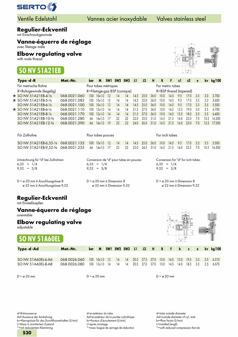
Regulier-Eckventilmit Einschraubgewinde
Vanne-équerre de réglageavec filetage mâle
Elbow regulating valvewith male thread
SO NV 51A21EBType -d -R Mat.-Nr. bar M SW1 SW2 SW3 L1 L2 H B F z1 z2 e kv kg/100Für metrische Rohre Pour tubes métriques For metric tubesR=Rohrgewinde (kegelig) R=Filetage-gaz BSP (conique) R=BSP thread (tapered)
SO NV 51A21EB-4-1/8 068.0021.060 100 10x1.0 12 14 14 14.5 25.0 36.0 10.0 14.5 9.5 17.0 3.5 3.0 5.700 SO NV 51A21EB-5-1/8 068.0021.082 100 10x1.0 12 14 14 14.5 25.0 36.0 10.0 14.5 9.5 17.0 3.5 3.2 5.600 SO NV 51A21EB-6-1/8 068.0021.100 100 10x1.0 12 14 14 14.5 25.0 36.0 10.0 14.5 9.5 17.0 3.5 3.5 5.500
SO NV 51A21EB-6-1/4 068.0021.110 100 12x1.0 14 14 14 21.5 27.0 36.0 10.0 14.5 13.5 19.0 5.0 3.5 6.700 SO NV 51A21EB-8-1/4 068.0021.170 100 12x1.0 14 14 14 21.5 27.0 36.0 10.0 14.5 13.5 18.0 3.5 3.5 6.400 SO NV 51A21EB-10-3/8 068.0021.280 64 14x1.0 17 22 22 22.0 35.0 51.0 14.5 21.5 14.0 23.0 7.0 10.5 16.300 SO NV 51A21EB-12-3/8 068.0021.390 64 16x1.0 19 22 22 24.0 36.0 51.0 14.5 21.5 16.0 23.0 7.0 12.5 17.200
Für Zollrohre Pour tubes pouces For inch tubes
SO NV 51A21EB-6,35-1/8 068.0021.135 100 10x1.0 12 14 14 14.5 25.0 36.0 10.0 14.5 9.5 17.0 3.5 3.5 5.500 SO NV 51A21EB-9,52-3/8 068.0021.235 64 14x1.0 17 22 22 22.0 34.5 51.0 14.5 21.5 14.0 23.5 7.0 10.5 16.500
Umrechnung für "d" bei Zollrohren:6,35 = 1/49,52 = 3/8
Conversion de "d" pour tubes en pouces:6,35 = 1/49,52 = 3/8
Conversion for "d" for inch tubes:6,35 = 1/49,52 = 3/8
D = ø 20 mm ≤ Anschlussgrösse 8 ø 32 mm ≥ Anschlussgrösse 9,52
D = ø 20 mm ≤ Dimension 8 ø 32 mm ≥ Dimension 9,52
D = ø 20 mm ≤ Dimension 8 ø 32 mm ≥ Dimension 9,52
Regulier-Eckventilmit Einstellzapfen
Vanne-équerre de réglageorientable
Elbow regulating valveadjustable
SO NV 51A60ELType -d -Ad Mat.-Nr. bar M SW1 SW2 SW3 L1 L2 H B F b z e kv kg/100
SO NV 51A60EL-6-A6 068.0026.060 100 10x1.0 12 14 14 20.5 27.5 37.0 10.0 14.5 13.0 19.5 3.5 3.5 6.310 SO NV 51A60EL-8-A8 068.0026.080 100 12x1.0 14 14 14 20.5 27.0 37.0 10.0 14.5 14.0 18.5 3.5 3.5 6.670
D = ø 20 mm D = ø 20 mm D = ø 20 mm
Ventile Edelstahl Vannes acier inoxydable Valves stainless steel
d=Rohraussen-øAd=Aussen-ø der Andrehungkv=Kenngrösse für das Durchflussverhalten (l/min)L=Mass in montiertem Zustand*=mit reduziertem Klemmring
d=ø extérieur du tubeAd=ø extérieur de la portée cylindriquekv=facteur d’écoulement (l/min)L=après montage*=avec bague de serrage de réduction
d=tube outside diameterAd=outside diameter of cyl. stubkv=flow factor (l/min)L=installed length*=with reduced compression ferrule
530
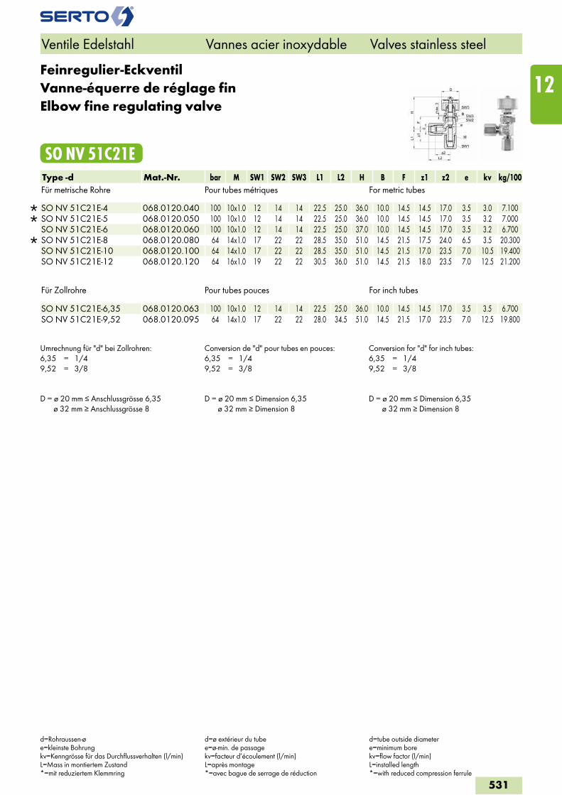
Feinregulier-EckventilVanne-équerre de réglage finElbow fine regulating valve
SO NV 51C21EType -d Mat.-Nr. bar M SW1 SW2 SW3 L1 L2 H B F z1 z2 e kv kg/100Für metrische Rohre Pour tubes métriques For metric tubes
SO NV 51C21E-4 068.0120.040 100 10x1.0 12 14 14 22.5 25.0 36.0 10.0 14.5 14.5 17.0 3.5 3.0 7.100 SO NV 51C21E-5 068.0120.050 100 10x1.0 12 14 14 22.5 25.0 36.0 10.0 14.5 14.5 17.0 3.5 3.2 7.000 SO NV 51C21E-6 068.0120.060 100 10x1.0 12 14 14 22.5 25.0 37.0 10.0 14.5 14.5 17.0 3.5 3.2 6.700
SO NV 51C21E-8 068.0120.080 64 14x1.0 17 22 22 28.5 35.0 51.0 14.5 21.5 17.5 24.0 6.5 3.5 20.300 SO NV 51C21E-10 068.0120.100 64 14x1.0 17 22 22 28.5 35.0 51.0 14.5 21.5 17.0 23.5 7.0 10.5 19.400 SO NV 51C21E-12 068.0120.120 64 16x1.0 19 22 22 30.5 36.0 51.0 14.5 21.5 18.0 23.5 7.0 12.5 21.200
Für Zollrohre Pour tubes pouces For inch tubes SO NV 51C21E-6,35 068.0120.063 100 10x1.0 12 14 14 22.5 25.0 36.0 10.0 14.5 14.5 17.0 3.5 3.5 6.700SO NV 51C21E-9,52 068.0120.095 64 14x1.0 17 22 22 28.0 34.5 51.0 14.5 21.5 17.0 23.5 7.0 12.5 19.800
Umrechnung für "d" bei Zollrohren:6,35 = 1/49,52 = 3/8
Conversion de "d" pour tubes en pouces:6,35 = 1/49,52 = 3/8
Conversion for "d" for inch tubes:6,35 = 1/49,52 = 3/8
D = ø 20 mm ≤ Anschlussgrösse 6,35 ø 32 mm ≥ Anschlussgrösse 8
D = ø 20 mm ≤ Dimension 6,35 ø 32 mm ≥ Dimension 8
D = ø 20 mm ≤ Dimension 6,35 ø 32 mm ≥ Dimension 8
Ventile Edelstahl Vannes acier inoxydable Valves stainless steel
d=Rohraussen-øe=kleinste Bohrungkv=Kenngrösse für das Durchflussverhalten (l/min)L=Mass in montiertem Zustand*=mit reduziertem Klemmring
d=ø extérieur du tubee=ø-min. de passagekv=facteur d’écoulement (l/min)L=après montage*=avec bague de serrage de réduction
d=tube outside diametere=minimum borekv=flow factor (l/min)L=installed length*=with reduced compression ferrule
531
12
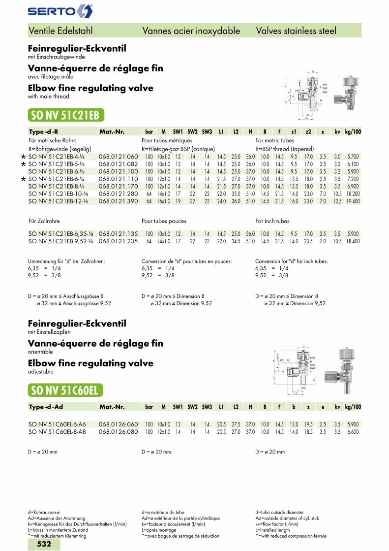
Feinregulier-Eckventilmit Einschraubgewinde
Vanne-équerre de réglage finavec filetage mâle
Elbow fine regulating valvewith male thread
SO NV 51C21EBType -d -R Mat.-Nr. bar M SW1 SW2 SW3 L1 L2 H B F z1 z2 e kv kg/100Für metrische Rohre Pour tubes métriques For metric tubesR=Rohrgewinde (kegelig) R=Filetage-gaz BSP (conique) R=BSP thread (tapered)
SO NV 51C21EB-4-1/8 068.0121.060 100 10x1.0 12 14 14 14.5 25.0 36.0 10.0 14.5 9.5 17.0 3.5 3.0 5.700 SO NV 51C21EB-5-1/8 068.0121.082 100 10x1.0 12 14 14 14.5 25.0 36.0 10.0 14.5 9.5 17.0 3.5 3.2 6.100 SO NV 51C21EB-6-1/8 068.0121.100 100 10x1.0 12 14 14 14.5 25.0 37.0 10.0 14.5 9.5 17.0 3.5 3.2 5.900
SO NV 51C21EB-6-1/4 068.0121.110 100 12x1.0 14 14 14 21.5 27.0 37.0 10.0 14.5 13.5 18.0 3.5 3.5 7.200 SO NV 51C21EB-8-1/4 068.0121.170 100 12x1.0 14 14 14 21.5 27.0 37.0 10.0 14.5 13.5 18.0 3.5 3.5 6.900 SO NV 51C21EB-10-3/8 068.0121.280 64 14x1.0 17 22 22 22.0 35.0 51.0 14.5 21.5 14.0 23.0 7.0 10.5 18.200 SO NV 51C21EB-12-3/8 068.0121.390 64 16x1.0 19 22 22 24.0 36.0 51.0 14.5 21.5 16.0 23.0 7.0 12.5 19.400
Für Zollrohre Pour tubes pouces For inch tubes SO NV 51C21EB-6,35-1/8 068.0121.135 100 10x1.0 12 14 14 14.5 25.0 36.0 10.0 14.5 9.5 17.0 3.5 3.5 5.900SO NV 51C21EB-9,52-3/8 068.0121.235 64 14x1.0 17 22 22 22.0 34.5 51.0 14.5 21.5 14.0 23.5 7.0 10.5 18.400
Umrechnung für "d" bei Zollrohren:6,35 = 1/49,52 = 3/8
Conversion de "d" pour tubes en pouces:6,35 = 1/49,52 = 3/8
Conversion for "d" for inch tubes:6,35 = 1/49,52 = 3/8
D = ø 20 mm ≤ Anschlussgrösse 8 ø 32 mm ≥ Anschlussgrösse 9,52
D = ø 20 mm ≤ Dimension 8 ø 32 mm ≥ Dimension 9,52
D = ø 20 mm ≤ Dimension 8 ø 32 mm ≥ Dimension 9,52
Feinregulier-Eckventilmit Einstellzapfen
Vanne-équerre de réglage finorientable
Elbow fine regulating valveadjustable
SO NV 51C60ELType -d -Ad Mat.-Nr. bar M SW1 SW2 SW3 L1 L2 H B F b z e kv kg/100 SO NV 51C60EL-6-A6 068.0126.060 100 10x1.0 12 14 14 20.5 27.5 37.0 10.0 14.5 13.0 19.5 3.5 3.5 5.900SO NV 51C60EL-8-A8 068.0126.080 100 12x1.0 14 14 14 20.5 27.0 37.0 10.0 14.5 14.0 18.5 3.5 3.5 6.600
D = ø 20 mm D = ø 20 mm D = ø 20 mm
Ventile Edelstahl Vannes acier inoxydable Valves stainless steel
d=Rohraussen-øAd=Aussen-ø der Andrehungkv=Kenngrösse für das Durchflussverhalten (l/min)L=Mass in montiertem Zustand*=mit reduziertem Klemmring
d=ø extérieur du tubeAd=ø extérieur de la portée cylindriquekv=facteur d’écoulement (l/min)L=après montage*=avec bague de serrage de réduction
d=tube outside diameterAd=outside diameter of cyl. stubkv=flow factor (l/min)L=installed length*=with reduced compression ferrule
532
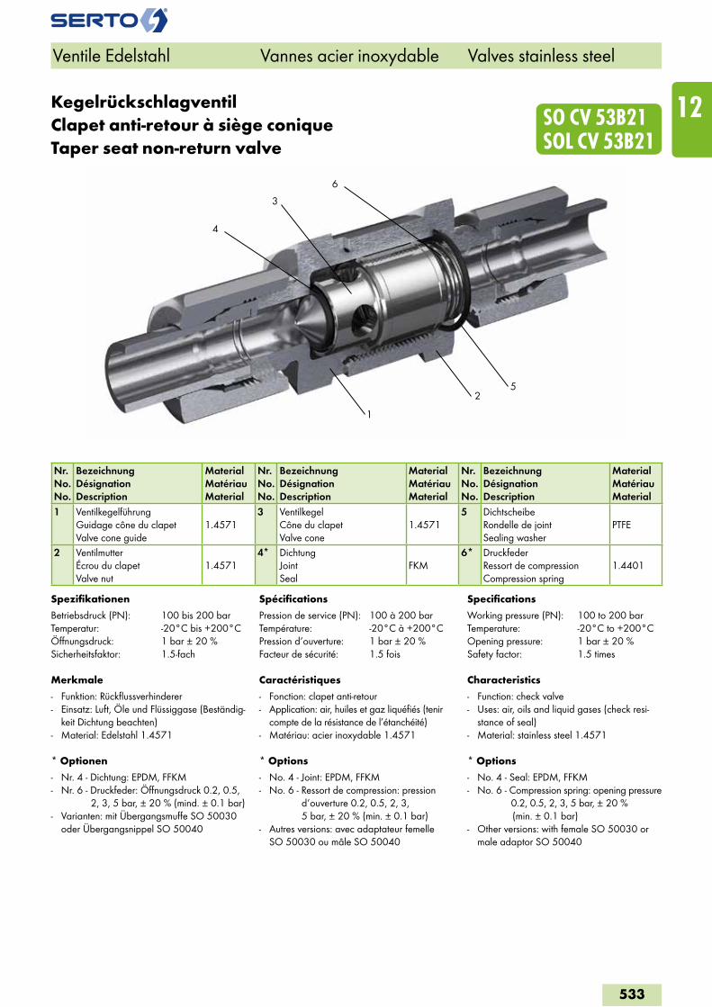
3
52
4
6
1
SO CV 53B21 SOL CV 53B21
KegelrückschlagventilClapet anti-retour à siège coniqueTaper seat non-return valve
Nr.No.No.
BezeichnungDésignationDescription
MaterialMatériauMaterial
Nr.No.No.
BezeichnungDésignationDescription
MaterialMatériauMaterial
Nr.No.No.
BezeichnungDésignationDescription
MaterialMatériauMaterial
1 VentilkegelführungGuidage cône du clapetValve cone guide
1.45713 Ventilkegel
Cône du clapetValve cone
1.45715 Dichtscheibe
Rondelle de jointSealing washer
PTFE
2 VentilmutterÉcrou du clapetValve nut
1.45714* Dichtung
JointSeal
FKM6* Druckfeder
Ressort de compressionCompression spring
1.4401
Spezifikationen
Betriebsdruck (PN): 100 bis 200 barTemperatur: -20°C bis +200°CÖffnungsdruck: 1 bar ± 20 %Sicherheitsfaktor: 1.5-fach
Merkmale
- Funktion: Rückflussverhinderer- Einsatz: Luft, Öle und Flüssiggase (Beständig-
keit Dichtung beachten)- Material: Edelstahl 1.4571
* Optionen
- Nr. 4 - Dichtung: EPDM, FFKM- Nr. 6 - Druckfeder: Öffnungsdruck 0.2, 0.5,
2, 3, 5 bar, ± 20 % (mind. ± 0.1 bar)- Varianten: mit Übergangsmuffe SO 50030
oder Übergangsnippel SO 50040
Spécifications
Pression de service (PN): 100 à 200 barTempérature: -20°C à +200°CPression d‘ouverture: 1 bar ± 20 %Facteur de sécurité: 1.5 fois
Caractéristiques
- Fonction: clapet anti-retour- Application: air, huiles et gaz liquéfiés (tenir
compte de la résistance de l’étanchéité)- Matériau: acier inoxydable 1.4571
* Options
- No. 4 - Joint: EPDM, FFKM- No. 6 - Ressort de compression: pression
d‘ouverture 0.2, 0.5, 2, 3, 5 bar, ± 20 % (min. ± 0.1 bar)
- Autres versions: avec adaptateur femelle SO 50030 ou mâle SO 50040
Specifications
Working pressure (PN): 100 to 200 barTemperature: -20°C to +200°COpening pressure: 1 bar ± 20 %Safety factor: 1.5 times
Characteristics
- Function: check valve- Uses: air, oils and liquid gases (check resi-
stance of seal) - Material: stainless steel 1.4571
* Options
- No. 4 - Seal: EPDM, FFKM- No. 6 - Compression spring: opening pressure
0.2, 0.5, 2, 3, 5 bar, ± 20 % (min. ± 0.1 bar)
- Other versions: with female SO 50030 or male adaptor SO 50040
Ventile Edelstahl Vannes acier inoxydable Valves stainless steel
533
12
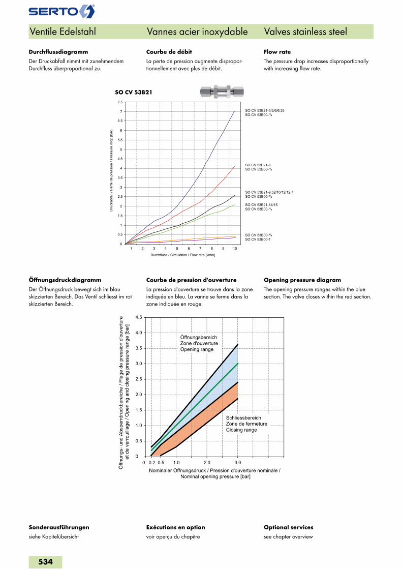
SO CV 53B21
Ventile Edelstahl Vannes acier inoxydable Valves stainless steel
Exécutions en option
voir aperçu du chapitre
Optional services
see chapter overview
Sonderausführungen
siehe Kapitelübersicht
Durchfluss / Circulation / Flow rate [l/min]
Dru
ckab
fall
/ Per
te d
e pr
essi
on /
Pres
sure
dro
p [b
ar]
SO CV 53B21-4/5/6/6,35SO CV 53B00-¹/�
SO CV 53B21-8SO CV 53B00-¹/�
SO CV 53B21-9,52/10/12/12,7SO CV 53B00-³/�
SO CV 53B21-14/15SO CV 53B00-¹/�
0
0.5
1
1.5
2
2.5
3
3.5
4
4.5
5
5.5
6
6.5
7
7.5
1 2 3 4 5 6 7 8 9 10
SO CV 53B00-³/� SO CV 53B00-1
Courbe de débit
La perte de pression augmente dispropor-tionnellement avec plus de débit.
Flow rate
The pressure drop increases disproportionally with increasing flow rate.
Durchflussdiagramm
Der Druckabfall nimmt mit zunehmendem Durchfluss überproportional zu.
Courbe de pression d'ouverture
La pression d'ouverture se trouve dans la zone indiquée en bleu. La vanne se ferme dans la zone indiquée en rouge.
Opening pressure diagram
The opening pressure ranges within the blue section. The valve closes within the red section.
Öffnungsdruckdiagramm
Der Öffnungsdruck bewegt sich im blau skizzierten Bereich. Das Ventil schliesst im rot skizzierten Bereich.
0
0.5
1.0
1.5
2.0
2.5
3.0
3.5
4.0
4.5
0 0.50.2 1.0 2.0 3.0
Öffn
ungs
- und
Abs
perrd
ruck
bere
iche
/ Pl
age
de p
ress
ion
d'ou
vertu
re
et d
e ve
rroui
llage
/ O
peni
ng a
nd c
losi
ng p
ress
ure
rang
e [b
ar]
Nominaler Öffnungsdruck / Pression d'ouverture nominale / Nominal opening pressure [bar]
ÖffnungsbereichZone d'ouvertureOpening range
SchliessbereichZone de fermetureClosing range
534
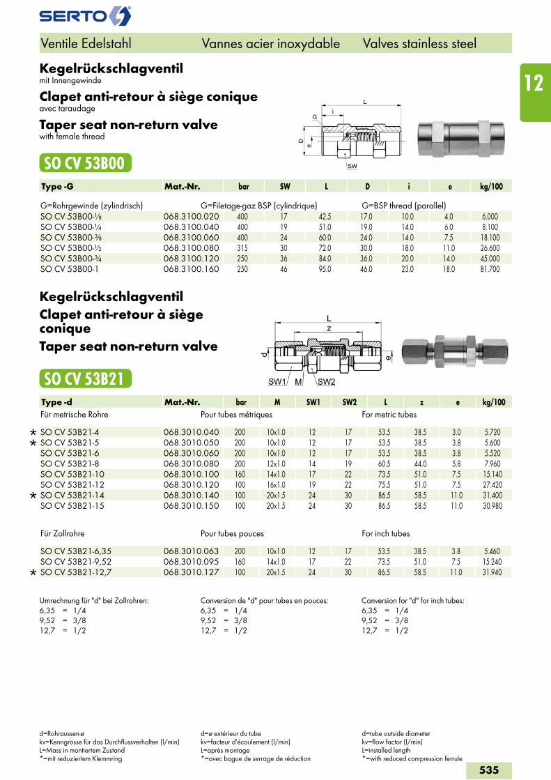
Kegelrückschlagventilmit Innengewinde
Clapet anti-retour à siège coniqueavec taraudage
Taper seat non-return valvewith female thread
SO CV 53B00Type -G Mat.-Nr. bar SW L D i e kg/100 G=Rohrgewinde (zylindrisch) G=Filetage-gaz BSP (cylindrique) G=BSP thread (parallel)SO CV 53B00-1/8 068.3100.020 400 17 42.5 17.0 10.0 4.0 6.000SO CV 53B00-1/4 068.3100.040 400 19 51.0 19.0 14.0 6.0 8.100SO CV 53B00-3/8 068.3100.060 400 24 60.0 24.0 14.0 7.5 18.100SO CV 53B00-1/2 068.3100.080 315 30 72.0 30.0 18.0 11.0 26.600SO CV 53B00-3/4 068.3100.120 250 36 84.0 36.0 20.0 14.0 45.000SO CV 53B00-1 068.3100.160 250 46 95.0 46.0 23.0 18.0 81.700
KegelrückschlagventilClapet anti-retour à siège coniqueTaper seat non-return valve
SO CV 53B21Type -d Mat.-Nr. bar M SW1 SW2 L z e kg/100Für metrische Rohre Pour tubes métriques For metric tubes
SO CV 53B21-4 068.3010.040 200 10x1.0 12 17 53.5 38.5 3.0 5.720 SO CV 53B21-5 068.3010.050 200 10x1.0 12 17 53.5 38.5 3.8 5.600 SO CV 53B21-6 068.3010.060 200 10x1.0 12 17 53.5 38.5 3.8 5.520 SO CV 53B21-8 068.3010.080 200 12x1.0 14 19 60.5 44.0 5.8 7.960 SO CV 53B21-10 068.3010.100 160 14x1.0 17 22 73.5 51.0 7.5 15.140 SO CV 53B21-12 068.3010.120 100 16x1.0 19 22 75.5 51.0 7.5 27.420
SO CV 53B21-14 068.3010.140 100 20x1.5 24 30 86.5 58.5 11.0 31.400 SO CV 53B21-15 068.3010.150 100 20x1.5 24 30 86.5 58.5 11.0 30.980
Für Zollrohre Pour tubes pouces For inch tubes
SO CV 53B21-6,35 068.3010.063 200 10x1.0 12 17 53.5 38.5 3.8 5.460 SO CV 53B21-9,52 068.3010.095 160 14x1.0 17 22 73.5 51.0 7.5 15.240
SO CV 53B21-12,7 068.3010.127 100 20x1.5 24 30 86.5 58.5 11.0 31.940
Umrechnung für "d" bei Zollrohren:6,35 = 1/49,52 = 3/812,7 = 1/2
Conversion de "d" pour tubes en pouces:6,35 = 1/49,52 = 3/812,7 = 1/2
Conversion for "d" for inch tubes:6,35 = 1/49,52 = 3/812,7 = 1/2
Ventile Edelstahl Vannes acier inoxydable Valves stainless steel
d=Rohraussen-økv=Kenngrösse für das Durchflussverhalten (l/min)L=Mass in montiertem Zustand*=mit reduziertem Klemmring
d=ø extérieur du tubekv=facteur d’écoulement (l/min)L=après montage*=avec bague de serrage de réduction
d=tube outside diameterkv=flow factor (l/min)L=installed length*=with reduced compression ferrule
535
12
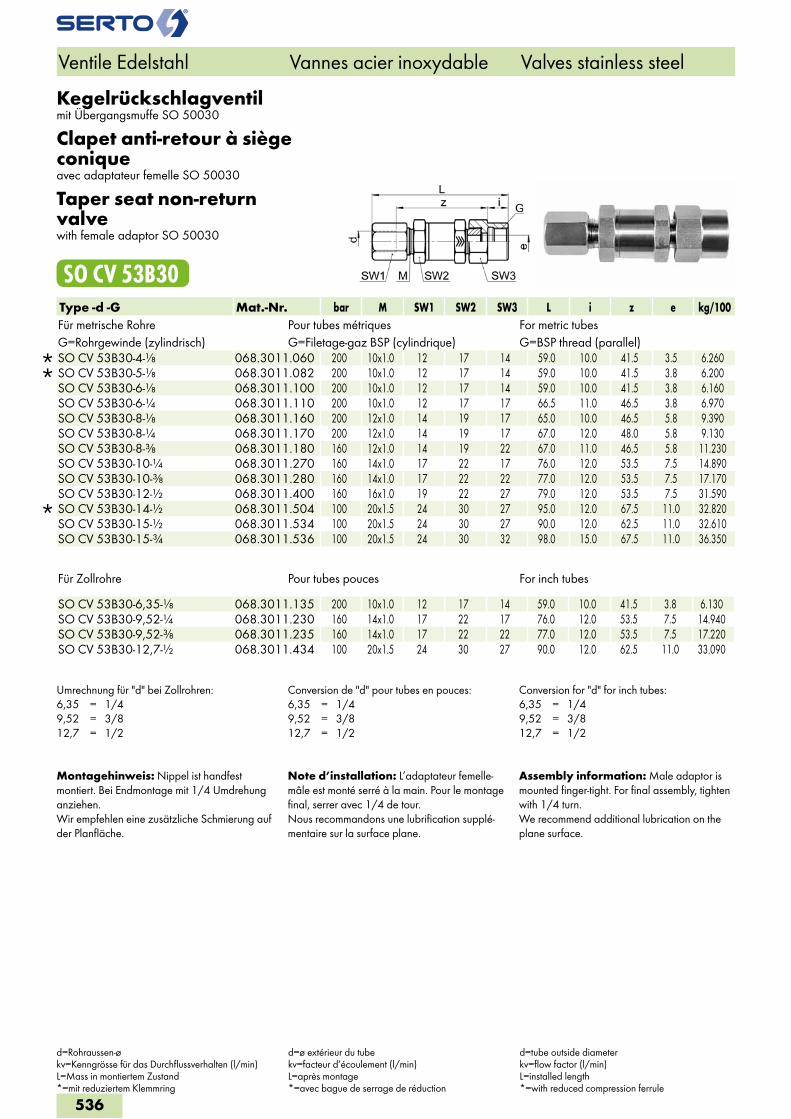
Kegelrückschlagventilmit Übergangsmuffe SO 50030
Clapet anti-retour à siège coniqueavec adaptateur femelle SO 50030
Taper seat non-return valvewith female adaptor SO 50030
SO CV 53B30Type -d -G Mat.-Nr. bar M SW1 SW2 SW3 L i z e kg/100Für metrische Rohre Pour tubes métriques For metric tubesG=Rohrgewinde (zylindrisch) G=Filetage-gaz BSP (cylindrique) G=BSP thread (parallel)
SO CV 53B30-4-1/8 068.3011.060 200 10x1.0 12 17 14 59.0 10.0 41.5 3.5 6.260 SO CV 53B30-5-1/8 068.3011.082 200 10x1.0 12 17 14 59.0 10.0 41.5 3.8 6.200 SO CV 53B30-6-1/8 068.3011.100 200 10x1.0 12 17 14 59.0 10.0 41.5 3.8 6.160 SO CV 53B30-6-1/4 068.3011.110 200 10x1.0 12 17 17 66.5 11.0 46.5 3.8 6.970 SO CV 53B30-8-1/8 068.3011.160 200 12x1.0 14 19 17 65.0 10.0 46.5 5.8 9.390 SO CV 53B30-8-1/4 068.3011.170 200 12x1.0 14 19 17 67.0 12.0 48.0 5.8 9.130 SO CV 53B30-8-3/8 068.3011.180 160 12x1.0 14 19 22 67.0 11.0 46.5 5.8 11.230 SO CV 53B30-10-1/4 068.3011.270 160 14x1.0 17 22 17 76.0 12.0 53.5 7.5 14.890 SO CV 53B30-10-3/8 068.3011.280 160 14x1.0 17 22 22 77.0 12.0 53.5 7.5 17.170 SO CV 53B30-12-1/2 068.3011.400 160 16x1.0 19 22 27 79.0 12.0 53.5 7.5 31.590
SO CV 53B30-14-1/2 068.3011.504 100 20x1.5 24 30 27 95.0 12.0 67.5 11.0 32.820 SO CV 53B30-15-1/2 068.3011.534 100 20x1.5 24 30 27 90.0 12.0 62.5 11.0 32.610 SO CV 53B30-15-3/4 068.3011.536 100 20x1.5 24 30 32 98.0 15.0 67.5 11.0 36.350
Für Zollrohre Pour tubes pouces For inch tubes
SO CV 53B30-6,35-1/8 068.3011.135 200 10x1.0 12 17 14 59.0 10.0 41.5 3.8 6.130 SO CV 53B30-9,52-1/4 068.3011.230 160 14x1.0 17 22 17 76.0 12.0 53.5 7.5 14.940 SO CV 53B30-9,52-3/8 068.3011.235 160 14x1.0 17 22 22 77.0 12.0 53.5 7.5 17.220 SO CV 53B30-12,7-1/2 068.3011.434 100 20x1.5 24 30 27 90.0 12.0 62.5 11.0 33.090
Umrechnung für "d" bei Zollrohren:6,35 = 1/49,52 = 3/812,7 = 1/2
Conversion de "d" pour tubes en pouces:6,35 = 1/49,52 = 3/812,7 = 1/2
Conversion for "d" for inch tubes:6,35 = 1/49,52 = 3/812,7 = 1/2
Montagehinweis: Nippel ist handfest montiert. Bei Endmontage mit 1/4 Umdrehung anziehen.Wir empfehlen eine zusätzliche Schmierung auf der Planfläche.
Note d’installation: L’adaptateur femelle-mâle est monté serré à la main. Pour le montage final, serrer avec 1/4 de tour.Nous recommandons une lubrification supplé-mentaire sur la surface plane.
Assembly information: Male adaptor is mounted finger-tight. For final assembly, tighten with 1/4 turn.We recommend additional lubrication on the plane surface.
Ventile Edelstahl Vannes acier inoxydable Valves stainless steel
d=Rohraussen-økv=Kenngrösse für das Durchflussverhalten (l/min)L=Mass in montiertem Zustand*=mit reduziertem Klemmring
d=ø extérieur du tubekv=facteur d’écoulement (l/min)L=après montage*=avec bague de serrage de réduction
d=tube outside diameterkv=flow factor (l/min)L=installed length*=with reduced compression ferrule
536
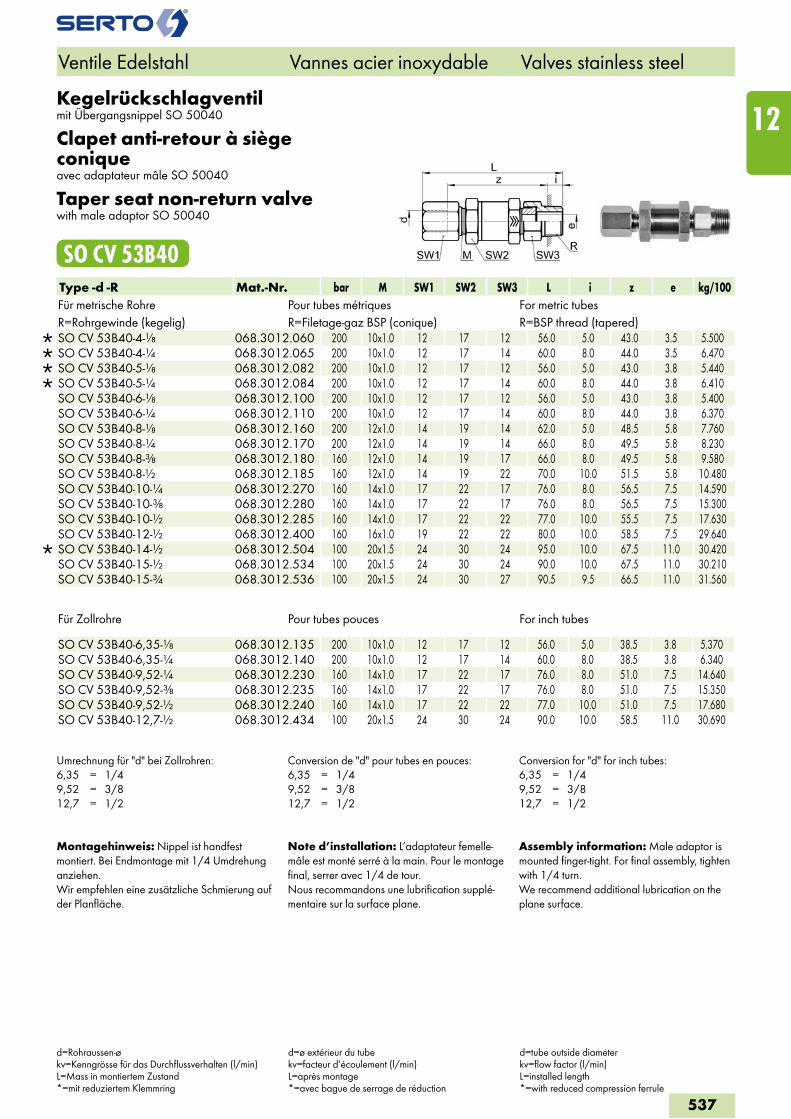
Kegelrückschlagventilmit Übergangsnippel SO 50040
Clapet anti-retour à siège coniqueavec adaptateur mâle SO 50040
Taper seat non-return valvewith male adaptor SO 50040
SO CV 53B40Type -d -R Mat.-Nr. bar M SW1 SW2 SW3 L i z e kg/100Für metrische Rohre Pour tubes métriques For metric tubesR=Rohrgewinde (kegelig) R=Filetage-gaz BSP (conique) R=BSP thread (tapered)
SO CV 53B40-4-1/8 068.3012.060 200 10x1.0 12 17 12 56.0 5.0 43.0 3.5 5.500 SO CV 53B40-4-1/4 068.3012.065 200 10x1.0 12 17 14 60.0 8.0 44.0 3.5 6.470 SO CV 53B40-5-1/8 068.3012.082 200 10x1.0 12 17 12 56.0 5.0 43.0 3.8 5.440 SO CV 53B40-5-1/4 068.3012.084 200 10x1.0 12 17 14 60.0 8.0 44.0 3.8 6.410 SO CV 53B40-6-1/8 068.3012.100 200 10x1.0 12 17 12 56.0 5.0 43.0 3.8 5.400 SO CV 53B40-6-1/4 068.3012.110 200 10x1.0 12 17 14 60.0 8.0 44.0 3.8 6.370 SO CV 53B40-8-1/8 068.3012.160 200 12x1.0 14 19 14 62.0 5.0 48.5 5.8 7.760 SO CV 53B40-8-1/4 068.3012.170 200 12x1.0 14 19 14 66.0 8.0 49.5 5.8 8.230 SO CV 53B40-8-3/8 068.3012.180 160 12x1.0 14 19 17 66.0 8.0 49.5 5.8 9.580 SO CV 53B40-8-1/2 068.3012.185 160 12x1.0 14 19 22 70.0 10.0 51.5 5.8 10.480 SO CV 53B40-10-1/4 068.3012.270 160 14x1.0 17 22 17 76.0 8.0 56.5 7.5 14.590 SO CV 53B40-10-3/8 068.3012.280 160 14x1.0 17 22 17 76.0 8.0 56.5 7.5 15.300 SO CV 53B40-10-1/2 068.3012.285 160 14x1.0 17 22 22 77.0 10.0 55.5 7.5 17.630 SO CV 53B40-12-1/2 068.3012.400 160 16x1.0 19 22 22 80.0 10.0 58.5 7.5 29.640
SO CV 53B40-14-1/2 068.3012.504 100 20x1.5 24 30 24 95.0 10.0 67.5 11.0 30.420 SO CV 53B40-15-1/2 068.3012.534 100 20x1.5 24 30 24 90.0 10.0 67.5 11.0 30.210 SO CV 53B40-15-3/4 068.3012.536 100 20x1.5 24 30 27 90.5 9.5 66.5 11.0 31.560
Für Zollrohre Pour tubes pouces For inch tubes
SO CV 53B40-6,35-1/8 068.3012.135 200 10x1.0 12 17 12 56.0 5.0 38.5 3.8 5.370 SO CV 53B40-6,35-1/4 068.3012.140 200 10x1.0 12 17 14 60.0 8.0 38.5 3.8 6.340 SO CV 53B40-9,52-1/4 068.3012.230 160 14x1.0 17 22 17 76.0 8.0 51.0 7.5 14.640 SO CV 53B40-9,52-3/8 068.3012.235 160 14x1.0 17 22 17 76.0 8.0 51.0 7.5 15.350 SO CV 53B40-9,52-1/2 068.3012.240 160 14x1.0 17 22 22 77.0 10.0 51.0 7.5 17.680 SO CV 53B40-12,7-1/2 068.3012.434 100 20x1.5 24 30 24 90.0 10.0 58.5 11.0 30.690
Umrechnung für "d" bei Zollrohren:6,35 = 1/49,52 = 3/812,7 = 1/2
Conversion de "d" pour tubes en pouces:6,35 = 1/49,52 = 3/812,7 = 1/2
Conversion for "d" for inch tubes:6,35 = 1/49,52 = 3/812,7 = 1/2
Montagehinweis: Nippel ist handfest montiert. Bei Endmontage mit 1/4 Umdrehung anziehen.Wir empfehlen eine zusätzliche Schmierung auf der Planfläche.
Note d’installation: L’adaptateur femelle-mâle est monté serré à la main. Pour le montage final, serrer avec 1/4 de tour.Nous recommandons une lubrification supplé-mentaire sur la surface plane.
Assembly information: Male adaptor is mounted finger-tight. For final assembly, tighten with 1/4 turn.We recommend additional lubrication on the plane surface.
Ventile Edelstahl Vannes acier inoxydable Valves stainless steel
d=Rohraussen-økv=Kenngrösse für das Durchflussverhalten (l/min)L=Mass in montiertem Zustand*=mit reduziertem Klemmring
d=ø extérieur du tubekv=facteur d’écoulement (l/min)L=après montage*=avec bague de serrage de réduction
d=tube outside diameterkv=flow factor (l/min)L=installed length*=with reduced compression ferrule
537
12
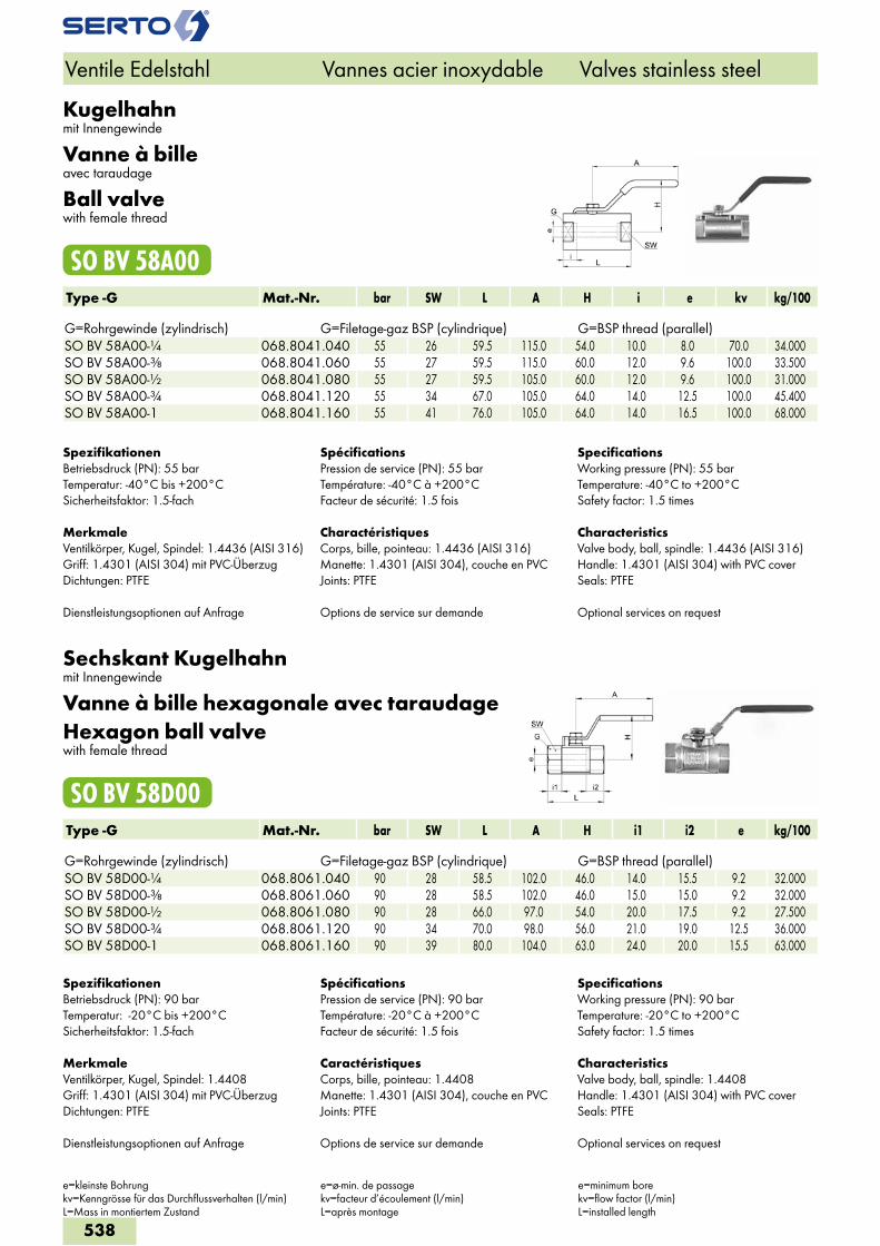
Kugelhahnmit Innengewinde
Vanne à billeavec taraudage
Ball valvewith female thread
SO BV 58A00Type -G Mat.-Nr. bar SW L A H i e kv kg/100 G=Rohrgewinde (zylindrisch) G=Filetage-gaz BSP (cylindrique) G=BSP thread (parallel)SO BV 58A00-1/4 068.8041.040 55 26 59.5 115.0 54.0 10.0 8.0 70.0 34.000SO BV 58A00-3/8 068.8041.060 55 27 59.5 115.0 60.0 12.0 9.6 100.0 33.500SO BV 58A00-1/2 068.8041.080 55 27 59.5 105.0 60.0 12.0 9.6 100.0 31.000SO BV 58A00-3/4 068.8041.120 55 34 67.0 105.0 64.0 14.0 12.5 100.0 45.400SO BV 58A00-1 068.8041.160 55 41 76.0 105.0 64.0 14.0 16.5 100.0 68.000
SpezifikationenBetriebsdruck (PN): 55 barTemperatur: -40°C bis +200°CSicherheitsfaktor: 1.5-fach
MerkmaleVentilkörper, Kugel, Spindel: 1.4436 (AISI 316)Griff: 1.4301 (AISI 304) mit PVC-ÜberzugDichtungen: PTFE
Dienstleistungsoptionen auf Anfrage
SpécificationsPression de service (PN): 55 barTempérature: -40°C à +200°CFacteur de sécurité: 1.5 fois
CharactéristiquesCorps, bille, pointeau: 1.4436 (AISI 316)Manette: 1.4301 (AISI 304), couche en PVCJoints: PTFE
Options de service sur demande
SpecificationsWorking pressure (PN): 55 barTemperature: -40°C to +200°CSafety factor: 1.5 times
CharacteristicsValve body, ball, spindle: 1.4436 (AISI 316)Handle: 1.4301 (AISI 304) with PVC coverSeals: PTFE
Optional services on request
Sechskant Kugelhahnmit Innengewinde
Vanne à bille hexagonale avec taraudageHexagon ball valvewith female thread
SO BV 58D00Type -G Mat.-Nr. bar SW L A H i1 i2 e kg/100 G=Rohrgewinde (zylindrisch) G=Filetage-gaz BSP (cylindrique) G=BSP thread (parallel)SO BV 58D00-1/4 068.8061.040 90 28 58.5 102.0 46.0 14.0 15.5 9.2 32.000SO BV 58D00-3/8 068.8061.060 90 28 58.5 102.0 46.0 15.0 15.0 9.2 32.000SO BV 58D00-1/2 068.8061.080 90 28 66.0 97.0 54.0 20.0 17.5 9.2 27.500SO BV 58D00-3/4 068.8061.120 90 34 70.0 98.0 56.0 21.0 19.0 12.5 36.000SO BV 58D00-1 068.8061.160 90 39 80.0 104.0 63.0 24.0 20.0 15.5 63.000
Ventile Edelstahl Vannes acier inoxydable Valves stainless steel
e=kleinste Bohrungkv=Kenngrösse für das Durchflussverhalten (l/min)L=Mass in montiertem Zustand
e=ø-min. de passagekv=facteur d’écoulement (l/min)L=après montage
e=minimum borekv=flow factor (l/min)L=installed length
SpezifikationenBetriebsdruck (PN): 90 barTemperatur: -20°C bis +200°CSicherheitsfaktor: 1.5-fach
MerkmaleVentilkörper, Kugel, Spindel: 1.4408Griff: 1.4301 (AISI 304) mit PVC-ÜberzugDichtungen: PTFE
Dienstleistungsoptionen auf Anfrage
SpécificationsPression de service (PN): 90 barTempérature: -20°C à +200°CFacteur de sécurité: 1.5 fois
CaractéristiquesCorps, bille, pointeau: 1.4408Manette: 1.4301 (AISI 304), couche en PVCJoints: PTFE
Options de service sur demande
SpecificationsWorking pressure (PN): 90 barTemperature: -20°C to +200°CSafety factor: 1.5 times
CharacteristicsValve body, ball, spindle: 1.4408Handle: 1.4301 (AISI 304) with PVC coverSeals: PTFE
Optional services on request
538
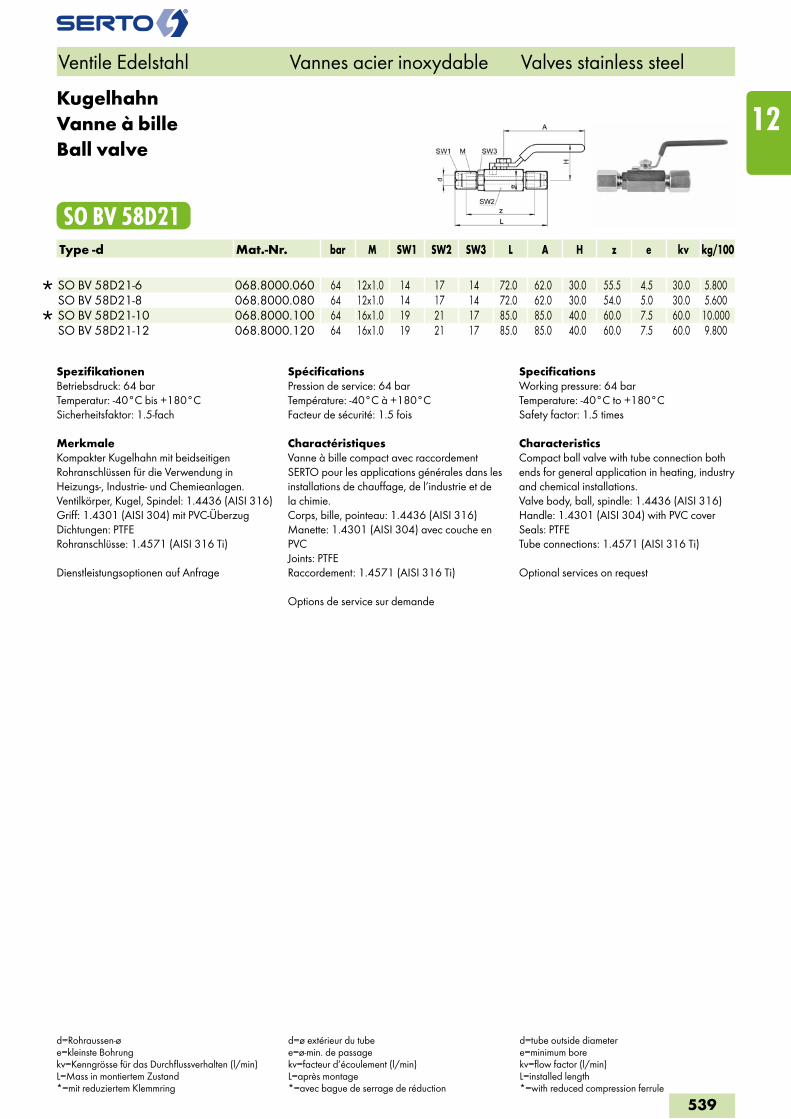
KugelhahnVanne à billeBall valve
SO BV 58D21Type -d Mat.-Nr. bar M SW1 SW2 SW3 L A H z e kv kg/100
SO BV 58D21-6 068.8000.060 64 12x1.0 14 17 14 72.0 62.0 30.0 55.5 4.5 30.0 5.800 SO BV 58D21-8 068.8000.080 64 12x1.0 14 17 14 72.0 62.0 30.0 54.0 5.0 30.0 5.600
SO BV 58D21-10 068.8000.100 64 16x1.0 19 21 17 85.0 85.0 40.0 60.0 7.5 60.0 10.000 SO BV 58D21-12 068.8000.120 64 16x1.0 19 21 17 85.0 85.0 40.0 60.0 7.5 60.0 9.800
SpezifikationenBetriebsdruck: 64 barTemperatur: -40°C bis +180°CSicherheitsfaktor: 1.5-fach
MerkmaleKompakter Kugelhahn mit beidseitigen Rohranschlüssen für die Verwendung in Heizungs-, Industrie- und Chemieanlagen.Ventilkörper, Kugel, Spindel: 1.4436 (AISI 316)Griff: 1.4301 (AISI 304) mit PVC-ÜberzugDichtungen: PTFERohranschlüsse: 1.4571 (AISI 316 Ti)
Dienstleistungsoptionen auf Anfrage
SpécificationsPression de service: 64 barTempérature: -40°C à +180°CFacteur de sécurité: 1.5 fois
CharactéristiquesVanne à bille compact avec raccordement SERTO pour les applications générales dans les installations de chauffage, de l’industrie et de la chimie.Corps, bille, pointeau: 1.4436 (AISI 316)Manette: 1.4301 (AISI 304) avec couche en PVCJoints: PTFERaccordement: 1.4571 (AISI 316 Ti)
Options de service sur demande
SpecificationsWorking pressure: 64 barTemperature: -40°C to +180°CSafety factor: 1.5 times
CharacteristicsCompact ball valve with tube connection both ends for general application in heating, industry and chemical installations.Valve body, ball, spindle: 1.4436 (AISI 316)Handle: 1.4301 (AISI 304) with PVC coverSeals: PTFETube connections: 1.4571 (AISI 316 Ti)
Optional services on request
Ventile Edelstahl Vannes acier inoxydable Valves stainless steel
d=Rohraussen-øe=kleinste Bohrungkv=Kenngrösse für das Durchflussverhalten (l/min)L=Mass in montiertem Zustand*=mit reduziertem Klemmring
d=ø extérieur du tubee=ø-min. de passagekv=facteur d’écoulement (l/min)L=après montage*=avec bague de serrage de réduction
d=tube outside diametere=minimum borekv=flow factor (l/min)L=installed length*=with reduced compression ferrule
539
12
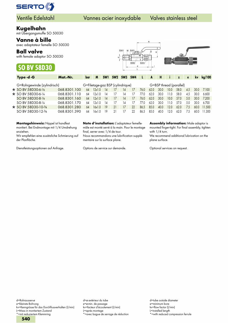
Kugelhahnmit Übergangsmuffe SO 50030
Vanne à billeavec adaptateur femelle SO 50030
Ball valvewith female adaptor SO 50030
SO BV 58D30Type -d -G Mat.-Nr. bar M SW1 SW2 SW3 SW4 L A H i z e kv kg/100 G=Rohrgewinde (zylindrisch) G=Filetage-gaz BSP (cylindrique) G=BSP thread (parallel)
SO BV 58D30-6-1/8 068.8301.100 64 12x1.0 14 17 14 17 76.0 62.0 30.0 10.0 58.0 4.5 30.0 7.100 SO BV 58D30-6-1/4 068.8301.110 64 12x1.0 14 17 14 17 77.0 62.0 30.0 11.0 58.0 4.5 30.0 6.600 SO BV 58D30-8-1/8 068.8301.160 64 12x1.0 14 17 14 17 76.0 62.0 30.0 10.0 57.0 5.0 30.0 7.200 SO BV 58D30-8-1/4 068.8301.170 64 12x1.0 14 17 14 17 77.0 62.0 30.0 11.0 57.0 5.0 30.0 6.700
SO BV 58D30-10-3/8 068.8301.280 64 16x1.0 19 21 17 22 86.5 85.0 40.0 12.0 62.0 7.5 60.0 11.500 SO BV 58D30-12-3/8 068.8301.390 64 16x1.0 19 21 17 22 86.5 85.0 40.0 12.0 62.0 7.5 60.0 11.300
Montagehinweis: Nippel ist handfest montiert. Bei Endmontage mit 1/4 Umdrehung anziehen.Wir empfehlen eine zusätzliche Schmierung auf der Planfläche.
Dienstleistungsoptionen auf Anfrage.
Note d’installation: L’adaptateur femelle-mâle est monté serré à la main. Pour le montage final, serrer avec 1/4 de tour.Nous recommandons une lubrification supplé-mentaire sur la surface plane.
Options de service sur demande.
Assembly information: Male adaptor is mounted finger-tight. For final assembly, tighten with 1/4 turn.We recommend additional lubrication on the plane surface.
Optional services on request.
Ventile Edelstahl Vannes acier inoxydable Valves stainless steel
d=Rohraussen-øe=kleinste Bohrungkv=Kenngrösse für das Durchflussverhalten (l/min)L=Mass in montiertem Zustand*=mit reduziertem Klemmring
d=ø extérieur du tubee=ø-min. de passagekv=facteur d’écoulement (l/min)L=après montage*=avec bague de serrage de réduction
d=tube outside diametere=minimum borekv=flow factor (l/min)L=installed length*=with reduced compression ferrule
540
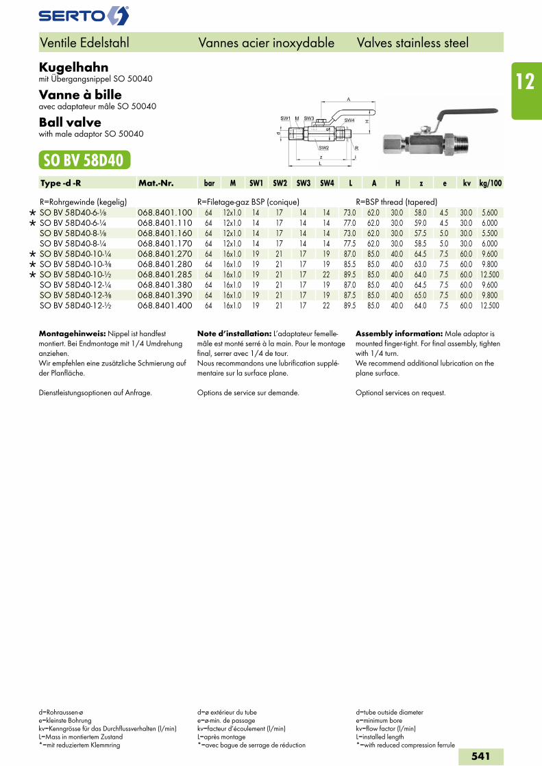
Kugelhahnmit Übergangsnippel SO 50040
Vanne à billeavec adaptateur mâle SO 50040
Ball valvewith male adaptor SO 50040
SO BV 58D40Type -d -R Mat.-Nr. bar M SW1 SW2 SW3 SW4 L A H z e kv kg/100 R=Rohrgewinde (kegelig) R=Filetage-gaz BSP (conique) R=BSP thread (tapered)
SO BV 58D40-6-1/8 068.8401.100 64 12x1.0 14 17 14 14 73.0 62.0 30.0 58.0 4.5 30.0 5.600 SO BV 58D40-6-1/4 068.8401.110 64 12x1.0 14 17 14 14 77.0 62.0 30.0 59.0 4.5 30.0 6.000 SO BV 58D40-8-1/8 068.8401.160 64 12x1.0 14 17 14 14 73.0 62.0 30.0 57.5 5.0 30.0 5.500 SO BV 58D40-8-1/4 068.8401.170 64 12x1.0 14 17 14 14 77.5 62.0 30.0 58.5 5.0 30.0 6.000
SO BV 58D40-10-1/4 068.8401.270 64 16x1.0 19 21 17 19 87.0 85.0 40.0 64.5 7.5 60.0 9.600 SO BV 58D40-10-3/8 068.8401.280 64 16x1.0 19 21 17 19 85.5 85.0 40.0 63.0 7.5 60.0 9.800 SO BV 58D40-10-1/2 068.8401.285 64 16x1.0 19 21 17 22 89.5 85.0 40.0 64.0 7.5 60.0 12.500 SO BV 58D40-12-1/4 068.8401.380 64 16x1.0 19 21 17 19 87.0 85.0 40.0 64.5 7.5 60.0 9.600 SO BV 58D40-12-3/8 068.8401.390 64 16x1.0 19 21 17 19 87.5 85.0 40.0 65.0 7.5 60.0 9.800 SO BV 58D40-12-1/2 068.8401.400 64 16x1.0 19 21 17 22 89.5 85.0 40.0 64.0 7.5 60.0 12.500
Montagehinweis: Nippel ist handfest montiert. Bei Endmontage mit 1/4 Umdrehung anziehen.Wir empfehlen eine zusätzliche Schmierung auf der Planfläche.
Dienstleistungsoptionen auf Anfrage.
Note d’installation: L’adaptateur femelle-mâle est monté serré à la main. Pour le montage final, serrer avec 1/4 de tour.Nous recommandons une lubrification supplé-mentaire sur la surface plane.
Options de service sur demande.
Assembly information: Male adaptor is mounted finger-tight. For final assembly, tighten with 1/4 turn.We recommend additional lubrication on the plane surface.
Optional services on request.
Ventile Edelstahl Vannes acier inoxydable Valves stainless steel
d=Rohraussen-øe=kleinste Bohrungkv=Kenngrösse für das Durchflussverhalten (l/min)L=Mass in montiertem Zustand*=mit reduziertem Klemmring
d=ø extérieur du tubee=ø-min. de passagekv=facteur d’écoulement (l/min)L=après montage*=avec bague de serrage de réduction
d=tube outside diametere=minimum borekv=flow factor (l/min)L=installed length*=with reduced compression ferrule
541
12
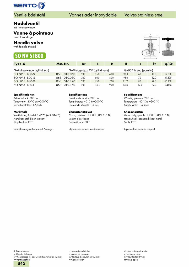
Nadelventilmit Innengewinde
Vanne à pointeauavec taraudage
Needle valvewith female thread
SO NV 51B00Type -G Mat.-Nr. bar L D H e kv kg/100 G=Rohrgewinde (zylindrisch) G=Filetage-gaz BSP (cylindrique) G=BSP thread (parallel)SO NV 51B00-3/8 068.1010.060 200 55.0 60.0 93.0 6.0 10.0 32.000SO NV 51B00-1/2 068.1010.080 200 60.0 60.0 96.0 7.0 12.0 41.500SO NV 51B00-3/4 068.1010.120 200 75.0 70.0 117.0 8.0 29.0 75.300SO NV 51B00-1 068.1010.160 200 100.0 90.0 138.0 12.0 32.0 154.000
SpezifikationenBetriebsdruck: 200 barTemperatur: -40°C bis +200°CSicherheitsfaktor: 1.5-fach
MerkmaleVentilkörper, Spindel: 1.4571 (AISI 316 Ti)Handrad: Stahlblech lackiertStopfbuchse: PTFE
Dienstleistungsoptionen auf Anfrage
SpécificationsPression de service: 200 barTempérature: -40°C à +200°CFacteur de sécurité: 1.5 fois
CharactéristiquesCorps, pointeau: 1.4571 (AISI 316 Ti)Volant: acier laquéPresse-étoupe: PTFE
Options de service sur demande
SpecificationsWorking pressure: 200 barTemperature: -40°C to +200°CSafety factor: 1.5 times
CharacteristicsValve body, spindle: 1.4571 (AISI 316 Ti)Handwheel: lacquered sheet metalSeals: PTFE
Optional services on request
Ventile Edelstahl Vannes acier inoxydable Valves stainless steel
d=Rohraussen-øe=kleinste Bohrungkv=Kenngrösse für das Durchflussverhalten (l/min)H=Ventil geöffnet
d=ø extérieur du tubee=ø-min. de passagekv=facteur d’écoulement (l/min)H=vanne ouvert
d=tube outside diametere=minimum borekv=flow factor (l/min)H=valve open
542
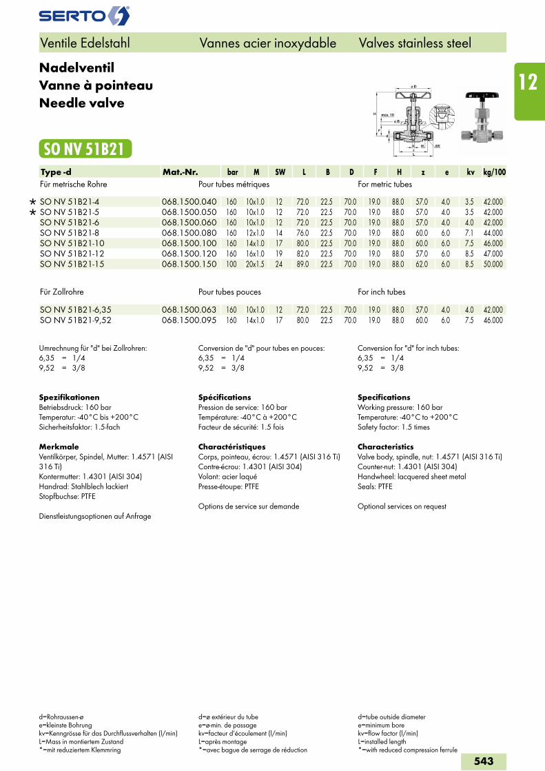
NadelventilVanne à pointeauNeedle valve
SO NV 51B21Type -d Mat.-Nr. bar M SW L B D F H z e kv kg/100Für metrische Rohre Pour tubes métriques For metric tubes
SO NV 51B21-4 068.1500.040 160 10x1.0 12 72.0 22.5 70.0 19.0 88.0 57.0 4.0 3.5 42.000 SO NV 51B21-5 068.1500.050 160 10x1.0 12 72.0 22.5 70.0 19.0 88.0 57.0 4.0 3.5 42.000 SO NV 51B21-6 068.1500.060 160 10x1.0 12 72.0 22.5 70.0 19.0 88.0 57.0 4.0 4.0 42.000 SO NV 51B21-8 068.1500.080 160 12x1.0 14 76.0 22.5 70.0 19.0 88.0 60.0 6.0 7.1 44.000 SO NV 51B21-10 068.1500.100 160 14x1.0 17 80.0 22.5 70.0 19.0 88.0 60.0 6.0 7.5 46.000 SO NV 51B21-12 068.1500.120 160 16x1.0 19 82.0 22.5 70.0 19.0 88.0 57.0 6.0 8.5 47.000 SO NV 51B21-15 068.1500.150 100 20x1.5 24 89.0 22.5 70.0 19.0 88.0 62.0 6.0 8.5 50.000
Für Zollrohre Pour tubes pouces For inch tubes
SO NV 51B21-6,35 068.1500.063 160 10x1.0 12 72.0 22.5 70.0 19.0 88.0 57.0 4.0 4.0 42.000 SO NV 51B21-9,52 068.1500.095 160 14x1.0 17 80.0 22.5 70.0 19.0 88.0 60.0 6.0 7.5 46.000
Umrechnung für "d" bei Zollrohren:6,35 = 1/49,52 = 3/8
Conversion de "d" pour tubes en pouces:6,35 = 1/49,52 = 3/8
Conversion for "d" for inch tubes:6,35 = 1/49,52 = 3/8
SpezifikationenBetriebsdruck: 160 barTemperatur: -40°C bis +200°CSicherheitsfaktor: 1.5-fach
MerkmaleVentilkörper, Spindel, Mutter: 1.4571 (AISI 316 Ti)Kontermutter: 1.4301 (AISI 304)Handrad: Stahlblech lackiertStopfbuchse: PTFE
Dienstleistungsoptionen auf Anfrage
SpécificationsPression de service: 160 barTempérature: -40°C à +200°CFacteur de sécurité: 1.5 fois
CharactéristiquesCorps, pointeau, écrou: 1.4571 (AISI 316 Ti)Contre-écrou: 1.4301 (AISI 304)Volant: acier laquéPresse-étoupe: PTFE
Options de service sur demande
SpecificationsWorking pressure: 160 barTemperature: -40°C to +200°CSafety factor: 1.5 times
CharacteristicsValve body, spindle, nut: 1.4571 (AISI 316 Ti)Counter-nut: 1.4301 (AISI 304)Handwheel: lacquered sheet metalSeals: PTFE
Optional services on request
Ventile Edelstahl Vannes acier inoxydable Valves stainless steel
d=Rohraussen-øe=kleinste Bohrungkv=Kenngrösse für das Durchflussverhalten (l/min)L=Mass in montiertem Zustand*=mit reduziertem Klemmring
d=ø extérieur du tubee=ø-min. de passagekv=facteur d’écoulement (l/min)L=après montage*=avec bague de serrage de réduction
d=tube outside diametere=minimum borekv=flow factor (l/min)L=installed length*=with reduced compression ferrule
543
12
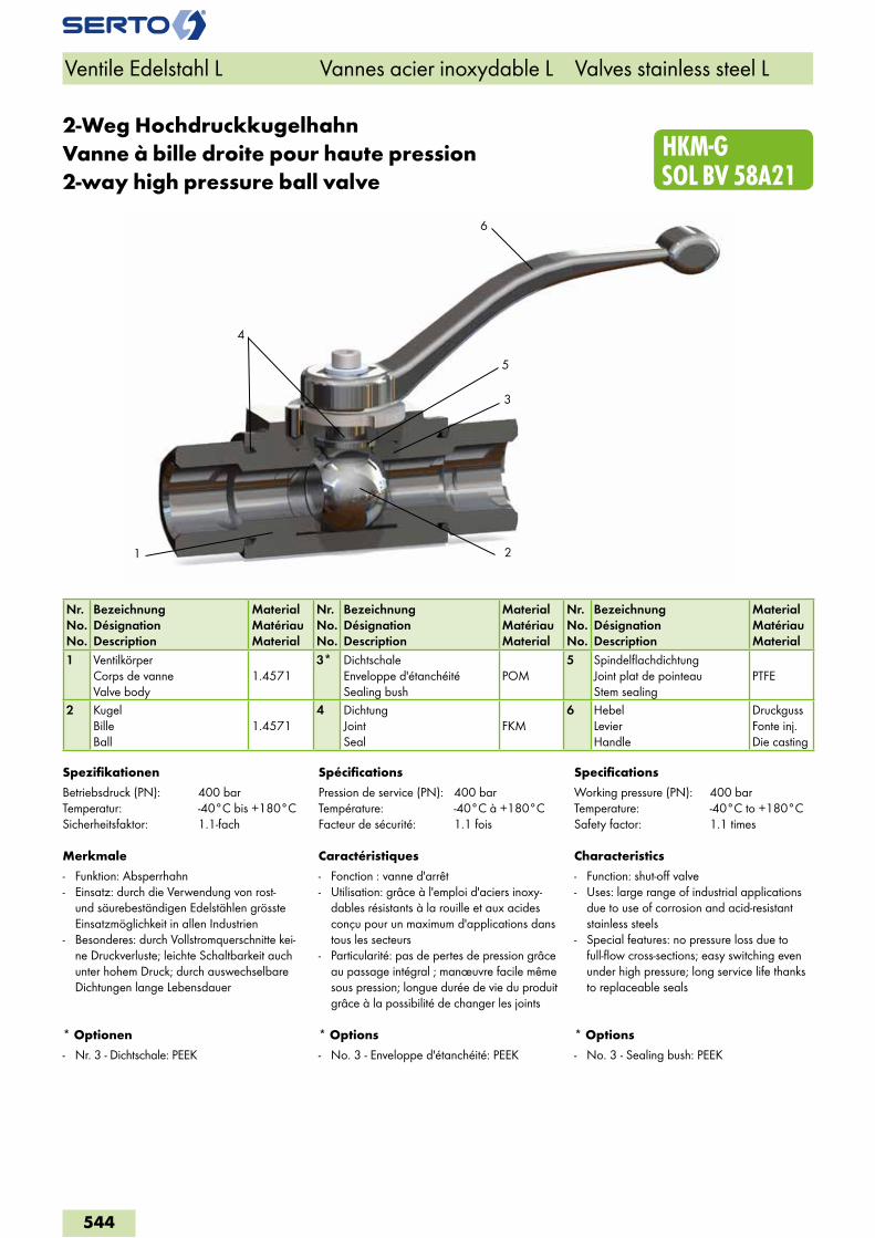
4
HKM-G SOL BV 58A21
2
6
1
5
3
2-Weg HochdruckkugelhahnVanne à bille droite pour haute pression2-way high pressure ball valve
Nr.No.No.
BezeichnungDésignationDescription
MaterialMatériauMaterial
Nr.No.No.
BezeichnungDésignationDescription
MaterialMatériauMaterial
Nr.No.No.
BezeichnungDésignationDescription
MaterialMatériauMaterial
1 VentilkörperCorps de vanneValve body
1.45713* Dichtschale
Enveloppe d'étanchéitéSealing bush
POM5 Spindelflachdichtung
Joint plat de pointeauStem sealing
PTFE
2 KugelBilleBall
1.45714 Dichtung
JointSeal
FKM6 Hebel
LevierHandle
DruckgussFonte inj.Die casting
Spezifikationen
Betriebsdruck (PN): 400 barTemperatur: -40°C bis +180°CSicherheitsfaktor: 1.1-fach
Merkmale
- Funktion: Absperrhahn- Einsatz: durch die Verwendung von rost-
und säurebeständigen Edelstählen grösste Einsatzmöglichkeit in allen Industrien
- Besonderes: durch Vollstromquerschnitte kei-ne Druckverluste; leichte Schaltbarkeit auch unter hohem Druck; durch auswechselbare Dichtungen lange Lebensdauer
* Optionen
- Nr. 3 - Dichtschale: PEEK
Spécifications
Pression de service (PN): 400 barTempérature: -40°C à +180°CFacteur de sécurité: 1.1 fois
Caractéristiques
- Fonction : vanne d'arrêt - Utilisation: grâce à l'emploi d'aciers inoxy-
dables résistants à la rouille et aux acides conçu pour un maximum d'applications dans tous les secteurs
- Particularité: pas de pertes de pression grâce au passage intégral ; manœuvre facile même sous pression; longue durée de vie du produit grâce à la possibilité de changer les joints
* Options
- No. 3 - Enveloppe d'étanchéité: PEEK
Specifications
Working pressure (PN): 400 barTemperature: -40°C to +180°CSafety factor: 1.1 times
Characteristics
- Function: shut-off valve- Uses: large range of industrial applications
due to use of corrosion and acid-resistant stainless steels
- Special features: no pressure loss due to full-flow cross-sections; easy switching even under high pressure; long service life thanks to replaceable seals
* Options
- No. 3 - Sealing bush: PEEK
Ventile Edelstahl L Vannes acier inoxydable L Valves stainless steel L
544
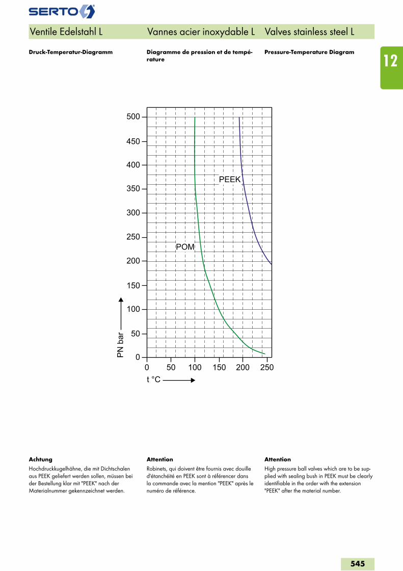
0
50
0 50 100 150 200 250
100
150
200
250
300
350
400
450
500
t °C
PN
bar
POM
PEEK
Ventile Edelstahl L Vannes acier inoxydable L Valves stainless steel L
Attention
Robinets, qui doivent être fournis avec douille d'étanchéité en PEEK sont à référencer dans la commande avec la mention "PEEK" après le numéro de référence.
Attention
High pressure ball valves which are to be sup-plied with sealing bush in PEEK must be clearly identifiable in the order with the extension "PEEK" after the material number.
Achtung
Hochdruckkugelhähne, die mit Dichtschalen aus PEEK geliefert werden sollen, müssen bei der Bestellung klar mit "PEEK" nach der Materialnummer gekennzeichnet werden.
Diagramme de pression et de tempé-rature
Pressure-Temperature DiagramDruck-Temperatur-Diagramm
545
12
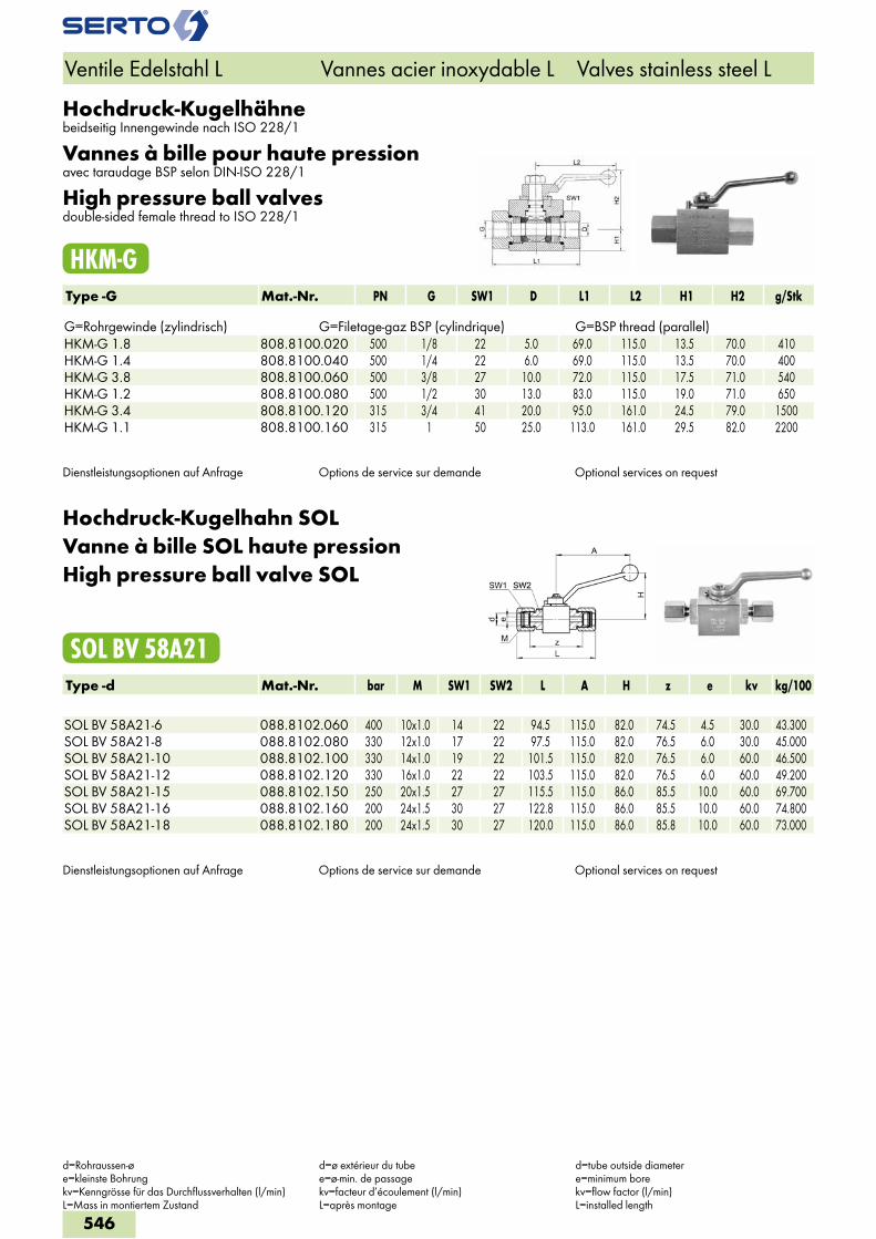
Hochdruck-Kugelhähnebeidseitig Innengewinde nach ISO 228/1
Vannes à bille pour haute pressionavec taraudage BSP selon DIN-ISO 228/1
High pressure ball valvesdouble-sided female thread to ISO 228/1
HKM-GType -G Mat.-Nr. PN G SW1 D L1 L2 H1 H2 g/Stk G=Rohrgewinde (zylindrisch) G=Filetage-gaz BSP (cylindrique) G=BSP thread (parallel)HKM-G 1.8 808.8100.020 500 1/8 22 5.0 69.0 115.0 13.5 70.0 410HKM-G 1.4 808.8100.040 500 1/4 22 6.0 69.0 115.0 13.5 70.0 400HKM-G 3.8 808.8100.060 500 3/8 27 10.0 72.0 115.0 17.5 71.0 540HKM-G 1.2 808.8100.080 500 1/2 30 13.0 83.0 115.0 19.0 71.0 650HKM-G 3.4 808.8100.120 315 3/4 41 20.0 95.0 161.0 24.5 79.0 1500HKM-G 1.1 808.8100.160 315 1 50 25.0 113.0 161.0 29.5 82.0 2200
Dienstleistungsoptionen auf Anfrage Options de service sur demande Optional services on request
Hochdruck-Kugelhahn SOLVanne à bille SOL haute pressionHigh pressure ball valve SOL
SOL BV 58A21Type -d Mat.-Nr. bar M SW1 SW2 L A H z e kv kg/100 SOL BV 58A21-6 088.8102.060 400 10x1.0 14 22 94.5 115.0 82.0 74.5 4.5 30.0 43.300SOL BV 58A21-8 088.8102.080 330 12x1.0 17 22 97.5 115.0 82.0 76.5 6.0 30.0 45.000SOL BV 58A21-10 088.8102.100 330 14x1.0 19 22 101.5 115.0 82.0 76.5 6.0 60.0 46.500SOL BV 58A21-12 088.8102.120 330 16x1.0 22 22 103.5 115.0 82.0 76.5 6.0 60.0 49.200SOL BV 58A21-15 088.8102.150 250 20x1.5 27 27 115.5 115.0 86.0 85.5 10.0 60.0 69.700SOL BV 58A21-16 088.8102.160 200 24x1.5 30 27 122.8 115.0 86.0 85.5 10.0 60.0 74.800SOL BV 58A21-18 088.8102.180 200 24x1.5 30 27 120.0 115.0 86.0 85.8 10.0 60.0 73.000
Dienstleistungsoptionen auf Anfrage Options de service sur demande Optional services on request
Ventile Edelstahl L Vannes acier inoxydable L Valves stainless steel L
d=Rohraussen-øe=kleinste Bohrungkv=Kenngrösse für das Durchflussverhalten (l/min)L=Mass in montiertem Zustand
d=ø extérieur du tubee=ø-min. de passagekv=facteur d’écoulement (l/min)L=après montage
d=tube outside diametere=minimum borekv=flow factor (l/min)L=installed length
546
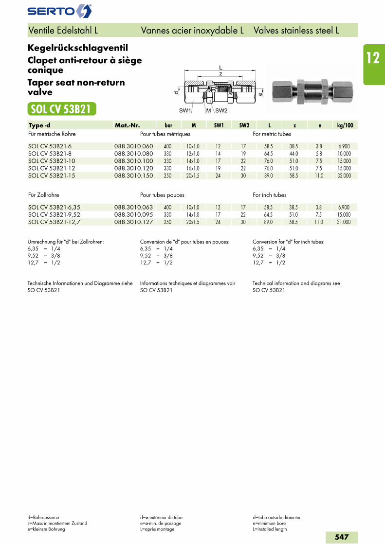
KegelrückschlagventilClapet anti-retour à siège coniqueTaper seat non-return valve
SOL CV 53B21Type -d Mat.-Nr. bar M SW1 SW2 L z e kg/100Für metrische Rohre Pour tubes métriques For metric tubes SOL CV 53B21-6 088.3010.060 400 10x1.0 12 17 58.5 38.5 3.8 6.900SOL CV 53B21-8 088.3010.080 330 12x1.0 14 19 64.5 44.0 5.8 10.000SOL CV 53B21-10 088.3010.100 330 14x1.0 17 22 76.0 51.0 7.5 15.000SOL CV 53B21-12 088.3010.120 330 16x1.0 19 22 76.0 51.0 7.5 15.000SOL CV 53B21-15 088.3010.150 250 20x1.5 24 30 89.0 58.5 11.0 32.000
Für Zollrohre Pour tubes pouces For inch tubes SOL CV 53B21-6,35 088.3010.063 400 10x1.0 12 17 58.5 38.5 3.8 6.900SOL CV 53B21-9,52 088.3010.095 330 14x1.0 17 22 64.5 51.0 7.5 15.000SOL CV 53B21-12,7 088.3010.127 250 20x1.5 24 30 89.0 58.5 11.0 31.000
Umrechnung für "d" bei Zollrohren:6,35 = 1/49,52 = 3/812,7 = 1/2
Conversion de "d" pour tubes en pouces:6,35 = 1/49,52 = 3/812,7 = 1/2
Conversion for "d" for inch tubes:6,35 = 1/49,52 = 3/812,7 = 1/2
Technische Informationen und Diagramme siehe SO CV 53B21
Informations techniques et diagrammes voir SO CV 53B21
Technical information and diagrams see SO CV 53B21
Ventile Edelstahl L Vannes acier inoxydable L Valves stainless steel L
d=Rohraussen-øL=Mass in montiertem Zustande=kleinste Bohrung
d=ø extérieur du tubee=ø-min. de passageL=après montage
d=tube outside diametere=minimum boreL=installed length
547
12
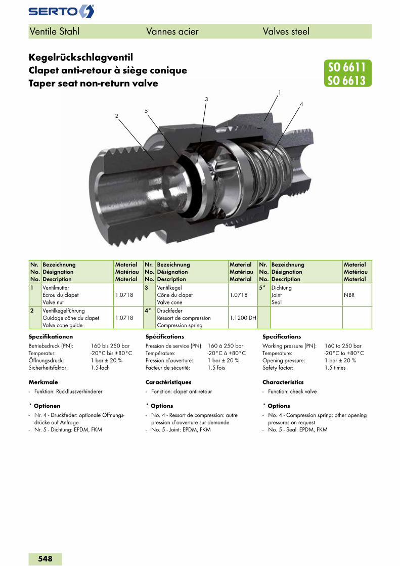
2
43
SO 6611SO 6613
1
5
KegelrückschlagventilClapet anti-retour à siège coniqueTaper seat non-return valve
Nr.No.No.
BezeichnungDésignationDescription
MaterialMatériauMaterial
Nr.No.No.
BezeichnungDésignationDescription
MaterialMatériauMaterial
Nr.No.No.
BezeichnungDésignationDescription
MaterialMatériauMaterial
1 VentilmutterÉcrou du clapetValve nut
1.07183 Ventilkegel
Cône du clapetValve cone
1.07185* Dichtung
JointSeal
NBR
2 VentilkegelführungGuidage cône du clapetValve cone guide
1.07184* Druckfeder
Ressort de compressionCompression spring
1.1200 DH
Spezifikationen
Betriebsdruck (PN): 160 bis 250 barTemperatur: -20°C bis +80°CÖffnungsdruck: 1 bar ± 20 %Sicherheitsfaktor: 1.5-fach
Merkmale
- Funktion: Rückflussverhinderer
* Optionen
- Nr. 4 - Druckfeder: optionale Öffnungs- drücke auf Anfrage
- Nr. 5 - Dichtung: EPDM, FKM
Spécifications
Pression de service (PN): 160 à 250 barTempérature: -20°C à +80°CPression d‘ouverture: 1 bar ± 20 %Facteur de sécurité: 1.5 fois
Caractéristiques
- Fonction: clapet anti-retour
* Options
- No. 4 - Ressort de compression: autre pression d‘ouverture sur demande
- No. 5 - Joint: EPDM, FKM
Specifications
Working pressure (PN): 160 to 250 barTemperature: -20°C to +80°COpening pressure: 1 bar ± 20 %Safety factor: 1.5 times
Characteristics
- Function: check valve
* Options
- No. 4 - Compression spring: other opening pressures on request
- No. 5 - Seal: EPDM, FKM
Ventile Stahl Vannes acier Valves steel
548
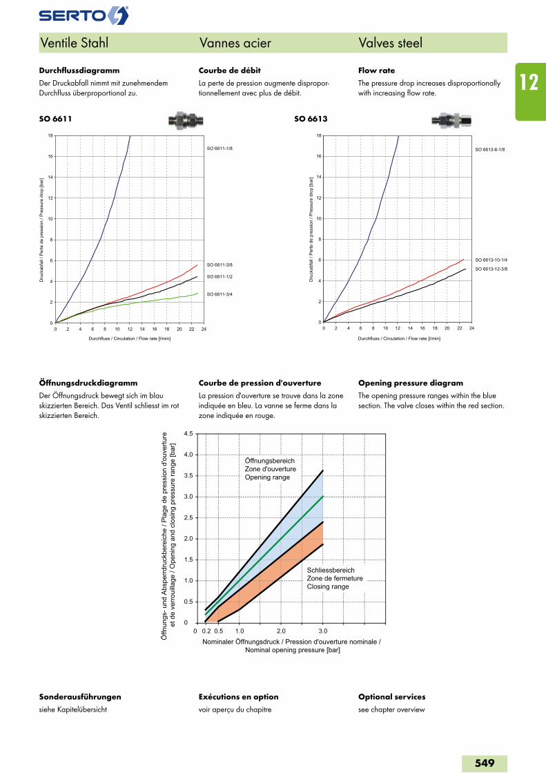
SO 6611 SO 6613
Ventile Stahl Vannes acier Valves steel
Exécutions en option
voir aperçu du chapitre
Optional services
see chapter overview
Sonderausführungen
siehe Kapitelübersicht
0
2
4
6
8
10
12
14
16
18
0 2 4 6 8 10 12 14 16 18 20 22 24
Durchfluss / Circulation / Flow rate [l/min]
Dru
ckab
fall
/ Per
te d
e pr
essi
on /
Pre
ssur
e dr
op [b
ar]
SO 6611-1/8
SO 6611-3/8
SO 6611-1/2
SO 6611-3/4
0
2
4
6
8
10
12
14
16
18
0 2 4 6 8 10 12 14 16 18 20 22 24
Durchfluss / Circulation / Flow rate [l/min]
Dru
ckab
fall
/ Per
te d
e pr
essi
on /
Pre
ssur
e dr
op [b
ar]
SO 6613-6-1/8
SO 6613-10-1/4
SO 6613-12-3/8
Courbe de débit
La perte de pression augmente dispropor-tionnellement avec plus de débit.
Flow rate
The pressure drop increases disproportionally with increasing flow rate.
Durchflussdiagramm
Der Druckabfall nimmt mit zunehmendem Durchfluss überproportional zu.
Courbe de pression d'ouverture
La pression d'ouverture se trouve dans la zone indiquée en bleu. La vanne se ferme dans la zone indiquée en rouge.
Opening pressure diagram
The opening pressure ranges within the blue section. The valve closes within the red section.
Öffnungsdruckdiagramm
Der Öffnungsdruck bewegt sich im blau skizzierten Bereich. Das Ventil schliesst im rot skizzierten Bereich.
0
0.5
1.0
1.5
2.0
2.5
3.0
3.5
4.0
4.5
0 0.50.2 1.0 2.0 3.0
Öffn
ungs
- und
Abs
perrd
ruck
bere
iche
/ Pl
age
de p
ress
ion
d'ou
vertu
re
et d
e ve
rroui
llage
/ O
peni
ng a
nd c
losi
ng p
ress
ure
rang
e [b
ar]
Nominaler Öffnungsdruck / Pression d'ouverture nominale / Nominal opening pressure [bar]
ÖffnungsbereichZone d'ouvertureOpening range
SchliessbereichZone de fermetureClosing range
549
12
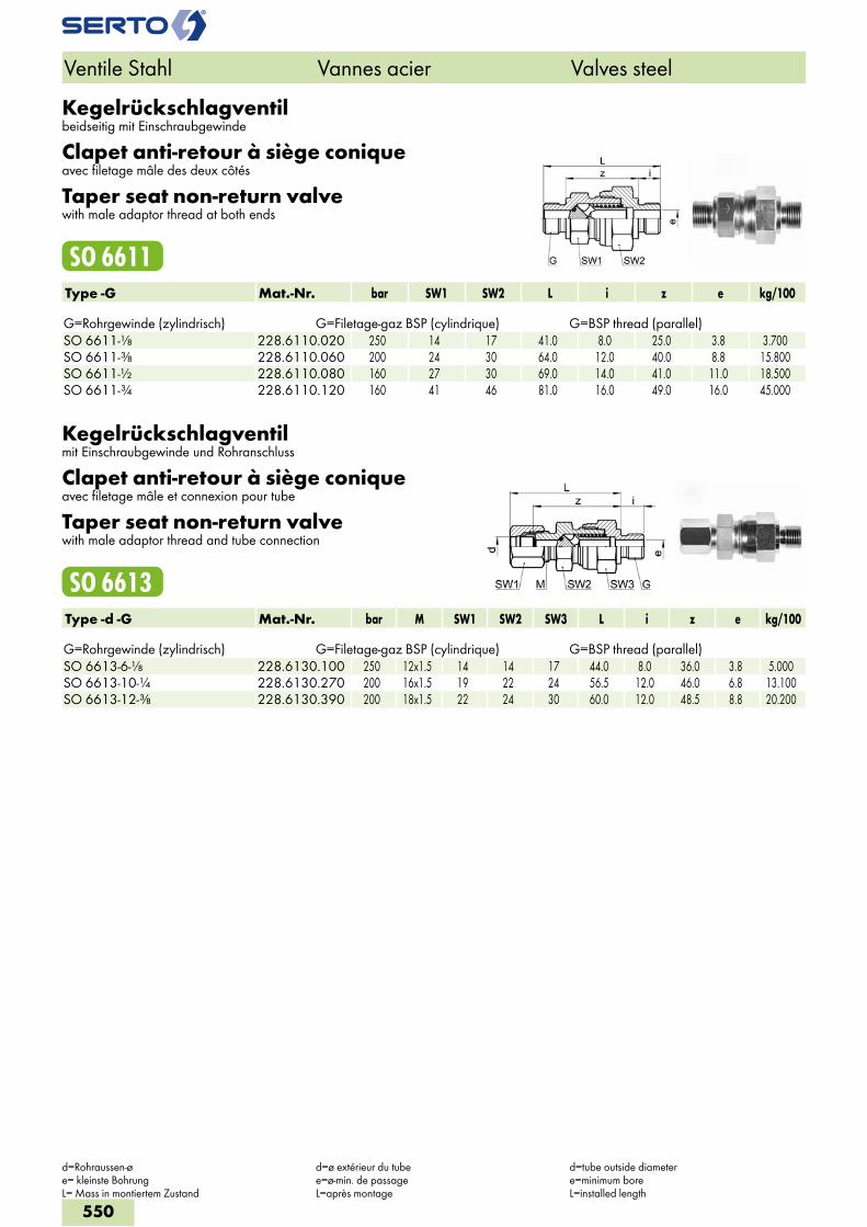
Kegelrückschlagventilbeidseitig mit Einschraubgewinde
Clapet anti-retour à siège coniqueavec filetage mâle des deux côtés
Taper seat non-return valvewith male adaptor thread at both ends
SO 6611Type -G Mat.-Nr. bar SW1 SW2 L i z e kg/100 G=Rohrgewinde (zylindrisch) G=Filetage-gaz BSP (cylindrique) G=BSP thread (parallel)SO 6611-1/8 228.6110.020 250 14 17 41.0 8.0 25.0 3.8 3.700SO 6611-3/8 228.6110.060 200 24 30 64.0 12.0 40.0 8.8 15.800SO 6611-1/2 228.6110.080 160 27 30 69.0 14.0 41.0 11.0 18.500SO 6611-3/4 228.6110.120 160 41 46 81.0 16.0 49.0 16.0 45.000
Kegelrückschlagventilmit Einschraubgewinde und Rohranschluss
Clapet anti-retour à siège coniqueavec filetage mâle et connexion pour tube
Taper seat non-return valvewith male adaptor thread and tube connection
SO 6613Type -d -G Mat.-Nr. bar M SW1 SW2 SW3 L i z e kg/100 G=Rohrgewinde (zylindrisch) G=Filetage-gaz BSP (cylindrique) G=BSP thread (parallel)SO 6613-6-1/8 228.6130.100 250 12x1.5 14 14 17 44.0 8.0 36.0 3.8 5.000SO 6613-10-1/4 228.6130.270 200 16x1.5 19 22 24 56.5 12.0 46.0 6.8 13.100SO 6613-12-3/8 228.6130.390 200 18x1.5 22 24 30 60.0 12.0 48.5 8.8 20.200
Ventile Stahl Vannes acier Valves steel
d=Rohraussen-ø e= kleinste BohrungL= Mass in montiertem Zustand
d=ø extérieur du tube e=ø-min. de passageL=après montage
d=tube outside diameter e=minimum boreL=installed length
550
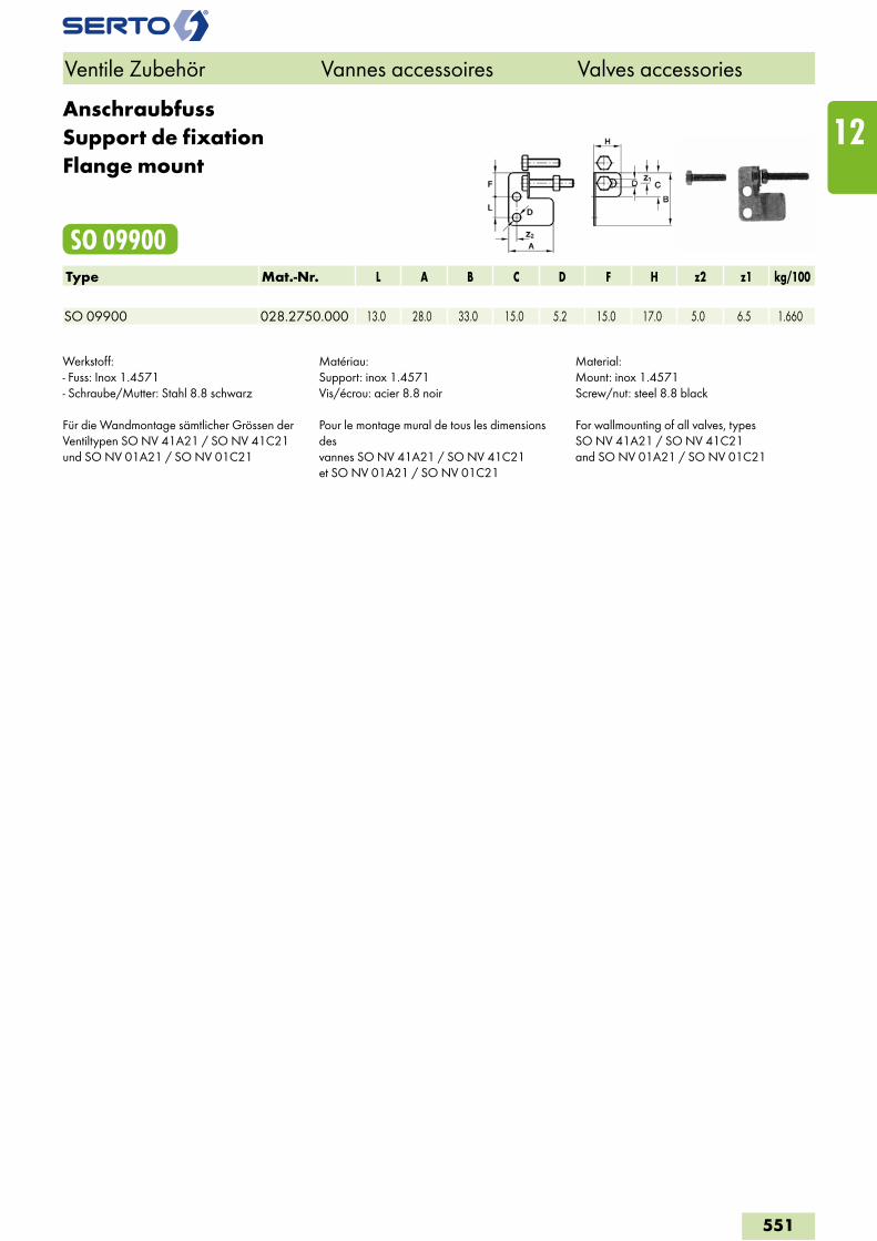
AnschraubfussSupport de fixationFlange mount
SO 09900Type Mat.-Nr. L A B C D F H z2 z1 kg/100 SO 09900 028.2750.000 13.0 28.0 33.0 15.0 5.2 15.0 17.0 5.0 6.5 1.660
Werkstoff: - Fuss: Inox 1.4571- Schraube/Mutter: Stahl 8.8 schwarz
Für die Wandmontage sämtlicher Grössen derVentiltypen SO NV 41A21 / SO NV 41C21und SO NV 01A21 / SO NV 01C21
Matériau:Support: inox 1.4571Vis/écrou: acier 8.8 noir
Pour le montage mural de tous les dimensions desvannes SO NV 41A21 / SO NV 41C21et SO NV 01A21 / SO NV 01C21
Material:Mount: inox 1.4571Screw/nut: steel 8.8 black
For wallmounting of all valves, typesSO NV 41A21 / SO NV 41C21and SO NV 01A21 / SO NV 01C21
Ventile Zubehör Vannes accessoires Valves accessories
551
12
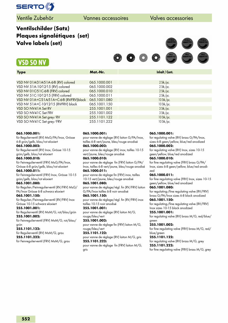
Ventilschilder (Satz)Plaques signalétiques (set)Valve labels (set)
VSD SO NVType Mat.-Nr. Inhalt / Cont. VSD NV 01A/31A/51A-6/8 (RV) colored 065.1000.001 2 Stk./pc.VSD NV 51A-10/12/15 (RV) colored 065.1000.002 2 Stk./pc.VSD NV 01C/51C-6/8 (FRV) colored 065.1000.010 2 Stk./pc.VSD NV 51C-10/12/15 (FRV) colored 065.1000.011 2 Stk./pc.VSD NV 01A+C/31A/51A+C-6/8 (RV/FRV)black 065.1001.080 10 Stk./pc.VSD NV 51A+C-10/12/15 (RV/FRV) black 065.1001.150 10 Stk./pc.VSD SO NV41A Set RV 255.1001.001 3 Stk./pc.VSD SO NV41C Set FRV 255.1001.002 3 Stk./pc.VSD SO NV41A Set grey / RV 255.1101.122 10 Stk./pc.VSD SO NV41C Set grey / FRV 255.1101.222 10 Stk./pc.
065.1000.001:für Regulierventil (RV) MsG/PA/Inox, Grösse 6-8 grün/gelb, blau/rot eloxiert065.1000.002:für Regulierventil (RV) Inox, Grösse 10-15 grün/gelb, blau/rot eloxiert065.1000.010:für Feinregulierventil (FRV) MsG/PA/Inox, Grösse 6-8 grün/gelb, blau/rot eloxiert065.1000.011:für Feinregulierventil (FRV) Inox, Grösse 10-15 grün/gelb, blau/rot eloxiert065.1001.080:für Regulier-/Feinregulierventil (RV/FRV) MsG/PA/Inox Grösse 6-8 schwarz eloxiert065.1001.150: für Regulier-/Feinregulierventil (RV/FRV) Inox Grösse 10-15 schwarz eloxiert 255.1001.001:für Regulierventil (RV) MsM/G, rot/blau/grün255.1001.002:für Feinregulierventil (FRV) MsM/G, rot/blau/grün255.1101.122: für Regulierventil (RV) MsM/G, grau255.1101.222:für Feinregulierventil (FRV) MsM/G, grau
065.1000.001:pour vanne de réglage (RV) laiton G/PA/Inox, tailles 6-8 vert/jaune, bleu/rouge anodisé065.1000.002:pour vanne de réglage (RV) inox, tailles 10-15 vert/jaune, bleu/rouge anodisé065.1000.010:pour vanne de réglage fin (FRV) laiton G/PA/Inox, tailles 6-8 vert/jaune, bleu/rouge anodisé065.1000.011:pour vanne de réglage fin (FRV) inox, tailles 10-15 vert/jaune, bleu/rouge anodisé065.1001.080:pour vanne de réglage/régl. fin (RV/FRV) laiton G/PA/Inox tailles 6-8 noir anodisé065.1001.150: pour vanne de réglage/régl. fin (RV/FRV) inox tailles 10-15 noir anodisé255.1001.001:pour vanne de réglage (RV) laiton M/G, rouge/bleu/vert255.1001.002:pour vanne de réglage fin (FRV) laiton M/G, rouge/bleu/vert255.1101.122: pour vanne de réglage (RV) laiton M/G, gris255.1101.222:pour vanne de réglage fin (FRV) laiton M/G, gris
065.1000.001:for regulating valve (RV) brass G/PA/Inox, sizes 6-8 geen/yellow, blue/red anodized065.1000.002:for regulating valve (RV) Inox, sizes 10-15 geen/yellow, blue/red anodized065.1000.010:for fine regulating valve (FRV) brass G/PA/Inox, sizes 6-8 geen/yellow, blue/red anodi-zed065.1000.011:for fine regulating valve (FRV) Inox, sizes 10-15 geen/yellow, blue/red anodized065.1001.080:for regulating-/fine regulating valve (RV/FRV) brass G/PA/Inox sizes 6-8 black anodized065.1001.150: for regulating-/fine regulating valve (RV/FRV) Inox sizes 10-15 black anodized255.1001.001:for regulating valve (RV) brass M/G, red/blue/green255.1001.002:for fine regulating valve (FRV) brass M/G, red/blue/green255.1101.122: for regulating valve (RV) brass M/G, grey255.1101.222:for fine regulating valve (FRV) brass M/G, grey
Ventile Zubehör Vannes accessoires Valves accessories
552