Embed Size (px)
Citation preview

International Journal of Mine Water, Vol.4, No.4 (1985), pp.21-35 Printed in Madrid, Spain
VENTILATION SHAFT WATER INFLOW CONTROL
ROSSARDEN TIN MINE~ TASMANIA~ AUSTRALIA
Mr Stephen Hancock B.Sc. (Melb), Cert. E.H. (NSW), M. Aus IMM, FAIG, MIWES
Principal Consultant
Australian Groundwater Consultant Pry Ltd, Melbourne Victoria Australia
ABSTRACT
The Rossarden tin and tungsten mine in Tasmania Australia was opened in 1923 and was operated until recently by Aberfoyle Ltd. The last major development operation in this mine was the construction of a 1.2m diameter ventilation shaft to permit the expansion of workings in a new orebody, "The Lutwyche Prospect", 380m below ground level. Because of a long history of reasonably dry mine workings and for reason of economics it was decided to construct the new ventilation shaft using the raise bore pilot hole as an investigation hole in advance of raise boring operations. The only water inflows expected were near the bottom where water had been intersected in mineral exploration holes. This paper examines the course of the shaft construction operations, the problems of water inflow and analyses the impact of assumptions made in advance on likely ground conditions on the project.
INTRODUCTION
In 1978 the Rossarden tin and tungsten mine in north west Tasmania, Australia (Figure 1), then operated by Aberfoyle Tin Ltd., was the subject of a ventilation shaft development project to serve a new mine development known as the Lutwyche ~roject. The shaft was designed to permit an upcast airflow of 850m~/min to be exhausted to the surface and was to be completed at 1.22m diameter over a full depth of 385m.
The material to be penetrated included fractured rocks known to be water bearing at depth. If an inflow of greater than 4.0 L/s were to exist into the shaft on completion, adequate ventilation for the development would be lost and any remedial work would be expensive. Further, any significantly larger inflow could place stress on the mine drainage system as well as impose a heavy penalty on mining costs.
21

~2rASMANIA
Ben /omond National I~rk
) . ~ - - - ~ / ' ~ / " I TO East Coast
~ / " (. ~-... ~" -,, _---. _._ F , - - . ~ i , - , , _ - . . ~ " ~ - ~ , ' - ~ J ~ ' ~ S
j - T o , . a . ~ . IJl " \ ~ l ~ " "----
f z , . , f f -~ '~ "~ROS~N _ d .'reEastCoast r / g t " . . Z
. . . #, p ' - < ~ >~.,., v !/
J LOCALITY PLAN To L am l i l i l oa
.olart F I G U R E 1 22

GEOLOGY
The tin/tungsten orebody at Rossarden is associated with quartz veins up to 0.5m wide dipping variously at between 25 ~ and 85 ~ in a faulted host rock which comprises a highly siliceous competant sub-greywacke with broadly spaced but interconnected fractures.
HYDROGEOLOGY
While most of the development in the Rossarden mine was dry, or not significantly wet, the Lutwyche orebody area was very wet. Twenty out of 37 holes intersected pressure water with hydrostatic heads measured at between 3,500 and 3,800 kPa. The variations in pressure observed have been determined, by three dimensional fracture and structural analysis, to derive from leakages occurring into certain fractures intersected by mine workings (Figure 2); otherwise all pressures are considered to be uniform and to represent full hydrostatic head back to surface.
Sustained ,flows derived from 38mm diameter (EX) exploration holes, vary substantially. All holes show initial high burst flows, but these diminish in time, in some cases to less than 1.0L/s within the first minute~ Those holes which sustain high inflows on open discharge are those which intersect fractures east of the "Hanging Wall Vein" and the "Zone of Healed Faulting" The flows from this section range from 1.0 to over ii L/s per hole.
Little data on the nature of the water bearing fractures is available from the holes because the hydrostatic head exceeded the hydraulic feed capabilities of the diamond coring rigs in use.
Inspection of partly grouted water bearing zones exposed by mine development, show them to comprise a multitude of fractures of varying depths and strikes in broad extensive broken rock zones. Within these broken zones as little as one metre of rock thickness is sufficient to withstand full hydrostatic heads; but the fracture conduit orientations vary from one plane to another in an undetermined manner.
Hydraulic pressure continuity exists within the fracture zones, from one to another but has been shown by pressure decline and flow tests to be indirect.
Variable discharges from the holes derive in part from variations in the hydraulic conductivity of the fractures feeding the holes, but may also derive from the continuity of the fracture zones themselves within dyke intrusions, effects of alteration zones and subsequent faulting.
It has been concluded that, even though the faulting and fracturing post dates the mineralization, the Hanging Wall Vein and the Zone of Healed Faulting (Figure 2) have affeated the persistance of the fractures as hydrological conduits and fractures east of these structures generally exhibit high sustained flows while those to the south and west only show high initial burst flows.
23
N
f .
\, "4
l Imoll \ sm411
LEGEND:
2"O INFLOW ( L / I )
WET SECTION
DRILL HOLE N.R. NOT RECORDED
NOTE : DRILL HOLE VERTICM. ANGLES NOT PRESENTED
0"4
I1"0
N.R.
, ,I ~
3.2
VENTILATION /SN.T
.RS.(T..OUGH ,,,,,0
; \ /
ABERFO SHAFT
' Z " METRES (;~ 0 IO 20 30 40 50 �9 "11 I I I I | i ~)' SCALE ( : r - -4 GO
LUTWYCHE PROSPECT GEOLOGY 24 FIGURE 2

The Hanging Well Vein and Zone of Healed Faulting dip SW to WSW at 55 - 60 ~ , thus fracturing to the west overlies the present mine workings, while those to the east under lie these structures. This matches observed evidence from workings that flows east of the structures emerge from the lower side. For pressure, hydraulic continuity and storage continuity to be maintained from the surface to depth below the Hanging Well Vein and Zone of Healed Faulting, another structure must exist. This structure has not been identified.
IMPLICATIONS OF THE HYDROGEOLOGY TO MINING
The existing mine dewatering system included a short term removal capacity of 70 L/s but a long term capacity of only 45 L/s due to limited capacity in the second stage pumps.
The Lutwyche Prospect development inflows were already up to 19 L/s. Additional large water inflows from new mine developments, as from a ventilation shaft, could not easily be accommodated without substantial system upgrading.
The conclusion reached was that any operation which would require a major upgrading of the mine drainage system could not be economically justified. Grouting of the permeability conduits would have to be undertaken or mining abandoned in this are~until economic parameters became more favourable.
MINE GROUTING
Past experience of grouting in the mine had not been good. Back analysis of grouting operations using normal Portland Cement formulations showed then to have been carried out on an "ad hoe" basis and as a reaction to inflows already encountered. Also, while only low grouting pressures were required, much grout dilution occurred due to the existing rapid movement of waters in the fractures where grouting was being attempted. As a consequence poor results were achieved.
The first planned exercise in grouting undertaken in advance of inflow problems for the Lutwyche Prospect was to be the ventilation shaft project.
VENTILATION SHAFT PROJECT
The ventilation shaft was proposed to intersect the Lutwyche Project level immediately adjacent to the zone of Healed Faulting (Figure 2). No geological information existed on the section to be intersected by the shaft. No investigation holes had been drilled for reason of economics.
The proposed construction procedure was to raise bore the ventilation shaft to 1.2m diameter from a depth of 380m to surface using a Robins
25

61R Raise Boring machine. A pilot hole at 28Omm diameter was required in advance to permit running of the raise bore rods. This pilot hole was to be drilled from the surface using the Raise Bore machine and down hole hammers operating with 1.83m~/s, 60OkPa air. This hole was commenced immediately adjacent to the foot wall outcrop and was drilled entirely within the orebody.
Any water inflows intersected would
be a problem in drilling the pilot hole due to hammer back pressure,
become additive to mine water on completion,
could be expected to increase by a factor of greater than 4 when the shaft was opened up to full diameter and
would diminish the performance of the shaft as an upcast induced flow exhaust structure.
The diminution of the exhaust fan performance derives from the weight of water which accumulates in the return air flow column between the point of entry and the discharge vent.
The upshaft air velocity within the ventilation shaft at 850m3/min would be 12.53m/sec. on average and any water entering the shaft is tending to fall at 9.75m/sec. Thus the relative removal rate of water without taking drop evaporation into account is only 2.78m/sec.
Water entering near the bottom of the shaft, at say 30Ore, takes over 100 seconds to vent at the surface and the total column weight is increased by this accummulation. This weight absorbs a significant amount of the fan motor energy and hence the capacity to move the air.
In the event ths~t the air flow rate is declined to approach the drop rate of the water then the water load on the fan motor can build rapidly and stall the fan and interrupt ventilation.
This aspect was checked with fan suppliers (Richardsons Fan) and it was determined that for the Lutwyche ventilation shaft, the maximum tolerable water inflow would be 4L/s. This would require the fan power to be increased by 20~ to overcome a 12~ air flow derating. This water inflow then became the upper limit for contractural purposes in the shaft construction contract documents. In practice, such an inflow would create under any circumstances a substantial impediment to pilot hole drilling; due to the air pressure available hence grouting was considered likely to be necessary to ensure continuity of the drilling operation, as well as to avoid cost penalties in the ventilation operations.
26

Proposed Grouting Techiques
The contract let for the ventilation shaft construction included terms which required the Contractor to undertake cement grouting of the pilot hole to such an extent that the grouting would be fully effective for the full diameter shaft.
The grouting process involved using a single expandable packer above a grout inlet string such that pressure could be applied direct to water inflow zones encountered during drilling.
The intended schedule of operations included -
continuousl~ monitoring air lifted flows from the hole across a 60~V notch weir;
Lugeon testing and cement grouting any fracture or group of fractures which gave rise to flows in excess of 0.2L/s in a 6m section;
pumping grout under pressure to refusal at 5,500 k Pa or to a volume limit of 22OL/metre length of hole except where fracturing was expected to continue beyond 6m.
retesting the zone for water inflows after cement set up to ensure that the inflows were below 0.2L/s
The cement slurry was intended to have a specific gravity 1.9 and the volume required was determined on a conservative basis to achieve a 1.Sm deep grout penetration into fracture zones concentric on the hole beyond the final reamed shaft diameter. In practice at least double this depth of penetration could be expected in most 6m intervals.
The purpose of the Lugeon testing was to evaluate the hydrogeology of the fracture zones for later exploration correlation and also to guide grouting ~ operations and identify the need for retardants or lubricator in the grout formulation.
It was recognized that grouting operations with the raise boring machine would be slow and this was allowed for in cost estimation for the project.
Only three grouting operations were allowed for and there were all considered likely to be in the sequence below 300m. Table 1 sets out the elements of time expected for each operation.
27

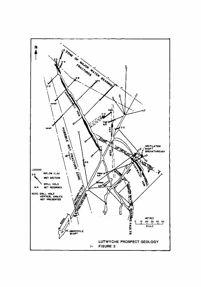
CEMENT GROUTING SURVEY81 PENETRATION RATE WATER INFLOWS m i n u t e s pe r r ~ l ( I - 5 ~ m L / I
0 20 40 SO II10 100 IZO [40 I 2
LEGEND: - F~ I GROUT DUMP ZONE
BOTTOM DEPTH NOT K N O ~
ver t . VERT ICAL
inc. SLIGHTLY OFF VERTICAL
O-75 ~ OFF VERTICAL
LUTWYCHE PROSPECT
VENTILATION SHAFT PILOT HOLE RECORD
FIGURE 3 28

TABLE 1 GROUTING AT 340m
NO. OPERATION TIME HR~
i Drill 6m past water intersection 3.3
2 Trip out rods and bit 25.2
3 Remove Blooie can 1.O
4 Remove bit sub 0.5
5 Lay rig back 1.O
6 Trip in grouting rods 6.2
7 Set packer and pressure test 0.5
8 Mix cement and additive 1.8
9 Pump grout 1.5
lO Trip out grouting rods 5.2
ll Check and clean packer 0.8
12 Stand rig up 0.5
13 Fit bit 0.2
l~ Fit Blooie can and bit 1.0
15 Trip in rods and bit 22.7
16 Drill out 6m cement 1.O
17 Recommence drilling
Total Grout Time 72.4
Operational Experience
Water was first intersected at approximately 85m and exhibited a static level lOm above local creek level at approximately 60m below the surface. Drilling continued to 93.3m before water inflow prevented further drilling. The first grouting operation was undertaken after a "slug test" of the hole to show fracture zone permeability. The grout was later drilled out and an air llft-test showed the operation to have been successful.
Subsequen~ grouting operations were performed as shown in(Figure 3), but the slow operation rate of the raise boring rig and the unreliability of the packer lead tc a modified approach being taken to drilling and grouting.
29

30

: ~','. ! i ! ! n,LJ i i l l I l L ] l l l l
. . . . ' I " . . . . . . . . J i l l L " : : " �9 . . . - I Y r ]
�9 " II11
," Ill l l l l
I ir. i~
I I '
} . : : : : : ] ~ I l I i i i 1 i I l l
. . . 111 . . . . J i l l L . , , ' ' * ~ 1111 L . . .
1 I I I I L . . .
l I I i i
.,... 1[l [I I 0 ) 00 I 000
T IM( (m iml |
F I N A L A I R L I F T P U M P I N G T E S T R E S U L T S
I ~ler ~ischGrQe ~ o i r inle)
'VicfrQui~.......- - ~' ~ I" poly )ui~l
i T M
/ groclf formolion
/ / 103m S.W.L
I ! -- ~ 14~finr W.L.
/ 01 slot1 /
/ Qfllf Dumping Ik-- /--- r
/ mixture / 180m m~
/ t 20Ore- - .
J ~-" airline submergence
/ / levels
L 1" ~ 320m . . . . 330m .-._-._-~& ~ gr~u! -_~_-_-
- 366m ~ 375m breGklhrouoh inlo chClnl~er
AIRLIFT PUMPING TEST ARRANGEMENT
L U T W Y C H E P R O S P E C T
V E N T I L A T I O N S H A F T P I L O T H O L E
F I G U R E 4
31

Firstly the frequency of water inflows was such that in order to maintain drilling continuity, the 6m grouting interval was abandoned in favour of grouting each time the airlifted inflow exceeded 3.SL/s or prevented~drilling on after rod changes (every 3m). Secondly, an 830 kPa 0.3mO/s compressor was brought to site and air relief ports were drilled in the drill pipe couplings at 50m intervals in order to permit grea~er hydrostatic head pressures to be over come after rod changes.
The use of higher pressure air was not possible with the raise boring machine due to pressure limitation on the swivel seals and hydraulic motor seals. Stiff foam drilling was also used to further slow down the rate of water inflow (Plate 1).
A total of 27 downhole grouting operations were undertaken with the grout pumping being continued until a pressure of 480 - 690 kPa was recorded at the surface or until the packer failed. The grout mix involved a type B early strength Portland cement mixed to S.G. = 1.7 with 3% of accellerator/fluidifier added on a weight for weight basis with cement. It proved inefficient and inaffective to mix to a higher S.G. Grouting intervals were overlapped and one finely fractured zone between 290 and 293m, not amenable to cement grouts, was grouted with a silica gel grout. This however was unsuccessul.
Overall, the entire hole section was grouted but some water inflow still occurred when full depth was achieved.
Late stage drilling below 285m was carried out by water flush methods because the rig could not change rods sufficiently rapidly to avoid the build up of hydrostatic head pressure exceeding the applicable pressures to the rig. This meant that the deeper fracture zones to 384m could not be identified by specific depth flow intersection. Pressure grouting using the packer was carried out and tested and found to be sound. Further grouting was carried expecially across the zone 290 - 300m where the finely fractured zone would not accept the Portland cement grout. This later grouting was done by dumping and though it was judged to have been successful, it is probably this zone which gives the inflow recorded on pilot hole completion.
An air lift pumping test was conducted with an eductor pipe as shown in (Figure h) on completion of drilling and in advance of break through. The test was run for 1,060 minutes with the air inductor line being progressively lowered to ensure constant submergence, constant hydraulic efficiency and thereby, constant discharge. The pumping test curve shows the impact of the hole volume in the test results. The pumping test data both for drawdown and recovery were analysed using the techniques of Papadopulos and Cooper (1967). This analysis ind~ated a residual fractured rock trans~issivity to the hole of 0.Sm~/d. Estimating storativity at 1 x 10--, the inflow to the shaft at full diameter was estimated at less than 3.8 L/s. The actual inflow recorded on completion of reaming was 3-75 L/s. This inflow falls within the tolerable limit ~ for the shaft and mine operation.
32

Review of Operation
The initial assessment that water inflows to the proposed ventilation shaft would prove troublesome was entirely confirmed and it is apparent that inflows in the range 12 - 33 L/s would have occurred had not grouting been undertaken. Measurement of air lifted flows in the low discharge range proved difficult due to spray and it was necessary to add an allowance for unrecorded flows.
The fact that no initial investigatory drilling was undertaken at the site to check rock conditions, fracture patterns and water inflow conditions lead to the assumption that the operation would be simple with perhaps a few grouting operations only. It was decided that this would not unduly interrupt the pilot hole drilling operations of the raise boring machine. This proved to be incorrect. The total pilot hole drilling operation took 120 days of which 16 days were drilling and the remainder grouting or delays waiting on equipment or problems associated with water inflow delays.
The raise boring machine proved to be very slow in running and pulling pipe. It operates with 3m rod lengths and it is poorly designed for operating in wet hole conditions where high pressure air is required. Moreover, it is an expensive machine against which a high hire rate applies. Also the slze of the pilot hole necessarily drilled precludes the use of standard grouting tools and results in large stresses being applied to any packer required to operate against high pressures. As a result failures and inconsistancies occur.
Further, the adoption of a constant pressure or constant maximum volume criteria as a basis for cessation of grouting operations, where variable grout section lengths of unknown permeability exists leads to variable grouting pressures being applied. This plus the need to overlap grouting operations and to regrout certain sections resulted in inconsistant pressures being applied during grouting. The interconnected nature of the fracture pattern caused transference of pressure, from one zone to another during grouting and hence failures of previously grouted of sections were recorded.
Finally, the finely fractured nature of the zone between 290 and 293m proved incapable of pressure grouting with Portland cement from the hole. Had consistant hydraulic characteristic testing been carried out in advance of grouting, or a cored hole been sunk, the differnce in this section would have been identified in advance and the need for a different grout formulation and technique would have bean determined. This may or may not have resulted in this zone being successfully plugged.
With the benefit of hindsight a fully cored diamond drill hole or a 125mm air drilled hole would have identified the problem zones in the sequence in advance and permitted them to be evaluated and perhaps fully grouted using standard techniques and tools at low cost. In addition, the attitude of the fracture zone �9 may have been identifiable and the cost of grouting more closely evaluated in advance. Such information could have resulted in a different site being selected for the shaft.
33

The result of their being 27 grouting operations necessary rather three as was originally estimated caused in increase in the cost of this e~ement of the project by a factor of 9.6. Problems with equipment and the time involved in grouting caused other cast elements to rise by a factor of 2.4 and the overall contract to escalate by a factor of 1.5. The drilling and grouting of a preliminary fully cored investigation hole or air drilled 125mm hole could have been accommodated in the cost overrun with the cost being between 60 and 70~ of the overrun.
Grout penetration was, with one exception, easily achieved to a depth which has proved satisfactory for the shaft diameter. The only problem with drilling and grouting in advance was the possibility of slim holes drifting off alignment resulting in the raise bore pilot hole and shaft intersecting in part a different and perhaps ungrouted sequence.
This problem could be overcome by taking considerable care in controlling the direction of the slim investigatory bole and, since cement is softer than the formation, using this bole as the pilot for the raise bore pilot hole. The alignment of the pilot hole drilled for the ventilation shaft was checked by Camera survey every 3Om throughout its length but was still reported to be 9.1m off target at the bottom.
CONCLUSION
Water inflow into ventilation shafts is seen to be major potential problem which deseryes seriou~ consideration at the time of shaft site selection, designing the shaft and selecting ventilation equipment. Thorou~- investigation is warranted in advance of construction to ensure that 1~he construction techniques, grouting techniques and grout formulations selected are capable of being efficiently applied and effective in the hydrogeologicalenvlronment applying at the site. Failure to do this can result in serious diminution of ventilation shaft efficiency, significant operating cost penalties, construction cost over-runs or, in the worst case, water inflows exceeding the installed pumping capacity of the workings for which the shaft is being constructed~
In the case presented in this paper, the grouting operations were largely successful; but the unpredicted grouting problems and water problems incurred a cost overrun of approximately tAIO0,O00. However, a fully cored and pressure grouted directionally controlled diamond drill hole, on an air hammer drilled hole would have cost between $A60,000 and 70,000, hence the actual cost overrun was about 20~ on the total contract. This does not however include the costs incurred in time delays, which were very considerable, and represents a potential cost in lost production of much higher order. This would have been reduced or perhaps elemlnated had a test hole preceeded the shaft ~rilling operation.
The authors experience of this and similar projects in Australia have indicated that water problems around raise bored shafts are frequently inadequately recognized in advance and that these problems have proven expensive to resolve. It is also apparent that a greater range of grouting fluid is desirable if all water inflow environments
are tO be adequately sealed.
34

REFERENCES
Australian Groundwater Consultants Pry Lid (1978) Lutwyche ProJer Groundwater Problems - Unpub. Rep. for Aberfoyle Mining Ltd.
Papadopulos I.S. and Cooper H.H. Jr. (1967) 'Drawdown in a well of large diameter. Water Resources Research, Vol 3 No i p p 241 - 2~4.
Reynolds P.J. & A.J. Titley (1979) The Lutwyche Ventilation Project. Unpub. Rep. by Aberforyle Tin Ltd.
$5