Embed Size (px)
Citation preview
www.ventexinc .com August 2013
• Architectural Blade Louvers
• Drainable Blade Louvers
• Wind-Driven Rain Louvers
• Sightproof Louvers
• Acoustical Louvers
• Thinline Louvers
• Operable Louvers
• Penthouses
• Backdraft Dampers
• Gravity Ventilators
• Wall Hoods
Archives of Ontario Building, York University, Toronto, Ontario
LOUVER PRODUCTSLOUVER PRODUCTS
MODEL SELECTION GUIDE . . . . . . . . . . . . . . . . . . . . . . . . . . . . . . . . . . . . . . . . . . . . . . . . . . . . . . . .3
LOUVER SIZING GUIDELINES & ACCESSORIES . . . . . . . . . . . . . . . . . . . . . . . . . . . . . . . . . . . . . . . . .4
AVAILABLE FINISHES . . . . . . . . . . . . . . . . . . . . . . . . . . . . . . . . . . . . . . . . . . . . . . . . . . . . . . . . . . . . .5
MODEL 2210/2215 EXHAUST LOUVERS . . . . . . . . . . . . . . . . . . . . . . . . . . . . . . . . . . . . . . . . . . . . . .6
MODEL 2220/2225 STORMPROOF LOUVERS . . . . . . . . . . . . . . . . . . . . . . . . . . . . . . . . . . . . . . . . .7
MODEL 2410/2415 HI PRO EXHAUST LOUVERS . . . . . . . . . . . . . . . . . . . . . . . . . . . . . . . . . . . . . . .8
MODEL 2450/2455 HI PRO HIGH PERFORMANCE LOUVERS . . . . . . . . . . . . . . . . . . . . . . . . . . . . .9
MODEL 2420/2425 HI PRO STORMPROOF LOUVERS . . . . . . . . . . . . . . . . . . . . . . . . . . . . . . . . . .10
MODEL 2430/2435 HI PRO DRAINABLE LOUVERS . . . . . . . . . . . . . . . . . . . . . . . . . . . . . . . . . . . . .12
MODEL 2440/2445 TRANSFORMER VAULT LOUVERS . . . . . . . . . . . . . . . . . . . . . . . . . . . . . . . . . .14
MODEL 2590 WIND-DRIVEN RAIN LOUVER . . . . . . . . . . . . . . . . . . . . . . . . . . . . . . . . . . . . . . . . . .15
MODEL 2620/2625 STORMPROOF LOUVERS . . . . . . . . . . . . . . . . . . . . . . . . . . . . . . . . . . . . . . . .16
MODEL 2630/2635 DRAINABLE LOUVERS . . . . . . . . . . . . . . . . . . . . . . . . . . . . . . . . . . . . . . . . . . .18
MITRE CORNER PENTHOUSE . . . . . . . . . . . . . . . . . . . . . . . . . . . . . . . . . . . . . . . . . . . . . . . . . . . . . .20
MULLION CORNER PENTHOUSE . . . . . . . . . . . . . . . . . . . . . . . . . . . . . . . . . . . . . . . . . . . . . . . . . . .21
MODELS GV-I & GV-E GRAVITY VENTILATORS . . . . . . . . . . . . . . . . . . . . . . . . . . . . . . . . . . . . . . . .22
MODELS WHD-45 & WHD-90 WEATHER HOODS . . . . . . . . . . . . . . . . . . . . . . . . . . . . . . . . . . . . .23
MODEL SERIES ACL ACOUSTIC LOUVERS . . . . . . . . . . . . . . . . . . . . . . . . . . . . . . . . . . . . . . . . . . .24
MODEL BV – BRICK VENT . . . . . . . . . . . . . . . . . . . . . . . . . . . . . . . . . . . . . . . . . . . . . . . . . . . . . . . .26
MODEL 2420-OP/2425-OP STORMPROOF OPERABLE LOUVER . . . . . . . . . . . . . . . . . . . . . . . . . .27
MODEL 1200 EXTRUDED BACKDRAFT DAMPER (FORMERLY BDD) . . . . . . . . . . . . . . . . . . . . . . .28
MODEL 1100 ROLL-FORMED BLADE BACKDRAFT DAMPER (FORMERLY RFD) . . . . . . . . . . . . . .30
MODEL 1300 MOTORIZED DAMPER (FORMERLY MBD) . . . . . . . . . . . . . . . . . . . . . . . . . . . . . . . .31
2 www.ventexinc.com • Phone 905.857.4700 • Toll Free Phone: 1.800.668.7214
TABLE OF CONTENTS
NOTE:Although great care has been taken in the production of this catalogue, illustrative or copy errors may occur.Ventex assumes no liability for any errors contained herein. This publication supercedes all prior technical, policy, and print data.Specifications subject to change without notice. Visit www.ventexinc.com for the most current information.Copyright © August 2013 Ventex. ALL RIGHTS RESERVED. Printed in Canada.
Cover photo: Ventex Model 2420 Louvers, Archives of Ontario Building, York University, Toronto, ON
Fax: 905.857.4730 • Toll Free Fax: 1.888.891.6504 • www.ventexinc.com 3
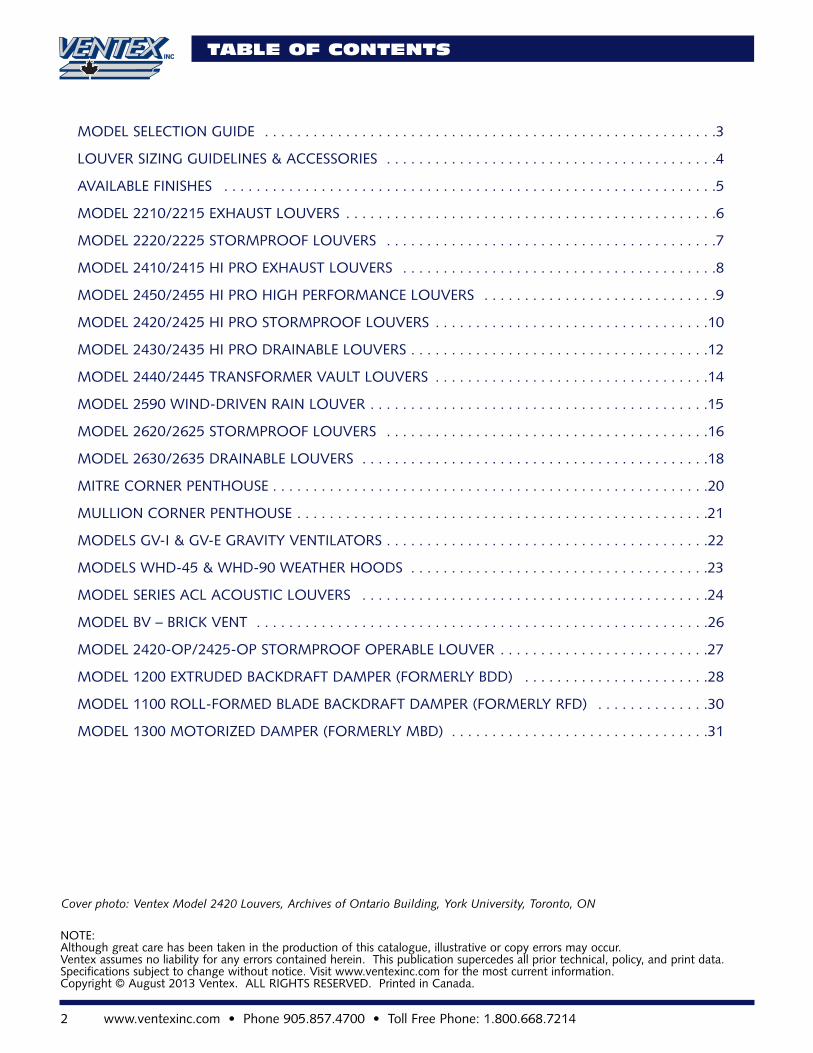
Model Material Thickness Blade Type Blade Centre Min. Maximum Single Maximum DoubleHeight Panel Width Panel Width
1200 Extr. Alum. 0.062” Gravity Blades 3 3/4” 9” 40” 60”
1300 Extr. Alum. 0.062” Motor Control 3 3/4” 8” 40” 60”
1100 Rolled Alum. 0.062” & 0.032” Gravity Blades 3 3/4” 9” 35” 60”
MODEL SELECTION GUIDE
V E N T E X M O D E L S E L E C T I O N G U I D E
Depth Model Material Blade Blade Blade Blade Min. Max. Panel Max. Panel Free AreaThickness Type Angle Centre Height Width Size Unit Size
48” x 48”
2” 2220/2225 Extr. Alum.* 0.062” Stormproof 45° 3” 6” 72” 48 sq. ft. 7.01 sq. ft.
2” 2210/2215 Extr. Alum.* 0.062” Straight 30° 2” 6” 72” 48 sq. ft. 8.51 sq. ft.
4” 2420/2425 Extr. Alum.* 0.081” Stormproof 45° 4 7/8” 12” 120” 60 sq. ft. 8.00 sq. ft.
4” 2430/2435 Extr. Alum.* 0.081” Drainable 35° 3 1/2” 12” 120” 60 sq. ft. 9.06 sq. ft.
4” 2410/2415 Extr. Alum.* 0.081” Straight 35° 3 1/2” 12” 120” 60 sq. ft. 8.92 sq. ft.
4” 2440/2445 Extr. Alum.* 0.062” Chevron 45° 3” 12” 72” 48 sq. ft. 7.22 sq. ft.
4” 2420-OP Extr. Alum. 0.081” Operable 45° 6 1/8” 16” 60” 24 sq. ft. 6.83 sq. ft.2425-OP
4” 2450/2455 Extr. Alum.* 0.081” Straight 35° 3 1/2” 12” 120” 60 sq. ft. 8.92 sq. ft.
4” 2460/2465 Extr. Alum.* 0.081” Stormproof 45° 4 7/8” 12” 120” 60 sq. ft. 8.00 sq. ft.
5” 2590 Extr. Alum. 0.065” Wind/Rain 40° 2.75” 12” 60” 60 sq. ft 7.51 sq. ft
6” 2620/2625 Extr. Alum.* 0.081” Stormproof 45° 7 1/4” 16” 72” 72 sq. ft. 8.06 sq. ft.
6” 2630/2635 Extr. Alum.* 0.081” Drainable 40° 4 5/8” 16” 72” 72 sq. ft. 8.30 sq. ft.
6” 2670-CLD Extr. Alum. 0.081” Combination 40° 3.75” 12” 60” 30 sq. ft 8.00 sq. ft
EXTRUDED ALUMINUM LOUVERS
ACOUSTIC LOUVERS
DAMPERS
Depth Model Material Blade Blade Blade Blade Min. Max. Panel Max. Panel Free AreaThickness Type Angle Centre Height Width Size Unit Size
48” x 48”6” ACL600 Extr. Alum.* 0.090” Acoustic 45° 6” 16” 60” 50 sq. ft. 4.40 sq. ft.
Stormproof6” ACL600F Formed 0.063” Acoustic 45° 6” 16” 60” 50 sq. ft. 6.01 sq. ft.
Alum.* Airfoil8” ACL800 Formed 0.063” Acoustic 45° 8” 16” 60” 50 sq. ft. 4.24 sq. ft.
Alum.* Straight8” ACL800F Formed 0.063” Acoustic 45° 8” 16” 60” 50 sq. ft. 5.21 sq. ft.
Alum.* Airfoil12” ACL1200 Formed 0.063” Acoustic 45° 12” 24” 60” 50 sq. ft. 3.94 sq. ft.
Alum.* Straight12” ACL1200F Formed 0.063” Acoustic 45° 12” 24” 60” 50 sq. ft. 5.10 sq. ft.
Alum.* Airfoil12” ACL1200V Formed 0.063” Acoustic 45° 12” 24” 60” 50 sq. ft. 5.41 sq. ft.
Alum.* Chevron
* Available in formed steel and stainless steel construction.
* Available in formed steel and stainless steel construction.
4 www.ventexinc.com • Phone 905.857.4700 • Toll Free Phone: 1.800.668.7214
LOUVER SIZING GUIDELINES & ACCESSORIES
Free area is the unobstructed area of alouver through which air can passfreely. The free area of a louver is oneof the most important considerationswhen sizing a louver. The free areaand total volume of air will determinethe velocity of air through the louver.The free area velocity determines thesize of the louver based on designconstraints such as static pressure dropand water penetration.
The free area of a louver is calculatedby the following formula:Free Area (In sq. ft.) = MD [A+B+(NxC)]/144Where:MD = Minimum distance between thelouver jambs.A = Distance between the head andthe top louver blade.B = Distance between the sill and thebottom louver blade.N = Number of openings between thelouver blades.C = Minimum space between the louverblades.
Percentage Free Area: MD [A+B+(NxC)]/WxHWhere:W = Actual louver width.H = Actual louver height.
SIZING LOUVERS
To choose the correct size louver,please use the following steps:• Determine which louver would be
best suited for the application.• Determine the total volume of air
(Cubic Feet per Minute or CFM) that will pass through the louver.
• Determine the most important design criteria, by choosing from a, b or c:a) Not to allow water to penetrate through the louver. If water pene-tration is the most important designcriteria, then use a velocity less thanthat shown on the water penetrationchart.
b) Not to exceed a certain static pressure drop. If static pressure drop is the most important design criteria, then use a velocityequal to that shown on the pressuredrop chart.c) If both are equally important, use the lower of the two velocities.
• To determine the total free area required, divide the volume of air (CFM) by the velocity through the free area (FPM) .
• Match the free area required to the free area chart of the chosen louver.This will determine the overall dimensions of the louver required.
For example: A louver must allow9300 CFM to pass through it withoutany water penetration and the plancalls for a 4” stormproof louver. Fromthe water penetration chart of model2420, the velocity should be 600 FPM.As a result, the free area required is15.5 sq. ft. and the louver size can befound using the free area chart as64” x 64”.
DRAINABLE LOUVERS
Drainable louvers are designed to collectthe water that flows down over thelouver’s face and disperse the waterthrough spouts in the jambs of thelouver. Drainable louvers are effectiveonly when the blades and drainagespouts are free of debris. They shouldbe checked regularly and cleanedwhen necessary, to ensure they continueto perform well. Drainable louversshould NOT be specified as continuousline louvers. The design of the louversystem requires that the collectedwater be dispersed away from the faceof the louver. By eliminating the visiblemullions on a large span of drainablelouvers, the water could possibly over-flow the gutters and cascade down theface of the louver and fail. Ventexrecommends using drainable louversonly in applications where the louversize is restricted, or there is a large vol-ume of air passing through the louver.
AVAILABLE ACCESSORIES
• 1/2” x 1/2” inter-crimped 14 gauge (.063”) aluminum birdscreen.
• 1/4” x 1/4” inter-crimped 14 gauge (.063”) aluminum bird- screen.
• Insect screen 16” x 18” aluminum mesh.
• 1/2” x 1/2” galvanized birdscreen in a removable frame.
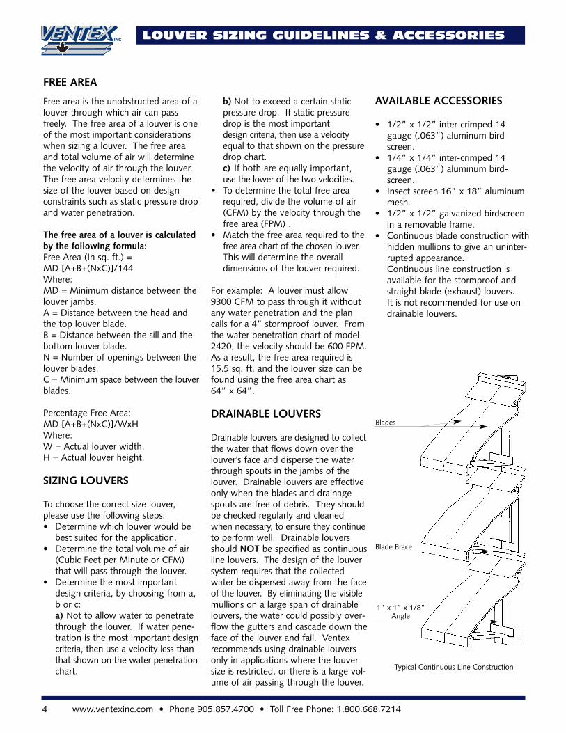
• Continuous blade construction withhidden mullions to give an uninter-rupted appearance.Continuous line construction is available for the stormproof and straight blade (exhaust) louvers. It is not recommended for use on drainable louvers.
Typical Continuous Line Construction
1” x 1” x 1/8”Angle
Blade Brace
Blades
FREE AREA
equipment behind the louver. The louver door may be built into the louver so that the door is hiddenfrom view.
• Ventex manufactures louvers in many custom geometric shapes. Please refer to the specialty geo-metric shapes submittal drawing forsamples of available shapes.
• 1/2” diameter steel bars mounted on 6” centres are available painted or primed for painting by others. The steel frames are 2” deep by 1/4” thick.
• Custom sill lengths and shapes are available. Depth of sill will vary by louver selection.
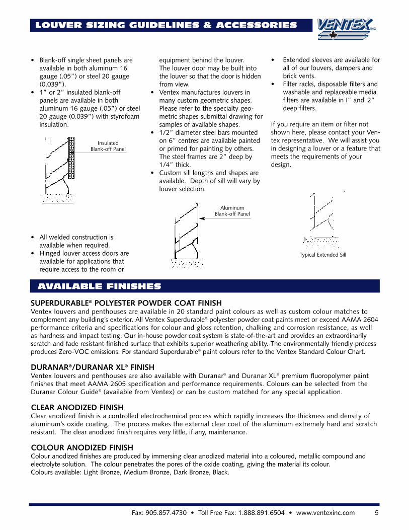
• Blank-off single sheet panels are available in both aluminum 16 gauge (.05”) or steel 20 gauge (0.039”).
• 1” or 2” insulated blank-off panels are available in both aluminum 16 gauge (.05”) or steel20 gauge (0.039”) with styrofoaminsulation.
• All welded construction is available when required.
• Hinged louver access doors are available for applications that require access to the room or
InsulatedBlank-off Panel
Fax: 905.857.4730 • Toll Free Fax: 1.888.891.6504 • www.ventexinc.com 5
AluminumBlank-off Panel
LOUVER SIZING GUIDELINES & ACCESSORIES
• Extended sleeves are available for all of our louvers, dampers and brick vents.
• Filter racks, disposable filters and washable and replaceable media filters are available in I” and 2” deep filters.
If you require an item or filter notshown here, please contact your Ven-tex representative. We will assist youin designing a louver or a feature thatmeets the requirements of yourdesign.
Typical Extended Sill
AVAILABLE FINISHES
SUPERDURABLE® POLYESTER POWDER COAT FINISHVentex louvers and penthouses are available in 20 standard paint colours as well as custom colour matches tocomplement any building’s exterior. All Ventex Superdurable® polyester powder coat paints meet or exceed AAMA 2604performance criteria and specifications for colour and gloss retention, chalking and corrosion resistance, as wellas hardness and impact testing. Our in-house powder coat system is state-of-the-art and provides an extraordinarilyscratch and fade resistant finished surface that exhibits superior weathering ability. The environmentally friendly processproduces Zero-VOC emissions. For standard Superdurable® paint colours refer to the Ventex Standard Colour Chart.
DURANAR®/DURANAR XL® FINISHVentex louvers and penthouses are also available with Duranar® and Duranar XL® premium fluoropolymer paintfinishes that meet AAMA 2605 specification and performance requirements. Colours can be selected from theDuranar Colour Guide® (available from Ventex) or can be custom matched for any special application.
CLEAR ANODIZED FINISHClear anodized finish is a controlled electrochemical process which rapidly increases the thickness and density ofaluminum’s oxide coating. The process makes the external clear coat of the aluminum extremely hard and scratchresistant. The clear anodized finish requires very little, if any, maintenance.
COLOUR ANODIZED FINISHColour anodized finishes are produced by immersing clear anodized material into a coloured, metallic compound andelectrolyte solution. The colour penetrates the pores of the oxide coating, giving the material its colour.Colours available: Light Bronze, Medium Bronze, Dark Bronze, Black.
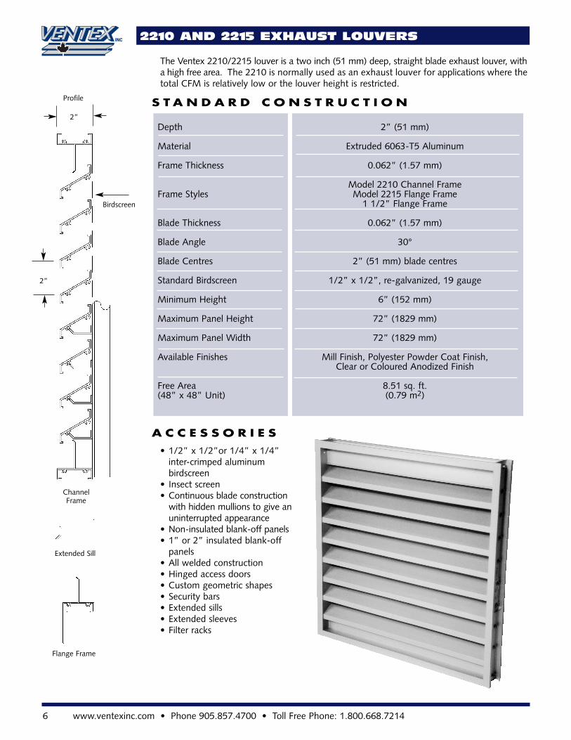
Depth 2” (51 mm)
Material Extruded 6063-T5 Aluminum
Frame Thickness 0.062” (1.57 mm)
Model 2210 Channel Frame Frame Styles Model 2215 Flange Frame
1 1/2” Flange Frame
Blade Thickness 0.062” (1.57 mm)
Blade Angle 30°
Blade Centres 2” (51 mm) blade centres
Standard Birdscreen 1/2” x 1/2”, re-galvanized, 19 gauge
Minimum Height 6” (152 mm)
Maximum Panel Height 72” (1829 mm)
Maximum Panel Width 72” (1829 mm)
Available Finishes Mill Finish, Polyester Powder Coat Finish,Clear or Coloured Anodized Finish
Free Area 8.51 sq. ft.(48” x 48” Unit) (0.79 m2)
6 www.ventexinc.com • Phone 905.857.4700 • Toll Free Phone: 1.800.668.7214
2210 AND 2215 EXHAUST LOUVERS
The Ventex 2210/2215 louver is a two inch (51 mm) deep, straight blade exhaust louver, witha high free area. The 2210 is normally used as an exhaust louver for applications where thetotal CFM is relatively low or the louver height is restricted.
• 1/2” x 1/2”or 1/4” x 1/4” inter-crimped aluminum birdscreen
• Insect screen• Continuous blade construction
with hidden mullions to give anuninterrupted appearance
• Non-insulated blank-off panels• 1” or 2” insulated blank-off
panels• All welded construction• Hinged access doors• Custom geometric shapes• Security bars• Extended sills• Extended sleeves• Filter racks
S T A N D A R D C O N S T R U C T I O N
A C C E S S O R I E S
ChannelFrame
Extended Sill
Flange Frame
2”
Birdscreen
2”
Profile
Fax: 905.857.4730 • Toll Free Fax: 1.888.891.6504 • www.ventexinc.com 7
2220 AND 2225 STORMPROOF LOUVERS
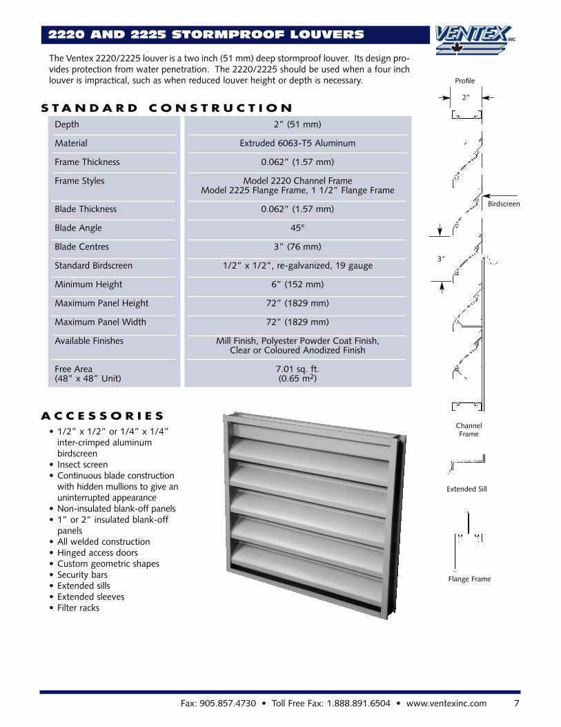
The Ventex 2220/2225 louver is a two inch (51 mm) deep stormproof louver. Its design pro-vides protection from water penetration. The 2220/2225 should be used when a four inchlouver is impractical, such as when reduced louver height or depth is necessary.
S T A N D A R D C O N S T R U C T I O N
A C C E S S O R I E S
Depth 2” (51 mm)
Material Extruded 6063-T5 Aluminum
Frame Thickness 0.062” (1.57 mm)
Frame Styles Model 2220 Channel Frame Model 2225 Flange Frame, 1 1/2” Flange Frame
Blade Thickness 0.062” (1.57 mm)
Blade Angle 45°
Blade Centres 3” (76 mm)
Standard Birdscreen 1/2” x 1/2”, re-galvanized, 19 gauge
Minimum Height 6” (152 mm)
Maximum Panel Height 72” (1829 mm)
Maximum Panel Width 72” (1829 mm)
Available Finishes Mill Finish, Polyester Powder Coat Finish,Clear or Coloured Anodized Finish
Free Area 7.01 sq. ft.(48” x 48” Unit) (0.65 m2)
• 1/2” x 1/2” or 1/4” x 1/4” inter-crimped aluminum birdscreen
• Insect screen• Continuous blade construction
with hidden mullions to give an uninterrupted appearance
• Non-insulated blank-off panels• 1” or 2” insulated blank-off
panels• All welded construction• Hinged access doors• Custom geometric shapes• Security bars• Extended sills• Extended sleeves• Filter racks
ChannelFrame
Extended Sill
Flange Frame
3”
Birdscreen
2”
Profile
8 www.ventexinc.com • Phone 905.857.4700 • Toll Free Phone: 1.800.668.7214
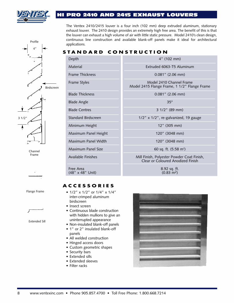
HI PRO 2410 AND 2415 EXHAUST LOUVERS
S T A N D A R D C O N S T R U C T I O N
A C C E S S O R I E S
Depth 4” (102 mm)
Material Extruded 6063-T5 Aluminum
Frame Thickness 0.081” (2.06 mm)
Frame Styles Model 2410 Channel Frame Model 2415 Flange Frame, 1 1/2” Flange Frame
Blade Thickness 0.081” (2.06 mm)
Blade Angle 35°
Blade Centres 3 1/2” (89 mm)
Standard Birdscreen 1/2” x 1/2”, re-galvanized, 19 gauge
Minimum Height 12” (305 mm)
Maximum Panel Height 120” (3048 mm)
Maximum Panel Width 120” (3048 mm)
Maximum Panel Size 60 sq. ft. (5.58 m2)
Available Finishes Mill Finish, Polyester Powder Coat Finish,Clear or Coloured Anodized Finish
Free Area 8.92 sq. ft.(48” x 48” Unit) (0.83 m2)
ChannelFrame
Extended Sill
Flange Frame
3 1/2”
Birdscreen
4”
Profile
• 1/2” x 1/2” or 1/4” x 1/4” inter-crimped aluminum birdscreen
• Insect screen• Continuous blade construction
with hidden mullions to give anuninterrupted appearance
• Non-insulated blank-off panels• 1” or 2” insulated blank-off
panels• All welded construction• Hinged access doors• Custom geometric shapes• Security bars• Extended sills• Extended sleeves• Filter racks
The Ventex 2410/2415 louver is a four inch (102 mm) deep extruded aluminum, stationaryexhaust louver. The 2410 design provides an extremely high free area. The benefit of this is thatthe louver can exhaust a high volume of air with little static pressure. Model 2410’s clean design,continuous line construction and available blank-off panels make it ideal for architecturalapplications.
Fax: 905.857.4730 • Toll Free Fax: 1.888.891.6504 • www.ventexinc.com 9
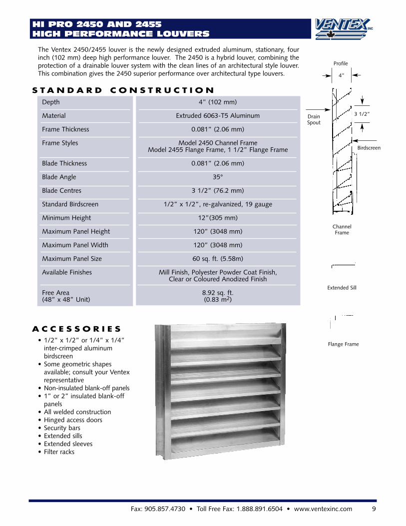
HI PRO 2450 AND 2455 HIGH PERFORMANCE LOUVERS
The Ventex 2450/2455 louver is the newly designed extruded aluminum, stationary, fourinch (102 mm) deep high performance louver. The 2450 is a hybrid louver, combining theprotection of a drainable louver system with the clean lines of an architectural style louver.This combination gives the 2450 superior performance over architectural type louvers.
S T A N D A R D C O N S T R U C T I O N
A C C E S S O R I E S
Depth 4” (102 mm)
Material Extruded 6063-T5 Aluminum
Frame Thickness 0.081” (2.06 mm)
Frame Styles Model 2450 Channel Frame Model 2455 Flange Frame, 1 1/2” Flange Frame
Blade Thickness 0.081” (2.06 mm)
Blade Angle 35°
Blade Centres 3 1/2” (76.2 mm)
Standard Birdscreen 1/2” x 1/2”, re-galvanized, 19 gauge
Minimum Height 12”(305 mm)
Maximum Panel Height 120” (3048 mm)
Maximum Panel Width 120” (3048 mm)
Maximum Panel Size 60 sq. ft. (5.58m)
Available Finishes Mill Finish, Polyester Powder Coat Finish,Clear or Coloured Anodized Finish
Free Area 8.92 sq. ft.(48” x 48” Unit) (0.83 m2)
• 1/2” x 1/2” or 1/4” x 1/4” inter-crimped aluminum birdscreen
• Some geometric shapes available; consult your Ventexrepresentative
• Non-insulated blank-off panels• 1” or 2” insulated blank-off
panels• All welded construction• Hinged access doors• Security bars• Extended sills• Extended sleeves• Filter racks
ChannelFrame
Extended Sill
Flange Frame
Birdscreen
4”
Profile
DrainSpout
3 1/2”
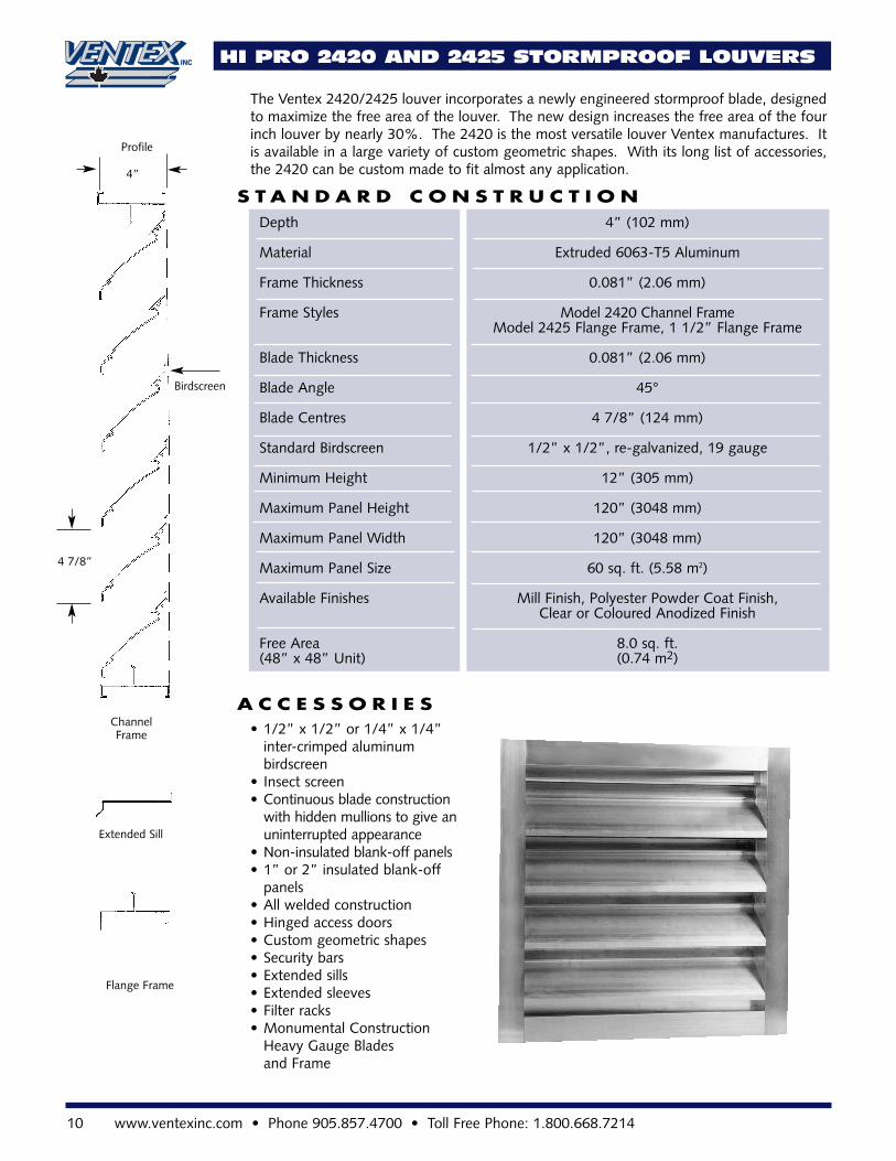
HI PRO 2420 AND 2425 STORMPROOF LOUVERS
The Ventex 2420/2425 louver incorporates a newly engineered stormproof blade, designedto maximize the free area of the louver. The new design increases the free area of the fourinch louver by nearly 30%. The 2420 is the most versatile louver Ventex manufactures. Itis available in a large variety of custom geometric shapes. With its long list of accessories,the 2420 can be custom made to fit almost any application.
S T A N D A R D C O N S T R U C T I O N
A C C E S S O R I E S
Depth 4” (102 mm)
Material Extruded 6063-T5 Aluminum
Frame Thickness 0.081” (2.06 mm)
Frame Styles Model 2420 Channel Frame Model 2425 Flange Frame, 1 1/2” Flange Frame
Blade Thickness 0.081” (2.06 mm)
Blade Angle 45°
Blade Centres 4 7/8” (124 mm)
Standard Birdscreen 1/2” x 1/2”, re-galvanized, 19 gauge
Minimum Height 12” (305 mm)
Maximum Panel Height 120” (3048 mm)
Maximum Panel Width 120” (3048 mm)
Maximum Panel Size 60 sq. ft. (5.58 m2)
Available Finishes Mill Finish, Polyester Powder Coat Finish,Clear or Coloured Anodized Finish
Free Area 8.0 sq. ft.(48” x 48” Unit) (0.74 m2)
ChannelFrame
Extended Sill
Flange Frame
Birdscreen
Profile
• 1/2” x 1/2” or 1/4” x 1/4” inter-crimped aluminum birdscreen
• Insect screen• Continuous blade construction
with hidden mullions to give anuninterrupted appearance
• Non-insulated blank-off panels• 1” or 2” insulated blank-off
panels• All welded construction• Hinged access doors• Custom geometric shapes• Security bars• Extended sills• Extended sleeves• Filter racks• Monumental Construction
Heavy Gauge Blades and Frame
4 7/8”
4”
10 www.ventexinc.com • Phone 905.857.4700 • Toll Free Phone: 1.800.668.7214
RECOMMENDEDSPECIFICATION2420 and 2425
Furnish and install stationary louver models 2420/2425 asmanufactured by Ven-tex Inc, Bolton Ontario. Louvers must belicensed to bear theAMCA seal. Louversshall be 4” (102 mm)deep. Blades shall be0.085” (2.16 mm) andframe shall be 0.085”(2.16 mm) extrudedaluminum, alloy 6063-T5. Louvers shall havea 19 gauge galvanizedbirdscreen.
All materials shall befactory finished afterassembly with PolyesterPowder Coat Paint in acolour selected from theVentex Colour Chart.The louver manufacturershall submit test dataon a 48” x 48” unitshowing that the louverconforms to the dataon this page.
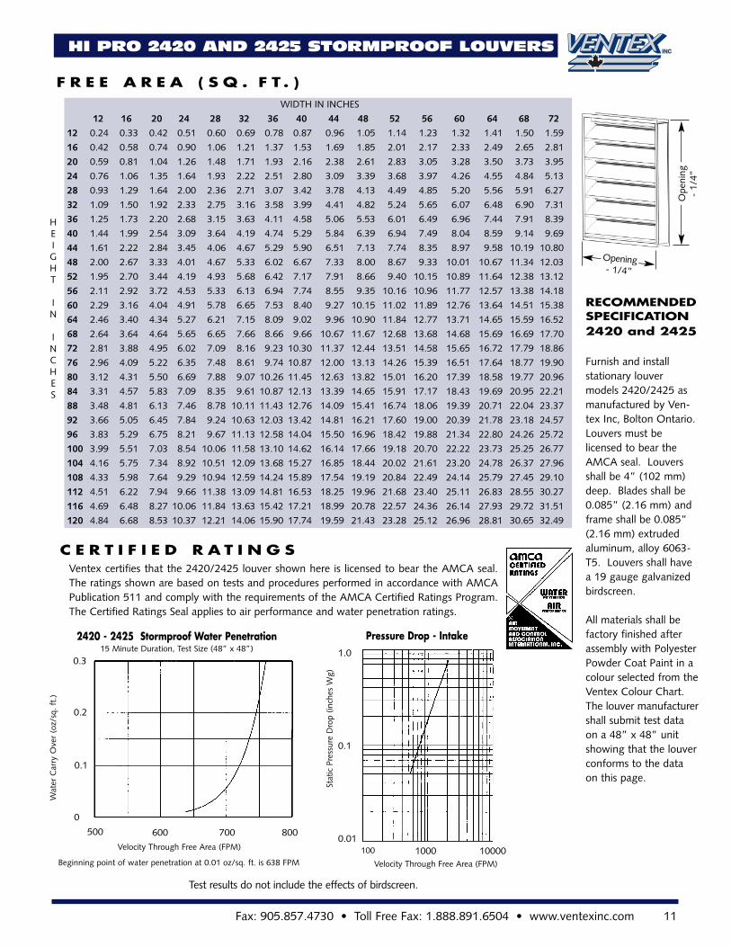
Ventex certifies that the 2420/2425 louver shown here is licensed to bear the AMCA seal.The ratings shown are based on tests and procedures performed in accordance with AMCAPublication 511 and comply with the requirements of the AMCA Certified Ratings Program.The Certified Ratings Seal applies to air performance and water penetration ratings.
F R E E A R E A ( S Q . F T . )
C E R T I F I E D R A T I N G S
HI PRO 2420 AND 2425 STORMPROOF LOUVERS
HEIGHT
IN
INCHES
0.3
800700600500
0
0.1
0.2
Velocity Through Free Area (FPM)
Beginning point of water penetration at 0.01 oz/sq. ft. is 638 FPM
2420 - 2425 Stormproof Water Penetration15 Minute Duration, Test Size (48” x 48”)
Pressure Drop - Intake1.0
0.1
0.01100001000100
Velocity Through Free Area (FPM)
Stat
icPr
essu
reD
rop
(inch
esW
g)
WIDTH IN INCHES
12 16 20 24 28 32 36 40 44 48 52 56 60 64 68 72
12 0.24 0.33 0.42 0.51 0.60 0.69 0.78 0.87 0.96 1.05 1.14 1.23 1.32 1.41 1.50 1.59
16 0.42 0.58 0.74 0.90 1.06 1.21 1.37 1.53 1.69 1.85 2.01 2.17 2.33 2.49 2.65 2.81
20 0.59 0.81 1.04 1.26 1.48 1.71 1.93 2.16 2.38 2.61 2.83 3.05 3.28 3.50 3.73 3.95
24 0.76 1.06 1.35 1.64 1.93 2.22 2.51 2.80 3.09 3.39 3.68 3.97 4.26 4.55 4.84 5.13
28 0.93 1.29 1.64 2.00 2.36 2.71 3.07 3.42 3.78 4.13 4.49 4.85 5.20 5.56 5.91 6.27
32 1.09 1.50 1.92 2.33 2.75 3.16 3.58 3.99 4.41 4.82 5.24 5.65 6.07 6.48 6.90 7.31
36 1.25 1.73 2.20 2.68 3.15 3.63 4.11 4.58 5.06 5.53 6.01 6.49 6.96 7.44 7.91 8.39
40 1.44 1.99 2.54 3.09 3.64 4.19 4.74 5.29 5.84 6.39 6.94 7.49 8.04 8.59 9.14 9.69
44 1.61 2.22 2.84 3.45 4.06 4.67 5.29 5.90 6.51 7.13 7.74 8.35 8.97 9.58 10.19 10.80
48 2.00 2.67 3.33 4.01 4.67 5.33 6.02 6.67 7.33 8.00 8.67 9.33 10.01 10.67 11.34 12.03
52 1.95 2.70 3.44 4.19 4.93 5.68 6.42 7.17 7.91 8.66 9.40 10.15 10.89 11.64 12.38 13.12
56 2.11 2.92 3.72 4.53 5.33 6.13 6.94 7.74 8.55 9.35 10.16 10.96 11.77 12.57 13.38 14.18
60 2.29 3.16 4.04 4.91 5.78 6.65 7.53 8.40 9.27 10.15 11.02 11.89 12.76 13.64 14.51 15.38
64 2.46 3.40 4.34 5.27 6.21 7.15 8.09 9.02 9.96 10.90 11.84 12.77 13.71 14.65 15.59 16.52
68 2.64 3.64 4.64 5.65 6.65 7.66 8.66 9.66 10.67 11.67 12.68 13.68 14.68 15.69 16.69 17.70
72 2.81 3.88 4.95 6.02 7.09 8.16 9.23 10.30 11.37 12.44 13.51 14.58 15.65 16.72 17.79 18.86
76 2.96 4.09 5.22 6.35 7.48 8.61 9.74 10.87 12.00 13.13 14.26 15.39 16.51 17.64 18.77 19.90
80 3.12 4.31 5.50 6.69 7.88 9.07 10.26 11.45 12.63 13.82 15.01 16.20 17.39 18.58 19.77 20.96
84 3.31 4.57 5.83 7.09 8.35 9.61 10.87 12.13 13.39 14.65 15.91 17.17 18.43 19.69 20.95 22.21
88 3.48 4.81 6.13 7.46 8.78 10.11 11.43 12.76 14.09 15.41 16.74 18.06 19.39 20.71 22.04 23.37
92 3.66 5.05 6.45 7.84 9.24 10.63 12.03 13.42 14.81 16.21 17.60 19.00 20.39 21.78 23.18 24.57
96 3.83 5.29 6.75 8.21 9.67 11.13 12.58 14.04 15.50 16.96 18.42 19.88 21.34 22.80 24.26 25.72
100 3.99 5.51 7.03 8.54 10.06 11.58 13.10 14.62 16.14 17.66 19.18 20.70 22.22 23.73 25.25 26.77
104 4.16 5.75 7.34 8.92 10.51 12.09 13.68 15.27 16.85 18.44 20.02 21.61 23.20 24.78 26.37 27.96
108 4.33 5.98 7.64 9.29 10.94 12.59 14.24 15.89 17.54 19.19 20.84 22.49 24.14 25.79 27.45 29.10
112 4.51 6.22 7.94 9.66 11.38 13.09 14.81 16.53 18.25 19.96 21.68 23.40 25.11 26.83 28.55 30.27
116 4.69 6.48 8.27 10.06 11.84 13.63 15.42 17.21 18.99 20.78 22.57 24.36 26.14 27.93 29.72 31.51
120 4.84 6.68 8.53 10.37 12.21 14.06 15.90 17.74 19.59 21.43 23.28 25.12 26.96 28.81 30.65 32.49
Ope
ning
-1/
4”
Opening- 1/4”
Test results do not include the effects of birdscreen.
Wat
erC
arry
Ove
r(o
z/sq
.ft.
)
Fax: 905.857.4730 • Toll Free Fax: 1.888.891.6504 • www.ventexinc.com 11
HI PRO 2430 AND 2435 DRAINABLE LOUVERS
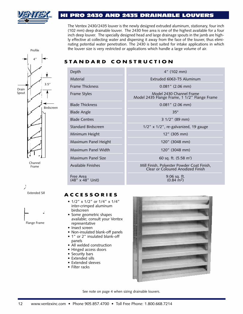
The Ventex 2430/2435 louver is the newly designed extruded aluminum, stationary, four inch(102 mm) deep drainable louver. The 2430 free area is one of the highest available for a fourinch deep louver. The specially designed head and large drainage spouts in the jamb are high-ly effective at collecting water and dispersing it away from the face of the louver, thus elimi-nating potential water penetration. The 2430 is best suited for intake applications in whichthe louver size is very restricted or applications which handle a large volume of air.
S T A N D A R D C O N S T R U C T I O N
A C C E S S O R I E S
Depth 4” (102 mm)
Material Extruded 6063-T5 Aluminum
Frame Thickness 0.081” (2.06 mm)
Frame Styles Model 2430 Channel Frame Model 2435 Flange Frame, 1 1/2” Flange Frame
Blade Thickness 0.081” (2.06 mm)
Blade Angle 35°
Blade Centres 3 1/2” (89 mm)
Standard Birdscreen 1/2” x 1/2”, re-galvanized, 19 gauge
Minimum Height 12” (305 mm)
Maximum Panel Height 120” (3048 mm)
Maximum Panel Width 120” (3048 mm)
Maximum Panel Size 60 sq. ft. (5.58 m2)
Available Finishes Mill Finish, Polyester Powder Coat Finish,Clear or Coloured Anodized Finish
Free Area 9.06 sq. ft.(48” x 48” Unit) (0.84 m2)
ChannelFrame
Extended Sill
Flange Frame
3.5”
Birdscreen
4”
Profile
• 1/2” x 1/2” or 1/4” x 1/4” inter-crimped aluminum birdscreen
• Some geometric shapes available; consult your Ventex representative
• Insect screen• Non-insulated blank-off panels• 1” or 2” insulated blank-off
panels• All welded construction• Hinged access doors• Security bars• Extended sills• Extended sleeves• Filter racks
DrainSpout
12 www.ventexinc.com • Phone 905.857.4700 • Toll Free Phone: 1.800.668.7214
See note on page 4 when sizing drainable louvers.
RECOMMENDED SPECIFICATION2430 and 2435
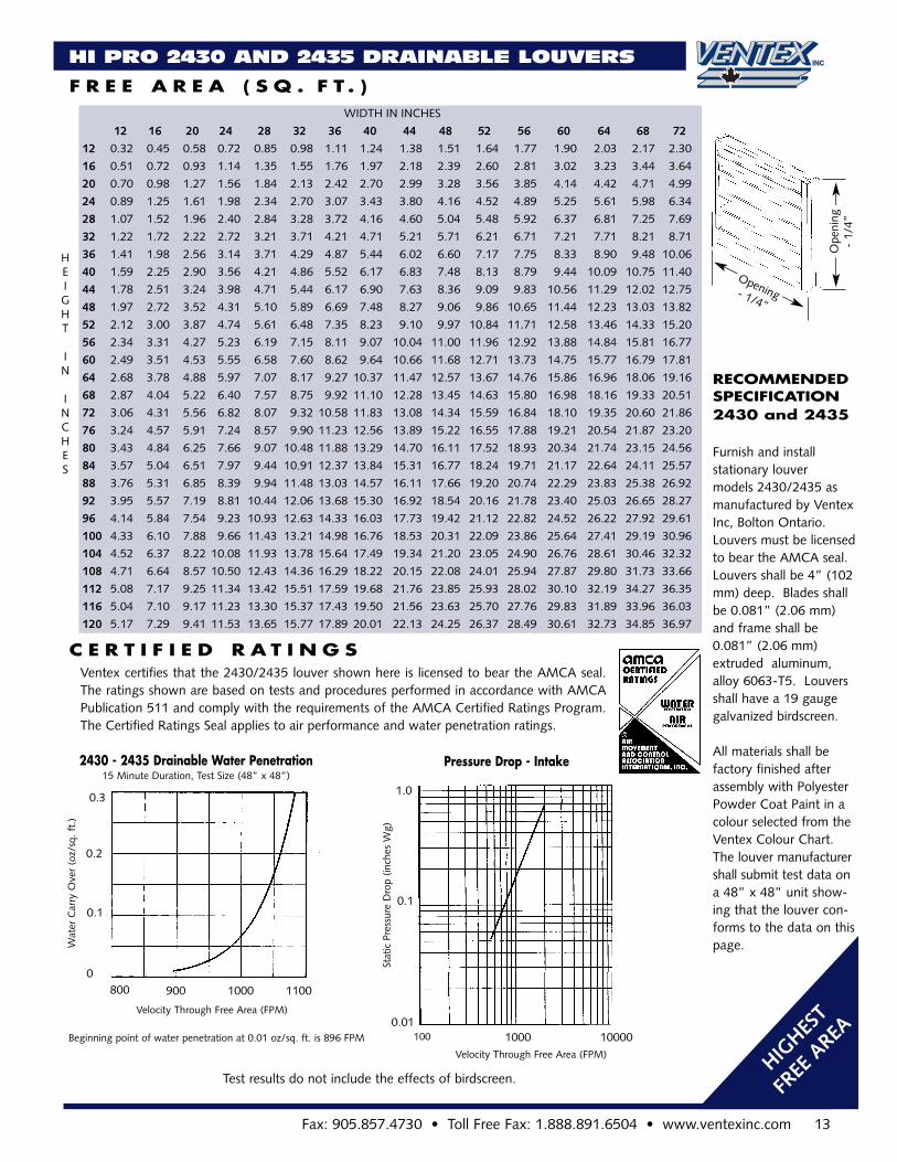
Furnish and install stationary louver models 2430/2435 asmanufactured by VentexInc, Bolton Ontario. Louvers must be licensedto bear the AMCA seal.Louvers shall be 4” (102mm) deep. Blades shallbe 0.081” (2.06 mm)and frame shall be0.081” (2.06 mm)extruded aluminum,alloy 6063-T5. Louversshall have a 19 gaugegalvanized birdscreen.
All materials shall befactory finished afterassembly with PolyesterPowder Coat Paint in acolour selected from theVentex Colour Chart.The louver manufacturershall submit test data ona 48” x 48” unit show-ing that the louver con-forms to the data on thispage.
Ventex certifies that the 2430/2435 louver shown here is licensed to bear the AMCA seal.The ratings shown are based on tests and procedures performed in accordance with AMCAPublication 511 and comply with the requirements of the AMCA Certified Ratings Program.The Certified Ratings Seal applies to air performance and water penetration ratings.
F R E E A R E A ( S Q . F T . )
C E R T I F I E D R A T I N G S
HI PRO 2430 AND 2435 DRAINABLE LOUVERS
HEIGHT
IN
INCHES
110010009008000
0.1
0.2
Velocity Through Free Area (FPM)
Beginning point of water penetration at 0.01 oz/sq. ft. is 896 FPM
2430 - 2435 Drainable Water Penetration15 Minute Duration, Test Size (48” x 48”)
Pressure Drop - Intake
1.0
0.1
0.01100001000100
Velocity Through Free Area (FPM)
Stat
icPr
essu
reD
rop
(inch
esW
g)
WIDTH IN INCHES
12 16 20 24 28 32 36 40 44 48 52 56 60 64 68 72
12 0.32 0.45 0.58 0.72 0.85 0.98 1.11 1.24 1.38 1.51 1.64 1.77 1.90 2.03 2.17 2.30
16 0.51 0.72 0.93 1.14 1.35 1.55 1.76 1.97 2.18 2.39 2.60 2.81 3.02 3.23 3.44 3.64
20 0.70 0.98 1.27 1.56 1.84 2.13 2.42 2.70 2.99 3.28 3.56 3.85 4.14 4.42 4.71 4.99
24 0.89 1.25 1.61 1.98 2.34 2.70 3.07 3.43 3.80 4.16 4.52 4.89 5.25 5.61 5.98 6.34
28 1.07 1.52 1.96 2.40 2.84 3.28 3.72 4.16 4.60 5.04 5.48 5.92 6.37 6.81 7.25 7.69
32 1.22 1.72 2.22 2.72 3.21 3.71 4.21 4.71 5.21 5.71 6.21 6.71 7.21 7.71 8.21 8.71
36 1.41 1.98 2.56 3.14 3.71 4.29 4.87 5.44 6.02 6.60 7.17 7.75 8.33 8.90 9.48 10.06
40 1.59 2.25 2.90 3.56 4.21 4.86 5.52 6.17 6.83 7.48 8.13 8.79 9.44 10.09 10.75 11.40
44 1.78 2.51 3.24 3.98 4.71 5.44 6.17 6.90 7.63 8.36 9.09 9.83 10.56 11.29 12.02 12.75
48 1.97 2.72 3.52 4.31 5.10 5.89 6.69 7.48 8.27 9.06 9.86 10.65 11.44 12.23 13.03 13.82
52 2.12 3.00 3.87 4.74 5.61 6.48 7.35 8.23 9.10 9.97 10.84 11.71 12.58 13.46 14.33 15.20
56 2.34 3.31 4.27 5.23 6.19 7.15 8.11 9.07 10.04 11.00 11.96 12.92 13.88 14.84 15.81 16.77
60 2.49 3.51 4.53 5.55 6.58 7.60 8.62 9.64 10.66 11.68 12.71 13.73 14.75 15.77 16.79 17.81
64 2.68 3.78 4.88 5.97 7.07 8.17 9.27 10.37 11.47 12.57 13.67 14.76 15.86 16.96 18.06 19.16
68 2.87 4.04 5.22 6.40 7.57 8.75 9.92 11.10 12.28 13.45 14.63 15.80 16.98 18.16 19.33 20.51
72 3.06 4.31 5.56 6.82 8.07 9.32 10.58 11.83 13.08 14.34 15.59 16.84 18.10 19.35 20.60 21.86
76 3.24 4.57 5.91 7.24 8.57 9.90 11.23 12.56 13.89 15.22 16.55 17.88 19.21 20.54 21.87 23.20
80 3.43 4.84 6.25 7.66 9.07 10.48 11.88 13.29 14.70 16.11 17.52 18.93 20.34 21.74 23.15 24.56
84 3.57 5.04 6.51 7.97 9.44 10.91 12.37 13.84 15.31 16.77 18.24 19.71 21.17 22.64 24.11 25.57
88 3.76 5.31 6.85 8.39 9.94 11.48 13.03 14.57 16.11 17.66 19.20 20.74 22.29 23.83 25.38 26.92
92 3.95 5.57 7.19 8.81 10.44 12.06 13.68 15.30 16.92 18.54 20.16 21.78 23.40 25.03 26.65 28.27
96 4.14 5.84 7.54 9.23 10.93 12.63 14.33 16.03 17.73 19.42 21.12 22.82 24.52 26.22 27.92 29.61
100 4.33 6.10 7.88 9.66 11.43 13.21 14.98 16.76 18.53 20.31 22.09 23.86 25.64 27.41 29.19 30.96
104 4.52 6.37 8.22 10.08 11.93 13.78 15.64 17.49 19.34 21.20 23.05 24.90 26.76 28.61 30.46 32.32
108 4.71 6.64 8.57 10.50 12.43 14.36 16.29 18.22 20.15 22.08 24.01 25.94 27.87 29.80 31.73 33.66
112 5.08 7.17 9.25 11.34 13.42 15.51 17.59 19.68 21.76 23.85 25.93 28.02 30.10 32.19 34.27 36.35
116 5.04 7.10 9.17 11.23 13.30 15.37 17.43 19.50 21.56 23.63 25.70 27.76 29.83 31.89 33.96 36.03
120 5.17 7.29 9.41 11.53 13.65 15.77 17.89 20.01 22.13 24.25 26.37 28.49 30.61 32.73 34.85 36.97
Ope
ning
-1/
4”
Opening- 1/4”
0.3
Wat
erC
arry
Ove
r(o
z/sq
.ft.
)
Test results do not include the effects of birdscreen.
Fax: 905.857.4730 • Toll Free Fax: 1.888.891.6504 • www.ventexinc.com 13
HIGHES
T
FREE
AREA
14 www.ventexinc.com • Phone 905.857.4700 • Toll Free Phone: 1.800.668.7214
2440 AND 2445 TRANSFORMER VAULT LOUVERS
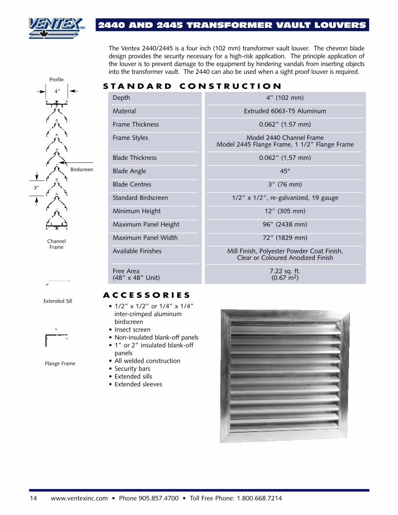
The Ventex 2440/2445 is a four inch (102 mm) transformer vault louver. The chevron bladedesign provides the security necessary for a high-risk application. The principle application ofthe louver is to prevent damage to the equipment by hindering vandals from inserting objectsinto the transformer vault. The 2440 can also be used when a sight proof louver is required.
S T A N D A R D C O N S T R U C T I O N
A C C E S S O R I E S
Depth 4” (102 mm)
Material Extruded 6063-T5 Aluminum
Frame Thickness 0.062” (1.57 mm)
Frame Styles Model 2440 Channel Frame Model 2445 Flange Frame, 1 1/2” Flange Frame
Blade Thickness 0.062” (1.57 mm)
Blade Angle 45°
Blade Centres 3” (76 mm)
Standard Birdscreen 1/2” x 1/2”, re-galvanized, 19 gauge
Minimum Height 12” (305 mm)
Maximum Panel Height 96” (2438 mm)
Maximum Panel Width 72” (1829 mm)
Available Finishes Mill Finish, Polyester Powder Coat Finish,Clear or Coloured Anodized Finish
Free Area 7.22 sq. ft.(48” x 48” Unit) (0.67 m2)
ChannelFrame
Extended Sill
Flange Frame
3”
Birdscreen
4”
Profile
• 1/2” x 1/2” or 1/4” x 1/4” inter-crimped aluminumbirdscreen
• Insect screen• Non-insulated blank-off panels• 1” or 2” insulated blank-off
panels• All welded construction• Security bars• Extended sills• Extended sleeves
Fax: 905.857.4730 • Toll Free Fax: 1.888.891.6504 • www.ventexinc.com 15
MODEL 2590 WIND-DRIVEN RAIN LOUVER
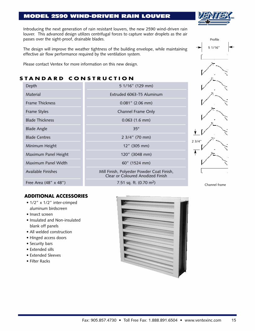
Introducing the next generation of rain resistant louvers, the new 2590 wind-driven rainlouver. This advanced design utilizes centrifugal forces to capture water droplets as the airpasses over the sight-proof, drainable blades.
The design will improve the weather tightness of the building envelope, while maintainingeffective air flow performance required by the ventilation system.
Please contact Ventex for more information on this new design.
S T A N D A R D C O N S T R U C T I O NDepth 5 1/16” (129 mm)
Material Extruded 6063-T5 Aluminum
Frame Thickness 0.081” (2.06 mm)
Frame Styles Channel Frame Only
Blade Thickness 0.063 (1.6 mm)
Blade Angle 35°
Blade Centres 2 3/4” (70 mm)
Minimum Height 12” (305 mm)
Maximum Panel Height 120” (3048 mm)
Maximum Panel Width 60” (1524 mm)
Available Finishes Mill Finish, Polyester Powder Coat Finish,Clear or Coloured Anodized Finish
Free Area (48” x 48”) 7.51 sq. ft. (0.70 m2)
ADDITIONAL ACCESSORIES• 1/2” x 1/2” inter-crimped
aluminum birdscreen• Insect screen• Insulated and Non-insulated
blank off panels• All welded construction• Hinged access doors• Security bars• Extended sills• Extended Sleeves• Filter Racks
2 3/4”
5 1/16”
Profile
Channel frame
16 www.ventexinc.com • Phone 905.857.4700 • Toll Free Phone: 1.800.668.7214
2620 AND 2625 STORMPROOF LOUVERS
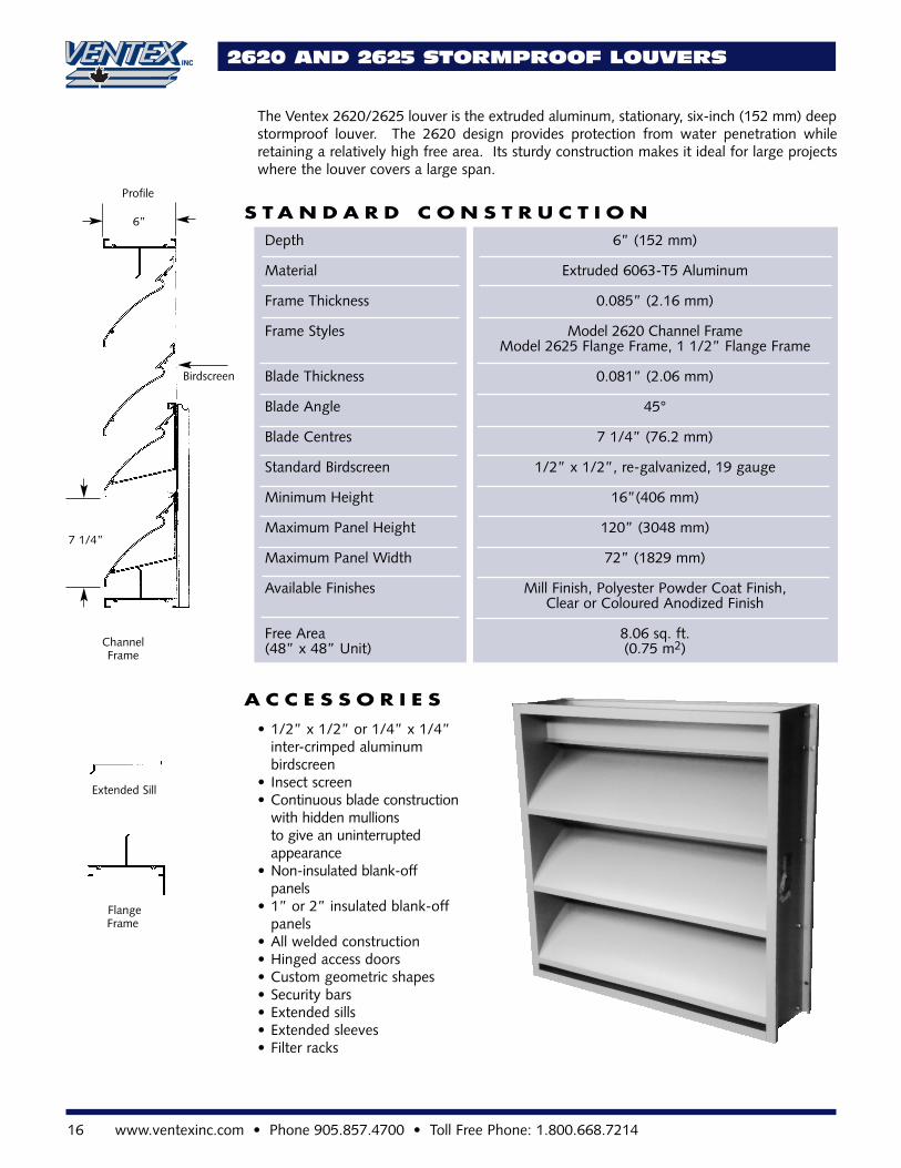
The Ventex 2620/2625 louver is the extruded aluminum, stationary, six-inch (152 mm) deepstormproof louver. The 2620 design provides protection from water penetration whileretaining a relatively high free area. Its sturdy construction makes it ideal for large projectswhere the louver covers a large span.
• 1/2” x 1/2” or 1/4” x 1/4” inter-crimped aluminum birdscreen
• Insect screen• Continuous blade construction
with hidden mullionsto give an uninterrupted appearance
• Non-insulated blank-offpanels
• 1” or 2” insulated blank-off panels
• All welded construction• Hinged access doors• Custom geometric shapes• Security bars• Extended sills• Extended sleeves• Filter racks
S T A N D A R D C O N S T R U C T I O N
A C C E S S O R I E S
ChannelFrame
Extended Sill
FlangeFrame
7 1/4”
Birdscreen
6”
Profile
Depth 6” (152 mm)
Material Extruded 6063-T5 Aluminum
Frame Thickness 0.085” (2.16 mm)
Frame Styles Model 2620 Channel Frame Model 2625 Flange Frame, 1 1/2” Flange Frame
Blade Thickness 0.081” (2.06 mm)
Blade Angle 45°
Blade Centres 7 1/4” (76.2 mm)
Standard Birdscreen 1/2” x 1/2”, re-galvanized, 19 gauge
Minimum Height 16”(406 mm)
Maximum Panel Height 120” (3048 mm)
Maximum Panel Width 72” (1829 mm)
Available Finishes Mill Finish, Polyester Powder Coat Finish,Clear or Coloured Anodized Finish
Free Area 8.06 sq. ft.(48” x 48” Unit) (0.75 m2)
Fax: 905.857.4730 • Toll Free Fax: 1.888.891.6504 • www.ventexinc.com 17
1.0
0.1
0.011000100
Velocity Through Free Area (FPM)
Stat
icPr
essu
reD
rop
(inch
esW
g)
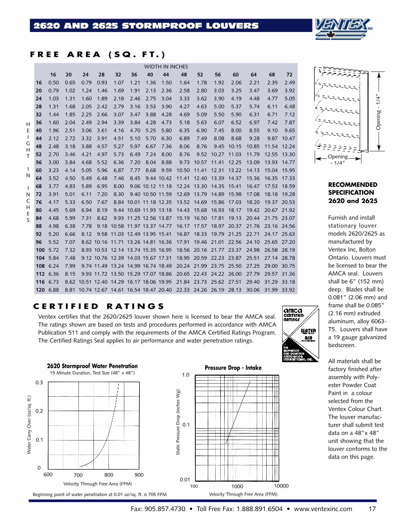
Ventex certifies that the 2620/2625 louver shown here is licensed to bear the AMCA seal.The ratings shown are based on tests and procedures performed in accordance with AMCAPublication 511 and comply with the requirements of the AMCA Certified Ratings Program.The Certified Ratings Seal applies to air performance and water penetration ratings.
C E R T I F I E D R A T I N G S
WIDTH IN INCHES
16 20 24 28 32 36 40 44 48 52 56 60 64 68 72
16 0.50 0.65 0.79 0.93 1.07 1.21 1.36 1.50 1.64 1.78 1.92 2.06 2.21 2.35 2.49
20 0.79 1.02 1.24 1.46 1.69 1.91 2.13 2.36 2.58 2.80 3.03 3.25 3.47 3.69 3.92
24 1.03 1.31 1.60 1.89 2.18 2.46 2.75 3.04 3.33 3.62 3.90 4.19 4.48 4.77 5.05
28 1.31 1.68 2.05 2.42 2.79 3.16 3.53 3.90 4.27 4.63 5.00 5.37 5.74 6.11 6.48
32 1.44 1.85 2.25 2.66 3.07 3.47 3.88 4.28 4.69 5.09 5.50 5.90 6.31 6.71 7.12
36 1.60 2.04 2.49 2.94 3.39 3.84 4.28 4.73 5.18 5.63 6.07 6.52 6.97 7.42 7.87
40 1.96 2.51 3.06 3.61 4.16 4.70 5.25 5.80 6.35 6.90 7.45 8.00 8.55 9.10 9.65
44 2.12 2.72 3.32 3.91 4.51 5.10 5.70 6.30 6.89 7.49 8.08 8.68 9.28 9.87 10.47
48 2.48 3.18 3.88 4.57 5.27 5.97 6.67 7.36 8.06 8.76 9.45 10.15 10.85 11.54 12.24
52 2.70 3.46 4.21 4.97 5.73 6.49 7.24 8.00 8.76 9.52 10.27 11.03 11.79 12.55 13.30
56 3.00 3.84 4.68 5.52 6.36 7.20 8.04 8.88 9.73 10.57 11.41 12.25 13.09 13.93 14.77
60 3.23 4.14 5.05 5.96 6.87 7.77 8.68 9.59 10.50 11.41 12.31 13.22 14.13 15.04 15.95
64 3.52 4.50 5.49 6.48 7.46 8.45 9.44 10.42 11.41 12.40 13.39 14.37 15.36 16.35 17.33
68 3.77 4.83 5.89 6.95 8.00 9.06 10.12 11.18 12.24 13.30 14.35 15.41 16.47 17.53 18.59
72 3.91 5.01 6.11 7.20 8.30 9.40 10.50 11.59 12.69 13.79 14.89 15.98 17.08 18.18 19.28
76 4.17 5.33 6.50 7.67 8.84 10.01 11.18 12.35 13.52 14.69 15.86 17.03 18.20 19.37 20.53
80 4.45 5.69 6.94 8.19 9.44 10.69 11.93 13.18 14.43 15.68 16.93 18.17 19.42 20.67 21.92
84 4.68 5.99 7.31 8.62 9.93 11.25 12.56 13.87 15.19 16.50 17.81 19.13 20.44 21.75 23.07
88 4.98 6.38 7.78 9.18 10.58 11.97 13.37 14.77 16.17 17.57 18.97 20.37 21.76 23.16 24.56
92 5.20 6.66 8.12 9.58 11.03 12.49 13.95 15.41 16.87 18.33 19.79 21.25 22.71 24.17 25.63
96 5.52 7.07 8.62 10.16 11.71 13.26 14.81 16.36 17.91 19.46 21.01 22.56 24.10 25.65 27.20
100 5.72 7.32 8.93 10.53 12.14 13.74 15.35 16.95 18.56 20.16 21.77 23.37 24.98 26.58 28.19
104 5.84 7.48 9.12 10.76 12.39 14.03 15.67 17.31 18.95 20.59 22.23 23.87 25.51 27.14 28.78
108 6.24 7.99 9.74 11.49 13.24 14.99 16.74 18.49 20.24 21.99 23.75 25.50 27.25 29.00 30.75
112 6.36 8.15 9.93 11.72 13.50 15.29 17.07 18.86 20.65 22.43 24.22 26.00 27.79 29.57 31.36
116 6.73 8.62 10.51 12.40 14.29 16.17 18.06 19.95 21.84 23.73 25.62 27.51 29.40 31.29 33.18
120 6.88 8.81 10.74 12.67 14.61 16.54 18.47 20.40 22.33 24.26 26.19 28.13 30.06 31.99 33.92
F R E E A R E A ( S Q . F T . )
2620 AND 2625 STORMPROOF LOUVERS
HEIGHT
IN
INCHES
RECOMMENDEDSPECIFICATION2620 and 2625
Furnish and install stationary louvermodels 2620/2625 asmanufactured by Ventex Inc, BoltonOntario. Louvers mustbe licensed to bear theAMCA seal. Louversshall be 6” (152 mm)deep. Blades shall be0.081” (2.06 mm) andframe shall be 0.085”(2.16 mm) extrudedaluminum, alloy 6063-T5. Louvers shall havea 19 gauge galvanizedbirdscreen.
All materials shall befactory finished afterassembly with Poly-ester Powder CoatPaint in a colourselected from the Ventex Colour Chart.The louver manufac-turer shall submit testdata on a 48”x 48”unit showing that thelouver conforms to thedata on this page.
Ope
ning
-1/
4”
Opening- 1/4”
9008007006000
0.1
0.2
Velocity Through Free Area (FPM)
Beginning point of water penetration at 0.01 oz/sq. ft. is 705 FPM
2620 Stormproof Water Penetration15 Minute Duration, Test Size (48” x 48”)
0.3
Wat
erC
arry
Ove
r(o
z/sq
.ft.
)
10000
Pressure Drop - Intake
18 www.ventexinc.com • Phone 905.857.4700 • Toll Free Phone: 1.800.668.7214
2630 AND 2635 DRAINABLE LOUVERS
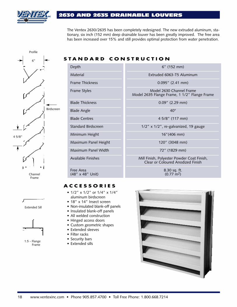
The Ventex 2630/2635 has been completely redesigned. The new extruded aluminum, sta-tionary, six inch (152 mm) deep drainable louver has been greatly improved. The free areahas been increased over 15% and still provides optimal protection from water penetration.
S T A N D A R D C O N S T R U C T I O N
A C C E S S O R I E S
ChannelFrame
Extended Sill
1.5 - FlangeFrame
4 5/8”
Birdscreen
6”
Profile
• 1/2” x 1/2” or 1/4” x 1/4” aluminum birdscreen
• 18” x 14” Insect screen• Non-insulated blank-off panels• Insulated blank-off panels• All welded construction• Hinged access doors• Custom geometric shapes• Extended sleeves• Filter racks• Security bars• Extended sills
Depth 6” (152 mm)
Material Extruded 6063-T5 Aluminum
Frame Thickness 0.095” (2.41 mm)
Frame Styles Model 2630 Channel Frame Model 2635 Flange Frame, 1 1/2” Flange Frame
Blade Thickness 0.09” (2.29 mm)
Blade Angle 40°
Blade Centres 4 5/8” (117 mm)
Standard Birdscreen 1/2” x 1/2”, re-galvanized, 19 gauge
Minimum Height 16”(406 mm)
Maximum Panel Height 120” (3048 mm)
Maximum Panel Width 72” (1829 mm)
Available Finishes Mill Finish, Polyester Powder Coat Finish,Clear or Coloured Anodized Finish
Free Area 8.30 sq. ft.(48” x 48” Unit) (0.77 m2)
Fax: 905.857.4730 • Toll Free Fax: 1.888.891.6504 • www.ventexinc.com 19
RECOMMENDED SPECIFICATION 2630and 2635
Furnish and install stationarylouver models 2630/2635 asmanufactured by Ventex Inc,Bolton Ontario. Louversmust be licensed to bear theAMCA seal. Louvers shall be 6” (152mm) deep. Blades shall be0.090” (2.28 mm) and frameshall be 0.085” (2.16 mm)extruded aluminum, alloy6063-T5. Louvers shall havea 19 gauge galvanized bird-screen.
All materials shall be factoryfinished after assembly withPolyester Powder Coat Paintin a colour selected from theVentex Colour Chart. The louver manufacturer shallsubmit test data on a 48” x48” unit showing that thelouver conforms to the dataon this page.
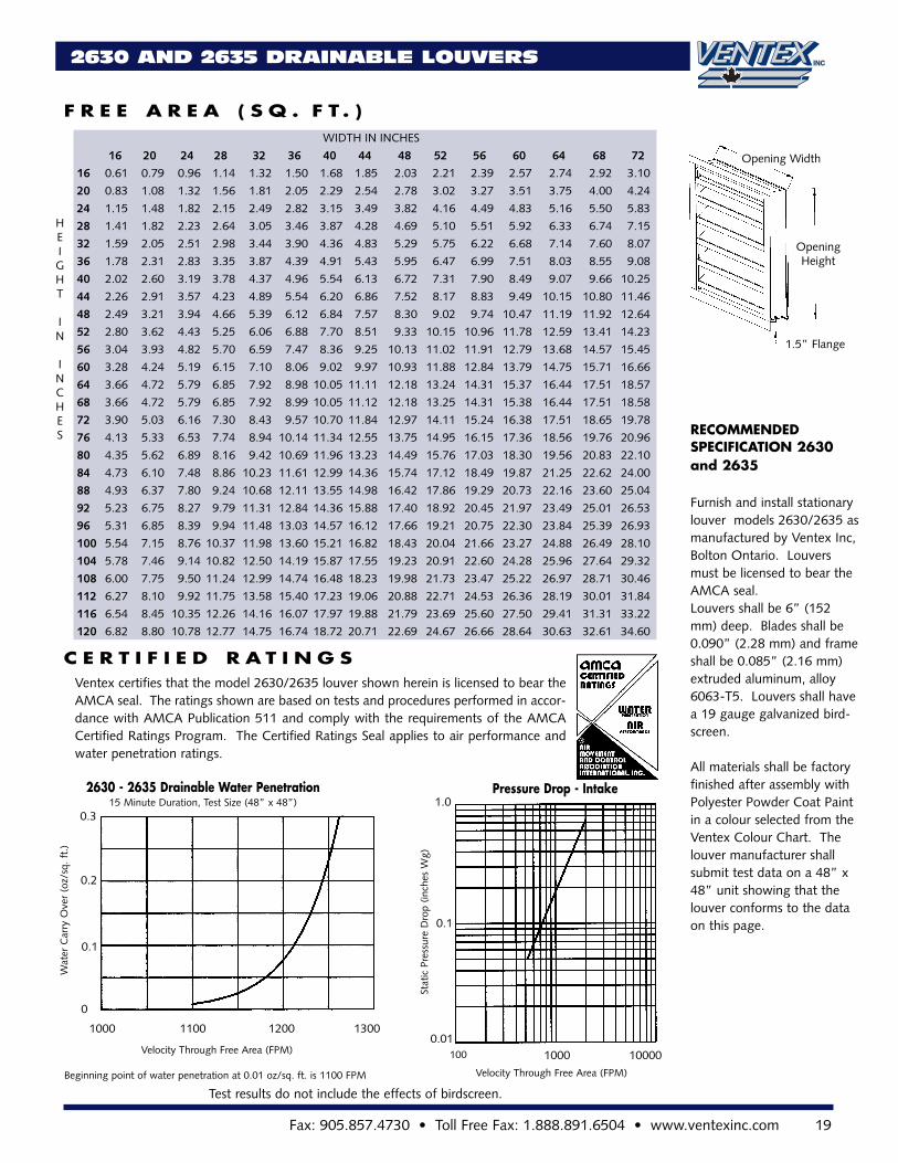
Ventex certifies that the model 2630/2635 louver shown herein is licensed to bear theAMCA seal. The ratings shown are based on tests and procedures performed in accor-dance with AMCA Publication 511 and comply with the requirements of the AMCACertified Ratings Program. The Certified Ratings Seal applies to air performance andwater penetration ratings.
F R E E A R E A ( S Q . F T . )
C E R T I F I E D R A T I N G S
2630 AND 2635 DRAINABLE LOUVERS
HEIGHT
IN
INCHES
0.3
130011001000
0
0.1
0.2
Velocity Through Free Area (FPM)
Beginning point of water penetration at 0.01 oz/sq. ft. is 1100 FPM
2630 - 2635 Drainable Water Penetration15 Minute Duration, Test Size (48” x 48”) 1.0
0.1
0.01100001000100
Velocity Through Free Area (FPM)
Stat
icPr
essu
reD
rop
(inch
esW
g)
WIDTH IN INCHES
16 20 24 28 32 36 40 44 48 52 56 60 64 68 72
16 0.61 0.79 0.96 1.14 1.32 1.50 1.68 1.85 2.03 2.21 2.39 2.57 2.74 2.92 3.10
20 0.83 1.08 1.32 1.56 1.81 2.05 2.29 2.54 2.78 3.02 3.27 3.51 3.75 4.00 4.24
24 1.15 1.48 1.82 2.15 2.49 2.82 3.15 3.49 3.82 4.16 4.49 4.83 5.16 5.50 5.83
28 1.41 1.82 2.23 2.64 3.05 3.46 3.87 4.28 4.69 5.10 5.51 5.92 6.33 6.74 7.15
32 1.59 2.05 2.51 2.98 3.44 3.90 4.36 4.83 5.29 5.75 6.22 6.68 7.14 7.60 8.07
36 1.78 2.31 2.83 3.35 3.87 4.39 4.91 5.43 5.95 6.47 6.99 7.51 8.03 8.55 9.08
40 2.02 2.60 3.19 3.78 4.37 4.96 5.54 6.13 6.72 7.31 7.90 8.49 9.07 9.66 10.25
44 2.26 2.91 3.57 4.23 4.89 5.54 6.20 6.86 7.52 8.17 8.83 9.49 10.15 10.80 11.46
48 2.49 3.21 3.94 4.66 5.39 6.12 6.84 7.57 8.30 9.02 9.74 10.47 11.19 11.92 12.64
52 2.80 3.62 4.43 5.25 6.06 6.88 7.70 8.51 9.33 10.15 10.96 11.78 12.59 13.41 14.23
56 3.04 3.93 4.82 5.70 6.59 7.47 8.36 9.25 10.13 11.02 11.91 12.79 13.68 14.57 15.45
60 3.28 4.24 5.19 6.15 7.10 8.06 9.02 9.97 10.93 11.88 12.84 13.79 14.75 15.71 16.66
64 3.66 4.72 5.79 6.85 7.92 8.98 10.05 11.11 12.18 13.24 14.31 15.37 16.44 17.51 18.57
68 3.66 4.72 5.79 6.85 7.92 8.99 10.05 11.12 12.18 13.25 14.31 15.38 16.44 17.51 18.58
72 3.90 5.03 6.16 7.30 8.43 9.57 10.70 11.84 12.97 14.11 15.24 16.38 17.51 18.65 19.78
76 4.13 5.33 6.53 7.74 8.94 10.14 11.34 12.55 13.75 14.95 16.15 17.36 18.56 19.76 20.96
80 4.35 5.62 6.89 8.16 9.42 10.69 11.96 13.23 14.49 15.76 17.03 18.30 19.56 20.83 22.10
84 4.73 6.10 7.48 8.86 10.23 11.61 12.99 14.36 15.74 17.12 18.49 19.87 21.25 22.62 24.00
88 4.93 6.37 7.80 9.24 10.68 12.11 13.55 14.98 16.42 17.86 19.29 20.73 22.16 23.60 25.04
92 5.23 6.75 8.27 9.79 11.31 12.84 14.36 15.88 17.40 18.92 20.45 21.97 23.49 25.01 26.53
96 5.31 6.85 8.39 9.94 11.48 13.03 14.57 16.12 17.66 19.21 20.75 22.30 23.84 25.39 26.93
100 5.54 7.15 8.76 10.37 11.98 13.60 15.21 16.82 18.43 20.04 21.66 23.27 24.88 26.49 28.10
104 5.78 7.46 9.14 10.82 12.50 14.19 15.87 17.55 19.23 20.91 22.60 24.28 25.96 27.64 29.32
108 6.00 7.75 9.50 11.24 12.99 14.74 16.48 18.23 19.98 21.73 23.47 25.22 26.97 28.71 30.46
112 6.27 8.10 9.92 11.75 13.58 15.40 17.23 19.06 20.88 22.71 24.53 26.36 28.19 30.01 31.84
116 6.54 8.45 10.35 12.26 14.16 16.07 17.97 19.88 21.79 23.69 25.60 27.50 29.41 31.31 33.22
120 6.82 8.80 10.78 12.77 14.75 16.74 18.72 20.71 22.69 24.67 26.66 28.64 30.63 32.61 34.60
OpeningHeight
Wat
erC
arry
Ove
r(o
z/sq
.ft.
)
1200
Test results do not include the effects of birdscreen.
1.5” Flange
Opening Width
Pressure Drop - Intake
20 www.ventexinc.com • Phone 905.857.4700 • Toll Free Phone: 1.800.668.7214
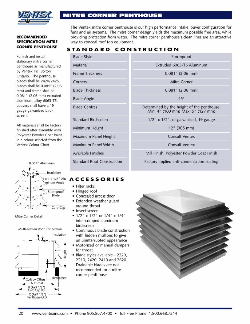
MITRE CORNER PENTHOUSE
The Ventex mitre corner penthouse is our high performance intake louver configuration forfans and air systems. The mitre corner design yields the maximum possible free area, whileproviding protection from water. The mitre corner penthouse’s clean lines are an attractiveway to conceal roof top equipment.
S T A N D A R D C O N S T R U C T I O N
A C C E S S O R I E S
Blade Style Stormproof
Material Extruded 6063-T5 Aluminum
Frame Thickness 0.081” (2.06 mm)
Corners Mitre Corner
Blade Thickness 0.081” (2.06 mm)
Blade Angle 45°
Blade Centres Determined by the height of the penthouse.Min: 4” (100 mm) Max: 5” (127 mm)
Standard Birdscreen 1/2” x 1/2”, re-galvanized, 19 gauge
Minimum Height 12” (305 mm)
Maximum Panel Height Consult Ventex
Maximum Panel Width Consult Ventex
Available Finishes Mill Finish, Polyester Powder Coat Finish
Standard Roof Construction Factory applied anti-condensation coating
• Filter racks• Hinged roof• Concealed access door• Extended weather guard
around throat• Insect screen• 1/2” x 1/2” or 1/4” x 1/4”
inter-crimped aluminum birdscreen
• Continuous blade constructionwith hidden mullions to give an uninterrupted appearance
• Motorized or manual dampers for throat
• Blade styles available - 2220, 2210, 2420, 2410 and 2620.Drainable blades are not recommended for a mitrecorner penthouse
RECOMMENDED SPECIFICATION MITRECORNER PENTHOUSE
Furnish and install stationary mitre cornerpenthouse as manufacturedby Ventex Inc, BoltonOntario. The penthouseblades shall be 2420/2425.Blades shall be 0.081” (2.06mm) and frame shall be0.081” (2.06 mm) extrudedaluminum, alloy 6063-T5.Louvers shall have a 19gauge galvanized bird-screen.
All materials shall be factoryfinished after assembly withPolyester Powder Coat Paintin a colour selected from theVentex Colour Chart.
0.063” Aluminum
Insulation
1 x 1 x 1/8” Alu-minum Angle
StormproofBlade
Curb Cap
Mitre Corner Detail
Multi-section Roof Connection
Insulation
Hei
ght
Birdscreen
C (A+7 1/2”)Penthouse O.D.
B (A+3 1/2”)Curb Cap I.D.
A ThroatCurb by Others
Fax: 905.857.4730 • Toll Free Fax: 1.888.891.6504 • www.ventexinc.com 21
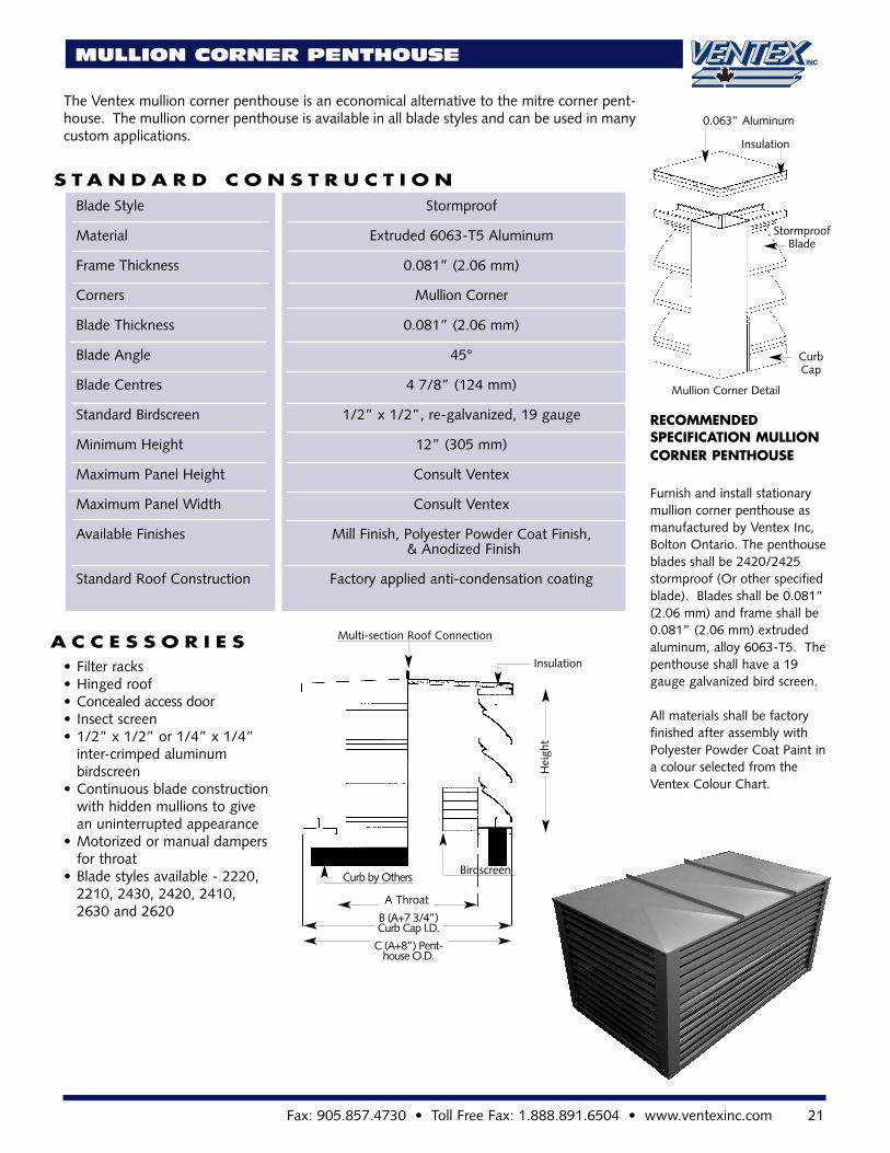
MULLION CORNER PENTHOUSE
The Ventex mullion corner penthouse is an economical alternative to the mitre corner pent-house. The mullion corner penthouse is available in all blade styles and can be used in manycustom applications.
S T A N D A R D C O N S T R U C T I O N
A C C E S S O R I E S
Blade Style Stormproof
Material Extruded 6063-T5 Aluminum
Frame Thickness 0.081” (2.06 mm)
Corners Mullion Corner
Blade Thickness 0.081” (2.06 mm)
Blade Angle 45°
Blade Centres 4 7/8” (124 mm)
Standard Birdscreen 1/2” x 1/2”, re-galvanized, 19 gauge
Minimum Height 12” (305 mm)
Maximum Panel Height Consult Ventex
Maximum Panel Width Consult Ventex
Available Finishes Mill Finish, Polyester Powder Coat Finish,& Anodized Finish
Standard Roof Construction Factory applied anti-condensation coating
• Filter racks• Hinged roof• Concealed access door• Insect screen• 1/2” x 1/2” or 1/4” x 1/4”
inter-crimped aluminum birdscreen
• Continuous blade constructionwith hidden mullions to give an uninterrupted appearance
• Motorized or manual dampers for throat
• Blade styles available - 2220, 2210, 2430, 2420, 2410, 2630 and 2620
RECOMMENDED SPECIFICATION MULLIONCORNER PENTHOUSE
Furnish and install stationarymullion corner penthouse asmanufactured by Ventex Inc,Bolton Ontario. The penthouseblades shall be 2420/2425stormproof (Or other specifiedblade). Blades shall be 0.081”(2.06 mm) and frame shall be0.081” (2.06 mm) extrudedaluminum, alloy 6063-T5. Thepenthouse shall have a 19gauge galvanized bird screen.
All materials shall be factoryfinished after assembly withPolyester Powder Coat Paint ina colour selected from the Ventex Colour Chart.
Multi-section Roof Connection
Insulation
Hei
ght
Birdscreen
C (A+8”) Pent-house O.D.
B (A+7 3/4”)Curb Cap I.D.
A Throat
Curb by Others
0.063” Aluminum
Insulation
StormproofBlade
CurbCap
Mullion Corner Detail
22 www.ventexinc.com • Phone 905.857.4700 • Toll Free Phone: 1.800.668.7214
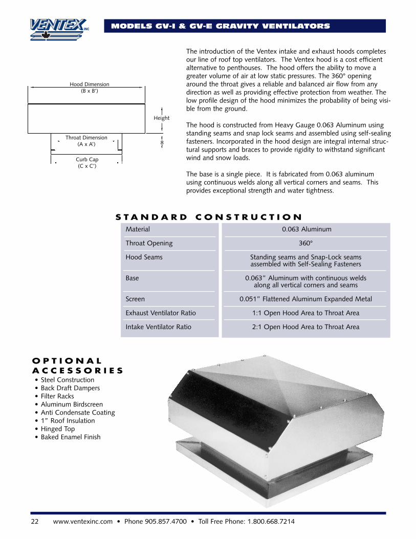
The introduction of the Ventex intake and exhaust hoods completesour line of roof top ventilators. The Ventex hood is a cost efficientalternative to penthouses. The hood offers the ability to move agreater volume of air at low static pressures. The 360° openingaround the throat gives a reliable and balanced air flow from anydirection as well as providing effective protection from weather. Thelow profile design of the hood minimizes the probability of being visi-ble from the ground.
The hood is constructed from Heavy Gauge 0.063 Aluminum usingstanding seams and snap lock seams and assembled using self-sealingfasteners. Incorporated in the hood design are integral internal struc-tural supports and braces to provide rigidity to withstand significantwind and snow loads.
The base is a single piece. It is fabricated from 0.063 aluminumusing continuous welds along all vertical corners and seams. Thisprovides exceptional strength and water tightness.
MODELS GV-I & GV-E GRAVITY VENTILATORS
S T A N D A R D C O N S T R U C T I O N
O P T I O N A LA C C E S S O R I E S
Material 0.063 Aluminum
Throat Opening 360°
Hood Seams Standing seams and Snap-Lock seamsassembled with Self-Sealing Fasteners
Base 0.063” Aluminum with continuous welds along all vertical corners and seams
Screen 0.051” Flattened Aluminum Expanded Metal
Exhaust Ventilator Ratio 1:1 Open Hood Area to Throat Area
Intake Ventilator Ratio 2:1 Open Hood Area to Throat Area
• Steel Construction• Back Draft Dampers• Filter Racks• Aluminum Birdscreen• Anti Condensate Coating• 1” Roof Insulation• Hinged Top• Baked Enamel Finish
Hood Dimension(B x B’)
Height
8Throat Dimension
(A x A’)
Curb Cap(C x C’)
Fax: 905.857.4730 • Toll Free Fax: 1.888.891.6504 • www.ventexinc.com 23
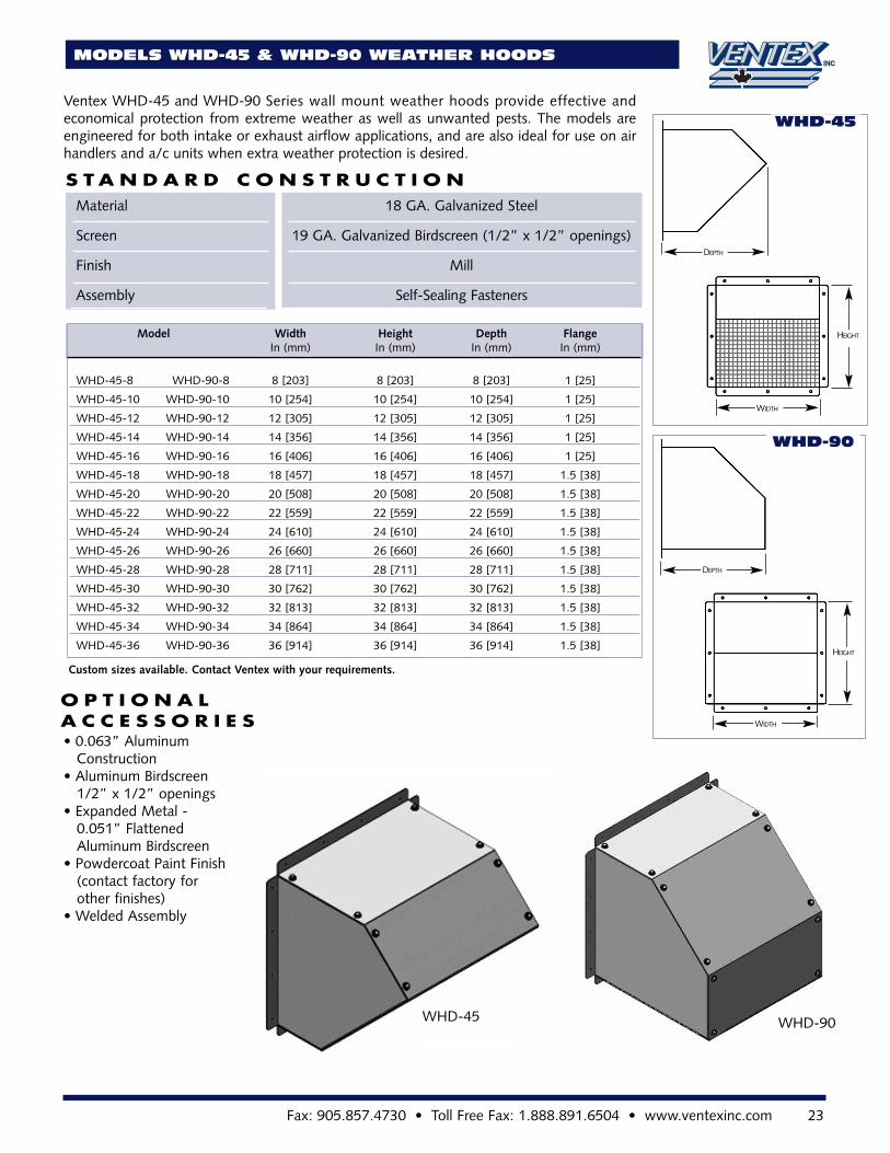
MODELS WHD-45 & WHD-90 WEATHER HOODS
Ventex WHD-45 and WHD-90 Series wall mount weather hoods provide effective andeconomical protection from extreme weather as well as unwanted pests. The models areengineered for both intake or exhaust airflow applications, and are also ideal for use on airhandlers and a/c units when extra weather protection is desired.
S T A N D A R D C O N S T R U C T I O N
O P T I O N A LA C C E S S O R I E S
Material 18 GA. Galvanized Steel
Screen 19 GA. Galvanized Birdscreen (1/2” x 1/2” openings)
Finish Mill
Assembly Self-Sealing Fasteners
• 0.063” Aluminum Construction
• Aluminum Birdscreen 1/2” x 1/2” openings
• Expanded Metal - 0.051” Flattened Aluminum Birdscreen
• Powdercoat Paint Finish (contact factory for other finishes)
• Welded Assembly
Model Width Height Depth FlangeIn (mm) In (mm) In (mm) In (mm)
WHD-45-8 WHD-90-8 8 [203] 8 [203] 8 [203] 1 [25]
WHD-45-10 WHD-90-10 10 [254] 10 [254] 10 [254] 1 [25]
WHD-45-12 WHD-90-12 12 [305] 12 [305] 12 [305] 1 [25]
WHD-45-14 WHD-90-14 14 [356] 14 [356] 14 [356] 1 [25]
WHD-45-16 WHD-90-16 16 [406] 16 [406] 16 [406] 1 [25]
WHD-45-18 WHD-90-18 18 [457] 18 [457] 18 [457] 1.5 [38]
WHD-45-20 WHD-90-20 20 [508] 20 [508] 20 [508] 1.5 [38]
WHD-45-22 WHD-90-22 22 [559] 22 [559] 22 [559] 1.5 [38]
WHD-45-24 WHD-90-24 24 [610] 24 [610] 24 [610] 1.5 [38]
WHD-45-26 WHD-90-26 26 [660] 26 [660] 26 [660] 1.5 [38]
WHD-45-28 WHD-90-28 28 [711] 28 [711] 28 [711] 1.5 [38]
WHD-45-30 WHD-90-30 30 [762] 30 [762] 30 [762] 1.5 [38]
WHD-45-32 WHD-90-32 32 [813] 32 [813] 32 [813] 1.5 [38]
WHD-45-34 WHD-90-34 34 [864] 34 [864] 34 [864] 1.5 [38]
WHD-45-36 WHD-90-36 36 [914] 36 [914] 36 [914] 1.5 [38]
WHD-45
WHD-90
WHD-45 WHD-90
Custom sizes available. Contact Ventex with your requirements.
HEIGHT
WIDTH
DEPTH
DEPTH
HEIGHT
WIDTH
24 www.ventexinc.com • Phone 905.857.4700 • Toll Free Phone: 1.800.668.7214
ACL ACOUSTIC LOUVER
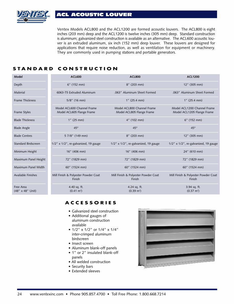
Ventex Models ACL800 and the ACL1200 are formed acoustic louvers. The ACL800 is eightinches (203 mm) deep and the ACL1200 is twelve inches (305 mm) deep. Standard constructionis aluminum; galvanized steel construction is available as an alternative. The ACL600 acoustic lou-ver is an extruded aluminum, six inch (152 mm) deep louver. These louvers are designed forapplications that require noise reduction, as well as ventilation for equipment or machinery.They are commonly used in pumping stations and portable generators.
• Galvanized steel construction• Additional gauges of
aluminum construction available
• 1/2” x 1/2” or 1/4” x 1/4” inter-crimped aluminumbirdscreen
• Insect screen• Aluminum blank-off panels• 1” or 2” insulated blank-off
panels• All welded construction• Security bars• Extended sleeves
S T A N D A R D C O N S T R U C T I O N
A C C E S S O R I E S
Model ACL600 ACL800 ACL1200
Depth 6” (152 mm) 8” (203 mm) 12” (305 mm)
Material 6063-T5 Extruded Aluminum .063” Aluminum Sheet Formed .063” Aluminum Sheet Formed
Frame Thickness 5/8” (16 mm) 1” (25.4 mm) 1” (25.4 mm)
Model ACL600 Channel Frame Model ACL800 Channel Frame Model ACL1200 Channel FrameFrame Styles Model ACL605 Flange Frame Model ACL805 Flange Frame Model ACL1205 Flange Frame
Blade Thickness 1” (25 mm) 4” (102 mm) 6” (152 mm)
Blade Angle 45° 45° 45°
Blade Centres 5 7/8” (149 mm) 8” (203 mm) 12” (305 mm)
Standard Birdscreen 1/2” x 1/2”, re-galvanized, 19 gauge 1/2” x 1/2”, re-galvanized, 19 gauge 1/2” x 1/2”, re-galvanized, 19 gauge
Minimum Height 16” (406 mm) 16” (406 mm) 24” (610 mm)
Maximum Panel Height 72” (1829 mm) 72” (1829 mm) 72” (1829 mm)
Maximum Panel Width 60” (1524 mm) 60” (1524 mm) 60” (1524 mm)
Available Finishes Mill Finish & Polyester Powder Coat Mill Finish & Polyester Powder Coat Mill Finish & Polyester Powder CoatFinish Finish Finish
Free Area 4.40 sq. ft. 4.24 sq. ft. 3.94 sq. ft.(48” x 48” Unit) (0.41 m2) (0.39 m2) (0.37 m2)
Fax: 905.857.4730 • Toll Free Fax: 1.888.891.6504 • www.ventexinc.com 25
ACL ACOUSTIC LOUVER
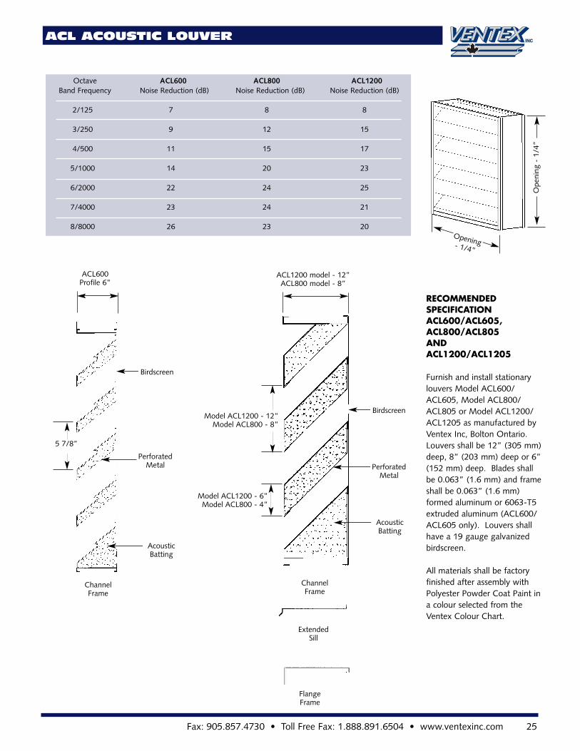
RECOMMENDED SPECIFICATIONACL600/ACL605,ACL800/ACL805 ANDACL1200/ACL1205
Furnish and install stationarylouvers Model ACL600/ACL605, Model ACL800/ACL805 or Model ACL1200/ACL1205 as manufactured byVentex Inc, Bolton Ontario.Louvers shall be 12” (305 mm)deep, 8” (203 mm) deep or 6”(152 mm) deep. Blades shallbe 0.063” (1.6 mm) and frameshall be 0.063” (1.6 mm)formed aluminum or 6063-T5extruded aluminum (ACL600/ACL605 only). Louvers shallhave a 19 gauge galvanizedbirdscreen.
All materials shall be factoryfinished after assembly withPolyester Powder Coat Paint ina colour selected from theVentex Colour Chart.
Octave ACL600 ACL800 ACL1200Band Frequency Noise Reduction (dB) Noise Reduction (dB) Noise Reduction (dB)
2/125 7 8 8
3/250 9 12 15
4/500 11 15 17
5/1000 14 20 23
6/2000 22 24 25
7/4000 23 24 21
8/8000 26 23 20
Ope
ning
-1/
4”
Opening- 1/4”
Birdscreen
PerforatedMetal
AcousticBatting
ACL1200 model - 12”ACL800 model - 8”
Model ACL1200 - 12”Model ACL800 - 8”
Model ACL1200 - 6”Model ACL800 - 4”
ChannelFrame
ExtendedSill
FlangeFrame
ACL600Profile 6”
AcousticBatting
PerforatedMetal
Birdscreen
5 7/8”
ChannelFrame
26 www.ventexinc.com • Phone 905.857.4700 • Toll Free Phone: 1.800.668.7214
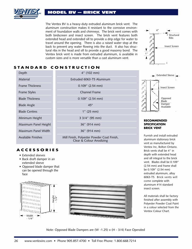
The Ventex BV is a heavy-duty extruded aluminum brick vent. Thealuminum construction makes it resistant to the corrosive environ-ment of foundation walls and chimneys. The brick vent comes withboth birdscreen and insect screen. The brick vent features bothextended head and extended sill to provide a drip edge for water totravel around the opening. There is also a raised water stop at theback to prevent any water flowing into the duct. It also has struc-tural ribs in the head and sill to provide a good masonry bond. TheVentex brick vent is made from extruded aluminum, is available incustom sizes and is more versatile than a cast aluminum vent.
S T A N D A R D C O N S T R U C T I O N
A C C E S S O R I E S• Extended sleeves• Back draft damper in an
extended sleeve• Opposed blade damper that
can be opened through the face
RECOMMENDED SPECIFICATIONBRICK VENT
Furnish and install extrudedaluminum stationary brickvent as manufactured byVentex Inc, Bolton Ontario.Brick vents shall be 4” indepth with extended headand sill integral to the brickvent. Blades shall be 0.109”(2.54 mm) and frame shallbe 0.109” (2.54 mm)extruded aluminum, alloy6063-T5. Brick vents willcome complete with aluminum #14 standardinsect screen.
All materials shall be factoryfinished after assembly withPolyester Powder Coat Paintin a colour selected from theVentex Colour Chart.
Opposed Blade Damper Available
Insect Screen
Extended Sleeve
Insect Screen
StructuralRibs
1”
4”
Hei
ght
-1/
4”
Width - 1/4”
Depth 4” (102 mm)
Material Extruded 6063-T5 Aluminum
Frame Thickness 0.109” (2.54 mm)
Frame Styles Channel Frame
Blade Thickness 0.109” (2.54 mm)
Blade Angle 45°
Blade Centres 1” (25 mm)
Minimum Height 3 3/4” (95 mm)
Maximum Panel Height 36” (914 mm)
Maximum Panel Width 36” (914 mm)
Available Finishes Mill Finish, Polyester Powder Coat Finish, Clear & Colour Anodizing
Note: Opposed Blade Dampers are (W -1.25) x (H - 3/4) Face Operated
MODEL BV — BRICK VENT
Fax: 905.857.4730 • Toll Free Fax: 1.888.891.6504 • www.ventexinc.com 27
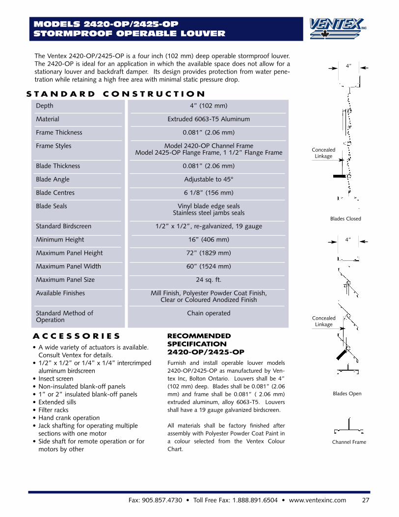
The Ventex 2420-OP/2425-OP is a four inch (102 mm) deep operable stormproof louver.The 2420-OP is ideal for an application in which the available space does not allow for astationary louver and backdraft damper. Its design provides protection from water pene-tration while retaining a high free area with minimal static pressure drop.
S T A N D A R D C O N S T R U C T I O N
A C C E S S O R I E S
Depth 4” (102 mm)
Material Extruded 6063-T5 Aluminum
Frame Thickness 0.081” (2.06 mm)
Frame Styles Model 2420-OP Channel FrameModel 2425-OP Flange Frame, 1 1/2” Flange Frame
Blade Thickness 0.081” (2.06 mm)
Blade Angle Adjustable to 45°
Blade Centres 6 1/8” (156 mm)
Blade Seals Vinyl blade edge sealsStainless steel jambs seals
Standard Birdscreen 1/2” x 1/2”, re-galvanized, 19 gauge
Minimum Height 16” (406 mm)
Maximum Panel Height 72” (1829 mm)
Maximum Panel Width 60” (1524 mm)
Maximum Panel Size 24 sq. ft.
Available Finishes Mill Finish, Polyester Powder Coat Finish,Clear or Coloured Anodized Finish
Standard Method of Chain operatedOperation
• A wide variety of actuators is available. Consult Ventex for details.
• 1/2” x 1/2” or 1/4” x 1/4” intercrimped aluminum birdscreen
• Insect screen• Non-insulated blank-off panels• 1” or 2” insulated blank-off panels• Extended sills• Filter racks• Hand crank operation• Jack shafting for operating multiple
sections with one motor• Side shaft for remote operation or for
motors by other
Furnish and install operable louver models2420-OP/2425-OP as manufactured by Ven-tex Inc, Bolton Ontario. Louvers shall be 4”(102 mm) deep. Blades shall be 0.081” (2.06mm) and frame shall be 0.081” ( 2.06 mm)extruded aluminum, alloy 6063-T5. Louversshall have a 19 gauge galvanized birdscreen.
All materials shall be factory finished afterassembly with Polyester Powder Coat Paint ina colour selected from the Ventex ColourChart.
RECOMMENDEDSPECIFICATION2420-OP/2425-OP
MODELS 2420-OP/2425-OP STORMPROOF OPERABLE LOUVER
4”
ConcealedLinkage
Blades Closed
ConcealedLinkage
Blades Open
4”
Channel Frame
28 www.ventexinc.com • Phone 905.857.4700 • Toll Free Phone: 1.800.668.7214
MODEL 1200 EXTRUDED BACK DRAFT DAMPER
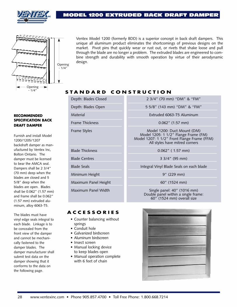
Ventex Model 1200 (formerly BDD) is a superior concept in back draft dampers. Thisunique all aluminum product eliminates the shortcomings of previous designs on themarket. Pivot pins that quickly wear or rust out, or rivets that shake loose and pullthrough the blade are no longer a problem. The extruded blades are engineered to com-bine strength and durability with smooth operation by virtue of their aerodynamicdesign.
S T A N D A R D C O N S T R U C T I O N
A C C E S S O R I E S
Depth: Blades Closed 2 3/4” (70 mm) “DM” & “FM”
Depth: Blades Open 5 5/8” (143 mm) “DM” & “FM”
Material Extruded 6063-T5 Aluminum
Frame Thickness 0.062” (1.57 mm)
Frame Styles Model 1200: Duct Mount (DM)Model 1205: 1 1/2” Flange Frame (FM)
Model 1207: 1 1/2” Front Flange Frame (FFM)All styles have mitred corners
Blade Thickness 0.062” ( 1.57 mm)
Blade Centres 3 3/4” (95 mm)
Blade Seals Integral Vinyl Blade Seals on each blade
Minimum Height 9” (229 mm)
Maximum Panel Height 60” (1524 mm)
Maximum Panel Width Single panel: 40” (1016 mm)Double panel within a single frame:
60” (1524 mm) overall size
• Counter balancing without springs
• Conduit hole• Galvanized birdscreen• Aluminum birdscreen• Insect screen• Manual locking device
to keep blades open• Manual operation complete
with 6 feet of chain
RECOMMENDED SPECIFICATION BACKDRAFT DAMPER
Furnish and install Model1200/1205/1207backdraft damper as man-ufactured by Ventex Inc,Bolton Ontario. Thedamper must be licensedto bear the AMCA seal.Dampers shall be 2 3/4”(70 mm) deep when theblades are closed and 55/8” deep when theblades are open. Bladesshall be 0.062” (1.57 mm)and frame shall be 0.062”(1.57 mm) extruded alu-minum, alloy 6063-T5.
The blades must havevinyl edge seals integral toeach blade. Linkage is tobe concealed from thefront view of the damperand cannot be mechani-cally fastened to thedamper blades. Thedamper manufacturer shallsubmit test data on thedamper showing that itconforms to the data onthe following page.
Opening- 1/4”
Opening- 1/4”
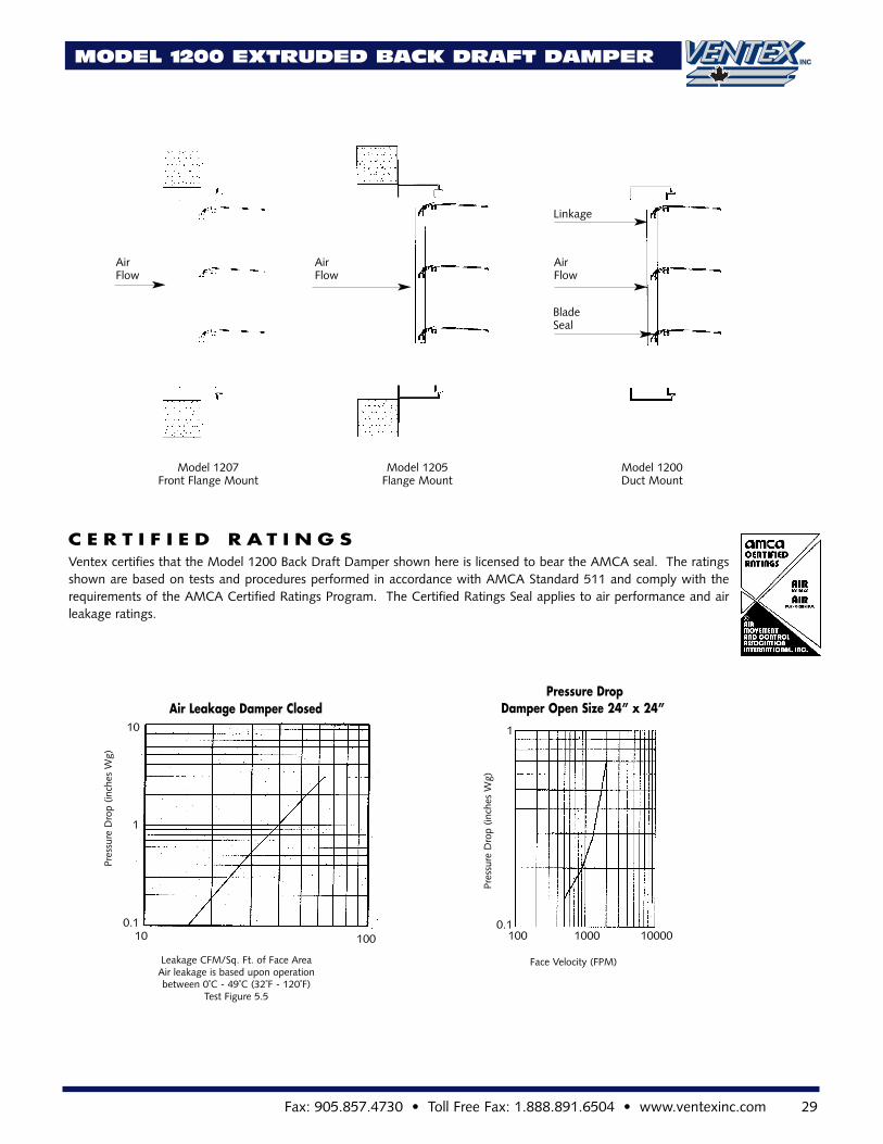
Air Leakage Damper Closed
0.1
Leakage CFM/Sq. Ft. of Face AreaAir leakage is based upon operation between 0˚C - 49˚C (32˚F - 120˚F)
Test Figure 5.5
Pres
sure
Dro
p(in
ches
Wg)
1
10
10 1000.1
Face Velocity (FPM)
Pres
sure
Dro
p(in
ches
Wg)
1
100 100001000
Ventex certifies that the Model 1200 Back Draft Damper shown here is licensed to bear the AMCA seal. The ratingsshown are based on tests and procedures performed in accordance with AMCA Standard 511 and comply with therequirements of the AMCA Certified Ratings Program. The Certified Ratings Seal applies to air performance and airleakage ratings.
C E R T I F I E D R A T I N G S
Model 1207 Front Flange Mount
Model 1205Flange Mount
Model 1200Duct Mount
Air Flow
Air Flow
Air Flow
BladeSeal
Linkage
MODEL 1200 EXTRUDED BACK DRAFT DAMPER
Pressure DropDamper Open Size 24” x 24”
Fax: 905.857.4730 • Toll Free Fax: 1.888.891.6504 • www.ventexinc.com 29
30 www.ventexinc.com • Phone 905.857.4700 • Toll Free Phone: 1.800.668.7214
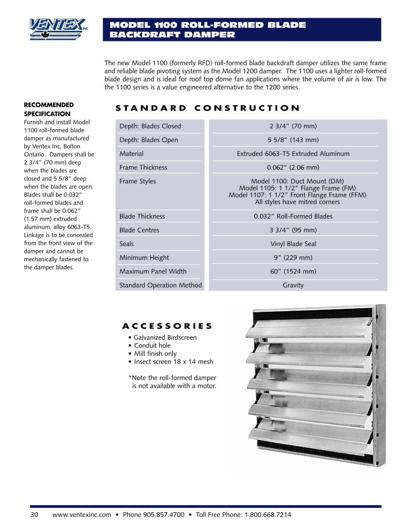
The new Model 1100 (formerly RFD) roll-formed blade backdraft damper utilizes the same frameand reliable blade pivoting system as the Model 1200 damper. The 1100 uses a lighter roll-formedblade design and is ideal for roof top dome fan applications where the volume of air is low. Thethe 1100 series is a value engineered alternative to the 1200 series.
S T A N D A R D C O N S T R U C T I O N
MODEL 1100 ROLL-FORMED BLADEBACKDRAFT DAMPER
Depth: Blades Closed 2 3/4” (70 mm)
Depth: Blades Open 5 5/8” (143 mm)
Material Extruded 6063-T5 Extruded Aluminum
Frame Thickness 0.062” (2.06 mm)
Frame Styles Model 1100: Duct Mount (DM)Model 1105: 1 1/2” Flange Frame (FM)
Model 1107: 1 1/2” Front Flange Frame (FFM)All styles have mitred corners
Blade Thickness 0.032” Roll-Formed Blades
Blade Centres 3 3/4” (95 mm)
Seals Vinyl Blade Seal
Minimum Height 9” (229 mm)
Maximum Panel Width 60” (1524 mm)
Standard Operation Method Gravity
A C C E S S O R I E S• Galvanized Birdscreen• Conduit hole• Mill finish only• Insect screen 18 x 14 mesh
*Note the roll-formed damper is not available with a motor.
RECOMMENDED SPECIFICATION Furnish and install Model1100 roll-formed bladedamper as manufacturedby Ventex Inc, BoltonOntario. Dampers shall be2 3/4” (70 mm) deepwhen the blades areclosed and 5 5/8” deepwhen the blades are open.Blades shall be 0.032” roll-formed blades andframe shall be 0.062”(1.57 mm) extruded aluminum, alloy 6063-T5.Linkage is to be concealedfrom the front view of thedamper and cannot bemechanically fastened tothe damper blades.
Fax: 905.857.4730 • Toll Free Fax: 1.888.891.6504 • www.ventexinc.com 31
S T A N D A R D C O N S T R U C T I O N
A C C E S S O R I E S
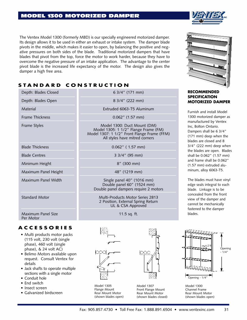
Depth: Blades Closed 6 3/4” (171 mm)
Depth: Blades Open 8 3/4” (222 mm)
Material Extruded 6063-T5 Aluminum
Frame Thickness 0.062” (1.57 mm)
Frame Styles Model 1300: Duct Mount (DM)Model 1305: 1 1/2” Flange Frame (FM)
Model 1307: 1 1/2” Front Flange Frame (FFM)All styles have mitred corners
Blade Thickness 0.062” ( 1.57 mm)
Blade Centres 3 3/4” (95 mm)
Minimum Height 8” (300 mm)
Maximum Panel Height 48” (1219 mm)
Maximum Panel Width Single panel 40” (1016 mm)Double panel 60” (1524 mm)
Double panel dampers require 2 motors
Standard Motor Multi-Products Motor Series 28132 Position, External Spring Return
UL & CSA Approved
Maximum Panel Size 11.5 sq. ft.Per Motor
• Multi products motor packs (115 volt, 230 volt (single phase), 460 volt (single phase), & 24 volt AC)
• Belimo Motors available upon request. Consult Ventex for details
• Jack shafts to operate multiple sections with a single motor
• Conduit hole• End switch• Insect screen• Galvanized birdscreen
RECOMMENDED SPECIFICATIONMOTORIZED DAMPER
Furnish and install Model1300 motorized damper asmanufactured by VentexInc, Bolton Ontario.Dampers shall be 6 3/4”(171 mm) deep when theblades are closed and 83/4” (222 mm) deep whenthe blades are open. Bladesshall be 0.062” (1.57 mm)and frame shall be 0.062”(1.57 mm) extruded alu-minum, alloy 6063-T5.
The blades must have vinyledge seals integral to eachblade. Linkage is to be concealed from the frontview of the damper andcannot be mechanically fastened to the damperblades.
MODEL 1300 MOTORIZED DAMPER
Model 1305Flange MountRear Mount Motor(shown blades open)
Model 1307Front Flange MountRear Mount Motor(shown blades closed)
Opening - 1/4”
Model 1300Channel FrameRear Mount Motor (shown blades open)
The Ventex Model 1300 (formerly MBD) is our specially engineered motorized damper.Its design allows it to be used in either an exhaust or intake system. The damper bladepivots in the middle, which makes it easier to open, by balancing the positive and neg-ative pressures on both sides of the blade. Traditional motorized dampers that haveblades that pivot from the top, force the motor to work harder, because they have toovercome the negative pressure of an intake application. The advantage to the centerpivot blade is the increased life expectancy of the motor. The design also gives thedamper a high free area.
Opening- 1/4”
Featuring:• Insulated Thermal Break Control Dampers
• Static and Dynamic Fire Dampers
• Airfoil Blade Control Dampers
• Stainless Steel Fire Dampers
• Steel Control Dampers
Also Available:
LVR-CAT AUGUST 2013
V E N T E X I N C .1 9 5 H E A L E Y R O A D
B O L T O N , O N T A R I O
9 0 5 • 8 5 7 • 4 7 0 01 • 8 0 0 • 6 6 8 • 7 2 1 4
Fax: 1 • 8 8 8 • 8 9 1 • 6 5 0 4w w w . v e n t e x i n c . c o m
BUILT ON SERVICE. BUILT-IN QUALITY.©
DAMPERPRODUCTS CATALOG
For the most current information please visit
www.ventexinc.com


![Louvers Selection[1]](https://img.pdfslide.us/doc/110x75/577c7f031a28abe054a2dc2f/louvers-selection1.jpg)