Embed Size (px)
Citation preview

ControlKeeper® Touchscreen
Programming Guide& User Manual
Version 5.7
��
�
��
Venergy Advanced Metering System

p1
Contents Contents 1
Safety Instructions 3
Chapter 1: Introduction 4
Overview 4
Chapter 2: Touchscreen Navigation 5
General Information 5 Touchscreen Navigation 5
Chapter 3: Initial Panel Setup 9
Preparing the Panel for Programming 9
Chapter 4: Basic Programming 14
Basic Programming Part 1: Relay Setup 14 Basic Programming Part 2: Time Schedule Setup 16 Basic Programming Part 3: Setting Up Contact Closure Switches 18 Basic Programming Part 4: Setting Up Greengate Digital Switches (GDS) 23 Basic Programming Part 5: Setting up Analogs 30 Basic Programming Part 6: Setting up Remotes 35 Basic Programming Part 7: Setting up Holiday Dates 38
Chapter 5: Advanced Programming 40
Using ControlKeeper Priorities 40 Using Masks in the ControlKeeper System 42
Chapter 6: Reviewing Programming 45
Reviewing Programming by Relay 45 Reviewing Programming Settings 46
Chapter 7: Changing or Deleting Programming 48
Changing Programming through the Setup Screens 48 Deleting Time Schedules and Holiday Dates 48
Chapter 8: Viewing Live Status 50
Live Relay Status 50 Live Switch Status 52 Live Analog Status 53 Live Remote Status 53
Chapter 9: Using Logs 55
Viewing Relay and Input Logs 55 Viewing System Logs 56 Viewing Relay Runtime 57 Clearing Logs 57
Chapter 10: Manually Turning Relays On and Off 59
Hardware Relay Overrides 59 Touchscreen Relay Overrides 60
Chapter 11: User Information 61
ControlKeeper T Maintenance 61

p2
ControlKeeper T Memory Information 61 Technical Support 61 Item Reference Diagrams 62
Appendix A: 63
Setting Digita Switch Parameters 63
Appendix B: 67
Relay Schedule Worksheet 68 Contact Closure Switch Input Worksheet 69 Greengate Digital Switch Worksheet 70 Analog Input Worksheet 71 Time Schedule Worksheet 71

p3
Safety Instructions IMPORTANT SAFEGUARDS When using electrical equipment, basic safety precautions should always be followed including the following:
READ AND FOLLOW ALL SAFETY INSTRUCTIONS Only Qualified Electricians should install the Lighting Control Equipment.
Install in accordance with National Electrical Code (NEC) or other codes that may apply.
Turn power OFF at circuit breakers before removing the chassis covers or when installing or wiring high voltage components.
All new wiring must be fully verified before applying power.
Document all wiring that is terminated to relays and other components for ease of future servicing and programming.
Ensure that high voltage and low voltage wiring remains separated and enters through the designated high and low voltage areas.
Equipment should not be mounted in locations where it will be readily subjected to tampering by unauthorized personnel.
The use of accessory equipment not recommended by the manufacturer may cause an unsafe condition.
Do not use this equipment for other than intended use and at the listed voltage.
Servicing of equipment should be performed by qualified service personnel.
SAVE THESE INSTRUCTIONS

p4
Chapter 1: Introduction This chapter provides a general overview of the programming concepts.
Overview Welcome to the ControlKeeper Touchscreen. Those of you who are new to the ControlKeeper family of lighting control will find this manual a useful tool in understanding how the system works and how to make the best use of the technology the system provides.
The first few chapters of this manual introduce you to the basic concepts of the Greengate lighting system, show you how to get technical assistance as you program your system, and lead you through setting up the initial configuration of the ControlKeeper panel.
The chapters that follow help you set up basic programming for your lighting loads: control by time of day and control by various types of input devices.
Later chapters discuss more advanced concepts in programming such as the use of priorities and masks, and introduce you to the use of the, input, output and system logs as troubleshooting tools.
How It Works The ControlKeeper Touchscreen (CKT) is a microcomputer-based controller that provides automated control of high voltage lighting circuits. The controller is programmed through an on-board touchscreen display. The CKT can operate as a stand-alone controller or in a network with other Greengate panels.
What are Relays? Each ControlKeeper T enclosure has up to 48 RELAYS that can be controlled by programs entered through the on-board touchscreen or through the optional Keeper Enterprise computer software. Lighting loads are wired from the electrical service panel into these relays in the ControlKeeper T (CKT) enclosure and then out to the lighting fixtures. Automated control of the relays is accomplished by setting up Inputs such as switches, analogs, time schedules, etc. to work with the relays.
What are Inputs? An INPUT is anything that is used to control the lighting circuits, such as a Time Schedule, a Dry Contact Closure from a wall switch or digital photosensor, a Digital Switch, an Analog Photosensor, or a command from an override
source Remote to the control panel. Any input can control any relay or number of relays. In addition, more than one input can control the same relay or number of relays.
How do I program Inputs to control Relays? To program these INPUTS to control the RELAYS, you must create a logical tie between them with the control panel programming. We call this ―tie‖ a LINK. This manual contains information on the different ways that an input can control a relay and provides step-by-step instructions on how to create the links between inputs and relays using the touchscreen display. The CKT can also be programmed using the optional Keeper Enterprise Software on your computer.
.

p5
Chapter 2: Touchscreen Navigation This section discusses the layout of the ControlKeeper T‘s screens. It also discusses how to navigate through the controls that the CKT uses for data entry.
General Information The ControlKeeper T has a 2‖ X 5‖ touchscreen display that allows access to a sequence of data entry and informational screens. The monochromatic display has been set up and calibrated for best viewing before the control panel leaves the factory.
If the screen should need cleaning, do not use any type of cleanser. It is recommended that only a soft cloth be used to clean the display.
Adjusting the Display Contrast: If it is necessary to change the display contrast because the display is too dark or too light, carefully adjust the contrast using the LCD Display Potentiometer located next to the board‘s capacitor. Turn to the left to make the display darker. Turn to the right to make the display lighter.
Touchscreen Navigation The ControlKeeper T has a 2‖ X 5‖ Touchscreen display that allows access to a sequence of data entry and informational screens. This manual tells you how to program the CKT using that display. All commands and procedures that are described in this manual can also be performed using the optional Keeper Enterprise Software. The information in this manual is provided to describe the touchscreen programming features available for those who do not purchase the Keeper Enterprise Software.
Main Screen The display defaults to showing the Main Status Screen when the Touchscreen is not in use.
If you have used the Panel Setup Tab option to display the splash screen, the display rotates between the two MAIN SCREENS: the Main Status Screen and the Splash Screen. A touch on either of these screens brings you into the ControlKeeper T programming interface.
Main Status Screen
The Main Status Screen shows the current status of all the relays. If there is no relay in a location in the enclosure, the box will appear grayed out. Relays that do exist will be displayed clearly. Status information is constantly being updated.
The Main Screen displays the panel name, address, and the current time and date. If the panel is running a Holiday Schedule, the letter H will be displayed next to the date indicating Holiday mode. Also, if the rocker switch override on the Relay Stack Control card has been used to turn all the relays on or off, the display will flash OVERRIDE ON or OVERRIDE OFF to indicate that the status shown for the relays is currently overridden.
When you touch a relay on the display, the screen switches to the Status Screen of that relay. For more information about the Relay Status Screen see ―Live Relay Status‖ on page 50.
When you touch the display at any point that is not a Relay, the screen switches to the Status Screen of the last relay accessed.
Splash Screen (Optional Display from the Panel Setup Tab)

p6
The Splash Screen shows the panel name, panel hardware address, and the current time and date. The ControlKeeper T automatically updates the time and date shown on the screen. If the rocker switch override on the Relay Stack Control card has been used to turn all the relays on or off, the display will flash OVERRIDE ON or OVERRIDE OFF to indicate that the status shown for the relays is currently overridden.
If the option to display the splash screen is chosen from the panel setup tab, the Splash Screen will be displayed for about 5 seconds in rotation with the Main Status Screen. A touch at any point on the Splash Screen will switch the display to the data entry or informational screen last accessed. When the Touchscreen has not been used for several minutes the display will return to the Main Screen rotation.
Programming and Informational Screens A touch on either of the Main Screens brings you to the ControlKeeper programming and reporting screens.
Screen Layout The display screens consist of four main areas:
1. Screen Tabs with horizontal scroll arrows, 2. Scrolling Region for Item List 3. Informational or data entry Window with vertical
scroll arrows if needed, and 4. Function Buttons
Screen Tabs
The ControlKeeper has eleven Screens or Screen Groups that you can access by using SCREEN TABS. These tabs are arranged on three ―pages‖.
The first page allows you to choose from the LIVE STATUS, RELAY, SWITCH AND SCHEDULE SCREEN Groups.
The Screen Tabs on the second page are ANALOG, REMOTE, MASK, AND HOLIDAY.
The third page tabs are ASTRONOMICAL CLOCK, CLOCK and PANEL SETUP.
Use the left and right arrows to scroll through the Screen Tabs one at a time until you see the screen or screen group that you want to access. Touch the tab to activate that screen.
Item Scrolling Region
This region allows you to scroll through the list of all of the items in the screen or screen group that you have chosen.
The double arrows move you backward or forward through the list by five entries. The single arrows move you backward or forward through the list one entry at a time. If you touch the single right or left arrow and hold it, the screen will automatically scroll through the list one item at a time, about every 1/3 of a second. If you touch and hold the double right or left arrow you will continue scrolling up or down the list of items five at a time, covering the whole list in just a few seconds.
Data Entry/Informational Window
This large area in the middle of the display screen shows status information or allows you to program the lighting control strategy.
Function Buttons
The function buttons at the bottom of the screen allow for access to other screens in a Screen Group, allow you to perform an action specific to that screen, to leave the screen and return to the Main Screens, or to save data that has been entered.
The specific buttons that appear at the bottom of each screen will vary depending on the type of screen you are viewing. When you touch a function button, it will appear to be pressed down. Function buttons that are not active will appear shadowed, as though they were physically up. In this sample, the SETUP button has been pressed.
Button Function
Save If you have not chosen the Auto-Save function you must touch this button to save any changes you have made to the data on the screen. See ―Field 3: Setting up the Auto-Save (Optional)‖ on page 10 for information about the Auto-Save function.

p7
Button Function
Status The STATUS button appears on the Relay, Switch, Analog, and Remote Screens. Touch the STATUS button to move to the Status Screen, where you can view current information about the relay, switch, analog or remote that you are viewing.
Setup Touch the SETUP button to navigate to the SETUP screen. This screen allows you to create a new entry in the database, edit an existing entry, or de-activate an existing entry.
Links The LINKS button in the Relay Screen Group moves you to a screen that displays all the inputs that have been linked to this particular relay.
The LINKS button in the Switch, Analog, Time Schedule & Remote Screens moves you to a screen where you can create a Link (or tie) between inputs and relays.
The LINKS button in the Mask Screen moves you to a screen where you can link a Mask to an Input.
Logs If relays, switches analogs and remotes have been set up to log, you can touch the LOGS button to view the log reports. These reports will show the operation of the relay, switch, analog or remote over a period of time.
The LOGS button on the Panel Setup Screen will show you entries in the System Log. These entries contain information about power interruptions and resets that may have occurred.
Quit Touch the QUIT button when you want to leave a data entry screen without saving any of the changes you have made. You will then return to the Main Screen. If you have made changes and touch the QUIT button without saving the changes you will see the following message:
Touch YES if you want to leave without saving, or touch NO quit the screen and return to data entry screen.
Data Entry Controls There are five types of data entry controls: Drop Down Arrow, Toggle Dot, Scrolling List, Check Box, and Option Choice.
Drop Down Arrow Some data entry fields require the use of a keypad for entering names, numbers, or punctuation.
Press the down arrow next to the field and a Touchscreen keypad will appear. The keypad will contain either alphanumeric characters or just numeric characters depending on the type of field being entered. Press the characters or numbers you want and then touch the Enter button to save the name or numbers.
In the alphanumeric key display, The SHIFT button takes you back and forth between the upper case and lower case keypads. Touch the PUNCTUATION button to see the punctuation keypad.
In the numeric key display, the screen will show the range of allowed values. A beep will sound if you enter a value that is not within the allowed range. Touch the CE button to clear the entry and enter new data. Touch the +/_ button to change from positive to negative numbers.
Toggle Dot The Toggle field has a DOT to the right of the entry textbox. Each time you touch the dot, the textbox will toggle between the possible entries for this field. Normally, a toggle field will have from 3 to 8 possible entries.
Scrolling List The Scrolling List is used when there are many choices for the data entry field, usually 10 or more. Touch the right or left arrows to scroll through the list of possible choices. Every time you touch the right

p8
arrow you will scroll one entry down the list. When you touch the left arrow you will scroll one entry up the list.
Larger lists such as lists of relays or time schedules will have double right and left arrows. The double arrows move you up or down the list by five entries.
If you touch a single right or left arrow and hold it, the scrolling will continue automatically, changing about every 1/3 of a second. If you touch and hold the double right or left arrow you will continue scrolling up or down the list of items five at a time, covering the whole list in just a few seconds.
Check Box A check box field is used where the possible entries are Yes or No. Touch the box next to the field name and a checkmark will appear. This indicates that yes, you do want to use this feature. Touching the check box again will remove the checkmark. A check box with no checkmark indicates that you do not want to use this feature.
Option Choice Touch the button to toggle between ON and OFF. When the button reads ON, the option has been enabled. When the button reads OFF, the option has been disabled. Every time you touch the button you will toggle between enabling and disabling the option.

p9
Chapter 3: Initial Panel Setup Regardless of ultimate strategy of your lighting control, it will be necessary to start out with a few basic steps to bring your controller on-line. This section will guide you through the basic set up steps that will prepare the panel for programming. This section contains information about the following:
Step 1: Powering the Panel Step 2: Clearing the Panel Memory Step 3: Setting the Panel Jumpers Step 4: Setting the Panel Parameters Step 5: Setting the Panel Clock and Date Step 6: Setting the Astronomical Clock Step 7: Gathering the Information Needed for Programming
Preparing the Panel for Programming This section discusses the initial panel setup. It assumes that the enclosure and panel have been installed per the provided installation instructions. In these steps, you will prepare the hardware and software configurations that identify the panel for programming and networking functions.
Step 1: Initial Power Up Sequence 1. Plug the communications cable (red CAT5
Cable provided) into the Relay Stack Controller Card (RSC) RJ jack located at the bottom of the enclosure.
2. Plug in the power cable (white plastic connector
with six wires attached) into the Relay Stack Controller Card (RSC). The controller display should power up and display the MAIN SCREEN.
3. Once power is applied, make certain that the status LED is flashing in the upper left corner of the logic board and that the Main Screen shows the relays that are installed in your enclosure (not shadow boxes). If the status LED is not flashing or if the display does not show all active relays, power down the logic board and check all connections. If the problem persists, contact technical support.
Step 2: Clearing Panel Memory We recommend that before you begin programming the ControlKeeper T you clear panel memory. This assures you that you are beginning with a clean database. To clear the panel memory:
1. Move the override rocker switch to the ALL ON position to hold lighting ON and maintain lighting during the procedure.
2. Reset the panel, using the Reset Button located next to the blinking Status LED at the top left corner of the logic board.
3. During the reset, the status LED will stop flashing. Wait for the status LED to start flashing again. Starting at any corner, touch one corner of the display after the other until all four corners have been pressed. If more than a minute goes by without all four corners being touched, or if you touch anywhere other than the four corners, the memory clear function will not be activated.
4. If you have successfully followed this procedure, a message will appear, asking if you really want to clear the panel. Press the YES option. If this message does not appear, repeat this procedure from step 2.
5. If you select YES to clear the panel to factory defaults, the panel will display a RELOADING message. Wait for this message to disappear before proceeding.

p10
Once the panel is programmed, remember to move the rocker switch to the AUTO position.
Step 3: Setting the Panel Jumpers 1. Once all wiring is checked and terminated, be
sure the two Local/Remote jumpers (J9 and J10) are in the proper position. Jumpers J9 and J10 must be in the LOCAL position in order to supply +24 VDC to the switch input center pin. The jumpers are factory set to the REMOTE position for panel protection during installation.
2. If your panel is in a network, be sure that the
Network Termination Jumpers are in the correct positions. Remove the network termination jumpers from all but the first and last ControlKeepers on the network.
Step 4: Setting the Panel Parameters You should begin programming the ControlKeeper by setting up the panel identification information through the panel setup screen. A panel name and address should be defined. It is also recommended that the CLEAR LOGS option be done to clear any data prior to the clock being set.
To make changes to the Panel Setup Screen:
1. If the PANEL SETUP tab is not visible on the screen use the arrows to scroll left or right until the tab appears. Touch the tab to view the Panel Setup Screen.
2. If you are not already in the Setup screen, touch
the SETUP button at the bottom of the screen.
3. Enter the desired information as described below. Once all changes are done, touch the SAVE button. If you do not want to save the changes, select the QUIT button. You will be asked if you want to leave the screen without saving the changes. (Remember to touch the CLEAR button under the Clear All Logs field when doing the initial setup.)
Field 1: Setting the Panel Name The panel name defaults to LCP#1. You can change this default name to any eight-character word that might be meaningful to the location or function of the panel. Touch the down arrow next to the name field and a keypad will appear. Press the characters you want and then touch the ENTER button to save the name or numbers.
Field 2: Setting the Panel Address In the CKT the panel address is set using the Panel Setup Screen. The Panel Address can be changed to any value between 1 and 254. If you have more than one ControlKeeper panel in your system, each panel should have its own unique panel address. Touch the down arrow next to the address field and a keypad will appear. Press the number you want and then touch the ENTER button.
Field 3: Setting up the Auto-Save (Optional) When Auto-Save is active, changes to the data screen will be saved automatically when you leave a screen. We recommend that you not use the auto-save feature until you are familiar with the control panel functions and programming.
Touch the Auto-Save checkbox if you would like to save your changes automatically, without needing to touch the save button. A checkmark will appear. Touch the box again to remove the checkmark and de-select the Auto-Save feature.
Field 4: Clear All Logs Command The Clear All Logs commands will discard all relay, switch, analog, remote and system logs from the controller so that the logs will start over from that point forward. Relay Run Times will not be cleared with this command.

p11
Field 5: Setting up the Sound (Optional) The ControlKeeper T confirms a touch to the screen with an audible click. It will also beep if you try to enter an illegal value in a numeric data field. The panel defaults to Sound enabled.
Touch the Sound checkbox to delete the checkmark if you do not want this audible feedback. Touch the checkbox again to restore the sound feature.
Field 6: Switch Bus Type The ControlKeeper T V5.7.0 and higher supports the Greengate Digital Switch architecture as well as has compatibility support for the previous Digita switch architecture. If this panel is being used with networked digital switches, select whether you are connected GDS stations (Greengate Digital Switches) or Digita stations. You cannot use a mixture of different switch station types on the same Digital Switch network bus. The diagram below shows the faceplates of these different switch types for clarification.
If you change the Switch Bus type, you will be prompted to verify you wish to make this change. If you have previously programmed a Digita or GDS switch in the Switch Inputs screens, the address parameters will be overwritten when the Switch Bus field is changed. Please be cautious when changing the Switch Bus type to avoid overwriting your current settings. Review all digital switch addresses if the Switch Bus type is changed.
Field 7: Show Splash Screen (Optional) The ControlKeeper T automatically defaults to the status screen as its main screen when the touchscreen is not in use. If you wish to display the system splash screen and have the display alternate between the splash screen and the main screen, checkmark this feature.
Field 8: Panel Type and Version This number shows the panel type and software version of the control panel. You cannot change the type or version number that is shown. This is informational only. If you contact Technical Support, the technician will need to know the software version number.
Step 5: Setting the Panel Clock The next step in the panel setup is to set the panel‘s clock. The clock time and date determines when time schedules are activated. The date and time zone information is also used in calculating the astronomical sunrise and sunset times and for running holiday schedules. If you change the time or date in the clock screen the controller will assume the properly scheduled state for the time and date entered when you leave the clock screen.
1. If the CLOCK Tab is not visible on the screen use the arrows to scroll left or right until the tab appears. Touch the tab to view the CLOCK Screen.
2. Setup the desired information as described
below. Once all changes are done, touch the Save button. The controller will assume the properly scheduled state for the time and date entered when you leave the clock screen. If you do not want to save the changes, touch the QUIT button to return to the MAIN SCREEN. You will be asked if you want to leave the screen without saving the changes.
Field 1: Setting the Panel Time: The control panel uses the 24-hour military style clock so be sure to set the time accordingly! For example 1 o'clock in the afternoon should be input as 1300. Touch the down arrow to the right of the Hour textbox. A numeric touchscreen keypad will appear. Touch the numbers you want, then touch the ENTER button. Repeat for the Minutes and seconds text box.

p12
Field 2: Setting the Panel Date Touch the down arrow to the right of the Day textbox. A numeric touchscreen keypad will appear. Touch the numbers you want, then touch the ENTER button. Do the same for the Month and Year text boxes.
Field 3: Setting the Panel Time Zone Touch the right or left arrows to scroll through the available time zones. Stop scrolling when you see the zone you need. Time zones in the continental United States will show the name of the zone as well as the number of hours from Greenwich Mean Time (GMT). For instance, EST is 5 hours behind GMT, PST is 8 hours behind GMT. Time zones outside the continental United States are represented by the hours difference between the local time and GMT, that is, the display will show the number of hours you must use to adjust local time to GMT.
Field 4: Setting up the Daylight Savings Option The control panel is factory set with daylight savings enabled. This means that it will automatically adjust the clock ahead 1 hour or back 1 hour when daylight savings time change occurs. If you live in an area that does not implement daylight savings, you will need to disable this option by touching the choice button to remove Daylight Savings Option. The button will then read OFF and appear to be pressed down. Touch the box again to re-instate the option.
Field 5: Review Clock Time and Date The review area of this screen will show you the clock and date in the controller based on the entries in the screen
Step 6: Setting the Astronomical Clock The control panel automatically calculates sunup and sundown times for your location using a built-in astronomical clock. These sunup and sundown times can then be used to define various time-related functions such as time schedules.
In order to calculate the sunup and sundown times for a location, the control panel needs to know the location‘s latitude and longitude. From the latitude, longitude, and current date, the control panel can accurately determine your sunup and sundown times. Latitude and longitude coordinates can be typically found from GPS devices or may be researched on the world wide web.
Due to local topology you may need to add or subtract time from the calculated sunup or sundown values. The control panel gives you the option to
offset the calculated sunup and sundown times. Offsets may be added at the Astro Clock Tab to affect the entire panel. Individual offsets may be added later on the time schedule to allow for schedules to occur at slightly different offset times.
To make changes to the Astronomical Clock:
1. If the ASTRO Clock Tab is not visible on the screen use the arrows to scroll left or right until the tab appears. Touch the tab to view the Astronomical Clock Setup Screen.
2. Enter the desired information as described
below. Once all changes are done, touch the SAVE button to save the changes. If you do not want to save the changes, touch the QUIT button to return to the Main Screen. You will be asked to confirm that you want to leave the screen without saving the changes.
Field 1: Setting the Latitude: You have a choice of North or South latitude. (North American locations should always use NORTH). Touch the DOT to the right of the Latitude choice box. Each time you touch the dot you will toggle between the entries. Stop when you see the one you want.
Set the Degrees of Latitude by touching the down arrow to the right of the text box. A drop-down touchscreen numeric keypad will appear. Touch the numbers you want, then touch the ENTER button. Do the same for the Minutes of Latitude.
Field 2: Setting the Longitude You have a choice of East or West longitude. (North American locations should always use WEST). Touch the DOT to the right of the Longitude choice box. Each time you touch the dot you will toggle between the entries. Stop when you see the one you want.
Set the Degrees of Longitude by touching the down arrow to the right of the text box. A drop-down touchscreen numeric keypad will appear. Touch the numbers you want, then touch the ENTER button. Do the same for the Minutes of Longitude.

p13
Field 3: Setting Sunup and Sundown Offsets Due to local topology and lighting fixture strike periods, it may be necessary to add or subtract time from the calculated sunup and sundown times. The offset values for Sunrise time and Sunset time can be different.
You can apply an additional offset time when you program time schedules using the astronomical clock times. Each time schedule can have different values for the schedule offset. See ―Field 3: Setting up a Schedule Time‖ on page 17 for further information on adding offsets to the schedules.
Touch the DOT to the right of the Offset Plus/Minus choice box. If you want to make the calculated time earlier, choose the Minus symbol (-). If you want to make the calculated time later, choose the Plus (+) symbol.
Touch the arrow to the right of the Offset Hours box. A touchscreen keypad will appear. Enter the hours you would like to add to or subtract from the calculated time, then touch the ENTER button. Do the same for the Offset Minutes.
Field 4: Reviewing Sunup and Sundown Time The review area of this screen will show you the calculated sunup and sundown time based on the entries in the screen fields.
Step 7: Gathering the Information You Will Need: Put together all the information that you will need to program the controller. This includes:
1. The location and function of the lighting loads controlled by each relay.
2. The desired time schedules for each controlled lighting zone.
3. Contact input wall switch information: channel that the wiring is brought to on the panel as well as the relays it controls.
4. Digital switch information: the digital switch button address scheme and the relays each button should control.
5. Analog photosensor information: input channel that the sensor wiring is brought to on the panel; the relay or relays that it is to control; and ambient lighting threshold levels at which the relays will be actuated.
If the Telephone Interface Module will be used, a list of desired phone codes and their associated controlled relays.
p14
Chapter 4: Basic Programming In many cases, you can create a simple lighting control strategy just by setting up RELAYS, SWITCHES, ANALOGS, TIME SCHEDULES and REMOTEs. Holiday Dates can also be used to run special schedules for defined days. This section of the manual will lead you through setting up the basic structure of a lighting control strategy.
Step 1: Relay Setup Step 2: Time Schedule Setup Step 3: Contact Input Switch Setup Step 4: Digital Switch Setup (GDS) Step 5: Analog Setup Step 6: Remote Setup Step 7: Holiday Dates Setup (Optional)
Basic Programming Part 1: Relay Setup Each ControlKeeper T can control up to 48 relays using programs that have been entered through the touchscreen or through the optional Keeper Enterprise Software.
The ControlKeeper T uses the IntelliRelay design meaning that the serial relay cards communicate their hardware configuration and location to the control panel.
By default, the controller will issue a close command with an ON and a open command with an OFF. Through programming you may choose to have the relay act differently. During a power outage, the relay will resume its actual hardware configuration regardless of the software configuration that you have defined for it.
Relays are numbered 1 through 48 with relay 1 being in the lower left corner of the enclosure; relay 2 being in the lower right. Relays number up from this point consecutively with odds being on the left and evens on the right. It is important to map the physical relay to the software relay for proper operation.
Step 1: Programming Relay Parameters The panel defaults to relays being the Normal type. It is not necessary to adjust default parameters in order for relays to operate. Custom parameters and naming may be assigned if necessary.
To access the Relay Setup Screen:
1. If the RELAY tab is not visible on the screen use the arrows to scroll left or right until the tab
appears. Touch the RELAY tab to view Relay Information.
2. Use the right and left arrow buttons to scroll
through the relays until a relay that has not been used shows in the Name textbox. Usually a relay that has not yet been defined will have the default Name and a Type NOT USED. The Relay Name defaults to RELAY#XX. Each relay‘s definition appears in the informational area of the screen as you scroll through the list.
3. Touch the SETUP button to get to the set up
screen.
4. Enter the desired information as described
below. Once changes are complete, touch the SAVE button to save the changes. You can also touch the QUIT button to return to the MAIN SCREEN. If you leave the screen without saving the changes, you will be asked if that is what you want. Touch the NO button to remain on the screen, or touch the YES button to leave without saving any changes.

p15
Field 1: Setting the Relay Name The default name is RELAY#XX. You can change that default name to a unique name of up to eight characters. We recommend that you use a name that refers to the location or the function of the load that the relay controls, such as ―2FL HALL‖.
Press the down arrow next to the relay name field and a touchscreen keypad will appear. Press the characters you want and then touch the ENTER button to save the name or numbers.
Field 2: Setting Relay Type You can use the software to configure a relay to act as NOT USED, NORMAL, INVERTED, SENTRY or PHANTOM. By default, all relay slots are set up to the Normal type, regardless of whether or not the relay is there. This allows you to program a logic panel that is not connected to a panel and place it into place later with no need to change programming.
When a relay is set to be Not Used, the relay will not respond to any commands.
The Normal type will respond to on and off commands, appropriately closing the relay on the ON command, and opening the relay on the OFF command.
The Inverted type will reverse the relay response to an on or an off command. Any switch, analog input, time schedule or remote command that is linked to the relay will do the opposite of the command being issued, i.e. an ON becomes an OFF and an OFF becomes an ON. If the relay is commanded via touchscreen or manual relay software command, the relay will assume the commanded ON or OFF state without the inversion.
The Sentry type provides a specific ON command sequence for use with special intelligent SENTRY style high voltage switches. When an ON command is received by a Sentry relay, the relay will turn OFF for 3 seconds then turn ON and remain ON cueing the intelligent switch to turn ON. If sentry switches are being used but the automatic ON function is not desired, the relay may be left at the NORMAL default. Note: A relay that has been defined to be a Sentry relay must also have a Sentry Type Warn set for it in order for the lighting to turn OFF properly. See ―Setting the Sentry Type Warn Feature‖ on page 15 concerning setting the Warn periods for a relay.
A Phantom relay is one that does not control an actual load and may not even exist in the ControlKeeper T enclosure. The Phantom relay differs from a Not Used relay in that it will respond to commands. It is mainly used in complex lighting strategies.
To set the relay TYPE, touch the DOT to the right of the Type choice box. Each time you touch the dot you will toggle through the list of possible entries. Stop when you see the one you want.
Field 3: Setting Relay Warn The standard Warn feature is designed to notify the occupants of an area that the lights are about to go off. An additional Sentry Warn feature is available to allow for the use of intelligent sentry style high voltage switches.
You must first ENABLE THE RELAY TO WARN by setting the Relay Type and then defining the type of Warn you want issued. Once you have done this, time schedules set for off commands will INITIATE the warn sequence. If you want switches, analogs, or remotes to INITIATE a warn sequence when turned off, you must choose this option for them when you define them. See ―Field 8: Setting Switch Warn Off‖ on page 20, ―Field 6: Setting Up Analog Warn Off‖ on page 32, and ―Field 6: Setting Up Remote Warn Off‖ on page 37 for information on setting Switches, Analogs and Remotes to warn.
Setting the Standard Warn Feature
With the Standard Warn feature, the relays flash OFF then back ON when an OFF command is received. After the warning flash, the relays stay ON for a user-defined length of time before going OFF. This type of Warn is used with relays defined as type Normal, Inverted or Phantom.
To enable the Standard Warn:
1. Touch the drop down arrow to the right of the numeric entry field for the Warn Minutes.
2. Using the numeric keypad that appears enter the time you would like to occur between the warning flash and the final OFF command. This time can be set both in minutes and seconds.
Setting the Sentry Type Warn Feature
The Sentry Warn sequence is used with a lighting load that has special, intelligent line voltage switches. These switches call for different sequences of on/off commands to control the loads. Under the Warn OFF option, you have the ability to choose from two kinds of Sentry Type Warns. The type of Sentry Warn to choose depends on the type of intelligent line voltage switch you are using.
Sentry Type 1 Warn When a relay is configured for a Sentry Type 1
Warn and an OFF is issued, the Relay will flash OFF for 1 second, ON for 1 minute, OFF for 5 seconds, then turn ON and remain ON ready for the Sentry Switch‘s next command.

p16
Sentry Type 2 Warn When a relay is configured for a Sentry Type 2
Warn and an OFF is issued, the relay will go OFF for 1.5 seconds, then back ON.
Setting a Sentry Warn: Touch the box next to the desired Sentry Warn type. A checkmark will appear. This will enable the warning feature for any time scheduled OFF. To remove the Sentry option, touch the screen again.
Field 4: Viewing Relay Runtime The ControlKeeper T keeps a running total of the hours that each relay has been ON. The Relay Setup Screen shows the accumulated ON time as the Runtime for the relay since the last time the field was cleared. Touch the CLEAR button to clear the runtime and begin accumulating again from zero. The Relay Status Screen also displays the accumulated runtime.
Please note that the relay runtime will not reflect whether the RSC ALL ON or ALL OFF switch has been used to override the normal programming. In addition, if a panel has been powered down for an extended period of time, this field may reflect inaccurate data until the field has been cleared.
Field 5: Setting a Relay to Broadcast If you have a NETWORK of ControlKeeper T panels, there may be a time when you would like a relay in one ControlKeeper to act as an input to relays in other panels in the network - to have those remote relays act in parallel with the relay in the panel you are programming. You can do this by setting the relay to Broadcast onto the network whenever it turns on or off. That broadcast consists of the relay‘s name and the relay‘s new ON/OFF state. You would then set up the broadcast relay name as a Remote Input in the receiving panel. See ―Basic Programming Part 6: Setting up Remotes‖ on page 35 for more information.
To choose to broadcast the relay, touch the checkbox next to the Broadcast feature. A checkmark will appear. To remove the broadcast feature, touch the checkbox again, and the checkmark will disappear.
Field 6: Setting Relay Logging Relay Logs are a great tool for troubleshooting your lighting system. When the log feature is selected for a relay, the control panel maintains a listing of each relay actuation, including the relay name, ON/OFF status, time and date of change, and cause of change.
To choose to log the relay actuations, touch the checkbox next to the Log feature. A checkmark will
appear. To remove the log feature, touch the checkbox again, and the checkmark will disappear.
Basic Programming Part 2: Time Schedule Setup You need to program time schedules if your lighting control strategy includes turning lights on and off on a regular basis throughout the week. In the Greengate system, an ON schedule does not need to have a corresponding OFF time or vice versa. ON and OFF schedules for the same relays are programmed as separate schedules allowing for maximum flexibility. There are two steps to setting up a time schedule. The first is to set up the time schedule parameters. The second is to link the time schedule to the relays that it needs to control.
Step 1: Setting up the Time Schedule A time schedule must be defined with a Time, a Command, a command Priority level, and an active Day-of-week.
The Setup Screen allows you to SET UP a new time schedule or to CHANGE the definition of an existing schedule. To set up a Time Schedule:
1. If the SCHEDULE tab is not visible on the screen use the arrows to scroll left or right until the Schedule tab appears. Touch the tab to view Schedule Information.
2. Use the right and left arrow buttons to scroll
through the schedules until you see a time schedule that has not yet been defined. An unused time schedule will have the time ‖ --:--‖ in the Schedule Time textbox. Time Schedules are stored and viewed in chronological order. Each schedule‘s definition appears in the informational area of the screen as you scroll through the list.
3. If you are not already on the Setup Screen,
touch the SETUP button.
4. Enter the schedule parameters as described
below. When you have finished entering the Schedule definition, touch the SAVE button to save the changes. You can also touch the QUIT button to return to the MAIN SCREEN. If you leave the screen without saving the changes, you will be asked if that is what you want. Touch the NO button to remain on the screen, or touch the YES button to leave without saving any changes.

p17
Field 1: Schedule Time You cannot change this field. The Schedule Time field contains the time that the schedule is currently configured to run. Unused or blank schedules will contain dashes --:--. ControlKeeper times are expressed in military hours & minutes. For instance, 1 o‘clock in the morning is 0100. 1:30 o‘clock in the afternoon is 1330.
Field 2: Schedule Type There are three schedule types available for the ControlKeeper T: Time of Day, Sundown, or Sunup. Touch the DOT to the right of the Type field. Each time you touch the dot you will toggle through the available schedule types. Stop when the field shows the schedule type that you want. Once you have chosen the schedule type, you must set the schedule time.
Field 3: Setting up a Schedule Time Before you enter a new schedule time, you should scroll through the existing schedules to see if there is one already defined that does the desired functions. This prevents schedule duplication, allowing for cleaner programming.
Using Clock Time for the Schedule
Once you have set the schedule TYPE as TIME, you must enter a specific time of day as the schedule time. Touch the down arrow to the right of the schedule Hour. A numeric touchscreen keypad will appear. Touch the numbers you want, then touch the ENTER button. Do the same for the schedule Minutes. Once you have entered the time, it will show in Field 1: Schedule Time.
Using Sunup or Sundown for the Schedule
Note: You must have configured your latitude and longitude into the Panel Setup Screen to use these times properly. See ―Step 6: Setting the Astronomical Clock‖ on page 12 for latitude and longitude configuration steps.
Once you have set the schedule Type as Sunup or Sundown in Field 2, the time calculated by the astronomical clock will appear in Field 1: Schedule Time.
You may want to have the schedule operate a little before or after the calculated sundown or sunup times if you are operating lamps with a long strike time or if you want to stagger the on times for your lighting to protect against a power spike when the all the lamps are turned on at once.
Note: This offset is specific to this schedule, and is applied in addition to any offsets you may have entered when you defined the Astronomical Clock in the Panel Setup Screen.
To apply an offset to the calculated sunup or sundown time, touch the DOT to the right of the Offset Plus/Minus choice box. If you want to make the calculated time earlier, choose the Minus symbol (-). If you want to make the calculated time later, choose the Plus (+) symbol.
Touch the arrow to the right of the Offset Hours box. A touchscreen keypad will appear. Enter the hours you would like to add to or subtract from the calculated time, then touch the ENTER button. Do the same for the Offset Minutes. The time in Field 1: Schedule Time will update to show the time with the schedule-specific offset time applied to the calculated time.
Field 4: Setting a Schedule Command In addition to the usual ON or OFF commands, the ControlKeeper allows a NO COMMAND to be assigned to a Time Schedule. The NO COMMAND does not in and of itself change the relay status. It is most often issued with a NONE priority to release the controlled relays from a previous higher priority Time Schedule without actually changing the relay state. See ―Using ControlKeeper Priorities‖ on page 40 for further information.
Touch the DOT to the right of the Command text box. Each time you touch the dot, you will move through the list of available commands: ON, OFF, and NO CMD (no command). Stop scrolling when you see the command you want to have issued by the schedule.
Field 5: Setting Schedule Priority You can assign a priority level to a time schedule command. The priority level affects how the schedule interacts with other inputs to control the lighting.
To set a command Priority level, touch the right or left arrow next to the Priority text box to scroll through the list of available Priorities. Stop scrolling

p18
when you see the priority you want for the schedule. Priority levels range from NONE to MASTER 13, MASTER 13 being the highest priority in the system and NONE the lowest priority.
If you give a command a Priority other than NONE, that command will override any other command that is at a lower priority level. That is, any command set at a lower level will be disregarded while the prioritized command is in effect.
See ―Using ControlKeeper Priorities‖ on page 40 for further information. It is recommended that priorities not be used unless you have a clear understanding of how they will affect your application.
Field 6: Setting Schedule Active Days A time schedule can be active on any combination of days of the week and can also be set to work on holidays. Any schedule that is active on a holiday will work only on the dates that have been input as holidays in the system. See ―Basic Programming Part 7: Setting up Holiday Dates‖ on page 38 for more information on setting holiday dates.
Touch the checkbox to the right of the day of week that you want to add to the schedule Active Days. A checkmark will appear, indicating that the schedule being defined will be active on that day of week. If you do not want the schedule to work on that day, touch the checkbox again to remove the checkmark. Continue touching the checkboxes for those days of the week during which the schedule will be active. If this schedule should work on holidays as well, touch the Holidays checkbox to enable the schedule to work on holidays.
Step 2: Linking the Time Schedule to the Relays it Controls Each schedule can control one, some, or all of the relays in the ControlKeeper enclosure. You Link (or ―tie‖) a schedule to a relay through the Schedule LINKS Screen. The IntelliRelay design will indicate when a relay is physically not there by graying out the checkbox.
To link a Relay to a Schedule:
1. If the SCHEDULE tab is not visible on the screen use the arrows to scroll left or right
until the tab appears. Touch the tab to view Schedule Information.
2. Use the right and left arrow buttons to scroll
through the schedules until you see the time schedule that you want to link to relays. Each schedule‘s definition appears in the informational area of the screen as you scroll through the list. There may be several Time Schedules for the same time of day, so be sure you have stopped at the schedule you want to link to relays.
3. Touch the LINKS button to get to the screen
for setting up which relays are controlled by this schedule.
4. Only relays that are defined as types other
than NOT USED appear on the list of available relays. Touch the check box to the right of each relay that you wish to control with this time schedule. The scrolling arrows will move the screen up and down to show additional relays. To unlink a relay, touch the checkbox to remove the checkmark.
5. When you have completed the Links touch
the SAVE button to save the changes. You can also touch the QUIT button to return to the MAIN SCREEN. If you leave the screen without saving the changes, you will be asked if that is what you want. Touch the NO button to remain on the screen, or touch the YES button to leave without saving any changes.
Basic Programming Part 3: Setting Up Contact Closure Switches
Each ControlKeeper has a total of 64 programmable inputs available to control the relays. These inputs can be programmed to control relays in the local enclosure or if the ControlKeeper is in a NETWORK of other ControlKeepers, they can be programmed to control remote relays in other panel enclosures by broadcasting the commands over the RS-485 network.

p19
Thirty-two dry contact inputs channels are available at the bottom of the CKT board. These channels support photosensors, wall switches, motion sensors, or any other system that provides a dry contact closure. This section details the programming necessary for contact-closure switches that are wired to the logic board switch input channels.
Regardless of Switch type, all switches must undergo initial basic switch setup. Special settings may be required dependent on switch type. These special settings may be necessary if using a pilot lit switch or having one switch perform multiple functions.
Step 1: Basic Contact Closure Switch Setup
1. If the SWITCH tab is not visible on the screen use the screen tab arrows to scroll left or right until the Switch Tab appears. Touch the tab to view Switch Information.
2. Use the right and left arrow buttons to scroll
through the list of switches until you see the switch you would like to modify.
3. First define the switch on the BASIC SETUP
page. Change the definitions as described below. When you have completed the setup, touch the SAVE button to save the changes. You can also touch the QUIT button to return to the MAIN SCREEN. If you leave the screen without saving the changes, you will be asked if that is what you want. Touch the NO button to remain on the screen, or touch the YES button to leave without saving any changes.
Field 1:Setting Switch Name The Switch Name defaults to SWITCH01, SWITCH02, etc. To enter a different Switch Name, touch the down arrow to the right of the default name
on the Switch Scrolling list. A touchscreen keypad will appear. Press the characters you want and then touch the Enter button to save the name or numbers. The Switch Name can have a maximum of eight characters. We recommend that you use a unique name that refers to the location of the switch or the function of the load that the switch controls, such as ―2FL HALL‖. Unique names must be used if this switch is going to be controlling relays in another enclosure.
Field 2 Setting Switch Type There are multiple switch types available. Contact closure switches should use the option for Momentary, Maintained or Toggle. Select the type of switch that you are using. For further details on the different types, please see the sections that follow.
There are three basic types of dry contact switches.
A MOMENTARY switch (SPDT) typically has a distinct ON position and a distinct OFF position. When moved to the ON position, the switch sends a pulsed closure between the ON contact and the 24VDC contact of the controller before returning to a ―ready‖ state. When moved to the OFF position, the switch sends a pulsed closure between the OFF contact and the 24VDC contact of the controller before returning to the ―ready‖ state.
A MAINTAINED switch (SPST) is typically a standard line-voltage wall switch. Motion sensors and contact-closure Photosensors may also be maintained switch types. When the switch is turned ON a constant contact is made between the ON contact and the 24VDC contact of the controller. When the switch is turned OFF, the closure is released, which is interpreted as an OFF command.
A TOGGLE switch (SPST momentary) is typically a single push button type switch. When the button is pushed and released a pulsed closure is made to the controller switch channel. The first closure is seen as an ON command. Each closure that follows will reverse or ―toggle‖ the command.
ToggleMaintainedMomentary
ON
+24V
DC
OFF
OFF
+24V
DC
ON
ON
+24V
DC
OFF
Dry Contact Switch Configurations

p20
You can wire up to eight Momentary or Toggle switches in parallel into one input channel unless they are pilot lit. Maintained switches should not be parallel wired unless they are motion sensors controlling the same area.
Field 3: Setting Switch Commands The control panel allows you to choose the command to be issued from a switch when it is turned on, and also for when it is turned off. This may affect how the switch works for your application. Your choices are ON, OFF, and NO COMMAND. The CKT defaults to issuing an ON command for the ON and an OFF command for the OFF.
The NO COMMAND selection is most often used when priorities have been used. A NO COMMAND command at the NONE level of priority can be used to release a higher priority command from this switch without actually changing the relay‘s state. See ―Using ControlKeeper Priorities‖ on page 40 for more information.
Touch the DOT at the right of the ON Command choice box. Each time you touch the dot you will toggle through the list of possible commands. Stop the toggle when the command you want shows on the Command textbox. Do the same to set the OFF command.
Field 4: Setting Switch Priorities Use the right and left arrows to scroll through the available priority levels until you see the priority level you would like for the command.
Priorities that are available in a basic setup are: NONE, PRIORITY, and MASTER. If you have chosen to use Advanced Programming options, you will have access to several other levels of the MASTER priority: MASTER2, MASTER3, MASTER4, …..MASTER12, MASTER13. See ―Chapter 5: Advanced Programming‖ on page 40 for an explanation of MASKS and PRIORITIES.
In most cases, you need only use the three lowest priorities to attain the control levels you need.
Field 5: Setting Switch Timers A switch can have a timer from 1 to 999 minutes and from 1 to 59 seconds. When the user turns a relay ON with a switch that has a timer the control panel starts the timer running. At the end of the timer period, the control panel will automatically issue an OFF command from this switch to the linked relays. This feature is often used for after-hours overrides.
To set up a Switch Timer, touch the down arrow to the right of the Timer Minutes field. A drop-down touchscreen numeric keypad will appear. Touch the numbers you want, then touch the ENTER button. Do the same for the Timer Seconds field.
Timer Cautions:
When you use an input timer, you may need to provide a NO TIMER MASK or a prioritized schedule to prevent the timer from turning lights off during regular scheduled ON times. See ―Chapter 5: Advanced Programming‖ on page 40 for an explanation of MASKS and PRIORITIES.
When a switch with a timer has been turned ON, only that switch can cancel the timer by sending an OFF command.
Field 6: Setting a Switch to Broadcast If you have a NETWORK of ControlKeeper T panels, there may be a time when you would like a switch in one panel to control relays in other networked control panels. You can do this by setting the switch to broadcast onto the network whenever it turns on or off.
To choose to broadcast the switch, touch the checkbox next to the Broadcast option. A checkmark will appear. To remove the broadcast option, touch the checkbox again, and the checkmark will disappear.
A switch that is set to broadcast will send its name and the ON or OFF state across the network wire whenever it is used. You would need to set up a Remote Input with the same name as the original switch in the other panels to receive the broadcast command. Special settings such as masking, priorities, timers, and changes of the commands issued will not broadcast with the switch. These settings, if desired will need to be setup on the remote command. See ―Basic Programming Part 6: Setting up Remotes‖ on page 23 for more information.
Field 7: Setting Switch Logging Logs are a great tool for troubleshooting your lighting system. When the Log option is selected for a switch, the control panel maintains a listing of each switch actuation, including the switch Name, on or off Status, and the Time and Date of the change.
To choose to log the switch actuations, touch the checkbox next to the Log option. A checkmark will appear. To remove the log option, touch the checkbox again, and the checkmark will disappear.
Field 8: Setting Switch Warn Off The Warn OFF feature is designed to give a warning to the occupants of an area that the lights are about to go off. The warning will occur only if the controlled relay has been programmed with a warn. If a switch has been linked to multiple relays, some with Warn enabled and some without the warn option, a Switch Warn Off command will only occur with associated

p21
relays that have warn times assigned. See ―Field 3: Setting Relay Warn‖ on page 15 for information about relay warning sequences.
To set a switch to initiate the defined relay warning sequence, touch the Warn Off checkbox. A checkmark will appear. Touch the checkbox again to remove the warn feature.
Additional Special Settings for Contact Closure Switches It will be necessary to set special advanced parameters if you are using pilot lit switches or if you are programming a switch that needs to perform multiple actions with a single command, i.e. Turn on one relay while turning off another with a single button press.
Before accessing the special parameters, set up the Basic Switch Setup choosing the appropriate switch type for the type of switch you are using.
1. If the SWITCH tab is not visible on the screen use the screen tab arrows to scroll left or right until the Switch Tab appears. Touch the tab to view Switch Information.
2. Use the right and left arrow buttons to scroll
through the list of switches until you see the switch that you wish to apply the advanced settings.
3. Access the Switch SETUP page. Make sure
that the switch type is defined for momentary, maintained or toggle type.
4. Touch the ADVANCED SETUP button to continue defining the switch. Change the Advanced definitions as described below, then touch the SAVE button to store the changes.
5. When you have completed the setup, touch
the SAVE button to save the changes. You can also touch the QUIT button to return to the MAIN SCREEN. If you leave the screen without saving the changes, you will be asked if that is what you want. Touch the NO button to remain on the screen, or touch the YES button to leave without saving any changes.
Field 1: Setting Switch Channel Number Dry Contact Input switches are wired into the Switch Input Terminal Blocks at the bottom of the ControlKeeper circuit board. There are 32 input channels available. The Channel Number identifies which terminals have been used for this switch input. Channel numbers default to Switch 1 wired to Channel 1, Switch 2 – Channel 2, etc.
Sometimes you may want a wall switch to act differently for different relays. You can to set up two or more switch inputs to read off the same input channel by changing the Channel Number for the switch. You can then put special programming on one of the switches but not the other.
When you touch the down arrow to the right of the Channel entry field a drop-down calculator-like touchscreen keypad will appear. Touch the numbers for the channel that you want, then touch the enter button.
Field 2: Setting Lighted Switch Type ControlKeeper T panels have a fourth terminal labeled LSO (Lighted Switch Output) for each switch channel. This is where the pilot light wire is connected.
Lighted Switch Wiring
You must use Lighted Switches that have been approved for use with the ControlKeeper T system.
There are limits to the number of lighted switches that a control panel can power.

p22
Panel Type LED Switches*
Incandescent Switches*
ControlKeeper T 48 30 15
ControlKeeper T 32 45 22
ControlKeeper T 16 75 37
*This figure is contingent on no other devices being powered from the panel‘s 24VDC power supply. If photosensors, motion sensors, or digital switches are being used, this may reduce the available power. Please consult technical support to determine the total number of devices that may be powered in a mixed device environment.
No more than 6 LEDs may be wired per input channel.
No more than 3 incandescent bulbs may be wired per input channel.
To set up a lighted switch type, touch the DOT to the right of the Lighted Switch Type data field to toggle through the available options until you see the one you need for your switch bulb type. Choices are LED, INCANDESCENT, RELAY and NOT USED. The RELAY option is reserved for special applications and should only be used when authorized by technical support.
Field 3: Setting Lighted Switch Feedback You can choose from two sources for the status feedback for this switch input: Self Feedback and Feedback from a Relay.
Self Feedback
When you choose Self Feedback, the switch indicator will show the last command issued by the SWITCH. The indicator light will be ON when the switch was last turned on and will be OFF when the switch was last turned off.
To choose this option, touch the Self Feedback checkbox and a checkmark will appear, enabling the Self Feedback Lighted Switch Option. (The Feedback Relay data field will then show ―- -―.) Touch the check box again to de-activate this feature.
Feedback Relay
Alternatively, you can choose to have the switch indicator show the status of a relay controlled by the switch. When you choose this option, the indicator light will be ON when the relay is on and OFF when the relay is off.
Touch the down arrow to the right of the Feedback Relay data field. A drop-down numeric touchscreen keypad will appear.
Touch the keypad numbers to enter the relay number that you want for feedback status, then touch the enter button. When you choose Relay Feedback, the Self Feedback option will automatically be deactivated.
Field 4 Setting Lighted Switch Locator Option The lighted indicator can be illuminated when the lighting load is on to indicate the current status of the lighting load (pilot), or it can be lit at all times to guide the user to the switch location, becoming more brightly lit when the associated load is turned on (locator).
If the Locator box is left unchecked, the lighted switch will act as a PILOT light, meaning that the switch will be lit when the feedback is on and will be non-lit when the feedback is off.
If the Locator box is checked, the lighted switch will be dimly lit when the load is off, but will be lit brightly when the associated feedback is active. If locator is chosen, it is still necessary to select a feedback object for proper function.
Step 2: Linking the Switch to the Relays it Controls Each switch can control one, some, or all of the relays in the ControlKeeper enclosure. You Link (or ―tie‖) a switch to a relay through the Switch Links Screen. The IntelliRelay design will indicate when a relay is physically not there by graying out the checkbox.
To link a Relay to a Switch:
1. If the SWITCH tab is not visible on the screen use the arrows to scroll left or right until the tab appears. Touch the tab to view Switch Information.
2. Use the right and left arrow buttons to scroll
through the list of switches until you see the switch that you want to link to relays. Each switch definition appears in the informational area of the screen as you scroll through the list.

p23
3. Touch the LINKS button to get to the screen for setting up which relays are controlled by this switch.
4. Only relays that are defined as types other than NOT USED appear on the list of available relays. Touch the check box to the right of each relay that you wish to control with this switch. The scrolling arrows will move the screen up and down to show additional relays. To unlink a relay, touch the checkbox to remove the checkmark.
5. When you have completed the Links touch
the SAVE button to save the changes. You can also touch the QUIT button to return to the MAIN SCREEN. If you leave the screen without saving the changes, you will be asked if that is what you want. Touch the NO button to remain on the screen, or touch the YES button to leave without saving any changes.
Linking a Switch to Relays in another Enclosure If the wall switch is connected to one controller but needs to control relays in another enclosure, it will be necessary to network the lighting control panels. The wall switch is initially set up as a switch in the panel that it is wired to. Under the basic setup section, it will be necessary to ensure that the BROADCAST option is selected. Please see ―Field 6: Setting a Switch to Broadcast‖ on page 20 for information on this setting. Make note of the switch name including capitalization and punctuation.
In the panel that contains the relays that the switch needs to control, a remote is set up with the same exact name as the wall switch. The relays are then linked to that remote. Please see ―Basic Programming Part 6: Setting up Remotes‖ on page 35 for further details.
The name of the switch and the ON or OFF command is broadcast over the network wire whenever the switch is actuated. Any panel with a remote with the same name will respond accordingly.
Only the name of the switch and the physical ON and OFF command broadcast. Special parameters such as priorities, timers, and warns are local to the panel and do not broadcast. These will need to be set up on the remote command if this logic is desired in the other enclosure.
Basic Programming Part 4: Setting Up Greengate Digital Switches (GDS) Each ControlKeeper has a total of 64 programmable inputs available to control the relays. These inputs can be programmed to control relays in the local enclosure or if the ControlKeeper is in a NETWORK of other ControlKeepers, they can be programmed to control remote relays in other panel enclosures by broadcasting the commands over the RS-485 network.
The ControlKeeper T supports the use of Digital networkable switches. ControlKeeper T version 5.7.0 and higher supports the use of Greengate Digital Switches (GDS models) and contains legacy support for compatibility with the previous Digita model series switch.
This section discusses the programming steps necessary for GDS models. If your site has Digita models, please refer to ―Appendix A:‖ on page 63 for programming and addressing information.
Greengate Digital Switch setup requires three basic steps: First, we will need to determine what addresses we will be using for the system. Second, we will need to program the panel to talk to a GDS Switch Bus, program the inputs to respond when they receive a command from the address specified, and link them to the relays they are to control. Third, we will need to send the addresses to the switch buttons through a process called GDS Commissioning.
Background Information Greengate Digital Switches (GDS) are networkable, intelligent, low voltage switches. Greengate Digital Switches are proprietary to Cooper Controls. Digital switches from other manufacturers are not compatible with the system.
Each ControlKeeper T panel has a connection port which allows one GDS switch network to connect using the GDS-I (Greengate Digital Switch Interface). The ControlKeeper T is capable of powering and

p24
supporting up to the following number of GDS stations over a 1000 foot (300 meter) distance. It is possible to power additional stations from an external 24V power supply. Please refer to the installation instructions for your controller for further detail.
Panel Type # of Stations *
ControlKeeper T 48 size 12
ControlKeeper T 32 size 19
ControlKeeper T 16 size 28
*This figure is contingent on no other devices being powered from the panel‘s 24VDC power supply. If photosensors, motion sensors, or other pilot lit switches are being used, this may reduce the available power for the digital switch network. Please consult technical support to determine the total number of devices that may be powered in a mixed device environment.
The GDS network is a daisy chain configuration with two distinct ends. The two end devices will be terminated using onboard termination jumpers.
The GDS-I can be wired into the daisy chain anywhere within the network, it does not need to be an end device. All GDS wiring should be done using Cooper LCCNP (non plenum), Cooper LCCP (plenum), Belden 1502R (non-plenum) or 1502P (plenum) cable. For best network performance, one of the suggested cables should be used. If the specified cable is not used and communications problems occur that require troubleshooting assistance, additional charges for support may be assessed.
All GDS stations and the GDS-I terminal block follow the same wiring scheme:
The GDS-I interface will also have a connection to the lighting controller‘s remote power terminal between the +24V red wire, and the 0V/GND black
wire as well as a communications cable connection to the Digital port on board the controller.
GDS Stations are available in 1 to 6 button faceplate configurations. The GDS Stations will be programmed for their button faceplate configuration prior to leaving the factory. It is possible to change the button faceplate of a station in the field if a different configuration is necessary. If this field change is done, it will be necessary to program the station‘s faceplate style using the Keeper Enterprise Software or Greengate Digital Switch software tool in order for the buttons to respond properly in the new configuration.
Each GDS button will be configured using a special commissioning mode which will allow you to assign each button an address. If buttons on different stations are performing the same function, it is recommended that they be assigned the same address and programmed once in the system to simplify the programming process.
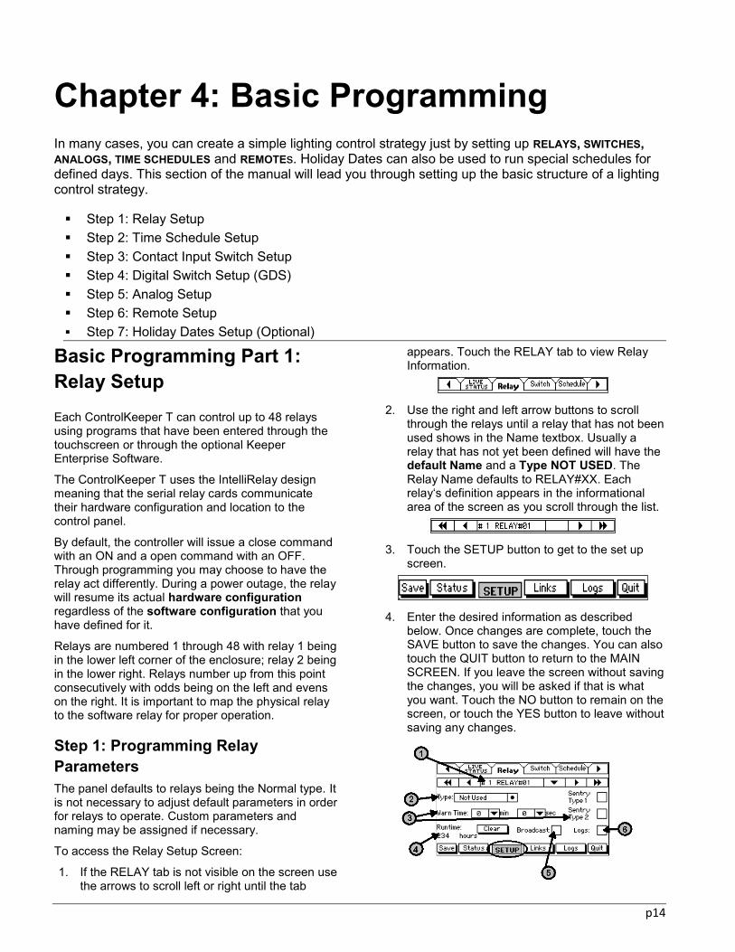
Step 1: Documenting GDS Programming Each button on the GDS Station will be assigned an address using either the onboard GDS Commissioning tool, or the commissioning feature within the Keeper Enterprise or GDS Commissioning Tool software packages. To prepare for this process, you should document each button‘s programming to identify the addressing scheme you will be using. Blank configuration charts that are used in this chapter are available in Appendix B: on page 67.
To fill in the GDS chart:
1. Identify each station in your network by
writing in its location in the facility and what button configuration is on the station. See the chart below for easy identification of your station models.

p25
2. For each station, identify the relays that each
button is going to control.
3. Starting at address 1, assign each button that controls a unique group of relays a unique address. If buttons that belong to two or more different stations are going to control the same group of relays, i.e. 3-way switches, they should be assigned the same button address. This is shown with the buttons assigned to address 6 in the example chart in this section. Because they control the same relay group, they are both assigned to the same address.
4. The ControlKeeper T can be programmed with up to 64 inputs. Any of the 64 inputs can be assigned to any GDS address or hard-wired contact closure switches. In the last column, for each unique address, document which of the 64 inputs will map to which GDS address. (Note that in the example chart: address 6 will be programmed to one input even though it is used for two buttons.) If you have already programmed contact closure switches in your system, you will want to ensure that you use input numbers other than those you are using for your contact closure devices.
Step 2: Programming GDS Switches Once you have determined the addresses you will use, you are ready to begin programming. You will need to first configure the switch BUS type so that it understands a GDS network is connected and then program an input for each GDS address you will be using.
Configuring Switch Bus Type The ControlKeeper T version 5.7.0 and higher can support the current GDS architecture and also contains legacy support for the previous Digita switch model series. Before you can begin commissioning or programming your GDS Switch stations, you will need to ensure that the Switch Bus type is set for the current GDS operation.
1. If the PANEL SETUP tab is not visible on the screen use the arrows to scroll left or right until the tab appears. Touch the tab to view the Panel Setup Screen.
2. If you are not already in the Setup screen, touch
the SETUP button at the bottom of the screen.
3. Make certain that the Switch Bus type field is
set for GDS and press the SAVE button.
If you change the Switch Bus type, you will be prompted to verify you wish to make this change. If you have previously programmed a Digita or GDS switch in the Switch Inputs screens, the address parameters will be overwritten when the Switch Bus field is changed. Please be cautious when changing the Switch Bus type to avoid overwriting your current settings. Review all digital switch addresses if the Switch Bus type is changed.
Configuring basic GDS input programming For each unique address you have assigned in your GDS programming chart, it will be necessary to program an input in the ControlKeeper T. Inputs 1 through 64 may be assigned to any contact closure or GDS address. Refer to your chart you prepared to identify the first input number you are going to program, making sure that you use a unique input # that has not already been programmed for another function.
1. If the SWITCH tab is not visible on the screen use the screen tab arrows to scroll left or right until the Switch Tab appears. Touch the tab to view Switch Information.
2. Use the right and left arrow buttons to scroll
through the list of switches until you see the switch you would like to program.
3. First define the switch on the BASIC SETUP
page. Change the definitions as described below. When you have completed the setup, touch the SAVE button to save the changes.

p26
You can also touch the QUIT button to return to the MAIN SCREEN. If you leave the screen without saving the changes, you will be asked if that is what you want. Touch the NO button to remain on the screen, or touch the YES button to leave without saving any changes.
Field 1: Setting Switch Name
The Switch Name defaults to SWITCH01, SWITCH02, etc. To enter a different Switch Name, touch the down arrow to the right of the default name on the Switch Scrolling list. A touchscreen keypad will appear. Press the characters you want and then touch the Enter button to save the name or numbers. The Switch Name can have a maximum of eight characters. We recommend that you use a unique name that refers to the location of the switch or the function of the load that the switch controls, such as ―2FL HALL‖. Unique names must be used if this switch is going to be controlling relays in another enclosure.
Field 2: Setting Switch Type
There are multiple switch types available. Greengate Digital Switch buttons need to be defined as the GDS Button type. If you do not see the GDS Button type available, please ensure that your Switch Bus Type field in the main Panel Setup tab is set for GDS operation.
Field 3: Setting Switch Commands
The control panel allows you to choose the command to be issued from a switch when it is turned on, and also for when it is turned off. This may affect how the switch works for your application. Your choices are ON, OFF, and NO COMMAND. The CKT defaults to issuing an ON command for the ON and an OFF command for the OFF.
The NO COMMAND selection is most often used when priorities have been used. A NO COMMAND
command at the NONE level of priority can be used to release a higher priority command from this switch without actually changing the relay‘s state. See ―Using ControlKeeper Priorities‖ on page 40 for more information.
Touch the DOT at the right of the ON Command choice box. Each time you touch the dot you will toggle through the list of possible commands. Stop the toggle when the command you want shows on the Command textbox. Do the same to set the OFF command.
Field 4: Setting Switch Priorities
Use the right and left arrows to scroll through the available priority levels until you see the priority level you would like for the command.
Priorities that are available in a basic setup are: NONE, PRIORITY, and MASTER. If you have chosen to use Advanced Programming options, you will have access to several other levels of the MASTER priority: MASTER2, MASTER3, MASTER4, …..MASTER12, MASTER13. See ―Using ControlKeeper Priorities‖ on page 40 for an explanation of MASKS and PRIORITIES.
In most cases, you need only use the three lowest priorities to attain the control levels you need.
Field 5: Setting Switch Timers
A switch can have a timer from 1 to 999 minutes and from 1 to 59 seconds. When the user turns a relay ON with a switch that has a timer the control panel starts the timer running. At the end of the timer period, the control panel will automatically issue an OFF command from this switch to the linked relays. This feature is often used for after-hours overrides.
To set up a Switch Timer, touch the down arrow to the right of the Timer Minutes field. A drop-down touchscreen numeric keypad will appear. Touch the numbers you want, then touch the ENTER button. Do the same for the Timer Seconds field.
Timer Cautions: When you use an input timer, you may need to
provide a NO TIMER MASK or a prioritized schedule to prevent the timer from turning lights off during regular scheduled ON times. See ―Chapter 5: Advanced Programming‖ on page 40 for an explanation of MASKS and PRIORITIES.
When a switch with a timer has been turned ON, only that switch can cancel the timer by sending an OFF command.
Field 6: Setting a Switch to Broadcast
If you have a NETWORK of ControlKeeper T panels, there may be a time when you would like a switch in one panel to control relays in other networked control

p27
panels. You can do this by setting the switch to broadcast onto the network whenever it turns on or off.
To choose to broadcast the switch, touch the checkbox next to the Broadcast option. A checkmark will appear. To remove the broadcast option, touch the checkbox again, and the checkmark will disappear.
A switch that is set to broadcast will send its name and the ON or OFF state across the network wire whenever it is used. You would need to set up a Remote Input with the same name as the original switch in the other panels to receive the broadcast command. Special settings such as masking, priorities, timers, and changes of the commands issued will not broadcast with the switch. These settings, if desired will need to be setup on the remote command. See ―Basic Programming Part 6: Setting up Remotes‖ on page 23 for more information.
Field 7: Setting Switch Logging
Logs are a great tool for troubleshooting your lighting system. When the Log option is selected for a switch, the control panel maintains a listing of each switch actuation, including the switch Name, on or off Status, and the Time and Date of the change.
To choose to log the switch actuations, touch the checkbox next to the Log option. A checkmark will appear. To remove the log option, touch the checkbox again, and the checkmark will disappear.
Field 8: Setting Switch Warn Off
The Warn OFF feature is designed to give a warning to the occupants of an area that the lights are about to go off. The warning will occur only if the controlled relay has been programmed with a warn. If a switch has been linked to multiple relays, some with Warn enabled and some without the warn option, a Switch Warn Off command will only occur with associated relays that have warn times assigned. See ―Field 3: Setting Relay Warn‖ on page 15 for information about relay warning sequences.
To set a switch to initiate the defined relay warning sequence, touch the Warn Off checkbox. A checkmark will appear. Touch the checkbox again to remove the warn feature.
Programming the GDS Advanced Setup Page Once the basic input information is programmed, you will need to access the Advanced Setup page to program the address and LED behavior for a GDS station button.
1. If the SWITCH tab is not visible on the screen use the screen tab arrows to scroll
left or right until the Switch Tab appears. Touch the tab to view Switch Information.
2. Use the right and left arrow buttons to scroll
through the list of switches until you see the switch input number that you wish to program.
3. Access the Switch SETUP page. Make sure
that the switch type is defined for the GDS BUTTON type.
4. Touch the ADVANCED SETUP button to
continue defining the switch.
5. Change the Advanced definitions as
described in the below field descriptions. Once settings are complete, press the SAVE button to save the changes. Proceed on to the next procedure to link the button to the relays it will control.
Field 1: Setting the Button Address
Use the drop down arrow next to the Button Address field to enter the address the selected switch input will operate with. Whenever a button with that address issues a command from the GDS network, this input‘s programming will execute.
Field 2: Setting GDS Button Feedback
Each GDS Button has an LED that will illuminate as an indication of load status. You can choose from two sources for the illumination: Self Feedback and

p28
Feedback from a Relay. Feedback must be set to one or the other for proper operation of the switch. GDS Buttons will issue the command opposite its current LED status, i.e. if the LED is OFF, it will issue an ON command with the next press, if the LED is ON, it will issue an OFF command with the next press. If no feedback is setup, the LED will not illuminate or change states properly to allow both ON and OFF commands to function from the button.
Self Feedback When you choose Self Feedback, the indicator light will track with the last command issued from the switch. The LED will be lit if the switch has issued an ON command and it will be OFF when the switch has issued an OFF command. (This method does not take into account that some other input such as another switch or a time schedule may have turned ON or OFF lights. For instance, if the switch is turned ON, the LED will light. If a time schedule turns off the relays that the switch runs, the LED in the switch will continue to be ON until that switch issues an OFF command.)
To choose this option, touch the Self Feedback check box and a checkmark will appear, activating the Self Feedback Lighted Switch Option. (The Feedback Relay data field will then show ―- -―.) Touch the check box again to de-activate this feature.
Feedback Relay Alternatively, you can choose to have the button indicator show the status of one of the relays controlled by the button. When you choose this option, the indicator light will be ON when the relay is on and OFF when the relay is off. With this method, if another switch or time schedule turns the feedback relay off or on, the switch will reflect the proper status.
Touch the down arrow to the right of the Feedback Relay data field. A drop-down numeric touchscreen keypad will appear. Touch the keypad numbers to enter the relay number that you want for feedback status, then touch the enter button. When you choose Relay Feedback, the Self Feedback option will automatically be deactivated.
When you are programming through the touchscreen, a feedback relay must be assigned from within the same panel that the GDS switch network is wired. With the optional Keeper Enterprise Software, it is possible to have the feedback relay be programmed in another panel. Please contact technical support for further details.
Linking the GDS Button to the Relays it Controls Each programmed switch input can control one, some, or all of the relays in the ControlKeeper enclosure. You Link (or ―tie‖) a switch to a relay through the Switch Links Screen. The IntelliRelay design will indicate when a relay is physically not there by graying out the checkbox.
To link a Relay to a Switch:
1. If the SWITCH tab is not visible on the screen use the arrows to scroll left or right until the tab appears. Touch the tab to view Switch Information.
2. Use the right and left arrow buttons to scroll
through the list of switches until you see the switch that you want to link to relays. Each switch definition appears in the informational area of the screen as you scroll through the list.
3. Touch the LINKS button to get to the screen
for setting up which relays are controlled by this switch.
4. Only relays that are defined as types other
than NOT USED appear on the list of available relays. Touch the check box to the right of each relay that you wish to control with this switch. The scrolling arrows will move the screen up and down to show additional relays. To unlink a relay, touch the checkbox to remove the checkmark.
5. When you have completed the Links touch
the SAVE button to save the changes. You can also touch the QUIT button to return to the MAIN SCREEN. If you leave the screen without saving the changes, you will be asked if that is what you want. Touch the NO

p29
button to remain on the screen, or touch the YES button to leave without saving any changes.
Linking a Switch to Relays in another Enclosure If the wall switch is connected to one controller but needs to control relays in another enclosure, it will be necessary to network the lighting control panels. The wall switch is initially set up as a switch in the panel that it is wired to. Under the basic setup section, it will be necessary to ensure that the BROADCAST option is selected. Please see ―Field 6: Setting a Switch to Broadcast‖ on page 20 for information on this setting. Make note of the switch name including capitalization and punctuation.
In the panel that contains the relays that the switch needs to control, a remote is set up with the same exact name as the wall switch. The relays are then linked to that remote. Please see ―Basic Programming Part 6: Setting up Remotes‖ on page 35 for further details.
The name of the switch and the ON or OFF command is broadcast over the network wire whenever the switch is actuated. Any panel with a remote with the same name will respond accordingly.
Only the name of the switch and the physical ON and OFF command broadcast. Special parameters such as priorities, timers, and warns are local to the panel and do not broadcast. These will need to be set up on the remote command if this logic is desired in the other enclosure.
Step 3: GDS Commissioning – Assigning Button Addresses In this step, you will program the addresses that each button will operate with into the GDS stations. This step is best done at a time when there is not a chance of switch buttons being pressed by occupants in the space.
1. Remove the GDS-I power wiring terminal block from the ControlKeeper T and disconnect the GDS-I phone style communication cable from the panel.
2. Use an Ohm meter to measure for ohms across the CAN-H (White) and CAN-L (Blue) terminals of the GDS-I terminal block. You should get a reading of close to 60ohms. If you get a reading other than this figure, double check that the terminators are in the ‗Termination ON‘ position at the beginning and end devices on the network and that they are placed in the ‗Termination OFF‘ position on remaining devices. Termination jumpers are located on the back of GDS switch stations next to the wiring
terminal block. The GDS-I has a termination jumper next to the wiring terminal block.
(If you do not have an Ohm Meter, visually verify that the termination jumpers are in the ‘Termination ON’ position at the beginning and ending device on the network then proceed to the next step.)
3. Reconnect +24V power wiring and the communication cable to the ControlKeeper T panel verifying that the phone style cable is connected to the port labeled ‗DIGITA‘ in the upper right corner of the board..
4. From the ControlKeeper T touchscreen, If the SWITCH tab is not visible on the screen use the screen tab arrows to scroll left or right until the Switch Tab appears. Touch the tab to view Switch Information.
5. Use the right and left arrow buttons to scroll
through the list of switches until you see the first switch input number assigned to the desired GDS address.
6. Access the Switch SETUP page. Then touch
the ADVANCED SETUP button.
7. In the Advanced Setup page, touch the
COMMISSION button.
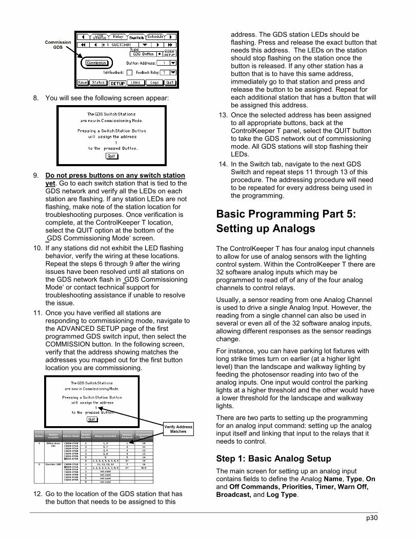
p30
8. You will see the following screen appear:
9. Do not press buttons on any switch station
yet. Go to each switch station that is tied to the GDS network and verify all the LEDs on each station are flashing. If any station LEDs are not flashing, make note of the station location for troubleshooting purposes. Once verification is complete, at the ControlKeeper T location, select the QUIT option at the bottom of the ‗GDS Commissioning Mode‘ screen.
10. If any stations did not exhibit the LED flashing behavior, verify the wiring at these locations. Repeat the steps 6 through 9 after the wiring issues have been resolved until all stations on the GDS network flash in ‗GDS Commissioning Mode‘ or contact technical support for troubleshooting assistance if unable to resolve the issue.
11. Once you have verified all stations are responding to commissioning mode, navigate to the ADVANCED SETUP page of the first programmed GDS switch input, then select the COMMISSION button. In the following screen, verify that the address showing matches the addresses you mapped out for the first button location you are commissioning.
12. Go to the location of the GDS station that has
the button that needs to be assigned to this
address. The GDS station LEDs should be flashing. Press and release the exact button that needs this address. The LEDs on the station should stop flashing on the station once the button is released. If any other station has a button that is to have this same address, immediately go to that station and press and release the button to be assigned. Repeat for each additional station that has a button that will be assigned this address.
13. Once the selected address has been assigned to all appropriate buttons, back at the ControlKeeper T panel, select the QUIT button to take the GDS network out of commissioning mode. All GDS stations will stop flashing their LEDs.
14. In the Switch tab, navigate to the next GDS Switch and repeat steps 11 through 13 of this procedure. The addressing procedure will need to be repeated for every address being used in the programming.
Basic Programming Part 5: Setting up Analogs The ControlKeeper T has four analog input channels to allow for use of analog sensors with the lighting control system. Within the ControlKeeper T there are 32 software analog inputs which may be programmed to read off of any of the four analog channels to control relays.
Usually, a sensor reading from one Analog Channel is used to drive a single Analog Input. However, the reading from a single channel can also be used in several or even all of the 32 software analog inputs, allowing different responses as the sensor readings change.
For instance, you can have parking lot fixtures with long strike times turn on earlier (at a higher light level) than the landscape and walkway lighting by feeding the photosensor reading into two of the analog inputs. One input would control the parking lights at a higher threshold and the other would have a lower threshold for the landscape and walkway lights.
There are two parts to setting up the programming for an analog input command: setting up the analog input itself and linking that input to the relays that it needs to control.
Step 1: Basic Analog Setup The main screen for setting up an analog input contains fields to define the Analog Name, Type, On and Off Commands, Priorities, Timer, Warn Off, Broadcast, and Log Type.

p31
1. If the Analog Tab is not visible on the screen use the arrows to scroll left or right until the Analog Tab appears. Touch the tab to view Analog Information.
2. When you set up a new input, use the right
and left arrow buttons to scroll through the analogs until you see an analog with the Type “NOT USED”. Each analog‘s definition appears in the informational area of the screen as you scroll through the list.
3. Define the analog as described below. When
you have completed this basic setup, touch the ADV. SETUP Button to move to the Advanced Setup Screen. If you are not prepared to enter advanced parameters for this input, you can touch the SAVE button to save the basic information you have just entered. You can also touch the QUIT button to return to the MAIN SCREEN. If you leave the screen without saving the changes, you will be asked if that is what you want. Touch the NO button to remain on the screen, or touch the YES button to leave without saving any changes.
Field 1: Setting Analog Name To enter a new Analog Name, press the down arrow next to the alphanumeric data entry field and a touchscreen keypad will appear. You can enter up to 8 alphanumeric characters. Press the characters you want and then touch the Enter button to save the name or numbers. The SHIFT button takes you back and forth between the upper case and lower case keypads. Touch the PUNCTUATION button to see the punctuation keypads. We suggest you choose a name indicative of the location or of the function of the sensor.
Field 2: Setting Analog Type The Analog Type can be Photocell, Custom or Not Used. To enter an Analog Type, touch the DOT to the right of the type textbox. Each time you touch the dot, you will toggle through the available types:
PHOTOCELL, CUSTOM and NOT USED. Stop when you see the Type you want.
The Photocell type is used for an interior or exterior analog photosensor. Through programming, you will tell the ControlKeeper T what the range of the photosensor is. Refer to the installation instructions that came with your photosensor to determine what the range definition should be.
The Custom type is used for a 0 - 10 Volt sensor that is not a photosensor. You may set this up as a Custom analog. You set the sensor range and other control options in the Advanced Setup Screen as defined later in this section. Please refer to the information provided with your sensor for information on the sensor‘s range and expected voltage.
The Not Used selection is used if there is no analog input wired into this channel. If an analog channel is set up as any other type than Not Used and nothing is wired into the channel, erroneous commands may be sent due to false readings from the channels.
Field 3: Setting Analog Commands The control panel allows you modify the way a sensor works by changing the command that is issued when the sensor reading calls for an On and also for when the reading calls for an Off. Your choices are ON, OFF, and NO COMMAND. The CKT defaults to issuing an ON command for the ON and an OFF command for the OFF.
The NO COMMAND selection is most often used with priorities. A NO COMMAND command at the NONE level of priority can be used to release a higher priority command from this analog without actually changing the relay‘s state. See ―Using ControlKeeper Priorities‖ on page 40 for more information.
Touch the DOT at the right of the ON Command choice box. Each time you touch the dot you will toggle through the list of possible commands. Stop the toggle when the command you want shows on the Command textbox.
Repeat this procedure to set the OFF command.
Field 4: Setting Analog Priorities You can assign a priority level to an analog input command. The priority level affects how the input interacts with other inputs to control the lighting.
To set up a priority level for the input, use the right and left arrows to scroll through the available priority levels until you see the priority level you would like for the command.
Priorities that are available in a basic setup are: NONE, PRIORITY, and MASTER. If you have chosen to use Advanced Programming options, you will have access to several other levels of the

p32
MASTER priority: MASTER2, MASTER3, MASTER4, …..MASTER12, MASTER13. See ―Using ControlKeeper Priorities‖ on page 40 for an explanation of PRIORITIES.
In most cases, you need only use the three lowest priorities to attain the control levels you need.
Field 5: Setting Analog Timers Although it is unusual for an analog to have a timer associated with it, it is possible to set this up if desired. A timer is a specified period of time assigned to an analog input ON command after which an OFF command will be automatically issued. While the timer is running, it protects the lighting from being turned off by another input of the same priority.
An analog can have a timer from 1 to 999 minutes and from 1 to 59 seconds. When the photosensor turns a relay ON with a timer the control panel starts the timer running. At the end of the timer period, the control panel will automatically issue an OFF command from this analog to the linked relays, regardless of the analog reading.
To set up an analog timer, touch the down arrow to the right of the Timer Minutes field. A drop-down touchscreen numeric keypad will appear. Touch the numbers you want, then touch the ENTER button. Do the same for the Timer Seconds field.
Timer Cautions:
When you use an input timer, you may need to provide a NO TIMER MASK or a prioritized schedule to prevent the timer from turning lights off during regular scheduled ON times. See ―Chapter 5: Advanced Programming‖ on page 40 for an explanation of using MASKS and PRIORITIES.
When an analog with a timer has been turned ON, only that analog can cancel the timer by sending an OFF command.
Field 6: Setting Up Analog Warn Off The Warn OFF feature is designed to give a warning to the occupants of an area that the lights are about to go off. The warning will occur only if the controlled relay has been programmed with a Warn. If an analog has been linked to multiple relays, some with Warn enabled and some without the warn option, an Analog Warn Off command will only occur with associated relays that have warn times assigned. See ―Field 3: Setting Relay Warn‖ on page 15 for information about relay warning sequences.
To set an analog to initiate the defined relay warning sequence, touch the Warn Off checkbox. A checkmark will appear. Touch the checkbox again to remove the warn option.
Field 7: Setting the Broadcast Option If you enable the Broadcast Option for an analog input, the control panel will broadcast the new On or Off Command onto the network when the input reading passes through the threshold set for control of the associated lighting, This allows a single photosensor input wired into one control panel to control many relays in many lighting control panels.
The information that broadcasts is name of the analog input and the ON or OFF command. Modification of the command state in the analog programming as well as priorities, timers, mask and warn settings will not be broadcast. These must be set up at the Remote Input in the receiving panel.
To set an analog to broadcast, touch the Broadcast checkbox. A checkmark will appear. Touch the checkbox again to remove the broadcast feature.
It will be necessary to set up the remote panel with a Remote Command to accept the analog broadcast feature.
Field 8: Setting Analog Logging Logs are a great tool for troubleshooting your lighting system. When the Log option is selected for an analog, the control panel maintains a history of either the commands issued by the analog or of its readings. You have three options for logging an analog: logging the Reading, the change of State, or leaving it at the None option.
If you choose to log the Reading, the ControlKeeper records the time, date, and analog reading with every 5% change in value that it senses. This information can be extremely useful when you set up thresholds, although it is very memory intensive. Once you have set up the threshold for the analog input and verified the results, you can change the log type to State.
If you choose to log the State, the ControlKeeper records the reading, time and date whenever the analog value passes through its assigned threshold. It also logs the command it issued. Once thresholds have been set, this method of logging still allows you to view the data without the extensive log files.
If you leave the choice at None, the analog input will not log.
To choose to log the analog actuations, touch the DOT at the right of the Log choice box. Each time you touch the dot you will toggle through the list of log types. Stop the toggle when the type that you want shows on the Log textbox.
Step 2: Setting Analog Parameters The Advanced Analog Settings screen for an analog input is where you define the Channel into which the sensor is wired, define the Thresholds used to control the lighting, set the upper and lower
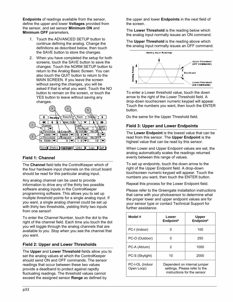
p33
Endpoints of readings available from the sensor, define the upper and lower Voltages provided from the sensor, and set sensor Minimum ON and Minimum OFF parameters.
1. Touch the ADVANCED SETUP button to continue defining the analog. Change the definitions as described below, then touch the SAVE button to store the changes.
2. When you have completed the setup for both screens, touch the SAVE button to save the changes. Touch the NORM SETUP button to return to the Analog Basic Screen. You can also touch the QUIT button to return to the MAIN SCREEN. If you leave the screen without saving the changes, you will be asked if that is what you want. Touch the NO button to remain on the screen, or touch the YES button to leave without saving any changes.
Field 1: Channel The Channel field tells the ControlKeeper which of the four hardware input channels on the circuit board should be read for this particular analog input.
Any analog channel can be used to provide information to drive any of the thirty two possible software analog inputs in the ControlKeeper programming software. This allows you to set up multiple threshold points for a single analog input. If you want, a single analog channel could be set up with thirty two thresholds, yielding thirty two inputs from one sensor!
To enter the Channel Number, touch the dot to the right of the channel field. Each time you touch the dot you will toggle through the analog channels that are available to you. Stop when you see the channel that you want.
Field 2: Upper and Lower Thresholds The Upper and Lower Threshold fields allow you to set the analog values at which the ControlKeeper should send ON and OFF commands. The sensor readings that occur between these two values provide a deadband to protect against rapidly fluctuating readings. The threshold values cannot exceed the assigned sensor Range as defined by
the upper and lower Endpoints in the next field of the screen.
The Lower Threshold is the reading below which the analog input normally issues an ON command.
The Upper Threshold is the reading above which the analog input normally issues an OFF command.
To enter a Lower threshold value, touch the down arrow to the right of the Lower Threshold field. A drop-down touchscreen numeric keypad will appear. Touch the numbers you want, then touch the ENTER button.
Do the same for the Upper Threshold field.
Field 3: Upper and Lower Endpoints The Lower Endpoint is the lowest value that can be read from this sensor. The Upper Endpoint is the highest value that can be read by this sensor.
When Lower and Upper Endpoint values are set, the analog automatically scales the readings returned evenly between this range of values.
To set up endpoints, touch the down arrow to the right of the Upper Endpoint field. A drop-down touchscreen numeric keypad will appear. Touch the numbers you want, then touch the ENTER button.
Repeat this process for the Lower Endpoint field.
Please refer to the Greengate installation instructions that came with your photosensor to determine what the proper lower and upper endpoint values are for your sensor type or contact Technical Support for further assistance.
Model # Lower Endpoint*
Upper Endpoint*
PC-I (Indoor) 0 100
PC-O (Outdoor) 0 250
PC-A (Atrium) 2 1000
PC-S (Skylight) 10 2000
PC-I-OL (Indoor Open Loop)
Dependent on internal jumper settings. Please refer to the instructions for the sensor

p34
*These ranges were valid for these sensor models at the time of the printing of this manual. Please cross reference the installation instructions provided with your sensor to verify that there have not been any changes.
Field 4: Upper and Lower Voltage The CKT can accommodate output voltages between 0.0 and10.0 Volts DC in the analog channels. If a sensor outputs more than 10.0 volts or less than 0.0 volts it cannot be used.
The Up Voltage is the highest output voltage that the sensor provides. The Lo Voltage is the lowest output voltage that the sensor provides. Please refer to the installation instructions for your sensor to determine the upper and lower voltages for that sensor. (By default, if the photocell type has been chosen, the Lo Voltage of 1.0 and Hi Voltage will be 10.0).
Model # Lower Voltage* Upper Voltage*
PC-I (Indoor) 1 10
PC-O (Outdoor) 1 10
PC-A (Atrium) 1 10
PC-S (Skylight) 1 10
PC-I-OL (Indoor Open Loop)
0 10
*These voltages were valid for these sensor models at the time of the printing of this manual. Please cross reference the installation instructions provided with your sensor to verify that there have not been any changes.
To enter the Up Voltage, touch the down arrow to the right of the voltage field. A numeric keypad will appear. The range for the type of sensor chosen will appear in decimal form at the left of the keypad screen.
As you touch a numeric key, its value will be entered in the decimal portion of the display. With each further keystroke, the value will ―roll‖ to the left. To enter a voltage of 1 V, you must enter 1 followed by a 0. The display will show 1.0. Press the ENTER key.
Repeat this procedure for the Lo Voltage field.
Field 5: Setting Analog Minimum ON and Minimum OFF The Minimum On and Minimum Off fields allow you to set minimum time limits between the ON and OFF states. This can prevent cycling of the lighting if the analog input goes through a rapid change in readings. The field cannot exceed 999 minutes.
To set the Minimum ON time, touch the down arrow to the right of the data field. A drop-down touchscreen numeric keypad will appear. Touch the numbers you want, then touch the ENTER button.
To set the Minimum OFF time, touch the down arrow to the right of the data field. A drop-down touchscreen numeric keypad will appear. Touch the numbers you want, then touch the ENTER button.
For instance, if a Minimum OFF time of 10 minutes has been entered in to the Minimum OFF field, when the photosensor triggers an off command, it starts the 10 minute timer running. Until this timer expires, the photosensor cannot issue another ON command to the lights. Once the 10 minutes has expired, if the photosensor is calling for the lights to go on, they will respond on.
Step 3: Linking the Analog to the Controlled Relays Each Analog Input can control one, some, or all of the relays in the ControlKeeper enclosure. You Link (or ―tie‖) an Analog Input to a relay through the Analog Links Screen. Please note that only the relays that are set as types other than NOT USED will be shown in the links screen.
To link a Relay to an Analog:
1. If the ANALOG tab is not visible on the screen use the arrows to scroll left or right until the tab appears. Touch the tab to view Analog Information.
2. Use the right and left arrow buttons to scroll
through the list of analogs until you see the analog that you want to link to relays. Each analog definition appears in the informational
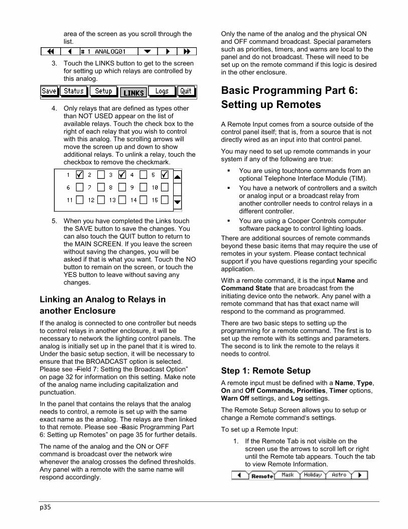
p35
area of the screen as you scroll through the list.
3. Touch the LINKS button to get to the screen
for setting up which relays are controlled by this analog.
4. Only relays that are defined as types other
than NOT USED appear on the list of available relays. Touch the check box to the right of each relay that you wish to control with this analog. The scrolling arrows will move the screen up and down to show additional relays. To unlink a relay, touch the checkbox to remove the checkmark.
5. When you have completed the Links touch
the SAVE button to save the changes. You can also touch the QUIT button to return to the MAIN SCREEN. If you leave the screen without saving the changes, you will be asked if that is what you want. Touch the NO button to remain on the screen, or touch the YES button to leave without saving any changes.
Linking an Analog to Relays in another Enclosure If the analog is connected to one controller but needs to control relays in another enclosure, it will be necessary to network the lighting control panels. The analog is initially set up in the panel that it is wired to. Under the basic setup section, it will be necessary to ensure that the BROADCAST option is selected. Please see ―Field 7: Setting the Broadcast Option‖ on page 32 for information on this setting. Make note of the analog name including capitalization and punctuation.
In the panel that contains the relays that the analog needs to control, a remote is set up with the same exact name as the analog. The relays are then linked to that remote. Please see ―Basic Programming Part 6: Setting up Remotes‖ on page 35 for further details.
The name of the analog and the ON or OFF command is broadcast over the network wire whenever the analog crosses the defined thresholds. Any panel with a remote with the same name will respond accordingly.
Only the name of the analog and the physical ON and OFF command broadcast. Special parameters such as priorities, timers, and warns are local to the panel and do not broadcast. These will need to be set up on the remote command if this logic is desired in the other enclosure.
Basic Programming Part 6: Setting up Remotes
A Remote Input comes from a source outside of the control panel itself; that is, from a source that is not directly wired as an input into that control panel.
You may need to set up remote commands in your system if any of the following are true:
You are using touchtone commands from an optional Telephone Interface Module (TIM).
You have a network of controllers and a switch or analog input or a broadcast relay from another controller needs to control relays in a different controller.
You are using a Cooper Controls computer software package to control lighting loads.
There are additional sources of remote commands beyond these basic items that may require the use of remotes in your system. Please contact technical support if you have questions regarding your specific application.
With a remote command, it is the input Name and Command State that are broadcast from the initiating device onto the network. Any panel with a remote command that has that exact name will respond to the command as programmed.
There are two basic steps to setting up the programming for a remote command. The first is to set up the remote with its settings and parameters. The second is to link the remote to the relays it needs to control.
Step 1: Remote Setup A remote input must be defined with a Name, Type, On and Off Commands, Priorities, Timer options, Warn Off settings, and Log settings.
The Remote Setup Screen allows you to setup or change a Remote command‘s settings.
To set up a Remote Input:
1. If the Remote Tab is not visible on the screen use the arrows to scroll left or right until the Remote tab appears. Touch the tab to view Remote Information.

p36
2. Use the right and left arrow buttons to scroll through the remotes until you see a remote that has not yet been defined. Each remote‘s definition appears in the informational area of the screen as you scroll through the list. An unused remote input will have the Type “NOT USED‖.
3. Enter the Remote parameters as described
below. When you have completed the setup, touch the SAVE button to store the changes. You can also touch the QUIT button to return to the MAIN SCREEN. If you leave the screen without saving the changes, you will be asked if that is what you want. Touch the NO button to remain on the screen, or touch the YES button to leave without saving any changes.
Field 1: Setting Remote Name The external device that initiates the Remote Command will broadcast it over the network as a Name and an ON/OFF State. The listening ControlKeeper matches the broadcast command name against the list of names that have been defined as Remote Inputs for the panel. If it finds a match, it will command the relays that have been linked to that Remote Name. The Remote Name has up to 8 characters that must match exactly the name of the broadcasted command.
To enter a new Remote Name, press the down arrow next to the alphanumeric data entry field and a touchscreen keypad will appear. Press the characters you want and then touch the Enter button to save the name or numbers. The SHIFT button takes you back and forth between the upper case and lower case keypads. Touch the PUNCTUATION button to see the punctuation keypads.
Setting up Remote Names is crucial to the proper operation of your lighting system. Please see the steps below based on the type of remote command that you are trying to set up.
Switch, an Analog or Relay Command from
Another Panel
To set up the remote name from a broadcast switch, analog or relay in another panel, match the name exactly to the originating switch, analog or relay.
Telephone Interface Module Command
A Telephone Interface Module Remote command name must start out with the capital letters ―TIM‖. Following these letters will be the numeric code that the user will input through a touch Tone telephone to control the lighting. The numeric code can contain from 1 to 5 numbers. For instance, if you programmed a remote named TIM012 into the controller, the user would need to input the TIM code ―012‖ when prompted for this information by the TIM.
DMX Gateway Command
The DMX Gateway issues TIM commands onto the network wire. For the TIM Codes available for your DMX Gateway, please refer to the instructions for your unit.
To setup these commands in the controller, the remote name must start out with the capital letters ―TIM‖. The numeric code afterwards must be 1 through 512 (no leading zeros for single digit numbers).
Cooper Controls Software Command
Optional software packages such as VisionSwitch, VisionTouch or Keeper Enterprise Software, etc… may be used with the system. These software packages allow remote commands to be issued from computers that have been tied into the lighting system. If using these packages to send commands, make certain to exactly match the Remote Name to the name that each VisionSwitch or VisionTouch button will be sending. If Keeper Enterprise Software is being used, this software should be used to set up the remote name fields.
Field 2: Setting Remote Type The Remote Type can be TIM, Switch, or Not Used. All commands except a broadcast switch or analog command should be set up as a TIM type for proper operation. Broadcast switches and analogs should be set up as a SWITCH type.
To enter a Remote Type, touch the DOT to the right of the type textbox. Each time you touch the dot, you will toggle through the three available types: NOT USED, TIM, and SWITCH. Stop when you see the Type you want.
Field 3: Setting Remote Commands The control panel allows you to choose the command to be issued from a remote when it is turned on, and also for when it is turned off. This may affect how the remote works for your application. Your choices are ON, OFF, and NO COMMAND.

p37
The CKT defaults to issuing an ON command for the ON and an OFF command for the OFF.
The NO COMMAND selection is most often used with priorities. A NO COMMAND command at the NONE level of priority can be used to release a higher priority command from this remote without actually changing the relay’s state. See ―Using ControlKeeper Priorities‖ on page 40 for more information.
Touch the DOT at the right of the ON Command choice box. Each time you touch the dot you will toggle through the list of possible commands. Stop the toggle when the command you want shows on the Command textbox.
Do the same to set the OFF command.
Field 4: Setting Remote Priorities Use the right and left arrows to scroll through the available priority levels until you see the priority level you would like for the command.
Priorities that are available in a basic setup are: NONE, PRIORITY, and MASTER. If you have chosen to use Advanced Programming options, you will have access to several other levels of the MASTER priority: MASTER2, MASTER3, MASTER4, …..MASTER12, MASTER13. See ―Using ControlKeeper Priorities‖ on page 40 for an explanation of MASKS and PRIORITIES.
In most cases, you need only use the three lowest priorities to attain the control levels you need.
Field 5: Setting Remote Timers A remote can have a timer from 1 to 999 minutes and from 1 to 59 seconds. When the user turns a relay ON from this remote with a timer the control panel starts the timer running. At the end of the timer period, the control panel will automatically issue an OFF command from this remote to the linked relays. This feature is often used for after-hours overrides.
To set up a Remote Timer, touch the down arrow to the right of the Timer Minutes field. A drop-down touchscreen numeric keypad will appear. Touch the numbers you want, then touch the ENTER button. Do the same for the Timer Seconds field.
Timer Cautions: When you use an input timer, you may need to
provide a NO TIMER MASK or a prioritized schedule to prevent the timer from turning lights off during regular scheduled ON times. See ―Chapter 5: Advanced Programming‖ on page 40 for an explanation of using MASKS and PRIORITIES.
When a remote with a timer has been turned ON, only that remote can cancel the timer by sending an OFF command.
Field 6: Setting Up Remote Warn Off The Warn OFF feature is designed to give a warning to the occupants of an area that the lights are about to go off. The warning will occur only if the controlled relay has been programmed with a warn. If a remote has been linked to multiple relays, some with Warn enabled and some without the warn option, a Remote Warn Off command will only occur with associated relays that have warn times assigned. See ―Field 3: Setting Relay Warn‖ on page 15 for information about relay warning sequences.
To set a remote to initiate the defined relay warning sequence, touch the Warn Off checkbox. A checkmark will appear. Touch the checkbox again to remove the warn option.
Field 7: Setting Remote Logging Logs are a great tool for troubleshooting your lighting system. When the Log option is selected for a remote, the control panel maintains a listing of each remote that has been issued. The log entry includes the remote Name, on or off Status, and the Time and Date of the change.
To choose to log the remote actuations, touch the checkbox next to the Log option. A checkmark will appear. To remove the log option, touch the checkbox again, and the checkmark will disappear.
Step 2: Linking the Remote to The Relays It Controls Each remote can control one, some, or all of the relays in the ControlKeeper enclosure. You Link (or ―tie‖) a remote to a relay through the Remote Links Screen. Please note that only the relays that are set up to types other than NOT USED will be shown in the links screen.
To link a Relay to a Remote:
1. If the REMOTE tab is not visible on the screen use the arrows to scroll left or right until the tab appears. Touch the tab to view Remote Information.
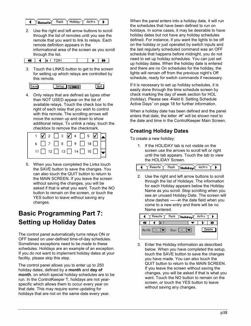
p38
2. Use the right and left arrow buttons to scroll
through the list of remotes until you see the remote that you want to link to relays. Each remote definition appears in the informational area of the screen as you scroll through the list.
3. Touch the LINKS button to get to the screen
for setting up which relays are controlled by this remote.
4. Only relays that are defined as types other
than NOT USED appear on the list of available relays. Touch the check box to the right of each relay that you wish to control with this remote. The scrolling arrows will move the screen up and down to show additional relays. To unlink a relay, touch the checkbox to remove the checkmark.
5. When you have completed the Links touch
the SAVE button to save the changes. You can also touch the QUIT button to return to the MAIN SCREEN. If you leave the screen without saving the changes, you will be asked if that is what you want. Touch the NO button to remain on the screen, or touch the YES button to leave without saving any changes.
Basic Programming Part 7: Setting up Holiday Dates The control panel automatically turns relays ON or OFF based on user-defined time-of-day schedules. Sometimes exceptions need to be made to these schedules. Holidays are an example of an exception. If you do not want to implement holiday dates at your facility, please skip this step.
The control panel allows you to enter up to 250 holiday dates, defined by a month and day of month, on which special holiday schedules are to be run. In the ControlKeeper T, holidays are not year-specific which allows them to occur every year on that date. This may require some updating for holidays that are not on the same date every year.
When the panel enters into a holiday date, it will run the schedules that have been defined to run on holidays. In some cases, it may be desirable to have holiday dates but not have any holiday schedules defined. For instance, if you want the lights to be off on the holiday or just operated by switch inputs and the last regularly scheduled command was an OFF schedule that happens before midnight, you do not need to set up holiday schedules. You can just set up holiday dates. When the holiday date is entered and there are no On schedules for the holiday, the lights will remain off from the previous night‘s Off schedule, ready for switch commands if necessary.
If it is necessary to set up holiday schedules, it is easily done through the time schedule screen by check marking the day of week section for HOL (holiday). Please see ―Field 6: Setting Schedule Active Days‖ on page 18 for further information.
When a holiday date has been defined and the panel enters that date, the letter ―H‖ will be shown next to the date and time in the ControlKeeper Main Screen.
Creating Holiday Dates To create a new holiday:
1. If the HOLIDAY tab is not visible on the screen use the arrows to scroll left or right until the tab appears. Touch the tab to view the HOLIDAY Screen.
2. Use the right and left arrow buttons to scroll
through the list of Holidays. The information for each Holiday appears below the Holiday Name as you scroll. Stop scrolling when you see an unused Holiday Date. The screen will show dashes ―—― in the date field when you come to a new entry and there will be no Name entered.
3. Enter the Holiday information as described
below. When you have completed the setup, touch the SAVE button to save the changes you have made. You can also touch the QUIT button to return to the MAIN SCREEN. If you leave the screen without saving the changes, you will be asked if that is what you want. Touch the NO button to remain on the screen, or touch the YES button to leave without saving any changes.

p39
Field 1: Setting Up the Holiday Name It is not necessary to change the holiday name from the default, however it does make it easier to administer Holidays if each holiday has a meaningful name, such as ―NEW YEAR‖.
To change the holiday name, press the down arrow next to the alphanumeric data entry field and a touchscreen keypad will appear. Press the characters you want and then touch the Enter button to save the name or numbers. The SHIFT button takes you back and forth between the upper case and lower case keypads. Touch the PUNCTUATION button to see the punctuation keypads.
Field 2: Setting up the Holiday Date The control panel allows you to enter up to 32 holiday dates, defined by a month and day of month.
Touch the down arrow next to the Month. A drop down numeric keypad will appear. Touch the numbers you want, then touch the ENTER button. The HI and LOW fields indicate the valid range of numbers for this input field. If you enter a number outside the valid range, the control panel will beep and not let you proceed.
Repeat this process for the Day of Month.
p40
Chapter 5: Advanced Programming In some cases, you may need additional programming to achieve a more in-depth lighting application. This section of the manual will lead you through the concept of priorities in the ControlKeeper System. In addition, we will introduce the concept of masking as well as show you how to set up masks in the ControlKeeper system. This section contains information about the following:
Using Priorities in the ControlKeeper System Using Masking in the ControlKeeper System
There are certain times when the basic programming steps may not achieve the desired application. In some instances you may wish to customize programming to prevent or allow specific commands to occur. In the ControlKeeper system, customization is done through the use of Priorities and Masks.
Using ControlKeeper Priorities Priorities establish a hierarchy of control in the lighting control strategy, allowing for customization of the interactions of the controls within the system. Priorities can be assigned to any input command that controls a relay.
While priorities are extremely powerful, caution should be used in implementing them. It is possible to effectively ‗lock out‘ system functions if priorities are used improperly.
Touchscreen or onboard panel relay override commands and Manual Network Commands will force the relay to the commanded state and to the lowest priority. This will temporarily allow any input to control the relay until the next command occurs.
Command Priority Levels There are fifteen levels of priority in the ControlKeeper system. The 15 priority levels in descending order are:
1. Master 13 9. Master 5 2. Master 12 10. Master 4 3. Master 11 11. Master 3 4. Master 10 12. Master 2 5. Master 9 13. Master 6. Master 8 14. Priority 7. Master 7 15. None 8. Master 6
Each ControlKeeper relay‘s active command will be determined by the order it was received and by the priority level. The input at the highest priority level will maintain control of the relay. If two inputs have the same level of priority and both have commanded
the same relay, the active command will be the command that was received last.
Input commands that are at lower priority levels than the active command will not be processed until the higher level priority command is released.
If all input commands are left at the same level of priority, the system becomes ‗event driven‘ meaning that commands will be obeyed in the order that they are received.
Relinquishing a Command In order to release a command from a higher priority level, it will be necessary to have the input that issued the higher priority command relinquish its control.
In the ControlKeeper system, a priority can only be relinquished by the input that issued the original command. An input is seen as having alternate states, i.e. ON command, and an OFF command. If the ON command is programmed to issue a priority other than ‗none‘, the OFF command should be programmed to issue a ‗none‘ priority to allow relinquish of control.
Time schedules issue a single command. For this reason, schedules are able to relinquish each other, i.e. a MASTER ON schedule would be relinquished by a NONE OFF schedule
When control is relinquished from a higher priority input, the ControlKeeper relay‘s active command will be determined based on the next highest priority input that is active.
Timer Priority In many installations, switch inputs are given timers to allow for after-hours overrides that automatically expire. This prevents the lighting from being left on if the last person neglects to use the switch to turn lighting off and the schedule off period has already processed (and been overridden) for the evening.
When a timer is running, it exerts a ½ step priority up from the priority that is configured for the ON command. Only the input that issued the timer will be

p41
able to cancel the timer‘s command and relinquish this priority before the timer finishes counting down.
Putting Priorities into Practice One use of priorities is highlighted in the following example: Our facility has a fire alarm system which needs to issue a command through a dry contact closure. When an alarm occurs, the emergency lighting needs to turn on and remain on regardless of programmed state. Once the alarm is released, the lighting needs to resume its scheduled state. Other normal inputs are time schedule and switch input commands.
Programming
When the facility is in normal operation mode, the switch inputs and time schedules operate in an ‗event driven‘ mode; each command is obeyed as it is received.
When the facility is in alarm mode, the ‗Master‘ priority prevents the other inputs from functioning. When the alarm mode is relinquished, the other inputs ‗Priority‘ level takes precedence over the ‗None‘ priority of the off command. Whatever switch or time schedule input last issued a command will maintain control of the relay‘s commanded state.
Setting Priorities in the ControlKeeper T Priorities can be assigned to commands that come from switches, analogs, remotes or time schedules. The priority level of the command affects how the switch, analog, remote or time schedule will interact with other inputs to control the lighting as shown in the previous examples.
Notes on Setting Switch, Analog and Remote Input Priorities When a switch, analog or remote input issues a command with a priority higher than the relay‘s current priority, it takes control of the relay until it releases control or until an equal or higher level command is issued from another input.
You release the input control by having it issue the opposite command with a NONE priority. If you want the relay to stay in the commanded state and just release control you can program the input to issue the opposite command as a NO COMMAND at the NONE priority. You set priority levels for an input at the SETUP screen for that input. See ―Field 5:
Setting Schedule Priority‖ on page 17, ―Field 4: Setting Switch Priorities‖ on page 20, ―Field 4: Setting Analog Priorities‖ on page 31 and ―Field 4: Setting Remote Priorities‖ on page 85 for information on setting up priorities on schedules, switches, analogs and remotes.
Notes on Setting Time Schedule Priorities You assign a priority to a Time Schedule in the SETUP screen for the schedule. When a time schedule issues a command with a priority higher than the relay‘s current priority, it takes control of the relay until it releases control or until an equal or higher level command is issued from another input.
You release the time schedule control by setting up another schedule for the opposite command with a NONE priority. If you want the relay to stay in the commanded state and just release the priority control you can program the releasing schedule to issue a NO COMMAND at the NONE priority. If you want to change the state of the relay as well as release control, you program the releasing schedule to issue the opposite command at the NONE priority.
Cautions on Using Priorities While Priorities are extremely powerful and useful, sometimes it can be difficult to see how multiple priorities interact and to see the effect these priorities may have on the lighting system control. They should be used with caution.
For instance, let us say that you set up a command to be at the MASTER2 level for both the ON and the OFF commands from a wall switch. When that switch turns off, the priority level is MASTER2. When that switch turns on, the priority level is still MASTER2. Commands from Time Schedules, Remotes, or other Switches with lower levels of priority will not be able to affect the relay(s) under control of that wall switch.
If you create too many MASTER and PRIORITY commands it might confuse your application. To
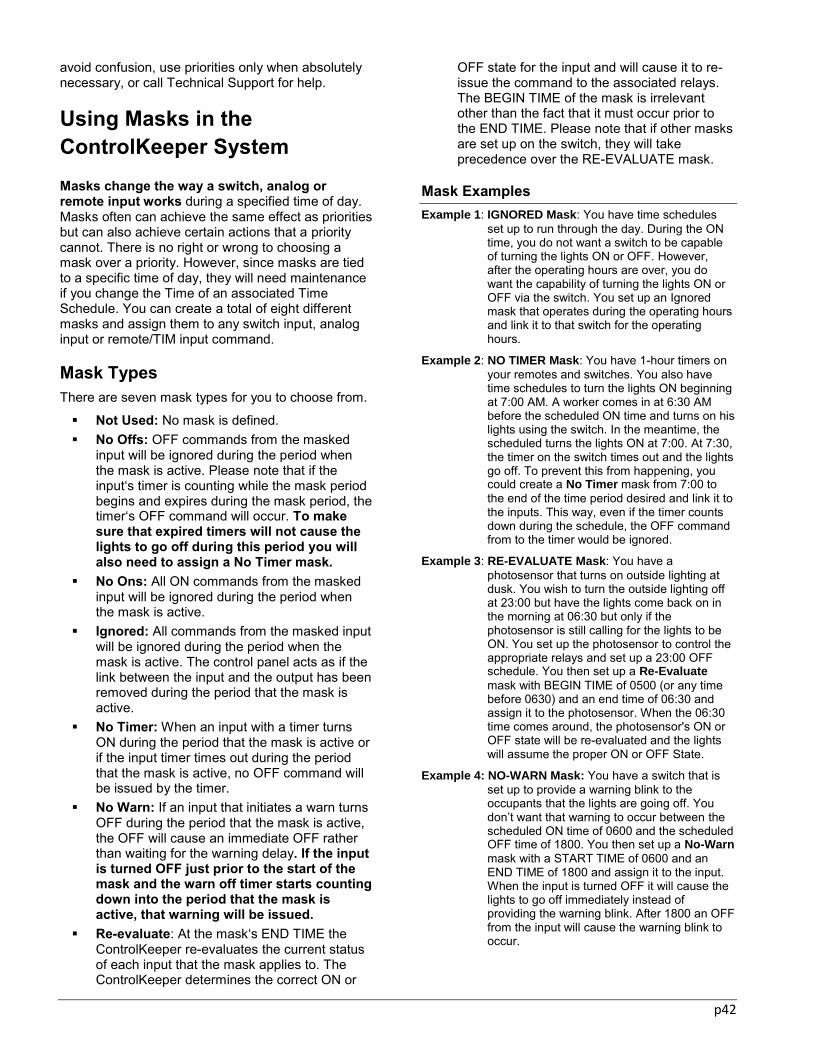
p42
avoid confusion, use priorities only when absolutely necessary, or call Technical Support for help.
Using Masks in the ControlKeeper System Masks change the way a switch, analog or remote input works during a specified time of day. Masks often can achieve the same effect as priorities but can also achieve certain actions that a priority cannot. There is no right or wrong to choosing a mask over a priority. However, since masks are tied to a specific time of day, they will need maintenance if you change the Time of an associated Time Schedule. You can create a total of eight different masks and assign them to any switch input, analog input or remote/TIM input command.
Mask Types There are seven mask types for you to choose from.
Not Used: No mask is defined. No Offs: OFF commands from the masked
input will be ignored during the period when the mask is active. Please note that if the input‘s timer is counting while the mask period begins and expires during the mask period, the timer‘s OFF command will occur. To make sure that expired timers will not cause the lights to go off during this period you will also need to assign a No Timer mask.
No Ons: All ON commands from the masked input will be ignored during the period when the mask is active.
Ignored: All commands from the masked input will be ignored during the period when the mask is active. The control panel acts as if the link between the input and the output has been removed during the period that the mask is active.
No Timer: When an input with a timer turns ON during the period that the mask is active or if the input timer times out during the period that the mask is active, no OFF command will be issued by the timer.
No Warn: If an input that initiates a warn turns OFF during the period that the mask is active, the OFF will cause an immediate OFF rather than waiting for the warning delay. If the input is turned OFF just prior to the start of the mask and the warn off timer starts counting down into the period that the mask is active, that warning will be issued.
Re-evaluate: At the mask‘s END TIME the ControlKeeper re-evaluates the current status of each input that the mask applies to. The ControlKeeper determines the correct ON or
OFF state for the input and will cause it to re-issue the command to the associated relays. The BEGIN TIME of the mask is irrelevant other than the fact that it must occur prior to the END TIME. Please note that if other masks are set up on the switch, they will take precedence over the RE-EVALUATE mask.
Mask Examples Example 1: IGNORED Mask: You have time schedules
set up to run through the day. During the ON time, you do not want a switch to be capable of turning the lights ON or OFF. However, after the operating hours are over, you do want the capability of turning the lights ON or OFF via the switch. You set up an Ignored mask that operates during the operating hours and link it to that switch for the operating hours.
Example 2: NO TIMER Mask: You have 1-hour timers on your remotes and switches. You also have time schedules to turn the lights ON beginning at 7:00 AM. A worker comes in at 6:30 AM before the scheduled ON time and turns on his lights using the switch. In the meantime, the scheduled turns the lights ON at 7:00. At 7:30, the timer on the switch times out and the lights go off. To prevent this from happening, you could create a No Timer mask from 7:00 to the end of the time period desired and link it to the inputs. This way, even if the timer counts down during the schedule, the OFF command from to the timer would be ignored.
Example 3: RE-EVALUATE Mask: You have a photosensor that turns on outside lighting at dusk. You wish to turn the outside lighting off at 23:00 but have the lights come back on in the morning at 06:30 but only if the photosensor is still calling for the lights to be ON. You set up the photosensor to control the appropriate relays and set up a 23:00 OFF schedule. You then set up a Re-Evaluate mask with BEGIN TIME of 0500 (or any time before 0630) and an end time of 06:30 and assign it to the photosensor. When the 06:30 time comes around, the photosensor's ON or OFF state will be re-evaluated and the lights will assume the proper ON or OFF State.
Example 4: NO-WARN Mask: You have a switch that is set up to provide a warning blink to the occupants that the lights are going off. You don’t want that warning to occur between the scheduled ON time of 0600 and the scheduled OFF time of 1800. You then set up a No-Warn mask with a START TIME of 0600 and an END TIME of 1800 and assign it to the input. When the input is turned OFF it will cause the lights to go off immediately instead of providing the warning blink. After 1800 an OFF from the input will cause the warning blink to occur.
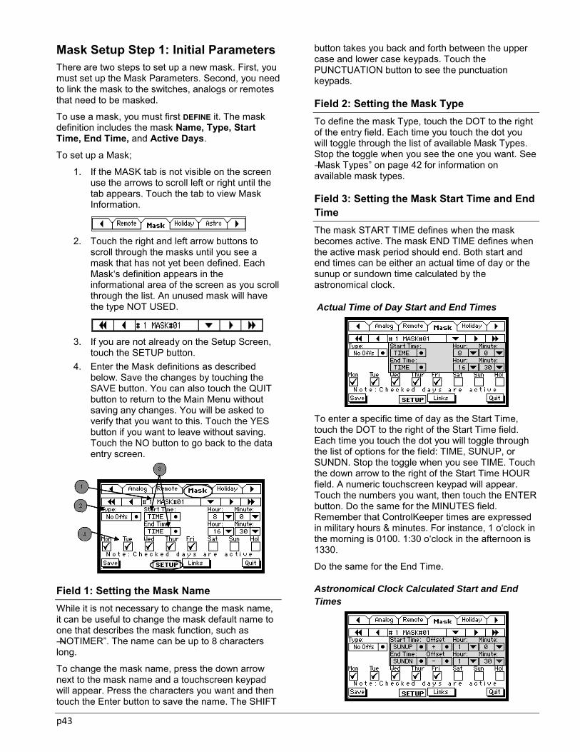
p43
Mask Setup Step 1: Initial Parameters There are two steps to set up a new mask. First, you must set up the Mask Parameters. Second, you need to link the mask to the switches, analogs or remotes that need to be masked.
To use a mask, you must first DEFINE it. The mask definition includes the mask Name, Type, Start Time, End Time, and Active Days.
To set up a Mask;
1. If the MASK tab is not visible on the screen use the arrows to scroll left or right until the tab appears. Touch the tab to view Mask Information.
2. Touch the right and left arrow buttons to scroll through the masks until you see a mask that has not yet been defined. Each Mask‘s definition appears in the informational area of the screen as you scroll through the list. An unused mask will have the type NOT USED.
3. If you are not already on the Setup Screen, touch the SETUP button.
4. Enter the Mask definitions as described below. Save the changes by touching the SAVE button. You can also touch the QUIT button to return to the Main Menu without saving any changes. You will be asked to verify that you want to this. Touch the YES button if you want to leave without saving. Touch the NO button to go back to the data entry screen.
Field 1: Setting the Mask Name While it is not necessary to change the mask name, it can be useful to change the mask default name to one that describes the mask function, such as ―NOTIMER‖. The name can be up to 8 characters long.
To change the mask name, press the down arrow next to the mask name and a touchscreen keypad will appear. Press the characters you want and then touch the Enter button to save the name. The SHIFT
button takes you back and forth between the upper case and lower case keypads. Touch the PUNCTUATION button to see the punctuation keypads.
Field 2: Setting the Mask Type To define the mask Type, touch the DOT to the right of the entry field. Each time you touch the dot you will toggle through the list of available Mask Types. Stop the toggle when you see the one you want. See ―Mask Types‖ on page 42 for information on available mask types.
Field 3: Setting the Mask Start Time and End Time The mask START TIME defines when the mask becomes active. The mask END TIME defines when the active mask period should end. Both start and end times can be either an actual time of day or the sunup or sundown time calculated by the astronomical clock.
Actual Time of Day Start and End Times
To enter a specific time of day as the Start Time, touch the DOT to the right of the Start Time field. Each time you touch the dot you will toggle through the list of options for the field: TIME, SUNUP, or SUNDN. Stop the toggle when you see TIME. Touch the down arrow to the right of the Start Time HOUR field. A numeric touchscreen keypad will appear. Touch the numbers you want, then touch the ENTER button. Do the same for the MINUTES field. Remember that ControlKeeper times are expressed in military hours & minutes. For instance, 1 o‘clock in the morning is 0100. 1:30 o‘clock in the afternoon is 1330.
Do the same for the End Time.
Astronomical Clock Calculated Start and End
Times

p44
NOTE: To enter SUNUP or SUNDN as the start or end time, you will need to have first configured your latitude and longitude into the controller. See ―Step 6: Setting the Astronomical Clock‖ on page 12 for latitude and longitude configuration steps.
Touch the DOT to the right of the Start Time field. Each time you touch the dot you will toggle through the list of options for the field: TIME, SUNUP, or SUNDN. Stop the toggle when you see the choice that you need.
Creating Offsets for the astronomical sunup and sundown times Note: The offset that you create in this field is specific to this mask, and is applied in addition to any offsets you may have entered when you defined the Astronomical Clock in the Panel Setup Screen.
You may want to have the mask be active a little before or after the calculated sundown or sunup times. To apply an offset to the calculated sunup or sundown time, touch the DOT to the right of the Offset Plus/Minus choice box. If you want to make the calculated time earlier, choose the Minus symbol (-). If you want to make the calculated time later, choose the Plus (+) symbol.
Touch the arrow to the right of the Offset Hours box. A touchscreen keypad will appear. Enter the hours you would like to add to or subtract from the calculated time, then touch the ENTER button. Do the same for the Offset Minutes.
Field 4: Setting the Mask Active Days A mask can be active on any combination of days of the week and can also be set to work on holidays. See ―Basic Programming Part 7: Setting up Holiday Dates‖ on page 38 for more information on setting holiday dates.
Touch the checkbox below each day of week that you want the mask to be active. A checkmark will appear, indicating that the mask being defined will be active on that day of week. If you do not want the mask to work on that day, touch the checkbox again to remove the checkmark. If the mask is to be active on defined holidays, remember to checkmark the HOL field.
Mask Setup Step 2: Linking Masks to Switch, Analog and Remote Inputs Each mask can be applied to some or all of the switch, analog or remote inputs in the ControlKeeper. You Link (or ―tie‖) a mask to the switches, analogs and remotes through the Mask Links Screen. Please note that only the switches, analogs and remotes that are setup as types other than not used will be shown in the links screen.
To link a mask to inputs:
1. If the MASK tab is not visible on the screen use the arrows to scroll left or right until the tab appears. Touch the tab to view Mask Information.
2. Touch the right and left arrow buttons to
scroll through the masks until you see the mask that you want to link to inputs. Each Mask‘s definition appears in the informational area of the screen as you scroll through the list.
3. Touch the LINKS button to get to the screen
for setting up which inputs this mask applies to.
4. Only switches, analogs and remotes that are
defined as types other than NOT USED appear on the list of available inputs. Touch the check box to the right of each input for which you want the mask to be active. The scrolling arrows will move the screen up and down to show additional inputs. To unlink an input, touch the checkbox to remove the checkmark.
5. When you have completed the Links touch
the SAVE button to save the changes. You can also touch the QUIT button to return to the MAIN SCREEN. If you leave the screen without saving the changes, you will be asked if that is what you want. Touch the NO button to remain on the screen, or touch the YES button to leave without saving any changes.
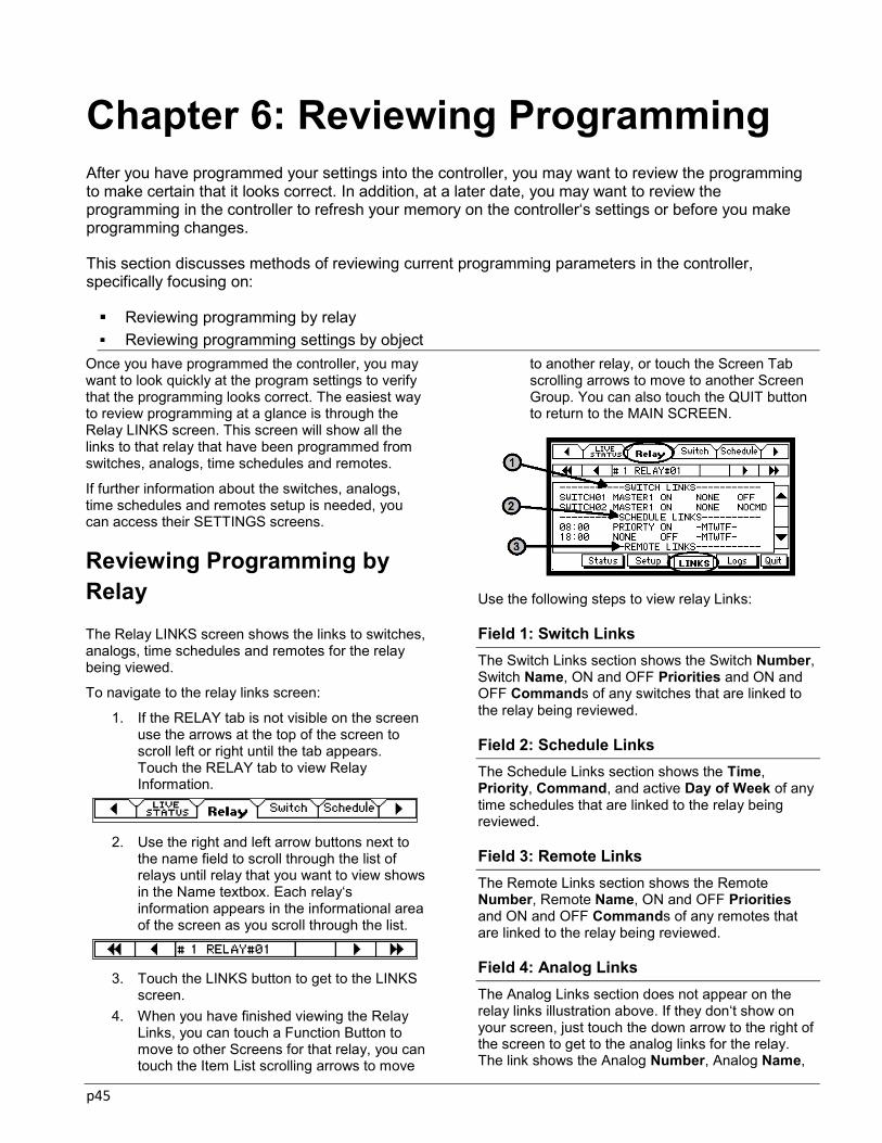
p45
Chapter 6: Reviewing Programming After you have programmed your settings into the controller, you may want to review the programming to make certain that it looks correct. In addition, at a later date, you may want to review the programming in the controller to refresh your memory on the controller‘s settings or before you make programming changes.
This section discusses methods of reviewing current programming parameters in the controller, specifically focusing on:
Reviewing programming by relay Reviewing programming settings by object
Once you have programmed the controller, you may want to look quickly at the program settings to verify that the programming looks correct. The easiest way to review programming at a glance is through the Relay LINKS screen. This screen will show all the links to that relay that have been programmed from switches, analogs, time schedules and remotes.
If further information about the switches, analogs, time schedules and remotes setup is needed, you can access their SETTINGS screens.
Reviewing Programming by Relay The Relay LINKS screen shows the links to switches, analogs, time schedules and remotes for the relay being viewed.
To navigate to the relay links screen:
1. If the RELAY tab is not visible on the screen use the arrows at the top of the screen to scroll left or right until the tab appears. Touch the RELAY tab to view Relay Information.
2. Use the right and left arrow buttons next to
the name field to scroll through the list of relays until relay that you want to view shows in the Name textbox. Each relay‘s information appears in the informational area of the screen as you scroll through the list.
3. Touch the LINKS button to get to the LINKS
screen. 4. When you have finished viewing the Relay
Links, you can touch a Function Button to move to other Screens for that relay, you can touch the Item List scrolling arrows to move
to another relay, or touch the Screen Tab scrolling arrows to move to another Screen Group. You can also touch the QUIT button to return to the MAIN SCREEN.
Use the following steps to view relay Links:
Field 1: Switch Links The Switch Links section shows the Switch Number, Switch Name, ON and OFF Priorities and ON and OFF Commands of any switches that are linked to the relay being reviewed.
Field 2: Schedule Links The Schedule Links section shows the Time, Priority, Command, and active Day of Week of any time schedules that are linked to the relay being reviewed.
Field 3: Remote Links The Remote Links section shows the Remote Number, Remote Name, ON and OFF Priorities and ON and OFF Commands of any remotes that are linked to the relay being reviewed.
Field 4: Analog Links The Analog Links section does not appear on the relay links illustration above. If they don‘t show on your screen, just touch the down arrow to the right of the screen to get to the analog links for the relay. The link shows the Analog Number, Analog Name,

p46
ON and OFF Priority, and ON and OFF Commands of any analogs that are linked to the relay being reviewed.
Reviewing Programming Settings At times, you may want to view all the settings for a switch, analog, time schedule or remote to get a complete picture of the settings that are currently programmed, beyond what the Relay LINKS screen shows. This can be done for each object by going into the SETUP screen for the object. In addition to the setup screen, it is possible to review settings for a switch, analog or remote through the STATUS screen of the object.
Switch Status Screen The Switch Input Status Screen has two pages: THE CURRENT STATUS of the input, and THE CURRENT SETTINGS of the input. The Switch Input Settings page shows how the switch has been programmed to work. You will not be able to make any changes to the Switch‘s programming on the Settings screen.
To View Switch Settings Screen:
1. If the SWITCH tab is not visible on the screen use the screen tab arrows at the top of the screen to scroll left or right until the tab appears. Touch the tab to view Switch Information.
2. Use the right and left arrow buttons by the
Switch Name field to scroll through the list of switches until you see the switch that you want to view. Each switch definition appears in the informational area of the screen as you scroll through the list.
3. In the Switch Status Screen, touch the
SETTINGS button on the right side of the screen.
4. When you have finished viewing the Switch
Settings, you can touch a Function Button to move to other Screens for that switch, you
can touch the Item List scrolling arrows to move to another switch, or touch the Screen Tab scrolling arrows to move to another Screen Group. You can also touch the QUIT button to return to the MAIN SCREEN.
Switch Input Settings Page The Switch Input Settings Page shows how the Switch Input has been programmed. You will not be able to make any changes to this programming while you are viewing the Settings Screen. You can toggle back and forth between STATUS and SETTINGS screens by touching the View button.
The Switch Settings fields show the switch settings for Type, Timer, Commands, Priorities, Channel the switch wires to (momentary, maintained or toggle type only), whether the switch is set up to Log or Broadcast, any Masks that have been linked, The switch Address (for Digita 1 and Digita 5 switches only), Feedback information (Digita or pilot lit switches only), and Lighted Switch settings (Pilot Lit switch only). For further information on these fields, please refer to ―Basic Programming Part 3: Setting Up Contact Closure Switches‖ on page 18.
Analog Status Screen The Analog Input Status Screen has two pages: THE CURRENT STATUS of the input, and THE CURRENT SETTINGS of the input. The Analog Input Settings page shows how the analog has been programmed to work. You will not be able to make any changes to the Analog‘s programming on the Settings screen.
To View Analog Settings Screen:
1. If the ANALOG tab is not visible on the screen use the screen tab arrows at the top of the screen to scroll left or right until the tab appears. Touch the tab to view Analog Information.
2. Use the right and left arrow buttons by the
Analog Name field to scroll through the list of analogs until you see the analog that you want to view. Each analog definition appears

p47
in the informational area of the screen as you scroll through the list.
3. If you are not already in the Settings Screen,
touch the VIEW button on the right side of the screen.
4. When you have finished viewing the Analog
Settings, you can touch a Function Button to move to other Screens for that analog, you can touch the Item List scrolling arrows to move to another analog, or touch the Screen Tab scrolling arrows to move to another Screen Group. You can also touch the QUIT button to return to the MAIN SCREEN.
Analog Input Settings Page The Analog Input Settings Page shows how the Analog Input has been programmed. You will not be able to make any changes to this programming while you are viewing the Settings Screen. You can toggle back and forth between STATUS and SETTINGS screens by touching the View Button.
The Analog Settings fields show the settings for Type, Timer, Commands, Priorities, Endpoints, Thresholds, Channel the analog wires to, whether the analog is set up to Log or Broadcast, and any Masks that have been linked, and Minimum ON or OFF Times that may have been programmed for the input. For further information on these fields, please see ―Basic Programming Part 5: Setting up Analogs‖ on page 30.

p48
Chapter 7: Changing or Deleting Programming This chapter briefly talks about changing and deleting programming in the ControlKeeper T.
Changing Programming Deleting Time Schedules and Holiday Dates
The ControlKeeper T allows you to easily change the panel programming. In addition to changing programming, both the Time Schedule Tab and Holiday Tab allow you to delete a schedule or holiday date by touching a delete button visible on the page.
Changing Programming through the Setup Screens You may want to change the way programming has been defined for a relay, switch, analog, remote, time schedule, mask or holiday. To change these items:
1. If the desired object tab is not visible on the screen use the arrows to scroll left or right until the tab appears. Touch the tab to view the item‘s information.
2. Use the right and left arrow buttons to scroll through the object list until the name of the item that you want to change appears in the Name textbox.
3. When you see the item you want, touch the SETUP button to get the set up screen for the chosen item.
4. Make the changes you want, referring to the information about setting up programming in earlier chapters of this manual.
5. Touch the SAVE button to store the changes. You can also touch the QUIT button to return to the MAIN SCREEN. If you leave the screen without saving the changes, you will be asked if that is what you want to do. Touch the NO button to remain on the screen, or touch the YES button to leave without saving any changes.
Note on Making Items Inactive You may want to have your programming for a certain item stop functioning for a period of time. One way of doing this is to make the item Inactive by changing its type to NOT USED. As long as the object is set up as NOT USED, its parameters will not function. This can be done for relays, switches,
analogs, remotes, and masks. As long as an item is set up as a NOT USED type, regardless of items linked to it, the item will not function.
Note on Unlinking Items Time Schedules, Switches, Analogs and Remotes are linked to Relays in the links screens. If you no longer want a relay to respond to a certain time schedule or react to a switch, analog or remote, remove the link to the relay by accessing the Time Schedule, Switch, Analog or Remote LINK page and removing the checkmark for the relay. Relays that are still linked to these objects will continue to operate as normal.
Masks can also be linked to either the analog, remote or switches that they apply to. To remove a mask from an analog, remote or switch, access the Mask LINK page and remove the checkmark for the remote or switch you do not want it to be applied to.
Deleting Time Schedules and Holiday Dates It is possible to delete entirely a time schedule or holiday date. Other items will need to be made NOT USED or unlinked from the control objects to prevent their programming from occurring.
Deleting Time Schedules You may want to delete a schedule completely, rather than changing its programming. Deleting the schedule will delete all links to the schedule as well as revert the schedule settings back to the default NOT USED schedule parameters.
To delete a schedule:
1. If the SCHEDULE tab is not visible on the screen use the arrows to scroll left or right until the tab appears. Touch the tab to view Schedule Information.

p49
2. Use the right and left arrow buttons to scroll through the schedules until you see the time schedule that you want to delete. There may be several Time Schedules for the same time of day, so be sure you have stopped at the schedule you want to delete.
3. Touch the SETUP button to be sure you are on
the Setup page.
4. Touch the DELETE button to delete the
schedule. A message will pop up asking you to confirm the deletion of the schedule. Touch YES to continue and delete. Touch NO to revert back to the schedule without deleting it.
5. When you have finished, touch the SAVE button
to save the change. You can also touch the QUIT button to return to the MAIN SCREEN. If you leave the screen without saving the changes, you will be asked if that is what you want. Touch the NO button to remain on the screen, or touch the YES button to leave without saving any changes.
Deleting Holiday Dates If you are setting up holiday dates that will not occur on a yearly basis, it may be necessary to delete them after they have occurred to prevent unwanted lighting schedule interruption in the future.
To delete a Holiday Date:
1. If the HOLIDAY tab is not visible on the screen use the arrows to scroll left or right until the tab appears. Touch the tab to view the HOLIDAY Screen.
2. Use the right and left arrow buttons to scroll
through the list of Holidays. Stop scrolling when you see the Holiday Date you want to delete.
3. Touch the DELETE button. A message will pop up asking if you are sure you wish to delete the entry. Touch YES to continue and delete. Touch NO to revert back to the holiday without deleting it.
4. The screen will show dashes ―—― in the date fields and the name field will be blank when the holiday date has been deleted.
5. Touch the SAVE button to save the change. You can touch any Screen Tab Scrolling Arrow to move through the Screen Tabs or the Item List Scrolling Arrows to move through the list of Holidays, or touch the QUIT button to return to the MAIN SCREEN.

p50
Chapter 8: Viewing Live Status The Live Status Screens available in the ControlKeeper T include the main relay status screens, an expanded relay status screen, a live switch status screen, a live analog status screen and a live remote status screen. The use of these screens and information they contain will be discussed in this chapter.
Live Relay Status Switch Status Analog Status Remote Status.
The Live Status Screens available in the ControlKeeper T allow you to view the real-time status of your relays, switches, analogs and remotes. These screens can be invaluable when troubleshooting your lighting control programming.
Live Relay Status There are three screen areas in the ControlKeeper T that can be used to view live relay status. These include the Main Status Screen, the Relay Status Screen, and the Expanded Relay Status Screen. All of these can be used to tell the state of the relay. In addition, some of these screens show further information about the command in effect and other items about the command that can be useful to look at, especially when troubleshooting.
Main Status Screen The Main Status Screen shows the current status of all the relays in the ControlKeeper T. This screen is visible when the enclosure door is shut.
The default screen in the CKT is the main status screen. To access this screen if you have been in other touchscreens, navigate to the Live Status tab and then use the QUIT button. It will bring you to the Main Status Screen.
Relay Status The status of all 48 relays, as set by programming or manual commands, is shown within this screen. Any
relays that are ON will be shaded and have the word ON at the bottom of the relay box. Any relays that are OFF will be clear of shading and will display the word OFF at the bottom of the relay box. As commands occur to the relays, the relay boxes in this screen will update with the live status.
Touch the screen in any location to move to the Live Relay Status Screen, where you can see the time, date and cause of the current status for the relays.
Relays that do not physically exist in the enclosure will be ―grayed-out‖. For example if there are only 32 relays in the enclosure the Main Status Screen will look as shown below.
All relays will appear ―grayed-out‖ if there is a problem with panel communications.
Hardware Override Status The Main Status Screen also indicates when all the relays have been overridden ON or OFF by the three position rocker switch on the Relay Stack Controller Card (RSC) located at the bottom of the cabinet. This override switch takes precedence over the programmed status of the relays.
See ―Panel Override Using the RSC Switch‖ on page 59 of the manual.

p51
Relay Stack Controller Overrides All Relays OFF
Relay Stack Controller Overrides All Relays ON
Live Relay Status The Live Status Tab shows the relays in a list view. This view shows the status of each relay, along with the current command that is in effect for the relay, the cause of that command, and the time and date that the command was issued. If the relay was commanded by a switch, analog or remote, the cause will be the NAME of the switch, analog or remote. The command will show the word SCHEDULE if it was caused by a time schedule, the words RELAY SW if the hardware switch on the relay was used, the word KEYBOARD if the relay was turned on or off from the ControlKeeper T touchscreen, or the word NETWORK if optional computer software was used to issue the on or off command
To access the live status tab from the main status screen, touch anywhere on the screen. You will be brought automatically to this screen.
If you are not on the main status screen, use the tab arrows at the top of the screen to navigate to the Live Status Tab.
Expanded Relay Status Screen In addition to the main status and live relay status screens, the expanded status is especially useful when troubleshooting. This screen not only tells you the current relay state but gives further information about the command that is in effect.
To access the expanded relay status screen:
1. If the RELAY tab is not visible on the screen use the arrows to scroll left or right until the tab appears. Touch the RELAY tab to view Relay Information.
2. Use the right and left arrow buttons to scroll
through the list of relays until you see the relay that you want to view. Each relay definition appears in the informational area of the screen as you scroll through the list.
3. Touch the STATUS button to get to the Relay
Expanded Status Screen.
4. When you have finished viewing the Relay
Status Screen, you can touch a Function Button to move to other Screens for that relay, you can touch the Item List scrolling arrows to move to another relay, or touch the Screen Tab scrolling arrows to move to another Screen Group. You can also touch the QUIT button to return to the MAIN SCREEN.
State Field This field reports the ON or OFF state of the relay as well as the priority of the command in effect.
Time Field The time and date that the command in effect was issued.
Cause Field This field reports the cause of the command in effect. This field may display a switch, analog or remote name that issued the command, the word

p52
SCHEDULE if it was caused by a time schedule, the words RELAY SW if the individual relay override switch was used on the relay itself, the word KEYBOARD if the relay was turned on or off from the ControlKeeper T touchscreen, or the word NETWORK if optional computer software was used to issue the on or off command.
Timer Count Field If the command had a timer, this field shows how much time is left before the timer expires.
Schedule State/Schedule Time If there are schedules assigned, these fields will show the command that should be in effect by schedule and the time and date the schedule occurred. Note: This may not be the command that is currently in effect.
Next State/ Next Cause/ Next Time Fields If there are schedules assigned, the controller will indicate the next ON or OFF command that is scheduled in the controller as well as the time and date that this schedule will occur.
Runtime Hours This field will show an accumulation of time that the relay has been ON since the last time the relay run time was cleared. This can be helpful for relamping.
Live Switch Status The Switch Input Status Screen has two pages: THE CURRENT STATUS of the input, and THE CURRENT SETTINGS of the input. The VIEW button toggles between the two pages. This section deals specifically with the status section of these screens. For information on the settings page, please see ―Switch Status Screen‖ on page 46.
The Switch Input Status page reports information about the last command issued by the input.
To view Switch Status:
1. If the SWITCH tab is not visible on the screen use the screen tab arrows to scroll left or right until the tab appears. Touch the tab to view Switch Information.
2. Use the right and left arrow buttons to scroll
through the list of switches until you see the switch that you want to view. Each switch definition appears in the informational area of the screen as you scroll through the list.
3. Touch the STATUS button at the bottom of the screen.
4. When you have finished viewing the Switch
Status, you can touch the View Button to move to the Settings Screen, a Function Button to move to other Screens for that switch, you can touch the Item List scrolling arrows to move to another switch, or touch the Screen Tab scrolling arrows to move to another Screen Group. You can also touch the QUIT button to return to the MAIN SCREEN.
State Field The last ON/OFF command issued by this Switch, followed by the time and date of that command.
Timer Count Field If the switch has been programmed with a Timed On command, and the timer is counting, the Timer Count field shows how many minutes are left before the Switch Input command times out and automatically turns off the associated lighting loads. If the switch has no active timer, the time shows 0 minutes.
Active Mask Field If there is a Mask that is currently active and affecting the way the switch works, the Mask Type will show in this field. If there is no mask active, the field will display ―Not Used‖. One type mask can prevent the switch from turning lights ON or OFF during a certain period of time. Another type mask allows you to specify that a switch input timer cannot issue an OFF command while a time schedule is running. There are several other Mask Types available. In order to use a Mask, you must first define the Mask through the Mask Setup Screen and then link it to the inputs that it affects on the Mask Links Screen. See ―Using Masks in the ControlKeeper System on page 42 for further information.
View Button Toggle back and forth between STATUS and SETTINGS screens by touching the View button.

p53
Live Analog Status The Analog Input Status Screen has two pages: the CURRENT STATUS of the input and the CURRENT SETTINGS of the input. The VIEW button toggles between the two pages. This section deals specifically with the status section of these screens.
The Analog Input Status Screen reports information about the last command issued by the Analog.
To view Analog Status:
1. If the ANALOG tab is not visible on the screen use the arrows to scroll left or right until the Analog tab appears. Touch the tab to view Analog Information.
2. Use the right and left arrow buttons to scroll
through the analogs until you see the input that you want to view. Each analog input‘s definition appears in the informational area of the screen as you scroll through the list.
3. If the status screen is not already showing,
touch the STATUS button to view the Analog Status information.
4. When you have finished viewing the Analog
Status, you can touch the VIEW Button to move to the Analog Settings Screen, a Function Button to move to other Screens for that analog, the Item List scrolling arrows to move to another analog, or touch the Screen Tab scrolling arrows to move to another Screen Group. You can also touch the QUIT button to return to the MAIN SCREEN.
State Field The last ON/OFF command issued by this Analog, followed by the time and date of that command.
Timer Count Field If the Analog has been programmed with a Timed On command, and the timer is counting, the Timer Count
field shows how many minutes are left before the Analog Input command times out and automatically turns off the associated lighting loads. If the Analog has no active timer, the Timer Count shows 0 minutes..
Active Mask If the Analog has been programmed with a Mask this field shows if any of those masks are active and affecting the way the Analog works. If there is no active mask, the screen shows ―Not Used‖. One type of mask can prevent the Analog from turning lights ON or OFF during a certain period of time. Another type of mask can allow you to specify that an Analog input timer cannot issue an OFF command while a time schedule is running. In order to use a Mask, you must first define the Mask time and type through the Mask Setup Screen. Masks are linked to the inputs that it to affect in the Mask Link screen. See ―Using Masks in the ControlKeeper System‖ on page 42
Reading The current reading from the sensor.
View Button Toggle back and forth between STATUS and SETTINGS screens by touching the View button.
Live Remote Status
The Remote Input Status Screen has two pages: the CURRENT STATUS of the input, and the CURRENT SETTINGS of the input. The VIEW button toggles between the two pages. This section deals specifically with the status section of these screens.
The Remote Input Status page reports information about the last command issued by the Remote.
To view Remote Status:
1. If the REMOTE tab is not visible on the screen use the arrows to scroll left or right until the Remote tab appears. Touch the tab to view Remote Information.
2. Use the right and left arrow buttons to scroll
through the remotes until you see the input that you want to view. Each remote input‘s definition appears in the informational area of the screen as you scroll through the list.
3. If the status screen is not already showing,
touch the STATUS button to view the Remote Status information.
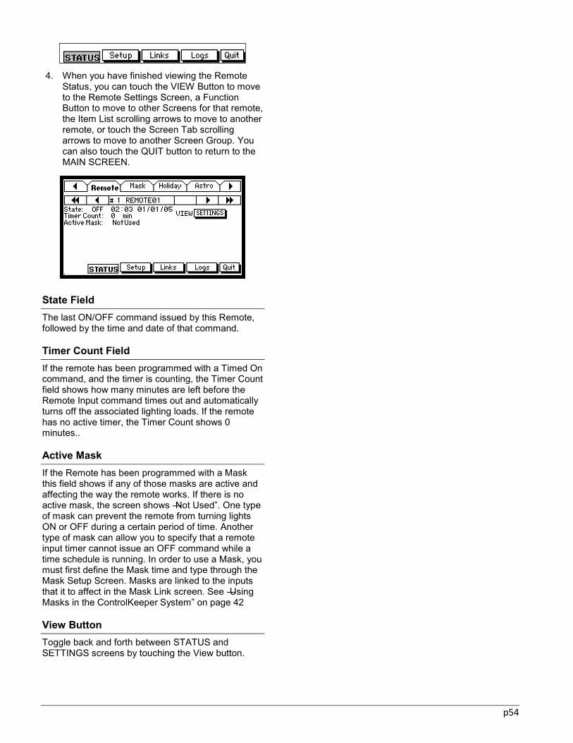
p54
4. When you have finished viewing the Remote
Status, you can touch the VIEW Button to move to the Remote Settings Screen, a Function Button to move to other Screens for that remote, the Item List scrolling arrows to move to another remote, or touch the Screen Tab scrolling arrows to move to another Screen Group. You can also touch the QUIT button to return to the MAIN SCREEN.
State Field The last ON/OFF command issued by this Remote, followed by the time and date of that command.
Timer Count Field If the remote has been programmed with a Timed On command, and the timer is counting, the Timer Count field shows how many minutes are left before the Remote Input command times out and automatically turns off the associated lighting loads. If the remote has no active timer, the Timer Count shows 0 minutes..
Active Mask If the Remote has been programmed with a Mask this field shows if any of those masks are active and affecting the way the remote works. If there is no active mask, the screen shows ―Not Used‖. One type of mask can prevent the remote from turning lights ON or OFF during a certain period of time. Another type of mask can allow you to specify that a remote input timer cannot issue an OFF command while a time schedule is running. In order to use a Mask, you must first define the Mask time and type through the Mask Setup Screen. Masks are linked to the inputs that it to affect in the Mask Link screen. See ―Using Masks in the ControlKeeper System‖ on page 42
View Button Toggle back and forth between STATUS and SETTINGS screens by touching the View button.
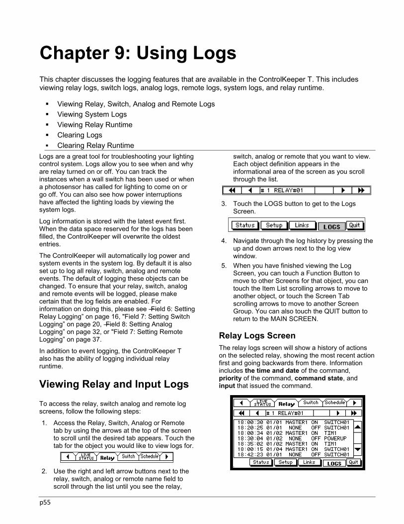
p55
Chapter 9: Using Logs This chapter discusses the logging features that are available in the ControlKeeper T. This includes viewing relay logs, switch logs, analog logs, remote logs, system logs, and relay runtime.
Viewing Relay, Switch, Analog and Remote Logs Viewing System Logs Viewing Relay Runtime Clearing Logs Clearing Relay Runtime
Logs are a great tool for troubleshooting your lighting control system. Logs allow you to see when and why are relay turned on or off. You can track the instances when a wall switch has been used or when a photosensor has called for lighting to come on or go off. You can also see how power interruptions have affected the lighting loads by viewing the system logs.
Log information is stored with the latest event first. When the data space reserved for the logs has been filled, the ControlKeeper will overwrite the oldest entries.
The ControlKeeper will automatically log power and system events in the system log. By default it is also set up to log all relay, switch, analog and remote events. The default of logging these objects can be changed. To ensure that your relay, switch, analog and remote events will be logged, please make certain that the log fields are enabled. For information on doing this, please see ―Field 6: Setting Relay Logging‖ on page 16, "Field 7: Setting Switch Logging‖ on page 20, ―Field 8: Setting Analog Logging‖ on page 32, or "Field 7: Setting Remote Logging‖ on page 37.
In addition to event logging, the ControlKeeper T also has the ability of logging individual relay runtime.
Viewing Relay and Input Logs To access the relay, switch analog and remote log screens, follow the following steps:
1. Access the Relay, Switch, Analog or Remote tab by using the arrows at the top of the screen to scroll until the desired tab appears. Touch the tab for the object you would like to view logs for.
2. Use the right and left arrow buttons next to the
relay, switch, analog or remote name field to scroll through the list until you see the relay,
switch, analog or remote that you want to view. Each object definition appears in the informational area of the screen as you scroll through the list.
3. Touch the LOGS button to get to the Logs
Screen.
4. Navigate through the log history by pressing the
up and down arrows next to the log view window.
5. When you have finished viewing the Log Screen, you can touch a Function Button to move to other Screens for that object, you can touch the Item List scrolling arrows to move to another object, or touch the Screen Tab scrolling arrows to move to another Screen Group. You can also touch the QUIT button to return to the MAIN SCREEN.
Relay Logs Screen The relay logs screen will show a history of actions on the selected relay, showing the most recent action first and going backwards from there. Information includes the time and date of the command, priority of the command, command state, and input that issued the command.
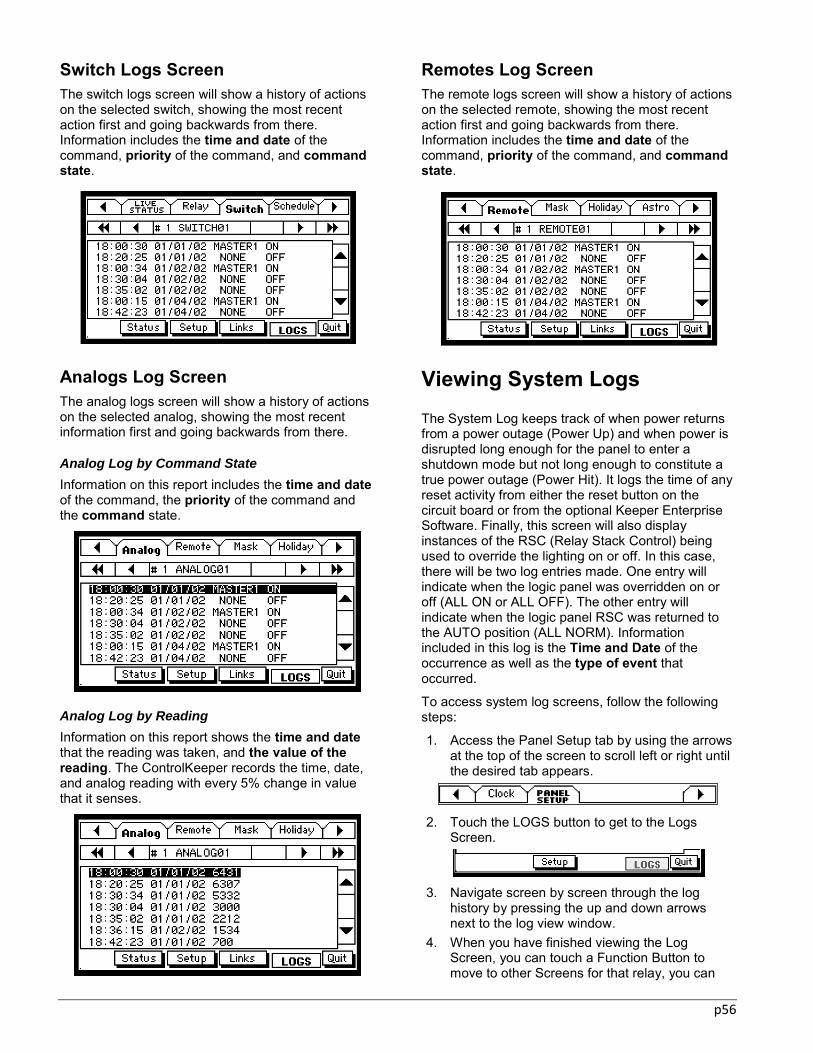
p56
Switch Logs Screen The switch logs screen will show a history of actions on the selected switch, showing the most recent action first and going backwards from there. Information includes the time and date of the command, priority of the command, and command state.
Analogs Log Screen The analog logs screen will show a history of actions on the selected analog, showing the most recent information first and going backwards from there.
Analog Log by Command State
Information on this report includes the time and date of the command, the priority of the command and the command state.
Analog Log by Reading
Information on this report shows the time and date that the reading was taken, and the value of the reading. The ControlKeeper records the time, date, and analog reading with every 5% change in value that it senses.
Remotes Log Screen The remote logs screen will show a history of actions on the selected remote, showing the most recent action first and going backwards from there. Information includes the time and date of the command, priority of the command, and command state.
Viewing System Logs
The System Log keeps track of when power returns from a power outage (Power Up) and when power is disrupted long enough for the panel to enter a shutdown mode but not long enough to constitute a true power outage (Power Hit). It logs the time of any reset activity from either the reset button on the circuit board or from the optional Keeper Enterprise Software. Finally, this screen will also display instances of the RSC (Relay Stack Control) being used to override the lighting on or off. In this case, there will be two log entries made. One entry will indicate when the logic panel was overridden on or off (ALL ON or ALL OFF). The other entry will indicate when the logic panel RSC was returned to the AUTO position (ALL NORM). Information included in this log is the Time and Date of the occurrence as well as the type of event that occurred.
To access system log screens, follow the following steps:
1. Access the Panel Setup tab by using the arrows at the top of the screen to scroll left or right until the desired tab appears.
2. Touch the LOGS button to get to the Logs
Screen.
3. Navigate screen by screen through the log
history by pressing the up and down arrows next to the log view window.
4. When you have finished viewing the Log Screen, you can touch a Function Button to move to other Screens for that relay, you can
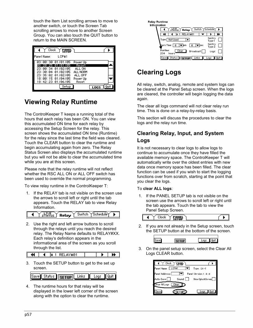
p57
touch the Item List scrolling arrows to move to another switch, or touch the Screen Tab scrolling arrows to move to another Screen Group. You can also touch the QUIT button to return to the MAIN SCREEN.
Viewing Relay Runtime The ControlKeeper T keeps a running total of the hours that each relay has been ON. You can view this accumulated ON time for each relay by accessing the Setup Screen for the relay. This screen shows the accumulated ON time (Runtime) for the relay since the last time the field was cleared. Touch the CLEAR button to clear the runtime and begin accumulating again from zero. The Relay Status Screen also displays the accumulated runtime but you will not be able to clear the accumulated time while you are at this screen.
Please note that the relay runtime will not reflect whether the RSC ALL ON or ALL OFF switch has been used to override the normal programming.
To view relay runtime in the ControlKeeper T:
1. If the RELAY tab is not visible on the screen use the arrows to scroll left or right until the tab appears. Touch the RELAY tab to view Relay Information.
2. Use the right and left arrow buttons to scroll
through the relays until you reach the desired relay. The Relay Name defaults to RELAY#XX. Each relay‘s definition appears in the informational area of the screen as you scroll through the list.
3. Touch the SETUP button to get to the set up
screen.
4. The runtime hours for that relay will be
displayed in the lower left corner of the screen along with the option to clear the runtime.
Clearing Logs All relay, switch, analog, remote and system logs can be cleared at the Panel Setup screen. When the logs are cleared, the controller will begin logging the data again.
The clear all logs command will not clear relay run time. This is done on a relay-by-relay basis.
This section will discuss the procedures to clear the logs and the relay run time.
Clearing Relay, Input, and System Logs It is not necessary to clear logs to allow logs to continue to accumulate once they have filled the available memory space. The ControlKeeper T will automatically write over the oldest entries with new data once memory space has been filled. The clear function can be used if you wish to start the logging functions over from scratch, starting at the point that you clear the logs.
To clear ALL logs:
1. If the PANEL SETUP tab is not visible on the screen use the arrows to scroll left or right until the tab appears. Touch the tab to view the Panel Setup Screen.
2. If you are not already in the Setup screen, touch
the SETUP button at the bottom of the screen.
3. On the panel setup screen, select the Clear All
Logs CLEAR button.
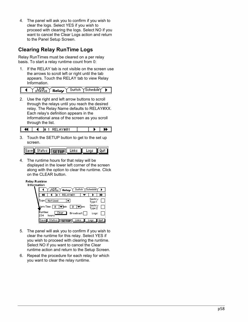
p58
4. The panel will ask you to confirm if you wish to clear the logs. Select YES if you wish to proceed with clearing the logs. Select NO if you want to cancel the Clear Logs action and return to the Panel Setup Screen.
Clearing Relay RunTime Logs Relay RunTimes must be cleared on a per relay basis. To start a relay runtime count from 0:
1. If the RELAY tab is not visible on the screen use the arrows to scroll left or right until the tab appears. Touch the RELAY tab to view Relay Information.
2. Use the right and left arrow buttons to scroll
through the relays until you reach the desired relay. The Relay Name defaults to RELAY#XX. Each relay‘s definition appears in the informational area of the screen as you scroll through the list.
3. Touch the SETUP button to get to the set up
screen.
4. The runtime hours for that relay will be
displayed in the lower left corner of the screen along with the option to clear the runtime. Click on the CLEAR button.
5. The panel will ask you to confirm if you wish to
clear the runtime for this relay. Select YES if you wish to proceed with clearing the runtime. Select NO if you want to cancel the Clear runtime action and return to the Setup Screen.
6. Repeat the procedure for each relay for which you want to clear the relay runtime.

p59
Chapter 10: Manually Turning Relays On and Off This chapter discusses the override features that are available in the ControlKeeper T.
Individual Relay Manual Override Switch Enclosure Manual Override Switch Touchscreen Relay Override
At some point, you may wish to turn on or off relays from the ControlKeeper T panel without using a time schedule, switch, analog or remote command.
The ControlKeeper T allows you to override relays on or off by using either Hardware Overrides or Touchscreen Overrides. These methods are discussed in detail below.
Hardware Relay Overrides
Hardware Relay Overrides can be done at the panel level or at the relay level. At the panel level, each enclosure has an all relay override switch on the RSC (relay stack controller). At the relay level, each relay has a relay override switch to allow for individual relay control.
Panel Override Using the RSC Switch All ControlKeeper T enclosures contain an override card at the bottom of the cabinet called a Relay Stack Controller (RSC). This card is in charge of passing control signals from the logic panel up through the relay stack. It also has a manual three-position ALL OFF/ AUTO/ ALL ON switch that allows for relay overrides.
The RSC override switch can be used to turn on or off lighting regardless of whether the CKT control panel is installed in the enclosure.
Enclosure with Relay Stack Controller (RSC)
If this switch is used to the ALL ON or right position, all relays in the controller will close, regardless of programmed state or relay type. If this switch is used
to the ALL OFF or left position, all the relays in the enclosure will open, regardless of programmed state or relay type. If the switch is in the AUTO position, the controller will run scheduled programming or respond to individual relay hardware override commands.
The RSC is a MASTER hardware override for the enclosure. If the switch is in the ALL ON or ALL OFF position, no further commands from the ControlKeeper T or hardware relay override switches will be obeyed until the RSC has been placed in the AUTO position.
If the RSC has been used to turn on or off lighting loads, the relay status screens will not reflect this. However, on the main screen, the words OVERRIDE ON or OVERRIDE OFF will flash, indicating that the panel has been overridden. This allows notification of the override and also allows users to see what state the relay will return to when the RSC Switch is moved back to the Auto position. The panel will also log the instance of the RSC override being used in the System log.
RSC Override Indicators
Please note, if the RSC ON or OFF command has been used, relay run times may not reflect accurate run time figures.
Relay Override Using the Individual Relay Switches Each Relay in the ControlKeeper T has a hardware override switch that will allow for temporary override of the lighting load. This switch is in the high voltage section of the controller. If you are not an electrician, or rated for work in a high voltage environment, it is

p60
not recommended that you access these switches from a safety concern.
The relay override switch is in a slightly different location based on the type of relays that your enclosure contains. At the time of this manual‘s release, there are three different available relay types. This includes the Serial Standard Relay Module (sSRM), Serial Two Pole Relay Module (sTPRM), and the Serial Latching Relay Module (sLRM). The location of the override card switch for these three different modules is indicated in the diagrams below.
Relay Override Switch Placement
To override a relay, press the small reset button next to the relay until the relay is in the correct ON or OFF state. The LED next to the reset button will be lit when the relay is closed.
The manual override of the relay will stay in effect until the next command is received from the ControlKeeper T, RSC override switch, or another relay override. For this reason it is a temporary override only.
The manual relay override switches can be used to turn on or off lighting regardless of whether the CKT is installed in the enclosure. However, if the RSC has been used to override the lighting ALL ON or ALL OFF, the manual relay override switches will not be operable until the RSC is placed in the AUTO position.
If the manual relay override switch has been used to override the relay, the relay status screen will be updated to show that the relay is on or off by a cause type of RELAY SW.
Touchscreen Relay Overrides
The ControlKeeper T panel allows you to turn on and off relays from the Touchscreen of the controller. The status of the relay in the relay status page will show a cause of KEYBOARD if a relay has been overridden in this method.
A Touchscreen Relay Override is a temporary override. It will stay in effect until the next command is received from the ControlKeeper T or until the RSC override switch or individual relay switch override is used.
To perform a manual override of a relay from the CKT:
1. Access the Live Status tab by using the arrows at the top of the screen to scroll left or right until the desired tab appears. Touch the Live Status tab to access the screen.
2. In the Live Status Screen, use the scroll arrows
on the right side of the screen to highlight the relay you wish to override.
3. Use the ON or OFF buttons at the bottom of the
screen to issue the relay command.
4. Repeat as needed for additional relays. 5. When you have finished turning on or off relays,
you can touch the Screen Tab scrolling arrows to move to another Screen Group. You can also touch the QUIT button to return to the MAIN SCREEN.

p61
Chapter 11: User Information This section contains information specific to the maintenance of your lighting control system as well as installation of the lighting control enclosure and logic board.
ControlKeeper T Maintenance ControlKeeper T Memory Information
ControlKeeper T Maintenance
Very little maintenance is necessary to upkeep your ControlKeeper T lighting control system after it has been set up.
Recommended Maintenance includes:
Relay loads should be tightened down on a scheduled basis to prevent loosening of high voltage wires.
Low voltage wiring should be inspected at the panel to verify that wires have not come loose from terminated points.
The LCD Display should be wiped clean of dust with a soft cloth. DO NOT use any type of cleanser.
Holiday dates should be programmed into the controller on a yearly basis.
ControlKeeper T Memory Information
The ControlKeeper T stores its programming in flash memory. This negates the need to have power to the board in order to maintain the record of its programming. Regardless of time that power to the panel is down, the ControlKeeper T should power up with its programming intact.
The ControlKeeper T has an on board capacitor (no maintenance required) for maintenance of parameters which are not stored in flash memory. This includes the clock time, log information, and last known state of the relays. This capacitor will store these parameters for approximately 7 days without power.
If a controller is powered down for more than 7 days, the memory of programming will be intact when the controller is powered up, however, the clock time and date may be incorrect on power up and the relays may not assume the proper state. Logs also may be lost. To restore the ControlKeeper T to normal operation, set the clock time and date. This should allow the ControlKeeper T to re-evaluate schedule activity and assume the properly programmed state.
Technical Support
If you can‘t find the answers to your questions in this manual, contact Cooper Controls Technical Support at (800)553-3879. Standard support includes answering questions regarding your hardware and software and over the phone assistance with programming and troubleshooting of your Greengate system.
When you call, you should be near your control panel and be prepared to give the following information:
The panel type: (in this case the CKT) The panel version: The version information is
included in the information displayed in the Panel Setup screen.
The exact wording of any messages that may have appeared on your display.
A description of what happened and what you were doing when the problem occurred.
A description of how you tried to solve the problem.
If a particular area is experiencing a problem, the relay number that the area‘s lighting circuit is wired to.

p62
Item Reference Diagrams
Low Voltage Section Reference
1. System Status LEDs (Network, Power, Status) 2. CKT Reset Button 3. Power Connection to Logic Board 4. Communications Connection to Logic Board 5. Digital Switch Port Status LEDs 6. Digital Switch Gateway Connection Point 7. Serial Communications Port 8. Lighting Network Port 1 (CAT5 RJ45
Connection) 9. Lighting Network Port 2 (CAT5 RJ45
Connection) 10. Lighting Network Termination Block (Twisted
Pair Connection). 11. Network Termination Jumper 12. LCD Display Contrast Tuning Potentiometer 13. Local/Remote Jumpers 14. Remote Power Connector (DC Gnd, +24V) 15. Contact Input Switch Wiring Channels 16. Relay Stack Controller Power Wiring from
Transformer 17. RSC Status LED 18. Communication Cable Connection to RSC from
CKT 19. CKT Power Connection from RSC 20. RSC Power LED 21. RSC ALL OFF/AUTO/ALL ON Switch with
Indicator LEDs 22. Analog Input Wiring Channels
High Voltage Section Reference
23. Relay Cards in the High Voltage Section 24. Center Rail for Relay Stack 25. Individual Relay Override Switch 26. Relay Status Indicator 27. Relay Card Status LED 28. Connection from Center Rail into RSC

p63
Appendix A: This section contains supplemental information specific to legacy support of the previous digital switch architecture. For installation using a version 5.7.0 or higher ControlKeeper- T logic board for connection to Digita model switches, please refer to this section for programming information.
Setting Digita Switch Parameters
In addition to dry contact closure switches, the ControlKeeper T supports the use of Digita switches. The Greengate lighting controller‘s onboard 24VDC power supply can support the following # of Digita Switch Stations:
Panel Type # of Stations *
ControlKeeper T 48 size 22
ControlKeeper T 32 size 28
ControlKeeper T 16 size 28
*This figure is contingent on no other devices being powered from the panel‘s 24VDC power supply. If photosensors, motion sensors, or other pilot lit switches are being used, this may reduce the available power for the Digita Switch network. Please consult technical support to determine the total number of devices that may be powered in a mixed device environment.
Digita switch stations are available in the following configurations:
Digita 1 Digita 5 – 1 Button Digita 5 – 2 Button Digita 5 – 3 Button Digita 5 – 4 Button Digita 5 – 5 Button
The Digita 1 Switch is a decorator style rocker switch which has no status feedback. The Digita 5 switch has from one to five control buttons, each with an LED indicator that can be programmed to provide either relay status feedback or switch status feedback. With the Digita 5 switch model, each button of the Digita 5 switch must be set up as a separate Switch Input.
There 64 available Switch Inputs in the CKT that may be assigned to any Digita Switch button or other switch devices in the lighting controller. Each Digita Switch has a rotary address switch that allows for
addressing the station so that the ControlKeeper T can recognize which switch has been actuated and thus control the programmed relays.
Digita 1 and Digita 5 Switch Address Dials
Please see the Digita Switch Installation Instructions for more information about installing and configuring Digita Switches.
Configuring the Switch Bus Type The ControlKeeper T version 5.7.0 and higher can support the current GDS architecture and also contains legacy support for the previous Digita switch model series. Before you can begin programming your Digita switch stations, you will need to ensure that the Switch Bus type is set for ‗DIGITA‘ operation.
1. If the PANEL SETUP tab is not visible on the screen use the arrows to scroll left or right until the tab appears. Touch the tab to view the Panel Setup Screen.
2. If you are not already in the Setup screen, touch
the SETUP button at the bottom of the screen.
3. Make certain that the Switch Bus type field is
set for DIGITA and press the SAVE button.
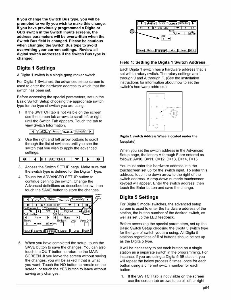
p64
If you change the Switch Bus type, you will be prompted to verify you wish to make this change. If you have previously programmed a Digita or GDS switch in the Switch Inputs screens, the address parameters will be overwritten when the Switch Bus field is changed. Please be cautious when changing the Switch Bus type to avoid overwriting your current settings. Review all digital switch addresses if the Switch Bus type is changed.
Digita 1 Settings A Digita 1 switch is a single gang rocker switch.
For Digita 1 Switches, the advanced setup screen is used to enter the hardware address to which that the switch has been set.
Before accessing the special parameters, set up the Basic Switch Setup choosing the appropriate switch type for the type of switch you are using.
1. If the SWITCH tab is not visible on the screen use the screen tab arrows to scroll left or right until the Switch Tab appears. Touch the tab to view Switch Information.
2. Use the right and left arrow buttons to scroll
through the list of switches until you see the switch that you wish to apply the advanced settings.
3. Access the Switch SETUP page. Make sure that
the switch type is defined for the Digita 1 type. 4. Touch the ADVANCED SETUP button to
continue defining the switch. Change the Advanced definitions as described below, then touch the SAVE button to store the changes.
5. When you have completed the setup, touch the
SAVE button to save the changes. You can also touch the QUIT button to return to the MAIN SCREEN. If you leave the screen without saving the changes, you will be asked if that is what you want. Touch the NO button to remain on the screen, or touch the YES button to leave without saving any changes.
Field 1: Setting the Digita 1 Switch Address Each Digita 1 switch has a hardware address that is set with a rotary switch. The rotary settings are 1 through 9 and A through F. (See the installation instructions for information about how to set the switch‘s hardware address.)
Digita 1 Switch Address Wheel (located under the
faceplate)
When you set the switch address in the Advanced Setup page, the letters A through F are entered as follows: A=10, B=11, C=12, D=13, E=14, F=15
You must enter this hardware address into the touchscreen set up for the switch input. To enter this address, touch the down arrow to the right of the switch address. A drop-down numeric touchscreen keypad will appear. Enter the switch address, then touch the Enter button and save the change.
Digita 5 Settings For Digita 5 model switches, the advanced setup screen is used to enter the hardware address of the station, the button number of the desired switch, as well as set up the LED feedback.
Before accessing the special parameters, set up the Basic Switch Setup choosing the Digita 5 switch type for the type of switch you are using. All Digita 5 stations regardless of # of buttons should be set up as the Digita 5 type.
It will be necessary to set each button on a single station as a separate switch in the programming. For instance, if you are using a Digita 5-5B station, you will repeat the below process 5 times, once for each button using a different switch number for each button.
1. If the SWITCH tab is not visible on the screen use the screen tab arrows to scroll left or right
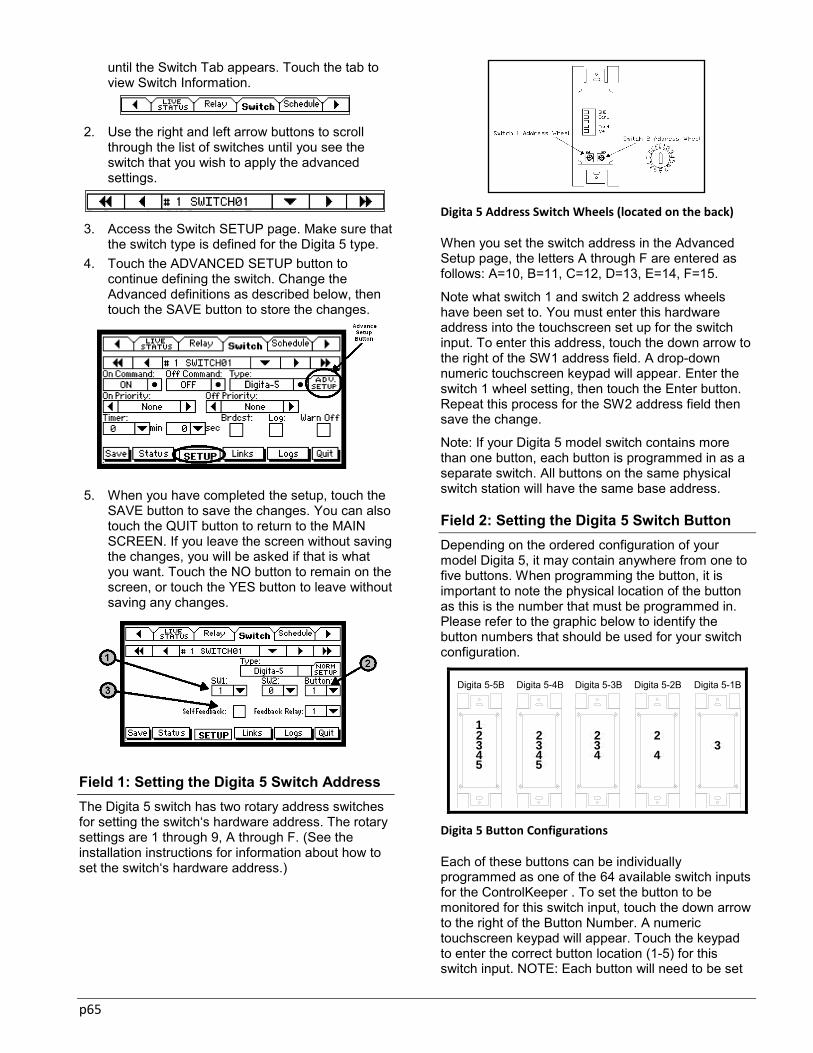
p65
until the Switch Tab appears. Touch the tab to view Switch Information.
2. Use the right and left arrow buttons to scroll
through the list of switches until you see the switch that you wish to apply the advanced settings.
3. Access the Switch SETUP page. Make sure that
the switch type is defined for the Digita 5 type. 4. Touch the ADVANCED SETUP button to
continue defining the switch. Change the Advanced definitions as described below, then touch the SAVE button to store the changes.
5. When you have completed the setup, touch the
SAVE button to save the changes. You can also touch the QUIT button to return to the MAIN SCREEN. If you leave the screen without saving the changes, you will be asked if that is what you want. Touch the NO button to remain on the screen, or touch the YES button to leave without saving any changes.
Field 1: Setting the Digita 5 Switch Address The Digita 5 switch has two rotary address switches for setting the switch‘s hardware address. The rotary settings are 1 through 9, A through F. (See the installation instructions for information about how to set the switch‘s hardware address.)
Digita 5 Address Switch Wheels (located on the back)
When you set the switch address in the Advanced Setup page, the letters A through F are entered as follows: A=10, B=11, C=12, D=13, E=14, F=15.
Note what switch 1 and switch 2 address wheels have been set to. You must enter this hardware address into the touchscreen set up for the switch input. To enter this address, touch the down arrow to the right of the SW1 address field. A drop-down numeric touchscreen keypad will appear. Enter the switch 1 wheel setting, then touch the Enter button. Repeat this process for the SW2 address field then save the change.
Note: If your Digita 5 model switch contains more than one button, each button is programmed in as a separate switch. All buttons on the same physical switch station will have the same base address.
Field 2: Setting the Digita 5 Switch Button Depending on the ordered configuration of your model Digita 5, it may contain anywhere from one to five buttons. When programming the button, it is important to note the physical location of the button as this is the number that must be programmed in. Please refer to the graphic below to identify the button numbers that should be used for your switch configuration.
3234 4
22345
Digita 5-1BDigita 5-3B Digita 5-2BDigita 5-4B
5432
Digita 5-5B
1
Digita 5 Button Configurations
Each of these buttons can be individually programmed as one of the 64 available switch inputs for the ControlKeeper . To set the button to be monitored for this switch input, touch the down arrow to the right of the Button Number. A numeric touchscreen keypad will appear. Touch the keypad to enter the correct button location (1-5) for this switch input. NOTE: Each button will need to be set

p66
up as a separate switch in the ControlKeeper T programming.
Field 3: Setting Digita 5 Switch Feedback Each Digita 5 Button has an LED that will light up. You can choose from two sources for the status feedback for this switch input: Self Feedback and Feedback from a Relay. Some sort of feedback must be set up for each Digita 5 button that is programmed. Failure to set up a proper feedback will result in the switch not being operational.
Self Feedback
When you choose Self Feedback, the indicator light will track with the last command issued from the switch. The LED will be lit if the switch has issued an ON command and it will be OFF when the switch has issued an OFF command. (This method does not take into account that some other input such as another switch or a time schedule may have turned ON or OFF lights. For instance, if the switch is turned ON, the LED will light. If a time schedule turns off the relays that the switch runs, the LED in the switch will continue to be ON until that switch issues an OFF command.)
To choose this option, touch the Self Feedback check box and a checkmark will appear, activating the Self Feedback Lighted Switch Option. (The Feedback Relay data field will then show ―- -―.) Touch the check box again to de-activate this feature.
Feedback Relay
Alternatively, you can choose to have the button indicator show the status of one of the relays controlled by the button. When you choose this option, the indicator light will be ON when the relay is on and OFF when the relay is off. With this method, if another switch or time schedule turns the feedback relay off or on, the switch will reflect the proper status.
Touch the down arrow to the right of the Feedback Relay data field. A drop-down numeric touchscreen keypad will appear. Touch the keypad numbers to enter the relay number that you want for feedback status, then touch the enter button. When you choose Relay Feedback, the Self Feedback option will automatically be deactivated.
When you are programming through the touchscreen, a feedback relay must be assigned from within the same panel that the digita switch network is wired. With the optional Keeper Enterprise Software, it is possible to have the feedback relay be programmed in another panel. Please contact technical support for further details.

p67
Appendix B: This section contains information gathering forms for the ControlKeeper T. Please use these for documenting your programmed settings before, during and after programming. These forms include:
Relay worksheet Contact closure switch worksheet GDS station worksheet Analog worksheet Time schedule worksheet

p68
Relay Schedule Worksheet

p69
Contact Closure Switch Input Worksheet

p70
Greengate Digital Switch Worksheet

p71
Analog Input Worksheet
Time Schedule Worksheet

Document# 9850-000238-00
North American Headquarters203 Cooper CirclePeachtree City, GA 30269
P: 800-553-3879F: 800-954-7016
International HeadquartersUsk House, Lakeside,Llantarnam Park,Cwmbran, NP44 3HD. UK
P: +44 (0) 1923 495495F: +44 (0) 1633 867880
Cooper US, Inc.600 Travis, Suite 5600Houston, Texas 77002P: 713-209-8400www.cooperindustries.com
Cooper Controls, Greengate, Novitas, Yes Box, PCI Lighting Control Systems, VisionTouch, VisionSwitch, MicroSet, Digita, ControlKeeper, LiteKeeper, AnalogKeeper, IntelliRelay, DemandKeeper, NeoSwitch,Revio, and Ineo are valuable trademarks of Cooper Industries in the U.S. and other countries. You are not permitted to use Cooper Trademarks without the prior written consent of Cooper Industries.


![Georgia Power. Electrical Service & Metering Installations.blueBook[1]](https://img.pdfslide.us/doc/110x75/5447d1b4b1af9f4f618b45e8/georgia-power-electrical-service-metering-installationsbluebook1.jpg)