Embed Size (px)
Citation preview
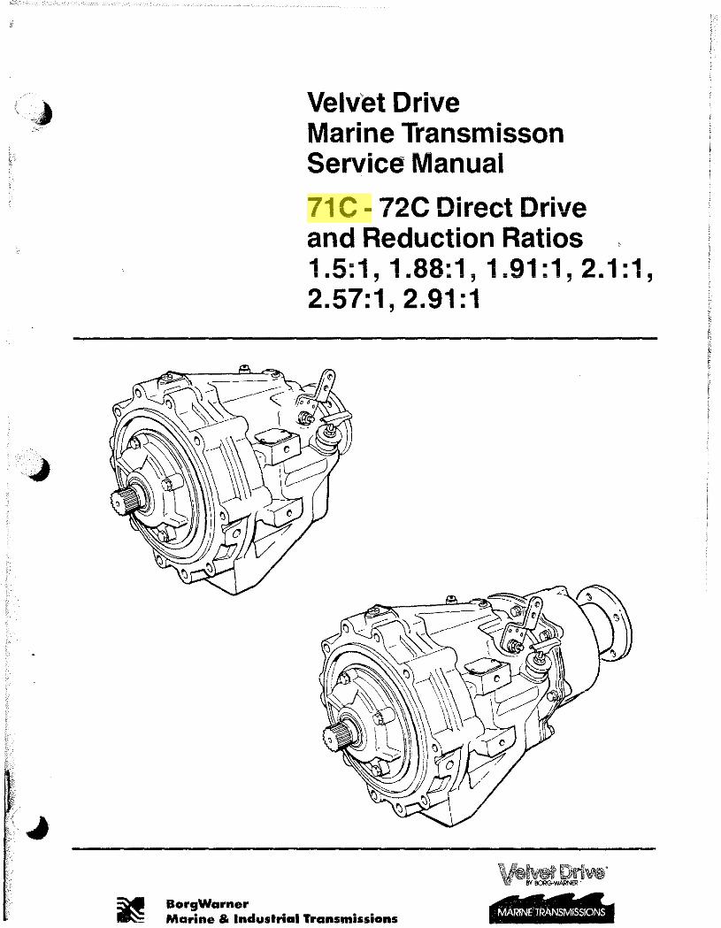
Velvet Drive Marine Transmisson Service Manual
71 C - 72C Direct Drive and Reduction Ratios 1 .5: 1, 1.88: 1, 1.91: 1 , 2. 1 : 1 , 2.57:1, 2.91:1
~ BorgVfarner ~ Marine & Industrial Transmissions MARINE TRANSMISSlONS

( ..
•. ",
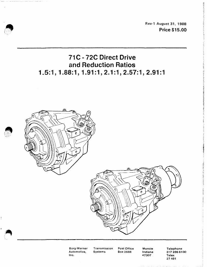
71 C - 72C Direct Drive
Rev-1 August 31,1988
Price $15.00
and Reduction Ratios 1.5:1,1.88:1,1.91:1,2.1:1,2.57:1,2.91:1
Borg·Warner Transmission Post Office Automotive, Systems Box 2688 Inc.
Muncie Indiana 47307
Telephone 317 2866100 Telex 27491

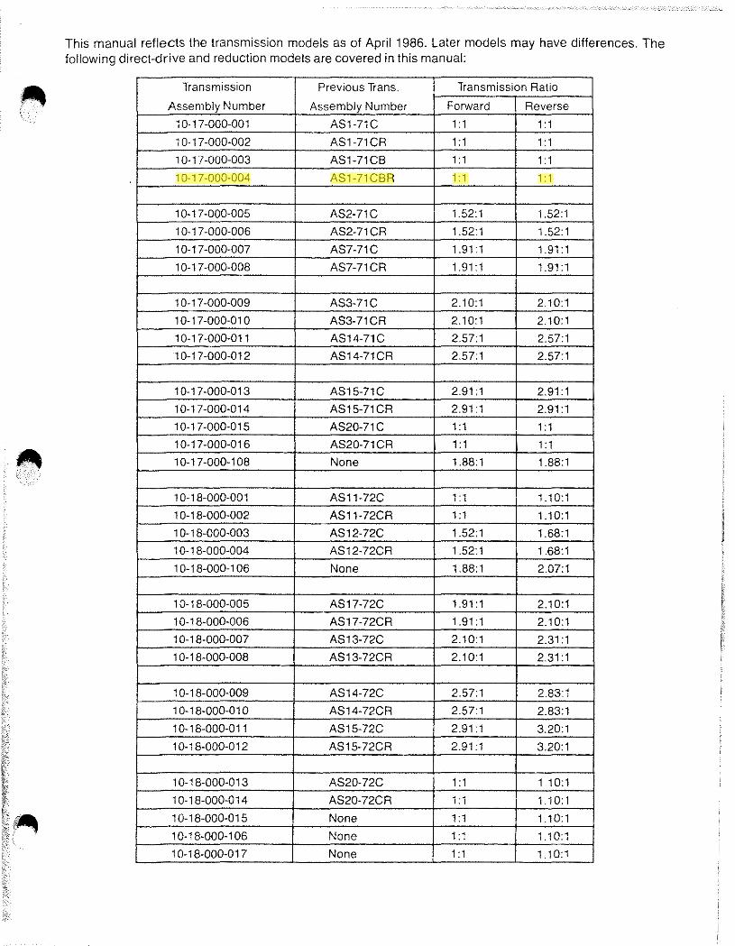
This manual reflects the transmission models as of April 1986. Later models may have differences. The following direct-drive and reduction models are covered in this manual:
Transmission Previous Trans. Transmission Ratio
Assembly Number Assembly Number Forward Reverse
1 0-17-000-001 ASl-71C 1 : 1 1 : 1
10-17-000-002 ASl-71CR 1: 1 1 : 1
1 0-1 7-000-003 ASl-71CB 1 : 1 1 : 1
1 0-17-000-004 ASl-71CBR 1 : 1 1 : 1
10-17-000-005 AS2-71C 1.52:1 1.52:1
1 0-1 7-000-006 AS2-71CR 1.52:1 1.52:1
10-17-000-007 AS7-71C 1.91: 1 1.91: 1
1 0-1 7-000-008 AS7-71CR 1.91: 1 1.91 :1
1 0-1 7-000-009 AS3-71C 2.10:1 2.10:1
10-17-000-010 AS3-71CR 2.10:1 2.10:1
10-17-000-011 AS14-71C 2.57:1 2.57:1
10-17-000-012 AS14-71CR 2.57:1 2.57:1
10-17-000-013 AS15-71C 2.91 :1 2.91 :1
10-17-000-014 AS15-71CR 2.91 :1 2.91 :1
10-17-000-015 AS20-71 C 1: 1 1: 1
10-17-000-016 AS20-71CR 1 : 1 1: 1
10-17-000-108 None 1.88:1 1.88:1
1 0-1 8-000-001 AS11-72C 1 : 1 1.10:1
10-18-000-002 AS11-72CR 1: 1 1.10:1
1 0-18-000-003 AS12-72C 1.52:1 1.68:1
1 0-1 8-000-004 AS12-72CR 1.52:1 1.68:1
1 0-18-000-1 06 None 1.88:1 2.07:1
1 0-1 8-000-005 AS17-72C 1.91 :1 2.10:1
1 0-18-000-006 AS17-72CR 1.91 :1 2.10:1
10-18-000-007 AS13-72C 2.10:1 2.31 :1
1 0-1 8-000-008 AS13-72CR 2.10:1 2.31 :1
1 0-1 8-000-009 AS14-72C 2.57:1 2.83:1
1 0-18-000-01 0 AS14-72CR 2.57:1 2.83:1
1 0-18-000-011 AS15-72C 2.91 :1 3.20:1
10-18-000-012 AS15-72CR 2.91 :1 3.20:1
10-18-000-013 AS20-72C 1 : 1 1.10:1
1 0-18-000-014 AS20-72CR 1: 1 1.10:1
10-18-000-015 None 1 : 1 1.10:1
1 0-18-000-1 06 None 1 : 1 1.10:1
1 0-18-000-017 None 1 : 1 1.10:1
The following international symbols are used in this service manual. • WARNING: THIS SYMBOL WARNS OF POSSIBLE PERSONAL INJURY.
CAUTION: This symbol warns of possible damage to transmission.
OEM: Original Equipment Manufacturer (Boat/Engine Manufacturer).
•
•
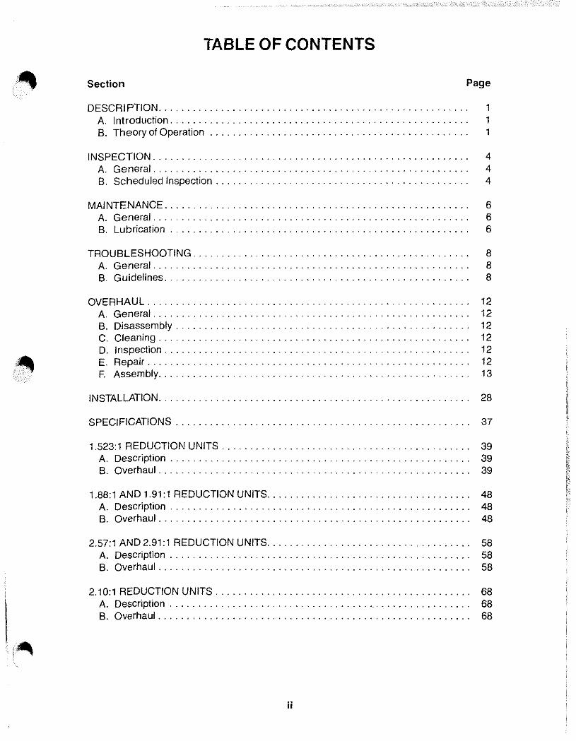
TABLE OF CONTENTS
Section Page
DESCRIPTION. . . . . . . . . . . . . . . . . . . . . . . . . . . . . . . . . . . . . . . . . . . . . . . . . . . . . . . 1 A. Introduction..................................................... 1 B. Theory of Operation ............................................. .
INSPECTION. . . . . . . . . . . . . . . . . . . . . . . . . . . . . . . . . . . . . . . . . . . . . . . . . . . . . . . . 4 A. General........................................................ 4 B. Scheduled Inspection. . . . . . . . . . . . . . . . . . . . . . . . . . . . . . . . . . . . . . . . . . . . . 4
MAINTENANCE. . . . . . . . . . . . . . . . . . . . . . . . . . . . . . . . . . . . . . . . . . . . . . . . . . . . . . 6 A. General.... . . . . . . . . . . . . . . . . . . . . . . . . . . . . . . . . . . . . . . . . . . . . . . . . . . . . 6 B. Lubrication . . . . . . . . . . . . . . . . . . . . . . . . . . . . . . . . . . . . . . . . . . . . . . . . . . . . . 6
TROUBLESHOOTING. . . . . . . . . . . . . . . . . . . . . . . . . . . . . . . . . . . . . . . . . . . . . . . . . 8 A. General........................................................ 8 B. Guidelines. . . . . . . . . . . . . . . . . . . . . . . . . . . . . . . . . . . . . . . . . . . . . . . . . . . . . . 8
OVERHAUL ........................................................ , 12 A. General ...... .................. - . . . . . . . . . . . . . . . . . . . . . . . . . . . . . .. 12 B. Disassembly.................................................... 12 C. Cleaning... . . . . . . . . . . . . . . . . . . . . . . . . . . . . . . . . . . . . . . . . . . . . . . . . . . .. 12 D. Inspection...................................................... 12 E. Repair......................................................... 12 F. Assembly....................................................... 13
INSTALLATION. . . . . . . . . . . . . . . . . . . . . . . . . . . . . . . . . . . . . . . . . . . . . . . . . . . . . .. 28
SPECIFICATIONS . . . . . . . . . . . . . . . . . . . . . . . . . . . . . . . . . . . . . . . . . . . . . . . . . . .. 37
1.523:1 REDUCTION UNITS ........................................... , 39 A. Description . . . . . . . . . . . . . . . . . . . . . . . . . . . . . . . . . . . . . . . . . . . . . . . . . . . .. 39 B. Overhaul. . . . . . . . . . . . . . . . . . . . . . . . . . . . . . . . . . . . . . . . . . . . . . . . . . . . . .. 39
1.88:1 AND 1.91:1 REDUCTION UNITS. . . . . . . . . . . . . . . . . . . . . . . . . . . . . . . . . . .. 48 A. Description..................................................... 48 B. Overhaul....................................................... 48
2.57:1 AND 2.91:1 REDUCTION UNITS. . . . . . . . . . . . . . . . . . . . . . . . . . . . . . . . . . .. 58 A. Description . . . . . . . . . . . . . . . . . . . . . . . . . . . . . . . . . . . . . . . . . . . . . . . . . . . .. 58 B. Overhaul ...................................................... , 58
2.10:1 REDUCTION UNITS ............................................. 68 A. Description ................................... , . . . . . . . . . . . . . . . .. 68 B. Overhaul. . . . . . . . . . . . . . . . . . . . . . . . . . . . . . . . . . . . . . . . . . . . . . . . . . . . . .. 68
. {AI\
ii
LIST OF FIGURES
Title Page
1. 71 C and 72C Transmission Assembly. . . . . . . . . . . . . . . . . . . . . . . . . . . . . . . . . . 1 2. Typical Installation. . . . . . . . . . . . . . . . . . . . . . . . . . . . . . . . . . . . . . . . . . . . . . . . . 2 3. Forward Power Flow. . . . . . . . . . . . . . . . . . . . . . . . . . . . . . . . . . . . . . . . . . . . . . . 2 4. Reverse Power Flow. . . . . . . . . . . . . . . . . . . . . . . . . . . . . . . . . . . . . . . . . . . . . . . 2 5. Hydraulic Circuit Schematic . . . . . . . . . . . . . . . . . . . . . . . . . . . . . . . . . . . . . . . . . 3 6. Bushing Installation .............................................. " 13 7A. Shift Cable Adjustment. . . . . . . . . . . . . . . . . . . . . . . . . . . . . . . . . . . . . . . . . . .. 28 7B. Oil to Cooler Outlet. . . . . . . . . . . . . . . . . . . . . . . . . . . . . . . . . . . . . . . . . . . . . .. 28 8. 71 C and 72C Transmission Assembly - Current Production. . . . . . . . . . . . . . . . .. 29 9. Optional Drive Gear Alarm Kits ..................................... " 35
10. 1.523: 1 Reduction Units - Current Production .......................... " 45 11. 1.523:1 Reduction Units - Early Production ............................ " 47 12. 1.88:1 and 1.91:1 Reduction Units - Current Production .................. " 54 13. 1.88:1 and 1.91:1 Reduction Units - Early Production. . . . . . . . . . . . . . . . . . . . .. 57 14. 2.57:1 and 2.91:1 Reduction Units - Current Production .................. " 64 15. 2.57:1 and 2.91:1 Reduction Units - Early Production. . . . . . . . . . . . . . . . . . . . .. 67 16. 2.10:1 Reduction Units - Current Production. . . . . . . . . . . . . . . . . . . . . . . . . . . .. 74 17. 2.10:1 Reduction Units-Early Production ............................ 77
LIST OF TABLES
Title Page
1. Technical Specifications . . . . . . . . . . . . . . . . . . . . . . . . . . . . . . . . . . . . . . . . . . . . . 1 2. Scheduled Inspections . . . . . . . . . . . . . . . . . . . . . . . . . . . . . . . . . . . . . . . . . . . . . . 4 3. Troubleshooting. . . . . . . . . . . . . . . . . . . . . . . . . . . . . . . . . . . . . . . . . . . . . . . . . . . . 9 4. Bolt and Fastener Torques (Non-Lubricated) ............................ " 37 5. Spring Dimensions. . . . . . . . . . . . . . . . . . . . . . . . . . . . . . . . . . . . . . . . . . . . . . . .. 37 6. Test Pressures ................................................... " 38
iii
•
•
•
• ' •
DESCRIPTION
SHIFT LEVER COOLER OUTLET
(SEE FIG. 7B, PAGE 28)
DIPSTICK
BREATHER
COOLER RETURN ---"-"" ..... ~~~
NOTE: SHOWN WITHOUT REDUCTION UNIT
Figure 1. 71 C and 72C Transmission Assembly
12646A
A. INTRODUCTION (See Figure 1).
The 71 C and 72C transmissions consist of a planetary gear set and multiple disc clutches. The input and output shafts are in line.
valve are forward-neutral-reverse. An internal regulator valve controls system pressure. Oil discharged by the regulator valve is sent to the oil cooler.
B. THEORY OF OPERATION. Hydraulic Pressure is provided by a crescent type pump. The pump is driven at engine speed by the input shaft. Oil from the pump is sent to the control valve. The positions on the control
General. Forward is direct drive. A planetary gear set (1.1 to 1.0 ratio for 72C, and 1.0 to 1.0 ratio for 71 C) is used to obtain reverse.
Table 1. Technical Specifications
DESCRIPTION MODEL 71C MODEL 72C
Speeds One Forward One Forward One Reverse One Reverse
Horsepower Gasoline (maximum) 310 HP @ 4200 RPM 475 HP @ 4200 RPM Diesel (maximum) 182 HP @ 3200 RPM 274 HP @ 3200 RPM
Torque and Input Speed See Ratings Charts See Ratings Charts (Form No. 1237) (Form No. 1237)
Approximate Dry Weight Direct Drive 95 lb. 109 lb. Reduction 145 lb. 153 lb.
1
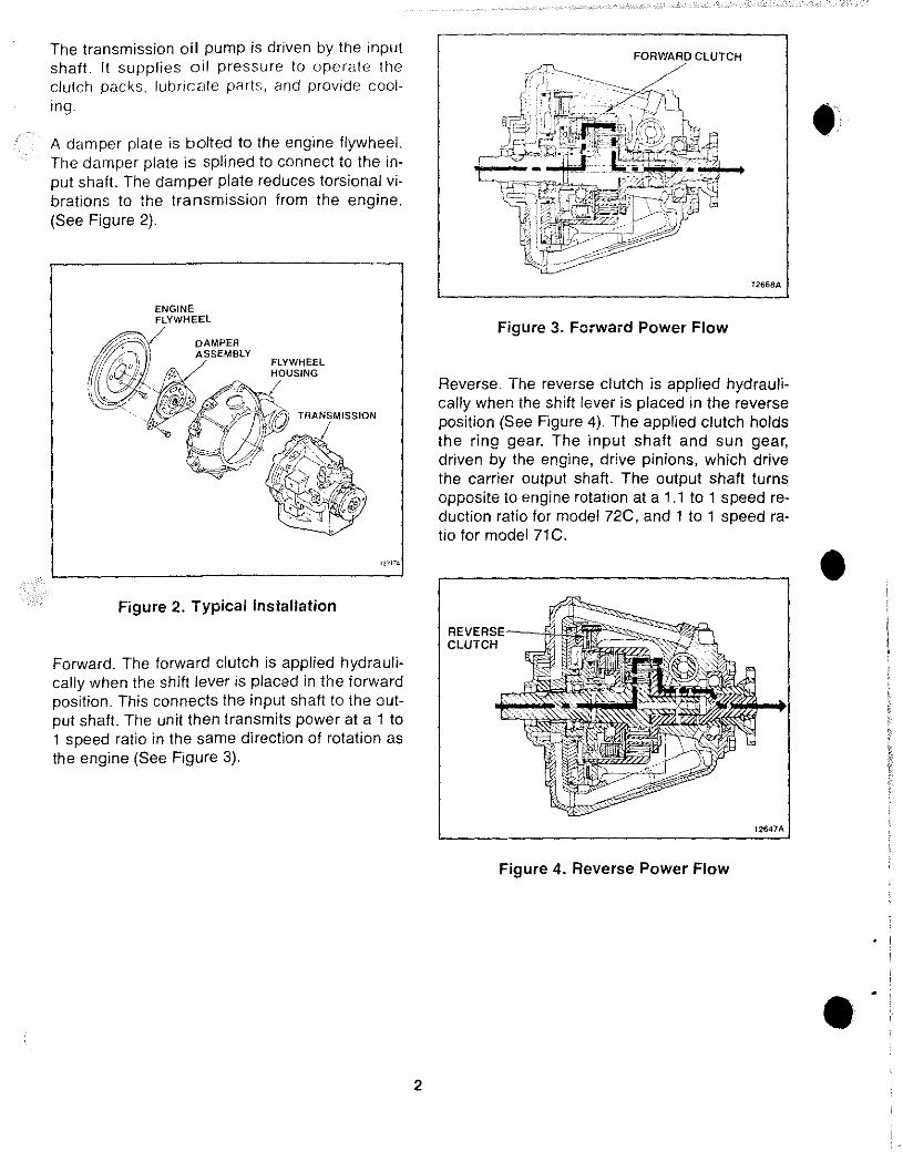
The transmission oi I pump is driven by the input shaft. It supplies oil pressure to operate the clutch packs, lubricate parts, and provide cooling.
A damper plate is bolted to the engine flywheel. The damper plate is splined to connect to the input shaft, The damper plate reduces torsional vibrations to the transmission from the engine, (See Figure 2),
FLYWHEEL HOUSING
Figure 2. Typical Installation
Forward. The forward clutch is applied hydraulically when the shift lever is placed in the forward position. This connects the input shaft to the output shaft. The unit then transmits power at a 1 to 1 speed ratio in the same direction of rotation as the engine (See Figure 3),
2
12668A
Figure 3. Forward Power Flow
Reverse. The reverse clutch is applied hydraulically when the shift lever is placed in the reverse position (See Figure 4). The applied clutch holds the ring gear. The input shaft and sun gear, driven by the engine, drive pinions, which drive the carrier output shaft. The output shaft turns opposite to engine rotation at a 1,1 to 1 speed reduction ratio for model 72C, and 1 to 1 speed ratio for model 71C.
REVERSE--!~iir;~~':j~~ CLUTCH ~
12647A
Figure 4. Reverse Power Flow
•
•
•
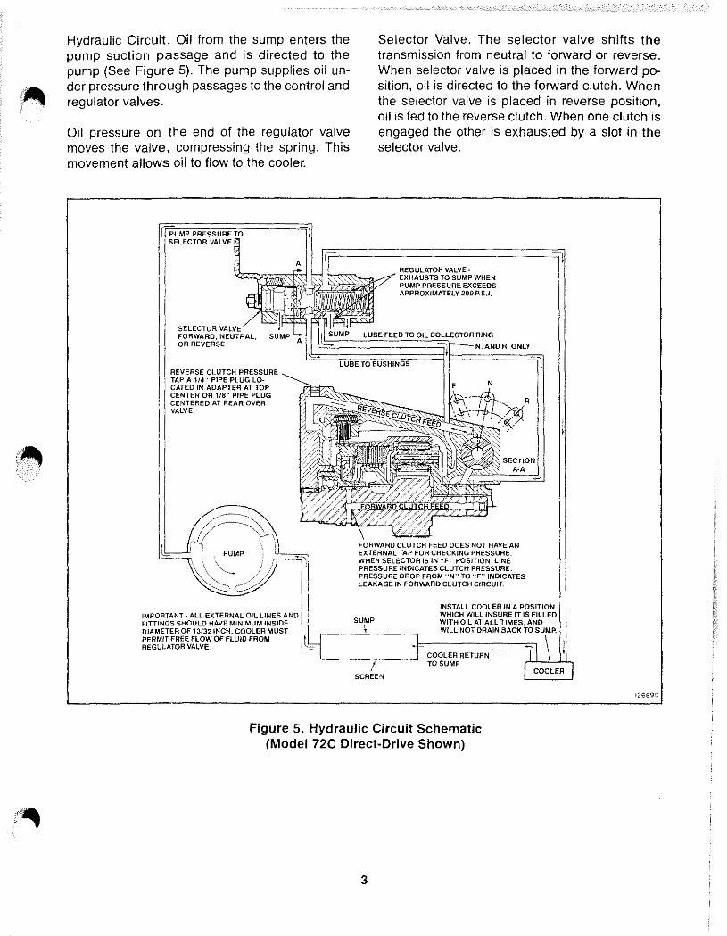
Hydraulic Circuit. Oil from the sump enters the pump suction passage and is directed to the pump (See Figure 5). The pump supplies oil under pressure through passages to the control and regulator valves.
Oil pressure on the end of the regulator valve moves the valve, compressing the spring. This movement allows oil to flow to the cooler.
A
Selector Valve. The selector valve shifts the transmission from neutral to forward or reverse. When selector valve is placed in the forward position, oil is directed to the forward clutch. When the selector valve is placed in reverse pOSition, oil is fed to the reverse clutch. When one clutch is engaged the other is exhausted by a slot in the selector valve.
REGULATOR VAlVE-'(ZZ:JI~i~~ ~0":w~,~?' EXHAUSTS TO SUMP WHEN
PUMP PRESSURE EXCEEDS APPROXIMATELY 200 P.S.I.
SELECTOR FORWARD, NEU'TR'.L. OR REVERSE
REVERSE CLUTCH PRESSURE TAP A 114 n PIPE PLUG lOCATED IN ADAPTER AT TOP CENTER OR 1/8~ PIPE PLUG CENTERED AT REAR OVER VALVE.
\ PUMP
\...-.
IMPORTANT - ALL EXTERNAL Oil LINES FITTINGS SHOULD HAVE MINIMUM INSIDE DIAMETER OF 13/32 INCH. COOLER MUST PERMIT FREE FLOW OF FLUID FROM REGULATOR VALVE.
COLLECTOR RING
N. AND R. ONLY
FORWARD CLUTCH FEED DOES NOT HAVE AN EXTERNAL TAP FOR CHECKING PRESSURE. WHEN SELECTOA /S IN "F" POsmON,lINE PRESSURE INDICATES CLUTCH PRESSURE. PRESSURE DROP FROM "N" TO "F" INDICATES LEAKAGE IN FORWARD CLUTCH CIRCUIT.
INSTALL COOLER IN A POSITION WHICH WILL INSURE IT IS FILLED WITH OIL AT ALL TIMES, AND WILL NOT DRAIN BACK TO SUMP.
TO SUMP
Figure 5. Hydraulic Circuit Schematic (Model 72C Direct-Drive Shown)
3
12669C
INSPECTION
A. GENERAL.
The transmission, cooler, cooler lines, and control linkage should be inspected at regular intervals. Regular inspections will ensure proper operation and help detect minor problems that can be corrected before they cause a transmission failure.
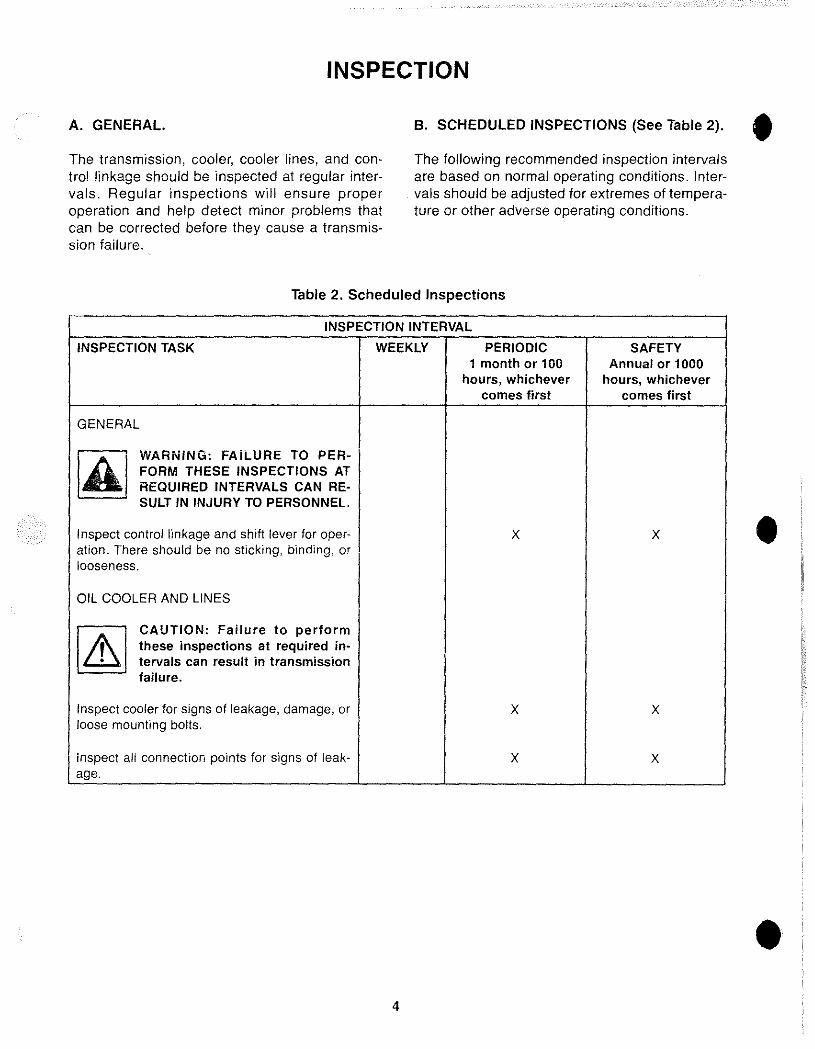
B. SCHEDULED INSPECTIONS (See Table 2).
The following recommended inspection intervals are based on normal operating conditions. Intervals should be adjusted for extremes of temperature or other adverse operating conditions.
Table 2. Scheduled Inspections
INSPECTION INTERVAL
INSPECTION TASK WEEKLY PERIODIC SAFETY 1 month or 100 Annual or 1000
hours, whichever hours, whichever comes first comes first
GENERAL
~ WARNiNG: FAilURE TO PER-FORM THESE INSPECTIONS AT REQUIRED INTERVALS CAN RE-SULT IN INJURY TO PERSONNEL.
Inspect control linkage and shift lever for oper- X X ation. There should be no sticking, binding, or looseness.
OIL COOLER AND LINES
[ZEJ CAUTION: Failure to perform these inspections at required in-tervals can result in transmission failure.
Inspect cooler for signs of leakage, damage, or X X loose mounting bolts.
inspect all connection pOints for signs of leak- X X age.
4
•
•
•
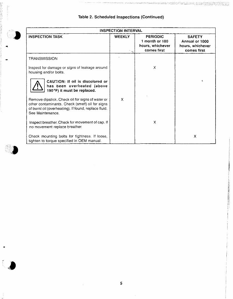
Table 2. Scheduled Inspections (Continued)
INSPECTlQN INTERVAL
INSPECTION TASK WEEKLY PERIODIC SAFETY 1 month or 100 Annual or 1000 .. hours, whichever hours, whichever
*,> comes first comes first
TRANSMISSION
Inspect for damage or signs of leakage around X housing andlor bolts.
I A I CAUTION: If oil is discolored or ,
, has been overheated (above • 190°F) it must be replaced.
Remove dipstick. Check oil for signs of water or X other contaminants. Check (smell) oil for signs of burnt oil (overheating). If found, replace fluid. See Maintenance.
Inspect breather. Check for movement of cap. If X no movement replace breather.
Check mounting bolts for tightness. If loose, X tighten to torque specified in OEM manual.
5
MAINTENANCE
A. GENERAL.
Maintenance to the transmission will normally consist of the followi ng items.
• Checking oil level or changing oil. Regular scheduled oil changes are an important part of transmission maintenance.
IAI WARNING: SHIFT LINKAGE MUST BE ADJUSTED FOR PROPER OPER-ATION OF TRANSMISSION.
NOTE: For details on each of these adjustments refer to the OEM manual.
• Checking pressure in each circuit (if a problem is detected).
CAUTION: Transmission mounting bolts should be checked and tightened to torque specified in OEM manual. Do not overtighten! Damage to the transmission can result.
B. LUBRICATION.
Due to the various installation angles and oil cooler set-ups, it may be necessary to adjust your oil level.
WARNING: DO NOT REMOVE DIPSTICK WITH ENGINE RUNNING. HOT OIL CAN CAUSE BURNS.
CAUTION: Clean around the area of the dipstick, before removing. Small particles of dirt can cause damage to internal components and cause valves to stick.
6
Check Oil Level.
The transmission should be at operating temperture (190 0 max.) to get an accurate oil level reading. Oil will expand when it is heated. Oil will drain back from the cooler. Expansion and drainback can significantly affect oil level.
Warm Oil Level Check.
When the transmission is at operating temperature, place selector lever in neutral. Shut off engine. Carefully remove transmission dipstick. Immediately insert clean dipstick and read oil level.
NOTE: Oil level must be checked immediately after engine shut-down to prevent an incorrect reading. Oil drains back into transmission from the cooler and cooler lines.
Add or remove oil if necessary. Repeat the above checking procedure as required until oil is at the dipstick mark.
Cold Oil Level Check.
For ease of checking the oil prior to engine startup, a cold oil level mark can be made. To find the cold oil level mark, the oil level must first be set according to the warm oil level checking procedure. Then, let the boat sit overnight. Insert clean dipstick and read oil level.
Put a mark on the dipstick at the cold oil level reading.
You can use the new mark to check the oil level when cold. If oil level adjustment is needed, add oil to the new mark.
•
•
•
......
r&. ... -.,
Type of Oil.
Dexron, Type F, or any hydraulic fluid which meets the C-3 oil specification is acceptable. Do not mix different brands. If engine doesn't exceed 3,000 R.P.M., a premium grade 30 weight engine oil is acceptable. SAE #40 and multiviscosity oils are not recommended.
If the transmission oil temperature has exceeded 190 0 F or the alarm sounds, the oil must be changed in the transmission and cooler system.
Changing Oil.
Oil in transmission, cooler, and cooler lines should be changed after every 1,000 hours of operation or annually. Severe service conditions or high operating temperatures may require more frequent changes.
• Place selector lever in neutral. Run engine for five minutes at 1500 RPM. Shut down engine.
CAUTION: Clean around the area of drain plug, before removing. Small particles of dirt can cause damage to internal components and cause valves to stick.
• Drain oil from transmission, cooler, and cooler lines into a suitable container .
7
• Check oil for signs of metal or rubber particles.
CAUTION: A few small metal particles are normal. However, if large metal chips or a large number of particles are found, this could be an early sign of transmission failure_ The transmission should be disassembled and inspected for internal damage.
NOTE: Particles of rubber can indicate cooler line wear. Each line should be inspected for cracks or fraying and should be replaced if damaged.
• Fill transmission with new oil.
NOTE: The amount of oil required will vary based on length of cooler lines. Use an amount equal to about three-fourths the quantity removed.
• Install dipstick. Run engine for two minutes to fill cooler and cooler lines with oil. Set oil level according to procedure at start of section S, Lubrication.
TROUBLESHOOTING
A. GENERAl.
Before troubleshooting the transmission, do the following.
• Check oil level and condition of oil. See Main· tenance section for details.
• Check transmission, oil cooler and oil cooler lines for physical damage or leakage. Correct any problem.
• Check that engine, damper plate, or drive train alignment are not causing the problem.
Refer to OEM manual or Velvet-Drive Installation Manual (Form No. 1131) for drive train alignment requirements.
Perform all pressure checks at normal operating temperature. Refer to Specification section for details. Pressure gauges used should have a range of 0-200 or 0-300 psi. They must be accurate.
B. GUIDELINES.
When troubleshooting, shift into each selector position to determine when noise or problem occurs. Determine which parts are moving. This will help pinpoint the cause. Use the following information as a guide to common problems.
8
Damper Plate. Some transmission problems are damper plate related. Check and/or replace damper plate when the following problem occurs.
• Transmission "knocks" at idle or low RPM, then stops at 1,000 RPM or higher.
If the damper plate springs are too soft the sides of the windows will wear. If the springs are too hard the splines will wear. Consult engine OEM for correct damper plate recommended.
Clutches. Check and/or replace clutches if the following problem occurs.
• Excessive engine RPM (over the rated RPM). This can indicate a slipping clutch. The slipping clutch will usually squeal.
WARNING: DO NOT OPERATE TRANSMISSION IF THE FOLLOWING CONDITION IS SUSPECTED. FAILURE TO COMPLY CAN RESULT IN PERSONAL INJURY BECAUSE TRANSMISSION CAN NOT BE DISENGAGED.
The slipping clutch will normally overheat. This can result in warped plates. In severe overheating plates can weld together. This will cause a tie up condition in transmission when the other clutch is applied.
•
•
•
Table 3. Troubleshooting (Continued)
PROBLEM CAUSE CORRECT/ON
MALFUNCTION IN BOTH • FORWARD AND REVERSE: (Cont.)
". 3" High oil temperature. Defective coolec Replace cooler.
Defective temperature sensor. Replace senSOr
4. No power, noise. Broken gear teeth - gears not Replace defective parts. meshed.
. 5. No line pressure. Heavy weight oil (90 weight). Remove and use proper weight
oil.
Pump Incorrectly indexed. Rotate pump to correct position.
Oil inlet shield or screen blocked. Inspect and clean.
6. Noisy in Forward and Reverse. Misalignment of damper plate with Align drive train components. engine, or misalignment of output snail components.
Damaged gears. Replace damaged gears.
MALFUNCTION IN FORWARD OR REVERSE: • 1 . CI utch drags or does not Warped clutch plate. Replace defective parts.
release. Mechanical failure. Replace defective parts.
Tight pack clearance. Increase clearance to specification.
2. Clutch does not apply. Low pressure. See low oil pressure.
Defective parts. Replace defective parts.
3. Harsh engagement. High pressure - valve sticking. Clean and polish regulator valve.
Engine idle too fast. Adjust engine idle.
Linkage binding or misadjusted. Repair as required and adjust to OEM spec.
4. Soil engagement. Low pressure. See low oil pressure.
5. Won't move or sluggish. Forward clutch seized. Replace defective parts.
Worn or broken sealing rings" Replace defective parts.
• 10
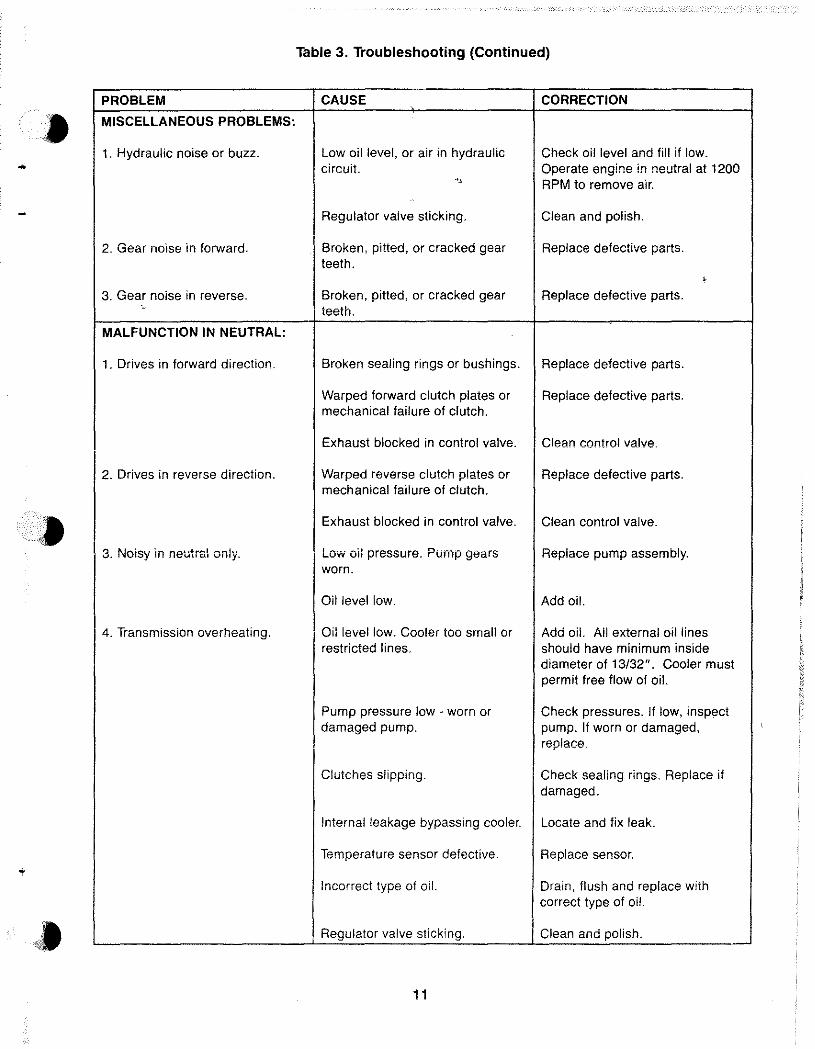
Table 3. Troubleshooting (Continued)
PROBLEM CAUSE CORRECTION
MISCELLANEOUS PROBLEMS:
1. Hydraulic noise or buzz. Low oil level. or air in hydraulic Check oil level and fill if low. - circuit. Operate engine in neutral at 1200 " RPM to remove air.
Regulator valve sticking. Clean and polish.
2. Gear noise in forward. Broken, pitted, or cracked gear Replace defective parts. teeth.
, 3. Gear noise in reverse. Broken, pitted, or cracked gear Replace defective parts.
"
teeth.
MALFUNCTION IN NEUTRAL:
1. Drives in forward direction. Broken sealing rings or bushings. Replace defective parts.
Warped forward clutch plates or Replace defective parts. mechanical failure of clutch.
Exhaust blocked in control valve. Clean control valve.
2. Drives in reverse direction. Warped reverse clutch plates or Replace defective parts. mechanical failure of clutch.
Exhaust blocked in control valve. Clean control valve.
3. Noisy in neutral only. Low oil pressure. Pump gears Replace pump assembly. worn.
Oil level low. Add oil.
4. Transmission overheating. Oil level low. Cooler too small or Add oil. All external oil lines restricted lines. should have minimum inside
diameter of 13/32". Cooler must permit free flow of oil.
Pump pressure low· worn or Check pressures. If low, inspect damaged pump. pump. If worn or damaged,
replace.
Clutches slipping. Check sealing rings. Replace if damaged.
Internal leakage bypassing cooler. Locate and fix leak.
Temperature sensor defective. Replace sensor.
Incorrect type of oil. Drain, flush and replace with correct type of oil.
Regulator valve sticking. Clean and polish.
11
OVERHAUL
A. GENERAL.
Before removal and disassembly, review the following procedures. Use the proper hand tools, slings, or hoists for the job.
WARNING: KEEP WORK AREA, TOOLS, AND TRANSMISSION CLEAN. WIPE UP ANY SPILLED TRANSMISSION FLUID TO PREVENT ACCIDENTS. AS REQUIRED, WEAR SAFETY GLASSES, SAFETY SHOES AND A HARD HAT TO PREVENT PERSONAL INJURY.
B. DISASSEMBLY.
NOTE: Read OEM Vehicle manual for specific removal instructions.
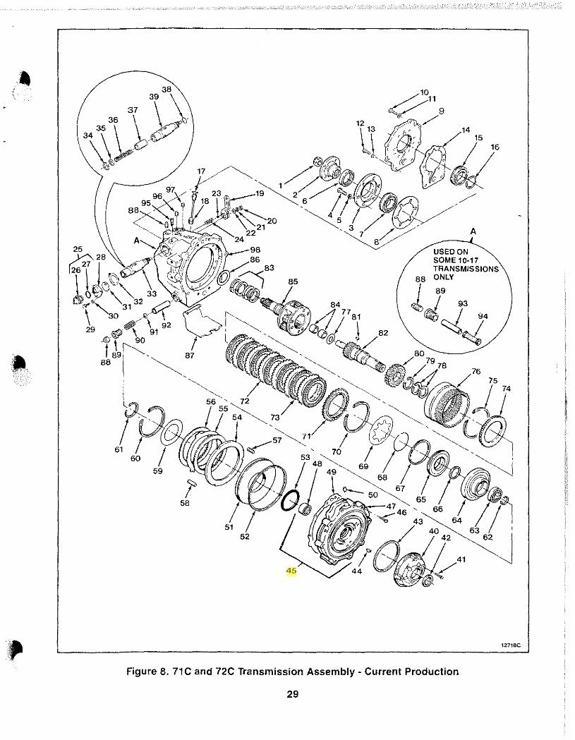
Before starting disassembly, review the exploded-view shown in Figure 8. The transmission can be disassembled following the index numbers shown in Figure 8.
Seals. Remove a-rings, sealing rings, and oil seals carefully to prevent damage if they must be reused. It is best to replace these items.
Bearings. Do not remove bearings unless replacement is required, or cleaning can not be done properly.
• Keep matched parts or sets together. Do not reverse or mix them.
C. CLEANING.
WARNING: CLEANING SOLVENTS CAN BE TOXIC, FLAMMABLE, AN IRRITANT TO THE SKIN, OR GIVE OFF HARMFUL FUMES. AVOID PRO-LONGED CONTACT, INHALATION OF VAPORS, OR SMOKING. FAILURE TO COMPLY CAN RESULT IN INJURY OR DEATH TO PERSONS.
• Rinse all metal parts in solvent to remove dirt, grease, and transmission fluid.
12
• Take special care to remove solvent from all parts.
• Air<lry clutch plates.
• If a-rings are to be reused, air dry them.
D. INSPECTION.
Case. Inspect for cracks. Check sealing surfaces for nicks, scratches, or burrs that can cause leaks. Inspect output shaft bore for signs of wear on one side. This can indicate misalignment of prop shafl.
Gears. Inspect for unusual wear patterns, chipped, cracked, or broken teeth.
Bearings. Inspect for chips, cracks, galling, or missing bearings. Check for signs of overheating.
Threaded Parts. Inspect for stripped, damaged threads, or burrs.
Springs. Inspect for distortion, cracks, or other damage. Check springs against dimensions in Specification section.
E. REPAIR.
• Remove scratches, burrs, or minor surface defects with very fine emery cloth.
• Threaded holes can be retapped USing the same size tap. Do not make the hole oversize.
• Repair or replace all damaged parts.
•
•
•
-
F. ASSEMBLY.
CAUTION: Threaded plugs, screws, , . bolts, and coupling nuts must be tigtened to the torques shown in Table 4 to prevent premature failure of transmission.
• A new coupling nut must be used at assembly.
• Prior to assembly, dip or coat internal parts with transmission fluid. Let excess fluid drain of I.
• Use B.light coat of vasoline to position or hold a gasket, O-ring, or small part for assembly. Apply to sealing rings before assembly.
• Inspect assemblies pressed together for proper fit and position.
• Check that each snap ring is fully engaged in groove.
• Threaded plugs, screws, and bolts should be tightened to the torques shown in Table 4.
NOTE: The following procedures are correct for most transmissions. Minor differences may be found on some models.
• Assemble the transmission using the following procedures. If a reduction unit is mounted to the transmission, refer to the correct sectio,n at the back of this manual for assembly procedures.
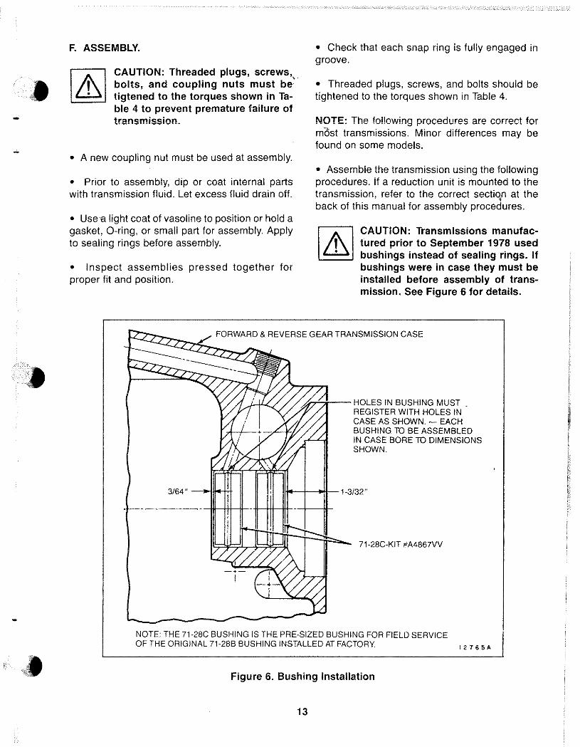
CAUTION: Transmissions manufactured prior to September 1978 used bushings instead of sealing rings. If bushings were in case they must be installed before assembly of transmission. See Figure 6 for details.
~2:;'7"~(._FORWARD & REVERSE GEAR TRANSMISSION CASE
3/64" --lO>jlJoo-trr
u,.-'-;;;-- HOLES IN BUSHING MUST . REGISTER WITH HOLES IN CASE AS SHOWN. EACH BUSHING TO BE ASSEMBLED IN CASE BORE TO DIMENSIONS SHOWN.
11;.-+-00II--1·3/32"
71·28C·KIT #A4867VV
NOTE: THE 71·28C BUSHING IS THE PRE·SIZED BUSHING FOR FIELD SERVICE OF THE ORIGINAL 71·28B BUSHING INSTALLED AT FACTORY !2765A
Figure 6. Bushing Installation
13
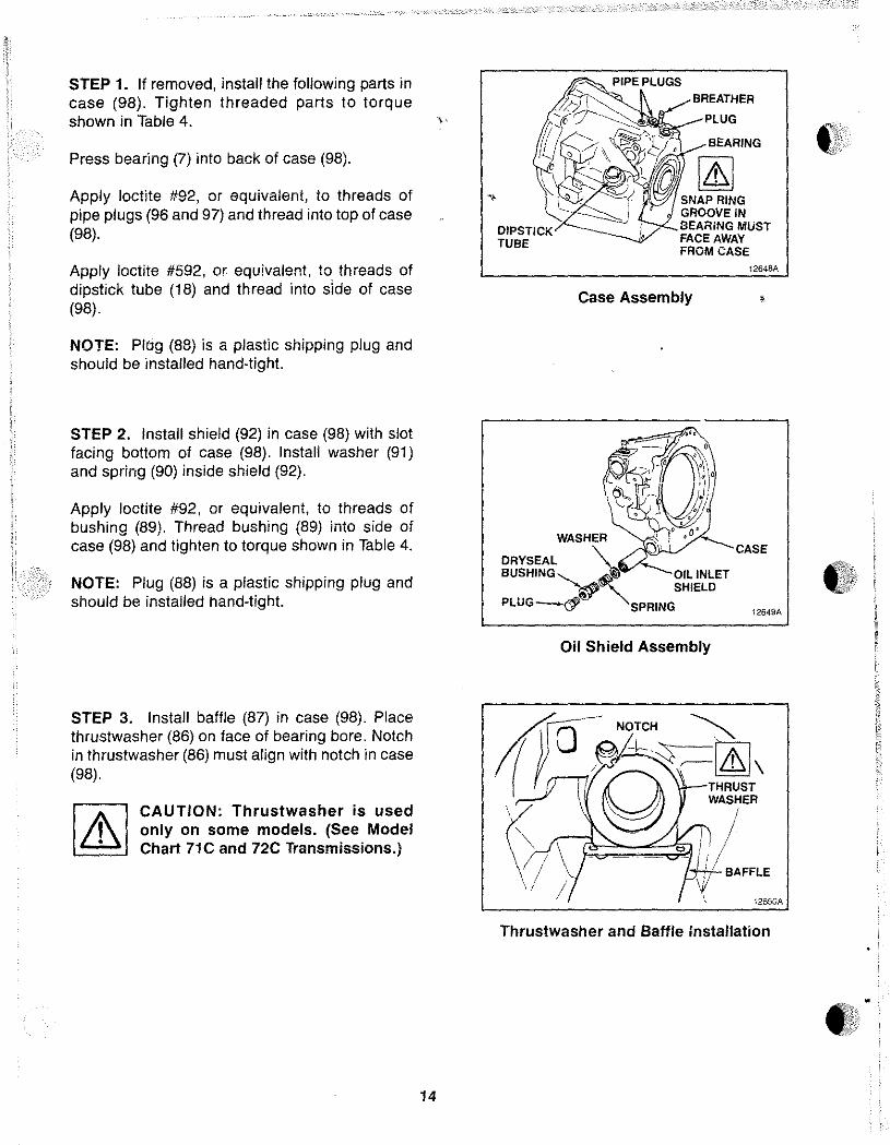
STEP 1. If removed, install the following parts in case (98). Tighten threaded parts to torque shown in Table 4. ,.
Press bearing (7) into back of case (98).
Apply loctile #92, or equivalent, to threads of " pipe plugs (96 and 97) and thread into top of case (98).
Apply loctile #592, or equivalent, to threads of dipstick tube (18) and thread into side of case (98).
NOTE: Plug (88) is a plastic shipping plug and should be installed hand-tight
STEP 2. Install shield (92) in case (98) with slot facing bottom of case (98). Install washer (91) and spring (90) inside shield (92).
Apply loctite #92, or equivalent, to threads of bushing (89). Thread bushing (89) into side of case (98) and tighten to torque shown in Table 4.
NOTE: Plug (88) is a plastic shipping plug and should be installed hand-tight
STEP 3. Install baffle (87) in case (98). Place thrustwasher (86) on face of bearing bore. Notch in thrustwasher (86) must align with notch in case (98).
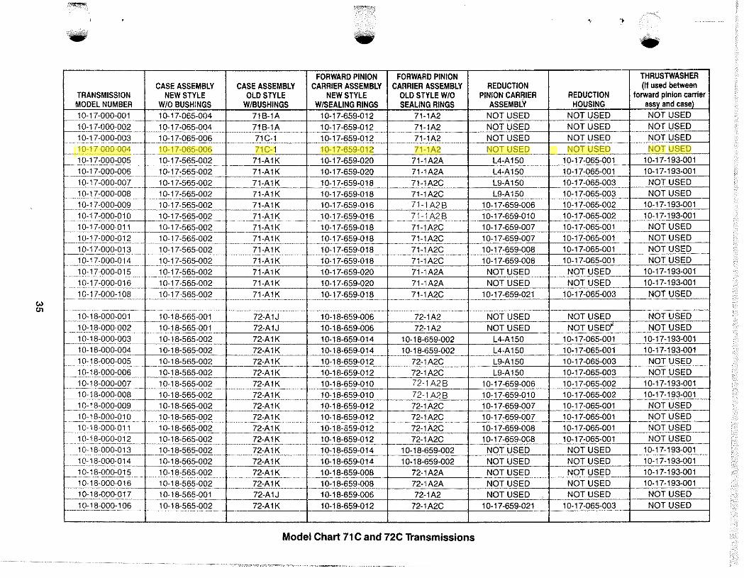
I A I CAUTION: Thrustwasher is used , only on some models. (See Model • Chart 71C and 72C Transmissions.)
14
12648A
Case Assembly
CASE DRYSEAL BUSHING -....... --"'~"" OIL INLET
~r;;J" " SHIELD PLUG-& SPRING
12649A
Oil Shield Assembly
Thrustwasher and Baffle Installation
<t
STEP 4. Lubricate sealing rings (83) and bushings (84) with vasoline.
If removed, press bushings (84) into pinion car:· rier (85).
CAUTION: Do not block pressure holes in pinion carrier (85) with bushings (84).
Install sealing rings (83) in grooves of pinion carrier (85). Compress each sealing ring (83) until it locks in place.
Install pinion carrier (85) in case (98).
STEP 5. Install pressure plate (74) in ring gear (76).
STEP 6. Starting with a friction clutch plate (73), alternately stack friction clutch plates (73) and steel clutch plates (72).
Place pressure plate (71) on top of clutch plates (72 and 73).
15
GEAR
SEALING RINGS
12666A
Pinion Carrier Assembly
EXTERNAL SPLINES
Pressure Plate Assembly
STEEL CLUTCH PLATE
PRESSURE PLATE
11829A
11830A
Forward Clutch Pack Arrangement
STEP 7. Install clutch plates (72 and 73) and pressure plate (71) in ring gear (76).
STEP 8. Install snap ring (70) in ring gear (76).
CAUTION: Several different snap rings are used to assemble the clutch group. They have different thicknesses. Be sure the correct snap ring is used.
STEP 9. Lubricate O-ring (66) Iigbtly with vasoline and install in groove of forward clutch cylinder (64).
16
PRESSURE PLATE
11831A
Forward Clutch Pack Assembly
SNAP RING
RING GEAR
PRESSURE PLATE
11832A
Snap Ring Insta"ation
O-RING FORWARD CLUTCH CYLINDER
O-Ring Insta"ation
11833A
•
•
•
••
STEP 10. Lubricate clutch spring bearing ring (68) and piston sealing ring (67) with vasoline.
'" Install clutch spring bearing ring (68) in groove on piston (65) face.
Install piston sealing ring (67) in outer groove of piston (65),
NOTE: Check that piston sealing ring (67) is not twisted, cut, or deformed. Replace if damaged.
STEP 11. Install piston (65) in forward clutch cylinder (64).
STEP 12. Place clutch belleville (dish) spring (69) inside rim of forward clutch cylinder (64). Spring is dished. The inside of the spring should be lower than the outside.
17
CLUTCH SPRING BEARING RING
PISTON SEALING RING
PISTON
Clutch Rings Installation ,
Piston Installation
12651A
CLUTCH BELLEVILLE SPRING (DISHED)
FORWARD CLUTCH CYLINDER
Clutch Spring Assembly
11836A
STEP 13. Install ring gear (76) over forward clutch cylinder (64). with piston (65) and spring (69) facing up. Press ring gear (76) down over forward clutch cylinder (64).
[4J CAUTION: Check to see that clutch If' spring bearing ring (68) is still seated ~ in the groove of clutch piston (65).
STEP 14. Remove clutch assembly from press. Install snap ring (60) in groove of ring gear (76).
CAUTION: Several different snap rings are used to assemble the clutch group. They have different thicknesses. Be sure the correct snap ring is used.
STEP 15. Place ring gear (76) in press with external splines facing down. Assembly tool should support the ring gear (76) only. The forward clutch cylinder (64) should not be touching the assembly tool. Press forward clutch cylinder (74) against snap ring (60). Remove clutch assembly from press.
18
RING GEAR
EXTERNAL TEETH
FORWARD CLUTCH CYLINDER
12652A
Forward Clutch Cylinder Installatio!l
SNAP RING
RING GEAR
SPLINES
11838A
Snap Ring Installation
RING GEAR
TOOL
RIMOF CLUTCH CYLINDER
11837A
Compressing Clutch Pack
t)
••
•
>
••••••
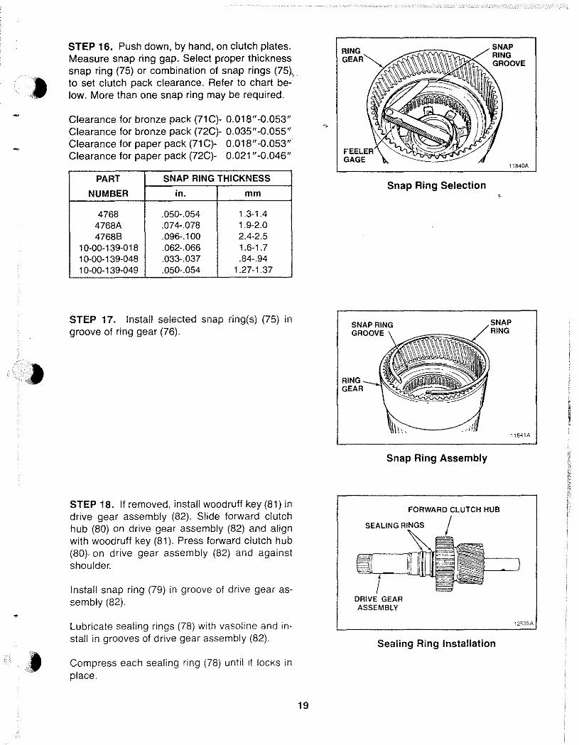
STEP 16. Push down, by hand, on clutch plates. Measure snap ring gap. Select proper thickness snap ring (75) or combination of snap rings (75~. to set clutch pack clearance. Refer to chart below. More than one snap ring may be required.
Clearance for bronze pack (71 C)- 0.018"-0.053" Clearance for bronze pack (72C)- 0.035"-0.055" Clearance for paper pack (71 C)- 0.018"-0.053" Clearance for paper pack (72C)- 0.021 "-0.046"
PART SNAP RING THICKNESS
NUMBER in. mm
4768 .050-.054 1.3-1.4 4768A .074-.078 1.9-2.0 47688 .096-.100 2.4-2.5
10-00-139-018 .062-.066 1.6-1.7 10-00-139-048 .033-.037 .84-.94 10-00-139-049 .050-.054 1.27-1.37
STEP 17. Install selected snap ring(s) (75) in groove of ring gear (76).
STEP 18. If removed, install woodruff key (81) in drive gear assembly (82). Slide forward clutch hub (80) on drive gear assembly (82) and align with woodruff key (81). Press forward clutch hub (80)- on drive gear assembly (82) and against shoulder.
Install snap ring (79) in groove of drive gear assembly (82).
Lubricate sealing rings (78) with vasoline and install in grooves of drive gear assembly (82).
Compress each sealing ring (78) until it locks in place.
19
SNAP RING
~~~~~~~ GROOVE
Snap Ring Selection
SNAP RING GROOVE
RING --.-"""' GEAR
Snap Ring Assembly
11840A
SNAP RING
11841A
FORWARD CLUTCH HUB
DRIVE GEAR ASSEMBLY
Sealing Ring Installation
1263SA
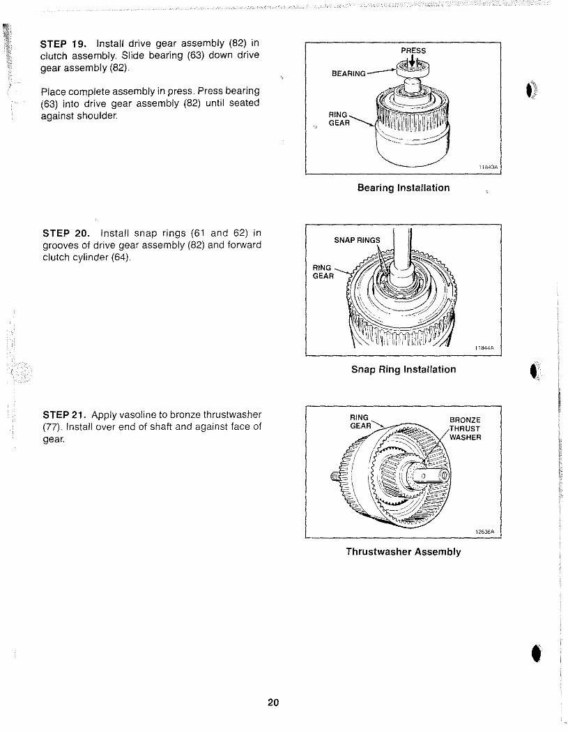
STEP 19. Install drive gear assembly (82) in clutch assembly. Slide bearing (63) down drive gear assembly (82).
Place complete assembly in press. Press bearing (63) into drive gear assembly (82) until seated against shoulder.
STEP 20. Install snap rings (61 and 62) in grooves of drive gear assembly (82) and forward clutch cylinder (64).
STEP 21. Apply vasoline to bronze thrustwasher (77). Install over end of shaft and against face of gear.
20
GEAR
RING GEAR
Bearing Installation
Snap Ring Installation
RING
GEAR~'>;~~~
Thrustwasher Assembly
11843A
11844A
••
12636A
•
•
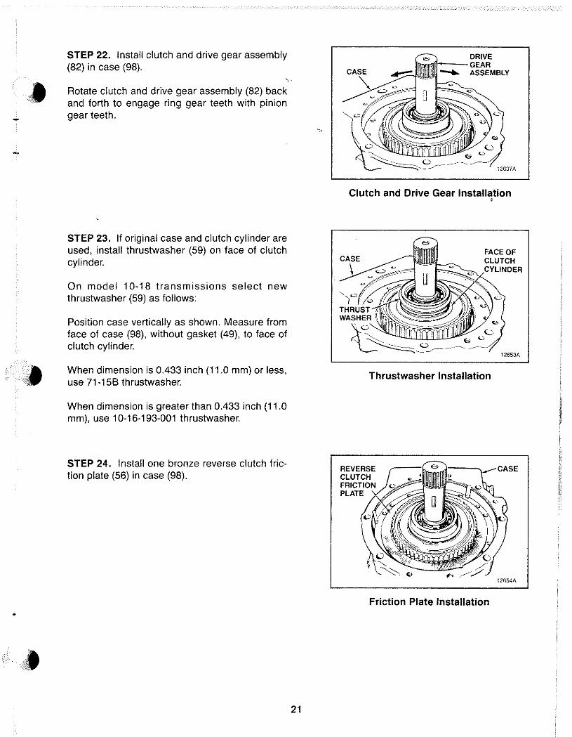
STEP 22. Install clutch and drive gear assembly (82) in case (98).
Rotate clutch and drive gear assembly (82) back and forth to engage ring gear teeth with pinion gear teeth.
STEP 23. If original case and clutch cylinder are used, install thrustwasher (59) on face of clutch cylinder.
On model 10-18 transmissions select new thrustwasher (59) as follows:
Position case vertically as shown. Measure from face of case (98), without gasket (49), to face of clutch cylinder.
When dimension is 0.433 inch (11.0 mm) or less, use 71-158 thrustwasher.
When dimension is greater than 0.433 inch (11.0 mm), use 10-16-193-001 thrustwasher.
STEP 24. Install one bronze reverse clutch friction plate (56) in case (98).
21
DRIVE
ASSEMBLY
Clutch and Drive Gear Installation
CASE
,
FACE OF CLUTCH
12653A
Thrustwasher Installation
Friction Plate Installation
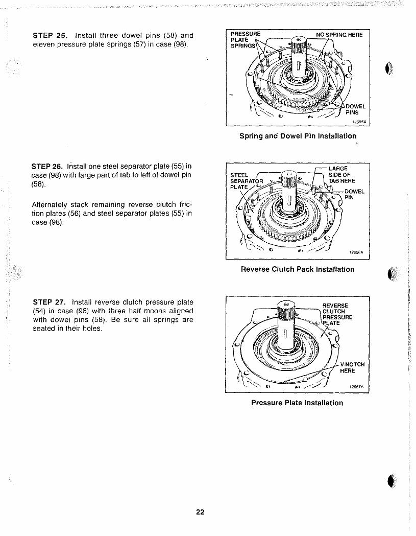
STEP 25. Install three dowel pins (58) and eleven pressure plate springs (57) in case (98).
STEP 26. Install one steel separator plate (55) in case (98) with large part of tab to left of dowel pin (58).
Alternately stack remammg reverse clutch friction plates (56) and steel separator plates (55) in case (98).
STEP 27. Install reverse clutch pressure plate (54) in case (98) with three half moons aligned with dowel pins (58). Be sure all springs are seated in their holes.
22
PRESSURE HERE PLATE
12655A
Spring and Dowel Pin Installation
Reverse Clutch Pack Installation
V-NOTCH HERE
12657A
Pressure Plate Installation
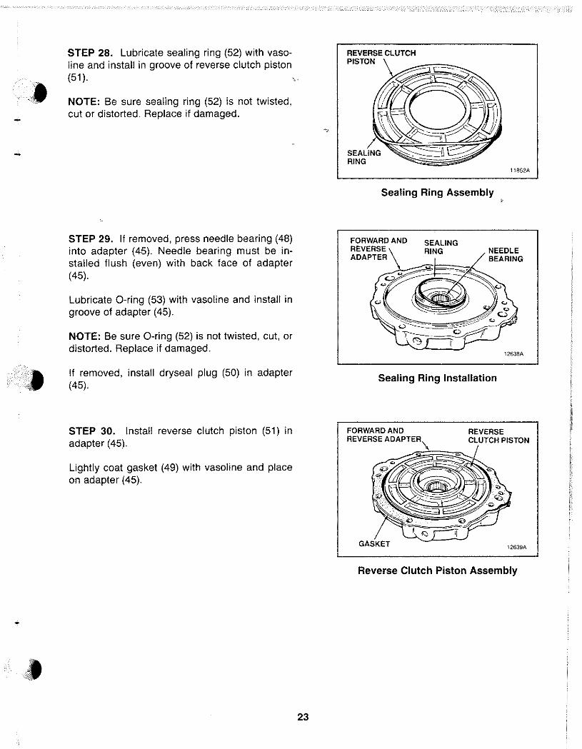
STEP 28. Lubricate sealing ring (52) with vasoline and install in groove of reverse clutch piston (51). ,
NOTE: Be sure sealing ring (52) is not twisted, cut or distorted. Replace if damaged.
STEP 29. If removed, press needle bearing (48) into adapter (45). Needle bearing must be installed flush (even) with back face of adapter (45).
Lubricate O-ring (53) with vasoline and install in groove of adapter (45).
NOTE: Be sure O-ring (52) is not twisted, cut, or distorted. Replace if damaged.
If removed, install dryseal plug (50) in adapter (45).
STEP 30. Install reverse clutch piston (51) in adapter (45).
Lightly coat gasket (49) with vasoline and place on adapter (45).
23
11852A
Sealing Ring Assembly
FORWARD AND SEALING REVERSE RING ADAPTER
NEEDLE BEARING
12638A
Sealing Ring Installation
FORWARD AND REVERSE ADAPTER\
~~~
REVERSE CLUTCH PISTON
12639A
Reverse Clutch Piston Assembly
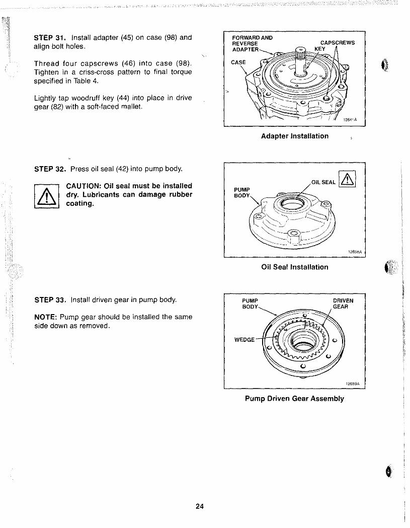
STEP 31. Install adapter (45) on case (98) and align bolt holes.
Thread four capscrews (46) into case (98). Tighten in a criss-cross pattern to final torque specified in Table 4.
Lightly tap woodruff key (44) into place in drive gear (82) with a soft-faced mallet.
STEP 32. Press oil seal (42) into pump body.
I A I CAUTION: Oil seal must be installed , dry. Lubricants can damage rubber • coating.
FORWARD AND REVERSE
Adapter Installation
12641A
OIL SEAL IAI
12658A
Oil Seal Installation «If
STEP 33. Install driven gear in pump body. DRIVEN
NOTE: Pump gear should be installed the same side down as removed.
24
GEAR
WEDGE
i2659A
Pump Driven Gear Assembly
•
»
• ...•.. '
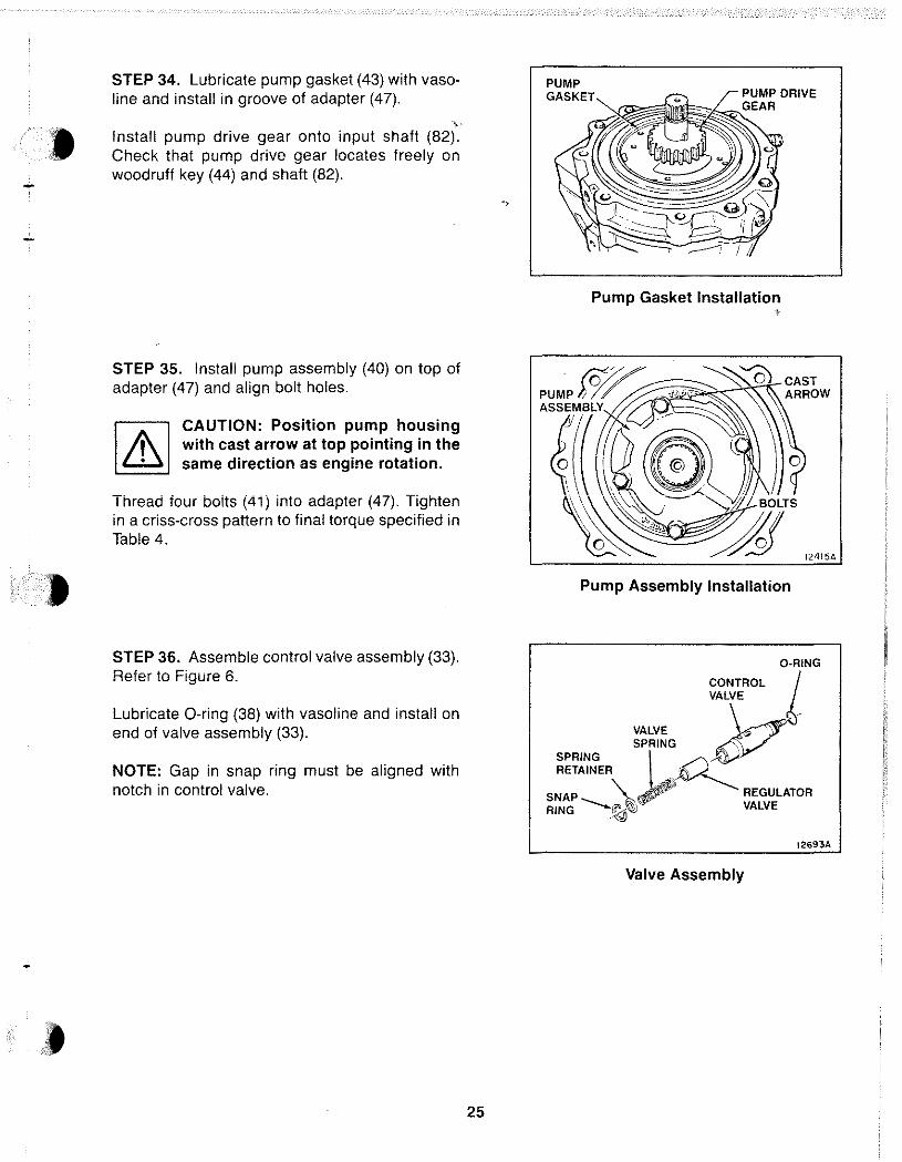
STEP 34. Lubricate pump gasket (43) with vasoline and install in groove of adapter (47).
, Install pump drive gear onto input shaft (82). Check that pump drive gear locates freely on woodruff key (44) and shaft (82).
STEP 35. Install pump assembly (40) on top of adapter (47) and align bolt holes.
[4] CAUTION: Position pump housing Ii' with cast arrow at top pointing in the
~ same direction as engine rotation.
Thread four boits (41) into adapter (47). Tighten in a criss-cross pattern to final torque specified in Table 4.
STEP 36. Assemble control valve assembly (33). Refer to Figure 6.
Lubricate O-ring (38) with vasoline and install on end of valve assembly (33).
NOTE: Gap in snap ring must be aligned with notch in control valve.
25
PUMP GASKET
Pump Gasket Installation ,
Pump Assembly Installation
O-RING
CONTROL /
VALVE & VALVE ~ SPRING .
SPRING J~' ~.' RETAINER ~
SNAP \..~ REGULATOR RING ~~ VALVE
12693A
Valve Assembly
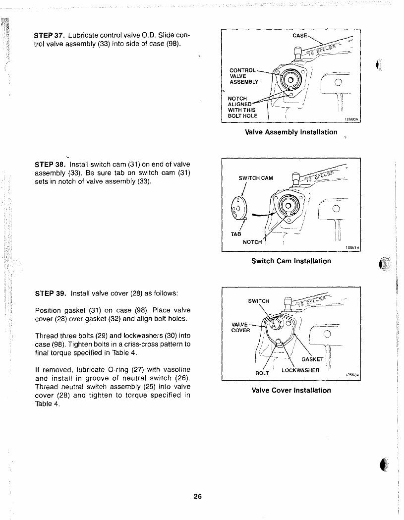
STEP 37. Lubricate control valve 0.0. Slide control valve assembly (33) into side of case (98).
STEP 38. Install switch cam (31) on end of valve assembly (33). Be sure tab on switch cam (31) sets in notch of valve assembly (33).
STEP 39. Install valve cover (28) as follows:
Position gasket (31) on case (98). Place valve cover (28) over gasket (32) and align bolt holes.
Thread three bolts (29) and lockwashers (30) into case (98). Tighten bolts in a criss-cross pattern to final torque specified in Table 4.
If removed, lubricate O-ring (27) with vasoline and install in groove of neutral switch (26). Thread neutral switch assembly (25) into valve cover (28) and tighten to torque specified in Table 4.
26
CONTROL VALVE ASSEMBLY
NOTCH ALiGNEO WITH THIS BOLT HOLE
CASE
Valve Assembly Installation
SWITCH CAM
I (f0 I()j, --''''\
I TAB
NOTCH
Switch Cam Installation
SWITCH
VALVE_..!..!\C COVER
BOLT
o ) ~~~_-.. III 0
,I
GASKET •• : i
LOCKWASHER I i
Valve Cover Installation
12661A
12662A
t ,ti~ I
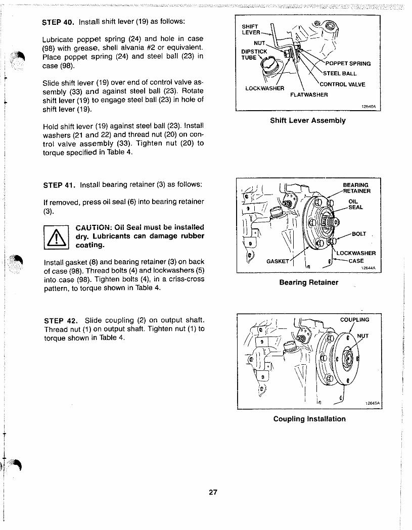
STEP 40. Install shift lever (19) as follows:
Lubricate poppet spring (24) and hole in case (98) with grease, shell alvania #2 or equivalent. Place poppet spring (24) and steel ball (23) in case (98).
Slide shift lever (19) over end of control valve assembly (33) and against steel ball (23). Rotate shift lever (19) to engage steel ball (23) in hole of shift lever (19).
Hold shift lever (19) against steel ball (23). Install washers (21 and 22) and thread nut (20) on control valve assembly (33). Tighten nut (20) to torque specified in Table 4.
STEP 41. Install bearing retainer (3) as follows:
If removed, press oil seal (6) into bearing retainer (3).
CAUTiON: Oil Seal must be installed dry. Lubricants can damage rubber coating.
Install gasket (8) and bearing retainer (3) on back of case (98). Thread bolts (4) and lockwashers (5) into case (98). Tighten bolts (4), in a criss-cross pattern, to torque shown in Table 4.
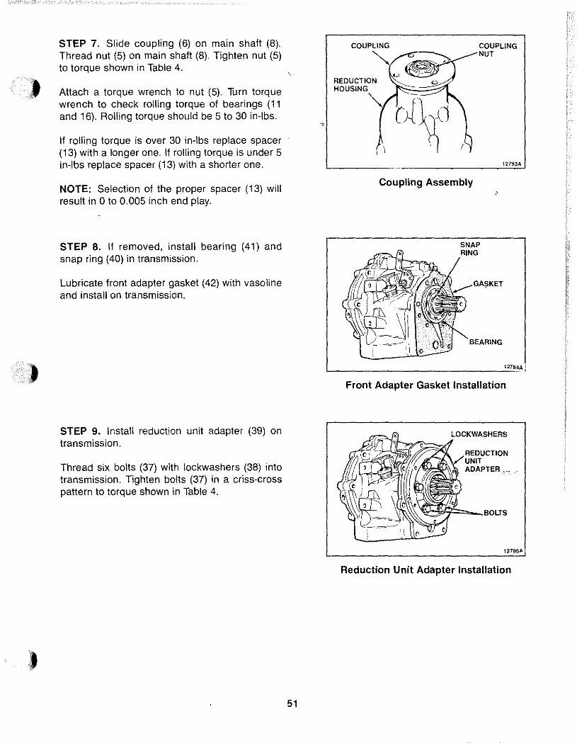
STEP 42. Slide coupling (2) on output shaft. Thread nut (1) on output shaft. Tighten nut (1) to torque shown in Table 4.
27
/\~~~ \\_-'1..., ~ '\" :::.-1 '5{1
- j}
SHIFT LEVER
NUT ~~4\1"111
DIPSTICK > TUBE~ POPPET SPRING
STEEL BALL
LOCKWASHER CONTROL VALVE
\ FLATWASHER
Shift Lever Assembly
12640A
BEARING
OIL
12644A
Bearing Retainer
12645A
Coupling Installation
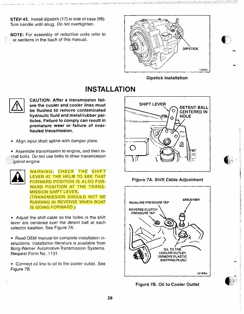
STEP 43. Install dipstick (17) in side of case (98). Turn handle until snug. Do not overtighten.
NOTE: For assembly of reduction units refer to le sections in the back of this manual.
DIPSTICK
12663A
Dipstick Installation
INSTALLATION CAUTION: After a transmission failure the cooler and cooler lines must be flushed to remove contaminated hydraulic fluid and metal/rubber particles. Failure to comply can result in premature wear or failure of overhauled transmission.
• Align input shaft spline with damper plate.
• Assemble transmission to engine, and then in· "tall bolts. Do not use bolts to draw transmission .gainst engine.
WARNING: CHECK THE SHIFT LEVER AT THE HELM TO SEE THAT FORWARD POSITION IS ALSO FORWARD POSITION AT THE TRANSMISSION SHIFT LEVER. (TRANSMISSION SHOULD NOT BE RUNNING IN REVERSE WHEN BOAT IS GOING FORWARD.)
• Adjust the shift cable so the holes in the shift lever are centered over the detent ball at each selector lo~ation. See Figure 7A.
• Read OEM manual for complete installation instructions. Installation literature is available from Borg-Warner Automotive-Transmission Systems. Request Form No. 1131.
• Connect oil line to oil to the cooler outlet. See Figure 7B.
28
SHIFT LEVER
=:::::::::--.- " 0 -~~ _ =-------=:: \ - 0
DETENT BALL CENTERED IN HOLE
Figure 7A. Shift Cable Adjustment
BREATHER MAINLINE PRESSURE TAP
REVERSE CLUTCH ~ PRESSURE TAP
~~~~
I REMOVE PLASTIC SHIPPING PLUG J
1278~A
Figure 7B. Oil to Cooler Outlet
38
39 \
37 \
3536 \ p'" ~~~o
58
45
USEDON SOME 10-17 TRANSMISSIONS i8 ~:LY
~ J 93
~~~4
Figure 8. 71C and 72C Transmission Assembly - Current Production
29
12718C
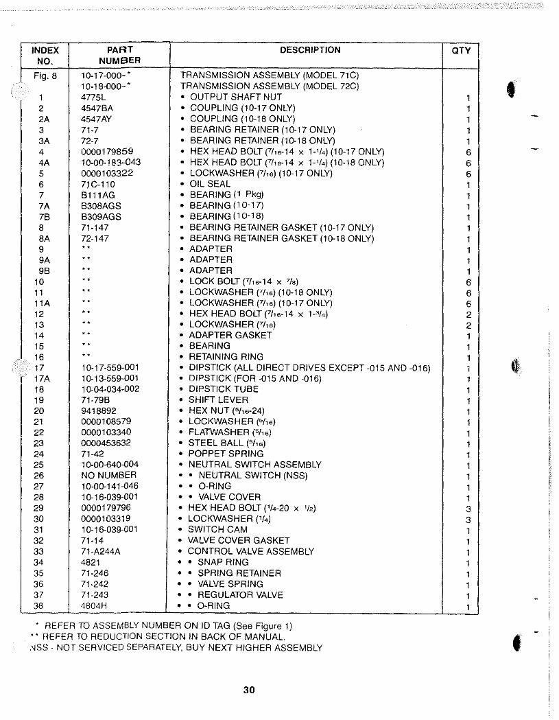
INDEX PART DESCRIPTION NO. NUMBER
Fig. 8 10·17-000- • TRANSMISSION ASSEMBLY (MODEL 71C) 10-18-000- • TRANSMISSION ASSEMBLY (MODEL 72C)
1 4775L • OUTPUT SHAFT NUT 2 4547BA • COUPLING (10-17 ONLY) 2A 4547AY • COUPLING (10-18 ONLY) 3 71-7 • BEARING RETAINER (10-17 ONLY) 3A 72-7 • BEARING RETAINER (10-18 ONLY) 4 0000179859 • HEX HEAD BOLT (711a-14 X 1_11.) (10-17 ONLY) 4A 1 0-00-183-043 • HEX HEAD BOLT FI1a-14 x 1-1/4) (10-18 ONLY) 5 0000103322 • LOCKWASHER (711a) (10-17 ONLY) 6 7)C-110 • OIL SEAL 7 B111AG • BEARING (1 Pkg) 7A B308AGS • BEARING (10-17) 7B B309AGS • BEARING (10-18) 8 71-147 • BEARING RETAINER GASKET (10-17 ONLY) 8A 72-147 • BEARING RETAINER GASKET (10-18 ONLY) 9 .. • ADAPTER 9A .. • ADAPTER 9B .. • ADAPTER
10 .. • LOCK BOLT (711a-14 x 7/8 )
11 .. • LOCKWASHER (7/1a) (10-18 ONLY) 11A .. • LOCKWASHER (7/1a) (10-17 ONLY) 12 .. • HEX HEAD BOLT (7/,a-14 x P/4) 13 .. • LOCKWASHER (711a) 14 .. • ADAPTER GASKET 15 .. • BEARING 16 .. • RETAINING RING 17 10-17-559-001 • DIPSTICK (ALL DIRECT DRIVES EXCEPT -015 AND -016) 17A 1 0-13-559-001 • DIPSTICK (FOR -015 AND -016) 18 1 0-04-034-002 • DIPSTICK TUBE 19 71-79B • SHIFT LEVER 20 9418892 • HEX NUT (5/'a-24) 21 0000108579 • LOCKWASHER (5/1a) 22 0000103340 • FLATWASHER (5116) 23 0000453632 • STEEL BALL (5/16) 24 71-42 • POPPET SPRING 25 1 0-00-640-004 • NEUTRAL SWITCH ASSEMBLY 26 NO NUMBER • • NEUTRAL SWITCH (NSS) 27 10-00-141-046 • • O-RING 28 10-16-039-001 • • VALVE COVER 29 0000179796 • HEX HEAD BOLT ('/4-20 X 1/2) 30 0000103319 • LOCKWASHER ('/4) 31 1 0-16-039-001 • SWITCH CAM 32 71-14 • VALVE COVER GASKET 33 71-A244A • CONTROL VALVE ASSEMBLY 34 4821 • • SNAP RING 35 71-246 • • SPRING RETAINER 36 71-242 • • VALVE SPRING 37 71-243 • • REGULATOR VALVE 38 4804H • • O-RING
• REFER TO ASSEMBLY NUMBER ON 10 TAG (See Figure 1) ., REFER TO REDUCTION SECTION IN BACK OF MANUAL. ,'ISS - NOT SERVICED SEPARATELY, BUY NEXT HIGHER ASSEMBLY
30
QTY
1 • 1 1 1 1 6 6 6 1 1 1 1 1 1 1 1 1 6 6 6 2 2 1 1 1 1 1 1 1 1 1 1 1 1 1 1 1 1 3 3 1 1 1 1 1 1 1 1
•
INDEX PART DESCRIPTION aTY NO. NUMBER
39 71·244A • • CONTROL VALVE 1 40 71 C-A60 • PUMP ASSEMBLY 1 41 1 0·00·183-021 • HEX HEAD BOLT (S"6·18 x 1.318) 4 42 1 0-00-044-014 • • OIL SEAL 1 43 3-61 • PUMP GASKET 1 44 4873 • WOODRUFF KEY 1 45 71 C-A8 • FORWARD AND REVERSE ADAPTER ASSEMBLY 1 46 4911 • CAPSCREW (3fa-16 x P14) 4 47 NO NUMBER • • FORWARD AND REVERSE ADAPTER (NSS) 1 48 48400 • • NEEDLE BEARING 1 49 71-144B • GASKET 1 50 0000444858 • PIPE PLUG (114) 1 51 71·35 • REVERSE CLUTCH PISTON 1 52 4805A • CLUTCH SEALING RING 1 53 4804G • O-RING 1 54 71·71 • REVERSE CLUTCH PRESSURE PLATE 1 55 72-176 • STEEL CLUTCH PLATE 0-2 56 72-A66B • FRICTION CLUTCH PLATE 1-3 57 71-97 • PRESSURE PLATE SPRING 11 58 71-87A • DOWEL PIN (.312 DIA x .438 LONG) 3 58A R6-177 • DOWEL PIN (.312 DIA x .621 LONG) 3 588 4622E • DOWEL PIN (.312 DIA x .875 LONG) 3 59 71-158 • THRUSTWASHER 1 59A 10-16·193-001 • THRUSTWASHER 1 60 4822 • SNAP RING 1 61 R6A·7'i2 • SNAP RING (10-17 ONLY) 1 61A 4766B • SNAP RING (10-18 ONLY) 1 62 4734 • SNAP RING (10-17 ONLY) 1 62A 4559A • SNAP RING (10-18 ONLY) 1 63 B107A • BEARING (10-17 ONLY) 1 63A B108A • BEARING (iO-18 ONLY) 1 64 71-70 • FORWARD CLUTCH CYLINDER (10-17 ONLY) 1 64A 72·70 • FORWARD CLUTCH CYLINDER (10-18 ONLY) 1 65 10-16-124·001 • FORWARD CLUTCH PISTON 1 65A 71-45 • FORWARD CLUTCH PISTON 1 66 5M·122 • O-RING 1 67 5L-36 • PISTON SEALING RING 1 68 5C-33 • CLUTCH SPRING BEARING RING 1 69 3·37 • CLUTCH BELLEVILLE SPRING 1 70 4755 • SNAP RING 1 71 5C-175A • CLUTCH PRESSURE PLATE 1 72 3·176 • STEEL CLUTCH PLATE (10-17 ONLY) 4 72A 3·176 • STEEL CLUTCH PLATE (10·18 ONLY) 6 73 5C·A66A • FRICTION CLUTCH PLATE (10·17 ONLY) 5 73A 5C-A66A • FRICTION CLUTCH PLATE (10-18 ONLY) 7 74 5L-67 • CLUTCH PRESSURE PLATE 1 75 10·00-139·048 • SNAP RING (.033·.037 THICK) (10·17 ONLY) (Yellow) 1 75A 10-00-139-049 • SNAP RING (.050-.054 THICK) (10·17 ONLY) (Pink) 1 75B 4768 • SNAP RING (.050-.054 THICK) (10-18 ONLY) (Green) 1-2 75C 4768A • SNAP RING (.074-.078 THICK) (10-18 ONLY) (Orange) 1 750 4768B • SNAP RING (.096-.100 THICK) (1O-1S ONLY) (White) 1 75E 10-00-139-018 • SNAP RING (.062-.066 THICK) (iO-i8 ONLY) (Purple) 1
_ NSS - NOT SERVICED SEPARATELY. BUY NEXT HIGHER ASSEMBLY.
31
INDEX PART DESCRIPTION aTY NO. NUMBER
76 71·6 • RING GEAR (10-17 ONLY) 1 76A 72-6 • RING GEAR (10-18 ONLY) 1 77 71-17 • THRUSTWASHER 1 78 4806J • SEALING RING 2 79 4495 • SNAP RING 1 80 71-40 • FORWARD CLUTCH HUB (10-17 ONLY) 1 80A 10-16-179-001 • FORWARD CLUTCH HUB (10-18 ONLY) 1 81 0000218211 • WOODRUFF KEY (10-17 ONLY) 1 81A 0000124553 • WOODRUFF KEY (10-18 ONLY) 1 82 71C-3A16 • DRIVE GEAR ASSEMBLY (10-17 ONLY) 1 82A 72C-2A16 • DRIVE GEAR ASSEMBLY (10-18 ONLY) 1 83 4806B • SEALING RING 4 84 A4867DD (KIT) • BUSHING 2 85 10-17-659-·' • • PINION CARRIER ASSEMBLY (10-17 ONLY) 1 85A 10-18-659- ••• • PINION CARRIER ASSEMBLY (10-18 ONLY) 1 86 71-159 • THRUSTWASHER (USE W/BUSHING STYLE CASE) 1 86A 10-17-193-001 • THRUSTWASHER (USE W/SEALING RING STYLE CASE) 1 87 71-140 • OIL BAFFLE 1 87A 71B-140 • OIL BAFFLE 1 88 10-00-191-002 • PLUG (3/8-18) 2 89 4885B • DRYSEAL BUSHING (314-14) 1 90 5L-222 • SPR!NG 1 91 35-143 • FLAT WASHER 1 92 72C-98 • OIL INLET SHIELD 1 93 71C-84 • OIL RETURN TUBE 1 94 71C-A98 • OIL STRAINER ASSEMBLY 1 95 A4740G • BREATHER 1 96 0000444866 • PIPE PLUG (3/8-18) 1 97 0000444687 • PIPE PLUG ('/8-27) 1 98 10-17-565-·' • • CASE (10-17 ONLY) 1 98A 1 0-18-565- ••• • CASE (10-18 ONLY) 1
.,. CHECK MODEL CHART TO DETERMINE CORRECT PART NUMBER
NOTE: The following kits are available for the Model71C and 72C transmissions. Index numbers shown match the index numbers on the exploded-view, Figure 8.
INDEX PART DESCRIPTION aTY NO. NUMBER
A4867AB FORWARD CLUTCH PACK KIT (10-18 ONLY) 71 5C-17SA • CLUTCH PRESSURE PLATE 1 72A 3-176 • STEEL CLUTCH PLATE 6 73A 5C-A66A • FRICTION CLUTCH PLATE 7 74 SL-67 • CLUTCH PRESSURE PLATE 1
32
•
INDEX PART DESCRIPTION OTY NO. NUMBER
A4867AE FORWARD CLUTCH PACK KIT (10-17 ONLY) 71 5C-175A • CLUTCH PRESSURE PLATE 1 72 3-176 • STEEL CLUTCH PLATE 4 73 5C-A66A • FRICTION CLUTCH PLATE 5 74 5L-67 • CLUTCH PRESSURE PLATE 1
INDEX PART DESCRIPTION OTY NO. NUMBER
A4867HA OIL SEAL AND SEALING RING KIT 6 71C-l10 • OIL SEAL 1
38 4804H • O-RING 1 42 1 0-00-044-014 • OIL SEAL 1 43 3-61 • PUMP GASKET 1 52 4805A • CLUTCH SEALING RING 1 53 4804G • O-RING 1 66 5M-122 • O-RING 1 67 5L-36 • CLUTCH SEALING RING 1 78 4806J • SEALING RING 2 83 48068 : SEALING RiNG 4
1 0-00-044-01 7 • OIL SEAL (REDUCTION UNITS ONLY) 1 10-17-410-002 • SERVICE GASKET KIT (FOR CONTENTS SEE 1
NEXT KIT LIST)
INDEX PART DESCRIPTION QTY NO. NUMBER
10-17-410-002 SERVICE GASKET KIT 8 71-147 • BEARING RETAINER GASKET (10-17 ONLY) 1 8A 72-147 • BEARING RETAINER GASKET (10-18 ONLY) 1
14 L4-146 • ADAPTER GASKET 1 32 71-14 • VALVE COVER GASKET 1 49 71-144B • GASKET 1
L4-145 • GASKET (REDUCTION UNITS ONLY) 1 L4-147 • GASKET (REDUCTION UNITS ONLY) 1
INDEX PART DESCRIPTION OTY NO. NUMBER
10-04-420-052 NEUTRAL SWITCH KIT 10-04-539-001 • SWITCH AND BODY ASSEMBLY 1
25 1 0-00-640-004 • • NEUTRAL SWITCH ASSEMBLY 1 28 1 0-1 6-039-001 • • VALVE COVER 1 29 0000179796 • HEX HEAD BOLT ('/4-20 X '/2) 3 30 0000103319 • LOCKWASHER ('/4) 3 31 1 0-16-099-00 1 • SWITCH CAM 1 32 71-14 • VALVE COVER GASKET 1
1340 • INSTRUCTION SHEET 1
33
INDEX PART DESCRIPTION aTY NO. NUMBER
10-95-41 0-002 SNAP RING SERVICE KIT 15 4766 • RETAINING RING 1 34 4821 • SNAP RING 1 60 4822 • SNAP RING 1 61 R6A-7' /2 • SNAP RING (10-17 ONLY) 1 61A 47668 • SNAP RING (10-18 ONLY) 1 62 4734 • SNAP RING (10-17 ONLY) 2 62A 4559A • SNAP RING (10-18 ONLY) 1 70 4755 • SNAP RING 1 75 10-00-139-048 • SNAP RING (.033-.037 THICK)(lO-17 ONLY) (Yellow) 1 75A 10-00-139-049 • SNAP RING (.050-.054 THICK)(1 0-17 ONLY) (Pink) 1 758 4768 • SNAP RING (.050-.054 THICK)(10-18 ONLY) (Green) 2 75C 4768A • SNAP RING (.074-.078 THICK)(10-18 ONLY) (Orange) 1 75D 47688 • SNAP RING (.096-.100 THICK)(10-18 ONLY) (White) 1 75E 10-00-139-018 • SNAP RING (.062-.066 THICK)(10-18 ONLY) (Purple) 1 79 4495 • SNAP RING 1
4756D • SNAP RING (REDUCTION UNITS ONLY) 1 4756E • SNAP RING (REDUCTION UNITS ONLY) 1 4816 • SNAP RING (REDUCTION UNITS ONLY) 1 4766A • SNAP RING (REDUCTION UNITS ONLY) 1
• 34
'" (J'I
,~,
·.·.1
TRANSMISSION MODEL NUMBER 10-17-000-001 -------------- -10-17-000-002
------------------ ----,,~.. -'" --10-17-000-003 ,-- - - ~, .. " -- --.--~--- --10-17-000-004 .,,-- ,,-.~--.-~.----'" -10-17-000-005 ---_._------------10-17-000··006 ,,---,--"" -- "'" - ,,-, '" _ .. ,._- ---,
10-17-000-007 ----_._---------,,'"
10-17-000-008 ---- -- ----- ,,- -- --------------" 1 0-17-000-009
~ - --""-- - -- ---'''''".'''-- ,,--10-17-000·010 -- ---" - -,,- -- -- -- -'--10-17-000-011
- - ,,--------"'''---, 10-17-000-012
-------- ----------"''''--" - -"'--10-17-000-013
--,,-,----------
10-17-000-014 - "'- -."'-- ,--- ----------------10-17-000-015 -- -- --- -" "'-- -"'-'- ,------ "" ,
10-17-000-016 ---- --" -----, -'- ----------''''''
10-17-000-108 --- -- ------ ----------,,--""
10-18-000-001 --,,--'" --- ,---- ,,--- -- -- -------
10-18-000·002 "--------,-,,-,, "" ,----- ---------10-18-000-003
-- ---------- --_._----10-18-000-004 ----------------. 1 0-18-000-005
""""- _. _ .. - "._,-~---'~"'~"--"
1 0-18-000-006 ----------"'~."'''~-'''''''
10-18-000-007 -- ----- - - --" -"'~.--~-""
1 0-18-000-008 ---------------1 0-18-000-009 - - - --- -"----,-----,, -"'----1 0-18-000-010 - ---- -"" -,,--"'-,~---~ "'.-1 0-18-000-011
......••....• _---_ .. _---10-18-000-012
"'''''--------''''' "' "''''
1 0-18-000-013 "''''''''''''''''''''' "'-----------
1 0-18-000-0 14
10-18-000-0 15 - -- ""-- "''' ---- ---- ---------'" ,
1 0- 1 8cQOQ.{) 16 .. -----------------
1 0-1 8-000-01 7 ,,~-"''''-,,---'''-''''''-'''''''''''''''''-,,~"''--''''-
1 0-18-000-1 06 ---------------
" :~ .. ... FORWARD PINION FORWARD PINION THRUSTWASHER
CASE ASSEMBLY CASE ASSEMBLY CARRIER ASSEMBLY CARRIER ASSEMBLY REDUCTION (If used between NEW STYLE OLD STYLE NEW STYLE OLD STYLE W/O PINION CARRIER REDUCTION forward pinion carrier
W/O BUSHINGS W/BUSHINGS W/SEALING RINGS SEALING RINGS ASSEMBLY HOUSING assy and case) 10-17-065-004 71 B-1A 10-17-659-012 71-1A2 NOT USED NOT USED NOT USED r- NOT USED 10-17-065-004 71B-1A 10-17-659-012 71-1A2 NOT USED NOT USED --10-17-065-006 71C-1 10-17-659-012 71-1A2 NOT USED NOT USED NOT USED r-----------10-17-065-006 71C-1 10-17-659-012 71-1A2 NOT USED __ NOTUSED NOT USED
, -- ---,,-,---10-17-565-002 f---- 71-A 1 K 10-17-659-020 71-1A2A L4-A150 10-17-065-001 10-17-193-001 f--------------.-
71-A1K 10-17-659-020 71-1A2A L4-A150 10-17-065-001 10-17-193-001 10-17-565-002 ---------"""""--""'---"""-""""''''-
10-17-565-002 71-A1K 10-17-659-018 71-1A2C L9-A 150 10-17-065-003 NOT USED - -- ----10-17-565-002 71-A1K 10-17-659-018 71-1A2C L9-A150 10-17-065-003 NOT USED
10-17-565-002 71-A1K 10-17-659-016 71-IA2B 10-17-659-006 10-17-065-002 10-17-193-001 ----""'-'''-~ .. -'''''-''''' .. -,-- r----71_A1K --10-17-565-002 10-17-659-016 71-1 A2B 10-17-659-010 10-17-065-002 10-17-193-001
------""'-------'''''''-'''-'''''''-,-" _ .. _-_ ... __ ._----1-------_ .. - f--- - --"' .•.•...•..... _. 1 0-17-565-002 r--__ ~f\1K 10-17-659-018 71-1A2C 10-17-659-007 10-17-065-001 NOT USED ____ ~c_
10-17-565-002 71-A 1 K 10-17-659-018 71-1A2C 10-17-659-007 10-17-065-001 NOT USED .-'-.--~--.. --
10-17-565-002 71-A 1 K 10-17-659-018 71-1A2C 10-17-659-008 10-17-065-001 NOT USED
1 0-17-565-002 71-A 1 K 10-17-659-018 71-1A2C 10-17-659-008 10-17-065-001 NOTUSI':b-1 0-17-565-002 71-A 1 K 10-17-659-020 71-1A2A NOT USED NOT USED 10-17-193-001 - -- ,,-,,-,,--,,---10-17-565-002 71-A 1 K 10-17-659-020 71-1'A2A NOT USED NOT USED 10-17-193-001 .-10-17-565-002 71-A1 K 10-17-659-018 71-1A2C 10-17-659-021 10-17-065-003 NOT USED ---- - -"""--,--
._-10-18-565-001 72-A 1J 10-18-659-006 72-1A2 NOT USED NOT USED NOT USED ----_ .. _---------1-. -_. 10-18-565-001 72-A1J 10-18-659-006 72-1A2 NOT USED NOT USED NOT USED
----"'~-,-"''''''''''''''-''''-''''''''-, ..
10-18-565-002 72-A1K 10-18-659-014 10-18-659-002 L4-A150 10-17-065-001 10-17-193-001 -------------10-17-193-001 10-18-565-002 f--- 72-A1K 10-18-659-014 10-18-1359-002 L4-A150 10-17-065-001 ----,,---""_ ..
1 0-18-565-002 72-A1K 10-18-659-012 72-1A2C L9-A 150 10-17-065-003 NOT USED ----_ .. _---- .-10-18-565-002 72-A 1 K 10-18-659-012 72-1A2C L9-A 150 10-17-065-003 NOT USED - ---10-18-565-002 72-A1K 10-18-659-010 72-1 A2B 10-17-659-006 10-17-065-002 10-17-193-001 ----,,-,--"". 1 0-18-565-002 72-A1K 10-18-659-010 72-1 A2B 10-17-659-010 10-17-065-002 10-17-193-001
-----,-'''''''~~-,,~'"'''-
1 0-18-565-002 72-A1K 10-18-659-012 72-1A2C 10-17-659-007 10-17-065-001 NOT USED . __ .. ,,"'"-,,--10-18-565-002 72-A1K 10-18-659-012 72-1A2C 10-17-659-007 10-17-065-001 ----'_.- NOT USED
10-18-565-002 72-A1K 10-18-659-012 72-1A2C 10-17-659-008 10-17-065-001 NOT USED ----~-- .. "~~,~,,-"'''' -.-,--~ ... ---- -
10-18-565-002 72-A1K 10-18-659-012 72-1A2C 10-17 -659-0G8 10-!. 7-06_5-001 NOT USED __
1 0-18-565-002 72-A1K 10-18-659-014 10-18-659-002 NOT USED ___ NOT USED 10-17-193-001
1 0-18-565-002 72-A1K 10-18-659-014 10-18-659-002 NOT USED NOT USED 10-17-193-001 .---,,~."~
10-18-565-002 72-A1 K 10-18-659-008 f----- 72-1A2A NOT USED NOT USED 10-17-193-001 -10-18-565-002 72-A1K 10-18-659-008 72-1A2A NOT USED NOT USED 10-17-193-001
----"'--~-" .. ,,--"".--"-" 10-18-565-001 f--- 72-A1J 10-18-659-006 72-1A2 NOT USED NOT USED NOT USED
------~---,,-"""'-,-,--
._..!.0-18:.5~~QQg_ r---- 72-A 1 K 10-18-659-012 72-1A2C 10-17-659-021 10-17-065-003 NOT USED
Model Chart 71 C and 72C Transmissions
IGNITION ./ SWITCH ____ •
IGNITION SWITCH
1-'0
Figure 9. Optional Drive Gear Alarm Kits
INDEX PART DESCRIPTION NO. NUMBER
Fig. 9 NO NUMBER OPTIONAL DRIVE GEAR ALARM KITS 1 A4867HN • DRIVE GEAR ALARM KIT 2 71C-309 • • PILOT LIGHT 3 71C-30a • • PLATE 4 71C-A312 • • TRANSISTOR CIRCUIT TEST SWITCH 5 4900E • • '/4" MALE TERMINAL 6 4927 • • INSTALLATION WIRE 7 4924 • • SPADE TERMINAL 8 71C-A102 • • TEMPERATURE SWITCH 9 4925 • • EYELET TERMINAL
10 1 0-00-140-004 • • TEMPERATURE SWITCH 11 1 0-00-140-005 • • FEMALE TERMINAL 12 1 0-00-140-006 • • FEMALE CONNECTOR
71C-310 • • WIRING DIAGRAM • • INSTRUCTION SHEET
13 A4867HS' • PILOT LIGHT KIT 14 71C-309 • • PILOT LIGHT 15 71C-308 • • PLATE 16 4924 • • SPADE TERMINAL 17 71C-310 • • WIRING DIAGRAM
• • INSTRUCTION SHEET
\
TO TRANSISTOR CIRCUIT TEST SWITCH
Ilt>92A
aTY
1 1 1 1 2 1 1 1 1 1 2 1 1 1 1 1 1 1 1 1
CAN BE PURCHASED TO ADD ANOTHER PILOT LIGHT TO THE DRIVE GEAR ALARM KIT CAN NOT BE USED SEPARATELY
36
t
•
I'
.1 J
PART
SPECIFICATIONS
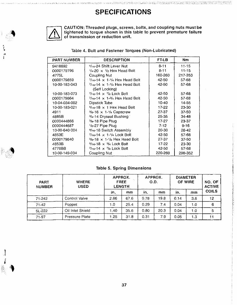
CAUTION: Threaded plugs, screws, bolts, and coupling nuts must be tightened to torque shown in this table to prevent premature failure of transmission or reduction unit.
Table 4. Bolt and Fastener Torques (Non-Lubricated)
PART NUMBER DESCRIPTION FT-LB Nm
9418892 5/'6-24 Shift Lever Nut 8-11 11-15 0000179796 '/4-20 x '/2 Hex Head Bolt 8-11 11-15 4775L Coupling Nut 160-260 217-353 0000179859 7116-14 x 1-'/4 Hex Head Bolt 42-50 57-68 1 0-00-183-043 7116-14 x 1-'/4 Hex Head Bolt 42-50 57-68
(Self Locking) 10-00-183-073 711 6-14 x 7/. Lock Bolt 42-50 57-68 0000179864 7/'6-14 x 1.3/4 Hex Head Bolt 42-50 57-68 1 0-04-034-002 Dipstick Tube 10-40 14-55 10-00-183-021 511 6-18 x 1 Hex Head Bolt 17-22 23-30 4911 3/.-16 x 1-'/4 Capscrew 27-37 37-50 4885B 3/4.14 Dryseal Bushing· 25-35 34-48 0000444866 3/.-18 Pipe Plug 17-27 23-37 0000444687 '/.-27 Pipe Plug 7-12 9-16 1 0-00-640-004 9/ j 6-18 Switch Assembly 20-30 28-42 4853E 7116-14 x 1-'/4 Lock Bolt 42-50 57-68 0000179840 3/.-18 x 1-'/. Hex Head Bolt 27-37 37-50 4853B 5/'6-18 x 3/4 Lock Bolt 17-22 23-30 4776BB 7116-14 x 7/. Lock Bolt 42-50 57-68 1 0-00-149-034 Coupling Nut 220-260 298-352
Table 5. Spring Dimensions
APPROX. APPROX. DIAMETER WHERE FREE 0.0. OF WIRE
NUMBER USED LENGTH
in. mm in. mm in. mm
71-242 Control Valve 2.66 67.6 0.78 19.8 0.14 3.6
71-42 Poppet 1.0 25.4 0.29 7.4 0.04 1.0
5L·222 Oil Inlet Shield 1.40 35.6 0.80 20.3 0.04 1.0
71-97 Pressure Plate 1.25 31.8 0.31 7.9 0.05 1.3
37
NO. OF ACTIVE COILS
12
6
5
11
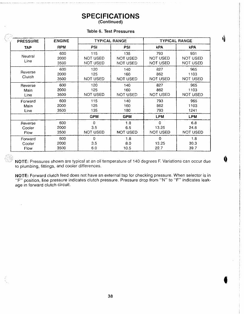
SPECI FICATIONS (Continued)
Table 6. Test Pressures
PRESSURE ENGINE TYPICAL RANGE TYPICAL RANGE
TAP RPM PSI PSI kPA kPA
Neutral 600 115 135 793 931
2000 NOT USED NOT USED NOT USED NOT USED line 3500 NOT USED NOT USED NOT USED NOT USED
Reverse 600 120 140 827 965
2000 125 160 862 1103 Clutch 3500 NOT USED NOT USED NOT USED NOT USED
Reverse 600 120 140 827 965 Main 2000 125 160 862 1103 line 3500 NOT USED NOT USED NOT USED NOT USED
Forward 600 115 140 793 965 Main 2000 125 160 862 1103 line 3500 135 180 793 1241
GPM GPM LPM LPM
Reverse 600 0 1.8 0 6.8 Cooler 2000 3.5 6.5 13.25 24.6 Flow 3500 NOT USED NOT USED NOT USED NOT USED
Forward 600 0 1,8 0 1.8 Cooler 2000 3.5 8.0 13.25 30.3 Flow 3500 6.0 10.5 22.7 39.7
NOTE: Pressures shown are typical at an oil temperature of 140 degrees F. Variations can occur due to plumbing, fiHings, and cooler differences.
NOTE: Forward clutch feed does not have an external tap for checking pressure. When selector is in "F" position, line pressure indicates clutch pressure. Pressure drop from "N" to "F" indicates leakage in forward clutch circuit.
38
•
1.523:1 REDUCTION UNITS
A. DESCRIPTION
The 1.523:1 reduction unit is mounted on the back of a 71 C or 72C transmission. The reduction unit output shaft rotates the same direction of the input shaft on the transmission. The output shaft rotates about one turn for everyone and one half turns of the input shaft. Lubricating oil is supplied to the reduction unit through ports on the back of the transmission.
NOTE: For inspection, maintenance, and troubleshooting refer to the Table of Contents at the front of this manual.
B. OVERHAUL
The general overhaul information described on page 12 applies to these reduction units. Before starting disassembly, review the exploded-view shown in Figure 10. The reduction unit can be disassembled following the index numbers shown in Figure 10. The following procedures are correct for most reduction units. Minor differences may be found.
39
CAUTION: Threaded plugs, screws, bolts, and coupling nut must be tightened to torque shown in Table 4 to prevent premature reduction unit failure.
• A new coupling nut must be used at assembly.
• Do not disassemble the pinion carrier assembly unless damaged. The necessary tools must be available for proper assembly. Use the exploded view, Figure 10, for disassembly and assembly.
• The bearing cup and cone are a matched set. If one is damaged both must be replaced.
• A solid spacer is used to control rolling torque (end play). Rolling torque must be checked after assembly of the reduction unit, before assembly to the transmission.
NOTE: Early reduction units used a collapsible spacer. If this spacer must be replaced use the solid spacer.
NOTE: Early reduction units used a bearing retainer on the output shaft end of reduction housing. To order correct parts refer to exploded-view, Figure 11.
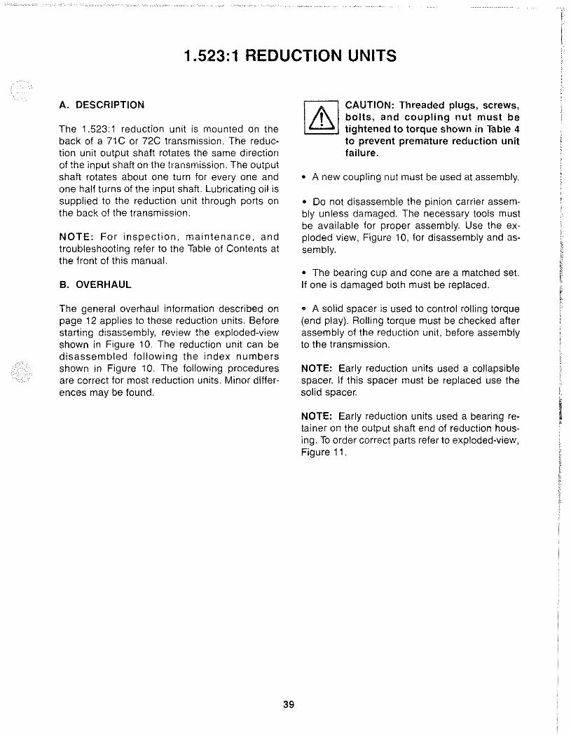
STEP 1. If removed, press bearing cone (23) on main shaft (21).
STEP 2. If removed, press bearing cups (24 and 29) into reduction housing (30).
STEP 3. Install main shaft (21) in reduction housing (30).
CAUTION: If original spacer is not used the reJ::lacement spacer should be the same length. Using an incorrect size spacer can result in premature failure of reduction unit.
Support main shaft (21). Install original spacer (25) and bearing cone (28) in reduction housing (30).
40
MAIN ~---SHAFT
!..-__ BEARING CONE
12824A
Bearing Cone Assembly ,
REDUCTION HOUSING
BEARING CUP
(~ 12789A
Bearing Cup Assembly
MAIN SHAFT
REDUCTION HOUSING
~. BEARING ~ CONE
SOLID lfr~~rrr- SPACER
12790A
Spacer and Bearing Cone Assembly
)
»
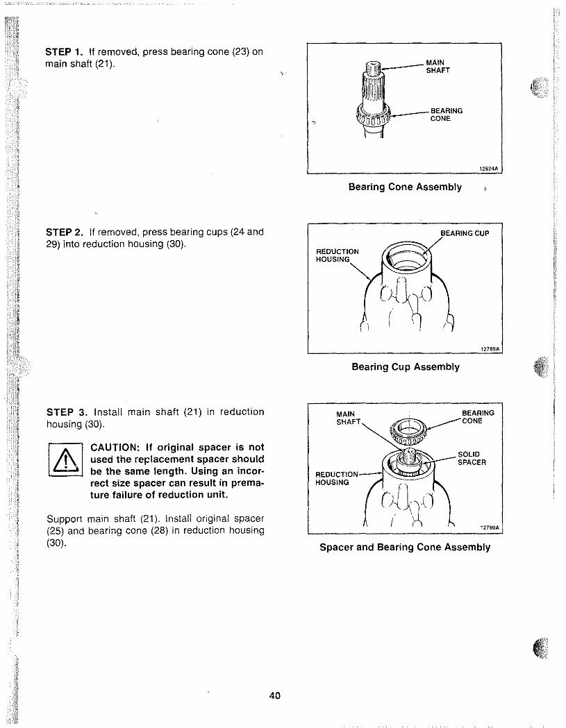
STEP 4. Place reduction housing (30) in press with main shaft (21) supported. Press bearing cone (28) on main shaft (21). Remove reduction, housing (30) from press.
STEP 5. Install oil seal (26) in reduction housing (30). Outer surface of oil seal (26) should be flush with face of reduction housing (30).
STEP 6. Slide coupling (6) on main shaft (21). Thread nut (5) on main shaft (21). Tighten nut (5) to torque shown in Table 4.
Attach a torque wrench to nut (5). Turn torque wrench to check rolling torque of bearings (11 and 16). Rolling torque should be 5 to 30 in-Ibs.
If rolling torque is over 30 in-Ibs replace spacer (25) with a longer one. If rolling torque is under 5 in-Ibs replace spacer (25) with a shorter one.
NOTE: Selection of the proper spacer (25) will result in 0 to 0.005 inch end play.
41
REDUCTION HOUSING
PRESS BEARING CONE
12791A
Bearing Cone Assembly
REDUCTION HOUSING
REDUCTION HOUSING
MAIN SHAFT
t\
Oil Seal Assembly
Coupling Assembly
12792A i
COUPLING NUT
12793A
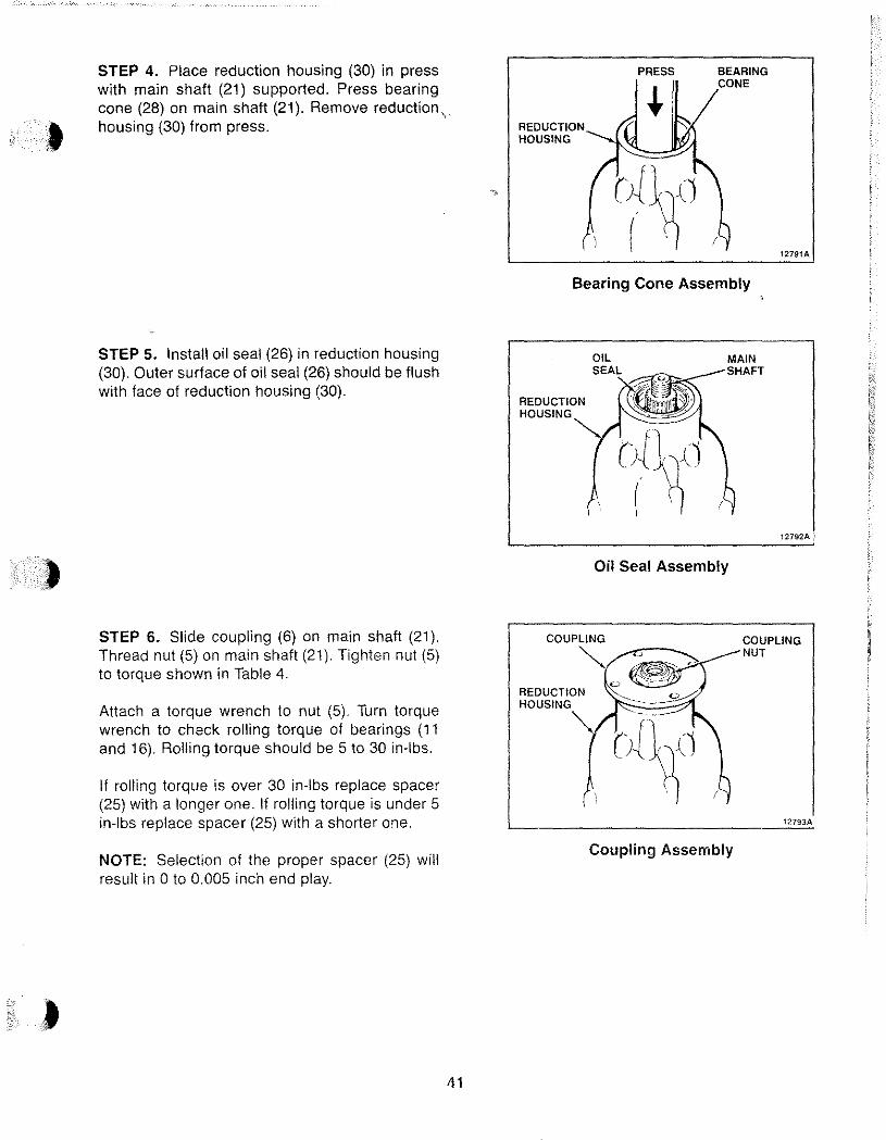
STEP 7. Slide sun gear (20) into sun gear hub (21). Turn sun gear hub (21) over. Install snap ring (19) in groove of sun gear (20).
STEP 8. Install sun gear (20) and sun gear hub (21) in reduction housing (30).
Thread four bolts (17) into reduction housing. Tighten bolts (17) to torque shown in Table 4.
STEP 9. Install pinion carrier (8) in reduction housing (30). Install snap ring (7) in groove of main shaft (21).
42
SNAP RING_L';~
SUN GEAR HUB
GEAR
Sun Gear Assembly
SUN
Sun Gear Installation
PINION CARRIER
REDUCTION HOUSING
Pinion Carrier Instaliation
12786A :
12825A
SNAP RING
12S26A
)
, ,
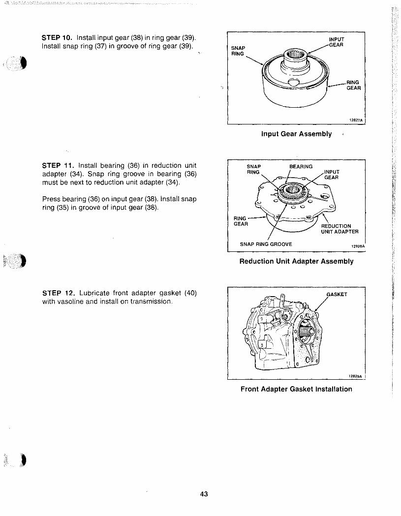
STEP 10. Install input gear (38) in ring gear (39). Install snap ring (37) in groove of ring gear (39).
STEP 11. Install bearing (36) in reduction unit adapter (34). Snap ring groove in bearing (36) must be next to reduction unit adapter (34).
Press bearing (36) on input gear (38). Install snap ring (35) in groove of input gear (38).
STEP 12. Lubricate front adapter gasket (40) with vasoline and install on transmission.
43
SNAP RING
INPUT GEAR
, __ RING
GEAR
12827A
Input Gear Assembly
SNAP RING
GEAR
RING ----1\i;~=:::::o::'!:fJ GEAR REflLlC:TI(l,N I
UNIT ADAPTER
SNAP RING GROOVE 12828A
Reduction Unit Adapter Assembly
GASKET
t2829A i
Front Adapter Gasket Installation
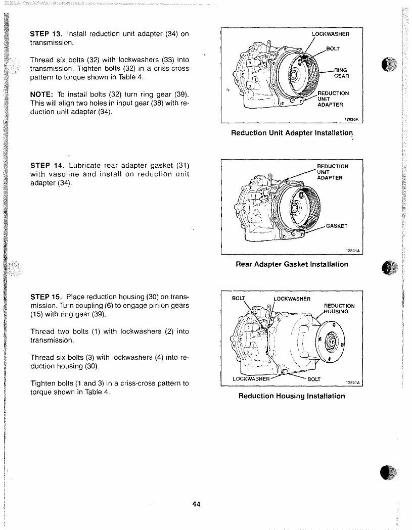
STEP 13. Install reduction unit adapter (34) on transmission.
Thread six bolts (32) with lockwashers (33) into transmission. Tighten bolts (32) in a criss-cross pattern to torque shown in Table 4.
NOTE: To install bolts (32) turn ring gear (39). This will align two holes in input gear (38) with reduction unit adapter (34).
STEP 14. Lubricate rear adapter gasket (31) with vasoline and install on reduction unit adapter (34).
STEP 15. Place reduction housing (30) on transmission. Turn coupling (6) to engage pinion gears (15) with ring gear (39).
Thread two bolts (1) with lockwashers (2) into transmission.
Thread six bolts (3) with lockwashers (4) into reduction housing (30).
Tighten bolts (1 and 3) in a criss-cross pattern to torque shown in Table 4.
44
LOCKWASHER
12830A
Reduction Unit Adapter Installation !
REDUCTION UNIT ADAPTER
GASKET
12831A
•
Rear Adapter Gasket Installation tJ BOLT LOCKWASHER
LOCKWASHER BOLT 12801A
Reduction Housing Installation
5
21
17
,~ J
»
34
!2S!66
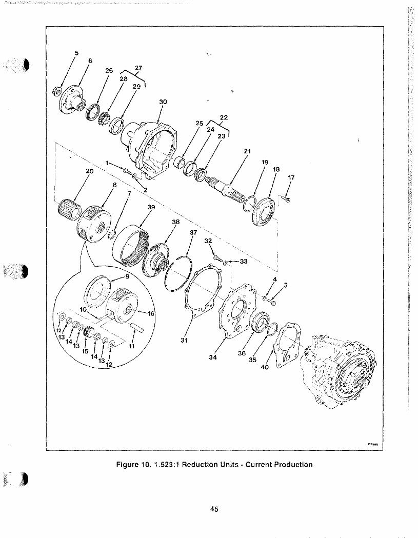
Figure 10. 1.523:1 Reduction Units - Current Production
45
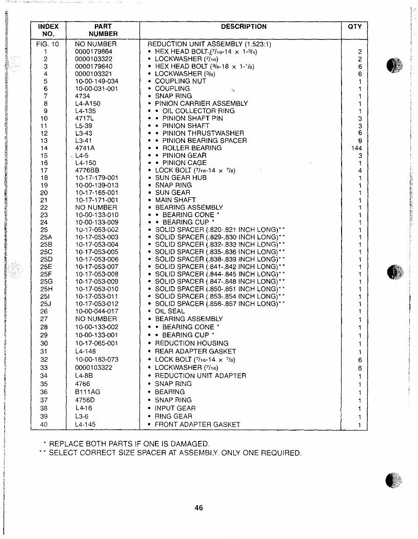
INDEX PART DESCRIPTION QTY NO. NUMBER
FIG. 10 NO NUMBER REDUCTION UNIT ASSEMBLY (1.523:1) 1 0000179864 • HEX HEAD BOLT .,(7/16-14 X P/4) 2 2 0000103322 • LOCKWASHER (7/16) 2 • 3 0000179840 • HEX HEAD BOLT (3/8-18 X 1-'/8) 6 4 0000103321 • LOCKWASHER (3/8) 6 5 1 0-00-149-034 • COUPLING NUT 1 6 10-00-031-001 • COUPLING "? 1 7 4734 • SNAP RING 1 8 L4-A 150 • PINION CARRIER ASSEMBLY 1 9 L4-135 • • OIL COLLECTOR RING 1
10 4717L • • PINION SHAFT PIN 3 11 L5-39 • • PINION SHAFT 3 12 L3-43 • • PINION THRUSTWASHER 6 13 L3-41 • • PINION BEARING SPACER 9 14 4741 A • • ROLLER BEARING 144 15 - L4-5 • • PINION GEAR 3 16 L4-150 • • PINION CAGE 1 17 4776BB • LOCK BOLT (7h6-14 X 7/8) 4 18 10-17-179-001 • SUN GEAR HUB 1 19 10-00-139-013 • SNAP RING 1 20 10-17-165-001 • SUN GEAR 1 21 10-17-171-001 • MAIN SHAFT 1 22 NO NUMBER • BEARING ASSEMBLY 1 23 1 0-00-133-01 0 • • BEARING CONE' 1 24 1 0-00-133-009 • • BEARING CUP' 1 25 10-i 7-053-002 • SOLID SPACER (.820~.821 !NCH LONG)* * 1 25A 1 0-1 7-053-003 • SOLID SPACER (.829-.830 INCH LONG),' 1 25B 1 0-17-053-004 • SOLID SPACER (.832-.833 INCH LONG),' 1 25C 1 0-17-053-005 • SOLID SPACER (.835-.836 INCH LONG),' 1 250 1 0-17-053-006 • SOLID SPACER (.838-.839 INCH LONG),' 1 25E 10-17-053-007 • SOLID SPACER (.841-.842 INCH LONG)" 1 • 25F 1 0-17-053-008 • SOLID SPACER (.844-.845 INCH LONG)" 1 25G 1 0-17-053-009 • SOLID SPACER (.847-.848 INCH LONG)" 1 25H 10-17-053-010 • SOLID SPACER (.850-.851 INCH LONG),' 1 251 10-17-053-011 • SOLID SPACER (.853-.854 INCH LONG)" 1 25J 10-17-053-012 • SOLID SPACER (.856-.857 INCH LONG),' 1 26 1 0-00-044-017 • OIL SEAL 1 27 NO NUMBER • BEARING ASSEMBLY 1 28 1 0-00-133-002 • • BEARING CONE' 1 29 1 0-00-133·001 • • BEARING CUP' 1 30 10-17-065-001 • REDUCTION HOUSING 1 31 L4-146 • REAR ADAPTER GASKET 1 32 10-00-183-073 • LOCK BOLT (7h6-14 X 7/8) 6 33 0000103322 • LOCKWASHER (7h6) 6 34 L4-8B • REDUCTION UNIT ADAPTER 1 35 4766 • SNAP RING 1 36 B111AG • BEARING 1 37 47560 • SNAP RING 1 38 L4·16 • INPUT GEAR 1 39 L3-6 • RING GEAR 1 40 L4-145 • FRONT ADAPTER GASKET 1
, REPLACE BOTH PARTS IF ONE IS DAMAGED . • , SELECT CORRECT SIZE SPACER AT ASSEMBLY ONLY ONE REQUIRED.
• 3:';:/
46
)
/i. 4
IlSI1A
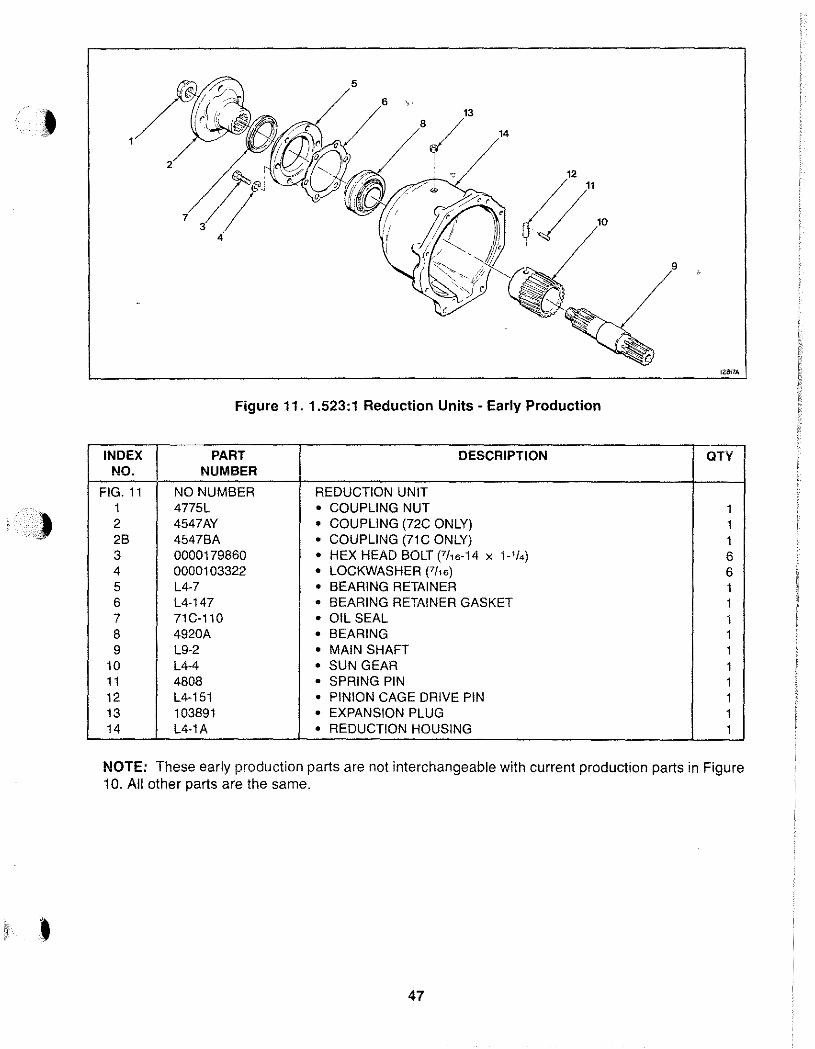
Figure 11. 1.523:1 Reduction Units - Early Production
INDEX PART DESCRIPTION aTr NO. NUMBER
FIG. 11 NO NUMBER REDUCTION UNIT 1 4775L • COUPLING NUT 1 2 4547AY • COUPLING (72C ONLY) 1 2B 4547BA • COUPLING (71C ONLY) 1 3 0000179860 • HEX HEAD BOLT (7/16-14 x 1-'t.) 6 4 0000103322 • LOCKWASHER (7/16) 6 5 L4-7 • BEARING RETAINER 1 6 L4-147 • BEARING RETAINER GASKET 1 7 71C-110 • OIL SEAL 1 8 4920A • BEARING 1 9 L9-2 • MAIN SHAFT 1
10 L4-4 • SUN GEAR 1 11 4808 • SPRING PIN 1 12 L4-151 • PINION CAGE DRIVE PIN 1 13 103891 • EXPANSION PLUG 1 14 L4-1A • REDUCTION HOUSING 1
NOTE: These early production parts are not interchangeable with current production parts in Figure 10. All other parts are the same.
47
1.88:1 AND 1.91:1 REDUCTION UNITS
A. DESCRIPTION
The 1.88: 1 and 1.91: 1 reduction units are mounted on the back of a 71 C or 72C transmission. The reduction unit output shaft rotates the opposite direction of the input shaft on the transmission. The output shaft rotates about one turn for every two turns of the input shaft. Lubricating oil is supplied to the reduction unit through ports on the back of the transmission.
NOTE: For inspection, maintenance, and troubleshooting refer to the Table of Contents at the front of this manual.
B. OVERHAUL
The general overhaul information described on page 12 applies to these reduction units. Before starting disassembly, review the exploded-view shown in Figure 12. The reduction unit can be disassembled following the index numbers in Figure 12. The following procedures are correct for most reduction units. Minor differences may be found.
NOTE: Current Production 1.91: 1 reduction units use a reduction unit adapter (39), lock plates (23), pinion carrier gasket (33), and o-ring (35) for noise reduction.
48
CAUTION: Threaded plugs, screws, bolts, and coupling nut must be tightened to torque shown in Table 4 to prevent premature reduction unit failure.
• A new coupling nut must be used at assembly.
• Do not disassemble the pinion carrier assembly unless damaged. The necessary tools must be available for proper assembly. Use exploded view, Figure 12, for disassembly and assembly.
• The bearing cup and cone are a matched set. If one is damaged both must be replaced.
• A solid spacer is used to control rolling torque (end play). Rolling torque must be checked after assembly of the reduction unit, before assembly to the transmission.
NOTE: Early 1.91: 1 reduction units used a collapsible spacer. If this spacer must be replaced use the solid spacer.
NOTE: Early 1.91:1 reduction units used a bearing retainer on the output shaft end of reduction housing. To order correct parts refer to explodedview, Figure 13.
•
•
•
)
I
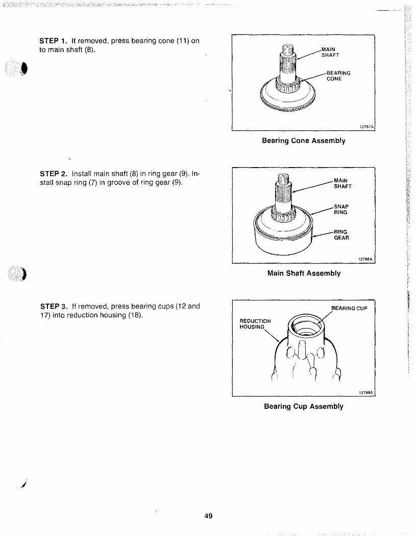
STEP 1. If removed, press bearing cone (11) on to main shaft (8) .
STEP 2. Install main shaft (8) in ring gear (9). Install snap ring (7) in groove of ring gear (9).
STEP 3. If removed, press bearing cups (12 and 17) into reduction housing (18).
49
Bearing Cone Assembly
MAIN SHAFT
RING
GEAR
Main Shaft Assembly
12787A
BEARING CUP
REDUCTION HOUSING
Bearing Cup Assembly
12789A
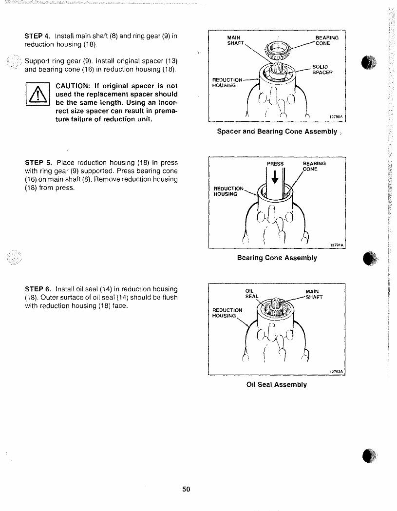
STEP 4. Install main shaft (8) and ring gear (9) in reduction housing (18).
Support ring gear (9). Install original spacer (13) and bearing cone (16) in reduction housing (18).
CAUTION: If original spacer is not used the replacement spacer should be the same length. Using an incorrect size spacer can result in prema-ture failure of reduction unit.
STEP 5. Place reduction housing (18) in press with ring gear (9) supported. Press bearing cone (16) on main shaft (8). Remove reduction housing (18) from press.
STEP 6. Install oil seal (14) in reduction housing (18). Outer surface of oil seal (14) should be flush with reduction housing (18) face.
50
MAIN SHAFT
SOLID SPACER
12790A
Spacer and Bearing Cone Assembly
REDUCTION HOUSING
PRESS BEARING CONE
(~ Bearing Cone Assembly
REDUCTION HOUSING
MAIN SHAFT
Oil Seal Assembly
12792A
•
•
»
)
STEP 7. Slide coupling (6) on main shaft (8). Thread nut (5) on main shaft (8). Tighten nut (5) to torque shown in Table 4.
Attach a torque wrench to nut (5). Turn torque wrench to check rolling torque of bearings (11 and 16). Rolling torque should be 5 to 30 in-Ibs.
If rolling torque is over 30 in-Ibs replace spacer (13) with a longer one. If rolling torque is under 5 in-Ibs replace spacer (13) with a shorter one.
NOTE: Selection of the proper spacer (13) will result in 0 to 0.005 inch end play.
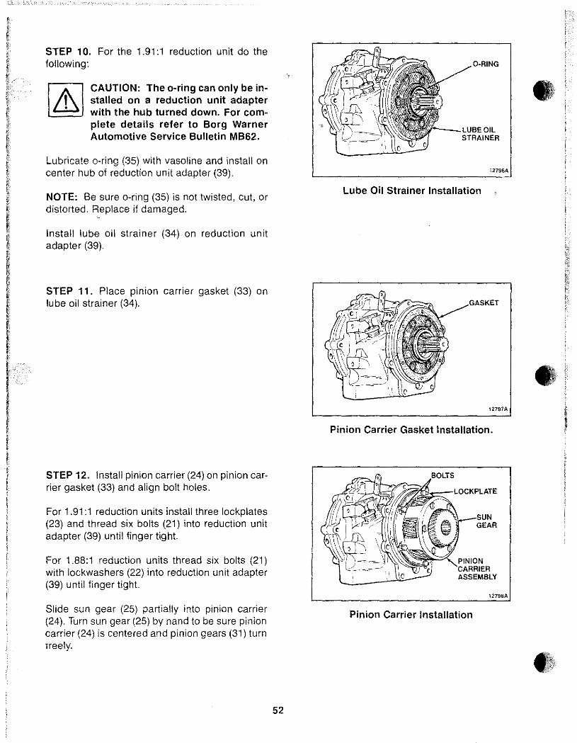
STEP 8. If removed, install bearing (41) and snap ring (40) in transmission.
Lubricate front adapter gasket (42) with vasoline and install on transmission.
STEP 9. Install reduction unit adapter (39) on transmission.
Thread six bolts (37) with lockwashers (38) into transmission. Tighten bolts (37) in a criss-cross pattern to torque shown in Table 4.
51
COUPLING
REDUCTION HOUSING
~ .'"
COUPLING NUT
12793A
Coupling Assembly
SNAP RING
BEARING
12794A I
Front Adapter Gasket Installation
~rJ~1l::?i"'];;;:;;~LOCKWASHERS
UNIT ADAPTER
1279SA
Reduction Unit Adapter Installation
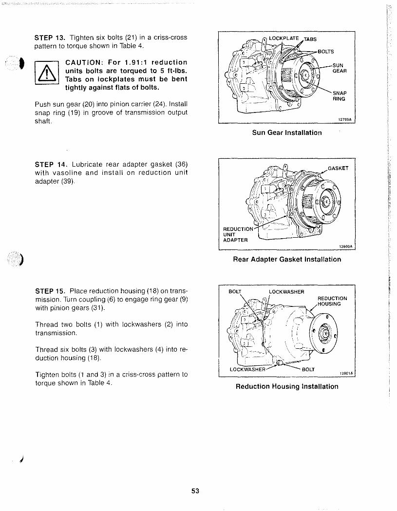
STEP 10. For the 1.91:1 reduction unit do the following:
CAUTION: The o-ring can only be installed on a reduction unit adapter with the hub turned down. For complete details refer to Borg Warner Automotive Service Bulletin MB62.
Lubricate o-ring (35) with vasoline and install on center hub of reduction unit adapter (39).
NOTE: Be sure o-ring (35) is not twisted, cut, or distorted. ~eplace if damaged.
Install lube oil strainer (34) on reduction unit adapter (39).
STEP 11. Place pinion carrier gasket (33) on lube oil strainer (34).
STEP 12. Install pinion carrier (24) on pinion carrier gasket (33) and align bolt holes.
For 1.91:1 reduction units install three lockplates (23) and thread six bolts (21) into reduction unit adapter (39) until finger tight.
For 1.88: 1 reduction units thread six bolts (21) with lockwashers (22) into reduction unit adapter (39) until finger tight.
Slide sun gear (25) partially into pinion carrier (24), Turn sun gear (25) by hand to be sure pinion carrier (24) is centered and pinion gears (31) turn freely.
52
O-RING
r--_LUBEOIL STRAINER
12796A
Lube Oil Strainer Installation
12797A
Pinion Carrier Gasket Installation.
GEAR
ASSEMBLY
12798A
Pinion Carrier Installation
•
•
•
)
STEP 13. Tighten six bolts (21) in a criss-cross pattern to torque shown in Table 4 .
[2@ CAUTION: For 1.91:1 reduction
t,\ units bolts are torqued to 5 ft-Ibs. ~ Tabs on lockplates must be bent
tightly against flats of bolts.
Push sun gear (20) into pinion carrier (24). Install snap ring (19) in groove of transmission output shaft.
STEP 14. Lubricate rear adapter gasket (36) with vasoline and install on reduction unit adapter (39).
STEP 15. Place reduction housing (18) on transmission. Turn coupling (6) to engage ring gear (9) with pinion gears (31).
Thread two bolts (1) with lockwashers (2) into transmission.
Thread six bolts (3) with lockwashers (4) into reduction housing (18).
Tighten bolts (1 and 3) in a criss-cross pattern to torque shown in Table 4.
53
"L>--_SUN GEAR
SNAP RING
12799A
Sun Gear Installation
UNIT ADAPTER
12800A
Rear Adapter Gasket Installation
BOLT LOCKWASHER
LOCKWASHER BOLT
REDUCTION HOUSING
12801A
Reduction Housing Installation
• , !
I , ~
20
• 42
128028
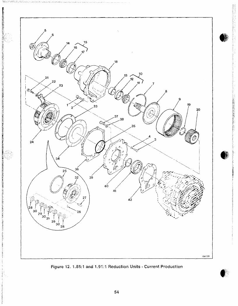
Figure 12.1.88:1 and 1.91:1 Reduction Units· Current Production • 54
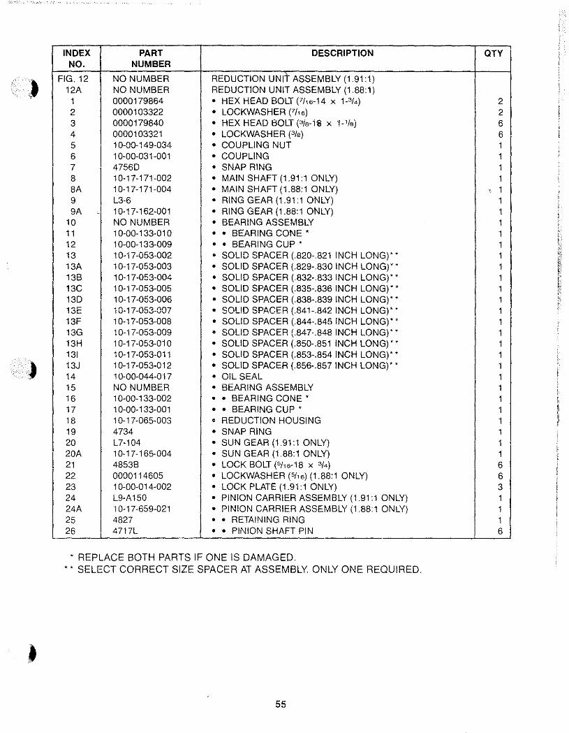
INDEX PART DESCRIPTION aTY NO. NUMBER
FIG. 12 NO NUMBER REDUCTION UNit ASSEMBLY (1.91:1) 12A NO NUMBER REDUCTION UNIT ASSEMBLY (1.88:1)
1 0000179864 • HEX HEAD BOLT (711 6-14 X P/4) 2 2 0000103322 • LOCKWASHER (7/16) 2 3 0000179840 • HEX HEAD BOLT (3is-l11 X 1-'/s) 6 4 0000103321 • LOCKWASHER (3fs) 6 5 10-00-149-034 • COUPLING NUT 1 6 10-00-031-001 • COUPLING 1 7 4756D • SNAP RING 1 8 10-17-171-002 • MAIN SHAFT (1.91:1 ONLY) 1 8A 10-17-171-004 • MAIN SHAFT (1.88:1 ONLY) . 1 9 L3-6 • RING GEAR (1.91:1 ONLY) 1 9A - 10-17-162-001 • RING GEAR (1.88:1 ONLY) 1
10 NO NUMBER • BEARING ASSEMBLY 1 11 1 0-00-133-01 0 • • BEARING CONE' 1 12 10-00-133-009 • • BEARING CUP' 1 13 10-17-053-002 • SOLID SPACER (.820-.821 INCH LONG)" 1 13A 10-17-053-003 • SOLID SPACER (.829-.830 INCH LONG)" 1 13B 10-17-053-004 • SOLID SPACER (.832-.833 INCH LONG)" 1 13C 1 0-1 7-053-005 • SOLID SPACER (.835-.836 INCH LONG)" 1 13D 1 0-17-053-006 • SOLID SPACER (.838-.839 INCH LONG)" 1 13E 1 O~ 17-053-007 • SOLID SPACER (.841-.842 INCH LONG)" 1 13F 1 0-1 7-053-008 • SOLID SPACER (.844-.845 INCH LONG),' 1 13G 10-17-053-009 • SOLID SPACER (.847·.848 INCH LONG),' 1 13H 10-17-053-010 • SOLID SPACER (.850-.851 INCH LONG)" 1 131 1 0-17-053-011 • SOLID SPACER (.853-.854 INCH LONG)" 1 13J 10-17-053-012 • SOLID SPACER (.856-.857 INCH LONG),' 1 14 1 0-00-044-017 • OIL SEAL 1 15 NO NUMBER • BEARING ASSEMBLY 1 16 1 0-00-1 33-002 • • BEARING CONE' 1 17 1 0-00-133-001 • • BEARING CUP' 1 18 10-17-065-003 • REDUCTION HOUSING 1 19 4734 • SNAP RING 1 20 L7-104 • SUN GEAR (1.91:1 ONLY) 1 20A 10-17-165-004 • SUN GEAR (1.88:1 ONLY) 1 21 4853B • LOCK BOLT (5/16-18 X 3/4) 6 22 0000114605 • LOCKWASHER (511 6) (1.88:1 ONLY) 6 23 10-00-014-002 • LOCK PLATE (1.91:1 ONLY) 3 24 L9-A150 • PINION CARRIER ASSEMBLY (1.91:1 ONLY) 1 24A 10-17-659-021 • PINION CARRIER ASSEMBLY (1.88:1 ONLY) 1 25 4827 • • RETAINING RING 1 26 4717L • • PINION SHAFT PIN 6
• REPLACE BOTH PARTS IF ONE IS DAMAGED . •• SELECT CORRECT SIZE SPACER AT ASSEMBLY ONLY ONE REQUIRED.
55
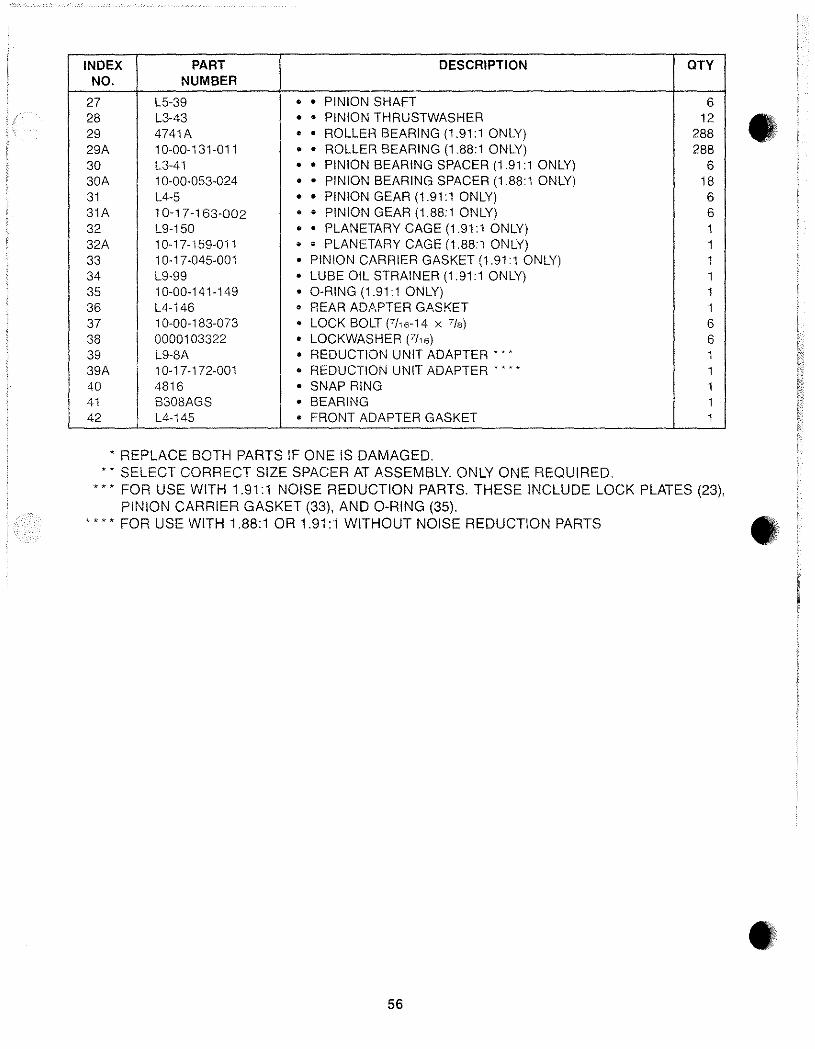
INDEX PART DESCRIPTION aTY NO. NUMBER
27 L5-39 • • PINION SHAFT 6 28 L3-43 • • PINION THRUSTWASHER 12 29 4741A • • ROLLER BEARING (1.91:1 ONLY) 288 29A 10-00-131-011 • • ROLLER BEARING (1.88:1 ONLY) 288 30 L3-41 • • PINION BEARING SPACER (1.91:1 ONLY) 6 30A 10-00-053-024 • • PINION BEARING SPACER (1.88:1 ONLY) 18 31 L4-5 • • PINION GEAR (1.91:1 ONLY) 6 31A 10-17-163-002 • • PINION GEAR (1.88:1 ONLY) 6 32 L9-150 • • PLANETARY CAGE (1.91:1 ONLY) 1 32A 10-17-159-011 • • PLANETARY CAGE (1.88:1 ONLY) 1 33 10-17-045-001 • PINION CARRIER GASKET (1.91:1 ONLY) 1 34 L9-99 • LUBE OIL STRAINER (1.91:1 ONLY) 1 35 10-00-141-149 • O-RING (1.91:1 ONLY) 1 36 L4-146 • REAR ADAPTER GASKET 1 37 10-00-183-073 • LOCK BOLT (7/,6-14 X 7/8) 6 38 0000103322 • LOCKWASHER (7/16) 6 39 L9-8A • REDUCTION UNIT ADAPTER'" 1 39A ; 10-17-172-001 • REDUCTION UNIT ADAPTER···· 1 40 4816 • SNAP RING 1 41 B308AGS • BEARING 1 42 L4-145 • FRONT ADAPTER GASKET 1
• REPLACE BOTH PARTS IF ONE IS DAMAGED. " SELECT CORRECT SIZE SPACER AT ASSEMBLY. ONLY ONE REQUIRED.
, * * FOR USE WITH 1.91:1 NOISE REDUCTION PARTS. THESE INCLUDE LOCK PLATES (23), PINION CARRIER GASKET (33), AND O·RING (35).
"" FOR USE WITH 1.88:1 OR 1.91:1 WITHOUT NOISE REDUCTION PARTS
56
•
•
•
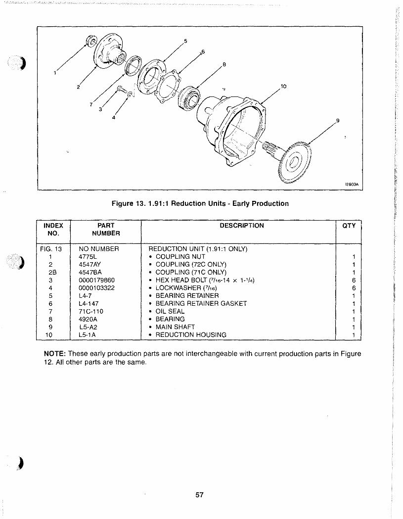
)
9
!2S03A
Figure 13. 1.91: 1 Reduction Units· Early Production
INDEX PART DESCRIPTION QTY NO. NUMBER
FIG. 13 NO NUMBER REDUCTION UNIT (1.91:1 ONLY) 1 4775L • COUPLING NUT 1 2 4547AY • COUPLING (72C ONLY) 1 2B 4547BA • COUPLING (71C ONLY) 1 3 0000179860 • HEX HEAD BOLT F/,6-14 x 1-'/4) 6 4 0000103322 • LOCKWASHER (7h6) 6 5 L4-7 • BEARING RETAINER 1 6 L4-147 • BEARING RETAINER GASKET 1 7 71 C-110 • OIL SEAL 1 8 4920A • BEARING 1 9 L5-A2 • MAIN SHAFT 1
10 L5-1A • REDUCTION HOUSING 1
NOTE: These early production parts are not interchangeable with current production parts in Figure 12. All other parts are the same.
57
2.57:1 AND 2.91:1 REDUCTION UNITS
A. DESCRIPTION
The 2.57:1 and 2.91:1 reduction units are mounted on the back of a 71 C or 72C transmission. The reduction unit output shaft rotates the same direction as the input shaft on the transmission. The output shaft rotates about one turn for every two and one half to three turns of the input shaft. Lubricating oil is supplied to the reduction unit through ports on the back of the transmission.
NOTE: For inspection, maintenance, and troubleshooting refer to the Table of Contents at the front of this manual.
B. OVERHAUL
The general overhaul information described on page 12 applies to these reduction units. Before starting disassembly, review the exploded-view shown in Figure 14. The reduction unit can be disassembled following the index numbers in Figure 14. The following procedures are correct for most reduction units. Minor differences may be found.
58
CAUTION: Threaded plugs, screws, bolts, and coupling nut must be tightened to torque shown in Table 4 to prevent premature reduction unit failure.
• A new coupling nut must be used at assembly.
• Do not disassemble the pinion cage and output shaft assembly unless damaged. The necessary tools must be available for proper assembly. Use exploded view, Figure 14, for disassembly and assembly.
• The bearing cup and cone are a matched set. If one is damaged both must be replaced.
• A solid spacer is used to control rolling 10rque (end play). Rolling torque must be checked after assembly of the reduction unit, before assembly to the transmission.
NOTE: Early reduction units used a collapsible spacer. If this spacer must be replaced use the solid spacer.
NOTE: Early reduction units used a bearing retainer on the output shaft end of the reduction housing. To order correct parts refer to explodedview, Figure 15.
••
•
•
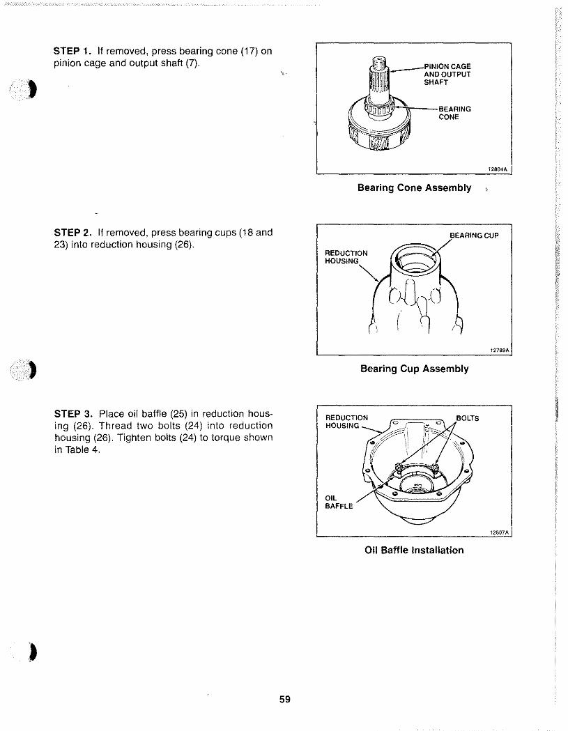
,
)
)
STEP 1. If removed, press bearing cone (17) on pinion cage and output shaft (7).
STEP 2. If removed, press bearing cups (18 and 23) into reduction housing (26).
STEP 3. Place oil baffle (25) in reduction hous· ing (26). Thread two bolts (24) into reduction housing (26). Tighten bolts (24) to torque shown in Table 4.
59
___ 'PIN!'O.N CAGE AND OUTPUT SHAFT
:lI'lr,--BEARING CONE
Bearing Cone Assembly
t2804A
BEARING CUP
REDUCTION HOUSING
OIL BAFFLE
Bearing Cup Assembly
Oil Baffle Installation
, 12807A I
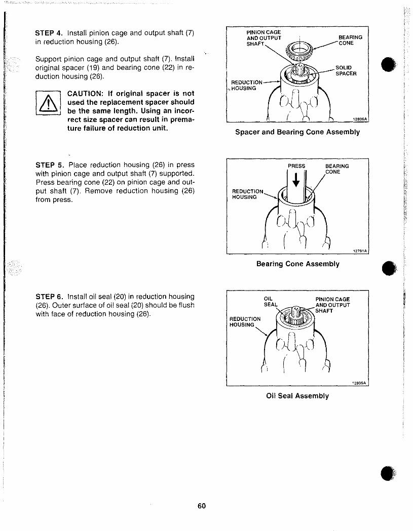
STEP 4. Install pinion cage and output shaft (7) in reduction housing (26).
Support pinion cage and output shaft (7). Install original spacer (19) and bearing cone (22) in reduction housing (26).
CAUTION: If original spacer is not used the replacement spacer should be the same length. Using an incorrect size spacer can result in prema-ture failure of reduction unit.
STEP 5. Place reduction housing (26) in press with pinion cage and output shaft (7) supported. Press bearing cone (22) on pinion cage and output shaft (7). Remove reduction housing (26) from press.
STEP 6. Install oil seal (20) in reduction housing (26). Outer surface of oil seal (20) should be flush with face of reduction housing (26).
60
PINION CAGE AND OUTPUT SHAFT
REDUCTION HOUSING
: BEARING
~CONE
SOLID SPACER
12806A
Spacer and Bearing Cone Assembly
REDUCTION HOUSING
PRESS BEARING CONE
Bearing Cone Assembly
REDUCTION HOUSING
Oil Seal Assembly
12791A
12805A
•
•
•
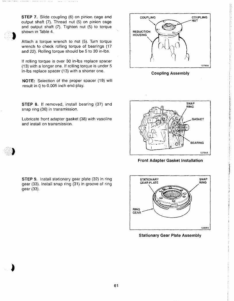
,
)
STEP 7. Slide coupling (6) on pinion cage and output shaft (7). Thread nut (5) on pinion cage and output shaft (7). Tighten nut (5) to torque shown in Table 4.
Attach a torque wrench to nut (5). Turn torque wrench to check rolling torque of bearings (17 and 22). Rolling torque should be 5 to 30 in-Ibs.
If rolling torque is over 30 in-Ibs replace spacer (13) with a longer one. If rolling torque is under 5 in-Ibs replace spacer (13) with a shorter one.
NOTE: Selection of the proper spacer (19) will result in Q to 0.005 inch end play.
STEP 8. If removed, install bearing (37) and snap ring (36) in transmission.
Lubricate front adapter gasket (38) with vasoline and install on transmission.
STEP 9. Install stationary gear plate (32) in ring gear (33). Install snap ring (31) in groove of ring gear (33).
61
COUPLING
REOUCTION HOUSING
Coupling Assembly
COUPLING NUT
12793A
BEARING
12794A
Front Adapter Gasket Installation
STATIONARY GEAR PLATE
RING GEAR
SNAP
1280aA
Stationary Gear Plate Assembly
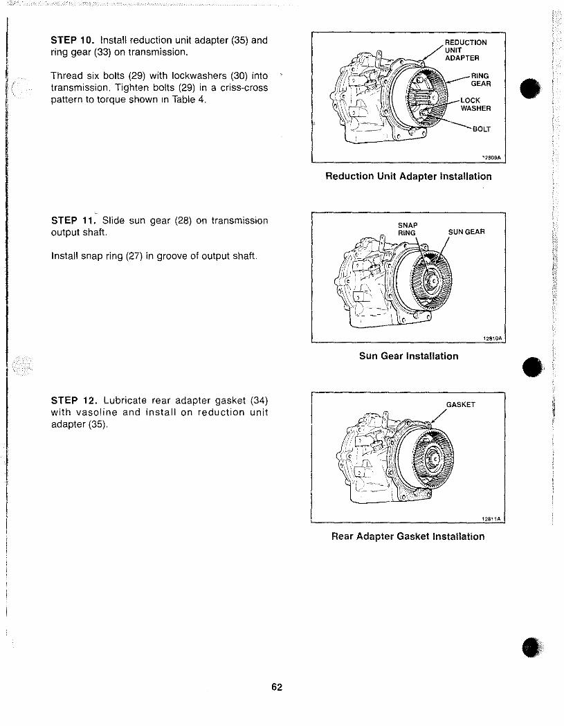
STEP 10. Install reduction unit adapter (35) and ring gear (33) on transmission.
Thread six bolts (29) with lockwashers (30) into transmission. Tighten bolts (29) in a criss·cross pattern to torque shown in Table 4.
STEP 11. Slide sun gear (28) on transmission output shaft.
Install snap ring (27) in groove of output shaft.
STEP 12. Lubricate rear adapter gasket (34) with vasoline and install on reduction unit adapter (35).
62
REDUCTION UNIT ADAPTER
RING GEAR
BOLT
12S09A
Reduction Unit Adapter Installation
SNAP RING SUN GEAR
12810A
Sun Gear Installation
12811A
Rear Adapter Gasket Installation
•
•
•
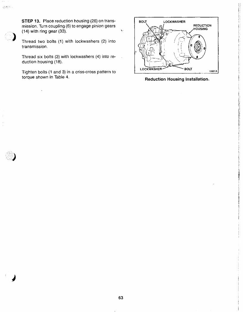
)
)
STEP 13. Place reduction housing (26) on transmission. Turn coupling (6) to engage pinion gears (14) with ring gear (33).
Thread two bolts (1) with lockwashers (2) into transmission.
Thread six bolts (3) with lockwashers (4) into reduction housing (18).
Tighten bolts (1 and 3) in a criss-cross pattern to torque shown in Table 4.
,
63
LOCKWASHER BOLT
REDUCTION HOUSING
12601A
Reduction Housing Installation,
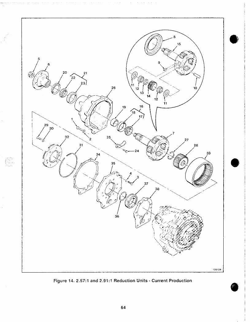
L_____ 291:1 Reduction Un. .
-
-------=~=:_::~:urr·ent Production 'ts Curren 257:1 and . Figure 14. .
64
•
•
128128
•
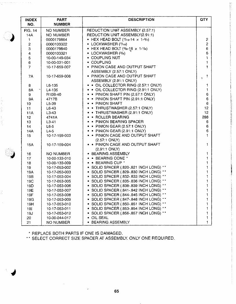
INDEX PART DESCRIPTION aTY NO. NUMBER
FIG. 14 NO NUMBER REDUCTION UNH ASSEMBLY (2.57:1) 14A NO NUMBER REDUCTION UNIT ASSEMBLY(2.91:1)
1 0000179864 • HEX HEAD BOLT (7/,6-14 X P/4) 2 2 0000103322 • LOCKWASHER (7/16) 2 3 0000179840 • HEX HEAD BOLT (3/a-18 X 1-'/a\ 6 '" ' 4 0000103321 • LOCKWASHER (3/a) 6 5 10-00-149-034 • COUPLING NUT 1 6 1 0-00-031-001 • COUPLING 1 7 10-17-659-007 • PINION CAGE AND OUTPUT SHAFT 1
ASSEMBLY (2.57:1 ONLY) 7A 10-17-659-008 • PINION CAGE AND OUTPUT SHAFT
ASSEMBLY (2.91:1 ONLY) %
1
8 L6-135 • • OIL COLLECTOR RING (2,57:1 ONLY) 1 8A c L4-135 • • OIL COLLECTOR RING (2.91:1 ONLY) 1 9 R10B-40 • • PINION SHAFT PIN (2.57:1 ONLY) 6 9A 4717B • • PINION SHAFT PIN (2.91:1 ONLY) 6
10 L5-39 • • PINION SHAFT 6 11 L6-43 • • THRUSTWASHER (2.57:1 ONLY) 12 11A L3-43 • • THRUSTWASHER (2.91:1 ONLY) 12 12 4741A • • ROLLER BEARING 288 13 L3-41 • • PINION BEARING SPACER 6 14 L6-5 • • PINION GEAR (2,57:1 ONLY) 6 14A L4-5 • • PINiON GEAR (2,91:1 ONLY) 6 15 10-17-159-003 • • PINION CAGE AND OUTPUT SHAFT 1
(2,57:1 ONLY) 15A 10-17-159-004 • • PINION CAGE AND OUTPUT SHAFT 1
(2.91:1 ONLY)
J 16 NO NUMBER • BEARING ASSEMBLY 1 17 10-00-.133-010 • • BEARING CONE' 1 18 1 0-00-1 33-009 • • BEARING CUP' 1 19 1 0-17-053-002 • SOLID SPACER (.820-.821 INCH LONG) •• 1 19A 1 0-17-053-003 • SOLID SPACER (,829-,830 INCH LONG) •• 1 19B 1 0-17-053-004 • SOLID SPACER (.832-.833 INCH LONG) •• 1 19C 1 0-17-053-005 • SOLID SPACER (,835-,836 INCH LONG) •• 1 190 1 0-17-053-006 • SOLID SPACER (.838-.839 INCH LONG) •• 1 19E 10-17-053-007 • SOLID SPACER (.841-.842 INCH LONG) .. 1 19F 1 0-1 7-053-008 • SOLID SPACER (.844-.845 INCH LONG) •• 1 19G 1 0-17-053-009 • SOLID SPACER (.847-.848 INCH LONG) •• 1 19H 10-17-053-010 • SOLID SPACER (.850-.851 INCH LONG) •• 1 19! 10-17-053-011 • SOLID SPACER (.853-.854 INCH LONG) •• 1 19J 10-17-053-012 • SOLID SPACER (.856-.857 INCH LONG) •• 1 20 10-00-044-017 • OIL SEAL 1 21 NO NUMBER • BEARING ASSEMBLY 1
• REPLACE BOTH PARTS IF ONE IS DAMAGED . •• SELECT CORRECT SIZE SPACER AT ASSEMBLY. ONLY ONE REQUIRED,
65
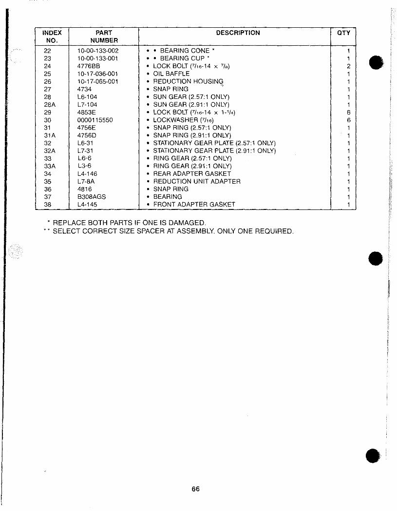
INDEX PART DESCRIPTION QTY NO. NUMBER
22 10-00-133-002 • • BEARING CONE' 1 23 1 0-00-133-001 • • BEARING CUP' 1 24 4776BB • LOCK BOLT (7/16-14 X 7/8) 2 • 25 10-17-036-001 • OIL BAFFLE 1 26 10-17-065-001 • REDUCTION HOUSING 1 27 4734 • SNAP RING
.~
1 28 L6-104 • SUN GEAR (2.57:1 ONLY) 1 28A L7-104 • SUN GEAR (2.91:1 ONLY) 1 29 4853E • LOCK BOLT (7/,6-14 X 1-'/4) 6 30 0000115550 • LOCKWASHER (7116) 6 31 4756E • SNAP RING (2.57: 1 ONLY) 1 31A 4756D • SNAP RING (2.91:1 ONLY) 1 32 L6-31 • STATIONARY GEAR PLATE (2.57:1 ONLY) 1 32A L7-31 • STATIONARY GEAR PLATE (2.91:1 ONLY) 1 33 L6-6 • RING GEAR (2.57:1 ONLY) 1 33A L3-6 • RING GEAR (2.91:1 ONLY) 1 34 L4-146 • REAR ADAPTER GASKET 1 35 L7-8A • REDUCTION UNIT ADAPTER 1 36 4816 • SNAP RING 1 37 B308AGS • BEARING 1 38 L4-145 • FRONT ADAPTER GASKET 1
* REPLACE BOTH PARTS IF ONE IS DAMAGED. * * SELECT CORRECT SIZE SPACER AT ASSEMBLY. ONLY ONE REQUIRED.
•
• 66
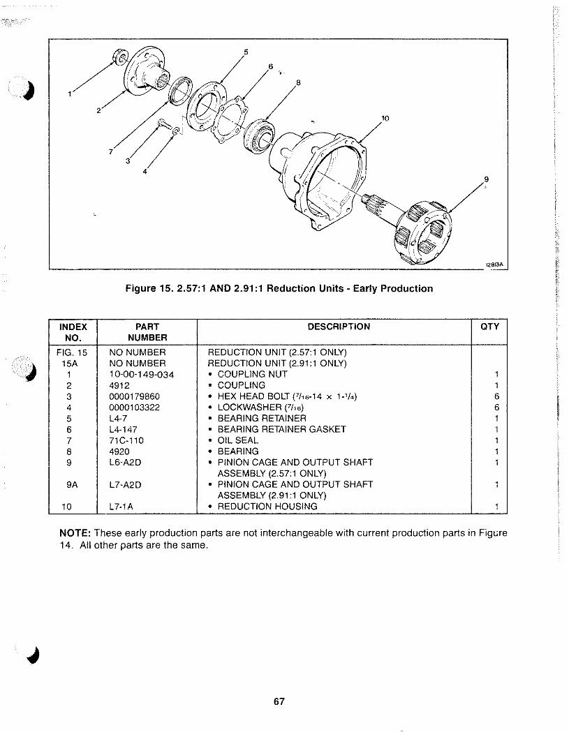
1
:/? 4
'--_________________________________ 1281M
Figure 15. 2.57:1 AND 2.91:1 Reduction Units· Early Production
INDEX PART DESCRIPTION OTY NO. NUMBER
FIG. 15 NO NUMBER REDUCTION UNIT (2.57:1 ONLY) 15A NO NUMBER REDUCTION UNIT (2.91:1 ONLY)
1 10-00-149-034 • COUPLING NUT 1 2 4912 • COUPLING
, , 3 0000179860 • HEX HEAD BOLT (7/16-14 x 1-'/4) 6 4 0000103322 • LOCKWASHER (7h6) 6 5 L4-7 • BEARING RETAINER 1 6 L4-147 • BEARING RETAINER GASKET 1 7 71C-110 • OIL SEAL 1 8 4920 • BEARING 1 9 L6-A2D • PINION CAGE AND OUTPUT SHAFT 1
ASSEMBLY (2.57:1 ONLY) 9A L7-A2D • PINION CAGE AND OUTPUT SHAFT 1
ASSEMBLY (2.91:1 ONLY) 10 L7-1A • REDUCTION HOUSING 1
NOTE: These early production parts are not interchangeable with current production parts in Figure 14. All other parts are the same.
67
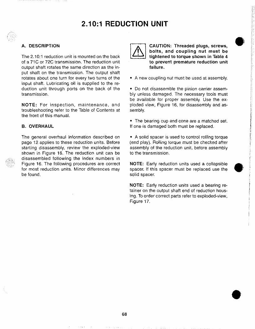
2.10:1 REDUCTION UNIT
A. DESCRIPTION
The 2.10;1 reduction unit is mounted on the back of a 71 Cor 72C transmission. The reduction unit output shaft rotates the same direction as the input shaft on the transmission. The output shaft rotates about one turn for every two turns of the input shaft. Lubricating oil is supplied to the reduction unit through ports on the back of the transmission.
NOTE: For inspection, maintenance, and troubleshooting refer to the Table of Contents at the front of this manual.
B. OVERHAUL
The general overhaul information described on page 12 applies to these reduction units. Before starting disassembly, review the exploded-view shown in Figure 16. The reduction unit can be disassembled following the index numbers in Figure 16. The following procedures are correct for most reduction units. Minor differences may be found.
68
CAUTION: Threaded plugs, screws, bolts, and coupling nut must be tightened to torque shown in Table 4 to prevent premature reduction unit failure.
• A new coupling nut must be used at assembly.
• Do not disassemble the pinion carrier assembly unless damaged. The necessary tools must be available for proper assembly. Use the exploded view, Figure 16, for disassembly and assembly.
• The bearing cup and cone are a matched set. If one is damaged both must be replaced.
• A solid spacer is used to control rolling torque (end play). Roiiing torque must be checked after assembly of the reduction unit, before assembly to the transmission.
•
NOTE: Early reduction units used a collapsible • spacer. If this spacer must be replaced use the solid spacer.
NOTE: Early reduction units used a bearing retainer on the output shaft end of reduction housing. To order correct parts refer to exploded-view, Figure 17.
•
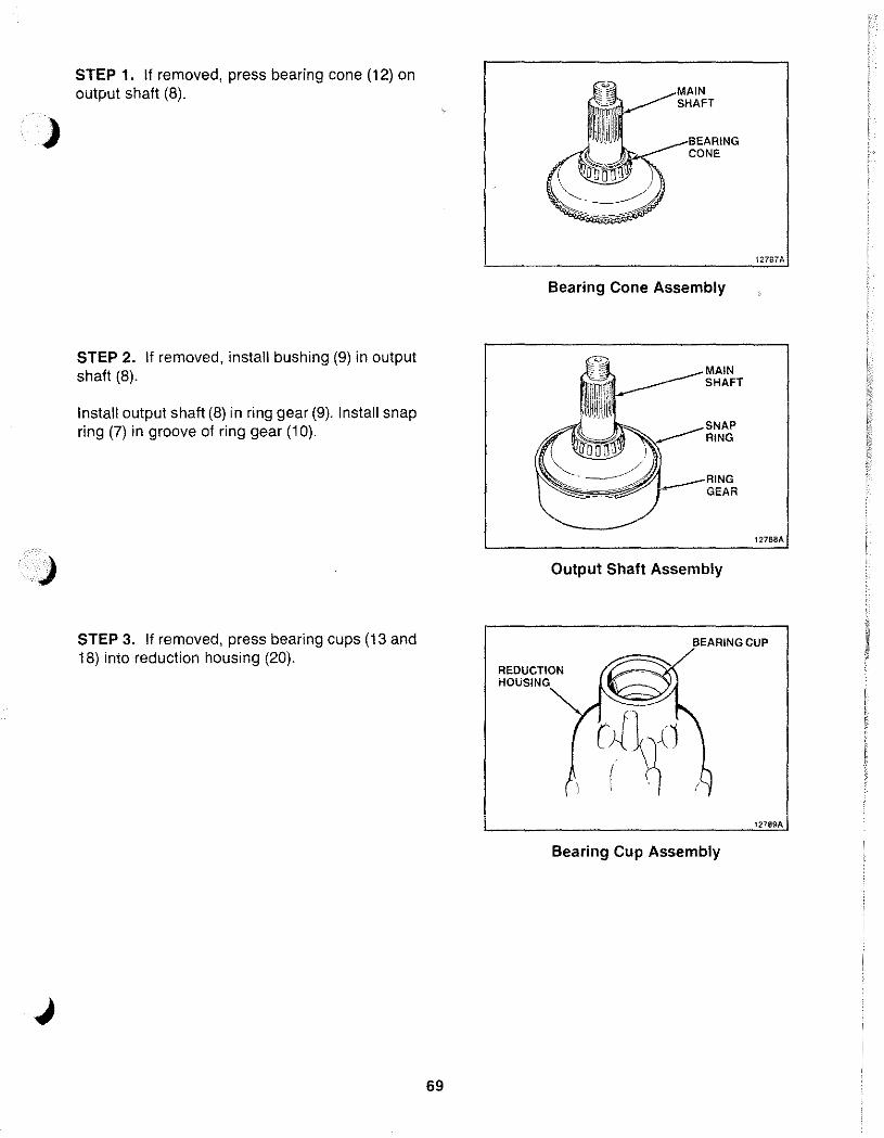
)
)
J
STEP 1. if removed, press bearing cone (12) on output shaft (8).
STEP 2. if removed, install bushing (9) in output shaft (8).
install output shaft (8) in ring gear (9). install snap ring (7) in groove of ring gear (10).
STEP 3. if removed, press bearing cups (13 and 18) into reduction housing (20).
69
Bearing Cone Assembly
MAIN SHAFT
RING
GEAR
Output Shaft Assembly
12787A
BEARING CUP
REDUCTiON HOUSING
Bearing Cup Assembly
12789A
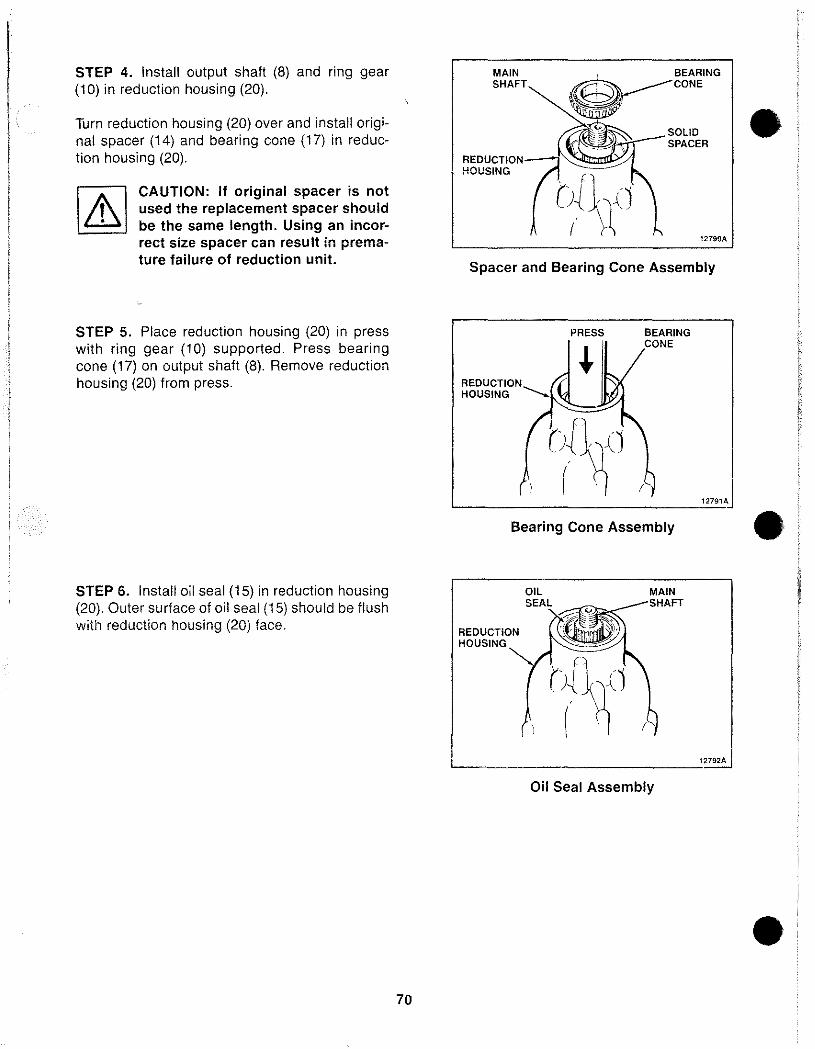
STEP 4. Install output shaft (8) and ring gear (10) in reduction housing (20).
Turn reduction housing (20) over and install original spacer (14) and bearing cone (17) in reduction housing (20).
CAUTION: If original spacer is not used the replacement spacer should be the same length. Using an incorrect size spacer can result in prema-ture failure of reduction unit.
STEP 5. Place reduction housing (20) in press with ring gear (10) supported. Press bearing cone (17) on output shaft (8). Remove reduction housing (20) from press.
STEP 6. Install oil seal (15) in reduction housing (20). Outer surface of oil seal (15) should be flush with reduction housing (20) face.
70
MAIN SHAFT
REDUCTION?,
~~'" j (~~ ~{1
SOLID SPACER
12790A
Spacer and Bearing Cone Assembly
REDUCTION HOUSING
PRESS BEARING CONE
Bearing Cone Assembly
REDUCTION HOUSING
MAIN SHAFT
Oil Seal Assembly
12791A
12792A
•
•
•
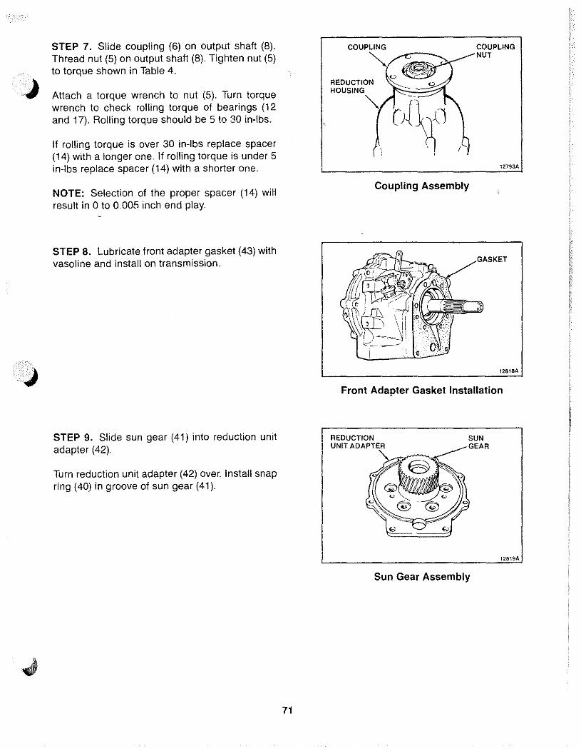
STEP 7. Slide coupling (6) on output shaft (8). Thread nut (5) on output shaft (8). Tighten nut (5) to torque shown in Table 4.
Attach a torque wrench to nut (5). Turn torque wrench to check rolling torque of bearings (12 and 17). Rolling torque should be 5 to 30 in-Ibs.
If rolling torque is over 30 in-Ibs replace spacer (14) with a longer one. If rolling torque is under 5 in-Ibs replace spacer (14) with a shorter one.
NOTE: Selection of the proper spacer (14) will result in 0 to 0.005 inch end play.
STEP 8. Lubricate front adapter gasket (43) with vasoline and install on transmission.
STEP 9. Slide sun gear (41) into reduction unit adapter (42).
Turn reduction unit adapter (42) over. Install snap ring (40) in groove of sun gear (41).
71
REDUCTION HOUSING
Coupling Assembly
COUPLING NUT
12793A
GASKET
12818A
Front Adapter Gasket Installation
REDUCTION UNIT
SUN GEAR
Sun Gear Assembly
12819A
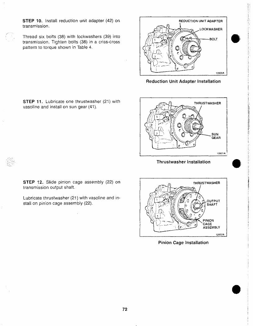
STEP 10. Install reduction unit adapter (42) on transmission.
Thread six bolts (38) with lockwashers (39) into transmission. Tighten bolts (38) in a criss·cross pattern to torque shown in Table 4.
STEP 11. Lubricate one thrustwasher (21) with vasoline and install on sun gear (41).
STEP 12. Slide pinion cage assembly (22) on transmission output shaft.
Lubricate thrustwasher (21) with vasoline and install on pinion cage assembly (22).
72
• Reduction Unit Adapter Installation
I 12821A 1
Thrustwasher Installation •
ASSEMBLY
12822A
Pinion Cage Installation
•
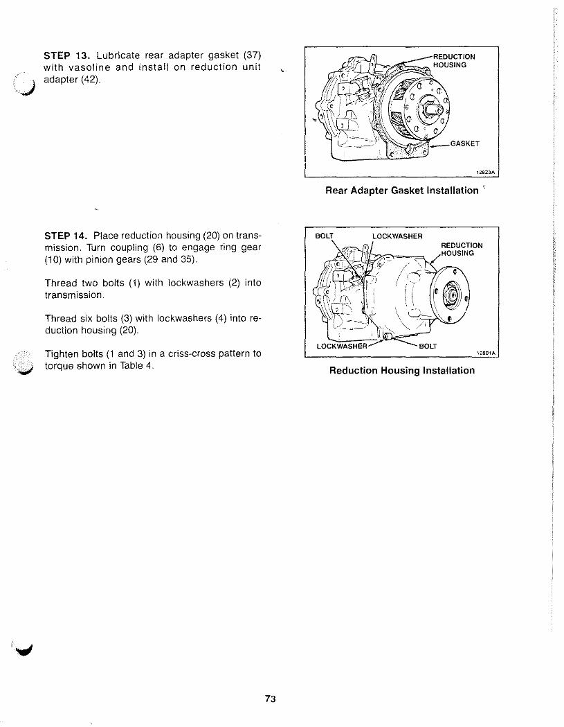
.. ~
STEP 13. Lubricate rear adapter gasket (37) with vasoline and install on reduction unit adapter (42) .
STEP 14. Place reduction housing (20) on transmission. Turn coupling (6) to engage ring gear (10) with pinion gears (29 and 35).
Thread two bolts (1) with lockwashers (2) into transmission.
Thread six bolts (3) with lockwashers (4) into reduction housing (20).
Tighten bolts (1 and 3) in a criss-cross pattern to • ....,1 torque shown in Table 4.
73
12823A
Rear Adapter Gasket Installation'
BOLT REDUCTION HOUSING
12801A
Reduction Housing Installation
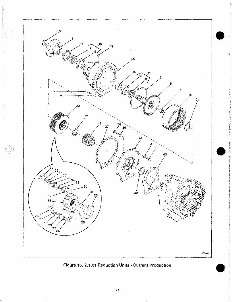
•
•
128148
Figure 16 2 .. 10·1R d . e uction Units· Curr ent Production • 74
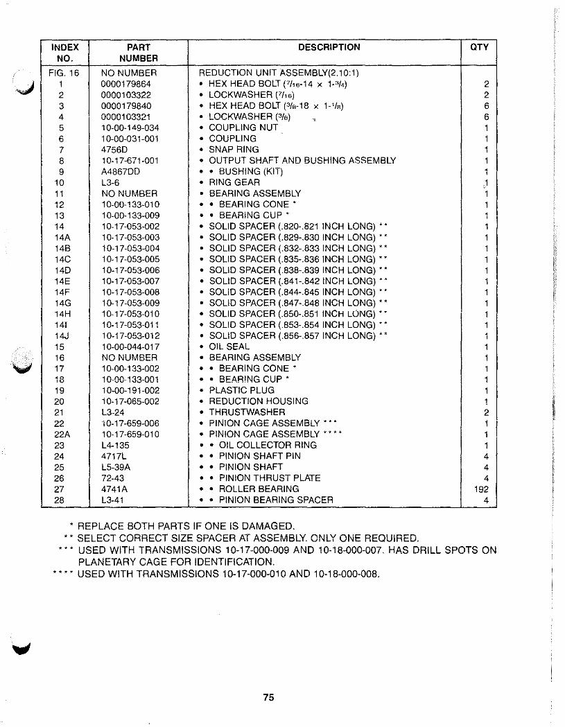
INDEX PART DESCRIPTION OTY NO. NUMBER
FIG. 16 NO NUMBER REDUCTION UNIT ASSEMBLY(2.10:1) 1 0000179864 • HEX HEAD BOLT (7/,6·14 X P/4) 2 2 0000103322 • LOCKWASHER (7/'6) 2 3 0000179840 • HEX HEAD BOLT (3/s·18 x 1-'/s) 6 4 0000103321 • LOCKWASHER (3/S) ~ 6 5 1 0-00-149-034 • COUPLING NUT 1 6 1 0-00-031-001 • COUPLING 1 7 47560 • SNAP RING 1 8 10-17-671-001 • OUTPUT SHAFT AND BUSHING ASSEMBLY 1 9 A4867DD • • BUSHING (KIT) 1
10 L3-6 • RING GEAR ,1 11 NO NUMBER • BEARING ASSEMBLY 1 12 10-00-133-010 • • BEARING CONE' 1 13 1 0-00-133-009 • • BEARING CUP' 1 14 10-17-053-002 • SOLID SPACER (.820-.821 INCH LONG) •• 1 14A 1 0-17-053-003 • SOLID SPACER (.829-.830 INCH LONG) •• 1 14B 10-17-053-004 • SOLID SPACER (.832-.833 INCH LONG) •• 1 14C 1 0-17-053-005 • SOLID SPACER (.835-.836 INCH LONG) •• 1 140 1 0-17-053-006 • SOLID SPACER (.838-.839 INCH LONG) •• 1 14E 10-17-053-007 • SOLID SPACER (.841-.842 INCH LONG) •• 1 14F 1 0-1 7-053-008 • SOLID SPACER (.844-.845 INCH LONG) •• 1 14G 1 0-17-053-009 • SOLID SPACER (.847-.848 INCH LONG) •• 1 14H 10-17-053-010 • SOLID SPACER (.850-.851 INCH LONG) •• 1 141 10-17-053-011 • SOLID SPACER (.853-.854 INCH LONG) •• 1 14J 10-17-053-012 • SOLID SPACER (.856-.857 INCH LONG) •• 1 15 10-00-044-017 • OIL SEAL 1 16 NO NUMBER • BEARING ASSEMBLY 1 17 10-00-133-002 • • BEARING CONE' 1 18 10-00-133-001 • • BEARING CUP' 1 19 1 0-00-191-002 • PLASTIC PLUG 1 20 1 0-17-065-002 • REDUCTION HOUSING 1 21 L3-24 • THRUSTWASHER 2 22 1 0-17-659-006 • PINION CAGE ASSEMBLY'" 1 22A 10-17-659-010 • PINION CAGE ASSEMBLy···· 1 23 L4-135 • • OIL COLLECTOR RING 1 24 4717L • • PINION SHAFT PIN 4 25 L5-39A • • PINION SHAFT 4 26 72-43 • • PINION THRUST PLATE 4 27 4741 A • • ROLLER BEARING 192 28 L3-41 • • PINION BEARING SPACER 4
* REPLACE BOTH PARTS IF ONE IS DAMAGED. * * SELECT CORRECT SIZE SPACER AT ASSEMBLY. ONLY ONE REQUIRED.
*** USED WITH TRANSMISSIONS 10-17-000-009 AND 10-18-000-007. HAS DRILL SPOTS ON PLANETARY CAGE FOR IDENTIFICATION.
* * * * USED WITH TRANSMISSIONS 10-17-000-010 AND 10-18-000-008.
75
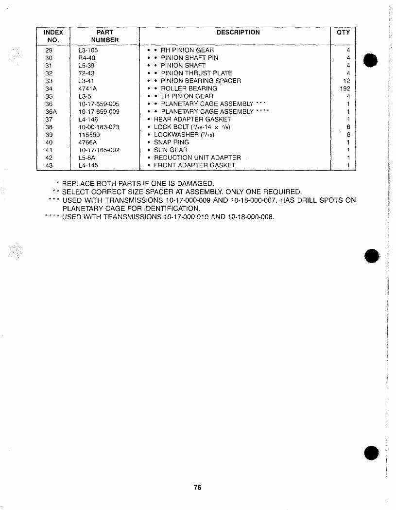
INDEX PART DESCRIPTION OTY NO. NUMBER
29 L3-105 • • RH PINION GEAR 4 30 R4-40 • • PINION SHAFT PIN 4 31 L5-39 • • PINION SHAFT 4 32 72-43 • • PINION THRUST PLATE 4 33 L3-41 • • PINION BEARING SfACER 12 34 4741A • • ROLLER BEARING 192 35 L3-5 • • LH PINION GEAR 4 36 10-17-659-005 • • PLANETARY CAGE ASSEMBLY'" 1 36A 10-17-659-009 • • PLANETARY CAGE ASSEMBLy···· 1 37 L4-146 • REAR ADAPTER GASKET 1 38 10-00-183-073 • LOCK BOLT (7/,6-14 X 7/8) 6 39 115550 • LOCKWASHER (7/16) 6 40 4766A • SNAP RING 1
-41 10-17-165-002 • SUN GEAR 1 42 L5-8A • REDUCTION UNIT ADAPTER 1 43 L4-145 • FRONT ADAPTER GASKET 1
• REPLACE BOTH PARTS IF ONE IS DAMAGED . •• SELECT CORRECT SIZE SPACER AT ASSEMBLY ONLY ONE REQUIRED.
*'. USED WITH TRANSMISSIONS 10-17-000-009 AND 10-18-000-007. HAS DRILL SPOTS ON PLANETARY CAGE FOR IDENTIFICATION .
.. * .. * USED vVITH TRANSMISSIONS 10-17-000-010 ,4ND 10-18-000-008.
76
•
•
•
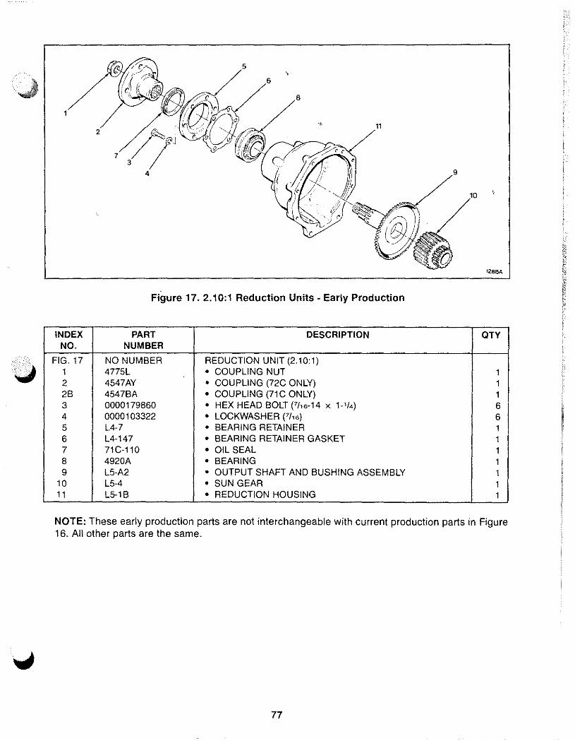
377~ 11
4
t2815A
Figure 17. 2.10:1 Reduction Units - Early Production
INDEX PART DESCRIPTION OTY NO. NUMBER
FIG,17 NO NUMBER REDUCTION UNIT (2,10:1) 1 4775L • COUPLING NUT 1 2 4547AY • COUPLING (72C ONLY) 1 2B 4547BA • COUPLING (71C ONLY) 1 3 0000179860 • HEX HEAD BOLT (7/16-14 x 1_1/4) 6 4 0000103322 • LOCKWASHER (7116) 6 5 L4·7 • BEARING RETAINER 1 6 L4-147 • BEARING RETAINER GASKET 1 7 71C-110 • OIL SEAL 1 8 4920A • BEARING 1 9 L5·A2 • OUTPUT SHAFT AND BUSHING ASSEMBLY 1
10 L5-4 • SUN GEAR 1 11 L5-1B • REDUCTION HOUSING 1
NOTE: These early production parts are not interchangeable with current production parts in Figure 16, All other parts are the same,
77
SERVICE NOTES
78

Form No_ 1289 2191
BorgWarner Marine & Industrial Transmissions
Distributed By:
Borg-Wamer Automotive Diversiffed Transmission Products Corporation
Borg.Warner Automotive GmbH
Marine & Industrial Transmissions
Marine & Industrial Transmissions
5401 Kilgore Avenue
Kenfig Industrial Estate Margam Hr. Port Talbot
-iJCopYfigh! Borg-Warner Manne and Industrial TransmiSSIons 1990
Muncie Indiana 47304
West Glamorgan SA132PG United Kingdom
Telephone 317/286·6100 Telex: 27·491 Fax: 317/286.6891
Telephone 656·741001 Telex: 85149861 Fax: 656·747811
•
•
•


![AkzoNobel Dulux Velvet Touch Emulsion€¦ · Dulux Dulux Dulux h Velvet TOUCh Velvet Touch DIAMOND PLATINUM GLO FINISH PEARL GLO FIN] NEW& IMPROVED rÅkZON0bel Dulux Velvet Touch](https://img.pdfslide.us/doc/110x75/61481ebecee6357ef92525b0/akzonobel-dulux-velvet-touch-emulsion-dulux-dulux-dulux-h-velvet-touch-velvet-touch.jpg)


![AkzoNobel Dulux Velvet Touch Emulsion… · PEARL GLO FIN] NEW& IMPROVED rÅkZON0bel Dulux Velvet Touch zoNobel DUIux Velvet PEARL GLO FINISH _ NEW&. IMPROVED Dulux Velvet Touch DIAMOND](https://img.pdfslide.us/doc/110x75/60a4cc2c64ba681d2238fa1f/akzonobel-dulux-velvet-touch-emulsion-pearl-glo-fin-new-improved-rkzon0bel.jpg)