Embed Size (px)
Citation preview
VELOCITY CONTROL OF A CAR-LIKE MOBILE ROBOT
By
TOP SOKUNPHAL
A Dissertation submitted for partial fulfilment of the requirement for
the degree of Master of Science (Electronic Systems Design
Engineering)
August 2017

ii
ACKNOWLEDGEMENTS
I really appreciate the following people who always encourage me, and support
me to pursue my master degree. I would say that without any supports from them, I cannot
finished this dissertation. They all are the part of my life. Therefore, I would like to give
my best gratitude to these people for giving me their time, their kindness, and expertise.
Firstly, I would like to express my deepest gratitude to my family, who always
stay by my side, guide, support, and encourage me since I was young until now. They
never complain about being tired to feed me. Sometimes I did not perform well on my
academic, but they never give up on me. They still cheer me up everyday and teach me
how to be strong in life. I am really proud to be his son.
Secondly, I would like to give a special thanks to my supervisor, Dr. Wan Amir
Faud Wajdi Othman, who always spends his time to give comments and checking my
report. Moreover, I am thankful for his guidance and encouragement to finish my
dissertation properly. Meanwhile, I would like to thank Mr. Mohamad Faiz Ahmad,
master of research student, who guided me the project, and helped me to setup the
experiment.
Lastly, I am very grateful to my government which sponsored me to pursue this
master degree. I am sure that I cannot finish my dissertation without sponsor from my
government. I would like to thank the dean, all lecturers, staffs in school of electrical and
electronic in USM for offering me a convenience to ease my study and research.

iii
TABLE OF CONTENTS
ACKNOWLEDGEMENTS .............................................................................................. ii
TABLE OF CONTENTS ................................................................................................. iii
LIST OF TABLES .......................................................................................................... vii
LIST OF FIGURES ....................................................................................................... viii
LIST OF ABBREVIATIONS ............................................................................................ x
ABSTRAK ........................................................................................................................ xi
ABSTRACT .................................................................................................................... xii
CHAPTER 1 INTRODUCTION ....................................................................................... 1
1.1. Overview ................................................................................................................. 1
1.2. Problem Statement .................................................................................................. 2
1.3. Objective ................................................................................................................. 3
1.4. Scope of Work ......................................................................................................... 3
1.5. Thesis Organization ................................................................................................. 4
CHAPTER 2 LITERATURE REVIEW ............................................................................ 6
2.1. Introduction ............................................................................................................. 6
2.2. Proportional Integral Derivative Controller Optimization ...................................... 6
2.3. Velocity Control of DC Motor Based on PID Controller ....................................... 9
2.3.1. Separately Excited DC Motor ......................................................................... 10
iv
2.3.2. Turning of PID Controller .............................................................................. 10
2.4. Maneuver Control System ..................................................................................... 13
2.4.1. Car-like Mobile Robot Control Design .......................................................... 13
2.4.2. Differential Drive ............................................................................................ 15
2.4.3. Skid Steering ................................................................................................... 18
2.5. Relative Error Calculation ..................................................................................... 20
2.6. Summary ............................................................................................................... 22
CHAPTER 3 METHODOLOGY .................................................................................... 23
3.1. Introduction ........................................................................................................... 23
3.2. Car-like Mobile Robot Concept ............................................................................ 25
3.2.1. Car-like Mobile Robot Movement .................................................................. 27
3.2.2. Car-like Mobile Robot Steering Direction...................................................... 27
3.3. Car-like Mobile Robot Control System Design .................................................... 28
3.3.1. DC Motor Model Verification ........................................................................ 29
3.3.2. Design Speed Controller ................................................................................. 33
3.3.3. Car-Like Robot Kinematic Model .................................................................. 36
3.4. Hardware Development ......................................................................................... 39
3.4.1. Arduino Mega ................................................................................................. 40
3.4.2. Rotary Encoder ............................................................................................... 43
3.4.3. Motor Driver ................................................................................................... 44

v
3.4.4. Transaxle Motor .............................................................................................. 45
3.4.5. Servo Motor .................................................................................................... 46
3.5. Summary ............................................................................................................... 48
CHAPTER 4 RESULTS AND DISCUSSION ................................................................ 49
4.1. Introduction ........................................................................................................... 49
4.2. Transfer Function of DC motor System ................................................................ 49
4.2.1. Time Constant ................................................................................................. 49
4.2.2. DC Gain .......................................................................................................... 51
4.3. Design Speed Controller ....................................................................................... 54
4.3.1. PI Controller Gains ......................................................................................... 54
4.3.2. Real-Time Testing using PI Controller ........................................................... 56
4.3.3. Comparison between Simulation and Real-time Testing ............................... 57
4.4. Car-like Robot Kinematic Model .......................................................................... 58
4.4.1. The Current Coordinate of Car-like Mobile Robot ........................................ 59
4.4.2. Car-like Mobile Robot Physical Experiment .................................................. 60
4.4.3. Comparison between Simulation and Physical Experiment ........................... 63
4.5. Summary ............................................................................................................... 64
CHAPTER 5 CONCLUSION .......................................................................................... 65
5.1. Conclusion ............................................................................................................. 65
5.2. Future work ........................................................................................................... 66
vi
REFERENCES ................................................................................................................. 67
APPENDIXES ................................................................................................................. 71
vii
LIST OF TABLES
Table 2-1 DC motor parameters (Suman & Kumar Giri, 2016) ...................................... 10
Table 2-2 Ziegler-Nichols turning rule based (Suman & Kumar Giri, 2016) .................. 10
Table 2-3 The effect of increasing the PID parameters (Suman & Kumar Giri, 2016) ... 11
Table 2-4 The error in degree of RMS dependent on scenario (Brückner et al., 2012) ... 21
Table 2-5 The sampling frequency influence on accuracy (Brückner et al., 2012) ......... 21
Table 3-1 The specification of Arduino Mega 2560 ........................................................ 41
Table 3-2 The specification of rotary encoder ................................................................. 43
Table 4-1 Relation between PWM and Steady State Velocity ........................................ 51

viii
LIST OF FIGURES
Figure 2.1. The structure of DC motor position servo ....................................................... 7
Figure 2.2. (a) A simple PID output response curve, (b) An expert PID output................ 8
Figure 2.3. The PID controller system ............................................................................. 11
Figure 2.4. GA optimization progression based objective function (IAE) index ........... 12
Figure 2.5. Step response of PID with GA and without GA ............................................ 12
Figure 2.6. The bicycle model of Car-like mobile robot.................................................. 14
Figure 2.7. Simulink block of fuzzy PID controller......................................................... 15
Figure 2.8. Mobile robot configuration and motion coordinate ....................................... 16
Figure 2.9. (a) Trajectory tracking without controller, (b) Trajectory tracking, (c)
Trajectory tracking with controller and observer ............................................................. 17
Figure 2.10. An entire cycle measurement using laser scanner ....................................... 19
Figure 3.1. The process of overall system ....................................................................... 23
Figure 3.2. The body of car-like mobile robot and hardware attachment (a) Top view, (b)
Side view, (c) motor attachement..................................................................................... 25
Figure 3.3. The completed car-like mobile robot for physical experiment ...................... 26
Figure 3.4. The process flow of control system method .................................................. 29
Figure 3.5. The schematic representation of the considered DC motor ........................... 30
Figure 3.6. A block diagram of the DC motor ................................................................. 31
Figure 3.7. Block diagram of DC motor in Simulink ...................................................... 33
Figure 3.8. Block diagram of speed controller ................................................................. 34
Figure 3.9. PI controller block diagram in Simulink ....................................................... 35
ix
Figure 3.10. car-like mobile robot block diagram............................................................ 37
Figure 3.11. Car-like mobile robot implemented block diagram ..................................... 38
Figure 3.12. The Arduino MEGA 2560 board ................................................................. 40
Figure 3.13. The schematic diagram of Microcontroller system ..................................... 42
Figure 3.14. The physical of Rotary encoder ................................................................... 44
Figure 3.15. Motor driver MD30C ................................................................................... 45
Figure 3.16. Transaxle motor PPSM63L-01 .................................................................... 46
Figure 3.17. RC servo motor HD-1051MG ..................................................................... 47
Figure 4.1. The relation between velocity and running time ........................................... 50
Figure 4.2. The relation between 10 steady state velocities and PWM ........................... 52
Figure 4.3. The velocity of motor according to transfer function .................................... 53
Figure 4.4. The velocity by using PI controller ............................................................... 55
Figure 4.5. The velocity by testing the robot with PI controller ...................................... 56
Figure 4.6. The simulation and measured velocity using PI controller ........................... 58
Figure 4.7. The X-Y coordinate of car-like mobile robot kinematic model .................... 59
Figure 4.8. The direction of the car-like robot kinematic model ................................... 60
Figure 4.9. The X-Y coordinate in real-time experiment................................................. 61
Figure 4.10. The direction in real-time experiment ..................................................... 62
Figure 4.11. The comparison between simulation and measured velocity ...................... 63
x
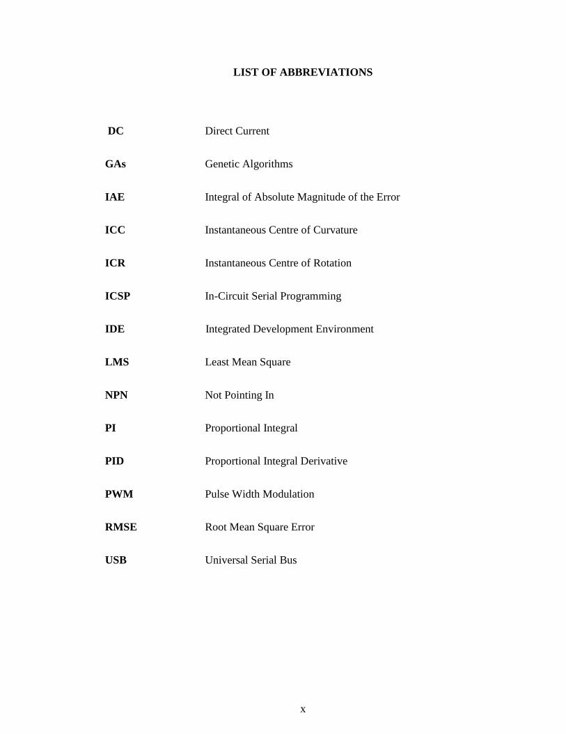
LIST OF ABBREVIATIONS
DC Direct Current
GAs Genetic Algorithms
IAE Integral of Absolute Magnitude of the Error
ICC Instantaneous Centre of Curvature
ICR Instantaneous Centre of Rotation
ICSP In-Circuit Serial Programming
IDE Integrated Development Environment
LMS Least Mean Square
NPN Not Pointing In
PI Proportional Integral
PID Proportional Integral Derivative
PWM Pulse Width Modulation
RMSE Root Mean Square Error
USB Universal Serial Bus
xi
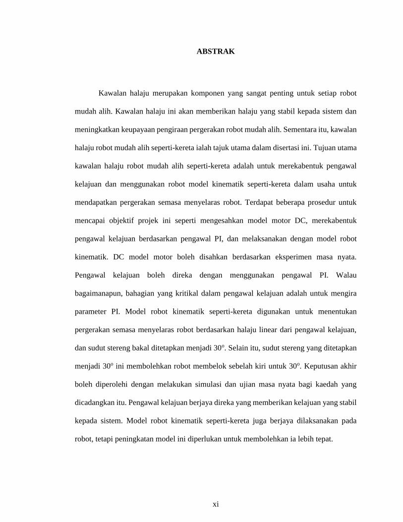
ABSTRAK
Kawalan halaju merupakan komponen yang sangat penting untuk setiap robot
mudah alih. Kawalan halaju ini akan memberikan halaju yang stabil kepada sistem dan
meningkatkan keupayaan pengiraan pergerakan robot mudah alih. Sementara itu, kawalan
halaju robot mudah alih seperti-kereta ialah tajuk utama dalam disertasi ini. Tujuan utama
kawalan halaju robot mudah alih seperti-kereta adalah untuk merekabentuk pengawal
kelajuan dan menggunakan robot model kinematik seperti-kereta dalam usaha untuk
mendapatkan pergerakan semasa menyelaras robot. Terdapat beberapa prosedur untuk
mencapai objektif projek ini seperti mengesahkan model motor DC, merekabentuk
pengawal kelajuan berdasarkan pengawal PI, dan melaksanakan dengan model robot
kinematik. DC model motor boleh disahkan berdasarkan eksperimen masa nyata.
Pengawal kelajuan boleh direka dengan menggunakan pengawal PI. Walau
bagaimanapun, bahagian yang kritikal dalam pengawal kelajuan adalah untuk mengira
parameter PI. Model robot kinematik seperti-kereta digunakan untuk menentukan
pergerakan semasa menyelaras robot berdasarkan halaju linear dari pengawal kelajuan,
dan sudut stereng bakal ditetapkan menjadi 30o. Selain itu, sudut stereng yang ditetapkan
menjadi 30o ini membolehkan robot membelok sebelah kiri untuk 30o. Keputusan akhir
boleh diperolehi dengan melakukan simulasi dan ujian masa nyata bagi kaedah yang
dicadangkan itu. Pengawal kelajuan berjaya direka yang memberikan kelajuan yang stabil
kepada sistem. Model robot kinematik seperti-kereta juga berjaya dilaksanakan pada
robot, tetapi peningkatan model ini diperlukan untuk membolehkan ia lebih tepat.
xii
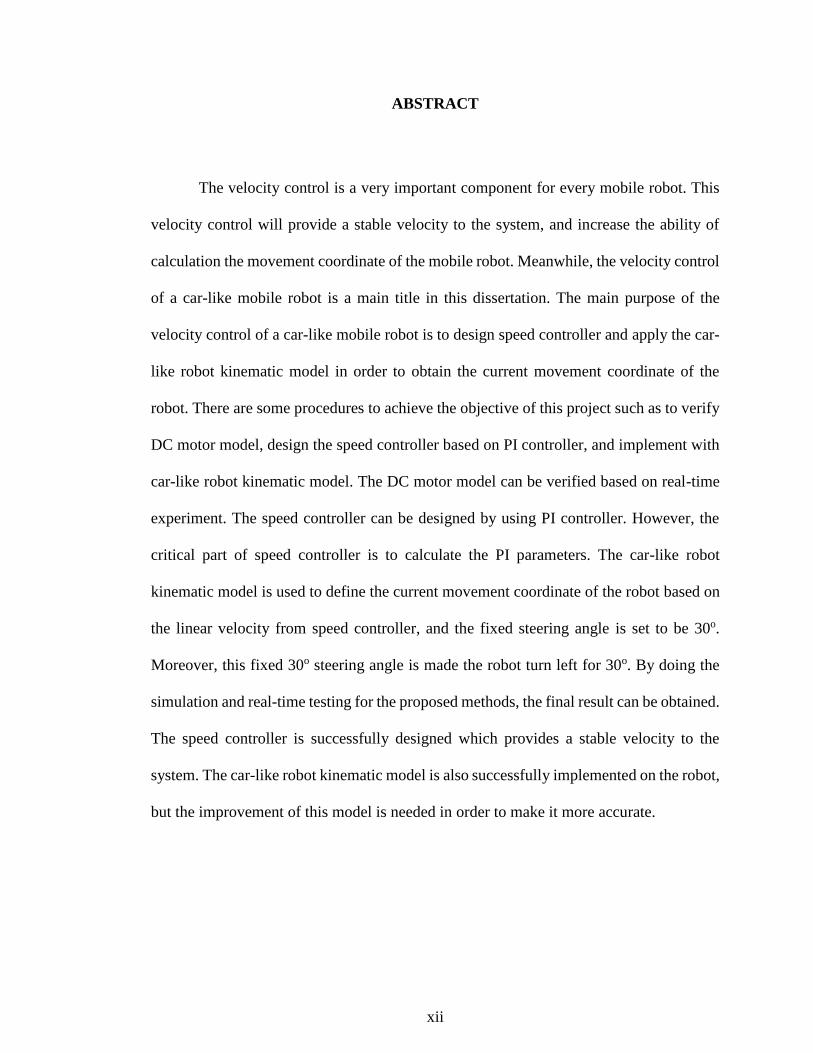
ABSTRACT
The velocity control is a very important component for every mobile robot. This
velocity control will provide a stable velocity to the system, and increase the ability of
calculation the movement coordinate of the mobile robot. Meanwhile, the velocity control
of a car-like mobile robot is a main title in this dissertation. The main purpose of the
velocity control of a car-like mobile robot is to design speed controller and apply the car-
like robot kinematic model in order to obtain the current movement coordinate of the
robot. There are some procedures to achieve the objective of this project such as to verify
DC motor model, design the speed controller based on PI controller, and implement with
car-like robot kinematic model. The DC motor model can be verified based on real-time
experiment. The speed controller can be designed by using PI controller. However, the
critical part of speed controller is to calculate the PI parameters. The car-like robot
kinematic model is used to define the current movement coordinate of the robot based on
the linear velocity from speed controller, and the fixed steering angle is set to be 30o.
Moreover, this fixed 30o steering angle is made the robot turn left for 30o. By doing the
simulation and real-time testing for the proposed methods, the final result can be obtained.
The speed controller is successfully designed which provides a stable velocity to the
system. The car-like robot kinematic model is also successfully implemented on the robot,
but the improvement of this model is needed in order to make it more accurate.
1
CHAPTER 1
INTRODUCTION
1.1. Overview
In the previous years, investigation and development of the autonomous mobile
robot are increasing gradually in many fields such as in military, industries, and hospital.
The concept of mobility which basically suggested whereby mobility is free-roaming
robots move about with an integrated multifariousness fostering even more preponderant
returns in extra range of application surpass that of the typical factor floor.
In the past years, mobile robots were designed with large size, heavy and require
a high cost computer system which need to be connected via cable or wireless devices.
Nowadays, the trend is to evolve with a small mobile robot which is reduced in size,
weigh, and cost of the system by using sensors, numerous actuators, and the controller are
carried on-board the robot (Bräunl, 2008). Mobile robots are built based on a good relation
of both hardware and software. There is one more thing that mobile robot really needs is
a good navigation system such as vision camera or sensor. (Chen & Agrawal, 2013).
In this project, the mobile robot is developed to move by using car-like robot
kinematic model. This mobile robot will move forward with the stable speed which is
provided by the speed controller. Moreover, car-like robot kinematic model will let the
robot turn left or right according to the linear velocity provided by speed controller and a
fixed steering angle. The speed is provided for the mobile robot in range between 9.99cm/s
(0.36km/h) to 88.7cm/s (3.2km/h).
2
According to the mobile robot which is designed with a simple velocity control by
adjusting the PWM faces the problem during movement such as the mobile robot cannot
keep moving straight and difficult for direction control like turning left or right. Therefore,
the speed controller and car-like robot kinematic model are introduced in this project to
make the mobile robot has a high efficient on maneuver system.
Furthermore, this project also provides a lot of conveniences for development
purpose to reach a high level mobile robot. The mobile robot can be developed by making
a communication with various sensors and artificial intelligence. Moreover, the mobile
robot can be interacted with human, wheelchair, and other mobile robots as well.
Therefore, the project has many benefits for control system purpose and society.
1.2. Problem Statement
Nowadays, there are so many type of mobile robot. The movement and the
constraint of development are very important for every mobile robot. Some mobile robots
are designed by using the proper control method and the others comes with a simple
control method by adjusting velocity to make the robot move which has many problems
during movement of the robot.
There are some motion problems can be found on the mobile robot which is using
a simple control method. Firstly, the mobile robot cannot keep moving straight line due to
the speed provided by DC motor is not stable. This matter also makes the robot has the
difficulty to turn left or right by direction set or by using various sensor.
3
Therefore, the speed controller and car-like robot kinematic model are being used
in this project which known as the proper control system method. The speed controller
will provide a stable velocity to the robot, and car-like robot kinematic model will control
the movement of the robot by using the reference velocity from the speed controller and
the steering angle to control the direction of the robot. The advantage of the car-like robot
cinematic model is required only one DC motor and provides the current coordinate of the
robot.
1.3. Objective
The car-like robot is a type of mobile robot where the velocity and steering angle
are needed in order to get current coordinate of the robot. Therefore, there are two main
objectives to control velocity for car-like robot.
• To design the speed controller by using PI controller for car-like mobile robot.
• To implement the maneuver control system by using car-like robot kinematic
model.
1.4. Scope of Work
To achieve the objectives, DC motor model identification is needed to be done at
the first place to define transfer function of DC motor in this project. The main goal is to
define transfer function parameters such as DC gain and time constant. Another necessary
part is to design speed controller for car-like mobile robot by using PI controller. This
speed controller has enough ability to provide a stable velocity to the system. Therefore,
experiments are carried out in order to verify that the speed controller is successfully
designed.
4
Moreover, car-like robot kinematic model is used as a maneuver control method
to calculate current coordinate of car-like robot based on the motion equation of car-like
robot. By using car-like robot model, reference velocity and steering angle are needed to
be input for the system. The distance between front wheels and back wheels is very
necessary in this model due to the motion model of car-like robot.
Furthermore, the experiment for car-like robot model must be done to guarantee
that the robot moves are matched with the defined coordinates on simulation. The
calculation real-time coordinate of car-like robot is done by using Odomertry method.
However, the comparison between simulation result and real-time testing of the robot are
needed to be considered to verify that the car-like robot model can be used for this system.
1.5. Thesis Organization
There are five chapters in this dissertation such as introduction, literature review,
methodology, result and discussion, and conclusion. The briefly explanation for every
chapters can be found in this section, which start with chapter 1 until chapter 5. This
section also show about the outline in this dissertation.
Chapter 1 is shown about introduction, which describes about the overview of
related work, problem statement that express about the problem of using the simple
velocity control to drive the robot, goal and objectives that need to achieve in this project,
and scope of work which set to be done to achieve goal and objectives.
Chapter 2 shows literature review which provides some main information and
result from relevant research. Those information is related to technique and method that

5
have been using for relevant inventions. Moreover, this chapter will briefly explain about
the result of those relevant research. According to those results, the contribution of those
technique to this project can be confirmed.
Chapter 3 discusses about methodology, which describes about method and
technique that have been used in this entire project. Furthermore, all concepts that show
about how those techniques work and how to conduct the experiment are found in this
chapter. Hardware and software section are also explained in this chapter.
Chapter 4 explains about results and discussion for velocity control of car-like
mobile robot. All the completed results which is done by simulation and real-time testing
are described in this chapter. Moreover, this chapter is also explained about how to the
result contribute to the entire project.
Chapter 5 is a conclusion section, which concludes all the important information,
and what have been done in this project. In addition, this chapter also provides some good
idea to improve the ability of using car-like robot kinematic model as a main maneuver
control method in this project.
6
CHAPTER 2
LITERATURE REVIEW
2.1. Introduction
The relevant theories and precious research available which related to velocity
control of car-like mobile robot are described in this chapter. There are some important
techniques and relevant research available such as proportional integral derivative (PID)
controller, velocity control of DC motor by using both PI and PID controller, maneuver
control system, and the relative error calculation. Moreover, car-like robot control system
design, differential drive, and skid steering are found in maneuver control system.
2.2. Proportional Integral Derivative Controller Optimization
Proportional integral derivative (PID) control is one of the most efficient and
commonly use in robotic field. PID controller compares the measure output and the speed.
During the speed of the robot is low, the proportional control will increase the duty cycle.
This proportional control is very important parameter in PID controller in order stable the
system.
Derivative control will response to reduce the duty cycle, in case the speed raise
too fast. Duty cycle will be effected by proportional, integral, and derivative control.
According to the closed-loop control, the turning point must be very accurate based on the
set points and the process variable (Saidonr et al., 2011).
7
According to the simple formation and implementation, PID controller is well
known in control system field. The fundamental of PID controller is to define and optimize
the PID parameters. Recently, there are a lot of researches introduce intelligent control to
PID controller. This mean that the intelligence PID is built based on control process and
control law, or optimal problems with a smooth space of continuous derivatives.
Furthermore, the PID parameters optimization using genetic algorithm technique
has been applied to PID controller by many scholars (Aly, 2011). In addition, the
optimization of the PID controller parameters using genetic algorithm is applied to control
servo drive system of the mobile robot. The structure of DC motor position servo is shown
in Figure 2.1.
Figure 2.1. The structure of DC motor position servo
(Yan-hong et al., 2011)
In this research, the proposed method proved that the optimization of PID
parameter for servo motor is solved. Furthermore, the intelligent algorithm is applied in
PID controller for DC motor. There are three procedures to prove that the proposed
method is right to apply to the whole system.
8
Firstly, reverse error neural network is adopted to identify the mathematical model
of the robot drive. Secondly, the genetic algorithm is applied to define PID controller
parameter based on the identification model. Finally, the proposed method is implemented
to the mobile robot (Yan-hong et al., 2011).
Meanwhile, another method is proposed as an expert PID controller which
combine the position error and error of change output to correct the PID parameters for
mobile robot. The mobile robot is designed based on photoelectric sensor to detect the
white background and black middle line to reach the goal stable and fast. MATLAB is a
software which is used for simulation purpose (Luo & Li, 2014).
The simple output response curve using a simple PID control is shown in Figure
2.2 (a). By adding expert PID control to the system, the output response curve is presented
in Figure 2.2 (b). As the result, an expert PID controller has a good performance, high
reliability and good for tracking mobile robot automatically.
(a) (b)
Figure 2.2. (a) A simple PID output response curve, (b) An expert PID output
(Luo & Li, 2014)
9
2.3. Velocity Control of DC Motor Based on PID Controller
The DC motor is a necessary component for every mobile robots. The velocity
control is one of the most important part in order to provide a stable velocity to the system.
According to the previous research, there are a lot of techniques which are used to control
velocity of DC motor. However, PID controller is most common choice as a main
controller for velocity control of DC motor. This section is described about velocity
control of DC motor by using optimization techniques based on PID controller.
PID controller is well known as a control which is used to control speed and
position of DC motor framework. In this research, genetic algorithms (GAs) are used to
optimize the PID gains for speed controller of a DC motor. Genetic Algorithms are a
stochastic general pursue procedure that simulate the strategy of standard change
(Pavankumar et al., 2010). Moreover, PID controller is utilized due to its simple control
structure is very simple and less expensive (Visioli, 2012).
According to the execution of generic algorithms, the best tuning of PID
controllers parameters can be obtained. During the execution records, the ideal PID
controller analyzed the extension values by using GAs. The Integral of Absolute
Magnitude of the error (IAE) is settled to provide a best PID controller. The proposed
method was demonstrated with a second request physical plant as DC motor, where the
PID turning parameters calculations were driven for the most part.
10
2.3.1. Separately Excited DC Motor
The separately excited DC motor provide a speed to the system by using armature
control and the voltage apply to armature. The best rate for outline, position, speed are
given by DC motor. The block diagram of DC motor can be designed on MATLAB
Simulink. Furthermore, MATLAB Simulink is also used to get a step response for DC
motor. The parameters of DC motor is shown in Table 2.1.
Table 2-1 DC motor parameters (Suman & Kumar Giri, 2016)
2.3.2. Turning of PID Controller
In this research, the PID parameters can be calculated by using the Ziegler-Nichols
tuning rules. By using the Ziegler-Nichols, the relative coefficient is known as a definitive
addition the discrete reactions of a DC motor. Furthermore, the scattering and creation can
fixed the execution of standard controllers. The Ziegler-Nichols tuning rule parameters
based is shown in Table 2.2.
Table 2-2 Ziegler-Nichols turning rule based (Suman & Kumar Giri, 2016)
Controller Type KP KI KD
PID Ku/1.7 Tu/2 Tu/8
Parameters Value
Armature inductance
Armature resistance
Rotor inertia
Armature voltage
Viscous friction coefficient
Motor torque constant
Back EMF constant
Speed
La=0.1215 H
Ra=11.2 Ohm
Jm=0.02215 kg/m2
Va=240 V
Bm=0.002953 Nms/rad
Km=1.28 Nm/A
Kb=1.28 Vs/rad
W=1500 rpm

11
The goal of this technique is to get the PID parameters which match the execution
purpose such as settling time, rising time, overshoot, and the steady condition commit
error. According to the relation between DC motor and PID controller, the block diagram
of PID controller system can be designed as shown in Figure 2.3, which e is an error
signal, KP is a proportional gain, KI is an integral gain, and KD is a derivative gain.
Moreover, the effect of increasing the PID controller parameters is shown in Table 2.3.
Figure 2.3. The PID controller system
(Suman & Kumar Giri, 2016)
Table 2-3 The effect of increasing the PID parameters (Suman & Kumar Giri, 2016)
Parameter Rise Time Overshoot Settling
Time
Steady state
error
KP Decrease Increase Small change Decrease
KI Decrease Increase Increase Reduce
KD Small change Decrease Decrease Small change
However, the conventional PID controller tuning method which is used to obtained
a standard parameters of PID controller can be demonstrated by using MATLAB.
12
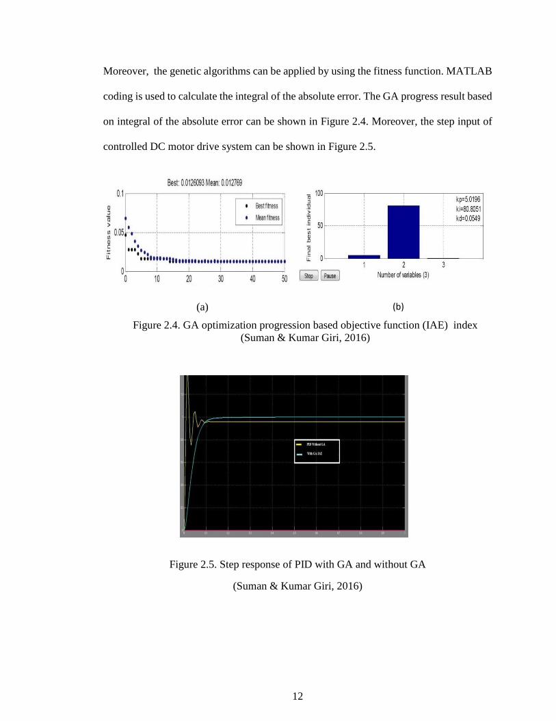
Moreover, the genetic algorithms can be applied by using the fitness function. MATLAB
coding is used to calculate the integral of the absolute error. The GA progress result based
on integral of the absolute error can be shown in Figure 2.4. Moreover, the step input of
controlled DC motor drive system can be shown in Figure 2.5.
Figure 2.5. Step response of PID with GA and without GA
(Suman & Kumar Giri, 2016)
(a) (b)
Figure 2.4. GA optimization progression based objective function (IAE) index
(Suman & Kumar Giri, 2016)
13
The final result in this research proved that the standard PID controller didn’t
provide the accurate result. The best result is obtained by using another technique to
control velocity of DC motor which is called genetic algorithms based PID controller. By
using GA based on PID controller, the PID parameters can be defined based on distinctive
target work, this tuning technique to get least ascent time, and the small steady state error
of settling time and overshoot (Suman & Kumar Giri, 2016).
2.4. Maneuver Control System
Recently, autonomous mobile robot provides a lot of advantages to industrial,
military, home, and other research centers. Maneuver control system is well known as a
main role to control the navigation of autonomous mobile robot. There are some
researches that related to maneuver control method such as car-like mobile robot,
differential kinematic, and skid steering, will be reviewed in this section.
2.4.1. Car-like Mobile Robot Control Design
Recently, the navigation of an autonomous mobile robot is the primary topic to
consider in the robotic field. The collision between the desire position and obstacle is the
matter of navigation (Kloetzer & Belta, 2008). The relevant researches such as a simple
dynamic and complicated dynamic are appeared in this area. The most common of
research on path planning for mobile robots is simple robot dynamic, either fully actuated
or under actuated with differential-wheel drive concept.

14
According to a high efficiency result, a realistic idea from large scale mobile robots
is to focus on car-like robots. Car-like robot is one of the most effective motion control
method which is used to control the wheels of the robot. The mathematical models are
usually used in a fixed frame environment or in frame where the robot moves to the desired
path (Kloetzer & Ghita, 2010). According to linear control theory, the adaptive control
system is designed to follow the path of car-like mobile robot. PID controller is used to
control the path following of the robot (Sanchez-lopez et al., 2012).
However, the fuzzy PID controller for the path following of a Car-like mobile
robot is proposed to improve performance of using only PID controller. To achieve this
method, there are two important things need to consider which include the kinematic
model of Car-like mobile robot, fuzzy PID controller and its features. The bicycle model
of Car-like robot is presented in Figure 2.6.
Figure 2.6. The bicycle model of Car-like mobile robot
(Siciliano, Khatib, & Groen, 2011)
15
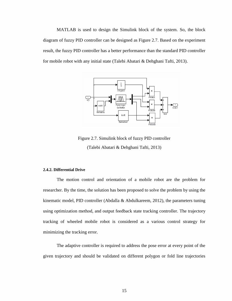
MATLAB is used to design the Simulink block of the system. So, the block
diagram of fuzzy PID controller can be designed as Figure 2.7. Based on the experiment
result, the fuzzy PID controller has a better performance than the standard PID controller
for mobile robot with any initial state (Talebi Abatari & Dehghani Tafti, 2013).
Figure 2.7. Simulink block of fuzzy PID controller
(Talebi Abatari & Dehghani Tafti, 2013)
2.4.2. Differential Drive
The motion control and orientation of a mobile robot are the problem for
researcher. By the time, the solution has been proposed to solve the problem by using the
kinematic model, PID controller (Abdalla & Abdulkareem, 2012), the parameters tuning
using optimization method, and output feedback state tracking controller. The trajectory
tracking of wheeled mobile robot is considered as a various control strategy for
minimizing the tracking error.
The adaptive controller is required to address the pose error at every point of the
given trajectory and should be validated on different polygon or fold line trajectories

16
(CAO, ZHAO, & WU, 2011). Differential drive for a mobile robot is used to control the
direction of the robot based on the differential between the speed of left and right wheel.
Normally, the differential drive is applied to the three-wheel’s robot which two
wheels are drive the robot and another one wheel is for supporting the robot. The
differential drive model is not based only on specific inputs and outputs, but also on how
and where the frame coordinates are accomplished (Diaz & Kelly, 2016). The mobile
robot configuration and motion coordinate are show in Figure 2.8.
Figure 2.8. Mobile robot configuration and motion coordinate
(Chandra & Mija, 2016)
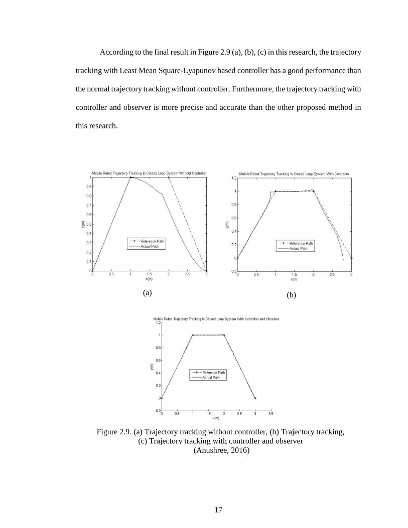
By using the proposed method, the result of trajectory tracking without controller
in closed loop system is shown in Figure 2.9 (a). While the trajectory tracking with
controller in the same closed loop system is presented in Figure 2.9 (b). Moreover, the
trajectory tracking with controller and observer in closed loop system is obtained, as
Figure 2.9 (c) (Anushree, 2016).
17
According to the final result in Figure 2.9 (a), (b), (c) in this research, the trajectory
tracking with Least Mean Square-Lyapunov based controller has a good performance than
the normal trajectory tracking without controller. Furthermore, the trajectory tracking with
controller and observer is more precise and accurate than the other proposed method in
this research.
(a) (b)
(c) Figure 2.9. (a) Trajectory tracking without controller, (b) Trajectory tracking,
(c) Trajectory tracking with controller and observer
(Anushree, 2016)
18
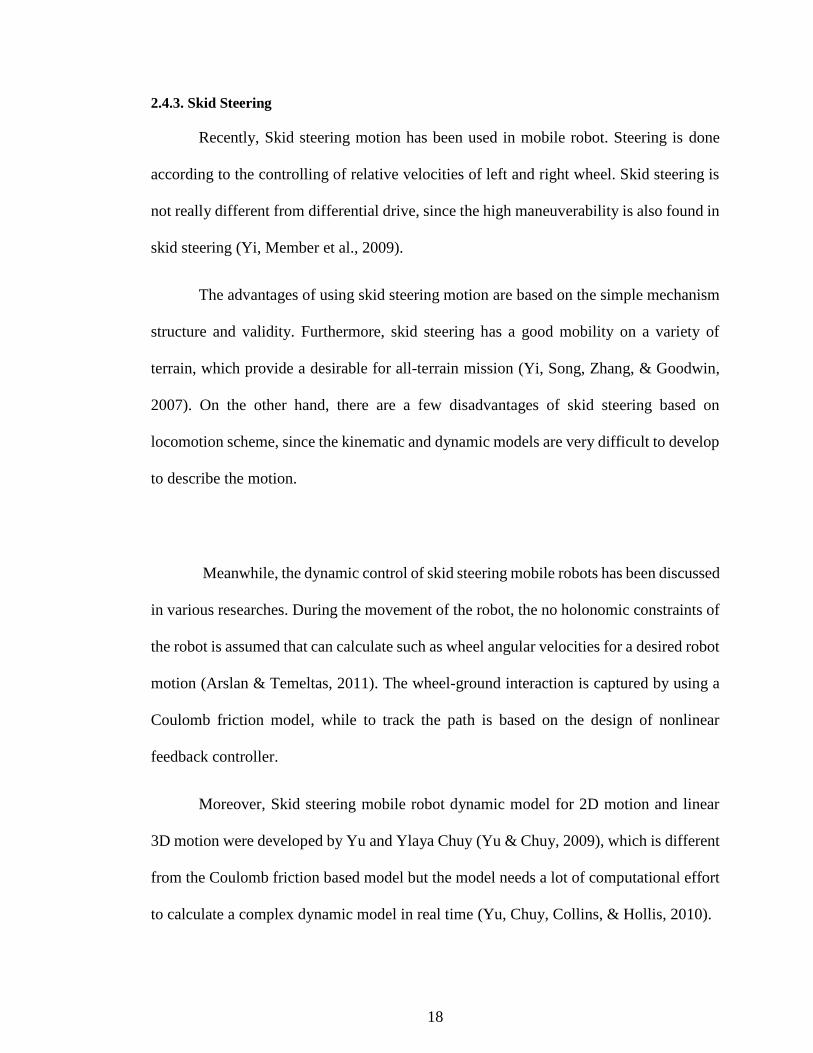
2.4.3. Skid Steering
Recently, Skid steering motion has been used in mobile robot. Steering is done
according to the controlling of relative velocities of left and right wheel. Skid steering is
not really different from differential drive, since the high maneuverability is also found in
skid steering (Yi, Member et al., 2009).
The advantages of using skid steering motion are based on the simple mechanism
structure and validity. Furthermore, skid steering has a good mobility on a variety of
terrain, which provide a desirable for all-terrain mission (Yi, Song, Zhang, & Goodwin,
2007). On the other hand, there are a few disadvantages of skid steering based on
locomotion scheme, since the kinematic and dynamic models are very difficult to develop
to describe the motion.
Meanwhile, the dynamic control of skid steering mobile robots has been discussed
in various researches. During the movement of the robot, the no holonomic constraints of
the robot is assumed that can calculate such as wheel angular velocities for a desired robot
motion (Arslan & Temeltas, 2011). The wheel-ground interaction is captured by using a
Coulomb friction model, while to track the path is based on the design of nonlinear
feedback controller.
Moreover, Skid steering mobile robot dynamic model for 2D motion and linear
3D motion were developed by Yu and Ylaya Chuy (Yu & Chuy, 2009), which is different
from the Coulomb friction based model but the model needs a lot of computational effort
to calculate a complex dynamic model in real time (Yu, Chuy, Collins, & Hollis, 2010).
19
The new analysis and experimental kinematic scheme of the skid-steering robot
by using a kinematic relationship between the instantaneous center of curvature (ICC)
coefficient of the robot and the path parameters are proposed later based on laser scanner
sensor. The laser scanner sensor is used to derive the ICR value of the robot and the other
path parameters in the experiment (Wang et al., 2015). The Figure 2.10 shows about the
laser scanner measurement during an entire cycle.
Figure 2.10. An entire cycle measurement using laser scanner
(Wang et al., 2015)
According to final of this research, the relationship between the skid steering
kinematic model and ICC coefficient of the robot and the path parameters has been done
by analysis and experimental. According to the experimental, the proposed model and the
analysis can be used to control the robot. Furthermore, the kinematic model is verified
that can be used for a skid steering robot system.
20
2.5. Relative Error Calculation
A relative error between absolute data and observe data is very important in every
research. The goodness of fit is a statistical model describes how it fits a set of observation.
The predicted values close to the observed data values is known as a well-fitting regression
model. Normally, the fit of a proposed regression is better than the fit of the mean model.
There are three goodness of fit statistical model are used in ordinary least squares (OLS)
regression to evaluate the fitness of model such as R-Square, the overall F-test, and the
root mean square error (RMSE) (R-squared & R-squared, 2012).
The RMSE is the square root which measure of how close a fitted line is to data
points. This mean that the absolute fit of the model to the data and how observed data
close to the model’s predicted values. The RMSE is interpreted in term of measurement
units, and is a better measure of goodness of fit compare to a correlation coefficient.
Moreover, the RMSE has been used in many researches which the relative error is required
to be found.
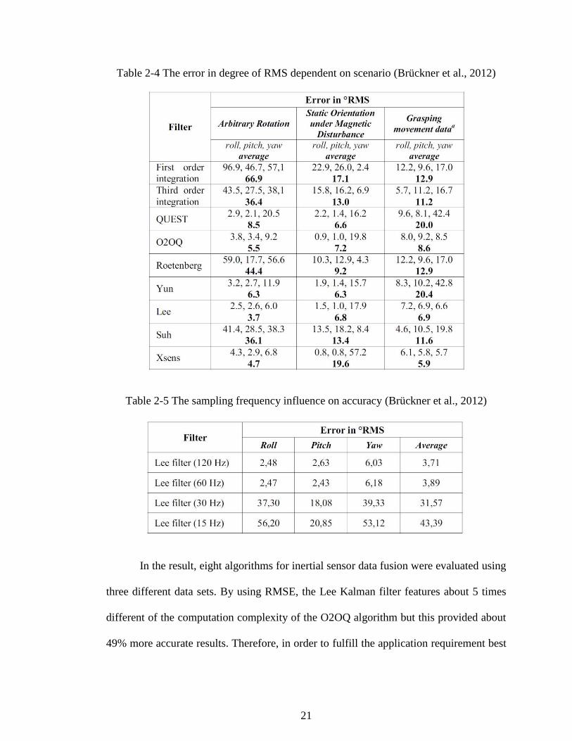
In the research of evaluation of inertial sensor fusion algorithms in grasping tasks
using real input data, the RMSE is used to evaluate the algorithms in three scenarios such
as the desired of an accuracy of 2o in human grasping movement signification application,
the estimation between Xsens sensor and Qualisys orientation. By using 24000 samples
of data-set, the accuracy of sampling frequency is determined from 120 Hz to 15 Hz. The
filter results before and after influenced with 120 Hz recorded Qualisys data are shown in
table 2.1, and 2.2, respectively (Brückner, Spindeldreier, & Blume, 2012).
21
Table 2-4 The error in degree of RMS dependent on scenario (Brückner et al., 2012)
Table 2-5 The sampling frequency influence on accuracy (Brückner et al., 2012)
In the result, eight algorithms for inertial sensor data fusion were evaluated using
three different data sets. By using RMSE, the Lee Kalman filter features about 5 times
different of the computation complexity of the O2OQ algorithm but this provided about
49% more accurate results. Therefore, in order to fulfill the application requirement best
22
with the computation complexity, the RMSE is very necessary to calculate the estimation
and the difference of the computation complexity.
2.6. Summary
This literature review chapter is a main basic part before starting the research. This
chapter provided the relevant researches which all the techniques can be explained with
the final result. There are three main sections in this chapter such as PID controller
optimization, velocity control of DC motor using optimization based PID controller,
maneuver control system, and the relative error calculation. Moreover, this chapter is
contributed a lot to this project.
23
CHAPTER 3
METHODOLOGY
3.1. Introduction
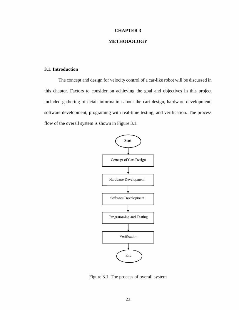
The concept and design for velocity control of a car-like robot will be discussed in
this chapter. Factors to consider on achieving the goal and objectives in this project
included gathering of detail information about the cart design, hardware development,
software development, programing with real-time testing, and verification. The process
flow of the overall system is shown in Figure 3.1.
Figure 3.1. The process of overall system

24
The car-like mobile robot designed is a main source where all important
information such as weight, width, length, height, and the distance between front wheels
and back wheels can be found in this section. Moreover, those information are necessary
for velocity control of a car-like mobile robot since car-like robot kinematic model is used
as a main maneuver control design.
Furthermore, hardware and software development are the two main sections in this
project. The hardware development covers development by adding some extra hardware
to the robot, and choosing a proper microcontroller to control the car-like mobile robot.
The software development included method or technique that can be used to the develop
the car-like robot.
Programing with testing describes how the designs are computed by using a
specific software, and verification of the design for velocity control of a car-like robot.
Once the programing has been implemented, the testing or doing some experiments over
the methods to the real-time robot need to be done to show the final output of using those
methods.
In order to confirm that those designs can be used for velocity control of a car-like
mobile robot, the verification section is necessary for every design. This verification
section error calculation between simulation generated and real-time testing result. When
error between simulation and real-time testing is high, the model can be define as failed
to use or acceptable to use with condition.